lokset resin cartridge anchors - tecnipro.it
TRANSCRIPT
Lokset® Resin Cartridge AnchorsFor Rock and Concrete Reinforcement
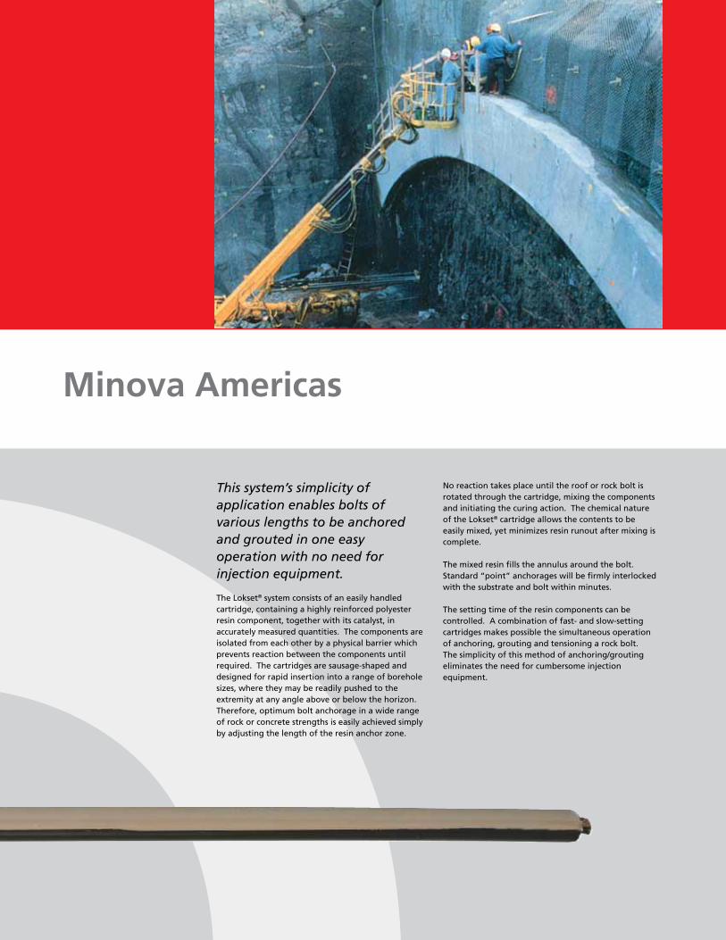
This system’s simplicity of application enables bolts of various lengths to be anchored and grouted in one easy operation with no need for injection equipment.
The Lokset® system consists of an easily handled cartridge, containing a highly reinforced polyester resin component, together with its catalyst, in accurately measured quantities. The components are isolated from each other by a physical barrier which prevents reaction between the components until required. The cartridges are sausage-shaped and designed for rapid insertion into a range of borehole sizes, where they may be readily pushed to the extremity at any angle above or below the horizon. Therefore, optimum bolt anchorage in a wide range of rock or concrete strengths is easily achieved simply by adjusting the length of the resin anchor zone.
Minova Americas
No reaction takes place until the roof or rock bolt is rotated through the cartridge, mixing the components and initiating the curing action. The chemical nature of the Lokset® cartridge allows the contents to be easily mixed, yet minimizes resin runout after mixing is complete.
The mixed resin fills the annulus around the bolt. Standard “point” anchorages will be firmly interlocked with the substrate and bolt within minutes.
The setting time of the resin components can be controlled. A combination of fast- and slow-setting cartridges makes possible the simultaneous operation of anchoring, grouting and tensioning a rock bolt. The simplicity of this method of anchoring/grouting eliminates the need for cumbersome injection equipment.
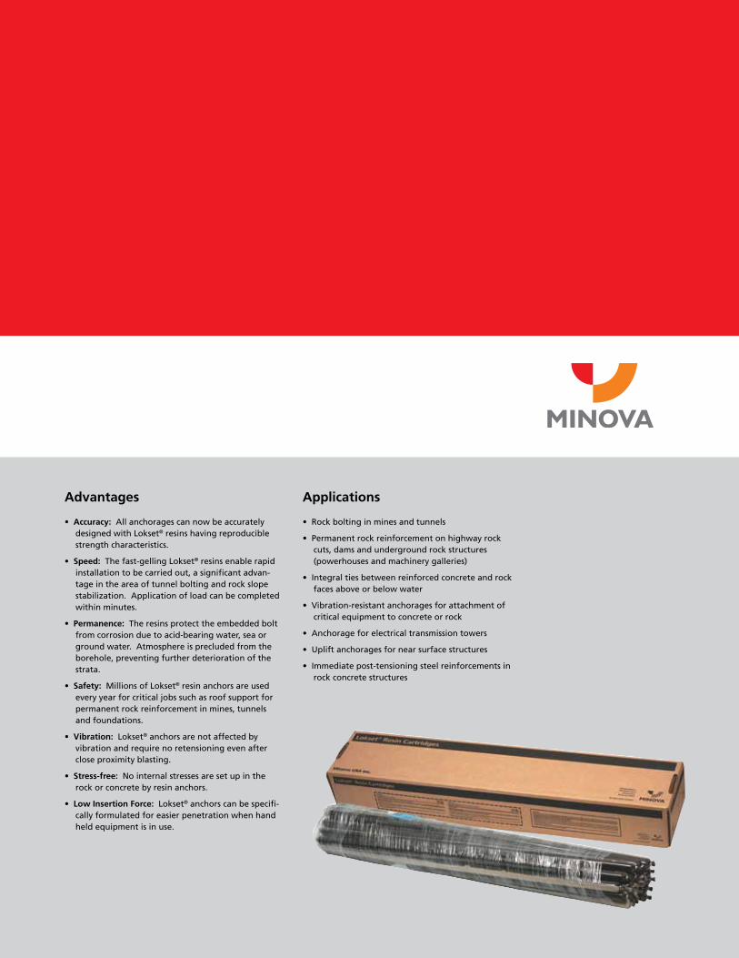
Advantages
• Accuracy: All anchorages can now be accurately designed with Lokset® resins having reproducible strength characteristics.
• Speed: The fast-gelling Lokset® resins enable rapid installation to be carried out, a significant advan-tage in the area of tunnel bolting and rock slope stabilization. Application of load can be completed within minutes.
• Permanence: The resins protect the embedded bolt from corrosion due to acid-bearing water, sea or ground water. Atmosphere is precluded from the borehole, preventing further deterioration of the strata.
• Safety: Millions of Lokset® resin anchors are used every year for critical jobs such as roof support for permanent rock reinforcement in mines, tunnels and foundations.
• Vibration: Lokset® anchors are not affected by vibration and require no retensioning even after close proximity blasting.
• Stress-free: No internal stresses are set up in the rock or concrete by resin anchors.
• Low Insertion Force: Lokset® anchors can be specifi-cally formulated for easier penetration when hand held equipment is in use.
Applications
• Rock bolting in mines and tunnels
• Permanent rock reinforcement on highway rock cuts, dams and underground rock structures (powerhouses and machinery galleries)
• Integral ties between reinforced concrete and rock faces above or below water
• Vibration-resistant anchorages for attachment of critical equipment to concrete or rock
• Anchorage for electrical transmission towers
• Uplift anchorages for near surface structures
• Immediate post-tensioning steel reinforcements in rock concrete structures
Installation Procedures
Installation of rock bolts with Lokset® cartridges can generally be carried out with equipment used to drill the boreholes. This includes track drills, tire mounted drills, jacklegs, stopers, and drill sash equipment constructed to handle long one-piece rock bolts or, when short “utility” type bolts are installed, with hand-held drilling equipment.
Boreholes
The system permits the placing of bolts in any position or angle above or below the horizon, in rock or concrete structures. Drill holes with rotary-percussive equipment to provide for the essential hole profile. Consult with Minova before attempting anchorages in diamond-drilled holes.
Holes must be flushed clear of cuttings and debris with air or water. Water remaining in, or entering into, the borehole during bolt placement has no effect on the integrity of anchor or grout zone involving anchorages in excess of 24 inches. However, water may cause hole deterioration in weak rock formations.
Holes may be telescoped. The work area in a tunnel or open rock excavation, for example, may be restricted, requiring the use of coupled rock bolts. To facilitate installation of long, coupled bolts, a larger diameter hole is drilled in the grout zone with a reduction in hole diameter carried out with the last section of drill steel. This ensures maximum
Installation Procedures
performance within the anchor zone and provides clearance in long boreholes for drill steel and rock bolt couplings.
Hole diameters for both anchor and grout zones should be within the range of borehole diameters permitted with a specific bolt diameter. Refer to the Lokset® Usage Chart.
Special Notes
In boreholes drilled purely by rotary means, or when underwater anchorages are considered, loadings will be reduced. Conduct anchorage tests to prove design assumptions.
Resin Cartridge Placement
Cartridges are dropped or pushed into position in the borehole. Vertical (down) holes or near horizontal holes offer no serious problem in placing resin cartridges. In vertical (up) holes, the use of basket clips and retainers (also known as parachute clips) will retain resin cartridges in the drill hole. The clips are attached to the base of the cartridge and are available in 23 mm (basket and parachute), 28 mm (basket and parachute) and 40 mm (basket) sizes. The use of “red caps,” inexpensive top hat-shaped plastic caps, will also retain resin cartridges in the drill hole. A wood dowel or plastic pipe can be used to transfer the resin cartridge(s) into position in the hole.
It is good construction practice to load no more than two cartridges at a time into the borehole.
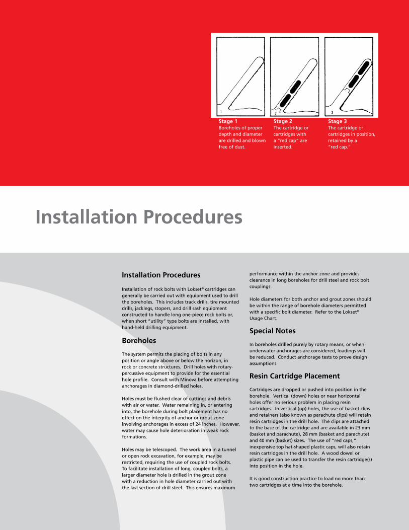
Stage 1Boreholes of proper depth and diameter are drilled and blown free of dust.
Stage 2The cartridge or cartridges with a “red cap” are inserted.
Stage 3The cartridge or cartridges in position, retained by a “red cap.”
Methods of Installing Lokset® Resin Cartridges
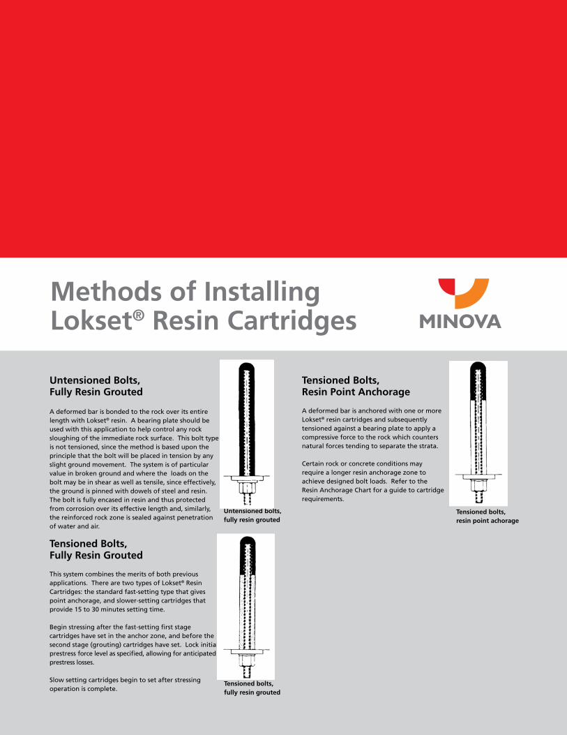
Untensioned Bolts, Fully Resin Grouted
A deformed bar is bonded to the rock over its entire length with Lokset® resin. A bearing plate should be used with this application to help control any rock sloughing of the immediate rock surface. This bolt type is not tensioned, since the method is based upon the principle that the bolt will be placed in tension by any slight ground movement. The system is of particular value in broken ground and where the loads on the bolt may be in shear as well as tensile, since effectively, the ground is pinned with dowels of steel and resin. The bolt is fully encased in resin and thus protected from corrosion over its effective length and, similarly, the reinforced rock zone is sealed against penetration of water and air.
Tensioned Bolts, Fully Resin Grouted
This system combines the merits of both previous applications. There are two types of Lokset® Resin Cartridges: the standard fast-setting type that gives point anchorage, and slower-setting cartridges that provide 15 to 30 minutes setting time.
Begin stressing after the fast-setting first stage cartridges have set in the anchor zone, and before the second stage (grouting) cartridges have set. Lock initial prestress force level as specified, allowing for anticipated prestress losses.
Slow setting cartridges begin to set after stressing operation is complete.
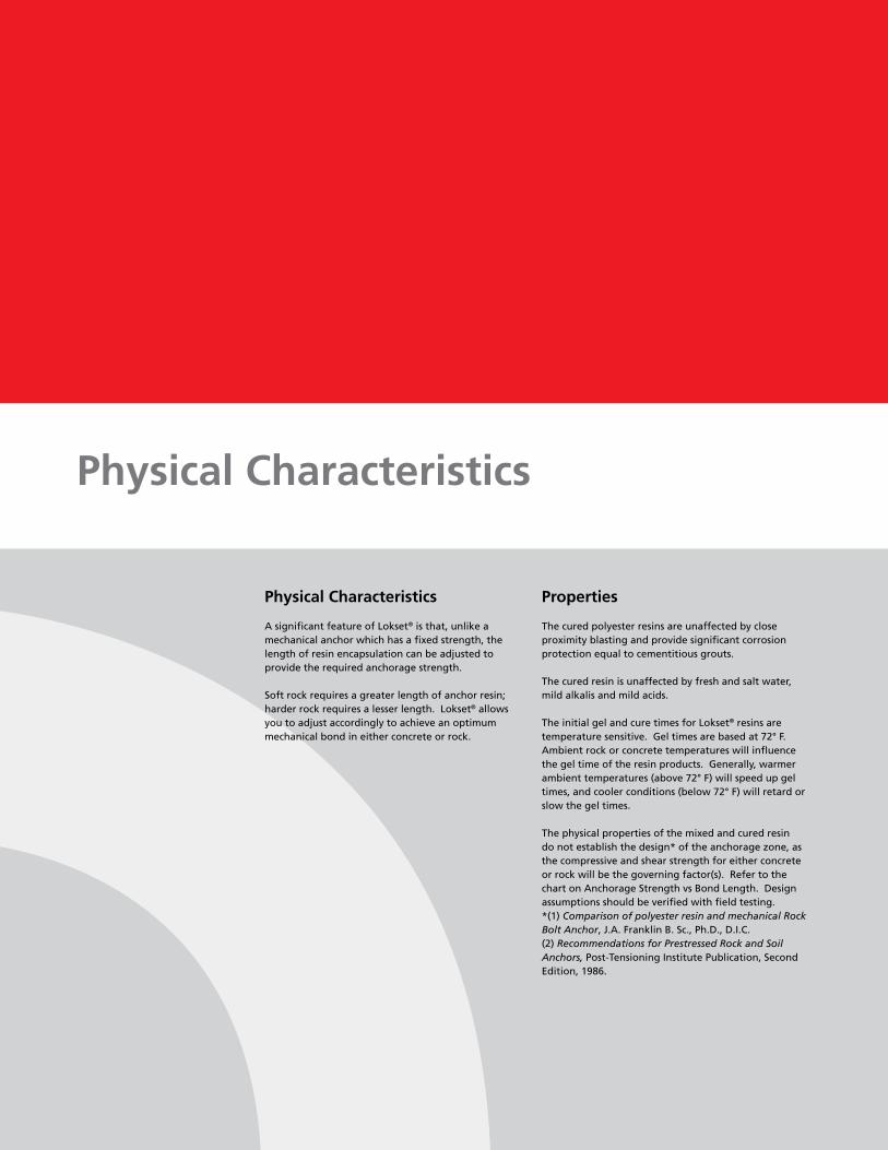
Tensioned Bolts, Resin Point Anchorage
A deformed bar is anchored with one or more Lokset® resin cartridges and subsequently tensioned against a bearing plate to apply a compressive force to the rock which counters natural forces tending to separate the strata.
Certain rock or concrete conditions may require a longer resin anchorage zone to achieve designed bolt loads. Refer to the Resin Anchorage Chart for a guide to cartridge requirements.
Tensioned bolts, resin point achorage
Untensioned bolts,fully resin grouted
Tensioned bolts, fully resin grouted
Physical Characteristics
A significant feature of Lokset® is that, unlike a mechanical anchor which has a fixed strength, the length of resin encapsulation can be adjusted to provide the required anchorage strength.
Soft rock requires a greater length of anchor resin; harder rock requires a lesser length. Lokset® allows you to adjust accordingly to achieve an optimum mechanical bond in either concrete or rock.
Physical Characteristics
Properties
The cured polyester resins are unaffected by close proximity blasting and provide significant corrosion protection equal to cementitious grouts.
The cured resin is unaffected by fresh and salt water, mild alkalis and mild acids.
The initial gel and cure times for Lokset® resins are temperature sensitive. Gel times are based at 72° F. Ambient rock or concrete temperatures will influence the gel time of the resin products. Generally, warmer ambient temperatures (above 72° F) will speed up gel times, and cooler conditions (below 72° F) will retard or slow the gel times.
The physical properties of the mixed and cured resin do not establish the design* of the anchorage zone, as the compressive and shear strength for either concrete or rock will be the governing factor(s). Refer to the chart on Anchorage Strength vs Bond Length. Design assumptions should be verified with field testing.*(1) Comparison of polyester resin and mechanical Rock Bolt Anchor, J.A. Franklin B. Sc., Ph.D., D.I.C.(2) Recommendations for Prestressed Rock and Soil Anchors, Post-Tensioning Institute Publication, Second Edition, 1986.
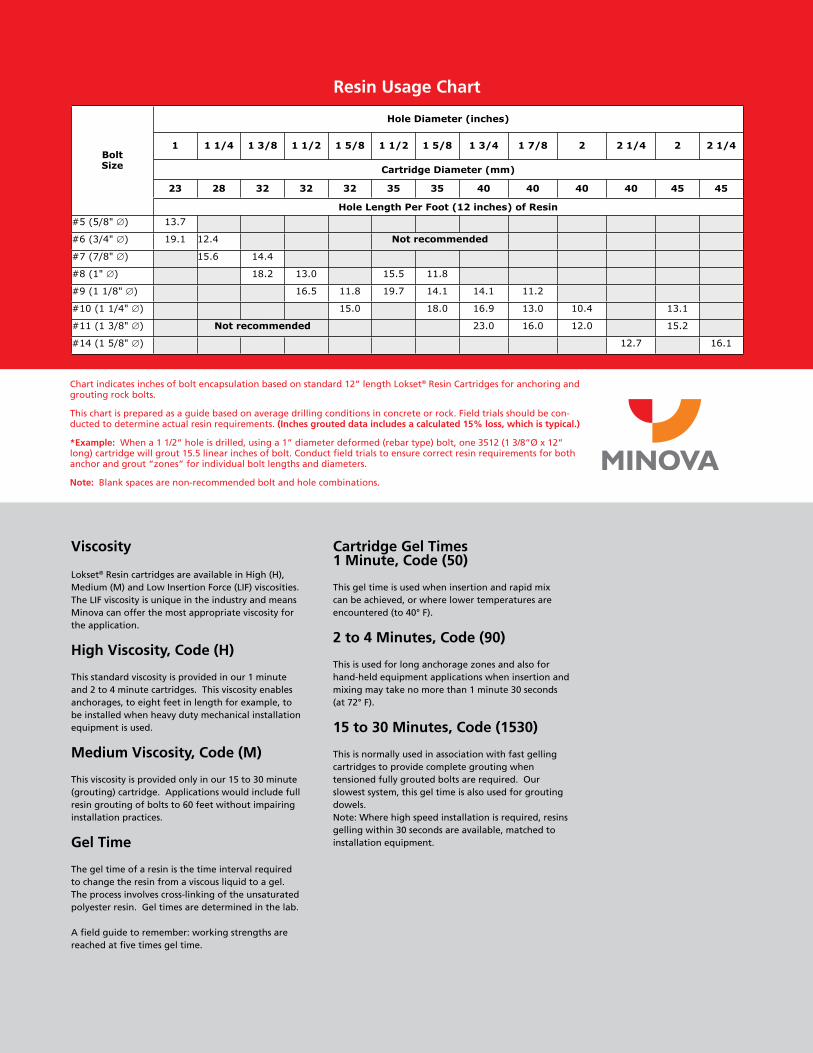
Resin Usage Chart
Viscosity
Lokset® Resin cartridges are available in High (H), Medium (M) and Low Insertion Force (LIF) viscosities. The LIF viscosity is unique in the industry and means Minova can offer the most appropriate viscosity for the application.
High Viscosity, Code (H)
This standard viscosity is provided in our 1 minute and 2 to 4 minute cartridges. This viscosity enables anchorages, to eight feet in length for example, to be installed when heavy duty mechanical installation equipment is used.
Medium Viscosity, Code (M)
This viscosity is provided only in our 15 to 30 minute (grouting) cartridge. Applications would include full resin grouting of bolts to 60 feet without impairing installation practices.
Gel Time
The gel time of a resin is the time interval required to change the resin from a viscous liquid to a gel. The process involves cross-linking of the unsaturated polyester resin. Gel times are determined in the lab.
A field guide to remember: working strengths are reached at five times gel time.
Chart indicates inches of bolt encapsulation based on standard 12” length Lokset® Resin Cartridges for anchoring and grouting rock bolts.
This chart is prepared as a guide based on average drilling conditions in concrete or rock. Field trials should be con-ducted to determine actual resin requirements. (Inches grouted data includes a calculated 15% loss, which is typical.)
*Example: When a 1 1/2” hole is drilled, using a 1” diameter deformed (rebar type) bolt, one 3512 (1 3/8”Ø x 12” long) cartridge will grout 15.5 linear inches of bolt. Conduct field trials to ensure correct resin requirements for both anchor and grout “zones” for individual bolt lengths and diameters.
Note: Blank spaces are non-recommended bolt and hole combinations.
Cartridge Gel Times1 Minute, Code (50)
This gel time is used when insertion and rapid mix can be achieved, or where lower temperatures are encountered (to 40° F).
2 to 4 Minutes, Code (90)
This is used for long anchorage zones and also for hand-held equipment applications when insertion and mixing may take no more than 1 minute 30 seconds (at 72° F).
15 to 30 Minutes, Code (1530)
This is normally used in association with fast gelling cartridges to provide complete grouting when tensioned fully grouted bolts are required. Our slowest system, this gel time is also used for grouting dowels.Note: Where high speed installation is required, resins gelling within 30 seconds are available, matched to installation equipment.
BoltSize
Hole Diameter (inches)
1 1 1/4 1 3/8 1 1/2 1 5/8 1 1/2 1 5/8 1 3/4 1 7/8 2 2 1/4 2 2 1/4
Cartridge Diameter (mm)
23 28 32 32 32 35 35 40 40 40 40 45 45
Hole Length Per Foot (12 inches) of Resin
#5 (5/8" ∅) 13.7
#6 (3/4" ∅) 19.1 12.4 Not recommended
#7 (7/8" ∅) 15.6 14.4
#8 (1" ∅) 18.2 13.0 15.5 11.8
#9 (1 1/8" ∅) 16.5 11.8 19.7 14.1 14.1 11.2
#10 (1 1/4" ∅) 15.0 18.0 16.9 13.0 10.4 13.1
#11 (1 3/8" ∅) Not recommended 23.0 16.0 12.0 15.2
#14 (1 5/8" ∅) 12.7 16.1
Introduction
Installation of Lokset® Resin polyester resin cartridges in rock and concrete have ranged from application of short 3/4” rebar “starter bars” into concrete to 1-3/8” diameter bolts for rock reinforcement, measuring 55’ in length, weighing over 300 lbs and fully embedded in resin!
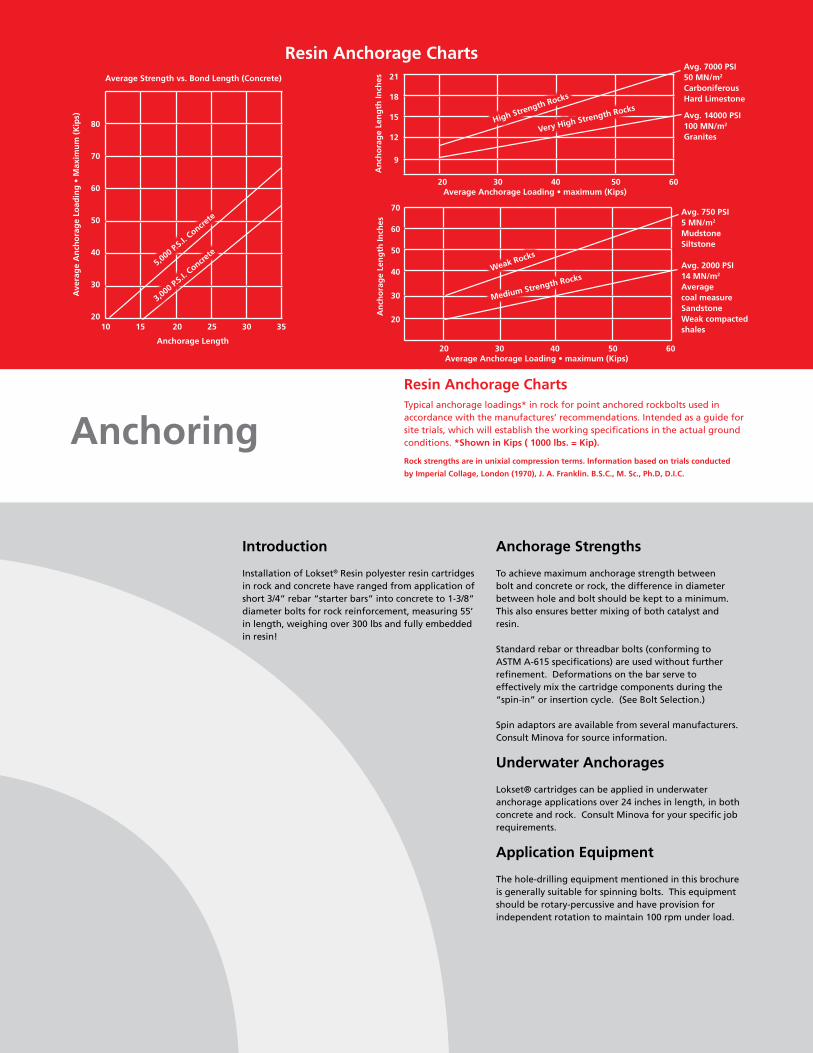
Resin Anchorage ChartsTypical anchorage loadings* in rock for point anchored rockbolts used in accordance with the manufactures’ recommendations. Intended as a guide for site trials, which will establish the working specifications in the actual ground conditions. *Shown in Kips ( 1000 lbs. = Kip).
Rock strengths are in unixial compression terms. Information based on trials conducted
by Imperial Collage, London (1970), J. A. Franklin. B.S.C., M. Sc., Ph.D, D.I.C.
Anchoring
Anchorage Strengths
To achieve maximum anchorage strength between bolt and concrete or rock, the difference in diameter between hole and bolt should be kept to a minimum. This also ensures better mixing of both catalyst and resin.
Standard rebar or threadbar bolts (conforming to ASTM A-615 specifications) are used without further refinement. Deformations on the bar serve to effectively mix the cartridge components during the “spin-in” or insertion cycle. (See Bolt Selection.) Spin adaptors are available from several manufacturers. Consult Minova for source information.
Underwater Anchorages
Lokset® cartridges can be applied in underwater anchorage applications over 24 inches in length, in both concrete and rock. Consult Minova for your specific job requirements.
Application Equipment
The hole-drilling equipment mentioned in this brochure is generally suitable for spinning bolts. This equipment should be rotary-percussive and have provision for independent rotation to maintain 100 rpm under load.
10 15 20 25 30 35
80
70
60
50
40
30
20
Average Strength vs. Bond Length (Concrete)
Anchorage Length
Ave
rag
e A
nch
ora
ge
Load
ing
• M
axim
um
(K
ips)
5,000 P.S.I.
Concrete
3,000 P.S.I.
Concrete
High Strength Rocks
Very High Strength Rocks
20 30 40 50 60
21
18
15
12
9
An
cho
rag
e Le
ng
th In
ches
Average Anchorage Loading • maximum (Kips)
Avg. 7000 PSI50 MN/m2
CarboniferousHard Limestone
Avg. 14000 PSI100 MN/m2
Granites
Weak Rocks
Medium Strength Rocks
20 30 40 50 60
70
60
50
40
30
20
An
cho
rag
e Le
ng
th In
ches
Average Anchorage Loading • maximum (Kips)
Avg. 750 PSI5 MN/m2
MudstoneSiltstone
Avg. 2000 PSI14 MN/m2
Averagecoal measureSandstoneWeak compacted shales
Resin Anchorage Charts

In order to achieve maximum performance of the Lokset® cartridge, the cartridge must be installed in a borehole of specific dimensions and characteristics, and it must be mixed with a steel bolt, also of defined dimension and shape. (Refer to Resin Usage Chart.)
Cartridge Selection
Available in three standard gel times, the cartridge is manufactured in six diameters. Standard cartridge length is 12 inches. Lokset® Resin Cartridges are also available in longer lengths to facilitate rapid installation of material. Contact Minova for information and pricing.
The Lokset® cartridge consists of a filled polyester mastic and a catalyst paste, contained in a heat-sealed tube of polyester film. A film barrier prevents premature chemical reaction until the anchor bolt ruptures and mixes the contents.
For proper cartridge selection, see Resin Usage Chart.
Bolt Selection
Standard rebar, threadbar or deformed fiberglass rod can be used without further refinement.
Deformations on the bar are essential to mix the resin components during the spin-in cycle. Bolt stressing, where specified, is generally carried out with center-hole hydraulic jack to insure accuracy of the applied load.
Note: Contact your local Minova representative for suggestions when using coil rods and all-thread rods to ensure complete mixing of resin components.
Gel Time Vs Temperature
The resin gel time and cure time are temperature sensitive. To ensure proper behavior, the ambient temperature of the rock or concrete must be monitored.
Gel Time Selection
Temperature conditions and application affect the specific cartridges required. Refer to the charts above and below.
Resin Strength Vs Cure Time
Cartridge, Bolt, Gel Time Selection
Cure Time (Minutes) at 72°F
100
80
60
40
20
% o
f Fi
nal
Str
eng
th
H90 Lokset® Resin
H50 Lokset® Resin
M1530 Lokset® Resin
10 20 30 40 50 60 70
Temperature °F
35
30
25
20
15
10
5
Gel
Tim
e M
inu
tes
H90 Lokset® Resin
H50 Lokset® Resin
100° 90° 80° 70° 60° 50° 40°
M1530 Lokset® Resin

Storage Procedures
Lokset® cartridges should be stored in a cool, well-ventilated and dry area away from direct sunlight. High temperature conditions can reduce shelf life. Cartridges stored in extreme temperatures should be “normalized” at 50° F to 70° F for at least two days prior to use to provide the expected gel time.
Pallets should not be stacked. Stock rotation is recommended so that the oldest stock is used first.
Safe Handling Procedures
Refer to the material safety data sheet. Do not open or puncture cartridges prior to insertion. Contents of cartridges may cause mild irritation, and contact should be avoided. Use in adequately ventilated areas. Avoid prolonged inhalation of vapor. Eye protection should always be used when bolting. If resin contacts the eyes, flush immediately with water for at least 15 minutes. Seek medical attention.
Typical Lokset® Resin Anchor Applications
Order Code (1)
Cartridge Diameter (inches) (mm) Pieces Per Carton Net Weight
Per Carton
2312 15/16 23 50 27.6 lbs.
2812 1-1/8 28 30 24.1 lbs.
3212 1-1/4 32 25 26.9 lbs.
3512 1-3/8 35 20 25.0 lbs.
4012 1-9/16 40 16 26.3 lbs.
4512 1-3/4 45 12 25.1 lbs.
Stilling Basin Rock Anchors.Smithland Dam, Ohio River.Army Corps of Engineers, Nashville District.
Roof bolts in diversion tunnel.Paintsville Lake Dam, Kentucky.Army Corps of Engineers, Huntington District.
Packaging
Minimum shipment; single full cartons. A full pallet contains 75 cartons of standard 12-inch cartridges.Do not forget to specify gel time.
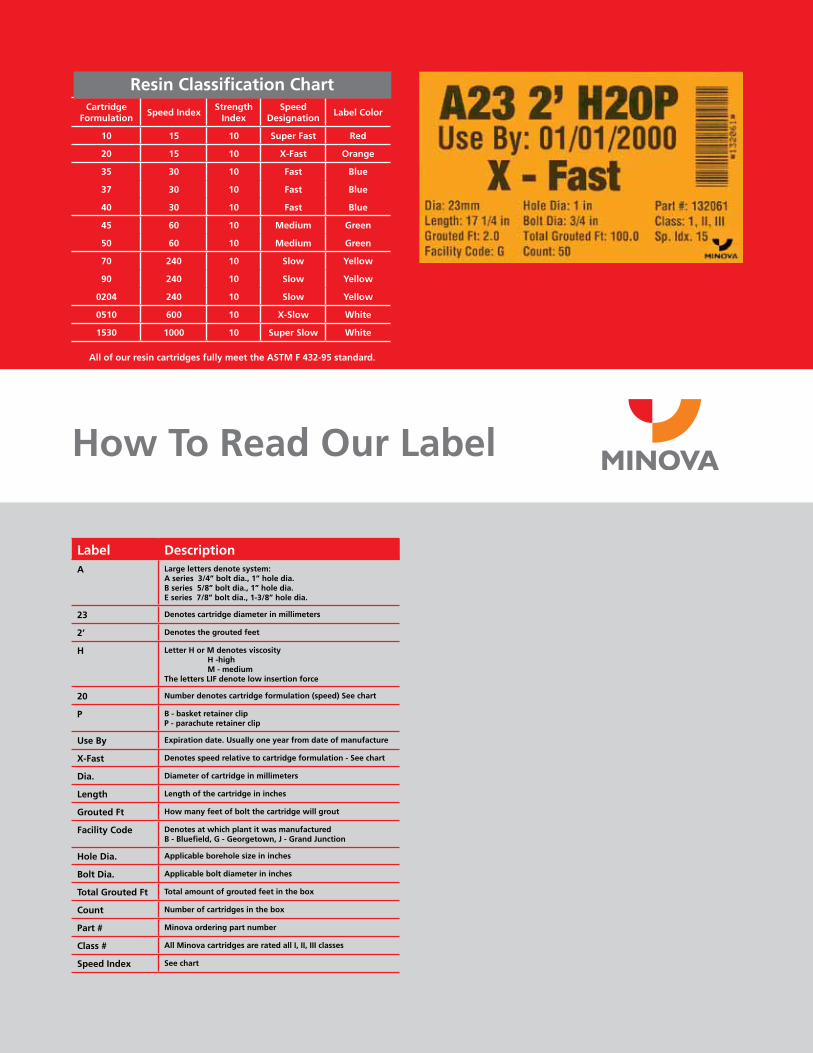
How To Read Our Label
All of our resin cartridges fully meet the ASTM F 432-95 standard.
Cartridge Formulation
Speed IndexStrength
IndexSpeed
DesignationLabel Color
10 15 10 Super Fast Red
20 15 10 X-Fast Orange
35 30 10 Fast Blue
37 30 10 Fast Blue
40 30 10 Fast Blue
45 60 10 Medium Green
50 60 10 Medium Green
70 240 10 Slow Yellow
90 240 10 Slow Yellow
0204 240 10 Slow Yellow
0510 600 10 X-Slow White
1530 1000 10 Super Slow White
Resin Classification Chart
Label DescriptionA Large letters denote system:
A series 3/4” bolt dia., 1” hole dia.B series 5/8” bolt dia., 1” hole dia.E series 7/8” bolt dia., 1-3/8” hole dia.
23 Denotes cartridge diameter in millimeters
2’ Denotes the grouted feet
H Letter H or M denotes viscosity H -high M - mediumThe letters LIF denote low insertion force
20 Number denotes cartridge formulation (speed) See chart
P B - basket retainer clipP - parachute retainer clip
Use By Expiration date. Usually one year from date of manufacture
X-Fast Denotes speed relative to cartridge formulation - See chart
Dia. Diameter of cartridge in millimeters
Length Length of the cartridge in inches
Grouted Ft How many feet of bolt the cartridge will grout
Facility Code Denotes at which plant it was manufactured B - Bluefield, G - Georgetown, J - Grand Junction
Hole Dia. Applicable borehole size in inches
Bolt Dia. Applicable bolt diameter in inches
Total Grouted Ft Total amount of grouted feet in the box
Count Number of cartridges in the box
Part # Minova ordering part number
Class # All Minova cartridges are rated all I, II, III classes
Speed Index See chart
Minova Americas
150 Carley Court
Georgetown, KY 40324
USA
Phone 800 520 6621
Fax 502 863 1374
Email [email protected]
Website www.minovaamericas.com
Important Note: WarrantyMinova USA Inc. warrants that its products, at the time of shipment, conform to the applicable descriptions set forth in the invoice and are free from defects in material and workmanship. NO OTHER WARRANTY, WHETHER EXPRESS, IMPLIED OR STATUTORY, INCLUDING ANY WARRANTY OF MERCHANT-ABILITY, OR FITNESS FOR A PARTICULAR PURPOSE, SHALL EXIST IN CONNECTION WITH THE SALE OR USE OF ANY MINOVA USA INC. PRODUCT, AND ALL SUCH WARRANTIES ARE HEREBY EXPRESSLY DISCLAIMED AND EXCLUDED.
All claims under this warranty must be made in writing to Minova USA Inc. within 15 days after discovery of the defect, and within 90 days of the date of shipment by Minova USA Inc. of the product claimed defective. Upon timely receipt of a claim, Minova USA Inc. shall have the option either to inspect the product while in Buyer’s possession or to request Buyer to return the product to Minova USA Inc. for inspection. Claims not made as provided above and within the applicable time period will be barred. All warranties shall be null and void if the products have not been stored and used in accordance with procedures recommended by Minova USA Inc.
Minova USA Inc. shall, at its option, either replace the nonconforming or defective product or refund to Buyer its purchase price. The foregoing consti-tutes Buyer’s sole and exclusive remedy for any breach or warranty.
November 2009
A member of the Orica Group