long baseline neutrino experiment (lbne) target … baseline neutrino experiment (lbne) target...
TRANSCRIPT

Long Baseline Neutrino Experiment (LBNE) Target Material Radiation Damage from Energetic Protons of the Brookhaven Linear Isotope Production (BLIP) Facility
Prepared by N. Simos Contributions from: H. Ludewig, H. Kirk, J. O Conor, Z. Kotsina* Brookhaven National Laboratory Upton, NY 11973 *Demokritos National Center for Scientific Research, Athens, Greece P. Hurh and N. Mokhov Contributions from: J. Misek, R. Zwaska, J. Hylen Fermi National Accelerator Laboratory Batavia, IL 60510
Final Draft Version – November 2012

i
TABLE OF CONTENTS
Abstract ………………………………………………………………………………………………………………… ii Executive Summary ……………………………………………………………………………………………………. iii Acknowledgements ……………………………………………………………………………………………………. vi
1.0 Introduction ……………………………………………………………………………………………………. 1 1.1 Target Material and Requirements ……………………………………………………………….. 1 1.2 Radiation Damage in Graphite ……………………………………………………………….. 2 1.3 Radiation Damage in C/C Composite ……………………………………………………. 7 1.4 Experimental Objectives ……………………………………………………………………………. 16
2.0 Irradiation of Target Materials ……………………………………………………………………………. 18
2.1 Pre-Irradiation Characterization of Graphite and 3D C/C Composite …… 18 2.2 BLIP Irradiation Target Set-Up and Environment ………………………………………… 20
3.0 Post-Irradiation Examination Description ………………………………………………………………… 29
4.0 Results …………………………………………………………………………………………………………………. 33
4.1 LBNE Graphites – Post-Irradiation Assessment ………………………………………… 33 4.1.1 Thermal conductivity assessment ………………………………………… 33 4.1.2 Thermal stability and damage annealing …………………………….. 34 4.1.3 Damage reversal during annealing …………………………………………. 41 4.1.4 Mechanical testing of irradiated LBNE graphite …………………. 43 4.1.5 Radiation-induced stiffness changes in graphite – ultrasound
method ……………………………………………………………………………... 49 4.2 C/C Composite Post-Irradiation Assessment …………………………………………. 55
4.2.1 Thermal annealing and dimensional changes …………………………….. 57 4.2.2 Weight loss measurements …………………………………………………….. 60 4.2.3 Mechanical testing of 3D C/C Composite …………………………….. 61 4.2.4 Ultrasonic testing of 3D C/C Composite …………………………….. 63 4.2.5 Thermal conductivity …………………………………………………………………. 63
4.3 h-BN Post-Irradiation Assessment …………………………………………………………………. 63
5.0 Discussion of Results and Conclusions …………………………………………………………………. 68
6.0 Future Work ………………………………………………………………………………………………..……. 71
Appendices ……………………………………………………………………………………………………………..….. 72 Appendix A ……………………………………………………………………………………………………… 73 Appendix B ……………………………………………………………………………………………………… 82 Appendix C ……………………………………………………………………………………………………… 91 References ………………………………………………………………………………………………………………….. 101

ii
ABSTRACT Multi-MW high performance particle production targets are key toward the next generation of accelerator machines for future neutrino and other rare particle beams. One of the future multi-MW accelerators is the LBNE Experiment where Fermilab aims to produce a beam of neutrinos with a 2.3 MW proton beam (1.6e14 p/pulse, σ radius of 1.5-3.5 mm, and 9.8 µs pulse length) as part of a suite of experiments associated with Project X. These parameters are expected to push many target materials to their limit thus making the target design very challenging. To address these critical issues, a series of experimental studies on radiation damage were conducted a Brookhaven National Lab, with focus on low-Z materials (four graphite grades (POCO, IG430, SGL R7650, C-2020), 3D C/C and h-BN). The properties of the different target materials, irradiated at varying DPA levels, were measured. This report presents results to show how the properties of the materials vary as a result of radiation damage as well as the damage reversal effects due to post-irradiation annealing. Mechanical properties, such as the tensile strength and elastic modulus, for each of the material grades were seen to increase with radiation damage and reduce with post-irradiation annealing to temperatures above the irradiation temperature. On the other hand, the coefficient of thermal expansion (CTE) for the target materials was shown to decrease during the first cycle of thermal annealing but increase significantly during the second thermal annealing cycle. Detailed explanation of interstitial atom and vacancy mobility is given in the report to support the observed damage reversal annealing process of the graphite grades.

iii
EXECUTIVE SUMMARY Experiments using the next generation multi-MW power accelerators will require high-performance and high reliability particle production targets to generate intense neutrino and other rare particle beams. The understanding of the behavior of target materials responsible for producing the secondary particles reliably is critical, given that future experiments will represent an order of magnitude increase in power demand. The primary concerns for the target materials are (a) the accumulated radiation damage and the consequences manifested in the resulting change of their physio-mechanical properties that control target design and operation, and (b) their ability to withstand thermal shock while key properties are changing as a result of accumulated radiation effects. To satisfy the physics requirements of these multi-MW level experiments, target materials are selected on the basis of the desired secondary particle spectra. While for a number of the optimal material choices there exist a body of knowledge especially from the operation of fission nuclear reactors where high thermal integrated neutron fluxes interact with the materials and alter their physical and mechanical properties, these accelerators involve highly energetic protons. The effects of highly energetic protons may be significantly different on these target materials at high fluence levels due to increased generation of transmutation products, high displacement dose rate, kinetics of irradiation-induced defect production/accumulation behavior and the irradiation temperature. Therefore, qualification, quantification and structural damage limit identification studies on choice target materials for these experiments are required under conditions that closely resemble the operating environment. Dedicated radiation damage studies conducted within the last decade at BNL using 200 MeV protons at the Brookhaven Linear Isotope Producer (BLIP) target station for LHC and Neutrino Factory revealed a surprising proton structural damage fluence limit of about 1021 p/cm2 for graphite and carbon composites. The effective energy range of the protons interacting with these materials which are considered as potential candidates for LBNE was between 120-200 MeV. Target performance results for the NuMI experiment where a graphite target intercepted 120 GeV protons indicated that the target material may also adhere to similar fluence limitations (factor of 4 higher in fluence for NuMI due to higher proton energy). Proton-matter interaction studies following the observations of these limiting fluence thresholds and spanning a wide range of energies confirmed and explained the higher rate of damage observed in the BNL BLIP radiation damage experiments. Prompted by these experimental and operational observations on targets made of materials desired for the multi-MW LBNE, a comprehensive experimental effort was launched to assess and quantify potential limitations of LBNE target materials using the accelerated damage properties of the BNL 120-200 MeV proton beams. The objectives were to (a) confirm the structural damage fluence of the carbon composite when irradiated in a water environment and compare it with the performance of the same target material in an inert gas atmosphere where the potential effects of the water environment are eliminated, (b) evaluate the irradiation-induced changes in the lattice of a various grades of graphite and address damage as a function of proton fluence to provide estimates of LBNE target life expectancy, (c) qualify and quantify the performance of

iv
materials/alloys other than graphite and carbon that are within the optimal Z regime for generating the desired low energy neutrino spectrum and (d) explore potential in-situ damage reversal processes that will help extend the LBNE target lifetime. The material matrix included in the BNL BLIP test include 3D C/C composite in water and argon environments, POCO ZXF-5Q graphite, Toyo-Tanso IG-430 graphite, Carbone-Lorraine 2020 graphite, SGL R7650 graphite and hexagonal Boron Nitride h-BN all in argon atmospheres. The optimal irradiation duration, given by the BNL Linac beam parameters and the isotope production flux and energy requirements, was identified as a 9-week irradiation period, which produced damage in the target materials equivalent to 1/5 of LBNE year at 700 kW power. The material matrix received an integrated beam current of about 120, 000 µA-hours and following several months of cool-down time, the specimens were tested to study the material property changes associated with radiation damage and damage reversal annealing. Post-irradiation testing involved the measurement of the coefficient of thermal expansion, thermal conductivity, tensile strength and elastic modulus.
Radiation damage, at varying DPA levels, caused significant changes in the properties of the different materials relative to unirradiated specimens. The coefficient of thermal expansion (CTE) of the irradiated specimens showed a significant decrease during the first thermal cycle measurement. However, during the second thermal cycle, the CTE value was higher than that of the unirradiated CTE value. The initial decrease in CTE during the first cycle is due to the annealing of the interstitial atoms at temperatures higher than the irradiation temperature. Once annealing has taken place during the first cycle, the graphite then shows an increase in CTE during the second cycle, indicating that the interstitial atoms mobile up to the annealing temperature have already been placed back in the lattice, or pinned at grain boundaries. Using a multi-stage annealing process, both the above trend and the establishment of the irradiation temperature was confirmed. The SGL R7650 and POCO graphites showed the most dimensional changes as a function of temperature while the IG-430 graphite was the most stable. Both the tensile strength and elastic modulus of the graphite grades showed an increase due to radiation damage. However, following annealing at temperature above the irradiation temperature, the tensile properties were partially recovered. POCO displayed a greater percentage recovery than IG430. The latter is likely due to the fine-grained structure of IG430 that provides sinks for interstitial and places for transmutation products such as He and H to collect – this in turns restrict full recovery through annealing. The 3D C/C specimens that were in direct contact with water showed greater damage than the corresponding specimens placed in the argon-purged environment. This confirmed that the environment in which the target is in plays a role in its structural degradation. Finally, h-BN was ruled out as a potential candidate for the LBNE target due to its very weak mechanical properties prior to irradiation. The report incorporates an extensive array of results associated with the effects of proton irradiation. Most importantly, and based on the post-irradiation observations, it provides (a) a comprehensive assessment of the resilience of the different irradiated materials in maintaining their physical and mechanical integrity, (b) assessment of the irradiation environment and its influence on the material during beam interaction, and (c) recommendations to LBNE on the

v
materials from the tested matrix that should remain as candidates and be studied further for life expectancy identification. The report consists of several chapters and Appendices. In Chapter 1 the overall issue of irradiation damage in LBNE target materials is presented along with recent experimental and operational results that prompted the BNL BLIP irradiation study. The main objectives of the present study are also listed. Chapter 2 describes each of the target material chosen as well as the BLIP irradiation target-set up and characterization. The instruments and facilities used to carry out the post-irradiation analyses are described in Chapter 3. Chapter 4 presents the results and analyses from the tests for each of the target material. A discussion of the results and specific recommendations on the tests are given in Chapter 5. Finally, Chapter 6 lists a number of follow-up studies that will help close the knowledge gaps and strengthen the initial findings from this work.

vi
ACKNOWLEDGEMENTS LBNE Project Management: J. Strait, V. Papadimitriou, Robert Zwaska. BNL Support: L. Mausner, H. Ludewig, H. Kirk, J. O Conor, Z. Kotsina. Fermilab Support: J. Misek, J. Hylen, K. Ammigan, J. Wilson.

1
1.0 INTRODUCTION
Current high energy physics experiments (NuMI-MINOS, T2K) utilize primary beams (usually highly energetic protons) with power levels in the hundreds of kW on targets to generate neutrino and other rare particle beams. Next generation accelerators will drive high energy physics experiments requiring high-performance and high reliability particle production targets at the multi-MW level. This increase represents an order of magnitude jump in beam power and requires an associated expansion of our understanding of the behavior of materials in response to such intense proton beams. Of primary concerns are the accumulated radiation damage in these materials and the associated changes in the physical and mechanical properties that limit target survival. To satisfy the physics requirements of these multi-MW level experiments, target materials are selected on the basis of the desired secondary particle spectra and the downstream beamline optics. While for a number of the optimal target material choices there exists a body of knowledge concerning radiation damage (stemming primarily from fission power R&D), there is relatively little knowledge of response of these materials to highly energetic protons. Radiation damage resulting from high energy particles is expected to be significantly different from low energy particles, primarily due to enhanced generation of transmutation products (particularly gas production). Therefore, radiation damage studies of candidate target materials for these experiments are required under conditions that closely resemble the eventual operating environment. 1.1 Target Material Requirements The Long Baseline Neutrino Experiment (LBNE) at Fermilab is one these future experiments that enter the multi-MW power level, aiming to produce a beam of low energy neutrinos with a 2.3 MW, 120 GeV pulsed proton beam. The LBNE plan calls for low-Z targets subjected to a pulsed proton beam of the order of 1.6e14 protons/pulse, σ radius of 1.5-3.5 mm and a 9.8 µs pulse length. These parameters are expected to push many target materials to their limit and beyond, thus making the design and operation of a target system very challenging. Recent experiences from operating high intensity beams on targets (anti-proton source and NuMI-MINOS) have indicated that heat removal and thermal shock are two critical design issues, besides radiation damage. In order to keep operating temperatures at a reasonable level, conducting the heat generated in the beam interaction region of the target out to a cooling system is critical. Thus, decreasing the thermal resistance of the cooling path is generally desired. This is highly dependent upon the thermal conductivity of the target material since many of the geometrical aspects of the targets are constrained by the physics optimization. If radiation damage to the target material degrades the thermal conductivity, then overheating and target degradation may limit the target lifetime. In a similar but more complex fashion, resistance to thermal shock is affected by radiation damage. Thermal shock refers to the effect of sudden heating of a portion of material surrounded by cooler material that is not heated. In the case of pulsed beam on target, such as planned for LBNE, the primary beam heats a small volume of the target material by several hundred degrees Celsius in about 10 microseconds. Since the heated volume is surrounded by cooler material, the heated volume cannot expand and develops a large associated compressive stress. The sudden appearance

2
of this stress region creates a compressive stress wave moving radially outward from the interaction region. When the stress wave encounters free boundaries, it reflects as a tensile stress wave. If the initial compressive stress wave does not fail the material, then the constructive interference of tensile waves at surface discontinuities may still fail the material. Note that this stress wave is not a shock wave since typically the rate of loading is too slow compared to the speed of sound in the target material. A material’s resistance to thermal shock is dependent upon several material properties. A high tensile strength allows the material to survive peak stresses resulting from the initial stress wave. A low modulus of elasticity reduces the magnitude of the initial stress wave for a given amount of thermal strain. A low coefficient of thermal expansion reduces the magnitude of the induced thermal strain for a given temperature rise. And a high heat capacity reduces the magnitude of the temperature rise for a given energy deposition (and thus also the associated stress wave). All of these four properties are affected by radiation damage. As a result, a given material’s response to high energy proton radiation damage is critical to predicting target lifetime. The material properties of industrial graphite, used in the NuMI-MINOS target, overcome these critical design issues, at least in the unirradiated state. In addition, experience with the graphite used in the NuMI-MINOS target has been relatively successful (aside from possible radiation damage discussed in Section 1.2). Therefore the “default” target material for LBNE has been chosen to be graphite. However, as radiation damage occurs, the material properties for graphite undergo significant change at relatively low dose (Section 1.2). In addition, operational experience has indicated that significant degradation in graphite structural integrity resulting in decreased secondary particle yield, will limit the lifetime of a graphite target under these conditions. Therefore, a better understanding of radiation damage in graphite is required to qualify candidate graphite materials for use in the LBNE target. In addition, suitable alternative materials should be researched for possible use in LBNE.
1.2 Radiation Damage in Graphite
Radiation damage in solids by high-energy proton beam is primarily caused by nuclear (inelastic and elastic) and EM (photon) elastic interactions with the atomic structure of the target material. These interactions displace atoms from their equilibrium positions in a crystalline lattice forming interstitial and vacancy defects. As a result, these defects agglomerate and move within the lattice to form dislocation loops and other microstructural formations, which can significantly affect physical and structural material properties. Highly ordered materials, such as pyrolytic graphite, which derive their unique (usually anisotropic) properties due to that consistent structure, are much more likely to see large changes in properties at relatively low doses of radiation. More isotropic, fine-grained materials, which have randomly oriented crystal grains, such as amorphous graphite, tend to see less relative change in properties for the same level of radiation (although they lack the unique properties of the highly ordered materials to begin with). In addition to atomic displacements, transmutation due to inelastic collisions can create significant production of gas atoms (hydrogen and helium isotopes) within the target material. Entrapped gas atoms can contribute to swelling and, when accumulated at void locations, can cause gas bubbles and blistering. Some materials are susceptible to hydrogen and/or helium embrittlement at grain boundaries. Due to the high energy of the incident particles, proton irradiation from particle

3
accelerators creates orders of magnitude more gas production than the low energy neutron spectrum of a fission reactor environment. Thus, extending the body of knowledge existing from reactor based radiation damage experiments to the high-energy proton regime is difficult at best. The structure of graphite is depicted in Figure 1.1 and consists of a series of layers parallel to the basal plane of hexagonally linked carbon atoms. In this stable hexagonal lattice, the inter-atomic distance within a layer plane, a, is 1.415 Å and the interlayer distance, d, between planes is 3.354 Å. Strong chemical bonding forces exist within the layer planes, yet the bonding energy between planes is only about 2% of that within the planes (150-170 kcal/gram-atom vs. 1.3-4 kcal/gram-atom). These weaker bonds between the planes are attributed to either van der Waals forces or orbitals overlap on adjacent atoms in a given plane that render the electron bond network. This is a very important feature of the graphite structure that influences the way radiation effects are manifested, resulting in changes to its structure with the agglomeration of interstitial atoms and vacancies. The weak bond between graphite layer planes account for (a) the tendency of graphitic materials to fracture along these planes, (b) the formation of interstitial compounds, and (c) the lubricating properties of graphite from relative displacement of adjacent parallel planes.
Figure 1.1 – Crystal structure of graphite.
Shown in Figure 1.2, is a schematic of a graphite crystal and its tendency to dimensionally change along the two orientations as a function of fast neutron dose. The behavior shown for the graphite crystal resembles that of the bulk 2D C/C composite, which is discussed in a later section. For the LBNE polycrystalline graphite grades explored, dimensional changes of the bulk material rather than of the individual crystals are expected. However, due to irradiation, the lattice structure will change because of the production of interstitial atoms and vacancies. During irradiation, interstitial atoms move between layer planes and can be mobile even at very low temperatures. Therefore, to enable partial annealing of the damage (portion attributed to interstitial atoms), temperatures higher than the irradiation temperature should be induced, given that interstitial atoms mobile up to that temperature have already been placed back in the lattice, or pinned at grain boundaries. Vacancies on the other hand can only move in the two dimensional layer planes and have been assessed to be

4
mobile at temperatures >1000 K (Kelly, 1986). It has been observed that for highly oriented graphites or single crystals, the graphite crystal grows parallel to the hexagonal axis and shrinks parallel to the basal planes for irradiation temperatures below 300 oC. This change is anisotropic and results in volumetric increase.
Figure 1.2 – Graphite crystal change as a function of fast neutron dose.
For the LBNE graphite irradiation, which was performed at irradiation temperatures (about 150-220 oC) below the 300 oC threshold indicated for single crystals, volumetric change could be observed indirectly by the thermal expansion or dimensional changes induced by temperatures that exceed the irradiation temperature. At these temperatures, the lattice vacancies are immobile and the annealing process up to temperatures below vacancy mobilization should be only attributed to the diffusion of interstitial atoms. Graphite has been the target material of choice for several neutrino beam experiments such as NuMI, T2K and CNGS, due to its low-Z value, which serves the physics requirements for a low energy neutrino spectrum. It is known to have good resistance to thermal shock, which is one of the key concerns in designing high-power accelerator targets, as well as a good record in surviving high neutron fluences in fission reactors. Because of its lattice structure, graphite exhibits changes to some important physical properties as a result of irradiation at relatively low dose. These include thermal conductivity and dimensional changes. Whilst graphite has endured high irradiation doses that amount to tens of DPA as fission reactor moderators and other components without signs of structural degradation, it has not fared so well as an accelerator target. Graphite experienced structural degradation at very low DPA, similar to its C/C counterpart. Following the experimental observations and damage of IG-43 graphite under 200 MeV protons of the BNL Linac (around 5.0e20 p/cm2 and 0.2 DPA) shown in Figures 1.3 and 1.4, a review of operating experiences to-date was initiated. This revealed that graphite accelerator targets have experienced serious structural damage at proton fluences that are a fraction of the reactor experience.

5
(a)
(b)
(c)
Figure 1.3 – IG-43 graphite and Ti6Al4V alloy (a) specimen, (b) SEM image of interface prior to
irradiation and (c) failure at interface after irradiation.

6
Figure 1.4 – IG-43 graphite damaged by 200 MeV protons of BNL Linac with fluence of about
5.0x10²⁰ p/cm2. This damage to graphite occurred under different ambient conditions including air, vacuum or water coolant in direct contact. Figure 1.5 shows two instances of graphite damage. While the exact initiation of the damage is not exactly known, it is assessed to be a function of the beam energy. Similarly, as in the case of the C/C composite, the lower the proton beam energy the sooner the structural damage is triggered. This can be explained due to the fact that lower proton beam energy leads to more localized DPA accumulation close to the target’s surface. On the other hand, a high energy proton beam penetrates further into the target and results in a more distributed DPA damage throughout the target volume. To access the damage of graphite IG-43 near the interface with Ti6Al4V, the HIP bonding specimens were irradiated to similar fluences. The target materials were cooled by flowing water and as expected there was total detachment of the two dissimilar materials as a result of the proton irradiation (shown in Figure 1.3(c)).
Figure 1.5 – Graphite target damage (TRIUMF left) and PSI (right).
Recent performance results of the NuMI experiment indicated that target irradiation damage may be responsible for the gradual degradation of neutrino yield. The yield results are depicted in Figure 1.6 along with operational parameters of the experiment and sensitivity studies. The NuMI target is

7
made of amorphous graphite and the proton energy is 120 GeV. The fluence limitation for structural damage is estimated to be higher than the fluence observed at BNL, attributed to the higher proton energy. This is in line with other observations of graphite targets experiencing damage by energetic protons and where the fluence limitation for structural damage is strongly correlated to the proton energy (the lower the energy the lower the fluence limitation for structural damage).
Figure 1.6 – NuMI graphite (POCO ZXF-5Q) target performance degradation due to irradiation
damage.
1.3 Radiation Damage in C/C Composite Prompted by the fact that graphite has low strength and large thermal expansion, two attributes that are crucial in the ability to absorb beam-induced shock at multi-MW accelerator power levels, carbon-based composites of similar density to graphite, have been sought after as alternative production targets or high-energy proton beam collimators. Carbon fibre reinforced composites (C/C) are an attractive choice for use in the extreme environment of next generation reactors because of some key properties they inherently possess. These are enhanced strength as compared to nuclear graphite, improved thermal shock resistance because of their unique structure, extremely low thermal expansion and enhanced thermal conductivity due to the presence and directionality of fibres.

8
Figure 1.7 – Strength comparison of various materials.
Clearly demonstrated in Figure 1.7, is a comparison of the strengths of different materials (C/C composite and graphite included) as a function of temperature. The strength enhancement achieved with the 3D fibre structure in C/C is remarkable. While in Figure 1.7 it is compared with a weaker graphite type (Figure 1.2) that is oriented into planes (rather than isotropic or amorphous), the strength difference is still large. For example, IG-43 graphite which is an isotropic graphite, exhibits higher tensile strength (38 MPa at room temperature) than the graphite shown in Figure 1.7. Due to their attractive properties, carbon-carbon composites have enjoyed widespread use in advanced technologies which have led to the maturity of their technology and fabrication. A wide variety of architectures of the fibre/matrix as well as fabrication techniques have been developed. Most widely used architectures are the two-dimensional (2D C/C) and three-dimensions (3D C/C) forms. In the 2D C/C architecture the overall structure resembles that of graphite with parallel planes. Figure 1.8 depicts dimensional changes and thermal expansion coefficients for irradiated IG-43 and 2D C/C. As noted above, the attractive property of extremely low thermal expansion in C/C composites as compared to graphite is clearly depicted.

9
(a)
Figure 1.8 – Dimensional changes and thermal expansion coefficients of irradiated IG-43 graphite and 2D C/C composite (parallel to fibre plane), with beam parameters of 200 MeV and 1e20 p/cm2.
The degradation of thermal conductivity under very low irradiation dose is depicted in Figure 1.9, which shows data for graphite and carbon fibre composite CX-2002U (Toyo Tanso). Under no irradiation, the effective thermal conductivity of the fiber composite is about two and a half times that of graphite at room temperature. Modest levels of irradiation induce dramatic decrease in the thermal conductivity of both materials, while the loss in thermal conductivity that occurs at room temperature is recoverable at high temperatures. The material’s ability to maintain its thermal conductivity during extended target irradiation by the intercepted beam is crucial because it represents the heat path of the energy deposited on the target to the heat sink. Degradation of this property may result in increased temperatures above the target design specifications.

10
Figure 1.9 – Thermal conductivity as a function of temperature at different irradiation levels
(Maruyama, 1992). To assess the effect of the structure of 3D C/C on some properties, images at small scale were produced. Shown in Figures 1.10 and 1.11, are sections of the three-dimensional architecture of the composite (FSI 3D C/C) used in the LBNE target studies. The images indicate an orderly fibre bundle (thickness of about 265μm) and matrix arrangement.

11
Figure 1.10 – Optical microscope images of LBNE 3D C/C composite indicating the orderly fibre
bundle (thickness of about 265 µm) and matrix arrangement.

12
Figure 1.11 – SEM images of LBNE 3D C/C composite.
While properties that are relevant to the high power targets exhibited by carbon composites are enhanced as compared to graphite (see Figures 1.7, 1.8 and 1.9), radiation-induced damage from neutrons or other energetic particles such as protons on carbon composites is far less understood than graphite. Nuclear graphite has been extensively studied for radiation-induced degradation for almost sixty years and the degradation of key properties such as thermal conductivity, dimensional stability and strength, as a function of neutron fluence, has been investigated. Design limitations for its use in more extreme environments have also been established (Gittus, 1975; Maruyama &

13
Harayama 1992; Nikolaenko et al. 1999). Key findings from these studies on graphite regard the anisotropic dimensional changes that take place at high radiation doses and most importantly the degradation of the thermal conductivity. Within the last two decades, a body of experimental research work on irradiation damage of C/C composites has been reported because of the need to identify higher performance, low neutron activation for the first wall of fusion reactors such as the International Thermonuclear Experimental Reactor (ITER). Of primary interest in these reported studies (Burchell, 1992, 1994; Burchell et al. 1996; Barabash, et al., 1998) are neutron irradiation induced dimensional changes, thermal conductivity and mechanical properties. While radiation damage in C/C composites have been studied using neutrons from various reactors such as the High Flux Isotope Reactor (HFIR) at Oak Ridge National Laboratory and the Japan Materials Testing Reactor (JMTR), radiation damage studies from high energy accelerator protons are quite limited. Studies related to neutron-induced damage (Burchell, 1992, 1996; Bonal et al., 2009) reported that the composite undergoes dimensional changes as a function of fluence (or displacement per atom (DPA)), with the 3D architecture exhibiting an isotropic behavior. Under neutron irradiation at a fluence of 1.0 DPA, the thermal conductivity reduces by about 50% (Burchell, 1992) while other studies (Maruyama & Harayama, 1992) on CX-2002U C/C composite (Figure 1.9) suggest that there is a dramatic drop in thermal conductivity even at very low fluences (0.01 DPA). The latter finding is when the irradiation temperature is at 200 oC. The initiation of the structural degradation of the 3D C/C following neutron irradiation has been observed at the 2 DPA level (Snead, 2004 and Bonal et al, 2009), while serious structural disintegration occurred at about 10 DPA. These reported levels of irradiation damage onset pose a serious limitation on the desired lifetime of C/C plasma facing components in the fusion reactors. For high power accelerators, the thermal shock resistance of 3D C/C is superior to graphite as well as its retention of thermal conductivity. Therefore, degradation of graphite as a result of energetic proton irradiation can be a serious limiting factor, taking into account the dimensional stability required for critical elements such as primary beam interception accelerator target and collimators. Irradiation damage studies have been conducted in recent years (Simos et al, 2006a, 2006b, 2008) using the BNL 200 MeV Linac beam at the isotope production facility (BLIP). The main objective was to assess the proton-induced damage at higher energies that the composite structures have been exposed to in test reactors such as the HFIR and JMTR while quantifying the differences stemming from the irradiating species (protons vs. neutrons) and energies (neutron energies of a few MeV and proton energies up to 200 MeV). Specifically, two C/C architectural types were proton-irradiated and studied. A 2D C/C structure (AC-200) made by Toyo Tanso was considered as the primary beam collimating material at the Large Hadron Collider at CERN, where 3.5 TeV protons at the beam halo (>6σ) will be intercepted and diverted away from the circulating beam, and a 3D C/C architecture made by FMI as a potential target material candidate for the high power accelerators (LBNE and Neutrino Factory). In the case of the 2-D C/C, dimensional stability in the direction along the fibers was extremely important in addition to the thermal conductivity and structural degradation resistance. The first series of long exposures (> 1020 p/cm2 or > 0.2 DPA) for these two composites revealed that both architectures experienced serious structural degradation.

14
Some of the dimensional stability results and the effects of high proton fluences are depicted in Figure 1.8. However, during the LHC AC-200 C/C irradiation study, serious structural damage was observed when the integrated flux reached about 5.0 – 7.0 1020 p/cm2 (about 0.2-0.4 DPA). In order to validate this observation, irradiation damage tests were repeated at BNL BLIP and confirmed the original findings for both the 2D and the 3D architectures. Shown in Figure 1.12, are 2D and 3D C/C composite specimens damaged by proton irradiation at BNL BLIP. Subsequent independent studies (Ryazanov, 2008) on the AC-150 2D C/C structure using 30 MeV protons observed structural damage at even lower fluences of about 3x10¹⁹ p/cm2).
Figure 1.12 – 3D and 2D C/C composite following irradiation by 200 MeV protons at BNL BLIP (0.2
DPA at 80 °C). These fluences where structural degradation were observed, at 200 MeV and 30 MeV protons (about 0.2-0.4 DPA), are at levels significantly lower than those associated with neutron-based irradiation of 2 DPA (Bonal et al, 2009), where corresponding structural damage appeared to initiate. Figure 1.13 shows serious structural damage and anisotropic dimensional change in 3D C/C following neutron irradiation of around 10 DPA (Snead, 2004). The type of irradiating species, irradiation flux, as well as the potential contact of the C/C samples with cooling water are all expected to be contributing factors that need further quantification.
Figure 1.13 – C/C composite following irradiation (10 DPA at 800 °C) showing serious degradation and anisotropic dimensional change in the form of swelling and shrinkage of fibre bundles (Snead,
2004).

15
Important properties of accelerator target materials include the dimensional stability as a function of temperature and of radiation dose. Graphite and C/C composites exhibit similarities but also show distinct differences. C/C composites are globally anisotropic and in particular the 2D C/C architecture where, as shown in Figure 1.14, exhibit negative thermal expansion parallel to the fiber plane and expand normal to the fiber.
Figure 1.14 – Dimensional changes in 2D C/C composite by proton irradiation and followed by
restoration with thermal annealing, parallel to the fibre plane (left) and normal (right) as a function of fluence (1 = 6.-0x1020 p/cm2, 2 = 3.0x10²⁰ p/cm2, 3 = 1.0x10²⁰ p/cm2).
3D C/C composite is expected to be extremely resilient to beam-induced shock due to the negative thermal expansion coefficient exhibited by its complex structure. To confirm the thermal shock superiority to graphite, experiments were performed at BNL using the 24 GeV AGS beam on graphite and 3D C/C composite targets and the fast response was measured by fiber-optic strain gauges. Figure 1.15 shows the arrangement of the instrumented graphite and C/C targets intercepting the 24 GeV proton beam, while Figure 1.16 shows the recorded target response in terms of transient strain. The superior performance of C/C in absorbing the beam-induced shock is clearly shown.

16
Figure 1.15 – Arrangement of beam-induced thermal shock experiment on ATJ graphite and 3D C/C
composite at BNL AGS.
Figure 1.16 – Recorded target response during the 24 GeV 8.0e+12 p/pulse beam interception.
1.4 Experimental Objectives The operational experience on graphite and C/C targets in nuclear reactors under different environments appears to differ significantly from their accelerator performance, which prompted the need for further study and quantification. To further explore the structural degradation of graphite under high energy proton beam, a new test program was launched and was undertaken at the BNL BLIP facility. In this test, several grades of graphite were exposed to the 181 MeV proton beam at BLIP. For this new round of irradiation damage assessment and to isolate the effect that cooling water in contact with the target material may have towards its structural degradation, most of the test samples were encapsulated in stainless steel containers purged with argon gas. To verify the fluence for structural damage that was previously observed, a set of samples in the new test was to be replicated in the cooling water environment to allow for direct comparison to samples in the argon environment. It should be emphasized that past experience with carbon in water environments (both graphite and C/C) indicate that in the absence of irradiation, carbon is prone to react with

17
oxygen at temperatures of 450 oC or above. The exposure time in such an environment is a key factor in the resulting oxidation. The experience to-date of significant structural integrity degradation of graphite and C/C composite, during interaction with energetic protons in a water environment, has been associated with temperatures that are far below the observed oxidation threshold of 450 °C. In high power accelerator target design, the removal of heat from the target made of graphite or C/C may require the use of direct water cooling. As a result, the structural damage observed when irradiation is present need to be quantified and understood better. The main objectives of the BNL study are given below:
- Qualify and quantify the potential effect of the cooling environment in contact with the irradiated graphite and C/C composite targets by contrasting with graphite and C/C composite targets encapsulated in argon during irradiation.
- Investigate the influence of the particle energy and irradiation rate on the material radiation damage.
- Compare the radiation damage resistance of various graphite grades and their ability to
maintain the figure of merit for thermal shock resistance within the context of LBNE target environment.
- Explore the annealing behavior of the irradiated graphites and C/C composites and identify
temperature thresholds where damage reversal initiates. Such critical information will be used in the actual LBNE target design in determining the preferred irradiation temperature.
- Evaluate radiation damage in h-BN, which is a close neighbor to graphite in terms of material properties.
The attempt to answer all these important questions through the experimental results will help provide recommendations for the multi-MW power LBNE project on material choices. In addition, areas with remaining knowledge gaps that will require further research in radiation damage and/or environmental conditions will also be identified.

18
2.0 IRRADIATION OF TARGET MATERIALS 2.1 Pre-Irradiation Characterization of Graphite and 3D C/C Composite To attend to these potentially limiting factors for the desired target material for the multi-MW LBNE project, the list of low-Z materials to be tested was expanded to include different graphite grades and other low-Z material structures, such as h-BN, Be and AlBeMet (alloy of 62% beryllium and 38% aluminum). AlBeMet, used in past BNL proton irradiation tests as well as the beam window material at the accelerator upstream of the target irradiation station, received several DPA of damage without showing signs of physical damage. However, due to proton beam budget reasons, AlBeMet and Be were removed from the test array, resulting in more focus placed on the most desired low Z materials. Table 2.1 shows the LBNE materials selected for irradiation damage testing at BNL, along with the primary motivation reasons.
Table 2.1 – BLIP material matrix.
New and improved graphite grades, developed over recent years, may offer additional resistance to radiation damage as well as improved strengths and other physio-mechanical properties that are important in target design. As a result, four graphite grades were selected for the BNL irradiation tests. Noted in the Table 2.1, is the advanced grade of Toyo-Tanso graphite IG-430. Radiation damage results have been shown in section 1.2 on its predecessor, IG-43. IG-430 is a fine-grained isotropic graphite manufactured using the isostatic pressing method and derived from coal tar pitch coke. It is considered an advanced grade because of its higher purity level. On the other hand, POCO ZXF-5Q graphite is a highly isotropic graphite (isotropy may vary from manufacturer to manufacturer) with typical hexagonal crystalline structure that exhibits higher strength than typical graphites. Figure 2.1 shows optical images comparing POCO and IG-430 graphites while Table 2.2 summarizes the properties relevant to target design for each of the graphite grades.

19
Figure 2.1 – Optical images of LBNE POCO (left) and IG-430 (right) graphites.
Table 2.2 – Properties of graphite grades.
The h-BN selected for irradiation tests is a close neighbor to graphite due to its similar layered structure, shown in Figure 2.2, with the hexagonal crystalline form being the most stable. Within each layer, boron and nitrogen atoms are bound by strong covalent bonds, whereas the layers are held together by weak van der Waals forces (as noted earlier for graphite layers in its lattice structure). Significant difference between h-BN and graphite exists in the interlayer ‘communication’ due to the fact that boron atoms lying over and above nitrogen atoms in two adjacent layers affect the polarity of the B-N bonds. However, h-BN and graphite are still close neighbors (Table 2.3). Due to its excellent thermal and chemical stability, boron nitride ceramics are traditionally used in high-temperature applications.
Figure 2.2 – Lattice structure of hexagonal Boron Nitride.
UTS (MPa) E (GPa) CTE (m/m-C) k (W/m-K) Grain size (µm) Porosity (%)
POCO 75 14.5 8.10E-06 70 1 20
IG-430 37.2 10.6 4.80E-06 139 10 14
SGL R7650 46 12.5 3.90E-06 90 7 10
C-2020 31.5 9.2 4.30E-06 75 15 9

20
Table 2.3 – Properties of h-BN compared to graphite.
The partly ionic structure of BN layers in h-BN and the interlayer interaction reduces and increases both covalency and electrical conductivity, respectively. This results in higher hardness of h-BN relative to graphite. The strong covalent bonds within the basal planes and weak bonds between the planes result in highly anisotropic properties. For example, the hardness, electrical and thermal conductivity are much higher within the planes than perpendicular to the planes. 2.2 BLIP Irradiation Target Set-Up and Environment The LBNE BLIP irradiation experiment was designed to explore low-Z target material degradation by the proton beam delivered by the BNL Linac to the Brookhaven Linear Isotope Production facility. Shown in Figure 2.3, along with beam parameters, is a schematic of the accelerator layout that delivers the beam to the target station. The BNL Linac can deliver protons of energies between 66 and 200 MeV in several specific intervals. It should be emphasized that the beam current has been steadily increasing during the last few beam runs, reaching average values of 105-110 μA (instead of the 80 μA indicated). The corresponding beam power at the BLIP target station is estimated to be about 28 kW under the most optimal operating conditions. The target station shown has as primary mission, the production of medical isotopes generated by the irradiation of RbCl and Ga targets, which fully arrest the primary proton beam from the Linac operating at 116 MeV energy. The particular Linac energy is selected based on yield cross sections in the isotope-producing targets that results in optimized overall yield.
Figure 2.3 – Schematic depicting the BNL Linac accelerator layout and the Brookhaven Linear
Isotope Producer beamline and target station.

21
Target beam irradiation experiments are conducted in tandem with the isotope production by increasing the Linac energy to a higher operating mode so that beam energy is degraded to the desired beam parameters for optimal isotope production (beam energy and beam spot size) after passing through the target array. While it is desirable for the LBNE irradiation experiment to have focused Linac beam for increased irradiation flux, the beam spot size is controlled by the isotope target downstream, which requires as much exposure of the isotope target cross section to the irradiating beam. Because of the downstream target energy requirements, it is a challenge to design the target experiments to ensure that the energy and beam profile meet the isotope production specifications.
Figure 2.4 – MARS-15 model used to estimate damage in low-Z target materials under different environmental conditions using the BNL Linac beam operating at 165 MeV.
To confirm that an irradiation damage experiment at the BNL isotope target facility with its given parameter space is of value and that it can answer important target survivability or lifetime questions associated with the multi-MW level LBNE experiment, a comprehensive sensitivity study was launched using the MARS-15 Monte Carlo code. The MARS-15 code has been recently updated and enhanced to enable estimates of damage in DPA, therefore allowing direct comparison with other studies by using the same metric.

22
Figure 2.5 – MARS-15 model used to estimate damage of the POCO graphite target of the LBNE
intercepting a 120 GeV proton beam. The MARS-15 model adopted beam parameters and configurations shown in Figures 2.4 and 2.5 for the BLIP and NuMI respectively. Specifically, the BNL BLIP configuration initially assumed a Linac beam operating at 165 MeV with σx = σy = 4.233 mm and 90 μA current (1.124 e22 p/yr on target) and was compared to an LBNE model of 120 GeV proton beam with σx = σy = 1.1 mm and 4e20 p/yr on target. Figure 2.6 depicts the direct comparison of target damage in DPA between the 165 MeV irradiation at BNL BLIP and the 120 GeV at the LBNE. Based on the results, which clearly demonstrate the significant effect of the proton energy on damage, including the effect of irradiation proton flux, it is estimated that for the assumed BNL Linac parameters, one year accumulated damage of the LBNE target made of POCO graphite and operating at 120 GeV/700 kW can be achieved at BNL BLIP in about nine weeks of irradiation. It should be noted that 1 year of running of the LBNE experiment is equivalent to 33 weeks, due to potential shut down and maintenance activities during the year.

23
Figure 2.6 – MARS-15 results comparing target damage between 165 MeV protons at the BNL BLIP
and 120 GeV protons of the LBNE.
Following this important confirmation by the MARS-15 model, which in addition to the guidance it provided in configuring and optimizing the final target array of the actual irradiation at BLIP, clearly confirmed the observed accelerated damage of materials at lower proton energy energies (reactor experience (Ryazanov, 2008)). The configuration of the final LBNE target array for irradiation damage assessment at BLIP was produced through a tedious iterative process. As noted earlier, stringent requirements on the exit energy and the beam profile are imposed on the irradiated LBNE target array by the isotope production downstream. Compounding on these requirements, significant fine tuning of the target distribution and of the cooling channel widths were required to accommodate the distinct energies at which the BNL Linac can operate at (118 – 200 MeV). To arrive at a desired target arrangement that will operate within the parameter space available, detailed beam degradation studies were performed. Parallel sensitivity studies using MARS-15, MCNPX and SRIM codes were conducted and compared. Depicted in Figure 2.7 is the cross section of energy stopping power for carbon used in a model based on SRIM to estimate the beam energy degradation.

24
Figure 2.7 – Energy stopping power for carbon.
Shown in Figure 2.8 is proton flux distribution for one of the target/energy degradation iterations using the MARS-15 code, while Figure 2.9 shows the damage distribution estimate in the target array. Clearly depicted is the evolution of the proton beam profile, which at the downstream end will be the input to the isotope production target array. In order to quantify the isotope production from the LBNE targets, a US DOE mandate for the facility and the MCNPX code was used to evaluate the expected quantities in Curies. A detailed description of the isotope production inventory is provided in Appendix C.
Figure 2.8 – Proton flux evolution in the LBNE target arrangement (MARS-15).

25
Figure 2.9 – Damage distribution (DPA) expected to be accumulated by the array of LBNE targets
during the 9-week irradiation period at BNL BLIP. Following a series of iterations of the LBNE target arrangement, a final configuration was selected in which the Linac beam was to operate at the 181 MeV mode and the beam degraded by the LBNE targets down to 112.6 MeV upon exit of the target array. To enable this configuration a number of target layers were removed as shown in Figure 2.10 (left). These include the POCO and IG-430 graphites directly cooled by the beamline water upstream of the array as well as the encapsulated argon purged Be and AlBeMet targets downstream of the array. Following heat transfer calculations and simulations (Appendix B – Thermo-Mechanical analysis), the water channels for beam-induced heat removal were evaluated. Shown in Figure 2.10 (right), is the introduction of a vacuum beam degrader that occupies the major part of the combined water channel downstream. This modification was implemented in the midst of the LBNE irradiation experiment to minimize the short-lived isotopes generated by the interaction of the proton beam with the resulting large water channel after the removal of the Be and AlBeMet encapsulated targets. The details of the physics behind this issue and the implementation of the technical solution are given in Appendix C.
Figure 2.10 – Material matrix of the LBNE BLIP experiment.

26
Depicted in Figure 2.11, are exploded views of the different target material sample holders (sample array directly cooled by water flowing in the allocated channels and encapsulated target arrays). Each layer consists of matching specimens which is an arrangement adopted to prevent beam shine paths that will affect the isotope production downstream of the targets. The actual arrangement of the specimens in their respective envelopes is shown in Figure 2.12, along with the overall target array just prior to its lowering into the proton beam for irradiation.
Figure 2.11 – Exploded view of the target arrays and their respective holders.
Target holder
Encapsulated
assembly
Direct water cooled
assembly

27
While the heat transfer of the target layers in direct contact with water can be easily estimated, the understanding of the heat transfer processes for the encapsulated targets is a challenge. The argon purged enclosing envelope, which encounters heat transfer from the targets in direct contact with water as well as being cooled by water flowing in the channel, makes the irradiation temperature calculation complex. Parallel sensitivity studies based on heat transfer principles and large scale simulation models were conducted in order to estimate the operating temperatures throughout the system during irradiation. An extensive summary of this crucial effort is presented in Appendix B. Estimated peak temperatures in the irradiated targets were about 90 °C for the C/C composites layer directly cooled by water, and about 150 °C for the encapsulated targets that were purged in argon. A one dimensional radial heat transfer model for the target specimens was also developed to evaluate the peak irradiation temperature and the temperature profile is shown in Figure B.10 of Appendix B.
Figure 2.12 – Specimen layout and integrated assembly of the LBNE target specimens. Figure 2.13 is the proton beam profile (σx = 10.6 mm and σy = 6.8 mm) at the start of the LBNE irradiation, digitized from an exposed metal foil in the path of the beam in front of the target array. A metal foil was placed on the upstream size of the specimen box, while the beam operated at nominal spot size and full current. The beam profile is then extracted from the foil after analysis. The LBNE targets, during this irradiation period, received about 120,000 μA-hrs of integrated current. However, two significant incidents during the irradiation period had an impact on the total current accumulated. Firstly, excess short-lived isotopes were generated by the beam-water interaction, which resulted in halting the experiment. This followed a series of safety review meetings, accompanied by extensive analyses, to identify both the cause and an appropriate solution to the problem. As mentioned earlier, the solution was implemented by modifying the target array design to insert a special vacuum degrader, shown in Figure 2.10. The second incident involved failure due to the beam heating of the windows of the vacuum degrader. More details on the latter are provided in Appendix C. Details of the degrader failure is relevant to the understanding of beam related failures of components intercepting beam (targets and/or beam windows) for the overall design of high power accelerator targets.

28
Figure 2.13 – Proton beam profile generated at the start of the LBNE irradiation
As mentioned in the last paragraph, the targets were irradiated with a beam profile of σx = 10.6 mm and σy = 6.8 mm. This beam spot size is larger than the one used in the target damage MARS model (Figure 2.6), where σx = σy = 4.23 mm. The actual beam current during the BLIP test was also higher than anticipated. The change in these important beam parameters will affect the estimated accumulated damage on the targets. As a result, the initial 9 week irradiation period equivalence to 1 year of LBNE experiment run will need to be scaled. Using the actual beam parameters, the 9 week irradiation BLIP test was equivalent to about 1/5 of a year running of the LBNE experiment with 120 GeV proton beam (Peak DPA: 0.095). The beam spot size also varied slightly during the test with the post LBNE BLIP test spot size measured at σx = 8.07 mm and σy = 6.79 mm. Scaling the latter beam parameter and assuming the same incident beam current of 120,000 μA-hrs on the target, the peak predicted damage on the BLIP targets is equivalent to that of about 3/10 of a year for the LBNE experiment (Peak DPA: 0.12).

29
3.0 POST IRRADIATION EXAMINATION DESCRIPTION
After the nine-week irradiation period at the BLIP facility with 181 MeV protons, which accumulated around 120,000 μA-hrs of current, the irradiated LBNE target array was allowed to cool down for several months. The target array was then transported to the hot cell facility where the specimens were sorted out and allowed to further cool down. Finally, a series of post-irradiation tests and analyses were performed on the array of material specimens that were exposed to the BNL Linac beam. The new results were compared and cross referenced with similar irradiation damage results of recent studies at BNL and elsewhere. A number of different apparatus were used in the hot cell facility to study the effects of irradiation on physical and mechanical properties of the C/C composite and graphite specimens. Photos of the laboratory where the post-irradiation analyses were performed are shown in Figure 3.1. Two hot cells communicating internally with each other were used along with the HEPA filtered fume hood (high contamination area) adjacent to the two hot cells.
Figure 3.1 – Photos depicting the hot cell lab where post-irradiation studies for LBNE target
candidate materials was conducted.
30
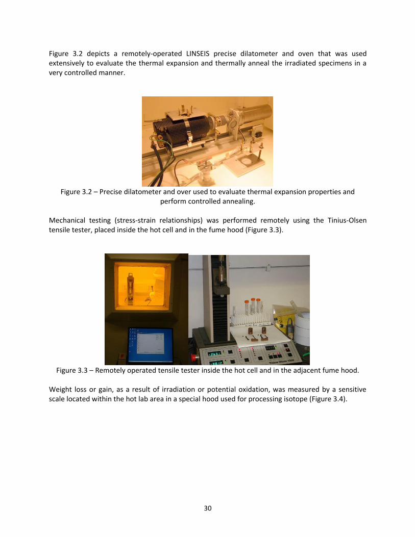
Figure 3.2 depicts a remotely-operated LINSEIS precise dilatometer and oven that was used extensively to evaluate the thermal expansion and thermally anneal the irradiated specimens in a very controlled manner.
Figure 3.2 – Precise dilatometer and over used to evaluate thermal expansion properties and
perform controlled annealing. Mechanical testing (stress-strain relationships) was performed remotely using the Tinius-Olsen tensile tester, placed inside the hot cell and in the fume hood (Figure 3.3).
Figure 3.3 – Remotely operated tensile tester inside the hot cell and in the adjacent fume hood.
Weight loss or gain, as a result of irradiation or potential oxidation, was measured by a sensitive scale located within the hot lab area in a special hood used for processing isotope (Figure 3.4).

31
Figure 3.4 – Four decimal sensitive scale in the isotope extraction fume hood used for weight loss/gain measurements of the irradiated LBNE materials.
Non-destructive ultrasonic techniques were used to measure changes induced by irradiation on the acoustic impedance of the different graphites. Acoustic impedance is directly related to the Young’s modulus of elasticity. These measurements were performed using the PANAMETRICS Epoch-4 system shown in Figure 3.5, where 1 MHz probes measured the ultrasonic velocities in the specimens by utilizing the reflection method.
Figure 3.5 – Ultrasonic system and fixture used in non-destructive testing of the specimens by measuring changes in ultrasonic velocities.
Finally, thermal conductivity was assessed indirectly from its relation to thermal resistivity, which was measured using the 4-point method shown in Figure 3.6. This phase of the study was performed at room temperature. Further measurements included radio-activity counters and a sensitive Ge detector for generating the gamma spectra of the irradiated specimens.

32
Figure 3.6 – Electrical resistivity apparatus used to measure thermal conductivity of the irradiated LBNE specimens in the BNL hot cell.

33
4.0 RESULTS
4.1 LBNE Graphites – Post-Irradiation Assessment
The four graphite grades that were irradiated with the 181 MeV protons at BLIP (IG-430, POCO ZXF-5Q, Carbone-2020 and SGL-7560) as well as the hexagonal Boron Nitride were all encapsulated and purged in argon gas. For potential comparison, it was planned to include samples of Toyo-Tanso IG-430 and POCO ZXF-5Q cooled directly by water and placed upstream of the argon-purged target cassettes. However, these samples were removed from the target array for proton energy budget reasons. 3D C/C composite was represented in both environments and since both graphite (Toyo-Tanso IG-43) and 3D C/C experienced similar damage in previous experiments, the effects of the environment at the achieved fluence level could be extrapolated from the 3D C/C composite performance. The effective beam energy irradiating the encapsulated graphite layers was estimated to be between 155-130 MeV, with the first layer of POCO graphite irradiated with 155 MeV protons and progressively degrading. The main objectives for the study of the four graphite grades were to:
1. Qualify and quantify the performance of these graphite grades in terms of resistance to
radiation damage when they are exposed to an equivalent proton beam damage that corresponds to about 1/5 year of running at LBNE (120 GeV and 0.7 MW beam). Due to the larger beam sport size in the actual BLIP test, the initial objective to run for an equivalent of 1 year of LBNE was not possible.
2. Perform a series of post-irradiation analyses focused on the effects of irradiation on key properties of graphite that play a pivotal role in target survival to beam-induced shock. Direct comparisons between the different graphite grades will identify the most promising candidates for further study and consideration for the multi-MW LBNE.
While graphite has been studied extensively due to its application in nuclear fission reactors primarily and as targets and other components in the kW-level power particle accelerators, it still remains a very intriguing material, due to its structure, which can vary significantly. As it was discussed in the previous section, weak bonds between parallel planes in its lattice make it weak along that direction and very anisotropic. Its specific structure is also responsible for the agglomeration of interstitial atoms during irradiation and the changes in some of its key properties. It was shown in Figure 1.9 that there is a dramatic change in the thermal conductivity (a very important property in target considerations) that takes place at very low levels of irradiation (fractions of DPA). While some of the lost conductivity is recovered with high temperature, the issue is of great concern to a multi-MW level target. 4.1.1. Thermal conductivity assessment
During the post-irradiation study of the four LBNE graphite grades, resistivity measurements that correlate with thermal conductivity, confirmed that for room temperature measurements the thermal conductivity of the irradiated graphite reduced by a factor of 6. While these measurements

34
need to be expanded for better statistics by modifying the measuring apparatus (future work), they are in line with the data shown in Figure 1.9. While previous data stem from irradiation with mostly thermal neutrons, it is expected that exposure to very energetic particles may have an even more dramatic effect that is not recoverable with thermal annealing by operating at higher temperatures. The higher rate of helium and hydrogen gas production as transmutation products trapped in the lattice structure may have a significant contribution on the degradation of thermal conductivity. In the course of the sensitivity study, the thermal conductivity of irradiated and annealed graphite at temperatures greater than the irradiation temperature the specimens experienced at BLIP, will be compared with specimens of similar fluence that are not annealed. The induced damage in graphite and its annealing process with temperature will be discussed in more detail in the next two sections, with dimensional stability as the method for assessing damage and its reversal. 4.1.2. Thermal stability and damage annealing
Changes in the thermal expansion property due to irradiation are very important mainly because: (a) thermal expansion is a property that is closely linked with thermal shock induced by the proton beam (σ ~ E · α · ΔT) and so changes in α will result in changes in the beam induced stress σ. In addition, changes in thermal expansion with increasing radiation exposure will result in dimensional changes of components surrounding and including the target that may have serious consequences. (b) observations on thermal stability and its relation to temperature can be directly related to changes in the lattice structure as well as damage reversal.
Following irradiation and the cool-down period, the CTE specimens of all four types of graphite were evaluated for changes in the thermal expansion property of the bulk material and for signs of volumetric changes that are expected to be observed when irradiation temperatures are below 300 °C. In addition, dimensional change measurements were used to compare how each graphite grades responds to the same irradiating field and to assess if annealing of induced damage is seen in these polyscrystalline graphites.

35
Figure 4.1 – Response of unirradiated POCO graphite over a series of thermal cycles.
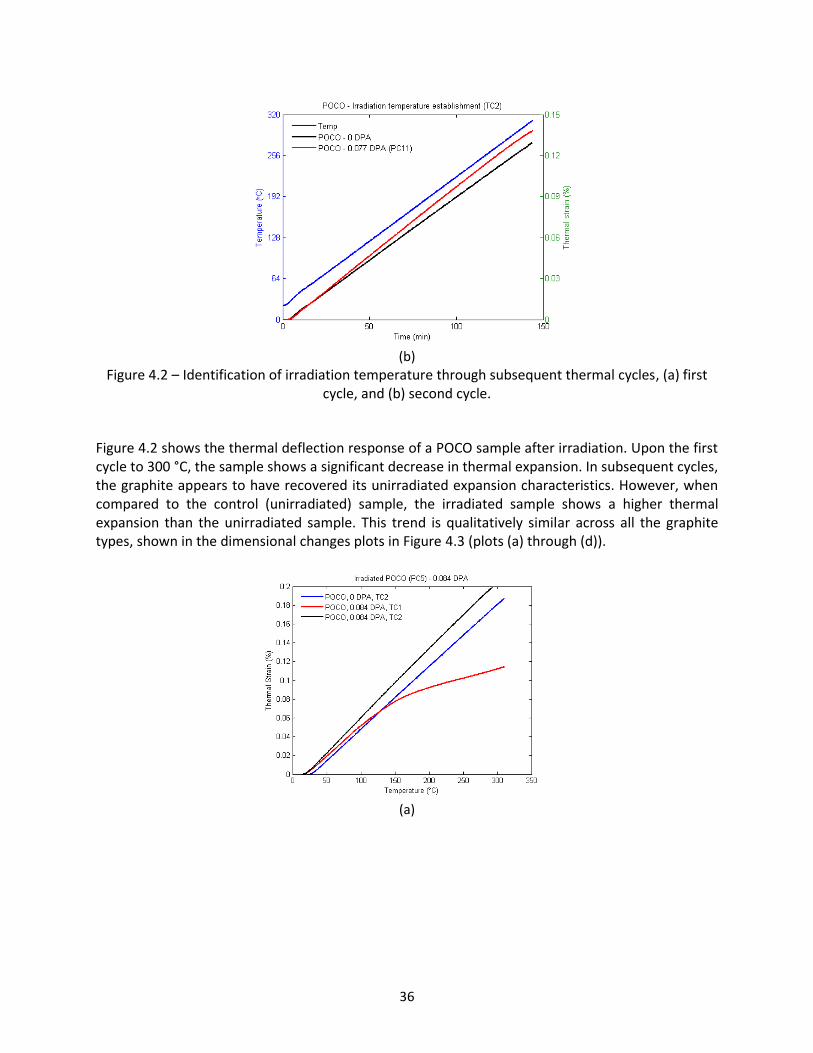
Figure 4.1 shows the stability of unirradiated POCO graphite over a series of thermal cycles. During the first cycle, there are inertia effects from the measuring apparatus. However, there is complete stability in the second and third cycle, as indicated by the coincident curves of TC2 and TC3. The latter trend is the same for the other graphite grades, demonstrating the stability of unirradiated graphites over a series of thermal cycles. The temperature at which the specimens were irradiated at can be inferred from the subsequent thermal cycle data. Figure 4.2 shows the first and second thermal cycle data of the linear expansion of POCO graphite over a temperature range of up to 300 °C. Results for an unirradiated specimen were compared to that of a radiated specimen at 0.077 DPA (PC11).
(a)
36
(b)
Figure 4.2 – Identification of irradiation temperature through subsequent thermal cycles, (a) first cycle, and (b) second cycle.
Figure 4.2 shows the thermal deflection response of a POCO sample after irradiation. Upon the first cycle to 300 °C, the sample shows a significant decrease in thermal expansion. In subsequent cycles, the graphite appears to have recovered its unirradiated expansion characteristics. However, when compared to the control (unirradiated) sample, the irradiated sample shows a higher thermal expansion than the unirradiated sample. This trend is qualitatively similar across all the graphite types, shown in the dimensional changes plots in Figure 4.3 (plots (a) through (d)).
(a)

37
(b)
(c)
(d)
Figure 4.3 – Dimensional changes of the graphite specimens, indicating irradiation damage in, (a) POCO, (b) C2020, (c) R7650, and (d) IG430.

38
From Figure 4.3, it is clear that for all graphite grades, the thermal strain curves of the annealed irradiated specimens are shifted above that of the unirradiated specimens, after the second thermal cycle up to 300 °C. The effect of irradiation damage on the dimensional change of POCO graphite, for specimens with varying DPA, is presented in Figure 4.4. After the second thermal cycle, all the thermal strain curves seem to align with each other, regardless of DPA. It is unclear as to why the behavior of specimens PC5 and PC11 for the first thermal cycle deviates from the general trend at temperatures greater than 150 °C (Figure 4.4(a)).
(a)
(b)
Figure 4.4 – Dimensional change response of unirradiated and irradiated POCO graphite with
varying DPA at (a) thermal cycle 1, and (b) thermal cycle 2.
Figure 4.5 compares all graphite grades at a particular DPA value to determine their dimensional response to thermal cycling. Clearly shown are the steeper curves of POCO as compared to the other graphite grades. IG430 and C2020 seem to display very similar dimensional change behavior.

39
(a)
(b)
(c)

40
(d)
Figure 4.5 – Overall graphite damage assessment through dimensional stability measurements, (a) 0.054 DPA TC1, (b) 0.054 DPA TC2, (c) 0.084 DPA TC1, and (d) 0.084 DPA TC2.
Figure 4.6 – Comparison of the change in CTE (20 – 300 °C) for BLIP irradiated graphite samples during two consecutive thermal cycles (open symbols: first cycle; filled symbols: second cycle).
Figure 4.6 summarizes the change in coefficient of thermal expansion for each of the graphite grades after annealing over two thermal cycles. The behavior in Figure 4.6 seems to be significantly different from past studies with graphite exposed to fast neutron irradiation. In particular, the CTE

41
under neutron irradiation was shown to increase at these low dose levels, contrasted with the decrease seen here during the first thermal cycle. In addition, it was previously shown that neutron irradiation induced damage was not completely reversed unless high annealing temperature were achieved (>1000 °C) compared to the lower annealing temperatures used in this study (300 °C). The CTE measurements from the second thermal cycle of this study are however consistent with the neutron irradiation damage results which indicate an increase in CTE. This can be explained by the interstitial atom annealing process. The initial decrease in CTE during the first cycle is due to the annealing of the interstitial atoms at temperatures higher than the irradiation temperature (as determined by the method shown in Figure 4.2). Once annealing has taken place during the first cycle, the graphite then shows an increase in CTE during the second cycle, indicating that the interstitial atoms mobile up to the annealing temperature have already been placed back in the lattice. As mentioned earlier, vacancies in graphite can only become mobile at temperatures greater than 1000 K (Kelly, 1996).
4.1.3 Damage reversal during annealing – Irradiation temperature assessment In addition to the coefficient of thermal expansion measurements, the damage annealing properties of the irradiated LBNE graphites are explored through a tedious, multi-stage annealing process in the experimental hot cell. The results of this study are important in that they can reveal the optimal operating temperature where most of the induced damage is annealed away by the temperature of the bombarded target. Through the annealing process, further verification and identification of the irradiation temperatures during the BLIP test are deduced. Unirradiated graphite annealing compared to irradiated damage reversal is shown in Figure 4.7.
Figure 4.7 – Annealing behavior of irradiated LBNE graphite (IG430) compared to unirradiated
graphite.
As evident from Figure 4.7, the unirradiated specimen remains stable during the process as compared to the irradiated specimen, which shows damage reversal when the annealing temperature goes over 200 °C (reduction in thermal strain at dwelling temperature). The temperature for the onset of damage reversal through annealing is an indication of the

42
temperature at which the specimens were irradiated at. This is in line with the assumption that up to the irradiation temperature, the specimen undergoes self-annealing. The irradiation temperature can be identified clearly in Figure 4.8 for C2020 graphite. The dimensional change of the irradiated C2020 specimen remains stable up to a temperature between 150 and 200 °C, after which damage reversal annealing is observed. This trend is consistent among the other graphite grades, where damage reversal annealing occurs when the annealing temperature is greater than the irradiation temperature. Figure 4.9 shows the multi-stage annealing behavior of heavily irradiated IG430 graphite over three thermal cycles. Clearly shown in Figure 4.9 is the continued damage reversal annealing that occurs during the first thermal cycle. However, due to the lower temperatures in the second and third cycles, no further annealing is observed.
Figure 4.8 – Multi-stage annealing of irradiated C2020 (0.07 DPA).
Figure 4.9 – Multi-stage annealing behavior of heavily irradiated IG430 (0.038 DPA) graphite.

43
From the above plots, the irradiation temperature of the specimens can be readily extracted by inspecting the temperature at which damage reversal annealing starts. The smaller the increment in dwelling temperatures, the more accurate the irradiation temperature estimate will be. As mentioned in Section 2.2, a 1-D radial heat transfer model was developed to theoretically estimate the temperature at which the specimens were irradiated at. Table 4.1 below shows the irradiation temperatures of some specimens, estimated from both the heat transfer model as well as from the multi-stage annealing plots.
Table 4.1 – Estimated irradiation temperatures from multi-stage annealing plots and 1-D heat transfer model.
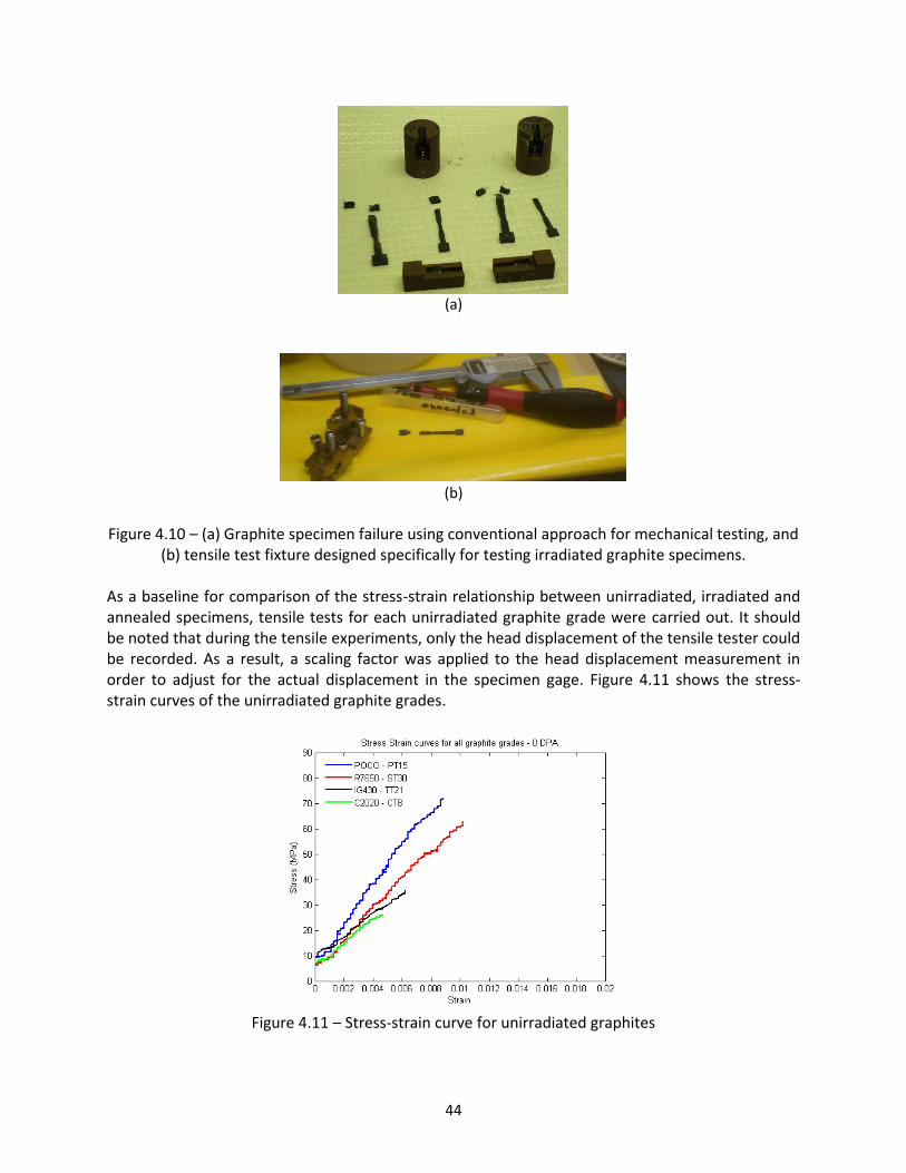
The result for specimen CC6 was obtained via the ultrasonic tests (Figure 4.20) discussed further in Section 4.1.5, while the h-BN specimen C11 (Figure 4.31(a)) is covered in Section 4.3. The 1-D model provides a good match for the estimated irradiation temperature for all the annealed tested specimens apart from specimen TT44. A potential explanation for the lower estimate of the 1D model is due to the contact region of the stainless steel capsule with the actual specimen (explained in more detail in Appendix B). Specimen TT44 lies very close to the point where the stainless steel capsule stops to make contact with the specimens. Therefore, a slight offset in the contact point calculation may lead to a higher irradiation temperature estimate for specimen TT44 (see Figure B.10 in Appendix B). From the results presented in the last two sections, it is clear that annealing has a significant impact on the thermal strain of the irradiated graphite grades. Irradiation is seen to lower the coefficient of thermal expansion but following annealing, the specimens recover their CTE to even a greater value than in their unirradiated state. As shown in the next section, annealing is also seen to recover the mechanical property change due to irradiation damage. 4.1.4 Mechanical testing of irradiated LBNE graphite For the mechanical testing of the irradiated LBNE graphite, a specific test fixture was designed for the graphite specimens (Figure 4.10(b)). Shown in Figure 4.10(a), is an irradiated POCO graphite specimen which was annealed prior to testing but failed near the loaded head, and not within the gauge, due to annealing-induced weakening (explained further in this section).
44
(a)
(b)
Figure 4.10 – (a) Graphite specimen failure using conventional approach for mechanical testing, and
(b) tensile test fixture designed specifically for testing irradiated graphite specimens. As a baseline for comparison of the stress-strain relationship between unirradiated, irradiated and annealed specimens, tensile tests for each unirradiated graphite grade were carried out. It should be noted that during the tensile experiments, only the head displacement of the tensile tester could be recorded. As a result, a scaling factor was applied to the head displacement measurement in order to adjust for the actual displacement in the specimen gage. Figure 4.11 shows the stress-strain curves of the unirradiated graphite grades.
Figure 4.11 – Stress-strain curve for unirradiated graphites

45
As shown clearly in Figure 4.11, POCO has the highest tensile strength and elastic modulus while C2020 is the weakest among the four graphite grades. The effect of annealing on unirradiated specimens is not expected to have any impact on the stress strain curve and this is shown in Figure 4.12. The plot shows data for unirradiated IG-430 graphite and no change in either ultimate tensile strength or elastic modulus is observed after annealing an unirradiated sample.
Figure 4.12 – Annealing of unirradiated IG-430 specimen showing no impact on the stress-strain
curve. Each irradiated graphite specimens were tested to investigate the effect of radiation damage on the tensile strength and elastic modulus. The effects of irradiation on the stress-strain curves for POCO, IG-430 and SGL R7650 are presented in Figure 4.13. It should be noted that only a few C2020 specimens could be successfully tested due to failure at the specimen head. As a result, the C2020 data are not shown.
(a)

46
(b)
(c)
Figure 4.13 – Stress-strain curves showing the effect of irradiation at varying DPA on tensile
properties of (a) POCO, (b) IG-430, and (c) SGL R7650 graphites. For all the graphite grades shown in Figure 4.13, there is a significant impact on the tensile properties as the specimens are irradiated. The ultimate tensile strength is shown to increase significantly while an increased stiffness is observed in the irradiated specimens (higher elastic modulus). However, it is difficult to differentiate the effects of DPA on the tensile properties for each of the graphite grades. The next step was to investigate how annealing changes the tensile properties of irradiated specimen. Figure 4.14 shows stress-strain plots for annealed irradiated POCO and IG-430 specimens.

47
(a)
(b)
Figure 4.14 – Effect of annealing of irradiated specimens on the stress-strain curve for (a) POCO, and (b) IG-430 graphite specimens.
For POCO graphite (Figure 4.14(a)), a change in the elastic modulus is observed when the irradiated specimen with the same DPA is annealed. The curve of PT47 (annealed) is less steep than that of PT31 (not annealed), thus revealing a lower elastic modulus. The ultimate tensile strength is seen to decrease for the annealed specimen, to a value much lower than the unirradiated specimen (PT15). Therefore, annealing of irradiated specimens decreases both the elastic modulus and the ultimate tensile strength. IG-430 graphites (Figure 4.14(b)) show similar trends. Specimens TT7 and TT44 received the same DPA, while TT44 was annealed before testing. Again, there is a significant decrease in the ultimate tensile strength and a decrease in the elastic modulus. However, the decrease in elastic modulus for the TT75 and TT4 IG-430 specimens due to annealing is less prominent, but a significant decrease in ultimate tensile strength is observed. Due to the higher DPA of TT75 and TT4, the specimens are expected to have been irradiated at a higher temperature and as a result, self-annealed more than specimens TT7 and TT44. Due to the lower irradiation of specimens TT7 and TT44, more damage is still present in the specimen before annealing. Therefore, a greater change in the properties is observed after annealing. It should be noted that the strain at

48
failure seems to be consistent across DPA and annealing temperature. While strength is compromised, the effective reduction in elastic modulus in thermal stress relations may be desirable for thermal shock absorption. A key finding from the above tests indicates that the enhancement in strength of the graphites due to irradiation does not coincide with the DPA levels. This is clearly shown in Figure 4.13. Again, the potential reason for the latter is the fact that specimens exposed to higher fluences (within one sigma), operated at higher temperatures, thus leading to real-time annealing through higher rate of interstitial mobilization. For the lower fluence specimens (lower irradiation temperatures), most of the damage is still present (interstitials between basal planes are still present and responsible for the strength increase of irradiated specimens). In order to compare the change in tensile properties due to irradiation and annealing, Figure 4.15 summarizes the percentage change in both ultimate tensile strength and elastic modulus as a function of DPA for each of the graphite grades.
Figure 4.15 – Tensile property changes as a function of DPA for all graphite grades.
In Figure 4.15, POCO specimens with the highest DPA exhibit a lower percentage change in ultimate tensile strength, while the change in elastic modulus hovers about the same value at all DPAs. Similar trends are observed for the IG430 and R7650 graphites, therefore confirming the nonconformance of enhancement in strength with DPA levels, as explained in the previous paragraph. The effect of annealing is clearly shown to result in a decrease in both elastic modulus and tensile strength for POCO and IG-430. An important difference between POCO and IG430 is in

49
the change in the elastic modulus due to irradiation. Figure 4.15 clearly demonstrates a larger percentage change (increase) in E for IG430 as opposed to POCO at all DPA levels. Therefore, for the same DPA damage, IG430 is expected to demonstrate a larger change in elastic modulus than POCO. However, through annealing, POCO is seen to recover most of its tensile properties and return close to the unirradiated state, as opposed to IG430. Therefore, the process of annealing will revert the elastic modulus and tensile strength of POCO closer to the value of its unirradiated as opposed to IG430. 4.1.5 Radiation-induced stiffness changes in graphite – ultrasound method From the mechanical testing, it was observed that with post-irradiation annealing to temperatures higher than the irradiation temperature, graphite lost the enhanced strength and stiffness it accumulated during irradiation and became weaker. This trend was verified by both the ultimate strength values of the specimens failing at the gage, and indirectly by the failure of specimens at their edges where compressive loads are applied to enable tensile testing. Therefore, in order to quantify the change in elastic modulus due to irradiation and post-irradiation annealing, non-destructive tests were performed using ultrasonic wave propagation techniques. The basic principle behind the non-destructive method is the propagation and reflection of ultrasonic waves (single wavelength or frequency) across the thickness of irradiated graphite. Based on the travel time and measured propagation length (twice the thickness of the specimen for the reflection method) of the waves, the wave velocity can be estimated. The elastic modulus E, is proportional to the square of the velocity and proportional to a constant factor related to density. Equations 4.1 and 4.2 show how the elastic modulus can be calculated from ultrasonic wave speed measurements.
(4.1)
(4.2)
where VT = Shear (transverse) velocity VL = Longitudinal velocity ρ = Density ν – Poisson’s ratio The determination of the combined influence of irradiation and temperature induced changes in the graphite stress-strain response will require a series of additional well controlled processes such as, (1) measurements of the shear wave velocities that will, in conjunction with the direct velocities, help determine Poisson’s ratio (Equation 4.2), (2) wave propagation principles through the porous structure of graphite to account for wave-pore interaction, and (3) quantification of contribution on dimensional changes from irradiation and temperature so that density variation can be accounted for. However, a first level evaluation, based on the changes of ultrasonic velocity through the

50
irradiated graphite material, will be a good indicator of changes in tensile properties due to irradiation and annealing to temperatures greater than the irradiation temperature. The system shown in Figure 3.5 (Panametrics EPOCH-4) with a 1 MHz probe was used to evaluate the irradiated LBNE graphites. Given that the irradiation temperature was less than 300 °C for the graphite in the LBNE study, the volumetric change occurring due to the anisotropy in the graphite crystal, is not expected to be large enough to overshadow changes in wave velocity. This was confirmed by measuring both the effective density and dimensions of graphite specimens prior to and after irradiation. Prior to the non-destructive damage assessment of the irradiated graphite, the baseline conditions were established by measuring unirradiated specimens so that percent changes can be established. Each irradiated specimen was measured for (a) activity in μCi so the relative radiation damage can be attributed to each measured sample, (b) the post-irradiation weight and thickness along which the ultrasound pulses will travel, and (c) ultrasonic wave travel time (two measurements for each specimen). Figures 4.16 to 4.18 present measurements of ultrasonic velocity changes in the CTE specimens of argon-purged POCO, IG430 and C2020 graphites. The activity of the CTE specimens has been measured and therefore, there is correlation of activity with the position of each specimen relative to the proton beam and to the accumulated damage. Because of the limited number of CTE specimens in each capsule, most of the specimens had already undergone thermal cycling to temperatures up to 310 °C for the dimensional stability and thermal expansion studies. This means that damage or change in the lattice associated with interstitials and up to the peak temperature of the thermal cycles has been removed by annealing. As a result, a stable trend up to the annealing temperature as a function of temperature, as discussed later in the section, is expected. Indicated in Figures 4.16 to 4.18, are the specimen numbers (PC for POCO, TC for IG430 and CC for C2020) and their history prior to the ultrasonic measurements (whether they have undergone thermal cycling or not). It should be noted that ultrasonic measurements were performed at room temperature.

51
Figure 4.16 - Measurements of the velocity of ultrasound in irradiated POCO graphite specimens. All
specimens except for PC16 have undergone thermal cycling to 310 °C.
Figure 4.17 – Measurements of the velocity of ultrasound in irradiated IG430 specimens. All
specimens except for TC29 and TC22 have undergone thermal cycling to 310 °C.

52
Figure 4.18 – Measurement of velocity of ultrasound change in irradiated C2020 specimens. All
specimens except for CC6 and CC5 have undergone thermal cycling to 310 °C.
By analyzing the data shown in Figures 4.16 to 4.18, important findings regarding the increase in elastic modulus due to irradiation and its retreat due to annealing are deduced. Based on the dimensional and weight measurements of the irradiated specimens, it is assessed that density changes due to irradiation are of the order of about 1-2%. The percent change of the apparent velocity is significant. However, as deduced from the data, the increase in velocity and thus the increase in bulk graphite material stiffness do not correlate with the fluence that the particular specimen has received. This is well in line with the damage mechanism in the graphite lattice. Since the process that leads to the increase in velocity and its retreat by temperature is directly linked to interstitials and their ability to mobilize, specimens that see the highest fluence also experience the highest temperatures which in turn imply that interstitial atoms that can be mobilized to find new positions in the lattice will do so. On the other hand, the effective stiffness of specimens that received smaller fluences should be higher as compared to the higher fluence counterparts, at room temperature. This is because the population of interstitial atoms between the basal planes which are directly responsible for the increase in velocity and effective stiffness, are not mobile at the lower temperatures (low fluence). This mechanism can explain the variation when the irradiation temperature, like in the case of the LBNE graphites, is below 300 °C. The fact that, following thermal cycling to temperatures up to 310 °C, the retreat of the velocity reaches a plateau, indicates that the contribution of vacancies that have been created by irradiation are yet to mobilize at these low temperatures. To help validate the assumption that the stiffness enhancement in the graphite (as seen by the change in ultrasound velocity) is larger with lower irradiation temperature, the results obtained during the tensile testing of the irradiated specimens in the previous section were closely analyzed. Remarkably the finding of the non-destructive approach show similar trends to the observations made during tensile testing in that increased strength by comparison is seen in target material away from the beam center where the irradiation temperatures are lower. As a preliminary assessment, the percentage change in the ultimate stresses of irradiated tensile specimens, as compared to the unirradiated state, are similar to those seen in the non-destructive tests. However, more specimens

53
are to be tested in order to accurately quantify the agreement. In addition, the softening and thus the retreat of the velocity seen in the non-destructive tests confirm the softening and fracture characteristics of tensile specimens annealed prior to stress-strain testing. Important findings and reinforcement of the assumed damage and annealing processes in irradiated graphites (including stiffness and strength deduction) are depicted in the results shown in Figures 4.19 and 4.20. In order to qualify the interstitial atom influence on increased stiffness (Young’s Modulus), two C2020 specimens irradiated at BLIP with similar fluences underwent multi-cycle annealing and upon return to room temperature, velocity increase measurements were made. Specimen CC12 with measured activity of 1,969 μCi prior to this study underwent thermal cycling to 310 °C while specimen CC6 (1,764 μCi) only experienced the irradiation temperature in beam. Annealing cycles were designed to progressively reach a peak temperature of 360 °C which was set as a limit to prevent oxidation. The start temperature for annealing was 140 °C which was deemed to be below the irradiation temperature followed by 160 °C annealing (closer to irradiation temperature). Figure 4.19(a) clearly shows that both specimens are dimensionally stable at 160 °C (CC12 is anticipated to exhibit this behavior up to 310 °C). The same exactly behavior was observed at 140 °C but not shown here since it is represented by the 160 °C level. At 200 °C annealing (Figure 4.19(b)), it is clear that restoration takes place in CC6 due to the mobilization of interstitial atoms, meaning that irradiation temperature must be above 160 °C and below 200 °C. For the annealing cycle in Figure 4.19(c) that reaches 320 °C (temperature just above the 310 °C CC12 had seen in the previous thermal cycle), both specimens exhibit dimensional changes (even though very minimal for CC12 due to the proximity of temperatures). Finally at 360 °C (Figure 4.19(d)), which consisted of two independent annealing thermal cycles (1st to 360 °C and dwelling for 2 hours before returning to room temperature and 2nd to 360 °C and dwelling for 8 hours), dimensional changes for both irradiated specimens can be clearly observed.
(a)

54
(b)
(c)
(d)
Figure 4.19 – Multi-stage thermal annealing of irradiated C2020 specimens for non-destructive
evaluation using ultrasound waves, (a) 160 °C, (b) 240 °C, (c) 320 °C, and (d) 360 °C.

55
Figure 4.20 – Ultrasound velocity recovery in irradiated/annealed C2020.
What is relevant in this multi-stage annealing is the percent velocity changes measured in between cycles at room temperature. Figure 4.18 depicts the trend for both irradiated specimens (CC6 and CC12). As seen for temperatures at and below the irradiation temperature of 160 °C, the percent velocity change does not vary for both. Due to interstitial mobilization above the irradiation temperature, a downward trend is exhibited by CC6 while CC12 remains unchanged until 310 °C (the temperature it experienced in prior thermal cycling). Also observed is that the effect of the eight additional dwell hours at 360 °C have minimal impact, given that the few interstitials able to mobilize at this temperature remain from the previous cycle. Similar findings were deduced in the extensive thermal stability analysis discussed earlier. 4.2 C-C Composite Post-Irradiation Assessment One of the primary objectives of the LBNE irradiation study at BNL BLIP was to assess the role the cooling environment plays in the observed accelerated damage and structural integrity in C/C composites and graphites. This severe effect has been previously observed in 2D and 3D C/C composite architectures as well as in IG-43 graphite, irradiated to fluences of about 5.0e21 p/cm2 with 200 MeV protons. Similar studies on 2D C/C showed the same behavior at lower fluence and beam energies. While in these studies cooling water were directly in contact with the target material, other studies with cooling environments other than water in direct contact showed similar behavior at higher fluences of about 10e21 p/cm2 with higher beam energies. While the beam exposure estimates for the BNL irradiation were to match an equivalent 1/5 of damage for the 120 GeV LBNE at 0.7 MW, the scope was also to cross this previously observed fluence for structural damage onset and compare the effect of the water environment with a different ambient environment surrounding the same material. A target capsule purged with argon gas and containing a similar array of 3D C/C specimens was used as the basis of comparison given that the water-cooled target materials and the argon-purged materials will see approximately the

56
same irradiation conditions (only a few MeV energy lower due to the beam degradation). It was also estimated that the irradiation temperature of the argon-purged C/C composite targets will be higher by several tens of degrees Celsius but both target arrays will be far below the oxidation temperature threshold. At the end of the 9-week irradiation period and cool-down period, the target enclosures were opened to reveal the condition of the irradiated specimens. Figure 4.21(a) shows the condition of the water cooled C/C array. Clearly the structural degradation that was observed in previous irradiation studies has occurred in this experiment, indicating that the beam exposure crossed the fluence for structural damage. Serious delamination is observed over the one sigma footprint of the irradiating beam. The specimens away from the one-sigma radius are intact indicating that while they were also exposed to both the beam and the water chemistry, they did not experience the degradation by the specimens at the beam center. Therefore, it is clear that the onset of structural damage depends on the combination of beam energy, irradiation temperature and fluence. For comparison, Figure 4.21(b) shows the conditions of 2D and 3D C/C composites as well as that of IG43 graphite following exposure to similar beam energy at the BNL BLIP but with slightly higher accumulated fluxes.
(a)
(b)
Figure 4.21 – (a) water-cooled LBNE 3D C/C composite samples following irradiation at BNL BLIP showing damage, (b) observed degradation in 3D C/C and 2D C/C composites in past BNL studies
with peak fluences slightly greater than those of the LBNE irradiation experiment.
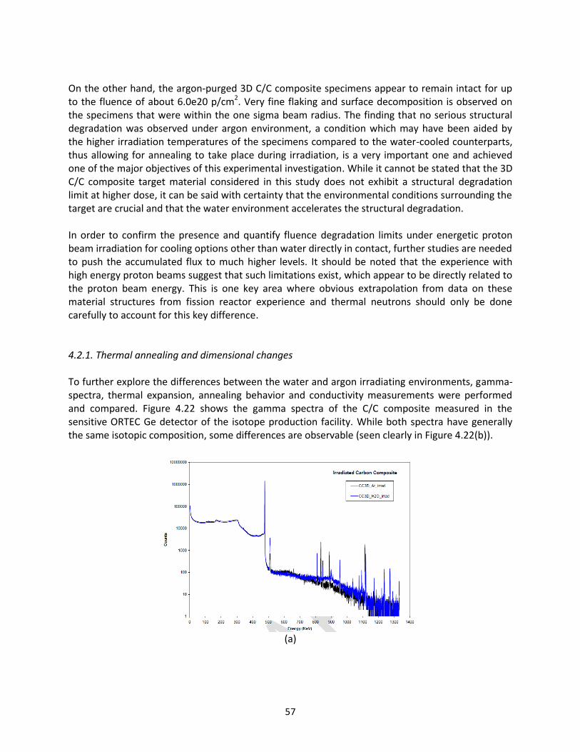
57
On the other hand, the argon-purged 3D C/C composite specimens appear to remain intact for up to the fluence of about 6.0e20 p/cm2. Very fine flaking and surface decomposition is observed on the specimens that were within the one sigma beam radius. The finding that no serious structural degradation was observed under argon environment, a condition which may have been aided by the higher irradiation temperatures of the specimens compared to the water-cooled counterparts, thus allowing for annealing to take place during irradiation, is a very important one and achieved one of the major objectives of this experimental investigation. While it cannot be stated that the 3D C/C composite target material considered in this study does not exhibit a structural degradation limit at higher dose, it can be said with certainty that the environmental conditions surrounding the target are crucial and that the water environment accelerates the structural degradation. In order to confirm the presence and quantify fluence degradation limits under energetic proton beam irradiation for cooling options other than water directly in contact, further studies are needed to push the accumulated flux to much higher levels. It should be noted that the experience with high energy proton beams suggest that such limitations exist, which appear to be directly related to the proton beam energy. This is one key area where obvious extrapolation from data on these material structures from fission reactor experience and thermal neutrons should only be done carefully to account for this key difference. 4.2.1. Thermal annealing and dimensional changes To further explore the differences between the water and argon irradiating environments, gamma-spectra, thermal expansion, annealing behavior and conductivity measurements were performed and compared. Figure 4.22 shows the gamma spectra of the C/C composite measured in the sensitive ORTEC Ge detector of the isotope production facility. While both spectra have generally the same isotopic composition, some differences are observable (seen clearly in Figure 4.22(b)).
(a)

58
(b)
Figure 4.22 – Gamma spectra comparison of irradiated 3D C/C composites in water and argon (0.03 DPA) for the LBNE study.
Given that dimensional stability of target materials during irradiation is a crucial parameter, an extensive post-irradiation study on the C/C composite specimens was performed to identify annealing behavior and associated temperature thresholds. Figure 4.23 depict thermal expansion behavior of irradiated C/C specimens in water and argon during the first of a number of thermal cycles and annealing conducted. The results of the first thermal cycle (indicated as TC1) are important because they reveal the temperature under which irradiation was taking place. It is the accepted notion that during low temperature irradiation, interstitials (atoms that are knocked off their lattice position) are mobile and can recombine or find new positions in the lattice. Therefore, it is expected that up to the irradiation temperature, self-annealing takes place due to interstitial movement to new lattice positions. As the temperature increases, interstitials that are further from such stable new positions are able to move towards them. It is thus anticipated that up to temperatures where vacancies can become mobile (>1000 K), the apparent annealing is due to interstitial atom mobilization and recombination. Figure 4.23 clearly demonstrate the progressive damage annealing as temperature increases. Important to note is the fact that when returning to a lower temperature where annealing was either complete, or most importantly incomplete due to insufficient annealing time, there is clear evidence that all the interstitial atoms that were being mobilized and had yet to find a new position, have reached equilibrium positions due to the higher energies (increased temperature) provided into the system. As expected, a higher irradiation temperature for the 3D C/C specimen that was placed in the argon purged capsule is shown clearly from Figure 4.23(b).

59
(a)
(b)
Figure 4.23 – Thermal cycling following irradiation of 3D C/C composites (0.03 DPA) in water and argon gas environments.
Figure 4.24 shows irradiated 3D C/C composite specimens in both water and argon environment undergoing multi-stage annealing. Figure 4.24(a) shows the first thermal cycle data, with specimen in argon (0.03 DPA) already annealed up to 310 °C. As a result, stable behavior is observed until about 310 °C, after which further annealing is observed. On the other hand, the specimen in water (0.072 DPA) was not previously annealed and therefore, the annealing process is clearly shown to start just below 100 °C. Figure 4.24(b) shows the second thermal cycle data and as expected, the specimen in water that underwent annealing from the first thermal cycle show stable dimensional changes up to about 400 °C. Some further annealing is observed above 400 °C, potentially due to the short dwelling time during the first thermal cycle, resulting in some partial annealing.
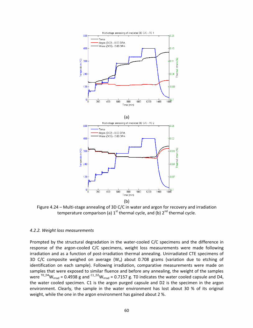
60
(a)
(b)
Figure 4.24 – Multi-stage annealing of 3D C/C in water and argon for recovery and irradiation temperature comparison (a) 1st thermal cycle, and (b) 2nd thermal cycle.
4.2.2. Weight loss measurements Prompted by the structural degradation in the water-cooled C/C specimens and the difference in response of the argon-cooled C/C specimens, weight loss measurements were made following irradiation and as a function of post-irradiation thermal annealing. Unirradiated CTE specimens of 3D C/C composite weighed on average (Wo) about 0.708 grams (variation due to etching of identification on each sample). Following irradiation, comparative measurements were made on samples that were exposed to similar fluence and before any annealing, the weight of the samples were T0_D4Wirrad = 0.4938 g and C1_D2Wirrad = 0.7157 g. T0 indicates the water cooled capsule and D4, the water cooled specimen. C1 is the argon purged capsule and D2 is the specimen in the argon environment. Clearly, the sample in the water environment has lost about 30 % of its original weight, while the one in the argon environment has gained about 2 %.

61
Multi-stage annealing to 475 °C was first performed followed by a second annealing directly to 475 °C for 4 hours and finally at 670 °C for 6 hours. Between each annealing cycle the specimen was weighed with the precise scale. The results are shown in Table 4.2 below.
Table 4.2 – Weight loss measurements of irradiated C/C composites
Water-cooled C/C Argon Environment C/C
Unirradiated mean weight 0.708 grams 0.708 gram
Temperature (°C) W(g) % W(g) %
RT(irradiated) 0.4938 -30.2542 0.7057 -0.03249
475 (1) 0.4834 -31.7232 0.7106 0.036723
475 (2) 0.4488 -36.6102 0.6837 -0.34322
670 0.401 -43.3616 0.6341 -1.04379
The weight gain due to irradiation was explored further by correlating the activity in the sample with the weight. As an example, the measured activity of the D2 specimen in argon was 981 µCi while its weight following irradiation was 0.7157 g. On the other hand, specimen D8, in the argon environment, was measured to have 3110 µCi of activity and weight of 0.7214 g. 4.2.3. Mechanical testing of 3D C/C composite As shown in Figure 1.7, there was the significant increase in strength for carbon fiber composites as compared to all graphite grades. For the LBNE material study, tensile specimens appropriate for the tensile testing machine housed within the BNL hot cells, were fabricated and irradiated. The FMI company that produced the 3D C/C composite advised allocating at least four fiber layers within the fracture gauge to avoid edge effects. This inevitably made the C/C composite specimens very strong over the gauge by comparison to other similar graphite tensile specimens. Subsequent testing using the normal apparatus and specimen holders revealed fracturing at the head due to stress concentration and weakening at the head. Figure 4.25(a) depicts failed C/C specimens at the head flares rather than the middle gauge. To circumvent the problem, a special holding fixture which operates by applying compressive load over a wider area on each of the specimen heads was only partially successful. This complex fixture is shown in Figure 4.25(b).
(a)

62
(b)
Figure 4.25 – (a) C/C composite specimen failure using a conventional approach for mechanical testing, and (b) tensile test fixture designed specifically for testing irradiated C/C composite
specimens. Preliminary results indicate that 3D C/C composites have superior strength to graphite. Figure 4.26 depicts C/C composite test results and comparison with high strength graphite (POCO). Because of grip slippage, the tensile stress in the gauge just exceeded 150 MPa, which is far above the level any graphite grade can reach. The actual stress of the unirradiated C/C is expected to reach 300 MPa while the irradiated counterpart expected to exceed that limit. As seen in Figure 4.26, the C/C composite is far more stable in its stress-strain behavior than graphite. To avoid the problems of grip slippage and failure at the head of the specimens, further studies will employ a three-point or four-point bending fixture to evaluate the flexural strength of the 3D C/C specimens, from which the tensile strengths may be derived.
Figure 4.26 – Stress-strain properties of C/C composite and comparison with POCO graphite.

63
4.2.4. Ultrasonic testing of 3D C/C composite As discussed in depth in the section dealing with graphite (4.1.5), non-destructive testing using 1 MHz ultrasonic pulses to assess changes in the modulus of elasticity E was carried out. While the method was very successful in assessing the effects of irradiation in graphite, it was difficult to apply the method in C/C composites. This is due to the structure of C/C where the array and layers of fibers scatter and diffuse the ultrasonic pulse which has a wavelength smaller to the diameter of each fiber. As a result, no accurate results regarding changes in elastic modulus via the ultrasonic method could be obtained for 3D C/C. 4.2.5. Thermal conductivity Using the 4-point resistivity measuring apparatus (Figure 3.6), preliminary results indicate that the thermal conductivity of the 3D C/C composite and in particular the specimens that experienced about 0.095 DPA of damage, reduced by a factor of about 3.2, as compared to an unirradiated specimen measured at room temperature. Further studies for better statistics on these measurements are ongoing and will be reported in an updated version of the report. 4.3 h-BN Post-Irradiation Assessment h-BN (Boron Nitride) was selected in this study because it is a close neighbor to graphite in terms of density, lattice structure and other properties (see Table 2.3). Furthermore, due to its excellent thermal and chemical stability, h-BN ceramics are used in high-temperature applications which provided an additional incentive to study the material alongside different graphite grades. However, it became apparent when the material was formed into specimens that it lacks structural integrity and that it is very fragile. As a result, only the CTE-type specimens were used in the irradiation and they were meshed with tensile specimens of IG430 graphite as shown in Figure 4.27. The h-BN specimens were placed in the last target holder of the series where it intercepted protons of about 130 MeV. The h-BN target holder was also purged with argon gas.
Figure 4.27 – h-BN specimen arrangement in the irradiation LBNE target array.
Following irradiation and from visual inspection and light handling, it became apparent that the specimens were even more fragile. Figure 4.28 shows one of the irradiated specimens which failed with extremely light handling within the hot cell. A possible explanation for the weakening of the material is attributed to the production of helium and hydrogen via the (n,α), (n,p), (p,α), and (p,p)

64
reactions. In the case of boron, there is a particularly large (n,α) cross section for the boron-10 isotope, which makes up approximately 20% of natural boron.
Figure 4.28 – Irradiated h-BN specimen ruptured with the slight handling in the hot cell.
Gamma spectra were obtained for irradiated h-BN specimens. Figure 4.29 shows the h-BN photon spectrum, while in Figure 4.30, h-BN is compared with the similar gamma spectra of C/C composite, irradiated with the same beam in both water and argon environment. Measurements were made with a very sensitive Ge detector with identical exposure time. It is interesting to see the increased isotopic activity in the h-BN as compared to the C/C composites.
Figure 4.29 – Photon spectrum of irradiated h-BN obtained by a sensitive Ge detector.

65
Figure 4.30 – Comparison of h-BN gamma-spectra with spectra of irradiated C/C composites in
water and argon, with the same proton beam. Because of the lattice structure of h-BN (similar to graphite), it is of interest to observe the dimensional changes as a function of radiation damage and temperature. Figures 4.31 and 4.32 show the following:
- h-BN has a negative thermal expansion for the temperature range studied (<800 °C) and it appears to continue on the negative side at even higher temperatures. In Figure 4.31(a), an irradiated specimen is compared to an unirradiated one. The stable dimensional change of the unirradiated specimen at each dwell temperature shows that no annealing is taking place. For the irradiated specimen, annealing is shown to start at about 180 °C. Therefore, similar to the 3D C/C and graphite specimens, the irradiation temperature is estimated to be between 160 and 200 °C. Figure 4.31(b) shows that there is still some un-annealed damage in the specimen.
- Irradiation induces changes in the expansion behavior in a similar way to the behavior in the direction parallel to the fiber planes of C/C but not similar to graphite, which is a close neighbor. This indicates that h-BN is highly oriented into parallel planes and not just its lattice.
Annealing behavior very similar to C/C composites in the direction of the fibers is observed. As seen in Figure 4.32 and following a multi-stage annealing cycle to 740 °C, the irradiated h-BN closely follows the unirradiated material from 400 °C to room temperature. The lower part of the curve indicates the return to room temperature. Interesting to note from Figure 4.32 is the shrinkage that is evident in the 0 DPA h-BN specimen at the dwell temperature of about 750 °C. This can also be depicted in Figure 4.31(a).

66
(a)
(b)
Figure 4.31 – Thermal expansion and annealing of irradiated h-BN (0. 095 DPA), (a) multi-stage annealing, and (b) second annealing cycle.

67
Figure 4.32 – Thermal annealing of damage in h-BN (0.095 DPA) achieved at temperatures below
400 °C.

68
5.0 DISCUSSION OF RESULTS AND CONCLUSIONS The BNL BLIP irradiation study was designed and executed in an effort to answer important questions on the feasibility of low-Z materials to be the target materials of choice for the multi-MW level LBNE experiment operating at 120 GeV proton beam energy. The matrix of low-Z materials under consideration for the LBNE experiment included graphite of advanced grades, carbon fiber composites (3D C/C) and hexagonal boron nitride. It is understood that during the operation of the LBNE experiment, the accumulated beam-induced damage in the target material will exceed the damage received to-date by protons on targets of similar experiments. An order of magnitude increases in the anticipated fluences and consequently radiation damage places serious uncertainties into the feasibility, performance and estimation of useful lifetime of the target. Experience in these low-Z materials from nuclear reactor operations should be used carefully and for reference only while extrapolation should be avoided due to the significant differences without informed adjustment to account for high energy effects of the irradiating species (energetic protons versus thermal neutrons). The key findings that are relevant to the posed questions from this investigation are summarized below:
1. The irradiation experiment at BNL BLIP provided enough proton fluence to create the damage observed in earlier experiments. Specifically, the onset of structural degradation and excessive damage observed in the LBNE 3D C/C composite irradiated while in direct contact with the BLIP cooling water (shown in Figure 4.21) was a convincing confirmation that the fluence sought was reached. Direct comparison with the encapsulated targets in the argon environment could be made as well as with results from previous studies.
2. The finding and confirmation that there is damage in the target when in direct contact with the BLIP cooling water indicates that for these energies (118-200 MeV), the structural degradation fluence of about 6e20 p/cm2 exists and will limit the performance. As pointed out in the body of the report, recent studies performed under similar conditions with 30 MeV, observed limiting fluences that are of the order of 1019 p/cm2. Graphite target operational experience from other accelerators such as LANCE, Triumph, and PSI with higher energies, stumbled upon limiting fluences higher than those identified at BNL. For example, for the water cooled pyrolytic graphite targets at LANL intercepting 800 MeV protons, the damage degradation limiting fluence was identified as 2.0e21 p/cm2, approximately an order of magnitude higher than what was seen at BNL for 200 MeV protons. It can therefore be concluded that the limiting fluence in graphite and C/C is proton energy dependent, while the damage is aided/accelerated by the water chemistry at the interface (radiolysis of water into H and chemically active nascent O by the proton beam). As proton energy is increased, its higher energy spreads out the damage throughout the target. On the other hand, lower beam energy results in highly localized damage close to the target’s surface, which confirms the structural damage fluence limit trends from previous experiments. For LBNE, where the proton energy is 120 GeV, the fluence threshold under water cooling should be higher than the BNL threshold of about 6e20 p/cm2. Precise
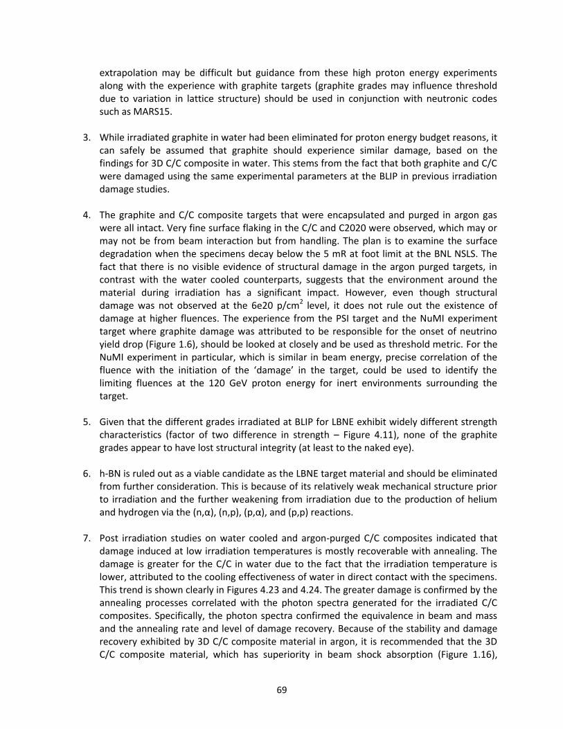
69
extrapolation may be difficult but guidance from these high proton energy experiments along with the experience with graphite targets (graphite grades may influence threshold due to variation in lattice structure) should be used in conjunction with neutronic codes such as MARS15.
3. While irradiated graphite in water had been eliminated for proton energy budget reasons, it can safely be assumed that graphite should experience similar damage, based on the findings for 3D C/C composite in water. This stems from the fact that both graphite and C/C were damaged using the same experimental parameters at the BLIP in previous irradiation damage studies.
4. The graphite and C/C composite targets that were encapsulated and purged in argon gas were all intact. Very fine surface flaking in the C/C and C2020 were observed, which may or may not be from beam interaction but from handling. The plan is to examine the surface degradation when the specimens decay below the 5 mR at foot limit at the BNL NSLS. The fact that there is no visible evidence of structural damage in the argon purged targets, in contrast with the water cooled counterparts, suggests that the environment around the material during irradiation has a significant impact. However, even though structural damage was not observed at the 6e20 p/cm2 level, it does not rule out the existence of damage at higher fluences. The experience from the PSI target and the NuMI experiment target where graphite damage was attributed to be responsible for the onset of neutrino yield drop (Figure 1.6), should be looked at closely and be used as threshold metric. For the NuMI experiment in particular, which is similar in beam energy, precise correlation of the fluence with the initiation of the ‘damage’ in the target, could be used to identify the limiting fluences at the 120 GeV proton energy for inert environments surrounding the target.
5. Given that the different grades irradiated at BLIP for LBNE exhibit widely different strength characteristics (factor of two difference in strength – Figure 4.11), none of the graphite grades appear to have lost structural integrity (at least to the naked eye).
6. h-BN is ruled out as a viable candidate as the LBNE target material and should be eliminated
from further consideration. This is because of its relatively weak mechanical structure prior to irradiation and the further weakening from irradiation due to the production of helium and hydrogen via the (n,α), (n,p), (p,α), and (p,p) reactions.
7. Post irradiation studies on water cooled and argon-purged C/C composites indicated that
damage induced at low irradiation temperatures is mostly recoverable with annealing. The damage is greater for the C/C in water due to the fact that the irradiation temperature is lower, attributed to the cooling effectiveness of water in direct contact with the specimens. This trend is shown clearly in Figures 4.23 and 4.24. The greater damage is confirmed by the annealing processes correlated with the photon spectra generated for the irradiated C/C composites. Specifically, the photon spectra confirmed the equivalence in beam and mass and the annealing rate and level of damage recovery. Because of the stability and damage recovery exhibited by 3D C/C composite material in argon, it is recommended that the 3D C/C composite material, which has superiority in beam shock absorption (Figure 1.16),

70
thermal conductivity (Figure 1.9) and strength over graphite (Figure 1.7) (almost 5 times the strength of graphite), should be one of the prime candidates for the multi-MW LBNE. However, this holds true only when the material is under vacuum or inert gas environments.
8. It became apparent from the post-irradiation analysis of the different graphite grades that graphite is still an intriguing structure. They have great variability of performance across the different grades and even within the grade (especially true with amorphous graphites which appear to offer the greater graphite strength). The study reveals that unirradiated POCO and SGL-R7650 graphites both exhibit higher tensile strengths and elastic modulus than the other grades (Figure 4.11). The strength and elastic modulus increased further (Figure 4.13) for both POCO and SGL-R7650 after the specimens were irradiated. However, the percentage increase in tensile properties of IG430 was observed to be the larger than both POCO and SGL-R7650 (Figure 4.15). C2020 graphite is the weakest among the four graphite grades (Figure 4.11). In terms of dimensional stability, POCO and SGL-R7650 showed greater dimensional changes after irradiation, while IG430 was the most stable of the graphites (Figure 4.5). Damage reversal took place when irradiated specimens were annealed at temperatures greater than the irradiation temperature. Following annealing, the CTE values of the irradiated specimens were increased above the value of the unirradiated specimens. This was shown to be consistent across all graphite grades (Figure 4.6). Annealing also led to the tensile property recovery of both IG430 and POCO. POCO displayed a greater percentage recovery than IG430 (Figure 4.15). The latter is likely due to the fine-grained structure of IG430 that provides sinks for interstitial and places for transmutation products such as He and H to collect – this in turns restrict full recovery through annealing. The competing effect of the larger damage reversal effect in POCO’s tensile properties through annealing and the dimensional stability of IG430, make these two graphite grades potential candidates for the target material of the multi-MW LBNE. It should be noted that more specimen testing is planned to obtain better statistics to solidify the understanding of the current trends observed for the graphite grades.
9. The ultrasonic tests conducted were successful for the graphite grades but was not possible for the C/C composite, due to interference of the carbon fibers with the reflection of the ultrasonic waves. The ultrasonic tests for the graphite grades revealed similar trends observed from the tensile mechanical tests, with further testing planned.
Finally, in regards to which target materials can support the 120 GeV 0.7 MW LBNE, it can be stated from a radiation damage perspective, that for 1/5 year operation of the experiment at that power level, the 3D C/C and all four graphite grades can satisfy that requirement. It should be noted that the latter conclusion does not account for thermal shock behavior of the graphites and composite. The limitation in using 3D C/C is that it cannot be in direct contact with water for cooling purposes. As for the graphites, the prime candidates should be the POCO and IG430 graphite for the reasons mentioned above (point 8).

71
6.0 FUTURE WORK This report provides the initial findings from the BNL BLIP tests for potential LBNE target materials. To strengthen the understanding of the graphite grades’ behavior due to radiation damage and damage reversal annealing, further studies are required. Since untested irradiated specimens are available, more tests can be carried out to fully understand the trends observed and provide a comprehensive comparison of each of the graphite grades. The future studies that will be carried out are listed below.
1. Three and four point flexural test: From Section 4.2.3, tensile tests of 3D C/C specimens resulted in grip slippage and failure at the head. The tensile testing fixture proved to be unsuccessful and as a result, a three-point and four-point flexural tests are planned for the 3D C/C specimens. These fixtures are currently being designed and flexural tests are planned in the near future. Tensile strengths may then be inferred from the flexural strength measurements.
2. Ultrasound tests: Further ultrasonic tests are required in order to confirm the trends observed from tensile measurements, in regards to elastic modulus recovery prior to and after annealing of the irradiated specimens. Shear wave velocity measurements are also required to estimate any change in the Poisson’s ratio. The ultrasonic testing technique will be developed further in order to be able to quantify density changes as well as account for the porosity difference between each of the graphite grades.
3. Thermal conductivity measurements: As mentioned in the report, more thermal conductivity measurements are needed to quantify any changes due to radiation damage and annealing. A technique to measure resistivity at elevated temperatures will be explored.
4. Tensile tests: More statistics on tensile data are required to fully understand the tensile property changes due to radiation damage and annealing for all the graphite grades. So far, only trends in POCO and IG430 can be deduced. More tensile tests are required for C2020 and SGL R7650.
5. Increased flux: Finally, the potential to irradiate new targets to much higher accumulated proton flux will be valuable. This will help better quantify any fluence degradation limits for each of the target materials. Moreover, since the initial test plan to simulate one year of the LBNE experiment damage was not achieved, the next phase will aim to push irradiation flux in order to achieve much higher DPA levels. This will also give insight of the property response of the materials at higher irradiation temperatures.

72
APPENDICES
Appendix A: Experimental Design and Damage Assessment Appendix B: Thermo-Mechanical Analysis Appendix C: Experiment Safety Considerations and Facility Compliance

73
Appendix A: Experimental design and damage assessment
(MARS-15 - N. Mokhov)
120-GeV proton beam with σx= σy= 1.1 mm 2.0e13 p/s × 2.0e7 s/yr = 4.0e20 p/yr Target: POCO Graphite, 1.78 g/cc 47 × (15 ×6.4 ×20 mm)
Figure A.1 - NuMI target configuration (POCO graphite segments) and 120 GeV protons

74
Figure A.2 – NuMI Target DPA
Figure A.3 - NuMI target power density peak = 180 W/g

75
Figure A.4 - BNL Target - 165 MeV
Figure A.5 - BLIP equivalent Peak: 1.6 dpa/yr - POCO graphite

76
Figure A.6 - POCO graphite energy density Peak: 395±5 W/g
Figure A.7 - NuMI vs. BLIP DPA

77
STUDY OF THE ACTUAL BNL TARGET ARRAY
Figure A.8 - BLIP Target Array (1st iteration)
Calculated: particle fluxes, power density, DPA, hydrogen and helium gas production and residual
dose for two-dimensional distributions along and across the beam.
Figure A.9 - BLIP Proton Flux
Figure A.10 - Proton Flux in 1st (POCO) and 11th (AlBeMet) Samples
Figure A.10 – Proton Flux in 1st (POCO) and 11th (AlBeMet) specimens

78
Figure A.11 - DPA in BLIP target arrangement (1st iteration)
Figure A.12 - DPA in 1st (POCO) and 11th (AlBeMet) specimens after 9 weeks of irradiation - Peak:
0.11-0.13 dpa in 1st to 8th graphite specimen, 0.13 dpa in hBN, 0.06 dpa in Be, and 0.3 dpa in
AlBeMet.

79
Figure A.12 - Hydrogen Gas Production
Figure A.13 - Hydrogen in 1st (POCO) and 11th (AlBeMet) specimens (Peak: 2.5e12 cm-3s-1)

80
Figure A.14 - Helium gas production
Figure A.15 - Power density distribution - peak grows from 113 to 123 W/g from 1st to 8th graphite
specimen, 118 W/g in h-BN, and 112 W/g in Be and AlBeMet.

81
Figure A.16: Residual dose (~50 Sv/hr on BLIP Target Holder Box)

82
Appendix B: Thermo-Mechanical Analysis
B.1: Experimental Layout and BNL BLIP Beam Parameter Space
Figure B.1: LBNE target configuration at BNL BLIP
Figure B.2: Power density distribution

83
B.2: Numerical Analysis – Irradiation Temperature Assessment The primary focus of the experimental design, given the beam parameters and cooling capabilities at the BLIP target area, was to estimate the temperatures that can potentially be reached under vacuum conditions. The temperatures would be estimated based on the energy deposition values obtained by MARS-15 (peak of 400 W/g). Figure B.2 shows MARS estimates of energy deposition on graphite targets for the BLIP configuration based on an incoming beam with σx = σy = 4.233 mm. In the process of configuring the LBNE target experiment at BLIP, a comprehensive study was undertaken to estimate the temperatures in the target materials and the assembly. This was driven by two primary reasons, namely temperature conditions for safe operations at BLIP and the desired irradiation temperatures that will be within the range of target temperatures during actual LBNE target operations. In previous BLIP target tests, attempts have been made to estimate target temperatures during irradiation and due to the BLIP target space configuration, in-situ measurements with thermocouples is not feasible. However, in-situ BLIP temperature assessment tests have been performed using a special thermal paint on stainless steel and aluminum target disks. Crucial in estimating irradiation temperatures, is the “quantification” of the conductance between surfaces that controls the heat path. Due to the outer pressure buckling inward, the windows (both upstream and downstream), are expected to stay in contact with part of the face of the target layer next to it, which the analysis accounted for. However, the exact value is still elusive. As a conservative estimate, the analysis employed 200 W/m2-K and several sensitivity studies were performed. Results are shown for 1000 W/m2-K (maximum between targets and windows) to compare with the baseline. As will be shown later, the temperature in the middle of the graphite for the conservative case reaches 1400 °C. When the conductance is 5 times that of the conservative case, the peak temperature reaches about 450 °C. The operating temperatures with the BLIP beam on were confirmed with detailed finite element analysis. In addition, the temperatures predicted by the analyses were confirmed by an indirect method; based on the temperature of carbon composites materials when the annealing of damage induced by irradiation started, which signifies the temperature at which the material was irradiated. The irradiation temperatures were deduced from post-irradiation analysis and annealing tests of carbon composites irradiated at BLIP and tested in the hot cells of Building 801. Figure B.3 shows in-situ temperature test results obtained at BLIP using a special thermal paint to identify the operating temperatures. Also shown are temperature predictions from analysis that was performed prior to the test, which confirmed the observed temperatures, based on the BLIP water cooling conditions.

84
Figure B.3: In-situ temperature measurement
For the LBNE BLIP target test where graphite and carbon composite were primarily tested, the targets have the exact same configuration (directly cooled by the BLIP water with similar arrangement) as the tests that have been previously conducted at BLIP, while the rest of the targets are encapsulated in stainless steel to avoid direct contact with water. While the temperatures in the water cooled targets are expected to be quite low, as observed in prior tests with approximately same BLIP beam parameters, the temperatures in the encapsulated materials were of interest. Shown in Figure B.3 is the target assembly with both the water cooled

85
and the encapsulated targets. It should be noted that due to the pressure at a depth of 30 ft of water, the thin stainless steel windows are pushed inward and thus in contact with the enclosed specimens. This provides a heat path to the water in the channels. The process of establishing the encapsulated material temperatures for the LBNE-BLIP tests consisted of the following:
Using the BLIP beam parameters (energy and beam size) and MARS calculations to give the power density or energy deposition throughout the target assembly (including target irradiation damage as well as He and H production in the targets). References 1 and 2 provide the details of the MARS studies related to this BLIP run.
Very detailed but independent thermal/structural analyses based on the energy deposition in the specimens as obtained by MARS for the BLIP target configuration. The parallel studies were performed at Fermilab and at BNL.
Two sets of analyses were performed in the process and are characterized by the following:
Scoping Study I: BLIP beam energy at 165 MeV and a very tight beam spot (σx = σy = 4.233 mm). This condition while incompatible with BLIP isotope production was analyzed to explore the levels of material irradiation damage that can potentially be achieved during the same 9-week period.
STUDY II: Actual LBNE configuration and actual BLIP test beam parameters of 181 MeV and σx = 8.92mm and σy = 6.79mm, which represents the running conditions or the test at BLIP.
In the scoping Study I, estimates of energy deposition in the target materials were made using MARS based on BLIP beam parameters of 165 MeV and σx = σy = 4.233 mm. This tight spot size was desired in order to induce the same level of damage over the 9-week irradiation period at BLIP as one year of target operation of the LBNE experiment. Shown in Figure B.2 are the results of the original MARS analysis indicating a peak power density in the target assembly of 310 W/gram. These energy deposition results were used in the two parallel analyses (Fermilab and BNL) to obtain peak temperatures in the target materials that are encapsulated. In both analyses, the worst-case scenario of temperature estimate was sought that will be seen by the middle of the three-layer dog-bone specimens which do not come in contact with the capsule windows. Figure B.4 depicts the detailed finite element model used in the Fermilab study, which exactly replicates the LBNE-BLIP target specimen configuration within the capsule (filler material covering the 4 quarters between the target edges and the rim are not shown).

86
Figure B.4: Fermilab LBNE encapsulated target model for thermal/structural analysis
The BNL model, shown in Figure B.5 and B.6, incorporated thermal contacts between the target layers and between targets and capsule windows as well as target capsule and frame. It also incorporated the expected pressure on the capsule windows that will be experienced during the BLIP test and therefore allowing the bulging-in of the thin capsule windows and the contact with the target materials.
Figure B.5: LS-DYNA model

87
Figure B.6: Model indicating layers in contact
For this extreme state where the targets are under vacuum inside the capsule and for minimal conductance value of 200 W/m2-K, the two independent analyses produced very similar results in terms of peak temperature. Figures B.7 and B.8 show the comparison between the parallel studies.
Figure B.7: Extreme case BNL analysis temperature prediction (surface conductance of 200 W/m2-K
and vacuum)

88
Figure B.8: Extreme case Fermilab analysis temperature prediction (surface conductance of 200
W/m2-K and vacuum)
The peak temperatures at the center of the middle graphite dog-bone specimen for the extreme case (minimum conductance value of 200 W/m2-K) reached about 1400 °C. However, more realistic values of conductance between the heat transfer surfaces showed that maximum temperatures are around 450 °C (shown in Figure B.9).
Figure B.9: Temperature estimated by the BNL analysis for the window (or shell of capsule), target
material and the middle graphite target layer (right) under the conservative energy deposition of
400 W/g and optimistic conductance of 1000 W/m2-K for the very tight beam spot (σx = σy = 4.233
mm).

89
Therefore, based on the two parallel studies, it was assessed that the temperatures in the very center of the middle layer of the targets in the capsule will be somewhere between 450 and 1700, by taking into account the most extreme conditions of beam tightness, minimum conductance through contact surfaces and vacuum. Such temperature range is tolerated by the materials chosen in this study. However, the BLIP beam parameters for the actual test are different than those of the STUDY I parameters, where the maximum target damage possible at BLIP was envisioned as a representative measure of the damage anticipated in a cycle run of the LBNE experiment. Most importantly, the beam is broader than the optimally desired one. Beam profile measurements from BLIP in January of 2010 (beginning of 2010 run) at 117 MeV revealed that the beam is characterized by a spot size with σx = 8.92mm and σy = 6.79mm (FWHM values from BLIP phosphor-image in January were 16mm vertical and 21mm horizontal). This is approximately the same as the beam spot from the 2009 BLIP run. Based on this broader beam size and the target composition originally envisioned for the LBNE BLIP irradiation shown in Figure 2.10 of the main text, the required incoming energy for the configuration was estimated to be 188 MeV. Based on the new energy and the broader beam spot that the BLIP irradiation test will be conducted at (σx = 8.92mm and σy = 6.79mm), new MARS analyses were conducted to deduce the power densities expected in all the target materials. All the details of the MARS analysis that is closely representing the BLIP actual irradiation experiment are included in Reference 3. The most important thing to note here is that the peak power density in the target array is reduced by a factor of 3. In particular, the peak energy density is now 123 W/g in the graphite target material instead of the 310 W/g originally estimated for the extreme BLIP beam parameters. Thermal analyses using the energy deposition of the actual experiment were performed both at Fermilab and at BNL. A reduction in the temperatures, as compared to the original scoping study based on the 400 W/g peak power density, both for the target materials and the shell (or windows) of the capsules enclosing the target materials was observed. Both independent analyses (Fermilab and BNL studies) showed comparable anticipated peak temperatures during the actual run. Peak temperatures in the encapsulated target material (graphite) are expected to be in the range of 180-320 oC while temperatures in the thin stainless steel shell enclosing the targets in the range of 100-180 oC. In an effort to ensure that the exit energy of the LBNE targets is compatible with what is required by the isotope targets (112.65 MeV) and given that the BNL Linac energy is 181 MeV, some of the target materials originally included in the matrix were removed. A graphite layer from the front of the target array (water cooled) was removed along with the encapsulated AlBeMet and Beryllium targets that were placed in the downstream end of the array. Their ~3mm depth in the final configuration (see Fig B.3) is occupied by the cooling water flowing past the target arrangement. MARS analyses were performed for the final configuration and beam energy of 181 MeV and showed very little change in the estimates of energy deposited in the targets. In addition, the beam spot measured at the start of the 181 MeV operations which enabled the LBNE target irradiation and the isotope production was broader than the baseline (beam spot measured in January 2010 at 117 MeV). The beam profile at the beginning of the BLIP LBNE test had σx = 10.6 mm and σy = 6.79 mm. This implies that the estimated peak power densities and temperatures should represent upper bounds for the actual experiment.

90
To further estimate the irradiation temperatures of the specimen, a simplistic one dimensional axisymmetric heat transfer model was developed. Using the energy deposition from MARS and the calculated gap conductance, the 1-D heat transfer model approximates the axial temperature distribution of the specimens, treated at 1 mm wide annular rings. The transverse heat transfer is not taken into account. For each ring, the gap conductance value was calculated, while the contact area was determined by deflection and volume/pressure calculations. As mentioned earlier, due to the outer pressure buckling inward, the stainless steel windows are expected to stay in contact with part of the face of the target layer next to it. The radial temperature distribution for the targets in argon purged capsules is shown in Figure B.10. These results may represent a slight overestimation of the peak irradiation temperature due to the fact that transverse heat transfer was neglected.
Figure B.10 – Radial temperature profile of BLIP target specimens using 1D heat transfer model.

91
Appendix C: Experiment safety considerations and facility compliance
C.1: LBNE Target Radionuclide Production Analysis using MCNPX
This section contains a summary of the results from the MCNPX analyses performed to assess the radionuclide production from the interaction of the 181 MeV protons with the LBNE target configuration. Based on the configuration shown in Figure C.1, target layers were removed from the assembly prior to the start of the irradiation in order to meet the exit energy requirement resulting in additional volume of water intercepting the proton beam.
Figure C.1: LBNE target arrangement used in the MCNPX calculations summarized in this Appendix. Dark blue represents the additional water flowing past the target array. Light blue spaces indicate
water in the original channels.
The MCNPX models used closely reflect the actual configuration (including target materials, beam windows and the water layers). Production of nuclides from the entire LBNE target assembly was noted. In an extra step, the contribution of the nuclides of interest from the water volume intercepting the beam was isolated and quantified. Table TC.1 below lists both the water contribution and the total number of nuclides produced per proton. The calculations of production rate that follow are focused on the water contribution. Using the output from the MCNPX analysis, the relation below and the BLIP beam current, the production rates for specific nuclides were quantified.
2/1
]2[ln
NN
where N is the nuclides produced per incident proton on the target array (produced by MCNPX). Appendix A contains the tallying of the water radionuclide contribution from the complete MCNPX analysis.

92
From the entire spectrum of nuclides produced by the interaction of the 181 MeV with the target array, attention was focused on a short list and in particular those that are expected to be contributing to the dose registered around BLIP. The table below depicts the radionuclide, its half life and the number of nuclides produced per incident proton
Table TC.1 – Total number of nuclides per proton
Nuclide Half-life Nuclides per proton from water in LBNE targets
TOTAL # of nuclides per proton [targets + water]
O-14 70.6 s 7.50 e-05 7.50 e-05
O-15 122.2 s 1.51 e-03 1.52 e-03
N-13 9.97 min 2.90 e-04 3.01 e-04
C-11 20.3 min 6.67 e-04 5.45 e-03
Be-7 53.28 days 2.71 e-04 2.61 e-03
Based on the BLIP average beam current of 104 μA, which corresponds to about 6.4945e14 protons/s and the equivalence of Curie to disintegrations per second [1 Curie = 3.7 1010 dis/s], the following estimates are deduced:
Table TC.2 – Radionuclide activity per proton
O-14 1.99 · 10-17 Ci/proton
O-15 2.32 · 10-16 Ci/proton
N-13 9.07 · 10-18 Ci/proton
C-11 1.02 · 10-17 Ci/proton
Which, for the operating beam current of 104 µA translate to a production rate from the LBNE target water is:
Table TC.3 - Radionuclide Production Rate from LBNE Target Water
O-14 1.30 · 10-2 Ci/sec
O-15 1.50 · 10-1 Ci/sec
N-13 5.89 · 10-3 Ci/sec
C-11 6.66 · 10-3 Ci/sec

93
C.2: Water contribution to radionuclide production BLIP LBNE Targets - 181 MeV Protons Reading history tape written by MCNPX 03/29/10 16:55:13 181 MeV Protons - distribution of residual nuclei
z = 2 n = 4 7.50000D-06 0.2582 all n 7.50000D-06 0.2582 z = 3 n = 3 4.01500D-04 0.0353 n = 4 2.69000D-04 0.0431 n = 5 1.20000D-05 0.2041 n = 6 1.00000D-06 0.7071 all n 6.83500D-04 0.0270 z = 4 n = 3 2.71000D-04 0.0429 7Be n = 4 2.15000D-05 0.1525 n = 5 1.95000D-04 0.0506 n = 6 5.15000D-05 0.0985 10Be n = 7 1.00000D-06 0.7071 all n 5.40000D-04 0.0304 z = 5 n = 3 2.00000D-05 0.1581 n = 4 4.00000D-06 0.3536 n = 5 4.59000D-04 0.0330 11C n = 6 6.52000D-04 0.0277 n = 7 3.00000D-05 0.1291 n = 8 2.50000D-06 0.4472 14C all n 1.16750D-03 0.0207 z = 6 n = 3 9.50000D-06 0.2294 n = 4 7.25000D-05 0.0830 n = 5 6.67000D-04 0.0274 n = 6 2.55641D-03 0.0140 n = 7 7.64500D-04 0.0256 n = 8 2.17500D-04 0.0479 n = 9 1.00000D-06 0.7071 all n 4.28841D-03 0.0108 z = 7 n = 5 1.20000D-05 0.2041 n = 6 2.90000D-04 0.0415 n = 7 1.55594D-03 0.0179 n = 8 1.55964D-03 0.0179 n = 9 2.00000D-06 0.5000 all n 3.41958D-03 0.0121
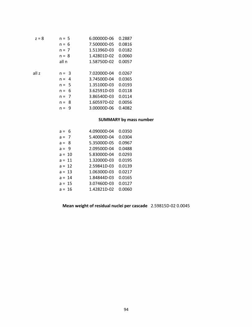
94
z = 8 n = 5 6.00000D-06 0.2887 n = 6 7.50000D-05 0.0816 n = 7 1.51396D-03 0.0182 n = 8 1.42801D-02 0.0060 all n 1.58750D-02 0.0057 all z n = 3 7.02000D-04 0.0267 n = 4 3.74500D-04 0.0365 n = 5 1.35100D-03 0.0193 n = 6 3.62591D-03 0.0118 n = 7 3.86540D-03 0.0114 n = 8 1.60597D-02 0.0056 n = 9 3.00000D-06 0.4082
SUMMARY by mass number
a = 6 4.09000D-04 0.0350 a = 7 5.40000D-04 0.0304 a = 8 5.35000D-05 0.0967 a = 9 2.09500D-04 0.0488 a = 10 5.83000D-04 0.0293 a = 11 1.32000D-03 0.0195 a = 12 2.59841D-03 0.0139 a = 13 1.06300D-03 0.0217 a = 14 1.84844D-03 0.0165 a = 15 3.07460D-03 0.0127 a = 16 1.42821D-02 0.0060
Mean weight of residual nuclei per cascade 2.59815D-02 0.0045

95
Figure C.2 – Final BLIP target test arrangement with vacuum section

96
Figure C.3 – Vacuum capsule drawing
Figure C.4 – MARS power density results for final BLIP set up (Figure C.2)
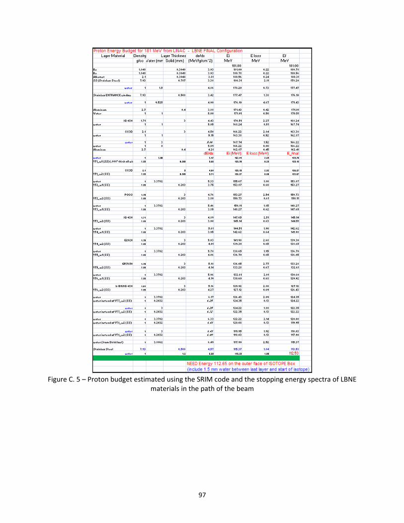
97
Figure C. 5 – Proton budget estimated using the SRIM code and the stopping energy spectra of LBNE
materials in the path of the beam

98
C.3: LBNE Target Experiment VACUUM Degrader FAILURE On May 17, 2010, while the LBNE experiment was running, increased background radiation levels were recorded at the accelerator complex and around BLIP indicating that conditions similar to those that have caused the “pause” of the experiment were present. In addition, there has been a significant reduction in isotope production from the downstream targets especially in the last of the array of targets (Gallium) which has a narrow cross section peak and also responsible for stopping the proton beam entirely. In an effort to identify the “experimental set-up change” the LBNE targets were examined and in particular the state of the degrader. Visual examination through the lead glass in the BLIP hot cell showed serious deformation and charred spot on the degrader window. At first, it was difficult to determine whether there was total breach of vacuum. In a quick turnaround, the vacuum degrader was replaced with the spare degrader of almost the same dimensions and the LBNE experiment was up running. Post-examination of the degrader revealed that not only was there a depression due to excessive heating/localized melting, but also that the vacuum was breached (Figure C.6). The spot in the middle of the burned area is significantly depressed and has developed a hole allowing water to get in. This implies that water filled the volume which in turn explains the increase in short-lived isotopes detected. The added water column to the beam path may have degraded the beam energy enough for the Gallium target to completely miss the optimum cross section. Important to also note is that the window that failed is the thinner of the two (one would have expected the thicker one to me more prone to failure because of more thermal energy deposited in it). A number of unanswered questions still linger because of the type of failure observed. In particular, the fact that while the beam was centered on one of the windows (Figure C.7), it appeared to be off-centered on the other. It is impossible to know whether it was the upstream or the downstream window that failed. The sure thing is that the failed one is the thinner of the two and it is the one welded under vacuum at the end. Important to note is that the beam spot in the “good” window indicates a very tight beam. That could explain why the temperature of the window exceeded the melting point (assisted by closure of the cooling path and heat removal from that face). Efforts are under way to get another estimate of the energy deposition and the thermal/mechanical analysis of the failed window (Figure C.8). NOTE: It is possible that the water gap on the FAILED side of the Vacuum degrader was much larger leading to much lower heat transfer film coefficients. That led to higher temperatures in the stainless steel window (An LS-DYNA sensitivity study on the window with vacuum inside may indicate the maximum temperature anticipated). For higher temperatures over the beam spot, the “scorched” area enlarges. On the other side the scorched area is representative of the beam profile.

99
Figure C.6 - “Breached” vacuum degrader window.
Figure C.7 - Vacuum Degrader Window showing no signs of “breach”.

100
Figure C.8 – Failure analysis of vacuum degrader window

101
REFERENCES Barabash, V., Akiba M., Bonai J., Federici, G., Matera, R., Nakamura, K., Pacher, D., Rodig, M.,
Vieder, G., & Wu, H. (1998). Carbon fibre composites application in ITER plasma facing components. Journal of Nuclear Materials, Vol. 258-263, P, pp. 149-159.
Bonal, J-P., Kohyama K., van der Laan J & Snead L. (2009). Graphite, Ceramics and Ceramic Composites for High-Temperature Nuclear Power Systems. MRS Bulletin, Vol. 34, pp. 28-34.
Brossa, F., Franconi E. & Schiller P. (1992). Development of graphite/metals bondings for fusion reactors applications. Journal of Nuclear Materials, Vol. 191-194, pp. 469-472.
Burchell, T. (1994). Irradiation-induced structure and property changes in tokamak plasma-facing, carbon-carbon composites. Proceedings of the 39th International Symposium of the Society for the Advancement of Material and Process Engineering and Exhibition, Anaheim, CA, April 1994.
Burchell, T. (1996). Radiation Damage in Carbon-Carbon Composites: Structure and Property Effects. Physica Scripta, Vol. T64, pp. 17-25.
Burchell, T., Eatherly, P., Robbins, M. & Strizak P. (1992). The effect of neutron irradiation on the structure and properties of carbon-carbon composite materials. Journal of Nuclear Materials, Vol. 191-194 Part 1, pp. 295-299.
Kelly B. T., The Behavior of Graphite Under Neutron Irradiation, J. Vac. Sci. Technol. A4, pp. 1171-1178, 1986.
Maruyama, N. & Harayama M. (1992). Neutron irradiation effect of thermal conductivity and dimensional change of graphite materials. Journal of Nuclear Materials, Vol. 195, pp. 44-50.
Hurh P. et al, 4th High Power Target Proccedings. Ryazanov A. I. Final Technical Report: The Effect of High-energy Proton Beams on LHC Collimator
Materials, 2008. Schweitzer D. G., Activation Energy for Annealing Single Interstitials in Neutron-Irradiated Graphite
and the Absolute Rate of Formation of Displaced Atoms, Physical Review, Vol. 128, No. 2, 1962.
Shibata T. et al, Oxidation Damage Evaluation by Non-Destructive Method for Graphite Components in High Temperature Gas-Cooled Reactor, Journal of Solid Mechanics and Materials Engineering, Vol. 2, No.1, pp. 166-175, 2008.
Simos, N., Kirk, H.G., Thieberger, P., Ludewig, H., O Conor, J., Mausner, L. Trung P-T., McDonald, K., Yoshimura, K. & Bennett, R. (2008). Irradiation damage studies of high power accelerator materials. Journal of Nuclear Materials, Vol. 377, Part 1, pp. 41-51.
Snead, L. (2004). Ceramic structural composites. The most advanced structural material. Presentation at the International School on Fusion Reactor Technology, Erice, Italy, July 26 – August. 1 1
MARS-15 Monte Carlo Code MCNPX SRIM LS-DYNA TrueGrid ANSYS