longwall shearer performance using water-jet-assisted … · son for using the longwall mining...
TRANSCRIPT
iRIi 90461
PLEASE DO NOT REMOVE FROM LIBRARY
Bureau of Mines Report of Investigations/1986
Longwall Shearer Performance Using Water-Jet-Assisted Cutting
By P. D. Kovscek, c. D. Taylor, H. Handewith, and E. D. Thimons
UNITED STATES DEPARTMENT OF THE INTERIOR
Report of Investigations 9046
Longwall Shearer Performance Using Water-Jet-Assisted Cutting
By, P. D. Kovscek. C. D. Taylor. H. Handewith. and E. D. Thimons
UNITED STATES DEPARTMENT OF THE INTERIOR Donald Paul Hodel. Secretary
BUREAU OF MINES Robert C. Horton. Director
Library of Congress Cataloging in Publication Data:
Kovscek, Paul D Longwall shearer performance using water-jet-assisted cutting.
(Report of Investigations/Bureau of Mines; 9046)
Bibliography: p. 1l-12.
Supl. of Docs. no.: I 28.23:9046.
1. Longwall mining- Equipment and supplies-Testing. 2. Jet cutting. 3. Coal -mining machinery - Testing. l. Kovscek, P. D. (Paul D.). II. Series: Report of Investigations (l!nited States. Bureau of Mines); 9046.
TN23.U43 [TN292] 622 s [662'.334] 86·600240
CONTENTS
Abstract."" .......................................... " .. " ...... " .... "" .... " .. " .. " .......................... " .. """ .... ,,................ 1 Introduction ... " .. " .............................. " .. "" .. " .... " "" ...................... " .. " " ................ " ................ " .. " .. 2 Acknowledgments .... " " .... " ...... ................ " .... " .. " .... " .. .. "" .. " .. " .... .... .. ...... .............. ...... .. .. .. .. .... " .. .... ") 2 Description of longwall test facility...... .. .......... . ..... .. .. . .... .. ..... .. 3
Test block ............. o •••••••••••••••••••••••••• c •••••••• "t·................ 3 Shearer .. " .... " " " .... " " " .. " " " " .. " " ........................ " " .......... " .... " ................ " .. " .. " " " " ...... " .. .. .. .. .. .. .. 3 Water spray system ........... " ..... """ .. , .. "" .. """ .......... "".................................................. .. .......... 3
Sampling procedure .................. " .. " ........ " .................... " ........ ........ .. .. .... .. " ............ " .. .. .... .. .............. 5 Instrumentation and parameters moni tored..................................... 5 Data collection system........ . ....... . ..... .. ........ . ... . .... . ... . . ........ 6
Re suI t s ...................................•.•.......... 1;1 • • • • • • • • • • • • • • • • • • • • • • • 8 Discussion. . . .. . . . . . . . . .. . • .. ... .. .. .. . . . . •••• . • • . . .. •. . . . ... . . . . . . .. ..... . . . • . 9
Effect on shearer motor energy............................................... 9 Positive impacts on water-jet-assisted cutting............................... 10 Potential benefit of improved bit wear on machine performance................ 11
Conclusions. • • • • • • • • . •• • • • • • • • • ••• • • • • •• • • • •• • •• •• • •• • • ••• •••• • •••• •• • •••• • • •• • 11 References .................................... "................................ 11 Appendix A.--Properties of coalcrete test face................................. 13 Appendix B.--Factors affecting shearer cutting efficiency...................... 14
1. 2. 3. 4. 5. 6. 7. 8. 9.
10. B-I. B-2 c
1. 2. 3. 4.
A-I.
ILLUSTRATIONS
Longwall shearer ..............••.....................••.................. Bit lacing pattern and water-conducting segments on longwall drum •••••••• Bit assembly and spray nozzle •••••••••••••••••••••••••••••••••••••••••••• Test locations on coalcrete block •••••••••••••••••••••••••••••••••••••••• Longwall shearer instrumentation block diagram ••••••••••••••••••••••••••• Dust sampling locations •••••••••••••••••••••••••••••••••••••••••••••••••• Ducting for dust sampling box •••••••••••••••••••••••••••••••••••••••••••• Coalcrete chip distributions for jet pressures of 1,000 to 6,000 psi ••••• Median particle size versus water pressure ••••••••••••••••••••••••••••••• Energy per ton versus jet pressure ••••••••••••••••• • •••• •• ••••••••••• • ••• Shearer motor energy per ton versus depth to cut ••••••••••••••••• • ••••••• Shearer motor energy utilized per ton versus depth of cut ••••••••••••••••
TABLES
Design specifications for shearer and cutting drum ••••••••••••••••••••••• Operating parameters for shearer tests ••••••••••••••••••••••••••••••••••• Energy per ton of material cut •••••••••.••••••••••••••••••••••••••••••••• Dust sampling results, compared with conventional (190-psi) spray operation ................................................•..............
Compressive strength of coalcrete ••••••••••••••••••••••••••••••••••••••••
3 4 4 5 6 7 7 8 9
10 14 15
4 6 9
9 13

UNIT OF MEASURE ABBREVIATIONS USED IN THIS REPORT
ft foot mm millimeter
ft/min foot per minute pct percent
gal/min gallon per minute ppv part per volume
hp horsepower psi pound per square inch
in inch r/min revolution per minute
kW kilowatt s second
kW"h/st kilowatt-hour per short st short ton ton (2,000 lbf)
V ac voltage, alternating lb pound current
lbf/ft3 pound (force) per V dc voltage, direct cubic foot current
min minute
LONGWALL SHEARER PERFORMANCE USING WATER·JET·ASSISTED CUTTING
By P. D. Kovscek,l C. D. Taylor,2 H. Handewith,3 and E. D. Thimons4
ABSTRACT
The Bureau of Mines equipped a longwall shearer with a waterjet-assisted mechanical cutting system to determine the effect of the high-pressure sprays on machine performance, airborne dust levels generated, and size of particles formed. Testing was conducted on a simulated coal block (coalcrete) while cutting at a water pressure of 190 psi and at water-jet-assisted pressures ranging from 1,000 to 6,000 psi. The shearer motor energy used by the shearer while cutting coalcrete was determined for each cutting condition. Results indicate that the motor energy required by the shearer for each ton of material cut did not vary significantly as the water pressure was increased. Results of dust measurements recorded near the cutting drum indicate that at water pressures above 3,000 psi, dust reductions up to 85 pct were achieved compared with cutting with conventional sprays. Analysis of the particle size distribution during cutting showed that increasing the water pressure resulted in increased median particle size. In light of these results, various mechanisms for water-jet-assisted cutting are discussed.
1pro ject engineer, Boeing Services International, Pittsburgh, PA. 2Industrial hygienist, Pittsburgh Research Center, Bureau of Mines, Pittsburgh, PA. 3Marke ting manager, AD MAC Inc., Kent, WA. 4supervisory physical scientist, Pittsburgh Research Center.

2
INTRODUCTION
Improved productivity is a primary reason for using the longwall mining method. Average U.s. longwall production is 700 to 1,200 st/shift compared with 300 to 400 st/shift for room and pillar mining.
Since 1977 the number of u.s " longwall mining sections using double-ended ranging-arm shearers has increased from 37 to 89. To achieve these production levels, the average horsepower supplied to a longwall shearer has increased from 333 hp in 1977 to 403 hp in 1984 (1-2).5
In this study shearer motor en;rgy is defined as the kilowatt-hours of energy used by the shearer to cut 1 st of coalcrete. The shearer motor energy is used as a measure of shearer cutting efficiency. Therefore, lowering the shearer motor energy will result in a more efficient cutting operation. One objective of this study was to determine, by measuring shearer motor energy, if the cutting efficiency of the machine was improved when using water-jet-assisted cutting. The effect of the high-pressure jets on dust production and particle size distribution was also evaluated.
Water-jet-assisted cutting, which the Bureau of Mines defines as the use of moderately high pressure (3,000- to 10,000· ·psi) solid streams of water (re··" ferred to as water jets) directed near the cutting bit tip, has been proposed as a way to improve cutting efficiency and reliability of mining machines that use drag bits. The energy supplied by
the water jets can be measured, and the effect of the fluid energy on cutting efficiency can be determined by observing changes in shearer motor energy . Waterjet energy can be calculated, in terms of kilowatt hours, for the amount of fluid energy supplied per ton of coalcrete cut. The relative amounts of energy supplied by the shearer and water sprays can then be compared.
Several mechanisms have been suggested to explain why water-jet-assisted cutting may improve cutting efficiency (3-6). These include precleaning of the-bit path, jet lubrication of the tool and/ or rock interface, and propagation of mechanically induced rock cracks. Laboratory test results have shown improved cutting when a high-pressure spray is used with a mechanical bit. However, these tests were performed at cutting speeds much slower «100 ft/min) and at depths of cut more shallow «0.5 in) than would be used normally when mining.
Under normal ID1n~ng conditions, there are few opportunities to compare quantitatively the cutting efficiency of a mining machine operating with and without water jets. Qualitatively it has been shown that a roadheader operating with water-jet assist was able to mine hard rock that could not be cut without highpressure water (~). Equipping a fullsize longwall shearer with high-pressure water provides the opportunity to quantify machine performance when using waterjet-assisted cutting.
ACKNOWLEDGMENTS
The authors acknowledge the assistance provided by the following Boeing Services personnel, Pittsburgh, PA: J. Leslie Thompson and Michael Leigh, senior
5Underlined numbers in parentheses refer to items in the list of references preceding the appendixes.
project engineers; Jon A. Hummer, engineer; Allen Constantine, A. Wayne Himler, and Raymond Vereneck, engineering technicians; John Lucas, mechanical technician; William Obricki, systems analyst; Paul D. Adkins, programmer; and Michael Henderson, deputy program manager.
3
DESCRIPTION OF LONGWALL TEST FACILITY
TEST BLOCK
To evaluate the practicality of a moderate-pressure water-jet assisted mining system in a simulated underground en···· vironment, a 60-ft-long by 6-ft-high simulated coal (coalcrete) block, composed of coal, fly ash, and concrete, was used to simulate a longwall coal face. Owing to its higher silica content, coalcrete is more abrasive than coal. However, when conventional drag bits are used, its cutting properties are similar. A more detailed description of the coalcrete block is given in appendix A.
6Reference to specific products does not imply endorsement by the Bureau of Mines.
SHEARER
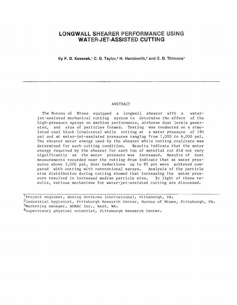
The shearer used to cut the coalcrete was a Joy 1-LS1 6 double-drum machine (fig. 1). For all tests cutting was from right to left. Only the left-hand drum was equipped for water-jet-assisted cutting, and only it was used for cutting. The right-hand drum was positioned so that it moved within the cut made by the left-hand drum. A longwall face conveyor panline, adjacent to the coalcrete block~ provided continuous removal of the cut material, as well as functioning as a support along which the shearer moved. The relevant design specifications of the Joy shearer and cutter drum are given in table 1.
FIGURE 1-Longwall shearer.
4
TABLE 1 . - Design specifications for shearer and cutting drum
Shearer (Joy 1-'LSl), with double drum and extended boom:
Haulage .•..••••••••••
Haulage motor •••••••• Cutterhead motor •••••
Cutting drum: Number of starts ••••• Total wrap angle ••••• Vane web width ••••••• Drum bit tip diam •••• Drum speed ••••••••••• Bit tip velocity ••••• Lateral bit spacing ••
Cutting bits (radial attack).
Chainless (rackatrack). 35-hp V dc. 100-hp V ac .
2 437 0
28 in. 54 in. 47 r/min. 650 ft/min. 1-1/2 to 2 in;
1 bit per line. 32
Jet nozzle' diam ••••. 0.6 mm. 'Modified 3/8-in socket-head cap screw,
316 stainless steel, with 13 0 taper.
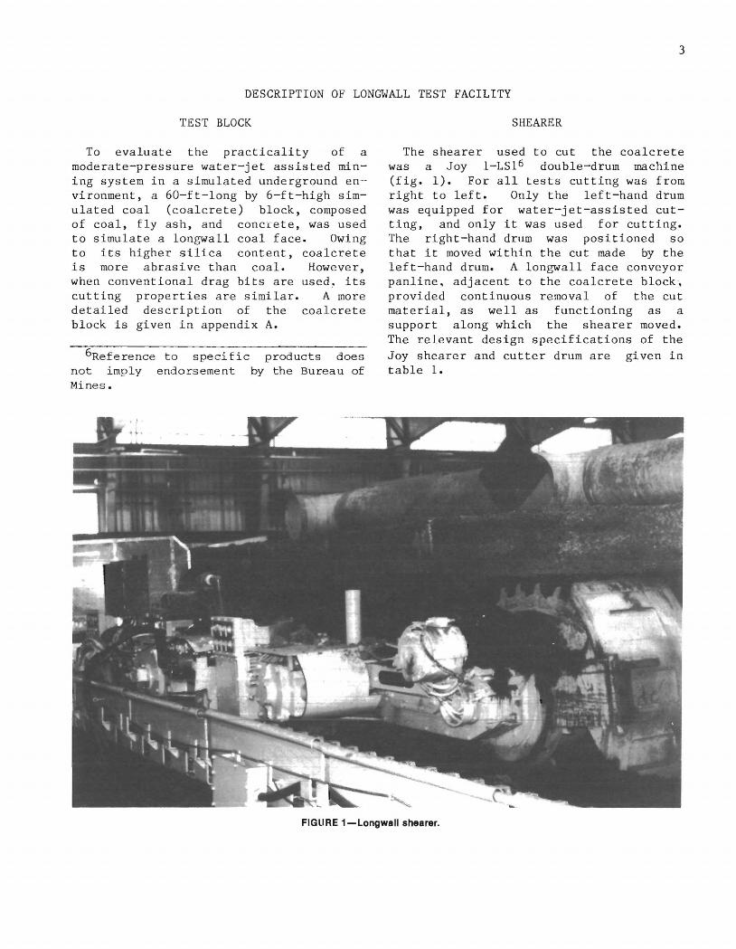
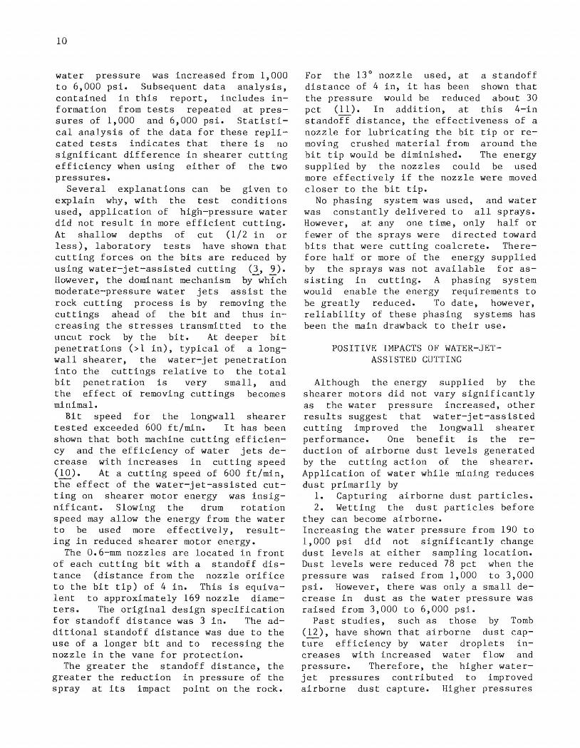
Figure 2 shows the cutter head "unwrapped" with the 32 bits numbered. The bits were numbered starting with the face ring and continuing along each of the two vanes. Water was supplied to the drum through an Aqua-Dyne rotary seal, which is a small-diameter, high-pressure rotary seal located in the drum hub. The high-pressure water was supplied by a 200-hp (149-kW) Aqua-Dyne triplex pump that has a capacity of 50 gal/min at an operating pressure of 6,000 psi. The cutter drum was designed to have six equal water-conducting segments. Each segment received high-pressure water at the hub and directed it to all bits contained in those segments designated A
to F on figure 2.
WATER SPRAY SYSTEM
The water-jet cutting drum has jet nozzles for each of the 32 bits. For the high- and low-pressure spray tests, nozzles having 0.6- and 1.78-mm orifices, respectively, were located in front of each bit. For protection, the nozzles each recessed in the drum vanes, resulting in a standoff distance of 4 in (fig. 3).
Cl Q)
"C
Z o
~ (.)
o ~
Or---r---'---.---~--.---~ A .32 1
40 -t-------------19-~-~-{ B m 4 I:: +------~;-?!---------~~
160 -\243L-----------9-
B1 200 ~FL-----------2L--/l~
::: -1-------;9 -~~ ~----iff F /5
320! 30 16
t 31 17 360~A~~--~--~--~--~--~
30 25 20 15 10 5 0 WIDTH, in
FIGU RE 2.-Blt lacing pattern (Nos. 1·32) and water· con.du.~t.lng_ugment8 (A·F) 011 10ngYf!lIL~rum.
I 4"
Enlarged view of nozzle
FIGURE 3.-Blt assembly and spray nozzle.
The water-jet nozzles were made from stainless steel, 3/8-in-diam hexagonal socket-head screws , which were machined
down to an internal Leach and Walker configuration (flg. 3). Brass nozzles of
5
similar design (13 0 taper) were used to simulate conventional water sprays.
SAMPLING PROCEDURE
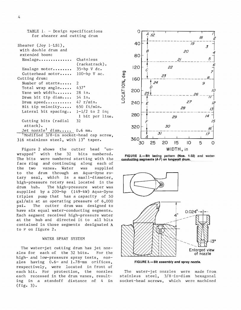
As shown in figure 4, three passes were made on the simulated coal block. Each pass began with a sump cut that allowed the face to be squared prior to the first test cut. The first pass consisted of six test segments, each approximately 6 ft long. While cutting each segment a constant water-jet pressure, between 1,000 and 6,000 psi, was maintained. During the second pass one 15-ft and one 20-ft section of coalcrete were cut using 6,000-psi water jets. A third 10-ft segment was cut at a pressure of 1,000 psi. To simulate cutting with conventional water sprays, 35 ft of the third pass was cut using a water pressure of 190 psi. To simulate dry cutting, 15 ft of the third pass was cut without water.
INSTRUMENTATION AND PARAMETERS MONITORED
Cutting efficiency for these tests was based on the shearer motor energy. Water-jet energy supplied by the water sprays was also determined. Power supplied by the shearer and tne sprays was monitored in order to calculate shearer and fluid energy. Machine power was determined by summing the power contributions of the left-hand cutter and haulage motors. Mechanical shaft power of the cutter drive motor was estimated by measuring electrical power entering the motor, less motor losses due to windage, coil resistance, and core inefficiencies. Power required for electric motors driving the
I 60 ft
Dry cut Sump 190 psi, 35ft cut 15 It 10ft
No I 1,000 6,000 pSI
I 6,000 psi . Sump
data pSI cut 10 ft 20 ft 15 It 10ft
No data 11,000 12,000 13,O()0 14,000 15,000 16,0()0 Sump' ~SI ~Sl ~Sl pSI PSI pSI cut
It It ft i 6 ft 6 ft 6 ft .10 It
" ---Cutting direction
FIGURE 4.- Test locations on coalcrete block.
I 3d
pass
2d pass
1st poss
hydraulic pump and right-hand cutter was not included because the power consumption for these motors was not directly related to the coal cutting effort of the water-jet drum.
Because the drive train is direct-gear driven with a low-slip motor, the drum speed was relatively constant (appro~. 47 r/min) for all load conditions. A mag~ netic pickup was mounted to measure gear-tooth passing frequency, which was then converted to a 0- to 10-V dc analog output. The motor output shaft velocity was measured and converted to cutter drum rotational velocity.
A pulse rate indicator was used to monitor the haulage motor output shaft velocity. The output of the indicator was converted to analog voltage, which was proportional to the haulage speed.
Power supplied by the sprays was calculated based on water pressure and flow rate. A 0- to 10,OOO-psi pressure transducer was installed in the high-pressure water feed line adjacent to the cutter-' head to determine water pressure. A turbine-type flow meter was used for recording water flow rate. A block diagram of the data instrumentation system is shown in figure 5.
The power expended by the water sprays was proportional to the water pressure and flow rate. If water flow rate (V) is given in gallons per minute and water pressure (p) in pounds per square inch, the fluid horsepower can be calculated by the following equation:
Fluid hp = P x V/1714.
Jet power in kilowatts is then calculated by
Jet power(kW) = (Fluid hp)(0.7457).
Fluid power calculations shown in table 2 were bas~d on the total water flow provided by all 32 operating sprays.

6
Wotts transducer
440 V - 3 phose 440 V - 3 phose
Water jets
Haulage rack
J J J I I Lwoter pressure Haulage motor Cutter motor Haulage rate -Water flow
power power Cutter drum speed
FIGURE 5.-Longwall shearer Instrumentation block diagram.
The amount of material removed, in tons, was determined by measuring the volume of material cut and assuming a specific gravity for coalcrete of 106 lbf/ft 3 • Only that volume of each test cut during which steady-state conditions were maintained was used in calculating the machine and fluid energies. Sheare r and water spray operating parameters, as well as tonnage cut, are given in table 2.
Dorr-Oliver 10-mm nylon cyclones were used at the sampling locations indicated on figure 6 to sample airborne respirable dust. Two "exterior" cyclones were hung about 72 in from the cutting drum at approximately the same height as the top of the cut. Two "interior " cyclones were placed inside a wooden dust-sampling box on top of the shearer. Air was drawn ~nto the sampling box through 2-1/2-indiam PVC plastic tubing. The tubing inlet was located approximately 24 in from the bottom of the cutting drum (fig. 7). Interior and exterior cyclones were attached by Tygon plastic tubing to RAM-1 dust monitors which continuously monitored dust levels.
Cuttings of the coalcrete were sampled from the center of each test area. Approximately 4 lb of cuttings was collected for each test pressure. Two representative portions of each sample were taken and dry-sieved. Using 8-in-diam sieves, particles were separated according to U.S. standard sieve sizes (1 in to 0.0196 in). For each sieve size, the weights collected from the two sample portion.s were averaged.
DATA COLLECTION SYSTEM
Parameters required for monitoring machine and fluid energy were recorded on
TABLE 2. - Operating parameters for shearer tests
Spra pressure, psi Nozzle Test Weight Power consumption, kW Test Design Actual flow, time,
, cut,2 Total Cutter Haulage Machine jet gal/min min st fluid3
1 6,000 5,750 1. 22 1. 35 2.84 97.79 98.66 2.92 101.58 2 6,000 6,173 1. 32 2.30 6.78 113.53 109.65 3.11 112.69 3 6,000 5,996 1. 31 3.41 10.15 109.21 121.64 3.10 124.76 4 5,000 5,023 1.16 1.11 2.59 81. 20 101.16 3.15 104.31 5 4,000 3,933 1.01 .85 2.29 55.05 110.00 3.52 113.52 6 3,000 2,905 .81 1.07 2.68 32.85 110.75 3.11 113.86 7 2,000 2,018 .68 1.16 2.90 19.22 108.04 2.90 110.94 8 1,000 1,098 .50 1.23 3.16 7.62 114.77 2.82 117.59 9 1,000 1,127 .47 1. 55 4.61 7.36 118.46 3.36 121.82
10 190 190 .86 5.55 14.90 2.28 121.62 3.56 125.18 11 0 0 .0 2.79 7.24 .0 113.04 3.69 116.73
'Data collected for steady-state conditions. 2Total coalcrete cut during test; based on steady-state conditions. 3Fluid power calculations based on measured water pressure and flow rate for
32 sprays.

Lead drum
KEY R RAM-I dust monitor
Exterior Plastic shield
Plastic tub ing (2.5-in-diam) ~
I=----'----~~
Shearer
FIGURE S.-Dust sampling locations.
FIGURE 7.-Ductlng for dust sampling box.
Dust
Interior cyclones
7
8
an FM magnetic tape recorder as analog signals. Data reduction was implemented through subsequent playback into an analog-to-digital (A/D) converter with an extended memory unit (EMU). A multiconductor linked the acquisition site and computer.
The test data were entered into the EMU at 80 samples per second for pass 1, and at 10 samples per second for passes 2 and 3. The data were sampled during steadystate coalcrete cutting modes to elimi-nate noncutting conditions and cutter stall conditions. The representative data samples were then used to calculate the average of the instrumented parameters for each test.
The analog output from each RAM-I instrument, which monitored dust levels, was recorded by a Soltec strip-chart recorder. For each test, the area under the recorded curve was measured using a compensating polar planimeter.
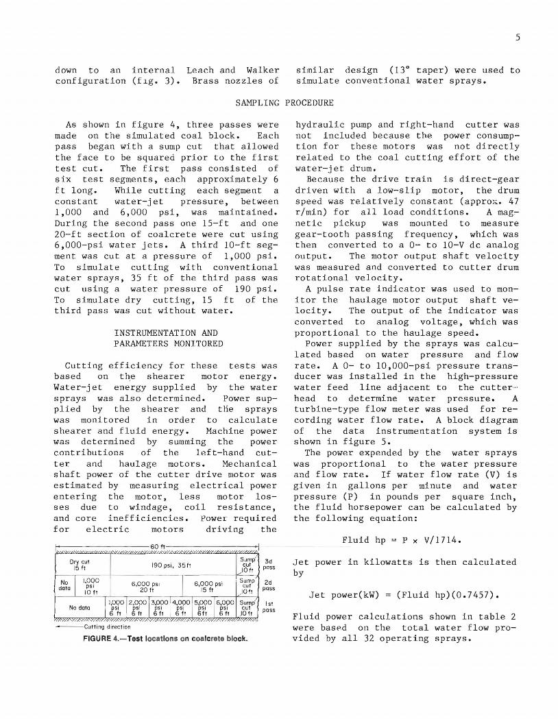
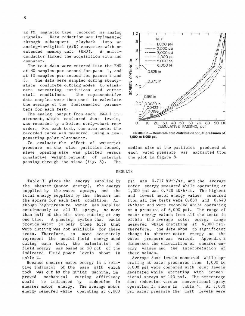
To evaluate the effect of water-jet pressure on the size particles formed, sieve opening size was plotted versus cumulative weight-percent of material passing through the sieve (fig. 8). The
1.0
.9 --1,000 psi
.8 .. _ . - 2,000 psi --- 3,000 psi
.7 ---- 4,000 psi
.£ --- 5,000 psi cD -- 6,000 psi z .6 Z 0.625 in w n.. .5 0
z ,0.375 in w .4 w a:: u (f) .3
.2
.1
o 10 20 30 40 50 60 70 80 90 100 CUMULATIVE PASSING, pet
FIGURE 8.-Coalcrete chip distribution for Jet pressures of 1,000 to 8,000 psi.
median size of the particles produced at each water pressure was extracted from the plot in figure 8.
RESULTS
Table 3 gives the energy supplied by the shearer (motor energy), the energy supplied by the water sprays, and the total energy supplied by the shearer and the sprays for each test condition" Although high-pressure water was supplied continuously to all 32 sprays, no more than half of the bits were cutting at any one time. A phasing system that would provide water to only those bits that were cutting was not available for these tests. Therefore, to more accurately represent the useful fluid energy used during each test, the calculation of fluid energy was based on 50 pct of the indicated fluid power levels shown in table 2.
Because shearer motor energy is a relative indicator of the ease with which rock was cut by the mining machine, improved mechanical cutting efficiency would be indicated by reduction in shearer motor energy_ The average motor energy measured while operating at 6,000
psi was 0.717 kW·h/st, and the average motor energy measured while operating at 1,000 psi was 0.720 kW·h/st. The highest and lowest motor energy values measured from all the tests were 0.860 and 0.640 kW·h/st and were recorded while operating at a pressure of 6,000 psi. The range of motor energy values from all the tests is within the average motor energy range measured while operating at 6,000 psi. Therefore, the data show no significant change in shearer motor energy as the water pressure was varied. Appendix B discusses the calculation of shearer energy values and the interpretation of these values.
Average dust levels measured while operating at water pressures from 1,000 to 6,000 psi were compared with dust levels generated while operating with conventional sprays at 190 psi. The percentage dust reduction versus conventional spray operation is shown in table 4. At 3,000 psi water pressure the dust levels were

TABLE 3. - Energy per ton of material cut
Pressure, Energy, kW·h/st Test psi Total Shearer Water-
jet 1
1 6,000 1. 20 0.81 0.39 2 6,000 .96 .64 .32 3 6,000 1. 0 1 .70 .31 4 5,000 1.04 .75 .29 5 4,000 .88 .71 .17 6 3,000 .87 .76 .ll 7 2,000 .81 .74 .07 8 1,000 .79 .76 .03 9 1,000 .70 .68 .02
10 190 .79 .78 .01 11 0 .71 .71 .00
lBased on 50 pct of total water-jet power.
79.2 pct less than when operating with conventional sprays. Raising the pressure further from 3,000 to 6,000 psi resulted in only small additional dust reductions.
TABLE 4. - Dust sampling results, compared with conventional (190-psi) spray operation
9
Pressure, psi Dust reduction, pct
6,000............... 80.4 5,000............... 84.8 4,000.............. . 80.4 3,000............... 79.2 2,000............... 63.9 1,000............... 4.2 190 . • • . • . . . • • • . • . . . • 0 Dry................. - 31.4
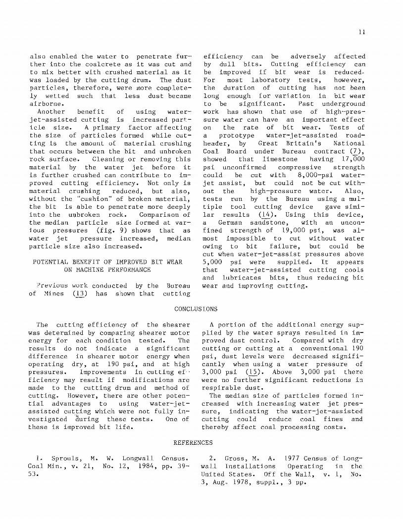
Figure 9 plots median particle size versus water pressure. In general, median particle size tended to increase with increasing water pressure. This implies that water"jet-assisted cutting could reduce coal fines, which cause problems in cleaning plants and are often unwanted by coal buyers.
DISCUSSION
EFFECT ON SHEARER MOTOR ENERGY
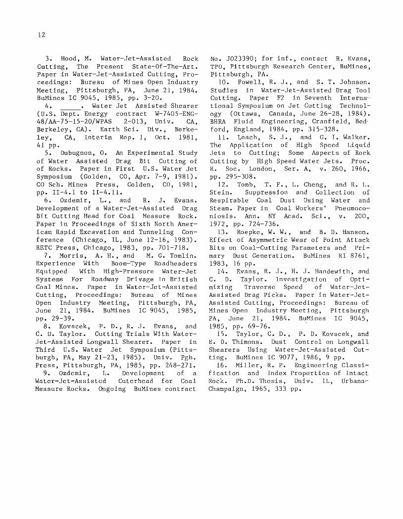
For this study, shearer motor energy was used to indicate shearer cutting efficiency. Shearer and total energies, given in table 3, are plotted in figure 10, which shows that the shearer motor energy remained relatively constant for all conditions tested. The data also show that at the higher water pressures a significant percentage of the total energy supplied was provided by the water sprays, even if it is assumed that a water phasing system supplies water to only half of the water sprays. At 190 psi the water applied accounts for less
0 .30 . <:: W o N
~UJ -w o-.J Wu ::;:-
f-0:: [f:
.10 0 2 4 6
WATER PRESSURE, 103 psi
FIGURE g.-Median particle size versus water pressure.
than ~ pct of the total energy supplied during cutting. At 6,000 psi almost 33 pct of the total energy supplied during cutting was provided by the water sprays.
Preliminary results from this longwall shearer work were presented at the Third U.S. Water-Jet Conference (~). At the conference it was stated that, based on data from only the first pass, shearer cutting efficiency was improved when the
~"
a z o f-a:: w a...
1.6
1.2
. 8
~ .4 a:: w z w
• •
~
• ~ A • • • • • KEY
• Shearer motor energy A Total energy(shearer motor and
water- jet fluid energy)
~
~~
• • •
o~--~--~----~---L----L----L--~
2 3 4 5 6 7 JET PRESSURE, 103 psi
FIGURE 10.-Energy per ton versus Jet pressure.
10
water pressure was increased from 1,000 to 6,000 psi. Subsequent data analysis, contained in this report, includes information from tests repeated at pressures of 1,000 and 6,000 psi. Statistical analysis of the data for these replicated tests indicates that there is no significant difference in shearer cutting efficiency when using either of the two pressures.
Several explanations can be given to explain why, with the test conditions used, application of high-pressure water did not result in more efficient cutting. At shallow depths of cut (1/2 in or less), laboratory tests have shown that cutting forces on the bits are reduced by using water-jet-assisted cutting (3, 9). However, the dominant mechanism by-which moderate-pressure water jets assist the rock cutting process is by removing the cuttings ahead of the bit and thus increasing the stresses transmitted to the uncut rock by the bit. At deeper bit penetrations (>1 in), typical of a longwall shearer, the water-jet penetration into the cuttings relative to the total bit penetration is very small, and the effect of removing cuttings becomes minimal.
Bit speed for the longwall shearer tested exceeded 600 ft/min. It has been shown that both machine cutting efficiency and the efficiency of water jets decrease with increases in cutting speed (!Q). At a cutting speed of 600 ft/min, the effect of the water-jet-assisted cutting on shearer motor energy was insignificant. Slowing the drum rotation speed may allow the energy from the water to be used more effectively, resulting in reduced shearer motor energy.
The 0.6-mm nozzles are located in front of each cutting bit with a standoff distance (distance from the nozzle orifice to the bit tip) of 4 in. This is equivalent to approximately 169 nozzle diameters. The original design specification for standoff distance was 3 in. The additional standoff distance was due to the use of a longer bit and to recessing the nozzle in the vane for protection.
The greater the standoff distance, the greater the reduction in pressure of the spray at its impact point on the rock.
For the 13° nozzle used , at a standoff distance of 4 in, it has been shown that the pressure would be reduced about 30 pct (11). In addition, at this 4-in standoff distance, the effectiveness of a nozzle for lubricating the bit tip or removing crushed material from around the bit tip would be diminished. The energy supplied by the nozzles could be used more effectively if the nozzle were moved closer to the bit tip.
No phasing system was used, and water was constantly delivered to all sprays. However, at anyone time, only half or fewer of the sprays were directed toward bits that were cutting coalcrete. Therefore half or more of the energy supplied by the sprays was not available for assisting in cutting. A phasing system would enable the energy requirements to be greatly reduced. To date, however, reliability of these phasing systems has been the main drawback to their use.
POSITIVE IMPACTS OF WATER-JETASSISTED CUTTING
Although the energy supplied by the shearer motors did not vary significantly as the water pressure increased, other results suggest that water-jet-assisted cutting improved the longwall shearer performance. One benefit is the reduction of airborne dust levels generated by the cutting action of the shearer. Application of water while mining reduces dust primarily by
1. Capturing airborne dust particles. 2. Wetting the dust particles before
they can become airborne. Increasing the water pressure from 190 to 1,000 psi did not significantly change dust levels at either sampling location. Dust levels were reduced 78 pct when the pressure was raised from 1,000 to 3,000 psi. However, there was only a small decrease in dust as the water pressure was raised from 3,000 to 6,000 psi.
Past studies, such as those by Tomb (12), have shown that airborne dust capture efficiency by water droplets increases with increased water flow and pressure. Therefore, the higher waterjet pressures contributed to improved airborne dust capture. Higher pressures
also enabled the water to penetrate fur ther into the coalcrete as it was cut and to mix better with crushed material as it was loaded by the cutting drum. The dust particles, therefore, were more completely we tted such that less dust became airborne.
Another benefit of using waterjet-assisted cutting is increased particle size. A primary factor affecting the size of particles formed while cutting is the amount of material crushing that occurs between the bit and unbroken rock surface. Cleaning or removing this material by the water jet before it is further crushed can contribute to improved cutting efficiency. Not only is material crushing reduced, but also, without the "cushion" of broken material, the bit is able to penetrate more deeply into the unbroken rock. Comparison of the median particle size formed at various pressures (fig. 9) shows that as water jet pressure increased, median particle size also increased.
POTENTIAL BENEFIT OF IMPROVED BIT WEAR ON MACHINE PERFORMANCE
Previous work conducted by the of Mines (ll) has shown that
Bureau cutting
11
efficiency can be adversely affected by dull bits. Cutting efficiency can be improved if bit wear is reducedFor most laboratory tests, however, the duration of cutting has not been long enough for variation in bit wear to be significant. Past underground work has shown that use of high-pressure water can have an important effect on the rate of bit wear. Tests of a prototype water-jet-assisted roadheader, by Great Britain's National Coal Board under Bureau contract (7), showed that limestone having 17,000 psi unconfirmed compressive strength could be cut with 8,000-psi waterjet assist, but could not be cut without the high-pressure water. Also, tests run by the Bureau using a multiple tool cutting device gave S~mllar results (14). Using this device, a German sandStone, with an unconfined strength of 19,000 psi, was almost impossible to cut without water owing to bit failure, but could be cut when water-jet-assist pressures above 5,000 psi were supplied. It appears that water-jet-assisted cutting cools and lubricates bits, thus reducing bit wear and improving cutting.
CONCLUSIONS
The cutting efficiency of the shearer was determined by comparing shearer motor energy for each condition tested. The results do not indicate a significant difference in shearer motor energy when operating dry, at 190 psi, and at high pressures. Improvements in cutting ef· ficiency may result if modifications are made to the cutting drum and method of cutting. However, there are other potential advantages to using water-jetassisted cutting which were not fully investigated 'during these tests. One of these is improved bit life.
A portion of the additional energy supplied by the water sprays resulted in improved dust control. Compared with dry cutting or cutting at a conventional 190 psi, dust levels were decreased significantly when using a water pressure of 3,000 psi (!2). Above 3,000 psi there were no further significant reductions in respirable dust.
The median size of particles formed increased with increasing water jet pressure, indicating the water-jet-assisted cutting could reduce coal fines and thereby affect coal processing costs.
REFERENCES
L Sprouls. M. Coal Min., v. 21, 53.
W. Longwall Census. No. 12, 1984, pp. 39-
2. Gross , M. A. 1977 Census of Longwall Installations Operating in the United States. Off the Wall, v. 1, No. 3, Aug" 1978, suppI., 3 pp.
12
3. Hood, M. Water-jet-Assisted Rock Cutting, The Present State-Of-The-Art. Paper in Water-jet-Assisted Cutting, Proceedings: Bureau of Mines Open Industry Meeting, Pittsburgh, PA, June 21, 1984. BuMines IC 9045, 1985, pp. 3-20.
4. Water Jet Assisted Shearer (U.S. Dept. Energy contract W-7405-ENG-48/AA- 75- 15- 20/WPAS 2- 013, Univ. CA, Berkeley, CA). Earth Sci. Div., Berkeley, CA, Interim Rep. 1, Oct. 1981, 41 pp.
5. Dubugnon, O. of Water Assisted of Rocks. Paper in Symposium (Golden,
An Experimental Study Drag Bit Cutting of First U.S. Water Jet
CO, Apr. 7-9, 1981). CO Sch. Mines Press, pp. 11-4.1 to 11-4.11.
Golden, CO, 1981,
6. Ozdemir, L., and R. J. Evans. Development of a Water-jet-Assisted Drag Bit Cutting Head for Coal Measure Rock. Paper in Proceedings of Sixth North American Rapid Excavation and Tunneling Conference (Chicago, IL, June 12-16, 1983). RETC Press, Chicago, 1983, pp. 701-718.
7. Morris, A. H., and M. G. Tomlin. Experience With Boom-Type Roadheaders Equipped With High-Pressure Water-Jet Systems For Roadway Drivage In British Coal Mines. Paper in Water-jet-Assisted Cutting, Proceedings: Bureau of Mines Open Industry Meeting, Pittsburgh, PA, June 21, 1984. BuMines IC 9045, 1985, pp. 29-39.
8. Kovscek, P. D., R. J. Evans, and C. D. Taylor. Cutting Trials With WaterJet-Assisted Longwall Shearer. Paper in Third U.S. Water Jet Symposium (Pittsburgh, PA, May 21-23, 1985). Univ. Pgh. Press, Pittsburgh, PA, 1985, pp. 248-271.
9. Ozdemir, L. Development of a Water-jet-Assisted Cuterhead for Coal Measure Rocks. Ongoing BuMines contract
No. J023390; for inf., contact R. Evans, TPO, Pittsburgh Research Center, BuMines, Pittsburgh, PA.
10. Fowell, R. J., and S. T. Johnson. Studies in Water-jet-Assisted Drag Tool Cutting. Paper F2 in Seventh Intern~
tional Symposium on Jet Cutting Technology (Ottawa, Canada, June 26-28, 1984). BHRA Fluid Engineering, Cranfield, Bedford, England, 1984, pp. 315-328.
11. Leach, S. J., and G. I. Walker. The Application of High Speed Liquid Jets to Cutting; Some Aspects of Rock Cutting by High Speed Water Jets. Proc. R. Soc. London, Ser. A, v. 260, 1966, pp. 295-308.
12. Tomb, T. F., L. Cheng, and R. L. Stein. Suppression and Collection of Respirable Coal Dust Using Water and Steam. Paper in Coal Workers' Pneumoconiosis. Ann. NY Acad. Sci., v. 200, 1972, pp. 724-736.
13. Roepke, W. W., and B. D. Hanson. Effect of Asymmetric Wear of Point Attack Bits on Coal-Cutting Parameters and Primary Dust Generation. BuMines RI 8761, 1983, 16 pp.
14. Evans, R. J., H. J. Handewith, and C. D. Taylor. Investigation of Optimlzlng Traverse Speed of Water-JetAssisted Drag Picks. Paper in Water-JetAssisted Cutting, Proceedings: Bureau of Mines Open Industry Meeting, Pittsburgh PA, June 21, 1984. BuMines IC 9045, 1985, pp. 69-76.
15. Taylor, C. D., P. D. Kovscek, and E. D. Thimons. Dust Control on Longwall Shearers Using Water-jet-Assisted Cutting. BuMines IC 9077, 1986, 9 pp.
16. Miller, R. P. Engineering Classification and Index Properties of Intact Rock. Ph.D. Thesis, Univ. IL, UrbanaChampaign, 1965, 333 pp.

13
APPENDIX A.--PROPERTIES OF COALCRETE TEST FACE
The coalcrete block consists of bituminous coal with a nominal size of 1.5 to 2.0 in. A mixture of 10 ppv (parts per volume) bituminous coal, 8 ppv fly ash, 1 ppv portland cement, and 1.5 ppv water was cast in place. The average bulk density when cured is 106 Ibf/ft 3 • The curing time for the coalcrete block prior to the water-jet·-assisted cutting trials was 15 months.
A Schmidt hammer survey was performed on the coalcrete to determine compressive strength of the material at various locations in the test block. The measurements were taken on consolidated coalcrete, approximately 3 ft from the top of the block, and at the distances shown in table A-I from the right side of the block. The calculation is based on a study by R. P. Miller (16),' where Schmidt hammer hardness and -rock density are used to predict compressive strength.
The coalcrete test block offers an advantage over an underground test by
'Underlined numbers in parentheses refer to items in the list of references preceding this appendix.
providing a full-scale test specimen for the water-jet-assisted cutter drum. The shearer mining operations were more precisely controlled than could be accomplished during an underground test, and the cutting properties of the coalcrete block are sufficiently similar to those of coal to enable a reasonable simulation of a longwall face. However, extending the results of the coalcrete tests to virgin coal may not be reasonable because of differences in density, porosity, fracture toughness, and elasticity.
TABLE A-I. - Compressive strength of coalcrete
Distance from right side of block, ft
5 •••••••••••••••••••••••• 15 ••.•....•••••••.•••.•.•• 25 •••••••••••••••••••••••• 35 •••••••••••••••••••••••• 45 •••••••••••••••••••••••• 55 ••••••••••••••••••••••••
Average .......••......•
Compressive strength, psi
4,913 4,162 3,775 4,642 4,934 5,242 "4,611
±223
14
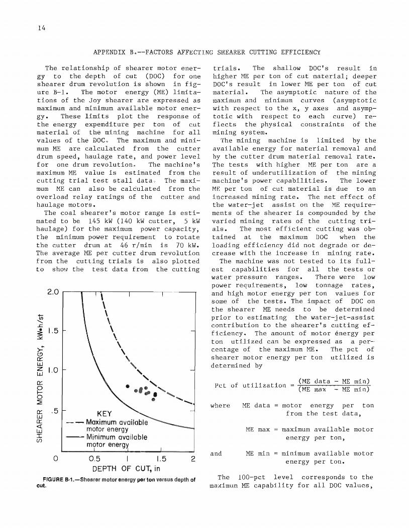
APPENDIX B. --FACTORS AFFECTING SHEARER CUTTING EFFICIENCY
The relationship of shearer motor energy to the depth of cut (DOC) for one shearer drum revolution is shown in figure B-1. The motor energy (ME) limitations of the Joy shearer are expressed as maximum and minimum available motor energy. These limits plot the response of the energy expenditur e pe r ton of cu t material of the mining machine for all values of the DOC .. The maximum and minimum ME are calculated from the cutter drum speed, haulage rate, and power level for one drum revolution. The machine's maximum ME value is estimated from the cutting trial test stall data . The maximum ME can also be cal~ulated from the overload relay ratings of the cutter and haulage motors.
The coal shearer's motor range is estimated to be 145 kW (140 kW cutter, 5 kW haulage) for the maximum power capacity, the minimum power requirement to rotate the cutter drum at 46 rlmin is 70 kW. The average ME per cutter drum revolution from the cutting trials is also plotted to shmv the test data from the cutting
2.0 \ \
+- \ If)
\ ........ ..r= \ • 1.5 ~ \ ~
\ <.9 \ 0::: \ w , z 1.0 w " , 0::: • .' 0 I- .'-. 0 ~ • 0::: .5 KEY w 0::: -- - Maximum available « motor energy w I -- Minimum available (f)
motor energy
0 0.5 1.5 2 DEPTH OF CUT, in
FIGURE B·1.-Shearer motor energy per ton versus depth of cut.
trials. The shallow DOC's result in higher ME per ton of cut material; deeper DOC's result in lower ME per ton of cut material. The asymptotic nature of the maximum and minimum curves (asymptotic with respect to the x, y axes and asymptotic with respect to each curve) reflects the physical c onstraints of the mining system.
The mining machine is limited by the available energy for material removal and by the cutter drum material removal rate. The tests with higher ME per ton are a result of underutilization of the mining machine's power capabilities. The lower ME per ton of cut material is due to an increased mining rate. The net effect of the water-jet assist on the ME requirements of the shearer is compounded by the varied mlnlng rates of the cutting trials. The most efficient cutting was obtained at the maximum DOC when the loading efficiency did not degrade or decrease with the increase in mining rate.
The machine was not tested to its fullest capabilities for all the tests or water pressure ranges. There were low power requirements, low tonnage rates, and high motor energy per ton values for some of the tests. The impact of DOC on the shearer ME needs to be determined prior to estimating the water-jet-assist contribution to the shearer's cutting efficiency. The amount of motor ~nergy per ton utilized can be expressed as a percentage of the maximum ME. The pet of shearer motor energy per ton utilized is determined by
Pct of utilization (ME data - ME min) (ME max - ME min)
where ME data
ME max
and ME min
motor energy per ton from the test data,
maximum available motor energy per ton,
minimum available motor energy per ton.
The 100-pct level corresponds to the maximum ME capability for all DOC values,

and the O-pct level corresponds to the minimum ME value.
The percentage of machine ME utilized increased with increased DOC, as shown in figure B-2. Cutting at a I-in DOC requires 50 pct of the machine ME capabilities, compared with 85 pct when cutting at a 1.4-in DOC. The regression line shows the response of the shearer motor energy for the tange of DOC's recorded for this series of cutting tests.
0.9 KEY
t; - --95-p,ct confidence limits .5/
a. .8 --Curve of best fit I /0 ci' Values, psi X'. w .7 66,000 33.000 5190 //8
3 .4,,' .... t::! .....J 55,OOC 2 2,000 00 ..-/ .2/".6 i= .6 44,OQO / 1,000..-_--- / :::J 5/ >- -- ... --(!) .5 -- .6/ 0:: -- / w z
.4 / w / 0:: / 0
5 .3 / :2
/ /
.2 / 0:: / w 0:: / <! .1 / w / I (/J
0 0.5 1.5 DEPTH OF CUT, in
FIGURE B·2.-Shearer motor energy utilized per ton versus depth of cut.
'" u.s. GOVERNMENT PRINTING OFFICE: 1986-605-D17I40,078
15
Test comparisons at varied DOC's can now be performed using the regression line to establish a predicted response st the different mining rates. The ME values falling below the line would indicate less energy usage at that DOC, whereas the points higher than the regressed line would indicate more energy usage at that DOC.
The 95-pct confidence limits, also shown in figure B-2, reveal that most of the tests are within an expected response and that the application of the water-jet assist had a negligible influence on reducing the motor energy requirements of the shearer. The exceptions are the standard water sprays test and one of the 6,000-psi tests. These test result differences may be due to the varied cut lengths, for which drum loading efficiency may have caused an increase in the shearer motor energy requirements.
The central tendency for the DOC is 1.25±0.25 in (fig. B-l), and the regression line is applicable only for this interval. Figure B-2 shows that at 1.4-in DOC the ME measured while operating at 1,000 psi was within the range of ME levels measured while operating at 6,000 psi. Similarly at 1.25-in DOC, the ME measured while operating dry was within the ME measured while operating at 190 and 4,000 psi.
I NT .-BU.oF MI NES ,PGH .,PA • 28348