lonsdale thermgard design guide · lonsdale thermgard design guide ... bs cp3 chapter v part 2 -...
TRANSCRIPT

Lonsdale ThermGard Design Guide
Introduction This Design Guide has been produced to assist specifiers and designers by illustrating typical installation details for sloped and vertical patent glazing. It is not exhaustive, but it does illustrate good practice for most applications and all details are in accordance with BS5516 for the design and installation of sloped and vertical patent glazing. Users of this guide must exercise all reasonable care to ensure that the details and products of Lonsdale Metal Company Limited are suitable for the intended purpose. If in doubt, ask us. Having decided to specify Lonsdale Patent Glazing, to save you valuable drafting time, CAD drawings of typical installation details are available on disk or from our website : www.roofglazing.co.uk If you require assistance please contact our Technical Department. Lonsdale Metal Company Limited, Millmead Industrial Centre, Mill Mead Road, London. N17 9QU Telephone : 020 8801 4221 Facsimile: 020 8801 1287 Contents
Page
Page Introduction
1
Guide to Selection of Glazing Bars
2
Cleaning and Maintenance
3
Recommended further reading
3
Maximum span between supports
4 & 5
Technical Summary
6
Typical Specification
7
Drawings & CAD Code Index
8
ThermGard CAD drawings
9 to 34
GlazaTherm
35 to 40
Research and Development
41
www.roofglazing.co.uk Page 1
PRINT OUT THIS DESIGN GUIDE FOR REFERENCE IF YOU WISH.
CLICK THE Pages TAB TO SEE THUMBNAILS OF ALL THE PAGES IN THE PUBLICATION. TO PRINT OUT INDIVIDUAL PAGES, CLICK
File, Print THEN CHECK Current page OR SELECT Pages RANGE AND CLICK OK.
TO PRINT DRAWINGS TO THE SCALE INDICATED YOUR PRINT DRIVER MUST BE
CAPABLE OF BEING SET AT 100%. LOOK IN YOUR PRINTER’S Properties FOR SETTINGS. CONTACT OUR TECHNICAL DEPARTMENT
FOR FURTHER ADVICE.
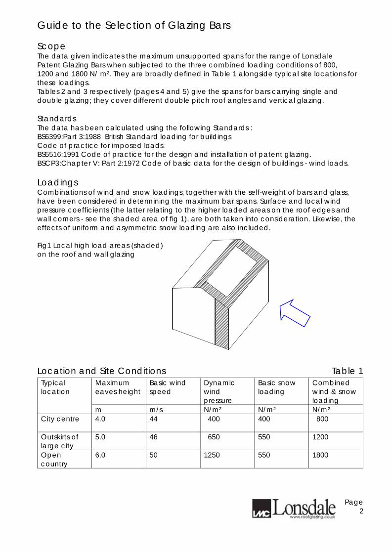
Guide to the Selection of Glazing Bars Scope The data given indicates the maximum unsupported spans for the range of Lonsdale Patent Glazing Bars when subjected to the three combined loading conditions of 800, 1200 and 1800 N/ m². They are broadly defined in Table 1 alongside typical site locations for these loadings. Tables 2 and 3 respectively (pages 4 and 5) give the spans for bars carrying single and double glazing; they cover different double pitch roof angles and vertical glazing. Standards The data has been calculated using the following Standards : BS6399:Part 3:1988 British Standard loading for buildings Code of practice for imposed loads. BS5516:1991 Code of practice for the design and installation of patent glazing. BSCP3:Chapter V: Part 2:1972 Code of basic data for the design of buildings - wind loads. Loadings Combinations of wind and snow loadings, together with the self-weight of bars and glass, have been considered in determining the maximum bar spans. Surface and local wind pressure coefficients (the latter relating to the higher loaded areas on the roof edges and wall comers - see the shaded area of fig 1), are both taken into consideration. Likewise, the effects of uniform and asymmetric snow loading are also included. Fig1 Local high load areas (shaded) on the roof and wall glazing Location and Site Conditions Table 1
Maximum eaves height
Basic wind speed
Dynamic wind pressure
Basic snow loading
Combined wind & snow loading
Typical location
m m/s N/m² N/m² N/m² City centre
4.0 44 400 400 800
Outskirts of large city
5.0 46 650 550 1200
Open country
6.0 50 1250 550 1800
Page 2

Guide to the Selection of Glazing Bars - continued Limitations Tables 2 and 3 (pages 4 and 5 are restricted to :
• Glazed walls and double pitched roofs of rectangular clad buildings of height / width ratios up to 6 : 1 and length / width ratios up to 4 :1.
• Two edge support of glass on bars spaced at 600mm. • Single glazing using 6mm polished or 7mm wired cast glass. • Hermetically sealed double glazed units, with 6mm thick float, toughened or
laminated glass in any combination. Failure Conditions The glazing bar spans given will not fail due to either excessive deflection or stressing of the components, in accordance with the above standards. Technical Support Care should be taken in applying the above data to different site locations, conditions, building size or roof types (including canopies ). In such instances, Lonsdale Metal Company will be pleased to give further advice, upon request. Cleaning and Maintenance Recommended procedures can be found on our website www.roofglazing.co.uk and in BS5516 - Code of practice for the design & installation of sloping and vertical patent glazing. In addition, if materials are coated with an architectural finish e.g. polyester powder paint, advice should be sought from the manufacturers / applicator of the process. Recommended further reading BS5516 - Code of practice for the design & installation of sloping and vertical patent glazing BS6399:Part 3 - Loading for buildings - Code of practice for imposed loads BS CP3 Chapter V Part 2 - Code of basic data for the design of buildings - Wind loads NBS Specification H10 Patent Glazing
Page 3

Guide to the Selection of Glazing Bars - continued Maximum span between supports (metres) NB: The overall bar length may exceed these values in order to provide and overhang at the eaves and/or ridge. Single Glazed Bars Table 2
Combined basic wind & snow loading
Angle of Glazing relevant to the horizontal
N/m²
Glazing Bar
15° 22.5° 30° 45° 60° Vertical ALM100/1 3.34 3.44 3.43 3.49 3.49 3.40 ALM100/2 4.15 4.27 4.26 4.33 4.34 4.23 ALM100/3 4.67 4.89 4.88 4.96 4.98 4.87 ALM100/4 5.33 5.55 5.54 5.64 5.66 5.55 ALM100/5 Span between supports on application ALM100/H6 3.38 3.49 3.48 3.53 3.54 3.44 ALM100/H7 4.49 4.71 4.70 4.78 4.80 4.69
800
ALM100/H8 Span between supports on application ALM100/1 2.79 3.03 3.02 3.22 3.17 3.03 ALM100/2 3.59 3.77 3.75 4.00 3.94 3.76 ALM100/3 4.04 4.36 4.34 4.60 4.53 4.34 ALM100/4 4.61 4.97 4.95 5.22 5.15 4.94 ALM100/5 Span between supports on application ALM100/H6 2.85 3.06 3.05 3.26 3.21 3.06 ALM100/H7 3.89 4.20 4.18 4.43 4.37 4.18
1200
ALM100/H8 Span between supports on application ALM100/1 1.90 2.07 2.06 2.37 2.34 2.18 ALM100/2 2.77 3.02 3.01 3.32 3.30 3.17 ALM100/3 3.34 3.58 3.57 3.83 3.80 3.66 ALM100/4 3.80 4.08 4.07 4.36 4.32 4.17 ALM100/5 Span between supports on application ALM100/H6 1.94 2.12 2.11 2.43 2.39 2.23
1800
ALM100/H7 3.16 3.45 3.44 3.69 3.66 3.53
Page 4

Guide to the Selection of Glazing Bars - continued Maximum span between supports (metres) NB: The overall bar length may exceed these values in order to provide and overhang at the eaves and/or ridge. Double Glazed Bars Table 3
Combined basic wind & snow loading
Angle of Glazing relevant to the horizontal
N/m²
Glazing Bar
15° 22.5° 30° 45° 60° Vertical ALM100/1 2.12 2.07 2.07 2.16 2.22 2.23 ALM100/2 3.27 3.19 3.19 3.31 3.35 3.36 ALM100/3 3.75 3.71 3.71 3.80 3.85 3.87 ALM100/4 4.26 4.22 4.22 4.31 4.38 4.41 ALM100/5 Span between supports on application ALM100/H6 2.17 2.12 2.12 2.21 2.27 2.28 ALM100/H7 3.62 3.58 3.58 3.66 3.71 3.73
800
ALM100/H8 Span between supports on application ALM100/1 1.70 1.89 1.87 1.89 1.86 1.76 ALM100/2 2.63 2.92 2.88 2.90 2.87 2.72 ALM100/3 3.30 3.55 3.54 3.55 3.53 3.45 ALM100/4 3.76 4.04 4.03 4.04 4.02 3.93 ALM100/5 Span between supports on application ALM100/H6 1.75 1.93 1.91 1.93 1.91 1.81 ALM100/H7 3.18 3.42 3.42 3.42 3.40 3.32
1200
ALM100/H8 Span between supports on application ALM100/1 1.13 1.24 1.23 1.42 1.38 1.26 ALM100/2 1.75 1.91 1.90 2.19 2.14 1.95 ALM100/3 2.68 2.89 2.88 3.09 3.05 2.91 ALM100/4 3.06 3.29 3.28 3.52 3.47 3.31 ALM100/5 Span between supports on application ALM100/H6 1.15 1.26 1.26 1.44 1.41 1.29
1800
ALM100/H7 2.59 2.78 2.78 2.98 2.94 2.81
Page 5
Technical Summary Patent Glazing Bars Specification Glazing Bars, Cappings, Beads and Fittings are extruded aluminium alloy 6063-T6 to BS1474. Fasteners provided are either stainless steel to BS304515 Grade A2 or mild steel bright zinc plated. Gaskets are extruded Thermo Plastic Rubber quality 98625 to BS4255:Part1:1986 Grade C. Performance All systems are designed to conform with the requirements of BS5516 when installed within the manufacturers recommendations. A guide to maximum spans is given on page 4 of the Design Guide and should be referred to prior to planning an installation. Fixing Fixing to timber is directly through the channels at the top of the glazing bars with two No. 10 x 1.5 inch bright zinc plated wood screws and a sliding shoe with wood screws at the bottom end. Fixing to metal is with M8 Single Hole Fixing Shoes positively fixed at the top and sliding at the bottom end. Dissimilar metals should be isolated to avoid bi-metallic corrosion Appearance Materials are supplied Mill Finished as standard. A range of architectural finishes is available including polyester powder coating to BS6496 in standard RAL or BS colour ranges. Ventilation May be achieved either through GlazaTherm, our top hung roof ventilator, or by casement vents in vertical applications. Various factory fitted opening mechanisms are available including manual, pole or cord operated, electrical, thermostatic or smoke activated controls. Infill All popular specifications can be accommodated including 6 / 7mm Single Glazing, 24mm and 28mm Double Glazed Sealed Units or 10mm,16mm or 25mm Polycarbonate Sheeting. Other infills should be discussed with our technical department. Double Glazed combinations should feature a suitable "step" to the bottom edge to avoid thermal breaking. Building Regulations Please visit our website www.roofglazing.co.uk for guidance and compliance with the Regulations relating to fire, non-fragility, thermal and air-tightness performance.
Page 6

Typical Specification See www.roofglazing.co.uk for Quick Specifications which cover most popular typical applications or contact out Technical Support for advice. We recommend you consider the National Building Specification H10 Patent Glazing. If you do not have access to a copy they can be contacted at:- NBS Services, Mansion House Chambers, The Close, Tel : 0191 232 9594 Newcastle upon Tyne NE1 3RE Fax : 0191 232 5714 Typical Specification for Patent Glazing Bars NB: Italics show where you must insert the detail relevant to your project Patent Glazing:
To roof-light over staircase.
Drawing Reference:
Drawing Numbers 123, 124, 125
Supporting Structure:
Timber at ridge, hip, intermediate and eves.
Patent Glazing System:
To BS5516, and as specified in this section.
Manufacture & Reference: Lonsdale Metal Company Limited, London N17 9QU Telephone: 020 8801 4221 Facsimile : 020 8801 1287 Reference THERMGARD ALM100/2
Type: Ventilated internal box-bar rafter with continuous carrier rail, pressure plate, external snap on cover and gasketry.
Glazing Bar: Material Finish Colour Minimum film thickness Spacing: Slop: Bottom overhang lap:
Aluminium alloy 6063-T6 to BS1474 Polyester Powder Paint to BS6496 White M4A0001 40 microns Nominally 600mm glazing bar c/c 30 degrees 75mm
Pane/infilling material(s):
Hermetically silicone-sealed double glazed units consisting of 6.4mm low-e clear laminate inner pane, 16mm argon cavity and 6mm heat soaked clear toughened outer pane with stepped bottom edge,
Incorporated components:
None Please note : Whilst we are pleased to assist, the above example is given for guidance only. Responsibility remains with Specifiers to exercise all reasonable care ensuring our products are suitable for their requirements and correctly specified.
Page 7

Drawings and CAD Code Index ThermGard Drawing number CAD code
Description Page
ALM1001 ALM1002 ALM1003 ALM1004 ALM1005 BOTSLIDEFIXM BOTSLIDEFIXM ALM100WF ENDBAR ALM100DG28 ALM100H6 ALM100H7 ALM100H8 ALM10HWF THE11MY THE11TY THE12MY THE12TY THE13MY THE13TY THE14Y 22Y THE18MY THE18TY THE21MY THE21TY THE23MY THE23TY THE24MY THE24TY THE25MY THE25TY THE26Y THE31Y THE27X THE28X THE29Y THE34TR THE35TR THE36TR GLAZ1PG* GLAZ2PGCW* GLAZ3CW* GLAZ4CW* GLAZ5PG*
ALM100/1 profile ALM100/2 profile ALM100/3 profile ALM100/4 profile ALM100/5 profile Bottom slide fixing detail to metal Bottom slide fixing detail to timber ALM100/WF End bar ALM100 (DG28) ALM100/H6 Heritage profile ALM100/H7 Heritage profile ALM100/H8 Heritage profile ALM100/HWF Heritage profile Top fixing to metal Top fixing to timber Eaves detail to metal Eaves detail to timber Roof valley gutter detail aluminium or galvanised steel Roof valley gutter detail timber lead-lined Parapet Glass jointing Ridge / hip detail to metal Ridge / hip detail to timber Intermediate roof detail to metal Intermediate roof detail to timber Tiered roof detail to metal Tiered roof detail to timber Vertical head fixing to metal Vertical head fixing to timber Vertical cill fixing to metal Vertical cill fixing to timber Vertical jamb to brickwork Verge Internal corner to vertical External corner to vertical Vertical intermediate detail Top detail into tile or slate roof Bottom detail into tile or slate roof Jamb detail into tile or slate roof Top & bottom detail two edge support patent glazing Side rail into typical patent glazing or sloped curtain wall Bottom detail into typical curtain wall transom Head detail into typical curtain wall transom Vent top detail with glass above
9 9 10 10 11 12 12 13 13 13 14 14 15 15 16 16 17 17 18 19 20 20 21 22 23 24 25 26 27 27 28 28 29 29 30 30 31 32 33 34 37 38 39 40 40
*GlazaTherm – For 24 – 28mm Double Glazed Units or 25mm polycarbonate
Page 8
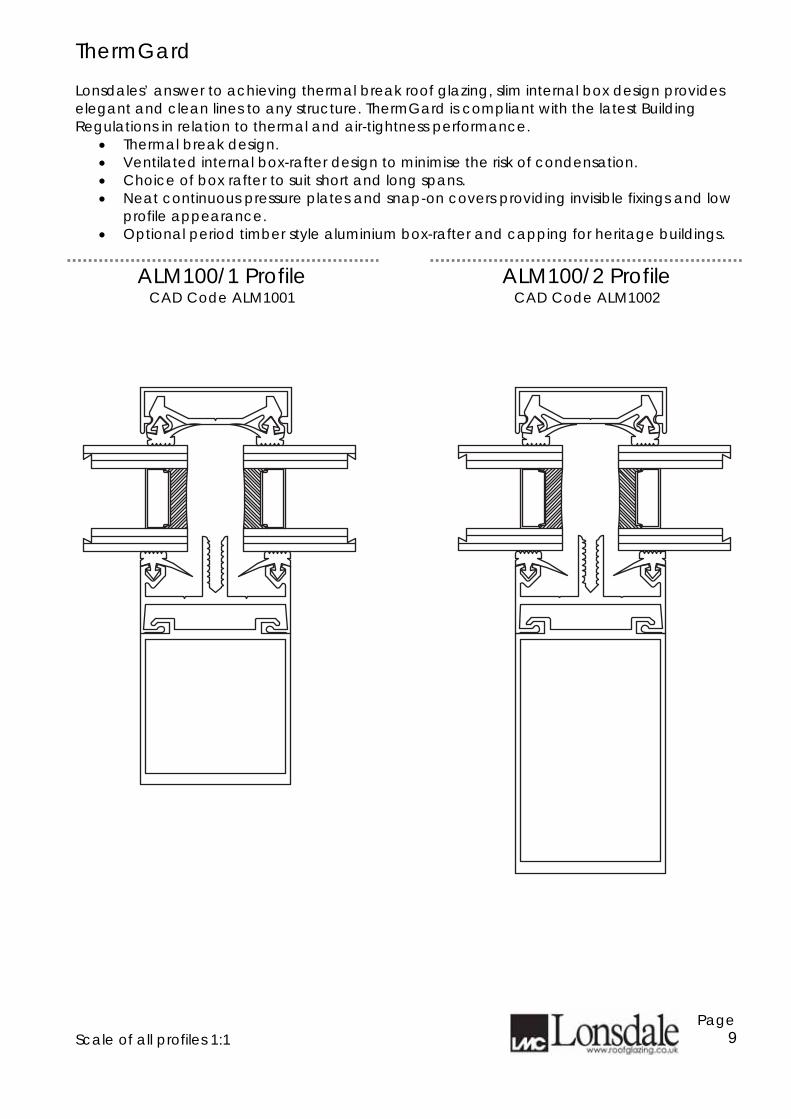
ThermGard Lonsdales’ answer to achieving thermal break roof glazing, slim internal box design provides elegant and clean lines to any structure. ThermGard is compliant with the latest Building Regulations in relation to thermal and air-tightness performance.
• Thermal break design. • Ventilated internal box-rafter design to minimise the risk of condensation. • Choice of box rafter to suit short and long spans. • Neat continuous pressure plates and snap-on covers providing invisible fixings and low
profile appearance. • Optional period timber style aluminium box-rafter and capping for heritage buildings.
ALM100/1 Profile
CAD Code ALM1001 ALM100/2 Profile
CAD Code ALM1002 Scale of all profiles 1:1
Page 9

ThermGard
ALM100/3 Profile CAD Code ALM1003
ALM100/4 Profile CAD Code ALM1004
Scale of all profiles 1:1
Page 10
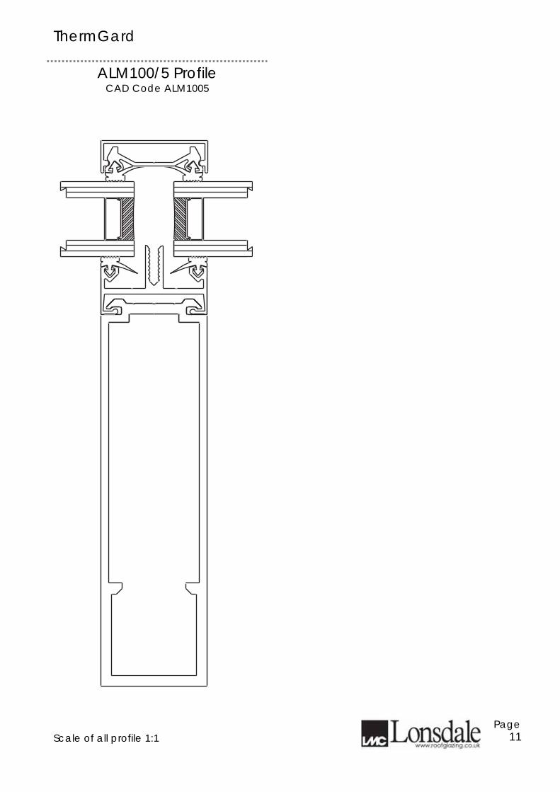
ThermGard
ALM100/5 Profile CAD Code ALM1005
Scale of all profile 1:1
Page 11

ThermGard Bottom slide fixing detail to metal CAD Code BOTSLIDEFIXM
Bottom slide fixing detail to timber CAD Code BOTSLIDEFIXT
Scale of views 1-2
Page 12
Fixing to steel supports is byFixing to steel supports is by
single st.steel M8 nut and boltsingle st.steel M8 nut and bolt
Alternatively,fixing to RHS Alternatively,fixing to RHS
may be achieved by drillingmay be achieved by drilling
and tapping into metaland tapping into metal
supports using the fixing shoesupports using the fixing shoe
and M6 machine screws orand M6 machine screws or
suitable tek fixings at 60 c/ctssuitable tek fixings at 60 c/cts
optional closer foroptional closer for
stepped units isstepped units is
availableavailable
Metal Fixing ShoeMetal Fixing Shoe
Fixing to timber purlin is byFixing to timber purlin is by
2 No. woodscrews thro' shoe2 No. woodscrews thro' shoe
at 60 c/ctsat 60 c/cts
optional closer foroptional closer for
stepped units isstepped units is
availableavailable
Metal Fixing ShoeMetal Fixing Shoe

ThermGard
ALM100/WF Profile CAD Code ALMWF
End Bar CAD Code ENDBAR
Hardwood conservatories The ALM100/WF profile provides the benefits of high performance, weathering and maintenance free roofs to any conservatory, shielding the timber structure from the elements. Fixing to metal supports is by single hole fixing shoe supplied with stainless steel M8 nut and bolt. Alternatively, fixing to RHS may be achieved by drilling and tapping into the metal supports using the fixing shoe and M6 machine screws or suitable TEK screws,
Scale of all profiles 1-1
Page 13
YY
VERGE FLASHING AND VERGE FLASHING AND
INSULATION BOARDINSULATION BOARD
N.B.N.B.
GASKET Y NOT FITTEDGASKET Y NOT FITTED
WHERE VERGE FLASHINGWHERE VERGE FLASHING
IS REQUIREDIS REQUIRED
PVCU thermal barrierPVCU thermal barrier
ALM100 (DG28) CAD Code ALM100DG28
The thermal barrier is optional – please specify when required

ThermGard
ALM100/6 Heritage Profile CAD Code ALM100H6
ALM100/7 Heritage Profile CAD Code ALM100H7
Scale of all profiles 1-1
Page 14

ThermGard
ALM100/8 Heritage Profile CAD Code ALM100H8
ALM100/HCWF Heritage Profile CAD Code ALM100HCWF
Scale of all profiles 1-1
Page 15

ThermGard Top fixing to metal CAD Code THE11MY
Top fixing to timber CAD Code THE11TY
Scale of views 1-2
Page 16
LEAD FLASHINGLEAD FLASHING
LONSDALE GLAZING BARSLONSDALE GLAZING BARS
FIXED TO TIMBER WITH FIXED TO TIMBER WITH
No. 10 WOODSCREW ON C/LNo. 10 WOODSCREW ON C/L
OF BARSOF BARS
CLADDINGCLADDING
POSITIVE TOP FIXING SHOEPOSITIVE TOP FIXING SHOE
RIVETTED TO LONSDALE BAR,RIVETTED TO LONSDALE BAR,
COMPLETE WITH STAINLESS COMPLETE WITH STAINLESS
STEEL M8 SINGLE BOLT FIXINGSTEEL M8 SINGLE BOLT FIXING
ISOLATE DIS-SIMILAR METALSISOLATE DIS-SIMILAR METALS
TOP FIXING TO METALTOP FIXING TO METAL
IF USING RHS MEMBERIF USING RHS MEMBER
USE 2 No. M6 TAPPED ORUSE 2 No. M6 TAPPED OR
2 No. TEK FIXINGS AT 60 C/CTS2 No. TEK FIXINGS AT 60 C/CTS
ABOUT C/L OF BARABOUT C/L OF BAR
LEAD FLASHING DRESSEDLEAD FLASHING DRESSED
ON TO GLASSON TO GLASS
BLACK CO-EX DRAUGHTBLACK CO-EX DRAUGHT
EXCLUDEREXCLUDER
Application
Application

ThermGard Eaves detail to metal CAD Code THE12MY
Eaves detail to timber CAD Code THE12TY
Scale of views 1-2
Page 17
BOTTOM SLIDING SHOEBOTTOM SLIDING SHOE
FIXED WITH 2 No. No. 10 FIXED WITH 2 No. No. 10
WOODSCREWS AT 60 C/CTSWOODSCREWS AT 60 C/CTS
GLASS STOP AS ABOVEGLASS STOP AS ABOVE
OPTIONAL CLOSER FOROPTIONAL CLOSER FOR
STEPPED UNITS ISSTEPPED UNITS IS
AVAILABLEAVAILABLE
BLACK PLASTIC CO-EXBLACK PLASTIC CO-EX
DRAUGHT EXCLUDERDRAUGHT EXCLUDER
OPTIONAL CLOSER FOROPTIONAL CLOSER FOR
STEPPED UNITS ISSTEPPED UNITS IS
AVAILABLEAVAILABLE
BLACK PLASTIC CO-EXBLACK PLASTIC CO-EX
DRAUGHT EXCLUDERDRAUGHT EXCLUDER
BOTTOM SLIDING SINGLE HOLEBOTTOM SLIDING SINGLE HOLE
FIXING SHOE WITH M8 X 25mmFIXING SHOE WITH M8 X 25mm
ST/STEEL BOLTST/STEEL BOLT
ISOLATE DIS-SIMILAR METALSISOLATE DIS-SIMILAR METALSSTANDARD GLASS STOP FIXED TO STANDARD GLASS STOP FIXED TO
BOTTOM OF BAR. NOTE:HEAVY DUTYBOTTOM OF BAR. NOTE:HEAVY DUTY
STOPS ARE REQUIRED WHERE BARSTOPS ARE REQUIRED WHERE BAR
LENGTH IS EQUAL TO OR GREATERLENGTH IS EQUAL TO OR GREATER
THAN 3000mm AND/OR ROOF PITCHTHAN 3000mm AND/OR ROOF PITCH
EXCEEDS 35EXCEEDS 35 EAVES INS
ULATION
EAVES INS
ULATION
AREA
AREA
Application
Application
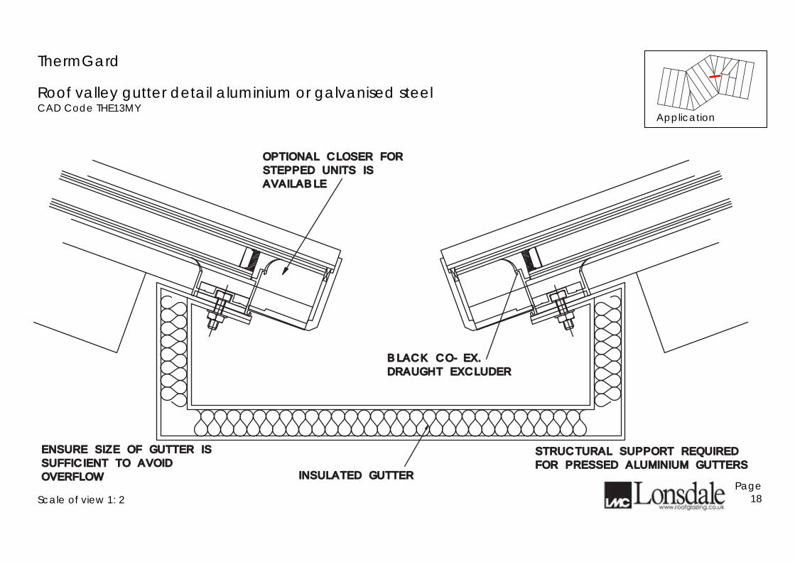
ThermGard
Roof valley gutter detail aluminium or galvanised steel CAD Code THE13MY
Scale of view 1: 2
Page 18
STRUCTURAL SUPPORT REQUIREDSTRUCTURAL SUPPORT REQUIRED
FOR PRESSED ALUMINIUM GUTTERSFOR PRESSED ALUMINIUM GUTTERS
ENSURE SIZE OF GUTTER ISENSURE SIZE OF GUTTER IS
SUFFICIENT TO AVOIDSUFFICIENT TO AVOID
OVERFLOWOVERFLOW INSULATED GUTTERINSULATED GUTTER
BLACK CO-EX.BLACK CO-EX.
DRAUGHT EXCLUDERDRAUGHT EXCLUDER
OPTIONAL CLOSER FOR OPTIONAL CLOSER FOR
STEPPED UNITS ISSTEPPED UNITS IS
AVAILABLEAVAILABLE
Application

ThermGard
Roof valley gutter detail timber lead-lined CAD Code THE13TY
Scale of view 1: 2
Page 19
BLACK CO-EX.BLACK CO-EX.
DRAUGHT EXCLUDERDRAUGHT EXCLUDER
OPTIONAL CLOSER FOR OPTIONAL CLOSER FOR
STEPPED UNITS ISSTEPPED UNITS IS
AVAILABLEAVAILABLE
LEAD LINED GUTTERLEAD LINED GUTTER
Application

ThermGard Parapet CAD Code THE14Y See also Verge THE31Y on page 71
Glass jointing CAD Code 22Y
Scale of views 1-2
Page 20
LONSDALE THERMGARDLONSDALE THERMGARD
SERIES GLAZING BARSERIES GLAZING BAR
CODE 4 LEAD FLASHINGCODE 4 LEAD FLASHING
SILICONE POINTINGSILICONE POINTING
AROUND GLASSAROUND GLASS
THERMALLY BROKEN H CAMETHERMALLY BROKEN H CAME SILICONE POINTINGSILICONE POINTING
AROUND GLASSAROUND GLASS
Application
Application

ThermGard
Ridge/hip detail to metal CAD Code THE18MY
Scale of view 1: 2
Page 21
LONSDALE ADJUSTABLE SECTIONLONSDALE ADJUSTABLE SECTION
TO SUIT VARYING ANGLESTO SUIT VARYING ANGLES
LONSDALE SNAP ON COVERLONSDALE SNAP ON COVER
LONSDALE GLAZING BARLONSDALE GLAZING BAR
FIXED TO STRUCTUREFIXED TO STRUCTURE
POSITIVE TOP FIXING SHOEPOSITIVE TOP FIXING SHOE
RIVETTED TO LONSDALE BAR,RIVETTED TO LONSDALE BAR,
COMPLETE WITH STAINLESSCOMPLETE WITH STAINLESS
STEEL M8 BOLT SINGLE BOLTSTEEL M8 BOLT SINGLE BOLT
FIXING.FIXING.
ISOLATE DIS-SIMILAR METALSISOLATE DIS-SIMILAR METALS
PACK AS REQUIREDPACK AS REQUIRED
4MINMIN
STEEL STRUCTURE NOT BY LONSDALESTEEL STRUCTURE NOT BY LONSDALE
Application

ThermGard
Ridge/hip detail to timber CAD Code THE18TY
Scale of view 1: 2
Page 22
TIMBER STRUCTURE NOT BY LONSDALETIMBER STRUCTURE NOT BY LONSDALE
LONSDALE ADJUSTABLE SECTIONLONSDALE ADJUSTABLE SECTION
TO SUIT VARYING ANGLESTO SUIT VARYING ANGLES
LONSDALE SNAP ON COVERLONSDALE SNAP ON COVER
LONSDALE GLAZING BARLONSDALE GLAZING BAR
FIXED TO STRUCTUREFIXED TO STRUCTURE
PACK AS REQUIREDPACK AS REQUIRED
LONSDALE GLAZING BARSLONSDALE GLAZING BARSFIXED TO TIMBER WITH No.10 x 1FIXED TO TIMBER WITH No.10 x 1
1#1#22 ""
WOODSCREWS THROUGH TOP OFWOODSCREWS THROUGH TOP OFGLAZING BARSGLAZING BARS
Application
1½”

ThermGard
Intermediate roof detail to metal CAD Code THE21MY
Scale of view 1: 2
Page 23
SLIDING SHOE AT INTERMEDIATESLIDING SHOE AT INTERMEDIATE
PURLIN, CAN BE FIXED TO R.S.PURLIN, CAN BE FIXED TO R.S.
SECTION WITH EITHER SINGLESECTION WITH EITHER SINGLE
OR DOUBLE HOLE FIXINGSOR DOUBLE HOLE FIXINGS
(60 C/CTS). IF RHS MEMBER USE(60 C/CTS). IF RHS MEMBER USE
2 No. TAPPED OR 2 No. TEK2 No. TAPPED OR 2 No. TEK
FIXINGS AT 60 C/CTS.FIXINGS AT 60 C/CTS.
ISOLATE DIS-SIMILAR METALSISOLATE DIS-SIMILAR METALS
LONSDALE THERMGARDLONSDALE THERMGARD
SERIES GLAZING BARSERIES GLAZING BAR
INTERMEDIATE PURLININTERMEDIATE PURLIN
LONSDALE BOX SECTION SPANSLONSDALE BOX SECTION SPANS
BETWEEN SUPPORTS AND ISBETWEEN SUPPORTS AND IS
FACTORY FITTED OR POSITIVELYFACTORY FITTED OR POSITIVELY
FIXED ON SITEFIXED ON SITE
Application

ThermGard
Intermediate roof detail to timber CAD Code THE21TY
Scale of view 1: 2
Page 24
SLIDING SHOE AT INTERMEDIATESLIDING SHOE AT INTERMEDIATE
PURLIN, CAN BE FIXED TO TIMBER.PURLIN, CAN BE FIXED TO TIMBER.
WITH 2 No. No. 10 WOODSCREWS WITH 2 No. No. 10 WOODSCREWS
AT 60 C/CTSAT 60 C/CTS
LONSDALE THERMGARDLONSDALE THERMGARD
SERIES GLAZING BARSERIES GLAZING BAR
LONSDALE BOX SECTION SPANSLONSDALE BOX SECTION SPANS
BETWEEN SUPPORTS AND ISBETWEEN SUPPORTS AND IS
FACTORY FITTED OR POSITIVELYFACTORY FITTED OR POSITIVELY
FIXED ON SITEFIXED ON SITE
Application

ThermGard
Tiered roof detail to metal CAD Code THE23MY
Scale of view 1: 2
Page 25
POSITIVE TOP FIXING SHOEPOSITIVE TOP FIXING SHOE
RIVETTED TO LONSDALE BAR,RIVETTED TO LONSDALE BAR,
COMPLETE WITH STAINLESSCOMPLETE WITH STAINLESS
STEEL M8 BOLT SINGLE BOLTSTEEL M8 BOLT SINGLE BOLT
FIXING.FIXING.
ISOLATE DIS-SIMILAR METALSISOLATE DIS-SIMILAR METALS
BLACK CO-EX DRAUGHTBLACK CO-EX DRAUGHT
EXCLUDEREXCLUDER
ALUM GLASS STOP ALUM GLASS STOP
CODE 4 LEAD FLASHINGCODE 4 LEAD FLASHING
DRESSED ONTO GLASSDRESSED ONTO GLASS
LONSDALE THERMGARDLONSDALE THERMGARD
SERIES GLAZING BARSSERIES GLAZING BARS
SLIDING BOTTOM FIXING SHOESLIDING BOTTOM FIXING SHOE
COMPLETE WITH STAINLESSCOMPLETE WITH STAINLESS
STEEL M8 BOLT SINGLE BOLTSTEEL M8 BOLT SINGLE BOLT
FIXING.FIXING.
ISOLATE DIS-SIMILAR METALSISOLATE DIS-SIMILAR METALS
EFFICIENCY
STEELWORK MAY BE INSULATED
BY OTHERS TO IMPROVE THERMAL
Application
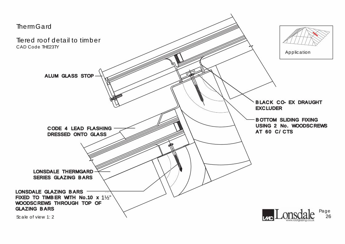
ThermGard
Tiered roof detail to timber CAD Code THE23TY
Scale of view 1: 2
Page 26
BOTTOM SLIDING FIXINGBOTTOM SLIDING FIXING
USING 2 No. WOODSCREWSUSING 2 No. WOODSCREWS
AT 60 C/CTSAT 60 C/CTS
BLACK CO-EX DRAUGHTBLACK CO-EX DRAUGHT
EXCLUDEREXCLUDER
ALUM GLASS STOP ALUM GLASS STOP
CODE 4 LEAD FLASHINGCODE 4 LEAD FLASHING
DRESSED ONTO GLASSDRESSED ONTO GLASS
LONSDALE THERMGARDLONSDALE THERMGARD
SERIES GLAZING BARSSERIES GLAZING BARS
LONSDALE GLAZING BARSFIXED TO TIMBER WITH No.10 x 1
1#2 "
WOODSCREWS THROUGH TOP OFGLAZING BARS
LONSDALE GLAZING BARSFIXED TO TIMBER WITH No.10 x 1
1#2 "
WOODSCREWS THROUGH TOP OFGLAZING BARS
1½”
Application

ThermGard Vertical head fixing to metal CAD Code THE24MY
Vertical head fixing to timber CAD Code THE24TY
Scale of views 1-2
Page 27
POSITIVE TOP FIXING SHOEPOSITIVE TOP FIXING SHOE
GLAZING BARS FIXED WITHGLAZING BARS FIXED WITH
No. 10 WOODSCREW ON C/LNo. 10 WOODSCREW ON C/L
OF BARSOF BARS
PREFORMED ALUMINIUMPREFORMED ALUMINIUM
HEAD FLASHINGHEAD FLASHING
PREFORMED ALUMINIUMPREFORMED ALUMINIUM
HEAD FLASHINGHEAD FLASHING
BLACK CO-EX DRAUGHTBLACK CO-EX DRAUGHT
EXCLUDEREXCLUDER
POSITIVE TOP FIXING SHOEPOSITIVE TOP FIXING SHOE
RIVETTED TO LONSDALE BAR,RIVETTED TO LONSDALE BAR,
COMPLETE WITH STAINLESSCOMPLETE WITH STAINLESS
STEEL M8 BOLT SINGLE BOLTSTEEL M8 BOLT SINGLE BOLT
ISOLATE DIS-SIMILAR METALSISOLATE DIS-SIMILAR METALS
FIXINGFIXING
Application
Application

ThermGard Vertical cill fixing to metal CAD Code THE25MY
Vertical cill fixing to timber CAD Code THE25TY
Scale of views 1-2
Page 28
PREFORMED ALUM ZPREFORMED ALUM Z
CILL FLASHINGCILL FLASHING
ALUM GLASS STOPALUM GLASS STOP
SLIDING BOTTOM SHOESLIDING BOTTOM SHOE
THERMAL EFFICIENCY
STEELWORK MAY BE
NSULATED TO IMPROVE
BLACK CO-EXBLACK CO-EX
DRAUGHT EXCLUDERDRAUGHT EXCLUDER
PREFORMED ALUM ZPREFORMED ALUM Z
CILL FLASHINGCILL FLASHING
ALUM GLASS STOPALUM GLASS STOP
SLIDING BOTTOM SHOESLIDING BOTTOM SHOE
BLACK CO-EXBLACK CO-EX
DRAUGHT EXCLUDERDRAUGHT EXCLUDER
Application
Application

ThermGard Vertical jamb to brickwork CAD Code THE26Y
Verge CAD Code THE31Y
Scale of views 1-2
Page 29
LONSDALE THERMGARDLONSDALE THERMGARD
BOX GLAZING BARBOX GLAZING BAR
LONSDALE THERMGARD SERIESLONSDALE THERMGARD SERIES
END BAR WITH LONSDALEEND BAR WITH LONSDALE
SCREW ON CAP WITH SNAP ONSCREW ON CAP WITH SNAP ON
COVERCOVER
SILICONE SEAL TOSILICONE SEAL TO
BRICKWORKBRICKWORK
LONSDALE THERMGARDLONSDALE THERMGARD
BOX GLAZING BARBOX GLAZING BAR
INSULATED ALUMINIUMINSULATED ALUMINIUM
FLASHING SILICONEFLASHING SILICONE
SEALED TO STRUCTURESEALED TO STRUCTURE
Application
Application

ThermGard Internal corner to vertical CAD Code THE27X
External corner to vertical CAD Code THE28X
Scale of views 1-2
Page 30
LONSDALE THERMGARDLONSDALE THERMGARD
SERIES GLAZING BARSERIES GLAZING BAR
LONSDALE SCREW ON CAPLONSDALE SCREW ON CAP
WITH SNAP ON COVER CAP WITH SNAP ON COVER CAP
ALUM CILLALUM CILL
MITRED AT CORNERMITRED AT CORNER
PRESSED METAL TRAYEDPRESSED METAL TRAYED
FOLDINGS (INSULATEDFOLDINGS (INSULATED
IF REQUIRED)IF REQUIRED)
PRESSED METAL TRAYEDPRESSED METAL TRAYED
FOLDINGS (INSULATEDFOLDINGS (INSULATED
IF REQUIRED)IF REQUIRED)
LONSDALE SCREW ON CAPLONSDALE SCREW ON CAP
WITH SNAP ON COVER CAP WITH SNAP ON COVER CAP
LONSDALE THERMGARDLONSDALE THERMGARD
SERIES GLAZING BARSERIES GLAZING BAR
Application
Application

ThermGard Vertical intermediate detail CAD Code THE29Y
Scale of views 1-2
Page 31
SLIDING SHOESLIDING SHOE
BLACK CO-EXBLACK CO-EX
DRAUGHT EXCLUDERDRAUGHT EXCLUDER
ALUM GLASS STOPALUM GLASS STOP
PREFORMED ALUM ZPREFORMED ALUM Z
INTERMEDIATEINTERMEDIATE
FLASHINGFLASHING
BLACK CO-EXBLACK CO-EX
DRAUGHT EXCLUDERDRAUGHT EXCLUDER
POSITIVE FIXING SHOEPOSITIVE FIXING SHOE
(DELETE WHEN FIXING(DELETE WHEN FIXING
TO TIMBER AND SCREWTO TIMBER AND SCREW
CARRIER RAIL DIRECT TOCARRIER RAIL DIRECT TO
SUPPORT WITH 2No.No.10SUPPORT WITH 2No.No.10
WOODSCREWS)WOODSCREWS)
EFFICIENCY
STEELWORK MAY BE INSULATED
BY OTHERS TO IMPROVE THERMAL
Application

ThermGard
Top detail into tile or slate roof CAD Code THE34-TR
Scale of view 1: 2
Page 32
PROFILED CONC ROOF TILES OR SLATESPROFILED CONC ROOF TILES OR SLATES
TILE BATTENTILE BATTEN
ROOFING FELT EXTENDEDROOFING FELT EXTENDED
TO DRAIN OVER GLASSTO DRAIN OVER GLASS
ROOF JOIST ANDROOF JOIST AND
GLAZING PURLINGLAZING PURLIN
BLACK PLASTIC CO-EXBLACK PLASTIC CO-EX
DRAUGHT EXCLUDERDRAUGHT EXCLUDER
CODE 4 LEAD FLASHINGCODE 4 LEAD FLASHING
DRESSED ONTO GLASSDRESSED ONTO GLASS
No.10 x 11#2 " WOODSCREWS
THROUGH TOP OF GLAZING BARSNo.10 x 1
1#2 " WOODSCREWS
THROUGH TOP OF GLAZING BARS
1½”
Application

ThermGard
Bottom detail into tile or slate roof CAD Code THE35-TR
Scale of view 1: 2
Page 33
PROFILED CONC TILESPROFILED CONC TILES
TILE BATTENTILE BATTEN
ROOFING FELTROOFING FELT
ROOF JOISTROOF JOIST
CODE 4 LEAD FLASHINGCODE 4 LEAD FLASHING
BLACK CO-EXTRUDEDBLACK CO-EXTRUDED
DRAUGHT EXCLUDERDRAUGHT EXCLUDER
BOTTOM SLIDING FIXINGBOTTOM SLIDING FIXING
USING 2 No. WOODSCREWSUSING 2 No. WOODSCREWS
AT 60 C/CTSAT 60 C/CTSOR SLATESOR SLATES
OPTIONAL CLOSER FOROPTIONAL CLOSER FOR
STEPPED UNITS AVAILABLESTEPPED UNITS AVAILABLE
ALUM GLASS STOP ALUM GLASS STOP
Application

ThermGard
Jamb detail into tile or slate roof CAD Code THE36-TR
Scale of view 1: 2
Page 34
CODE 4 LEAD FLASHINGCODE 4 LEAD FLASHING
DRESSED ONTO GLASSDRESSED ONTO GLASS
LONSDALE THERMGARDLONSDALE THERMGARD
BOX GLAZING BARBOX GLAZING BAR
LONSDALE THERMGARDLONSDALE THERMGARD
END BAR WITH LONSDALEEND BAR WITH LONSDALE
SCREW ON CAP AND SNAPSCREW ON CAP AND SNAP
ON COVER SECTIONON COVER SECTION
ROOFING FELTROOFING FELT
TILE BATTENTILE BATTEN
ROOF JOISTROOF JOIST
TILES OR SLATESTILES OR SLATES
Application

GlazaTherm Sizing matrix Approximate Geometric Free Air Area m² Based upon open actuator stroke lengths 300mm and 550mm
Width W mm** Length L mm* 600 700 800 900 1000 1100 1200
0.28 0.31 0.34 0.37 0.40 0.43 0.46 600 0.50 0.56 0.61 0.67 0.72 0.78 0.83 0.31 0.34 0.37 0.40 0.43 0.46 0.49 700 0.56 0.62 0.67 0.73 0.78 0.84 0.89 0.34 0.37 0.40 0.43 0.46 0.49 0.52 800 0.61 0.67 0.72 0.78 0.83 0.89 0.94 0.37 0.40 0.43 0.46 0.49 0.52 0.55 900 0.67 0.73 0.78 0.84 0.89 0.95 1.00 0.40 0.43 0.46 0.49 0.52 0.55 0.58 1000 0.72 0.78 0.83 0.89 0.94 1.00 1.05 0.43 0.46 0.49 0.52 0.55 0.58 0.61 1100 0.78 0.84 0.89 0.95 1.00 1.06 1.11 0.46 0.49 0.52 0.55 0.58 0.61 0.64 1200 0.83 0.89 0.94 1.00 1.05 1.11 1.16 0.55 0.58 0.61 0.64 0.67 0.70 0.73 1500 1.00 1.06 1.11 1.17 1.22 1.28 1.33 0.64 0.67 0.70 0.73 0.76 0.79 0.82 1800 1.16 1.22 1.27 1.33 1.38 1.44 1.49 0.70 0.73 0.76 0.79 0.82 0.85 0.88 2000 1.27 1.33 1.38 1.44 1.49 1.55 1.60 0.82 0.85 0.88 2400 1.49 1.55 1.60
**Dimension L mm = overall fixed frame length – see drawings on page 37. **Dimension W mm = overall fixed frame width – see drawings on pages 38. Side hung vents are restricted to 1.20m² (Width x Length) with a maximum overall fixed frame length of 1800mm. IF THE SIZE REQUIRED IS OUTSIDE THE BOUNDRIES OF THE ABOVE MATRIX PLEASE CONTACT OUR SALES OFFICE. Please note : Whilst we are pleased to assist, the above example is given for guidance only. Responsibility remains with Specifiers to exercise all reasonable care ensuring our products are suitable for their requirements and correctly specified. GlazaTherm Drawings and CAD Code Index Drawing number CAD code
Description Page
GLAZ1PG GLAZ2PGCW GLAZ3CW GLAZ4CW GLAZ5PG
Top & bottom detail two edge support patent glazing Side rail into typical patent glazing or sloped curtain wall Bottom detail into typical curtain wall transom Head detail into typical curtain wall transom Vent top detail with glass above
37 38394040
GlazaTherm – suitable for 24 – 28mm Double Glazed Units or 25mm polycarbonate
Page 35

GlazaTherm ordering information Top hung roof ventilator
When ordering GlazaTherm to fit other manufacturers glazing bars or sloped 4-edge support systems, please specify fixed frame width and length. See notes below.
• GlazaTherm inserts between most patent glazing bars, sloped curtain walling and conservatory roof systems currently available.
• Suitable for single glazing, sealed double glazed units and Polycarbonate sheeting. • Standard size 610mm x 915mm. Please contact our Sales Office for details of non-
standard sizes. • Manufactured from extruded aluminium alloy 6063-T6 sections supplied mill finish as
standard and thermally broken with polyamides extrusions. • Polyester powder paint finishes available in a wide range of colours. • Various factory-fitted opening mechanisms, including pole, cord, thermostatic,
electric and smoke actuators. • Complies with BS5516 when used within manufacturers recommendations.
Dimensions required when ordering please state: 0/A Fixed Frame Length (Dimension L - refer drawings on page 37) 0/A Fixed Frame Width (Dimension W - refer drawings on page 38) Sectional views L-L = 0/A Fixed Frame Length - Dimension L W-W = 0/A Fixed Frame Width - Dimension W
Page 36
Application
x
L
L
W
W

GlazaTherm
Top and bottom detail two edge support Patent Glazing CAD Code GLAZ1PG
Scale of view 1: 2
Page 37
2424
4040
Dimensi
on L
Dimensi
on L
SILICONE SEALANTSILICONE SEALANT
2mm ADHESIVE FOAM TAPE2mm ADHESIVE FOAM TAPE
PACKINGPACKING
SILICONE SEALANTSILICONE SEALANT
LEAD FLASHINGLEAD FLASHING
SILICONE SEALANTSILICONE SEALANT
2mm ADHESIVE FOAM TAPE2mm ADHESIVE FOAM TAPE
PACKINGPACKING
SILICONE SEALANTSILICONE SEALANT
PLASTIC H CAME SEPARATORPLASTIC H CAME SEPARATOR
SILICONE SEALANT & PACKINGSILICONE SEALANT & PACKINGREPEATED TO BOTH SIDES OFREPEATED TO BOTH SIDES OFLOWER H CAME.LOWER H CAME.SILICONE SEALANT & PACKERSSILICONE SEALANT & PACKERSBY OTHERS.BY OTHERS.
THERMAL LINERTHERMAL LINER

GlazaTherm
Side rail into Patent Glazing bar or sloping curtain walling CAD Code GLAZ2PGCW
Scale of view 1: 2
Page 38
Dimension WDimension W
28mm Ventilator Sections28mm Ventilator Sections
THERMAL LINERTHERMAL LINER

GlazaTherm
Bottom detail into typical curtain wall transom CAD Code GLAZ3CW
Scale of view 1: 2
Page 39
28mm Ventilator Sections28mm Ventilator Sections
THERMAL LINERTHERMAL LINER

GlazaTherm Head detail into typical curtain wall transom CAD Code GLAZ4CW
Vent detail with glass above CAD Code GLAZ5PG
Scale of views 1-2
Page 40
28mm Ventilator Sections28mm Ventilator Sections
THERMAL LINERTHERMAL LINER
4040
28mm Ventilator28mm VentilatorTop DetailTop Detail
Silicone sealant and packersSilicone sealant and packersby othersby others
THERMAL LINERTHERMAL LINER
SILICONE SEALANTSILICONE SEALANT
2mm ADHESIVE FOAM TAPE2mm ADHESIVE FOAM TAPE
PACKINGPACKING
SILICONE SEALANTSILICONE SEALANT
SILICONE SEALANTSILICONE SEALANT

Research & Development Lonsdale has made a very significant investment in research and development to bring you the products set out in this publication. Lonsdale's intention is to continue to invest to stay at the fore front of its Industry and bring its customers products with unrivalled technological advancements and standards. We reserve the right to make changes without prior notification to achieve these aims. Lonsdale will attack any Infringement of its copyright in order that both its customers and the Company may obtain the full benefits of its endeavours. Any unauthorised copying or reproduction of the plans and ideas whose copyright belongs to Lonsdale in this brochure will be met by legal action from the Company's solicitors Messrs. H. Montlake & Co. February 2009
www.roofglazing.co.uk Page 41