lorenz-based chaotic secure communication schemes · lorenz-based chaotic secure communication...
TRANSCRIPT

LORENZ-BASED CHAOTIC SECURE COMMUNICATION
SCHEMES
I.A. Kamil and O.A. Fakolujo
Department of Electrical and Electronic Engineering
University of Ibadan, Nigeria
ABSTRACT
Secure communication systems employing chaos have recently attracted
significant interest. This is partly due to their high unpredictability and
simplicity of implementation over conventional secure communications
systems. This study presents the implementation of four chaotic modulation
techniques employing Lorenz system as chaos generator. The techniques are
Chaotic Masking (CM), Chaos Shift Keying (CSK), Chaos On-Off Keying
(COOK), and Differential Chaos Shift Keying (DCSK). Simulations were
carried out using Simulink in Matlab environment to implement these
techniques. A qualitative evaluation of the transmitted signal waveforms in
all the cases considered showed that DCSK gives the highest level of
security followed by CSK while COOK gives the least level of security.
Keyword: Secure communication, Chaos, Lorenz system, Modulation
1. INTRODUCTION
Recent years have witnessed appreciable growth in
personal communications most especially in the area
of mobile communication and the internet [1,2]. Data
encryption and security are essential ingredients of
personal communication that are recently receiving
attention because of the need to ensure that the
information being sent is not intercepted by an
unwanted listener. Besides, these are very essential
for protecting the content integrity of a message as
well as its copyright [2].
A secure communication system as it is generally
called, transforms the information signal in such a
way that only an authorized receiver who has a prior
knowledge of the transformation parameters can
receive the information. The security of this
information is a measure of the difficulty
encountered by an unauthorized interceptor who
attempts to decode it. There have been a good
number of approaches to secure communications
reported in the literature, but most of the commonly
employed conventional encryption and security
schemes are complex in hardware [3,4]. A secure
communication is not only a system where privacy is
ensured, it must also ensure the integrity of the
transmitted message i.e. the exact information meant
for the receiver is received.
Chaos based secure communication has been of
much interest in the recent time since it offers
potential advantage over conventional methods due
to its simplicity [3] and high unpredictability which
means higher security. Besides, analog
implementation is possible [5].
Many chaotic secure communication schemes have been reported in literature but only a few of them have actually witnessed practical implementation. This paper attempts to model and simulate four of these schemes using Simulink in Matlab. The choice of Simulink was to bring the schemes as close to practical implementation as possible since each Simulink block can easily be replaced by a practical unit. The four schemes considered were Chaotic Masking, Chaos On-Off Keying, Chaos Shift Keying and Differential Shift Keying.
Ubiquitous Computing and Communication Journal
Volume 7 Number 2 Page 1248 www.ubicc.org

2. THEORY
2.1. Background
Chaos communication is rather a new field in the
communication research. It evolved from the study
of chaotic dynamical systems, not only in
mathematics, but also in physics or electrical
engineering somewhere at the beginning of 1990 [6].
Prior to this period, the evolution of chaos has caused
much euphoria among the mathematicians and
physicists, while the engineering community has
observed the development with skepticism.
Chaotic signals are irregular, aperiodic,
uncorrelated, broadband, and impossible to predict
over long times. These properties coincide with the
requirements for signals applied in conventional
communication systems, in particular spread-
spectrum communications, multi-user
communications, and secure communication.
2.2. Chaotic System
The chaotic system employed in this work is the
Lorenz system One of the earliest indications of
chaotic behaviour was developed by Edward N.
Lorenz in the 60’s [7]. [8] stated that the Lorenz
system was published as a model of two-dimensional
convection in a horizontal layer of fluid heated from
below. The original equations for this 3rd
–order non-
linear system are [9-12]:
�� = −�� + ��
�� = �� − � − � (1)
� = − + ��
where x, y and z are the variables and σ, r and b are
dimensionless parameters usually assumed positive.
Varying the values of the parameters leads to series
of bifurcation and eventually chaos. Typical
parameter values are σ=10, b=8/3 and r=20 [9].
2.3. Chaos Modulation Schemes
Four modulation schemes considered in this paper
are Chaotic Masking (CM), Chaos On-Off Keying
(COOK), Chaos Shift Keying (CSK) and Differential
Chaos Shift Keying (DCSK).
2.3.1 Chaotic Masking
In chaotic masking, two identical chaotic are used:
one at the transmitter end and the other at the
receiver. As shown in Fig. 1, the message signal m(t)
is added to the chaotic mask signal c(t) giving the
transmitted signal s(t). The chaotic system at the
receiver end produces another copy of the chaotic
mask signal �̂(�) which is subtracted from the
transmitted signal r(t) to obtain the recovered
message signal ��(�).
Assuming a noise free channel and perfect
synchronization between the two chaotic systems,
s(t)=r(t), c(t)= �̂(�) and m(t)= ��(�).
For higher security of the message signal, Yang
reported that the message signal is typically made
about 20dB to 30dB weaker than the chaotic signal
[13].
2.3.2 Chaos Shift Keying
In this modulation scheme, the message signal,
which is a digital signal, is used to switch the
transmitted signal between two statistically similar
attractors ��(�) and ��(�) which are respectively
used to encode bit 0 and bit 1 of the message signal.
The two attractors are generated by two chaotic
systems with the same structure but different
parameters [13, 14].
At the receiver end, the received signal is
correlated with a synchronized reproduction of any
of the two chaotic signals used in the transmitter. The
message signal is recovered by low-pass filtering and
threshholding the synchronization error. The block
diagram representation of the scheme is shown in
Fig. 2.
2.3.3 Chaos On-Off Keying
Chaos On-Off Keying is similar to CSK in all
respects except that only one chaotic signal is used in
transmission of message signal. When the message
signal is bit 1, the chaotic signal is transmitted, but
when the message signal is bit 0 no signal is
transmitted. The same procedure is used in
demodulating the received signal as in CSK as
shown in Fig. 3.
RECEIVER TRANSMITTER
chaotic
messag
e
channel
cha
oti
c sy
nch
ron
iza
tio
n
chaotic
recovered
message
m(t)
c(t) s(t) r(t)
�̂(�) ��(�)
Figure 1: Chaotic Masking
Ubiquitous Computing and Communication Journal
Volume 7 Number 2 Page 1249 www.ubicc.org

2.3.4 Differential Chaos Shift Keying
In Differential Chaos Shift Keying, no
synchronization is required as in the other three
schemes earlier described. The same chaotic signal
used at the transmitter (called reference signal) is
transmitted and used to demodulate the message
signal at the receiver end. This is illustrated in Fig. 4.
In this scheme, every bit is transmitted two sample
functions. The first sample function serves as the
reference while the second one carries the
information. Thus, bit 1 is sent by transmitting the
reference signal twice in succession and bit 0 is sent
by transmitting the reference signal followed by an
inverted copy of the reference signal. The two
sample functions are correlated in the receiver and
the decision is made by thresholding [15].
3. SIMULATION
3.1. Lorenz system
Cuomo et al observed that a direct
implementation of Eq.(1) with an electronic circuit is
difficult because the state variables in Eq.(1) occupy
a wide dynamic range with values that exceed
reasonable power supply limits [16]. However, this
difficulty can be eliminated by a simple
transformation of variables; specifically, for the
coefficients
σ, r, and b used, an appropriate transformation is
u=x/10, v=y/10, and w=z/10. With this scaling, the
Lorenz equations are transformed to:
�� = �(� − �)
�� = �� − � − 20�� (2)
�� = 5�� − �
The above equation was implemented using
Simulink with the parameter values taken as σ=16,
r=45.6, and b=4 .The time series for the three state
variables is shown in Fig. 5.
3.2. Self Synchronization of Lorenz system
The receiver is made up of two stable subsystems
decomposed from the original system using Pecora
& Carrol Scheme [16-19]. In the second approach
using v as the drive signal, the first subsystem, (u′), is
given by:
�′� = �(� − �′) (3)
The second response subsystem, (� ′, �′), is given by:
�′� = ��′ − �� − 20�′�′
�′� = 5�′�′ − �′ (4)
RECEIVER TRANSMITTER
chaotic
system 1
message
signal
channel
cha
oti
c sy
nch
ron
iza
tio
n
chaotic
system
LPF and
thresholding
recovered
message
chaotic
system 2
�1(�)
�2(�)
�(�)
�(�)
�� (�)
1
2
Figure 3: Chaos Shift Keying
RECEIVER TRANSMITTER
!"
#
-1
!"
#
channel
LP
F a
nd
th
resh
old
ing
Re
co
ve
red
me
ssa
ge
sig
na
l
chaotic
system
message
signal
Clock, Tb Clock, Tb
Delay
Block
Delay
Block
Figure 4: Differential Chaos Shift Keying
RECEIVER TRANSMITTER
chaotic
system 1
message
signal
channel
chao
tic
syn
chro
niz
ati
on
chaotic
system
LPF and
thresholding
recovered
message
0
0
Figure 2: Chaos On-Off Keying
Ubiquitous Computing and Communication Journal
Volume 7 Number 2 Page 1250 www.ubicc.org

The complete response system is therefore given by:
�′� = �(� − �′)
�′� = �� − �′ − 20�′�′ (5)
�′� = 5�′�′ − �
Since the two subsystems are stable, �≈�′ as t→∞.
Thus synchronization is achieved. The transmitter and the receiver systems were
modeled with Simulink. For the transmitter, the
initial conditions were u(0)=200, v(0)=1 and w(0)=1
and for the receiver, the initial conditions
were ��(0) = 250, ��(0) = 1 and �(0) = 1. A
parameter variation of 0.1 was also introduced
between the transmitter and receiver systems. The
time series and orbit difference for the two systems
are as shown in Fig. 6.
3.3. Chaos Modulation Schemes
The four schemes earlier described were modeled and simulated with Simulink using self-synchronized Lorenz system. The simulation results are shown in Figs. 7 to 10.
Figure 5: Lorenz system time series (a) u (b) v (c) w
0 0.5 1 1.5 2 2.5 3 3.5 4 4.5 5
x 10-4
-5
0
5
u
y
0 0.5 1 1.5 2 2.5 3 3.5 4 4.5 5
x 10-4
-5
0
5
v
0 0.5 1 1.5 2 2.5 3 3.5 4 4.5 5
x 10-4
0
2
4
Time
w
(a)
(b)
(c)
0 0.5 1 1.5 2 2.5 3 3.5 4 4.5 5
x 10-4
-5
0
5
v/v
'
y
0 0.5 1 1.5 2 2.5 3 3.5 4 4.5 5
x 10-4
-2
0
2
Time
(v'-
v)
v'
v
(a)
(b)
(b)
(a)
Figure 6: Self synchronization of two Lorenz systems using v as drive signal with different initial
conditions and parameter values, (a) Time series of v and v’ (b) Synchronization Error.
Ubiquitous Computing and Communication Journal
Volume 7 Number 2 Page 1251 www.ubicc.org
0 0.5 1 1.5 2 2.5 3 3.5 4 4.5 5
x 10-3
-5
0
5
(a)
0 0.5 1 1.5 2 2.5 3 3.5 4 4.5 5
x 10-3
-10
0
10(b)
0 0.5 1 1.5 2 2.5 3 3.5 4 4.5 5
x 10-3
0.5
1(c)
0 0.5 1 1.5 2 2.5 3 3.5 4 4.5 5
x 10-3
-0.50
0.51
1.5
(d)
0 0.5 1 1.5 2 2.5 3 3.5 4 4.5 5
x 10-3
-0.50
0.51
1.5
Time
(e)
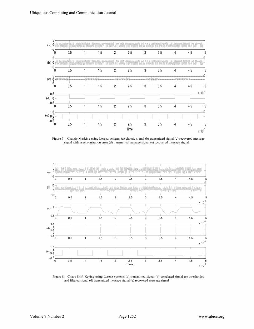
Figure 8: Chaos Shift Keying using Lorenz systems (a) transmitted signal (b) correlated signal (c) thresholded
and filtered signal (d) transmitted message signal (e) recovered message signal
0 0.5 1 1.5 2 2.5 3 3.5 4 4.5 5
x 10-3
-5
05
0 0.5 1 1.5 2 2.5 3 3.5 4 4.5 5
x 10-3
-5
05
0 0.5 1 1.5 2 2.5 3 3.5 4 4.5 5
x 10-3
-0.5
00.5
0 0.5 1 1.5 2 2.5 3 3.5 4 4.5 5
x 10-3
-0.50
0.51
1.5
Time
0 0.5 1 1.5 2 2.5 3 3.5 4 4.5 5
x 10-3
-505
(a)
(b)
(c)
(d)
(e)
Figure 7: Chaotic Masking using Lorenz systems (a) chaotic signal (b) transmitted signal (c) recovered message
signal with synchronization error (d) transmitted message signal (e) recovered message signal
Ubiquitous Computing and Communication Journal
Volume 7 Number 2 Page 1252 www.ubicc.org
0 0.5 1 1.5 2 2.5 3 3.5 4 4.5 5
x 10-3
-5
0
5
(a)
0 0.5 1 1.5 2 2.5 3 3.5 4 4.5 5
x 10-3
-5
0
5
(b)
0 0.5 1 1.5 2 2.5 3 3.5 4 4.5 5
x 10-3
012
(c)
0 0.5 1 1.5 2 2.5 3 3.5 4 4.5 5
x 10-3
-0.50
0.51
1.5(d)
0 0.5 1 1.5 2 2.5 3 3.5 4 4.5 5
x 10-3
-0.50
0.51
1.5
Time
(e)
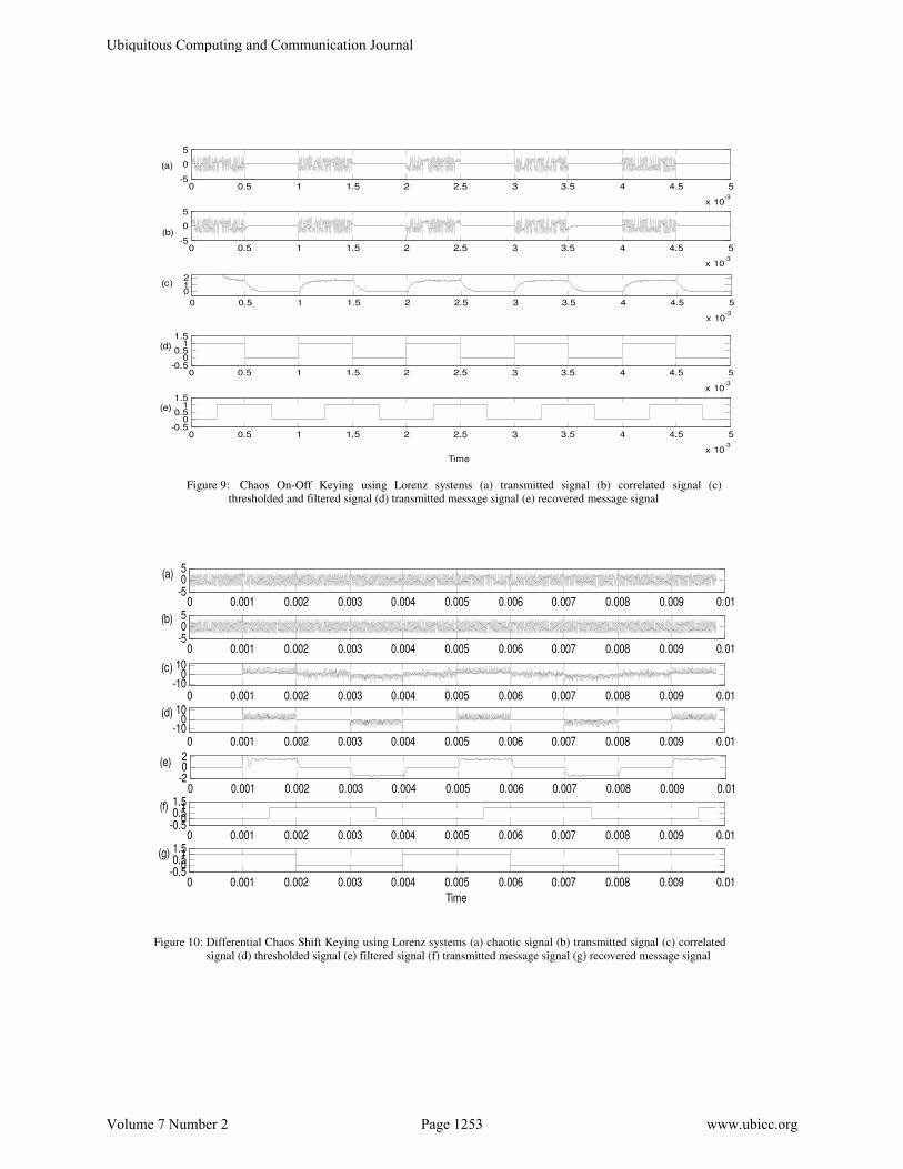
Figure 9: Chaos On-Off Keying using Lorenz systems (a) transmitted signal (b) correlated signal (c)
thresholded and filtered signal (d) transmitted message signal (e) recovered message signal
0 0.001 0.002 0.003 0.004 0.005 0.006 0.007 0.008 0.009 0.01-505(a)
0 0.001 0.002 0.003 0.004 0.005 0.006 0.007 0.008 0.009 0.01-505(b)
0 0.001 0.002 0.003 0.004 0.005 0.006 0.007 0.008 0.009 0.01-10
010(c)
0 0.001 0.002 0.003 0.004 0.005 0.006 0.007 0.008 0.009 0.01-10
010(d)
0 0.001 0.002 0.003 0.004 0.005 0.006 0.007 0.008 0.009 0.01-202(e)
0 0.001 0.002 0.003 0.004 0.005 0.006 0.007 0.008 0.009 0.01-0.5
00.511.5(f)
0 0.001 0.002 0.003 0.004 0.005 0.006 0.007 0.008 0.009 0.01-0.5
00.511.5
Time
(g)
Figure 10: Differential Chaos Shift Keying using Lorenz systems (a) chaotic signal (b) transmitted signal (c) correlated
signal (d) thresholded signal (e) filtered signal (f) transmitted message signal (g) recovered message signal
Ubiquitous Computing and Communication Journal
Volume 7 Number 2 Page 1253 www.ubicc.org
4. DISCUSSIONS
The results obtained in Fig 6 showed that a
difference in initial conditions and slight parameter
variation that would otherwise cause the two chaotic
systems to produce divergent time series, had no
effect when the two were synchronized using self
synchronization approach.
Figs. 7, 8, 9 and 10 confirmed the effectiveness of
the four modulation schemes as the message signals
were recovered at the receiver. The transmitted signal
waveforms confirmed the security of the chaos
modulation schemes. It could be observed that DCSK
provided the highest security followed by chaotic
masking. COOK provided the lowest level of security.
The data transmission rate of DCSK was however
twice those of others.
5. CONCLUSSION
We have discussed in this paper the use of Simulink
to demonstrate various chaotic secure communication
schemes. We have assumed an ideal noiseless
communication channel in this study. Further work is
on going to demonstrate same for a practical noisy
channel.
6. REFERENCES
[1] M. P. Kennedy, R. Rovatti, and G. Setti,
Chaotic Electronics In Telecommunications.
Boca Raton: CRC Press LLC, 2000.
[2] W. Bender, N. Gruhi, A. Morimoto, and H.
Lu, "Techniques in Data Hiding " IBM
Systems Journal, vol. Vol. 35, pp. pp 313-
336, 1996.
[3] M. Itoh, "Spread Spectrum Communication
Via Chaos " Int. Jour. of Bifurc. & Chaos,
vol. Vol. 9, pp. pp. 155-213, 1999.
[4] A. R. Volkovskii, L. S. Tsimring, N. F.
Rulkov, and I. Langmore, "Spread Spectrum
Communication System with Chaotic
Frequency Modulation," Chaos, vol. Vol. 15,
pp. pp. 1-6, 2005.
[5] L. S. Tsimring and R. Tenny, "Security
Issues in Chaos-based Communication and
Encryption”, ," Proc. of Winter School on
Chaotic Communication, Institute for
Nonlinear Science, UCSD, 2003.
[6] A. Abel and W. Schwarz, "Chaos
Communications – Principles, Schemes and
Systems," Proc. IEEE, vol. vol. 90, no. 1, pp.
p.691-709, 2002.
[7] E. N. Lorenz, "Deterministic non-periodic
flow," Journal of Atmo. Sci., vol. Vol. 20, pp.
pp. 130-141, 1963.
[8] P. G. Drazin, Nonlinear Systems Cambridge
University Press., 1992.
[9] Y. Gauthier, "Application of the Lorenz
Chaotic System to Secure Communication
and Encryption," Carleton University., 1998.
[10] http://en.wikipedia.org/wiki/Lorenz_attractor,
"Lorenz Attractor," Wikipedia, the free
encyclopedia, 2008.
[11] C. Sparrow, "The Lorenz Equations," Chaos,
ed. A.V. Holden, Princeton Univ. Press,
1986.
[12] E. Sánchez and M. A. Maltiás, "Transition to
Chaotic Rotating Waves in Arrays of
Coupled Lorenz Oscillators," Int. Jour. of
Bifurc. & Chaos, vol. Vol. 9, pp. pp. 2335-
2343, 1999.
[13] T. Yang, "A Survey of Chaotic Secure
Communication Systems," Int. Jour. of
Comp. Cognition, vol. Vol. 2, pp. pp 81-130,
2004.
[14] H. Yu and H. Leung, "A Comparative Study
of Different Chaos Based Spread Spectrum
Communication Systems," Proc. IEEE Int.
Symp. Cct. & Syst. (ISCAS 2001), vol. Vol. 2,
pp. pp. 213-216, 2001.
[15] G. Kolumban, M. P. Kennedy, and L. O.
Chua, "The Role of Synchronization in
Digital Communications Using Chaos – Part
II: Chaotic Modulation and Chaotic
Synchronization," IEEE Trans. Circuits &
Syst. I: Fund. Theory & Appli., vol. Vol. 45,
pp. pp. 1129-1140, 1998.
[16] K. M. Cuomo, A. V. Oppenheim, and S. H. Strogatz, "Synchronization of Lorenz-Based Chaotic Circuits with Applications to Communications," IEEE Trans. Circuits &
Syst. II - Analog & Digital Signal
Processing, vol. Vol. 40, pp. pp. 626-633, 1993.
[17] S. Boccaletti, A. Farini, and F. T. Arecchi, "Adaptive Synchronization of Chaos for Secure Communication ." Phy. Rev. E, vol. Vol 55, pp. pp. 4979-4981, 1997.
[18] T. L. Carroll, "Communicating with Use of Filtered, Synchronized, Chaotic Signals," IEEE Trans. Cct. & Sys. I- Fund. Theo. & Appl., vol. Vol. 42, pp. pp. 105-110, 1995.
[19] L. M. Pecora and T. L. Carroll, "Synchronization in Chaotic Systems," Phy. Rev. Lett., vol. Vol 64, pp. pp. 821-824, 1990.
Ubiquitous Computing and Communication Journal
Volume 7 Number 2 Page 1254 www.ubicc.org