low cost high-h2 syngas production for power and liquid …
TRANSCRIPT

1
FINAL TECHNICAL REPORT
January 1, 2014, through December 31, 2014
Project Title: LOW COST HIGH-H2 SYNGAS PRODUCTION FOR POWER
AND LIQUID FUELS
ICCI Project Number: 14/US-2
Principal Investigator: Razima Souleimanova, Gas Technology Institute
Project Manager: Debalina Dasgupta, ICCI
ABSTRACT
The overall objective was to determine the technical and economic feasibility of a
systems approach for producing high hydrogen syngas from coal with the potential to
reduce significantly the cost of producing power, chemical-grade hydrogen or liquid
fuels, with carbon capture and reducing the environmental impact of gasification. The
study results are:
(1) Experimental work to determine the technical feasibility of a novel hybrid
polymer/metal H2-membrane to recover pure H2 from a coal-derived syngas was
conducted. This task was not successful. Although membranes were synthesized, they
were impermeable for all gases under all applied conditions.
(2) Bench-scale experimental work was performed to extend GTI's current database on
the University of California Sulfur Recovery Process-High Pressure (UCSRP-HP) for
syngas cleanup including removal of sulfur and other trace contaminants, such as,
chlorides and ammonia. The UCSRP-HP process tests show >90% H2S conversion with
outlet H2S concentrations less than 4 ppmv, and 80-90% ammonia and chloride removal
with high mass transfer rates.
(3) Techno-economic analyses were done for the production of electric power, chemical-
grade hydrogen and diesel fuels, from a mixture of coal plus natural gas using the AR
compact gasifier with integration of the H2-membrane and UCSRP-HP technologies.
Results and key conclusions from this research are:
Using overall energy input of 53% coal and 47% natural gas to a plant producing
~9,609 BSD of diesel and naphtha at ~56 vol. % diesel with GTI’s UCSRP-HP
process for sulfur removal, breakeven Brent Crude Price (BCP) would be reduced
by about 30%. The total CAPEX reduces by ~29% as compared with DOE Case
reported in DOE/NETL Report # 2007/12531.
For chemical-grade hydrogen production with carbon capture case, the GTI
process showed a 10% reduction in the price of H2 resulting in a $21,000,000
saving per year.
For IGCC plant with carbon capture case, the GTI process showed savings in
CAPEX and OPEX resulting in a reduction in LCOE (~15%).

2
EXECUTIVE SUMMARY
The overall objective of this project was to determine the technical and economic
feasibility of an integrated systems approach for producing high hydrogen syngas from
coal. This has the potential to reduce the cost of producing power, chemical-grade
hydrogen or liquid fuels, with carbon capture and the environmental impact of
gasification. The technology includes: 1) coal and natural gas co-feeding to a AR
(AeroJet Rocketdyne) gasifier, 2) GTI’s UCSRP-HP process (University of California
Sulfur Recovery Process–High Pressure) for multi-contaminant removal, and 3) a novel
hybrid polymer/metal membrane for hydrogen separation. In order to achieve the
objective of having the technology commercially ready for demonstration by 2030,
laboratory studies were conducted to establish the proof-of-concept of a novel metal-
polymeric membrane. Techno-economic analyses of this technology included integration
with the AR using coal co-fed with natural gas for power, hydrogen, and liquid fuels and
comparison with current hydrogen production from coal technologies.
Work conducted for this study involved:
(1) Patented (US 8,075,671) concept of a Supported Metal Membrane with Internal
Cooling for H2 Separation. This invention uses a high temperature polymer, such
as PBI or porous poly (ether ether ketone) or PEEK, as a porous support in hollow
fiber form and uses H2 permeable metal as the separation layer. The internal
cooling fluid keeps the membrane at the desired operating temperature. The
pressurized internal cooling fluid also acts as a sweep fluid that takes the
permeated H2 out of the hollow fiber.. The composite metal/high-temperature
polymer hollow fiber membrane is expected to substantially increase the packing
efficiency of metal hydrogen separation membrane and reduce the cost and size of
the separation system.
(2) Integrated Multi-Contaminant Removal Process for Syngas Cleanup Technology
for Sulfur and Trace Components. DOE has supported the development of this
warm gas cleanup technology in the laboratory and bench-scale capable of
producing syngas with <30 ppm H2S at ~175 °C with up to 6,000 ppm H2S in the
feed. Testing during this project was focused on collecting kinetic data for the
removal of low levels (<50 ppmv feed) of H2S via a liquid-phase Claus reaction
with SO2 in feed gas, and trace component (primarily chlorides and ammonia)
removal in the co-current down-flow contactor.
(3) Preliminary conceptual designs and techno-economic assessment (TEA) was
carried out to estimate plant efficiency, product costs, and environmental
performance for three base-case process configurations. This involved
integrations of the novel hydrogen-membrane, and UCSRP-HP technology with
the coal/natural gas fed AR gasifier. The following were also taken into
consideration: IGCC plant with carbon capture, chemical-grade hydrogen
production with carbon capture and liquids fuels production using a Fischer-
Tropsch technology with carbon capture.

3
AR provided energy and material balances for their gasifier with coal and various levels
of natural gas to produce a high hydrogen syngas. These data was used in the economic
study to establish an optimum natural gas to coal ratio between zero and 50% by heating
value. The technical feasibility of a novel hybrid metal/polymer membrane by alloy
deposition on surface of hydrogen-selective, temperature-resistant polymer
polybenzimidazole (PBI) membrane substrate to produce a hydrogen membrane was also
explored using this data. SRI provided flat sheets of PBI membrane with various pore
sizes and porosities for metal coating by GTI. Thin layers of metal/alloy permeable only
to hydrogen were deposited on porous polymer support using “magnetron sputtering”.
The membranes were subsequently tested for permeation and selectivity. Results showed
a complete impermeability of the membranes for hydrogen and helium gases due to
vanadium oxide layer formation. Due to unavailability of data for the membrane, a
hypothetical membrane with a similar structure as the ones fabricated and with hydrogen
flux meeting DOE target was used to perform the TEA.
Experiments for the UCSRP-HP process were conducted in a co-current reactor to
determine the design conditions necessary to achieve low levels of H2S in the treated
syngas and to maximize the removal of impurities (HCl and NH3). More than 95% H2S
conversion for 2nd
stage reactor were obtained. An extent of the removal of trace amounts
of chlorides and ammonia using three solvents: diethylene glycol methyl ether (DGM),
diethylene glycol (DEG), and water was investigated. More than 80% HCl removal was
obtained for all three solvents DEG, DGM and water. An 80% removal of NH3 was
observed when water was used, but less than 75% removal with DEG or DGM was
achieved.
GTI planned to perform preliminary conceptual designs and techno-economic analyses to
estimate plant efficiency, cost of products, and environmental performance for three
Base-Case configurations, Integrated Gasification Combined Cycle (IGCC), chemical-
grade hydrogen, and diesel, involving integrations of the novel hydrogen membrane and
the UCSRP-HP technologies into AR gasification system, all with carbon capture.
The Techno-economic Assessment of the Integrated Gasification Combined Cycle case
addresses the production of power, via the integration of AR coal gasifier and a natural
gas partial oxidation reactor with GTI’s integrated, multi-contaminant removal process,
and hydrogen membrane process. The performance and economics are compared to a
study performed by DOE-NETL study of comparison of Pratt and Whitney Rocketdyne
(PWR) IGCC and commercial IGCC performance (DOE/NETL-401/062006)2 on power
production, namely case 2. The GTI process showed savings in CAPEX and OPEX
resulting in a reduction in LCOE.
In diesel production study, the TEA addresses the production of liquid fuels, namely
Fischer-Tropsch (FT) liquids, via the integration of Aerojet Rocketdyne’s (AR) coal
gasifier and a natural gas partial oxidation reactor UCSRP-HP process. The performance
and economics has been compared to a study performed by DOE on small-scale CTL
plants in West Virginia. In this study, two 300 MW GE gasifier trains, produce syngas
that is converted into 9,609 bbl/day of diesel and naphtha using FT technology. Coal/NG-

4
based Liquid Fuels Production via AR’s technology showed significant savings in
CAPEX and OPEX as compared with DOE base case.
The Techno-economic assessment also addresses the production of power, via integration
of AR coal gasifier and a natural gas partial oxidation reactor with the integrated multi-
contaminant removal process, and the hydrogen membrane process. This case compared
the AR compact gasifier with the GE gasifier in hydrogen production and carbon capture
mode [DOE/NETL-2010/1397]3. For chemical-grade hydrogen production with carbon
capture case, the GTI process showed a 10% reduction in the price of H2 resulting in a
$21,000,000 in savings per year.
OBJECTIVES
The main objective of this project was to determine the technical and economic
feasibility of a systems approach for producing high hydrogen syngas from coal. The
technology is an integrated scheme that includes coal and natural gas co-feeding to a AR
gasifier, the UCSRP-HP process for multi-contaminant removal and a novel hybrid
polymer/metal membrane for hydrogen separation. During initial studies, the hydrogen
membrane showed potential in meeting the DOE 2015 targets of H2 flux (~300 scfh/ft2)
and syngas operating pressure (800-1,000 psig). A composite polymer/metal H2-
membrane may substantially increase the packing efficiency of the metallic layers to
about 1,000-7,000 m2/m
3, thereby reducing the cost and size of the separation system.
Economic studies for the UCSRP-HP have shown promise in developing an advanced H2
membrane for IGCC with carbon capture. Finally, the use of an AR gasification
technology holds the potential for ~90% reduction in gasifier volume and a 50%
reduction in the capital cost of the gasification system with 99% carbon conversion.
INTRODUCTION AND BACKGROUND
Illinois-basin coals are capable of expanding its market with the development of cost-
effective technologies for hydrogen production. Gasification systems can operate with a
lesser environmental impact and a lower cost than traditional combustion. However, to be
able to produce hydrogen for power, chemicals or clean fuels, the hydrogen content of the
coal-derived syngas must be increased from H2/CO ratios of ~1 that are typically
achieved from coal gasification to ~1.8-2.1 as needed for Fischer-Tropsch diesel or MTG
(methanol-to-gasoline) gasoline production or hydrogen.
The key objectives for the experimental R&D efforts under this project were: the
development a novel hybrid metal/polymer membrane for the separation of hydrogen and
CO2 from syngas derived from a mixture of coal and natural gas. The technology was
integrated with the UCSRP-HP process for the removal of sulfur and other trace
contaminants (primarily, chlorides and ammonia) wherein the syngas was obtained from
the AR gasification unit.
Certain alloys involving palladium (Pd) or group of refractory metals are highly
permeable and perfectly selective for hydrogen transport. Vanadium (V) alloys have an
order of magnitude higher permeability than that for Pd alloys in the temperature range
under consideration and are easier to fabricate than other high permeability refractory

5
metals. However, they are prone to oxidation and relatively poor at catalyzing H2 surface
reactions. The membrane concept in this research involves Pd-coating onto both sides of
a dense, thin, V-alloy layer which is supported by hollow fibers. The Pd outer layers
catalyze H2 dissociation and recombination reactions and protects alloy from oxidation.
The alloying of vanadium may also prevent hydrogen-embrittlement problems.
Various R&D groups have explored the potential of specific metal-alloy membranes due
to their 100% selectivity and relatively high permeability for hydrogen in gas purification
and reactor applications. These studies have focused primarily on key Pd alloys such as
Pd-Ag, Pd-Au, and Pd-Cu because of their ability to catalyze hydrogen surface reactions,
permeate atomic hydrogen, resist oxidation, and avoid hydrogen embrittlement.
However, these efforts have led only to niche applications and have not met the rigorous
requirements for large-scale industrial processes such as coal gasification. A few other
important research efforts have been conducted using coated V-alloy membranes at
organizations such as Eltron, REB Research, LANL, NETL, and SRNL.
Figure 1. A schematic of the proposed Hybrid Hydrogen Membrane
Figure 1 shows a schematic of the membrane for this study. Preliminary analyses showed
that this membrane has the potential to exceed the performance characteristics of
currently developing H2 membranes due to the following reasons:
a. Thinner metal/alloy layers require less material, membranes exhibit a higher
hydrogen flux due to reverse proportionality of flux and thickness.
b. The liquid used for sweeping the membrane plays several roles; it cools down
the membrane to have more thermal stability for polymer support and
minimizes the trans-membrane pressure. It also allows the recovery of
hydrogen at a pressure easing transportation and storage of the gas. Factors
such as the ease of separation of hydrogen from the cooling liquid, the ability
to maintain low hydrogen partial pressure in the permeate side even after
cooling fluid compression by regulating the liquid flow rate, add to the overall
cost effectiveness of the technology. Cooling liquids are selected from the
group consisting of silicone oil, mineral oil, aromatic or paraffinic
hydrocarbons, glycols and mixtures thereof.
c. Counter-current flow of syngas and cooling liquid with hydrogen results in
higher efficiency for hydrogen separation.
Hollow Fiber Support
V-Ni layer
Pd layer
Cooling Liquid

6
d. Hollow fiber membranes have high area/volume ratio reducing the size and
weight of the high-pressure vessel shells and helps make the process
economically viable. The hollow fiber-based membranes are easily scaled-up
as well.
Coal gasification development requires low-cost sulfur removal technologies for reducing
the net cost of electricity in IGCC applications if and when CO2 removal and
sequestration are necessary for new coal-based power plants. Currently, low temperature
absorption processes such as Rectisol™ or Selexol™ are employed to scrub the gas and
remove the sulfur compounds. The UCSRP-HP technology has the potential to be an
economically attractive concept for sulfur removal in coal/coke gasification, natural gas
or oil-shale processing applications. Previously, during a techno-economic evaluation of
the low pressure UCSRP process, Halliburton found significant advantages of 40%
reduction in each of capital and operating cost for this technology as compared with
conventional treating approaches, i.e., Claus plus SCOT tail gas treating. Tests showed
negligible chemical consumption (including catalyst), unlike typical chemical costs of
$300-$1000 per ton sulfur removed found in competing processes. The process can
operate at significantly higher temperatures than the liquid redox or CrystaSulf processes,
which is of value in IGCC applications.
Figure 2. Conceptual Flow Sheet for Option 1: Coal/NG-based IGCC or Chemical-
grade Hydrogen with Carbon Capture
Figure 3. Conceptual Flowsheet for Option 2: Coal/NG-based Liquid Fuels

7
Production with Carbon Capture
In this study, preliminary conceptual designs were created and techno-economic analyses
conducted to estimate plant efficiency, product costs, and environmental performance for
three base-case process configurations. These involved integrations of the novel H2-
membrane and the UCSRP-HP technologies with the coal/natural gas fed AR gasifier.
Following are the three scenarios tested: (1) IGCC plant with carbon capture (>90%
based on the raw syngas carbon content) with power generation of ~464 MWe from H2-
rich gas using two advanced GE F-class turbines (Figure 2), (2) chemical-grade hydrogen
with carbon capture (Figure 2) and (3) production of ~50,000 barrels/day of liquids fuels,
primarily diesel (Figure 3), using a FT technology with carbon capture (~87% carbon
capture based on the raw syngas carbon content). Syngas was generated via gasification
of a mixture of Illinois #6 coal and natural gas, with the coal contributing >50% of the
total caloric value in the feed, in a AR compact gasifier using dry coal feed to reduce
oxygen consumption.
EXPERIMENTAL PROCEDURES
Task 1: Hollow Fiber Membrane Development
SRI used its in-house membrane fabrication process and employed new cross-linking
procedures The aprotic non-solvent acetonitrile employed allows facile removal of cast
membranes from the glass casting substrate in less than 30 sec., permitting better control
of membrane uniformity. SRI’s standard membrane annealing process was carried out in
the presence of ethylene glycol that can sometimes be trapped in the film. A modified
annealing process was later used that achieved chemical cross-linking using 1,4-
dibromobutane in methyl isobutyl ketone at 100°C and subsequently dried the samples
above 150°C for a few hours.
Task 2: Synthesis of Hydrogen Selective Membranes
The hydrogen selective membrane uses a high temperature polymer, such as PBI, as a
porous support in flat form and a specific H2-permeable metal-matrix (Pd/V-Ni alloy/Pd)
as the separation layer.
Figure 4. GTI’s Conceptual Hydrogen Membrane
In this task, metals were deposited on a PBI substrate as seen in Figure 4. The synthesis
V-Ni
layer
Pd
layer
PBI porous
layer

8
consisted of the following steps: (1) Deposition of palladium on porous support by
sputtering with a varying thickness of 0.05 to 1 microns; (2) Sputtering of V-Ni alloy on
Pd-polymer surface with a thickness of 1 to 3 microns; (3) Deposition of palladium on
porous support by sputtering, thickness varied from 0.05 to 1 microns. The thickness of
layers was varied based on permeability data and ion sputtering was used to deposit
denser metal films.
Task 3: Testing of Hybrid Alloy/Polymer Membrane
The objective of this task was to collect hydrogen permeation data for the fabricated
membranes via the membrane unit under a controlled laboratory environment. Membrane
sealing issues were resolved during this task. Initial tests were performed using H2 and
He gases to obtain hydrogen permeability data. Membrane testing was conducted in
permeation cell shown in Figure 5 at temperatures up to 450ºC and pressures up to 20
atm. A permeation cell was constructed for testing hydrogen permeation and selectivity at
the targeted temperature range, 250~450 °C. Membranes were sealed using O-rings and
compression fitting in the test cell. This cell allows screening and testing of candidate
membrane materials. Porous stainless support (pore size 20 microns) was positioned in a
recess. The membrane was then placed on top of the porous stainless steel support and
the O-rings ( Viton, high-temperature Teflon) were used as a seal.
Figure 5. Scheme of membrane test cell.
Pure component gas or mixture from the gas feeding system flows on top of the
membrane in the permeation unit and the permeate gas is collected on the bottom of the
membrane for flow measurement and gas analysis (Figure 6). Permeation fluxes were
calculated using bubblemeter. The unit allows membrane testing for different gas
permeations and was used to evaluate porous supports for pore size and permeance.
When a porous support material was identified to have the required performance, metal
layers were deposited on it and testing of hydrogen permeation flux and selectivity was
performed under different temperature and pressure conditions.

9
Figure 6. Membrane permeation test system flow and instrument diagram.
Task 4: Testing UCSRP-HP for Low-level Sulfur Removal
Under this task, we used the existing bench-scale down-flow co-current sulfur-removal
reactor fitted with Sulzer SMVTM
packing to study the extent of H2S removal with low
levels (~30-500 ppmv) of inlet H2S. The key objective was to identify operating
conditions to have a H2S level of <4 ppmv in the reactor exit gas. The levels of SO2 in the
feed gas (primarily nitrogen) were to be maintained at about 1-10% excess over that
needed for the stoichiometric Claus reaction: 2H2S + SO2 = 3S + 2H2O.Operating
pressure for the testing was ~100-400 psig with a nominal inlet feed gas temperature of
~120ºC. The solvent/feed gas mass ratio was varied.
Task 5: Testing UCSRP-HP for Trace Component Removal
Extent of the removal of trace amounts of chlorides and ammonia using three solvents:
DGM, DEG, and water were studied in the down-flow co-current reactor. Water was the
solvent of choice at a nominal gas flow of 2 ft/s and was tested with different L/G mass
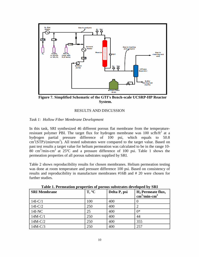
ratios in the ~0.5-3.0 range for chlorides and ammonia removal. The bench-scale unit
seen in Figure 7 consists of a down-flow co-current reactor packed with a 3 ft-long
section of SMVTM
static mixer and is placed in an oven to maintain an inlet reactor
temperature above 245 °F. This prevents sulfur condensation and plugging. Four mass
flow controllers deliver nitrogen, sulfur dioxide, carbon dioxide and hydrogen sulfide
gases respectively. A 4-in.-diameter three-phase tank separated gas and liquids, including
sulfur, after the gas exits the reactor. A solvent pump was used to re-circulate different
solvents. A 9 kW Chromalox® heater maintained the re-circulating solvent at the desired
process temperature.
10
Figure 7. Simplified Schematic of the GTI’s Bench-scale UCSRP-HP Reactor
System.
RESULTS AND DISCUSSION
Task 1: Hollow Fiber Membrane Development
In this task, SRI synthesized 46 different porous flat membrane from the temperature-
resistant polymer PBI. The target flux for hydrogen membrane was 100 scfh/ft2 at a
hydrogen partial pressure difference of 100 psi, which equals to 50.8
cm3(STP)/(min•cm
2). All tested substrates were compared to the target value. Based on
past test results a target value for helium permeation was calculated to be in the range 10-
80 cm3/min-cm
2 at 25ºC and a pressure difference of 100 psi. Table 1 shows the
permeation properties of all porous substrates supplied by SRI.
Table 2 shows reproducibility results for chosen membranes. Helium permeation testing
was done at room temperature and pressure difference 100 psi. Based on consistency of
results and reproducibility in manufacture membranes #16B and # 20 were chosen for
further studies.
Table 1. Permeation properties of porous substrates developed by SRI
SRI Membrane T, ºC Delta P, psi H2 Permeate flux,
cm3/min-cm
2
14I-C/1 100 400 0
14I-C/2 250 400 2
14I-NC 25 400 0*
14M-C/1 250 400 44
14M-C/2 250 400 355
14M-C/3 250 400 257

11
14M-C/4 250 100 8
14M-NC 250 80 378
32014-I 25 400 0*
32014-MD 250 100 42
32015-I/1 25 110 0*
32015-I/2 25 110 0*
32015-I2/1 16 400 0*
32015-I2/2 16 400 0*
32015-I3/1 16 400 0*
32015-I3/2 16 400 0*
32015-MD 250 100 39
7A/1 25 10 194*
7A/2 25 10 194*
7B 250 100 59
7B after 15 hours at 250ºC in He 250 100 38
9A 25 400 0*
9B 25 400 8*
9C 25 400 0*
9D 25 400 15*
9E 250 100 51
9E after 15 hours at 250ºC in He 250 100 42
9F 250 100 78
9F after 22 hours at 250ºC in He 250 100 60
SB-5A 25 400 0*
SB-6A 25 300 0*
SB-7A 25 100 13*
SB-8A 25 400 0*
SB-9A 25 400 0*
SB-10A 25 400 0*
SB-11A 25 400 0*
SB-3B 25 400 0*
SB-5B 25 400 0*
SB-6B 25 400 0*
SB-7B 25 100 0*
SB-8B 25 100 0*
SB-9B 25 100 0*
SB-11B/1 25 60 189*
SB-11B/2 25 40 187*
SB-12B 25 100 0*
SB-13B 25 400 9*
SB-14-1B 25 100 9*

12
SB-14-2B 25 400 0*
SB-14-3B 25 400 0*
SB-14-4B 25 400 0*
SB-15B-1B/1 250 100 131
SB-15B-1B/2 25 100 0*
SB-15B-1B/3 250 100 59
SB-15B-1B/3 after 20 hours at
250ºC in helium
250 100 83
SB-15B-2B 25 400 6*
SB-15B-3B 25 400 0*
SB-15B-4B 25 400 0*
SB-16B/1 250 100 122
SB-16B/2 250 100 179
SB-16B/2 after 15 hours at
250ºC in helium
250 100 145
SB-17B 25 100 105*
20/1 16 100 20*
20/2 16 20 197*
20/3 16 100 20*
20/3 250 100 138
*- Helium permeation values. Due to very low helium permeation flux, no test for
hydrogen permeation was done.
Table 2. Manufacture of chosen substrates: 15B-1 and 16B
Reproducibility testing
Membrane Sheet#-
sample#
T, ºC Δ P, psig He Permeate flux,
cm3/min-cm
2
15B 1-1R 15 100 7
15B 1-2R 15 100 0
15B 1-3R 15 100 89
15B 2-1R 15 100 141
15B 2-2R 15 100 60
15B 2-3R 15 30 194
15B 3-1R 15 100 13
15B 3-2R 15 100 108
15B 4-1R 15 100 0
15B 4-2R 15 60 194
15B-LV 1 16 100 11
15B-HV 1-1 16 100 2
15B-HV 2-1 16 100 65
15B-HV 2-2 16 100 7
16B 1-1R 15 30 196

13
16B 1-2R 15 100 169
16B 2-1R 15 30 196
16B 2-2R 15 40 193
16B 3-1R 15 30 196
16B 3-2R 15 40 196
16B 4-1R 15 40 196
16B 4-2R 15 100 45
16B 4-2R 15 100 48
16B 3-2R 15 100 145
16B 3-3R 15 40 193
16B-LV 1 16 50 197
16B-HV 1-1 16 30 197
16B-HV 2-1 16 30 197
16B-1 1 16 20 197
16B-2 1 16 20 197
20-1 1 17 100 15
20-2 1 17 100 7
20-R 1 17 100 10
20-R 1 250 100 194
20-R 2 20 100 10
20-R 2 250 100 182
Task 2: Synthesis of Hydrogen Selective Membranes
Due to possible thermal stress that may occur during sputtering process, two substrates of
each sample #16 and #20 were thermally treated before metal deposition. The samples
were placed between glass sheets and heated to 250ºC in air for 10 hours. Then four
substrates, two of the originally fabricated and two thermally treated samples were sent to
Intlvac company for metal deposition. The substrates were mounted on a thermally
conductive gasket material and supported by a chrome plated copper plate after pre-
cleaning with Argon ions. A three-layer metal consisting of Pd, Ni-V, and Pd was then
deposited on the PBI substrate. The reaction chamber was slowly vented to atmospheric
pressure using dry nitrogen upon completion of the coating. Post run profilometry
measurements was used to determine actual thickness of metal layers. Overall metal
adhesion to the substrate was good. After frame removal, due to stress of support and
deposited metal, the substrates as shown on Figure 8 became curled and integrity of
supports was destroyed.

14
20-TU-1 16-TT-1
20-TT-1 16-TU-1
Figure 8: Membranes after sputtering
After sputtering process, membranes were subjected to heating at 125ºC for 2 hours to
reduce tensile and compressive stress and uncurl samples. Membranes after the treatment
were essentially free of stress and were tested for helium and hydrogen permeation.
Task 3: Testing of Hybrid Alloy/Polymer Membrane
Membranes synthesized from two sheets of #16: thermally treated before sputtering (16-
TT-1) and thermally untreated (16-TU-1) and two of # 20 samples: thermally treated
before sputtering (20-TT-1) and thermally untreated (20-TU-1) were tested for gas
permeation. Permeation flux data for helium and hydrogen are shown in Table 3. All four
membranes show similar high permeation flux values and no hydrogen selectivity is
observed. Based on results, it can be concluded that metal layers deposited on support are
not dense, and there are still open pores, which allow gases permeate through the
membrane.

15
Table 3. Permeation properties of synthesized membranes.
Membrane Thickness of
Pd-V/Ni-Pd
layers, µm
Thermal
treatment
Ion assist during
sputtering process
H2 /He flux*,
mol/cm2-min
16-TT-1 1-3-1 + - 419/4321
16-TU-1 1-3-1 - - 417/4321
20-TT-1 1-3-1 + - 406/4082
20-TU-1 1-3-1 - - 419/4192
16-with i/s 0.5-1-0.5 - + 0/0
16-without i/s 0.5-2-0.5 - - 0/0
20- with i/s 0.5-1-0.5 - + 0/0
20-without i/s 0.5-2-0.5 - - 0/0
16/1 0.1-3-0.1 - + 0/03
16/2 0.05-3-0.05 - + 0/03
20/1 0.1-2-0.1 - + 0/03
20/2 0.0.5-2-0.05 - + 0/03
Due to no difference in permeation fluxes of membranes deposited on thermally treated
and thermally untreated supports and their similar stability, no thermal treatment was
carried out before sputtering procedure.
Based on the permeation results of first four synthesized membranes, parameters for
sputtering process were changed to deposit additional dense metal coating on substrates.
An ion source was used for membrane synthesis to produce complete dense films (to
have all pores closed by metal layers). Four membranes were synthesized using
membranes: two sheets of #16 (with and without ion source) and two of # 20 samples
(with and without ion source). Thickness of layers in case of ion source assistance is
0.5µm Pd, 1µm Ni-V, and 0.5µm Pd. Two other membranes have the same thickness for
Pd layer, but 2 µm Ni-V layer. Permeation flux data for helium and hydrogen are shown
in Table 3. All four membranes show no helium and hydrogen fluxes at 250ºC and
pressure difference 200 psi. Based on literature palladium has lower permeability at these
conditions than V-Ni layer, therefore Pd layer thickness was reduced from 0.5 microns to
0.1 and 0.05 microns keeping thickness of V-Ni layer the same. The synthesized
membranes (16/1, 16/2, 20/1, 20/2) showed no hydrogen or helium permeability. Higher
feed pressure and higher temperature did not affect the performance.
To understand why membranes were not permeable, energy-dispersive X-ray
spectroscopy was used to determine the chemical composition of the metal layer,
specifically to identify metal oxides. An SEM image of the membrane is shown in Figure

16
9. EDS measurements were taken at points shown on the image labeled “Spectrum x”.
The EDS measurements give the chemical composition at a specific point, with a radius
of 1 µm. The concentrations at the points measured are shown in Table 4. Results
showed the presence of oxygen in some places where vanadium was detected, indicating
that the vanadium is in an oxide form. Where both vanadium and oxygen were detected,
the O/V ratio was 1.2. There was no oxygen detected in the palladium layer. The
vanadium oxide layer was impermeable to any gas tested and is considered to have a zero
permeation flux.
\
Figure 9: SEM image of synthesized membrane.
Table 4. Composition of metal layer at various points (shown in Figure 1). Values
given in weight percent.
Thermal stability of the polymer membrane layer (without metal) was tested under a flow
of helium and at different temperatures. Permeability as a function of temperature and
time is shown in Figure 10. As the temperature increased, the permeability decreased and
permeation dropped to 90 mL/min at 350oC. As the membrane was held at that
temperature the permeation decreased to 44 mL/min after 33 minutes at 350oC (pressure
on the retentate side was constant). This is likely due to expansion of the polymer as it is
heated, which blocks the micro pores in the membrane. It was determined that due to a
thermal instability of porous network in membranes, these porous supports cannot be
used for hydrogen separation at higher temperatures and extended periods of operations.
Pd V O Ni Al
Spectrum 1 99 1
Spectrum 2 12 78 9
Spectrum 3 37 45 9 8
Spectrum 4 36 44 11 9
Spectrum 5 90 9
Polymer
Metal

17
Figure 10: Impact of temperature and time on permeability of polymer membrane
(without metal layer).
Task 4: Testing UCSRP-HP for Low-level Sulfur Removal
In this task H2S removal testing was done to simulate the 1st stage of the 2 stage reactor
system for sulfur removal using UCSRP-HP. Results indicated that with an inlet H2S
concentration of ~6000 ppmv, the outlet gas stream from the 1st stage reactor could be
reduced to ~40-500 ppmv. Using Design of Experiments (DoE) the test plan within the
parameters specified in the project objectives was derived and executed to give the results
shown in Table 5.
Table 5. Test Plane for Low Inlet H2S Removal
Pressure,
psig
Gas
flow,
scfh
Liquid
flow,
Lpm
Temp,
°F
Inlet
H2S,
ppmv
Inlet
SO2,
ppmv
Excess
H2S, %
100 - - 250 80 38 5
100 - + 250 80 38 5
100 c - 250 80 38 5
100 c + 250 80 38 5
400 + - 250 80 38 5
400 + + 250 80 38 5
400 ++ - 250 80 38 5
400 ++ + 250 80 38 5
The results in Table 6 show that more than 95%+ conversion of H2S even with such low
inlet H2S concentrations resulting in less than 4 ppmv H2S in the 2nd
Stage outlet gas

18
stream.
Table 6. Low-Level Sulfur UCSRP-HP Results
Exp
# Pressure
psig inlet [H
2S]
ppmv Inlet [SO
2]
ppmv Outlet [H
2S]
ppmv Outlet [SO
2]
ppmv H
2S
conv. % 1 399 73.0 33.0 2.3 2.5 96.9 2 401 73.0 33.0 1.3 9.5 98.3 3 397 80.6 37.8 3.2 5.0 96.0 4 398 80.6 37.8 1.8 3.3 97.7 5 100 83.7 39.5 1.8 2.1 97.9 6 102 83.7 39.5 3.3 5.6 96.0 7 101 81.3 38.7 2.8 3.4 96.6 8 100 80.0 38.0 3.7 3.0 95.4 9 101 80.0 38.0 2.4 2.5 97.0
Task 5: Testing UCSRP-HP for Trace Component Removal
The purpose of the task was to identify a solvent for use among DEG, DGM and water
can for NH3 and HCl removal using the same down-flow, co-current reactor with SMV
packing used for sulfur tests described in Task 4. Table 7 shows that at high superficial
velocity (2 ft/s), HCl removal less than 80% when water is used as a solvent. When a
superficial gas velocity was decreased to 1 ft/s but with the same water flowrate, target
value for HCl removal (80%) was achieved. Hence, remained experiments were done at
superficial gas velocity equal 1 ft/s. Test # 3 was done to show reproducibility of
experimental work.
Table 7. Testing UCSRP-HP for Trace Component Removal (HCl)
Exp
#
Pressure
psig
gas
flow
scfh
Superficial
gas velocity
ft/s
Solvent
Type
L/G
mass
ratio
inlet
[HCl]
ppmv
Outlet
[HCl]
ppmv
HCl
removed
%
1 399 790 2 water 3.3 35.3 10.8 69.4
2 401 355 1 water 7.3 36.1 0.04 99.9
3 397 356 1 water 7.3 38.8 0.08 99.8
4 398 355 1 water 2.4 38.8 0.9 97.7
5 401 359 1 DEG 7.9 43.3 0.04 99.9
6 405 360 1 DEG 2.6 41.8 0.12 99.7
7 400 358 1 DGM 2.4 42.1 0.11 99.6
8 403 355 1 DGM 7.3 43.9 0.02 99.9

19
Solvents as DEG and DGM show high degrees of HCl removal at the same conditions.
Table 7 demonstrate that all three solvents can be used efficiently for HCl removal
(>97%) at superficial gas velocity of 1 ft/s.
Table 8. Testing UCSRP-HP for Trace Component Removal (HCl)
Exp
#
Pressure
psig
gas
flow
scfh
Superficial
gas velocity
ft/s
Solvent
Type
L/G
mass
ratio
inlet
[NH3]
ppmv
Outlet
[NH3]
ppmv
NH3
remov
ed %
9 400 360 1 DGM 7.7 38.5 20.4 47.0
10 405 355 1 DGM 7.8 25.3 11.1 56
11 407 360 1 DGM 2.6 25.7 18.2 29
12 401 351 1 DEG 7.9 26.5 6.9 74.0
13 400 351 1 DEG 2.6 27.5 10.5 61.8
14 403 351 1 Water 7.9 26.0 3.2 87.7
15 399 352 1 Water 2.6 27.8 2.9 89.6
For NH3 removal testing a superficial gas velocity of 1 ft/s, liquid flow rates and inlet
NH3 concentration were maintained at the same conditions as in HCl removal
experiments (see Table 8). Due to low degree of NH3 removal shown in experiment 9,
inlet NH3 concentration was reduced (experiments 10-13) which leads to higher value of
the removal efficiency, but lower than target value. Experiments 15, 16 show water
performance as a solvent and demonstrate that water is best solvent for NH3 removal.
Based on the results in Tables 7 and 8, it is clear that water is the best performing solvent
when either HCL or NH3 are treated. However, since syngas derived from Coal contains
both components as well as other contaminants, it is reasonable to assume that both HCl
and NH3 will be removed efficiently with all three solvents due to reaction between
components as shown in the following reaction: NH3(g) + HCl(g) = NH4Cl(aq).
Task 6: Economic Evaluations
Liquid production case:
DOE/NETL has published data for technical and economic feasibility of a small-scale
coal-to-liquids (CTL) facility (nominal 10,000 BSD of liquids) in southwestern West
Virginia1. The facility employs gasification and Fischer-Tropsch (FT) technology to
produce commercial-grade zero-sulfur diesel and naphtha from a high-sulfur bituminous
coal. For the design estimates, coal/water slurry-fed GE gasifiers were used to gasify
~3,628 metric tons/day of dry Pittsburgh No. 8 coal (containing ~2.9% sulfur, as-received
coal basis) to produce syngas for the production of ~9,609 BSD of diesel + naphtha (~56
vol. % diesel). H2/CO molar ratio of the syngas from a scrubber unit (used to treat the
gasifier effluent) was estimated at ~0.80. Following additional clean-up for the removal
of various contaminants (including H2S), the syngas feed to the FT plant contained a
H2/CO ratio of ~0.81. A schematic of the overall flow-sheet of the gasification/FT
concept is shown in Figure 11.

20
Figure 11: Overall Flow-sheet for the production of Diesel plus Naphtha from Coal
Syngas generated from AR coal gasification has a H2/CO ratio of about 0.4. A natural gas
(NG) partial oxidation process (with some CO2 recycle) was used in addition to the coal
gasification to generate a specific syngas composition, so that the fresh mixed syngas
(from coal + NG) feed to the FT reactor has the same composition as in DOE Case1 for
accurate comparison.
Figure 12: Schematic of the Coal plus NG Design Case used in this TEA
The coal and NG hybrid feed concept is shown in Figure 12. Material balances for the
coal gasifier were provided by AR; those for the POX reactor were estimated in-house by
via Aspen Plus software. The operating conditions of the POX reactor were selected to
match the flowrate as well composition of the syngas feed (Stream # 10 in Figure 12) to
the FT reactor. The pressure and temperature at the POX reactor outlet are 800 psia and
2400 °F respectively. From the CO2 recovery unit (located in the FT unit), certain amount
(~32% of the NG feed, volume basis) of pure CO2 is recycled to the POX reactor to

21
match the flowrate and composition of the fresh syngas feed to the FT reactor. The cost
estimates include: (1) ~ 91% capture of the feed carbon in coal plus NG, and (2)
compression of CO2 to ~2,200 psia. For the economic comparisons, it was assumed that
(1) the annual capital-related expenses are 13% of the total CAPEX (which reflects ~12%
ROI), and (2) annual OPEX-related expenses to be 9% of total CAPEX.
As shown in Table 9:
The Coal/NG option could reduce the cost of breakeven Brent Crude Price (BCP,
at ~12% ROI) by about 30% (based on a coal cost of $1.70/Million Btu and
$4.00/MMBtu for natural gas); $45/bl for the coal/NG options vs. $63 for the coal
only option. If 20 cents/gal credit is considered for the zero-sulfur FT products,
the BCP would be reduced to ~$38/bbl and $56/bbl respectively. Key details are
given in Table A-1.The total CAPEX for the coal/NG option would be ~29% less
than that projected by DOE for the coal-only case.
In the Coal + NG case, ~86 MW of electric power is exported (vs. ~33 MW for
the coal only case).
Table 9. Comparative Data for Required Selling Prices of FT Liquids at the Plant
Gate (2013 $)
Design case Coal plus NG Feed
in Two Reactors
DOE 9,609 BSD Data :
Coal Gasification
Total CAPEX, $MM (2013$) 659 928
Coal feed rate, Dry, kg/hr 77,528 151,147
NG feed rate, Kg/hr 40,889 --
Oxygen need, Metric tons/day 3,313 3,565
Annual Cost of Coal, $MM/yr.
($1.70/MMBtu)
29.12 56.77
Annual Cost of NG
(@$4.00/MMbtu), $MM/yr
60.93 --
Annual CAPEX/OPEX related
Costs, $MM/yr. (22% of CAPEX),
$MM/yr.
144.98 204.16
Export of Electricity, MW
Credit (@10 cents/kwhr), $MM/yr
85.914
67.74
33.204
26.18
Total Credits, $MM/yr 94.26 52.7
Net Costs, $MM/yr. 140.77 208.23
Required Selling Price (RSP) at the
Plant Gate, $/bbl
53.0 74.4
Breakeven Crude Price (BCP; RSP
x 0.84), $/bbl
44.5 62.5
BCP with a 20 cents/gal credit for
the zero-sulfur FT products, $/bbl
37.5 55.4

22
IGCC case:
A schematic of the overall flowsheet of the PWR power production plant is shown in
Figure 13. Consuming 444,737 lb/hr of Illinois No. 6 coal (as received), the PWR power
production plant produces a net 555.7 MWe for an overall thermal efficiency (HHV) of
32.7%. The Total Plant Cost is estimated to be $1,389,000,000 (2013$). At a 90%
capacity factor, the Levelized Cost of Power is $111/MWh.
Figure 13: PWR Power Production Plant Block Flow Diagram
For the integrated process design estimate, the combined coal and natural gas syngas was
treated in the water gas shift system, gas cooling, boiler feed water, and knockout unit
blocks. Sulfur removal and recovery, as well as removal of trace components such as
arsenics, chlorides, and mercury, was performed using GTI’s UCSRP process. Hydrogen
separation was done using GTI’s hydrogen membrane system and the CO2-rich gas (CO2
>95% by volume) is compressed to ~2,200 psia for further sequestration. The steam
produced by the POX energy recovery generates 30 MWe for use in the plant. The plant
produces a net of 552 MWe for an overall thermal efficiency of 32.7%. The Total Plant
Cost is estimated to be $1,177,000,000. At a 90% capacity factor, the Levelized Cost of
Power is $82/MWh- see Figure 15.

23
Figure 14: GTI Power Production Plant Block Flow Diagram
Table 10 shows the key differences in the cases studied in this report.
Table 10 Case Summary
DOE: IGCC/GEE/
Selexol
GTI Case 2: IGCC,
GEE/UCSRP
GTI Case 4: IGCC,
AR/UCSRP
Feed, lb/hr
Coal 5838 5838 3171
NG 0 0 2891
Coal gasifier GEE GEE AR
NG gasifier
POX
Gas Clean-up Selexol UCSRP UCSRP
Power Output,
MW 556 560 581
The coal plus natural gas feed case shows improved cost of electric production at all
historical levels of natural gas prices.

24
Figure 15: Levelized Cost of Electricity
From the economic analyses, the coal plus natural gas case results in slightly lower
electric cost than the coal only case. Reduction in the capital costs for solids processing,
gas clean-up, and gasification (POX of a gas stream instead of coal gasification) more
than offsets the higher feed cost ($4/MMBtu for natural gas versus $1.70/MMBtu for
coal).
Hydrogen production:
This case addresses the production of high-purity hydrogen, via the integration of an AR
coal gasifier and a natural gas partial oxidation reactor along with GTI’s integrated,
multi-contaminant removal process and the hydrogen membrane process. Published data
from DOE/NETL for IGCC and hydrogen production [DOE/NETL-401/062006] was
used as a basis of this comparison. This report compared the AR compact gasifier with
the GEE gasifier in hydrogen production and carbon capture mode [DOE/NETL-
2010/1397].
Co
st o
f P
ow
er,
$/M
WH
Natural Gas Price, $/MMBtu
Operating Costs
NG
Coal
Capital Cost
DOE Case 2

25
Figure 16: PWR H2 Production Plant Block Flow Diagram
A schematic of the overall flowsheet of the AR H2 production plant is shown in Figure
16. Consuming 419,050 lb/hr of Illinois No. 6 coal (as received), the PWR hydrogen
production plant produces 56,179 lb/hr of 99.99%+ H2. The plant requires the import of
31 MWe of power from another source to meet a total auxiliary load of 117 MWe. Total
Plant Capital cost is estimated to be $640,480,000. At a 90% capacity factor, the
Levelized Cost of Hydrogen is $1,027/Ton or $1.03/kg [DOE/NETL-401/062006].

26
Coal Dryer
ASUWater-Gas
Shift Reactor
Gas Cooling,
BFW Heating
Sour Water
Scrubber
UCSRP-HP
Guard Bed
Hydrogen
Membrane
CO2
Compressor
Power Gen
HRSG
AR Gasifier
Quench Scrubber
Nitrogen
Air
HP CO2
Hydrogen Product
Waste Water
Sulfur Dioxide
Sulfur
Stream
POX
Stream
Natural Gas
Oxygen
Oxygen Stream
Coal
Air
Stack Gas
To Coal Transport
1
2 3
4
5
6
75
8
9 10
11 12
13
14 15
16
17
18
19
Figure 17: GTI H2 Production Plant Block Flow Diagram
Table 11 Key Comparative Data

27
Notes:
PWR Case1: Case 5 hydrogen production in PWR study (DOE/NETL-401/062006)
PWR Case2: Adjustment made to Case 5 hydrogen production in PWR study
GTI Case 1: GTI H2 product plant using combined coal and natural gas, without the
import of electricity
GTI Case 2: GTI H2 product plant using combined coal and natural gas, with the import
of electricity
GTI Case 3: GTI H2 product plant using coal, with the import of electricity
Table 11 shows the key comparative data. A higher cost for natural gas drives the
operating costs up, resulting in the same levelized cost of hydrogen compared to AR case
2. Meanwhile, GTI case 1 has much lower capital investment (~$116 MM less), due to
GTI’s UCSRP system and hydrogen membrane system. It also produces more hydrogen
(14,183 TPY more) and is environmental-friendly (856,770 TPY CO2 less) when
combined fuel (natural gas and coal) are used. To demonstrate the benefits GTI case
offers, a case study was performed in which only coal (Illinois No. 6)was selected as fuel
for hydrogen production. When compared at the same plant size (equivalent to 550 MWe
power plant), GTI case 3 offers less capital cost (~$38 MM less) but also greatly reduces
the levelized cost of hydrogen (~6% less) than that of AR case 2.
CONCLUSIONS AND RECOMMENDATIONS
Design Case PWR Case 1 PWR Case 2 GTI Case 1 GTI Case 2 GTI Case 3
Plant size (MWe power plant) 440 550 550 550 550
Coal feed rate (as received), lb/hr 419,050 489,610 241,950 241,950 489,610
Natural gas feed rate, lb/hr 0 0 127,920 127,920 0
% energy from feed coal 100 100 51 51 100
O2 needed, TPD 3,600 4,206 4,127 4,127 4,206
H2 (99.99%+) product, lb/hr 56,179 65,638 69,604 70,180 65,638
CO2 generated, lb/hr 979,529 1,144,463 904,882 904,882 1,144,463
Steam generation power, MWe 86 100 112 112 100
Total auxiliary load, MWe 116 135 118 118 123
Import of electricity, MWe 31 36 0 6 23
Total plant capital cost, $ 640,480,000 712,683,000 596,648,000 587,531,000 674,480,000
Levelized cost of hydrogen, $/TON 1,027 1,005 1,001 1,000 944
Levelized cost of hydrogen, $/kg 1.03 1.01 1.00 1.00 0.94

28
Conclusions reached in this project are:
Achieved >90% H2S conversion with outlet H2S concentration of less than 4
ppmv through the UCSRP process and 80-90% ammonia and chloride removal
Using overall energy input of 53% coal and 47% natural gas to a plant producing
~9,609 BSD of diesel and naphtha at ~56 vol. % diesel with the UCSRP-HP
process for sulfur removal, the GTI Case could reduce the cost of breakeven Brent
Crude Price (BCP) by about 30%. The total CAPEX would be reduced by ~29%
as compared with DOE Case reported in DOE/NETL Report # 2007/1253.
For chemical-grade hydrogen production with carbon capture case, the GTI
process showed a 10% reduction in the price of H2 resulting in a $21,000,000
saving per year.
For IGCC plant with carbon capture case, the GTI process showed savings in
CAPEX and OPEX resulting in a reduction in LCOE.
PBI supports synthesized during this project are acceptable for hydrogen selective
membranes.
Metal/polymer composite membranes were successfully synthesized using
sputtering process
Synthesized membranes show complete impermeability due to vanadium oxide
layer formation when the membrane was exposed to air.
For further scale up of the UCSRP-HP process, the following experimental programs
are recommended:
Conduct pilot scale testing at gas flow rate up to 1 MMSCFD.
Use a down-flow co-current reactor, fitted with SMV packing, with a larger
internal diameter to study various reactor scale-up parameters.
Extend the operating pressures to ~800-1000 psig.
Explore, if other solvents, e.g., the Uhde/GTI Morphysorb® or dimethylether of
polyethylene glycol (generic Selexol), can be used as the solvent in the UCSRP-
HP process. If confirmed, this would avoid process complications related to
mixing of DGM solvent with that used in the downstream CO2-removal step.
Explore other support materials for H2 development.
Explore different metals/alloys, such Nb, Ta etc.
Explore other deposition methods.
REFERENCES

29
1. DOE/NETL Report # 2007/1253, “Technical & Economic Assessment of Small-
Scale Fischer Tropsch Liquids Facilities”, Feb. 27, 2007
2. DOE/NETL-401/062006, Comparison of Pratt and Whitney Rocketdyne IGCC
and Commercial IGCC Performance, final report, June 2006.
3. DOE/NETL-2010/1397, Cost and Performance Baseline for Fossil Energy Plants,
volume 1: Bituminous Coal and Natural Gas to Electricity, revision 2a, September
2013
4. GTI report 20251, Evaluation of UCSRP-HP for the Production of Power, Clean
Fuels & Chemicals Using Coal Gasification, September 2010.
DISCLAIMER STATEMENT

30
This report was prepared by Razima Souleimanova, Gas Technology Institute, with
support, in part, by grants made possible by the Illinois Department of Commerce and
Economic Opportunity through the Office of Coal Development and the Illinois Clean
Coal Institute. Neither Razima Souleimanova & Gas Technology Institute, nor any of its
subcontractors, nor the Illinois Department of Commerce and Economic Opportunity,
Office of Coal Development, the Illinois Clean Coal Institute, nor any person acting on
behalf of either:
(A) Makes any warranty of representation, express or implied, with respect to the
accuracy, completeness, or usefulness of the information contained in this report,
or that the use of any information, apparatus, method, or process disclosed in this
report may not infringe privately-owned rights; or
(B) Assumes any liabilities with respect to the use of, or for damages resulting from
the use of, any information, apparatus, method or process disclosed in this report.
Reference herein to any specific commercial product, process, or service by trade name,
trademark, manufacturer, or otherwise, does not necessarily constitute or imply its
endorsement, recommendation, or favoring; nor do the views and opinions of authors
expressed herein necessarily state or reflect those of the Illinois Department of
Commerce and Economic Opportunity, Office of Coal Development, or the Illinois Clean
Coal Institute.
Notice to Journalists and Publishers: If you borrow information from any part of this
report, you must include a statement about the state of Illinois' support of the project.