low cost marine black box design
TRANSCRIPT

Low Cost Marine Black Box Design
Department of Electrical and Electronic Engineering
A Thesis
Submitted to the Department of Electrical and Electronics Engineering
Of
BRAC University
By
Imtiaz Kalam Abir (12121037)
Rumana Rafique (12121022)
Sibaji Roy (10121001)
Supervised by
Dr. Md. Khalilur Rhaman
Associate Professor
Department of Computer Science and Engineering
BRAC University, Dhaka

1 | P a g e
Declaration
We do here by declare that the thesis titled ‘Low Cost Marine Black Box’ is submitted to the Department
of Electrical and Electronic Engineering of BRAC University in partial fulfillment of the Bachelor of
Science in Electrical and Electronics Engineering. This is our original work and was not submitted
elsewhere for the award of any other degree or any other publication.
Date: 20.08.2015
__________________________________
Authors Dr. Md. Khalilur Rhaman
Thesis Supervisor
Associate Professor
Department of Computer Science and Engineering _____________________________________
BRAC University Imtiaz Kalam Abir (12121037)
______________________________________
Rumana Rafique (12121022)
__________________________________
Sibaji Roy (10121001)

2 | P a g e
Acknowledgement
We would like to take this opportunity to express our gratitude to Dr. Md. Khalilur Rhaman for his
guidance, and instruction that he has given us from the time we have been doing the thesis project ‘Low
Cost Marine Black Box’ under his supervision through the completion of our undergraduate program. The
skills we have able to learn from him during our Thesis work have benefited us immensely and will continue
to do so throughout our future endeavors. We also want to show our appreciation towards our mechanical
helper Mr. Mohammad Munir for his huge exertion in building the vital structures that were utilized for
drawing out this venture towards achievement.

3 | P a g e
Abstract
One of the most recurring and uprising problem in our country is marine accidents. Due to this
catastrophe thousands of people loses their lives every now and then. The major reasons behind
this problem are overloaded passengers boarding the ship and weather conditions along the river
route. One solution to this problem would be monitoring the marine vessels and keep a track of
the routes that it traverses. Therefore, we are keen to design and implement an economical black
box which will be highly efficient and effective in the marine sector of our country. To minimize
the marine accidents occurring in our country, we have come up with this noble idea. The main
features of this box include measuring weather, keep account of the total number of passengers
boarding, track the location of the ship, save data in SD card for record and send necessary data to
web database. To perform these operations, the system is loaded with GPS tracking device, GSM-
GPRS device, temperature, pressure and humidity sensors, water level sensors, passenger counter
and background web server. Most importantly it will be made in such a way that it remains water
proof and floats on water making it functional enough to send emergency signals during
catastrophe. In order to throw the black box in the water during emergency, a well-designed trigger
unit will be used. Moreover, an Android based Application would be built that could show the map
of ship’s present location and necessary data of any given time fetching it from the web database.

4 | P a g e
Table of Contents
TOPIC PAGE NO
CHAPTER: 1 INTRODUCTION_____ __________ ___________________ _6-15
1.1 Objective _6 1.2 Scenario in Bangladesh 7 1.3 Motivation 9 1.4 Literature Review 11
CHAPTER: 2 SYSTEM OVERVIEW__________ ______________________16 - 22
2.1 General overview of the System__ 17 2.2 Black Box 18 2.3 On Board Processor_ 19 2.3.1 Weather Station 19 2.3.2 Passenger Counter 20 2.4 Trigger Unit 21 2.5 Web Database and Android Application 22
CHAPTER: 3 SYSTEM IMPLEMENTATION_____ _________________ 23 -55
3.1 Black Box Design ______________________________________________________ 23 3.1.1 Hardware 23 3.1.2 Circuit 26 3.1.3 Control 27 3.1.4 Communication_______________________________________________________ 28 3.1.5 Power 29
3.2 Onboard Processor__________________________________________________ _ 30 3.2.1 Weather Station 30
3.2.1.1 Circuit 31 3.2.1.2 Control__________________________________________________ 32 3.2.1.3 Communication 33 3.2.1.4 Power 33
3.2.2 Passenger Counter 34
3.2.2.1 Hardware 34 3.2.2.2 Circuit 35 3.2.2.3 Control_ 36 3.2.2.4 Communication 37 3.2.2.5 Power 37

5 | P a g e
3.3 Trigger Unit_________________________________________________________ 38 3.3.1 Water Level Sensor______________________________________________ 38 3.3.2 Motor Driver___________________________________________________ 39 3.3.3 Actuator_______________________________________________________ 39 3.3.4 Thrower Cannon/Trigger___________________________________________
40 3.3.5 Output___________________________________________________ 42 3.3.6 Control________________________________________________________ 42 3.3.7 Power______________________________________________________ ____42 3.3.8 Circuit________________________________________________________ 43
3.4 Software____________________________________________________________ 44 3.4.1 Web Database__________________________________________________ 45 3.4.2 Android Application_______________________________________________ 48
CHAPTER: 4 DATA ANALYSIS______ ______________________________56 - 63
4.1 On Board Processor Analysis____________________________________________ 56 4.1.1 Weather Data Analysis__________________________________________________ 55 4.1.2 Passenger Counter Analysis_______________________________________________56
4.2 Trigger Unit Efficiency Analysis________________________________________________ 58 4.3 GPS Data Accuracy__________________________________________________________ 59 4.4 Application Response Time vs. Internet Speed____________________________________ 61 4.5 Compatibility to various Android API___________________________________________ 62
CHAPTER: 5 DISCUSSION ______ _________________64 – 68
CHAPTER: 6 REFERENCE_____________________ _________________69 - 70
CHAPTER: 7 APPENDIX_______________________ _________________ 71 -85

6 | P a g e
Chapter - 1
Introduction
1.1 Objective The ‘Low Cost Marine Black Box’s main objective is to locate and investigate the basic and more
primary reasons of the unfortunate marine accidents. In most of the cases we see that the reason
gets into undercover because of the low quality equipment used in the water vessel. Moreover
ultimately in most of the cases the victim vehicle is not at all located and found out. Our objective
is to make a system by which we can estimate and at most cases take an idea of the main reason to
the specific accident which can indeed be a very important way to resolve the issue and make the
accident rate low in some ways. Or again in the most cases the Black Box can locate the affected
vehicle and amount of damage done to it due to the accident.
Another objective is to make an awareness to the Water Vessel owners and drivers about the
difficulties, weather turbulences in some particular area and routes where they can avoid the route
in some critical weather forecasts. It can also be very helpful to make the accident issue
understandable to the major part of Water vessel driver and associates who are not so technically
sound. We found out in our studies that during turbulent weather conditions drastic change happens
to the Temperature, Pressure and Humidity in the specific area or route. Using the readings of past
accident scenarios the driver and associates can be trained in a good way to let them learn the exact
technics of getting rid of those turbulent and possibly dangerous conditions and situations.
In the most of the cases of accidents now a days it is very difficult to identify the exact number of
passengers who are actually affected by the accident. Moreover in maximum cases the accidents
occur due to excessively crowded water vessels. Such as PINAK-6 had actually more than 5 times
more passengers than the launch could hold. But no proof was there and the persons who were
guilty for this could not be punished due to lack of technology there. Even many dead bodies of
the victim could not be found due to excessive current through Padma River. By including an
element called Passenger Counter our Black box can give the precise number of travelers who
were boarded and even under the least favorable conditions conceivable situation it can mindful

7 | P a g e
the travelers to not to board in a water vessel which is packed. It is additionally one of the
fundamental targets of our Low cost marine black box. Another target is to seek what and how
adaption activities ought to be considered in water transport framework arranging, venture
advancement, operations and upkeep and what are the variables and specialized prerequisites to
bolster doable and powerful keeping up and overseeing marine transportation.
1.2 Scenario in Bangladesh:
Bangladesh is a riverine nation and conduits are essential method for correspondence in this
district. Since quite a while, waterway system has been viewed as protected and financially savvy
course particularly in the southern piece of Bangladesh. Consistently through this course
(Bangladesh Inland Water Transport Authority) bears 87.80 million travelers. This vital method
of transport is ridden with shocking catastrophes consistently, causing a substantial toll of human
lives. Around 3,869 individuals have passed on and 279 turned up lost in 458 dispatch fiascos
since 1976 (Department of Shipping). The inland courses of Barisal, Bhola, Chandpur and
Patuakhali and their joined conduits to Dhaka and Chittagong are observed to be clumsier.
Limitless operation of unfit vessels, over-burdening of traveler, enrollment of untalented groups,
poor limit of important government authorities and low standard support of Inland Water Transport
(IWT) channels are starting these lethal mishaps. [1]
According to a report May 2014, At least 4,420 people died, 520 people injured and 400 people
remained missing in more than 550 passenger launch accidents that took place in last 38 years,
including latest launch capsize in Ramnabad River in Golachipa under Patuakhali. Of those,
around 1,960 persons died and 176 persons went missing in the last decade, according to the
official statement of the Department of Shipping and Bangladesh Inland Water Transport
Authority (BIWTA). However, experts claim the actual number of accidents, death and missing
was higher than shown in the government statistics. According to the experts and officials
concerned, gross negligence of the authorities in ensuring safety measures, awarding licenses
coupled with a lack of awareness among passengers and plying the launches with inefficient
masters (drivers) caused most of these accidents and also for the stormy condition in that particular
route. [2]

8 | P a g e
Vessels Operating in Inland Waterways of Bangladesh:
There are a few sorts of inland water transports working all through the nation. For
straightforwardness, these are considered under seven distinct classifications as takes after:
Payload Ships , Traveler Launches, Traveler Trawlers , Traveler steamers , Payload Trawlers ,
Ships , Motor Boats , Nation Boats and Others.
Payload boats are fundamentally bigger vehicles which are made of steel body and frequently
planned with sub-divisional bulkheads to give water snugness to the freight holds. Likewise,
payload boats contain freight hatch openings on the upper deck through which the items are being
stacked and emptied. Additionally some freight boats contain independent pumping offices to
stack or empty fluid cargoes on or off the load opening.
The traveler dispatches are for the most part made of steel structure with no assigned payload
holds. Rather than obvious load compartments, traveler dispatches contain littler private lodges to
give some extravagance and security to the rich travelers. In any case, in the vast majority of the
traveler dispatches there stay extensive open spaces on the decks where the economy class travelers
live scattered amid a voyage. It merits saying that both payload boats and traveler dispatches are
outlined with mechanical or water driven controlling and basically being utilized for medium to
long separation going in Bangladesh.
Traveler trawlers and freight trawlers are both comparative sort of vehicles where the main contrast
lies on what they convey amid their voyages; i.e. on the off chance that they convey travelers amid
a voyage, they are assigned as traveler trawlers and in the event that they convey load, they are
called as payload trawlers. Fundamentally these vehicles are expansive wooden vessels with some
steel plating followed at the external skin furthermore have motors mounted at the backside .Most
of them contain neither payload holds nor traveler lodges aside from a couple encased spaces for
the teams and in this way, these vehicles are utilized for medium to short separation voyaging.
The motor water crafts are likely the most mainstream method of transportations for medium to
short separation voyaging. Such vessels are wooden made and impelled by agrarian multipurpose
motors which are regularly known as shallow motors. These vehicles are moderately littler than
trawlers however discernibly bigger than smaller nation water crafts. No compartments or encased

9 | P a g e
spaces are found in this kind of vessels and in a general sense these vessels have stand out deck to
convey travelers and their items and controls physically utilizing by regional standards made
rudders.
Nation water crafts in Bangladesh are numerous in numbers and changed in sorts with rich
conventions that follow back several years into the past. Be that as it may, the regular trademark
that the majority of the nation vessels have is that every one of them are non-motorized and
physically moved. The vast majority of the nation pontoons have the procurement of being towed
by the wind force utilizing exceptionally conventional looking sails, especially in the inland waters
of the nation. Bangladesh has an extensive variety of marine vehicles numbers and in sorts.
In Bangladesh, marine accidents have become most common topics in the headlines of the
newspapers nowadays. There are various reasons behind these accidents like overload of
passengers, tough weather conditions etc. These accidents occur because of negligent mistakes but
the effects of the same are lasting and lingering. Many people died in our country because of
marine accidents and we have seen that the ship could not be traced as well as dead bodies could
not be found. Recently, the collision between the oil tanker and the cargo vessel occurred at the
Sela River in Sundarbans, Khulna division, Bangladesh. The ship sank and some people died.
Moreover, an oil spill occurred that lead many animals and trees to die. This is not the only
example; there are other incidents too of marine accidents. So we decided to build marine black
box that would be highly efficient in detecting critical consequences of marine accidents and also
this will be cost effective. [1][2]
1.3 Motivation:
An effective and efficient Low cost Marine Black Box is an instrument by which the whole idea
of searching the unfortunate water vessels which have been affected by the naval accidents can be
changed. In Fall 14 we came out with the plan of constructing a low cost device which can be
detected by the rescue teams of the unfortunate victim water vessels. Actually before that the heart
breaking accident of PINAK-6 happened in the route of MAWA – KAWRAKANDI route and
ultimately due to the low management system and the low equipped systems the PINAK-6 launch

10 | P a g e
was not detected and rescued from the river of PADMA. The actual amount of passengers who
died in the accident was not also could be detected. We were really inspired to make a device that
can at least detect the whole causes of accident, total passengers in the vessel, ultimate reason of
the accident etc. With our Marine black box and the features we used it will be pretty much clear
that why such accident could be happened. Really after that we went to a few sites and read about
the real save and examination method of the BIWTA division of the administration who are
basically the power to research such sorts of mischances. In any case, subsequent to experiencing
a few sites and each one of those contents, we were truly baffled watching at the old style of
bringing information and with the utilization of old gear in a large portion of the cases. The
investigations were so back dated that by those things we could understand that why the Marine
accidents are not investigated properly. The only thing that took our attention was the Sonar system
that has brought here from abroad. The interesting and shocking part is that the maintenance of the
station is not so easy, that's why it requires expert technician's to control that. So from that very
moment we came to realize that the system of BLACK BOX which are normally used in Air Crafts,
if these are implemented here in the water vessels at low cost using local technical help, it can be
more easier to find the unfortunate vehicle for the sonar system or our rescue operators or less
expert technicians to make use of this Low Cost Marine Black Box. So thinking for a Low cost
version of Black box which will be cost effective , portable structure ,will have digital data
acquisition system, very easy maintenance system and affordable in the context of the economic
status of our country.
Every year we become the victims of such catastrophic Marine Accidents that's why we must
consider this post accident investigation thing in a serious note in the consequence of our Launch
Drivers, Owners and also passengers can be more aware and make the naval route low risk of
affecting by Marine accidents in Bangladesh. These Marine Accidents cause affect the life of
hundreds and thousands of people of our country every year, which often leads to death and huge
loss of water vessel infrastructure. So to resolve the burning issues a Low cost Marine Black Box
has been developed that allows having the effective features to become aware and take pre-cautions
to make our life better and at the same time in a very affordable cost for the water vessel owners
in Bangladesh.
11 | P a g e
1.4 Literature Review:
At the starting of the research for the project we studied a thesis paper named ‘Riverine passenger
vessel disaster in Bangladesh: Options for Mitigation and safety’. From that particular paper we
came to know about the risks and hazards of the riverine routes of Bangladesh. We were also
helped by the information of the reasons behind the accidents and the effect of the particular
incidents on our economy and population. We also understood the fact of the amount of people
and important goods for our economy are using the marine route without significant amount of
safety measures. We found out from the thesis paper significant number of 25% marine accidents
are because of overloading and also significant number of 52.9% accidents in Bangladesh occurs
due to weather issues (till 1974- 2009). Even these high numbers could not make the authority
move to minimize the accidents. Most shockingly we came to know that by our studies that this
sector is technically one of the least developed sector in our country. Another shocking part we
came to know from newspapers and several studies that high percentage of 37.4% water vehicles
affected by accidents could not be found through last 38 years. And endless unfortunate people
were died and lost in those accidents. These information actually boosted our intentions to develop
a system where the accidents should not be mysterious anymore and it becomes easier to low the
amount of undetermined water vehicles affected by accidents. At the same time make the specific
division put under significant technology.[1][2]
In the very first, a thesis paper named “A Distance Machinery Controlling and Monitoring
Guardian” has been studied. From this paper we came up to know about different reasons behind
marine accidents. We have found out safety range of machines which includes heat emission,
produced sound and vibration. There were different types of accidents that occur in the ship engine
room they are Crankcase Explosion of ship’s engine, over speeding of generators, boiler explosion,
Compressor Airline explosion, High pressure fuel line bursting, High pressure steam leakages,
Hydraulic high pressure components bursting, turbo charger explosion, Electrical shocks,
Accidental CO2 release. [3]
For the Black Box part, we thought about the special metal that would not be only unsinkable on
the water but also very much water proof in the inside to make it a successful black box. We gone
through with several papers about black box of aero planes but nowhere we found he unsinkable
feature. So finally we used the Stainless Steel Ball which is 10 inch in diameter. But we had to

12 | P a g e
think about the durability of that thing we came with a solution about the durability by the thesis
paper named ‘Low Cost Car Black Box’. We used stainless Steel due to extreme durability,
stainless feature and the ultimate shock absorbing power of the specific element. We could use
more expensive durable particle but we had to make it very durable at the same time it had to be
cost effective. We again experienced a few sites and papers we discovered that a definitive
Discovery definition would not sit on our undertaking. So we had to make our path differently
where we can reload the system of investigation in a technical but at the same time knowledgeable
to the less experienced field workers.
After being sure about the Black Box Design we had to go through some papers and links which
are related to the data that we want to store or preserve in the black box. Eventually we found out
some papers and newspaper articles where we found out the core reasons of marine accidents. We
found out most of the time overcrowded water vessels go through the accidents and amount of
victims most of the times could not be figured out. So by utilizing sonar sensors we made a gadget
called Traveler Counter which to be sure would be able to keep a track of precisely what measure
of travelers are boarding on the water vessel or dispatch. We can also figure out the maximum
passenger that a water vessel or launch can take load. And exceeding that load a warning bell rings
every time it exceeds the limit.
Moreover the weather within the route is one of the most important reasons of marine accidents.
We found out by some papers and websites as references that a drastic change in atmosphere,
mostly in the temperature, humidity and pressure happens before and after the storm and tornedos
take place. In our country we all know that thunderstorms and tornedos are one of the most
significant reasons of the accidents. So if we keep tracking the weather forecast every time by on
board weather station, it would play an important role to track the reason of the accidents. So we
decided and came with an on board weather station by using specific sensors and to send the data
to black box we also developed a Radio Frequency data transferable procedure by implementing
the RF sensors. [11]
One of the features of the black box is detecting the place where the accident has happened and
the ship has sunk. In our country most of the cases we see that the affected vehicle is not actually
found out. It is very important to find out the actual vehicle to make the future occurrences not to
occur or make the percentage of accidents lower. In order to do that, we have designed a

13 | P a g e
Microcontroller based tracking and storage system where we chose Arduino Uno R3
microcontroller. We likewise utilized GSM and GPS to follow the spot. GPS can follow the spot
and with the assistance of GSM a content will go to the cellular telephones about the found spot.
We have used SIM-900 GSM shield kit with module and Spark fun GPS Shield Retail Kit with
EM401 GPS module. Also, the work of overhauling the area of Google Maps is finished. So
ultimately we make it very flexible with the perception of some GPS and GSM related papers and
publications and related with our work. At the least possible situation the black box can define the
position of the accident location and make it visible on a Google map or even tell the route of the
affected vehicle’s position. We actually poised it inside the Black Box and sent the RF signal
receivable from the on board weather station to determine the exact reason of the accident
happened to the Marine Vessel. Again we have also used RF signal to get the data from passenger
counter to the actual black box. Inside the black box along with the GPS and GSM modules we
established a data storage facility where all those data of passenger counter and weather station
stores by a module with SD card. All those data are also can be accessed by a WEB database on a
sequential format.
One of the most important phase is to make the whole black box visible to rescuers. To do that
part we have studied the basic physics principle of trebuchet which was actually used to throw
something to a particular distance. Actually that trebuchet thing is dependent to the mass which it
is attached to. But we designed a thrower cannon which is not actually dependent on mass but
dependent on the reactive force applied by the spring. Actually the elasticity of the spring was used
to do all the mechanisms. It throws the whole black box by the force to a certain distance. A very
durable and shock proof string is attached to both the water vehicle and Black box to actually find
out the affected vehicle. Initially we used 120 feet of string. Until that depth the string will come
out smoothly from the hub we used to coil the string. Moreover it is very important to make the
trigger to make the thrower cannon work. By several studies of actuator and spring mechanism we
found out that we can use a water level sensor to make the thrower work like exactly a trigger unit.
We developed three water levels on which every water level have its own sensing power of the
water level that is dangerous or not. At the dangerous point the water level the sensor triggers the
actuator to open the lock from the mechanical device and triggers it on to the water level.

14 | P a g e
In addition to that working with another group named ‘Implementation of smart marine security
system’, we developed an android app to make the whole system work like a live broadcasting
tracking system where we can easily see the current state of the water vessel and if the vehicle is
affected by an accident or not. The android application likewise exhibit the present area, climate
station overhauls, downright travelers and so on sort of information that are put away in the SD
card and pushes on the web.
Before developing the Android application for our project, one of the many published papers we
went through was "Implementation of Location based Services in Android using GPS and web
services". From this particular article we studied about many benefits of the location based services
for the end users in terms of retrieving the current location and process that data in order to acquire
more useful information. Mobile devices using A-GPS and through web services using GPRS can
also get handful of information such as routing information and nearby locations. We also got an
idea about how to implement Location based services with the Google web services and built in
Android APIs.
Another paper regarding such issues we have gone through was "Developing Android Mobile Map
Application with Standard Navigation Tools for Pedestrians" where we learnt how it has been
possible to develop applications using maps because of the mobility of the mobile devices. Though
this paper provides suggestions regarding pedestrian navigation, we got a clear idea about the
standard navigation tools that has already been developed. A handful number of limitations have
been mentioned in this paper which helped us understand many important aspects regarding
development of Android application using Google map services.
Since we were initially unsure about the format of interchanging data between web database and
Android application, we read articles about interactions between them. A paper named "Accessing
External Databases from Mobile Applications" demonstrated such an access is complicated since
any queries cannot be run like often done in local databases since our raw data interface is remote.
This paper solves the complication using Model-View-Controller (MVC) software design pattern
and shows how communication can be established with remote databases irrespective of the
platform used to develop the Mobile application which in our case is a native mobile application
i.e. android.

15 | P a g e
Again to make things clearer we studied another paper named " Attendances System for College
Students" which primarily discusses about the tools and APIs provided by Android. The paper also
discuss how Android application interchange data i.e. send and retrieve from remote database
using JSON objects in detail. From this particular article we also came to know how Android
connect with Web services.

16 | P a g e
Chapter - 2 System Overview
In fall’2014, we started planning to do our project in such a way that we could be successful. Our
first step was working with microcontroller. We choose Arduino Uno R3 and started to learn the
basic things about it. One of the features of our marine black box is to track the place where the
accident has occurred. So to fulfill our purpose, we worked with GSM and GPS. After that, we
worked with GPS Shield with GPS module and were successful to track a place. Lastly, we
combined both GPS and GSM with Arduino in order to locate a place and send the information to
mobile phones through message. Now we are working to update the location to Google Maps.
So after every one of those experiments and research we made about the entire framework we
really separated the entire framework into distinctive parts and began taking a shot at it. We are
clarifying the general outline framework savvy in the accompanying piece of the section.
Figure 1.1: Overall Server system

17 | P a g e
2.1 General Overview of the System:
The whole system has a black box, weather station, passenger counter and trigger unit. Firstly the
weather station and passenger counter which are jointly called on board processor sends their
respective data into the black box. Both the transmission is one way. The box receives the GPS
location from the satellite. The weather station data, passenger counter data and GPS location is
fed to the Web database by the box. This sending is a one way data transmission. The black box
connected with a string is placed on a circular shaped holder of the trigger unit.
Figure 1.2: Overall system

18 | P a g e
2.2 Black Box:
Black box is a circular shaped sphere which consists of a GPS, GSM, SD card shield, and RF
receiver. Arduino mini and UNO. The data of weather station sensors and passenger counter is
received in the RF receiver with the help of Arduino Mini and it goes to the Arduino UNO. The
GPS coordinates are collected via GPS and Arduino UNO. These coordinates and the sensor data
of weather station are saved into a SD card through SD card shield for safe keeping. At the same
time these data are sent into GSM. The function of GSM is to send all these data into the Web
database for keeping a record. Then an Android device with an Android application is used to fetch
these data and display GPS location in Google Maps and other values in the application.
Figure1.3: Black box

19 | P a g e
Figure 1.4: Weather station
Trigger Unit
2.3 On Board Processor:
The On board processor consist of weather station and passenger counter. On board processor
components actually works independently, collects data and with the help RF transmitters the
whole data is sent to the Black Box using the RF receivers.
2.3.1 Weather Station:
Temperature and Humidity sensor, air pressure sensor, RF transmitter, Arduino mini and UNO all
together defines the weather station. The temperature, humidity and air pressure readings are taken
with the help of an Arduino UNO. These readings are sent into the RF receiver of the black box
unit via RF transmitter with the help of Arduino Mini, which in turn get processed, saved in the
SD card and gets forwarded to the web database.

20 | P a g e
2.3.2 Passenger Counter:
Passenger counter calculates and tracks the approximate total of the number of passengers present
inside the ship at a given time. Two sonar sensors and Arduino UNO are used to add the passenger
going inside the ship and also deduct the passenger coming out of the ship. So, at any given time
the total number of passengers on board is being calculated. A RF transmitter is also placed along
with the sonar and Arduino in order to send this data into the RF receiver of the Black box. This
is again being processed in the black box, saved in the SD card and redirected to the web database.
Figure1.5: Passenger counter

21 | P a g e
2.4 Trigger Unit:
The trigger unit is composed of a water level sensor, motor driver, actuator and a catapult. The
water level sensor senses the presence of water and acts accordingly. With the help of Arduino
Nano the action set to be triggered, after the presence of water is detected, is being controlled. A
motor driver is connected with the Arduino and therefore is used to drive an actuator. The shaft of
actuator is placed with a lock in such a way that the lock moves back and forth along with the
direction of the shaft of the actuator. The black box placed in a circular shaped holder is thrown as
soon as lock goes backward which is when the lock opens.
Figure1.6: Trigger Unit

22 | P a g e
2.5 Web database and Android Application
Sensor values acquired from the on board processor, number of passengers on board and location
co-ordinates using GPS are pushed to our raw web database which we have set using the free
accessible services provided by SparkFun technologies. We have developed an Android
application to fetch and display the data so that it becomes more accessible and can also be used
to notify the authorities concerned regarding any critical maritime situation. We have parsed the
raw data using array of JSON objects. The application has been incorporated with Google map
using their APIs for Android to show the exact location of the black box. For end users
convenience, a route has also been shown starting from the current location to the marker placed
on location co-ordinates of the black box. The Graphical User Interface(GUI) has been designed
to make the application as user friendly as possible. Following figure illustrates a block diagram
which explains the entire work flow.
Figure1.7: Web Database and Android Application
23 | P a g e
CHAPTER - 3 System Implementation
3.1 Black Box
This is the most important and the central unit of our project. In order to combat the progressive
and consequent marine accidents in Bangladesh, we have decided to use a technological design
for this unit that can be proven quite advantageous for collecting necessary information from the
marine vessel to monitor and analyze certain aspects of the accidents.
Bearing certain factors in mind along with our objectives, like power consumption and
responsiveness, we decided to load this unit with various devices that would effectively perform.
The devices used for this unit involves: Arduino UNO, GSM GPRS Shield, GPS Shield, Micro
SD card Shield, Arduino mini and RF receiver. We have operated these devices in such a pattern
and sequence that it would work best for executing the process of fetching and saving necessary
data and more importantly, forwarding it to web database, which is the key objective of this
research. The following sections would vividly describe how all the devices works and how that
communicate with each other to process the information and carry out necessary actions to push it
web.
3.1.1 Hardware
To protect the sensitive circuits from surrounding conditions and damage, we generated a suitable
design which would be tough and at the same time accommodate all the necessary materials in it.
There is also a factor which we considered during the planning of the design, which the buoyancy
of this protective tough covering. Since, we want this unit to remain float on the surface of the
water during accidents, we are using a hollow sphere like casing to enclose the circuit, which is
made of stainless steel. Additionally we have added battery holder underneath the container lid to
facilitate the placement of power supply and keep it out of reach from water contact. Moreover,
there is cuboidal holder inside the sphere to keep the black box circuit in place firmly and provide
additional protection to it. A thin layer of metal can easily block GPS, GPRS and RF signals and

24 | P a g e
thus jamming them from further communication. Since, our outer container is made of tough
stainless steel, it blocks the signal from communication. To overcome this problem, we have made
holes at the position of the circuit placement and brought out necessary antenna and devices
required for communication. To make these communicating parts water proof, we have used
protective coating which allows them to remain waterproof at the same time conductive enough to
perform necessary communications.[15][14]
Diameter of the black box sphere is 26cm and the diameter of the container lid is 19.5cm. These
dimensions are chosen in such a way that the materials to be incorporated can easily fit inside the
container and can easily be adjusted accordingly and moreover have enough hollow to create the
buoyancy effect to cause the material to float on the surface of the water.
Figure1.8::
Black box
Figure1.9:
Battery
Holder

25 | P a g e
The Battery Holder is of length 10.5 cm, breadth of 4.5 cm and height of 4 cm. It is placed and
attached firmly beneath the container lid to help the battery to hold in place and at the same time
solve the purpose of the top part of the container to be heavier than its bottom where the circuit
lies, so that whenever the container is dropped on the water surface the heavier top part will remain
sunk and lighter bottom part will remain on top with the antenna and other communicating devices
sticking out.
Figure1.10: Inside the Black box

26 | P a g e
The circuit holder is placed at the bottom of the container with the dimension of length: 10.5cm,
breadth: 4.5cm, height: 4cm. The upper part of this holder is open and the lower part is closed, so
that when it is placed upside down at the bottom of the container, the necessary communicating
devices and antenna can be drawn out through the bottom hole of the container. Additionally the
holder has holes in its sides to facilitate the connection of power bank with the circuit. The holder
is attached firmly with the container with the help of screws and nuts to keep the circuit in place.
3.1.2 Circuit
Figure 1.11: Connection Diagram of the whole Black Box unit

27 | P a g e
Arduino UNO is directly connected with the 5000 mAh Power Bank, GSM GPRS Shield, GPS Shield, Micro SD card Shield and Arduino PRO Mini. Arduino PRO mini is directly connected to NRFL2401 RF module and Arduino UNO. Arduino Mini’s Vcc connected to 5V of UNO.
3.1.3 Control
Figure1.12: Control of Black
Box unit

28 | P a g e
3.1.4 Communication
There are mainly four types of communication involved for carrying out the process shown earlier.
1) RF to RF communication
2) GPS to satellite communication
3) Arduino to Arduino communication
4) GPRS to web communication
For RF to RF communication, we are using 3 units of RF module as per requirement of this project.
Since we need a broad range wireless communication, we are using NRF24L01 as our RF module.
NRF24L01 module is a transceiver, that is, it can act as a transmitter or receiver. As the black box
unit only requires the operation of data reception, we used this module as the receiver for incoming
data. The RF receiver responds to specific addresses, and in this case we have assigned specific
address to the transmitter modules. From the transmitter end, the transmitter modules send the data
as bytes and from the receiver end, if data is available, it receives these data as bytes and converts
it to char array. [9]
For GPS to satellite communication, we are using EM406 GPS module in the GPS shield. The
module communicates automatically on power and on connecting with the satellite, it acquires the
coordinates of the current location as bytes then it is decoded to char array and finally stored in
long type variables.
For Arduino to Arduino communication, we are using Arduino Pro Mini and Arduino Uno. Since,
the RF module and SD card shield requires the same Serial Programming Interface (SPI) to be
operational, we have connected the RF module to the Arduino Pro Mini and then we are
communicating the Mini with the Uno through serial communications between the serial ports,
RX and TX. Through this method, we are able to receive the data from the RF receiver without
any interference. The data type received from Mini is byte type and is being casted to char type
and moreover being appended to a String type variable. [10] [11]
For GPRS to web communication, we are using the SIM900 GSM/GPRS module. On power the
module gets automatically activated and checks for the local network for the SIM card it holds.

29 | P a g e
We are using specific AT commands, that it is sensitive to, that is required for serving the purpose
of this project. In this case, the AT commands used are:
AT+CSQ: This checks the received signal quality in terms of signal strength
AT+CGATT?: This allows to attach and detach from GPRS service.
AT+SAPBR=3,1,\"CONTYPE\",\"GPRS\: This is to set bearer settings for applications based
on IP
AT+SAPBR=3,1,\"APN\",\"gpinternet\: This is used to activate applications like HTTP, FTP
through Access Point Name (APN)
AT+HTTPINIT: This initializes the HTTP service that we need to send the data to web database.
AT+HTTPPARA: This sets the HTTP Parameters value, that is, the web address of the database
along with the values we need to store in it.
AT+HTTPACTION=1: This is the HTTP method action which can perform action from 0 to 2
as predefined. Here, 1 corresponds to the action “POST”, that is, the given request will get
submitted to the assigned web address. [12] [13]
3.1.5 Power
To power the whole unit, we are using a 5,000 mAh 5V Lithium Polymer Power Bank, which are
generally used for charging mobile phones. Since, a number of devices are involved along with a
number of communication processes, we assumed that it will require a lot of power to operate and
therefore we felt this is the optimum solution for powering this unit. This can power the whole unit
continuously for more than 5 hours with full charge when operating off line. Generally this power
bank would be connected to the main power line of the ship, so that it does not get drained during
the voyage. It will only provide the offline backup power supply during accidents.

30 | P a g e
3.2 On-board Processor:
To facilitate and fulfill the operation of core unit Black box, we additionally required an on-board
processor unit, which is further sub-divided into Weather Station unit and Passenger count unit.
This On-board Processor unit, as a whole, would fed valuable data such as weather conditions and
overall passenger boarding the ship to the Black Box unit, which in turn would process these data
and carry out its operations.
3.2.1 Weather Station
The main purpose of this weather station is acquire various weather data through various weather
sensors. According to various research there is strong correlation between the change in air
pressure and temperature and stormy weather. It has been seen that, for several hours before the
storm, the air pressure tend to fall and just before the storm arises, the air pressure tends to rise and
there is also a sudden rise of temperature can be observed. There is also changes in humidity in
the air just before the storm. [5][8]
We felt that the changes in weather condition is an important part of the data domain that is very
essential to analyze for the marine ships. We have therefore incorporated the three basic weather
sensors, temperature, humidity and barometric pressure sensor in this unit for our whole system.
The unit therefore consists of DHT11 temperature and humidity sensor and barometric pressure
sensor for obtaining weather data, NRF24L01 RF module to transmit weather these weather data
to the main black box unit, Arduino mini to communicate with the Arduino UNO and receive data
and transfer it to the RF transmitter module and Arduino UNO to control the whole unit. We are
using these sensor because these are very sensitive to weather and therefore even a slight change
in weather can be detected and thus taken into account.

31 | P a g e
3.2.1.1 Circuit
Mainly, Arduino UNO is connected directly with the weather sensors, DHT11 temperature and
humidity sensor, Barometric pressure sensor, LiPo Power Bank and Arduino Pro Mini. Arduino
Pro Mini is directly connected to RF module NRF24L01 and Arduino UNO.
Figure1.13: Weather Station
circuit and connection diagram

32 | P a g e
3.2.1.2 Control
Figure1.14: Control of Weather
Station unit

33 | P a g e
3.2.1.3 Communication
There are only two types of communication in this unit:
1) Arduino to Arduino Communication
2) RF to RF communication
For this unit, the Arduino to Arduino communication is also being carried out by Arduino Pro Mini
and Arduino Uno. Since, the RF module and Barometric Pressure Sensor requires the same Serial
Programming Interface (SPI) to be functional, we have connected the RF module to the Arduino
Pro Mini and then we are communicating the Arduino Uno with the Arduino mini through serial
communications between the serial ports, RX and TX. Through this method, we are able to send
the data from the Barometric Pressure Sensor through Arduino Uno to the RF transmitter without
any interference. The data type received from Uno is byte type and is being casted to char type and
finally being appended to a String type variable.
RF to RF communication is achieved through the RF pairing of two NRF24L01 RF modules. Since
in this unit, only wireless transmission of data is required so we are using the NRF24L01
transceiver module as a transmitter. For transmitting the data, first we are representing the RF as
a modem to the Arduino mini, and saving its address in a global array. Then we are invoking a
function that will receive the address of the receiver that the data will be sent to. By setting the
address in this way, we are creating a recognition of the receiver module that the transmitter
module will send to, establishing a pairing between both the modules.
3.2.1.4 Power
To power the whole unit, we are using a 5,000 mAh 5V LiPo Power Bank, which are generally
used for charging mobile phones. This power bank will further be connected to the power supply
of the marine ship, thus providing a seamless supply to the weather station and therefore the station
can operate continuously as long as required.
34 | P a g e
3.2.2 Passenger Counter
Passenger counter is a device which is made to count the number of passengers. It will be placed
at the entrance door of the ship. It will automatically count one as soon as the first passenger gets
into the ship through the door. It will then keep adding with each passenger entering. Also if a
passenger goes out from the door then the device will automatically minus a count. So we are
having a perfect count of the number of people traveling in the ship. This device also has another
feature. The user can set passenger limit in this device. As soon as the limit exceeds the buzzer
turns on. It will only turn off when the person who has exceeded the limit of the number of
passengers gets out. Now coming into the things that were used for making this device, two HC-
SR04 sonar sensors, Arduino Uno, breadboard and a buzzer were used. The sensors and buzzer is
connected with the Arduino. Sonar sensors work as input which gives signal to the Arduino and
then the Arduino process it and count the number. The device will only count the passenger if
he/she passes through the two sensors. If any one of the sensor is missed by the passenger then it
will not count. If the passenger passes through the door crossing sonar sensor 1 and then sonar
sensor 2, the passenger count is being incremented. At this point, it is considered that the person
is entering into the ship. But if anyone passes from the opposite direction crossing sonar sensor 2
first and then sonar sensor 1, the passenger count gets decremented, indicating a person is getting
out of the ship. This is how the whole system works.
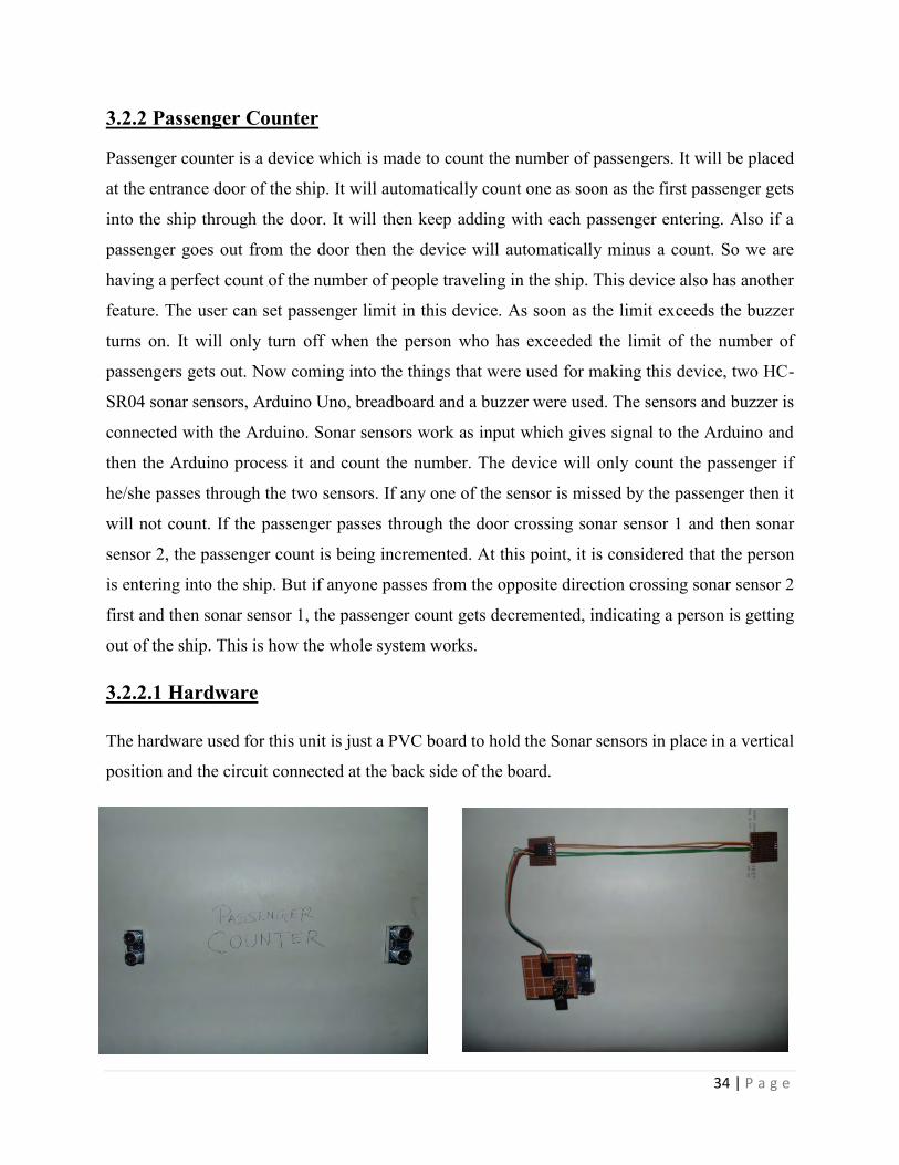
3.2.2.1 Hardware
The hardware used for this unit is just a PVC board to hold the Sonar sensors in place in a vertical
position and the circuit connected at the back side of the board.

35 | P a g e
3.2.2.2 Circuit
All the devices that includes Sonar sensors, NRF24L01 RF module and Power bank are directly
connected to Arduino UNO. The RF module is using the 3.3V voltage input and the sonar sensors
are using the 5V VCC from the Arduino UNO.
Figure1.16: Circuit and
connection diagram of
Passenger Counter unit

36 | P a g e
3.2.2.3 Control
Figure1.17: Control of
Passenger Counter unit

37 | P a g e
3.2.2.4 Communication
There is only one communication that occurs in this unit, which is the RF to RF communication.
RF to RF communication is achieved through the RF pairing of two NRF24L01 RF modules. Since
in this unit, only wireless transmission of data is required so we are using the NRF24L01
transceiver module as a transmitter. For transmitting the data, first we are representing the RF as
a modem to the Arduino UNO, and saving its address in a global array. Then we are invoking a
function that will receive the address of the receiver that the data will be sent to. By setting the
address in this way, we are creating a recognition of the receiver module that the transmitter
module will send to, establishing a pairing between both the modules.
3.2.2.5 Power
To power the whole unit, we are using a 5,000 mAh 5V LiPo Power Bank, which are generally
used for charging mobile phones. This power bank will further be connected to the power supply
of the marine ship, thus providing a seamless supply to the passenger counter and therefore the
station can operate continuously as long as required.
38 | P a g e
3.3 Trigger unit: The function of trigger unit is to trigger the black box during the emergency time. This unit is
made of a water level sensor and a thrower. Essentially the trigger unit is the unit which meets
expectations just single time when the Water vehicle is in great hazardous level. Everything about
the triggering unit is described in the following part.
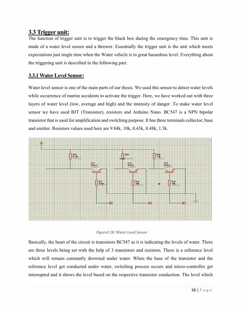
3.3.1 Water Level Sensor: Water level sensor is one of the main parts of our thesis. We used this sensor to detect water levels
while occurrence of marine accidents to activate the trigger. Here, we have worked out with three
layers of water level (low, average and high) and the intensity of danger .To make water level
sensor we have used BJT (Transistor), resistors and Arduino Nano. BC547 is a NPN bipolar
transistor that is used for amplification and switching purpose. It has three terminals collector, base
and emitter. Resistors values used here are 9.84k, 10k, 0.43k, 0.48k, 1.3k.
Basically, the heart of the circuit is transistors BC547 as it is indicating the levels of water. There
are three levels being set with the help of 3 transistors and resistors. There is a reference level
which will remain constantly drowned under water. When the base of the transistor and the
reference level get conducted under water, switching process occurs and micro-controller get
interrupted and it shows the level based on the respective transistor conduction. The level which
Figure1.18: Water Level Sensor

39 | P a g e
goes under water with the reference level gets activated immediately. Starting from level-3, level-
1 will remain at the highest level. Here in this circuit we have defined level-1 as the level that will
act as triggering level. At the Level 1 which is indeed the highest risk level, synchronizing with
other parts of the trigger unit it will trigger the Black Box.
3.3.2 Motor Driver:
The motor driver that has been used is L298D and it is a dual H-bridge motor driver integrated
circuit (IC). This is dual bidirectional motor driver. The design of the circuit is able to control two
motors up to 2A each in both directions. It is ideal for robotic application and it is easy to connect
with microcontroller using couple of wires per motor. It can also be interfaced with simple manual
switches, TTL logic gates, relays etc.
Features:
Logic voltage 5V
Drive voltage 5V-35V
Logic Current 0mA-36mA
Drive current 2A (MAX each bridge)
Maximum Power 25W
Dimensions 43 * 43 * 27 mm
Here the motor driver is used to drive the actuator. When the Arduino turns the motor driver on at
the triggering level then the motor driver operates the actuator according to the instruction given
to it.
3.3.3 Actuator:
An actuator is a type of motor that is used for moving and controlling a mechanism or system. It
is operated by a source of energy like electric current, hydraulic fluid pressure, or pneumatic
pressure and converts that energy into motion. An actuator is the mechanism by which a control
system acts upon an environment. The control system can be simple like a fixed mechanical or

40 | P a g e
electronic system, software based (e.g. a print driver, robot control system), a human or any other
input.
A lead screw actuator has been used in this project and the components of the actuator are motor,
gears, rod, lead screw and nut, power supply. The rod of the actuator is approximately 9cm. The
basic work of actuator here is just to move its shaft outward so that the lock which is locking the
throwing arm gets unlocked. Thus the throwing arm throws the black box in the desired position.
3.3.4 Thrower Cannon:
The design of the thrower cannon is like trebuchet to throw the black box during any accident.
A trebuchet is a blockade engine that was used in the middle ages to destroy masonry walls and to
throw objects like diseased bodies into the castle grounds to infect the inhabitants under siege. Due
to technological advances, trebuchets are no longer used in modern warfare but some still exist for
throwing fire balls. (Lucas)
To make the thrower cannon, the design of the trebuchet has been followed. The thrower cannon
is made of stainless steel in order to make it strong enough to throw the black box and it is made
stainless as it does not readily corrode, rust or stain with water which steel does.
The stand of the thrower cannon is 25 inch and this height is meaningful as the thrower cannon
will be placed at the hull of the ship. The throwing arm of the cannon is made of spring. Four
springs have been used and the reason behind using these springs is there is no counterweight in
this thrower cannon. The tension of the springs are enough high and they are connected with a
circular shaped holder at the top of the stand. The Black Box is actually poised on the holder. So
this spring made throwing arm will throw the Black Box in the water.
At the end of the spring made throwing arm there is a holder which will hold the black box and
the diameter of the ball holder is 8inch and it is made according to the design of the black box so
that it can hold the black box properly. The spring made throwing arm along with the holder has
been locked by a lock and the lock is of 7.1 inch.

41 | P a g e
At the base of the thrower cannon, an actuator has been placed along with a stainless steel lock.
The actuator has been used to open the lock of the throwing arm so that it can throw the black box
under water. A 120 feet long string wire is connected with the black box and this wire is used so
that the black box can be located easily where is has been thrown. Basically when the High
dangerous level of water shows in the water level sensor the entire trigger unit and thrower tosses
the Black Box into the water by moving the actuator external side and expelling the lock from the
holder that is connected with the springs. We used four springs to get a significant amount of force
to throw the ball at least 10 feet away from the affected vehicle.
Measurement of thrower cannon:
Spring holder= 21.5 inch
Stand= 25 inch
Lock= 7.1 inch
Diameter of the ball holder= 8 inch
The throwing arm along with the black box holder will be at 45 degree angle position.
We used the throwing cannon in these styles because we studied the whole physics of trebuchet
and found out that the trebuchet works according to the mass formula. The whole process works
within the mass that is attached with the trebuchet. A trebuchet lives up to expectations by utilizing
the vitality of a falling stabilizer to dispatch a shot (the payload), utilizing mechanical favorable
position to accomplish a high dispatch speed. For greatest dispatch speed the stabilizer must be
much heavier than the payload, since this implies that it will fall rapidly. But instead of using any
payload here we used the elasticity of the springs to throw the ball. Again the trebuchet is well
known for the accuracy but we needed the power and force that is conserved by the spring to throw
the Black Box a little bit far from the actual Marine vehicle to make good use of the string that is
connected to the black box. Moreover only and only by the 120 feet string the affected vehicle can
be traced under the water.

42 | P a g e
3.3.5 Output:
The whole system is working in a very systematic way. When the lower level which is also
regarded as the level-3 gets under water then nothing will happen. When middle level that is level-
2 get under water, the buzzer will turn on which is used to alert the people. Lastly when level-1
goes under water, Arduino Nano turns on the motor driver. Then the motor driver which is
connected with the actuator runs it. The actuator shaft opens the lock and then the throwing arm
throws the box. Again the trebuchet is surely understood for the precision however we required
the force and power that is monitored by the spring to toss the Black Box a tad bit away from the
genuine Marine vehicle to make great utilization of the string that is associated with the black box.
Additionally just and just by the 120 feet string the influenced vehicle can be followed under the
water.
3.3.6 Control:
3.3.7 Power:
The motor driver will remain connected with the power supply of the ship. The actuator used here
is of 12V. So 12V supply is needed to drive the motor driver.
Water sensor Level1
(Triggering level) comes
in contact with water
along with Vref level
Arduino Nano
processes it and runs
the motor driver
Motor driver makes the
actuator shaft go
outward
Lock connected
with the shaft
opens
Black box is
triggered
Figure1.19: Control of Trigger Unit

43 | P a g e
3.3.8 Circuit
Water Level sensor and motor driver are both synchronized and connected with the Arduino Nano.
The outputs of the water sensors are connected with the A1, A2 and A3 pins of the Arduino Nano
respectively.
Connection between motor driver and Arduino Nano is D2, D3, D4 pins of Arduino Nano will be
connected with IN1, IN2 and IN3 pins of the motor driver. D12 pin of the Arduino mini is
connected with the IN4 pin of the motor driver. Output 1 and Output 2 of the motor driver is
connected with actuator. The ground pin of motor driver is connected to the negative end of 12V
battery and the 12 V pin is connected to the positive end of the battery.
Figure 1.20: Connection Diagram of the whole Trigger unit

44 | P a g e
3.4 Software:
As predicted by many, time has actually arrived when digital systems are not anymore meant by
standalone hardware or software rather a blend of both better known as embedded systems.
Hardware functions are being controlled by software’s or data received from sensors are being
used to make decisions with the help of mobile applications. In our project, the black box using
GPS technology gathers its current longitude and latitude and then pushes them along with other
Figure 1.21: Connection Diagram of the whole Trigger unit

45 | P a g e
sensor values received from on board processor to destined web server. Basically the Graphical
User Interface (GUI) part of our project has two parts:
a. Web Database
b. Android Application
Since we intended to design a black box, as a typical feature of it, the exact location in terms of
longitude and latitude of the water vehicle and data of various other sensors used, had to be stored
in a reliable and accessible location. The reason behind we have chosen Android as the mobile
platform is the popularity, this being the most used mobile operating system in the world.
3.4.1 Web Database
For our raw data interface we have gone for a readymade web data storage platform offered by
SparkFun Electronics. They offer a free, robust service for the experimental projects with a storage
limitation of maximum 50MB which we found sufficient for the time being. Data logging to their
web interface also comes with a limitation of 100 pushes in every 15 minute window. Since we
are log data sent from a water vehicle, we have maintained about 5 minutes delay between two
consecutive pushes. While deciding on this time interval we have also been careful and considerate
about the worst possible case of any water vehicle i.e. in case of any unwanted situations the black
box will continuously logging data to our web data base so if the interval is more than the delay
we have kept, we may find difficult to trace the exact location of the black box attached to the
vehicle with a string since the force of the river stream will keep displacing it.
Another reason to choose the data storage service from SparkFun is that it comes up with different
data formats namely JSON, CSV, MySQL, PostgreSQL and ATOM. The interface that SparkFun
public data stream has, looks similar to a table we often see while working with MySQL database
with columns containing variable names and rows having the corresponding values.

46 | P a g e
JSON : JavaScript Object Notation better known shortly as JSON is commonly used lightweight
data-interchange format. This format is easy for humans to understand and also for machines to
parse and generate. Based on a subset of the JavaScript Programming Language, Standard ECMA-
262 3rd Edition - December 1999, it is a text format that is completely language independent but
uses conventions that are familiar to programmers of different programming languages which
makes it ideal as a format to interchange data. In JSON most common forms are:
1. Object : Unordered set consisting name/value pairs beginning with a "{" and ending with "}".
Each name is followed by ":" and the name/value pairs get separated by ",".

47 | P a g e
2. Array: Ordered collection of values unlike Object, beginning with "[" and ending with "]" and
values are separated by ",".
Our raw data interface gives the following output if extracted as JSON format where each row of
the table is turned into an object having multiple name/value pairs separated by "," and whole
collection of objects are fit into an ordered array.

48 | P a g e
3.4.2 Android Application
Mainly implemented to make all the information, that are stored in our raw web database, more
accessible and functional with some added features for the end users. Our primary target was to
echo the entire system designed already for the web server and put together all the variable values
so that they can be more usable for instance the number of people on board is displayed or the
location co-ordinates fetched are being used to show route from our current location to the black
box. The entire graphical user interface has been developed in such a way that it remains friendly
to the users along with proper functionalities. We have used the followings to construct the
application.
a. Eclipse IDE for Java Developers Version: Luna Service Release 1a (4.4.1)
b. Android Software Development Kit (SDK)
c. Android Debugging Tool (ADT)

49 | P a g e
Since one of the major part of our Android application is to show the route from our current
location to the black box on Google map, we needed to incorporate things that are necessary to
develop a Google map based Android application. Initially Google Maps Android API V1 was
released which has now deprecated and now been replaced with API V2 with added features like
search in plain English, Search by voice, Traffic view, Search along route, Satellite view and Street
view.
After incorporating things that are necessary to ensure that the Android application has access to
Google Maps Services, we need to add necessary permissions to the Android Manifest file of the
application.
Figure1.21: Necessary
Permissions

50 | P a g e
Following are the functions of some of these permissions being added to our application:
ACCESS_NETWORK_STATE: to check network state whether data can be downloaded or not
WRITE_EXTERNAL_STORAGE: to write to external storage as Google Maps store map data
ACCESS_COARSE_LOCATION: to determine user location using Wi-Fi and mobile cellular
data
ACCESS_FINE_LOCATION: to determine user location using GPS
Minimum SDK version for our application has been set to Google API level 14 (platform version
Android 4.0, 4.0.1, 4.0.2) which suggests this is the minimum API level required for the
application to run. The Android system will not allow user to install this application if the system's
API level is lower than the defined minimum SDK version.
Target SDK version for an application is meant by the SDK version it targets which suggests the
system that the application have been tested against the target version and no compatibility issues
should arise. The application will able to run on older versions down to the minimum SDK
versions. In our case, we have set this to Google API level 21 (platform version Android 5.0)
We have compiled our application with Google API level 17 (platform version Android 4.2, 4.2.2).
In order to fetch data stored in raw web database to our Android application we have opted for
JSON to interchange data across the platforms. In the following figures show how JSON array has
been initialized and JSON Object has been created. For the application to response faster we have
not iterated through the whole web database, rather we have parsed the latest logged data to know
about the sensor values and last known location of the black box.
Another class named ServiceHandler.java has been implemented to make the url and http requests.
Inside this class, http client has also been initialized and steps taken according to the http request
method types (GET and POST).

51 | P a g e
The main layout or the home of our application consists three main buttons namely "Location",
"Weather" and "Passengers". To make the graphical user experience friendlier another button
named "Help" has also been kept there to instruct the user about how the application works.
Following figure shows the main layout of the application.
When "Location" button is pressed a new activity named "Location Activity" is called showing
the last known latitude and longitude of the black box. To implement one of our main goal that is
to show the exact location of the black box from our current location obtained by inbuilt feature
of Google Map Services "Location".
Figure1.22: Application Layout

52 | P a g e
Following figure shows the Location Activity layout.
From the Main Activity, values of latitude and longitude fields get sent through with the help of
an Intent and those field values are shown in the designated fields of the Location Activity.
Location Activity has a button which if pressed will load the Google map in our application and
will keep our current location at the Centre of the screen. A marker will be placed to the exact
location of the black box and a route (in the Driving mode) will be shown from our current location.
If our current location changes the application will reset the view again bringing the new current
location of the user to the center of the screen, also updating the route to the black box every time
a new location is handled.
GMapV2GetRouteDirection.java class has been implemented to make the HttpClient,
HttpContext, HttpPost, HttpResponse instantiation and add all geopoints to an arraylist so that it
can be put together to be displayed as a complete route on the Google map.
Figure1.23: Location Activity Layout

53 | P a g e
MapActivity Class extends "FragmentActivity" and implements "LocationListener",
"GoogleApiClient.ConnectionCallbacks", "GoogleApiClient.OnConnectionFailedListener".
The figure above shows the Map Layout of our application showing a route to black box location
where a marker has been placed from our current location.
The "Weather" button that has been placed in the main layout of our application opens a new
activity named "Weather Activity" where related sensor values obtained from the on boards
processor of our project such as temperature, humidity and pressure are passed through an intent
so that they can displayed. On a scale of 50 degree Celsius, there has also been implemented a
progress bar to show how critical the temperature value is at that particular point of time.
The figure above shows how an intent is carrying three sensor values to the Weather Activity from
Main Activity and the following figure shows the layout of the Weather Activity.
Figure1.24: Route Direction

54 | P a g e
The "Passengers" button that has been placed in the main layout of our application opens a new
activity named "Passenger Activity" where number of people on board, computed by the
passenger counter and then pushed to our raw data interface, is shown to regulate the excessive
passenger carrying and to mitigate the risk of any maritime accidents. On a scale of 200 people
(considered for our experimental project), there has been designed a progress bar to show the risk
factor concerned depending on the ratio of people on board and the capacity of the water vehicle.
The figure above shows how an intent is carrying three sensor values to the Passenger Activity
from Main Activity and the following figure shows the layout of the Passenger Activity.
Figure1.25: Weather Activity Layout

55 | P a g e
Figure1.26: Passenger Counter Layout

56 | P a g e
Chapter - 4 Data Analysis
4.1 On-Board Processor Analysis
4.1.1 Weather Data Analysis
We have done several experiments with sensors in both constant temperature and also in
various temperatures and took the corresponding readings of the sensor values. We tried to
figure out a relationship between the temperature and pressure and also between temperature
and humidity. For this experiment, we have taken sensor readings of 15 different temperatures
and for each temperature we have taken 25 sets of data for humidity and pressure and then we
took the average of the pressure and humidity for the corresponding temperature.
Temperature Average Pressure(kPa) Average Humidity (%)
21 100.282 53.65
22 100.163 53.65
23 100.137 52.20
24 100.113 52.20
25 100.150 50.20
26 100.109 50.75
27 100.135 49.30
28 100.137 49.30
35 100.244 49.30
36 100.116 49.30
37 100.187 47.85
38 100.212 46.35
39 100.101 45.05
40 100.156 44.95
41 100.206 43.50

57 | P a g e
We plotted the Graph representing Temperature VS Pressure and Humidity. From Graph, it is
understood that humidity changes with of temperature, that is, the percentage humidity decreases
with the increase of temperature. But on the other hand, there was not any significant change in
air pressure at normal conditions but just the rise in temperature. It can be deduced that, since there
was no drastic change in air pressure the temperature conditions were absolutely normal and the
change in humidity was quite clear as the temperature changed.
4.1.2 Passenger Counter Analysis
We have designed a passenger counter in our implemented part that can perform the operation of
counting the number of passengers boarding the ship the increment or decrementing the counter
when required. But it was necessary for us to test that, to how much extent this system can work.
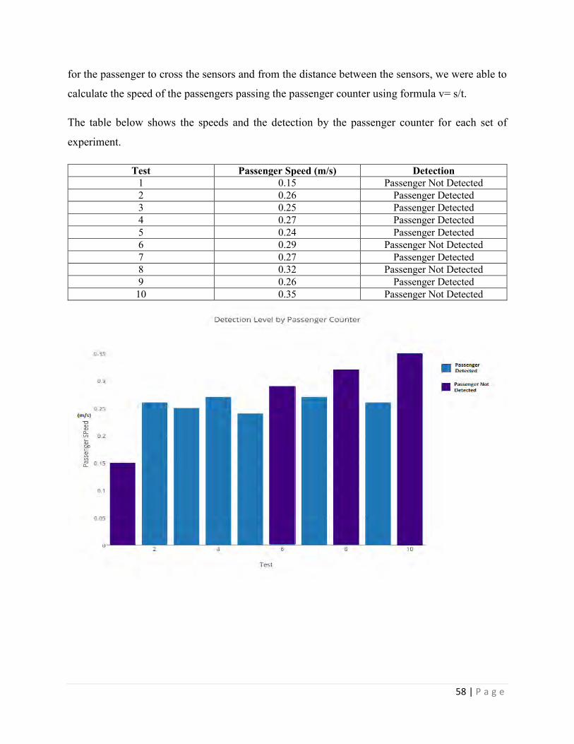
We ran an experiment, to see weather how many people can pass the counter and get detected. We
acquired 10 sets of results for this experiment. Every time, we recorded the amount of time taken
58 | P a g e
for the passenger to cross the sensors and from the distance between the sensors, we were able to
calculate the speed of the passengers passing the passenger counter using formula v= s/t.
The table below shows the speeds and the detection by the passenger counter for each set of
experiment.
Test Passenger Speed (m/s) Detection 1 0.15 Passenger Not Detected 2 0.26 Passenger Detected 3 0.25 Passenger Detected 4 0.27 Passenger Detected 5 0.24 Passenger Detected 6 0.29 Passenger Not Detected 7 0.27 Passenger Detected 8 0.32 Passenger Not Detected 9 0.26 Passenger Detected
10 0.35 Passenger Not Detected

59 | P a g e
From the above results, it is observed that the sensor for the passenger counter is going to work
for a specific range , which is about 0.20m/s to 0.28m/s of speed, beyond this range, the passenger
getting into the ship cannot be recognized and thus give inaccurate information about the
passengers on-board. Therefore, it would tend to work best when people get on board in queue and
move inside the ship at a slow pace.
4.2 Trigger Unit Efficiency Analysis
Since the work of the trigger unit is to eject the Black Box unit with the thrower cannon, it is very
important to determine how much efficient the thrower cannon can be to shoot the Black box unit
during marine accidents. We have tested the thrower cannon with an empty Black Box container
and noted how much distance it can cover when it is thrown from the thrower cannon. We repeated
the same experiment but this time we equipped the Black box container with the Black Box unit
and observed how much it differs from the previous result. We have taken four sets of data to
analysis this, and these are given below:
Test Distance traveled when empty Distance traveled when equipped 1 3.25 2.8
2 4.2 2.9
3 3.92 2.9
4 3.32 3.04

60 | P a g e
From the experiment, we understood that, there is not much variation in the distance covered as
we can observe from the graph that the container covered 3/4th of the distance when empty, when
it was equipped. So it can be easily deduced that, the distance that it cover quite a good amount of
distance and good enough to get ejected from the ship while catastrophe.
4.3 GPS Data Accuracy
According to our project plan, on a critical maritime situation the black box will be triggered away
from the marine vehicle whom it will remain attached until. In such cases if the black box can be
tracked down the water vehicle which potentially faced an accident will be also tracked down since
the black box will remain floating on the water and attached with a string to it. This makes the
accuracy of the logged location co-ordinates from the black box to the raw data interface extremely
significant. The location co-ordinates the black box retrieves using its GPS module which gets
pushed to the web server and the actual location co-ordinates may vary due to various
circumstantial reasons. Therefore, we have taken a set of logged entries by our black box to the
server and compared with the actual exact location of it to find the inconsistency of the GPS data

61 | P a g e
and as the results suggest in the following graph, the location co-ordinates black box gets using
GPS module and the actual co-ordinates are almost identical.
On basis of numerous location co-ordinate data entry, we have found that if we search with 50
meters domain of the location co-ordinates logged to server from the black box, there is 25%
chance to get the black box. Again if the search domain is increased to 100 meters the percentage
of chance to track down the black box successfully, reaches to 50. When we tried to log data from
our University Building no 5, the co-ordinates logged to the server was about 750 meters away
from its exact location. We assume this happened due to presence of number of wireless
communication setups installed in that building which hampered the performance of the black box
in terms of lowering the accuracy of GPS data. That is why we have set the threshold to 800 meters
considering the worst case conditions which suggests if black box is searched with a domain of
the threshold, rescue team is bound to discover the black box meaning the percentage of chance
going to 100.
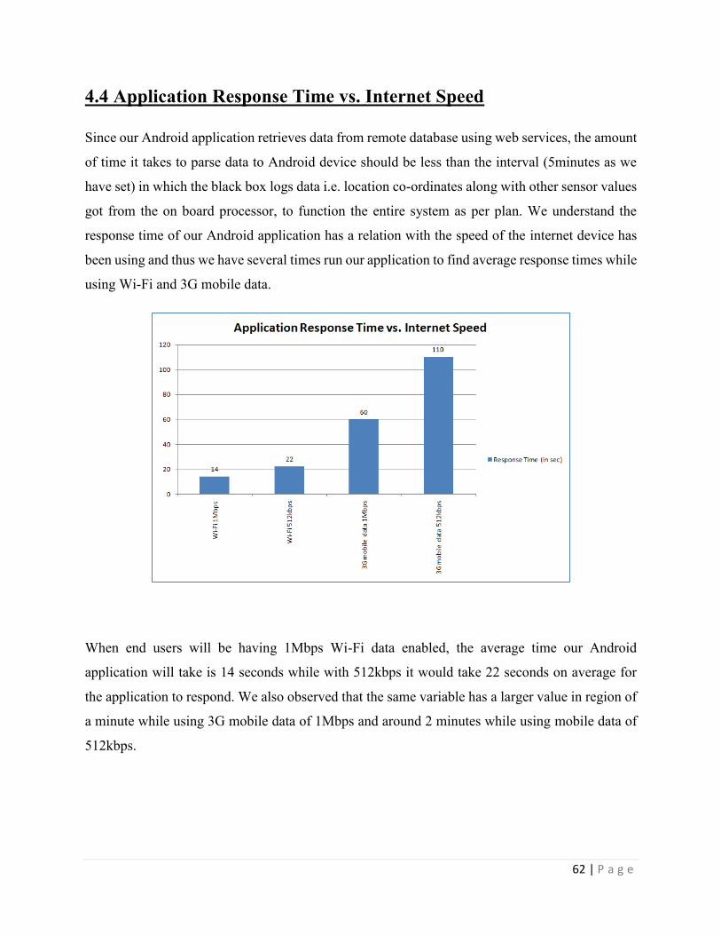
62 | P a g e
4.4 Application Response Time vs. Internet Speed
Since our Android application retrieves data from remote database using web services, the amount
of time it takes to parse data to Android device should be less than the interval (5minutes as we
have set) in which the black box logs data i.e. location co-ordinates along with other sensor values
got from the on board processor, to function the entire system as per plan. We understand the
response time of our Android application has a relation with the speed of the internet device has
been using and thus we have several times run our application to find average response times while
using Wi-Fi and 3G mobile data.
When end users will be having 1Mbps Wi-Fi data enabled, the average time our Android
application will take is 14 seconds while with 512kbps it would take 22 seconds on average for
the application to respond. We also observed that the same variable has a larger value in region of
a minute while using 3G mobile data of 1Mbps and around 2 minutes while using mobile data of
512kbps.

63 | P a g e
4.5 Compatibility across various Android API
The Android application we have developed has the minimum Android API level set to 14 i.e.
Platform Version Android 4.0, 4.0.1, 4.0.2 and the target Android API level set to 21 i.e. Platform
Version Android 5.0. According to the application manifest, any Android device with the system
API level between 14 to 21 should not have any compatibility difficulties. In order to enquire, we
installed our application in five Android devices running on five different system level API and
found out that except for one to two minor user interface issues such as partial progress bar display,
there were no significant difficulties faced by devices to function the application as it was intended
to do.

64 | P a g e
Chapter - 5 Discussion
We have completed our project quite successfully and we had plenty of experiences during the
whole project work. Challenges on different sections of our project made us careful about the next
step. Joys of completing a part motivated our project work more speedy. Overall experience was
such a learning phase for us.
We want to mention that, we tested our project in several circumstances. We found that, the results
are quite satisfactory. From the readings of RF sensors to pushing data on the WEB database,
everything was close to be perfect and quite satisfactory. We designed the passenger counter and
make the counter limit the limited capacity of the water vessel. After experimenting we came to
the result that is working perfectly and it is actually restricts the overloading of the Marine vehicles
as it is one of the main reason of accidents. Moreover our design of black box is close to perfect
as it is completely water proof to save the electrical devices. We also added two platforms for
safety measures. The whole black box is made of stainless steel and very much shock proof to
make the system more eligible to use in the marine vehicles as safety instrument. We also advise
to increase the number of life boats and life jackets to reduce the life loss in the unfortunate marine
accidents. We have to mention that our electrical circuit is very much light and durable to stay a
long time on the water. Again we made it more water proof by using the silicon coating as it will
be very much durable in the water.
The cable attached to the black box is also very much durable to take the force of the strong current
that is normally on the routes we mentioned earlier. We used 120 feet cable initially to experiment
purpose, later we will add more cable after research of all the initiative and depth of the rivers.
Moreover we had a short session where we researched about the average depth of the rivers in our
country. We found out that the average depth of most of the rivers in our country including
Brahamaputra (124 feet), Buriganga (93 feet), Dhaleshwari (119 feet), Kushiyara (33 feet), Naf
(128 feet), Shitalakshya (33 feet), Titas (100 feet) etc. are between the range of 33 feet to 128 feet.

65 | P a g e
So on most of the circumstances, our system of tracking the affected vehicle should be pin point
accurate towards our planning and execution.
On the contrary our system may face significant challenges for the large rivers where average
depth is much more than our expected experimental formats of implementation. Large rivers like
Padma (968 feet), Meghna (1012 feet), Surma (282 feet) etc. where our experimental searching
format can be a big challenge to execute. But we also want to assure that, maximizing the length
of the string we used in our experiment can completely demolish the limitations we explained here
for the large and more average depth rivers.
As we mentioned in the data analysis section, our trigger unit response time is very fast and
accurate and we actually designed a very durable design of thrower cannon which cannot be
affected by the storms and other natural or human calamities. We used water level sensor which
can detect the water levels and make the trigger unit response as soon as danger arrives. The
accuracy level of water level sensor is very good and almost 100% time it worked properly on our
numerous experiments.
We should also add that we have faced some significant challenges to get our desired system
working almost exact parameters. Firstly we had to face the fact of choosing a plan, a project which
is out of the box. We have seen black boxes of Air planes, cars, and rescue systems. Most of them
were just to give an essence to build a successful one. But in the marine side, we basically had
very few papers to get some knowledge of the whole system. We found some systems and papers
which are not related to our system. We actually added the experiences and papers, added up the
electrical, communicational knowledge to make it possible. Again, another challenge was to find
a mechanical structure which is durable at the same time water proof. We researched and found
the sphere shaped black box would be perfect for our desired target.
Moreover after those we had to develop the communication section from on board processor to
the black box. That part was basically the most challenging part of our whole project. We had to
use the RF transmitter and receivers to make the on board processor communicate with the Black
Box. Initially the process was not working. Actually the connection between Arduino Uno and RF
are direct connection. Because in both of the units we used multiple devices such as Barometric
Pressure Sensor and SD card Shield which required the Serial Peripheral Interface along with the

66 | P a g e
RF module. We solved this using an extra Arduino Pro Mini. We connected the RF directly with
the Arduino Pro mini and afterwards made a serial communication between two arduino. This
process required more complex connections and materials which was very time consuming to get
the circuit working.
Another problem we faced about the distance on the application we made to track the black box.
Initially the application distance was differing about 500m or 100m from the exact position as we
explained in the data analysis part. But now at maximum point it gives the exact value or 50m
more or less than on the Google map.
For the time being the Android application we have designed has the minimum API level set to 14
i.e. platform version Android 4.0,4.0.1,4.0.2, which means Android devices with system lower
than minimum API level would not be installed. In future, we plan to revise the application so that
it can be installed on devices running on all available Android API level systems.
Again we have some problem about the trigger unit specifically at the thrower part. We felt
confused about how we can apply the force on the trigger unit. So ultimately we got to work with
the springs to get the force applied to throw the ball. But the problem still exists about the distance.
It covers 10 or less after throwing. We identified the problem. Now we have used 2 springs to be
exact on one side, 4 on the whole unit. We identified that if we use more springs the elasticity
would be better and the thrower will throw further from the affected marine vehicle.
There are some future plans and aspects we have about our project. We believe that the passenger
counter we used that could be more updated and we could have used more justifications over the
process. We have plans to make the passenger counter process to be occupied with the specific
identification of the passengers. Further we have plans to execute it with the biomedical sample as
finger prints. Because at the maximum cases we see that the actual people affected by mishaps
gets missing and even the dead bodies could not be found. So the real identity gets uncovered. So
we thought of these process.
Moreover we have also planned about the mechanical part of the Black Box. Due to technical
difficulties we had to make the one side of the black box flat to make it float. We have plans to
make the whole black box round and make the face of the ball screw thread to open it more
efficiently.

67 | P a g e
Again on the Android application’s weather sensor data part we have only displayed the values of
the sensors after parsing from the raw data interface. In future we have plans to convert this into a
local weather station for the maritime vehicles. We plan to compare the sensor values with the
historical data in terms of the sensor values recorded while water vehicles actually faced accidents
or critical situations. Depending on the comparison results, we would like to give some sort of
notification to the concerned authority that sensor values being gathered are alarming.
To get updated data in our Android application we now need to quit the application and then start
from the beginning. We plan to implement swipe refresh to update the latest value from the
database without coming out of the application.
Another major issue was how will be a route shown when the black box will be logging data to
the designated web server from the middle of the river. We have experimented by setting the black
box mock location to be amidst the water and have seen that the route is shown to the nearest
possible bank. We understand that showing the route up to the nearest possible bank of the river
while the actual black box being within half or one kilometers of distance, is still considered to be
success since the search domain is being reduced to one or two kilometers of radius.
Conclusion:
First of all, we want to express gratitude towards Almighty Allah that we have finished our thesis
effectively and at the same time efficiently. From the earliest starting point to the consummation
of the theory there were various stories loaded with achievement and wretchedness. It is our
pleasure that we picked such a topic where we could explore ourselves, thrown ourselves at the
last point of our test of effectiveness and to the certain point that has its inconceivable impact in
the life of each one. By the time, we experienced and realized the importance of our project looking
at the specific areas which are still so much lack of technologies in the era of digitization. So our
project can be the first step of digitization in the field of Marine transportation system of
Bangladesh. We basically worked on the specific areas where we realized that there we can make
such system where not only loads of lives can be saved but also it can be very efficient and effective
to the development of many areas in the recent developing phase of Bangladesh. We believe our
system is very much easy to operate and at the same time it is very much accurate to make the rate
of marine accidents low by making a strong statement to the awareness of our Water Transport

68 | P a g e
Authority. If our system is enforced into the system of BIWTA the marine accidents can be pretty
much lower and the routes will be very safe. We built the system such efficiently that anyone can
access the basic data of the specific water vessel. The data are such as temperature, air pressure,
humidity and total passengers on board. These information are very much important in the cases
of accidents and finding the reason of accidents. We studied lots of data about the recent marine
mishaps. We found lots of situations and also explained it earlier about the rate of missing launches
and water vessels. With our system these missing mishaps can be much more restricted to the fact
that we have designed the whole system to restrict the loss of missing mishaps.

69 | P a g e
Chapter - 6 Reference
1. AZAD, ABUL KALAM. RIVERINE PASSENGER VESSEL DISASTER
INBANGLADESH: OPTIONS FOR MITIGATION AND SAFETY. Thesis. BRAC
UNIVERSITY, 2009. N.p.: n.p., n.d. RIVERINE PASSENGER VESSEL DISASTER IN
BANGLADESH: OPTIONS FOR MITIGATION AND SAFETY. Postgraduate Programs
in Disaster Management (PPDM). Web.
2. Mohosinul Karim. "Above 4,000 Deaths from Launch Accidents in 38 Years -." Dhaka
Tribune. Dhaka Tribune, 05 May 2014. Web.
3. Musharraf, Yaseer, Maruf Hassan, and Shadman Sakib ‘ A Distanced Machinery
Controlling and Monitoring Guardian.’ Thesis. BRAC UNIVERSITY, 2014. N.p.:
Department Of Electrical and Electronic Engineering;, n.d. A Distanced Machinery
Controlling and Monitoring Guardian. Web.
4. Paluska, Daniel, and Hugh Herr. "The Effect of Series Elasticity on Actuator Power and
Work Output: Implications for Robotic and Prosthetic Joint Design." Robotics and
Autonomous Systems 54.8 (2006): 667-73. Web.
5. "Storms Are Getting Stronger." Http://earthobservatory.nasa.gov/. NASA EARTH
OBSERVATORY, n.d. Web.
6. "Future Voyage Data Recorder Based on Multi-sensors and Human Machine Interface for
Marine Accident." IEEE Xplore. N.p., n.d. Web.
7. Kassem, Abdallah, Rabih Jabr, Ghady Salamouni, and Ziad Khairallah Maalouf. "Vehicle
Black Box System." Vehicle Black Box System (2008): n. pag. Http://ieeexplore.ieee.org/.
IEEE, 10 Apr. 2008. Web. 02 Dec. 2014.
8. Grow, Erica. "Anatomy of a Storm: Pressure Rises and fall." Http://www.wusa9.com/.
Http://www.wusa9.com/, 4 Sept. 2014. Web.
70 | P a g e
9. Nettigo. "Connecting and Programming NRF24L01 with Arduino and Other Boards -
Starter Kit." Starter Kit RSS. N.p., 04 Dec. 2014. Web.
10. Case, Jenn. "Arduino to Arduino Serial Communication." Arduino to Arduino Serial
Communication. Robotic Controls, 06 Feb. 2013. Web.
11. Matthew. "Projects from Tech." : Arduino: Serial Communication Between Two Arduinos.
N.p., 11 May 2013. Web.
12. "Tutorial – Arduino and SIM900 GSM Modules." Tronixstuff. N.p., 08 Jan. 2014. Web.
13. "SIM900 AT Command Manual V1.03." (n.d.): n. pag. Web.
14. "Fundamentals:Radio Frequency Shielding." Architecture Design Handbook:
Fundamentals: Radio Frequency Shielding. N.p., n.d. Web.
15. "4 Popular Methods of GPS Jammers." GPS Systems. N.p., 27 Apr. 2010. Web.
16. Patil, Chetan,Yashwant Marathe, Kiran Amoghimath, and Sumam David. "Low Cost Black
Box for Cars." IEEE Xplore. IEEE, 2013. Web. 12.
17. COHEN, ARIEL E., STEVEN M. CAVALLO, MICHAEL C. CONIGLIO, and HAROLD
E. BROOKS. "A Review of Planetary Boundary Layer Parameterization Schemes and
Their Sensitivity in Simulating Southeastern U.S. Cold Season Severe Weather
Environments." American Meteorological Society. N.p., n.d. Web. 2015.
18. Minkyun Noh, and Seung-Won Kim,. "Flea-Inspired Catapult Mechanism for Miniature
Jumping Robots." IEEE Xplore. IEEE, 5 Oct. 2012. Web.
19. "Flea Inspired Catapult Mechanism with Active Energy Storage and Release for Small
Scale Jumping Robot." IEEE Xplore. N.p., n.d. Web.
20. Sosnowski, Alex. "Drastic Temperature Change For Midwest, East."
www.accuweather.com, n.d. Web.
21. Toothman, Jessika. "Is there really a calm before the storm” 13 May
2008. HowStuffWorks.com. <http://science.howstuffworks.com/nature/climate-
weather/storms/calm-before-storm.html
22. Nagesh, Anirudh, Keshav Khandelwal, and Carlos E. Caicedo. "Accessing External
Databases from Mobile Applications, Technical Report, Center for Convergence and
Emerging Network Technologies." Thesis. Syracuse University, 2014. Accessing External
Databases from Mobile Applications, Technical Report, Center for Convergence and
Emerging Network Technologies. Syracuse University. Web.

71 | P a g e
Chapter- 7 Appendix
7.1 Related Code Section:
Black Box GPS and GSM:
#include <SoftwareSerial.h>
#include <TinyGPS.h>
#include <SPI.h>
#include <SD.h>
const int chipSelect = 8;
float latitude, longitude;
String inputString = ""; // a string to hold incoming data
String hum; // just counter to see if receiving new data
String pre; // temperature
String tem;
String cou;
boolean stringComplete = false; // whether the string is complete
char char1[15];
float humidity; // just counter to see if receiving new data
float pressure; // temperature
float temperature;
int count;
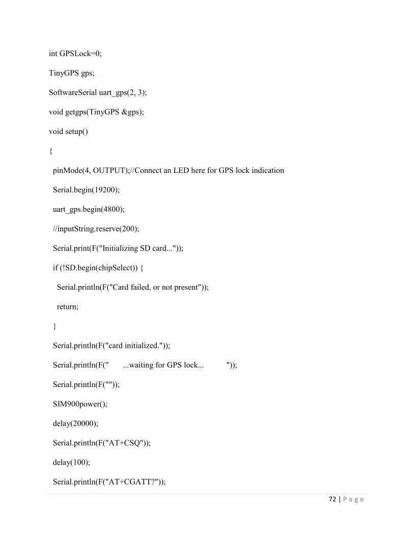
72 | P a g e
int GPSLock=0;
TinyGPS gps;
SoftwareSerial uart_gps(2, 3);
void getgps(TinyGPS &gps);
void setup()
{
pinMode(4, OUTPUT);//Connect an LED here for GPS lock indication
Serial.begin(19200);
uart_gps.begin(4800);
//inputString.reserve(200);
Serial.print(F("Initializing SD card..."));
if (!SD.begin(chipSelect)) {
Serial.println(F("Card failed, or not present"));
return;
}
Serial.println(F("card initialized."));
Serial.println(F(" ...waiting for GPS lock... "));
Serial.println(F(""));
SIM900power();
delay(20000);
Serial.println(F("AT+CSQ"));
delay(100);
Serial.println(F("AT+CGATT?"));

73 | P a g e
delay(100);
Serial.println(F("AT+SAPBR=3,1,\"CONTYPE\",\"GPRS\""));//setting the SAPBR, the
connection type is using gprs
delay(1000);
Serial.println(F("AT+SAPBR=3,1,\"APN\",\"gpinternet\""));//setting the APN, the second need
you fill in your local apn server
delay(4000);
Serial.println(F("AT+SAPBR=1,1"));//setting the SAPBR, for detail you can refer to the AT
command mamual
delay(2000);
}
void SIM900power()
// software equivalent of pressing the GSM shield "power" button
{
delay(4000);
digitalWrite(9, LOW);
delay(1000);
digitalWrite(9, HIGH);
delay(1000);
digitalWrite(9, LOW);
delay(2000);
}

74 | P a g e
void loop()
{
//RFReceive();
while (uart_gps.available()) // While there is data on the RX pin...
{
int c = uart_gps.read(); // load the data into a variable...
if (gps.encode(c)) // if there is a new valid sentence...
{
getgps(gps);
// then grab the data.
}
}
}
// The getgps function will get and print the values we want.
void getgps(TinyGPS &gps)
{
gps.f_get_position(&latitude, &longitude);
// You can now print variables latitude and longitude
if(GPSLock==0){
GPSLock=1;
digitalWrite(4, HIGH);
}
75 | P a g e
Serial.print(F("Lat/Long: "));
Serial.print(latitude, 6);
Serial.print(F(", "));
Serial.println(longitude, 6);
// delay(1000);
// RFReceive();
// delay(1000);
// RFReceive();
// delay(1000);
RFReceive();
SubmitHttpRequest();
sdWrite ();
Serial.println();
delay(30000);
}
void SubmitHttpRequest()
{
Serial.println(F("AT+HTTPINIT")); //init the HTTP request
delay(2000);
Serial.print(F("AT+HTTPPARA=\"URL\",\"http://data.sparkfun.com/input/jq33axOErgin8vLOj
1ra?private_key=zzee6JmW7bF9Ddg4RMmE&latitude="));
Serial.print(latitude, 6);
Serial.print(F("&longitude="));
76 | P a g e
Serial.print(longitude, 6);
Serial.print(F("&pressure="));
Serial.print(pressure, 2);
Serial.print(F("&humidity="));
Serial.print(humidity, 2);
Serial.print(F("&temperature="));
Serial.print(temperature, 2);
Serial.print(F("&passenger_count="));
Serial.print(count);
//Serial.println(value);
Serial.println("\"");
delay(1000);
Serial.println(F("AT+HTTPACTION=1"));//submit the request
Serial.println(F("Data successfully uploaded to server!"));
}
void sdWrite ()
{
String dataString = "";
dataString += String(latitude, 6);
dataString += ",";
dataString += " ";
dataString += String(longitude, 6);
dataString += ",";

77 | P a g e
dataString += " ";
dataString += String(pressure, 2);
dataString += ",";
dataString += " ";
dataString += String(humidity, 2);
dataString += ",";
dataString += " ";
dataString += String(temperature, 2);
dataString += ",";
dataString += " ";
dataString += String(count);
// open the file. note that only one file can be open at a time,
// so you have to close this one before opening another.
File dataFile = SD.open("datalog.txt", FILE_WRITE);
// if the file is available, write to it:
if (dataFile) {
dataFile.println(dataString);
dataFile.close();
// print to the serial port too:
Serial.println(dataString);
Serial.println(F("Data successfully written to SD Card"));
}
// if the file isn't open, pop up an error:

78 | P a g e
else {
Serial.println(F("error opening datalog.txt"));
}
}
void RFReceive() {
while(1){
serialEvent(); //call the function
// print the string when a newline arrives:
if (stringComplete) {
//Serial.println(inputString);
pre=inputString;
hum=inputString;
tem=inputString;
cou=inputString;
int a=pre.indexOf(',');
hum.remove(a);
int b=pre.indexOf(',',(a+1));
pre.remove(0,(a+1));
a=pre.indexOf(',');
pre.remove(a);
int c=cou.lastIndexOf(',');
tem.remove(0,(b+1));
a=tem.indexOf(',');

79 | P a g e
tem.remove(a);
cou.remove(0,(c+1));
pre=pre+"0";
hum=hum+"0";
tem=tem+"0";
pre.toCharArray(char1, pre.length());
pressure=atof(char1);
hum.toCharArray(char1, pre.length());
humidity=atof(char1);
tem.toCharArray(char1, pre.length());
temperature=atof(char1);
cou.toCharArray(char1, pre.length());
count=atoi(char1);
if(((pressure>40)&&(pressure<120))&&((humidity>=10)&&(humidity<=100))&&((temperature
>5)&&(temperature<60))){
Serial.print(pressure,2);
Serial.print(" ");
Serial.print(humidity,2);
Serial.print(" ");
Serial.print(temperature,2);
Serial.print(" ");
Serial.println(count);
Weather station Code:

80 | P a g e
/*
MPL115A1 sparkfun breakout baropressure meter
VDD : 3.3v
GND : GND
SDN : pin 9
CSN : pin 10
SDI/MOSI : pin 11
SDO/MISO : pin 12
SCK : pin 13
DHT11 humidity/temperature sensor
+ : 5v
- : GND
out : pin 2
*/
// the sensor communicates using SPI, so include the library:
#include <SPI.h>
#include "DHT.h"
#define DHTPIN 6
#define DHTTYPE DHT11
DHT dht(DHTPIN, DHTTYPE);
#define PRESH 0x80
#define PRESL 0x82
#define TEMPH 0x84

81 | P a g e
#define TEMPL 0x86
#define A0MSB 0x88
#define A0LSB 0x8A
#define B1MSB 0x8C
#define B1LSB 0x8E
#define B2MSB 0x90
#define B2LSB 0x92
#define C12MSB 0x94
#define C12LSB 0x96
#define CONVERT 0x24
#define chipSelectPin 10
#define shutDown 9
float A0_;
float B1_;
float B2_;
float C12_;
void setup() {
Serial.begin(9600);
dht.begin();
// start the SPI library:
SPI.begin();
// initalize the data ready and chip select pins:
pinMode(shutDown, OUTPUT);

82 | P a g e
digitalWrite(shutDown, HIGH);
pinMode(chipSelectPin, OUTPUT);
digitalWrite(chipSelectPin, HIGH);
delay (10);
// read registers that contain the chip-unique parameters to do the math
unsigned int A0H = readRegister(A0MSB);
unsigned int A0L = readRegister(A0LSB);
A0_ = (A0H << 5) + (A0L >> 3) + (A0L & 0x07) / 8.0;
unsigned int B1H = readRegister(B1MSB);
unsigned int B1L = readRegister(B1LSB);
B1_ = ( ( ( (B1H & 0x1F) * 0x100)+B1L) / 8192.0) - 3 ;
unsigned int B2H = readRegister(B2MSB);
unsigned int B2L = readRegister(B2LSB);
B2_ = ( ( ( (B2H - 0x80) << 8) + B2L) / 16384.0 ) - 2 ;
unsigned int C12H = readRegister(C12MSB);
unsigned int C12L = readRegister(C12LSB);
C12_ = ( ( ( C12H * 0x100 ) + C12L) / 16777216.0 ) ;
}
void loop() {
//Serial.print("Pressure: ");
double x=baropPessure();
if(x<100){
Serial.print("0");

83 | P a g e
}
Serial.print(x,2);
Serial.print(",");
//Serial.print(" kPa ");
// Serial.print("Humidity: ");
Serial.print(humidity());
Serial.print(",");
//Serial.print(" % ");
// Serial.print("Temperature: ");
Serial.println(temperature());
//Serial.println(" *C ");
//delay(1000);
}
//Read registers
unsigned int readRegister(byte thisRegister ) {
unsigned int result = 0; // result to return
digitalWrite(chipSelectPin, LOW);
delay(10);
SPI.transfer(thisRegister);
result = SPI.transfer(0x00);
digitalWrite(chipSelectPin, HIGH);
return(result);
}

84 | P a g e
//read pressure
float baropPessure(){
digitalWrite(chipSelectPin, LOW);
delay(3);
SPI.transfer(0x24);
SPI.transfer(0x00);
digitalWrite(chipSelectPin, HIGH);
delay(3);
digitalWrite(chipSelectPin, LOW);
SPI.transfer(PRESH);
unsigned int presH = SPI.transfer(0x00);
delay(3);
SPI.transfer(PRESL);
unsigned int presL = SPI.transfer(0x00);
delay(3);
SPI.transfer(TEMPH);
unsigned int tempH = SPI.transfer(0x00);
delay(3);
SPI.transfer(TEMPL);
unsigned int tempL = SPI.transfer(0x00);
delay(3);
SPI.transfer(0x00);
delay(3);

85 | P a g e
digitalWrite(chipSelectPin, HIGH);
unsigned long press = ((presH *256) + presL)/64;
unsigned long temp = ((tempH *256) + tempL)/64;
float pressure = A0_+(B1_+C12_*temp)*press+B2_*temp;
float preskPa = pressure* (65.0/1023.0)+50.0;
return(preskPa);
}
float humidity(){
float h = 1.45*dht.readHumidity();
if(h>100){h=100;}
// Read temperature as Celsius (the default)
return(h);
}
float temperature(){
float t = dht.readTemperature();
// Read temperature as Fahrenheit (isFahrenheit = true)
float f = dht.readTemperature(true);
return(t);
}