low & medium voltage power factor correction … · ge digital energy g product description ge...
TRANSCRIPT

GEDigital Energy
g
Product DescriptionGE supplies Low Voltage and Medium Voltage fixed and automatically switched capacitors for power factor correction and harmonic mitigation, in the range of 240V through 13.2kV. GE also supplies active filtering equipment and line/load reactors for specific line and load applications.
GEM™ Series Fixed Capacitors
GEMATIC™ Series Automatically Switched Capacitors
GEMTRAP™ Series for Non-Linear Load Applications
GEM OFW Series for Outdoor Pumping
HWT Medium Voltage series Capacitors
GEMACTIVE™ Active Filter Equipment
GE Line/Load Reactors
GE Matrix Fixed Harmonic Filters
Product Selection & Application Guide
Low & Medium Voltage Power Factor Correction Capacitors, Harmonic Filters and Line/Load Reactors240V through 4800V

GEDigitalEnergy.com2
GE Product Information
Capacitor Technology & Application ..............................................................................3
Facts About GE Low Voltage Capacitors ......................................................................4
Low Voltage Fixed Power Factor - GEM Unit ...............................................................5
Low Voltage Fixed Power Factor - GEM OFW Units & Equipment ..................13
Type HWT Fixed Medium Voltage – Power Factor Correction Capacitors ...........................................................................16
Automatically Switched, Low Voltage Equipment – GEMATIC Compact ......20
Automatically Switched, Low Voltage Equipment – GEMATIC Select ............23
Automatically Switched, Low Voltage Equipment – GEMATIC Custom ...........26
Automatically Switched, Low Voltage Equipment – GEMATIC Quick Response .................................................................................................30
Automatic Low Voltage Harmonic Filter – GEMActive ..........................................32
Fixed Low Voltage Harmonic Filter – GEMTRAP ......................................................34
Low Voltage – Line/Load Reactors ...............................................................................37
Low Voltage – Matrix Broadband Harmonic Filters ..............................................41
Aids For Application of Power Factor Correction Capacitors
Function of Capacitors .......................................................................................................42
Equipment Causing Poor Power Factor .....................................................................42
How Capacitors Save Money ..........................................................................................42
Benefits of Power Factor Improvement .....................................................................43
Facts and Formulas ............................................................................................................44
Degree of Power Factor Improvement ......................................................................45
Size of Capacitor Bank ......................................................................................................45
Determining Your Capacitor Requirements ............................................................45
Sizing Capacitors for Electrical Systems ....................................................................46
Power Bill Savings and Factors That Affect Your Electrical Bill ........................47
Location of Power Capacitors .......................................................................................48
Suggested Maximum Capacitor Ratings ...................................................................49
Switching Capacitors ..........................................................................................................50
Suggested Wire Sizes for Capacitor Installations ...................................................51
Understanding Harmonics ...............................................................................................52
Applying Power Factor Correction in a Harmonic Environment ......................52
Harmonic Survey Data Form ..........................................................................................55
Table of Contents
ApplicAtion And Selection Guide Low & MediuM VoLtage CapaCitors & equipMent
ApplicAtion And Selection Guide Low & MediuM VoLtage CapaCitors & equipMent

GEDigitalEnergy.com 3
Instant “Self-Healing” FeatureDuring a dielectric breakdown an arc occurs across the dielectric at the puncture. The thin metallized electrode will vaporize away from the puncture, then the arc self- extinguishes and bare polypropylene film remains, leaving the capacitor intact. This “self-healing” process is instantaneous - only 0.5 microseconds from initial fault current flow until clearing is complete.
Nuisance Fault and Cell Rupture ProtectedThe patented GE Pressure Sensitive Interrupter (PSI - Fig. 1), in conjunction with the self-clearing feature, helps protect against nuisance faults and cell rupture. This field proven feature interrupts capacitor current when internal pressure forces the cover up and breaks an undercover contact (see Fig. 2).
GEM CapacitorsGE’s GEM capacitors are manufactured with high-grade metallized polypropylene film. Low loss polypropyl-ene film with metallized electrode provides smaller, lighter units. Dielectric self-healing characteristics, plus internal Pressure Sensitive Interrupters, result in a double assurance of safety. Multiple cell construction allows for complete flexibility in capacitor selection.
Capacitor Technology & Application
GE Film/Foil CapacitorsGE’s Film/Foil capacitors offer an energy efficient polypropylene film dielectric. This heavy duty Film/Foil dielectric system is designed to handle unusual overvoltage and overcurrent without reducing capacitor life. The Film/Foil dielectric results in low watts per kVAR power consumption during capacitor operation. The 0.5 watts per kVAR losses and corresponding low internal heat generation mean low operating temperatures for the Film/Foil capacitor, a significant factor in extending capacitor life.
ApplicAtion And Selection Guide Low & MediuM VoLtage CapaCitors & equipMent
ApplicAtion And Selection Guide Low & MediuM VoLtage CapaCitors & equipMent

GEDigitalEnergy.com4
Where to UseGE offers designs that are suitable for either indoor or outdoor use. Connection of the capacitors to the terminals of motors or other loads permits switching the load and capacitors as a unit, automatically keeping kilovar supply in step with kilovar requirement. Capacitors tied to a feeder or bus generally require a switching device. Individual units or groups of units in locations with restricted ventilation, are suitable for operation in maximum ambients of 46°C (115°F). The capacitors are suitable for energizing in temperatures as low as -40°C.
Environmental Compatibility of LiquidGE dielectric systems use the proprietary Dielektrol® family of proven non-PCB biodegradable capacitor fluids specially blended to provide optimum performance. Dielektrol fluids are NGPA rated Class IIIB combustible.
National Electrical CodeThe NEC®, prepared by the National Fire Protection Association, is widely used as the basis for determining the adequacy of electrical installations in the United States. The Code specifically deals with the fusing of capacitors under Article 460-8B. this Article requires low voltage capacitors to have over-current protection in all ungrounded conductors (except if connected on the load side of a motor overload protective device). Three phase capacitors fused only on two phases will not provide adequate protection if a line-to-ground fault should occur in the un-fused phase.
NEC Article 460 in paragraph 460-2 references capacitors containing flammable liquids, “Enclosing and Guarding”. This states that “capacitors containing more than three gallons of flammable liquid shall be enclosed in vaults or outdoor fenced enclosures...“. The code, therefore, permits indoor installation of capacitor cells containing less than three gallons of combustible liquid. All capacitors listed in this catalog contain less than three gallons of liquid.
Capacitor assemblies made up of several units may be installed indoors and, since no single unit contains more than three gallons of the liquid, the installations will be in compliance with the requirements of the NEC.
Line FusesLine fuses are available on both low voltage and medium voltage equipment. Customers should note NEC Article 460-8B to decide if fuses are required for a specific low voltage application.
Discharge ResistorsEach low voltage capacitor includes discharge resistors to drain residual capacitor voltage to 50 volts or less within one minute of de-energization.
The 2400, 4160 and 4800 volt units have discharge resistors that reduce the voltage to 50 volts or less within five minutes.
Long LifeProven field service has confirmed long life demonstrated in comprehensive accelerated life tests, greater than 95 percent survival, 20 years in non-harmonic application.
GE supplies a complete line of low & medium voltage capacitors for power factor correction
Facts About GE Low Voltage Capacitors
ApplicAtion And Selection Guide Low & MediuM VoLtage CapaCitors & equipMent
ApplicAtion And Selection Guide Low & MediuM VoLtage CapaCitors & equipMent

GEDigitalEnergy.com 5
GEM Series Indoor and Outdoor Equipment Fixed Single & Multi-Unit Assemblies
Product Information• 240, 480, 600 volt ratings available
• 240V and 480V 3 phase units are Delta connected
• 600V units are Wye connected
• Additional voltages below 600 volts are available by de-rating (contact factory for details)
• UL Listed
• Discharge resistors reduce voltage to 50 volts or less within one minute
• Enclosure NEMA 3 & 12 (indoor dustproof and outdoor weatherproof)
• Factory installed fuses and blown fuse indicating lights (Optional)
• Pressure Sensitive Interrupter (PSI) in each cell
• Not for use in harmonic applications
DescriptionGEM assemblies feature multiple capacitor cells with metallized polypropylene film dielectric which provides instantaneous self- healing action and reduced energy losses. Safety is provided with the patented GE internal Pressure Sensitive Interrupter (PSI) designed to sense the buildup of pressure if a fault occurs and to interrupt the internal electrical connections before the capacitor cell can rupture. GEM cells feature time-proven Dielektrol, a biodegradable NFPA Class IIIB dielectric fluid. GEM offers high reliability and long life and is suitable for operation over a temperature range of -40°C to 46°C.
Line Fuse/Blown Fuse Indicating LightsWhen fuses are specified, GE provides 100 KAIC and 200 KAIC interrupting capacity fuses for up to 12.5 kVAR and larger ratings respectively. Blown fuse indicating lights are also an option. Order by appropriate BASIC CATALOG number plus the appropriate accessory SUFFIX for a complete catalog number.
MountingGEM 65L800 series units are designed to be mounted upright on any level surface, such as a floor, top of a motor control center, or directly to any wall with brackets provided. 65L900 series require an adapter kit for wall mounting. Wall mounting catalog No. 186C323600005.
Line Connection and Cable EntranceEntrance on Drawing size 1 units must be made through the right end panel. For all other sizes the entrance may be made through either end panel (after first punching out the appropriate size hole). Solderless connectors are provided on each phase.
Low Voltage Fixed Power Factor – GEM Unit
Note: NEC Article 460-8B requires capacitors to have over- current protection in all ungrounded conductors (except if connected on the load side of a motor overload protective device). Three-phase capacitors fused only on two phases will not provide adequate protection if a line-to-ground fault should occur in the un-fused phase.
ApplicAtion And Selection Guide Low & MediuM VoLtage CapaCitors & equipMent
ApplicAtion And Selection Guide Low & MediuM VoLtage CapaCitors & equipMent

GEDigitalEnergy.com6
Low Voltage Fixed Power Factor – GEM Unit
240 VOLT - 3 PHASE 240 VOLT - 1 PHASE APPROXIMATE WEIGHT
kVAR Base Catalog Number
Suffix (No Fuses)
Suffix (Fuses)
Suffix (Fuses & Lights)
Suffix (No Fuses)
Suffix (Fuses)
Suffix (Fuses & Lights) Dwg lbs kg
1.0 65L800 TL1 TN1 TQ1 TX1 TY1 TZ1 1 9 4.11.5 65L801 TL1 TN1 TQ1 TX1 TY1 TZ1 1 9 4.12.0 65L802 TL1 TN1 TQ1 TX1 TY1 TZ1 1 9 4.12.5 65L803 TL1 TN1 TQ1 TX1 TY1 TZ1 1 9 4.13.0 65L804 TL1 TN1 TQ1 TX1 TY1 TZ1 1 9 4.14.0 65L805 TL1 TN1 TQ1 TX1 TY1 TZ1 1 10 4.55.0 65L806 TL1 TN1 TQ1 TX1 TY1 TZ1 1 10 4.56.0 65L807 TL1 TN1 TQ1 TX1 TY1 TZ1 1 11 5.07.5 65L808 TL1 TN1 TQ1 TX1 TY1 TZ1 1 15 6.8
10.0 65L809 TL1 TN1 TQ1 TX1 TY1 TZ1 1 15 6.812.5 65L810 TL2 TN2 TQ2 TX1 TY1 TZ1 1 19 8.615.0 65L811 TL2 TN2 TQ2 TX1 TY1 TZ1 2 19 8.617.5 65L812 TL2 TN2 TQ2 TX1 TY1 TZ1 2 22 10.020.0 65L813 TL2 TN2 TQ2 TX1 TY1 TZ1 2 22 10.022.5 65L814 TL2 TN2 TQ2 TX1 TY1 TZ1 2 32 14.525.0 65L815 TL2 TN2 TQ2 TX1 TY1 TZ1 2 32 14.527.5 65L816 TL2 TN2 TQ2 TX1 TY1 TZ1 3 32 14.530.0 65L817 TL2 TN2 TQ2 TX1 TY1 TZ1 3 32 14.532.5 65L818 TL2 TN2 TQ2 TX1 TY1 TZ1 3 36 16.435.0 65L819 TL2 TN2 TQ2 TX1 TY1 TZ1 3 38 17.337.5 65L820 TL2 TN2 TQ2 TX1 TY1 TZ1 3 38 17.340.0 65L821 TL2 TN2 TQ2 TX1 TY1 TZ1 3 38 17.342.5 65L822 TL2 TN2 TQ2 - - - 3 38 17.345.0 65L823 TL2 TN2 TQ2 - - - 3 38 17.347.5 65L824 TL2 TN2 TQ2 - - - 3 38 17.350.0 65L825 TL2 TN2 TQ2 - - - 3 38 17.355. 0 65L904 T L3 TN 3 TQ 3 TX2 TY2 TZ2 4 87 39. 560. 0 65L905 T L3 TN 3 TQ 3 TX2 TY2 TZ2 4 87 39. 565. 0 65L906 T L3 TN 3 TQ 3 TX2 TY2 TZ2 4 87 39. 570. 0 65L907 T L3 TN 3 TQ 3 TX2 TY2 TZ2 4 89 40. 575. 0 65L908 T L3 TN 3 TQ 3 TX2 TY2 TZ2 4 89 40. 580. 0 65L909 TL 3 TN 3 TQ 3 TX2 TY2 TZ2 4 99 45. 085. 0 65L910 T L3 TN 3 TQ 3 TX2 TY2 TZ2 4 99 45. 090. 0 65L911 T L3 TN 3 TQ 3 TX2 TY2 TZ2 4 99 45. 095. 0 65L912 T L3 TN 3 TQ 3 TX2 TY2 TZ2 4 99 45. 0
100. 0 65L913 T L3 TN 3 TQ 3 TX2 TY2 TZ2 4 99 45. 0110. 0 65L914 T L3 TN 3 TQ 3 TX2 TY2 TZ2 5 136 61. 8120. 0 65L915 T L3 TN 3 TQ 3 TX2 TY2 TZ2 5 136 61. 8125. 0 65L916 T L3 TN 3 TQ 3 TX2 TY2 TZ2 5 136 61. 8130. 0 65L917 T L3 TN 3 TQ 3 TX2 TY2 TZ2 5 142 64. 5140. 0 65L918 T L3 TN 3 TQ 3 TX2 TY2 TZ2 5 148 67. 3150. 0 65L919 T L3 TN 3 TQ 3 TX2 TY2 TZ2 5 148 67. 3160. 0 65L920 T L3 TN 3 TQ 3 TX2 TY2 TZ2 6 181 82. 3170. 0 65L921 T L3 TN 3 TQ 3 TX2 TY2 TZ2 6 181 82. 3175. 0 65L922 T L3 TN 3 TQ 3 TX2 TY2 TZ2 6 186 84. 5180. 0 65L923 T L3 TN 3 TQ 3 TX2 TY2 TZ2 6 186 84. 5190. 0 65L924 T L3 TN 3 TQ 3 TX2 TY2 TZ2 6 191 86. 8200. 0 65L925 T L3 TN 3 TQ 3 TX2 TY2 TZ2 6 196 89. 1210. 0 65L926 T L3 TN 3 TQ 3 TX2 TY2 TZ2 7 230 104. 5220. 0 65L927 T L3 TN 3 TQ 3 TX2 TY2 TZ2 7 230 104. 5230. 0 65L928 T L3 TN 3 TQ 3 TX2 TY2 TZ2 7 235 106. 8240. 0 65L929 T L3 TN 3 TQ 3 TX2 TY2 TZ2 7 240 109. 1250. 0 65L930 T L3 TN 3 TQ 3 TX2 TY2 TZ2 7 245 111. 4
Fixed GEM Unit Selection Table - 240V - Three Phase & Single Phase
ApplicAtion And Selection Guide Low & MediuM VoLtage CapaCitors & equipMent
ApplicAtion And Selection Guide Low & MediuM VoLtage CapaCitors & equipMent

GEDigitalEnergy.com 7
Low Voltage Fixed Power Factor – GEM Unit
480 VOLT – 3 PHASE WEIGHT 480 VOLT – 3 PHASE WEIGHT
kVARBase
Catalog Number
Suffix (No
Fuses)
Suffix (Fuses)
Suffix (Fuses & Lights)
Dwg lbs kg kVARBase
Catalog Number
Suffix (No
Fuses)
Suffix (Fuses)
Suffix (Fuses & Lights)
Dwg lbs kg
1.0 65L800 TA1 TC1 TE1 1 9 4.1 90.0 65L833 TA1 TC1 TE1 3 38 17.2
1.5 65L801 TA1 TC1 TE1 1 9 4.1 95.0 65L834 TA1 TC1 TE1 3 38 17.2
2.0 65L802 TA1 TC1 TE1 1 9 4.1 100.0 65L835 TA1 TC1 TE1 3 38 17.2
2.5 65L803 TA1 TC1 TE1 1 9 4.1 110.0 65L914 TA2 TC2 TE2 4 87 39.5
3.0 65L804 TA1 TC1 TE1 1 9 4.1 120.0 65L915 TA2 TC2 TE2 4 87 39.5
4.0 65L805 TA1 TC1 TE1 1 9 4.1 125.0 65L916 TA2 TC2 TE2 4 87 39.5
5.0 65L806 TA1 TC1 TE1 1 9 4.1 130.0 65L917 TA2 TC2 TE2 4 87 39.5
6.0 65L807 TA1 TC1 TE1 1 9 4.1 140.0 65L918 TA2 TC2 TE2 4 89 40.8
7.5 65L808 TA1 TC1 TE1 1 10 4.5 150.0 65L919 TA2 TC2 TE2 4 89 40.8
10.0 65L809 TA1 TC1 TE1 1 10 4.5 160.0 65L920 TA2 TC2 TE2 4 99 44.9
12.5 65L810 TA1 TC1 TE1 1 10 4.5 170.0 65L921 TA2 TC2 TE2 4 99 44.9
15.0 65L811 TA1 TC1 TE1 1 13 5.9 175.0 65L922 TA2 TC2 TE2 4 99 44.9
17.5 65L812 TA1 TC1 TE1 1 13 5.9 180.0 65L923 TA2 TC2 TE2 4 99 44.9
20.0 65L813 TA1 TC1 TE1 1 13 5.9 190.0 65L924 TA2 TC2 TE2 4 99 44.9
22.5 65L814 TA1 TC1 TE1 1 13 5.9 200.0 65L925 TA2 TC2 TE2 4 99 44.9
25.0 65L815 TA1 TC1 TE1 1 13 5.9 210.0 65L926 TA2 TC2 TE2 5 136 61.7
27.5 65L816 TA1 TC1 TE1 2 19 8.6 220.0 65L927 TA2 TC2 TE2 5 136 61.7
30.0 65L817 TA1 TC1 TE1 2 19 8.6 230.0 65L928 TA2 TC2 TE2 5 136 61.7
32.5 65L818 TA1 TC1 TE1 2 19 8.6 240.0 65L929 TA2 TC2 TE2 5 138 62.6
35.0 65L819 TA1 TC1 TE1 2 19 8.6 250.0 65L930 TA2 TC2 TE2 5 138 62.6
37.5 65L820 TA1 TC1 TE1 2 19 8.6 260.0 65L931 TA2 TC2 TE2 5 142 64.4
40.0 65L821 TA1 TC1 TE1 2 22 10.0 270.0 65L932 TA2 TC2 TE2 5 143 64.9
42.5 65L822 TA1 TC1 TE1 2 22 10.0 280.0 65L933 TA2 TC2 TE2 5 148 67.1
45.0 65L823 TA1 TC1 TE1 2 22 10.0 290.0 65L934 TA2 TC2 TE2 5 148 67.1
47.5 65L824 TA1 TC1 TE1 2 22 10.0 300.0 65L935 TA2 TC2 TE2 5 148 67.1
50.0 65L825 TA1 TC1 TE1 2 22 10.0 325.0 65L936 TA2 TC2 TE2 6 181 82.1
55.0 65L826 TA1 TC1 TE1 3 32 14.5 350.0 65L937 TA2 TC2 TE2 6 186 84.4
60.0 65L827 TA1 TC1 TE1 3 32 14.5 375.0 65L338 TA2 TC2 TE2 6 191 86.6
65.0 65L828 TA1 TC1 TE1 3 32 14.5 400.0 65L939 TA2 TC2 TE2 6 196 88.9
70.0 65L829 TA1 TC1 TE1 3 33 15.0 425.0 65L940 TA2 TC2 TE2 7 230 104.3
75.0 65L830 TA1 TC1 TE1 3 33 15.0 450.0 65L941 TA2 TC2 TE2 7 235 106.6
80.0 65L831 TA1 TC1 TE1 3 38 17.2 475.0 65L942 TA2 TC2 TE2 7 240 108.9
85.0 65L832 TA1 TC1 TE1 3 38 17.2 500.0 65L943 TA2 TC2 TE2 7 245 111.1
Fixed GEM Unit Selection Table - 480V – Three Phase (Contact Factory for Single Phase Product)
ApplicAtion And Selection Guide Low & MediuM VoLtage CapaCitors & equipMent
ApplicAtion And Selection Guide Low & MediuM VoLtage CapaCitors & equipMent

GEDigitalEnergy.com8
Low Voltage Fixed Power Factor – GEM Unit
600 VOLT -3 PHASE APPROXIMATE WEIGHT 600 VOLT – 3 PHASE APPROXIMATE
WEIGHT
kVARBase
Catalog Number
Suffix (No
Fuses)
Suffix (Fuses)
Suffix (Fuses & Lights)
Dwg lbs kg kVARBase
Catalog Number
Suffix (No
Fuses)
Suffix (Fuses)
Suffix (Fuses & Lights)
Dwg lbs kg
1.0 65L800 TF1 TH1 TK1 1 9 4.1 90.0 65L833 TF2 TH2 TK2 3 38 17.3
1.5 65L801 TF1 TH1 TK1 1 9 4.1 95.0 65L834 TF2 TH2 TK2 3 38 17.3
2.0 65L802 TF1 TH1 TK1 1 9 4.1 100.0 65L835 TF2 TH2 TK2 3 38 17.3
2.5 65L803 TF1 TH1 TK1 1 9 4.1 110.0 65L914 TF3 TH3 TK3 4 87 39.5
3.0 65L804 TF1 TH1 TK1 1 9 4.1 120.0 65L915 TF3 TH3 TK3 4 87 39.5
4.0 65L805 TF1 TH1 TK1 1 9 4.1 125.0 65L916 TF3 TH3 TK3 4 87 39.5
5.0 65L806 TF1 TH1 TK1 1 10 4.1 130.0 65L917 TF3 TH3 TK3 4 87 39.5
6.0 65L807 TF1 TH1 TK1 1 10 4.1 140.0 65L918 TF3 TH3 TK3 4 89 40.5
7.5 65L808 TF1 TH1 TK1 1 10 4.5 150.0 65L919 TF3 TH3 TK3 4 99 40.5
10.0 65L809 TF2 TH2 TK2 1 10 4.5 160.0 65L920 TF3 TH3 TK3 4 99 45
12.5 65L810 TF2 TH2 TK2 1 10 4.5 170.0 65L921 TF3 TH3 TK3 4 99 45
15.0 65L811 TF1 TH1 TK1 1 13 5.9 175.0 65L922 TF3 TH3 TK3 4 99 45
17.5 65L812 TF2 TH2 TK2 1 13 5.9 180.0 65L923 TF3 TH3 TK3 4 99 45
20.0 65L813 TF2 TH2 TK2 1 13 5.9 190.0 65L924 TF3 TH3 TK3 4 99 45
22.5 65L814 TF2 TH2 TK2 1 13 5.9 200.0 65L925 TF3 TH3 TK3 4 99 45
25.0 65L815 TF2 TH2 TK2 1 13 5.9 210.0 65L326 TF3 TH3 TK3 5 136 61.8
27.5 65L816 TF2 TH2 TK2 2 19 8.6 220.0 65L927 TF3 TH3 TK3 5 136 61.8
30.0 65L817 TF2 TH2 TK2 2 19 8.6 230.0 65L928 TF3 TH3 TK3 5 136 61.8
32.5 65L818 TF2 TH2 TK2 2 19 8.6 240.0 65L929 TF3 TH3 TK3 5 138 62.7
35.0 65L819 TF2 TH2 TK2 2 19 8.6 250.0 65L930 TF3 TH3 TK3 5 138 62.7
37.5 65L820 TF2 TH2 TK2 2 19 8.6 260.0 65L931 TF3 TH3 TK3 5 142 64.5
40.0 65L821 TF2 TH2 TK2 2 22 10.0 270.0 65L932 TF3 TH3 TK3 5 143 65
42.5 65L822 TF2 TH2 TK2 2 22 10.0 280.0 65L933 TF3 TH3 TK3 5 148 67.3
45.0 65L823 TF2 TH2 TK2 2 22 10.0 290.0 65L934 TF3 TH3 TK3 5 148 67.3
47.5 65L824 TF2 TH2 TK2 2 22 10.0 300.0 65L935 TF3 TH3 TK3 6 148 67.3
50.0 65L825 TF2 TH2 TK2 2 22 10.0 325.0 65L936 TF3 TH3 TK3 6 181 82.3
55.0 65L826 TF2 TH2 TK2 3 32 14.5 350.0 65L937 TF3 TH3 TK3 6 186 84.5
60.0 65L827 TF2 TH2 TK2 3 32 14.5 375.0 65L938 TF3 TH3 TK3 6 191 86.8
65.0 65L828 TF2 TH2 TK2 3 32 14.5 400.0 65L939 TF3 TH3 TK3 6 196 89.1
70.0 65L829 TF2 TH2 TK2 3 33 15.0 425.0 65L940 TF3 TH3 TK3 7 230 104.5
75.0 65L830 TF2 TH2 TK2 3 33 15.0 450.0 65L941 TF3 TH3 TK3 7 235 106.8
80.0 65L831 TF2 TH2 TK2 3 38 17.3 475.0 65L942 TF3 TH3 TK3 7 240 109.1
85.0 65L832 TF2 TH2 TK2 3 38 17.3 500.0 65L943 TF3 TH3 TK3 7 245 111.4
Fixed GEM Unit Selection Table - 600V – Three Phase (Contact Factory for Single Phase Product)
ApplicAtion And Selection Guide Low & MediuM VoLtage CapaCitors & equipMent
ApplicAtion And Selection Guide Low & MediuM VoLtage CapaCitors & equipMent

GEDigitalEnergy.com 9
Low Voltage Fixed Power Factor – GEM Unit
Fixed GEM Unit Drawings
Figure 1
Figure 2
(2).406 DIA HOLES
8.00
(B)
6.12(A)
4.62(B)
10.80(A)
12.00(A)12.60(A)
.250-20 THDFOR GRD CONN.
NP
NP
NP
NP267219
101N140
(4).312 X.500 SLOTS
1.88
(B)
4.00
(A)
6.00
(A)
1.00(A)
3.94(B)
7.00
(B)
BLOWNFUSE
INDICATINGLIGHT
THD.FOR LINE CONN.
QQ or SCR
6.12[155](A)
12.00[305](B)
12.60[320](B)
10.80[274](B)
6.00
[152
](A)
4.00
[102
](A)
7.50
[191
](B)
3.94
[100
](B)
4.62
[117
](B)
7.00
[178
](B)
14.1
2[35
9](B
)
1.00[25](A)
(2).406 DIAHOLES
101N140WARNING
LABEL
101N108CAUTION
LABEL
(4).31x.50SLOTS
NP267203CAPACITOR
RATING LABEL
101N117DIELEKTROL
FLUID LABEL
CSA
UL
.25-20x0.75 BOLTFOR LINE CONN.
BLOWNFUSE
INDICATINGLIGHT
ApplicAtion And Selection Guide Low & MediuM VoLtage CapaCitors & equipMent
ApplicAtion And Selection Guide Low & MediuM VoLtage CapaCitors & equipMent

GEDigitalEnergy.com10
Low Voltage Fixed Power Factor – GEM Unit
Fixed GEM Unit Drawings
Figure 3
Figure 4
6.12[155](A)
12.00[305](B)
12.60[320](B)
10.80[274](B)
6.00
[152
](A)
4.00
[102
](A)
12.3
8[3
14](B
)3.
94[1
00](B
)
4.62
[117
](B)
7.00
[178
](B)
23.3
8[59
4](B
)
1.00[25](A)
(2).406 DIAHOLES
101N140WARNING
LABEL
101N108CAUTION
LABEL
(4).31x.50SLOTS
101N117DIELEKTROL
FLUID LABEL
NP267203CAPACITOR
RATING LABELUL
CSA
.25-20x.41 THD.FOR GRD. CONN.
.31-18x1.00 BOLTFOR LINE CONN.
BLOWN FUSEINDICATING LIGHT
ApplicAtion And Selection Guide Low & MediuM VoLtage CapaCitors & equipMent
ApplicAtion And Selection Guide Low & MediuM VoLtage CapaCitors & equipMent

GEDigitalEnergy.com 11
Low Voltage Fixed Power Factor – GEM Unit
Fixed GEM Unit Drawings
Figure 5
Figure 6
4.12
35.00[889]
33.50[851]
31.00[787]
27.00[686]
32.35[822]
4.12[105]
21.75[552]
13.40[340]
13.06[332]
12.00[305]
8.00[203]
3.00[76]
1" DIA.LIFTINGHOLES
(4).562 BASEMOUNTING HOLES
(4).562 WALLMOUNTING HOLES
GRD. CONN. FOR NO. 6-250 MCM
LINE CONN. FOR 4/0-600 MCM FRONT VIEW
SHOWN WITH TOP/FRONT COVER REMOVED
(4).562 BASEMOUNTING
HOLES
NP220452 RATING PLATE
WARNING LABEL
CAPACITOR RATING LABEL
FLUID LABEL
FLUID LABEL
CAPACITOR RATING LABEL
UL/CSA LABEL
101N108 CAUTION
LABEL
OPTIONALWALL MOUNTING
KIT SHOWN
FLUID LABEL
CAPACITOR RATING LABEL
BLOWN FUSEINDICATING LIGHTS
4.12
45.00[1143]
43.50[1105]
41.00[1041]
37.00[940]
32.35[822]
4.12[105]
21.75[552]
13.40[340]
13.06[332]
12.00[305]
8.00[203]
3.00[76]
1" DIA.LIFTINGHOLES
(4).562 BASEMOUNTING HOLES
(4).562 WALLMOUNTING HOLES
GRD. CONN. FOR NO. 6-250 MCM
LINE CONN. FOR 4/0-600 MCM FRONT VIEW
SHOWN WITH TOP/FRONT COVER REMOVED
(4).562 BASEMOUNTING
HOLES
NP220452 RATING PLATE
WARNING LABEL
CAPACITOR RATING LABEL
FLUID LABEL
FLUID LABEL
CAPACITOR RATING LABEL
UL/CSA LABEL
101N108 CAUTION
LABEL
OPTIONALWALL MOUNTING
KIT SHOWN
FLUID LABEL
CAPACITOR RATING LABEL
FLUID LABEL
CAPACITOR RATING LABEL
BLOWN FUSEINDICATING LIGHTS
ApplicAtion And Selection Guide Low & MediuM VoLtage CapaCitors & equipMent
ApplicAtion And Selection Guide Low & MediuM VoLtage CapaCitors & equipMent

GEDigitalEnergy.com12
Low Voltage Fixed Power Factor – GEM Unit
Fixed GEM Unit Drawings
Figure 7
4.12
55.00[1397]
53.50[1359]
51.00[1295]
47.00[1194]
32.35[822]
4.12[105]
21.75[552]
13.40[340]
13.06[332]
12.00[305]
8.00[203]
3.00[76]
1" DIA.LIFTINGHOLES
(4).562 BASEMOUNTING HOLES
(4).562 WALLMOUNTING HOLES
GRD. CONN. FOR NO. 6-250 MCM
LINE CONN. FOR 4/0-600 MCM
FRONT VIEWSHOWN WITH TOP/FRONT
COVER REMOVED
(4).562 BASEMOUNTING
HOLES
NP220452 RATING PLATE
WARNING LABEL
ULLABEL
101N108 CAUTION
LABEL
OPTIONALWALL MOUNTING
KIT SHOWN
CAPACITOR RATING LABELCSA
FLUID LABEL
CAPACITOR RATING LABELCSA
FLUID LABEL
CAPACITOR RATING LABELCSA
FLUID LABEL
CAPACITOR RATING LABELCSA
FLUID LABEL
CAPACITOR RATING LABELCSA
FLUID LABEL
BLOWN FUSEINDICATING LIGHTS
ApplicAtion And Selection Guide Low & MediuM VoLtage CapaCitors & equipMent
ApplicAtion And Selection Guide Low & MediuM VoLtage CapaCitors & equipMent

GEDigitalEnergy.com 13
GEM OFW SeriesMotor and Pump Capacitors
Product Information• 240, 480 volt ratings available
• Outdoor Weatherproof
• Three Phase Delta, 60Hz
DescriptionThese Type GEM capacitors are designed primarily for the motor requirements of oil field and other pumping installations. Their application, however, may be extended to other motor applications installed indoor or outdoor. Type GEM OFW capacitors feature multiple cells which are assembled in parallel in a NEMA 3 enclosure. Each capacitor cell features the patented GE Pressure Sensitive Interrupter (PSI) that protects against cell rupture. The metallized polypropylene film dielectric system provides an instantaneous self-healing action and greatly reduced energy losses.
Discharge resistors are included to reduce voltage to 50 volts or less within one minute of de-energization. A 4 ft 4-conductor flexible cable is provided for easy installation.
Type GEM capacitors offer high reliability and long life. They are suitable for operation over a temperature range of –40°C to +46°C. GEM also features Dielektrol impregnant which is a biodegradable Class IIIB combustible fluid.
Note: These capacitors are not intended for use in harmonic environments.
Line Connection and Cable EntranceA 4 ft. 4-conductor flexible cable with watertight connector is provided for easy installation.
Low Voltage Fixed Power Factor – GEM OFW Units & Equipment
ApplicAtion And Selection Guide Low & MediuM VoLtage CapaCitors & equipMent
ApplicAtion And Selection Guide Low & MediuM VoLtage CapaCitors & equipMent

GEDigitalEnergy.com14
Low Voltage Fixed Power Factor – GEM OFW Units & Equipment
A B APPROXIMATE WEIGHT
Volts kVAR Catalog Number Cable Size inches mm inches mm lbs kg
240 1.0 65L550TL1 12 5.9 150 3.18 81 7.5 3.4
1.5 65L551TL1 12 5.9 150 3.18 81 7.5 3.4
2.0 65L552TL1 12 5.9 150 3.18 81 7.5 3.4
2.5 65L553TL1 12 5.9 150 3.18 81 7.8 3.5
3.0 65L554TL1 12 5.9 150 3.18 81 7.8 3.5
4.0 65L555TL1 12 5.9 150 3.18 81 8.5 3.9
5.0 65L556TL1 12 5.9 150 3.18 81 8.5 3.9
6.0 65L557TL1 8 5.94 151 5.54 141 10.2 4.6
7.5 65L558TL1 8 5.94 151 5.54 141 11.7 5.3
10.0 65L559TL1 8 5.94 151 5.54 141 11.7 5.3
12.5 65L560TL1 8 5.94 151 8.15 207 14.9 6.8
15.0 65L561TL1 8 5.94 151 8.15 207 14.9 6.8
480 1.0 65L550TA1 12 5.9 150 3.18 81 7.5 3.4
1.5 65L551TA1 12 5.9 150 3.18 81 7.5 3.4
2.0 65L552TA1 12 5.9 150 3.18 81 7.5 3.4
2.5 65L553TA1 12 5.9 150 3.18 81 7.5 3.4
3.0 65L554TA1 12 5.9 150 3.18 81 7.5 3.4
4.0 65L555TA1 12 5.9 150 3.18 81 7.5 3.4
5.0 65L556TA1 12 5.9 150 3.18 81 7.5 3.4
6.0 65L557TA1 12 5.9 150 3.18 81 7.8 3.5
7.5 65L558TA1 12 5.9 150 3.18 81 8.5 3.9
10.0 65L559TA1 12 5.9 150 3.18 81 8.5 3.9
12.5 65L560TA1 12 5.9 150 3.18 81 8.5 3.9
15.0 65L561TA1 8 5.94 151 5.54 141 11.7 5.3
17.5 65L562TA1 8 5.94 151 5.54 141 11.7 5.3
20.0 65L563TA1 8 5.94 151 5.54 141 11.7 5.3
22.5 65L564TA1 8 5.94 151 5.54 141 11.7 5.3
25.0 65L565TA1 8 5.94 151 5.54 141 11.7 5.3
27.5 65L566TA1 8 5.94 151 8.15 207 14.9 6.8
30.0 65L567TA1 8 5.94 151 8.15 207 14.9 6.8
Fixed GEM OFW Selection Table - 240V 480V Three Phase (For dimensions please see Figure 1)
ApplicAtion And Selection Guide Low & MediuM VoLtage CapaCitors & equipMent
ApplicAtion And Selection Guide Low & MediuM VoLtage CapaCitors & equipMent

GEDigitalEnergy.com 15
1.12 REF.
(2).500 DIA. HOLES
1.38
9.50
12.50N
P267
203
101N
117E
11.50
CONDUCTOR CABLE
48.00±.50
1.50"A"
1.58(B)
"B"
Low Voltage Fixed Power Factor – GEM OFW Units & Equipment
GEM OFW Series Drawings
Figure 1
ApplicAtion And Selection Guide Low & MediuM VoLtage CapaCitors & equipMent
ApplicAtion And Selection Guide Low & MediuM VoLtage CapaCitors & equipMent

GEDigitalEnergy.com16
Medium Voltage Fixed Capacitors
Product Information• 2400, 4160, 4800, 6600, 7200, 12470, 13200 volt ratings available
• Additional voltages below 13.2kV are available by de-rating (contact factory for details)
• Indoor Dustproof and Outdoor Weatherproof
• Three Phase Delta, 60Hz
• Not for use in harmonic applications
DescriptionHWT’s Film/Foil capacitors offer an energy efficient polypropylene film dielectric. This heavy duty conventional film dielectric system is designed to handle unusual overvoltages and overcurrents without reducing capacitor life. The Film/Foil dielectric results in low watts per kVAR power consumption during capacitor operation. The less than 0.2 watts per kVAR losses and corresponding low internal heat generation mean low operating temperatures for the Film/Foil capacitor, a significant factor in extending capacitor life. Film/Foil designs feature time-proven Dielektrol, a biodegradable NFPA Class IIIB dielectric fluid. This design offers high reliability and long life and is suitable for operation over a temperature range of -40°C to +46°C.
Line TerminalsSolderless connectors are provided on each phase:
Assembly Connector Size
One unit #10 - #4Two unit #14 - 1/0
Three unit #6 - 250 MCM
FusesProtection is provided by 50,000 ampere interrupting capacity current limiting fuses. A pop-up button on the fuse gives visual indication of a blown fuse.
MountingHWT equipments are designed to be mounted upright on any level surface.
Type HWT Fixed Medium Voltage – Power Factor Correction Capacitors
ApplicAtion And Selection Guide Low & MediuM VoLtage CapaCitors & equipMent
ApplicAtion And Selection Guide Low & MediuM VoLtage CapaCitors & equipMent
GEDigitalEnergy.com 17
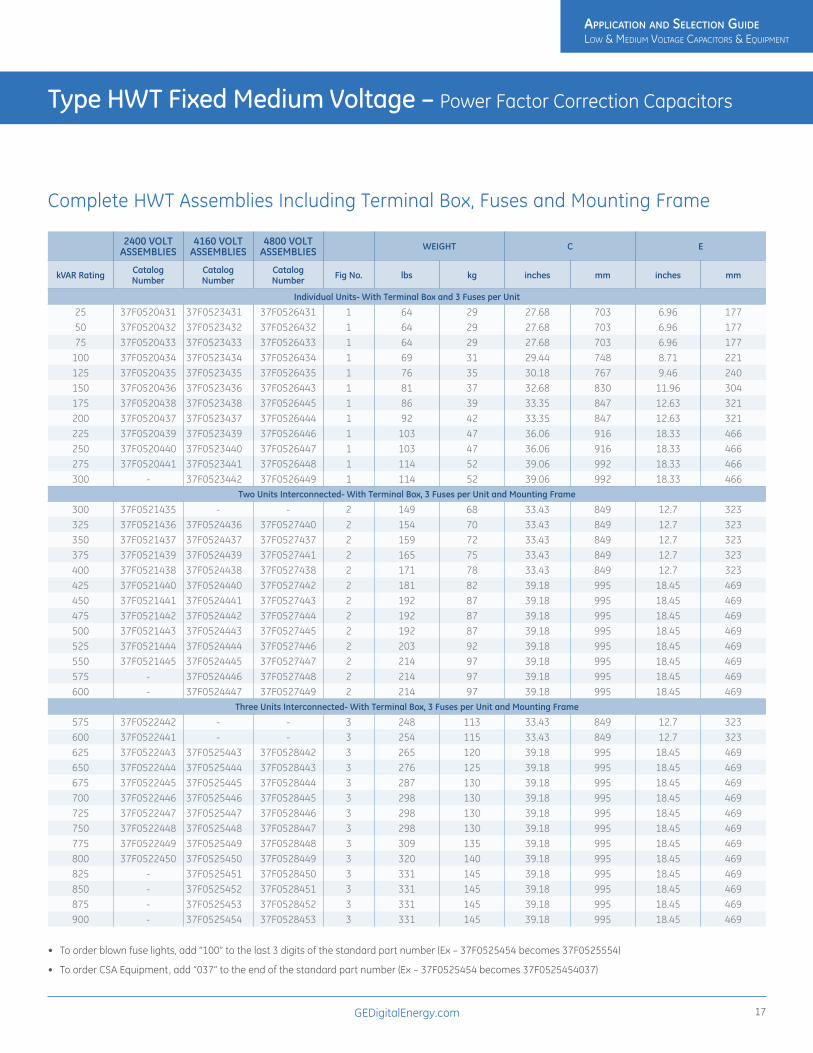
Type HWT Fixed Medium Voltage – Power Factor Correction Capacitors
2400 VOLT ASSEMBLIES
4160 VOLT ASSEMBLIES
4800 VOLT ASSEMBLIES WEIGHT C E
kVAR Rating Catalog Number
Catalog Number
Catalog Number Fig No. lbs kg inches mm inches mm
Individual Units- With Terminal Box and 3 Fuses per Unit
25 37F0520431 37F0523431 37F0526431 1 64 29 27.68 703 6.96 17750 37F0520432 37F0523432 37F0526432 1 64 29 27.68 703 6.96 17775 37F0520433 37F0523433 37F0526433 1 64 29 27.68 703 6.96 177
100 37F0520434 37F0523434 37F0526434 1 69 31 29.44 748 8.71 221125 37F0520435 37F0523435 37F0526435 1 76 35 30.18 767 9.46 240150 37F0520436 37F0523436 37F0526443 1 81 37 32.68 830 11.96 304175 37F0520438 37F0523438 37F0526445 1 86 39 33.35 847 12.63 321200 37F0520437 37F0523437 37F0526444 1 92 42 33.35 847 12.63 321225 37F0520439 37F0523439 37F0526446 1 103 47 36.06 916 18.33 466250 37F0520440 37F0523440 37F0526447 1 103 47 36.06 916 18.33 466275 37F0520441 37F0523441 37F0526448 1 114 52 39.06 992 18.33 466300 - 37F0523442 37F0526449 1 114 52 39.06 992 18.33 466
Two Units Interconnected- With Terminal Box, 3 Fuses per Unit and Mounting Frame
300 37F0521435 - - 2 149 68 33.43 849 12.7 323325 37F0521436 37F0524436 37F0527440 2 154 70 33.43 849 12.7 323350 37F0521437 37F0524437 37F0527437 2 159 72 33.43 849 12.7 323375 37F0521439 37F0524439 37F0527441 2 165 75 33.43 849 12.7 323400 37F0521438 37F0524438 37F0527438 2 171 78 33.43 849 12.7 323425 37F0521440 37F0524440 37F0527442 2 181 82 39.18 995 18.45 469450 37F0521441 37F0524441 37F0527443 2 192 87 39.18 995 18.45 469475 37F0521442 37F0524442 37F0527444 2 192 87 39.18 995 18.45 469500 37F0521443 37F0524443 37F0527445 2 192 87 39.18 995 18.45 469525 37F0521444 37F0524444 37F0527446 2 203 92 39.18 995 18.45 469550 37F0521445 37F0524445 37F0527447 2 214 97 39.18 995 18.45 469575 - 37F0524446 37F0527448 2 214 97 39.18 995 18.45 469600 - 37F0524447 37F0527449 2 214 97 39.18 995 18.45 469
Three Units Interconnected- With Terminal Box, 3 Fuses per Unit and Mounting Frame
575 37F0522442 - - 3 248 113 33.43 849 12.7 323600 37F0522441 - - 3 254 115 33.43 849 12.7 323625 37F0522443 37F0525443 37F0528442 3 265 120 39.18 995 18.45 469650 37F0522444 37F0525444 37F0528443 3 276 125 39.18 995 18.45 469675 37F0522445 37F0525445 37F0528444 3 287 130 39.18 995 18.45 469700 37F0522446 37F0525446 37F0528445 3 298 130 39.18 995 18.45 469725 37F0522447 37F0525447 37F0528446 3 298 130 39.18 995 18.45 469750 37F0522448 37F0525448 37F0528447 3 298 130 39.18 995 18.45 469775 37F0522449 37F0525449 37F0528448 3 309 135 39.18 995 18.45 469800 37F0522450 37F0525450 37F0528449 3 320 140 39.18 995 18.45 469825 - 37F0525451 37F0528450 3 331 145 39.18 995 18.45 469850 - 37F0525452 37F0528451 3 331 145 39.18 995 18.45 469875 - 37F0525453 37F0528452 3 331 145 39.18 995 18.45 469900 - 37F0525454 37F0528453 3 331 145 39.18 995 18.45 469
• To order blown fuse lights, add “100” to the last 3 digits of the standard part number (Ex – 37F0525454 becomes 37F0525554)
• To order CSA Equipment, add “037” to the end of the standard part number (Ex – 37F0525454 becomes 37F0525454037)
Complete HWT Assemblies Including Terminal Box, Fuses and Mounting Frame
ApplicAtion And Selection Guide Low & MediuM VoLtage CapaCitors & equipMent
ApplicAtion And Selection Guide Low & MediuM VoLtage CapaCitors & equipMent

GEDigitalEnergy.com18
Type HWT Fixed Medium Voltage Correction Capacitors Drawings
Figure 1
Figure 2
Figure 3
NP
NP
NP
21.08
15.62
16.58
11.34
(2).500X.625 SLOTS
NP
101N140LOCATE ONCENTER OFCOVER
4.38.17
SOLDERLESS CONN.FOR #10 SOLID TO #4 STR'D COND.
"C"
"E"
NP
(4).562MOUNTING
HOLES
15.75
17.1517.50
14.50
19.75 21.08
"C"
"E"
.25-20GRD SCR.
TERMINAL FOR#6 TO 250MCM CABLE
BLOWN FUSEINDICATINGLIGHTS
CONNECTIONFOR USER
SUPPLIED120V POWER
NP
(4).562MOUNTING
HOLES
15.75
17.15
14.50
24.50
26.75 21.08
"C"
"E"
BLOWN FUSEINDICATINGLIGHTS
CONNECTIONFOR USER
SUPPLIED120V POWER
TERMINAL FOR#6 TO 250MCM CABLE
.25-20GRD SCR.
Type HWT Fixed Medium Voltage – Power Factor Correction Capacitors
ApplicAtion And Selection Guide Low & MediuM VoLtage CapaCitors & equipMent
ApplicAtion And Selection Guide Low & MediuM VoLtage CapaCitors & equipMent

GEDigitalEnergy.com 19
Type HWT Fixed Medium Voltage – Power Factor Correction Capacitors
2400 VOLTS 4160 VOLTS 4800 VOLTS
kVAR Unit Catalog Number
Fuse Catalog Number Amps Unit Catalog
NumberFuse Catalog
Number Amps Unit Catalog Number
Fuse Catalog Number Amps
25 52L301WS60 115A161400653 35 52L302WS60 115A161400656 18 52L303WS61 115A161400656 18
50 51L301WS60 115A161400653 35 51L302WS60 115A161400656 18 51L303WS60 115A161400656 18
75 51L304WS60 115A161400653 35 51L305WS60 115A161400656 18 51L306WS60 115A161400656 18
100 54L303WS60 115A161400654 75 54L304WS60 115A161400658 50 54L305WS60 115A161400666 25
125 54L306WS60 115A161400654 75 54L307WS60 115A161400658 50 54L310WS60 115A161400666 25
150 54L308WS60 115A161400654 75 54L309WS60 115A161400658 50 54L403WS60 115A161400658 50
175 54L317WS60 115A161400654 75 54L313WS60 115A161400658 50 54L311WS60 115A161400658 50
200 58L302WS60 115A161400655 100 58L303WS60 115A161400658 50 58L424WS60 115A161400658 50
225 16L0153WS3 115A161400655 100 16L0156WS3 115A161400658 50 16L0160WS3 115A161400658 50
250 16L0154WS3 115A161400655 100 16L0157WS3 115A161400671 75 16L0161WS3 115A161400658 50
275 16L0155WS3 115A161400655 100 16L0158WS3 115A161400671 75 16L0162WS3 115A161400671 75
300 - - - 16L0159WS3 115A161400671 75 16L0163WS3 115A161400671 75
• Top and bottom fuse adapter kit is required for each fuse. One kit per fuse is needed and contains 1 top and 1 bottom fuse adapter. Catalog number for fuse adapter kit is 308A390100001.
• For CSA labeled capacitors, order with 037 suffix added (Ex – 54L304WS60 becomes 54L304WS60037)
Individual HWT Units and Fuses
ApplicAtion And Selection Guide Low & MediuM VoLtage CapaCitors & equipMent
ApplicAtion And Selection Guide Low & MediuM VoLtage CapaCitors & equipMent

GEDigitalEnergy.com20
GEMATIC Compact240 - 480 - 600 volts 3 phase 60 Hz
DescriptionGEMATIC multi-step power factor control equipment automatically maintains desired power factor level, adjusting to system load requirements in selected kVAR steps. The solid-state control responds to a current signal from the optional current trans- former and to a voltage signal from a potential transformer included in the equipment.
GEMATIC equipments feature capacitors with a metallized dielectric system providing a self-healing action and reduced energy losses. The biodegradable impregnant is a class IIIB combustible fluid. Discharge resistors reduce the voltage to 50 volts or less within one minute of de-energization. The capacitor cells are 3 phase and are designed for 110% of rated voltage, 135% of rated current , and, 135% of rated kVAR.
The power factor controller requires a CT signal for operation. The CT primary should be sized for the total phase current to be compensated (capacitor current and load current). Typically, the total phase current should be 50% to 80% of the CT primary rating. The CT secondary is rated 5A. The CT is connected to one phase of the equipment and the factory installed PT is connected across the other two phases.
Standard Equipment Features• Correction to unity power factor, if desired
• UL and cUL listed
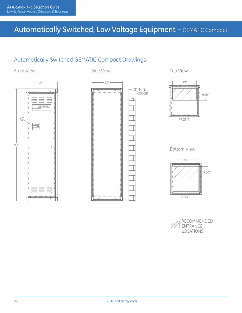
• NEMA 1, 12-gauge steel cabinet enclosure with ANSI® #70 light grey paint
• Dimensions are 25” W x 25”D x 90”H
• Removable lifting eyes
• Safety door interlock to prevent door from being opened while equipment is energized
• Microprocessor-based controller with built-in voltage and harmonic alarms provides safe and rapid indication of potential or real failure; Digital display of power factor, current, and capacitor step status
• Manual switching capability
• External current transformer connections provided
• 65 KAIC bracing (may be limited by breaker rating)
• Plated copper bus
• LED capacitor stage display
• Air core inductors to limit inrush currents and transients
• Industrial duty, UL recognized safety disconnect, metallized dielectric capacitors, less than 0.2 watts per KVAR losses employing 200 kAIC current limiting fuses in all 3 phases
• Designed to minimize installation time and costs
• Top entry
• Convection cooling - no fans required
• Ratings: 120 KVAR maximum at 240 volts 300 KVAR maximum at 480 and 600 volts
Optional Equipment Features• Blown fuse indicator lights or push to test lights
• NEMA 3R cabinet available (contact factory)
• Bottom entry
• Split core current transformer
• Hand-off auto switches
• Molded case circuit breaker internally mounted with external operator
• Power on/off switch
Automatically Switched, Low Voltage Equipment – GEMATIC Compact
ApplicAtion And Selection Guide Low & MediuM VoLtage CapaCitors & equipMent
ApplicAtion And Selection Guide Low & MediuM VoLtage CapaCitors & equipMent

GEDigitalEnergy.com 21
Automatically Switched, Low Voltage Equipment – GEMATIC Compact
Volts kVAR Base Catalog Number kVAR/Step Breaker
Rating Weight
240 40 37FJ2040D205 20 400 499
60 37FJ3060D205 20 400 572
80 37FJ4080D205 20 400 602
100 37FJ5100D205 20 400 630
120 37FJ6120D205 20 600 662
480 50 37FJ2050F255 25 400 499
75 37FJ2075F255 25 400 499
100 37FJ3100F255 25 400 542
125 37FJ3125F255 25 400 565
150 37FJ3150F505 50 400 572
175 37FJ4175F255 25 400 595
200 37FJ4200F505 50 400 602
225 37FJ5225F255 25 600 625
250 37FJ5250F505 50 600 630
275 37FJ6275F255 25 600 655
300 37FJ6300F505 50 600 662
600 50 37FJ2050H255 25 400 499
75 37FJ2075H255 25 400 499
100 37FJ3100H255 25 400 542
125 37FJ3125H255 25 400 565
150 37FJ3150H505 50 400 572
175 37FJ4175H255 25 400 595
200 37FJ4200H505 50 400 602
225 37FJ5225H255 25 400 625
250 37FJ5250H505 50 400 630
275 37FJ6275H255 25 600 655
300 37FJ6300H505 50 600 660
To order breaker or blown fuse lights or both options, see below:
Suffix Letter Option
L Blown Fuse LightsB BreakerR Lights & Breaker
Note: Add only one suffix letter to the end of catalog numbers. Add breaker option below, after Suffix Letter Option.
Breaker Options:
Current Rating kAIC Rating Code for Standard Breaker Option
400 35 00003600 35 00006
Note: Breaker Option suffix number goes after the Option Suffix Letter.
GEMATIC Compact – 240-480-600 Volt-3 Phase – 60 Hz
ApplicAtion And Selection Guide Low & MediuM VoLtage CapaCitors & equipMent
ApplicAtion And Selection Guide Low & MediuM VoLtage CapaCitors & equipMent
GEDigitalEnergy.com22
Automatically Switched, Low Voltage Equipment – GEMATIC Compact
Automatically Switched GEMATIC Compact Drawings
Front View Side View Top View
Bottom View
1
90"
25" 25"
9.00"
19"
9.00"
19"3" MIN.INDOOR
FRONT
FRONT
ENTRANCELOCATIONS
RECOMMENDED
GEMATIC
1
90"
25" 25"
9.00"
19"
9.00"
19"3" MIN.INDOOR
FRONT
FRONT
ENTRANCELOCATIONS
RECOMMENDED
GEMATIC1
90"
25" 25"
9.00"
19"
9.00"
19"3" MIN.INDOOR
FRONT
FRONT
ENTRANCELOCATIONS
RECOMMENDED
GEMATIC
1
90"
25" 25"
9.00"
19"
9.00"
19"3" MIN.INDOOR
FRONT
FRONT
ENTRANCELOCATIONS
RECOMMENDED
GEMATIC
1
90"
25" 25"
9.00"
19"
9.00"
19"3" MIN.INDOOR
FRONT
FRONT
ENTRANCELOCATIONS
RECOMMENDED
GEMATIC
ApplicAtion And Selection Guide Low & MediuM VoLtage CapaCitors & equipMent
ApplicAtion And Selection Guide Low & MediuM VoLtage CapaCitors & equipMent

GEDigitalEnergy.com 23
GEMATIC Select240 - 480 - 600 volts 3 phase 60 Hz
DescriptionGEMATIC multi-step power factor control equipment automatically maintains desired power factor level, adjusting to system load requirements in selected kVAR steps. The solid-state control responds to a current signal from the optional current trans- former and to a voltage signal from a potential transformer included in the equipment.
GEMATIC equipments feature capacitors with a metallized dielectric system providing a self-healing action and reduced energy losses. The biodegradable impregnant is a class IIIB combustible fluid. Discharge resistors reduce the voltage to 50 volts or less within one minute of de-energization. The capacitor cells are 3 phase and are designed for 110% of rated voltage, 135% of rated current, and, 135% of rated kVAR.
The power factor controller requires a CT signal for operation. The CT primary should be sized for the total phase current to be compensated (capacitor current and load current). Typically, the total phase current should be 50% to 80% of the CT primary rating. The CT secondary is rated 5A. The CT is connected to one phase of the equipment and the factory installed PT is connected across the other two phases.
Standard Equipment Features• Correction to unity power factor, if desired
• UL and cUL listed
• NEMA 1 steel cabinet enclosure with ANSI #70 light grey paint. Top entry, right side.
• Dimensions are 48” W x 24”D x 90”H
• Removable lifting eyes
• Safety door interlock to prevent door from being opened while equipment is energized
• Microprocessor-based controller with built-in voltage and harmonic alarms provides safe and rapid indication of potential or real failure. Digital display of power factor, current and capacitor step status
• Manual switching capability
• External current transformer connections provided
• 100 KAIC bracing (may be limited by breaker rating)
• Capacitor stage display
• Air core inductors to limit inrush currents and transients
• Industrial duty, metallized electrode capacitors, employing
• 200 KAIC current-limiting fuses in all 3 phases
• Plated copper bus
• Lockable door handle
• Designed to minimize installation time and costs.
• Convection cooling - no fans required
• Ratings: 300 KVAR maximum at 240 volts, 600 KVAR maximum at 480 and 600 volts
Optional Equipment Features• Blown fuse indicator lights or push to test lights
• NEMA 4 cabinet available
• NEMA 12 cabinet available
• Split core current transformer
• Molded-case circuit breaker internally mounted with external operator
• Hands-off auto switches
• Power on/off switch with light
• Bottom entry (Entry location right side of enclosure)
Automatically Switched, Low Voltage Equipment – GEMATIC Select
ApplicAtion And Selection Guide Low & MediuM VoLtage CapaCitors & equipMent
ApplicAtion And Selection Guide Low & MediuM VoLtage CapaCitors & equipMent

GEDigitalEnergy.com24
Automatically Switched, Low Voltage Equipment – GEMATIC Select
Volts kVAR Base Catalog Number kVAR/Step Breaker
Rating Weight
240 100 37FC4100D255 25 400 1050125 37FC5125D255 25 600 1099150 37FC6150D255 25 600 1149175 37FC7175D255 25 800 1198200 37FC8200D255 25 800 1248225 37FC9225D255 25 1000 1298250 37FCA250D255 25 1000 1347300 37FCC300D255 25 1200 1446
480 100 37FC3100F255 25 400 976125 37FC3125F255 25 400 988150 37FC3150F505 50 400 1000175 37FC4175F255 25 400 1038200 37FC4200F505 50 400 1050225 37FC5225F255 25 600 1085250 37FC5250F505 50 600 1099275 37FC6275F255 25 600 1136300 37FC6300F505 50 600 1149325 37FC7325F255 25 600 1186350 37FC7350F505 50 800 1198375 37FC8375F255 25 800 1235400 37FC8400F505 50 800 1248425 37FC9425F255 25 800 1285450 37FC9450F505 50 1000 1298475 37FCA475F255 25 1000 1334500 37FCA500F505 50 1000 1347525 37FCB525F255 25 1000 1384550 37FCB550F505 50 1200 1397575 37FCC575F255 25 1200 1433600 37FCC600F505 50 1200 1446
600 100 37FC3100H255 25 400 976125 37FC3125H255 25 400 988150 37FC3150H505 50 400 1000175 37FC4175H255 25 400 1038200 37FC4200H505 50 400 1050225 37FC5225H255 25 400 1085250 37FC5250H505 50 400 1099275 37FC6275H255 25 400 1136300 37FC6300H505 50 600 1149325 37FC7325H255 25 600 1186350 37FC7350H505 50 600 1198375 37FC8375H255 25 600 1235400 37FC8400H505 50 600 1248425 37FC9425H255 25 800 1285450 37FC9450H505 50 800 1298475 37FCA475H255 25 800 1334500 37FCA500H505 50 800 1347525 37FCB525H255 25 800 1384550 37FCB550H505 50 800 1397575 37FCC575H255 25 1000 1433600 37FCC600H505 50 1000 1446
To order breaker or blown fuse lights or both options, see below:
Suffix Letter Option
L Blown Fuse LightsB BreakerR Lights & Breaker
Note: Add only one suffix letter to the end of catalog numbers. Add breaker option below, after Suffix Letter Option.
Breaker Options:
Current Rating kAIC Rating Code for Standard Breaker Option
400 35 00003600 35 00006800 50 00009
1000 50 0000C1200 50 0000F
Note: Breaker Option suffix number goes after the Option Suffix Letter. Additional step sizes available. Please contact factory.
GEMATIC Select – 240- 480- 600 Volts – 3 Phase- 60 Hz
ApplicAtion And Selection Guide Low & MediuM VoLtage CapaCitors & equipMent
ApplicAtion And Selection Guide Low & MediuM VoLtage CapaCitors & equipMent

GEDigitalEnergy.com 25
Automatically Switched, Low Voltage Equipment – GEMATIC Select
Automatically Switched GEMATIC Select Drawings
Front View Side View
Top View Bottom ViewSIDE VIEW
90"
FRONT VIEW
48"
BOTTOM VIEW
1/2"
SCREEN
47"
4 X 1/2" HOLE
16" 20"
14"3"
TOP VIEW
24"2" MIN.INDOOR 3"
ENTRANCELOCATIONS
RECOMMENDED
SIDE VIEW
90"
FRONT VIEW
48"
BOTTOM VIEW
1/2"
SCREEN
47"
4 X 1/2" HOLE
16" 20"
14"3"
TOP VIEW
24"2" MIN.INDOOR 3"
ENTRANCELOCATIONS
RECOMMENDED
SIDE VIEW
90"
FRONT VIEW
48"
BOTTOM VIEW
1/2"
SCREEN
47"
4 X 1/2" HOLE
16" 20"
14"3"
TOP VIEW
24"2" MIN.INDOOR 3"
ENTRANCELOCATIONS
RECOMMENDED
SIDE VIEW
90"
FRONT VIEW
48"
BOTTOM VIEW
1/2"
SCREEN
47"
4 X 1/2" HOLE
16" 20"
14"3"
TOP VIEW
24"2" MIN.INDOOR 3"
ENTRANCELOCATIONS
RECOMMENDED
ApplicAtion And Selection Guide Low & MediuM VoLtage CapaCitors & equipMent
ApplicAtion And Selection Guide Low & MediuM VoLtage CapaCitors & equipMent

GEDigitalEnergy.com26
GEMATIC Custom240 - 480 - 600 volts 3 phase 60 Hz
DescriptionThe GEMATIC Custom offers power factor correction with the flexibility of including harmonic filter reactors initially or adding them later if they are required.
Many of today’s power systems require modern solutions to power factor correction. The rapid increase in variable speed drive use and other solid state devices has resulted in severe harmonic loads on power systems. GE has many years of experience in preventing the occurrence of non-sinusoidal resonance. Successful integration in tuned L-C networks solves the problem of parallel resonance.
GEMATIC Custom automatic power factor correction systems with 3-phase harmonic suppression reactors are application specific. Accordingly, each installation requires specific information to aid GE application engineers in designing each system to meet your requirements. This information should include, but not be limited to, kVAR requirements, transformer size and impedance, kVAsc of the transformer, and a harmonic profile of your system. Load characteristic at the time of the survey and worst case should also be included.
The GEMATIC Custom systems may be configured for the addition of harmonic suppression reactors in the future to meet the imminent needs of your system. This reduces initial investment and provides a readily made retrofit package. This system provides total flexibility in achieving maximum automatic power factor correction. Please contact the local GE sales office or the GE factory for any assistance with your particular power factor correction and harmonic suppression needs.
Standard Equipment Features • Designed and built to “match and line up” with motor control centers and
switchgear
• Industrial rated design and specifications
• Modular design permits sizing of cabinet to allow for future expansion requirements
• Correction to unity power factor, if desired
• NEMA 1 steel cabinet enclosure with ANSI #70 light grey paint, 12-gauge frame and 14-gauge panels
• Removable lifting eyes
• UL and cUL listed
• Microprocessor-based controller with built-in voltage, temperature, and harmonic alarms provides safe and rapid indication of potential or real failure; Digital display of power factor, current, and capacitor step status
• Manual switching capability
• External current transformer connections provided
• 100 KAIC bracing (may be limited by breaker rating)
• Plated copper bus
• Top entry, right hand feed
• Capacitor stage display
• Industrial duty, metallized electrode capacitors, employing 200 KAIC current-limiting fuses in all 3 phases
• Air core inductors to limit inrush currents and transients (Not required when tuned reactors are utilized)
• Designed to minimize installation time and costs
• Door interlock to prevent entry while system is energized
• Lockable door handle
• Convection cooling - no fans required
Optional Equipment Features• Outdoor NEMA 3R enclosure
• Main breaker
• Iron core harmonic suppression reactors
• Reactor thermal alarm
• Blown fuse indicating lights or push to test lights
• Split core current transformer
• Molded case circuit breaker, internally mounted with external operator or system breaker
• Hands-off auto switches
• Reverse and bottom entry
• Power on/off switch
Automatically Switched, Low Voltage Equipment – GEMATIC Custom
ApplicAtion And Selection Guide Low & MediuM VoLtage CapaCitors & equipMent
ApplicAtion And Selection Guide Low & MediuM VoLtage CapaCitors & equipMent

GEDigitalEnergy.com 27
Automatically Switched, Low Voltage Equipment – GEMATIC Custom
Many of today’s power systems require modern solutions to power factor correction. The rapid increase in non-linear load devices, such as variable speed drives, AC/DC drives, arc-furnaces, and welders, has resulted in severe harmonic loads on power systems.
GE has many years of experience in preventing the occurrence of non-sinusoidal resonance. Successful integration in tuned L-C networks solves the problem of parallel resonance.
The GEMATIC Custom automatic power factor correction systems with 3-phase harmonic suppression reactors are application-specific. Accordingly, each installation requires specific information to aid GE Application Engineers in designing a system to meet your requirements.
This information should include, but not be limited to, KVAR requirements, transformer size and impedance, KVAsc of the transformer, and a harmonic profile of your system. Load characteristics at the time of the survey and worst case should also be included.
The GEMATIC Custom systems may be configured for the addition of harmonic suppression reactors in the future to meet the imminent needs of your system. This reduces initial investment and provides a ready-made retrofit package.
The GEMATIC Custom system provides total flexibility in achieving maximum automatic power factor correction. Please contact GE for any assistance with your particular power factor correction and harmonic suppression needs.
Custom System with Harmonic Suppression Reactors
Volts Total kVAR
Base Catalog Number
kVAR/Step
Circuit Breaker Rating
Enclosure Width
(Sections)
Weight (without reactors)
Weight (with
reactors)
240 100 38FP3100D255 25 400 1 1094 1634
150 38FP6150D255 25 600 2 1223 2033
200 38FP5200D255 25 800 2 1352 2432
225 38FP5225D255 25 1000 2 1417 2632
250 38FP5250D505 50 1000 2 1481 2831
300 38FP6300D505 50 1000 2 1610 3230
480 200 38FP3200F505 50 600 11 686 997
250 38FP3250F505 50 600 11 713 1071
300 38FP3300FA05 100 600 11 740 1145
350 38FP4350F505 50 800 2 1067 1560
400 38FP4400FA05 100 800 2 1094 1634
450 38FP5450F505 50 1000 2 1132 1760
500 38FP5500FA05 100 1000 2 1159 1834
550 38FP6550F505 50 1200 2 1196 1959
600 38FP6600FA05 100 1200 2 1223 2033
650 38FP7650F505 50 1600 21 1261 2159
700 38FP7700FA05 100 1600 21 1288 2233
750 38FP8750F505 50 1600 3 1615 2648
800 38FP8800FA05 100 1600 3 1642 2722
850 38FP9850F505 50 1600 3 1680 2848
900 38FP9900FA05 100 2000 3 1707 2922
950 38FPA950F505 50 2000 3 1744 3047
1000 38FPAA00FA05 100 2000 3 1771 3121
1100 38FPBB00FA05 100 2500 31 1836 3321
1200 38FPCC00FA05 100 2500 4 2190 3810
1300 38FPDD00FA05 100 2500 4 2255 4010
1400 38FPEE00FA05 100 3000 4 2319 4209
1500 38FPFF00FA05 100 3000 41
Volts Total kVAR
Base Catalog Number
kVAR/Step
Circuit Breaker Rating
Enclosure Width
(Sections)
Weight (without reactors)
Weight (with
reactors)
600 200 38FP3200H505 50 1000 11 686 997
250 38FP3250H505 50 1000 11 713 1071
300 38FP3300HA05 100 600 11 740 1145
350 38FP4350H505 50 600 2 1067 1560
400 38FP4400HA05 100 600 2 1094 1634
450 38FP5450H505 50 800 2 1132 1760
500 38FP5500HA05 100 800 2 1159 1834
550 38FP6550H505 50 800 2 1196 1959
600 38FP6600HA05 100 1000 2 1223 2033
650 38FP7650H505 50 1200 21 1261 2159
700 38FP7700HA05 100 1200 21 1288 2233
750 38FP8750H505 50 1200 3 1615 2648
800 38FP8800HA05 100 1600 3 1642 2722
850 38FP9850H505 50 1600 3 1680 2848
900 38FP9900HA05 100 1600 3 1707 2922
950 38FPA950H505 50 1600 3 1744 3047
1000 38FPAA00HA05 100 2000 3 1771 3121
1100 38FPBB00HA05 100 2000 31 1836 3321
1200 38FPCC00HA05 100 2000 4 2190 3810
1300 38FPDD00HA05 100 2500 4 2255 4010
1400 38FPEE00HA05 100 2500 4 2319 4209
1500 38FPFF00HA05 100 2500 41
NOTE: For higher kVAR ratings, contact factory.1 Enclosure increases by one section when breaker option is included.
ApplicAtion And Selection Guide Low & MediuM VoLtage CapaCitors & equipMent
ApplicAtion And Selection Guide Low & MediuM VoLtage CapaCitors & equipMent

GEDigitalEnergy.com28
Explanation of Options
Selection Process• Determine service voltage and Total kVAR required
• Determine enclosure type (NEMA 1 standard, NEMA 3R optional)
Options• Determine if harmonic reactors are required and tuning point (contact
factory for additional information)
• Determine if Circuit Breaker is required
• Decide if Blown Fuse Lights are desired
• Determine Cable Entry location (top right is standard)
For Optional Equipment listed in the GEMATIC Custom Application section, contact Factory for part number configuration.
Suffix Letter Option
L Blown Fuse LightsB BreakerF Harmonic ReactorsR Blown Fuse Lights and BreakerG Blown Fuse Lights and ReactorsW Blown Fuse Lights, Breaker and ReactorsK Breaker and Reactors
Note: Add only one suffix letter to the end of catalog numbers, based on the matrix above. If a breaker is one of those options, add breaker code after the suffix above. See codes to the right.
Breaker Options
Current Rating kAIC Rating Code for Standard Breaker Option
400 35 00003600 35 00006800 50 00009
1000 50 0000C1200 50 0000F1600 65 0000L2000 65 0000N2500 100 0000Q3000 100 0000T
Note: Breaker Option suffix number goes after the Option Suffix Letter. Contact factory if higher kAIC rating is required.
For Reverse Service Entry change the last digit of the Basic Catalog Number from “5” to “7”.
For Bottom Service Entry change Basic Catalog Number from “5” to “6”.
For Reverse Bottom Service Entry change Basic Catalog Number from “7” to “8”.
Automatically Switched, Low Voltage Equipment – GEMATIC Custom
ApplicAtion And Selection Guide Low & MediuM VoLtage CapaCitors & equipMent
ApplicAtion And Selection Guide Low & MediuM VoLtage CapaCitors & equipMent
GEDigitalEnergy.com 29
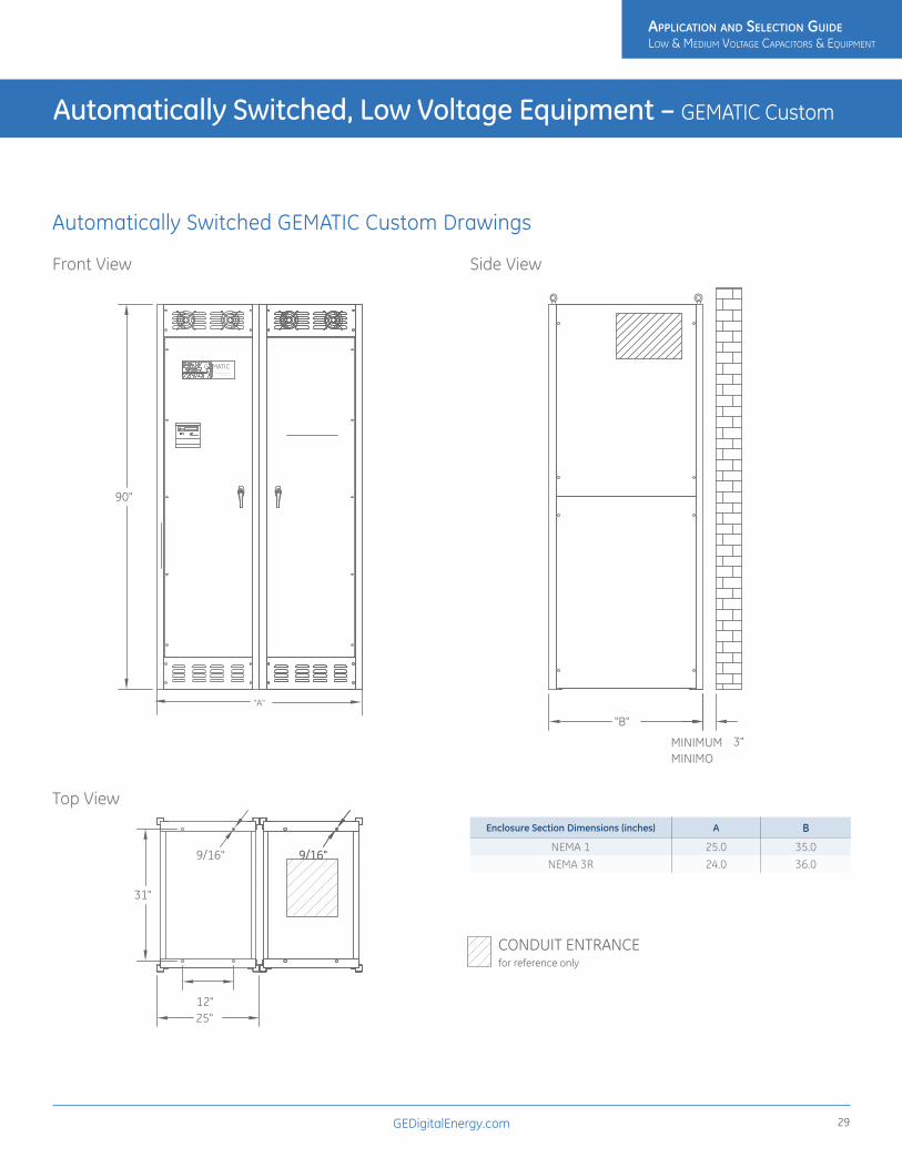
Enclosure Section Dimensions (inches) A B
NEMA 1 25.0 35.0NEMA 3R 24.0 36.0
Automatically Switched, Low Voltage Equipment – GEMATIC Custom
Automatically Switched GEMATIC Custom Drawings
Front View Side View
Top View9/16"
12"
90"
9/16"
31"
9/16"
11
Power Factor Controller A12
NOKIAN CAPACITORS
108 97
541 2 3
0.98&12
6
"A"
25"
"B"
MINIMUM 3"MINIMO
for reference onlyCONDUIT ENTRANCE
AH11
2
AH112
GEMATICCORRECTION SYSTEM
AUTOMATIC POWER FACTOR
9/16"
12"
90"
9/16"
31"
9/16"
11
Power Factor Controller A12
NOKIAN CAPACITORS
108 97
541 2 3
0.98&12
6
"A"
25"
"B"
MINIMUM 3"MINIMO
for reference onlyCONDUIT ENTRANCE
AH11
2
AH112
GEMATICCORRECTION SYSTEM
AUTOMATIC POWER FACTOR
9/16"
12"
90"
9/16"
31"
9/16"
11
Power Factor Controller A12
NOKIAN CAPACITORS
108 97
541 2 3
0.98&12
6
"A"
25"
"B"
MINIMUM 3"MINIMO
for reference onlyCONDUIT ENTRANCE
AH11
2
AH112
GEMATICCORRECTION SYSTEM
AUTOMATIC POWER FACTOR
9/16"
12"
90"
9/16"
31"
9/16"
11
Power Factor Controller A12
NOKIAN CAPACITORS
108 97
541 2 3
0.98&12
6
"A"
25"
"B"
MINIMUM 3"MINIMO
for reference onlyCONDUIT ENTRANCE
AH11
2
AH112
GEMATICCORRECTION SYSTEM
AUTOMATIC POWER FACTOR
ApplicAtion And Selection Guide Low & MediuM VoLtage CapaCitors & equipMent
ApplicAtion And Selection Guide Low & MediuM VoLtage CapaCitors & equipMent

GEDigitalEnergy.com30
GEMATIC Quick Response 480 volts 3 phase 60 Hz
Description• Ultra Fast Response (UFR): A real-time, transient-free system used to
compensate extremely rapid loads within one cycle (typically 5-16 mSec)
• Fast Response (FR): A fast , transient-free system, used to compensate any load within 3-4 seconds
Advantages • Ultra Fast Response (UFR) and Fast Response (FR)
• Transient-free capacitor group switching, using electronic switching elements
• Prevent damage to sensitive electronic equipment
• Saves energy
• Harmonic filtration
• Accurate power factor control, even in the presence of harmonics
• Dramatically increases the life expectancy of switching elements and capacitors
• Considerably lower temperature rise of capacitors and inductors due to unique scan feature
• Built-in three phase network analyzer, measuring all network parameters including harmonics
• Unique self-testing and comprehensive reporting feature
• Power IQ
• Ultra Fast Response (UFR) (in addition to the above):
• Cycle-by-cycle reactive power compensation (total acquisition time of 5-16 mSec)
• Prevents voltage drop and flickering
• Used for Real Time applications, such as spot welding and motor startup
• Enhances capacity of local generator systems, such as diesel and windmill generators
• Combination of one to three single-phase systems available for unbalanced loads
Note
GEMATIC Quick Response equipment is a specialized product for specific environments. Contact the factory for application and quoting assistance.
Automatically Switched, Low Voltage Equipment – GEMATIC Quick Response
ApplicAtion And Selection Guide Low & MediuM VoLtage CapaCitors & equipMent
ApplicAtion And Selection Guide Low & MediuM VoLtage CapaCitors & equipMent

GEDigitalEnergy.com 31
GEMActive Harmonic Filter
Product Information• Dynamic current injection for harmonic cancellation and power factor
correction
• Reduces harmonics for IEEE® 519 (1992) standard compliance
• Decreases harmonic related overheating of cables, switchgear and transformers
• Reduces downtime caused by nuisance thermal tripping of protective devices
• Increases electrical network reliability and reduces operating costs
• Compensates each phase independently
• UL and CSA approved
• Parallel connection allows for easy retrofit and installation of multiple units for large networks
• Filters to the 50th harmonic
• Filters entire network or specific loads depending on installation point
• Response to load fluctuations begins in 40 microseconds with 8 milliseconds for full response to step load changes
• IGBT based power electronic technology
• 50, 100 and 300A models for 208 to 480V, 50/60 Hz three phase networks
GE GEMActive reduces problematic harmonic levels and provides instantaneous power factor correction. Cost savings result from reduced downtime and maintenance. In addition, over-sizing of distribution equipment to provide for harmonics and poor power factor can be avoided. GE GEMActive dynamically corrects power quality by providing: Active Harmonic Filtration, Resonance Prevention, Power Factor Correction and Dynamic VAR Compensation.
The Harmonic ProblemAlthough power electronic loads and devices which have rapid and frequent load variations have become abundant due to their many process control related benefits, they have one major drawback in common: they produce harmonics. Harmonics may disrupt other loads and increase operating costs and lower the reliability of the electrical network. The current waveform required by power electronic loads is quite different than the sinusoidal voltage delivered by the utility. This ‘non-linear’ current draw (Figure 1) results in the creation of harmonics.
Symptoms of problematic harmonic levels include overheating of motors, drives, cables, thermal tripping of protective devices and logic faults of digital devices all of which can result in downtime. In addition the life span of many devices may be reduced by overheating. Furthermore, by reducing harmonic levels, the need to oversize transformers and cables to account for harmonic heating effects is lessened.
With this in mind, the IEEE 519-1992 recommended practice establishes limits on current distortion that individual facilities can feed back on to the utility grid. Many utilities enforce these limits and with the decrease in capital spending due to deregulation of the industry, many more utilities are expected to start to enforce these limits.
Automatic Low Voltage Harmonic Filter – GEMActive
Figure 1 – Non-linear Current
ApplicAtion And Selection Guide Low & MediuM VoLtage CapaCitors & equipMent
ApplicAtion And Selection Guide Low & MediuM VoLtage CapaCitors & equipMent

GEDigitalEnergy.com32
Active Harmonic Filtering with GEMActiveThe GE GEMActive cancels harmonics by dynamically injecting out of phase harmonic current. GEMActive installation will allow for compliance with IEEE 519 –1992 recommended harmonic limits. Reduced harmonic levels results in improved electrical network reliability and reduced operating costs. Nuisance tripping of protective devices and nuisance clearing of fuses due to harmonic heating effects is greatly reduced.
Overheating of motors, transformers, switchgear and cables is also reduced which increases their life expectancy and reduces maintenance costs. For new installations, over-sizing of distribution equipment to reduce harmonic susceptibility can be reconsidered.
GEMActive reduces current distortion that, in turn, reduces voltage distortion. Unlike passive devices, GEMActive is easy to install and cannot be overloaded. When required harmonic compensation exceeds capacity, GEMActive will simply supply its maximum continuously. Multiple GEMActive units can be connected in parallel to increase compensation.
Closed-loop control allows for high accuracy and self- adaptive harmonic control. GEMActive determines the harmonic compensation required by using current transformers to measure the network current. The GEMActive control logic removes the fundamental frequency component (50 or 60 Hz) from this waveform. The remaining waveform is then inverted and GEMActive fires its IGBTs to inject this waveform (Figure 2) on to the network to compensate for the harmonics. The result is a waveform with greatly reduced harmonic content as seen by the upstream electrical system (Figure 3).
The Resonance ProblemThe interconnection of a large variety of devices on today’s electrical networks can create resonant conditions which magnify harmonic currents (Figure 4). Resonance can cause serious problems such as excessive voltage distortion, nuisance fuse and circuit breaker operation, overvoltage tripping of drives, premature capacitor breakdown and insulation breakdown within motors, transformers and conductors.
GEMActive Eliminates ResonanceGE’s GEMActive cancels harmonic current on the network to eliminate resonance conditions. By dynamically removing harmonics from the network no energy is present at the resonant frequency. The point of installation of GEMActive on the electrical network determines where the harmonic cancellation takes place.
Automatic Low Voltage Harmonic Filter – GEMActive
Figure 2 – GEMActive Injection Current
Figure 4 – Circuit formed from Capacitor in Parallel with Source Impedance (Supply Transformer)
Figure 3 – Corrected current waveform
ApplicAtion And Selection Guide Low & MediuM VoLtage CapaCitors & equipMent
ApplicAtion And Selection Guide Low & MediuM VoLtage CapaCitors & equipMent

GEDigitalEnergy.com 33
Dynamic VAR Compensation by GEMActive Large inductive inrush currents typically cause voltage sags that result in reduced productivity, poor process quality and possible downtime due to undervoltage tripping of devices.
GE’s GEMActive is able to inject peak current at two and a half times its rms current rating for one cycle. For many applications this level of compensation eliminates visible flicker and improves voltage regulation resulting in better productivity and quality.
GEMActive SizingA harmonic study is not required to select the size of the GEMActive installation. This is because when GEMActive is installed it becomes a lower impedance path for harmonics than the existing power supply. For sizing, please contact General Electric. To expedite the product selection process, please have a single line diagram and/or details of the application including sizes of transformers, non-linear and linear loads, and any existing filters and capacitors.
Automatic Low Voltage Harmonic Filter – GEMActive
Figure 5 – Non-linear current waveform with poor power factor Figure 7 – Inrush current without GEMActive installed
Figure 8 – Inrush current with GEMActive installedFigure 6 – Corrected current waveform with improved power factor and reduced harmonic current after installing GEMActive
GEMActive Harmonic Filter
ApplicAtion And Selection Guide Low & MediuM VoLtage CapaCitors & equipMent
ApplicAtion And Selection Guide Low & MediuM VoLtage CapaCitors & equipMent

GEDigitalEnergy.com34
GEMTRAP240 - 480 - 600 volts 3 phase 60 Hz
Product Information:• Three-phase, 60Hz
• 240, 480, 600 Volts
• NEMA 1 Enclosure
• Normally tuned for the 4.7th Harmonic
• Can be tuned to any desired frequency. Contact factory for more information.
• Note: Do not apply Harmonic Filters without a detailed analysis of the power system.
ApplicationThe proliferation of electronic equipment used to improve efficiencies and provide more reliable performance causes harmonics on power systems. Equipment such as variable speed AC and DC drives, uninterruptible power supplies, switching power supplies and other solid state controls or devices inject non-linear components into what was a linear system. The application of power factor correction capacitor systems can create unwanted increases in harmonic voltage and current unless the capacitors are properly applied with reactors, in series with the capacitor, to suppress harmful harmonics.
GE’s line of fixed harmonic suppression capacitors permits the installation of power factor correction capacitors on systems with nonlinear components. The GEMTRAP system can be tuned to any desired frequency but is normally tuned to the fifth harmonic.
DesignThe installation of this system is application specific. Contact the GE Sales office or the factory to ensure that the proper combination of capacitors and reactors is used. Misapplication may result without proper guidance.
StandardsNEMA, IEEE/ANSI, NEC
Ratings• 240V, 5 to 60 kVAR-3 ph
• 480 V. 5 to 200 kVAR-3 ph
• 600 V; 10 to 200 kVAR-3ph
Equipment Construction• Enclosure and wiring hood: Indoor/outdoor gasketed heavy gauge steel.
Finished with a zinc rich primer and an ANSI #70, enamel overcoat. Louvered panels around reactors for protection and cooling.
• Mounting: Floor mounting.
• Capacitor Fuses: UL recognized, designed specifically for capacitor applications. Rated 600 VAC; 200kAIC. Fast acting and current limiting; provide protection from catastrophic failures. Three phase fusing standard.
• Aluminum Connecting Bus for Parallel Cells
• Input Connections: Listed Cu/AI Mechanical wire connectors, sized for KVAR requirements, mounted on top of bus for easy access.
• Harmonic Reactor
Options• Blown fuse lights.
• Consult factory for larger kVAR requirements.
• Consult factory for custom applications
Fixed Low Voltage Harmonic Filter – GEMTRAP
ApplicAtion And Selection Guide Low & MediuM VoLtage CapaCitors & equipMent
ApplicAtion And Selection Guide Low & MediuM VoLtage CapaCitors & equipMent

GEDigitalEnergy.com 35
GEMTRAP Filters – 240- 480- 600 Volts – 3 Phase- 60 Hz
Volts kVARBase Catalog Number
(add L to the end for blown fuse lights)
Capacitors w/Reactor & 3-Fuses
Drawing
Approximate Weight
(lbs)
240 25 38FH1025D333F 1 195
35 38FH2035D333F 2 341
40 38FH2040D333F 2 346
45 38FH2045D333F 2 351
50 38FH2050D333F 2 356
480 25 38FH1025F333F 1 159
30 38FH1030F333F 1 191
40 38FH1040F333F 1 197
50 38FH1050F333F 1 202
75 38FH1075F333F 1 235
80 38FH1080F333F 1 263
100 38FH1100F333F 1 279
120 38FH2120F333F 2 424
125 38FH2125F333F 2 447
140 38FH2140F333F 2 500
150 38FH2150F333F 2 514
175 38FH2175F333F 2 524
200 38FH2200F333F 2 568
600 25 38FH1025H333F 1 159
30 38FH1030H333F 1 191
40 38FH1040H333F 1 196
50 38FH1050H333F 1 196
75 38FH1075H333F 1 245
80 38FH1080H333F 1 248
100 38FH1100H333F 1 271
120 38FH2120H333F 2 484
125 38FH2125H333F 2 487
140 38FH2140H333F 2 495
150 38FH2150H333F 2 500
175 38FH2175H333F 2 526
200 38FH2200H333F 2 552
Fixed Low Voltage Harmonic Filter – GEMTRAP
ApplicAtion And Selection Guide Low & MediuM VoLtage CapaCitors & equipMent
ApplicAtion And Selection Guide Low & MediuM VoLtage CapaCitors & equipMent

GEDigitalEnergy.com36
Fixed Low Voltage Harmonic Filter – GEMTRAP
GEMTRAP Fixed Filters Drawings
Figure 1
Figure 2
19.75
20.00
17.50
11.13
14.5
17.00
37.00
22.75
23.75
20.37
10.27
11.10
10.85
4.94
5.0
2.78
4.38
14.5
17.0
ApplicAtion And Selection Guide Low & MediuM VoLtage CapaCitors & equipMent
ApplicAtion And Selection Guide Low & MediuM VoLtage CapaCitors & equipMent

GEDigitalEnergy.com 37
Line/Load Reactors Up to 600 Volts
Motor Protection Reactors help to protect motors from the high peak voltages and fast rise times (dv/dt) which can be experienced in IGBT inverter applications when the distance between the inverter and motor is long.
Harmonic Reduction Because all standard GE Line/Load reactors are compensated for harmonics (current and frequency), they are extremely effective at reducing the amount of harmonics which are produced by a drive/inverter. Use 5% impedance, harmonic compensated reactors for best reaction of harmonic distortion.
Voltage Spike Protection A 3% impedance reactor is very effective at protecting against damage to or nuisance tripping of AC voltage source inverters, due to voltage spikes. Voltage spikes on the AC power lines cause elevation of the DC Bus voltage which may cause the inverter to “trip-off” and indicate an over-voltage protection condition. Use reactors to absorb these line spikes and offer protection to the rectifiers and DC Bus capacitors while minimizing nuisance tripping of the inverter.
Agency Approvals• GE line reactors are UL recognized.
• All UL approvals are for USA and Canada.
• UL-506 File #E191687 (1 amp-1200 amps)
• UL-508 File #E191686 (1 amp-1200 amps)
• All higher currents offer UL recognized insulation systems and construction.
• CE Marked
NEMA 1 Cabinets All GE Line/Load Reactors are available as either open type or in a NEMA Type 1 general purpose enclosure. To order a reactor mounted in a cabinet simply change the second to last digit of the product number from “0” to “1”. Example 37G 00802 becomes 37G 00812.
Low Voltage – Line/Load Reactors
Figure 1 – Typical Distortion of PWM Inverter without Reactor
Figure 2 – Typical Distortion of PWM Inverter With 5% Reactor applied
Figure 3 – NEMA 1 Cabinets
ApplicAtion And Selection Guide Low & MediuM VoLtage CapaCitors & equipMent
ApplicAtion And Selection Guide Low & MediuM VoLtage CapaCitors & equipMent

GEDigitalEnergy.com38
Low Voltage – Line/Load Reactors
VOLTAGE, 50/60 HZ
% IMPEDANCE CATALOG NUMBER
Ratings HP/kW 1.0/0.75 1.5/1.1 2.0/1.5 3.0/2.2 5.0/3.7 7.5/5.5 10/7.5 15/11 20/15 25/18.5 30/22 40/30
208 3% 37G00401 37G00801 37G00801 37G01201 37G00801 37G02501 37G03501 37G04501 37G05501 37G08001 37G10001 37G130015% 37G00402 37G00802 37G00802 37G01202 37G00802 37G02502 37G03502 37G04502 37G05502 37G08002 37G10002 37G13002
240 3% 37G00401 37G00801 37G00801 37G01201 37G00801 37G02501 37G03501 37G04501 37G05501 37G08001 37G10001 37G130015% 37G00402 37G00802 37G00802 37G01202 37G00802 37G02502 37G03502 37G04502 37G05502 37G08002 37G10002 37G13002
380 2% 37G00204 37G00402 37G00401 37G00802 37G00801 37G01201 37G01801 37G02501 37G03501 37G04501 37G04501 37G080014% 37G00201 37G00404 37G00402 37G00803 37G00802 37G01202 37G01802 37G02502 37G03502 37G04502 37G04502 37G08002
400 2% 37G00201 37G00402 37G00402 37G00802 37G00801 37G01201 37G01801 37G02501 37G03501 37G04501 37G04501 37G055014% 37G00202 37G00404 37G00403 37G00803 37G00802 37G01202 37G01802 37G02502 37G03502 37G04502 37G04502 37G05502
415 2% 37G00201 37G00402 37G00402 37G00802 37G00801 37G01201 37G01801 37G02501 37G03501 37G04501 37G04501 37G055014% 37G00202 37G00404 37G00403 37G00803 37G00802 37G01202 37G01802 37G02502 37G03502 37G04502 37G04502 37G05502
480 3% 37G00201 37G00201 37G00402 37G00402 37G00802 37G01202 37G01802 37G02502 37G03502 37G03502 37G04502 37G055025% 37G00202 37G00202 37G00403 37G00403 37G00803 37G01203 37G01803 37G02503 37G03503 37G03503 37G04503 37G05503
600 3% 37G00202 37G00202 37G00403 37G00403 37G00803 37G00802 37G01202 37G01802 37G02502 37G02502 37G03502 37G045025% 37G00203 37G00203 37G00404 37G00404 37G00804 37G00803 37G01203 37G01803 37G02503 37G02503 37G03503 37G04503
For maximum continuous current ratings refer to Specifications on following page
VOLTAGE, 50/60 HZ
% IMPEDANCE CATALOG NUMBER
Ratings HP/kW 50/37.5 60/45 75/55 100/75 125/93 150/112 200/150 250/187 300/225 350/262 400/300 500/375 600/450 750/550208 3% 37G 16001 37G 20001B14 37G 25001B14 37G 32001B14 37G 40001B14 37G 50001 37G 60001 37G 75001 • • • • • •
5% 37G 16002 37G 20002B14 37G 25021B14 37G 32002B14 37G 40002B14 37G 50002 37G 60002 37G 75002 • • • • • •
240 3% 37G 13001 37G 16001 37G 20001B14 37G 25001B14 37G 32001B14 37G 40001B14 37G 50001 37G 60001 37G 75001 • • • • •
5% 37G 13002 37G 16002 37G 20002B14 37G 25021B14 37G 32002B14 37G 40002B14 37G 50002 37G 60002 37G 75002 • • • • •
380 2% 37G 08001 37G 10001 37G 10001 37G 16001 37G 20001B14 37G 25001B14 37G 32001B14 37G 40001B14 37G 40001B14 37G 75001 37G 60001 37G 75002 • •
4% 37G 08002 37G 10002 37G 10002 37G 16002 37G 20001B14 37G 25001B14 37G 32001B14 37G 40001B14 37G 40001B14 37G 75002 37G 60002 37G 75003 • •
400 2% 37G 08001 37G 08001 37G 10001 37G 13001 37G 20002B14 37G 25002B14 37G 32002B14 37G 32001B14 37G 40001B14 37G 50001 37G 50002 37G 75002 • •
4% 37G 08002 37G 08002 37G 10002 37G 13002 37G 20003B14 37G 25003B14 37G 32003B14 37G 32002B14 37G 40002B14 37G 50002 37G 60003 37G 75003 • •
415 2% 37G 08001 37G 08001 37G 10001 37G 13001 37G 20002B14 37G 20002B14 37G 25001B14 37G 32001B14 37G 40001B14 37G 50001 37G 50001 37G 75002 37G 75002 •
4% 37G 08002 37G 08002 37G 10002 37G 13002 37G 20003B14 37G 20003B14 37G 25002B14 37G 32002B14 37G 40002B14 37G 50002 37G 50002 37G 75003 37G 75003 •
480 3% 37G 08002 37G 08002 37G 10002 37G 13002 37G 16002 37G 20002B14 37G 25002B14 37G 32002B14 37G 40002B14 37G 50002 37G 50002 37G 60002 37G 75002 •
5% 37G 08003 37G 08003 37G 10003 37G 13003 37G 16003 37G 20003B14 37G 25003B14 37G 32003B14 37G 40003B14 37G 50003 37G 50003 37G 60003 37G 75003 •
600 3% 37G 05502 37G 08002 37G 08002 37G 10002 37G 13002 37G 16002 37G 20002B14 37G 20002B14 37G 32002B14 37G 40002B14 37G 40002B14 37G 50002 37G 60002 37G 75002
5% 37G 05503 37G 08003 37G 08003 37G 10003 37G 13003 37G 16003 37G 20003B14 37G 20003B14 37G 32003B14 37G 40003B14 37G 40003B14 37G 50003 37G 60003 37G 75003
• Consult Factory
* This table is suitable for selection of both input and output reactors because their harmonic compensation and IGBT protection allow them to be used in either application. Specific current and inductance ratings are indicated on the next page. Consult factory for any special applications (higher current, motor ratings different than the controller ratings, etc).
Select GE Line/Load reactors based upon motor horsepower, (or kilowatts) and voltage. Verify that the motor full load ampere rating is within the fundamental ampere current rating of the reactor, and the drive/inverter is within the maximum continuous rating of the reactor. (See next page)
Selection Table*, 600 Volts, 50/60 Hertz (open frame type reactor)
ApplicAtion And Selection Guide Low & MediuM VoLtage CapaCitors & equipMent
ApplicAtion And Selection Guide Low & MediuM VoLtage CapaCitors & equipMent

GEDigitalEnergy.com 39
Low Voltage – Line/Load Reactors
Open Frame
Catalog Number
Fund. Amps Max. Amps Inductance (mh)
Watts Loss
A mm/in
B mm/in
C mm/in
D mm/in
E mm/in
Open Type Weight kg/lbs
NEMA 1 Encl. Style1
37G00201 2 3 12.0 7.5 112/4.4 102/4.0 74/2.8 50/2.0 36/1.44 1.8/4 CAB-8
37G00202 2 3 20.0 11.3 112/4.4 102/4.0 74/2.9 50/2.0 36/1.44 1.8/4 CAB-8
37G00203 2 3 32.0 16 112/4.4 102/4.0 74/2.9 50/2.0 36/1.44 1.8/4 CAB-8
37G00204 2 3 6.0 10.7 112/4.4 102/4.0 69/2.7 44/1.73 36/1.44 1.4/3 CAB-8
37G00401 4 6 3.0 14.5 112/4.4 102/4.0 74/2.9 50/2.0 36/1.44 1.8/4 CAB-8
37G00402 4 6 6.5 20 112/4.4 102/4.0 74/2.9 50/2.0 36/1.44 2.3/4 CAB-8
37G00403 4 6 9.0 20 112/4.4 102/4.0 79/3.1 54/2.1 36/1.44 1.8/5 CAB-8
37G00404 4 6 12.0 21 112/4.4 102/4.0 91/3.6 66/2.6 36/1.44 2.7/6 CAB-8
37G00801 8 12 1.5 19.5 152/6.0 122/4.8 79/3.1 54/2.1 50/2.0 3.1/7 CAB-8
37G00802 8 12 3.0 29 152/6.0 122/4.8 79/3.1 54/2.1 50/2.0 3.2/8 CAB-8
37G00803 8 12 5.0 25.3 152/6.0 122/4.8 86/3.4 63/2.5 50/2.0 5.0/11 CAB-8
37G00804 8 12 7.5 28 152/6.0 122/4.8 86/3.4 63/2.5 50/2.0 5.9/13 CAB-8
37G01201 12 18 1.25 26 152/6.0 122/4.8 79/3.1 54/2.1 50/2.0 4.0/9 CAB-8
37G01202 12 18 2.5 31 152/6.0 122/4.8 79/3.1 54/2.1 50/2.0 4.5/10 CAB-8
37G01203 12 18 4.2 41 152/6.0 122/4.8 94/3.7 70/2.75 50/2.0 8.1/18 CAB-8
37G01801 18 27 0.8 36 152/6.0 122/4.8 79/3.1 54/2.1 50/2.0 4.0/9 CAB-8
37G01802 18 27 1.5 43 152/6.0 122/4.8 86/3.4 53/2.5 50/2.0 5.4/12 CAB-8
37G01803 18 27 2.5 43 183/7.2 145/5.7 97/3.8 66/2.6 76/3.0 7.3/16 CAB-13V
37G02501 25 37.5 0.5 48 183/7.2 142/5.6 86/3.4 60/2.3 76/3.0 5.0/11 CAB-13V
37G02502 25 37.5 1.2 52 183/7.2 142/5.6 86/3.4 60/2.3 76/3.0 6.3/14 CAB-13V
37G02503 25 37.5 0.8 61 183/7.2 145/5.7 97/3.8 66/2.6 76/3.0 8.1/18 CAB-13V
37G03501 35 52.5 0.4 49 183/7.2 142/5.6 97/3.8 66/2.6 76/3.0 6.3/14 CAB-13V
37G03502 35 52.5 0.8 54 183/7.2 145/5.7 97/3.8 66/2.6 76/3.0 7.3/16 CAB-13V
37G03503 35 52.5 1.2 54 229/9.0 178/7.0 122/4.8 80/3.2 76/3.0 14/30 CAB-13V
37G04501 45 67.5 0.3 54 229/9.0 178/7.0 122/4.8 80/3.2 76/3.0 10/23 CAB-13V
37G04502 45 67.5 0.7 62 229/9.0 178/7.0 122/4.8 80/3.2 76/3.0 13/28 CAB-13V
37G04503 45 67.5 1.2 65 229/9.0 178/7.0 136/5.3 93/3.6 76/3.0 18/39 CAB-13V
37G05501 55 82.5 0.26 64 229/9.0 178/7.0 122/4.8 80/3.2 76/3.0 11/24 CAB-13V
37G05502 55 82.5 0.50 67 229/9.0 178/7.0 122/4.8 80/3.2 76/3.0 12/27 CAB-13V
37G05503 55 82.5 0.85 71 229/9.0 178/7.0 142/5.6 99/3.9 76/3.0 18/41 CAB-13V
37G08001 80 120 0.20 82 274/10.8 208/8.2 142/5.6 88/3.5 92/3.6 19/43 CAB-13V
37G08002 80 120 0.40 86 274/10.8 211/8.3 142/5.6 88/3.5 92/3.6 23/51 CAB-13V
37G08003 80 120 0.70 96 274/10.8 213/8.4 160/6.3 117/4.6 82/3.6 25/55 CAB-13V
1 To order a reactor in a NEMA 1 enclosure, change the 7th digit in the part number from “0” to “1”.
3 Phase Line/Load Reactor Specification Table 600 Volt , 50/60 Hertz (open frame type reactor)
ApplicAtion And Selection Guide Low & MediuM VoLtage CapaCitors & equipMent
ApplicAtion And Selection Guide Low & MediuM VoLtage CapaCitors & equipMent

GEDigitalEnergy.com40
Low Voltage – Line/Load Reactors
Open Frame Catalog Number
Fund. Amps Max. Amps Inductance
(mh)Watts Loss
A mm/in
B mm/in
C mm/in
D mm/in
E mm/in
Open Type Weight kg/lbs
NEMA 1 Encl. Style1
37G10001 100 150 0.15 94 274/10.8 211/8.3 142/5.6 88/3.5 92/3.6 21/47 CAB-13V
37G10002 100 150 0.30 84 274/10.8 208/8.2 147/5.8 93/3.6 92/3.6 23/51 CAB-13V
37G10003 100 150 0.45 108 274/10.8 213/8.4 160/6.3 106/4.2 92/3.6 33/74 CAB-13V
37G13001 130 195 0.10 108 229/9.0 179/7.04 124/4.9 80/3.16 76/3 13/29 CAB-13V
37G13002 130 195 0.20 180 274/10.8 213/8.4 171/6.75 93/3.66 92/3.63 26/57 CAB-13V
37G13003 130 195 0.30 128 274/10.8 213/8.4 184/7.25 106/4.16 92/3.63 29/64 CAB-13V
37G16001 160 240 0.075 116 274/10.8 213/8.4 146/5.75 80/3.16 92/3.63 18/40 CAB-13V
37G16002 160 240 0.150 149 274/10.8 213/8.4 152/6 88/3.47 92/3.63 22/50 CAB-13V
37G16003 160 240 0.230 138 274/10.8 213/8.4 181/7.13 106/4.16 92/3.63 31/67 CAB-13V
37G20001B14 200 300 0.055 124 274/10.8 213/8.4 152/6 106/4.16 92/3.63 22/48 CAB-13V
37G20002B14 200 300 0.110 168 274/10.8 213/8.4 216/8.5 112/4.41 92/3.63 31/67 CAB-13V
37G20003B14 200 300 0.185 146 274/10.8 267/10.5 237/9.35 150/5.91 92/3.63 46/100 CAB-13V
37G25001B14 250 375 0.045 154 274/10.8 208/8.17 184/7.25 106/4.16 92/3.63 31/68 CAB-13V
37G25002B14 250 375 0.090 231 366/14.4 356/14 210/8.25 131/5.16 117/4.6 49/106 CAB-17V
37G25003B14 250 375 0.150 219 366/14.4 356/14 288/11.35 148/5.82 117/4.6 64/140 CAB-17V
37G32001B14 320 480 0.040 224 366/14.4 356/14 168/6.6 129/5.07 117/4.6 50/110 CAB-17V
37G32002B14 320 480 0.075 264 375/14.75 356/14 257/10.13 149/5.88 117/4.6 57/125 CAB-17V
37G32003B14 320 480 0.125 351 366/14.4 356/14 330/13 181/7.13 117/4.6 86/190 CAB-17V
37G40001B14 400 600 0.030 231 366/14.4 356/14 254/10 131/5.16 117/4.6 46/100 CAB-17V
37G40002B14 400 600 0.060 333 394/15.5 356/14 292/11.5 172/6.76 117/4.6 71/155 CAB-17V
37G40003B14 400 600 0.105 293 394/15.5 356/14 368/14.5 184/7.26 117/4.6 91/200 CAB-17V
37G50001B14 500 750 0.025 266 394/15.5 356/14 267/10.5 140/5.5 117/4.6 55/120 CAB-17V
37G50002 500 750 0.050 340 394/15.5 356/14 330/13 172/6.76 117/4.6 82/180 CAB-1726C
37G50003 500 700 0.085 422 394/15.5 356/14 375/14.75 248/9.76 117/4.6 132/290 CAB-1726C
37G60001 600 900 0.020 307 394/15.5 356/14 279/11 168/6.66 117/4.6 73/160 CAB-1726C
37G60002 600 900 0.040 414 394/15.5 356/14 356/14 172/6.76 117/4.6 96/210 CAB-1726C
37G60003 600 840 0.065 406 394/15.5 356/14 394/15.5 235/9.26 117/4.6 132/290 CAB-1726C
37G75001 750 1125 0.015 427 559/22 508/20 254/10 168/6.63 183/7.2 91/200 CAB-30B26C
37G75002 750 1125 0.029 630 559/22 508/20 317/12.5 197/7.76 183/7.2 141/310 CAB-30B26C
37G75003 750 1125 0.048 552 559/22 508/20 376/14.8 242/9.51 183/7.2 183/400 CAB-30B26C
1 To order a reactor in a NEMA 1 enclosure, change the 7th digit in the part number from “0” to “1”.
3 Phase Line/Load Reactor Specification Table 600 Volt , 50/60 Hertz (open frame type reactor)
ApplicAtion And Selection Guide Low & MediuM VoLtage CapaCitors & equipMent
ApplicAtion And Selection Guide Low & MediuM VoLtage CapaCitors & equipMent

GEDigitalEnergy.com 41
Matrix Broadband Harmonic Filters
DescriptionMatrix Harmonic filters provide broadband reduction of harmonics. Matrix Harmonic Filters not only offer better performance over other broad band filtering and 18-pulse harmonic reduction techniques, they are also suitable for a wider range of applications. Matrix Harmonic Filters can be installed in either variable or constant torque drive applications and can be applied on either diode or SCR rectifiers. For any application other than variable torque applications, it is suggested that you contact the factory for filter selection.
Typical Applications Use Matrix Harmonic filters to minimize harmonic current distortion in these and other 6-pulse rectifier applications:
Matrix Filter enables most AC drive systems to comply with the voltage and current distortion limits outlined in IEEE 519. A complete harmonic analysis and product selection tool is available on the internet. Go to geelectrical.com and select Products, select Capacitors, choose Matrix Harmonic Filter and then select Energy Savings Calculator and Harmonic Estimator.
Matrix Harmonic Filters are multi-stage low pass filters specially configured to avoid the attraction of harmonics from other sources on a shared power system. Matrix filters will not cause power system resonance. However, the configuration of the filter requires that only drives or equivalent loads be loaded on the output of a Matrix harmonic filter. One filter can be used with multiple drives. However, if there is a drive bypass circuit, there must be one filter per drive and the filter and drive combination must be bypassed.
Matrix Harmonic Filters are available in a NEMA 1, NEMA 3R or as a modular design preassembled onto panels for subsequent assembly into customer supplied cabinet.
Product Specifications • Input Voltage 480 Volts +/– 10%
• Ambient Temperature:
• Storage – 40°C to 90°C
• Operating – 40°C to 40°C
• Altitude: 1000 meters maximum
• UL approved – File E191686 for U.S. and Canada
Minimum System Requirements to Achieve Performance Levels• Source Impedance: 1.5% minimum to 5% maximum
• System voltage: 480 volts (line to line) +/– 10%
• Frequency: 60 Hz +/– .75 Hz
• Balanced Line Voltage: within 1%
• Background Voltage Distortion: 0% THVD
The Matrix D Filters typically achieve 5% THID at full load and guarantee worst case current distortion at any load between 0% and 100%, will be 8% THID or less at the filter input terminals. The Matrix D Series is typically used in place of applications requiring harmonic mitigation associated with 12- or 18-pulse rectifiers.
The chart below compares the performance of Matrix D Filters to 18-pulse rectifiers in real world applications, which include line voltage unbalance of 1% to 3% and loading conditions from 0% to 100%.
Matrix D Filter performs better than 18-pulse in normal operating conditions.
SelectionSelect Matrix filters based on the horsepower (or kilowatt) rating for the adjustable speed drive or the combined current rating of all motors to be connected to the load side of the filter.
For constant torque, DC drive or other applications consult factory for proper filter selection.
Source Impedance If the source impedance is less than 1.5% impedance, it is required that an input reactor of at least 1.5% impedance be added in order to have guaranteed performance level.
For best value and performance it is recommended that a 3% line reactor be used whenever the source impedance is less than 1.5%.
• Fans and Pumps
• Water Treatment Facilities
• HVAC Systems
• AC or DC Motor Drives
• Rectifier type welders
• Induction Heating Equipment
• UPS Equipment
• Elevators
Low Voltage – Matrix Broadband Harmonic Filters
ApplicAtion And Selection Guide Low & MediuM VoLtage CapaCitors & equipMent
ApplicAtion And Selection Guide Low & MediuM VoLtage CapaCitors & equipMent

GEDigitalEnergy.com42
Function of CapacitorsElectric power has two components:
• Active power, which produces work.
• Reactive power, which is needed to generate magnetic fields required for operation of inductive electrical equipment, but performs no useful work.
Active power is measured in KW (1000 Watts)
Reactive power is measured in KVAR (1000 Volt-Amperes Reactive) Total power is measured in KVA (1000 Volts-Amperes) The ratio of working power to totaI power is called Power Factor. The function of Power Factor Correction Capacitors is to increase the power factor by supplying the reactive power when installed at or near inductive electrical equipment.
Equipment Causing Poor Power FactorA great deal of equipment causes poor power factor. One of the worst offenders is lightly loaded induction equipment. Examples of this type of equipment, and their approximate power factors follow:
• 80% power factor or better: Air conditioners (correctly sized),pumps, centerless grinders, cold headers, upsetters, fans or blowers.
• 60% to 80% power factor: Induction furnaces, standard stamping machines, and weaving machines.
• 60% power factor and below: Single-stroke presses, automated machine tools, finish grinders, welders. When the above equipment functions within a facility, savings can be achieved by utilizing GE industrial capacitors.
How Capacitors Save MoneyCapacitors lower electrical costs two ways: In many areas, the electrical rate includes a penalty charge for low power factor. Installation of power capacitors on the electrical distribution system within a facility makes it unnecessary for the utility to supply the reactive power required by inductive electrical equipment. The savings the utility realizes in reduced generation, transmission, and distribution costs are passed on to the customer in the form of lower electrical bills.
The second source of savings derived through the use of power factor correction capacitors is in the form of increased KVA capacity in the electrical distribution system. Installation of capacitors to furnish the non-productive current requirements of the facility makes it possible to increase the connected load by as much as 20 percent without a corresponding increase in the size of the transformers, conductors, and protective devices making up the distribution system which services the load.
Aids for Application – Power Factor Capacitors & Harmonic Filters
The figure above shows an induction motor operating under partially loaded conditions without Power Factor Correction. Here the feeder line must supply BOTH magnetizing (reactive) and active power.
The figure above shows the result of installing a capacitor near the same motor to supply the reactive power required to operate it . The total current requirement has been reduced to the value of the active power only, thus either reducing power cost or permitting the use of more electrical equipment on the same circuit .
ApplicAtion And Selection Guide Low & MediuM VoLtage CapaCitors & equipMent
ApplicAtion And Selection Guide Low & MediuM VoLtage CapaCitors & equipMent
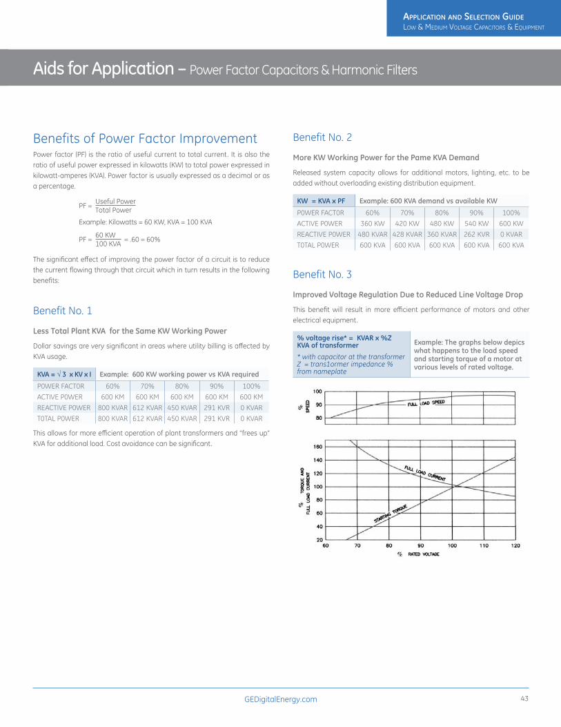
GEDigitalEnergy.com 43
Benefits of Power Factor ImprovementPower factor (PF) is the ratio of useful current to total current. It is also the ratio of useful power expressed in kilowatts (KW) to total power expressed in kilowatt-amperes (KVA). Power factor is usually expressed as a decimal or as a percentage.
The significant effect of improving the power factor of a circuit is to reduce the current flowing through that circuit which in turn results in the following benefits:
Benefit No. 1
Less Total Plant KVA for the Same KW Working Power
Dollar savings are very significant in areas where utility billing is affected by KVA usage.
KVA = √ 3 x KV x I Example: 600 KW working power vs KVA required
P0WER FACT0R 60% 70% 80% 90% 100%ACTIVE P0WER 600 KM 600 KM 600 KM 600 KM 600 KMREACTIVE P0WER 800 KVAR 612 KVAR 450 KVAR 291 KVR 0 KVART0TAL P0WER 800 KVAR 612 KVAR 450 KVAR 291 KVR 0 KVAR
This allows for more efficient operation of plant transformers and “frees up” KVA for additional load. Cost avoidance can be significant.
Benefit No. 2
More KW Working Power for the Pame KVA Demand
Released system capacity allows for additional motors, lighting, etc. to be added without overloading existing distribution equipment.
KW = KVA x PF Example: 600 KVA demand vs available KW
P0WER FACT0R 60% 70% 80% 90% 100%ACTIVE P0WER 360 KW 420 KW 480 KW 540 KW 600 KWREACTIVE P0WER 480 KVAR 428 KVAR 360 KVAR 262 KVR 0 KVART0TAL P0WER 600 KVA 600 KVA 600 KVA 600 KVA 600 KVA
Benefit No. 3
Improved Voltage Regulation Due to Reduced Line Voltage Drop
This benefit will result in more efficient performance of motors and other electrical equipment.
% voltage rise* = KVAR x %Z KVA of transformer
* with capacitor at the transformer Z = trans1ormer impedance % from nameplate
Example: The graphs below depics what happens to the load speed and starting torque of a motor at various levels of rated voltage.
PF = Useful Power
Total Power
PF = 60 KW
100 KVA = .60 = 60%
Example: Kilowatts = 60 KW, KVA = 100 KVA
Aids for Application – Power Factor Capacitors & Harmonic Filters
ApplicAtion And Selection Guide Low & MediuM VoLtage CapaCitors & equipMent
ApplicAtion And Selection Guide Low & MediuM VoLtage CapaCitors & equipMent

GEDigitalEnergy.com44
Benefit No. 4
Reduction in Size of Transformers, Cables and Switchgear in New Installations – Thus Less Investment
I = KVA x 103 √3 V
Example: The figure below represents the increasing size of conductors required to carry the same 100 KW at various power factors.
Benefit No. 5
Reduced Power Losses in Distribution Systems
Since the losses are proportionate to the square of the current, the formula at left applies.
% Reduction of Power Losses= 100-100 = [original PF] 2 New PF
Example: Improve powerfactor from 65% to 90%
Facts and Formulas
De-rating for V & f
KVARE = KVARR (VA2)(fA) VR fR
KVARE = Effective KVARKVARR = Rated KVARVA = Applied VoltageVR = Rated VoltagefA = Applied frequencyfR = Rated frequency
Aids for Application – Power Factor Capacitors & Harmonic Filters
ApplicAtion And Selection Guide Low & MediuM VoLtage CapaCitors & equipMent
ApplicAtion And Selection Guide Low & MediuM VoLtage CapaCitors & equipMent

GEDigitalEnergy.com 45
Degree of Power Factor ImprovementAs noted on page 49, power capacitors lower costs two ways. To determine how much improvement should be made to the existing power factor, one must analyze the potential benefits to be gained in each situation. If utility bill savings are a factor, it is recommended that the past 12 months’ billings be reviewed and compared to potential billings at improved power factor levels. Since there are a variety of rate structures in existence, each case must be investigated separately. In general, where penalty clauses exist, the power factor should be raised to at least 95 percent.
Where relief of an overloaded distribution system is the major consideration, the degree of correction will depend upon the amount of relief required. In some instances, correction to unity may be economical.
Size of Capacitor BankWhere the size of the capacitor bank needed to improve power factor to the desired level (usually 95%) is not readily available from Motor Tables or by graphic determination, it can be calculated as shown on page 54 or by these formulae.
TO FIND WHEN YOU KNOW THREE–PHASE
Watts input to anything Output, efficiency Watts output %
efficiency
Watts input to a motor Horsepower, efficiency
hp x ,746 x LF% efficiency
Horsepower PF (Output)
Current, voltage efficiency, power factor
1.73 x E x I x %eff, x
.746
Kilovolt-amperes Current, voltage1.73 x E x I
1000
Kilowatts Current, voltage, power factor
1.73 x E x I x PF1000
Amperes Horsepower, voltage, efficiency, power factor
hp x .746 x LF1.73 x E x %eff,
x PF
Amperes Kilowatts, voltage, power factor
kw x 10001.73 x E x PF
Amperes Kilovolt-amperes, voltage
kva x 10001.73 x E
Power factor Watts, voltage, current
Watts1,73 x E x I
Power factor Kilowatts, voltage, current
kw x 10001.73 x E x I
PF = power factor E = volts LF = load factor I = current in amperes
Determining Your Capacitor RequirementsThe total KVAR rating of capacitors required to improve a facility’s power factor to any desired value may be calculated very easily by using several basic formulas and by applying the appropriate multiplier selected from Table 1 on page 54.
Examples:1. A plant with a metered demand of 600 KW is operating at a 75% power
factor. What capacitor KVAR is required to correct the present power factor to 95%?
a. From Table 1, Multiplier to improve PF from 75% to 95% is .553
b. Capacitor KVAR = KW x Table 1 Multiplier Capacitor KVAR = 600 x .553 = 331.8 say 330
2. A plant load of 425 KW has a total power requirement of 670 KVA. What size capacitor is required to improve the factor to 90%?
a. Present PF = a. Present PF = KW = 425= .634 = 63.4% say 63% KVA 670
b. From Table 1, Multiplier to improve PF from 63% to 90% is .748
c. Capacitor KVAR = KW x Table 1 Multiplier = 425 x .748 = 317.9 say 320 KVAR
3. A plant operating from a 480 volt system has a metered demand of 258 KW. The line current read by a clip-on ammeter is 420 amperes. What amount of capacitor kVAR is required to correct the present power factor to 90%?
a. KVA = 1.73 x KV x I = 1.73 x .480 x 420 = 349 KVA
a. Present PF = KW = 258 = 73.9 say 74% KVA KVA 349
b. From Table 1, Multiplier to improve PF from 74% to 90% is .425
c. Capacitor KVAR = KW x Table 1 Multiplier = 258 x .425 = 109.6 say 110 KVAR
Aids for Application – Power Factor Capacitors & Harmonic Filters
ApplicAtion And Selection Guide Low & MediuM VoLtage CapaCitors & equipMent
ApplicAtion And Selection Guide Low & MediuM VoLtage CapaCitors & equipMent

GEDigitalEnergy.com46
Aids for Application – Power Factor Capacitors & Harmonic Filters
DESIRED CORRECTED POWER FACTOR (%)
80 81 82 83 84 85 86 87 88 89 90 91 92 93 94 95 96 97 98 99 100
50 0.982 1.008 1.034 1.060 1.086 1.112 1.139 1.165 1.192 1.220 1.248 1.276 1.306 1.337 1.369 1.403 1.440 1.481 1.529 1.590 1.73251 0.937 0.963 0.989 1.015 1.041 1.067 1.093 1.200 1.470 1.174 1.202 1.231 1.261 1.291 1.324 1.358 1.395 1.436 1.484 1.544 1.68752 0.893 0.919 0.945 0.971 0.997 1.023 1.049 1.076 1.103 1.130 1.158 1.187 1.217 1.247 1.280 1.314 1.351 1.392 1.440 1.500 1.64353 0.850 0.876 0.902 0.928 0.954 0.980 1.007 1.033 1.060 1.088 1.116 1.144 1.174 1.205 1.237 1.271 1.308 1.349 1.397 1.458 1.60054 0.809 0.835 0.861 0.887 0.913 0.939 0.965 0.992 1.019 1.046 1.074 1.103 1.133 1.163 1.196 1.230 1.267 1.308 1.356 1.416 1.55955 0.768 0.794 0.820 0.846 0.873 0.899 0.925 0.952 0.979 1.006 1.034 1.063 1.092 1.123 1.156 1.190 1.227 1.268 1.315 1.376 1.51856 0.729 0.755 0.781 0.807 0.834 0.860 0.886 0.913 0.940 0.967 0.995 1.024 1.053 1.084 1.116 1.151 1.188 1.229 1.276 1.337 1.47957 0.691 0.717 0.743 0.769 0.796 0.822 0.848 0.875 0.902 0.929 0.957 0.986 1.015 1.046 1.079 1.113 1.150 1.191 1.238 1.299 1.44158 0.655 0.681 0.707 0.733 0.759 0.785 0.811 0.838 0.865 0.892 0.920 0.949 0.979 1.009 1.042 1.076 1.113 1.154 1.201 1.262 1.40559 0.618 0.644 0.670 0.696 0.723 0.749 0.775 0.802 0.829 0.856 0.884 0.913 0.942 0.973 1.006 1.040 1.077 1.118 1.165 1.226 1.36860 0.583 0.609 0.635 0.661 0.687 0.714 0.740 0.767 0.794 0.821 0.849 0.878 0.907 0.938 0.970 1.005 1.042 1.083 1.130 1.191 1.33361 0.549 0.575 0.601 0.627 0.653 0.679 0.706 0.732 0.759 0.787 0.815 0.843 0.873 0.904 0.936 0.970 1.007 1.048 1.096 1.157 1.29962 0.515 0.541 0.567 0.593 0.620 0.646 0.672 0.699 0.726 0.753 0.781 0.810 0.839 0.870 0.903 0.937 0.974 1.015 1.062 1.123 1.26563 0.483 0.509 0.535 0.561 0.587 0.613 0.639 0.666 0.693 0.720 0.748 0.777 0.807 0.837 0.870 0.904 0.941 0.982 1.030 1.090 1.23364 0.451 0.477 0.503 0.529 0.555 0.581 0.607 0.634 0.661 0.688 0.716 0.745 0.775 0.805 0.838 0.872 0.909 0.950 0.998 1.058 1.20165 0.419 0.445 0.471 0.497 0.523 0.549 0.576 0.602 0.629 0.657 0.685 0.714 0.743 0.774 0.806 0.840 0.877 0.919 0.966 1.027 1.16966 0.388 0.414 0.440 0.466 0.492 0.519 0.545 0.572 0.599 0.626 0.654 0.683 0.712 0.743 0.775 0.810 0.847 0.888 0.935 0.996 1.13867 0.358 0.384 0.410 0.436 0.462 0.488 0.515 0.541 0.568 0.596 0.624 0.652 0.682 0.713 0.745 0.779 0.816 0.857 0.905 0.966 1.10868 0.328 0.354 0.380 0.406 0.432 0.459 0.485 0.512 0.539 0.566 0.594 0.623 0.652 0.683 0.715 0.750 0.787 0.828 0.875 0.936 1.07869 0.299 0.325 0.351 0.377 0.403 0.429 0.456 0.482 0.509 0.537 0.565 0.593 0.623 0.654 0.686 0.720 0.757 0.798 0.846 0.907 1.04970 0.270 0.296 0.322 0.348 0.374 0.400 0.427 0.453 0.480 0.508 0.536 0.565 0.594 0.625 0.657 0.692 0.729 0.770 0.817 0.878 1.02071 0.242 0.268 0.294 0.320 0.346 0.372 0.398 0.425 0.452 0.480 0.508 0.536 0.566 0.597 0.629 0.663 0.700 0.741 0.789 0.849 0.99272 0.214 0.240 0.266 0.292 0.318 0.344 0.370 0.397 0.424 0.452 0.480 0.508 0.538 0.569 0.601 0.635 0.672 0.713 0.761 0.821 0.96473 0.186 0.212 0.238 0.264 0.290 0.316 0.343 0.370 0.396 0.424 0.452 0.481 0.510 0.541 0.573 0.608 0.645 0.686 0.733 0.794 0.93674 0.159 0.185 0.211 0.237 0.263 0.289 0.316 0.342 0.369 0.397 0.425 0.453 0.483 0.514 0.546 0.580 0.617 0.658 0.706 0.766 0.90975 0.132 0.158 0.184 0.210 0.236 0.262 0.289 0.315 0.342 0.370 0.398 0.426 0.456 0.487 0.519 0.553 0.590 0.631 0.679 0.739 0.88276 0.105 0.131 0.157 0.183 0.209 0.235 0.262 0.288 0.315 0.343 0.371 0.400 0.429 0.460 0.492 0.526 0.563 0.605 0.652 0.713 0.85577 0.079 0.105 0.131 0.157 0.183 0.209 0.235 0.262 0.289 0.316 0.344 0.373 0.403 0.433 0.466 0.500 0.537 0.578 0.626 0.686 0.82978 0.052 0.078 0.104 0.130 0.156 0.183 0.209 0.236 0.263 0.290 0.318 0.347 0.376 0.407 0.439 0.474 0.511 0.552 0.599 0.660 0.80279 0.026 0.052 0.078 0.104 0.130 0.156 0.183 0.209 0.236 0.264 0.292 0.320 0.350 0.381 0.413 0.447 0.484 0.525 0.573 0.634 0.77680 0.000 0.026 0.052 0.078 0.104 0.130 0.157 0.183 0.210 0.238 0.266 0.294 0.324 0.355 0.387 0.421 0.458 0.499 0.547 0.608 0.75081 0.000 0.026 0.052 0.078 0.104 0.131 0.157 0.184 0.212 0.240 0.268 0.298 0.329 0.361 0.395 0.432 0.473 0.521 0.581 0.72482 0.000 0.026 0.052 0.078 0.105 0.131 0.158 0.186 0.214 0.242 0.272 0.303 0.335 0.369 0.406 0.447 0.495 0.556 0.69883 0.000 0.026 0.052 0.079 0.105 0.132 0.160 0.188 0.216 0.246 0.277 0.309 0.434 0.380 0.421 0.469 0.530 0.67284 0.000 0.026 0.053 0.079 0.106 0.134 0.162 0.190 0.220 0.251 0.283 0.317 0.354 0.395 0.443 0.503 0.64685 0.000 0.026 0.053 0.080 0.107 0.135 0.164 0.194 0.225 0.257 0.291 0.328 0.369 0.417 0.477 0.62086 0.000 0.027 0.054 0.081 0.109 0.138 0.167 0.198 0.230 0.265 0.302 0.343 0.390 0.451 0.59387 0.000 0.027 0.054 0.082 0.111 0.141 0.172 0.204 0.238 0.275 0.316 0.364 0.424 0.56788 0.000 0.027 0.055 0.084 0.114 0.145 0.177 0.211 0.248 0.289 0.337 0.397 0.54089 0.000 0.028 0.057 0.086 0.117 0.149 0.184 0.221 0.262 0.309 0.370 0.51290 0.000 0.029 0.058 0.089 0.121 0.156 0.193 0.234 0.281 0.342 0.48491 0.000 0.030 0.060 0.093 0.127 0.164 0.205 0.253 0.313 0.45692 0.000 0.031 0.063 0.097 0.134 0.175 0.223 0.284 0.42693 0.000 0.032 0.067 0.104 0.145 0.192 0.253 0.39594 0.000 0.034 0.071 0.112 0.160 0.220 0.36395 0.000 0.037 0.078 0.126 0.186 0.32996 0.000 0.041 0.089 0.149 0.29297 0.000 0.048 0.108 0.25198 0.000 0.061 0.20399 0.000 0.142
100 0.000
Table 1 - Sizing Capacitors for Electrical SystemsThis table gives multipliers for KW to get the capacitor KVAR needed to increase from original to desired corrected power factor. Use the multipliers to size auto-switched or fixed capacitors for large loads.
ORI
GIN
AL P
OW
ER F
ACTO
R
ApplicAtion And Selection Guide Low & MediuM VoLtage CapaCitors & equipMent
ApplicAtion And Selection Guide Low & MediuM VoLtage CapaCitors & equipMent

GEDigitalEnergy.com 47
Power Bill SavingsPoor power factor necessitates increased generation and transmission costs to provide the required amount of real power (KW). In order to equitably distribute these costs to the end user, many utilities utilize a rate structure that penalizes poor power factor.
To illustrate the power bill savings that can be obtained through capacitor installation, it is assumed that the utility serving a facility has the following rate schedule:
Sample Rate Schedule: The billing demand is calculated such that a penalty is incurred for power factors below 90%.
Billing Demand = KW demand x .90
Demand Charge per Month: First 10 KW $5.25/KW Next 40 KW $4.00/KW Next 100 KW $3.50/KW Kxcess KW $2.75/KW
Utility Demand Charges Before Improvement (see page 33, example 2) Billing Demand = (425 KW x .90)/ .63 = 607.1 KW
Therefore our KW demand charges would be: 10 x $5.25 $52.5040 x $4.00 $160.00100 x $3.50 $350.00457.1 x $2.75 $1257.03 $1,819.53Utility Demand Charges After Improvement: Billing Demand = (425 KW x .90) /.90 = 425 KW
10 x $5.25 $52.5040 x $4.00 $160.00100 x $3.50 $350.00275 x $2.75 $756.25 $1,318.75
Savings per month = $1,819.53 — $1,318.75 = $500.78Annual savings = $6,009.36
Payback Analysis:
Automatic Correction: 325 kvar, 480 volts, 25 kvar per step = 37FC7325F255 list price = $13,034 ÷ $6,009.36 = 2.2 year payback (based on list price
Fixed Correction: 325 kvar, 480 volts = 65L936TC2 list price = $3,009 ÷ $6,009.36 = approximately a 6 month payback
(based on list price)
NOTE:
• KWH charges are not shown since the significant dollar savings in this example are in the demand rate structure.
• Due to variations in rate schedules throughout the country, it is impossible to provide an example of each schedule. Please check with your power company and local representative to determine your potential savings through power factor correction.
Factors That Affect Your Electric Bill
Energy Charge
• Number of kilowatt-hours used during the billing period.
• Number of kilovolt amperes (KVA) used during the billing period
Demand Charge
This charge compensates the utility for the capital investment required to serve the facility’s peak load. Demand charges may be a large portion of the total electric bill, sometimes as high as 75%. Demand charges can be reduced by reducing energy peaks, reducing KVA, and improving power factor.
Power Factor PenaIty Charge
A penalty imposed to encourage the user to improve power factor. Power companies usually impose a billing penalty when power factor (P.F.) drops below 90% - although this figure could be as high as 95%. In nearly all cases, the least expensive and most efficient method to reduce this charge is by adding capacitors.
Aids for Application – Power Factor Capacitors & Harmonic Filters
1 - Uncorrected KVA 2 - Corrected KVA
ApplicAtion And Selection Guide Low & MediuM VoLtage CapaCitors & equipMent
ApplicAtion And Selection Guide Low & MediuM VoLtage CapaCitors & equipMent

GEDigitalEnergy.com48
Location of Power CapacitorsMethods of Wiring to Induction Motor Circuits
Capacitors may be connected to each motor and switched with it , as in Figures 1 and 2, in which case they are energized only when the motor is in operation, or they may be permanently connected to the line ahead of the motor starters as in Figure 3.
Power Capacitors afford Kilovar relief from their point of installation toward the power source.1. The most economical location is directly across the terminals of larger
motors thereby eliminating the cost of a separate switch. The capacitor ratings may be selected directly from Table 2 or Table 3, which require knowing only the type, horsepower rating, and speed of the motor. Reference to Figure 1 or 2 indicates the recommended location for new and existing motors. These capacitor ratings normally correct the motor no-load power factor to unity which in turn generally results in a full-load power factor of 94%-96%.
2. Where there are multiple motors with low horsepower ratings, or motors which do not run continuously, the capacitors should be connected directly to feeders in the facility through an appropriate switching device to serve as a disconnect for servicing, or light loads. Locations should be as far downstream in the facility as possible for maximum benefit.
3. Installations may be made at load centers when it is difficult to connect the capacitors directly across motor terminals or to feeders. Again, switching is a recommended practice.
4. If only power bill penalties are to be offset, the total capacitor requirement can be installed on the load side of metering equipment. Such a location does not increase the capacity of the facility distribution system.
Aids for Application – Power Factor Capacitors & Harmonic Filters
Figure 1 – For new motor installations
Capacitors are connected on the motor side of the thermal-overload relay. The Relay should be selected with a rating less than motor nameplate full-load current, commensurate with reduced line current effected by the capacitors. This reduction in line current, if not available from tables, may be determined by measuring line current with and without capacitors, or by calculation.
Figure 2 – For existing motor installations
Capacitors are connected to line side of thermal-overload relay. In this case the overload relay does not have to be resized.
Figure 3Capacitors are permanently connected to line, but with protection of a fusible safety switch or circuit breaker which eliminates a separate capacitor switch. To avoid nuisance blowing of the capacitor fuses, install the capacitors at this location when the motors are multiple speed, reversing, jogging, inching, or reduced voltage start.
Note: In Figures 2 and 3, the thermal-overload relay does not require replacement since full motor current continues to flow through it .
Legend:
SW Fusible safety switch or breaker.
MS Motor Starter. OR Motor thermal- overload relay.
C Dust-tight capacitor unit .
M Motor.
F Removable, high IC, one-time current limiting indicating fuses.
R Discharge resistors
ApplicAtion And Selection Guide Low & MediuM VoLtage CapaCitors & equipMent
ApplicAtion And Selection Guide Low & MediuM VoLtage CapaCitors & equipMent

GEDigitalEnergy.com 49
HP Rating3600 RPM 1800 RPM 1200 RPM 900 RPM 720 RPM 600 RPM
KVAR %AR KVAR %AR KVAR %AR KVAR %AR KVAR %AR KVAR %AR3 1.5 14.0 1.5 15.0 1.5 20.0 2.0 27.0 2.5 35.0 3.5 41.05 2.0 12.0 2.0 13.0 2.0 17.0 3.0 25.0 4.0 32.0 4.5 37.0
7.5 2.5 11.0 2.5 12.0 3.0 15.0 4.0 22.0 5.5 30.0 6.0 34.010 3.0 10.0 3.0 11.0 3.5 14.0 5.0 21.0 6.5 27.0 7.5 31.015 4.0 9.0 4.0 10.0 5.0 13.0 6.5 18.0 8.0 23.0 9.5 27.020 5.0 9.0 5.0 10.0 5.0 11.0 7.5 18.0 10.0 20.0 10.0 25.025 5.0 6.0 5.0 8.0 7.5 11.0 7.5 13.0 10.0 20.0 10.0 21.030 5.0 5.0 5.0 8.0 7.5 11.0 10.0 15.0 15.0 22.0 15.0 25.040 7.5 8.0 10.0 8.0 10.0 10.0 15.0 16.0 15.0 18.0 15.0 20.050 10.0 7.0 10.0 8.0 10.0 9.0 15.0 12.0 20.0 15.0 25.0 22.060 10.0 6.0 10.0 8.0 15.0 10.0 15.0 11.0 20.0 15.0 25.0 20.075 15.0 7.0 15.0 8.0 15.0 9.0 20.0 11.0 30.0 15.0 40.0 20.0
100 20.0 8.0 20.0 8.0 25.0 9.0 30.0 11.0 40.0 14.0 45.0 18.0125 20.0 6.0 25.0 7.0 30.0 9.0 30.0 10.0 45.0 14.0 50.0 17.0150 30.0 6.0 30.0 7.0 35.0 9.0 40.0 10.0 50.0 17.0 60.0 17.0200 40.0 6.0 40.0 7.0 45.0 8.0 55.0 11.0 60.0 12.0 75.0 17.0250 45.0 5.0 45.0 6.0 60.0 9.0 70.0 10.0 75.0 12.0 100.0 17.0300 50.0 5.0 50.0 6.0 75.0 9.0 75.0 9.0 80.0 12.0 105.0 17.0
Table 2 - Suggested Maximum Capacitor Ratings for U-Frame NEMA Class B. Motors (Use for high efficiency motors)
Aids for Application – Power Factor Capacitors & Harmonic Filters
HP Rating
3600 RPM 1800 RPM 1200 RPM 900 RPM 720 RPM 600 RPM
KVAR% Line Current
ReductionKVAR
% Line Current
ReductionKVAR
% Line Current
ReductionKVAR
% Line Current
ReductionKVAR
% Line Current
ReductionKVAR
% Line Current
Reduction3 1.5 14.0 1.5 23.0 2.5 28.0 3.0 38.0 3.0 40.0 4.0 40.05 2.0 14.0 2.5 22.0 3.0 26.0 4.0 31.0 4.0 40.0 5.0 40.0
7.5 2.5 14.0 3.0 20.0 4.0 21.0 5.0 28.0 5.0 38.0 6.0 45.010 4.0 14.0 4.0 18.0 5.0 21.0 6.0 27.0 7.5 36.0 8.0 38.015 5.0 12.0 5.0 18.0 6.0 20.0 7.5 24.0 8.0 32.0 10.0 34.020 6.0 12.0 6.0 17.0 7.5 19.0 9.0 23.0 10.0 29.0 12.0 30.025 7.5 12.0 7.5 17.0 8.0 19.0 10.0 23.0 12.0 25.0 18.0 30.030 8.0 11.0 8.0 16.0 10.0 19.0 14.0 22.0 15.0 24.0 22.5 30.040 12.0 12.0 13.0 15.0 16.0 19.0 18.0 21.0 22.5 24.0 25.0 30.050 15.0 12.0 18.0 15.0 20.0 19.0 22.5 21.0 24.0 24.0 30.0 30.060 18.0 12.0 21.0 14.0 22.5 17.0 26.0 20.0 30.0 22.0 35.0 28.075 20.0 12.0 23.0 14.0 25.0 15.0 28.0 17.0 33.0 14.0 40.0 19.0
100 22.5 11.0 30.0 14.0 30.0 12.0 35.0 16.0 40.0 15.0 45.0 17.0125 25.0 10.0 36.0 12.0 35.0 12.0 42.0 14.0 45.0 15.0 50.0 17.0150 30.0 10.0 42.0 12.0 40.0 12.0 52.5 14.0 52.5 14.0 60.0 17.0200 35.0 10.0 50.0 11.0 50.0 10.0 65.0 13.0 68.0 13.0 90.0 17.0250 40.0 11.0 60.0 10.0 62.5 10.0 82.0 13.0 87.5 13.0 100.0 17.0300 45.0 11.0 68.0 10.0 75.0 12.0 100.0 14.0 100.0 13.0 120.0 17.0350 50.0 12.0 75.0 8.0 90.0 12.0 120.0 13.0 120.0 13.0 135.0 15.0400 75.0 10.0 80.0 8.0 100.0 12.0 130.0 13.0 140.0 13.0 150.0 15.0450 80.0 8.0 90.0 8.0 120.0 10.0 140.0 12.0 160.0 14.0 160.0 15.0500 100.0 8.0 120.0 9.0 150.0 12.0 160.0 12.0 180.0 13.0 180.0 15.0
Table 3 - Suggested Maximum Capacitor Ratings for T-Frame NEMA Class B. Motors Applies to three-phase, 60 HZ motors when switched with capacitors as a single unit.
Percent AR is the percent reduction in full-load line current due to capacitors, A capacitor located on the motor side of the overload relay reduces current through the relay, Therefore, a smaller relay may be necessary, The motor-overload relay should be selected on the basis of the motor full-load nameplate current reduced by the percent reduction in line current (percent AR) due to capacitorsThe capacitor size specified in the above table will increase the full load power factor to 95% and larger sizes should not be used without consulting GE.
To calcqulate required kVAR for energy efficient motors (or any motor) use the following formula
PF0 Original Power Factor (supplied by manufacturer) PF1 Target Power Factor H.P. Motor Horsepower from nameplate% efficiency Motor manufacturer nameplate
kVAR = H,P, x ,746 (√1– PFO2 –√ 1 – PF1
2
) % efficiency PFO2 PF1
2
ApplicAtion And Selection Guide Low & MediuM VoLtage CapaCitors & equipMent
ApplicAtion And Selection Guide Low & MediuM VoLtage CapaCitors & equipMent

GEDigitalEnergy.com50
Aids for Application – Power Factor Capacitors & Harmonic Filters
Points to Consider when Sizing CapacitorsTwo limiting factors must be considered when capacitors are to be switched with a motor as a unit. The first is overvoltage due to self-excitation, and the second is transient torques.
Self-excitation voltage: When a motor is disconnected from the line, it will normally rotate for a short time before coming to rest. A capacitor connected to this motor will still be supplying magnetizing current, which will excite the motor. Under these conditions, the motor and capacitor act like a generator and produce a certain voltage because of this “self-excitation”. The magnitude of the voltage that can be produced is determined by two things—the rating of the capacitor being used and the speed of the motor involved. It is not uncommon for this “self-excitation” voltage to reach 150% of rated voltage if too large a capacitor is being used.
Transient torques: Perhaps even more important than overvoltage is the transient torques that can occur if the motor happens to close back into the line before coming to a complete rest. If the motor is still rotating and acting as a generator, the resulting transient torque may be as much as 20 times the full load torque. Because of transient torque and overload considerations, most motor manufacturers provide recommendations concerning the maximum capacitor KVAR that should be switched with a given motor. These recommendations are conservative enough to avoid endangering the motor, and will ordinarily result in a corrected power factor of approximately 95-98% at full load.
To avoid nuisance blowing of fuses when capacitors are connected directly across the motor terminals:
• Motors should not be subject to plugging or reversing duty.
• Motors should not be operated such that rapid restarting occurs
Switching CapacitorsThe National Electrical Code requires that power capacitors, other than those directly connected across motor terminals, have separate disconnecting means to permit their removal from the circuit as a regular operating procedure, or for maintenance purposes. The Code also requires that the continuous current carrying capacity of the disconnecting device and of the capacitor circuit conductors shall be not less than 135 percent of the rated current of the capacitor. Since power capacitors for industrial service are designed for use in an ambient temperature of 46°C (115°F) maximum, the cables and disconnecting devices should also be selected for this ambient operation.
The data in Table 4 on page 51 is predicated on these conditions.
ApplicAtion And Selection Guide Low & MediuM VoLtage CapaCitors & equipMent
ApplicAtion And Selection Guide Low & MediuM VoLtage CapaCitors & equipMent

GEDigitalEnergy.com 51
Aids for Application – Power Factor Capacitors & Harmonic Filters
240 VOLT, 3 PHASE 480 VOLT, 3 PHASE 600 VOLT, 3 PHASE
Cap. Rating KVAR
Cap. Amps
75⁰C Min. Cable Sizes*
90⁰C Min. Cable Sizes*
Safety Switch Cap. Rating KVAR
Cap. Amps
75⁰C Min. Cable Sizes*
90⁰C Min. Cable Sizes*
Safety Switch Cap. Rating KVAR
Cap. Amps
75⁰C Min. Cable Sizes*
90⁰C Min. Cable Sizes*
Safety SwitchRating AMPS
Fuse AMPS
Rating AMPS
Fuse AMPS
Rating AMPS
Fuse AMPS
0.5 1 14 14 30 3 0.5 1 14 14 30 1 0.5 - 14 14 30 11.0 2 14 14 30 5 1 1 14 14 30 3 1 1 14 14 30 32.0 5 14 14 30 10 1.5 2 14 14 30 3 1.5 1 14 14 30 32.5 6 14 14 30 10 2.0 2 14 14 30 6 2.0 2 14 14 30 33.0 7 14 14 30 15 2.5 3 14 14 30 6 2.5 2 14 14 30 54.0 10 12 12 30 20 3.0 4 14 14 30 6 3.0 3 14 14 30 55.0 12 12 12 30 20 4.0 5 14 14 30 10 4.0 4 14 14 30 66.0 14 10 10 30 25 5.0 6 14 14 30 10 5.0 5 14 14 30 107.5 18 10 10 30 30 6.0 7 14 14 30 15 6.0 6 14 14 30 108.0 19 8 8 60 35 7.5 9 14 14 30 15 7.5 7 14 14 30 15
10.0 24 8 8 60 40 8.0 10 12 12 30 20 8.0 8 12 12 30 1512.5 30 8 8 60 50 10.0 12 12 12 30 20 10.0 10 12 12 30 2015.0 36 6 6 60 60 12.5 15 10 10 30 25 12.5 12 10 10 30 2017.5 42 4 4 100 75 15.0 18 10 10 30 30 15.0 14 10 10 30 2520.0 48 4 4 100 80 17.5 21 8 8 60 35 17.5 17 8 8 30 3022.5 54 3 3 100 90 20.0 24 8 8 60 40 20.0 19 8 8 60 3525.0 60 3 3 100 100 22.5 27 8 8 60 50 22.5 22 8 8 60 4027.5 66 1 2 200 125 25.0 30 8 8 60 50 25.0 24 8 8 60 4030.0 72 1 2 200 125 27.5 33 6 6 60 60 27.5 26 6 6 60 4535.0 84 1/0 1 200 150 30.0 36 6 6 60 60 30.0 29 6 6 60 5040.0 96 2/0 2/0 200 175 35.0 42 4 6 100 70 35.0 34 6 6 60 6045.0 108 3/0 3/0 200 200 40.0 48 4 4 100 80 40.0 38 4 6 100 7050.0 120 3/0 3/0 200 200 45.0 54 3 4 100 90 45.0 43 4 4 100 8060.0 144 250 4/0 400 250 50.0 60 3 3 100 100 50.0 48 4 4 100 8075.0 180 350 300 400 300 60.0 72 3 3 200 110 60.0 58 3 3 100 100
100.0 241 2 x 3/0 3 x 3/0 400 400 75.0 90 1/0 1 200 150 75.0 72 1 2 200 125125.0 301 2 x 250 2 x 4/0 600 500 100.0 120 3/0 2/0 200 200 100.0 96 1/0 1 200 150150.0 361 2 x 350 2 x 300 600 600 125.0 150 250 4/0 400 250 125.0 120 3/0 3/0 200 200175.0 421 2 x 500 2 x 350 800 700 150.0 180 350 300 400 300 150.0 144 250 4/0 400 250200.0 481 2 x 600 2 x 500 800 800 175.0 210 500 350 400 350 175.0 168 350 300 400 300225.0 541 3 x 350 3 x 300 1200 900 200.0 241 2 x 3/0 2 x 3/0 400 400 200.0 192 500 350 400 350250.0 601 3 x 350 3 x 350 1200 1000 225.0 271 2 x 3/0 2 x 3/0 400 400 225.0 217 2 x 3/0 2 x 3/0 400 400275.0 662 4 x 300 3 x 400 1200 1100 250.0 301 2 x 250 2 x 4/0 600 500 250.0 241 2 x 3/0 2 x 3/0 400 400300.0 722 4 x 350 3 x 500 1200 1250 275.0 331 2 x 250 2 x 4/0 600 500 275.0 265 2 x 4/0 2 x 3/0 600 450
300.0 361 2 x 350 2 x 300 600 600 300.0 289 2 x 250 2 x 4/0 600 500 325.0 391 2 x 500 2 x 350 800 700 325.0 313 2 x 250 2 x 4/1 600 500 350.0 421 2 x 500 2 x 350 800 700 350.0 337 2 x 350 2 x 300 600 600 375.0 451 2 x 600 2 x 500 800 800 375.0 361 2 x 350 2 x 300 600 600 400.0 481 2 x 600 2 x 500 800 800 400.0 385 2 x 500 2 x 350 800 700 425.0 511 2 x 350 2 x 300 1200 900 425.0 409 2 x 500 2 x 350 800 700 450.0 541 2 x 350 2 x 300 1200 900 450.0 433 2 x 500 2 x 400 800 750 475.0 571 2 x 350 2 x 300 1200 900 475.0 457 2 x 500 2 x 400 800 750 500.0 601 3 x 400 3 x 350 1200 1000 500.0 481 2 x 600 2 x 500 1200 800 525.0 631 3 x 400 3 x 350 1200 1000 525.0 505 2 x 600 2 x 500 1200 800 550.0 662 4 x 300 3 x 400 1200 1100 550.0 529 3 x 350 2 x 600 1200 900 575.0 692 4 x 350 3 x 500 1200 1200 575.0 553 3 x 350 2 x 600 1200 900 600.0 722 4 x 350 3 x 500 1200 1200 600.0 577 3 x 400 3 x 350 1200 1000
* Rating based on 90⁰C rated wire, Not more than three single conductors are allowed in a raceway with 30°C ambient. For higher ambient temperatures, consult the National Electrical Code Table 310-16 (correction factor for ambient over 30°C). Rated current is based on operation at rated voltage, frequency, and KVAR.
Table 4 - Suggested Wire Sizes for Capacitor Installations The cable sizes indicated in this table are based on 135% of rated current in accordance with NEC 460.
ApplicAtion And Selection Guide Low & MediuM VoLtage CapaCitors & equipMent
ApplicAtion And Selection Guide Low & MediuM VoLtage CapaCitors & equipMent

GEDigitalEnergy.com52
Understanding HarmonicsHarmonics are multiples of the fundamental frequency distortions found in electrical power, subjected to continuous disturbances. In a 60 Hz electrical system,
300 Hz is the 5th harmonic, 420 Hz is the 7th harmonic, and so on. These harmonics are created by the increased use of non-linear devices such as UPS systems, solid state variable speed motor drives, rectifiers, welders, arc furnaces, fluorescent ballasts, and personal computers. The source of these harmonics may be internal or external. Individual harmonic frequencies will vary in amplitude and phase angle, depending on the harmonic source. Variable speed drives are usually referred to by the number of rectifiers in the system. The most common are six (rectifiers) and twelve (rectifiers) pulse drives.
Harmonic Resonance occurs when the capacitor reactance and the system reactance are equal. If this occurs, large harmonic currents will circulate between transformer and capacitor. These currents will result in greater voltage distortion. This provides a higher voltage across the capacitor and potentially harmful currents through all capacitor equipment. Harmonic resonance may occur at any frequency but the 5th, 7th, 11th and 13th are the frequencies with which we are most concerned. If total bus load exceeds 15-20% of harmonic generation load, the potential for a resonance condition is high. Some indicators of resonance are overheating, frequent circuit breaker tripping, unexplained fuse operation, capacitor failure, electronic equipment malfunction, flickering lights and telephone interference
Conquering Harmonic Resonance can be accomplished by: (1) adding or subtracting capacitance from the system to move the parallel resonance frequency to one that is not deleterious; (2) adding tuned harmonic suppression reactors in series with the capacitor to prevent resonance; (3) altering the size of non-linear devices. It is important that the tuned frequency, for the 5th harmonic, be at approximately the 4.7th harmonic to account for tolerance in manufacturing and to remove the largest offending portion of the 5th harmonic. Parallel resonance will occur around the 4th harmonic, at a much lower amplitude and in an area that does no harm to the system or capacitor. Tuning lower than 282 Hz is not efficient in removing large portions of the offending harmonic.
Considerations of how power factor correction capacitors affect a system are of utmost importance. In systems with more than 15-20% of harmonic loads, a harmonic survey should be performed to indicate potential problem areas. Readings taken over changing load conditions at potential capacitor locations are most useful in determining the types of systems best employed to accomplish the ultimate harmonic suppression, power factor improvement, KVA reduction and other goals.
Applying Power Factor Correction in a Harmonic EnvironmentThe use of capacitors has long been accepted as the most practical solution to low power factor problems in power systems. Modern capacitors are a reliable, maintenance free, inexpensive source of VAR’s needed in inductive circuits to synchronize the voltage and current waveforms. In the past, the application of capacitors was straightforward; all that was required was a knowledge of KW (or KVA), existing power factor, and target power factor. In recent years, however, this practice has been complicated by the proliferation of non-linear loads.
Aids for Application – Power Factor Capacitors & Harmonic Filters
Graph 1
Graph 2
Figure 3
ApplicAtion And Selection Guide Low & MediuM VoLtage CapaCitors & equipMent
ApplicAtion And Selection Guide Low & MediuM VoLtage CapaCitors & equipMent

GEDigitalEnergy.com 53
Aids for Application – Power Factor Capacitors & Harmonic Filters
Applying Power Factor Correction in a Harmonic Environment (continued)
The Source of the Problem
One of the most widely used solid state motor controls is the six-pulse drive. These devices represent a non-linear impedance to the power source, drawing a quasi-square wave alternating current rich in harmonics. For six-pulse Drives, the characteristic harmonics are: 5, 7, 11, 13 ,17, 19,…., the higher order harmonics are not usually troublesome because their magnitude is progressively smaller. Graphs 1 and 2 show the total distortion when one or more harmonics are added to the fundamental.
Harmonic Resonance
When a capacitor bank is added to a power system, it is effectively connected in parallel with the system’s impedance, which is primarily inductive. As far as the harmonic source is concerned, it sees a capacitor in parallel with an inductor. Figure 3 shows the model circuit for this system on a per phase basis. Resistor ‘R’ represents the inevitable system losses.
The harmonic source is represented as a constant current source, since it behaves as such.
Since the capacitive (XC) and inductive (XL) reactances are frequency dependent (as frequency increases, XC decreases and XL increases), there is a frequency at which these two parameters will be equal; this frequency is called the system’s natural resonant frequency. At this frequency, the system’s impedance appears to the harmonic source to be very large. Therefore, a harmonic current at the resonant frequency flowing through this impedance will result in a very large harmonic voltage as derived by Ohm’s Law (V = I Z ).
A large harmonic voltage will in turn result in a much larger harmonic current exchange between the capacitor bank and the system impedance. This secondary harmonic current may be many orders of magnitude larger than the generated harmonic current, resulting in nuisance operation of circuit breakers or fuses that happen to be in the path of this current. The degree of magnification is determined by the system resistance. Since the generated harmonic current is considered to be constant for a given frequency, then the harmonic voltage will be proportional to the impedance. Consequently, the frequency response of the impedance is a good indication of the system’s susceptibility to harmonic resonance.
Graph 4 is the impedance plot, as seen by the harmonic source in figure 3, for a typical system consisting of 500 KVAR connected to a 1500 KVA, 480 volt transformer. (While impedance magnitudes are dependent on system resistance, resonant frequency is primarily a function of inductance (L) and capacitance (C).) The quick and simple way to calculate the system’s harmonic resonance is through the following relationship derived from the system’s reactances
h =√KVAR
where:
h = harmonic order KVAsc = KVA = available short Zpu circuit volt amps at point of
capacitor bank installation KVAR = capacitor bank size
This calculation, even though it does not take into account upstream system impedance, is reasonably accurate for most applications since the bulk of the impedance is contributed by the transformer itself.
Detuning the Circuit
The most effective solution to this problem consists of series tuning the capacitor bank to the lowest offending harmonic, usually the 5th. This is done by introducing an inductor in series with the capacitor as shown in figure 5.
Graph 4 Graph 5
Figure 5
ApplicAtion And Selection Guide Low & MediuM VoLtage CapaCitors & equipMent
ApplicAtion And Selection Guide Low & MediuM VoLtage CapaCitors & equipMent

GEDigitalEnergy.com54
Applying Power Factor Correction in a Harmonic Environment (continued)
The impedance versus frequency plot, as seen by the harmonic source, is shown in figure a; the original impedance response (untuned) is shown for comparison.
The minimum impedance occurs at the series resonant point, the 4.7th harmonic, while the peak represents a parallel resonance due to the capacitor and the two inductors. Harmonic currents generated at or near the series resonant frequency (such as the 5th) will flow to the trap harmlessly, provided the capacitor and reactor are sized properly to withstand the additional stresses. These currents are simply following the path of least impedance. The system will not resonate above this frequency since it is inductive. This approach will accomplish two objectives. On the line side of the capacitor filter bank, system power factor is corrected and harmonic voltage distortion is reduced. Harmonic voltage (Vh) is the result of a harmonic current (Ih) flowing through the system impedance (Zh), i.e. Ohm’s Law (Vh = Ih x Zh).
By reducing the system impedance (Zh) we can reduce the harmonic voltage (Vh) even though the harmonic current (Ih) remains the same.
When the main objective is to reduce harmonic distortion, the engineer will consider the use of more filter stages, each tuned to the next higher harmonic (7th, 11th, . . .). In some cases, where harmonic currents are excessive, the use of capacitors rated at the next higher voltage may be required. In most cases, GE capacitors are run at rated voltage and will maintain their twenty year life expectancy.
The GE Power Quality Engineering Department is available to assist you with system analysis.
Aids for Application – Power Factor Capacitors & Harmonic Filters
ApplicAtion And Selection Guide Low & MediuM VoLtage CapaCitors & equipMent
ApplicAtion And Selection Guide Low & MediuM VoLtage CapaCitors & equipMent

GEDigitalEnergy.com 55
Harmonic Analysis - Field Survey Data
DATE:
FACILITY:
TRANSFORMER NAMEPLATE:
KVA:
PRIMARY VOLTAGE:
SECONDARY VOLTAGE:
3 PHASE FAULT CURRENT (if available):
IMPEDANCE:
MAXIMUM THD - CURRENT: RMS
MAXIMUM THD - VOLTAGE:
FACILITY LAYOUT: 1 - LINE
CAPACITORS TO BE ADDED:
VOLTAGE: KVAR:
EXISTING CAPACITORS: Y: N:
ADDITIONAL REMARKS:
GE LOCATION:
HARMONIC % of FUND. I (rms) REMARKS
1- Fund. 100
2
3
4
5
6
7
8
9
10
11
12
13
14
15
16
17
18
19
20
21
22
23
24
25
As we continue to receive more requests for application assistance as to the mitigation of harmonics we ask you to send us survey data as shown in the illustration below. The complexities are increasing and as such we are not looking for reams of data but rather summary format so that hopefully, responses can be made in a timely fashion. Additional information and/or procedures to keep in mind::
1. Submit 1-Line diagram.
2. Measurements (metering) should be taken at the point where the capacitors are to be located within the system. If capacitors are present on the system, they should be dis-engaged during metering.
3. Metering should be conducted during typical peak load conditions.
4. Snapshots are just that. They are indicators of possible severe or acceptable harmonic conditions & may not reflect an accurate picture. Metering should be conducted over a time period to insure all loads have been engaged. We then have a better opportunity to appraise the overall system dynamics to the best of our ability.
5. The most important harmonics we need are 5th, 7th, 11th 13, 17th and 19th
Harmonic Survey Data Form
ApplicAtion And Selection Guide Low & MediuM VoLtage CapaCitors & equipMent
ApplicAtion And Selection Guide Low & MediuM VoLtage CapaCitors & equipMent
g
Capacitor & Power Quality Products (518) 746-5750
GE Digital Energy
381 Broadway, Ft Edward, NY 12828
GE, the GE monogram, GEM, GEMATIC, GEMTRAP, GEMACTIVE and Dielektrol are trademarks of General Electric Company.
ANSI is a registered trademark of American National Standards Institute, Incorporated.
IEEE is a registered trademark of the Institute of Electrical Electronics Engineers, Inc.
NEC is a registered trademark of the NEC Corporation.
Digital Energy reserves the right to make changes to specifications of products described at any time without notice and without obligation to notify any person of such changes.
Copyright 2013, General Electric Company.
GEP-974H (Rev 0) English131210
GEDigitalEnergy.com