low pressure filter pi 2300 - bibus slovakia · low pressure filter pi 2300 nominal pressure 25/40...
TRANSCRIPT
Low Pressure FilterPi 2300
Nominal pressure 25/40 bar (360/570 psi), nominal size up to 1200Filter elements according DIN 24550
1. Features
-
-
High performance filters for modern hydraulic systems
-
Provided for pipe installation
Modular system
Compact design
Minimal pressure drop through optimal flow design
Visual/electrical,electronic maintenance indicator
Quality filters, easy to service
Equipped with highly efficient PS filter elements
Beta rated elements according to ISO 16889
Elements with high differential pressure stability and dirt holding
capacity
Worldwide distribution
Low Pressure Filter Pi 2300 up to NG 1200 2
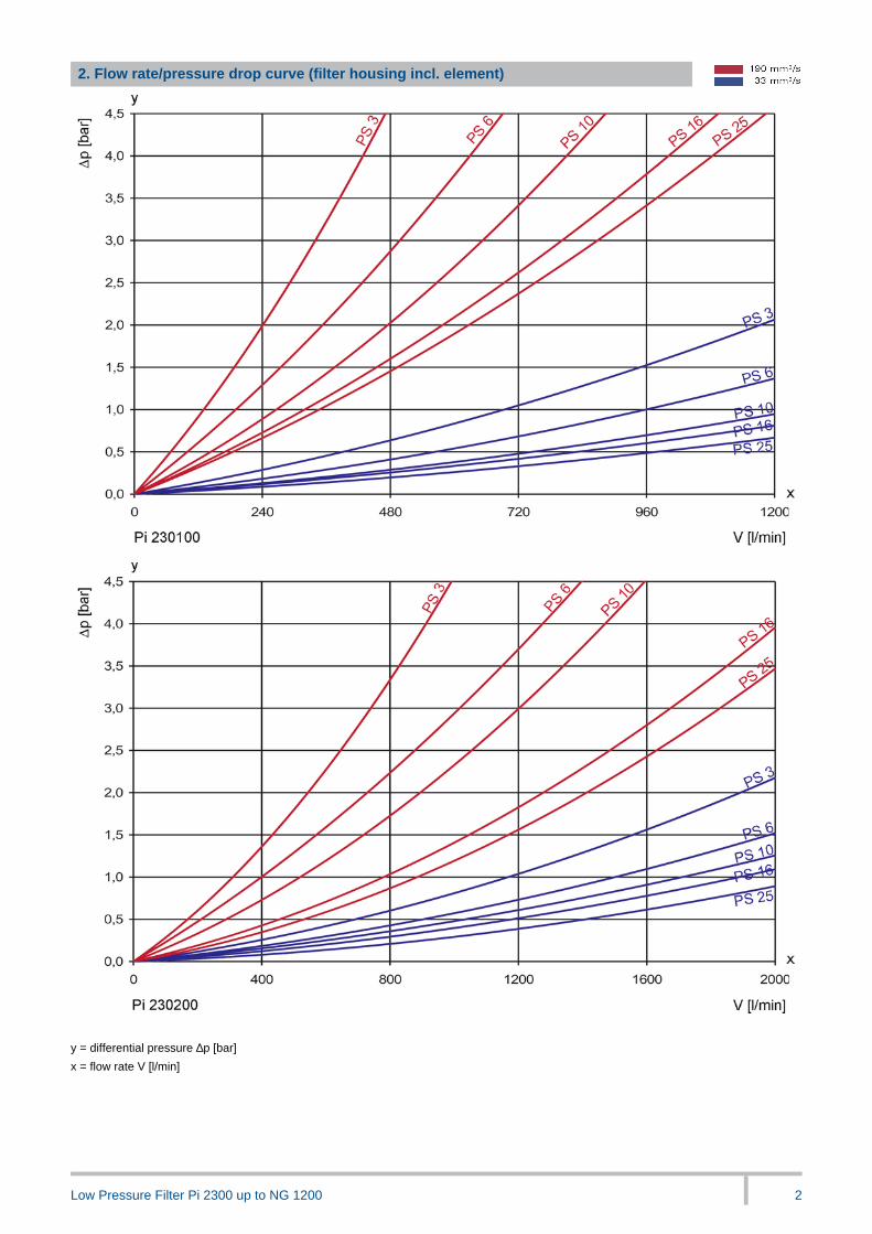
2. Flow rate/pressure drop curve (filter housing incl. element)
y = differential pressure ∆p [bar]
x = flow rate V [l/min]

Low Pressure Filter Pi 2300 up to NG 1200 3
3. Separation grade characteristics
y = beta-value
x = particle size [µm]
_
determined by multipass tests (ISO 16889)
calibration according to ISO 11171 (NIST)
4. Filter performance data
tested according to ISO 16889 (multipass test)
PS elements with
max. ∆ p 10 bar
PS 3 β5(C) ≥ 200
PS 6 β7(C) ≥ 200
PS 10 β10(C) ≥ 200
PS 16 β15(C) ≥ 200
PS 25 β20(C) ≥ 200
values guaranteed up to
10 bar differential pressure
5. Quality assurance
MAHLE filters and filter elements are produced according to the following international standards:
Norm Designation
DIN ISO 2941 Hydraulic fluid power filter elements; verification of collapse/burst resistance
DIN ISO 2942 Hydraulic fluid power filter elements; verification of fabrication integrity
DIN ISO 2943 Hydraulic fluid power filter elements; verification of material compatibility with fluids
DIN ISO 3723 Hydraulic fluid power filter elements; method for end load test
DIN ISO 3724 Hydraulic fluid power filter elements; verification of flow fatigue characteristics
ISO 3968 Hydraulic fluid power filters; evaluation of pressure drop versus flow characteristics
ISO 10771.1 Fatigue pressure testing of metal containing envelopes in hydraulic fluid applications
ISO 16889 Hydraulic fluid power filters; multipass method for evaluation filtration performance of a filter element
-
6. Symbols
Low Pressure Filter Pi 2300 up to NG 1200 4
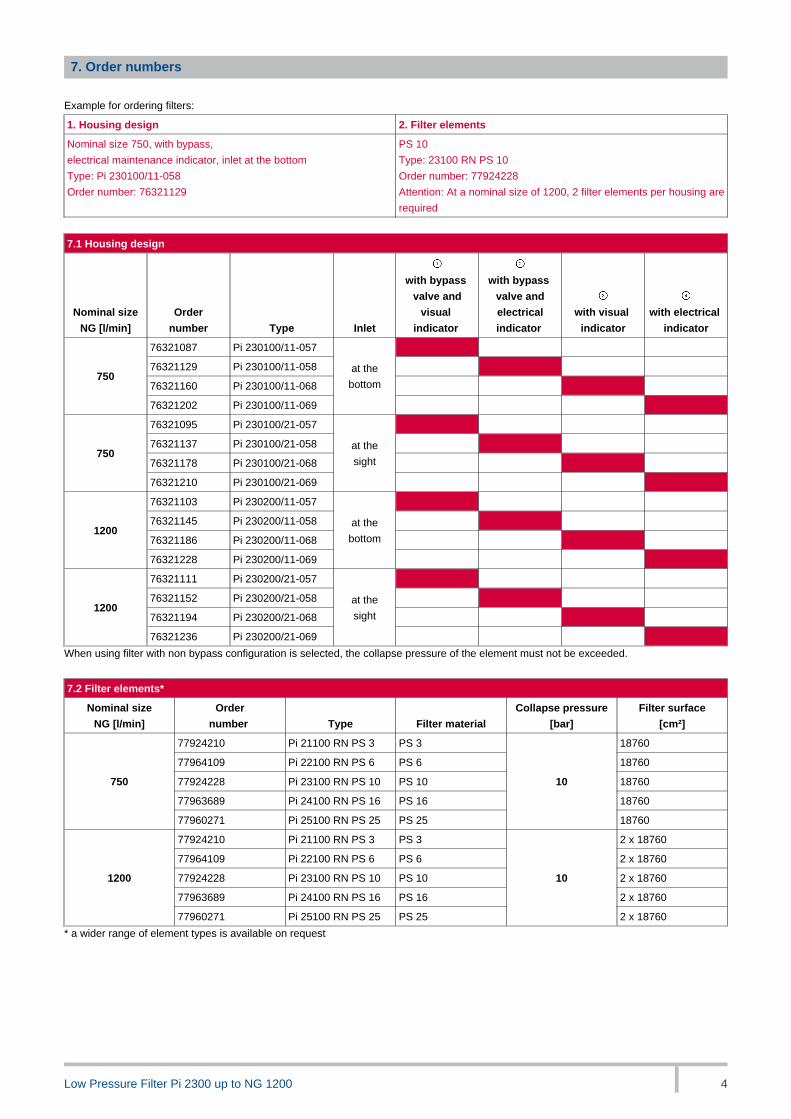
7. Order numbers
Example for ordering filters:
1. Housing design 2. Filter elements
Nominal size 750, with bypass,
electrical maintenance indicator, inlet at the bottom
Type: Pi 230100/11-058
Order number: 76321129
PS 10
Type: 23100 RN PS 10
Order number: 77924228
Attention: At a nominal size of 1200, 2 filter elements per housing are
required
7.1 Housing design
Nominal size
NG [l/min]
Order
number Type Inlet
with bypass
valve and
visual
indicator
with bypass
valve and
electrical
indicator
with visual
indicator
with electrical
indicator
76321087 Pi 230100/11-057
76321129 Pi 230100/11-058
76321160 Pi 230100/11-068750
76321202 Pi 230100/11-069
at the
bottom
76321095 Pi 230100/21-057
76321137 Pi 230100/21-058
76321178 Pi 230100/21-068750
76321210 Pi 230100/21-069
at the
sight
76321103 Pi 230200/11-057
76321145 Pi 230200/11-058
76321186 Pi 230200/11-0681200
76321228 Pi 230200/11-069
at the
bottom
76321111 Pi 230200/21-057
76321152 Pi 230200/21-058
76321194 Pi 230200/21-0681200
76321236 Pi 230200/21-069
at the
sight
When using filter with non bypass configuration is selected, the collapse pressure of the element must not be exceeded.
_
7.2 Filter elements*
Nominal size
NG [l/min]
Order
number Type Filter material
Collapse pressure
[bar]
Filter surface
[cm²]
77924210 Pi 21100 RN PS 3 PS 3 18760
77964109 Pi 22100 RN PS 6 PS 6 18760
77924228 Pi 23100 RN PS 10 PS 10 18760
77963689 Pi 24100 RN PS 16 PS 16 18760
750
77960271 Pi 25100 RN PS 25 PS 25
10
18760
77924210 Pi 21100 RN PS 3 PS 3 2 x 18760
77964109 Pi 22100 RN PS 6 PS 6 2 x 18760
77924228 Pi 23100 RN PS 10 PS 10 2 x 18760
77963689 Pi 24100 RN PS 16 PS 16 2 x 18760
1200
77960271 Pi 25100 RN PS 25 PS 25
10
2 x 18760
* a wider range of element types is available on request
Low Pressure Filter Pi 2300 up to NG 1200 5
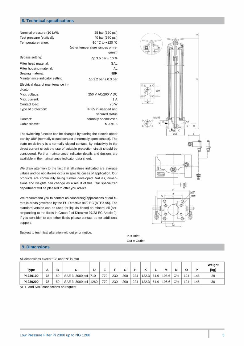
8. Technical specifications
Nominal pressure (10 LW): 25 bar (360 psi)
Test pressure (statical): 40 bar (570 psi)
Temperature range: -10 °C to +120 °C
(other temperature ranges on re-
quest)
Bypass setting: ∆p 3.5 bar ± 10 %
Filter head material: GAL
Filter housing material: AL
Sealing material: NBR
Maintenance indicator setting ∆p 2.2 bar ± 0.3 bar
Electrical data of maintenance in-
dicator:
Max. voltage: 250 V AC/200 V DC
Max. current: 1 A
Contact load: 70 W
Type of protection: IP 65 in inserted and
secured status
Contact: normally open/closed
Cable sleave: M20x1.5
-
The switching function can be changed by turning the electric upper
part by 180° (normally closed contact or normally open contact). The
state on delivery is a normally closed contact. By inductivity in the
direct current circuit the use of suitable protection circuit should be
considered. Further maintenance indicator details and designs are
available in the maintenance indicator data sheet.
-
We draw attention to the fact that all values indicated are average
values and do not always occur in specific cases of application. Our
products are continually being further developed. Values, dimen-
sions and weights can change as a result of this. Our specialized
department will be pleased to offer you advice.
-
We recommend you to contact us concerning applications of our fil-
ters in areas governed by the EU Directive 94/9 EC (ATEX 95). The
standard version can be used for liquids based on mineral oil (cor-
responding to the fluids in Group 2 of Directive 97/23 EC Article 9).
If you consider to use other fluids please contact us for additional
support.
_
Subject to technical alteration without prior notice.
_ In = Inlet
Out = Outlet
9. Dimensions
All dimensions except "C" und "N" in mm
Type A B C D E F G H K L M N O P
Weight
[kg]
Pi 230100 78 80 SAE 3, 3000 psi 710 770 230 200 224 122.3 61.9 106.6 G½ 124 146 29
Pi 230200 78 80 SAE 3, 3000 psi 1260 770 230 200 224 122.3 61.9 106.6 G½ 124 146 30
NPT- and SAE-connections on request
Low Pressure Filter Pi 2300 up to NG 1200 6
10. Installation, operating and maintenance instructions
10.1 Filter installation
When installing filter make sure that sufficient space is available to
remove filter element and filter housing. Preferably the filter should
be installed with the filter housing pointing upwards. The
maintenance indicator must be visible.
_
10.2 Connecting the electrical maintenance indicator
The electrical indicator is connected via a 2-pole appliance plug
according to DIN EN 175301-803 with poles marked 1 and 2. The
electrical section can be inverted to change from normally open to
normally closed position or vice versa.
-
10.3 When should the filter element be replaced?
1 . Filters equipped with visual and electrical maintenance
indicator:
During cold starts, the indicator may give a warning signal.
Press the red button of the visual indicator once again only after
operating temperature has been reached. If the red button
immediately pops up again and/or the electrical signal has not
switched off after reaching operating temperature. The filter
element must be replaced after the end of the shift.
2 . Filters without maintenance indicator:
The filter element should be replaced after trial run or flushing of
the system. Afterwards follow instructions of the manufacturer.
3 . Please always ensure that you have original MAHLE spare
elements in stock: Disposable elements (PS) cannot be
cleaned.
-
10.4 Element replacement
1 . Stop system and relieve filter from pressure.
2 . Loosen toggle, remove cover, and open drain valve. Housing
completely vented.
3 . Remove filter element from the filter bowl. With filter type
Pi 230200 remove the spacer sleeve from the elements clean
and reuse.
4 . Check seals for damages. Replace, if necessary.
5 . Make sure that the part number on the spare element
corresponds with the part number on the filter name-plate. With
the filter type Pi 230200 always change both elements. Remove
the plastic bag and push element over spigot in the filter head.
With filter type Pi 230200 put the sleeve on the element. On this,
telescope the second element and locate it.
6 . Close drain valve. Put the thumb screw together with the cover
on the centre rod and tighten strong. Filter must be bleeded!
LEER
LEER
LEER
LEER
LEER
LEER
LEER
LEER
MAHLE Industriefiltration GmbH
Schleifbachweg 45
D-74613 Öhringen
Phone +49 7941 67-0
Fax +49 7941 67-23429
www.mahle.com
76349514.04/2015
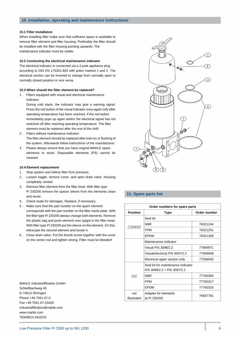
11. Spare parts list
Order numbers for spare parts
Position Type Order number
Seal kit
NBR 76321244
FPM 76321251
EPDM 76321269
Maintenance indicator
Visual PiS 3098/2.2 77669971
Visual/electrical PiS 3097/2.2 77669948
Electrical upper section only 77536550
Seal kit for maintenance indicator
PiS 3098/2.2 + PiS 3097/2.2
NBR 77760300
FPM 77760317
EPDM 77760325
not
illustrated
Adapter for elements
at Pi 23020076937791