low velocities in force mains: impacts and solutions · low velocities in force mains: impacts and...
TRANSCRIPT

We
fte
c 2
01
1
We
fte
c 2
01
1
Low Velocities in Force Mains:
Impacts and Solutions
Sean O’Rourke, P.E.
Bo Copeland, P.E.

We
fte
c 2
01
1
Low Velocities in Force Mains (FMs):
Presentation Outline
Overview
Complications and consequences
Contributing factors
Standards and engineering practice
Design and O&M solutions
Case studies
Conclusion
Questions

We
fte
c 2
01
1
Overview: Low Velocity in Force Mains
Primary Concerns:
1. Solids deposition
2. Gas pocket accumulation (incl. air binding)
3. Grease / Biofilm accumulation
Which can lead to:
Pipe deterioration
Reduced asset life
Increased life-cycle cost

We
fte
c 2
01
1
Overview:
Solid-liquid Horizontal Flow Behavior
Behavior is dependent on fluid properties,
velocity, particle sizes, density, etc.
Homogeneous suspension: Particles are uniformly
suspended and move at the same velocity as the fluid.
Heterogeneous suspension: A concentration gradient exists
within the pipe as coarse particles move slower and begin to settle.

We
fte
c 2
01
1
Overview:
Solid-liquid Horizontal Flow Behavior
Heterogeneous flow can lead to solids
deposition (“saltation regime”)
Particles travel in discontinuous movements or
by sliding/rolling along the bottom, if at all.
Sliding bed Stationary bed

We
fte
c 2
01
1
Overview:
Solid-liquid Horizontal Flow Behavior
A sliding bed can cause
abrasion of the pipe
invert.
Stationary beds reduce
available pipe cross-
sectional area.
Goal: Operate at adequate velocity
to achieve heterogeneous
suspension without solids
deposition

We
fte
c 2
01
1
Overview:
Gas pocket accumulation (air binding)
Sewer gas can come out of solution within a FM
and accumulate causing:
1. Reduction in pipe cross-sectional area
(increases pumping head)
2. Pipe corrosion from
H2S attack

We
fte
c 2
01
1
Additional Complications from Low
Velocity in Force Mains
In addition to solids deposition and
accumulation of gas pockets, other
complications may include:
Grease / biofilm accumulation
Microbial activity, H2S, odorous and corrosive
conditions

We
fte
c 2
01
1
Common Consequences Associated
with Low Velocity in FMs
Potential consequences:
Increased system head losses due to reduced cross-
sectional area (smaller ID) and higher roughness factor
Increased operating pressure (pump seals, piping, valves,
and other appurtenances)
Reduced pumping capacity

We
fte
c 2
01
1
Common Consequences Associated
with Low Velocity in FMs
Potential consequences (cont.):
Increased odor and corrosion within the FM and
downstream sewers and MHs
Pipe abrasion (sliding bed or H2S attack)
Increased O&M costs (e.g. electrical use, chemical use,
cleaning costs, etc.)
Reduced asset life

We
fte
c 2
01
1
Additional Considerations (designers)
Hazen-William’s equation is only valid in “transition zone”—
not at velocity or diameter extremes
(Moody chart)

We
fte
c 2
01
1
Contributing Factors
Circumstances that may lead to low velocity:
Small PSs with 4” FMs (80 gpm = ~2 fps)
Existing FMs reused for smaller PSs
Manifolded FMs serving multiple pump stations)
Systems with no / low initial contributing flow (incl.
phased developments)
High wet-weather / average flow ratio
High TDH (long FM or static head)

We
fte
c 2
01
1
Contributing Factors
Circumstances that may lead to low velocity:
PS down-sizing or other system changes
Wear of pump components (impellers, volutes, etc.)
Accumulation of gas pockets (air binding) in FM
Increased system headlosses:
o Grease accumulation
o Biofilm growth resulting from use of ammonium calcium
nitrate or certain other chemicals for odor and corrosion
control in a long FM
o FM relocations (e.g. add length and fittings)

We
fte
c 2
01
1
Standards and Engineering Practice for
Force Main Velocity
What Velocity is not “Low Velocity”?

We
fte
c 2
01
1
Standards and Engineering Practice for
Force Main Velocity
Ten States Standards (2004 ed.)1:
“At design pumping rates, a cleansing velocity of at least
2.0 ft/s should be maintained.”
Pumping Station Design, (3rd ed.)3:
“The lowest design velocity … for raw wastewater is 2 ft/s
to keep grit moving, and a peak daily velocity of 3.5 ft/s
is desirable to resuspend settled solids.”
“Velocities as low as 1.6 ft/s are tolerable with two daily
flushes.”
“If velocities are <2.5 ft/s, a daily flush at 4.0 ft/s long
enough to sweep out the entire volume … is desirable.”

We
fte
c 2
01
1
Standards and Engineering Practice for
Force Main Velocity
Piping Handbook (7th ed.)2:
“It is common practice to design sanitary sewers … to
provide for velocities of 2 ft/s .... Storm sewers are
commonly designed for a minimum full-flow velocity of
3 ft/s in order to resuspend sediment ….”
USEPA, “Wastewater Technology Fact Sheet:
Sewers, Force Main” (2000)4:
“Force mains … are typically designed for velocities
between 2 to 8 ft/s.”

We
fte
c 2
01
1
Standards and Engineering Practice for
Force Main Velocity
Sanitary and Industrial Wastewater
Collection—Pumping Stations and Force
Mains, Department of the Army and Air
Force (1985)5:
“Velocity criteria for force mains are based on the fact
that suspended organic solids do not settle out at a
velocity >=2.0 fps. Solids will settle at velocities <1.0
fps …. However, a velocity of 2.5 to 3.5 fps is generally
adequate to resuspend and flush the solids from the
line.”
“[For large pumping stations] it will generally be sufficient
to design for velocities of 0.5 up to 7.0 or 8.0 fps.”

We
fte
c 2
01
1
Standards and Engineering Practice for
Force Main Velocity
Although general consensus is >~2.0 ft/s to
prevent deposition and ~3.5 ft/s to
resuspend solids, application varies
between designers and projects
Adjustable-speed pumps
Multiple-pump systems
Shared / manifolded force mains
Frequency of cleansing / scouring

We
fte
c 2
01
1
Standards and Engineering Practice for
Force Main Velocity
Table B-9, Pumping Station Design, 3rd ed.3:
Velocities Required to Scour Air Pockets from Pipelines.

We
fte
c 2
01
1
Design Engineering Solutions:
Proper hydraulic evaluation, incl. maintaining
minimum velocity >=2 ft/s whenever possible
Evaluation of alternate alignments and profiles
Consideration of parallel pipes (if wide flow range)
Proper air valve selection—incl. avoiding air valves
wherever feasible by avoiding intermediate high
points and/or achieving air-scouring velocity
Proper odor / corrosion control measures
We
fte
c 2
01
1
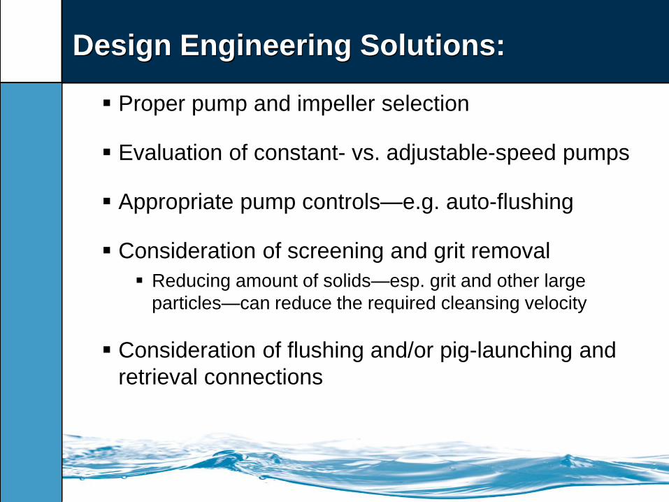
Design Engineering Solutions:
Proper pump and impeller selection
Evaluation of constant- vs. adjustable-speed pumps
Appropriate pump controls—e.g. auto-flushing
Consideration of screening and grit removal
Reducing amount of solids—esp. grit and other large
particles—can reduce the required cleansing velocity
Consideration of flushing and/or pig-launching and
retrieval connections

We
fte
c 2
01
1
Operation and Maintenance (O&M)
Solutions
Regular flushing at higher velocity (auto or manual)
Maintain pumps to preserve original pumping
capacity—debris-free, proper clearances, no blowby
Refurbish or replace impellers as needed to
maintain design (or higher) pumping capacity
Change pump controls

We
fte
c 2
01
1
Operation and Maintenance (O&M)
Solutions
Chemical “shocking” to kill biofilm growth
Mechanical Pipe Cleaning (e.g. pigging)
Odor / corrosion control chemical

We
fte
c 2
01
1
Operation and Maintenance (O&M)
Solutions
ICE PIGGING by Utility Service Group – Atlanta
(currently up to 24-inch diameter)
http://www.utilityservice.com/icepigging.html
We
fte
c 2
01
1
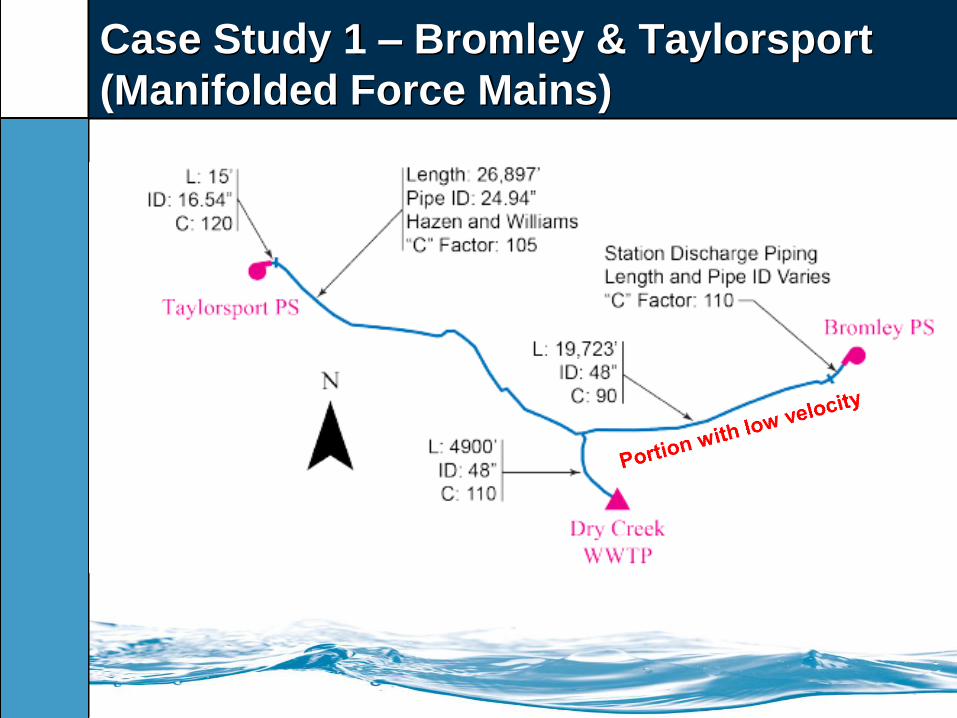
Case Study 1 – Bromley & Taylorsport
(Manifolded Force Mains)

We
fte
c 2
01
1
Case Study 1 – Bromley & Taylorsport
(Manifolded Force Mains)
Portion with low C-factor
We
fte
c 2
01
1
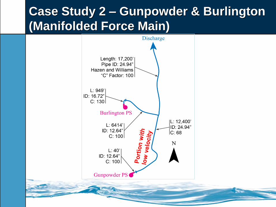
Case Study 2 – Gunpowder & Burlington
(Manifolded Force Main)

We
fte
c 2
01
1
Case Study 2 – Gunpowder & Burlington
Force Main
Original Flow Direction
New Flow Direction

We
fte
c 2
01
1
Case Study 2 – Gunpowder & Burlington
Force Main
Darker flow
due to flow
reversal in FM
resuspending
sedimentation

We
fte
c 2
01
1
Conclusion / Review
Remember:
Appropriate FM velocities (~2 – 8 ft/s)
Reasons why low velocities are undesirable
Potential complications and consequences
Contributing factors to low velocities
Design and O&M solutions
Proper understanding allows:
Engineers to make better design decisions
Utility operators to better understand FM O&M issues
Maximizing FM piping life and reducing life-cycle costs

We
fte
c 2
01
1
Questions?
(513) 469-2750

We
fte
c 2
01
1
References
1. The Great Lakes-Upper Mississippi River Board of State and Provincial Public
Health and Environmental Managers (2004) Recommended Standards for
Wastewater Facilities: Health Research Inc.: Albany, New York.
2. Nayyar, M. L. (2000) Piping Handbook, 7th ed.: McGraw-Hill: New York, New
York.
3. Jones, G. M. (2008) Pumping Station Design, 3rd ed.: Elsevier, Inc.: Burlington,
Massachusetts.
4. USEPA (2000) “Wastewater Technology Fact Sheet: Sewers, Force Main”: EPA
832-F-00-071.
5. Departments of the Army and the Air Force (1985) “Sanitary and Industrial
Wastewater Collection—Pumping Stations and Force Mains”: Army TM 5-814-2,
Air Force AFM 88-11, Vol. 2.
6. Poirier, M. R. (2000) “Minimum Velocity Required to Transport Solid Particles from
the 2H-Evaporator to the Tank Farm”: Westinghouse Savannah River Company:
Aiken, South Carolina: WSRC-TR-2000-00263.
7. United States Department of the Interior, Water and Power Resources Service
(1980) Air-Water Flow in Hydraulic Structures: Engineering Monograph No. 41.