low voltage circuit-breaker breaking · pdf filedesign office in the low-voltage power...
TRANSCRIPT

..........................................................................
Cahier technique no. 154
LV circuit-breakerbreaking techniques
R. Morel
Collection Technique

"Cahiers Techniques" is a collection of documents intended for engineersand technicians, people in the industry who are looking for more in-depthinformation in order to complement that given in product catalogues.
Furthermore, these "Cahiers Techniques" are often considered as helpful"tools" for training courses.They provide knowledge on new technical and technological developmentsin the electrotechnical field and electronics. They also provide betterunderstanding of various phenomena observed in electrical installations,systems and equipments.Each "Cahier Technique" provides an in-depth study of a precise subject inthe fields of electrical networks, protection devices, monitoring and controland industrial automation systems.
The latest publications can be downloaded from the Schneider Electricinternet web site.Code: http://www.schneider-electric.comSection: Experts' place
Please contact your Schneider Electric representative if you want either a"Cahier Technique" or the list of available titles.
The "Cahiers Techniques" collection is part of the Schneider Electric’s"Collection technique".
ForewordThe author disclaims all responsibility subsequent to incorrect use ofinformation or diagrams reproduced in this document, and cannot be heldresponsible for any errors or oversights, or for the consequences of usinginformation and diagrams contained in this document.
Reproduction of all or part of a "Cahier Technique" is authorised with theprior consent of the Scientific and Technical Division. The statement"Extracted from Schneider Electric "Cahier Technique" no. ....." (pleasespecify) is compulsory.
Robert Morel
«.... to my work friends and colleagues.»
Graduated with an engineering degree from ENSMM in Besançon andjoined Merlin Gerin in 1971.
Specialised in designing low-voltage switchgear and participated indesigning the Sellim system.
In 1980, took over development of Compact Circuit-breakers andInterpact switches.
In 1985, became manager of the Low-Voltage Current Interruptiondesign office in the Low-Voltage Power Components division.
no. 154LV circuit-breakerbreaking techniques
ECT 154 updated June 2000

Cahier Technique Schneider Electric no. 154 / p.2
Lexicon
α: closing voltage angle.
category (of a circuit-breaker): defined bystandard IEC 947.2.A = circuit-breaker not delayed on opening inshort-circuit conditions;B = circuit-breaker delayed on opening in short-circuit < Icw conditions.
E: DC rated voltage, AC peak voltage.
ϕ: voltage/current phase angle.
i, (i 0): current at an instant t, (at an instant t0).
ia: arcing current at an instant t.
îc: broken peak current.
Icc : short-circuit current.
Ics : rated service breaking capacity (expressedin kA or in % of Icu).
Icu : rated short-circuit ultimate breakingcapacity.
Icw : rated acceptable short current.
In: rated current in steady state, Ar.m.s.
Ip: prospective current.
Is: overload current.
r: generator impedance.
R, L, C: total components of broken circuit.
rating (of a circuit-breaker): rated current valueof the circuit-breaker, defined by the maximumsetting of the trip unit (electronic or thermaloverload protection).
size (of a circuit-breaker): the highest ratingaccepted by a circuit-breaker case. It is therated current of the device.
t, (t 0 ): time (initial instant).
ta: arcing time.
τ: time constant (τ = L / R).
u: voltage at an instant t.
ua: arcing voltage at an instant t.
Ua: stabilised arcing voltage.
UAC: Anode-Cathode voltage of eachelementary arc.
Ud+, Ud- : regeneration characteristics.
Un: rated voltage in AC, V r.m.s.
Ur: recovery voltage.
Wa: arcing energy.
WL0: initial inductive energy for i = i0.
ω: AC pulsation(ω = 2πf = 2π/T).

Cahier Technique Schneider Electric no. 154 / p.3
LV circuit-breaker breaking techniques
Contents
1 Introduction 1.1 Definition of currents to break p. 4
2 The electric arc 2.1 Its formation conditions p. 6
2.2 Its physical properties p. 6
2.3 Its electrical properties p. 6
2.4 Its extinguishing conditions p. 7
3 Using the arc to break the current p. 9
4 Breaking steady-state currents 4.1 In DC supply p. 10
4.2 In AC single-phase supply p. 11
4.3 In AC three-phase supply p. 12
5 Breaking prospective currents 5.1 Definitions p. 13
5.2 Breaking with limitation p. 16
5.3 Under DC voltage p. 16
5.4 Under single-phase AC voltage p. 16
5.5 Under three-phase AC voltage p. 17
5.6 The breaking parameters p. 17
5.7 Fuse breaking technique p. 18
6 The low voltage circuit-breaker 6.1 Its functions p. 19
6.2 Its technologies p. 20
6.3 Its performances p. 24
7 Conclusion p. 27
Bibliography p. 27
This Cahier Technique aims to:c define the currents to break in LV installations;c explain a phenomenon which occurs whenever a circuit is opened: theelectric arc ;c theoretically analyse the breaking of various currents by the arc placed inthe extinguishing condition;c describe breaking devices and in particular circuit-breakers from atechnological standpoint.
(with limitation)

Cahier Technique Schneider Electric no. 154 / p.4
1 Introduction
The energy sources for electrical installations areAC generators and transformers. All thesegenerators, however perfect, have an internalimpedance which has two major effects (seefig. 1 ).
c in normal operating conditions, this impedancecauses voltage to drop from no-load condition tobring it to Un when the generator delivers In;c when a short-circuit occurs, this impedancelimits the current to a value, given in multiples ofIn.
To take the example of transformers, their short-circuit voltage Ucc (as a %) corresponds to the
upper limit of their relative voltage drop underrated current, In.
For example, an Icc of In/5 % = 20 In is obtainedfor a short-circuit voltage of 5%, i.e. a current of29 kA for a 1000 kVA/400 V transformer. It is nothard to imagine the damage such a current couldcause in an installation (temperature rises andelectrodynamic forces are proportional to thecurrent square!).
Thus, even if all precautions are taken to makesuch an occurrence unlikely, protective devicesare still needed to break the short-circuitcurrents.
1.1 Definition of currents to break
Knowing the value of the current to break isnot enough to design a suitable breakingdevice !Current breaking is dependent on a number ofparameters relating to generators (a.c.generators or transformers), lines and loads:
c an electric circuit is always inductive, and thusthe very fluctuations in the current to break,
Fig. 1 : incidence of internal impedance Zi of energy sources on voltage delivered and their maximum short-circuitcurrents.
generate, as soon as the circuit is opened,negative current feedback which help maintainthe current. The value of this back-electromotivevoltage of the L di/dt type may be high whateverthe value of current i until this current iscancelled;
c the resistive value of the circuit to break is ofassistance in breaking as long as the current is
Un
U0
U = U - Zi In
In Icc
short-circuit currentoverloadcurrent
operationalcurrent
Un = Zi In∆
I
0

Cahier Technique Schneider Electric no. 154 / p.5
high, but ceases to be of any help when currenttends to zero, since the ohmic drop is thennegligible;c the capacities between live conductors,whether distributed ("stray" capacities ofgenerators and cables) or additional (capacitorbank in reactive energy compensation or filter),alter breaking conditions;c the frequency of the current to break, since intheory it is easier to break a.c. currents withperiodic zeros than d.c. currents;c finally, the voltage delivered by the generator.Once the current has been cancelled, thebreaking device must dielectrically withstand themains voltage still present.
In practice, there are three types of currentsto break:
1. Short-circuit currentIn a given point of an installation, this current isnot systematically equal to "20 In" of thegenerator:
c it depends on the generator characteristics, 3%< Ucc < 7% for example;c it may be smaller:v according to the fullness of the faultv according to the length and cross-section ofthe upstream lines;c it may be greater if a number of generators areparallel-connected.
2. Overload currentThe current may overshoot rated value andbecome inacceptable after a certain time:c during the transient period of load startup oroperation;c if the sum of the powers of the loads inoperation exceeds the designer's estimates forall or part of the installation.
3. Rated current (or lower)Since a circuit-breaker's function is to breakhigh short-circuit currents and overloads,it can also provide circuit and load control.

Cahier Technique Schneider Electric no. 154 / p.6
Fig. 2 : electric arc and influence of field E/d value.
2 The electric arc
The electric arc is no invention, but appeared tothe first physicist who tried to break a circuitthrough which a current flowed.Circuits, always inductive, supply electrons withsufficient energy to cross the distance in theconductor separation zone.The gas present, normally air, is ionised bythese "pioneer" electrons and the resultingplasma will then facilitate current flow.
2.1 Its formation conditions
The arc appears in gaseous atmospheres:c by dielectric breakdown between twoelectrodes:v beyond an electric field value E/d, dependenton electrode shape and on gas type and density(d = distance between electrodes ( see fig. 2 ) ;v further to moving over insulating materials inthe ambient gas.
c as soon as an electric circuit opens throughwhich current flows, even if the circuit is purelyresistive, a certain opening distance is necessaryto prevent dielectric breakdown.
Breaking thus seems somewhat compromised....unless a better understanding of thisphenomenon were to reveal remarkable andeven irreplaceable properties.Luckily this is the case !
Moreover, any attempt to reduce current rapidlycreates a high L di/dt thus favouring breakdownat any current level.
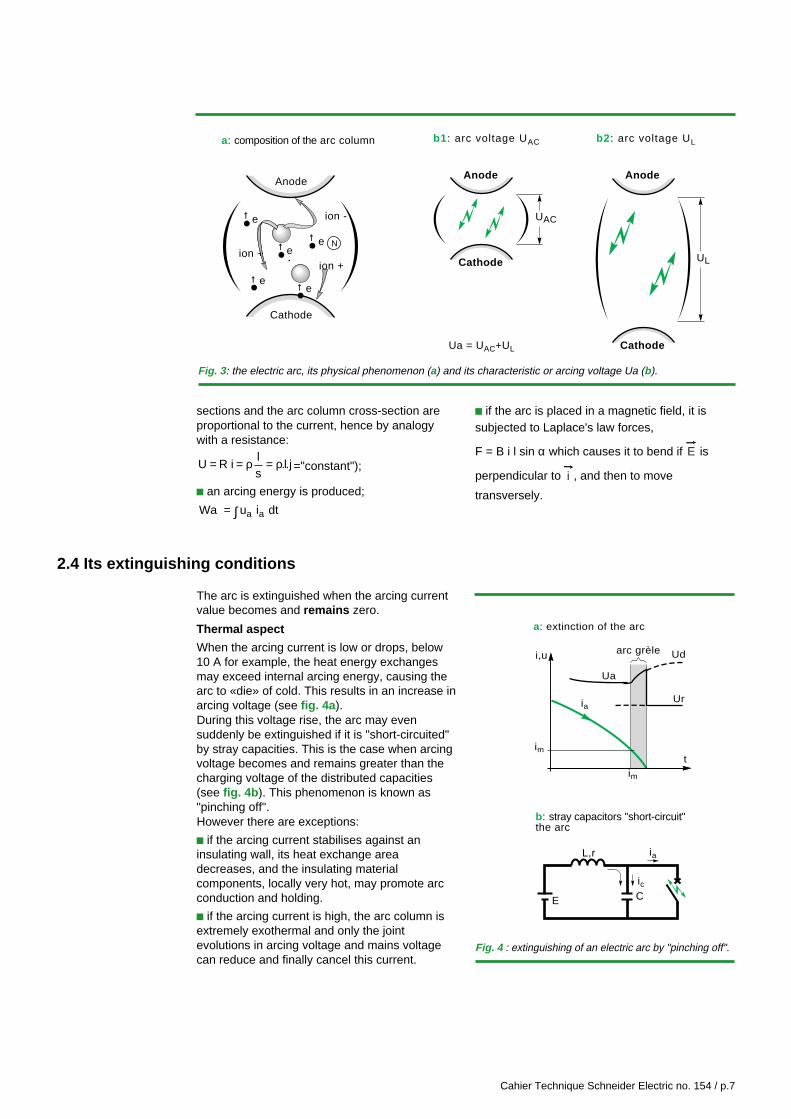
2.2 Its physical properties (see fig. 3a )
As soon as two contacts separate, one of them(cathode) transmits electrons and the other one(anode) receives them. Since electronicemission is by its very nature energy generating,the cathode will be hot. With the arc foot thusbecoming thermoemissive, the electrons aremostly emitted at the hot spot, resulting in arcstagnation which can give rise to metallicvapours. These vapours and the ambient gaswill then be ionised, hence:
c more free electrons ;
c the creation of positive ions which drop backon the cathode, thus maintaining its hightemperature;
c the creation of negative ions which bombardthe anode causing temperature to rise.All this occurs in a high temperature plasmacolumn, from 4 000 to 20 000 K according tocolumn current and confinement.
2.3 Its electrical properties (see fig. 3b )
c its most striking property is the appearance ofan arcing voltage, which has:v a fixed part, UAC ≈ 20 to 40 V which appearson the slightest separation of the contacts(depending on the materials used),v a variable part, UL = 50 to 100 V/cm, when thearc is stabilized in elongation in pressure-temperature balanced conditions.
i.e. a total value Ua = UAC + UL.
Note that:- the sign of Ua changes at the same time as thearcing current sign,- the arcing current value does not have any realeffect on arcing voltage. This is because the arc"works" with a virtually constant current density(j=i/s), (the anode and cathode spot cross-
E d
Cahier Technique Schneider Electric no. 154 / p.7
The arc is extinguished when the arcing currentvalue becomes and remains zero.
Thermal aspect
When the arcing current is low or drops, below10 A for example, the heat energy exchangesmay exceed internal arcing energy, causing thearc to «die» of cold. This results in an increase inarcing voltage (see fig. 4a ).During this voltage rise, the arc may evensuddenly be extinguished if it is "short-circuited"by stray capacities. This is the case when arcingvoltage becomes and remains greater than thecharging voltage of the distributed capacities(see fig. 4b ). This phenomenon is known as"pinching off".However there are exceptions:
c if the arcing current stabilises against aninsulating wall, its heat exchange areadecreases, and the insulating materialcomponents, locally very hot, may promote arcconduction and holding.
c if the arcing current is high, the arc column isextremely exothermal and only the jointevolutions in arcing voltage and mains voltagecan reduce and finally cancel this current.
Fig. 4 : extinguishing of an electric arc by "pinching off".
sections and the arc column cross-section areproportional to the current, hence by analogywith a resistance:
U R l j= = i =ls
ρ ρ.. ="constant");
c an arcing energy is produced;
Wa = u i dta a∫
2.4 Its extinguishing conditions
c if the arc is placed in a magnetic field, it issubjected to Laplace's law forces,
F = B i l sin α which causes it to bend if E is
perpendicular to i , and then to move
transversely.
Fig. 3 : the electric arc, its physical phenomenon (a) and its characteristic or arcing voltage Ua (b).
Anode
Cathode
UL
Ua = UAC+UL
b1: arc voltage UAC b2: arc voltage UL
Anode
Cathode
UAC
Anode
Cathode
←
e
ion +
N
ion -
ion +
←
e
a: composition of the arc column
←
e
←
e
←
e
a: extinction of the arc
arc grèle
t
i,u
ia
Ua
im
im
Ud
Ur
E C
L,r
b: stray capacitors "short-circuit" the arc
ic
ia

Cahier Technique Schneider Electric no. 154 / p.8
time of current zero (see fig. 6b ). Final breakingwill occur when subsequent change in mainsvoltage ceases to cross the regenerationcharacteristics in either positive or negativevalues.v when the instantaneous mains voltage valuehas the opposite sign to arcing voltage but has anabsolute lower value (see fig. 6c ). The arc ispermanently extinguished if the TRV does notexceed the regeneration characteristic.Otherwise, when the TRV breaks theregeneration "curve", a postarcing current of theelectroluminescent type may appear. In thiscase:- if the postarcing current is still of the smalltype, extinguishing conditions are still present;- if the postarcing current exceeds a criticalvalue under an equally critical voltage, thearcing current will be recovered and another"zero" will be required to break.
Dielectric aspect
The arcing current is not extinguished merely byreaching zero. In addition, the atmosphereionised up to that point must be dielectricallyregenerated in order to "withstand" the mainsvoltage still present !These regeneration phenomena ofrecombination of + or - ions and electrons arefortunately very fast ! Thus, in practice, for thearcing current to remain zero, mains voltagemust be less than the regeneration characteristic(Ud). If arcing voltage becomes and remainsgreater than mains voltage (in absolute value forac voltage), regeneration will begin as thecurrent zero approaches. The number of plasmaelectric charges adjusts itself to the strictminimum and becomes zero at the same time asthe current.However the arc and the stray capacities havethe same voltage until the arcing current isextinguished. Once this happens, this voltagerejoins mains voltage through free oscillationbetween these distributed capacities and circuitconstants L and R (see fig. 5 ). This voltage"connection" is known as the Transient RecoveryVoltage (TRV).Low capacities mean these oscillations have avery high frequency and are extremely damped.
These conditions are present:
c in dc voltage: (see fig. 6a );The arcing voltage, Ua, is greater than mainsvoltage, Ur, when the current is cancelled, andthe regeneration characteristic, Ud, remainsgreater than Ur with TRV.
c in ac voltage:v when the instantaneous mains voltage valuestill has the same sign as arcing voltage at the
Fig. 5 : the transient recovery voltage, TRV.
Fig. 6 : arc in extinguishing condition.a- in d.c. voltageb- in a.c. voltage with Ur of same sign as Ua at the timeof zero current,c- in a.c. voltage with Ur of opposite sign to Ua.
Ur
Ud
C
t
i,u
iTRV
im
im
«TRV»
ia
L,r
Ua
E
Ua
Uai,u
i,u
i,u Ua
t
t
t
i
Ud
Ud
Ud +
Ud
Ur
Ur
b
a
c
Ur
i
i
+
-
-
Cahier Technique Schneider Electric no. 154 / p.9
3 Using the arc to break the current
The current established on closing can becalculated by the extended Ohm's law:e - R i - L di/dt = 0.
Following a transient closing state, the currentbecomes stable or in steady state I = e
R.
On the basis of such a law, the current can onlybe cancelled permanently if the voltage "e"becomes zero or if R becomes infinite.In preference to these two extremes which wouldpresent too many operational restrictions, an arcwas introduced in the circuit for use of its Uavoltage properties and extinguishing conditions.As soon as the circuit opens, the equationbecomes:
e - R i - L di/dt - ua = 0.The current will thus be forced to zero or willpass through zero, and the arc extinguishingconditions will break the current.The examination of the two different cases belowprovides a progressive approach to the breakingtheory:
c the Ua arcing voltage was introduced in thecircuit when the current was in steady state(see chapter 4);
c the Ua arcing voltage was introduced inthe circuit before the current reached thestabilized value of the prospective current (seechapter 5).
Cahier Technique Schneider Electric no. 154 / p.10
Steady-state currents are rated currents,overload currents and short-circuit currentswhich have reached a stable value on circuitopening.Circuit opening may be:c voluntary, controlled by the user, completelyseparate from current value;
4.1 In DC supply
c "reflex", by the action of a device affected bycurrent value and directly or indirectly controllingcircuit opening.For simplicity's sake, breaking conditions areexamined :c in d.c. voltage;c then in a.c. voltage.
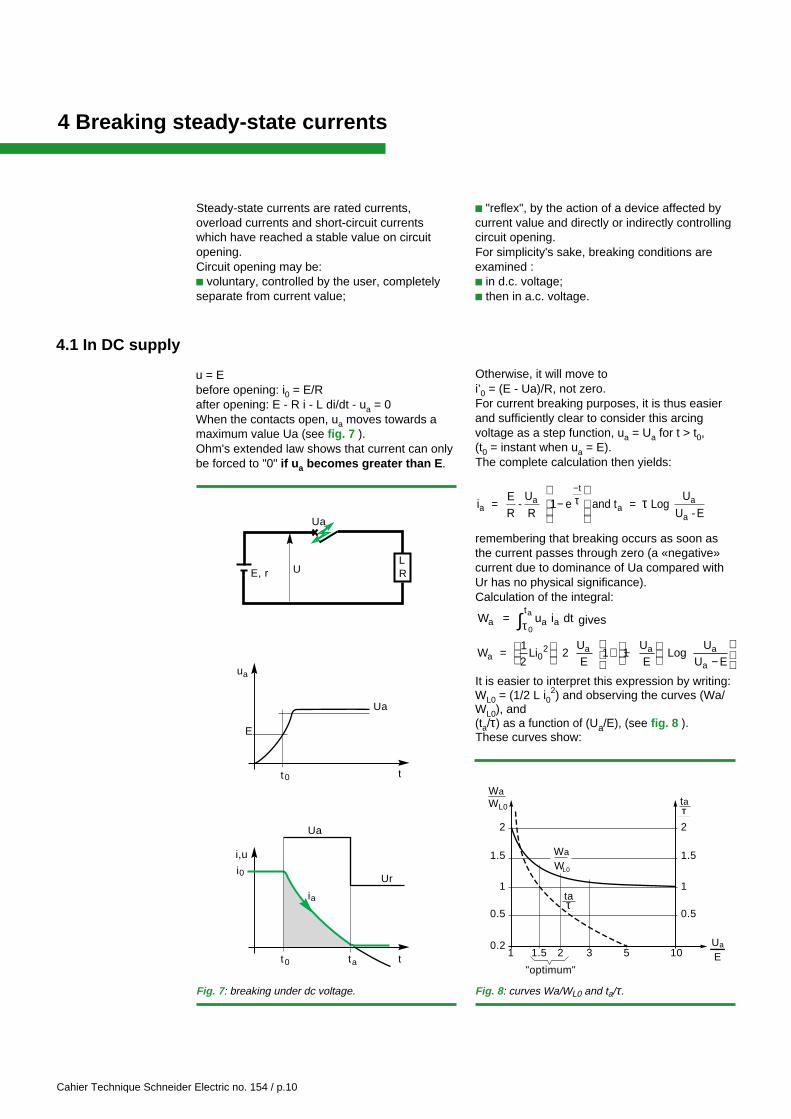
u = Ebefore opening: i0 = E/Rafter opening: E - R i - L di/dt - ua = 0When the contacts open, ua moves towards amaximum value Ua (see fig. 7 ).Ohm's extended law shows that current can onlybe forced to "0" if u a becomes greater than E .
Otherwise, it will move toi’0 = (E - Ua)/R, not zero.For current breaking purposes, it is thus easierand sufficiently clear to consider this arcingvoltage as a step function, ua = Ua for t > t0,(t0 = instant when ua = E).The complete calculation then yields:
i = ER
-UR
and t = Log U
U -Eaa
aa
a 1−
−
et
τ τ
remembering that breaking occurs as soon asthe current passes through zero (a «negative»current due to dominance of Ua compared withUr has no physical significance).Calculation of the integral:
W u i dta a a = ∫τ0
ta gives
WUE
UE
LogU
U Eaa a a
a =
12
Li02 2 1 1
+ −
−
It is easier to interpret this expression by writing:WL0 = (1/2 L i0
2) and observing the curves (Wa/WL0), and(ta/τ) as a function of (Ua/E), (see fig. 8 ).These curves show:
Fig. 8 : curves Wa/WL0 and ta/τ.Fig. 7 : breaking under dc voltage.
4 Breaking steady-state currents
2
1
0.5
0.21 2 5 101.5 3
1.5
2
1
0.5
1.5
"optimum"
W
ta__τ
ta__τ
L0
Ua
E
WL0
Wa
Wa
E, rLRU
Ua
Ua
Ur
t
i,u
t
ia
t 0 ta
t 0
Ua
u
i0
E
a

Cahier Technique Schneider Electric no. 154 / p.11
c if Ua = E then Wa/WL0 = 2 only! But breakingtime is infinite!
c if Ua is very big or even infinite then:Wa/WL0 = 1.Arcing energy is equal to initial inductive energyand breaking time is virtually zero: arcing powerWa/ta is very high!c that the "bend" of curve Wa/WL0 is a practicaloptimum and thus that the value :
4.2 In AC single-phase supply
1 5 2 5, ,< <UEa
is a good compromise; then
Wa ≈ 1.2 WL0 and ta ≈ τ.
The coefficient 1.2 (read on the bend) is verysatisfactory due to its proximity to the "1"minimorum minimum, difficult to reach.
u = E sin ωti = I0 cos (ωt + ϕ), with
cos L
L + R2ϕ ω
ω =
( )2
and Ι02 2
=( ) +
E
L Rω
The arc appears as soon as the contactsseparate, and evolution of its voltage in time mayappear complex. However ua still has the sign of"i" and its mean absolute value tends towards Ua(see fig. 9 ).The mathematical study of ia, ta and Wa, basedon extended Ohm's lawu - R i - L di/dt - ua = 0 is still possible but not soeasy.Moreover, since these calculations do notconsider the voltage recovery conditions of reala.c. breaking, the two cases Ua ≥ E and Ua << Emust be analysed:
c if Ua ≥ E, (see fig. 10 ), the arcing voltagehelps to force the current to "0" and to hold it
there, whatever the phase shift "ϕ" of "i"compared with "u";
c if Ua << E, breaking is still possible andeasier, overall, than in d.c. because of the"natural" zeros of i.
Successful breaking depends on postarcingphenomena at each zero current. In fact, thiscondition can be summed up by a race betweenarc dielectric regeneration and mains voltage.
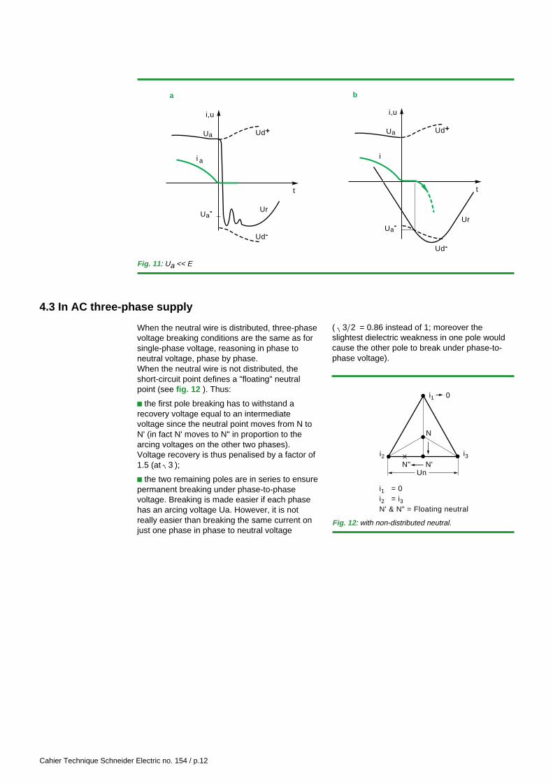
Let us look at two possibilities:v if the symmetry of Ua acquired at a currentzero is greater than mains voltage at that instant(see fig. 11a ), including TRV, then the dielectricregeneration evolution "curve" remains greaterthan mains voltage and breaking occurs;
v if the symmetry of Ua acquired at a currentzero is less than mains voltage at that instant(see fig. 11b ), including TRV, then the mainsvoltage may well break the dielectricregeneration curve if this curve is too slow.In this case, arcing may reoccur and no breakoccurs, at least not at that current zero!In both these cases, the power factor cos ϕ ofthe circuit to break has considerable influencedue to the phase shift of the current zeroscompared with mains voltage value.In particular, if cos ϕ ≈ 1, voltage and currentvalues are zero at the same time and breakingis easy.
Fig. 9 : breaking under a.c. voltage. Fig 10 : Ua ≥ E
i ,ua a
IUaI
t
t
Ua
Uaia
t
i,uUa
Ua
UrUa(t)i
t 0 ta
-
+
Cahier Technique Schneider Electric no. 154 / p.12
4.3 In AC three-phase supply
When the neutral wire is distributed, three-phasevoltage breaking conditions are the same as forsingle-phase voltage, reasoning in phase toneutral voltage, phase by phase.When the neutral wire is not distributed, theshort-circuit point defines a "floating" neutralpoint (see fig. 12 ). Thus:
c the first pole breaking has to withstand arecovery voltage equal to an intermediatevoltage since the neutral point moves from N toN' (in fact N' moves to N" in proportion to thearcing voltages on the other two phases).Voltage recovery is thus penalised by a factor of1.5 (at 3 );
c the two remaining poles are in series to ensurepermanent breaking under phase-to-phasevoltage. Breaking is made easier if each phasehas an arcing voltage Ua. However, it is notreally easier than breaking the same current onjust one phase in phase to neutral voltage
Fig. 11 : Ua << E
( 3 2 = 0.86 instead of 1; moreover theslightest dielectric weakness in one pole wouldcause the other pole to break under phase-to-phase voltage).
Fig. 12 : with non-distributed neutral.
i1 = 0i2 = i3N' & N" = Floating neutral
N'Un
i1 0
i3i2N"
N
i,u
Ua-
t
i
Ud+
Ud-
a
Ur
a
Ua
b
i,u
Ua-
t
i
Ud+
Ud-
Ur
Ua

Cahier Technique Schneider Electric no. 154 / p.13
5 Breaking prospective currents (with limitation)
5.1 Definitions
Right from the start the current has the samecurve as in steady state, and a peak value ofE/Z.v α = 0, known as the "asymmetrical condition"(see fig. 14c ).The current curve is given by:
i = ER
sin t - sin e ω ϕ ϕ( ) +
− RL
t
Thus the first peak value of the current is afunction of the circuit cos ϕ.c under three-phase a.c. voltage (see fig. 15 )The current in each phase may result in thesame special cases (symmetrical andasymmetrical) as in single-phase. In any case,whatever the value of α, there is nearly always:
c a phase in quasi-symmetrical condition,
c a phase in quasi-asymmetrical condition,
c the last phase is said to be in "small loop".
Prospective current
In an installation, this is the current which wouldflow through a circuit if each connection devicepole or the fuse were replaced by a conductor ofnegligible impedance (IEC 60050).In a switchgear test circuit, it is the calibrationcurrent.
Remember that:
c under d.c. voltage , current evolution takes theform:
i ER
= −
= −
1 1e et
p
tτ τI (see fig. 13 ) ;
c under single-phase a.c. voltage: the moment"of appearance of the fault" or the moment ofclosing, compared with mains voltage value,considerably influences evolution of the transientcurrent.If this moment were characterised by its closingvoltage angle α, voltage may be written as:
u = E sin (ωt + α), (cf. fig. 14a )
Current evolution takes the shape:
i = ER
sin t + - sin - ω α ϕ α ϕ( ) − ( )
−e
RL
t
with two components:v an a.c. one, with a phase shift of ϕ withrespect to voltage,v a d.c. one, tending to zero when t tends toinfinity.
Two special cases are defined by:
v α = ϕ, known as the "symmetrical condition"(see fig. 14b )The current shape is:
i =ER
sin tω
Fig. 13 Fig. 14: current evolution under a.c. voltage.
«α» t
u
a
α = ϕ
i
i "symmetrical"
b
t
c
α = 0
ii "asymmetrical"
t
ER
i
Ip
τ
ER
t

Cahier Technique Schneider Electric no. 154 / p.14
Fig. 15 : oscillograms for test circuit breaking under three-phase a.c. voltage, with α = 0 (for phase 1).
Channel 140 kAI1
Channel 4205 VV1
Channel 240 kAI2
Channel 5204 VV2
Channel 340 kAI3
Channel 6204 VV3
.005 200.0
VOLTA laboratory A3076 90/05/31/001
quasi-symmetry
small loop
10 ms
Voltage waves Current waves
real assymmetry

Cahier Technique Schneider Electric no. 154 / p.15
5.2 Breaking with limitation
The expression means that measures are takento prevent the short-circuit current from reachingthe maximum peak value of its prospectivecurrent (see fig. 16a ).This objective is an important one and in manycases vital if damage to the installation is to beavoided.Arc limitation is only possible if arcing voltagequickly becomes and remains greater thanmains voltage (cf. fig. 16b ).
In fact, Ohm's law, e-R i -Ldidt
-Ua = 0 , is used
to define the three limitation conditions(see fig. 16c ) :
c creation of an arcing voltage as early aspossible;
c increase of this arcing voltage as quickly as
possible to obtain Ua = e - R i and thus L didt
= 0 ,
which means that the current has then reached amaximum value îc;
c holding this arcing voltage, Ua, at as high avalue as possible; di/dt is then negative and thecurrent is forced to 0.
In short «Early, Quickly, High ». Such is theslogan for :
"Using the arc to break…prospective currents, …with limitation"
5.3 Under DC voltage
DC voltage takes the form u(t) = E
c Until the circuit is opened, current evolves asin the formula:
i ER
= −
= −
− − 1 1e p e
t tτ τI
c When the circuit is opened, an arcing voltageappears. If it increases rapidly, its overallevolution may be likened to a step function witha rising voltage defined by ua = E at an instant t0(see fig. 17 ).The current, having reached a value i0, thendecreases exponentially and disappears after atime ta << τ.
Calculation of arcing energy:
Wa u i dtat
ta
o
a ≈ ∫ ,
Wa L i 2 UR i i
iU - Un0
a
0 0
0
a≈
−−
+
12
1 12 U UnR
LogRa
Fig. 16 : limitation conditions.
Fig. 17 : limitation under d.c. voltage.
i
u
i
Ip
t
t
t
U
a
c
Ur
U
didt
= 0
didt
< 0
îc
b a
a
broken i
Ip
Ip
i0
ua
E
Ua
t0
ic
τ t
t

Cahier Technique Schneider Electric no. 154 / p.16
5.4 Under single-phase AC voltage
Hence the curve network (Wa/WL0),(see fig. 18 ), when the limitation ratiok = i0 / ip is introduced.
Note that the smaller the ratio k, the lowerthe arcing energy. This energy is «optimal»for 1.5 < Ua / E < 2.5, which was the casein steady-state current.
Fig. 18 : limitation curves.
In limitation conditions, this current is broken asthough it were temporarily a DC voltage break.
c In the symmetrical condition , in particular, itis virtually equivalent to consider breaking underprospective current with a mains voltageE = Un 2 (see fig. 19a ).
c In the asymmetrical condition , limitation isoften better since the arcing voltage «breaks»the mains voltage before the current really haschance to evolve (see fig. 19b ).
c In all the «intermediate » cases, with the«small loop», breaking with limitation may onlyoccur on the second current half-wave, since thestrength of the first half-wave was too low(see fig. 19c ).
Remark:Efficient limitation on high short-circuit currents isonly possible if the arcing voltage appears withina time much less than T/4.
Fig. 19 : limitation under single-phase a.c. voltage.
a
i,u
Un 2
Ua
Ur
t
ip "SYM."
T/2
ic
ip "small loop"
ip
i
ia
t
cb
t
ip "ASYM."
i,u
ic Ur
T/2
1
0
15
2
0,5
0,75
0,20,3
0,850,95
1,2
k = 0,25
k = 0,5
k = 0,6
k = 0,7
k = 0,8
k = 0,9
k = 1
UaE
WaWL0
1 1,5 2 2,5 3

Cahier Technique Schneider Electric no. 154 / p.17
5.5 In a three-phase AC system
Two cases should be considered:
1st case: separate opening of the polesEach phase generates an arcing voltageaccording to the current flowing through it(see fig. 20 ).
At first sight, it is as though:
c one of the phases breaks in the single-phasesymmetrical condition, but with voltage recoveryin intermediate voltage;
c finally, the other two phases ensure two-phasebreaking of a «current tail».
2nd case: simultaneous opening of the polesThe current of the phase in the symmetricalcondition is the first to react on a tripping deviceensuring very fast opening of all poles.
In this case, the arcing voltages develop on allthree phases at the same time. It is as thoughthe phase in the quasi-symmetrical conditionwere broken in its phase-to-phase voltage with adouble arcing voltage.
The opening of all poles must take place within atime < T/4 and will be most efficient for < T/8.The «small loop» phase will then be brokenalthough little current has flown through it.
This breaking behaviour:
c occurs on devices with low overall inertia oftheir moving parts;
c is sought on large-size equipment with ultra-fast external operating energy (for example, withThomson effect with capacitive discharge).
Fig. 20 : oscillograms for test circuit breaking in three-phase voltage with separate opening of poles.
5.6 The breaking parameters
c «thermal stress» or
Joule's integral = i dt2∫This term is the recognised expression.
Since the shape of the broken current does notcorrespond to a simple mathematical function,
channel 120 kA
channel 4200 V
channel 220 kA
channel 5200 V
channel 320 kA
channel 6200 V
VOLTA laboratory A0201 89/02/014
I1
V1
I2
V2
I3
V3
1 ms
pi
p1i
2
The parameters chosen to assess breakingefficiency are:
c broken peak current = îc(absolute value of the maximum peak current)Knowledge of this value enables definition of themaximum electrodynamic stresses in the circuit;

Cahier Technique Schneider Electric no. 154 / p.18
this integral is calculated step-by-step bycomputer.
This integral expresses both thermal andelectrodynamic energy stresses on the circuitelements;
c breaking time = taTotal breaking time if the circuit is three-phase;
c maximum arc voltage = UaMagnitude :v 250 to 500 V for standard circuit-breakers,v 600 to 900 V for limiting circuit-breakers.
These «overvoltages» do not presenta risk since they are lower than thetest voltages standardised for LVinstallations;
c arc energy = u i dta a∫This integral is also calculated step-by-stepby computer and expresses the energyconsumed in the arcing zone.Magnitude: 1, 10, 100 kJ according to thedevice and the currents broken.It conditions device breaking endurance.
5.7 Fuse breaking technique
Fig. 21 : the fuse, its composition and its characteristic breaking curves.
A fuse breaks because of the arc.Its relative simplicity lies in the fact that acarefully calculated filament is brought to itsmelting temperature by the current flowingthrough it.
For high currents, the temperature rise resultingin filament melting is of the adiabatic type; itspre-arcing energy is defined by the formula:
R itpa
20∫ dt = m c Tf
where R = filament resistance,m = filament mass,c = thermal capacity,Tf = melting temperature,tpa = prearcing time.
This «prearcing» thermal energy is separatefrom mains voltage.
The arc quickly assumes the length of the meltedfilament and the arcing voltage takes on a valuein accordance with this length and the pressure
appearing in the breaking unit(see fig. 21 ).This breaking unit can be filled with silica powderwhich, as it melts, will absorb the arcing energy.Note: the current "tail" is explained by the«preferential» path created by the arc in themelted silica. The arc decreases in size againstthe walls which are still warm.
A few remarks about fuses:
c their action is restricted to high overload andshort-circuit currents;
c some types of fuses have strikers for meltindication purposes, as well sometimes as toindirectly act on an extra breaking device toensure opening of all phases;
c following a fuse fault and melt, some«survivors» may have come close to melting andtheir characteristics may be altered. They maythen melt inopportunely under a current lowerthan their rating. All fuses must therefore bereplaced at the same time.
������������������������������
@@@@@@@@@@@@@@@@@@@@@@@@@@@@@@
������������������������������
ÀÀÀÀÀÀÀÀÀÀÀÀÀÀÀÀÀÀÀÀÀÀÀÀÀÀÀÀÀÀ
������������������������������
@@@@@@@@@@@@@@@@@@@@@@@@@@@@@@
������������������������������
ÀÀÀÀÀÀÀÀÀÀÀÀÀÀÀÀÀÀÀÀÀÀÀÀÀÀÀÀÀÀ
������������������������������
@@@@@@@@@@@@@@@@@@@@@@@@@@@@@@
������������������������������
ÀÀÀÀÀÀÀÀÀÀÀÀÀÀÀÀÀÀÀÀÀÀÀÀÀÀÀÀÀÀ
������������������������������
@@@@@@@@@@@@@@@@@@@@@@@@@@@@@@
������������������������������
ÀÀÀÀÀÀÀÀÀÀÀÀÀÀÀÀÀÀÀÀÀÀÀÀÀÀÀÀÀÀ
������������������������������
@@@@@@@@@@@@@@@@@@@@@@@@@@@@@@
������������������������������
ÀÀÀÀÀÀÀÀÀÀÀÀÀÀÀÀÀÀÀÀÀÀÀÀÀÀÀÀÀÀ
������������������������������
@@@@@@@@@@@@@@@@@@@@@@@@@@@@@@
������������������������������
ÀÀÀÀÀÀÀÀÀÀÀÀÀÀÀÀÀÀÀÀÀÀÀÀÀÀÀÀÀÀ
������������������������������
@@@@@@@@@@@@@@@@@@@@@@@@@@@@@@
������������������������������
ÀÀÀÀÀÀÀÀÀÀÀÀÀÀÀÀÀÀÀÀÀÀÀÀÀÀÀÀÀÀ
������������������������������
@@@@@@@@@@@@@@@@@@@@@@@@@@@@@@
������������������������������
ÀÀÀÀÀÀÀÀÀÀÀÀÀÀÀÀÀÀÀÀÀÀÀÀÀÀÀÀÀÀ
������������������������������
@@@@@@@@@@@@@@@@@@@@@@@@@@@@@@
������������������������������
ÀÀÀÀÀÀÀÀÀÀÀÀÀÀÀÀÀÀÀÀÀÀÀÀÀÀÀÀÀÀ
������������������������������
@@@@@@@@@@@@@@@@@@@@@@@@@@@@@@
������������������������������
ÀÀÀÀÀÀÀÀÀÀÀÀÀÀÀÀÀÀÀÀÀÀÀÀÀÀÀÀÀÀ
������������������������������
@@@@@@@@@@@@@@@@@@@@@@@@@@@@@@
������������������������������
ÀÀÀÀÀÀÀÀÀÀÀÀÀÀÀÀÀÀÀÀÀÀÀÀÀÀÀÀÀÀ
������������������������������
@@@@@@@@@@@@@@@@@@@@@@@@@@@@@@
������������������������������
ÀÀÀÀÀÀÀÀÀÀÀÀÀÀÀÀÀÀÀÀÀÀÀÀÀÀÀÀÀÀ
Fuse link
S i l i ca
Insulating enclosure
Connection device
i ip
tpaU
i
t
t
t
ia
Ur
Ua

Cahier Technique Schneider Electric no. 154 / p.19
6 The low voltage circuit-breaker
A circuit-breaker (see fig. 22 ) is a connectiondevice able to close and break a circuitirrespective of current up to its ultimatebreaking capacity: Icu (refer to standard IEC60947-2).
Although its main function is to break short-circuit and overload currents by self-energized«reflex» action, it also breaks «normal» currentsand overload currents by voluntary action fromexternal sources.
Moreover, after opening, it provides voltageinsulation of the broken circuit.
6.1 Its functions
The circuit-breaker's design enabling it tohouse all these functions in the same casehas led to the adoption of specific solutionsregarding:
c closing/opening mechanisms;
c trip units;
c pole circuits ;
c breaking elements (contacts, arc chutes...).
The purpose of this chapter is to analyse itsfunctions, technologies and performances.
Fig. 22 : cross-section of an industrial 400 A LV circuit-breaker.
Circuit closingBy action on the closing mechanism, currentflows to supply the load as soon as the slightestcontact is established. When energized, someloads absorb currents far greater than rated
current In (e.g. motor 7 to 8 In for a fewseconds). To prevent these overcurrentsresulting in dangerous phenomena for thecontact zone (erosion by arcs), closing must beprompt, especially for values ≥ 100A.

Cahier Technique Schneider Electric no. 154 / p.20
If they are to suit all standard cases, circuit-breakers must therefore be able to establishcurrents 15 to 20 times greater than their ratedcurrent.Specific measures must be taken to perform thisfunction, since a circuit-breaker must always beready to open again in the event of aninstallation fault, even during or just after it hasclosed !
Current conducting
This passive function requires a number ofconstruction precautions if both an acceptabletemperature rise and the possibility of quickopening are to be obtained.Furthermore, if the circuit-breaker is of thediscriminated type, it may require a highelectrodynamic withstand to accept short-circuitcurrents during the discrimination time,necessary for the downstream devices tooperate.
Circuit opening, current breaking
c by voluntary action on the mechanism, manualor remote controlled; any current can be broken.
6.2 Its technologies
c by reflex action on the mechanism by the tripunit due to an overcurrent. The circuit-breakerautomatically and permanently opens, even if theoperating device is held in the "closed" position.
c by action of an auxiliary trip unit on themechanism:Undervoltage, energising, earth leakage currentdevices... Opening is automatic and permanent:the current can have any value at this time.
Isolation
When the circuit-breaker is open, a certainisolation level is required between the"energized" and "de-energized" parts.The level is checked by insulation tests such asthose prescribed by IEC 60947-2 standards:
c a maximum leakage current test between inputand output under max Ue;
c an impulse voltage (e.g. 12.3 kV instead of the9.8 kV required for a device of the same typewithout this function);
c a mechanism sturdiness test, known as the"welded contact" (see the Schneider Electric"Cahier Technique" no. 150).
The mechanisms
The three basic principles are:
c mechanism «with 2 stable positions»(for circuit-breakers with ratings under 100 A);
c mechanism with «3 stable positions»particularly used in industrial circuit-breakers(see fig. 22). Their operating device enables:v sudden closing of contacts, regardless of howthey are operated,v sudden opening of contacts, regardless of howthey are operated,v opening by tripping, suddenly and even if thehandle is held. Resetting must then precedereclosing,v positive break (the operating device can onlybe padlocked in the "O" position if the contactsare really open);
c mechanism for high current, moresophisticated circuit-breaker. This type has adevice for charging energy storage beforeclosing and opening, thus allowing an "O - FO"cycle without intermediate resetting.
The trip units
In view of trip unit diversity, only the basicprinciples providing the minimum knowledgerequired to study overcurrent breaking, arereviewed below:
c The thermal-magnetic trip units:
v in overload conditions, significant overheatingof a particular current (or temperature in manycases) causes tripping by a "thermal-mechanical" element, generally a bimetal strip.- Trip unit nominal rating is defined bytemperature rise conditions in asymptoticheating.The trip unit can be "compensated" to prevent itbeing affected by ambient temperature.- in high overload conditions, temperature risesdevelop in adiabatic heating. Tripping time thusdepends on the circuit-breaker's preliminarytemperature rise.
v in short-circuit conditions, as from a certaincurrent threshold, tripping is performed"instantaneously" by a magnetic circuit whichactuates an armature or a core.This threshold is defined on a current impulse of200 ms. However its action time is extremelyreduced (3 to 5 ms) for high currents;
c "electronic" trip unitsTheir prime purpose is evaluation of the currentflowing through the circuit-breaker poles to takethe appropriate action on a tripping device.Their advantages are:
v greater precision of target thresholds,
v tripping curves which can be adjustedaccording to use,
v local or remote information possibilities.

Cahier Technique Schneider Electric no. 154 / p.21
The contactsLV circuit-breaker contacts are made up ofconductive element zones pressurised in thesame direction as their possible displacement(see fig. 23 ), consequently, no "knife" contactsas in many switches.
Two physical phenomena linked to the materialsused and to contact force should be noted:
c contact resistance (Rc)This must be as small as possible since itconditions the ohmic power developed at thecontact point which must be discharged byconduction. These temperature rises canaccentuate oxidation and corrosion phenomena;to guard against them, contacts may be made ofcopper up to 100 A and must be made of silverat higher values.On high currents, the power produced at thecontact point may exceed the power which canbe dissipated. The contact zone may then bebrought to its melting point. Thus in order toprevent contact welding, an heterogeneous pairof materials is normally provided, for examplewith tellurium or carbon placed in one of the twocontact materials. The single contact techniqueis used up to In = 630A. For higher values, themulti contact technique is preferred.
c contact striction repulsionMagnetic interaction between the "radiating"current lines gives rise to a contact repulsion
force known as striction repulsion. Itsconsequences are damaging since while it lasts:v contacts erode pointlessly by the arcingenergy,v there is a risk of welding or microwelding if thecontacts close,v "hot spots" are created, promoting arcstagnation and thus thermionic emission; arcextinguishing conditions during its regenerationphase may thus be compromised.Note that to increase electrodynamic withstandbeyond In = 630 A, striction repulsion alsoresults in use of the multi blades contacttechnique.In short, choice of materials and of contact forceis decisive for contact resistance, repulsionthreshold and for other aspects such as theirbehaviour to erosion, microwelding, etc...
Moving contacton high currents over 15 In, the followingmeasures must be taken:c for devices which must stay closed, reinforceelectrodynamic withstand by a self-energized"compensation" effect. There are severalpossible diagrams:v by mutual attraction: this diagram used inswitches prevents opening on high currents(see fig. 24a ),v by balanced repulsion device, used incircuit-breakers with high rated current(see fig. 24b ).
Fig. 23 : the LV circuit-breaker contacts are pressed inthe same direction as they are moved.
⇒Contact force
(Fc) I
I
Fig. 24 : reinforcement of contact electrodynamicwithstand.
b
a
Fr Fr
Fr Fr
Fm
(i/2)
(i/2)
i
i
i
1/3
2/3
Fr
Fm
i
A
Cahier Technique Schneider Electric no. 154 / p.22
Fig. 25 : contact repulsion principle:a: with simple repulsion loop;b: with double repulsion (often created by a "doublecontact");c: with "extractor", a magnetic core pushes or pulls themoving contact.
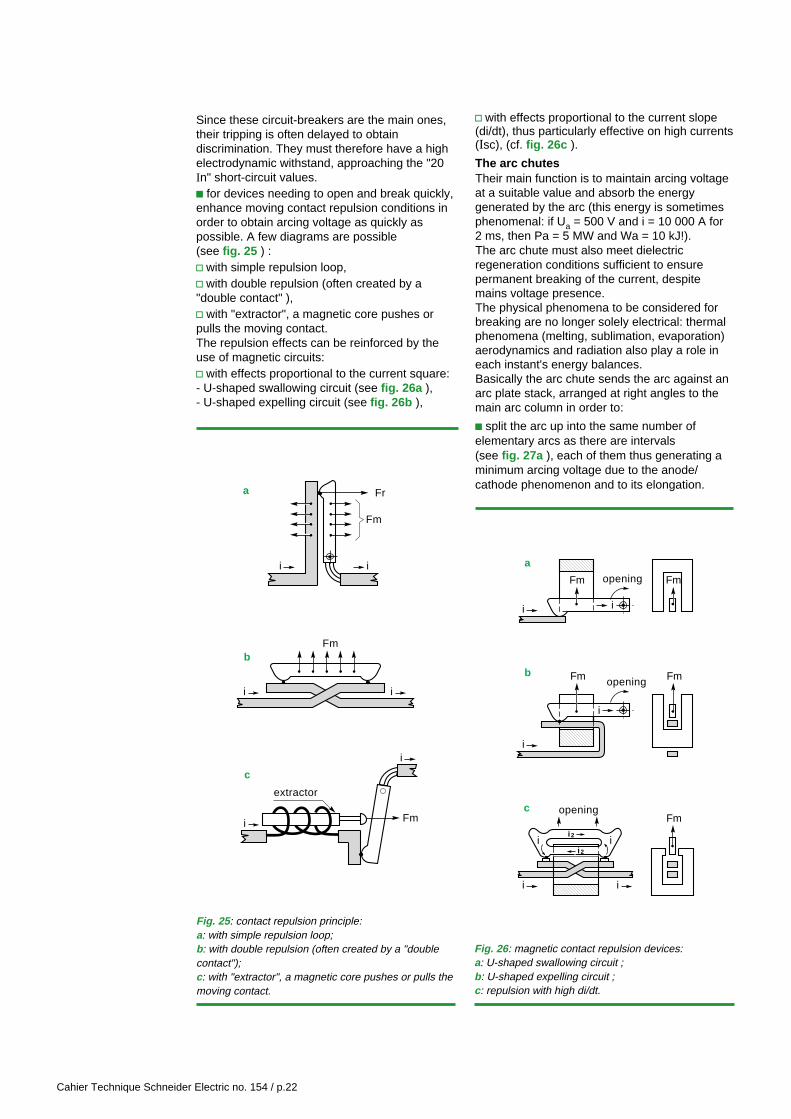
Since these circuit-breakers are the main ones,their tripping is often delayed to obtaindiscrimination. They must therefore have a highelectrodynamic withstand, approaching the "20In" short-circuit values.c for devices needing to open and break quickly,enhance moving contact repulsion conditions inorder to obtain arcing voltage as quickly aspossible. A few diagrams are possible(see fig. 25 ) :v with simple repulsion loop,v with double repulsion (often created by a"double contact" ),v with "extractor", a magnetic core pushes orpulls the moving contact.The repulsion effects can be reinforced by theuse of magnetic circuits:v with effects proportional to the current square:- U-shaped swallowing circuit (see fig. 26a ),- U-shaped expelling circuit (see fig. 26b ),
Fig. 26 : magnetic contact repulsion devices:a: U-shaped swallowing circuit ;b: U-shaped expelling circuit ;c: repulsion with high di/dt.
i
Fm
Fm
i
Fm
i i
i
i
extractor
Fr
b
a
c
v with effects proportional to the current slope(di/dt), thus particularly effective on high currents(Isc), (cf. fig. 26c ).
The arc chutesTheir main function is to maintain arcing voltageat a suitable value and absorb the energygenerated by the arc (this energy is sometimesphenomenal: if Ua = 500 V and i = 10 000 A for2 ms, then Pa = 5 MW and Wa = 10 kJ!).The arc chute must also meet dielectricregeneration conditions sufficient to ensurepermanent breaking of the current, despitemains voltage presence.The physical phenomena to be considered forbreaking are no longer solely electrical: thermalphenomena (melting, sublimation, evaporation)aerodynamics and radiation also play a role ineach instant's energy balances.Basically the arc chute sends the arc against anarc plate stack, arranged at right angles to themain arc column in order to:
c split the arc up into the same number ofelementary arcs as there are intervals(see fig. 27a ), each of them thus generating aminimum arcing voltage due to the anode/cathode phenomenon and to its elongation.
�����
������
��
���
��
b
a
c
Fm
Fm
Fm
i
i
i
i
Fm opening
ii
i i
i 2
i 2
opening
openingFm

Cahier Technique Schneider Electric no. 154 / p.23
Arcing voltage when splitting occurs is calculatedas follows:Ua ≈ N x UAC + (L - N e) ULFor example: where N = 10, L = 4 cm,e = 2 mm, UAC = 30 V and UL = 75 V/cmUa = 200 + 150 = 350 V
c store, by temperature rise or temporary arcplate melting, the energy produced under highcurrents in the plasma column. In actual fact, inparticular situations, there is an upper currentlimit beyond which the arc remains in front of thearc plate stack, (see fig. 27b ), while continuingto exchange considerable heat with them .Although the arc is no longer split, arcing voltagehas the same magnitude.
The zone before chuteThis zone is made up of the volumeseparating the contact separation zone andthe beginning of the arc plates making up thearc chute.Specific precautions must be taken to:
c prevent the arc stagnating on the contacts.The «lower» arc runner helps by moving thefixed contact arc foot underneath the chute arcplates;
c promote faster and more extensive arcelongation than that caused by simplemechanical opening of the contacts.
The magnetic effects, already mentioned formoving contact repulsion, will help by acting onthe arcing current.
In addition to this «magnetic blowing», a realaerodynamic blowing will occur if the energy ofthe emerging arc vaporises or sublimatesablative materials by generating overpressuresand gases which enhance arcing voltageevolution.
Also should be mentioned the inevitablepressure when interrupting high currents in aconfined surrounding. This favours thedevelopment of arc voltage, because:
c the section on the right of the arc column isreduced, and its resistance increased;
c pressure differences between this area(overpressure due to the arc) and the rearside of the arc chute (atmospheric pressure)favours its penetration and confinement in thearc chute.
Fig. 27 : the arc plates placed in the arc chutes help to extinguish the arc.
LN
e
e
e ⇒
a
i
movingcontact
b
Cahier Technique Schneider Electric no. 154 / p.24
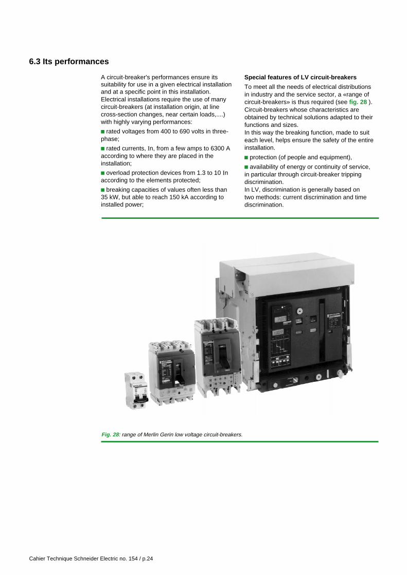
Special features of LV circuit-breakers
To meet all the needs of electrical distributionsin industry and the service sector, a «range ofcircuit-breakers» is thus required (see fig. 28 ).Circuit-breakers whose characteristics areobtained by technical solutions adapted to theirfunctions and sizes.In this way the breaking function, made to suiteach level, helps ensure the safety of the entireinstallation.
c protection (of people and equipment),
c availability of energy or continuity of service,in particular through circuit-breaker trippingdiscrimination.In LV, discrimination is generally based ontwo methods: current discrimination and timediscrimination.
A circuit-breaker's performances ensure itssuitability for use in a given electrical installationand at a specific point in this installation.Electrical installations require the use of manycircuit-breakers (at installation origin, at linecross-section changes, near certain loads,....)with highly varying performances:
c rated voltages from 400 to 690 volts in three-phase;
c rated currents, In, from a few amps to 6300 Aaccording to where they are placed in theinstallation;
c overload protection devices from 1.3 to 10 Inaccording to the elements protected;
c breaking capacities of values often less than35 kW, but able to reach 150 kA according toinstalled power;
Fig. 28 : range of Merlin Gerin low voltage circuit-breakers.
6.3 Its performances

Cahier Technique Schneider Electric no. 154 / p.25
c the former, reinforced by use of energydiscrimination (refer to "Cahier Technique" no.167) is obtained with A category circuit-breakersas in standard IEC 60947-2. These circuit-breakers have to break the fault current veryquickly and considerably limit short-circuitcurrents.
c the latter is achieved with B category circuit-breakers. These circuit-breakers, normally themain ones, have to withstand the flow of steady-state fault currents and therefore need anexcellent electrodynamic withstand.
Fig. 29 : breaking unit of a rotating contact LV circuit-breaker (Compact NS - Merlin Gerin).
Excellent short-circuit current limitation(also refer to "Cahier Technique" no. 163)This is particularly aimed at for circuit-breakersless than or equal to 630 A.These circuit-breakers develop an arcing voltageof 600 to 900 V in small volumes. It is easier toobtain this voltage using double breakingsystems (by combining the diagrams in figures25b and 26b) and by implementing a rotatingtype moving contact which has the addedadvantage of simplifying production of onebreaking unit per pole (see fig. 29 ).
$$$%%%&&&''(())**++,,--..//00112233444555
�����������
$$%%&&''()*+,--../0122334455667899::;;<<==>>?@AABBCCDDEEFFGHHIIJJKKLLMMNOP
��
�����
�����
������
����
�������
���
��������
��
��������
������
�����
�����
�������
����
��������
������������������
HHIIJJJKKKLLLMMMNNNOOPP
��������� ������������ ��
�� ���������
������ ���������������� ������������������� �������������� �� �
�������������������������������������������������������������������������������
������������������
--..//00112234566778899::;;<<==>>??@@AAABBCCDDEEFFGGHHHIIJJKKLLMMNNOOPP��
connection trip unit
magnetic circuit
bar
enclosure
moving contact
ablative part
arc chute
upper connection
##$$%%&&''(())**++,,--..//00
��
���� ���������� <=>?EFGHIJJKKLMNOPQRSTUVWXYZ[[\\]̂_̀`aabcdefghijk

Cahier Technique Schneider Electric no. 154 / p.26
Fig. 30 : breaking unit of a LV circuit-breaker with excellent electrodynamic withstand (Masterpact - Merlin Gerin).
It is thus possible to break 100 kA in 2.5 msusing a 250 A circuit-breaker.
Excellent electrodynamic withstandThis is aimed at for circuit-breakers equal to orgreater than 800 A.
This aim requires compensation ofelectromagnetic forces, which is easier to achievewith simple breaking (diagram 24b) all the moreso since the wide opening (distance betweencontacts) of these larger devices (importance ofconductive parts for high current flow) alsoenables a high arcing voltage (600 to 900 V) tobe obtained.
A 3200 A circuit-breaker thus breaks "100 kA" in15 ms (without tripping delay) as well aswithstanding 75 kA for 3 s (see. fig. 30 ).
Proven performancesCircuit-breaker performances are evaluated andguaranteed by the carrying out of standardizedtests (refer to IEC 60947-2 and NF C 63-120 ).
Thus, with respect to "breaking", tests are usedto verify for example:
c endurances under In,
c overload endurances (e.g. under 6 In),
c breaking capacities by cycles :v O-FO at Icu, ultimate breaking capacity,v or O-FO -FO at Ics, service breaking capacitywith Ics ≤ Icu.
Note:The publication of standard IEC 60947-2,dealing with industrial LV circuit-breakers, is thesubject of "Cahier Technique" no. 150 whichcompletes the details given above.
lowerterminal
�����������
���������������###$$$%%%&&&''(())**++,,,---...///000
���������������
�������������**+++,,,---..//00
������������� ������ �������������������������
�������������������������
��������
��������������###$$$%%%&&&''(())66778899:::;;;<<<===>>>
���������������������
����
�����������
�������������������
��������������� ����������������������������������
�������������**++,,---...///000
������������
��������
��������������
������
������������� ���
������������arc chute
poles shaftactivated by theO-CO mechanism
insulatingpole cage
arcing horn
upperterminal
Ag based maincontacts
temporarycontacts
current transformerconnected to electronic trip unit
Cahier Technique Schneider Electric no. 154 / p.27
7 Conclusion
Bibliography
The future of the arc?
The electric arc continues to be an excellentmeans of breaking with current limitation in lowvoltage.Moreover, low voltage circuit-breakers havebeen considerably enhanced as a result ofdevelopments in know-how, materials and use ofelectronics.For many decades to come, electric circuitprotection will therefore continue to requirecircuit-breakers with «arc control».
Standards
c IEC 60947-2: Low-voltage switchgear - Part 2:circuit-breakers.
c IEC 60050: International electrotechnicalvocabulary.
c NF C 63-120 (French Standards): Appareillageà basse tension - 2ème partie : disjoncteurs.
Cahiers Techniques Schneider Electric
c Development of LV circuit-breakers tostandard IEC 947-2.Cahier Technique no. 150E. BLANC
c LV breaking by current limitation.Cahier Technique no. 163P. SCHUELLER
c Energy based discrimination for low voltageprotective devices.Cahier Technique no. 167R. MOREL - M. SERPINET


Schneider Electric Direction Scientifique et Technique,Service Communication TechniqueF-38050 Grenoble cedex 9Fax : (33) 04 76 57 98 60
DTP : AK.Edition : Schneider ElectricPrinting : Imprimerie du Pont de Claix - Claix - 1000.- 100 FF- ©
200
0 S
chne
ider
Ele
ctric
06-200063577