low-voltage cutoff switch - jameco electronics · pdf filea microcontroller-based voltage...
TRANSCRIPT
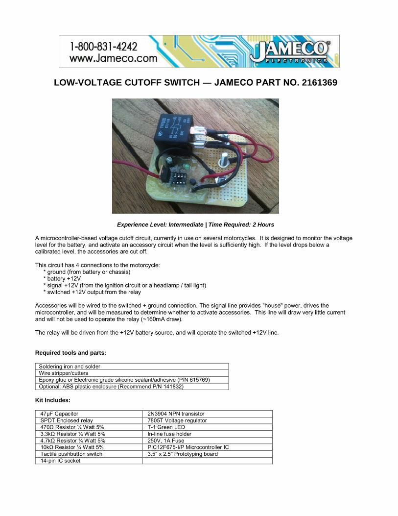
LOW-VOLTAGE CUTOFF SWITCH ― JAMECO PART NO. 2161369
Experience Level: Intermediate | Time Required: 2 Hours
A microcontroller-based voltage cutoff circuit, currently in use on several motorcycles. It is designed to monitor the voltage level for the battery, and activate an accessory circuit when the level is sufficiently high. If the level drops below a calibrated level, the accessories are cut off. This circuit has 4 connections to the motorcycle: * ground (from battery or chassis) * battery +12V * signal +12V (from the ignition circuit or a headlamp / tail light) * switched +12V output from the relay Accessories will be wired to the switched + ground connection. The signal line provides "house" power, drives the microcontroller, and will be measured to determine whether to activate accessories. This line will draw very little current and will not be used to operate the relay (~160mA draw). The relay will be driven from the +12V battery source, and will operate the switched +12V line. Required tools and parts:
Soldering iron and solder Wire stripper/cutters Epoxy glue or Electronic grade silicone sealant/adhesive (P/N 615769) Optional: ABS plastic enclosure (Recommend P/N 141832)
Kit Includes:
47μF Capacitor 2N3904 NPN transistor SPDT Enclosed relay 7805T Voltage regulator 470Ω Resistor ¼ Watt 5% T-1 Green LED 3.3kΩ Resistor ¼ Watt 5% In-line fuse holder 4.7kΩ Resistor ¼ Watt 5% 250V, 1A Fuse 10kΩ Resistor ¼ Watt 5% PIC12F675-I/P Microcontroller IC Tactile pushbutton switch 3.5" x 2.5" Prototyping board 14-pin IC socket
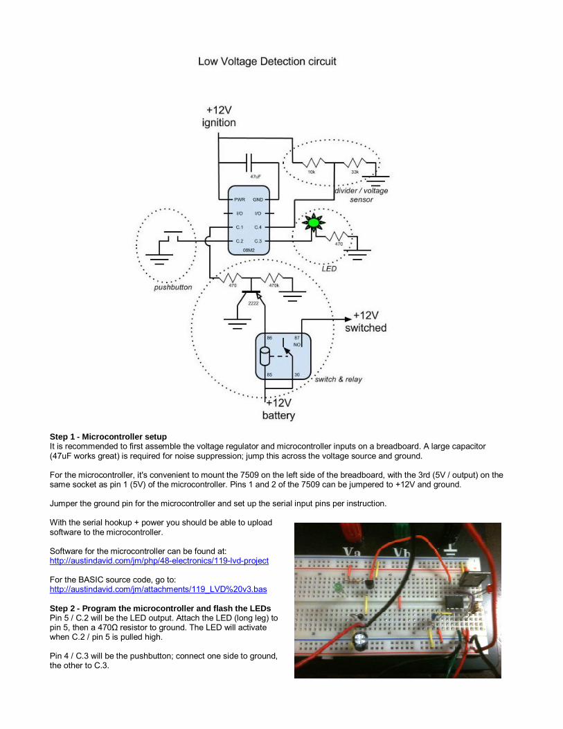
Step 1 - Microcontroller setup It is recommended to first assemble the voltage regulator and microcontroller inputs on a breadboard. A large capacitor (47uF works great) is required for noise suppression; jump this across the voltage source and ground. For the microcontroller, it's convenient to mount the 7509 on the left side of the breadboard, with the 3rd (5V / output) on the same socket as pin 1 (5V) of the microcontroller. Pins 1 and 2 of the 7509 can be jumpered to +12V and ground. Jumper the ground pin for the microcontroller and set up the serial input pins per instruction. With the serial hookup + power you should be able to upload software to the microcontroller. Software for the microcontroller can be found at: http://austindavid.com/jm/php/48-electronics/119-lvd-project For the BASIC source code, go to: http://austindavid.com/jm/attachments/119_LVD%20v3.bas Step 2 - Program the microcontroller and flash the LEDs Pin 5 / C.2 will be the LED output. Attach the LED (long leg) to pin 5, then a 470Ω resistor to ground. The LED will activate when C.2 / pin 5 is pulled high. Pin 4 / C.3 will be the pushbutton; connect one side to ground, the other to C.3.

The running program will flash the LED regularly depending on voltage level. Press and hold the pushbutton to enter calibration (and flash the LED); continue to hold and the part will reset, with the LED flashing fast for a second. Step 3 - Voltage input - measuring voltage on the ADC For bench testing a 10kΩ pot works great - jump the outside pins to ground and +12V, and use the inside / variable pin for the ADC input on C.1 (pin 6). In production, use a 33k down to ground, and a 10k up to +12V. This will divide the variable source (which can range from 12-15V or higher) down a level measurable by the ADC. The actual values will be calibrated after the part is installed. With the pot installed, measure the output voltage; shoot for about 3.5V. The part will flash the LED quickly, indicating that it sees low voltage / is monitoring for a high voltage condition. Increase the voltage at the pot; as it crosses the high-water mark the LED will flash slower. In verbose mode the program will also output recorded values over the serial output. Step 4 - Switching transistor Mock up the transistor circuit, verify all functionality. Pin 3 / C.4 is the switched output. Connect this pin to a 470Ω resistor, then to the center of the switching transistor. Use a 47kΩ pulldown resistor on this pin as well. Ground the appropriate side, and the last pin (emitter) serves as the ground side of the relay control. Wire the relay: one side of the switch goes to the +12V source. Briefly connect the other side of the relay to ground to verify operation. Connect this end to the emitter on the transistor. Jump the transistor input's 470Ω resistor to +5V, and confirm that the relay trips. At this point the transistor should be pulling the relay to ground, closing its circuit. Reconnect the transistor circuit correctly. Drop the input voltage and observe the LED flashing quickly and the relay "off". Raise the voltage above the water mark and observe the relay activating and the LED flashing slowly. Press and hold the switch to enter calibration mode, and the relay will automatically activate as the microcontroller attempts to test the voltage in a high-drain condition. Step 5 - Mount all components on a PCB The 14-pin socket will house the 8-pin part (mounted in the "top" at pin1), the 3-pin transistor in socket pins 5-7. You can use the last 3 open pins (8-10) for available serial ports for future debugging or software updates. Use long 18 AWG primary wire for the two "house" inputs, and the two outputs to drive the relay. The house inputs will attach to the appropriate bus lines of the PCB. The divider circuit will attach directly to ground and +12V. The LED + resistor will attach to ground. The pushbutton will attach to +12V. One leg of the resistor (socket pin 5) will attach to ground. The 7805 regulator and capacitor will each have pins on both ground and +12V. The relay inputs will use +12V (which should come directly from the battery, not from the "house" signal line) and the transistor output on socket pin 7. The serial input pins for PIC microcontroller will be grounded, divided to ground, or jumped to socket pin 13 respectively. The two "house" inputs: the signal line will go to a headlamp or ignition source, so leave it very long. The ground line can connect directly to one of the 3 terminals to be created later (battery ground). The transistor circuit will connect to one end of the relay, and the other side of the relay will connect to the battery +12V (another of the 3 terminals).
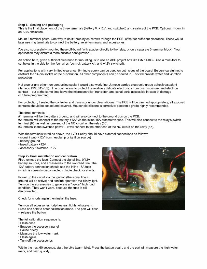
Step 6 - Sealing and packaging This is the final placement of the three terminals (battery 0, +12V, and switched) and sealing of the PCB. Optional: mount in an ABS enclosure. Mount 3 terminal posts. One way to do it: three nylon screws through the PCB, offset for sufficient clearance. These would later use ring terminals to connect the battery, relay terminals, and accessories. I've also successfully mounted these off-board (with spades directly to the relay, or on a separate 3-terminal block). Your application may dictate a more suitable configuration. An option here, given sufficient clearance for mounting, is to use an ABS project box like P/N 141832. Use a multi-tool to cut holes in the side for the four wires (control, battery +/-, and +12V switched). For applications with very limited clearance, 5-minute epoxy can be used on both sides of the board. Be very careful not to obstruct the 14-pin socket or the pushbutton. All other components can be sealed in. This will provide water and vibration protection. Hot glue or any other non-conducting sealant would also work fine. Jameco carries electronic-grade adhesive/sealant(Jameco P/N: 615769). The goal here is to protect the relatively delicate electronics from dust, moisture, and electrical contact -- but at the same time leave the microcontroller, transistor, and serial ports accessible in case of damage or future programming. For protection, I sealed the controller and transistor under clear silicone. The PCB will be trimmed appropriately; all exposed contacts should be sealed and covered. Household silicone is corrosive; electronic grade highly recommended. The three terminals: #1 terminal will be the battery ground, and will also connect to the ground bus on the PCB. #2 terminal will connect to the battery +12V via the inline 15A automotive fuse. This will also connect to the relay's switch terminal (85) as well as one end of the NO circuit on the relay (30). #3 terminal is the switched power -- it will connect to the other end of the NO circuit on the relay (87). With the terminals wired as above, the LVD + relay should have external connections as follows: - signal input (+12V from headlamp or ignition source) - battery ground - fused battery +12V - accessory / switched +12V Step 7 - Final installation and calibration First, remove the fuse. Connect the signal line, 0/12V battery sources, and accessories to the switched line. The 12V battery connection should use the inline 15A fuse (which is currently disconnected). Triple check for shorts. Power up the circuit via the ignition (the signal line + ground will be active) and confirm operation via blinky light. Turn on the accessories to generate a "typical" high load condition. They won't work, because the fuse is still disconnected. Check for shorts again then install the fuse. Turn on all accessories (grip heaters, lights, whatever). Press and hold to enter calibration mode. The part will flash -- release the button. The full calibration sequence is: • Flash once • Engage the accessory panel • Pause briefly • Measure the low water mark • Flash again • Turn off the accessories Within the next 60 seconds, start the bike (warm idle). Press the button again, and the part will measure the high water mark, and flash quickly.
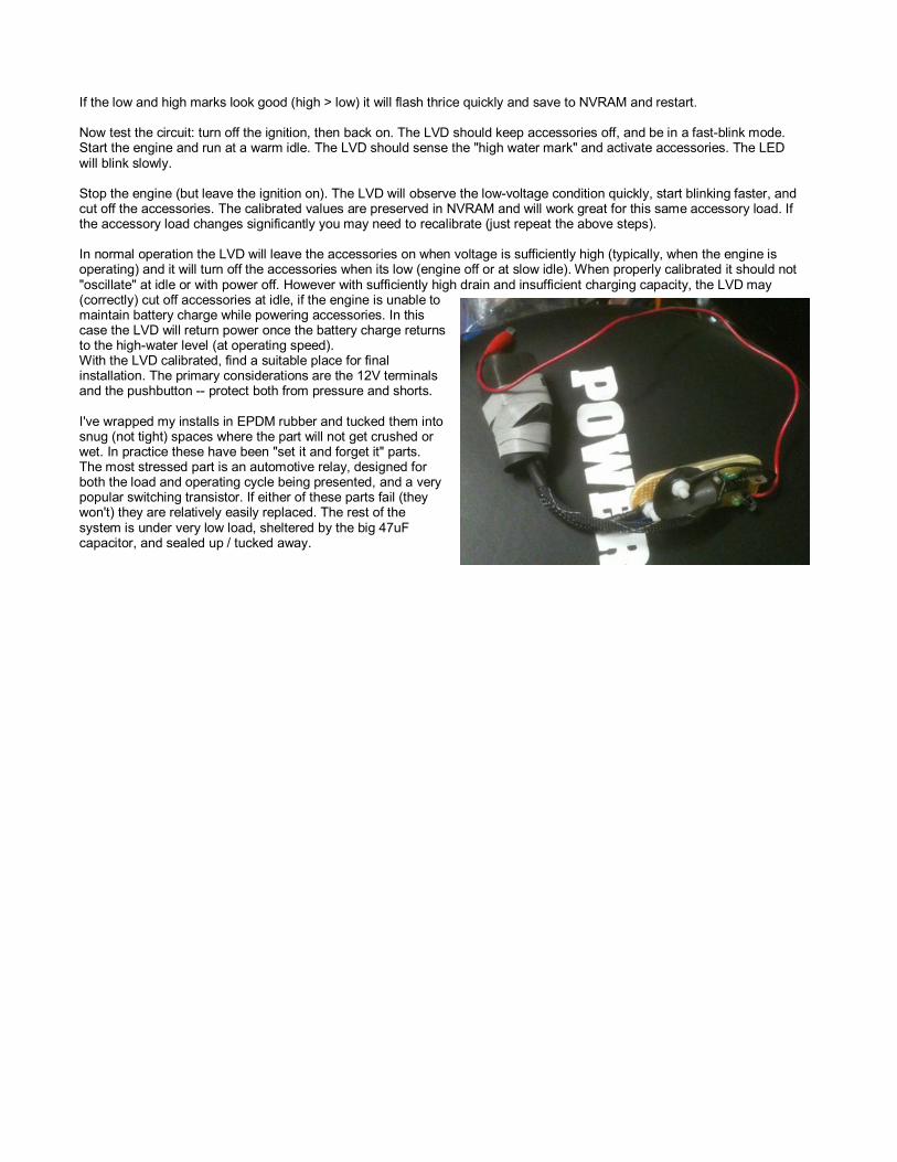
If the low and high marks look good (high > low) it will flash thrice quickly and save to NVRAM and restart. Now test the circuit: turn off the ignition, then back on. The LVD should keep accessories off, and be in a fast-blink mode. Start the engine and run at a warm idle. The LVD should sense the "high water mark" and activate accessories. The LED will blink slowly. Stop the engine (but leave the ignition on). The LVD will observe the low-voltage condition quickly, start blinking faster, and cut off the accessories. The calibrated values are preserved in NVRAM and will work great for this same accessory load. If the accessory load changes significantly you may need to recalibrate (just repeat the above steps). In normal operation the LVD will leave the accessories on when voltage is sufficiently high (typically, when the engine is operating) and it will turn off the accessories when its low (engine off or at slow idle). When properly calibrated it should not "oscillate" at idle or with power off. However with sufficiently high drain and insufficient charging capacity, the LVD may (correctly) cut off accessories at idle, if the engine is unable to maintain battery charge while powering accessories. In this case the LVD will return power once the battery charge returns to the high-water level (at operating speed). With the LVD calibrated, find a suitable place for final installation. The primary considerations are the 12V terminals and the pushbutton -- protect both from pressure and shorts. I've wrapped my installs in EPDM rubber and tucked them into snug (not tight) spaces where the part will not get crushed or wet. In practice these have been "set it and forget it" parts. The most stressed part is an automotive relay, designed for both the load and operating cycle being presented, and a very popular switching transistor. If either of these parts fail (they won't) they are relatively easily replaced. The rest of the system is under very low load, sheltered by the big 47uF capacitor, and sealed up / tucked away.