low voltage electrical distribution masterpact nt and · pdf filemasterpact nt and nw circuit...
TRANSCRIPT
MasterpactNT and NWCircuit breakers and switch-disconnectors
Low voltage electrical distribution
Maintenance guide11/2008
LVPED508016EN_couv.indd 1 25/11/2008 15:45:01
Thank you for purchasing a Merlin Gerin protection device.To maintain the device's operating and safety characteristics as they are indicated in the catalogue from the beginning to the end of the product's service life, Schneider Electric recommends that systematic checks and periodic maintenance be carried out by qualified personnel, as indicated in this "Masterpact maintenance".Please read this document carefully and keep it at hand, near the device.It provides detailed information on:
the various types of maintenance required, depending on the criticality of the protected circuit.
what must receive maintenance.the risks involved if the component ceases to operate correctly.what is understood by the terms normal, improved and severe environment and
operating conditions.the periodic preventive maintenance operations that should be carried out under
normal environment and operating conditions as well as the level of competence required for the operations.
the environment and operating conditions that accelerate device ageing.the limits governing use of mechanical and electric accessories and
subassemblies.finally, all the product guides available in order to maintain the device in proper
operating condition.The level II and III procedures mentioned in this guide may be obtained on request from the Schneider Electric after-sales support department.
b
bbb
b
bb
b
This guide is intended primarily for qualified personnel in charge of equipment maintenance and for Schneider Electric after-sales support personnel for the information on system diagnostics.
LVPED508016EN_couv.indd 2 25/11/2008 15:45:01
Maintenance guide for circuit breakers and switch-disconnector Masterpact NT and NW
�LVPED5080�6EN - ��/2008
Contents
The different types of maintenance 2Corrective maintenance 2Preventive maintenance 2Predictive maintenance 3Masterpact NT and NW What must be maintained and why? 4The case 4Arc chutes 4Main contacts 4Device and chassis mechanisms 5Auxiliary circuits 6Electronic trip unit 7Communication module and accessories 7Connections 8Recommended preventive maintenance and time intervals 9Normal conditions 9Favourable conditions or device protected �0Severe conditions and device not protected �0Device check-up ��Check after prolonged storage ��Level II preventive maintenance recommended every year 12Level III preventive maintenance recommended every 2 years 13Level IV manufacturer diagnostic and replacement of components recommended every 5 years 14Causes of accelerated ageing 15Influence of the environment 15Ambient temperature (outside the switchboard) �5Percent load (I/In) �6Relative humidity �7Salt environment �8Harmonics �9Dust 20Corrosive atmosphere 2�Environment categories as per standard 72�-3-3 2�Operating conditions 22Vibrations 22Number of operating cycles 22Interrupted current 23Operating limits 24List of available guides 25Switchgear guides 25Troubleshooting and solutions 26
LVPED508016ENp1_p28.indd 1 25/11/2008 15:46:07

2 LVPED5080�6EN - ��/2008
Masterpact NT and NW Maintenance guide
The different types of maintenance
Corrective maintenanceCorrective maintenance repairs a system in view of fulfilling a required function.
Incidents during system start-upMany malfunctions result from non-observance of the start-up instructions or lack of knowledge concerning the equipment and/or switchgear procedures.Schneider Electric operating guides, supplied with products and equipment, contain clear instructions for operators or maintenance personnel on how to correct malfunctions. These instructions are included at the end or this guige.The list of the available operating guides may be found at the end of this document. The PDF files may de downloaded from the www.schneider-electric.com site.
Breakdowns during operationContact the certified maintenance department. The Schneider Electric Service Centres may be contacted via the www.schneider-electric.com site.
Preventive maintenancePreventive maintenance consists in carrying out, at predetermined intervals or according to prescribed criteria, checks intended to reduce the probability of a failure or deterioration in the operation of a system.There are two types of preventive maintenance:
Periodic maintenance For each type of product, maintenance recommendations are laid out by the technical department. These verification procedures, intended to maintain systems or their subassemblies in correct operating condition over the targeted service life, must be carried out according to the time intervals stipulated in this document.Under no circumstances can Schneider Electric be held responsible for any damage caused by the failure of device if the periodic checks were not carried out in accordance with the recommendations in this document.
Conditional maintenanceTo a certain extent, conditional-maintenance operations are a means to reduce (but not eliminate) the recommended periodic-maintenance operations (thus limited to the strict minimum) that require an annual shutdown of the installation.These operations are launched when programmed alarms indicate that a predefined threshold has been reached. To that end, sensors must be installed on the switchgear and in the switchboard. Conditional maintenance is the means to optimise installation maintenance.For more information on the possibilities offered by conditional maintenance, contact your Schneider Electric after-sales support department.
b
b
DB
�200
7�A
LVPED508016ENp1_p28.indd 2 25/11/2008 15:46:08

3LVPED5080�6EN - ��/2008
Masterpact NT and NW Maintenance guide
The different types of maintenance
Predictive maintenancePredictive maintenance, based on the recording and analysis of system parameters, is the means to detect drift from the initial state and significant trends. Using predictive maintenance, the customer can anticipate on the corrective action required to ensure equipment safety and continuity of service, and plan the action for the most convenient time.To ensure the highest possible level of installation reliability and optimise the service life of equipment, it is advised to establish a maintenance plan. The plan indicates for each piece of equipment:
the most suitable type of maintenancethe recommended frequency of maintenance.
The plan is based on two criteria:the criticality of each device in the installationdevice operating conditions.
Criticality depends on the consequences of device failure in terms of the safety of life and property, production losses, the cost of repair and start-up, etc. An empirical estimate may be sufficient for simple cases, but it is recommended to undertake a reliability analysis of the installation for more complex architectures involving backup sources, transfer mechanisms, etc. Check with your Schneider Electric Service Centre for more information.The operating conditions reflect the environment in which the device is installed (relative humidity, heat, dust, etc.) and how the device is used (load, frequency of operation, quality of the supply current, etc.). These conditions are discussed in detail in this document, as well as the ensuing maintenance recommendations.Consequently, for a given device, the recommended maintenance may vary substantially both in terms of the necessary operations and their frequency.
Example of Masterpact predictive maintenance
bb
bb
DB
�0�5
23
Monitoring and recording Goal Tool Service offeredNumber of operating cycles Monitor manufacturer limits and determine the
probable replacement dateElectronic counter with the communication module+ MPS�00 server
Remote monitoring by:customer supervisor or Serenity service (1)
bb
Trip and alarm histories Analyse the distribution-system phenomena that resulted in tripping or alarms caused by transient overloads, setting changes or a modification in the installation
Micrologic P/ H event log+ MPS�00 server
Remote monitoring by:customer supervisor or Serenity service (1)
bb
Contact wear Monitor (without dismantling) the arc chutes on the circuit breakers and plan their replacement
Micrologic P/ H event log+ MPS�00 server
Remote monitoring by:customer supervisor or Serenity service (1)
bb
Percent load Estimate as precisely as possible the probable service life of the device
Remote monitoring by:customer supervisor or Serenity service (1)
bb
Pole opening and closing speed Monitor any mechanical drift in devices and evaluate their condition
Prodiag tester Remote monitoring by:customer supervisor or Serenity service (1)
bb
(1) Serenity is a Schneider Electric service providing installation diagnostics and analysis of distribution systems.
For more information on the possibilities offered by predictive maintenance, contact your Schneider after-sales support department.
LVPED508016ENp1_p28.indd 3 25/11/2008 15:46:09
4 LVPED5080�6EN - ��/2008
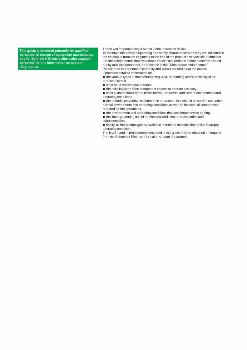
The caseThe case is an essential element in the circuit breaker. First of all, it ensures a number of safety functions:
functional insulation between the phases themselves and between the phases and the exposed conductive parts in order to resist transient overvoltages caused by the distribution system
a barrier avoiding direct user contact with live partsprotection against the effects of electrical arcs and overpressures caused by
short-circuits.Secondly, it serves to support the entire pole operating mechanism as well as the mechanical and electrical accessories of the circuit breaker.On the case, there should be:
no traces of grime (grease), excessive dust or condensation which all reduce insulation
no signs of burns or cracks which would reduce the mechanical solidity of the case and thus its capacity to withstand short-circuits.Preventive maintenance for cases consists of a visual inspection of its condition and cleaning with a dry cloth or a vacuum cleaner. All cleaning products with solvents are strictly forbidden. It is advised to measure the insulation every five years and following trips due to a short-circuit. The case must be replaced if there are signs of burns or cracks.
b
bb
b
b
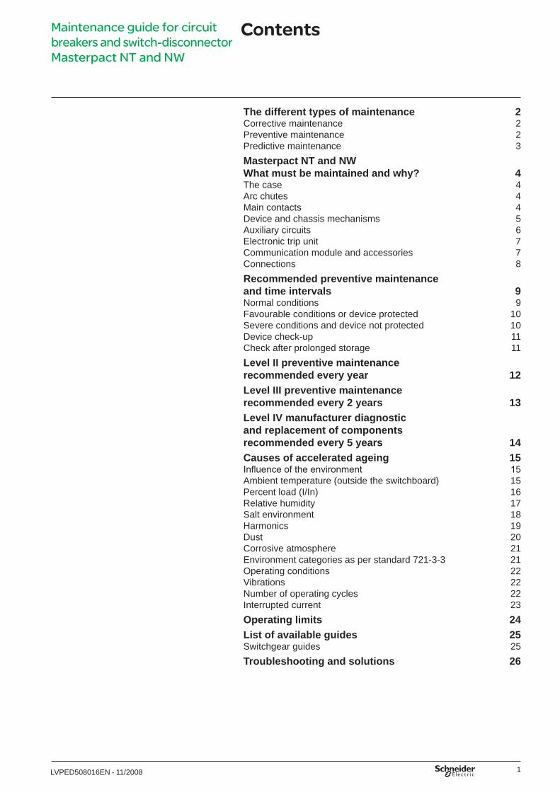
Arc chutesDuring a short-circuit, the arc chute serves to extinguish the arc and to absorb the high level of energy along the entire path of the short-circuit. It also contributes to arc extinction under rated current conditions. An arc chute that is not in good condition may not be capable of fully clearing the short-circuit and ultimately result in the destruction of the circuit breaker. The arc chutes must be regularly checked. The fins of the arc chutes may be blackened (due to the gases produced at In) but must not be significantly damaged. What is more, the filters must not be blocked to avoid internal overpressures. It is advised to use a vacuum cleaner rather than a cloth to remove dust from the outside of the arc chutes.
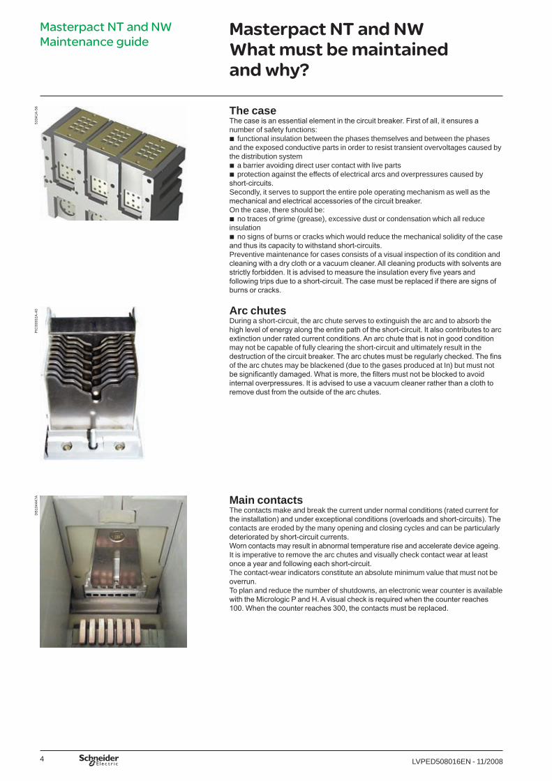
Main contactsThe contacts make and break the current under normal conditions (rated current for the installation) and under exceptional conditions (overloads and short-circuits). The contacts are eroded by the many opening and closing cycles and can be particularly deteriorated by short-circuit currents. Worn contacts may result in abnormal temperature rise and accelerate device ageing.It is imperative to remove the arc chutes and visually check contact wear at least once a year and following each short-circuit.The contact-wear indicators constitute an absolute minimum value that must not be overrun.To plan and reduce the number of shutdowns, an electronic wear counter is available with the Micrologic P and H. A visual check is required when the counter reaches 100. When the counter reaches 300, the contacts must be replaced.
5334
�A-5
6Masterpact NT and NW What must be maintained and why?
Masterpact NT and NW Maintenance guide
PIC
0000
2A-4
0D
B�0
4447
A
LVPED508016ENp1_p28.indd 4 25/11/2008 15:46:10
5LVPED5080�6EN - ��/2008
PB
�007
66A
-56
Masterpact NT and NW What must be maintained and why?
Masterpact NT and NW Maintenance guide
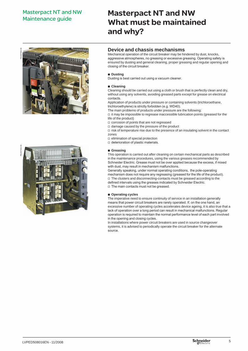
Device and chassis mechanismsMechanical operation of the circuit breaker may be hindered by dust, knocks, aggressive atmospheres, no greasing or excessive greasing. Operating safety is ensured by dusting and general cleaning, proper greasing and regular opening and closing of the circuit breaker.
Dusting Dusting is best carried out using a vacuum cleaner.
Cleaning Cleaning should be carried out using a cloth or brush that is perfectly clean and dry, without using any solvents, avoiding greased parts except for grease on electrical contacts.Application of products under pressure or containing solvents (trichloroethane, trichloroethylene) is strictly forbidden (e.g. WD40). The main problems of products under pressure are the following:
it may be impossible to regrease inaccessible lubrication points (greased for the life of the product)
corrosion of points that are not regreaseddamage caused by the pressure of the productrisk of temperature rise due to the presence of an insulating solvent in the contact
zoneselimination of special protectiondeterioration of plastic materials.
GreasingThis operation is carried out after cleaning on certain mechanical parts as described in the maintenance procedures, using the various greases recommended by Schneider Electric. Grease must not be over applied because the excess, if mixed with dust, may result in mechanism malfunctions.Generally speaking, under normal operating conditions, the pole-operating mechanism does not require any regreasing (greased for the life of the product).
The clusters and disconnecting-contacts must be greased according to the defined intervals using the greases indicated by Schneider Electric.
The main contacts must not be greased.
Operating cyclesThe imperative need to ensure continuity of service in an installation generally means that power circuit breakers are rarely operated. If, on the one hand, an excessive number of operating cycles accelerates device ageing, it is also true that a lack of operation over a long period can result in mechanical malfunctions. Regular operation is required to maintain the normal performance level of each part involved in the opening and closing cycles.In installations where power circuit breakers are used in source changeover systems, it is advised to periodically operate the circuit breaker for the alternate source.
b
b
v
vvv
vv
b
v
v
b
PB
�007
64A
-56
LVPED508016ENp1_p28.indd 5 25/11/2008 15:46:11
6 LVPED5080�6EN - ��/2008
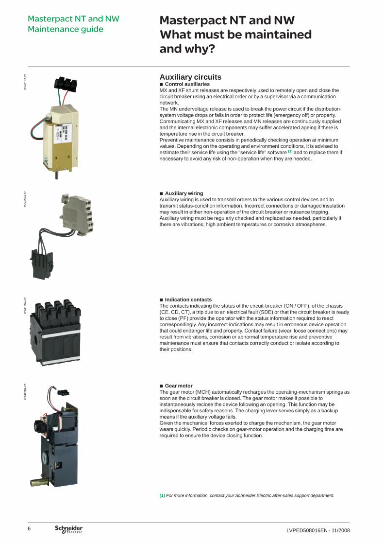
Auxiliary circuitsControl auxiliaries
MX and XF shunt releases are respectively used to remotely open and close the circuit breaker using an electrical order or by a supervisor via a communication network. The MN undervoltage release is used to break the power circuit if the distribution-system voltage drops or fails in order to protect life (emergency off) or property.Communicating MX and XF releases and MN releases are continuously supplied and the internal electronic components may suffer accelerated ageing if there is temperature rise in the circuit breaker. Preventive maintenance consists in periodically checking operation at minimum values. Depending on the operating and environment conditions, it is advised to estimate their service life using the "service life" software (1) and to replace them if necessary to avoid any risk of non-operation when they are needed.
b
Auxiliary wiringAuxiliary wiring is used to transmit orders to the various control devices and to transmit status-condition information. Incorrect connections or damaged insulation may result in either non-operation of the circuit breaker or nuisance tripping. Auxiliary wiring must be regularly checked and replaced as needed, particularly if there are vibrations, high ambient temperatures or corrosive atmospheres.
b
Indication contactsThe contacts indicating the status of the circuit-breaker (ON / OFF), of the chassis (CE, CD, CT), a trip due to an electrical fault (SDE) or that the circuit breaker is ready to close (PF) provide the operator with the status information required to react correspondingly. Any incorrect indications may result in erroneous device operation that could endanger life and property. Contact failure (wear, loose connections) may result from vibrations, corrosion or abnormal temperature rise and preventive maintenance must ensure that contacts correctly conduct or isolate according to their positions.
b
Gear motorThe gear motor (MCH) automatically recharges the operating-mechanism springs as soon as the circuit breaker is closed. The gear motor makes it possible to instantaneously reclose the device following an opening. This function may be indispensable for safety reasons. The charging lever serves simply as a backup means if the auxiliary voltage fails.Given the mechanical forces exerted to charge the mechanism, the gear motor wears quickly. Periodic checks on gear-motor operation and the charging time are required to ensure the device closing function.
b
0564
2�N
A-2
905
6455
NA
-37
0564
�9N
A-3
005
6420
NA
-29
(1) For more information, contact your Schneider Electric after-sales support department.
Masterpact NT and NW What must be maintained and why?
Masterpact NT and NW Maintenance guide
LVPED508016ENp1_p28.indd 6 25/11/2008 15:46:12
7LVPED5080�6EN - ��/2008
0564
90A
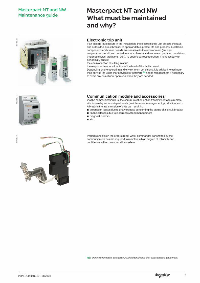
-58 Electronic trip unit
If an electric fault occurs in the installation, the electronic trip unit detects the fault and orders the circuit breaker to open and thus protect life and property. Electronic components and circuit boards are sensitive to the environment (ambient temperature, humid and corrosive atmospheres) and to severe operating conditions (magnetic fields, vibrations, etc.). To ensure correct operation, it is necessary to periodically check:the chain of action resulting in a tripthe response time as a function of the level of the fault current.Depending on the operating and environment conditions, it is advised to estimate their service life using the "service life" software (1) and to replace them if necessary to avoid any risk of non-operation when they are needed.
Communication module and accessoriesVia the communication bus, the communication option transmits data to a remote site for use by various departments (maintenance, management, production, etc.). A break in the transmission of data can result in:
production losses due to unawareness concerning the status of a circuit breakerfinancial losses due to incorrect system managementdiagnostic errorsetc.
bbbb
Periodic checks on the orders (read, write, commands) transmitted by the communication bus are required to maintain a high degree of reliability and confidence in the communication system.
Masterpact NT and NW What must be maintained and why?
(1) For more information, contact your Schneider Electric after-sales support department.
PB
�008
02A
-24
0564
6�N
A-5
6
Masterpact NT and NW Maintenance guide
LVPED508016ENp1_p28.indd 7 25/11/2008 15:46:13
8 LVPED5080�6EN - ��/2008
P42
7002
A-2
8Masterpact NT and NW What must be maintained and why?
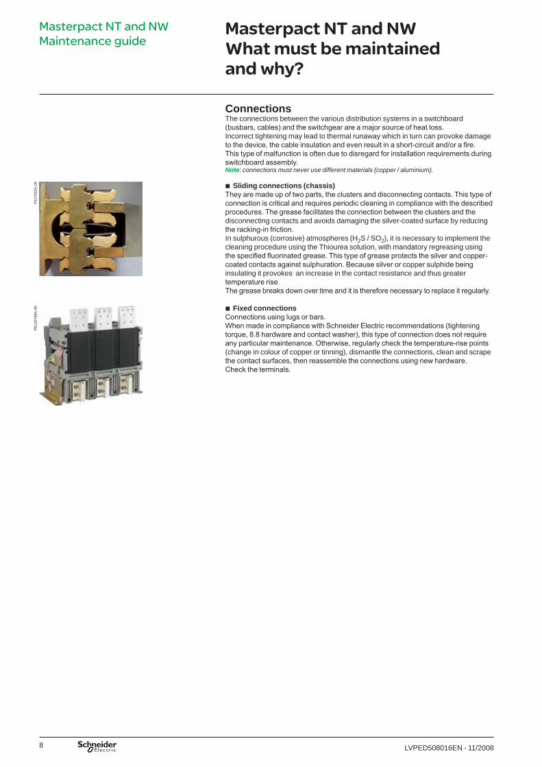
ConnectionsThe connections between the various distribution systems in a switchboard (busbars, cables) and the switchgear are a major source of heat loss.Incorrect tightening may lead to thermal runaway which in turn can provoke damage to the device, the cable insulation and even result in a short-circuit and/or a fire. This type of malfunction is often due to disregard for installation requirements during switchboard assembly.Note: connections must never use different materials (copper / aluminium).
Sliding connections (chassis) They are made up of two parts, the clusters and disconnecting contacts. This type of connection is critical and requires periodic cleaning in compliance with the described procedures. The grease facilitates the connection between the clusters and the disconnecting contacts and avoids damaging the silver-coated surface by reducing the racking-in friction.In sulphurous (corrosive) atmospheres (H2S / SO2), it is necessary to implement the cleaning procedure using the Thiourea solution, with mandatory regreasing using the specified fluorinated grease. This type of grease protects the silver and copper-coated contacts against sulphuration. Because silver or copper sulphide being insulating it provokes an increase in the contact resistance and thus greater temperature rise.The grease breaks down over time and it is therefore necessary to replace it regularly.
Fixed connectionsConnections using lugs or bars.When made in compliance with Schneider Electric recommendations (tightening torque, 8.8 hardware and contact washer), this type of connection does not require any particular maintenance. Otherwise, regularly check the temperature-rise points (change in colour of copper or tinning), dismantle the connections, clean and scrape the contact surfaces, then reassemble the connections using new hardware.Check the terminals.
b
b
PB
�007
86A
-40
Masterpact NT and NW Maintenance guide
LVPED508016ENp1_p28.indd 8 25/11/2008 15:46:13

9LVPED5080�6EN - ��/2008
Recommended preventive maintenance and time intervals
Normal conditionsThe maintenance guide (1) that must be carried out every one, two or five years on Masterpact NT/NW subassemblies and the level of competence required on the part of service agents are described in the tables on pages 12, 13 and 14.At the end of each five year period, the maintenance guide must be systematically repeated.These maintenance operations apply for normal operating and environment conditions as defined below.
Normal operating and environment conditionsTemperature Average annual temperature < 25 °C outside the switchboard
(Ta (1))Percent load < 80 % of In 24/24 hours Harmonics Harmonic current per phase < 30 % of In Relative humidity < 70 %Corrosive atmosphere Device installed in environment category 3C� or 3C2
(IEC 6072�-3-3)Salt environment No salt mistDust Low level
Device protected in switchboard equipped with filters or ventilated IP54 enclosure
Vibration Permanent vibration < 0.2 g
Beyond the above limits, the circuit breakers suffer accelerated ageing that may rapidly result in malfunctions. For this reason, periodic checks must be carried out at shorter time intervals. On the other hand, when special efforts are made to improve the operating and environment conditions, the preventive-maintenance operations can be carried out less often.
(1) The Masterpact maintenance guide is taken into account by the Schneider Electric CamSoft software.Example of a maintenance plan managed by CamSoft.
DB
�044
48A
-�03
Masterpact NT and NW Maintenance guide
LVPED508016ENp1_p28.indd 9 25/11/2008 15:46:14
�0 LVPED5080�6EN - ��/2008
Recommended preventive maintenance and time intervals
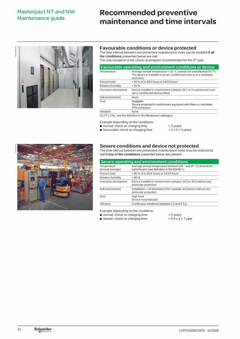
Favourable conditions or device protected The time interval between two preventive-maintenance visits can be doubled if all the conditions presented below are met.The only exception is the check-up program recommended for the 5th year.
Favourable operating and environment conditions or device Temperature Average annual temperature < 25 °C outside the switchboard (Ta (1)).
The device is installed in an air-conditioned room or in a ventilated enclosure
Percent load < 50 % of In 8/24 hours or 24/24 hoursRelative humidity < 50 %Corrosive atmosphere Device installed in environment category 3C� or in a protected room
(air is conditioned and purified)Salt environment NoneDust Negligible
Device protected in switchboard equipped with filters or ventilated IP54 enclosure
Vibration None(1) (Ti )–(Ta), see the definition in the Masterpact catalogue.
Example depending on the conditions: normal: check on charging time = 2 yearsfavourable: check on charging time = 2 x 2 = 4 years
Severe conditions and device not protected The time interval between two preventive-maintenance visits must be reduced by half if any of the conditions presented below are present.
Severe operating and environment conditionsTemperature(annual average)
Average annual temperature between [35 ° and 45 °C] around the switchboard (see definition in EN 60439-1)
Percent load > 80 % of In 8/24 hours or 24/24 hoursRelative humidity > 80 %Corrosive atmosphere Device installed in environment category 3C3 or 3C4 without any
particular protectionSalt environment Installation < �0 kilometers from seaside and device without any
particular protectionDust High level
Device not protectedVibration Continuous vibrations between 0.2 and 0.5 g
Example depending on the conditions: normal: check on charging time = 2 yearssevere: check on charging time = 0.5 x 2 = 1 year
bb
bb
PB
�007
86A
-40
04�2
0�A
-66
Masterpact NT and NW Maintenance guide
LVPED508016ENp1_p28.indd 10 25/11/2008 15:46:15
��LVPED5080�6EN - ��/2008
Recommended preventive maintenance and time intervals
Device check-upDuring the 5th year of operation, it is advised to run a complete check-up on the device to determine its status condition.
This diagnostic must be carried out by Schneider Electric Service or by certified personnel having received Level IV training.
The complete diagnostic must be systematically carried out following:tripping due to a short-time or instantaneous short-circuitfive trips due to overloads.
See the Level IV program, voir page 14.
Check after prolonged storageStorage conditionsDevices must be stored in a dry, ventilated room, protected from rain, water and chemical agents. They must be well protected against dust, rubble, paint, etc.
If storage is for an extended period, the relative humidity in the room must be maintained below 70 %.
storage conditions:devices without their control unit: -40 °C +85 °C.devices with their control unit: -25 °C +85 °C.
Devices must be stored in the open (OFF) position with the charging springs discharged.
Check and maintenanceAfter extended storage and if the conditions above were respected, the checks below must be carried out to ensure correction device operation.Storage y 2 years Run the Level II and III 2nd year program on the subassemblies below:
mechanismcontrol unitdevice and chassis lockingchassis.
Storage > 2 yearsRun the Level III and IV 5th year diagnostic program on the subassemblies below:
mechanismcontrol auxiliariescontrol unitdevice and chassis lockingchassis.
If the devices were stored under severe conditions (high temperature, corrosive atmosphere), it is necessary to:
check the surface condition of the metal parts (zinc) and the copper parts (silver coatings (Ag) or tinning (Sn))
check the greasing for the device and chassisclean and regrease the clusters and disconnecting-contacts.
bb
bvv
bbbb
bbbbb
b
bb
Masterpact NT and NW Maintenance guide
LVPED508016ENp1_p28.indd 11 25/11/2008 15:46:15
�2 LVPED5080�6EN - ��/2008
Level II preventive maintenance recommended every year
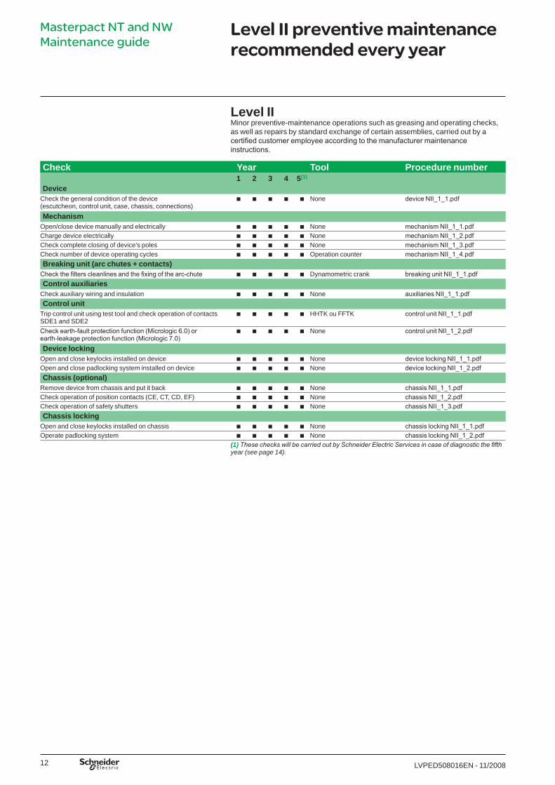
Level IIMinor preventive-maintenance operations such as greasing and operating checks, as well as repairs by standard exchange of certain assemblies, carried out by a certified customer employee according to the manufacturer maintenance instructions.
Check Year Tool Procedure number1 2 3 4 5(1)
DeviceCheck the general condition of the device (escutcheon, control unit, case, chassis, connections)
b b b b b None device NII_1_1.pdf
MechanismOpen/close device manually and electrically b b b b b None mechanism NII_1_1.pdfCharge device electrically b b b b b None mechanism NII_1_2.pdfCheck complete closing of device’s poles b b b b b None mechanism NII_1_3.pdfCheck number of device operating cycles b b b b b Operation counter mechanism NII_1_4.pdfBreaking unit (arc chutes + contacts)
Check the filters cleanlines and the fixing of the arc-chute b b b b b Dynamometric crank breaking unit NII_1_1.pdfControl auxiliaries
Check auxiliary wiring and insulation b b b b b None auxiliaries NII_1_1.pdfControl unit
Trip control unit using test tool and check operation of contacts SDE� and SDE2
b b b b b HHTK ou FFTK control unit NII_1_1.pdf
Check earth-fault protection function (Micrologic 6.0) or earth-leakage protection function (Micrologic 7.0)
b b b b b None control unit NII_1_2.pdf
Device lockingOpen and close keylocks installed on device b b b b b None device locking NII_1_1.pdfOpen and close padlocking system installed on device b b b b b None device locking NII_1_2.pdfChassis (optional)
Remove device from chassis and put it back b b b b b None chassis NII_1_1.pdfCheck operation of position contacts (CE, CT, CD, EF) b b b b b None chassis NII_1_2.pdfCheck operation of safety shutters b b b b b None chassis NII_1_3.pdfChassis locking
Open and close keylocks installed on chassis b b b b b None chassis locking NII_1_1.pdfOperate padlocking system b b b b b None chassis locking NII_1_2.pdf
(1) These checks will be carried out by Schneider Electric Services in case of diagnostic the fifth year (see page 14).
Masterpact NT and NW Maintenance guide
LVPED508016ENp1_p28.indd 12 25/11/2008 15:46:15

�3LVPED5080�6EN - ��/2008
Level III preventive maintenance recommended every 2 years
Level III General preventive-maintenance operations such as general adjustments, trouble-shooting and diagnosis of breakdowns, repairs by exchange of components or functional parts, minor mechanical repairs, carried out by a qualified customer technician using the tools and measurement/setting devices specified in the manufacturer maintenance instructions.
Check Year Tool Procedure number1 2 3 4 5(1)
MechanismCheck gear-motor charging time at 0,85 Un b b b Stop-watch + external
power supplymechanism NIII_2_1.pdf
Check general condition of mechanism b b b Screwdriver mechanism NIII_2_2.pdfBreaking unit (arc chutes + contacts)
Check condition of breaking unit b b b Screwdriver breaking unit NIII_2_1.pdfControl auxiliaries
Check operation of indication contacts(OF / PF / MCH)
b b b Wmetre auxiliaries NIII_2_1.pdf
Check closing operation of control auxiliaryXF at 0.85 Un
b b b External power supply auxiliaires NIII_2_2.pdf
Check opening operation of control auxiliaryMX at 0.70 Un
b b b External power supply auxiliaires NIII_2_3.pdf
Check operation of control auxiliary MN/MNR between 0.35 and 0.7 Un
b b b External power supply auxiliaries NIII_2_4.pdf
Check delay of MNR devices at 0.35 and 0.7 Un b b b External power supply auxiliaires NIII_2_5.pdfCheck MX tripping time b b b Tester auxiliaires NIII_2_6.pdfControl unit
Check tripping curves using test tool, signallling LED (tripped, overload)Save results on PC
b b b FFTKFFTK report generator software
control unit NIII_2_1.pdf
Chassis (optional) Dust and regrease chassis b b b Mobilith SHC�00 chassis NIII_2_1.pdfRegrease disconnecting-contact clusters(specific case of corrosive athmospheres)
b b b Mobilith SHC�00 chassis NIII_2_2.pdf
Power connectionsCheck and tighten loose connections Only after a visual
inspection showing overheating marks
Dynamometric crank power connections NIII_2_1.pdf
(1) These checks and tests will be carried out by Schneider Electric Services in case of diagnostic the fifth year (see page 14).
Masterpact NT and NW Maintenance guide
LVPED508016ENp1_p28.indd 13 25/11/2008 15:46:16
�4 LVPED5080�6EN - ��/2008
Level IV manufacturer diagnostic and replacement of components recommended every 5 years
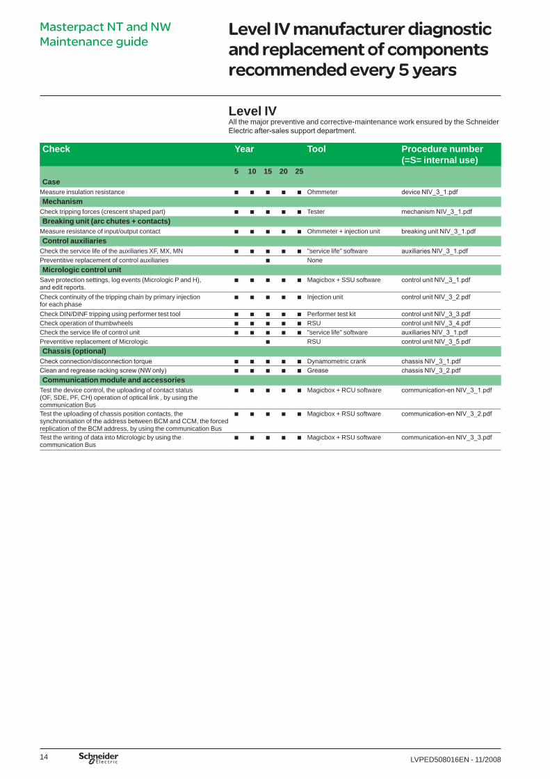
Level IV All the major preventive and corrective-maintenance work ensured by the Schneider Electric after-sales support department.
Check Year Tool Procedure number (=S= internal use)
5 10 15 20 25Case
Measure insulation resistance b b b b b Ohmmeter device NIV_3_1.pdfMechanism
Check tripping forces (crescent shaped part) b b b b b Tester mechanism NIV_3_1.pdfBreaking unit (arc chutes + contacts)
Measure resistance of input/output contact b b b b b Ohmmeter + injection unit breaking unit NIV_3_1.pdfControl auxiliaries
Check the service life of the auxiliaries XF, MX, MN b b b b b "service life" software auxiliaries NIV_3_1.pdfPreventitive replacement of control auxiliaries b NoneMicrologic control unit
Save protection settings, log events (Micrologic P and H), and edit reports.
b b b b b Magicbox + SSU software control unit NIV_3_1.pdf
Check continuity of the tripping chain by primary injection for each phase
b b b b b Injection unit control unit NIV_3_2.pdf
Check DIN/DINF tripping using performer test tool b b b b b Performer test kit control unit NIV_3_3.pdfCheck operation of thumbwheels b b b b b RSU control unit NIV_3_4.pdfCheck the service life of control unit b b b b b "service life" software auxiliaries NIV_3_1.pdfPreventitive replacement of Micrologic b RSU control unit NIV_3_5.pdfChassis (optional)
Check connection/disconnection torque b b b b b Dynamometric crank chassis NIV_3_1.pdfClean and regrease racking screw (NW only) b b b b b Grease chassis NIV_3_2.pdfCommunication module and accessories
Test the device control, the uploading of contact status (OF, SDE, PF, CH) operation of optical link , by using the communication Bus
b b b b b Magicbox + RCU software communication-en NIV_3_1.pdf
Test the uploading of chassis position contacts, the synchronisation of the address between BCM and CCM, the forced replication of the BCM address, by using the communication Bus
b b b b b Magicbox + RSU software communication-en NIV_3_2.pdf
Test the writing of data into Micrologic by using the communication Bus
b b b b b Magicbox + RSU software communication-en NIV_3_3.pdf
Masterpact NT and NW Maintenance guide
LVPED508016ENp1_p28.indd 14 25/11/2008 15:46:16
�5LVPED5080�6EN - ��/2008
Causes of accelerated ageing
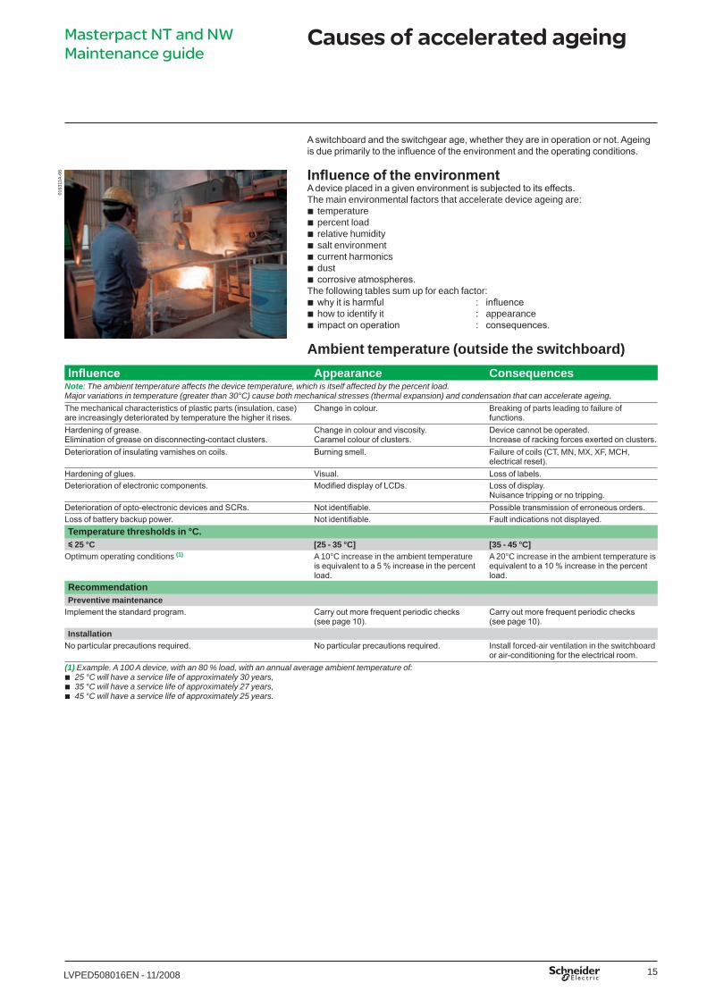
A switchboard and the switchgear age, whether they are in operation or not. Ageing is due primarily to the influence of the environment and the operating conditions.
Influence of the environmentA device placed in a given environment is subjected to its effects. The main environmental factors that accelerate device ageing are:
temperaturepercent loadrelative humiditysalt environmentcurrent harmonicsdustcorrosive atmospheres.
The following tables sum up for each factor: why it is harmful : influencehow to identify it : appearanceimpact on operation : consequences.
Ambient temperature (outside the switchboard)
bbbbbbb
bbb
Influence Appearance ConsequencesNote: The ambient temperature affects the device temperature, which is itself affected by the percent load.Major variations in temperature (greater than 30°C) cause both mechanical stresses (thermal expansion) and condensation that can accelerate ageing.The mechanical characteristics of plastic parts (insulation, case) are increasingly deteriorated by temperature the higher it rises.
Change in colour. Breaking of parts leading to failure of functions.
Hardening of grease.Elimination of grease on disconnecting-contact clusters.
Change in colour and viscosity.Caramel colour of clusters.
Device cannot be operated.Increase of racking forces exerted on clusters.
Deterioration of insulating varnishes on coils. Burning smell. Failure of coils (CT, MN, MX, XF, MCH, electrical reset).
Hardening of glues. Visual. Loss of labels.Deterioration of electronic components. Modified display of LCDs. Loss of display.
Nuisance tripping or no tripping.Deterioration of opto-electronic devices and SCRs. Not identifiable. Possible transmission of erroneous orders.Loss of battery backup power. Not identifiable. Fault indications not displayed.Temperature thresholds in °C.y 25 °C [25 - 35 °C] [35 - 45 °C]
Optimum operating conditions (1) A �0°C increase in the ambient temperature is equivalent to a 5 % increase in the percent load.
A 20°C increase in the ambient temperature is equivalent to a 10 % increase in the percent load.
RecommendationPreventive maintenance
Implement the standard program. Carry out more frequent periodic checks (see page 10).
Carry out more frequent periodic checks (see page 10).
InstallationNo particular precautions required. No particular precautions required. Install forced-air ventilation in the switchboard
or air-conditioning for the electrical room.(1) Example. A 100 A device, with an 80 % load, with an annual average ambient temperature of:
25 °C will have a service life of approximately 30 years, 35 °C will have a service life of approximately 27 years,45 °C will have a service life of approximately 25 years.
bbb
0�63
��A
-66
Masterpact NT and NW Maintenance guide
LVPED508016ENp1_p28.indd 15 25/11/2008 15:46:16
�6 LVPED5080�6EN - ��/2008
Causes of accelerated ageing
Percent load (I/In)Influence Appearance Consequences
Note: The percent load affects the device temperature, which is itself affected by the ambient temperature.Ageing of plastic insulation. Change in colour of insulation. Breaking of parts leading to failure of functions.Ageing of grease. Change in colour and viscosity. Increase in mechanical friction.Ageing of electronic components. Modified display of LCDs. A 10 °C increase (i.e. an 85 percent load) cuts the
service life of components by approximately half.Deterioration of characteristics:
steel springs (above �00°C),stainless steel springs (above 200°C).
bb
Rupture. Non operation of mechanisms.
Thresholdsy 80 %, 24/24 hours y 90 %, 8/24 hours y 90 %, 24/24 hours In, 8/24 hours In, 24/24 hours
Maximum percent load generally taken into account in sizing the installation. At this percent load, temperature rise is reduced approximately 40 % with respect to a �00 percent load.
At this percent load, temperature rise is reduced only 20 %. Heating and cooling cycles impact on the mechanical junctions of the power circuit.
The thermal stress for continuous operation is three times higher than in the previous case, but the absence of thermal cycles slows ageing of the electromechanical components.
Between 90 and �00 %, temperature rise is close to its maximum value. Heating and cooling cycles impact on the mechanical junctions of the power circuit, with major impact on ageing.
Between 90 and �00 %, temperature rise is close to its maximum value.This situation has a major impact on ageing. It is not recommended.
RecommendationPreventive maintenance
Implement the standard program.
Carry out more frequent periodic checks (see page 10).
Preventive maintenance is difficult due to the continuous process.
Carry out more frequent periodic checks (see page 10).Inspect for condensation.
Preventive maintenance is difficult due to the continuous process.Plan more frequent periodic checks.
InstallationNormal conditions. Provide ventilation for the
switchboard.Spread the load over other outgoers.Install a device with a higher rating.
DB
�090
68Masterpact NT and NW Maintenance guide
LVPED508016ENp1_p28.indd 16 25/11/2008 15:46:17

�7LVPED5080�6EN - ��/2008
Causes of accelerated ageing
Relative humidityInfluence Appearance Consequences
Corrosion of metal surfaces that is accelerated when a pollutant is present (corrosive gas, salt, chlorine, etc.).
Appearance of: red rust on iron,white rust on zinc,blue deposit on copper,black deposit on silver.
bbbb
Increase in friction.Risk of mechanical rupture resulting in non operation of mechanisms.Increase in contact resistance (clusters and main contacts).
Deterioration of dielectric qualities of plastics. White traces on case. Risk of a reduction in insulation. Deterioration of electronic components, in particular SMCs and silver-coated components. This phenomenon is worsened by the presence of H2S corrosive gas (hydrogen sulphide).
Not visible.Appearance of dentrites on electronic boards.
Short-circuiting of circuits resulting in non operation of control-unit protection, measurement, indication and communication functions.
Deterioration of electronic components, in particular non-varnished copper circuits.
Not visible.Erosion of copper tracks.Oxidation of metal connectors of components and metal cases.Oxidation of connectors of integrated-circuits mounted on supports.
Failure due to short-circuit or open circuit.Rupture of component connectors along case.Poor contact with integrated-circuit supports.
Degradation of opto-electronic components. Failure of data transmission.Thresholds in %y 70 % 70 to 85 % > 85 %
Level of relative humidity generally found in continental and temperate zones.The level is generally lower in switchboards due to the internal temperature rise. No significant deterioration is noted at this level.
Level of relative humidity generally found in zones close to water.Possible appearance of condensation on cold parts and accelerated rusting.
Level of relative humidity generally found in tropical zones and certain factories (e.g. paper mills).Increased risk of condensation and rust resulting in difficulties to disconnect devices, risk of non opening or non closing.
RecommendationPreventive maintenance
Preventive maintenance Carry out more frequent periodic checks (see page 10).Measurement of insulation is advised every 5 years.
Carry out more frequent periodic checks (see page 10).Inspect for rust on metal parts.Measurement of insulation is imperative every 2 years.
InstallationNo particular precautions required. Install heating resistors in the switchboard.
0463
56A
-66
Masterpact NT and NW Maintenance guide
LVPED508016ENp1_p28.indd 17 25/11/2008 15:46:17
�8 LVPED5080�6EN - ��/2008
Causes of accelerated ageing
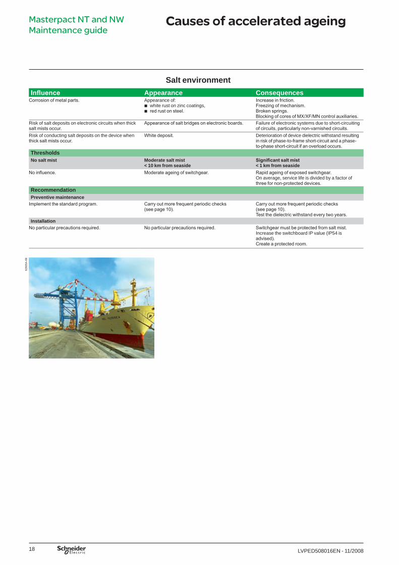
Salt environmentInfluence Appearance Consequences
Corrosion of metal parts. Appearance of:white rust on zinc coatings,red rust on steel.
bb
Increase in friction.Freezing of mechanism.Broken springs.Blocking of cores of MX/XF/MN control auxiliaries.
Risk of salt deposits on electronic circuits when thick salt mists occur.
Appearance of salt bridges on electronic boards. Failure of electronic systems due to short-circuiting of circuits, particularly non-varnished circuits.
Risk of conducting salt deposits on the device when thick salt mists occur.
White deposit. Deterioration of device dielectric withstand resulting in risk of phase-to-frame short-circuit and a phase-to-phase short-circuit if an overload occurs.
Thresholds No salt mist Moderate salt mist
< 10 km from seasideSignificant salt mist< 1 km from seaside
No influence. Moderate ageing of switchgear. Rapid ageing of exposed switchgear.On average, service life is divided by a factor of three for non-protected devices.
RecommendationPreventive maintenance
Implement the standard program. Carry out more frequent periodic checks (see page 10).
Carry out more frequent periodic checks (see page 10).Test the dielectric withstand every two years.
InstallationNo particular precautions required. No particular precautions required. Switchgear must be protected from salt mist.
Increase the switchboard IP value (IP54 is advised).Create a protected room.
6260
5A-6
6Masterpact NT and NW Maintenance guide
LVPED508016ENp1_p28.indd 18 25/11/2008 15:46:18
�9LVPED5080�6EN - ��/2008
Causes of accelerated ageing
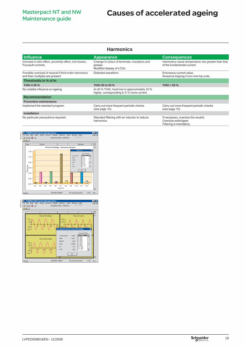
HarmonicsInfluence Appearance Consequences
Increase in skin effect, proximity effect, iron losses, Foucault currents.
Change in colour of terminals, insulators and grease.Modified display of LCDs.
Harmonics cause temperature rise greater than that of the fundamental current.
Possible overload of neutral if third-order harmonics and their multiples are present.
Distorted waveform. Erroneous current value.Nuisance tripping if non-rms trip units.
Thresholds in % of InTHDi y 30 % THDi 30 to 50 % THDi > 50 %
No notable influence on ageing. At 40 % THDI, heat loss is approximately �0 % higher, corresponding to 5 % more current.
RecommendationPreventive maintenance
Implement the standard program. Carry out more frequent periodic checks (see page 10).
Carry out more frequent periodic checks (see page 10).
InstallationNo particular precautions required. Standard filtering with an inductor to reduce
harmonics.If necessary, oversize the neutral.Oversize switchgear.Filtering is mandatory.
DB
�0�5
2�D
B�0
�522
Masterpact NT and NW Maintenance guide
LVPED508016ENp1_p28.indd 19 25/11/2008 15:46:19

20 LVPED5080�6EN - ��/2008
Causes of accelerated ageing
DustInfluence Appearance Consequences
Deposit on grease of mechanisms (device and chassis).
Change in colour and texture of greases. Premature wear of mechanisms because dust mixed with grease can be abrasive. Increase in mechanical friction and freezing of moving parts.Risk of device not moving on chassis.Risk of device non opening or non closing.
Deposit on grease of clusters. Change in colour and texture of greases. Increase in racking forces exerted.Increased contact resistance and temperature rise.
Deposit on displays. Screen data not legible.Deposit on insulation. Reduced insulation resistance (depends on type
of dust). This phenomenon is worsened by the presence of humidity.
Deposit on device contacts. Increased contact resistance and temperature rise.Deposit on opto-electronic communication system between devices.
Failure of communication-data transmission.
Dust depositLow level Moderate High
Quantity of dust generally deposited on and around devices in commercial buildings and on standard industrial premises.
Quantity of dust found in protected switchboards installed in dusty environments such as cement works, grain mills, incineration installations, plastic and steel mills, mines, etc.
Quantity of dust deposited on and around devices inside non-protected switchboards installed in dusty environments such as cement works, grain mills, incineration installations, plastic and steel mills, mines, etc.
RecommendationPreventive maintenance
Implement the standard program.It is advised to vacuum cleaner dust deposits.
Carry out more frequent periodic cleaning (see table 10).
Carry out more frequent periodic cleaning (see table 10).
InstallationSwitchboard with standard IP. Make sure the switchboard remains closed. Special equipment required to protect the
switchgear is mandatory.
0274
88A
-66
Masterpact NT and NW Maintenance guide
LVPED508016ENp1_p28.indd 20 25/11/2008 15:46:19

2�LVPED5080�6EN - ��/2008
Causes of accelerated ageing
Corrosive atmosphereCorrosive atmosphere
Influence Appearance Consequences Thresholds (ppm (1) in volume) Average value
SO2Sulphur dioxide
Corrosion of silver, aluminium and bare copper. Phenomenon accelerated by high temperature and relative humidity.
Blackening of exposed silver surfaces.Appearance of dendrites on electronic and power circuits.
Increased resistance of disconnecting contacts exposed to air.Excessive device temperature rise.Short-circuiting of circuits resulting in non operation of the control unit.
3C1: 0.0373C2: 0.113C3: 1.853C4: 4.8
H2SHydrogen sulphide
Sulphuration of silver, this phenomenon is accelerated by high temperatures.
Major blackening of exposed silver surfaces.Appearance of dendrites on electronic and power circuits.
Increased resistance of disconnecting contacts exposed to air.Excessive device temperature rise.Short-circuiting of circuits resulting in non operation of the control unit.
3C1: 0.00713C2: 0.0713C3: 2.13C4: 9.9
Cl2Chlorine
Corrosion of metal parts. Oxidation.Inter-granular corrosion of stainless steel.
Increase in friction.Risk of mechanical rupture.Breaking of stainless-steel springs.
3C1: 0.0343C2: 0.0343C3: 0.13C4: 0.2
NH3 Ammoniac
Attacks polycarbonates, corrodes copper.
Cracking of polycarbonates.Blackening of copper.
Risk of rupture.Increased temperature rise.
3C1: 0.423C2: 1.43C3: �43C4: 49
NO2Nitrogen oxide
Corrosion of metal parts. Oxidation. Increased temperature rise. 3C1: 0.0523C2: 0.263C3: 1.563C4: 5.2
Oily atmospheres Attacks polycarbonates. Cracking of polycarbonates. Risk of rupture.Increased temperature rise.
Environment categories as per standard 721-3-3Class3C1 3C2 3C3 3C4
Rural zones or urban zones with low industrial activity.
Urban zones with scattered industrial activity and heavy traffic.
Immediate vicinity of industrial pollution.Example, paper mills, water treatment, chemicals, synthetic fibres, smelting plants.
Inside polluting industrial premises.Example: paper mills, water treatment, chemicals, synthetic fibres, smelting plants.
Presence of corrosive gasesNegligible Low level Significant level High levelImpact on switchgear
No impact on service life because concentrations are very low.
Moderate impact on service life. Major impact, particularly concerning temperature rise.For electronic systems, no impact on varnished boards and gold-plated contacts.
Significantly reduced service life if no particular precautions are taken.For electronic systems, no impact on varnished boards and gold-plated contacts.
RecommendationPreventive maintenance
Implement the standard program. Implement the standard program."PYRATEX" grease can be used for the disconnecting contacts, but must be changed annually (see the manufacturer procedure).
Carry out more frequent periodic checks (see page 10).Change the grease on the disconnecting contacts.
Carry out more frequent periodic checks (see page 10).Change the grease on the disconnecting contacts.
InstallationNo particular precautions required. No particular precautions required. Use fixed rather than drawout
devices.It is advised to install the switchgear in a room protected from the pollution.Use fixed rather than drawout devices, or implement special solutions (gold-plated disconnecting contacts).
(1) ppm = Parts Per Million.
Masterpact NT and NW Maintenance guide
LVPED508016ENp1_p28.indd 21 25/11/2008 15:46:20
22 LVPED5080�6EN - ��/2008
Causes of accelerated ageing
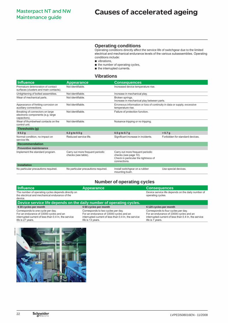
Operating conditionsOperating conditions directly affect the service life of switchgear due to the limited electrical and mechanical endurance levels of the various subassemblies. Operating conditions include:
vibrations,the number of operating cycles,the interrupted currents.
Vibrations
bbb
Influence Appearance ConsequencesPremature deterioration of contact surfaces (clusters and main contacts).
Not identifiable. Increased device temperature rise.
Untightening of bolted assemblies. Not identifiable. Increase in mechanical play.Wear of mechanical parts. Not identifiable. Broken springs.
Increase in mechanical play between parts.Appearance of fretting corrosion on auxiliary connections.
Not identifiable. Erroneous information or loss of continuity in data or supply, excessive temperature rise.
Breaking of connectors on large electronic components (e.g. large capacitors).
Not identifiable. Failure of protection function.
Wear of thumbwheel contacts on the control unit.
Not identifiable. Nuisance tripping or no tripping.
Thresholds (g)y 0.2 g 0.2 g to 0.5 g 0.5 g to 0.7 g > 0.7 g
Normal condition, no impact on service life.
Reduced service life. Significant increase in incidents. Forbidden for standard devices.
Recommendation Preventive maintenance
Implement the standard program. Carry out more frequent periodic checks (see table).
Carry out more frequent periodic checks (see page 10).Check in particular the tightness of connections.
InstallationNo particular precautions required. No particular precautions required. Install switchgear on a rubber
mounting bush.Use special devices.
Number of operating cyclesInfluence Appearance Consequences
The number of operating cycles depends directly on the electrical and mechanical endurance of the device.
Device service life depends on the daily number of operating cycles.
Device service life depends on the daily number of operating cycles.y 30 cycles per month y 60 cycles per month y 120 cycles per month
Corresponds to one cycle per day.For an endurance of �0000 cycles and an interrupted current of less than 0.4 In, the service life is 27 years.
Corresponds to two cycles per day.For an endurance of �0000 cycles and an interrupted current of less than 0.4 In, the service life is 13 years.
Corresponds to four cycles per day.For an endurance of �0000 cycles and an interrupted current of less than 0.4 In, the service life is 7 years.
6339
8A-6
4Masterpact NT and NW Maintenance guide
LVPED508016ENp1_p28.indd 22 25/11/2008 15:46:20
23LVPED5080�6EN - ��/2008
Causes of accelerated ageing
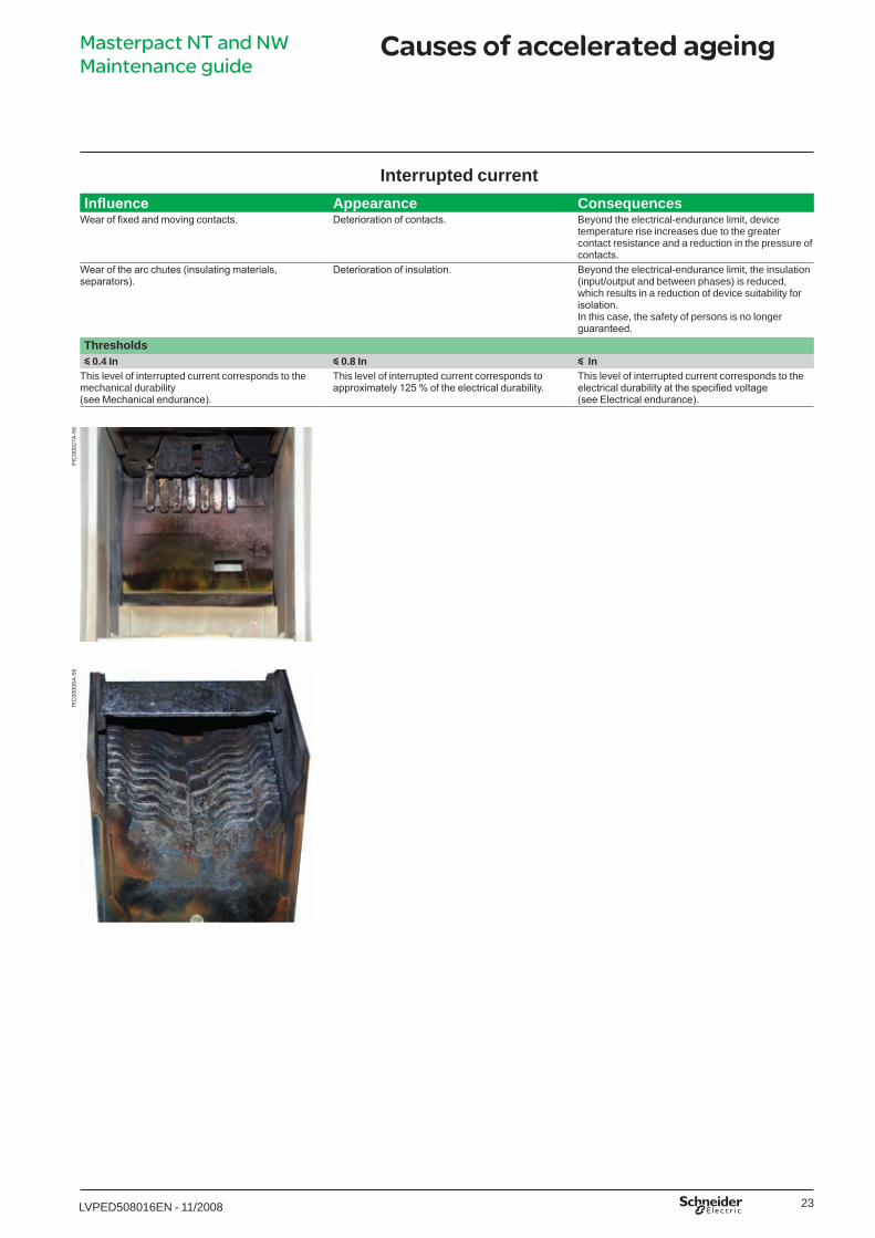
Interrupted currentInfluence Appearance Consequences
Wear of fixed and moving contacts. Deterioration of contacts. Beyond the electrical-endurance limit, device temperature rise increases due to the greater contact resistance and a reduction in the pressure of contacts.
Wear of the arc chutes (insulating materials, separators).
Deterioration of insulation. Beyond the electrical-endurance limit, the insulation (input/output and between phases) is reduced, which results in a reduction of device suitability for isolation.In this case, the safety of persons is no longer guaranteed.
Thresholdsy 0.4 In y 0.8 In y In
This level of interrupted current corresponds to the mechanical durability(see Mechanical endurance).
This level of interrupted current corresponds to approximately 125 % of the electrical durability.
This level of interrupted current corresponds to the electrical durability at the specified voltage(see Electrical endurance).
PIC
0002
7A-5
6P
IC00
005A
-56
Masterpact NT and NW Maintenance guide
LVPED508016ENp1_p28.indd 23 25/11/2008 15:46:21
24 LVPED5080�6EN - ��/2008
Operating limits
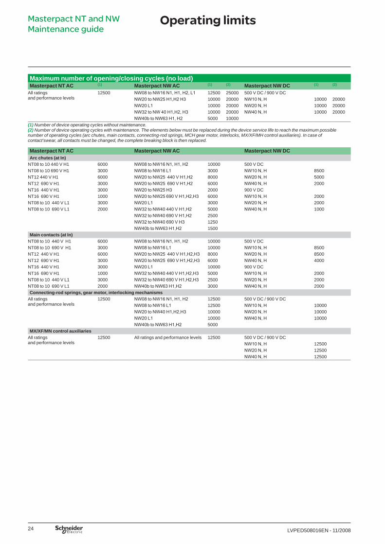
Maximum number of opening/closing cycles (no load)Masterpact NT AC (1) Masterpact NW AC (1) (2) Masterpact NW DC (1) (2)
All ratingsand performance levels
�2500 NW08 to NW16 N1, H1, H2, L1 �2500 25000 500 V DC / 900 V DCNW20 to NW25 H1,H2 H3 �0000 20000 NW10 N, H �0000 20000NW20 L1 �0000 20000 NW20 N, H �0000 20000NW32 to NW 40 H1,H2, H3 �0000 20000 NW40 N, H �0000 20000NW40b to NW63 H1, H2 5000 �0000
(1) Number of device operating cycles without maintenance.(2) Number of device operating cycles with maintenance. The elements below must be replaced during the device service life to reach the maximum possible number of operating cycles (arc chutes, main contacts, connecting-rod springs, MCH gear motor, interlocks, MX/XF/MH control auxiliaries). In case of contact’swear, all contacts must be changed, the complete breaking block is then replaced.
Masterpact NT AC Masterpact NW AC Masterpact NW DCArc chutes (at In)
NT08 to �0 440 V H� 6000 NW08 to NW16 N1, H1, H2 �0000 500 V DCNT08 to �0 690 V H� 3000 NW08 to NW16 L1 3000 NW10 N, H 8500NT�2 440 V H� 6000 NW20 to NW25 440 V H1,H2 8000 NW20 N, H 5000NT�2 690 V H� 3000 NW20 to NW25 690 V H1,H2 6000 NW40 N, H 2000NT�6 440 V H� 3000 NW20 to NW25 H3 2000 900 V DCNT�6 690 V H� �000 NW20 to NW25 690 V H1,H2,H3 6000 NW10 N, H 2000NT08 to �0 440 V L� 3000 NW20 L1 3000 NW20 N, H 2000NT08 to �0 690 V L� 2000 NW32 to NW40 440 V H1,H2 5000 NW40 N, H �000
NW32 to NW40 690 V H1,H2 2500NW32 to NW40 690 V H3 �250NW40b to NW63 H1,H2 �500
Main contacts (at In)NT08 to �0 440 V H� 6000 NW08 to NW16 N1, H1, H2 �0000 500 V DCNT08 to �0 690 V H� 3000 NW08 to NW16 L1 �0000 NW10 N, H 8500NT�2 440 V H� 6000 NW20 to NW25 440 V H1,H2,H3 8000 NW20 N, H 8500NT�2 690 V H� 3000 NW20 to NW25 690 V H1,H2,H3 6000 NW40 N, H 4000NT�6 440 V H� 3000 NW20 L1 �0000 900 V DCNT�6 690 V H� �000 NW32 to NW40 440 V H1,H2,H3 5000 NW10 N, H 2000NT08 to �0 440 V L� 3000 NW32 to NW40 690 V H1,H2,H3 2500 NW20 N, H 2000NT08 to �0 690 V L� 2000 NW40b to NW63 H1,H2 3000 NW40 N, H 2000Connecting-rod springs, gear motor, interlocking mechanisms
All ratingsand performance levels
�2500 NW08 to NW16 N1, H1, H2 �2500 500 V DC / 900 V DCNW08 to NW16 L1 �2500 NW10 N, H �0000NW20 to NW40 H1,H2,H3 �0000 NW20 N, H �0000NW20 L1 �0000 NW40 N, H �0000NW40b to NW63 H1,H2 5000
MX/XF/MN control auxiliariesAll ratingsand performance levels
�2500 All ratings and performance levels �2500 500 V DC / 900 V DCNW10 N, H �2500NW20 N, H �2500NW40 N, H �2500
Masterpact NT and NW Maintenance guide
LVPED508016ENp1_p28.indd 24 25/11/2008 15:46:21
25LVPED5080�6EN - ��/2008
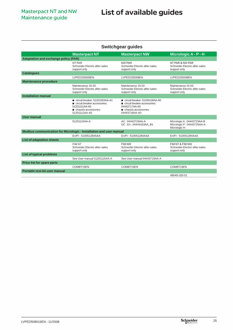
List of available guides
Switchgear guidesMasterpact NT Masterpact NW Micrologic A - P - H
Adaptation and exchange policy (PAR)NT PARSchneider Electric after-sales support only
NW PARSchneider Electric after-sales support only
NT PAR & NW PARSchneider Electric after-sales support only
Catalogues LVPED205008EN LVPED205008EN LVPED205008EN
Maintenance procedureMaintenance �5-03Schneider Electric after-sales support only
Maintenance �5-03Schneider Electric after-sales support only
Maintenance �5-03Schneider Electric after-sales support only
Installation manualcircuit breaker: 5�20�003AA-A�circuit breaker accessories:
5�20����AA-A0chassis accessories:
5�20���2AA-A0
bb
b
circuit breaker: 5��56��8AA-A0circuit breaker accessories:
044437�7AA-A0chassis accessories:
044437�8AA-A0
bb
b
User manual5�20���5AA-A AC : 044437�9AA-A
DC : En : 04444�63AA_B�Micrologic A : 04443723AA-BMicrologic P : 04443725AA-AMicrologic H :
Modbus communication for Micrologic - Installation and user manual En/Fr : 5�005�284AAA En/Fr : 5�005�284AAA En/Fr : 5�005�284AAA
List of adaptation sheetsFIM NTSchneider Electric after-sales support only
FIM NWSchneider Electric after-sales support only
FIM NT & FIM NWSchneider Electric after-sales support only
List of typical problems See User manual 5�20���5AA-A See User manual 044437�9AA-A
Price list for spare partsCOMBT�5EN COMBT�5EN COMBT�5EN
Portable test-kit user manual48049-�83-0�
Masterpact NT and NW Maintenance guide
LVPED508016ENp1_p28.indd 25 25/11/2008 15:46:21
26 LVPED5080�6EN - ��/2008
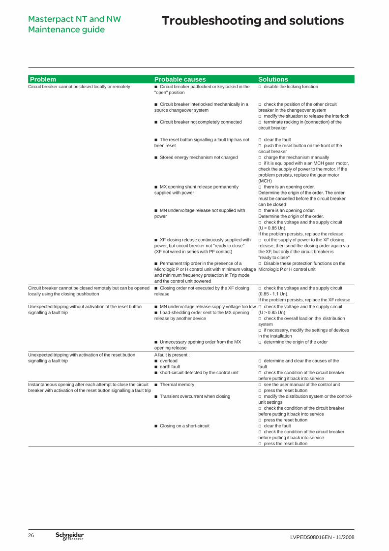
Troubleshooting and solutionsMasterpact NT and NW Maintenance guide
Problem Probable causes SolutionsCircuit breaker cannot be closed locally or remotely Circuit breaker padlocked or keylocked in the
"open" position
Circuit breaker interlocked mechanically in a source changeover system
Circuit breaker not completely connected
The reset button signalling a fault trip has not been reset
Stored energy mechanism not charged
MX opening shunt release permanently supplied with power
MN undervoltage release not supplied with power
XF closing release continuously supplied with power, but circuit breaker not "ready to close" (XF not wired in series with PF contact)
Permanent trip order in the presence of a Micrologic P or H control unit with minimum voltage and minimum frequency protection in Trip mode and the control unit powered
b
b
b
b
b
b
b
b
b
disable the locking fonction
check the position of the other circuit breaker in the changeover system
modify the situation to release the interlockterminate racking in (connection) of the
circuit breaker
clear the faultpush the reset button on the front of the
circuit breakercharge the mechanism manuallyif it is equipped with a an MCH gear motor,
check the supply of power to the motor. If the problem persists, replace the gear motor (MCH)
there is an opening order. Determine the origin of the order. The order must be cancelled before the circuit breaker can be closed
there is an opening order. Determine the origin of the order.
check the voltage and the supply circuit (U > 0.85 Un). If the problem persists, replace the release
cut the supply of power to the XF closing release, then send the closing order again via the XF, but only if the circuit breaker is "ready to close"
Disable these protection functions on the Micrologic P or H control unit
v
v
vv
vv
vv
v
v
v
v
v
Circuit breaker cannot be closed remotely but can be opened locally using the closing pushbutton
Closing order not executed by the XF closing releaseb check the voltage and the supply circuit
(0.85 - 1.1 Un). If the problem persists, replace the XF release
v
Unexpected tripping without activation of the reset button signalling a fault trip
MN undervoltage release supply voltage too lowLoad-shedding order sent to the MX opening
release by another device
Unnecessary opening order from the MX opening release
bb
b
check the voltage and the supply circuit (U > 0.85 Un)
check the overall load on the distribution system
if necessary, modify the settings of devices in the installation
determine the origin of the order
v
v
v
v
Unexpected tripping with activation of the reset button signalling a fault trip
A fault is present :overloadearth faultshort-circuit detected by the control unit
bbb
determine and clear the causes of the fault
check the condition of the circuit breaker before putting it back into service
v
v
Instantaneous opening after each attempt to close the circuit breaker with activation of the reset button signalling a fault trip
Thermal memory
Transient overcurrent when closing
Closing on a short-circuit
b
b
b
see the user manual of the control unitpress the reset button modify the distribution system or the control-
unit settingscheck the condition of the circuit breaker
before putting it back into service press the reset buttonclear the faultcheck the condition of the circuit breaker
before putting it back into service press the reset button
vvv
v
vvv
v
LVPED508016ENp1_p28.indd 26 25/11/2008 15:46:22

27LVPED5080�6EN - ��/2008
Troubleshooting and solutionsMasterpact NT and NW Maintenance guide
Problem Probable causes SolutionsCircuit breaker cannot be opened remotely, but can be opened locally
Opening order not executed by the MX opening release
Opening order not executed by the MN undervoltage release
b
b
check the voltage and the supply circuit (0.7 - 1.1 Un). If the problem persists, replace the MX release
drop in voltage insufficient or residual voltage (> 0.35 Un) across the terminals of the undervoltage release. If the problem persists, replace the MN release
v
v
Circuit breaker cannot be opened locally Operating mechanism malfunction or welded contactsb contact a Schneider Electric service
centrev
Circuit breaker cannot be reset locally but not remotely Insufficient supply voltage for the MCH gear motorb check the voltage and the supply circuit
(0.7 - 1.1 Un). If the problem persists, replace the MCH release
v
Nuisance tripping of the circuit breaker with activation of the reset button signalling a fault trip
Reset button not pushed-in completelyb push the reset button in completelyv
Impossible to insert the crank in connected, test or disconnected position
A padlock or keylock is present on the chassis or a door interlock is presentb disable the locking functionv
Impossible to turn the crank The reset button has not been pressedb press the reset button vCircuit breaker cannot be removed from chassis Circuit breaker not in disconnected position
The rails are not completely out
b
b
turn the crank until the circuit breaker is in disconnected position and the reset button out
pull the rails all the way out
v
vCircuit breaker cannot be connected (racked in) Cradle/circuit breaker mismatch protection
The safety shutters are lockedThe disconnecting-contact clusters are
incorrectly positionedCradle locked in disconnected positionThe reset button has not been pressed,
preventing rotation of the crankThe circuit breaker has not been sufficiently
inserted in the cradle
b
bb
bb
b
check that the cradle corresponds with the circuit breaker
remove the lock(s)reposition the clusters
disable the cradle locking functionpress the reset button
insert the circuit breaker completely so that it is engaged in the racking mechanism
v
vv
vv
v
Circuit breaker cannot be locked in disconnected position The circuit breaker is not in the right position
The cranck is still in the cradle
b
b
check the circuit breaker position by making sure the reset button is out
remove the crank and store it
v
v
Circuit breaker cannot be locked in connected, test or disconnected position
Check that locking in any position is enabledThe circuit breaker is not in the right position
The cranck is still in the cradle
bb
b
contact a Schneider service centrecheck the circuit breaker position by
making sure the reset button is outremove the crank and store it
vv
vThe crank cannot be inserted to connect or disconnected the circuit breaker
The rails are not completely inb push the rails all the way inv
The right-hand rail (chassis alone) or the circuit breaker cannot be drawn out
The crank is still in the chassisb remove the crank and store itv
LVPED508016ENp1_p28.indd 27 25/11/2008 15:46:22

28 LVPED5080�6EN - ��/2008
Notes
LVPED508016ENp1_p28.indd 28 25/11/2008 15:46:22

LVPED508016EN_couv.indd 3 25/11/2008 15:45:01

11-2008LVPED508016EN
Schneider Electric Industries SAS35 rue Joseph Monier92500 Rueil-Malmaison France
http://www.schneider-electric.com
As standards, specifications and designs change from time to time, please ask for confirmation of the information given in this publication.
This document has been printed on ecological paper
Design: Schneider ElectricPhotos: Schneider ElectricPrinted: Ingoprint - Made in Spain A
RT9
6031
2 ©
200
8 - S
chne
ider
Ele
ctric
- A
ll rig
hts
rese
rved
.
LVPED508016EN_couv.indd 4 25/11/2008 15:45:02