low voltage high bandwidth quad dpdt switch
TRANSCRIPT

This is information on a product in full production.
August 2013 DocID15992 Rev 4 1/20
STG3820
Low voltage high bandwidth quad DPDT switch
Datasheet - production data
Features
Ultralow power dissipation
– ICC = 1 µA (max.) at TA = 85 °C
Low “ON” resistance
– RON = 5.4 (TA = 25 °C) at VCC = 4.3 V
– RON = 6.6 (TA = 25 °C) at VCC = 3.0 V
Wide operating voltage range
– VCC (OPR.) = 1.65 V to 4.3 V
4.3 V tolerant and 1.8 V compatible threshold on digital control input at VCC = 2.3 V to 3.0 V
4 select pins controlling 2 switches each
Typical bandwidth (-3 dB) at 800 MHz on all channels
USB (2.0) high speed (480 Mbps) signal switching compliant
Integrated fail safe function
Latch-up performance exceeds 100 mA per JESD 78, Class II
ESD performance exceeds JESD22 2000-V human body model (A114-A)
Applications
Mobile phones
Description
The STG3820 device is a high-speed CMOS low voltage quad analog DPDT (dual pole dual throw) switch or 2:1 multiplexer/demultiplexer switch fabricated in silicon gate C2MOS technology. It is designed to operate from 1.65 V to 4.3 V, making this device ideal for portable applications.
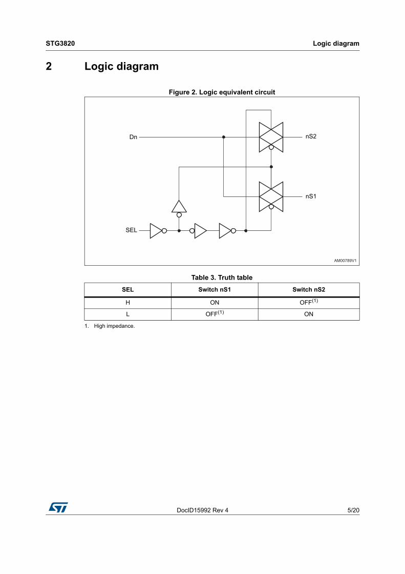
The SELm-n input is provided to control the switches. The switches nS1 and mS1 are ON (connected to common ports Dn and Dm respectively) when the SELm-n input is held high and OFF (high impedance state exists between the two ports) when the SELm-n is held low. The switches nS2 and mS2 are ON (connected to common port Dn and Dm respectively) when the SELm-n input is held low and OFF (high impedance state exists between the two ports) when the SELm-n is held high.
The STG3820 device has an integrated fail safe function to withstand overvoltage condition when the device is powered off. Additional key features are fast switching speed, break-before-make-delay time and ultralow power consumption. All inputs and outputs are equipped with protection circuits against static discharge, giving them ESD immunity and transient excess voltage.
Table 1. Device summary
Flip Chip 30
(2.0 x 2.4 mm)
Order code Package Packing
STG3820BJRFlip Chip 30
(2.0 x 2.4 mm)Tape and reel
www.st.com

Contents STG3820
2/20 DocID15992 Rev 4
Contents
1 Pin settings . . . . . . . . . . . . . . . . . . . . . . . . . . . . . . . . . . . . . . . . . . . . . . . . 3
1.1 Pin connection . . . . . . . . . . . . . . . . . . . . . . . . . . . . . . . . . . . . . . . . . . . . . . 3
1.2 Pin description . . . . . . . . . . . . . . . . . . . . . . . . . . . . . . . . . . . . . . . . . . . . . . 3
2 Logic diagram . . . . . . . . . . . . . . . . . . . . . . . . . . . . . . . . . . . . . . . . . . . . . . 5
3 Maximum ratings . . . . . . . . . . . . . . . . . . . . . . . . . . . . . . . . . . . . . . . . . . . . 6
Recommended operating conditions . . . . . . . . . . . . . . . . . . . . . . . . . . . . . . . . . . . 6
4 Electrical characteristics . . . . . . . . . . . . . . . . . . . . . . . . . . . . . . . . . . . . . 7
5 Test circuits . . . . . . . . . . . . . . . . . . . . . . . . . . . . . . . . . . . . . . . . . . . . . . . 12
6 Package information . . . . . . . . . . . . . . . . . . . . . . . . . . . . . . . . . . . . . . . . 16
7 Revision history . . . . . . . . . . . . . . . . . . . . . . . . . . . . . . . . . . . . . . . . . . . 19

DocID15992 Rev 4 3/20
STG3820 Pin settings
20
1 Pin settings
1.1 Pin connection
Figure 1. Pin connection
1.2 Pin description
Table 2. Pin assignment
Pin number Symbol Name and function
A1 1S1 Independent channel for switch 1
A2 D1 Common channel for switch 1
A3 1S2 Independent channel for switch 1
A4 5S2 Independent channel for switch 5
A5 D5 Common channel for switch 5
A6 5S1 Independent channel for switch 5
B1 2S1 Independent channel for switch 2
B2 D2 Common channel for switch 2
B3 2S2 Independent channel for switch 2
B4 6S2 Independent channel for switch 6
B5 D6 Common channel for switch 6
B6 6S1 Independent channel for switch 6

Pin settings STG3820
4/20 DocID15992 Rev 4
Pin number Symbol Name and function
C1 SEL1-2 Switch 1-2 selection control
C2 VCC Positive supply voltage
C3 SEL3-4 Switch 3-4 selection control
C4 SEL5-6 Switch 5-6 selection control
C5 GND Ground (0 V)
C6 SEL7-8 Switch 7-8 selection control
D1 3S1 Independent channel for switch 3
D2 D3 Common channel for switch 3
D3 3S2 Independent channel for switch 3
D4 7S2 Independent channel for switch 7
D5 D7 Common channel for switch 7
D6 7S1 Independent channel for switch 7
E1 4S1 Independent channel for switch 4
E2 D4 Common channel for switch 4
E3 4S2 Independent channel for switch 4
E4 8S2 Independent channel for switch 8
E5 D8 Common channel for switch 8
E6 8S1 Independent channel for switch 8
Table 2. Pin assignment (continued)
DocID15992 Rev 4 5/20
STG3820 Logic diagram
20
2 Logic diagram
Figure 2. Logic equivalent circuit
Table 3. Truth table
SEL Switch nS1 Switch nS2
H ON OFF(1)
L OFF(1)
1. High impedance.
ON
Dn
SEL
nS2
nS1
AM00789V1

Maximum ratings STG3820
6/20 DocID15992 Rev 4
3 Maximum ratings
Stressing the device above the rating listed in Table 4: Absolute maximum ratings may cause permanent damage to the device. These are stress ratings only and operation of the device at these or any other conditions above those indicated in Table 5: Recommended operating conditions of this specification is not implied. Exposure to absolute maximum ratings conditions for extended periods may affect device reliability.
Recommended operating conditions
Table 4. Absolute maximum ratings
Symbol Parameter Value Unit
VCC Supply voltage -0.5 to 6.0 V
VI DC input voltage -0.5 to VCC + 0.5 V
VIC DC control input voltage -0.5 to 5.5 V
VO DC output voltage -0.5 to VCC + 0.5 V
IIKC DC input diode current on control pin (VSEL < 0 V) -50 mA
IIK DC input diode current (VSEL < 0 V) ±50 mA
IOK DC output diode current ±20 mA
IO DC output current ±128 mA
IOP DC output current peak (pulse at 1 ms, 10% duty cycle) ±300 mA
ICC or IGND DC VCC or ground current ±100 mA
PD Power dissipation at TA = 70 °C 1120 mW
Tstg Storage temperature -65 to +150 °C
TL Lead temperature (10 sec.) 300 °C
Table 5. Recommended operating conditions
Symbol Parameter Value Unit
VCC Supply voltage 1.65 to 4.3 V
VI Input voltage 0 to VCC V
VIC Control input voltage 0 to 4.3 V
VO Output voltage 0 to VCC V
Top Operating temperature -40 to 85 °C
dt/dvInput rise and fall time control input
VL = 1.65 V to 2.7 V 0 to 20ns/V
VL = 3.0 V to 4.3 V 0 to 10

DocID15992 Rev 4 7/20
STG3820 Electrical characteristics
20
4 Electrical characteristics
Table 6. DC specifications
Symbol Parameter VCC (V)Test
conditions
Value
UnitTA = 25 °C -40 to 85 °C
Min. Typ. Max. Min. Max.
VIHHigh level input voltage
1.65 – 1.950.65
VCC
0.65
VCC
V
2.3 – 2.5 1.2 1.2
2.7 – 3.0 1.3 1.3
3.3 – 3.6 1.4 1.4
4.3 1.6 1.6
VILLow level input voltage
1.65 – 1.95 0.25 0.25
V
2.3 – 2.5 0.25 0.25
2.7 – 3.0 0.25 0.25
3.3 – 3.6 0.30 0.30
4.3 0.40 0.40
RPEAKSwitch ON peak resistance
1.8
VS = 0 V to VCC IS = 8 mA
17.0 19.6
Ω
2.7 7.5 8.7
3.0 6.6 7.6
3.7 5.8 6.7
4.3 5.4 6.2
RONSwitch ON resistance
3.0VS = 3 V
IS = 8 mA 5.1 5.8
Ω
3.0VS = 0.4 V
IS = 8 mA 6.3 7.3
RON
ON resistance match between channels(1)
1.8
VS at RON MAX IS = 8 mA
Ω
2.7
3.0 0.3
3.7
4.3

Electrical characteristics STG3820
8/20 DocID15992 Rev 4
RFLATON resistance flatness(2)
1.8VS = 0 V to
0.4 V
IS = 8 mA 4.5
Ω
1.8
VS = 0 V to VCC
IS = 8 mA
9.5
2.7 2.2
3.0 1.8
3.7 1.6
4.3 1.6
IOFF
OFF state leakage current (Sn), (D)
4.3 VS = 0.3 or 4 V -20 20 -100 100 nA
IINInput leakage current
0 to 4.3VSEL = 0 to
4.3 V-0.2 0.2 -1.0 1.0 µA
ICCQuiescent supply current
1.65 to 4.3VSEL = VCC or
GND-0.2 0.2 -1.0 1.0 µA
ICCLV
Quiescent supply current for low voltage driving(3)
4.3
VSEL = 1.65 V ±37 ±50 ±100
µAVSEL = 1.80 V ±33 ±40 ±50
VSEL = 2.60 V ±11 ±20 ±30
1. RON = max. |mSN - nSN|, where m = 1 to 8 and n = 1 to 8, N = 1, 2.
2. Flatness is defined as the difference between the maximum and minimum value of on-resistance as measured over the specified analog signal ranges.
3. Measurement is for one SEL pin.
Table 6. DC specifications (continued)
Symbol Parameter VCC (V)Test
conditions
Value
UnitTA = 25 °C -40 to 85 °C
Min. Typ. Max. Min. Max.

DocID15992 Rev 4 9/20
STG3820 Electrical characteristics
20
Table 7. AC electrical characteristics (CL = 35 pF, RL = 50 Ω, tr = tf 5 ns)
Symbol Parameter VCC (V)Test
conditions
Value
UnitTA = 25 °C -40 to 85 °C
Min. Typ. Max. Min. Max.
tPLH, tPHLPropagation delay
1.65 - 1.95 0.21
ns2.3 - 2.7 0.15
3.0 - 3.3 0.14
3.6 - 4.3 0.13
tON Turn-on time
1.65 - 1.95 VS = 0.8 V 36
ns2.3 - 2.7
VS = 1.5 V
20 23 26
3.0 - 3.3 15 17 20
3.6 - 4.3 13 15 17
tOFF Turn-off time
1.65 - 1.95 VS = 0.8 V 29
ns2.3 - 2.7
VS = 1.5 V
19 22 25
3.0 - 3.3 14 16 18
3.6 - 4.3 11 13 14
tDBreak-before-make time delay
1.65 - 1.95
CL = 35 pF
RL = 50 Ω
VS = 1.5 V
10
ns2.3 - 2.7 7
3.0 - 3.3 6
3.6 - 4.3 4
Q Charge injection
1.65
CL = 100 pF
VGEN = 0 V
RGEN = 0 Ω
3.9
pC2.3 4.8
3.0 5.2
4.3 6.4

Electrical characteristics STG3820
10/20 DocID15992 Rev 4
Table 8. AC electrical characteristics (CL = 5 pF, RL = 50 Ω, TA = 25 °C)
Symbol Parameter VCC (V) Test conditions
Value
UnitTA = 25 °C -40 to 85 °C
Min. Typ. Max. Min. Max.
OIRR OFF isolation(1) 1.65 – 4.3
VS = 1 VRMS,
f = 1 MHz
signal = 0 dBm
-78
dBVS = 1 VRMS,
f = 10 MHz
signal = 0 dBm
-57
Xtalk Crosstalk 1.65 – 4.3
VS = 1 VRMS,
f = 1 MHz
signal = 0 dBm
-78
dBVS = 1 VRMS,
f = 10 MHz
signal = 0 dBm
-58
BW -3dB bandwidth 3.0 – 4.3RL = 50 Ω
signal = 0 dBm 800 MHz
CINControl pin input capacitance
VCC = 0 V 2 pF
CSn Sn port capacitance 3.3
F = 240 MHz,
switch is enabled 6
pFF = 240 MHz,
switch is disabled 2
CD D port capacitance 3.3 F = 240 MHz 8 pF
1. Off isolation = 20 Log10 (VD/VS), VD = output, VS = input to off switch.

DocID15992 Rev 4 11/20
STG3820 Electrical characteristics
20
Table 9. USB related AC electrical characteristics
Symbol Parameter VCC (V)Test
conditions
Value
UnitTA = 25 °C -40 to 85 °C
Min. Typ. Max. Min. Max.
tSK(0)Channel-to-channel skew
3.0 - 3.6 CL = 10 pF 26 ps
tSK(P)
Skew of opposite transition of the same output
3.0 - 3.6 CL = 10 pF 60 ps
TJ Total jitter 3.0 - 3.6
RL = 50 Ω
CL = 10 pF
tR = tF = 750 ps
at 480 Mbps
130 ps

Test circuits STG3820
12/20 DocID15992 Rev 4
5 Test circuits
Figure 3. On-resistance
Figure 4. Bandwidth
IDS
V
CS14071
VCC
S1
S2
INGND
GND
D
VS
GND
IN
S2
S1
VCC
VOUT
50 Ω
V
VS
CS00371
CC

DocID15992 Rev 4 13/20
STG3820 Test circuits
20
Figure 5. Off leakage
Figure 6. Channel to channel crosstalk
CS14091

Test circuits STG3820
14/20 DocID15992 Rev 4
Figure 7. Off isolation
Figure 8. Test circuit
Note: CL = 5/35 pF or equivalent: (includes jig capacitance).
RL = 50 Ω or equivalent.
RT = ZOUT of pulse generator (typically 50 Ω).

DocID15992 Rev 4 15/20
STG3820 Test circuits
20
Figure 9. Break-before-make time delay
Figure 10. Switching time and charge injection (VGEN = 0 V, RGEN = 0 Ω, RL = 1 MΩ, CL = 100 pF)
Figure 11. Turn-on, turn-off delay time
CS1410V2

Package information STG3820
16/20 DocID15992 Rev 4
6 Package information
In order to meet environmental requirements, ST offers these devices in different grades of ECOPACK® packages, depending on their level of environmental compliance. ECOPACK specifications, grade definitions and product status are available at: www.st.com. ECOPACK is an ST trademark.
Figure 12. Package outline for Flip Chip 30 (2.0 x 2.4 x 0.625 mm) - 0.4 mm pitch

DocID15992 Rev 4 17/20
STG3820 Package information
20
Figure 13. Footprint recommendations for Flip Chip 30 (2.0 x 2.4 x 0.625 mm) - 0.4 mm pitch
Table 10. Mechanical data for Flip Chip 30 (2.0 x 2.4 x 0.625 mm) - 0.4 mm pitch
SymbolDimensions (mm)
Min. Typ. Max.
A 0.565 0.625 0.685
A1 0.17 0.205 0.24
A2 0.355 0.375 0.395
b 0.215 0.255 0.295
D 2.1 2.4 2.43
D1 2.0
E 1.97 2.0 2.03
E1 1.6
e 0.36 0.4 0.44
f 0.19 0.2 0.21
ccc 0.05
$ 0.040 0.045 0.05

Package information STG3820
18/20 DocID15992 Rev 4
Figure 14. Tape information for Flip Chip 30 (2.0 x 2.4 x 0.625 mm) - 0.4 mm pitch
Figure 15. Reel information for Flip Chip 30 (2.0 x 2.4 x 0.625 mm) - 0.4 mm pitch

DocID15992 Rev 4 19/20
STG3820 Revision history
20
7 Revision history
Table 11. Document revision history
Date Revision Changes
18-Dec-2009 1 Initial release.
19-Jan-2011 2
Document reformatted, added Contents, updated Figure 12 and Figure 13, corrected typo in Features, Table 1, Section 1: Pin settings, Table 2, Table 7, Table 8, notes below Figure 8, title of Figure 11, Figure 12, Table 10, and Figure 13, corrected name of “Table 11” to Figure 13.
23-Apr-2013 3
Moved Description to page 1.
Redrawn Figure 1.
Updated Section 3 (added/updated cross-references, updated VCC value in Table 4).
Redrawn Figure 12 to Figure 15.
Updated Figure 12 (removed superfluous reference to note). Updated title of Figure 14 and Figure 15 (added “Flip Chip 30 (2.0 x 2.4 x 0.625 mm) - 0.4 mm pitch”).
Minor corrections throughout document.
06-Aug-2013 4Updated Table 8 on page 10 (replaced CON and COFF symbol by Csn and CD symbol).

STG3820
20/20 DocID15992 Rev 4
Please Read Carefully:
Information in this document is provided solely in connection with ST products. STMicroelectronics NV and its subsidiaries (“ST”) reserve theright to make changes, corrections, modifications or improvements, to this document, and the products and services described herein at anytime, without notice.
All ST products are sold pursuant to ST’s terms and conditions of sale.
Purchasers are solely responsible for the choice, selection and use of the ST products and services described herein, and ST assumes noliability whatsoever relating to the choice, selection or use of the ST products and services described herein.
No license, express or implied, by estoppel or otherwise, to any intellectual property rights is granted under this document. If any part of thisdocument refers to any third party products or services it shall not be deemed a license grant by ST for the use of such third party productsor services, or any intellectual property contained therein or considered as a warranty covering the use in any manner whatsoever of suchthird party products or services or any intellectual property contained therein.
UNLESS OTHERWISE SET FORTH IN ST’S TERMS AND CONDITIONS OF SALE ST DISCLAIMS ANY EXPRESS OR IMPLIEDWARRANTY WITH RESPECT TO THE USE AND/OR SALE OF ST PRODUCTS INCLUDING WITHOUT LIMITATION IMPLIEDWARRANTIES OF MERCHANTABILITY, FITNESS FOR A PARTICULAR PURPOSE (AND THEIR EQUIVALENTS UNDER THE LAWSOF ANY JURISDICTION), OR INFRINGEMENT OF ANY PATENT, COPYRIGHT OR OTHER INTELLECTUAL PROPERTY RIGHT.
ST PRODUCTS ARE NOT AUTHORIZED FOR USE IN WEAPONS. NOR ARE ST PRODUCTS DESIGNED OR AUTHORIZED FOR USEIN: (A) SAFETY CRITICAL APPLICATIONS SUCH AS LIFE SUPPORTING, ACTIVE IMPLANTED DEVICES OR SYSTEMS WITHPRODUCT FUNCTIONAL SAFETY REQUIREMENTS; (B) AERONAUTIC APPLICATIONS; (C) AUTOMOTIVE APPLICATIONS ORENVIRONMENTS, AND/OR (D) AEROSPACE APPLICATIONS OR ENVIRONMENTS. WHERE ST PRODUCTS ARE NOT DESIGNEDFOR SUCH USE, THE PURCHASER SHALL USE PRODUCTS AT PURCHASER’S SOLE RISK, EVEN IF ST HAS BEEN INFORMED INWRITING OF SUCH USAGE, UNLESS A PRODUCT IS EXPRESSLY DESIGNATED BY ST AS BEING INTENDED FOR “AUTOMOTIVE,AUTOMOTIVE SAFETY OR MEDICAL” INDUSTRY DOMAINS ACCORDING TO ST PRODUCT DESIGN SPECIFICATIONS.PRODUCTS FORMALLY ESCC, QML OR JAN QUALIFIED ARE DEEMED SUITABLE FOR USE IN AEROSPACE BY THECORRESPONDING GOVERNMENTAL AGENCY.
Resale of ST products with provisions different from the statements and/or technical features set forth in this document shall immediately voidany warranty granted by ST for the ST product or service described herein and shall not create or extend in any manner whatsoever, anyliability of ST.
ST and the ST logo are trademarks or registered trademarks of ST in various countries.Information in this document supersedes and replaces all information previously supplied.
The ST logo is a registered trademark of STMicroelectronics. All other names are the property of their respective owners.
© 2013 STMicroelectronics - All rights reserved
STMicroelectronics group of companies
Australia - Belgium - Brazil - Canada - China - Czech Republic - Finland - France - Germany - Hong Kong - India - Israel - Italy - Japan - Malaysia - Malta - Morocco - Philippines - Singapore - Spain - Sweden - Switzerland - United Kingdom - United States of America
www.st.com