low-voltage motors - ИНТЕХКОМ · s low-voltage motors ... explosion-proofenclosure“d”...
TRANSCRIPT
SQUI
RREL
-CAG
EM
OTOR
S
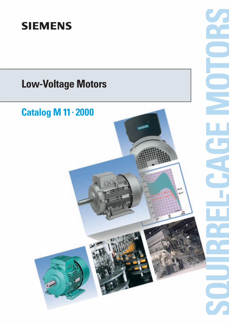
Catalog M 11 · 2000
Low-Voltage Motors

Important:
The technical specifications contained in this catalog are provided as general information.The Operating Instructions and the information specified on the actual products are binding for installation,operation and maintenance.
âCOMBIMASTER, DURIGNIT, SIMOVERT are registered trademarks of Siemens.Other designations used in this catalog may be trademarks whose use by third parties for their own purposes could violaterights of the owners.
Á Technical data, selection and ordering data (order numbers), accessories and availability are subject to change.
Á All dimensions in this catalog are stated in millimeters.
Catalogs of theAutomation and Drives Group (A&D)
Further information can be obtained from our branchoffices listed in the appendix of this catalog
Automation & Drives CatalogInteractive catalogs on CD-ROM• Components for Automation & Drives CA 01
• Electrical Installation Technology ET 01
Analysis SystemsGas Analysis Equipment for the Process Industry PA 10
Process Analysis, Components for Sample Preparation PA 11
SIPAN Liquid Analysis PA 20
Drive SystemsVariable-Speed Drives
DC Motors DA 12
DC Drives Preferred Series up to 500 kW DA 12.1
DC Drives Preferred Series 215 kW to 1500 kW DA 12.2
SIMOREG Chassis Converters DA 21
SIMOREG Converter Cabinet Units DA 22
SIMOVERT PM Modular Converter Systems DA 45
SIEMOSYN Motors DA 48
MICROMASTER 420 DA 51.2
SIMOVERT A Current-Source DC Link Converters DA 62
SIMOVERT MV Medium-Voltage Drives DA 63
MICROMASTER, MIDIMASTER DA 64
Low-Voltage Motors for Variable-Speed Drives DA 65.3
SIMOVERT MASTERDRIVES Vector Control DA 65.10
SIMOVERT MASTERDRIVES Motion Control DA 65.11
SIMADYN D Control System DA 99
Automation Systems for Machine Tools SIMODRIVE NC 60.1
• AC Main Spindle Motors 1PH2, 1PH3, 1PH4, 1PH7
• AC Servomotors 1FK6, 1FN1, 1FS5, 1FT5, 1FT6
• Converter System SIMODRIVE 611
See under catalog heading „SINUMERIK & SIMODRIVE“
Low-Voltage Three-Phase-Motors
• Project Manual M 10
• Squirrel-Cage Motors, Totally Enclosed, Fan-Cooled M 11
Drive and Control Components for Hoisting Equipment HE 1
Automation Systems for Machine ToolsSINUMERIK & SIMODRIVE• Ordering Catalog NC 60.1
• Cables, Connectors and System Components NC Z
Human Machine Interface Products/Systems SIMATIC HMI
ST 80
SIMATIC Industrial Automation SystemsSIMATIC PCS Process Control System ST 45
SIMATIC S5/PC/505 Automation Systems ST 50
Components for Totally Integrated Automation ST 70
Supplementary Components ST 71
SIMATIC PCS 7 Process Control System ST PCS 7
Electrical Installation TechnologyProtective Switching and Fuse SystemsBuilding Management Systems with instabus EIB
I 2.1
Program Overview Modular Devices I 2.11
STAB Wall-Mounting Distribution Boards I 2.31
SIKUS Floor-Mounting Distribution Boards I 2.32
8PU Busway System I 2.36
Systems Engineering CatalogPower supplies SITOP power KT 10.1
System cables SIMATIC TOP connect KT 10.2
MOBY Identification Systems KT 21
Industrial Microcomputers SICOMP KT 51
Printers and Monitors for Automation and Drives KT 61
Cabinet Packaging System for SIMATIC PCS 7 KT 71
Industrial Communication and Field Devices IK PI
Low-Voltage Controls and DistributionLow-Voltage Controlgear, Switchgear and Systems NS K
Communication-Capable SIRIUS NET Controlgear,Controlgear, SIGUARD Safety Systems,Control and Signalling Devices, Switchgear,Transformers and DC Power Supplies,Main- and EMERGENCY-STOP Switches,Control Switches, Terminal Blocks
SIGNUM Metallic 3SB3
Products and Systemsfor Low-Voltage Power Distribution
NS PS
TELEPERM M Process Control SystemSIMATIC PCS 7 Process Control System ST PCS 7
AS 235, AS 235H and AS 235K automation systems PLT 111
AS 388/TM and AS 488/TM automation systems PLT 112
OS 525 operating and monitoring system PLT 122
Operating and monitoring with WinCC/TM PLT 123
CS 275 bus system PLT 130
Process EngineeringField Instruments for Process AutomationMeasuring Instruments for Pressure, Differential Pressure, Flow, Level and Temperature, Positioners and Liquid Meters
FI 01
SITRANS LR FI 01
SIWAREX Weighing Systems KT 30
Process Recorders, Flush-mounted Recorders in Standardized Cases
MP 20
Process Recorders, Spare Parts, Accessoriesand Consumable Material for Older Designs of Recorders
MP 20.1
SIPART, Controllers, Software MP 31
Vacuum Pumps/CompressorsOil-Free Vacuum Pumps, Compressors (Blowers),Radial Blowers, Liquid Pumps
PV
PumpsVacuum Pumps and Compressors, System ELMO-F Cat. Sheets PF
Vacuum Pumps and Compressors, System ELMO-G Cat. Sheets PG
System SolutionsApplications, Products and Services for Industry SL 01
Automation Solutions in the Plastic Industry
• with SIMATIC S7 SL 10
• with SIMATIC S5 ST 58
A&D/U3/En 23.08.00
http://www.ad.siemens.de
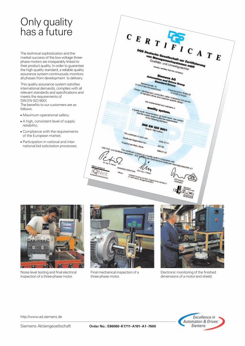
Only qualityhas a future
The technical sophistication and themarket success of the low-voltage three-phase motors are inseparably linked totheir product quality. In order to guaranteethe high quality standard, a reliable qualityassurance system continuously monitorsall phases from development to delivery.
This quality assurance system satisfiesinternational demands, complies with allrelevant standards and specifications andmeets the requirements ofDIN EN ISO 9001.The benefits to our customers are asfollows:
Á Maximum operational safety;
Á A high, consistent level of supplyreliability;
Á Compliance with the requirementsof the European market;
Á Participation in national and inter-national bid solicitation processes.
Electronic monitoring of the finisheddimensions of a motor end shield.
Final mechanical inspection of athree-phase motor.
Noise level testing and final electricalinspection of a three-phase motor.
Siemens Aktiengesellschaft Order No.: E86060–K1711–A101–A1–7600

sSquirrel-Cage M
otorsLow
-Voltage Motors
Catalog M 11 · 2000

s
Low-VoltageMotorsSquirrel-Cage MotorsTotally Enclosed,Fan-Cooled
Catalog M 11× 2000Supersedes: Catalog M 11× 1999
Introduction
Technical Information
Basic DesignAluminum enclosureCast-iron enclosurefor converter-fed operation
COMBIMASTERMotors with converters
Increased SafetyEEx e II type of protection
Explosion-Proof EnclosureEEx de IIC type of protection
Dimensions
Accessories and Spare Parts
Appendix
8
7
3
4
5
6
2
1
9© Siemens AG 2000
Technology which proves our know-how
1/2 Siemens M 11 · 2000
1
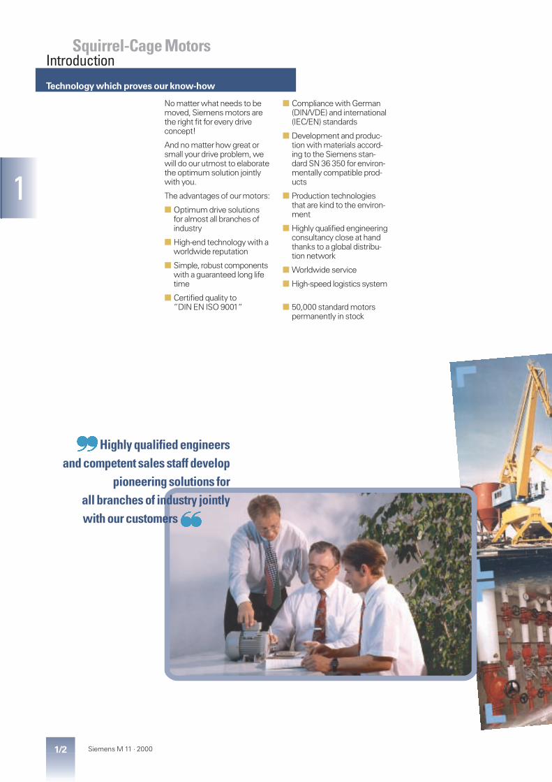
Squirrel-Cage MotorsIntroduction
No matter what needs to bemoved, Siemens motors arethe right fit for every driveconcept!
And no matter how great orsmall your drive problem, wewill do our utmost to elaboratethe optimum solution jointlywith you.
The advantages of our motors:
■ Optimum drive solutionsfor almost all branches ofindustry
■ High-end technology with aworldwide reputation
■ Simple, robust componentswith a guaranteed long lifetime
■ Certified quality to”DIN EN ISO 9001“
■ Compliance with German(DIN/VDE) and international(IEC/EN) standards
■ Development and produc-tion with materials accord-ing to the Siemens stan-dard SN 36 350 for environ-mentally compatible prod-ucts
■ Production technologiesthat are kind to the environ-ment
■ Highly qualified engineeringconsultancy close at handthanks to a global distribu-tion network
■ Worldwide service
■ High-speed logistics system
■ 50,000 standard motorspermanently in stock
Highly qualified engineersand competent sales staff develop
pioneering solutions forall branches of industry jointlywith our customers}
~
Low-voltage motorsTotally enclosed, fan-cooled,degree of protection IP 55
1/3Siemens M 11 · 2000
1
Squirrel-Cage MotorsIntroduction
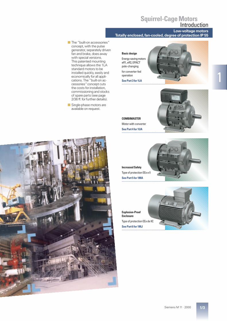
■ The ”built-on accessories“concept, with the pulsegenerator, separately drivenfan and brake, does awaywith special versions.This patented mountingtechnique allows the 1LAstandard motors to beinstalled quickly, easily andeconomically for all appli-cations. The ”built-on ac-cessories“concept cutsthe costs for installation,commissioning and stocksof spare parts (see page2/36 ff. for further details).
■ Single-phase motors areavailable on request.
Explosion-ProofEnclosure
Type of protection EEx de llC
See Part 6 for 1MJ...........................................................................................
COMBIMASTER
Motor with converter
See Part 4 for 1UA...........................................................................................
Basic design
Energy-savingmotorseff1, eff2, EPACTpole-changing
for converter-fedoperation
See Part 3 for 1LA...........................................................................................
Increased Safety
Type of protection EEx e ll
See Part 5 for 1MA...........................................................................................

Terminal boxpage 2/18
Connectionpage 2/18
Cooling and ventilationpage 2/16
Noisepage 2/17
Insulation and windingpage 2/14
Bearingspage 2/24
Selection of bearingspage 2/25
Bearing arrangementspage 2/27
Shaft extensionpage 2/32
Motor torquepage 2/9
Torque characteristicspage 2/10
Paint finishpage 2/35
Rating platepage 2/8
Types ofconstructionpage 2/22
Frame designpage 2/15

2/1Siemens M 11 · 2000
2
General data2/2 Order number structure2/3 Standards and specifications,
tolerances, motors for the U.S. market2/4 Use in various zones,
energy-saving motors to CEMEP
Electrical dataMechanical data
2/5 Voltage and frequency2/7 Table of rated output at 60 Hz2/8 Rated output, rating plate2/9 Efficiency and power factor,
rated motor torque2/10 Torque characteristics2/14 Restarting against residual field and opposite
phase, insulation, motor protection2/15 Anti-condensation heaters,
degrees of protection, frame design2/16 Cooling and ventilation2/17 Noise2/18 Terminal boxes2/22 Types of construction2/24 Bearings2/25 Selection of bearings2/27 Bearing arrangements2/29 Maximum cantilever forces2/32 Mechanical balance quality, shaft extensions2/33 Maximum axial loading2/35 Paint finish2/36 Modular technology
Squirrel-Cage MotorsTechnical
Information
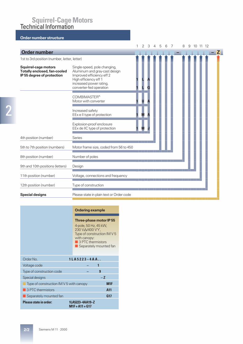
Order number structure
2/2 Siemens M 11 · 2000
2
Squirrel-Cage MotorsTechnical Information
1 2 3 4 5 6 7 8 9 10 11 12
Order number – – Z1st to 3rd position (number, letter, letter)
Squirrel-cage motorsTotally enclosed, fan-cooledIP 55 degree of protection
Single-speed, pole changing,Aluminum and gray-cast designImproved efficiency eff 2High efficiency eff 1increased power rating,converter-fed operation
COMBIMASTERâ
Motor with converter
Increased safetyEEx e II type of protection
Explosion-proof enclosureEEx de IIC type of protection
4th position (number) Series
5th to 7th position (numbers) Motor frame size, coded from 56 to 450
8th position (number) Number of poles
9th and 10th positions (letters) Design
11th position (number) Voltage, connections and frequency
12th position (number) Type of construction
Special designs Please state in plain text or Order code
1 U A
1 L A
1 L G
Ordering example
Three-phase motor IP 554-pole, 50 Hz, 45 kW,230 VB/400 V*,Type of construction IM V 5with canopy:■ 3 PTC thermistors■ Separately mounted fan
Order No. 1 L A 5 2 2 3 – 4 A A . .
Voltage code – 1
Type of construction code – 9
Special designs – Z
■ Type of construction IM V 5 with canopy M1F
■ 3 PTC thermistors A11
■ Separately mounted fan G17
Please state in order: 1LA5223–4AA19–ZM1F + A11 + G17
1 M J
1 M A

Standards and specifications, tolerances
2/3Siemens M 11 · 2000
2
Squirrel-Cage MotorsTechnical Information
Title DIN/EN IEC
General requirements forrotating electrical machines
DIN EN 60 034-1 IEC 60 034-1,IEC 60 085
Three-phase induction motors forgeneral use with standardizeddimensions and outputs
pr EN 50 347 IEC 60 072fixing dimen-sions only
Starting performance ofrotating electrical machines
DIN EN 60 034-12 IEC 60 034-12
Terminal designations anddirection of rotation, rotatingelectrical machines
DIN VDE 0530Part 8
IEC 60 034-8
Types of construction andinstallation
DIN EN 60 034-7 IEC 60 034-7
Entry into the terminal box DIN 42 925 –
Built-in thermal protection – IEC 60 034-11
Noise emission limits forrotating electrical machines
DIN EN 60 034-9 IEC 60 034-9
IEC standard voltages DIN IEC 60 038 IEC 60 038
Methods of coolingrotating electrical machines
DIN EN 60 034-6 IEC 60 034-6
Vibration severity ofrotating electrical machines
DIN EN 60 034-14 IEC 60 034-14
Degrees of protection ofrotating electrical machines
DIN EN 60 034-5 IEC 60 034-5
Additional for EEx motors:
General requirements DIN EN 50 014 IEC 79-0
Explosion-proof enclosure “d” DIN EN 50 018 IEC 79-1
Increased safety “e” DIN EN 50 019 IEC 79-7
The following tolerances arepermitted according toDIN EN 60 034:
Efficiency atPN ≤ 50 kW – 0.15 (1 – h)PN > 50 kW – 0.1 (1 – h)
with h being a decimal number.
Power factor –1– cos j
6Minimum 0.02Maximum 0.07
Slip ±20 %1)Locked-rotor curr. +20 %Locked-rotor –15 % totorque +25 %Breakdown torque –10 %Moment of inertia ±10 %
For type 1MA motors:
Add 10 % to the certified valuesfor the locked-rotor current.
National standards
The motors comply with variousnational standards. The followinghave been harmonized with IECpublication 60 034-1 or replacedby DIN EN 60 034-1, so that themotors can be operated at normalrated outputs.
For explosion-proof motors:
■ Since these motors complywith the European standardsEN 50 014, EN 50 018 andEN 50 019, all member statesof the EU recognize the testcertificates issued by the“Physikalisch-TechnischeBundesanstalt”(PTB). Theremaining members ofCENELEC also accept thecertificates, except for Switzer-land (several motors have SEVapprovals for Switzerland).
AS 1359 Australia (higher rated-output assignmentthan stated in DIN 42 673 for frame size250 M or larger)
BS 5000BS 4999
United Kingdom
CEI 2-3 Italy
CSA C22.2, No. 100 Canada
IS 325IS 4722
India
NBNC 51-101 Belgium
NEK – IEC 60 034-1 Norway
NEN 3173 Netherlands
NF C 51 France
SS 426 01 01 Sweden superseded by EN 60 034-1
SEV 3009 Switzerland superseded by EN 60 034-1
In 1997,an act was passed in theUSA to define minimum efficien-cies for low-voltage three-phasemotors (EPACT). In Canada there isan act which is largely identical, al-though it is based on different veri-fication methods.Hence,most ofthe low-voltage three-phase mo-tors exported to the U.S.orCanadamust comply with legal require-ments on efficiency.
USA
The act requires minimum effi-ciencies for 2, 4 and 6-pole 60 Hzmotors in the power range of 1 to200 hp (0.75 to 160 kW). The effi-ciency of these motors is verifiedusing IEEE 112-1992, test methodB. The act lays down that theefficiency at full load must beincluded on the rating plate. Therequired proof of an accreditedtesting laboratory is producedwith each unit.
NEMA
The motors with increased effi-ciency according to EPACT are de-signed to meet the NEMA MG1electrical standard, and markedaccordingly. The mechanical de-sign of all motors is compliant onlyto IEC, not to NEMA. For all mo-tors, Design D (torque characteris-tic according to NEMA) meansspecial design. For 1LA8 motors,Design A, B, C and D (torque char-acteristic according to NEMA)means special design (requestnecessary). All 1LA motors thatmatch Division 2 can be imple-mented according toNEC-ANSI-C1, Division 2, Class Iand II, Group A, B, D.
Canada
The motors with increased effi-ciency according to EPACT mustfulfill the efficiency regulations onthe basis of the CSA standard.The motors must carry a CSA-Eenergy verification mark.
CSA
All 1LA motors are certified ac-cording to the Canadian CSA stan-dard (except when with separateventilation or brake). The motorsmust be ordered with the codeD40, voltage code “9”and thecode for voltage and frequency(extra charge). The motors arestamped with the CSA ratingplate with the rated voltage andthe permitted voltage tolerance of±10 %. The motors must have in-creased efficiency according toEPACT. The rating plates aremarked with the CSA-E sign.
Motors for the U.S.marketElectrical tolerances
1) ±30 % permitted for motors< 1 kW

Standards and specifications
2/4 Siemens M 11 · 2000
2
Squirrel-Cage MotorsTechnical Information
K30
Motors up to frame size 355 canbe supplied in accordance withthe “Technical Requirements”ofVIK (Verband der IndustriellenEnergie- und Kraftwirtschaft).
Not possible for 1LA5 motors,1LA6 motors are delivered.
A low-noise design is additionallyrequired for 2-pole 1LA6 and 1LA6motors, frame sizes 315 S and315 L, as well as for all 2-pole1MJ8 motors (Order Code K37 orK38).
Take account of the rated-outputassignment and the dimensionsof 1LA8 motors. The terminal boxof 1LA8 357 (2 and 4-pole) cannotbe rotated 4 x 90°.
Vertically mounted motors withthe shaft extension pointingdownwards must be providedwith a canopy.
Frame sizes 400 and 450 are notavailable with the VIK design.
Converter-fed operation availableon request.
Zone 2 to DIN VDE 0165
L84 System operation
L87 for converter-fed oper.Pump and fan drives
M03 for converter-fed oper.Constant-torque drive
The 1LA motors are suitable foruse in hazardous areas of Zone 2for temperature rises T1 to T3.The maximum surface tempera-ture during service must be lessthan the temperature limit for theparticular temperature rise. Theventilation system must complywith DIN EN 50 014.
Use in accordance with class Fon request.
Vertical mounted motors withthe shaft extension pointingdownwards must be providedwith a canopy.
The 1LA motors are fitted withPTC thermistors when operatedwith converters (standard designfor 1LA8 motors). 1LA6 motorshave an additional PTC thermistorin the terminal box. With somemotors the limit speed has to bereduced or a metal fan fitted.
Zone 2 to IEC 60 079-15
L85 System operation
L88 for converter-fed oper.Pump and fan drives
M04 for converter-fed oper.Constant-torque drive
IEC 60 079-15 states the type ofprotection Ex nA II T3.
The same requirements must bemet as with DIN VDE 0165. Themotors are fitted with a metal ter-minal box.
A PTB certificate is available.
The rating plate or the supplemen-tary rating plate is stamped with:Ex nA II T3 acc. to IEC 60 079-15.
Zone 2 to BS 5000, Part 16
L86 System operation
L89 for converter-fed oper.Pump and fan drives
M05 for converter-fed oper.Constant-torque drive
The 1LA5 and 1LA7 motors are fit-ted with an external earthing ter-minal in addition to DIN VDE 0165.
Please enquire for further detailsabout 1LA8 motors.
The rating plate or supplementaryrating plate is stamped with:ExN II T3 in accordance withBS 5000/16.
Zone 21 to IEC 61 241,
EN 50 281, ATEX 118a
M34 System operation
M38 for converter-fed op.
Zone 22 to IEC 61 241,
EN 50 281, ATEX 118a
M35 System operation
M39 for converter-fed op.
The 1LA/1LG motors are suitablefor use in areas with danger ofdust explosions if various precau-tions are taken. Surface tempera-tures may not exceed 125 °C dur-ing normal operation.
The motor version for non-conduc-tive dust, degree of protectionIP 55, is designed for Zone 22. Themotors obtain an outer groundterminal.
VIK design
An ATEX certification isrequired for Zone 21, and adeclaration of EC conformityfor Zone 22.
Energy-saving motors with efficiency classification accordingto CEMEP
Low-voltage motors in the outputrange between 1.1 to 90 kW,2- and 4-pole, are marked accord-ing to the CEMEP Agreementwith efficiency class (Im-proved efficiency) or (HighEfficiency). The active motor parts
were optimised to fulfil the re-quirements on the efficiencyclasses and . The proce-dure to determine the efficiency isbased on the loss-summationmethod according toIEC 60 034-2.
Type of protection EEx de IIC
explosion-proof enclosure “d“
■ All 1MJ motors are certifiedfor the EEx de IIC type ofprotection.
The frames are designed towithstand internal explosionand transmission. An ignitingflame to the outside is impos-sible. The frame temperature isless than the ignition tempera-ture of the gases for tempera-ture class T4.
Temperature class T6 and anexplosion-proof terminal boxare available to order.
■ The PTB certificate of confor-mity, which is valid up to tem-perature class T4, covers thefollowing deviations: differentcoolant temperature (–20 °C to+60 °C), site altitude, frequencyand rated duty type, pole-changing motors, fitting oftemperature sensors and con-verter-fed operation with fittingof temperature sensors.
If 1MJ motors are used withconverters, they may have tobe fitted with special terminalboxes (please inquire).
EEx e II type of protection
increased safety “e“
■ The 1MA motors are certifiedfor the EEx e II type of protec-tion for temperature class T1 toT4 up to frame size 90 L, and fortemperature classes T1 to T3for frame size 100 L or larger.Higher temperature classes areavailable to order.
With the exception of the2-pole motors with frame size225 M or larger, all the motorsare simultaneously suitablefor T1/T2 or T3 and the corre-sponding rated outputs(standard design). A new orsupplementary certificate maybe needed for non-standard de-signs (different frequency, out-put, coolant temperature, sitealtitude etc.). It is essential forthe temperature class to bespecified because if not, thestandard design for T1/T2 andT3 will be certified (double cer-tification fee).
Use of 1LA motors in hazardous areas
Design and certification of explosion-proof motors

Voltage and frequency
2/5Siemens M 11 · 2000
2
Squirrel-Cage MotorsTechnical Information
Voltages Rated voltage range
1LA, 1LG and 1MJ motors
230 VB/400 V*, 50 Hz400 VB/690 V*, 50 Hz
220 – 240 VB/380 – 420 V*, 50 Hz380 – 420 VB/660 – 725 V*, 50 Hz
1LA and 1LG motors with second rating plate, frame sizes 56 to 315 M
460 V, 60 Hz 440 – 480 V, 60 Hz
1MA motors
230 VB/400 V*, 50 Hz400 VB/690 V*, 50 Hz
218 – 242 VB/380 – 420 V*, 50 Hz380 – 420 VB/655 – 725 V*, 50 Hz
The tolerance laid down byDIN EN 60 034-1 applies to allconverter-fed 1LA8 motors,i.e. no rated voltage range isspecified.
No rated voltage range isspecified for 1MA8 motors.
The tolerance specified byDIN EN 60 034-1 applies to allnon-standard voltages.
Order Codes have been allocatedfor a number of non-standardvoltages(11th position of Order No. = 9).
Plain texts for voltage, connectionand frequency
L1X ■ Standard winding
L1Y ■ Non-standard winding
■ This Order Code onlydetermines the price.
When ordering, please alsostate:the voltage, frequency,connection and ratedoutput in kW.
■ With 1LA9 and 1LA6,eff 1/EPACT, or increasedoutput: only L1Ywiring.
Voltageat
50 Hz
Requiredoutput at
50 Hz
OrderCode for
50 Hz
Frame sizes for motors
1LA5/1LA71LG8
1LA6,1LA8 1MA6,1MA81MA7
1MJ6,1MJ8
220 VB/380 V* – L1R 56 – 225 180 – 315 63 – 315 71 – 315
380 VB/660 V* – L1L 56 – 225 180 – 450 63 – 355 71 – 450
415 V*415 VB
––
L1CL1D
56 – 22556 – 225
180 – 450180 – 450
63 – 35563 – 355
71 – 45071 – 450
60 Hz 60 Hz 60 Hz
220 VB/380 V*220 VB/380 V*
50-Hz output60-Hz output
L2AL2B
56 – 22556 – 225
180 – 315 M180 – 315 M
63 – 315 M–
71 – 315 M71 – 315 M
380 VB/660 V*380 VB/660 V*
50-Hz output60-Hz output
L2CL2D
56 – 22556 – 225
180 – 450180 – 450
63 – 355–
71 – 45071 – 450
440 V*440 V*440 VB440 VB
50-Hz output60-Hz output50-Hz output60-Hz output
L2QL2WL2RL2X
56 – 22556 – 22556 – 22556 – 225
180 – 315 M180 – 315 M180 – 450180 – 450
63 – 315 M–63 – 355–
71 – 315 M71 – 315 M71 – 45071 – 450
460 V*460 V*460 VB460 VB
50-Hz output60-Hz output50-Hz output60-Hz output
L2SL2EL2TL2F
56 – 225–56 – 225–
180 – 315 M–180 – 450315 L – 450
63 – 315 M–63 – 355–
71 – 315 M71 – 315 M71 – 45071 – 450
575 V*575 V*575 VB575 VB
50-Hz output60-Hz output50-Hz output60-Hz output
L2UL2LL2VL2M
56 – 22556 – 22556 – 22556 – 225
180 – 315 M180 – 315 M180 – 450180 – 450
63 – 315 M–63 – 355–
71 – 315 M71 – 315 M71 – 45071 – 450
60 Hz 60 Hz
Pole-changingmotors
220 V220 V
50-Hz output60-Hz output
L4AL4B
56 – 22556 – 225
––
––
––
380 V380 V
50-Hz output60-Hz output
L4CL4D
56 – 22556 – 225
180 – 315180 – 315
––
––
440 V440 V
50-Hz output60-Hz output
L4GL4E
56 – 22556 – 225
180 – 315180 – 315
––
––
460 V460 V
50-Hz output60-Hz output
L4JL4H
56 – 225 M56 – 225 M
180 – 315180 – 315
––
––
575 V575 V
50-Hz output60-Hz output
L4NL4M
56 – 225 M56 – 225 M
180 – 315180 – 315
––
––
The maximum current isspecified in the rated voltagerange.
DIN EN 60 034-1 Part 1 lays downa voltage tolerance of ±5 % formotors (Zone A).
The tolerance for the rated voltagerange is ±5 % in accordance withDIN EN 60 034, and the permissi-ble limit temperature for the tem-perature rise in question can beexceeded by 10 K taking advan-tage of this voltage tolerance.
See page 2/8 for details of therating plate inscriptions and exam-ples.
The selection and ordering datastates the rated current at 400 V.The rated currents at 380 V and420 V are listed in the table onpage 2/6.
DIN IEC 60 038 specifies a toler-ance of ±10 % for system volt-ages of 230 V, 400 V and 690 V.
For 1MA motors:
For non-standard frequencies thetE output values may differ fromthose stated in the selectiontables; in this case, a new or sup-plementary certificate is needed.
The AUSTER software providesdetails of designs already ap-proved at 60 Hz.
Overload protection with phasefailure tripping must be providedfor a B connection.
Standard voltages
Other voltages and/or frequencies
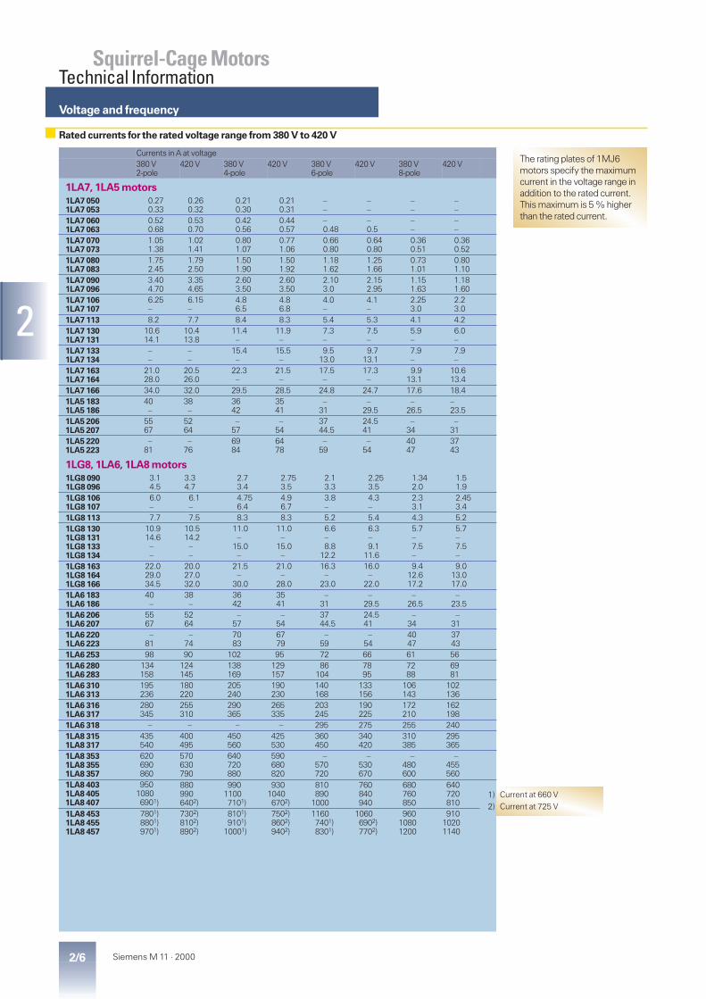
Voltage and frequency
2/6 Siemens M 11 · 2000
2
Squirrel-Cage MotorsTechnical Information
Currents in A at voltage380 V2-pole
420 V 380 V4-pole
420 V 380 V6-pole
420 V 380 V8-pole
420 V
1LA7, 1LA5 motors1LA7 0501LA7 053
0.270.33
0.260.32
0.210.30
0.210.31
––
––
––
––
1LA7 0601LA7 063
0.520.68
0.530.70
0.420.56
0.440.57
–0.48
–0.5
––
––
1LA7 0701LA7 073
1.051.38
1.021.41
0.801.07
0.771.06
0.660.80
0.640.80
0.360.51
0.360.52
1LA7 0801LA7 083
1.752.45
1.792.50
1.501.90
1.501.92
1.181.62
1.251.66
0.731.01
0.801.10
1LA7 0901LA7 096
3.404.70
3.354.65
2.603.50
2.603.50
2.103.0
2.152.95
1.151.63
1.181.60
1LA7 1061LA7 107
6.25–
6.15–
4.86.5
4.86.8
4.0–
4.1–
2.253.0
2.23.0
1LA7 113 8.2 7.7 8.4 8.3 5.4 5.3 4.1 4.21LA7 1301LA7 131
10.614.1
10.413.8
11.4–
11.9–
7.3–
7.5–
5.9–
6.0–
1LA7 1331LA7 134
––
––
15.4–
15.5–
9.513.0
9.713.1
7.9–
7.9–
1LA7 1631LA7 164
21.028.0
20.526.0
22.3–
21.5–
17.5–
17.3–
9.913.1
10.613.4
1LA7 166 34.0 32.0 29.5 28.5 24.8 24.7 17.6 18.41LA5 1831LA5 186
40–
38–
3642
3541
–31
–29.5
–26.5
–23.5
1LA5 2061LA5 207
5567
5264
–57
–54
3744.5
24.541
–34
–31
1LA5 2201LA5 223
–81
–76
6984
6478
–59
–54
4047
3743
1LG8, 1LA6, 1LA8 motors1LG8 0901LG8 096
3.14.5
3.34.7
2.73.4
2.753.5
2.13.3
2.253.5
1.342.0
1.51.9
1LG8 1061LG8 107
6.0–
6.1–
4.756.4
4.96.7
3.8–
4.3–
2.33.1
2.453.4
1LG8 113 7.7 7.5 8.3 8.3 5.2 5.4 4.3 5.21LG8 1301LG8 1311LG8 1331LG8 134
10.914.6––
10.514.2––
11.0–
15.0–
11.0–
15.0–
6.6–8.8
12.2
6.3–9.1
11.6
5.7–7.5–
5.7–7.5–
1LG8 1631LG8 1641LG8 166
22.029.034.5
20.027.032.0
21.5–
30.0
21.0–
28.0
16.3–
23.0
16.0–
22.0
9.412.617.2
9.013.017.0
1LA6 1831LA6 186
40–
38–
3642
3541
–31
–29.5
–26.5
–23.5
1LA6 2061LA6 207
5567
5264
–57
–54
3744.5
24.541
–34
–31
1LA6 2201LA6 223
–81
–74
7083
6779
–59
–54
4047
3743
1LA6 253 98 90 102 95 72 66 61 561LA6 2801LA6 283
134158
124145
138169
129157
86104
7895
7288
6981
1LA6 3101LA6 313
195236
180220
205240
190230
140168
133156
106143
102136
1LA6 3161LA6 317
280345
255310
290365
265335
203245
190225
172210
162198
1LA6 318 – – – – 295 275 255 2401LA8 3151LA8 317
435540
400495
450560
425530
360450
340420
310385
295365
1LA8 3531LA8 3551LA8 357
620690860
570630790
640720880
590680820
–570720
–530670
–480600
–455560
1LA8 4031LA8 4051LA8 407
95010806901)
8809906402)
99011007101)
93010406702)
810890
1000
760840940
680760850
640720810
1LA8 4531LA8 4551LA8 457
7801)8801)9701)
7302)8102)8902)
8101)9101)
10001)
7502)8602)9402)
11607401)8301)
10606902)7702)
96010801200
91010201140
1) Current at 660 V2) Current at 725 V
The rating plates of 1MJ6motors specify the maximumcurrent in the voltage range inaddition to the rated current.This maximum is 5 % higherthan the rated current.
Rated currents for the rated voltage range from 380 V to 420 V

Rated outputs at 60 Hz
2/7Siemens M 11 · 2000
2
Squirrel-Cage MotorsTechnical Information
Motor type Maximum output at 60 Hz for voltagesbetween 220 V or 380 V and 725 V2-polekW
4-polekW
6-polekW
8-polekW
1LA7, 1LA5 , 1MJ6 motors1LA7 0501LA7 053
––
0.1050.14
0.070.105
––
––
1LA7 0601LA7 063
––
0.210.29
0.140.21
–0.1
––
1LA7 0701LA7 073
1MJ6 0701MJ6 073
0.430.63
0.290.43
0.210.29
0.10.14
1LA7 0801LA7 083
1MJ6 0801MJ6 083
0.861.3
0.630.86
0.430.63
0.210.29
1LA7 0901LA7 096
1MJ6 0961MJ6 097
1.752.55
1.31.75
0.861.3
0.430.63
1LA7 1061LA7 107
1MJ6 1061MJ6 107
3.45–
2.553.45
1.75–
0.861.3
1LA7 113 1MJ6 113 4.6 4.6 2.55 1.751LA7 1301LA7 131
1MJ6 1301MJ6 131
6.38.6
6.3–
3.45–
2.55–
1LA7 1331LA7 134
1MJ6 1331MJ6 134
––
8.6–
4.66.3
3.45–
1LA7 1631LA7 164
1MJ6 1631MJ6 164
12.617.3
12.6–
8.6–
4.66.3
1LA7 166 1MJ6 166 21.3 17.3 12.6 8.61LA5 1831LA5 186
1MJ6 1831MJ6 186
24.5–
21.325.3
–18
–13.2
1LA5 2061LA5 207
1MJ6 2061MJ6 207
33.541.5
–34.5
2226.5
–18
1LA5 2201LA5 223
––
–51
42.552
–36
2226.5
Motor type Maximum output at 60 Hz for voltagesbetween 220 V or 380 V and 725 V2-polekW
4-polekW
6-polekW
8-polekW
1LG8, 1LA6, 1MJ6, 1LA8, 1MJ8 motors1LG8 0901LG8 096
––
1.752.55
1.31.75
0.861.3
0.430.63
1LG8 1061LG8 107
––
3.45–
2.553.45
1.75–
0.861.3
1LG8 113 – 4.6 4.6 2.55 1.751LG8 1301LG8 131
––
6.38.6
6.3–
3.45–
2.55–
1LG8 1331LG8 134
––
––
8.6–
4.66.3
3.45–
1LG8 1631LG8 164
––
12.617.3
12.6–
8.6–
4.66.3
1LG8 166 – 21.3 17.3 12.6 8.61LA6 1831LA6 186
––
24.5–
21.325.3
–18
–13.2
1LA6 2061LA6 207
––
33.541.5
–34.5
2226.5
–18
1LA6 2201LA6 223
1MJ6 2201MJ6 223
–51
42.552
–36
2226.5
1LA6 253 1MJ6 253 62 63 44.5 361LA6 2801LA6 283
1MJ6 2801MJ6 283
84101
86104
5466
44.554
1LA6 3101LA6 313
1MJ6 3101MJ6 313
123148
127152
90108
6690
1LA6 3161LA6 3171LA6 318
–––
180224
–
184230
–
127152184
104127152
1LA8 3151LA8 317
––
280353
288362
230288
184230
1LA8 3531LA8 3551LA8 357
–––
398448560
408460575
–362460
–288362
1LA8 4031LA8 4051LA8 407
–––
616693781
644725817
518575644
408460518
1LA8 4531LA8 4551LA8 457
–––
–––
92010401150
725817920
575644725
–––
1MJ8 3131MJ8 3141MJ8 316
190–
240
180–
220
132145175
100120145
––––
1MJ8 3531MJ8 3541MJ8 3561MJ8 357
280–
350–
250280315355
225–
280–
180–
225–
–––
1MJ8 4001MJ8 4031MJ8 406
400450
–
400450500
315355400
280315355
–––
1MJ8 4531MJ8 4561MJ8 457
500560630
560630710
450500560
400450500
Table of rated output at 60 Hz for single-speed motors
Speed increases to approx. 120 % in relation to 50 Hz motors.
For 60 Hz, the rated outputvalues can be increased using thecorrection factors in the tableabove.
The output is increased separatelyfor each number of poles, i.e. for6-/4-pole motors, frame sizes180 to 315 and 60 Hz the 6-polerating can be increased by 20 %and the 4-pole rating by 15%.
Table of rated output at 60 Hz for pole-changing motors
Frame size No. of poles Correction factorfor 60 Hz outputfor voltages between 220 Vor 380 V and 725 V
56 to 160180 to 315
2 to 8246 and 8
1.151.121.151.2
Possible combinations of 2-pole motors
Frame size Horizontal motor Vertical motor50 Hz with foot 60 Hz with foot 50 Hz with flange 60 Hz with flange 50 Hz 60 Hz
56 to 315 M x x x x x x315 L x x – – x on request315 x x – – x x355 and 400 x x – – x –450 x – – – x –

Output · Rating plate
2/8 Siemens M 11 · 2000
2
Squirrel-Cage MotorsTechnical Information
■ The rated output refers tocontinuous duty according toDIN EN 60 034-1 at a frequencyof 50 Hz, a coolant temperature(CT) of 40 °C and a site altitudeof up to 1000 m above sea level(ASL).
The motors are designed for classF and used in class B. If the actualoperating conditions deviate fromthis class, the maximum outputshould be adjusted according tothe following tables.
Altitude abovesea level
Coolanttemperature in °C
in m <30 30–40 451000150020002500300035004000
1.071.041.000.960.920.880.82
1.000.970.940.900.860.820.77
0.960.930.900.860.820.790.74
Altitude abovesea level
Coolanttemperature in °C
in m 50 55 601000150020002500300035004000
0.920.890.860.830.790.750.71
0.870.840.820.780.750.710.67
0.820.790.770.740.700.670.63
The coolant temperature and thealtitude are rounded up to thenearest 5 °C or 500 m.
■ Effective values, which must bestated when ordering, havebeen calculated for the follow-ing output ratings and coolanttemperatures (CT) of 45 °C and50 °C.
DIN-outputrating
Maximum outputat 50 Hzat CT 45 °C at CT 50 °C
kW kW kW111518.5
10.514.517.8
1013.817
223037
212935.5
2027.534
455575
435372
41.55169
90110132
86106127
83101122
145160180
139153173
133147166
200250280
192240269
184230258
315355400
302340384
290325368
450500560
432480538
414460515
630710800
605682768
580653736
9001000
864960
828920
■ For changes in the outputrating with class F utilization,see “DURIGNIT IR 2000insulation“ on page 2/14.
If utilised according to tempera-ture class B, motors intended forcoolant temperatures other than40 °C or altitudes greater than1000 m above sea level must al-ways be ordered with the suffix“–Z“ added to the Order No. andthe requirement stated in plaintext.
Additional derating of the outputwill result in a deterioration in per-formance due to the lower utiliza-tion factor of the motors.
For Order Codes for class F utiliza-tion, see “DURIGNIT IR 2000insulation“ on page 2/14.
For all motors:
The motors are intended to with-stand 1.5 times the rated currentfor up to 2 minutes at ratedvoltage and frequency(DIN EN 60 034).
Ambient temperature
All motors with the standard de-sign can be used at ambient tem-peratures between –20 °C and+40 °C. 1LA7 and 1LG8 motorscan be operated at temperaturesfrom –30 °C to +60 °C, at 40 °Cwith pulse duty factor 1.1, utiliza-tion of heat class F from 40 °Cwith reduction in power. For useup to +60 °C, there is a reductionin power.
Special design measures arenecessary for other ambient tem-peratures.
Inquiry is necessary if brakes areneeded for sub-zero tempera-tures.
M1-5
150b
3 ~ Mot. 1LA6 253-4AA60 250M No UC 0008/123432101 IM B3 Th.Cl. F
VHz
AkW cosj 1/min IA
/INTE
s Certif.No
IP
55
400 D
460 D
690 Y
50
60
56
97
97
55
63
0,87
0,87
1480
1780
Rotor SQU.CAGE EN 60 034 nmax=3700 1/min Gew./Wt0,44 t
380...420 VD , 102...95 A; 660...725 VY, 58...55 A 50 Hz
440...480 VD , 100...94 A, 60 Hz
DE
W0234
s
Examples ofrating plates
M1-5
149bs
3 ~ Mot.
IP 55
132 M / IM B3EN 60034 Th.Cl. F
50 Hz
Nr. E H984 6148 01 002
7,5 kW
26,5 / 15,3 A
1455 / min
220-240 / 380-420 V D / Y
26,5-27,0 / 15,3-15,6 Acosj 0,82
460 V Y
8,6 kW
14,7 A
1755 / min
440/480 V Y
15,0-15,2 Acosj 0,83230 / 400 V D / Y
SF 1,1
60 Hz
1 LA713 3-4AA10Type of
constr.
Serial No.Class
Service factor
50-Hz-data
60-Hz-data
Frame size
Order No.
Date of
manufacture
Degree of prot.
For all motors from 30 kg on theweight is indicated on the ratingplate.
A second rating plate can besupplied loose for all the motors(Order Code K31, extra charge).
In addition, a supplementary platewith the order specifications isavailable (Order Code Y82, extracharge).
For type 1MA and1ME motors:
With the exception of the 2-polemotors with frame size 225 M orlarger, all the motors are simulta-neously suitable for T1/T2 and T3and the corresponding rated out-puts (standard design). If therated output for T1/T2 differs fromthat for T3, the data for both out-puts is stated on separate ratingplates.
Rating plate
Motortype
Frame size Rating plate 50/60 data forinter-natio-nal
de de/en
fr/es
it pt ru 230/400 Vand 460 V
400/690 Vand 460 V
1LA7 all n n n
1LA5 all n n n
1LA9 all n n n
1LG8 all n n n
1LA6 180 and 200 n n n
1LA6 225 to 315 n l l l u n exceptBG 315L
1LA8 all n l l l u
1MA7 all n
1MA6 all n l l l u
1MA8 all n l l l u
1MJ6 71 to 160 n
1MJ6 180 to 315 n l l l u
1MJ8 all n u u u u
n Standard design
l no extra chargeu extra charge
double rating plate

Efficiency and power factor,rated torque
2/9Siemens M 11 · 2000
2
Squirrel-Cage MotorsTechnical Information
Efficiency and power factor
The efficiency h and power factorcosj values for each rated outputare listed in the selection tables inthe individual sections of thisCatalog.
For eff1 and eff2 motors, also the3/4 load efficiency is indicated inthe selection tables.
The part-load values stated inthe table opposite are averages;precise values can be providedon request.
Rated torque
The rated torque in Nm deliveredat the motor shaft is
M = 9.55 · P ·1000
nP Rated output in kWn Speed in rpm
■ If the voltage deviates fromits nominal value within theallowed limits, the locked-rotortorque, the pull-up torque andthe breakdown torque varywith the approximate squareof the value, while the locked-rotor current varies approxi-mately linearly.
In the case of squirrel-cagemotors, the locked-rotor torqueand the breakdown torque arelisted in the selection tables asmultiples of the rated torque.
The normal practice is to startsquirrel-cage motors directly on-line. The torque class indicatesthat with direct-on-line starting –even if there is –5% undervolt-age – it is possible to start up themotor against a load torque ofup to
160 % for CL 16 70 % for CL 7130 % for CL 13 50 % for CL 5100 % for CL 10
of the rated torque.
The diagrams show only typicalcharacteristics.
■ Please ask for advice if thetorque characteristic of thedriven machine is very close tothe scatter band of the motortorque characteristic.
For type 1MA and1ME motors
In the case of the standard designfor T1/T2 and T3 and differentrated outputs, the torque classspecified for the higher outputapplies.
Part-load efficiency % at1/4of full load
1/2 3/4 5/4
939290
969593.5
979695
979695
96.595.594.5
898887
92.591.591
949392
949392
93.592.591.5
868584
908988
919089
919089
908988
807978
878685
888786
888786
878685
767472
848382
858483
858483
83.582.581.5
706866
818079
828180
828180
80.579.578.5
646260
7775.574
79.578.577.5
797877
77.576.575
585655
737271
767574
767574
747372
545352
706867
737271
737271
717069
515049
666564
706967.5
706968
686766
484746
626160
66.56564
676665
656463
454443
595756
636260.5
646362
626160.5
4241
5554
59.558.5
6160
59.558.5
Part-load power factor at1/4of full load
1/2 3/4 5/4
0.700.650.63
0.860.850.83
0.900.890.88
0.920.910.90
0.920.910.90
0.610.570.53
0.800.780.76
0.860.850.84
0.890.880.87
0.890.880.87
0.510.490.47
0.750.730.71
0.830.810.80
0.860.850.84
0.860.860.85
0.450.430.41
0.690.670.66
0.790.770.76
0.830.820.81
0.840.830.82
0.400.380.36
0.650.630.61
0.750.740.72
0.800.790.78
0.810.800.80
0.340.320.30
0.590.580.56
0.710.700.69
0.770.760.75
0.790.780.78
0.290.280.270.26
0.550.540.520.50
0.680.670.630.62
0.740.730.720.71
0.770.770.760.76
4/44/4

Torque characteristics
2/10 Siemens M 11 · 2000
2
Squirrel-Cage MotorsTechnical Information
1 32
4 65
7 98
M1-5032
100
320
0
40
80
120
160
280
%
M / MN
200
240
0 50 100%0%50
SlipSynchr.Speed
A
CL 16
100
320
0
40
80
120
160
280
%
M / M N
200
240
0 50 100%0%50
M1-5038
SlipSynchr.Speed
A
CL 16
CL 13
100
320
0
40
80
120
160
280
%
M / M N
200
240
0 50 100%0%50
M1-5037
SlipSynchrSpeed
A
CL 16
CL 13
100
320
0
40
80
%
M / M N
200
240
0 50 100%0%50
M1-5035
160
280
120
SlipSynchr.Speed
A
CL 16
100
320
0
40
80
120
160
280
%
M / M N
200
240
0 50 100%0%50
M1-5034SlipSynchr.Speed
A
CL 16
100
320
0
40
80
120
160
280
%
M / M N
200
240
0 50 100%0%50
M1-5033
SlipSynchr.Speed
A
CL 16
In the following torque characteristics■ the torque is plotted as % of the rated value,■ the speed is plotted as % of the synchronous speed.CL Torque class
100
400
0
50
100
150
200
350
%
M / M N
250
300
0 50 100%0%50
M1-5203
SlipSynchr.Speed
A
CL 16
CL 13
100
320
0
40
80
120
160
280
%
M / M N
200
240
0 50 100%0%50
M1-5039
SlipSynchr.Speed
A
CL 13
CL 16
100
480
0
60
120
180
240
420
%
M / M N
300
360
0 50 100%0%50
M1-5204
SlipSynchr.Speed
A
CL 16
CL 13

Torque characteristics
2/11Siemens M 11 · 2000
2
Squirrel-Cage MotorsTechnical Information
10 1211
13 1514
16 1817
M1-5027
100
320
0
40
80
120
160
280
%
M / MN
200
240
0 50 100%0%50
SlipSynchr.Speed
A
CL 13
100
320
0
40
80
%
M / M N
200
240
0 50 100%0%50
M1-5146
160
280
120
SlipSynchr.Speed
A
CL 10
CL 13
100
320
0
40
80
%
M / M N
200
240
0 50 100%0%50
M1-5145
160
280
120
SlipSynchr.Speed
A
CL 10
CL 13
100
320
0
40
80
%
M / M N
200
240
0 50 100%0%50
M1-5144
160
280
120
SlipSynchr.Speed
A
CL 5
CL 7
100
320
0
40
80
%
M / M N
200
240
0 50 100%0%50
M1-5043
160
280
120
SlipSynchr.Speed
A
CL 13
100
320
0
40
80
120
160
280
%
M / M N
200
240
0 50 100%0%50
M1-5042SlipSynchr.Speed
A
CL 13
320
0
40
80
120
160
280
%
M / M N
200
240
0 50 100%
M1-5041
50100 0%SlipSynchr.Speed
A
CL 13
100
320
0
40
80
120
160
280
%
M / M N
200
240
0 50 100%0%50
M1-5040
SlipSynchr.Speed
A
CL 13
100
400
0
50
100
150
200
350
%
M / M N
250
300
0 50 100%0%50
M1-5205
SlipSynchr.Speed
A
CL 13
CL 16

Torque characteristics
2/12 Siemens M 11 · 2000
2
Squirrel-Cage MotorsTechnical Information
19 2120
22 2423
25 2726
M1-5029
100
320
0
40
80
120
160
280
%
M / MN
200
240
0 50 100%0%50
SlipSynchr.Speed
A
CL 13
100
320
0
40
80
%
M / M N
200
240
0 50 100%0%50
M1-5051
160
280
120
SlipSynchr.Speed
A
CL 7
M1-5028
100
320
0
40
80
120
160
280
%
M / M N
200
240
0 50 100%0%50
SlipSynchr.Speed
A
CL 10
CL 13
M1-5025
100
320
0
40
80
120
160
280
%
M / M N
200
240
0 50 100%0%50
SlipSynchr.Speed
A
CL 10
M1-5024
100
320
0
40
80
120
160
280
%
M / M N
200
240
0 50 100%0%50 Slip
Synchr.Speed
CL 10
A
100
320
0
40
80
%
M / M N
200
240
0 50 100%0%50
M1-5048
160
280
120
SlipSynchr.Speed
A
CL 10
100
320
0
40
80
%
M / M N
200
240
0 50 100%0%50
M1-5047
160
280
120
SlipSynchr.Speed
A
CL 10
M1-5031
100
320
0
40
80
120
160
280
%
M / MN
200
240
0 50 100%0%50
SlipSynchr.Speed
A
CL 13
M1-5030
100
320
0
40
80
120
160
280
%
M / MN
200
240
0 50 100%0%50
SlipSynchr.Speed
A
CL 13

Torque characteristics
2/13Siemens M 11 · 2000
2
Squirrel-Cage MotorsTechnical Information
28 3029
31 3332
34
100
320
0
40
80
%
M / M N
200
240
0 50 100%0%50
M1-5052
160
280
120
SlipSynchr.Speed
A
CL 7
100
320
0
40
80
120
160
280
%
M / MN
200
240
0 50 100%0%50
M1-5062
SlipSynchr.Speed
A
CL 5
100
320
0
40
80
120
160
280
%
M / MN
200
240
0 50 100%0%50
M1-5064
SlipSynchr.Speed
A
CL 7
100
320
0
40
80
120
160
280
%
M / MN
200
240
0 50 100%0%50
M1-5063
SlipSynchr.Speed
A
CL 7
100
320
0
40
80
120
160
280
%
M / MN
200
240
0 50 100%0%50
M1-5061
SlipSynchr.Speed
A
CL 7
100
320
0
40
80
120
160
280
%
M / MN
200
240
0 50 100%0%50
M1-5060
SlipSynchr.Speed
A
CL 7
CL 5
100
320
0
40
80
120
160
280
%
M / MN
200
240
0 50 100%0%50
M1-5026
SlipSynchr.Speed
A
CL 5
Restarting aganst residual field and opposite phase ·Insulation,motor protection
2/14 Siemens M 11 · 2000
2
Squirrel-Cage MotorsTechnical Information
Restarting against residual field
and opposite phase
■ All motors can be reclosedagainst 100 % residual fieldafter a system voltage failure.
DURIGNITâ IR 2000 Insulation
■ The DURIGNIT IR 2000 insula-tion system comprises high-grade enamelled wires and in-sulating sheet materials com-bined with solvent-free impreg-nating resin.
The system ensures a high levelof mechanical and electricalstrength as well as good service-ability and a long motor life.
The insulation offers excellent pro-tection for the windings againstcorrosive gases, vapours, dust, oiland humidity, and resists the nor-mal stresses of vibration.
The motors have tropicalized insu-lation.
■ The windings of the 1LA8 and1MA8 motors are VPI-treated(vacuum pressure impregna-tion).
Please inquire about extremeapplications.
All motors are manufacturedwith class F insulation.The utilization of the motorcorresponds to class B at ratedoutput and with mains opera-tion.
All 1LA motors can be stampedwith the ratings in accordancewith the selection tables andrated voltage range as well aswith a service factor (SF) of 1.1 forframe sizes 56 to 355 or 1.05 forframe sizes 400 and 450.Order Code C11.
The service factor is alreadystamped on the rating plate ofstandard ex-stock motors and1LA8 motors.
If the motor is used for class F,the rated output specified in theselection and ordering data can beincreased by 10 % (or by 5 % forframe sizes 400 and 450).Order Code C12.
If the catalog ratings are used,it is permissible to increase thetemperature of the coolant to55 °C (or to 50 °C for frame sizes400 and 450). Order Code C13.
The service factor is not stampedon the rating plate for OrderCodes C12 und C13.
Motor protection
The motors are usually protectedby delayed terminal overload pro-tection devices (either circuit-breakers or overload relays).
This type of protection is current-sensitive and is particularly effec-tive under locked-rotor conditions.
The motors can also be protectedby means of semiconductor tem-perature sensors (thermistors)embedded in the winding and op-erating in conjunction with a trip-ping unit (Order Code A11 orA12).
This type of protection is tempera-ture-sensitive and prevents themotor windings from overheat-ing, e.g. due to sharply fluctuatingloads or frequent switching.
■ All 1LA8 and 1MA8 motorswith the standard design are fit-ted with 6 PTC thermistors foralarm and tripping.
■ The response temperature ofthe PTC thermistors for the1LA, 1MJ and 1LG motors cor-responds to class F.
In order to achieve full thermalprotection it is necessary to com-bine a thermally delayed overcur-rent release and a PTC thermistor.Full motor protection on request.
For type 1MJ motors:
Always use PTC thermistors ifthe duty type is anything otherthan S1.
■ PTC thermistors are absolutelyessential for these motors usedfor converter-fed operation. Inthis case, an additional thermis-tor is fitted in the terminal boxfor 1MJ6.Order Code A15 or A16.
No additional anti-condensationheater can be integrated in de-signs with temperature sensorsand frame sizes up to 200 L.
Thermistor protection takes theform of three PTC thermistorsconnected in series and embed-ded in the stator winding of themotor. The type 3RN1 trippingunit which completes the systemmust be ordered separately. Fur-ther details about its mode of op-eration,circuitryandpricecanbefound inCatalogNSK,OrderNo.E20002-K1002-A101-B1-7600.
Pole-changing motors with twoseparate windings need twice thenumber of temperature sensors.
If an alarm signal is to be outputprior to the motor being shutdown, two groups of three tem-perature sensors will be needed.The alarm is usually output at 10 Kbelow shutdown temperature.
Motor temperature detection
for converter-fed operation
Order Code A23.
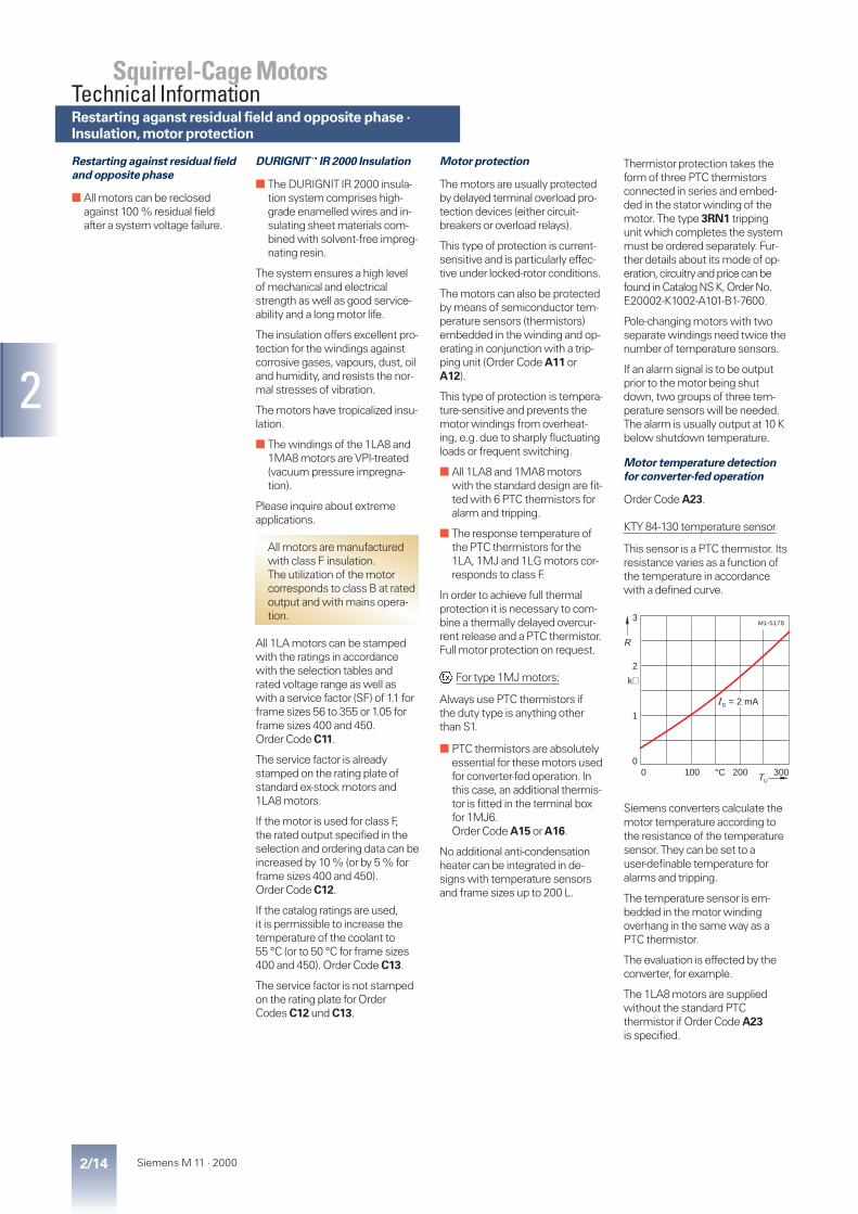
KTY 84-130 temperature sensor
This sensor is a PTC thermistor. Itsresistance varies as a function ofthe temperature in accordancewith a defined curve.
Siemens converters calculate themotor temperature according tothe resistance of the temperaturesensor. They can be set to auser-definable temperature foralarms and tripping.
The temperature sensor is em-bedded in the motor windingoverhang in the same way as aPTC thermistor.
The evaluation is effected by theconverter, for example.
The 1LA8 motors are suppliedwithout the standard PTCthermistor if Order Code A23is specified.
30020010000
1
2
3
kW
°C
M1-5178
ID = 2 mA
R
TU

Type series Frame size Framematerial
Framefeet
1LA5, 1LA7,1LA9
56 to 1001)112 to 225
Aluminium alloyAluminium alloy
castbolted
1MA7 63 to 1001)112 to 160
Aluminium alloyAluminium alloy
castbolted
1LG8 90 to 160 Cast iron cast1LA6, 1MA6 180 to 200
225 to 315 M315 L
Cast ironCast ironCast iron
boltedcastbolted
1MJ6 71 and 8090 to 160
180 to 315
Cast ironCast ironCast iron
castboltedbolted
1LA81MA8
315 to 450315 and 355
Cast ironCast iron
castcast
1MJ8 315 to 450 Welded steel welded
Mechanische Angaben �Gehäuseausführung
2/15Siemens M 11 · 2000
2
Squirrel-Cage MotorsTechnical Information
Anti-condensation heating
Order Code K45Supply voltage 230 V
Order Code K46Supply voltage 115 V
Anti-condensation heaters can befitted to motors whose windingsare exposed to a risk of condensa-tion due to the ambient climate,e.g. stationary motors in a dampenvironment or motors subjectedto considerable fluctuations intemperature.
An additional M16 x 1.5 orM20 x 1.5 cable entry fitting is pro-vided in the terminal box for thepower supply cable.
The anti-condensation heatermust not be switched on whilethe motor is running.
An alternative to anti-condensa-tion heaters (involving no extracost) is to connect a voltage ofaround 4 to 10 % of the motorrated voltage to stator terminalsU1 and V1; 20 to 30 % of themotor rated current provide anadequate heating effect.
For 1MJ6 motors:
No built-in anti-condensationheater is available for 1MJ6 mo-tors up to frame size 200 L whenequipped with PTC thermistors.
For motors Frame size Heat output (W) for Order CodeK45 (230 V) K46 (115 V)
1LA5,1LA6,1LA7,1MA6,1MJ6
56 to 8090 to 112
132 to 200225 to 250280 to 315
2550
1007898
2550
1007898
1LG8 90 and 100112 and 132160
12.52550
12.52550
1LA81MA8
allall
200140
183129
1MJ8 315355400450
100200200280
100200200280
Degrees of protection
to DIN EN 60 034-5
AllmotorsandCOMBIMASTERaredesigned for IP55.
They are suitable for use in dustyor damp surroundings.
The 1LA6 and 1MA6 fromBG 225 M as well as 1LA8 and1MA8 motors have condensationdrain holes sealed with plasticplugs.
■ All motors which have a shaftextension pointing upwardsmust have a means (providedby the user) of preventing theingress of water along theshaft.
In the case of flange-mountingmotors with IM V 3 type of con-struction, the liquid level in theflange recess can be preventedfrom rising by means of drainholes (to order). These are
standard for 1LA6, 1MA6 and1MJ6 motors with framesize 225 or larger.
No additional protection againstthe effects of the weather isnecessary for the motors, provid-ing they are stored correctly ormounted outdoors in a suitablemanner.
They must, however, be protectedagainst direct sunlight, e.g. with acanopy.
Anti-condensation heaters,degrees of protection ·frame design
Frame design
Some foot-mounting motorshave two fixing holes at thenon-drive end (see DimensionsPart 7).
There is a cast inscription nearthese holes to differentiatebetween frame sizes.
Eyebolts
The 1LA7, 1MA7 and 1LA5 mo-tors from frame size 100 L uphave two cast eyebolts with theterminal box design.
The 1LA5 motors can optionallybe fitted with two additionaleyebolts for the types of construc-tion IM V 1 and IM V 3.Order Code K32.
The 1LG8 motors from framesize 100 L on have two boltedeyebolts.
■ The 1LA6 motors and the1MA6 and 1MJ6 motors withframe size 180 M or larger haveone eyebolt with the standardIM B 3 type of construction andtwo eyebolts with the IM B 5type of construction. If the mo-tors are used with the IM V 1type of construction, one of theeyebolts must be repositioned,whereby care must be taken toavoid stress perpendicular tothe eyebolt.
The 1LA8 motors have oneeyebolt for the IM B 3 type of con-struction and two eyebolts for theIM V 1 type of construction.
1MJ6 motors, frame size 100 L to132 M have to eyebolts, framesizes 160 M to 160 L one eyebolt.
1) Frame size 100 with side-mountedterminal box has bolted feet.
Cooling and ventilation
2/16 Siemens M 11 · 2000
2
Squirrel-Cage MotorsTechnical Information
Coupling to gearboxes
The motors can be fitted with a ra-dial seal for coupling to gearboxes.Order Code K17.
There must be adequate lubrica-tion with grease, oil spray or oilmist (pressure oil is not allowed).
It is advisable to check the permit-ted bearing loads.
Please enquire about 1LA8 mo-tors.
Speed and direction of rotation
The rated speed values apply tooperation under rated conditions.The synchronous speed varies indirect proportion to the frequencyof the power supply system.
The motors are suitable for oper-ating in either direction of rotation(exceptions: 1LA8, 1MA8 and1MJ8 motors, 2-pole).
Connecting terminals U1, V1 andW1 to phases L1, L2 and L3 willresult in clockwise rotation look-ing towards the drive end of theshaft. Anticlockwise rotation canbe achieved by interchanging twoof the phases (see also “Coolingand ventilation”).
Cooling and ventilation
Standard motors with frame sizes63 to 450 (exception: 1LA8 and1MA8 motors, 2-pole) are fittedwith a radial-flow fan which func-tions independently of the direc-tion of rotation (cooling methodIC 411 to DIN EN 60 034-6).
Motors with frame size 56 haveno fan (IC 410).
■ Standard, 2-pole 1LA8 and1MA8 motors have an axial-flow fan for clockwise rotation(exception: 1LA831). It is possi-ble to convert the fan subse-quently for anticlockwise rota-tion.
If the motor is installed in an areawith a limited air supply, it is es-sential to ensure a minimum clear-ance between the fan cowl andthe wall, equal to the distancebetween the canopy and the cowl(dimension k2 – k).
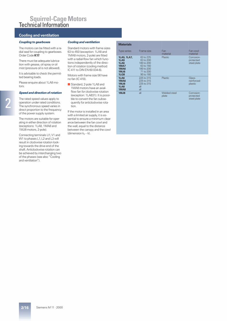
Materials
Type series Frame size Fanmaterial
Fan cowlmaterial
1LA5, 1LA7,1LA91LA61MA71MA61MJ61LG8
63 to 22563 to 200
180 to 20063 to 160
180 to 20071 to 20090 to 160
Plastic Corrosion-protectedsteel plate
1LA61MA61MJ61LA81MA8
225 to 315225 to 315225 to 315allall
Plastic Glass-reinforcedplastic
1MJ8 all Welded steelplate
Corrosion-protectedsteel plate

Noise (direct on-line operation)
2/17Siemens M 11 · 2000
2
Squirrel-Cage MotorsTechnical Information
The noise levels are measured inaccordance with EN 21 680-1 in adead room with rated power.
LpfA is specified in dB as theA-weighted measuring-surfacesound pressure level.
This value is the spatial mainvalue of the sound pressure levelsmeasured on the test hemi-sphere. This hemisphere is acuboid at a distance of 1 m fromthe machine surface. The soundpower level LWA is specified in dB.
The values are applicable at 50 Hzwith a tolerance of +3 dB. Theyare approximately 4 dB higher at60 Hz.
Please enquire about the noiselevels for pole-changing motors,motors with an increased poweroutput or motors for converter-fedoperation.
A-weighted measuring-surfacesound pressure level and soundpower
Standard design
Type series Framesize
Measuring-surface sound pressure level (LpfA)Sound power level (LWA)2-poleLpfA LWA
4-poleLpfA LWA
6-poleLpfA LWA
8-poleLpfA LWA
dB dB dB dB dB dB dB dB1LA5, 1LA6, 1LA7,1LA9,1MA7, 1MA6,1MJ6
566371
414952
526063
424244
535355
383939
495050
––
36
––
478090
100
566062
677274
474853
586065
404347
515559
414145
525357
112132160
636870
758082
536266
657478
526366
647578
495363
616575
180200225
707171
838484
636565
767878
666659
787872
605858
737171
250280315
757779
899193
656769
798183
606063
747477
575862
717276
1LG8 90100112
606464
727676
495454
606666
475054
586266
464953
576165
132160
6368
7580
5964
7176
6063
7275
5561
6773
1LA8, 1MA8 315355400450
821)771)791)811)
97929496
73757881
87909396
68717375
82868890
65676971
79828486
1MJ8 315355
8082
9497
7073
8488
7075
8490
6973
8388
400450
8284
9799
7980
9495
8083
9588
7478
8993
In order to reduce noise levels,2-pole motors with frame sizes132 S or larger can be fitted withan axial-flow fan that is suitablefor one direction of rotation only.
Clockwise rotationOrder Code K37
Anticlockwise rotationOrder Code K38
Low-noise design
Type series Framesize
2-pole motorsLpfA LWA
dB dB
1LA5, 1LA6, 1LA7,1MA7, 1MA6,1MJ6
132160
6464
7676
180200
6363
7676
225250
6870
8082
280315
7274
8486
1LG8 132160
5657
6869
1LA8 315 75 901MJ8 315
355400
6869o. r.
8284o. r.
The motors up to frame size 315 Lare 80 mm longer than normal.A second shaft extension and/orpulse generator mounting is notpossible.
1) The standard 1LA8 and1MA8 design, 2-pole have anaxial-flow fan for clockwiserotation (exception: 1LA8 31.).Order Code K37 is notneeded.For anticlockwise rotationplease state Order Code K38.
Terminal boxes
2/18 Siemens M 11 · 2000
2
Squirrel-Cage MotorsTechnical Information
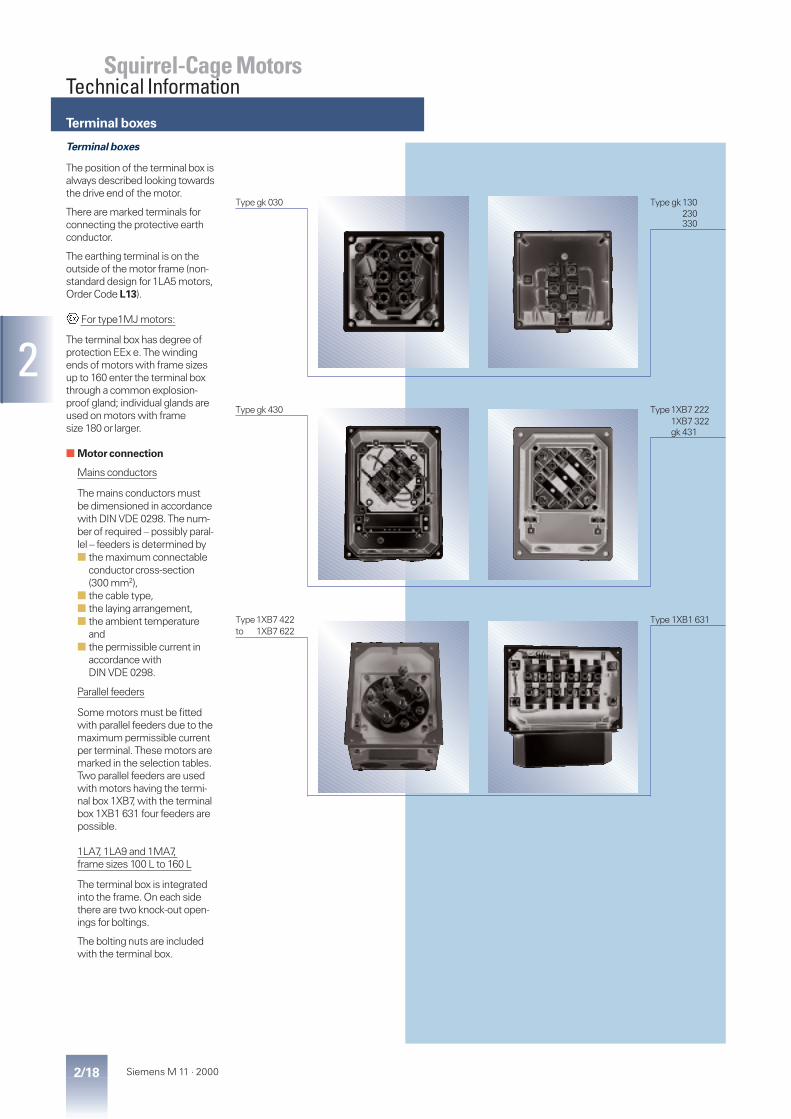
Terminal boxes
The position of the terminal box isalways described looking towardsthe drive end of the motor.
There are marked terminals forconnecting the protective earthconductor.
The earthing terminal is on theoutside of the motor frame (non-standard design for 1LA5 motors,Order Code L13).
For type1MJ motors:
The terminal box has degree ofprotection EEx e. The windingends of motors with frame sizesup to 160 enter the terminal boxthrough a common explosion-proof gland; individual glands areused on motors with framesize 180 or larger.
■ Motor connection
Mains conductors
The mains conductors mustbe dimensioned in accordancewith DIN VDE 0298. The num-ber of required – possibly paral-lel – feeders is determined by■ the maximum connectable
conductor cross-section(300 mm2),
■ the cable type,■ the laying arrangement,■ the ambient temperature
and■ the permissible current in
accordance withDIN VDE 0298.
Parallel feeders
Some motors must be fittedwith parallel feeders due to themaximum permissible currentper terminal. These motors aremarked in the selection tables.Two parallel feeders are usedwith motors having the termi-nal box 1XB7, with the terminalbox 1XB1 631 four feeders arepossible.
1LA7, 1LA9 and 1MA7,frame sizes 100 L to 160 L
The terminal box is integratedinto the frame. On each sidethere are two knock-out open-ings for boltings.
The bolting nuts are includedwith the terminal box.
Type gk 030 Type gk130230330
Type gk 430 Type1XB7 2221XB7 322gk 431
Type1XB7 422 Type 1XB1 631to 1XB7 622
Terminal boxes
2/19Siemens M 11 · 2000
2
Squirrel-Cage MotorsTechnical Information
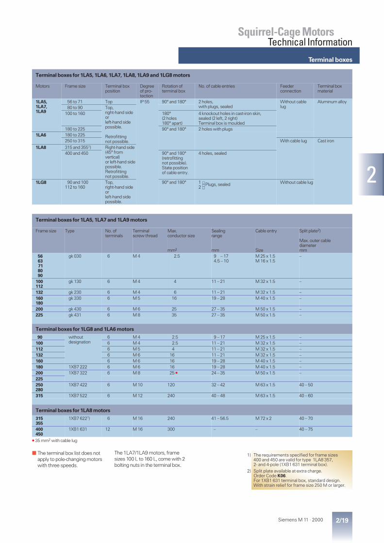
Terminal boxes for 1LA5, 1LA6, 1LA7, 1LA8, 1LA9 and 1LG8 motors
Motors Frame size Terminal boxposition
Degreeof pro-tection
Rotation ofterminal box
No. of cable entries Feederconnection
Terminal boxmaterial
1LA5,1LA7,1LA9
56 to 71 Top IP 55 90° and 180° 2 holes,with plugs, sealed
Without cablelug
Aluminum alloy80 to 90 Top,
right-hand sideorleft-hand sidepossible.
Retrofittingnot possible.
100 to 160 180°(2 holes180° apart)
4 knockout holes in cast-iron skin,sealed (2 left, 2 right)Terminal box is moulded
180 to 225 90° and 180° 2 holes with plugs1LA6 180 to 225
250 to 315 With cable lug Cast iron
1LA8 315 and 3551) Right-hand side(45° fromvertical)or left-hand sidepossible.Retrofittingnot possible.
400 and 450 90° and 180°(retrofittingnot possible).State positionof cable entry.
4 holes, sealed
1LG8 90 and 100112 to 160
Top,right-hand sideorleft-hand sidepossible.
90° and 180° 1 Plugs, sealed2
Without cable lug
Terminal boxes for 1LA5, 1LA7 and 1LA9 motors
Frame size Type No. ofterminals
Terminalscrew thread
Max.conductor size
mm2
Sealingrange
mm
Cable entry
Size
Split plate2)
Max. outer cablediametermm
5663718090
gk 030 6 M 4 2.5 9 – 174.5 – 10
M 25 x 1.5M 16 x 1.5
–
100112
gk 130 6 M 4 4 11 – 21 M 32 x 1.5 –
132 gk 230 6 M 4 6 11 – 21 M 32 x 1.5 –160180
gk 330 6 M 5 16 19 – 28 M 40 x 1.5 –
200 gk 430 6 M 6 25 27 – 35 M 50 x 1.5 –225 gk 431 6 M 8 35 27 – 35 M 50 x 1.5 –
Terminal boxes for 1LG8 and 1LA6 motors
90 withoutdesignation
6 M 4 2.5 9 – 17 M 25 x 1.5 –100 6 M 4 2.5 11 – 21 M 32 x 1.5 –112 6 M 5 4 11 – 21 M 32 x 1.5 –132 6 M 6 16 11 – 21 M 32 x 1.5 –160 6 M 6 16 19 – 28 M 40 x 1.5 –180 1XB7 222 6 M 6 16 19 – 28 M 40 x 1.5 –200 1XB7 322 6 M 8 25 V 24 – 35 M 50 x 1.5 –225250280
1XB7 422 6 M 10 120 32 – 42 M 63 x 1.5 40 – 50
315 1XB7 522 6 M 12 240 40 – 48 M 63 x 1.5 40 – 60
Terminal boxes for 1LA8 motors
315355
1XB7 6221) 6 M 16 240 41 – 56.5 M 72 x 2 40 – 70
400450
1XB1 631 12 M 16 300 – – 40 – 75
V 35 mm2 with cable lug
■ The terminal box list does notapply to pole-changing motorswith three speeds.
1) The requirements specified for frame sizes400 and 450 are valid for type 1LA8 357,2- and 4-pole (1XB1 631 terminal box).
2) Split plate available at extra charge.Order Code K06.For 1XB1 631 terminal box, standard design.With strain relief for frame size 250 M or larger.
The 1LA7/1LA9 motors, framesizes 100 L to 160 L, come with 2bolting nuts in the terminal box.

Terminal boxes
2/20 Siemens M 11 · 2000
2
Squirrel-Cage MotorsTechnical Information
Terminal boxes for 1MA7, 1MA6 and 1MA8 motors
Frame size Type No. ofterminals
Terminalscrew thread
Max.conductor size
mm2
Sealingrange
mm
Cable entry
Size
Split plate2)
Max. outer cablediametermm
63 gk 130 6 M 4 4 11 – 165 – 9
M 25 x 1.5M 16 x 1.5
–718090
100 14 – 21 M 32 x 1.5 –112132 gk 230 6 M 4 6160 gk 330 6 M 5 16 19 – 27 M 40 x 1.5 –180 1XB7 222 6 M 6 10 19 – 27 M 40 x 1.5 –200225
1XB7 322 6 M 8 50 24 – 35 M 50 x 1.5 –
250280
1XB7 422 6 M 10 120 32 – 42 M 63 x 1.5 40 – 50
315 1XB7 522 6 M 12 240 40 – 48 M 63 x 1.5 40 – 60
Terminal boxes for 1MA8 motors
315355
1XB7 622 6 M 16 240 41 – 56.5 M 72 x 2 –
3552) 1XB1 631 12 M 16 240 – – 40 – 75
■ Unused holes for 1MA and1ME motors must be sealed inaccordance with EN 50 014.
Terminal boxes for 1MA7, 1MA6 and 1MA8 motors
Motors Frame size Terminal boxposition
Degreeof pro-tection
Rotation ofterminal box
No. of cable entries Feederconnection
Terminal boxmaterial
1MA7 63 to 71 Top IP 55 90° and 180° 2 holes,1 gland with sealing ring,1 plug
Without cablelug1)
Aluminum alloy80 to 90 Top,
right-hand sideorleft-hand sidepossible.
Retrofittingnot possible.
100 to 160180° (2 holes180° apart)
4 knockout holes in cast-iron skin, sealed(2 left, 2 right)Terminal box is moulded
1MA6 180 to 225 90° and 180° 2 boltings with sealing ring250 to 315 Cast iron
1MA8 315 and 355 Right-hand side(45° fromvertical),left-hand sidepossible.
Retrofittingnot possible.
3552) 90° and 180°(retrofittingnot possible).State positionof cable entry.
4 holes, sealed
1) The parts required for the connec-tion without cable lugs are suppliedin an accessories pack with theterminal box for all motors withframe size 225 or larger.
2) Requirements only valid for1MA8 357, 2- and 4-pole.
The 1MA7 motors, frame sizes100 L to 160 L, come with 1 bolt-ing with sealing ring and two bolt-ing nuts in the terminal box.
Terminal boxes
2/21Siemens M 11 · 2000
2
Squirrel-Cage MotorsTechnical Information
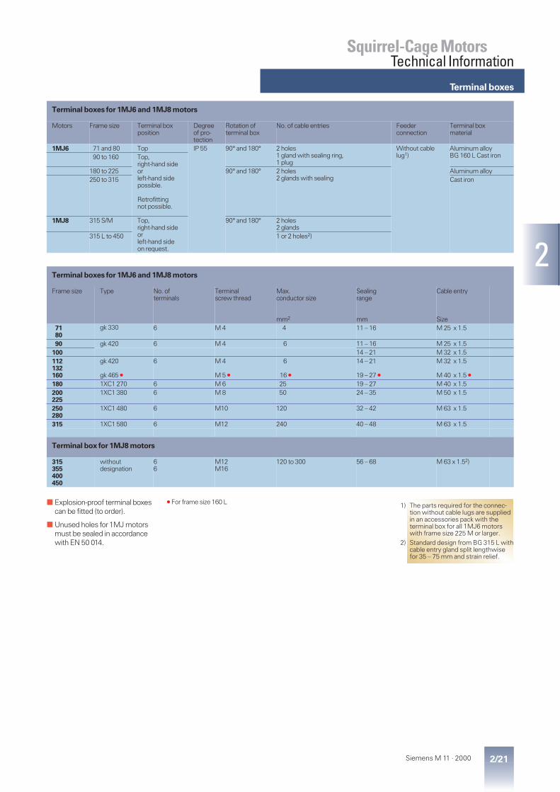
Terminal boxes for 1MJ6 and 1MJ8 motors
Frame size Type No. ofterminals
Terminalscrew thread
Max.conductor size
mm2
Sealingrange
mm
Cable entry
Size7180
gk 330 6 M 4 4 11 – 16 M 25 x 1.5
90 gk 420 6 M 4 6 11 – 16 M 25 x 1.5100 14 – 21 M 32 x 1.5112132160
gk 420
gk 465 V
6 M 4
M 5 V
6
16 V
14 – 21
19 – 27 V
M 32 x 1.5
M 40 x 1.5 V
180 1XC1 270 6 M 6 25 19 – 27 M 40 x 1.5200225
1XC1 380 6 M 8 50 24 – 35 M 50 x 1.5
250280
1XC1 480 6 M10 120 32 – 42 M 63 x 1.5
315 1XC1 580 6 M12 240 40 – 48 M 63 x 1.5
Terminal box for 1MJ8 motors
315355400450
withoutdesignation
66
M12M16
120 to 300 56 – 68 M 63 x 1.52)
■ Explosion-proof terminal boxescan be fitted (to order).
■ Unused holes for 1MJ motorsmust be sealed in accordancewith EN 50 014.
Terminal boxes for 1MJ6 and 1MJ8 motors
Motors Frame size Terminal boxposition
Degreeof pro-tection
Rotation ofterminal box
No. of cable entries Feederconnection
Terminal boxmaterial
1MJ6 71 and 80 Top IP 55 90° and 180° 2 holes1 gland with sealing ring,1 plug
Without cablelug1)
Aluminum alloyBG 160 L Cast iron90 to 160 Top,
right-hand sideorleft-hand sidepossible.
Retrofittingnot possible.
180 to 225 90° and 180° 2 holes2 glands with sealing
Aluminum alloy250 to 315 Cast iron
1MJ8 315 S/M Top,right-hand sideorleft-hand sideon request.
90° and 180° 2 holes2 glands
315 L to 450 1 or 2 holes2)
1) The parts required for the connec-tion without cable lugs are suppliedin an accessories pack with theterminal box for all 1MJ6 motorswith frame size 225 M or larger.
2) Standard design from BG 315 L withcable entry gland split lengthwisefor 35 – 75 mm and strain relief.
V For frame size 160 L

Types of construction
2/22 Siemens M 11 · 2000
2
Squirrel-Cage MotorsTechnical Information
Type of construction to DIN EN 60 034-7 Frame size Code Order Code12th position
IM B 356 M to 450 04) –
IM B 6, IM B 7, IM B 856 M to 315 L 0 –
IM V 5 without canopy56 M to 315 M315 L
091)
–M1D
IM V 656 M to 315 M315 L
091)
–M1E
IM V 5 with canopy63 M to 315 L 91) M1F
Flange
IM B 556 M to 315 M 12) –
IM V 1 without canopy56 M to 315 M315 L to 450
12)3)84)5)
––
IM V 1 with canopy63 M to 450 41)2)3)5) –
IM V 356 M to 160 L180 M to 315 M
192)3)
–M1G
IM B 35 6)56 M to 450 64) –
The flanges are assigned to the frame sizes as FF with through-holes in DIN EN 50 347.A-flanges acc. to DIN 42 948 are still valid.
1) 60 Hz is available for 2-pole motorswith frame size 315 L on request.
2) Motors with frame sizes between225 S and 315 M are delivered withtwo eyebolts according to IM B 5,one of which may be repositionedacc. to IM V 1 or IM V 3; then, caremust be taken to avoid stress per-pendicular to the eyebolt.
3) With frame sizes between 180 Mand 225 M, the motors are available
with two additional eyebolts; pleasestate order suffix “Z“ and OrderCode K32.
4) Frame size 450, 2-pole, 60 Hznot available.
5) 60 Hz design is not available for2-pole 1LA8 motors with frame size355 or larger.
6) With 1LA8, the related flangediameter is greater than doublethe shaft height.

Types of construction
2/23Siemens M 11 · 2000
2
Squirrel-Cage MotorsTechnical Information
Type of construction to DIN EN 60 034-7 Frame size Code Order Code12th position
Standard flange
IM B 14, IM V 19,IM V 18 without canopy 56 M to 160 L 2 –
IM V 18 with canopy63 M to 160 L 9 M2A
IM B 3456 M to 160 L 7 –
Custom flange
IM B 14, IM V 19,IM V 18 without canopy 56 M to 160 L 3 –
IM V 18 with canopy63 M to 160 L 9 M2B
IM B 3456 M to 160 L 9 M2C
The standard flanges are assigned to the frame sizes as FT with threaded holes in DIN 50 347.C-flanges acc. to DIN 42 948 are still valid.The custom flange was assigned as large flange in the previous DIN 42 677.
All types of construction within the following series have equal dimensions:IM B 3, IM B 6, IM B 7 , IM B 8, IM V 5 and IM V 6IM B 5, IM V 1 and IM V 3IM B 14, IM V 18 and IM V 19
The motors in the standard power range are available in the standard types of construction IM B 3, IM B 5 or IM B 14, and can be operated in themounting positions IM B 6, IM B 7, IM B 8, IM V 5, IM V 6, IM V 1, IM V 3 (up to frame size 160 L) or IM V 18 and IM V 19 (universal type ofconstruction).
■ On the normal rating plate, therefore, they are marked with only the basic type of construction.■ If foot-type motors larger than frame size 180 M are mounted to the wall, it is recommended that especially the motor feet are supported.
For all motors with the shaft end pointing down,the version “with canopy“ is recommended;see chapter “degrees of protection“, page 2/15.
For explosion-proof motors:For types of construction with shaft end pointingdown, the version “with canopy“is mandatory.Types of construction with shaft end pointing upmust be suitably covered in order to avoid thatsmall parts fall into the fan cowl.(See also section 17 DIN EN 50 014.)The cooling may not be impaired by the cover.
Bearings
2/24 Siemens M 11 · 2000
2
Squirrel-Cage MotorsTechnical Information
Bearings
The nominal bearing life of motorswith horizontal type of construc-tion is at least 40,000 hours ifthere is no additional axial loadingat the output coupling; with themaximum permitted loads listedon pages 2/29 to 2/35 it is at least20,000 hours, provided themotor is operated at 50 Hz.
The bearings of motors withframe sizes up to 250 M are pre-lubricated. Frame size 280 S andlarger sizes are regreasable with aflat-type grease nipple M 10 x 1 inaccordance with DIN 3404.
Regreasable bearings can befitted in motors with frame sizes100 L to 250 M.Order Code K40 (extra charge)
The bearings must be regreasedat regular intervals according tothe pot life of the grease, in orderto ensure that they achieve theirnominal service life.
The stated grease pot life appliesto the standard bearing design.Please enquire if the bearing issubjected to increased cantileverforces.
The 1LA7 motors up to frame size132 M do not have a locatingbearing.
The bearings at the drive end arepreloaded.
Frame sizes 160 M to 315 L, all1MJ6 motors, and 1LG8 motorswith frame size 112 M or largerhave a locating bearing at thenon-drive end and a floating bear-ing at the drive end; the latter is apreloaded, deep-groove ball bear-ing. Motors equipped with parallelroller bearings are an exception tothis rule (see pages 2/25 to 2/28for selection of bearings).
The standard 1LA8 motors havethe fixed bearing at the drive end.Vertically mounted motors andmotors for high cantilever forceshave this bearing at the non-driveend.
If high cantilever forces areexerted at the drive end, e.g.owing to a belt transmission, themotors can be fitted with otherbearings on request at an extracharge (please inquire about1LG8, 1MJ6 with frame sizes be-tween 280 and 315, and 1MJ8motors; not available for 1MJ6 upto frame size 160 L.Order Code K20 (see page 2/30for selection of bearings.)
If bearings for high cantileverforces are fitted, the followingmust be noted: the minimum per-mitted cantilever force is equal tothe maximum permitted force forthe standard bearings (vibrationseverity grades R and S are notpossible).
With various motors, a locatingbearing with a retaining ring canbe fitted at the non-drive end onrequest (Order Code L04, Fig. 2,Page 2/27).Alternatively, a locating bearingwith a stationary outer race heldby an inner bearing cover can befitted at the drive end (Order CodeK94, Fig. 3, Page 2/27).
Mechanical limit speeds for
converter-fed 1LA8 motors see
page 3/21.
Type of lubrication Frame size No. of poles Grease life and/or relubrication intervalat KT 40 °C at KT 25 °C
Prelubricated Up to 250 24 to 8
10 000 h20 000 h
20 000 h40 000 h
Regreasable 280 and 315 24 to 8
2 000 h4 000 h
4 000 h8 000 h
355 to 450 2 and 46 and 8
2 000 h4 000 h
4 000 h8 000 h

2/25Siemens M 11 · 2000
2
Squirrel-Cage MotorsTechnical Information
Selection of bearings
Selection of bearings for 1LA, 1MA and 1LG motors, basic design
For motorsFrame size
Type1LA5 . . .1LA6 . . .1LA7 . . .1LA9 . . .1MA6 . . .1MA7 . . .
No. of poles Drive-end bearing Non-drive endbearing
Fig. No.onpages2/27 and2/28
Horizontalmotors
Verticalmotors
Horizontalmotors
Verticalmotors
56 1LA7 05 . all 6201 2ZC3 6201 2ZC3 Fig. 163 . . . . 06 . all 6201 2ZC3 6201 2ZC371 . . . . 07 . all 6202 2ZC3 6202 2ZC380 . . . . 08 . all 6004 2ZC3 6004 2ZC390 . . . . 09 . all 6205 2ZC3 6004 2ZC3
100 . . . . 10 . all 6206 2ZC31) 6205 2ZC31)112 . . . . 113 all 6206 2ZC31) 6205 2ZC31)132 . . . . 13 . all 6208 2ZC31) 6208 2ZC31)160 . . . . 16 . all 6209 2ZC31) 6209 2ZC31) Fig. 2180 . . . . 18 . all 6210 ZC31) 6210 ZC31) Fig. 4200 . . . . 20 . all 6212 ZC31) 6212 ZC31)225 . . . . 22 . all 6213 ZC31) 6212 ZC31)250 . . . . 253 all 6215 ZC31) 6215 ZC31)280280
. . . . 28 . 24 to 8
6216 C36317 C3
6216 C36317 C3
Fig. 5
315 S315 M
. . . . 310
. . . . 31324 to 8
6217 C36319 C3
6217 C36319 C3
315 L . . . . 316. . . . 317. . . . 318
24 to 8
6217 C36319 C3
6217 C32)6319 C3
6217 C36319 C3
7217 B2)6319 C3
1LG8 . . .1LA6 . . .
90 1LG8 09 . all 6205 2Z C3 6205 2Z C3 Fig. 6100 1LG8 10 . all 6206 2Z C3 6205 2Z C3112 1LG8 11 . all 6306 2Z C3 6206 2Z C3132 1LG8 13 . all 6308 2Z C3 6208 2Z C3160 1LG8 16 . all 6309 2Z C3 6210 2Z C3180 1LA6 18 . 6210 Z C3 6210 Z C3 Fig. 4200 1LA6 20 . 6212 Z C3 6212 Z C3225 1LA6 22 . 6213 Z C3 6213 Z C3
1LA8 . . .1MA8 . . .
315 . . . . 31 . 24 to 8
NU 215 E + 6215 C3NU 218 E + 6218 C3
6215 C36218 C3
NU 215 ENU 218 E
7215 B7218 B
Fig. 7a
355 . . . . 35 . 24 to 8
NU 217 E + 6217 C3NU 220 E + 6220 C3
6217 C32)6220 C3
NU 217 ENU 220 E
7217 B2)7220 B
400 1LA8 40 . 24 to 8
NU 217 E + 6217 C3NU 224 E + 6224 C3
6217 C32)6224 C3
NU 217 ENU 224 E
7217 B2)7224 B
450 1LA8 45 . 24 to 8
NU 219 E + 6219 C32)NU 226 E + 6226 C3
6219 C32)6226 C3
NU 219 E2)NU 226 E
7218 B2)7226 B
1) Bearings without sideplates areused when a regreasing device isfitted.
2) For 50 Hz only.
The bearing selection tables areonly intended for planning pur-poses. Authoritative informationon the actual type of bearingsfitted in motors already suppliedcan be obtained from the factoryby quoting the serial number orread off on the lubrication instruc-tion plate of 1LA8 motors.
When deep-groove ball bearingswith sideplates are used, thesideplate is on the inside.
Fig. 3 (page 2/27) shows thenon-standard design with a locat-ing bearing at the drive end for1LA7, 1LA9 and 1MA7 motors.
andFig. 7b

Selection of bearings
2/26 Siemens M 11 · 2000
2
Squirrel-Cage MotorsTechnical Information
Selection of bearings for 1MJ motors, basic design
For motorsFrame size
Type No. of poles Drive-end bearing Non-drive endbearing
Fig. No.on page2/31Horizontal motors and
vertical motorsHorizontalmotor
Verticalmotor
71 1MJ6 07. all 6202 ZC3 6202 ZC3 Fig. 880 1MJ6 08 . all 6004 ZC3 6004 ZC390 L 1MJ6 09 . all 6205 C3 6205 C3 Fig. 9
100 L 1MJ6 10 . all 6206 C3 6206 C3112 M 1MJ6 11. all 6306 C3 6306 C3132 S132 M
1MJ6 13 . all 6308 C3 6308 C3 Fig. 10
160 M160 L
1MJ6 16 . all 6309 C3 6309 C3
180 M180 L
1MJ6 18 . all 6210 C3 6210 C3 Fig. 11
200 L 1MJ 6 20 . all 6212 C3 6212 C3225 S225 M
1MJ6 22 . all 6213 C3 6213 C3
250 M 1MJ6 253 all 6215 C3 6215 C3280 S280 M
1MJ6 28 . all NU 216 6216 C3 Fig. 12
315 S315 M
1MJ6 31 . 24 to 8
NU 217NU 218
6217 C36218 C3
315 1MJ8 31 . 24 to 8
6316 C36320 C3
6316 C36320 C3
6316 C36320 C3
Fig. 13
355 1MJ8 35 . 24 to 8
6316 C36320 C3
6316 C36320 C3
6316 C36320 C3
400 1MJ8 40 . 24 to 8
6317 C46322 C4
6317 C46322 C4
7317 BM7322 BMP
450 1MJ8 45 . 24 to 8
6317 C46322 C4
6317 C46322 C4
71317 BM7322 BMP
The bearing selection tables areonly intended for planning pur-poses. Authoritative informationon the actual type of bearingsfitted in motors already suppliedcan be obtained from the factoryby quoting the serial number.
When deep-groove ball bearingswith sideplates are used, thesideplate is on the inside.
1MJ8 motors for 60 Hz onrequest.
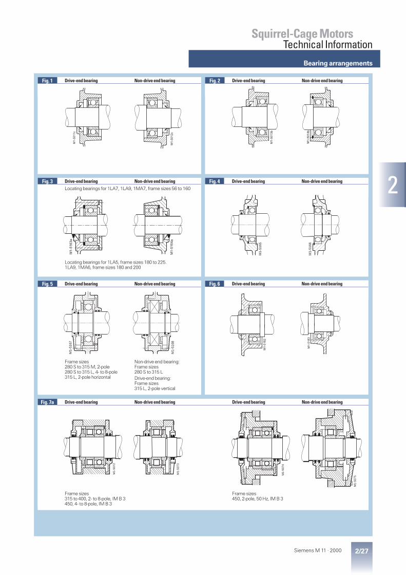
Bearing arrangements
2/27Siemens M 11 · 2000
2
Squirrel-Cage MotorsTechnical Information
Fig. 1 Drive-end bearing Non-drive end bearing Fig. 2 Drive-end bearing Non-drive end bearing
Fig. 3 Drive-end bearing Non-drive end bearingLocating bearings for 1LA7, 1LA9, 1MA7, frame sizes 56 to 160
Locating bearings for 1LA5, frame sizes 180 to 225.1LA9, 1MA6, frame sizes 180 and 200
Fig. 4 Drive-end bearing Non-drive end bearing
Fig. 5 Drive-end bearing Non-drive end bearing
Frame sizes280 S to 315 M, 2-pole280 S to 315 L, 4- to 8-pole315 L, 2-pole horizontal
Non-drive end bearing:Frame sizes280 S to 315 LDrive-end bearing:Frame sizes315 L, 2-pole vertical
Fig. 7a Drive-end bearing Non-drive end bearing Drive-end bearing Non-drive end bearing
Frame sizes315 to 400, 2- to 8-pole, IM B 3450, 4- to 8-pole, IM B 3
Frame sizes450, 2-pole, 50 Hz, IM B 3
M1-5
01
1c
M1-5
01
2c
M1-
5075
M1-
5074
M1-
5073
M1-
5072
M1-
5168
M1-
5167
M1-
5164
a
M1-
5163
a
M1-
5166
M1-
5165
M1-5
01
4b
M1-5
01
3b
Fig. 6 Drive-end bearing Non-drive end bearing
M1-5
18
3
M1-5
18
2

Bearing arrangements
2/28 Siemens M 11 · 2000
2
Squirrel-Cage MotorsTechnical Information
Fig. 7b Drive-end bearing Non-drive end bearing Non-drive end bearing
Frame sizes315, 2- to 8-pole, IM V 1355 and 450, 2- to 8-pole, 50 Hz, IM V 1
Frame sizes315, 2- to 8-pole, IM V 1355 and 400, 2- to 8-pole, 50 Hz, IM V 1450, 4- to 8-pole, 50 Hz, IM V 1
Frame size450, 2-pole, 50 Hz, IM V 1
Fig. 8 Drive-end bearing Non-drive end bearing Fig. 9 Drive-end bearing Non-drive end bearing
Fig. 10 Drive-end bearing Non-drive end bearing
Fig. 12 Drive-end bearing Non-drive end bearing Fig. 13 Drive-end bearing Non-drive end bearing
Drive and non-drive end bearing:Frame size 315 or largerOuter bearing sealFrame sizes 400 and 450with labyrinth gland
M1-5076
M1-5078
M1-5077M
1-50
91
M1-
5092
M1-
5169
M1-
5171
M1-
5170
M1-
5172
M1-
5098
M1-5
09
9a
M1-
5089
M1-
5090
M1-5101M1-5100
Fig. 11 Drive-end bearing Non-drive end bearing
M1-5101M1-5100

Maximum cantilever forces
2/29Siemens M 11 · 2000
2
Squirrel-Cage MotorsTechnical Information
The values for the maximumpermitted cantilever force FQ (N)with a radial load are based on theassumption that the line of force(i.e. the centreline of the pulley)is still within the free shaft exten-sion (dimension x).
Dimension x (mm) is the distancefrom the shoulder of the shaft tothe line of action of the force FQ.The dimension xmax. is thus thelength of the shaft extension.
Total cantilever force FQ = c · Fu
The pretensioning factor c is anempirical value determined bythe belt manufacturer. It can beapproximated as follows:
for normal flat leather belts withan idler pulley c = 2;for V-belts c = 2 to 2.5;for special synthetic belts(depending on the type and load)c = 2 to 2.5.
The peripheral force Fu (N) canbe calculated from the followingequation
FP
n Du = ⋅⋅
2 107
Fu Peripheral force in NP Motor rated output
(transmitted power) in kWn Motor rated speed in rpmD belt pulley diameter in mm
Standard belt pulleys conformingto DIN 2211, Sheet 3, are used.
Reduced values for 60 Hz onrequest.
Maximum cantilever forcesfor 50 Hzbasic version
x0 values refer to x = 0 and xmax. values to x = l
For motors Max. cantileverforce at x0
Max. cantileverforce at xmax.
No. ofpoles
Type1LA51LA71LA91MA61MA7
1LG81LA6
1MJ6Type1LA51LA71LA91MA61MA7
1LG81ME8
1MJ61LA6
N N N N N N56 2
46
270350415
–––
–––
240305360
–––
–––
63 246
270350415
–––
–––
240305360
–––
–––
71 2468
415530630690
––––
415530630
–
355450535585
––––
355450535
–80 2
468
485625735815
––––
485625735
–
400515605675
––––
400515605675
90 S90 L
2468
725920
10901230
770970
11201240
725920
10901230
605775910
1030
620780900990
605775910
1030100 L 2
468
1030131015501720
1100145016501820
1030131015501720
840106012501400
950800800800
840106012501400
112 M 2468
1010127015201690
1600210024002650
1680196021402450
830104012401380
1350150015201540
1490158017201950
132 S132 M
2468
1490194022602500
2350300035003800
2250272031003400
1180153017801980
1900250028502850
1820217024202700
160 M160 L
2468
1540204023302660
2900370042504700
2800333037503750
1210159018202080
2300270027003000
2250260029002900
180 M180 L
2468
2000235028003050
2000235028003050
2000235028003050
1550195022502500
1550195022502500
1550195022502500
200 L 2468
2550335039004150
2550335039004150
2550335039004150
2100275032003450
2100275032003450
2100275032003450
225 S225 M
2468
3050375045504850
3050375045504850
3050375045504850
2550295036003900
2550295036003900
2550295036003900
Maximum cantilever forcesfor 50 Hzbasic version
x0 values refer to = 0 and xmax. values to x = l
For motors Max. cantileverforce at x0
Max. cantileverforce at xmax.
Framesize
.
No. ofpoles
Type1LA61MA6
1MJ6Type1LA61MA6
1MJ6
N N N N250 M 2
468
3650440053505700
3650440053505700
2950360043504700
2950360043504700
280 S280 M
2468
33508400
1000011000
8100720085009500
2800720089009850
670080509700
10600315 S315 M
2468
39509900
1210013300
9000131001560016900
335081009900
10900
7600108001280013900
315 L 2468
31008800
1140012500
18400225002520027700
270074509600
10500
15600186002110023100
1LA81MA8
1MJ8 1LA81MA8
1MJ8
315 2468
8650154001720019000
seediagramspage 2/31
7600132001470014300
seediagramspage 2/31
355 2468
10600212002340025700
seediagramspage 2/31
9500186001840016300
seediagramspage 2/31
400 2468
9800284003120034500
seediagramspage 2/31
8700243002700027600
seediagramspage 2/31
450 2468
13500292003250036100
seediagramspage 2/31
12100255003130031300
seediagramspage 2/31
Please note that in the case of the IM B 6, IM B 7,IM B 8, IM V 5 and IM V 6 types of construction, thebelt tension is only allowed to act parallel to ortowards the mounting plane and that the feet mustbe braced.
Refer to pages 2/30 and 2/31 if the cantilever forcesare higher than those listed above.
FQ
M1-5180
x
Maximum cantilever forces,basic design

Maximum cantilever forces
2/30 Siemens M 11 · 2000
2
Squirrel-Cage MotorsTechnical Information
Maximum cantilever forcesfor 50 Hz for type 1LA, 1MA and 1MJ motorsBearings for high cantilever forces
For motors Max. cantilever force at FQ
Framesize
Type1LA5 . . .1LA61LA7 . . .1LA9 . . .1MA6 . . .1MA71MJ6 . . .
No. of poles atx0
atxmax.
N N100 . . . . 10 . 2
468
1680196021402450
1490158017201950
112 . . . . 113 2468
1680196021402450
1490158017201950
132 . . . . 13 . 2468
2250272031003400
1820217024202700
160 . . . . 16 . 2468
2800333037503750
2250260029002900
180 . . . . 18 . 2468
3700445051005550
3000360041504500
200 . . . . 20 . 2468
5200645073007900
4300535061006550
Maximum cantilever forcesfor 50 Hz for type 1LA, 1MA and 1MJ motorsBearings for high cantilever forces
For motors Max. cantilever force at FQ
Framesize
Type1LA5 . . .1LA6 . . .1MA6 . . .1MJ6 . . .
No. of poles atx0
atxmax.
N N225 . . . . 22 . 2
468
81009800
1120012200
6800780088009700
250 . . . . 25 . 2468
9600116001320014400
79009600
1080011800
280 . . . . 28 . 2 10000 8400315 S315 M
. . . . 310
. . . . 3132 12000 10200
315 L . . . . 316 2 11800 10200. . . . 317 (horizontal motors)
Please note that in the case of IM B 6, IM B 7,IM B 8, IM V 5 and IM V 6 types of construction, thebelt extension is only allowed to act parallel to or to-wards the mounting plane and that the feet must bebraced.
Selection of bearings for 1LA, 1MA and 1MJ motorsBearings for high cantilever forces · Order Code K20
For type 1LG8, 1MJ6 motors, frame sizes 280 to 315 and for type 1MJ8 motorson request, not available for 1MJ6 up to frame size 160
For motor Drive-end bearingFrame size Type
1LA5 . . .1LA6 . . .1LA7 . . .1LA9 . . .1MA6 . . .1MA71MJ6 . . .
No. of poles Horizontalmotors
Verticalmotors
100 . . . . 10 . all 6306 ZC3112 . . . . 11 . all 6306 ZC3132 . . . . 13 . all 6308 ZC3160 . . . . 16 . all 6309 ZC3180 . . . . 18 . all 6310 Z C3 (NU 210)2)
200 . . . . 20 . all 6312 ZC3 (NU 212)2)
225 . . . . 22 . all NU 213 E3)250 . . . . 253 all NU 215 E3)280 . . . . 28 . 2
4 to 8NU 216 E3)NU 317 E3)
315 S315 M
. . . . 310
. . . . 31324 to 8
NU 217 E3)NU 319 E3)
315 L . . . . 316. . . . 317. . . . 318
24 to 8
NU 217 E3)NU 319 E3)
–NU 319 E1)
1LA8 . . .1MA8 . . .
315 . . . . 31 . 4 to 8 NU 320 E on request355 . . . . 35 . 4 to 8 NU 322 E on request
Minimum cantilever force required
FQ
M1-5180
x
Noise and vibration dataavailable on request.
The non-drive end bearing equals thebasic design.
1) For 50 Hz only.2) Bracketed data for 1MJ6 motors3) Also deep-groove bearings of the
dimension series 03 are possible(Order Code K36)
Maximum cantilever forces,bearings for high cantilever forces
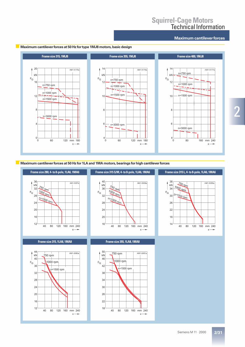
Maximum cantilever forces
2/31Siemens M 11 · 2000
2
Squirrel-Cage MotorsTechnical Information
Frame size 315, 1MJ8 Frame size 400, 1MJ8Frame size 355, 1MJ8
14
10
8
6
80 160 240mm
kN
FQ
x
M1-5177a
4
12
0
n=1500 rpm
n=1000 rpm
n=750 rpm
n=3000 rpm
A14
10
8
6
60 120 180mm
kN
FQ
x
M1-5176a
4
12
0
A
n=1500 rpm
n=1000 rpm
n=750 rpm
n=3000 rpm
20
12
8
4
60 120 180mm
kN
FQ
x
M1-5175a
0
16
0
n=750 rpm
n=1000 rpm
n=1500 rpm
n=3000 rpm
A
Frame size 280, 4- to 8-pole, 1LA6, 1MA6 Frame size 315 L, 4- to 8-pole, 1LA6, 1MA6Frame size 315 S/M, 4- to 8-pole, 1LA6, 1MA6
36
32
28
24
20
16
1240 80 120 160 240mm
kN
FQ
x
M1-5057a
n=1500 rpm
750 rpm1000 rpm
A
Frame size 355, 1LA8, 1MA8
50
46
42
38
34
30
26
40 80 120 160 240mm
kN
FQ
x
M1-5081a
18
22
n=1500 rpm
750 rpm
1000 rpm
A
Frame size 315, 1LA8, 1MA8
44
40
36
32
28
24
20
40 80 120 160 240mm
kN
FQ
x
M1-5080a
12
16
n=1500 rpm
750 rpm
1000 rpm
A
38
34
30
26
22
18
1440 80 120 160 240mm
kN
FQ
x
M1-5059a
n=1500 rpm
750 rpm1000 rpm
A40
36
32
28
24
20
1640 80 120 160 240mm
kN
FQ
x
M1-5058a
n=1500 rpm
750 rpm1000 rpm
A
Maximum cantilever forces at 50 Hz for type 1MJ8 motors,basic design
Maximum cantilever forces at 50 Hz for 1LA and 1MA motors,bearings for high cantilever forces
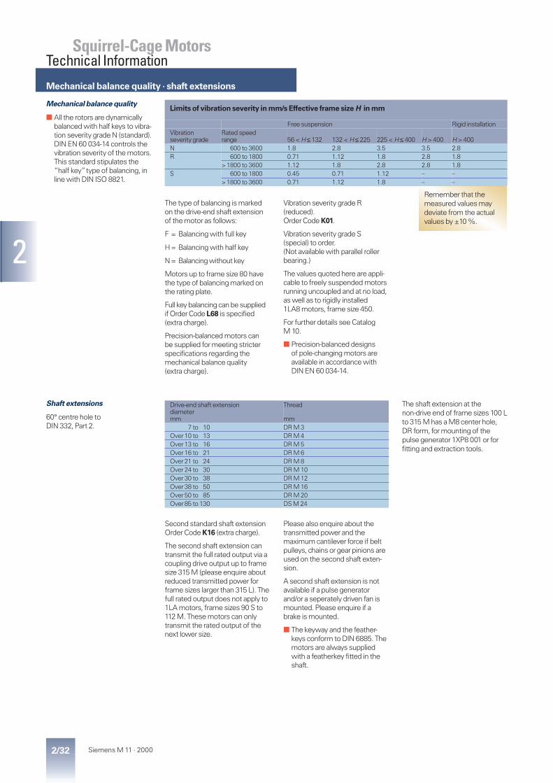
2/32 Siemens M 11 · 2000
2
Squirrel-Cage MotorsTechnical Information
Mechanical balance quality
■ All the rotors are dynamicallybalanced with half keys to vibra-tion severity grade N (standard).DIN EN 60 034-14 controls thevibration severity of the motors.This standard stipulates the“half key”type of balancing, inline with DIN ISO 8821.
The type of balancing is markedon the drive-end shaft extensionof the motor as follows:
F = Balancing with full key
H= Balancing with half key
N= Balancing without key
Motors up to frame size 80 havethe type of balancing marked onthe rating plate.
Full key balancing can be suppliedif OrderCode L68 is specified(extra charge).
Precision-balanced motors canbe supplied for meeting stricterspecifications regarding themechanical balance quality(extra charge).
Vibration severity grade R(reduced).Order Code K01.
Vibration severity grade S(special) to order.(Not available with parallel rollerbearing.)
The values quoted here are appli-cable to freely suspended motorsrunning uncoupled and at no load,as well as to rigidly installed1LA8 motors, frame size 450.
For further details see CatalogM 10.
■ Precision-balanced designsof pole-changing motors areavailable in accordance withDIN EN 60 034-14.
Limits of vibration severity in mm/s Effective frame size H in mm
Free suspension Rigid installationVibrationseverity grade
Rated speedrange 56 < H ≤ 132 132 < H ≤ 225 225 < H ≤ 400 H > 400 H > 400
N 600 to 3600 1.8 2.8 3.5 3.5 2.8R 600 to 1800 0.71 1.12 1.8 2.8 1.8
>1800 to 3600 1.12 1.8 2.8 2.8 1.8S 600 to 1800 0.45 0.71 1.12 – –
>1800 to 3600 0.71 1.12 1.8 – –
Shaft extensions
60° centre hole toDIN 332, Part 2.
Second standard shaft extensionOrder Code K16 (extra charge).
The second shaft extension cantransmit the full rated output via acoupling drive output up to framesize 315 M (please enquire aboutreduced transmitted power forframe sizes larger than 315 L). Thefull rated output does not apply to1LA motors, frame sizes 90 S to112 M. These motors can onlytransmit the rated output of thenext lower size.
Please also enquire about thetransmitted power and themaximum cantilever force if beltpulleys, chains or gear pinions areused on the second shaft exten-sion.
A second shaft extension is notavailable if a pulse generatorand/or a seperately driven fan ismounted. Please enquire if abrake is mounted.
■ The keyway and the feather-keys conform to DIN 6885. Themotors are always suppliedwith a featherkey fitted in theshaft.
The shaft extension at thenon-drive end of frame sizes 100 Lto 315 M has a M8 center hole,DR form, for mounting of thepulse generator 1XP8 001 or forfitting and extraction tools.
Drive-end shaft extensiondiametermm
Thread
mm7 to 10 DR M 3
Over10 to 13 DR M 4Over13 to 16 DR M 5Over16 to 21 DR M 6Over21 to 24 DR M 8Over24 to 30 DR M 10Over30 to 38 DR M 12Over38 to 50 DR M 16Over50 to 85 DR M 20Over85 to 130 DS M 24
Remember that themeasured values maydeviate from the actualvalues by ±10 %.
Mechanical balance quality · shaft extensions

2/33Siemens M 11 · 2000
2
Squirrel-Cage MotorsTechnical Information
Maximum axial load
Maximum axial load on vertical type 1LA, 1MA and 1MJ motors
Frame size With shaft extension3000 rpm 1500 rpm 1000 rpm 750 rpmdownwards upwards downwards upwards downwards upwards downwards upwardsLoaddown
Loadup
Loaddown
Loadup
Loaddown
Loadup
Loaddown
Loadup
Loaddown
Loadup
Loaddown
Loadup
Loaddown
Loadup
Loaddown
Loadup
N N N N N N N N N N N N N N N N56 80 245 230 95 80 330 310 95 80 410 390 95 – – – –63 80 245 230 95 80 330 310 95 80 410 390 95 – – – –71 105 365 335 130 90 380 440 130 90 590 550 130 90 700 660 13080 110 425 360 160 100 540 480 165 100 650 590 165 100 760 700 16590 110 440 360 180 100 680 580 190 100 920 820 190 100 1150 1050 190
100 140 700 550 280 130 990 820 285 130 1280 1110 285 130 1560 1390 285112 140
(140)*710(1050)*
550(800)*
300(300)*
130(130)*
1000(1350)*
820(1100)*
310(300)*
130(130)*
1290(1720)*
1110(1500)*
310(310)*
130(130)*
1570(2000)*
1390(1850)*
310(310)*
132 200(1500)*
1200(1550)*
950(1300)*
470(470)*
180(1500)*
1680(2100)*
1200(1600)*
470(470)*
180(280)*
1900(2400)*
1600(2100)*
470(470)*
190(290)*
2200(2800)*
1900(2400)*
440(440)*
160 1500(2000)*
1400(1720)*
950(1300)*
1900(2500)*
1900(2500)*
1800(2400)*
1300(1720)*
2200(2800)*
2200(2800)*
2200(2800)*
1600(2130)*
2700(3600)*
2700(3600)*
2700(3600)*
1950(2600)*
2900(3700)*
For 1LG8 motors
90 650 720 650 720 880 960 880 960 1100 1150 1100 1150 1200 1300 1200 1300100 620 750 620 750 840 1000 840 1000 1100 1150 1100 1150 1150 1300 1150 1300112 850 990 850 990 1100 1350 1100 1350 1350 1550 1350 1550 1550 1750 1550 1750132 1200 1450 1200 1450 1650 1900 1650 1900 1900 2300 1900 2300 2200 2600 2200 2600160 1400 1900 1400 1900 1900 2500 1900 2500 2200 3000 2200 3000 2600 3300 2600 3300
Maximum axial load on horizontal type 1LA, 1MA and 1MJ motors
Frame size 3000 rpm 1500 rpm 1000 rpm 750 rpmTensileload
Thrust load (N) Tensileload
Thrust load (N) Tensileload
Thrust load (N) Tensileload
Thrust load (N)with radialload at
withoutradialload
with radialload at
withoutradialload
with radialload at
withoutradialload
with radialload at
withoutradialload
N x0 xmax. N x0 xmax. N x0 xmax. N x0 xmax.
56 90 120 90 240 90 140 110 320 90 170 120 400 – – – –63 90 120 90 240 90 140 110 320 90 170 120 400 – – – –71 120 150 120 350 120 210 150 460 120 260 180 570 120 300 210 68080 140 190 150 400 140 300 260 510 140 330 280 620 140 340 290 73090 150 300 280 400 150 400 360 630 150 480 430 870 150 550 500 1100
100 220 450 350 630 220 600 500 910 220 650 550 1200 220 750 650 1480112 220
(220)*450(850)*
350(700)*
630(1050)*
220(220)*
600(1150)*
500(1000)*
910(1350)*
220(220)*
650(1300)*
550(1150)*
1200(1720)*
220(220)*
750(1450)*
650(1300)*
1480(2000)*
132 350(350)*
650(1000)*
520(900)*
1200(1550)*
350(350)*
850(1250)*
700(1150)*
1600(2100)*
350(350)*
1020(1500)*
890(1400)*
1900(2400)*
350(350)*
1150(1750)*
1020(1650)*
2200(2800)*
160 1500(2100)*
850(1280)*
720(1100)*
1500(2100)*
1500(2100)*
1050(1680)*
920(1700)*
1800(2350)*
1500(2100)*
1250(2050)*
1120(1920)*
2200(2900)*
1500(2100)*
1350(2400)*
1220(2200)*
2600(3300)*
For 1LG8 motors
90 330 560 680 910 750 910 1100 900 1100 1250 1000 1250100 300 500 670 910 700 910 1100 850 1100 1200 1000 1200112 670 670 900 1200 900 1200 1400 1100 1400 1600 1300 1600132 970 970 1300 1750 1200 1750 2100 1500 2100 2400 1700 2400160 1200 1200 1600 2100 1500 2100 2500 1800 2500 2900 2200 2900
Values shown without as-suming a cantilever forceon the shaft end.
■ The maximum loads referto 50 Hz operation; Pleaseinquire about 60 Hz operation.
The figures for the maximumaxial loads have been calculatedassuming the maximum permit-ted cantilever force.
Please ask for advice if the loadingdirection alternates (i.e. if the sidefrom which the load is appliedchanges).
* Bracketed values with framesizes 112 to 160 apply to1MJ6 motors

Maximum axial load
2/34 Siemens M 11 · 2000
2
Squirrel-Cage MotorsTechnical Information
Maximum axial load on vertical type 1LA, 1MA and 1MJ motors(without assuming a cantilever force on the shaft end)
For motors With shaft extension downwards3000 rpm 1500 rpm 1000 rpm 750 rpmLoaddown
Loadup
Loaddown
Loadup
Loaddown
Loadup
Loaddown
Loadup
Framesize
Type1LA5 . . .1LA6 . . .1MA6 . . .1MJ6 . . .
1LA5...1LA6...1MA6...
1MJ6... 1LA5...1LA6...1MA6...
1MJ6... 1LA5...1LA6...1MA6...
1MJ6... 1LA5...1LA6...1MA6...
1MJ6... 1LA5...1LA6...1MA6...
1MJ6... 1LA5...1LA6...1MA6...
1MJ6... 1LA5...1LA6...1MA6...
1MJ6... 1LA5...1LA6...1MA6...
1MJ6...
N N N N N N N N N N N N N N N N180 M180 L
. . . . 183
. . . . 1861150
–1150
–1900
–1900
–14001400
14001400
23502400
23502400
–1700
–1700
–2850
–2850
–2000
–2000
–3150
–3150
200 L . . . . 206. . . . 207
16501550
16501550
27502800
27502800
–2000
–2000
–3350
–3350
25502400
25502400
39503950
39503950
–2800
–2800
–4500
–4500
225 S225 M
. . . . 220
. . . . 223–
1890–
1890–
2190–
219023002180
23002180
30203060
30203060
–2700
–2700
–3500
–3500
32003040
32003040
40804120
40804120
250 M . . . . 253 1750 1750 2790 2790 2160 2160 3760 3760 2740 2740 4340 4340 2990 2990 4890 4890280 S280 M
. . . . 280
. . . . 283380180
1150900
44804580
38503900
38303550
13501000
87908910
49505000
53405000
23502000
1000010100
56505700
62805930
28502450
1100011100
62506300
315 S315 M
. . . . 310
. . . . 313210100
900650
52705350
45004550
37003330
17001600
1020010400
64006900
51504740
23002050
1170011700
70507500
65205801
34002800
1300013000
79508400
315 L . . . . 316. . . . 317. . . . 318
927092709270
–––
770840840
–––
233013701370
–––
104001080010800
–––
365029902990
–––
117001160011600
–––
463037603760
–––
130001300013000
–––
1LA8 . . .1MA8 . . . N N N N N N N N
315 . . . . 315. . . . 317
43003790
15501830
1110010600
22102550
1250011800
28803360
1430013600
30003440
355 . . . . 353 5320 1850 13100 3050 – – – –. . . . 355. . . . 357
50004240
20302480
1270011800
32603760
1410012900
45305410
1630015100
46605530
400 . . . . 403. . . . 405. . . . 407
346029502500
313034303710
157001500014300
414045805070
175001660015700
614067207320
202001660018500
638069607570
450 . . . . 453. . . . 455. . . . 457
356029002240
356039804440
144001360012800
601065207110
163001540014200
823089209790
193001830017200
85309230
10100
■ The maximum loads referto 50 Hz operation; Pleaseinquire about 60 Hz operation.
The figures for the maximumaxial loads have been calculatedassuming that standard couplingtypes are used for the drive.See Part 8 for sources.
Please inquire about1MJ8 motors.
Please ask for advice if theloading direction alternates.

2/35Siemens M 11 · 2000
2
Squirrel-Cage MotorsTechnical Information
Maximum axial load on horizontal type 1LA, 1MA and 1MJ motors
For motors 3000 rpm 1500 rpm 1000 rpm 750 rpmFramesize
Type1LA5 . . .1LA6 . . .1MA6 . . .1MJ6 . . .
Loading direction Loading direction Loading direction Loading directionTension Thrust Tension Thrust Tension Thrust Tension Thrust
N N N N N N N N180 M180 L
. . . . 183
. . . . 1861400
–1400
–17001700
17001700
–2050
–2050
–2400
–2400
200 L . . . . 206. . . . 207
20001950
20001950
–2450
–2450
30002900
30002900
–3400
–3400
225 S225 M
. . . . 220
. . . . 223–
2390–
137029802900
19601880
–3380
–2360
38803810
28602790
250 M . . . . 253 2450 1655 3070 2270 3620 2820 4000 3200280 S280 M
. . . . 280
. . . . 2831330 (3700)*1200 (3600)*
2900 (2100)*2800 (2000)*
5080 (4200)*4990 (4000)*
6740 (2600)*6650 (2400)*
6410 (5000)*6260 (4800)*
8070 (3400)*7920 (3200)*
7390 (5550)*7220 (5350)*
9050 (3950)*8880 (3750)*
315 S315 M
. . . . 310
. . . . 3131500 (3800)*1400 (3650)*
3160 (2200)*3180 (2050)*
5350 (4900)*5260 (4900)*
7450 (3300)*7360 (3300)*
6740 (5500)*6560 (5450)*
8810 (3900)*8660 (3850)*
8010 (6500)*7690 (6250)*
10110 (4900)*9790 (4650)*
315 L . . . . 316. . . . 317. . . . 318
1080940940
274026002600
458041704170
668062706270
577054105410
787075107510
682064106410
892085108510
1LA8 . . .1MA8 . . . N N N N N N N N
315 . . . . 315. . . . 317
26402640
26402640
51905190
51905190
61906190
61906190
70307030
70307030
355 . . . . 353. . . . 355. . . . 357
332033203320
332033203320
659065906590
659065906590
–78707870
–78707870
–89308930
–89308930
400 . . . . 403. . . . 405. . . . 407
332033203320
332033203320
781078107810
781078107810
934093409340
934093409340
106001060010600
106001060010600
450 . . . . 453. . . . 455. . . . 457
431043104310
431043104310
846084608460
846084608460
101001010010100
101001010010100
115001150011500
115001150011500
Paint finish
■ The 1LA7, 1MA7, 1LA5 and1MA6/1MJ6 motors up toframe size 200 L are suppliedwith the special paint finish asstandard.
They can be painted over withany normal type of paint.
When no color is specified themotor is painted in the colorRAL 7030.
Paintwork Suitability for climate groupsto DIN IEC 60 721, Part 2 – 1
Standard finish Moderate (extended)for indoors and outdoors
Short per.:Contin.:
up to 120 °Cup to 100 °C
Special finish Worldwide (global)for outdoors
Short per.:Contin.:
up to 140 °Cup to 120 °C
Also: For aggressive atmospheresup to 1 % acid and alkaliconcentration or permanentdampness in sheltered rooms
■ The maximum loads referto 50 Hz operation; Pleaseinquire about 60 Hz operation.
The figures for the maximumaxial loads have been calculatedassuming that standard couplingtypes are used for the drive.See Part 9 for sources.
Please inquire about1MJ8 motors.
Please ask for advice if theloading direction alternates.
* The values in brackets referto 1MJ6 motors with frame sizes280 S to 315 M for 1MJ6 motors.
Maximum axial load · paint finish

Modular technology
2/36 Siemens M 11 · 2000
2
Squirrel-Cage MotorsTechnical Information
Description
The range of potential applica-tions can be broadened consider-ably in combination with thefollowing built-on accessories(e.g. the motors can be used asbrake motors).
■ with pulse generator 1XP8 001,frame sizes 100 L to 315 L
■ with separately driven fan2CW2, frame sizes 100 L to225 M
■ with brake 2LM8, frame sizes63 to 225 M
The brake must always bemounted in the factory for safetyreasons.
The pulse generator and/or theseparately driven fan can also beretrofitted.
The degree of protection for mo-tors with built-on accessories isIP 55.
Technical data of the separately driven fan
Frame size Rated voltagerange
Frequency Rated speed Rated output Rated current
V Hz rpm kW A100 L 200 to 290 B
346 to 500 *200 to 290 B346 to 500 *
50506060
2680268030003000
0.0620.0620.0520.052
0.240.140.160.09
112 M 200 to 290 B346 to 500 *200 to 290 B346 to 500 *
50506060
2760276031203120
0.0970.0970.0980.098
0.430.250.290.17
132 S/M 200 to 290 B346 to 500 *200 to 290 B346 to 500 *
50506060
2690269029602960
0.1640.1640.2120.212
0.590.340.520.30
160 M to 225 M 200 to 290 B346 to 500 *200 to 290 B346 to 500 *
50506060
2690269029802980
0.2690.2690.3540.354
0.950.550.840.48
Technical data of pulse generators
Supply voltage UB 1XP8 001-1 (HTL version)+10 V to +30 V
1XP8 001-2 (TTL version)5 V ±10 %
Current input without load 200 mA 150 mAMaximum load current per output max. 100 mAPulses per revolution 1024Outputs 2 square-wave pulses A, B - 2 inverted square-wave pulses A, B
Zero pulse and inverted zero pulsePulse offset between the two outputs 90° ± 20 %Output amplitude UHigh > UB – 3.5 V
ULow < 3 VUHigh ≥ 2.5 VULow ≤ 0.5 V
Minimum edge interval 0.8 µs at 160 kHz 0.45 µs at 300 kHzEdge steepness (without load or cable) t+, t– ≤ 200 ns t+, t– ≤ 100 nsMaximum frequency 160 kHz 300 kHzMaximum speed 9000 rpm 12000 rpmTemperature range –20 °C to +100 °CDegree of protection IP 66Maximum radial cantilever force 60 NMaximum axial force 40 NTermination system 12-way plug (socket supplied)
Modular Technology for 1LA motors
Pulse generator 1XP8 001
The pulse generator can be sup-plied already mounted in an HTLversion as 1XP8 001-1 (OrderCode H57) or in a TTL version as1XP8 001-2 (Order Code H58).
It can also be ordered and fittedseparately (Order No. 1XP8 001-1or 1XP8 001-2, part 8). All 1LA5and 1LA7 motors with frame sizesfrom 100 L to 315 L that are listedin this catalog are prepared for fit-ting a pulse generator on thenon-drive end.
The pulse generator can only befitted on a standard non-drive end,i.e. a second shaft extension or acanopy can no longer be supplied.
Separately driven fan 2CW2
The use of a separately drivenfan is recommended to increasemotor utilization at low speedsand to limit noise generation atspeeds significantly higher thanthe synchronous speed. In bothcases, this refers to converter-fedoperation only. Please enquireabout traction and vibratory opera-tion.
The separately driven fan canbe supplied already fitted.Order Code G17.
It can also be ordered and fittedseparately (see Accessories, part8, for selection information andorder numbers).
The seperately drive fan has a rat-ing plate with all important data.Please note the fan's direction ofrotating when connecting up.

Modular technology
2/37Siemens M 11 · 2000
2
Squirrel-Cage MotorsTechnical Information
Technical data
Supply voltage UB +9 V to +30 VCurrent input without load 50 to 100 mAMaximum load current per output 60 mAPulses per revolution 1024Outputs 4 short-circuit-proof squ.-wave
pulses A, B and A, BPulse offset between thetwo outputs
90° ± 20 %
Output amplitude UHigh ≥ UB – 3.5 VULow ≤ 1.5 V
Pulse duty factor 1 : 1 ± 20 %Edge steepness 10 V/µsMaximum frequency 120 kHzMaximum speed 7000 rpmTemperature range –20 °C to +100 °CDegree of protection IP 55Maximum radial cantilever force 150 NMaximum axial force 100 NTermination system Radial right-angle connectorMech. design acc. to Ident. No. 73 522 B
Supply voltage UB +9 V to +26 VCurrent input without load Approx. 90 mAMaximum load current per output 60 mAPulses per revolution 1024Outputs 4 short-circuit-proof squ.-wave
pulses A, B and A, BPulse offset between thetwo outputs
90° ± 20 %
Output amplitude UHigh ≥ UB – 3.5 VULow ≤ 1.5 V
Pulse duty factor 1 : 1 ± 20 %Edge steepness 10 V/µsMaximum frequency 120 kHzMaximum speed 4000 rpmTemperature range –20 °C to +85 °CDegree of protection IP 66Maximum radial cantilever force 50 NMaximum axial force 80 NTermination system Terminals,
Pg 9 cable connectionMech. design acc. to Ident. No. 74 055 B
Supply voltage UB +9 V to +30VCurrent input without load 90 mAMaximum load current per output 40 mAPulses per revolution 1024Outputs 6 short-circuit-proof squ.-wave
pulses A, A’, B, B’, 0, 0’Pulse offset between thetwo outputs
90° ± 25o el.
Output amplitude UHigh>20 VULow < 2.5 V
Pulse duty factor 1 : 1 ± 10 %Edge steepness 50 V/µs (without load)Maximum frequency 100 kHz with 350 m cableMaximum speed 3500 rpmTemperature range –20 °C to +80 °CDegree of protection IP 65Maximum permissible radialcantilever force
300 N
Maximum permissible axial force 100 NTermination system Terminals in generator Pg 9
radial cable connection
Other pulse generators
for frame sizes 100 to 450 1)
HOG9 D 1024 I pulse generator
■ The HOG9 D 1024 I pulse generator can besupplied already fitted. Order Code H72.
■ The HOG9 pulse generator can be providedby the customer and fitted by Siemens.Order Code H74.
■ The HOG9 pulse generator can also be fittedseparately. The motor must be prepared forthis purpose. Order Code H79 must bespecified in the order. The pulse generatoris not part of the scope of supply.
HOG10 D 1024 I pulse generator
This generator is very robust and thereforesuitable for service in harsh environments.
■ The HOG10 D 1024 pulse generator canbe supplied already fitted. Order Code H73.
■ The HOG10 pulse generator can be suppliedby the customer and fitted by Siemens.Order Code H75.
■ The HOG10 pulse generator can also befitted separately. The motor must beprepared for this purpose. Order Code H80must be specified in the order. The pulsegenerator is not part of the scope of supply.
112
Æ1
05
M1-5
201
Æ16
G7
104,5
M1
-52
00 ~67
Æ 88
Æ16
G7
XH 860 900 220 rotary pulse generator
This generator is very robust and thereforesuitable for service in harsh environments.It is shock-free and vibration-proof.
■ The XH 860 900 220 rotary pulse generatorcan be supplied already fitted.Order code H70.
■ The XH 860 900 220 pulse generator can beprovided by the customer and installed bySiemens. Order code H71.
■ The XH 860 900 220 pulse generator canalso be fitted separately. The motor must beprepared for this purpose. Order Code H78must be specified. The pulse generator isnot part of the scope of supply.
79
Æ16
G7
~ Æ1
00
M1-5
202
Further mounting parts for 1LA motors (not in combination with modular technology)
1) Please inquire for 1LA9 motors.
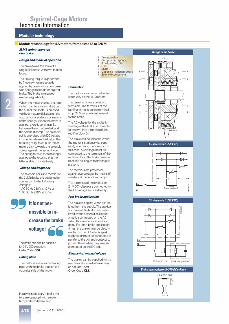
Modular technology
2/38 Siemens M 11 · 2000
2
Squirrel-Cage MotorsTechnical Information
2LM8 spring-operated
disk brake
Design and mode of operation
The brake takes the form of asingle-disk brake with two frictionfaces.
The braking torque is generatedby friction when pressure isapplied by one or more compres-sion springs to the de-energizedbrake. The brake is releasedelectromagnetically.
When the motor brakes, the rotor- which can be axially shifted onthe hub or the shaft - is pressedvia the armature disk against theopp. frictional surfaces by meansof the springs. When the brake isapplied, there is an air gap SLü
between the armature disk andthe solenoid comp. The solenoidcoil is energized with DC voltagein order to release the brake. Theresulting mag. force pulls the ar-mature disk towards the solenoidcomp. against the spring force.The spring force is then no longerapplied to the rotor, so that thelatter is able to rotate freely.
Voltage and frequency
The solenoid coils and rectifier ofthe 2LM8 brake are designed forconnection to the followingvoltages:1 AC 50 Hz 230 V ± 10 % or1 AC 60 Hz 230 V ± 10 %.
Thebrakecanalsobesuppliedfor24VDCexcitation.OrderCode C00.
Rating plate
The motors have a second ratingplate with the brake data on theopposite side of the motor.
Inquiry is necessary if brake mo-tors are operated with ambienttemperatures below zero.
Connection
The motors are connected in thesame way as the 1LA motors.
The terminal boxes contain sixterminals. The terminals of therectifier or those on the terminalstrip (24 V version) can be usedfor the brake.
The AC voltage for the excitationwinding of the brake is connectedto the two free terminals of therectifier block (~).
The brake can be released whenthe motor is stationary by sepa-rately energizing the solenoid. Inthis case, AC voltage must beconnected to the terminals of therectifier block. The brake remainsreleased as long as this voltage ispresent.
The rectifiers are protectedagainst overvoltages by means ofvaristors at the input and output.
The terminals of the brakes for24 V DC voltage are connected tothe DC voltage source directly.
Fast brake application
The brake is applied when it is iso-lated from the supply. The applica-tion time of the brake disk is de-layed by the solenoid coil induct-ance (disconnected on the ACside). This involves a significantdelay. For short brake applicationtimes, the brake must be discon-nected on the DC side. A sparksuppressor must be connected inparallel to the coil and contacts toprotect them when they are dis-connected on the DC side.
Mechanical manual release
The brakes can be supplied with amechanical manual release usingan actuator lever.Order Code K82.
Modular technology for 1LA motors, frame sizes 63 to 225 M
1 Armature disk2 Compression springs3 Axially sliding rotor4 Hub5 Shaft6 Opposing frictional surface7 Solenoid component
Design of the brake
AC side switch (230 V AC)
DC side switch (230 V DC)
Brake connection with 24 V DC voltage
LÜ
SA1-5018
2
S
6
1
4
3 2
5
7
SA
1-50
19b
+
L1
N
L+ L-
M1-
5179
+
SA
1-50
20b
L1
N
Solenoid coil
Solenoid coil
Solenoid coil
Spark suppressor
|| It is not per-
missible to in-
crease the brake
voltage!{{

Modular technology
2/39Siemens M 11 · 2000
2
Squirrel-Cage MotorsTechnical Information
Explanations
Performance of spring-operated brakes with standard excitation Brake ratingFor motorsFrame size
Brake type Rated braketorque at100 rpm
Power input Brakeapplicationtime1)
Brakereleasetime
Brakemomentof inertia
Noise levelLp with ratedair gap
Lifetime ofbrakelining L
Air gapadjustmentrequired afterbraking energy LN
Nm A W ms ms kg m2 dB (Al) Nm x 106 Nm x 106
63 2LM8 005–1NA10 5 0.1 20 17 35 0.000013 77 105 1671 2LM8 005–2NA10 5 0.1 20 17 35 0.000013 77 105 1680 2LM8 010–3NA10 10 0.12 25 20 50 0.000045 74 270 2990 2LM8 020–4NA10 20 0.15 30 30 90 0.00016 75 740 79
100 2LM8 040–5NA10 40 0.2 40 40 120 0.00036 80 1350 115112 2LM8 060–6NA10 60 0.25 50 65 150 0.00063 77 1600 215132 2LM8 100–7NA10 100 0.27 55 90 180 0.0015 75 2450 325160 2LM8 240–8NA10 240 0.5 100 200 400 0.0073 79 7300 935180 2LM8 300–0NA10 300 0.5 100 200 400 0.0073 79 5500 470200,225
2LM8 400–0NA10 400 0.55 110 270 500 0.0200 93 9450 1260
Permissible switching energy as a function of operating frequency
M1-5147
104
103
102
101
102
10
103
104
105
h-1
J
2LM8 400
2LM8 300
2LM8 240
2LM8 100
2LM8 060
2LM8 040
2LM8 020
2LM8 010
2LM8 005
Operating frequency Sn
Perm
issi
ble
sw
itchin
g e
nerg
y Q
ma
x.
A
1) The specified switching times are valid forswitching on the DC side with a nom. releasetravel and with the coil already warm. They areaverage values which may vary among otherthings according to the rectifier type and therelease travel. The brake application time forswitching on the AC side, for example, is approx.6 times longer than for switching on the DC side.
Lifetime of the brake lining
The braking energy LN until the brake needs tobe adjusted depends on various factors, andparticularly on the masses that are braked, theoperating speed, the operating frequency andthus the temperature on the friction faces. It istherefore not possible to specify a value for thefriction energy until readjustment that is validfor all operating conditions.
The specific wear on the friction faces (volumeof wear per unit of friction energy) is approxi-mately 0.05 to 2 cm³/kWh when the brake isused as a service brake.
Maximum speeds
Please refer to the table on page 2/40 for themaximum speeds at which an emergencystop is permissible. These speeds should beconsidered as recommended values andconfirmed by testing under actual operatingconditions.
The maximum permitted braking energydepends on the operating frequency and isshown for the various brakes on the graphopposite (“Permissible switching energy as afunction of operating frequency”). Greaterwear occurs during emergency braking.
Modular technology for 1LA motors, frame sizes 63 to 225 M (continued)

Modular technology
2/40 Siemens M 11 · 2000
2
Squirrel-Cage MotorsTechnical Information
Readjusting the air gapChanging the braking torque
The brake is supplied with a preset torque.It is possible to reduce this torque to thedimension o1 by unscrewing the adjusting ringwith a hook spanner.
The braking torque changes by the valuesshown in the above table for each notch of theadjusting ring.
Readjusting the air gap
Under normal operating conditions, the brakeis practically maintenance-free.
The air gap sLü must be checked at regularintervals if the application requires a very largeamount of friction energy, and readjusted tothe rated gap sLüNenn at the latest when themaximum air gap sLümax. is reached.
Explanations
Max. rpm Change in braking torque Readjustment of air gapFor motorsFrame size
Brake type Max. operatingrpm if max.switching energyutilized
Max. no-load rpm withemergency stop function
Reductionper notch
Dim.“o1“
Min.brakingtorque
Ratedair gapsLüNenn
Max.air gapsLümax.
Min. rotorthicknesshmin.
Horizontalmounting
Verticalmounting
rpm rpm rpm Nm mm Nm mm mm mm63 2LM8 005–1NA10 3000 6000 6000 0.19 4.5 4.4 0.2 0.4 4.371 2LM8 005–2NA10 3000 6000 6000 0.19 4.5 4.4 0.2 0.4 4.380 2LM8 010–3NA10 3000 6000 6000 0.36 4.5 8.5 0.2 0.4 5.390 2LM8 020–4NA10 3000 6000 6000 0.6 7.5 19 0.2 0.5 7.3
100 2LM8 040–5NA10 3000 6000 6000 1.2 9.5 22 0.3 0.5 6.0112 2LM8 060–6NA10 3000 6000 6000 1.5 11.0 40 0.3 0.8 6.0132 2LM8 100–7NA10 3000 5300 5000 2.1 10.0 40 0.3 0.8 7.0160 2LM8 240–8NA10 1500 4400 3200 3.0 15.0 150 0.4 1.2 9.6180 2LM8 300–0NA10 1500 4400 3200 3.0 17.0 184 0.4 0.8 9.6200,225
2LM8 400–0NA10 1500 3000 3000 4.7 19.5 290 0.5 1.4 12.5
SA1-5022
hmin. SLü O1O(S )Lü Nenn
(S )Lü max.
Modular technology for 1LA motors, frame sizes 63 to 225 M (continued)

3
3/1Siemens M 11 · 2000
Squirrel-Cage MotorsBasic
DesignAluminum enclosure
3/23/4
Energy-saving motor to CEMEP“Improved Efficiency”eff2“High Efficiency”eff1
3/6 Energy-saving motor to EPACT3/8 With increased output3/9 Pole-changing
Cast-iron enclosure
3/123/16
Energy-saving motor to CEMEP“Improved Efficiency”eff2“High Efficiency”eff1
3/17 Energy-saving motor to EPACT3/18 Pole-changing
3/21 Motors for converter-fed operation
Motors for duty atSIMOVERTâMASTERDRIVES
3/22 with standard insulation for£ 500 V3/23 with special insulation for 690 V
3/25 Special designs
1LA5 to 1LA8 motors
Frame sizes 56 to 450Output range 0.06 to 1000 kWClass F Utilization acc. to BSuitable for con- Voltage front timesverter-fed operation ts > 0.1 ms at U£ 500 V
Ex-stock designs permanently available.See M 11 Price List for selection information.
Energy saving motors to CEMEP
Number of poles: 2 and 4Output range 1.1 to 90 kWEff1 High EfficiencyEff2 Improved EfficiencyEfficiency acc. to IEC 60 034-2
The motors are stamped on the rating plate and onthe packing. Efficiency at 3/4 and 4/4 loads is recorded.Only licensed manufacturers are allowed to stamp.Considerable savings in energy have become realitywith the optimized motor series.
Energy-saving motors to EPACT
Number of poles 2, 4 and 6Output range 1 to 200 HPMinimum efficiencies laid down by U.S. laws.Efficiency according to IEEE 112b
The nominal efficiency and NEMA MG-1 is stampedon the rating plate.
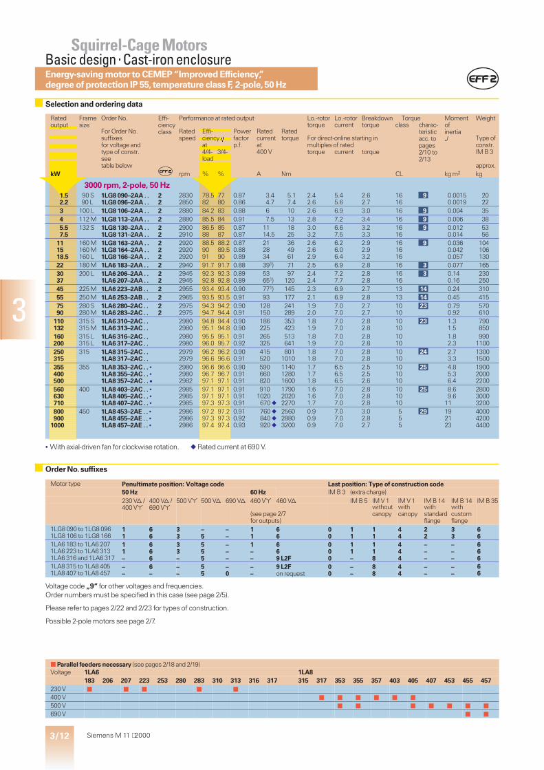
3
3/12 Siemens M 11 ⋅ 2000
Motor type Penultimate position: Voltage code Last position: Type of construction code50 Hz 60 Hz IM B 3 (extra charge)230 Vd/ 400 Vd/ 500 V* 500 Vd 690 Vd 460 V* 460 Vd IM B 5 IM V 1 IM V 1 IM B 14 IM B 14 IM B 35400 V* 690 V*
(see page 2/7for outputs)
withoutcanopy
withcanopy
withstandardflange
withcustomflange
1LG8 090 to 1LG8 0961LG8 106 to 1LG8 166
11
66
33
–5
––
11
66
00
11
11
44
22
33
66
1LA6 183 to 1LA6 2071LA6 223 to 1LA6 3131LA6 316 and 1LA6 317
11–
666
33–
555
–––
1––
669 L2F
000
11–
118
444
–––
–––
666
1LA8 315 to 1LA8 4051LA8 407 to 1LA8 457
––
6–
––
55
–0
––
9 L2Fon request
00
––
88
44
––
––
66
Voltage code „9“ for other voltages and frequencies.Order numbers must be specified in this case (see page 2/5).
Please refer to pages 2/22 and 2/23 for types of construction.
Possible 2-pole motors see page 2/7.
Ratedoutput
Framesize
Order No. Effi-ciencyclass
Performance at rated output Lo.-rotor Lo.-rotor Breakdown Torque MomentofinertiaJ
Weighttorque current torque class charac-
teristicacc. topages2/10 to2/13
For Order No.suffixesfor voltage andtype of constr.seetable below
Ratedspeed
Effi-ciency hat4/4- 3/4-load
Powerfactorp.f.
Ratedcurrentat400 V
Ratedtorque For direct-online starting in
multiples of ratedtorque current torque
Type ofconstr.IM B 3
approx.kW rpm % % A Nm CL kg m2 kg
3000 rpm, 2-pole, 50 Hz1.52.2
90 S90 L
1LG8 090–2AA . .1LG8 096–2AA . .
22
28302850
78.582
7780
0.870.86
3.44.7
5.17.4
2.42.6
5.45.6
2.62.7
1616
9 0.00150.0019
2022
3 100 L 1LG8 106–2AA . . 2 2880 84.2 83 0.88 6 10 2.6 6.9 3.0 16 9 0.004 354 112 M 1LG8 113–2AA . . 2 2880 85.5 84 0.91 7.5 13 2.8 7.2 3.4 16 9 0.006 385.57.5
132 S 1LG8 130–2AA . .1LG8 131–2AA . .
22
29002910
86.588
8587
0.870.87
1114.5
1825
3.03.2
6.67.5
3.23.3
1616
9 0.0120.014
5356
111518.5
160 M160 M160 L
1LG8 163–2AA . .1LG8 164–2AA . .1LG8 166–2AA . .
222
292029202920
88.59091
88.289.590
0.870.880.89
212834
364961
2.62.62.9
6.26.06.4
2.92.93.2
161616
9 0.0360.0420.057
104106130
22 180 M 1LA6 183–2AA . . 2 2940 91.7 91.7 0.88 391) 71 2.5 6.9 2.8 16 3 0.077 1653037
200 L 1LA6 206–2AA . .1LA6 207–2AA . .
22
29452945
92.392.8
92.392.8
0.890.89
53651)
97120
2.42.4
7.27.7
2.82.8
1616
3 0.140.16
230250
45 225 M 1LA6 223–2AB . . 2 2955 93.4 93.4 0.90 771) 145 2.3 6.9 2.7 13 14 0.24 31055 250 M 1LA6 253–2AB . . 2 2965 93.5 93.5 0.91 93 177 2.1 6.9 2.8 13 14 0.45 4157590
280 S280 M
1LA6 280–2AC . .1LA6 283–2AC . .
22
29752975
94.394.7
94.294.4
0.900.91
128150
241289
1.92.0
7.07.0
2.72.7
1010
23 0.790.92
570610
110132
315 S315 M
1LA6 310–2AC . .1LA6 313–2AC . .
29802980
94.895.1
94.494.8
0.900.90
186225
353423
1.81.9
7.07.0
2.82.8
1010
23 1.31.5
790850
160200
315 L315 L
1LA6 316–2AC . .1LA6 317–2AC . .
29802980
95.596.0
95.195.7
0.910.92
265325
513641
1.81.9
7.07.0
2.82.8
1010
1.82.3
9901100
250315
315 1LA8 315–2AC . .1LA8 317–2AC . .
29792979
96.296.6
96.296.6
0.900.91
415520
8011010
1.81.8
7.07.0
2.82.8
1010
24 2.73.3
13001500
355400500
355 1LA8 353–2AC . . •1LA8 355–2AC . . •1LA8 357–2AC . . ·
298029802982
96.696.797.1
96.696.797.1
0.900.910.91
590660820
114012801600
1.71.71.8
6.56.56.5
2.52.52.6
101010
25 4.85.36.4
190020002200
560630710
400 1LA8 403–2AC . . •1LA8 405–2AC . . •1LA8 407–2AC . . •
298529852985
97.197.197.3
97.197.197.3
0.910.910.91
9101020670 f
179020202270
1.61.61.7
7.07.07.0
2.82.82.8
101010
25 8.69.6
11
280030003200
800900
1000
450 1LA8 453–2AE . . •1LA8 455–2AE . . •1LA8 457–2AE . . •
298629862986
97.297.397.4
97.297.397.4
0.910.920.93
760 f840 f920 f
256028803200
0.90.90.9
7.07.07.0
3.02.82.7
555
29 192123
400042004400
• With axial-driven fan for clockwise rotation. f Rated current at 690 V.
■ Parallel feeders necessary (see pages 2/18 and 2/19)Voltage 1LA6 1LA8
183 206 207 223 253 280 283 310 313 316 317 315 317 353 355 357 403 405 407 453 455 457230 V ■ ■ ■ ■ ■
400 V ■ ■ ■ ■ ■ ■
500 V ■ ■ ■ ■ ■ ■ ■
690 V ■ ■
Selection and ordering data
Order No.suffixes
Energy-saving motor to CEMEP “Improved Efficiency”,degree of protection IP 55,temperature class F, 2-pole,50 Hz
Squirrel-Cage MotorsBasic design×Cast-iron enclosure

3
3/13Siemens M 11 ⋅ 2000
Motor type Penultimate position: Voltage code Last position: Type of construction code50 Hz 60 Hz IM B 3 (extra charge)230 Vd/ 400 Vd/ 500 V* 500 Vd 690 Vd 460 V* 460 Vd IM B 5 IM V 1 IM V 1 IM B 14 IM B 14 IM B 35400 V* 690 V*
(see page 2/7for outputs)
withoutcanopy
withcanopy
withstandardflange
withcustomflange
1LG8 090 to 1LG8 0961LG8 106 to 1LG8 166
11
66
33
–5
––
11
66
00
11
11
44
22
33
66
1LA6 183 to 1LA6 2071LA6 220 to 1LA6 3131LA6 316 and 1LA6 317
11–
666
33–
555
–––
1––
669 L2F
000
11–
118
444
–––
–––
666
1LA8 315 to 1LA8 4051LA8 407 to 1LA8 457
––
6–
––
55
–0
––
9 L2Fon request
00
––
88
44
––
––
66
Voltage code „9“ for other voltages and frequencies.Order numbers must be specified in this case (see page 2/5).
Please refer to pages 2/22 and 2/23 for types of construction.
Ratedoutput
Framesize
Order No. Effi-ciencyclass
Performance at rated output Lo.-rotor Lo.-rotor Breakdown Torque MomentofinertiaJ
Weighttorque current torque class charac-
teristicacc. topages2/10 to2/13
For Order No.suffixesfor voltage andtype of constr.seetable below
Ratedspeed
Effi-ciency hat4/4- 3/4-load
Powerfactorp.f.
Ratedcurrentat400 V
Ratedtorque For direct-online starting in
multiples of ratedtorque current torque
Type ofconstr.IM B 3
approx.kW rpm % % A Nm CL kg m2 kg
1500 rpm, 4-pole, 50 Hz1.11.5
90 S90 L
1LG8 090–4AB . .1LG8 096–4AB . .
22
14101415
7779
7780
0.820.82
2.63.5
7.510
2.02.3
5.05.0
2.22.5
1313
12 0.00240.003
2022
2.23
100 L 1LG8 106–4AA . .1LG8 107–4AA . .
22
14001410
8182.5
8182.5
0.830.80
57
1520
2.42.5
5.35.5
2.72.8
1616
9 0.00450.0055
3538
4 112 M 1LG8 113–4AA . . 2 1415 84 84 0.85 8.3 27 2.2 5.9 2.6 16 9 0.012 415.57.5
132 S132 M
1LG8 130–4AA . .1LG8 133–4AA . .
22
14401445
8788
87.588
0.840.84
1115
3750
2.32.6
6.47.0
2.73.1
1616
9 0.0210.028
5969
1115
160 M160 L
1LG8 163–4AA . .1LG8 166–4AB . .
22
14601450
9090.5
9090.8
0.860.83
21.529
7399
2.52.4
6.16.0
2.42.2
1613
912
0.0650.09
108130
18.522
180 M180 L
1LA6 183–4AA . .1LA6 186–4AA . .
22
14601460
90.591.2
90.591.2
0.840.86
3541
121144
2.32.3
7.57.5
3.03.0
1616
3 0.130.15
165180
30 200 L 1LA6 207–4AA . . 2 1465 91.8 91.8 0.86 55 196 2.6 7.0 3.2 16 3 0.24 2403745
225 S225 M
1LA6 220–4AA . .1LA6 223–4AA . .
22
14751475
92.993.4
93.193.6
0.860.87
6780
240292
2.52.6
7.07.0
3.13.2
1616
3 0.440.52
300330
55 250 M 1LA6 253–4AA . . 2 1480 93.8 94.0 0.87 97 355 2.6 6.7 2.5 16 4 0.79 4357590
280 S280 M
1LA6 280–4AA . .1LA6 283–4AA . .
22
14851485
94.394.6
94.394.7
0.860.86
134160
482579
2.52.5
6.76.8
2.72.8
1616
4 1.41.6
610660
110132
315 S315 M
1LA6 310–4AA . .1LA6 313–4AA . .
14861486
94.895.5
94.795.4
0.860.86
194232
707848
2.52.7
6.77.2
2.73.0
1616
4 2.22.7
830910
160200
315 L315 L
1LA6 316–4AA . .1LA6 317–4AA . .
14861488
95.696.2
95.696.1
0.870.87
275345
10301280
2.62.7
7.07.0
2.62.7
1616
3.24.2
10601200
250315
315 1LA8 315–4AB . .1LA8 317–4AB . .
14881488
96.096.3
96.096.3
0.880.88
425540
16002020
1.92.0
6.56.8
2.82.8
1313
18 3.64.4
13001500
355400500
355 1LA8 353–4AB . .1LA8 355–4AB . .1LA8 357–4AB . .
148814881488
96.396.496.8
96.396.496.8
0.870.870.88
610690850
228025703210
2.12.12.1
6.56.56.5
2.62.62.4
131313
18 6.16.88.5
190020002200
560630710
400 1LA8 403–4AB . .1LA8 405–4AB . .1LA8 407–4AB . .
149214921492
96.897.097.0
96.897.097.0
0.880.880.89
9501060690 f
358040304540
1.91.91.9
6.56.86.8
2.72.72.7
131313
26 131416
280030003200
800900
1000
450 1LA8 453–4AC . .1LA8 455–4AC . .1LA8 457–4AC . .
149214921492
97.097.197.1
97.097.197.1
0.880.880.89
780 f880 f970 f
512057606400
1.61.61.7
7.07.07.0
2.62.62.6
101010
26 232628
400042004400
f Rated current at 690 V.
■ Parallel feeders necessary (see pages 2/18 and 2/19)Voltage 1LA6 1LA8
183 186 207 220 223 253 280 283 310 313 316 317 315 317 353 355 357 403 405 407 453 455 457230 V ■ ■ ■ ■ ■ ■
400 V ■ ■ ■ ■ ■ ■
500 V ■ ■ ■ ■ ■ ■ ■
690 V ■ ■
Selection and ordering data
Order No.suffixes
Energy-saving motor to CEMEP “Improved Efficiency”eff2,degree of protection IP 55,temperature class F, 4-pole,50 Hz
Squirrel-Cage MotorsBasic design×Cast-iron enclosure

3/14 Siemens M 11 · 2000
3
Motor type Penultimate position: Voltage code Last position: Type of construction code50 Hz 60 Hz IM B 3 (extra charge)230 Vd/ 400 Vd/ 500 V* 500 Vd 690 Vd 460 V* 460 Vd IM B 5 IM V 1 IM V 1 IM B 14 IM B 14 IM B 35400 V* 690 V*
(see page 2/7for outputs)
withoutcanopy
withcanopy
withstandardflange
withcustomflange
1LG8 090 to 1LG8 0961LG8 106 to 1LG8 166
11
66
33
–5
––
11
66
00
11
11
44
22
33
66
1LA6 186 to 1LA6 2071LA6 223 to 1LA6 3131LA6 316 to 1LA6 318
11–
666
33–
555
–––
1––
669 L2F
000
11–
118
444
–––
–––
666
1LA8 315 to 1LA8 4531LA8 455 and 1LA8 457
––
6–
––
55
–0
––
9 L2Fon request
00
––
88
44
––
––
66
Voltage code “9” for other voltages and/or frequencies.Order numbers must be specified in this case (see page 2/5).
Please refer to pages 2/22 and 2/23 for types of construction.
Ratedoutput
Framesize
Order No. Performance at rated output Lo.-rotor Lo.-rotor Breakdown Torque MomentofinertiaJ
Weighttorque current torque class charac-
teristicacc. topages2/10 to2/13
For Order No.suffixesfor voltage andtype of constr.seetable below
Ratedspeed
Effi-ciencyh
Powerfactorp.f.
Ratedcurrentat400 V
Ratedtorque For direct-online starting in
multiples of ratedType ofconstr.IM B 3
approx.
torque current torque
kW rpm % A Nm CL kg m2 kg
1000 rpm, 6-pole, 50 Hz0.751.1
90 S90 L
1LG8 090–6AD . .1LG8 096–6AB . .
890910
68.369.8
0.750.72
2.23.2
812
1.62.0
3.13.5
1.92.3
713
1512
0.00250.0036
2022
1.5 100 L 1LG8 106–6AB . . 940 76.4 0.70 4.3 15 2.2 4.1 2.5 13 12 0.0086 352.2 112 M 1LG8 113–6AD . . 945 80 0.75 5.5 22 1.8 4.5 2.0 7 15 0.014 38345.5
132 S132 M132 M
1LG8 130–6AA . .1LG8 133–6AB . .1LG8 134–6AA . .
960955955
85.38585
0.800.800.80
6.58.8
11.8
304055
2.62.22.5
5.85.56.0
2.62.62.6
161316
9129
0.030.030.04
596772
7.511
160 M160 L
1LG8 163–6AA . .1LG8 166–6AB . .
965965
87.989
0.820.82
15.322.5
74109
2.52.3
6.56.5
2.82.6
1613
912
0.100.13
108130
15 180 L 1LA6 186–6AA . . 970 89 0.83 29.5 148 2.6 5.7 2.4 16 4 0.2 18018.522
200 L 1LA6 206–6AA . .1LA6 207–6AA . .
975975
90.290.8
0.830.83
35.542.5
181215
2.62.5
5.75.7
2.32.3
1616
4 0.290.33
240255
30 225 M 1LA6 223–6AA . . 978 92.0 0.84 56 293 2.6 5.7 2.2 16 4 0.57 30537 250 M 1LA6 253–6AA . . 980 92.4 0.84 69 361 2.6 6.0 2.1 16 4 0.89 4104555
280 S280 M
1LA6 280–6AA . .1LA6 283–6AA . .
982984
93.093.0
0.860.86
8199
438534
2.42.5
6.06.2
2.32.4
1616
4 1.31.5
540580
7590
315 S315 M
1LA6 310–6AA . .1LA6 313–6AA . .
988988
93.894.2
0.850.85
136162
725870
2.42.4
6.26.2
2.52.5
1616
4 2.42.9
770830
110132160
315 L315 L315 L
1LA6 316–6AA . .1LA6 317–6AA . .1LA6 318–6AA . .
988986988
94.794.795.0
0.850.860.87
198235280
106012801550
2.62.32.4
6.66.66.6
2.52.22.3
161616
3.54.34.9
97010601100
200250
315 1LA8 315–6AB . .1LA8 317–6AB . .
989989
95.795.9
0.870.87
345430
19302410
2.02.0
6.36.3
2.52.5
1313
19 6.07.3
13001500
315400
355 1LA8 355–6AB . .1LA8 357–6AB . .
993993
96.296.5
0.870.87
540690
30303850
2.22.2
6.56.5
2.82.8
1313
19 1316
20002200
450500560
400 1LA8 403–6AB . .1LA8 405–6AB . .1LA8 407–6AB . .
992992992
96.596.596.7
0.860.870.87
780860960
433048105390
2.22.32.3
6.56.56.5
2.82.82.8
131313
19 212427
280030003200
630710800
450 1LA8 453–6AB . .1LA8 455–6AB . .1LA8 457–6AB . .
993993993
96.896.897.0
0.860.870.87
1100710 f790 f
606068307690
2.02.02.0
6.56.56.5
2.62.52.5
131313
20 353944
400042004500
f Rated current at 690 V.
■ Parallel feeders required (see pages 2/18 and 2/19)Spannung 1LA6 1LA8
186 206 207 223 253 280 283 310 313 316 317 318 315 317 355 357 403 405 407 453 455 457230 V ■
400 V ■ ■ ■ ■ ■
500 V ■ ■ ■ ■
Selection and ordering data
Order No.suffixes
Degree of protection IP 55,temperature class F, 6-pole,50 Hz
Squirrel-Cage MotorsBasic design×Cast-iron enclosure

3/15Siemens M 11 · 2000
3
Motor type Penultimate position: Voltage code Last position: Type of construction code50 Hz 60 Hz IM B 3 (extra charge)230 Vd/ 400 Vd/ 500 V* 500 Vd 690 Vd 460 V* 460 Vd IM B 5 IM V 1 IM V 1 IM B 14 IM B 14 IM B 35400 V* 690 V*
(see page 2/7for outputs)
withoutcanopy
withcanopy
withstandardflange
withcustomflange
1LG8 090 to 1LG8 0961LG8 106 to 1LG8 166
11
66
33
–5
––
11
66
00
11
11
44
22
33
66
1LA6 186 to 1LA6 2071LA6 220 to 1LA6 3131LA6 316 to 1LA6 318
11–
666
33–
555
–––
1––
669 L2F
000
11–
118
444
–––
–––
666
1LA8 315 to 1LA8 457 – 6 – 5 – – 9 L2F 0 – 8 4 – – 6
Voltage code “9” for other voltages and/or frequencies.Order numbers must be specified in this case (see page 2/5).
Please refer to pages 2/22 and 2/23 for types of construction.
Ratedoutput
Framesize
Order No. Performance at rated output Lo.-rotor Lo.-rotor Breakdown Torque MomentofinertiaJ
Weighttorque current torque class charac-
teristicacc. topages2/10 to2/13
For Order No.suffixesfor voltage andtype of constr.seetable below
Ratedspeed
Effi-ciencyh
Powerfactorp.f.
Ratedcurrentat400 V
Ratedtorque For direct-online starting in
multiples of ratedType ofconstr.IM B 3
approx.
torque current torque
kW rpm % A Nm CL kg m2 kg
750 rpm, 8-pole, 50 Hz0.370.55
90 S90 L
1LG8 090–8AD . .1LG8 096–8AD . .
690690
6267
0.580.64
1.561.82
5.17.6
1.81.7
2.72.7
1.91.9
77
15 0.00260.0036
2022
0.751.1
100 L 1LG8 106–8AB . .1LG8 107–8AB . .
700700
6969
0.700.70
2.303.28
1015
2.02.0
3.83.7
2.12.1
1313
12 0.00860.01
3538
1.5 112 M 1LG8 113–8AB . . 700 74 0.72 4.20 21 1.9 3.7 2.1 13 12 0.014 402.23
132 S132 M
1LG8 130–8AB . .1LG8 133–8AB . .
715715
81.583
0.700.70
5.607.50
2940
2.02.1
4.44.5
2.32.3
1313
12 0.0320.045
5972
45.57.5
160 M160 M160 L
1LG8 163–8AD . .1LG8 164–8AD . .1LG8 166–8AB . .
715725720
83.58486
0.760.740.74
9.251317.2
5373
100
1.61.82.1
4.34.85.4
2.52.52.6
77
13
151512
0.090.120.16
104108130
11 180 L 1LA6 186–8AB . . 725 87 0.70 24 145 2.0 5.0 2.2 13 14 0.21 17515 200 L 1LA6 207–8AB . . 725 87.5 0.78 32 198 2.1 5.0 2.2 13 14 0.37 24518.522
225 S225 M
1LA6 220–8AB . .1LA6 223–8AB . .
725725
88.690.1
0.800.81
37.543.5
244290
2.12.1
5.05.0
2.22.2
1313
14 0.580.66
300325
30 250 M 1LA6 253–8AB . . 730 91.6 0.81 58 392 2.1 5.0 2.1 13 14 1.1 4353745
280 S280 M
1LA6 280–8AB . .1LA6 283–8AB . .
732734
92.792.8
0.820.83
7084
483585
2.22.2
5.55.5
2.22.2
1313
14 1.41.6
550600
5575
315 S315 M
1LA6 310–8AB . .1LA6 313–8AB . .
738738
93.193.6
0.820.82
104140
712970
2.22.3
6.06.2
2.42.5
1313
14 2.33.0
740850
90110132
315 L315 L315 L
1LA6 316–8AB . .1LA6 317–8AB . .1LA6 318–8AB . .
738738738
93.894.094.0
0.830.830.83
166205245
117014201710
2.32.32.3
6.66.66.6
2.52.52.5
131313
3.64.44.8
99011001200
160200
315 1LA8 315–8AB . .1LA8 317–8AB . .
739739
94.995.2
0.820.82
295370
20702580
2.12.1
6.06.0
2.32.3
1313
21 6.07.3
13001500
250315
355 1LA8 355–8AB . .1LA8 357–8AB . .
741741
95.796.0
0.820.82
460580
32204060
2.12.1
6.16.1
2.42.4
1313
21 1316
20002200
355400450
400 1LA8 403–8AB . .1LA8 405–8AB . .1LA8 407–8AB . .
742742742
96.196.296.3
0.820.820.82
650730820
457051505790
2.02.12.1
6.56.56.5
2.62.62.6
131313
21 212427
280030003200
500560630
450 1LA8 453–8AB . .1LA8 455–8AB . .1LA8 457–8AB . .
744744744
96.496.596.6
0.810.810.81
92010401160
642071908090
2.02.02.0
6.66.66.6
2.42.42.4
131313
21 353944
400042004500
■ Parallel feeders required (see pages 2/18 and 2/19)Voltage 1LA8
315 317 355 357 403 405 407 453 455 457400 V ■ ■ ■ ■ ■
500 V ■ ■
Selection and ordering data
Order No.suffixes
Degree of protection IP 55,temperature class F, 8-pole,50 Hz
Squirrel-Cage MotorsBasic design×Cast-iron enclosure

3/21Siemens M 11 · 2000
3
In general, all motors are suitablefor converter-fed operation. Somemotors require special measures,which are described in the follow-ing text.
The planning notes for drives witha constant or square-law counter-torque are contained in the follow-ing catalogs:
SIMOVERT A: Catalog DA 62
MICROMASTER: Catalog DA 64
SIMOVERT MASTERDRIVES:Catalog series DA 65.
These catalogs also contain tablesshowing which squirrel-cage mo-tors should be assigned to whichSIMOVERT converter, dependingon the load characteristic of thedriven machine.
■ All data specified in CatalogM11 applies to 50 Hz supplysystems.
Attention should be paid to thereduction factors for constant-torque drives, pump drives andcompressor drives.
For motor protection and motortemperature detection, seepage 2/14.
Bearings
To avoid damage from bearingcurrents, insulated BS bearingsare recommended for frame sizesbetween 280 and 315 (OrderCode L27). These insulated bear-ings are standard in 1LA8 motorsfor converter-fed operation onSIMOVERT MASTERDRIVES.
Insulation
The insulation of 1LA motors issuch that they can operate un-restrictedly in converter-fed modeup to voltages of 500 V. The sameapplies to operation with pulse-controlled AC converters withvoltage front times ts > 0.1 ms atthe motor terminals.
Providing theseconditionsaremet,all motors with voltage codes1, 3, 5 and 6 can be operated inconverter-fed mode, except forthose with voltage ratings of>500 V to 690 V, which are sup-plied with special insulation for op-eration with a pulse-controlled ACconverter (SIMOVERTMASTERDRIVES) but without aconverter circuit (du/dt filter orsine filter) (10th position of theOrder No. = “M”).
For operating with a converter atthe outputs specified in thecatalog, the motors are utilizedaccording to temperature class F.Order codes C11, C12 and C13 arenot possible.
Rated voltage
The tolerance laid down byDIN VDE 60034-1 applies to allconverter-fed 1LA8 motors, i.e. norated voltage range is specified(voltage codes 4, 7 and 8).
1LA8 motors
The following points must benoted in connection with thesemotors:
The motors are designed with astandard rotor and are suitable forboth mains operation and con-verter-fed operation. They are fit-ted with an insulated bearing atthe non-drive end as standard.
The motors with a rated output of900 kW or more can be fed onrequest by two parallel inverterswithout an interphase trans-former.
Noise
Increased fan noise may occur inself-ventilated motors at speedshigher than the rated speed.Under certain circumstances, it isadvisable to use separately venti-lated motors (1LA5/1LA7 withOrder code G17 or 1PQ6/1PQ8).
Mechanical stress, grease life
At speeds above the rated speedthere is greater vibration and thebearings are subjected to moremechanical stress. This reducesthe life of both the bearings andthe grease (if in doubt, pleaseinquire).
Connection of the motors
In addition to the restrictionsapplying to mains-connectedmachines, the maximumpermissible conductor cross-sections for the converter mustalso be kept in mind when themotors are connected.
Mechanical limit speeds
Motor 2-polenmax.rpm
f max.Hz
4-polenmax.rpm
fmax.Hz
6-polenmax.rpm
fmax.Hz
8-polenmax.rpm
fmax.Hz
1LA7 10 .1LA7 1131LA7 13 .1LA7 16 .1LA5 18 .1LA5 20 .
600060005600480046004500
10010090807675
42004200420042004200 (3800)4200 (3800)
140140140140140 (126)140 (126)
360036003600360036003600
180180180180180180
300030003000300030003000
200200200200200200
1LA5 22 .1LA6 2531LA6 28.
450039003600
756560
4500 (3800)37003000
150 (126)123100
4400 (3400)3700 (3400)3000
220 (170)185 (170)150
4400 (3400)3700 (3400)3000
293 (226)247 (226)200
1LA6 3101LA6 313
36003600
6060
26002600
8787
26002600
130130
26002600
173173
1LA6 3161LA6 3171LA6 318
3600/30001)
60/501)
2600 87 2600 130 2600 173
1LA8 31 .1LA8 35 .
36003600/31001)
6060/521)
3000 (2650)2500 (2350)
100 (88)83 (78)
2950 (2350)2500 (2100)
147 (117)125 (105)
2950 (2350)2500 (2100)
196 (156)166 (140)
1LA8 40 .
1LA8 45 .
3600/31001)3000
60521)50
2200/(2100)21001)2100/(1900)18001)
73/(70)701)70/(63)601)
2200/(1900)21001)2100/(1700)18001)
110/(95)1051)105/(85)901)
2200/(1900)21001)2100/(1700)18001)
146/(126)1401)140/1201)
1) For vertical mounting.
The values in brackets applyto motors used in hazardousareas of Zone 2 (see page 2/4).
Up to frame size 90L thevalues are identical to thosefor the 1LA7 10 .. motor.
SIMOVERT MASTERDRIVES
Mechanical notes
Squirrel-Cage Motorsfor converter-fed operation

3/22 Siemens M 11 · 2000
3
1) Not possible for 2 and 4-polemotors upwards of type 1LA8 407or for 6-pole motors upwards oftype 1LA8 455.
2) Only available for 2 and 4-polemotors upwards of type 1LA8 407and for 6-pole motors upwards oftype 1LA8 455.
3) The motors with standard insulationcan only be operated with a conver-ter circuit (du/dt or sine filter).
Motor type Penultimate position: Voltage code Last position: Type of construction code50 Hz (No rated voltage range) IM B 3 (extra charge)400 Vd 400 Vd/ 500 Vd 690 Vd3) IM V 1 IM V 1 IM B 35
690 V*3) withoutcanopy
withcanopy
1LA8 315 to 1LA8 4051LA8 407 to 1LA8 457
441)
881)
55
–72)
00
88
44
66
Please refer to pages 2/22 and 2/23 for types of construction.
Ratedoutput
Framesize
Order No. Performance at rated output Locked-rotortorque
Locked-rotorcurrent
Break-downtorque
Torqueclass
Momentof inertiaJ
Weight
For Order No.suffixes forvoltage and typeof constr. seetable below
Type ofRatedspeed
Effi-ciencyh
Powerfactorp.f.
Ratedcurrentat 400 V
Ratedtorque
For direct-online startingin multiples of rated
constr.IM B 3
approx.torque current torque
kW rpm % A Nm CL kg m2 kg
3000 rpm, 2-pole, 50 Hz250315
315 1LA8 315–2PC . .1LA8 317–2PC . .
29792979
96.396.7
0.900.91
415520
8011010
1.81.8
7.07.0
2.82.8
1010
2.73.3
13001500
355400500
355 1LA8 353–2PC . .1LA8 355–2PC . .1LA8 357–2PC . .
298029802982
96.696.797.1
0.900.910.91
590660820
114012801600
1.71.71.8
6.56.56.5
2.52.52.6
101010
4.85.36.4
190020002200
560630710
400 1LA8 403–2PC . .1LA8 405–2PC . .1LA8 407–2PC . .
298529852985
97.197.197.3
0.910.910.91
9101020670 f
179020202270
1.61.61.7
7.07.07.0
2.82.82.8
101010
8.69.6
11
280030003200
800900
1000
450 1LA8 453–2PE . .1LA8 455–2PE . .1LA8 457–2PE . .
298629862986
97.297.397.4
0.910.920.93
760 f840 f920 f
256028803200
0.90.90.9
7.07.07.0
3.02.82.7
555
192123
400042004400
1500 rpm, 4-pole, 50 Hz250315
315 1LA8 315–4PB . .1LA8 317–4PB . .
14861488
96.096.3
0.880.88
425540
16002020
1.92.0
6.56.8
2.82.8
1313
3.64.4
13001500
355400500
355 1LA8 353–4PB . .1LA8 355–4PB . .1LA8 357–4PB . .
148814881488
96.396.396.8
0.870.870.88
610690850
228025703210
2.12.12.1
6.56.56.5
2.62.62.4
131313
6.16.88.5
190020002200
560630710
400 1LA8 403–4PB . .1LA8 405–4PB . .1LA8 407–4PB . .
149214921492
96.897.097.0
0.880.880.89
9501060690 f
358040304540
1.91.91.9
6.56.86.8
2.72.72.7
131313
131416
280030003200
800900
1000
450 1LA8 453–4PC . .1LA8 455–4PC . .1LA8 457–4PC . .
149214921492
97.097.197.1
0.880.880.89
780 f880 f970 f
512057606400
1.61.61.7
7.07.07.0
2.62.62.6
101010
232628
400042004400
1000 rpm, 6-pole, 50 Hz200250
315 1LA8 315–6PB . .1LA8 317–6PB . .
989989
95.795.9
0.870.87
345430
19302410
2.02.0
6.36.3
2.52.5
1313
6.07.3
13001500
315400
355 1LA8 355–6PB . .1LA8 357–6PB . .
993993
96.296.5
0.870.87
540690
30403850
2.22.2
6.56.5
2.82.8
1313
1316
20002200
450500560
400 1LA8 403–6PB . .1LA8 405–6PB . .1LA8 407–6PB . .
992992992
96.596.596.7
0.860.870.87
780860960
433048105390
2.22.32.3
6.56.56.5
2.82.82.8
131313
212427
280030003200
630710800
450 1LA8 453–6PB . .1LA8 455–6PB . .1LA8 457–6PB . .
993993993
96.896.897.0
0.860.870.87
1100710 f790 f
606068307690
2.02.02.0
6.56.56.5
2.62.52.5
131313
353944
400042004500
750 rpm, 8-pole, 50 Hz160200
315 1LA8 315–8PB . .1LA8 317–8PB . .
739739
94.995.2
0.820.82
295370
20702580
2.12.1
6.06.0
2.32.3
1313
6.07.3
13001500
250315
355 1LA8 355–8PB . .1LA8 357–8PB . .
741741
95.796.0
0.820.82
460580
32204060
2.12.1
6.16.1
2.42.4
1313
1316
20002200
355400450
400 1LA8 403–8PB . .1LA8 405–8PB . .1LA8 407–8PB . .
742742742
96.196.296.3
0.820.820.82
650730820
457051505790
2.02.12.1
6.56.56.5
2.62.62.6
131313
212427
280030003200
500560630
450 1LA8 453–8PB . .1LA8 455–8PB . .1LA8 457–8PB . .
744744744
96.496.596.6
0.810.810.81
92010401160
642071908090
2.02.02.0
6.66.66.6
2.42.42.4
131313
353944
400042004500
f Rated current at 690 V.
Selection and ordering data
Order No.suffixes
Degree of protection IP 55,temperature class F, 2-,4-,6-,8-pole,50 Hz
Squirrel-Cage Motors for duty at SIMOVERT MASTERDRIVESwith standard insulation for ≤ 500 V

3/23Siemens M 11 · 2000
3
Motor type Last position: Type of construction codeIM B 3 IM B 5 (extra charge)
IM V 1 IM V 1 IM B 35withoutcanopy
withcanopy
1LA6 220 to 1LA6 3131LA6 316 to 1LA8 457
00
1–
18
44
66
Please refer to pages 2/22 and 2/23 for types of construction.
Ratedoutput
Framesize
Order No. Performance at rated output Locked-rotortorque
Locked-rotorcurrent
Break-downtorque
Torqueclass
Momentof inertiaJ
Weight
For Order No.suffixes forvoltage and typeof constr. seetable below
Type ofRatedspeed
Effi-ciencyh
Powerfactorp.f.
Ratedcurrentat 690 V
Ratedtorque
For direct-online startingin multiples of rated
constr.IM B 3
approx.torque current torque
kW rpm % A Nm CL kg m2 kg
3000 rpm, 2-pole, 50 Hz45 225 M 1LA6 223–2PM6 . 2955 93.9 0.90 44.5 145 2.3 6.9 2.7 13 0.24 31055 250 M 1LA6 253–2PM6 . 2965 93.7 0.91 54 177 2.1 6.9 2.8 13 0.45 4157590
280 S280 M
1LA6 280–2PM6 .1LA6 283–2PM6 .
29752975
94.795.1
0.900.91
7387
241289
1.92.0
7.07.0
2.72.7
1010
0.790.92
570610
110132150180
315 S315 M315 L
1LA6 310–2PM6 .1LA6 313–2PM6 .1LA6 316–2PM6 .1LA6 317–2PM6 .
2980298029802984
94.895.195.495.9
0.900.900.910.92
108130144170
353423481576
1.81.91.92.1
7.07.07.27.5
2.82.82.93.0
10101010
1.31.51.82.3
790850990
1100240300
315 1LA8 315–2PM8 .1LA8 317–2PM8 .
29782978
96.196.5
0.900.91
230285
770962
1.81.9
7.07.0
3.03.0
1010
2.73.3
13001500
345390485
355 1LA8 353–2PM8 .1LA8 355–2PM8 .1LA8 357–2PM8 .
298129812982
96.496.697.0
0.900.910.91
335370460
110512491553
1.71.71.8
7.06.77.0
2.62.62.6
101010
4.85.36.4
190020002200
545610680
400 1LA8 403–2PM8 .1LA8 405–2PM8 .1LA8 407–2PM7 .
298629862986
97.197.197.2
0.910.920.92
520570640
174319512175
1.51.61.7
7.07.07.0
3.02.93.0
101010
8.69.6
11
280030003200
775875970
450 1LA8 453–2PM7 .1LA8 455–2PM7 .1LA8 457–2PM7 .
298729872987
97.297.397.4
0.920.920.93
730820900
247827983101
0.90.90.9
7.07.07.0
2.82.82.8
555
192123
400042004400
1500 rpm, 4-pole, 50 Hz3745
225 S225 M
1LA6 220–4PM6 .1LA6 223–4PM6 .
14751475
92.793.1
0.860.87
38.546
240291
2.52.6
7.07.0
3.13.2
1616
0.440.52
300330
55 250 M 1LA6 253–4PM6 . 1480 94.0 0.87 56 355 2.6 6.7 2.5 16 0.79 4357584
280 S280 M
1LA6 280–4PM6 .1LA6 283–4PM6 .
14851485
94.794.9
0.860.86
7786
482540
2.52.6
6.77.3
2.73.0
1616
1.41.6
610660
110132150190
315 S315 M315 L
1LA6 310–4PM6 .1LA6 313–4PM6 .1LA6 316–4PM6 .1LA6 317–4PM6 .
1486148614881490
94.895.395.796.0
0.860.860.870.86
112134150192
707848963
1218
2.52.72.72.8
6.77.27.47.4
2.73.02.72.8
16161616
2.22.73.24.2
830910
10601200
235290
315 1LA8 315–4PM8 .1LA8 317–4PM8 .
14851485
95.896.0
0.870.88
235285
15111865
1.81.8
7.07.0
2.82.8
1313
3.64.4
13001500
340385480
355 1LA8 353–4PM8 .1LA8 355–4PM8 .1LA8 357–4PM8 .
148814881488
96.096.296.5
0.870.870.87
340385480
218224713081
1.92.02.1
7.07.07.0
2.62.62.5
131313
6.16.88.5
190020002200
545615690
400 1LA8 403–4PM8 .1LA8 405–4PM8 .1LA8 407–4PM7 .
149114911491
96.696.896.9
0.880.880.89
540600670
349139394420
1.91.91.9
7.07.07.0
2.62.72.6
131313
131416
280030003200
785880980
450 1LA8 453–4PM7 .1LA8 455–4PM7 .1LA8 457–4PM7 .
149214921492
96.897.097.1
0.880.870.89
770870950
502556336273
1.51.61.7
6.97.07.0
2.52.62.6
101010
232628
400042004400
Selection and ordering data
Order No.suffixes
Degree of protection IP 55,temperature class F, 2-,4-pole,50 Hz
Squirrel-Cage Motors for duty at SIMOVERT MASTERDRIVESwith special insulation for 690 V

3/24 Siemens M 11 · 2000
3
Ratedoutput
Framesize
Order No. Performance at rated output Locked-rotortorque
Locked-rotorcurrent
Break-downtorque
Torqueclass
Momentof inertiaJ
Weight
For Order No.suffixes forvoltage and typeof constr. seetable below
Type ofRatedspeed
Effi-ciencyh
Powerfactorp.f.
Ratedcurrentat 690 V
Ratedtorque
For direct-online startingin multiples of rated
constr.IM B 3
approx.torque current torque
kW rpm % A Nm CL kg m2 kg
1000 rpm, 6-pole, 50 Hz30 225 M 1LA6 223–6PM6 . 978 92.3 0.84 32.5 293 2.6 5.7 2.2 16 0.57 30537 250 M 1LA6 253–6PM6 . 980 92.4 0.84 40 361 2.6 6.0 2.1 16 0.89 4104555
280 S280 M
1LA6 280–6PM6 .1LA6 283–6PM6 .
982984
93.093.6
0.860.86
4757
438534
2.42.5
6.06.2
2.32.4
1616
1.31.5
540580
7590
110125150
315 S315 M315 L
1LA6 310–6PM6 .1LA6 313–6PM6 .1LA6 316–6PM6 .1LA6 317–6PM6 .1LA6 318–6PM6 .
988988988986988
93.894.294.794.695.0
0.850.850.850.860.86
7994
114128154
725870
106012101450
2.42.42.62.42.4
6.26.26.66.97.2
2.52.52.52.32.4
1616161616
2.42.93.54.34.9
770830970
10601100
190235
315 1LA8 315–6PM8 .1LA8 317–6PM8 .
990990
95.595.7
0.850.86
196240
18332267
2.12.2
7.07.0
2.72.7
1313
6.07.3
13001500
300380
355 1LA8 355–6PM8 .1LA8 357–6PM8 .
992992
96.296.4
0.860.86
305385
28883658
2.22.3
7.07.0
2.82.9
1313
1316
20002200
435485545
400 1LA8 403–6PM8 .1LA8 405–6PM8 .1LA8 407–6PM8 .
993993993
96.496.596.6
0.850.860.86
445490550
418446645241
2.12.12.1
7.07.07.0
2.82.82.7
131313
212427
280030003200
615690780
450 1LA8 453–6PM8 .1LA8 455–6PM7 .1LA8 457–6PM7 .
993993993
96.896.896.9
0.840.850.85
630700790
591566367502
2.01.92.0
7.07.07.0
2.72.52.6
131313
353944
400042004500
750 rpm, 8-pole, 50 Hz18.522
225 S225 M
1LA6 220–8PM6 .1LA6 223–8PM6 .
725725
88.690.1
0.800.81
2325
244290
2.12.1
5.05.0
2.22.2
1313
0.580.66
300325
30 250 M 1LA6 253–8PM6 . 730 91.6 0.81 34 392 2.1 5.0 2.1 13 1.1 4353745
280 S280 M
1LA6 280–8PM6 .1LA6 283–8PM6 .
732734
92.792.8
0.820.83
4149
483585
2.22.2
5.55.5
2.22.2
1313
1.41.6
550600
557590
100120
315 S315 M315 L
1LA6 310–8PM6 .1LA6 313–8PM6 .1LA6 316–8PM6 .1LA6 317–8PM6 .1LA6 318–8PM6 .
738738738738738
93.193.893.794.094.0
0.820.820.820.820.82
608298
108130
712971
116012901550
2.22.32.32.52.5
6.06.26.67.27.2
2.42.52.52.72.7
1313131313
2.33.03.64.44.8
740850990
11001200
145180
315 1LA8 315–8PM8 .1LA8 317–8PM8 .
740740
94.694.9
0.790.80
162198
18712323
2.22.2
6.46.4
2.52.5
1313
6.07.3
13001500
230290
355 1LA8 355–8PM8 .1LA8 357–8PM8 .
743743
95.595.7
0.800.81
250315
29563727
2.12.1
6.86.8
2.42.4
1313
1316
20002200
335375425
400 1LA8 403–8PM8 .1LA8 405–8PM8 .1LA8 407–8PM8 .
743743743
96.096.196.2
0.800.800.79
365410470
430648205463
1.91.91.9
6.66.96.8
2.62.72.7
131313
212427
280030003200
485545600
450 1LA8 453–8PM8 .1LA8 455–8PM8 .1LA8 457–8PM8 .
745745745
96.596.696.7
0.780.780.79
540610660
621769867691
1.92.02.0
6.86.86.8
2.52.52.5
131313
353944
400042004500
Selection and ordering data
Order No.suffixes
Degree of protection IP 55,temperature class F, 6-.8-pole,50 Hz
Squirrel-Cage Motors for duty at SIMOVERT MASTERDRIVESwith special insulation for 690 V
Motor type Last position: Type of construction codeIM B 3 IM B 5 (extra charge)
IM V 1 IM V 1 IM B 35withoutcanopy
withcanopy
1LA6 220 to 1LA6 3131LA6 316 to 1LA8 457
00
1–
18
44
66
Please refer to pages 2/22 and 2/23 for types of construction.
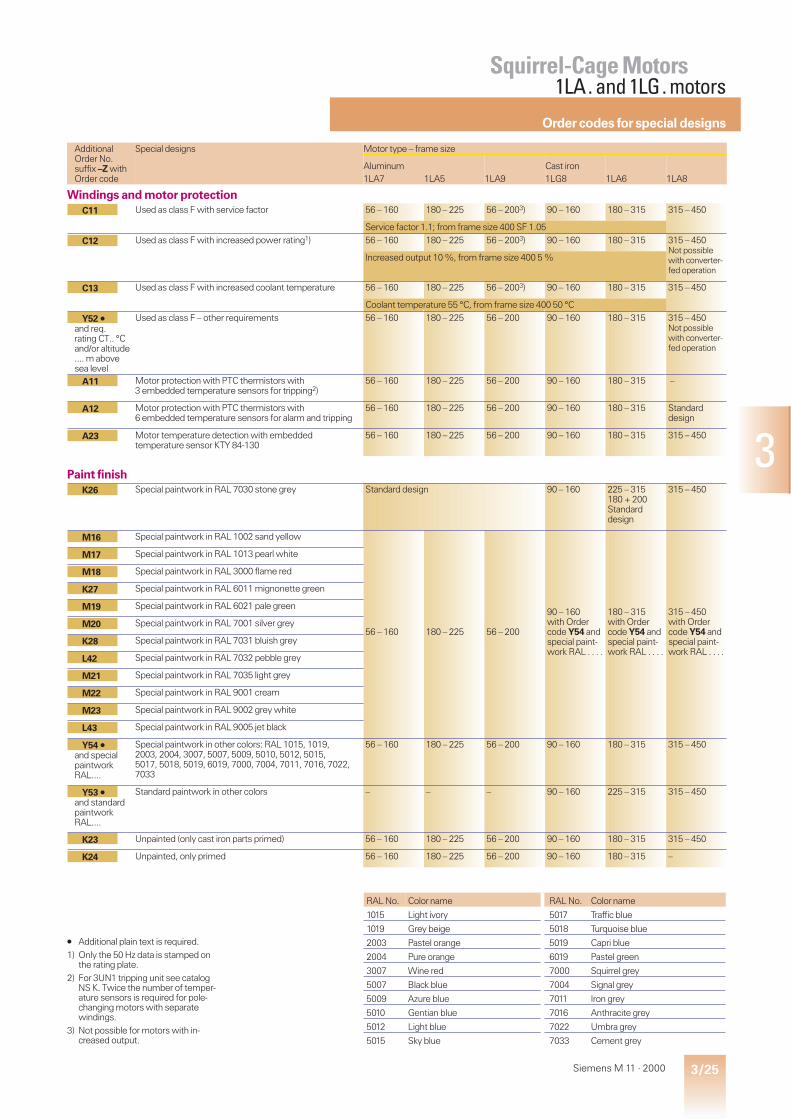
3/25Siemens M 11 · 2000
3
AdditionalOrder No.suffix –Z withOrder code
Special designs Motor type – frame size
Aluminum1LA7 1LA5 1LA9
Cast iron1LG8 1LA6 1LA8
Windings and motor protectionC11 Used as class F with service factor 56 – 160 180 – 225 56 – 2003) 90 – 160 180 – 315 315 – 450
Service factor 1.1; from frame size 400 SF 1.05
C12 Used as class F with increased power rating1) 56 – 160 180 – 225 56 – 2003) 90 – 160 180 – 315 315 – 450Not possiblewith converter-fed operation
Increased output 10 %, from frame size 400 5 %
C13 Used as class F with increased coolant temperature 56 – 160 180 – 225 56 – 2003) 90 – 160 180 – 315 315 – 450
Coolant temperature 55 °C, from frame size 400 50 °C
Y52 Á
and req.rating CT.. °Cand/or altitude.... m abovesea level
Used as class F – other requirements 56 – 160 180 – 225 56 – 200 90 – 160 180 – 315 315 – 450Not possiblewith converter-fed operation
A11 Motor protection with PTC thermistors with3 embedded temperature sensors for tripping2)
56 – 160 180 – 225 56 – 200 90 – 160 180 – 315 –
A12 Motor protection with PTC thermistors with6 embedded temperature sensors for alarm and tripping
56 – 160 180 – 225 56 – 200 90 – 160 180 – 315 Standarddesign
A23 Motor temperature detection with embeddedtemperature sensor KTY 84-130
56 – 160 180 – 225 56 – 200 90 – 160 180 – 315 315 – 450
Paint finishK26 Special paintwork in RAL 7030 stone grey Standard design 90 – 160 225 – 315
180 + 200Standarddesign
315 – 450
M16 Special paintwork in RAL 1002 sand yellow
56 – 160 180 – 225 56 – 200
90 – 160with Ordercode Y54 andspecial paint-work RAL . . . .
180 – 315with Ordercode Y54 andspecial paint-work RAL . . . .
315 – 450with Ordercode Y54 andspecial paint-work RAL . . . .
M17 Special paintwork in RAL 1013 pearl white
M18 Special paintwork in RAL 3000 flame red
K27 Special paintwork in RAL 6011 mignonette green
M19 Special paintwork in RAL 6021 pale green
M20 Special paintwork in RAL 7001 silver grey
K28 Special paintwork in RAL 7031 bluish grey
L42 Special paintwork in RAL 7032 pebble grey
M21 Special paintwork in RAL 7035 light grey
M22 Special paintwork in RAL 9001 cream
M23 Special paintwork in RAL 9002 grey white
L43 Special paintwork in RAL 9005 jet black
Y54 Á
and specialpaintworkRAL....
Special paintwork in other colors: RAL 1015, 1019,2003, 2004, 3007, 5007, 5009, 5010, 5012, 5015,5017, 5018, 5019, 6019, 7000, 7004, 7011, 7016, 7022,7033
56 – 160 180 – 225 56 – 200 90 – 160 180 – 315 315 – 450
Y53 Á
and standardpaintworkRAL....
Standard paintwork in other colors – – – 90 – 160 225 – 315 315 – 450
K23 Unpainted (only cast iron parts primed) 56 – 160 180 – 225 56 – 200 90 – 160 180 – 315 315 – 450
K24 Unpainted, only primed 56 – 160 180 – 225 56 – 200 90 – 160 180 – 315 –
Á Additional plain text is required.1) Only the 50 Hz data is stamped on
the rating plate.2) For 3UN1 tripping unit see catalog
NS K. Twice the number of temper-ature sensors is required for pole-changing motors with separatewindings.
3) Not possible for motors with in-creased output.
RAL No. Color name RAL No. Color name
1015 Light ivory 5017 Traffic blue
1019 Grey beige 5018 Turquoise blue
2003 Pastel orange 5019 Capri blue
2004 Pure orange 6019 Pastel green
3007 Wine red 7000 Squirrel grey
5007 Black blue 7004 Signal grey
5009 Azure blue 7011 Iron grey
5010 Gentian blue 7016 Anthracite grey
5012 Light blue 7022 Umbra grey
5015 Sky blue 7033 Cement grey
Squirrel-Cage Motors1LA. and 1LG. motors
Ordercodes forspecial designs
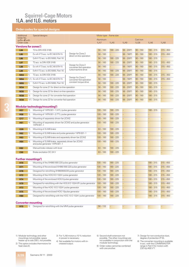
3/26 Siemens M 11 · 2000
3
AdditionalOrder No.suffix –Z withOrder code
Special designs Motor type – frame size
Aluminum1LA7 1LA5 1LA9
Cast iron1LG8 1LA6 1LA8
Versions for zones1)L84 T3 to DIN VDE 0165
ü
ï
ý
ï
þ
Design for Zone 2direct on-line operation
56 – 160 180 – 225 56 – 2004) 90 – 160 180 – 315 315 – 450
L85 Ex nA II T3 acc. to IEC 60 079-15 56 – 160 – 56 – 1604) 90 – 160 180 – 315 315 – 450
L86 ExN II T3 acc. to BS 5000, Part 16 56 – 160 180 – 225 56 – 2004) 90 – 160 180 – 315 –
L87 T3 acc. to DIN VDE 0165ü
ï
ý
ï
þ
Design for Zone 2converter-fed operationturbomachine drive
56 – 160 180 – 225 56 – 2004) 90 – 160 180 – 315 315 – 450
L88 2) Ex nA II T3 acc. to IEC 60 079-15 56 – 160 – 56 – 1604) 90 – 160 180 – 315 315 – 450
L89 2) ExN II T3 acc. to BS 5000, Part 16 56 – 160 180 – 225 56 – 2004) 90 – 160 180 – 315 –
M03 3) T3 acc. to DIN VDE 0165ü
ï
ý
ï
þ
Design for Zone 2converter-fed operationconstant torque drive
56 – 160 180 – 225 56 – 2004) 90 – 160 180 – 315 315 – 450
M04 2) 3) Ex nA II T3 acc. to IEC 60 079-15 56 – 160 – 56 – 1604) 90 – 160 180 – 315 315 – 450
M05 2) ExN II T3 acc. to BS 5000, Part 16 56 – 160 180 – 225 56 – 2004) 90 – 160 180 – 315 –
M34 Design for zone 21 for direct on-line operation 56 – 160 180 – 225 56 – 2004) 90 – 160 180 – 315 –
M35 7) Design for zone 22 for direct on-line operation 56 – 160 180 – 225 56 – 2004) 90 – 160 180 – 315 –
M38 2) Design for zone 21 for converter-fed operation 56 – 160 180 – 225 56 – 2004) 90 – 160 180 – 315 –
M39 2)7) Design for zone 22 for converter-fed operation 56 – 160 180 – 225 56 – 2004) 90 – 160 180 – 315 –
Modular technology/mounting5)H57 6) Mounting of 1XP8 001–1 (HTL) pulse generator 100 – 160 180 – 225 – – 180 – 315 –
H58 6) Mounting of 1XP8 001–2 (TTL) pulse generator 100 – 160 180 – 225 – – –
G17 6) Mounting of separately driven fan 2CW2 100 – 160 180 – 225 – – – –
H61 6) Mounting of separately driven fan 2CW2 and pulse generator1XP8 001–1
100 – 160 180 – 225 – – – –
G26 6) Mounting of 2LM8 brake 63 – 160 180 – 225 – – – –
H62 6) Mounting of 2LM8 brake and pulse generator 1XP8 001–1 100 – 160 180 – 225 – – – –
H63 6) Mounting of 2LM8 brake and separately driven fan 2CW2 100 – 160 180 – 225 – – – –
H64 6) Mounting of 2LM8 brake, separately driven fan 2CW2and pulse generator 1XP8 001–1
100 – 160 180 – 225 – – – –
K82 Manual brake release with lever 63 – 160 180 – 225 – – – –
C00 Brake excitation DC 24 V 63 – 160 180 – 225 – – – –
Further mountings5)H70 Mounting of the XH860 900 220 pulse generator 100 – 160 180 – 225 – – 180 – 315 315 – 450
H71 Mounting of the enclosed XH860 900 220 pulse generator 100 – 160 180 – 225 – – 180 – 315 315 – 450
H78 Designed for retrofitting XH860900220 pulse generator 100 – 160 180 – 225 – – 180 – 315 315 – 450
H72 Mounting of the HOG 9 D 1024 I pulse generator 100 – 160 180 – 225 – – 180 – 315 315 – 450
H74 Mounting of the enclosed HOG 9 pulse generator 100 – 160 180 – 225 – – 180 – 315 315 – 450
H79 Designed for retrofitting with the HOG 9 D 1024 KR I pulse generator 100 – 160 180 – 225 – – 180 – 315 315 – 450
H73 Mounting of the HOG 10 D 1024 I pulse generator 100 – 160 180 – 225 – – 180 – 315 315 – 450
H75 Mounting of the enclosed HOG 10pulse generator 100 – 160 180 – 225 – – 180 – 315 315 – 450
H80 Designed for retrofitting with the HOG 10 D 1024 I pulse generator 100 – 160 180 – 225 – – 180 – 315 315 – 450
Converter mountingH15 8) Designed for retrofitting with the MMI pulse generator 56 – 132 – – – – –
1) Modular technology and othermountings not possible; spaceheater up to size 200 L not possible.
2) This option includes thermistors forheat class B.
3) For 1LA8 motors a 10 % reductionin power is necessary.
4) Not available for motors with in-creased output.
5) Second shaft extension notpossible. The other mountings arenot available in conjunction with themodular technology.
6) Order codes cannot be combinedwith one another.
7) Design for non-conductive dust,degree of protection IP 55.
8) The converter mounting is availablein acc. with the COMBIMASTERrange in Part 4 for motors with230 Vd/400 V*.
Squirrel-Cage Motors1LA. and 1LG. motors
Ordercodes forspecial designs

3/27Siemens M 11 · 2000
3
Squirrel-Cage Motors1LA. and 1LG. motors
AdditionalOrder No.suffix –Z withOrder code
Special designs Motor type – frame size
Aluminum1LA7 1LA5 1LA9
Cast iron1LG8 1LA6 1LA8
Mechanical featuresK06 Two-part board of the terminal box – – – – 225 – 315 315 – 355
for BG 400 &450 standarddesign
K09 Side-mounted terminal box, right(when viewed in the drive end side)
80 – 160 180 – 225 80 – 200 90 – 160 180 – 315 Standarddesign
K10 Side-mounted terminal box, left(when viewed in the drive end side)
80 – 160 180 – 225 80 – 200 90 – 160 180 – 315 315 – 450
K83 Terminal box rotated 90°, entry from drive-end 56 – 160 180 – 225 56 – 200 90 – 160 180 – 315 315 – 450
K84 Terminal box rotated 90°, entry from non-drive end 56 – 160 180 – 225 56 – 200 90 – 160 180 – 315 315 – 450
K85 Terminal box rotated 180° 56 – 160 180 – 225 56 – 200 90 – 160 180 – 315 315 – 450
D40 Canadian standards (CSA)1) 56 – 160 180 – 200 56 – 200 90 – 160 180 – 315 315 – 450
with voltage code 9 and Order code for voltage and frequency
K01 Vibration severity grade R 56 – 160 180 – 225 56 – 200 90 – 160 180 – 315 315 – 400
for pole-changing on request
K16 Second standard shaft-end2) 56 – 160 180 – 225 56 – 200 90 – 160 180 – 315 315 – 450
K17 Drive-end seal for flange-mounting motors3) 56 – 160 180 – 225 56 – 200 90 – 160 180 – 315 –
K20 Bearings for increased cantilever forces4) 100 – 160 180 – 225 100 – 200 – 180 – 315 315 – 355
K40 Regreasing device 100 – 160 180 – 225 100 – 200* 160 180 – 250,from BG 280 standard design
L04 Locating bearing at non-drive end 56 – 132 – 56 – 132 90 – 100 – –
K94 Locating bearing at drive end 56 – 160 180 – 225 56 – 200 90 – 160 180 – 225 –
L27 Insulated bearing cartridge – – – – 225 – 315 Standardfor duty atSIMOVERTMASTER-DRIVES
L13 External earthing 56 – 160 180 – 225 56 – 200 90 – 160 Standarddesign
K30 VIK design5) 56 – 160 – 56 – 160 90 – 160 180 – 225 315 – 355
K31 Extra rating plate, loose 56 – 160 180 – 225 56 – 200 90 – 160 180 – 225 315 – 450
Y82 Á
for purch-asers’ data
Extra rating plate 56 – 160 180 – 225 56 – 200 90 – 160 180 – 225 315 – 450
K37 Low-noise design for 2-pole motors withclockwise direction of rotation6)
132 – 160 180 – 225 180 – 200 132 – 160 180 – 315 315,for 355 – 450standarddesign
K38 Low-noise design for 2-pole motors withanticlockwise direction of rotation6)
132 – 160 180 – 225 180 – 200 132 – 160 180 – 315 315 – 450
K45 Anti-condensation heater for 230 V 56 – 160 180 – 225 56 – 200 90 – 160 180 – 315 315 – 450
K46 Anti-condensation heater for 115 V 56 – 160 180 – 225 56 – 200 90 – 160 180 – 315 315 – 450
L99 Wire-lattice pallet 56 – 160 180 56 – 180 – 180 –
Safety and commissioning notes/certificationB00 Without S&C note
Customer’s declaration of renouncement required56 – 160 180 – 225 56 – 200 – 180 – 200 –
B01 With one S&C note per grid crate 56 – 160 180 56 – 180 – 180 –
B02 Factory test in accordance with EN 10 204 2.3 56 – 160 180 – 225 56 – 200 90 – 160 180 – 315 Standarddesign
Á Additional plain text is required.1) The rated voltage is included on the
rating plate. Separately driven fanand brake are not CSA certified.
2) Vertically mounted for 1LA6 onrequest, low-noise design not avail-able,
3) Not available for type of construc-tion IM V 3, 1LA6 motors only4 to 8-pole.
4) Not available for:2-pole 1LA6 motors, frame size315 L, vertically mounted;2-pole 1LA8 motors, frame sizes315 to 355;1LA8 motors, vertically mounted.Vibration severity grade Ron request for 1LA6 motors,frame sizes BG 225 M or larger.
5) Low-noise design is additionallyrequired for motors with framesizes 315 S to 315 L. Please notethe rated-output assignment andthe dimensions of 1LA8 motors.The terminal box of 2- and 4-pole1LA8 357 motors can’t be rotatedby 4 x 90°.
6) 1LA6 motors are up to 80 mmlonger than the standard design.A second shaft extension cannot bemounted.
* From October 2000.Not possible for 1LA9 134-6.
Ordercodes forspecial designs
3/28 Siemens M 11 · 2000
3
Squirrel-Cage Motors
Notes

5/1Siemens M 11 · 2000
5
Selection and ordering data5/2 2-pole, 50 Hz, temperature classes T1 to T35/3 4-pole, 50 Hz, temperature classes T1 to T35/4 6-pole, 50 Hz, temperature classes T1 to T3
5/5 Special designs
Squirrel-Cage MotorsIncreased Safety
EEx e II Type of Protection
1MA motorsIncreased Safety
Frame sizes 63 to 355Output range 0.12 to 400 kWTemperature class T1 to T3Class F Utilization according to class B

5/2 Siemens M 11 · 2000
5
Ratedoutput
Tem-pera-tureclasses
Framesize
Order No.
For Order No.suffixesfor voltage andtype of constr.seetable below
Performance at rated output Locked Locked Break- tE-time Torque Mo-mentofinertiaJ
Weight
Type ofconstr.IM B 3
approx.
Ratedspeed
Effi-ciencyh
1)
Powerfactorp.f.
Ratedcurrentat400 V
Ratedtorque
rotortorque
rotorcurrent
downtorque for tem-
peraturerises
class charac-teris-ticacc. topages2/10 to2/13
For direct-online starting inmultiples of ratedtorque current torque T1
T2T3
kW rpm % A Nm s s CL kg m2 kg
3000 rpm, 2-pole, 50 Hz0.180.25
T1–T3T1–T3
63 1MA7 060–2BA . .1MA7 063–2BA . .
28102810
6667
0.740.78
0.550.71
0.610.85
2.32.2
4.44.3
2.32.3
3016
2714
1616
1 0.000180.00023
3.54.0
0.370.55
T1–T3T1–T3
71 1MA7 070–2BA . .1MA7 073–2BA . .
26952765
6671
0.810.80
1.031.43
1.31.9
2.33.0
4.05.0
2.12.6
2617
1511
1616
1 0.000350.00045
5.47.0
0.751.1
T1–T3T1–T3
80 1MA7 080–2BA . .1MA7 083–2BA . .
28452855
7379
0.850.85
1.812.5
2.53.7
2.52.8
6.26.4
2.73.0
1312
1110
1616
9 0.000850.0011
8.610.3
1.31.85
T1–T3T1–T3
90 S90 L
1MA7 090–2BA . .1MA7 096–2BA . .
28502865
7881
0.880.88
2.93.9
4.46.2
2.62.8
6.26.8
2.82.8
1210
116
1616
2 0.00150.002
13.316.1
2.5 T1–T3 100 L 1MA7 106–2BA. . 2865 82 0.86 5.3 8.3 2.6 7.4 2.8 9 8 16 2 0.0038 213.3 T1–T3 112 M 1MA7 113–2BB . . 2875 84 0.89 6.7 11 2.1 6.6 2.3 10 9 13 11 0.0055 254.65.56.5
T1–T3T3T1,T2
132 S 1MA7 130–2BB . .1MA7 131–2BB . .2)
289529202890
848585
0.880.890.91
9.310.712.6
151821
1.91.92.2
6.17.86.6
2.52.32.7
111210
11117
131313
5 0.0160.0210.021
435050
7.59.5
101312.516
T3T1,T2T3T1,T2T3T1,T2
160 M
160 L
1MA7 163–2BB . .2)
1MA7 164–2BB . .2)
1MA7 166–2BB . .2)
294029102925288529402910
868687878987
0.850.880.910.920.930.93
15.318.619.124.523.030.0
243133434153
2.21.72.11.62.31.8
7.66.17.45.77.55.8
3.12.42.92.23.02.3
8151816235
17–8
–9
–
131313131313
55555
11
0.0340.0340.040.040.0520.052
717182829999
1519
T3T1, T2
180 M 1MA6 183–2BC . . 29602950
93.591.5
0.870.89
26.533.5
4962
2.01.6
8.06.3
3.32.6
2318
12 1010
22 0.077 165
20252431
T3T1, T2T3T1, T2
200 L 1MA6 206–2BC . .
1MA6 207–2BC . .
2965295029652950
91.591.592.592.5
0.870.880.880.89
3644.54354
648177
100
1.91.52.01.5
6.75.46.95.4
2.92.33.02.3
27223425
17
16
10101010
22 0.14
0.16
230
250
2838
T3T1, T2
225 M 1MA6 223–2BC . .1MA6 223–2AC . .
29702970
93.693.9
0.90.89
51693)
90122
1.81.8
6.47.0
2.72.7
3016
13 1010
22 0.24 310
3647
T3T1, T2
250 M 1MA6 253–2BC . .1MA6 253–2AC . .
29752975
93.593.9
0.910.9
6485
116151
1.51.5
6.66.5
2.72.7
3018
11 1010
22 0.45 415
47645876
T3T1, T2T3T1, T2
280 S280 S280 M280 M
1MA6 280–2BD . .1MA6 280–2AD . .1MA6 283–2BD . .1MA6 283–2AD . .
2983298029822978
94.594.394.794.8
0.90.890.910.9
84115104134
150205186244
1.51.51.51.5
7.17.87.27.5
2.92.92.82.8
30192715
23
11
7777
27 0.79
0.92
570
610
689580
112
T3T1, T2T3T1, T2
315 S315 S315 M315 M
1MA6 310–2BD . .1MA6 310–2AD . .1MA6 313–2BD . .1MA6 313–2AD . .
2985298529852985
94.094.694.894.8
0.910.90.910.91
1201691421983)
218304256358
1.41.51.61.4
7.17.37.07.5
2.82.92.82.7
50304021
21
19
7777
27 1.3
1.5
790
850
100135125165
T3T1, T2T3T1, T2
315 L 1MA6 316–2BD . .1MA6 316–2AD . .1MA6 317–2BD . .1MA6 317–2AD . .
2984298429852986
94.995.295.595.7
0.920.910.910.91
174234214280
320432400528
1.41.61.51.8
6.87.47.39.3
2.72.92.52.9
4017307 C
11
7 C
7777
27 1.8
2.3
990
1100
150200190255
T3T1, T2T3T1, T2
315 1MA8 315–2BD . .1MA8 315–2AD . .1MA8 317–2BD . .1MA8 317–2AD . .
2982298029822982
95.996.296.596.7
0.920.920.920.92
260345325435
480640608816
1.11.01.21.2
6.46.16.77.0
2.62.52.72.8
18
13
13
10
7777
30 2.7
3.3
1300
1500
220300250335300400
T3T1, T2T3T1, T2T3T1, T2
355 1MA8 353–2BE . .1MA8 353–2AE . .1MA8 355–2BE . .1MA8 355–2AE . .1MA8 357–2BE . .1MA8 357–2AE . .
298229822985298529852982
96.396.696.596.896.896.9
0.920.910.920.910.920.92
3755204305804)5)510680
704960800
1070960
1280
0.91.01.01.01.01.0
6.16.46.46.56.56.1
2.52.72.62.72.62.5
14
15
15
11
10
11
555555
30 4.8
5.3
6.4
1900
2000
2200
V Utilization acc. to class F. C VIK not possible. s With axial-flow fan for clockwise rotation.
Voltage code „9“ for other voltages and/or frequencies.Order codes must be specified in this case.Certification costs may be incurred.
There may be changes to the motor types which have not yet beenapproved by the PTB (Physikalisch-Technische Bundesanstalt).
See page 5/3 for footnotes.
Temperature rises T1 to T3,Degree of protection IP 55, temperature class F
Squirrel-Cage MotorsIncreased Safety×EEx e II Type of Protection
Selection and ordering data
Order No.suffixes
Motor type Penultimate position: Voltage code Last position: Type of construction code50 Hz IM B 3 extra charge230 Vd 400 Vd/ 500 V* 500 Vd IM B 5 IM V 1 IM B 14 IM B 14 IM B 35400 V* 690 V* with
canopywithstandardflange
withcustomflange
dconnections require overload protectionwith a phase-failure device.
1MA7 060 to 1MA7 0961MA7 106 to 1MA7 166
11
68)6
39)3
–5
00
11
44
22
33
66
1MA6 183 to 1MA6 3131MA6 316 to 1MA6 317
1–
66
33
55
00
1–
44
––
––
66
1MA8 315 to 1MA8 357 – 66) 37) on request 0 – 4 – – 6
5/3Siemens M 11 · 2000
5
Ratedoutput
Tem-pera-tureclasses
Framesize
Order No.
For Order No.suffixesfor voltage andtype of constr.see tableon page 5/2
Performance at rated output Locked Locked Break- tE-time Torque Mo-mentofinertiaJ
Weight
Type ofconstr.IM B 3
approx.
Ratedspeed
Effi-ciencyh
1)
Powerfactorp.f.
Ratedcurrentat400 V
Ratedtorque
rotortorque
rotorcurrent
downtorque for tem-
peraturerises
class charac-teris-ticacc. topages2/10 to2/13
For direct-online starting inmultiples of ratedtorque current torque T1
T2T3
kW rpm % A Nm s s CL kg m2 kg
1500 rpm, 4-pole, 50 Hz0.120.18
T1–T3T1–T3
63 1MA7 060–4BB . .1MA7 063–4BB . .
13751330
5557
0.660.75
0.520.62
0.831.3
1.91.9
2.62.7
1.91.9
3530
3025
1313
12 0.00030.0004
3.54.0
0.250.37
T1–T3T3
71 1MA7 070–4BB . .1MA7 073–4BB . .
13101355
6067
0.770.74
0.801.10
1.82.6
1.91.9
3.13.7
1.92.1
5035
4029
1313
12 0.00060.00083
5.26.4
0.550.75
T1–T3T1–T3
80 1MA7 080–4BA . .1MA7 083–4BA . .
13901395
7373
0.730.75
1.592.05
3.85.1
2.42.6
4.64.8
2.52.6
2419
2116
1616
3 0.00150.0018
8.49.8
11.35
T1–T3T1–T3
90 S90 L
1MA7 090–4BA . .1MA7 096–4BA . .
14201415
7778
0.780.81
2.53.1
6.79.1
2.22.3
5.55.9
2.52.5
1615
1413
1616
3 0.00280.0035
12.716
22.5
T1–T3T1–T3
100 L 1MA7 106–4BA . .1MA7 107–4BA . .
14201415
8081
0.810.83
4.55.5
1417
2.52.6
6.46.4
2.72.7
1312
1110
1616
3 0.00480.0058
2224
3.6 T1–T3 112 M 1MA7 113–4BA . . 1435 85 0.83 7.5 24 2.6 7.2 2.9 10 9 16 3 0.011 2956.8
T1–T3T1–T3
132 S132 M
1MA7 130–4BA . .1MA7 133–4BA . .
14451465
8687
0.820.82
10.414.0
3344
2.73.0
6.67.6
3.23.6
1011
99
1616
9 0.0210.027
3953
1013.5
T1–T3T1–T3
160 M160 L
1MA7 163–4BB . .1MA7 166–4BB . .
14551465
8889
0.870.84
19.727
6688
2.32.4
6.56.8
2.73.0
1718
109
1313
9 0.0520.057
7390
151717.520
T3T1, T2T3T1, T2
180 M180 M180 L180 L
1MA6 183–4BC . .
1MA6 186–4BC . .
1470146514701465
91.39191.791.6
0.810.820.820.83
29.53333.5383)
97111114130
1.81.61.81.6
6.65.86.96,
2.92.43.02.6
15131714
15
15
10101010
22 0.13
0.15
165
180
2427
T3T1, T2
200 L 1MA6 207–4BC . . 14751470
92.292.0
0.830.84
4550
155175
2.11.8
7.06.2
3.02.6
1614
8 1010
22 0.24 240
30333640
T3T1, T2T3T1, T2
225 S225 S225 M225 M
1MA6 220–4BC . .
1MA6 223–4BC . .
1481148014841480
93.393.193.893.6
0.830.840.840.85
59643)703)773)
193213232258
1.61.41.71.5
6.76.26.96.2
2.72.52.82.5
13111210
13
12
10101010
22 0.44
0.52
300
330
4450
T3T1, T2
250 M 1MA6 253–4BC . . 14851485
9493.8
0.850.86
8394
283322
1.71.5
7.36.4
2.52.1
1815
11 1010
22 0.79 435
58687080
T3T1, T2T3T1, T2
280 S280 S280 M280 M
1MA6 280–4BC . .
1MA6 283–4BC . .
1488148514881485
94.694.594.894.8
0.840.850.850.87
1111311301503)
372437449514
1.71.51.71.5
6.35.37.06.0
2.52.12.52.2
30232620
7 C
6 C
10101010
22 1.4
1.6
610
660
84100100120
T3T1, T2T3T1, T2
315 S315 S315 M315 M
1MA6 310–4BD . .
1MA6 313–4BD . .
1492149014921488
95.495.395.895.7
0.840.850.850.86
1581881852223)
538641640770
1.71.41.61.3
7.76.57.26.0
2.82.42.52.1
28242924
8
7 C
7777
28 2.2
2.7
830
910
115135135165
T3T1, T2T3T1, T2
315 L 1MA6 316–4BD . .
1MA6 317–4BD . .
1490148814921485
95.695.595.895.8
0.860.870.860.87
214248245305
740868868
1061
1.71.41.71.5
7.56.47.86.3
2.52.12.82.3
28212617
5 C
7
7777
28 3.2
4.2
1060
1200
170200215245
T3T1, T2T3T1, T2
315 1MA8 315–4BD . .
1MA8 317–4BD . .
1490148614901486
96.296.196.596.4
0.860.870.870.88
310365390440
1090129013801570
1.31.11.41.2
6.65.66.65.8
2.72.32.72.4
23
24
9
9
7777
31 3.6
4.4
1300
1500
240275275315350400
T3T1, T2T3T1, T2T3T1, T2
355 1MA8 353–4BE . .
1MA8 355–4BE . .
1MA8 357–4BE . .
149014881490148814901488
96.596.496.796.696.996.8
0.880.890.880.880.880.89
4304854)4904)5604)620710
154017601760202022402570
0.90.80.90.81.00.9
6.35.56.45.66.55.7
2.52.22.62.32.62.3
27
28
26
11
12
11
555555
34 6.1
6.8
8.5
1900
2000
2200
CVIK not possible.
1) Referring to 75 °C.2) Separate designs for T1, T2 and T3
with voltage code “9”.3) Parallel feeders required for 230 V
supply.
4) Parallel feeders required for 400 Vsupply.
5) Parallel feeders required for 500 Vsupply.
6) Please enquire about the ratedvoltage range for 1MA8.
7) Please enquire about 2-polemotors.
8) Not available for 1MA7 06.9) 500 V* design not available for
1MA7 060-4.
Temperature rises T1 to T3,Degree of protection IP 55, temperature class F
Squirrel-Cage MotorsIncreased Safety×EEx e II Type of Protection
Selection and ordering data
5/4 Siemens M 11 · 2000
5
Ratedoutput
Tem-pera-tureclasses
Framesize
Order No.
For Order No.suffixesfor voltage andtype of constr.seetable below
Performance at rated output Locked Locked Break- tE-time Torque Mo-mentofinertiaJ
Weight
Type ofconstr.IM B 3
approx.
Ratedspeed
Effi-ciencyh
1)
Powerfactorp.f.
Ratedcurrentat400 V
Ratedtorque
rotortorque
rotorcurrent
downtorque for tem-
peraturerises
class charac-teris-ticacc. topages2/10 to2/13
For direct-online starting inmultiples of ratedtorque current torque T1
T2T3
kW rpm % A Nm s s CL kg m2 kg
1000 rpm, 6-pole, 50 Hz0.25 T1–T3 71 1MA7 073–6BA . . 850 63 0.72 0.81 2.8 2.2 3.0 2.1 130 70 16 6 0.0009 6.70.370.55
T1–T3T1–T3
80 1MA7 080–6BA . .1MA7 083–6BA . .
920930
6869
0.700.67
1.141.75
3.65.6
2.32.4
3.64.0
2.42.4
6034
5527
1616
6 0.00150.0025
8.312.5
0.650.95
T1–T3T1–T3
90 S90 L
1MA7 090–6BA . .1MA7 096–6BA . .
915915
7072
0.750.75
1.82.6
6.89.9
2.32.3
3.94.1
2.42.4
3522
3019
1616
6 0.00280.0038
12.515.7
1.3 T1–T3 100 L 1MA7 106–6BA . . 935 77 0.73 3.35 13 2.4 4.8 2.5 26 26 16 6 0.0063 221.9 T1–T3 112 M 1MA7 113–6BB . . 940 79 0.76 4.7 19 2.3 5.0 2.5 19 16 13 6 0.011 252.63.54.8
T1–T3T1–T3T1–T3
132 S132 M132 M
1MA7 130–6BB . .1MA7 133–6BB . .1MA7 134–6BB . .
945955950
798183
0.750.720.76
6.58.9
11.4
263548
1.82.32.4
4.45.15.6
2.42.82.8
211613
181311
131313
6 0.0150.0190.025
384351
6.69.7
T1–T3T1–T3
160 M160 L
1MA7 163–6BB . .1MA7 166–6BB . .
960965
8588
0.760.76
14.921.0
6596
2.72.8
6.57.7
3.12.2
1815
98
1313
6 0.0410.055
7399
13.2 T1–T3 180 L 1MA6 186–6BC . . 976 89.8 0.79 27.5 129 1.6 5.4 2.5 27 27 10 22 0.20 17016.520
T1–T3T1–T3
200 L 1MA6 206–6BC . .1MA6 207–6BC . .
980980
90.891.3
0.820.82
32.539
161195
1.71.7
5.85.9
2.62.6
2417
2415
1010
22 0.290.33
220235
27 T1–T3 225 M 1MA6 223–6BC . . 980 92.5 0.82 54 263 1.6 5.6 2.5 15 15 10 22 0.57 30533 T1–T3 250 M 1MA6 253–6BC . . 985 93 0.83 66 320 1.6 5.3 2.4 16 16 10 22 0.89 410404650
T1–T3T3T1, T2
280 S280 M280 M
1MA6 280–6BC . .1MA6 283–6BC . .
990988987
93.393.593.3
0.850.860.86
778696
386445484
1.51.61.5
6.26.55.8
2.62.52.3
13
14
1312
101010
22 1.31.5
540580
64687682
T3T1, T2T3T1, T2
315 S315 S315 M315 M
1MA6 310–6BC . .
1MA6 313–6BC . .
991990991990
94.394.294.694.5
0.840.850.840.84
124131146158
617656732791
1.71.61.71.6
6.25.96.45.9
2.52.32.52.3
22
18
14
8
10101010
22 2.4
2.9
770
830
9298
110120125135
T3T1, T2T3T1, T2T3T1, T2
315 L 1MA6 316–6BC . .
1MA6 317–6BC . .
1MA6 318–6BC . .
991990991990991990
9594.895.29595.295.0
0.850.850.840.850.860.86
172185210230220 V
240 V
887945
1060116012101300
1.71.61.71.61.61.5
6.56.16.86.27.06.5
2.52.32.52.32.52.3
20
16
17
9
6 C
6 C
101010101010
22 3.5
4.3
4.9
970
1060
1100
160175200215
T3T1, T2T3T1, T2
315 1MA8 315–6BD . .
1MA8 317–6BD . .
991990991990
95.995.896.196.0
0.860.870.870.88
290315360380
1540169019302070
1.31.21.41.3
6.66.16.46.0
2.62.42.72.5
20
20
16
15
7777
32 6.0
7.3
1300
1500
250275315340
T3T1, T2T3T1, T2
355 1MA8 355–6BD . .
1MA8 357–6BD . .
994993995994
96.496.396.796.6
0.860.870.860.86
4554952)5702)6102)
2400264030203270
1.31.21.41.3
6.56.06.96.5
2.52.32.62.4
22
23
14
14
7777
33 13
16
1900
2200
V Certified for rated voltage of 400 V only. C VIK not possible.
1) Referring to 75 °C. 2) Parallel feeders required for 400 Vsupply.
3) Please inquire about the ratedvoltage range 1MA8.
Motor type Penultimate position: Voltage code Last position: Type of construction code50 Hz IM B 3 extra charge230 Vd 400 Vd/ 500 V* 500 Vd IM B 5 IM V 1 IM B 14 IM B 14 IM B 35400 V* 690 V* with
canopywithstandardflange
withcustomflange
dconnections require overload protectionwith a phase-failure device.
1MA7 073 to 1MA7 0961MA7 106 to 1MA7 166
11
66
33
–5
00
11
44
22
33
66
1MA6 186 to 1MA6 3131MA6 316 to 1MA6 318
1–
66
33
55
00
1–
44
––
––
66
1MA8 315 to 1MA8 357 – 63) 3 on request 0 – 4 – – 6
Voltage code „9“ for other voltages and/or frequencies.Order codes must be specified in this case (see page 2/10).Certification costs may be incurred.
There may be changes to the motor types which have not yet beenapproved by the PTB (Physikalisch-Technische Bundesanstalt).
Temperature rises T1 to T3,Degree of protection IP 55, temperature class F
Squirrel-Cage MotorsIncreased Safety×EEx e II Type of Protection
Selection and ordering data
Order No.suffixes
5/5Siemens M 11 · 2000
5
Á Additional plain text required.1) For 3RN1 tripping unit see
Catalog NS K.
RAL No. Color name RAL No. Color name
1015 Light ivory 5017 Traffic blue
1019 Grey beige 5018 Turquoise blue
2003 Pastel orange 5019 Capri blue
2004 Pure orange 6019 Pastel green
3007 Wine red 7000 Squirrel grey
5007 Black blue 7004 Signal grey
5009 Azure blue 7011 Iron grey
5010 Gentian blue 7016 Anthracite grey
5012 Light blue 7022 Umbra grey
5015 Sky blue 7033 Cement grey
AdditionalOrder No.suffix –Z withOrder code
Special designs Motor type – frame sizes
1MA7 1MA6 1MA8
Windings and motor protectionY52 Á
and req. ratingCT.. °C and/oraltitude ... mabove sealevel
Used as class F – 63 – 160Request necessary.Certification costs may beincurred.
180 – 315Request necessary.Certification costs may beincurred.
–
A11 Motor protection with PTC thermistors with3 embedded temperature sensors for tripping1)
63 – 160 180 – 315 –
A12 Motor protection with PTC thermistors with6 embedded temperature sensors for alarm and tripping
63 – 160 180 – 315 Standard design
Paint finishK26 Special paintwork in RAL 7030 stone grey Standard design 180 – 315 315 – 355
M16 Special paintwork in RAL 1002 sand yellow
63 – 160 180 + 200
225 – 315withOrder codeY54 andspecialpaintworkRAL . . . .
315 – 355with Order code Y54 andspecial paintwork RAL . . . .
M17 Special paintwork in RAL 1013 pearl white
M18 Special paintwork in RAL 3000 flame red
K27 Special paintwork in RAL 6011 mignonette green
M19 Special paintwork in RAL 6021 pale green
M20 Special paintwork in RAL 7001 silver grey
K28 Special paintwork in RAL 7031 bluish grey
L42 Special paintwork in RAL 7032 pebble grey
M21 Special paintwork in RAL 7035 light grey
M22 Special paintwork in RAL 9001 cream
M23 Special paintwork in RAL 9002 grey white
L43 Special paintwork in RAL 9005 jet black
Y54 Á
and specialpaintworkRAL....
Special paintwork in other colors: RAL 1015, 1019,2003, 2004, 3007, 5007, 5009, 5010, 5012, 5015,5017, 5018, 5019, 6019, 7000, 7004, 7011, 7016, 7022,7033
63 – 160 180 – 315 315 – 355
Y53 Á
and specialpaintworkRAL....
Standard paintwork in other colors – 180 – 315 315 – 355
K23 Unpainted (only cast iron parts primed) 63 – 160 180 – 315 315 – 355
K24 Unpainted, only primed 63 – 160 180 + 200 –
Squirrel-Cage MotorsIncreased Safety×EEx e II Type of Protection
Order codes for special designs
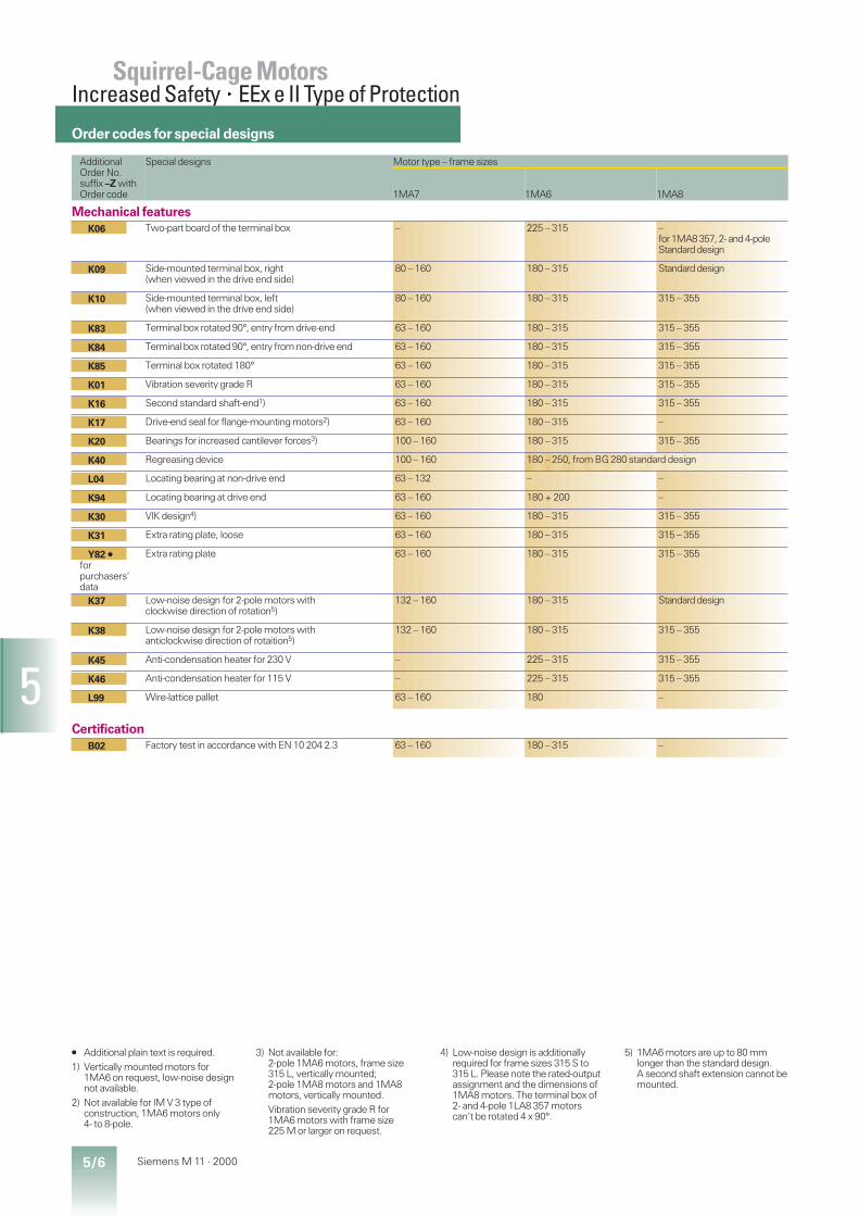
5/6 Siemens M 11 · 2000
5
AdditionalOrder No.suffix –Z withOrder code
Special designs Motor type – frame sizes
1MA7 1MA6 1MA8
Mechanical featuresK06 Two-part board of the terminal box – 225 – 315 –
for1MA8357,2- and4-poleStandarddesign
K09 Side-mounted terminal box, right(when viewed in the drive end side)
80 – 160 180 – 315 Standarddesign
K10 Side-mounted terminal box, left(when viewed in the drive end side)
80 – 160 180 – 315 315 – 355
K83 Terminal box rotated 90°, entry from drive-end 63 – 160 180 – 315 315 – 355
K84 Terminal box rotated 90°, entry from non-drive end 63 – 160 180 – 315 315 – 355
K85 Terminal box rotated 180° 63 – 160 180 – 315 315 – 355
K01 Vibration severity grade R 63 – 160 180 – 315 315 – 355
K16 Second standard shaft-end1) 63 – 160 180 – 315 315 – 355
K17 Drive-end seal for flange-mounting motors2) 63 – 160 180 – 315 –
K20 Bearings for increased cantilever forces3) 100 – 160 180 – 315 315 – 355
K40 Regreasing device 100 – 160 180 – 250, from BG 280 standard design
L04 Locating bearing at non-drive end 63 – 132 – –
K94 Locating bearing at drive end 63 – 160 180 + 200 –
K30 VIK design4) 63 – 160 180 – 315 315 – 355
K31 Extra rating plate, loose 63 – 160 180 – 315 315 – 355
Y82 Á
forpurchasers’data
Extra rating plate 63 – 160 180 – 315 315 – 355
K37 Low-noise design for 2-pole motors withclockwise direction of rotation5)
132 – 160 180 – 315 Standarddesign
K38 Low-noise design for 2-pole motors withanticlockwise direction of rotaition5)
132 – 160 180 – 315 315 – 355
K45 Anti-condensation heater for 230 V – 225 – 315 315 – 355
K46 Anti-condensation heater for 115 V – 225 – 315 315 – 355
L99 Wire-lattice pallet 63 – 160 180 –
CertificationB02 Factory test in accordance with EN 10 204 2.3 63 – 160 180 – 315 –
Á Additional plain text is required.1) Vertically mounted motors for
1MA6 on request, low-noise designnot available.
2) Not available for IM V 3 type ofconstruction, 1MA6 motors only4- to 8-pole.
3) Not available for:2-pole 1MA6 motors, frame size315 L, vertically mounted;2-pole 1MA8 motors and 1MA8motors, vertically mounted.Vibration severity grade R for1MA6 motors with frame size225 M or larger on request.
4) Low-noise design is additionallyrequired for frame sizes 315 S to315 L. Please note the rated-outputassignment and the dimensions of1MA8 motors. The terminal box of2- and 4-pole 1LA8 357 motorscan’t be rotated 4 x 90°.
5) 1MA6 motors are up to 80 mmlonger than the standard design.A second shaft extension cannot bemounted.
Squirrel-Cage MotorsIncreased Safety×EEx e II Type of Protection
Order codes for special designs

6/1Siemens M 11 · 2000
6
Selection and ordering data6/2 2-pole, 50 Hz, temperature classes T1 to T46/3 4-pole, 50 Hz, temperature classes T1 to T46/4 6-pole, 50 Hz, temperature classes T1 to T46/5 8-pole, 50 Hz, temperature classes T1 to T4
6/6 Special designs
Squirrel-Cage MotorsExplosion-Proof EnclosureEEx de IIC Type of Protection
1MJ motorsExplosion-proof enclosure
Frame sizes 71 to 450Output range 0.25 to 630 kWTemperature class T1 to T4Class F utilization according to class BSuitable for con-verter-fed operation ts > 0.1 ms at U£ 500 V
The motors are certified for the highest explosionclass IIC.

6/2 Siemens M 11 · 2000
6
Ratedoutput
Framesize
Order No. Performance at rated output Lo.-rotor Lo.rotor Breakdown Torque Mo-mentofinertiaJ
Weight
For Order No.suffixesfor voltage andtype of constr.seetable below
torque current torque class charac-teristicacc. topages2/10 to2/13
Ratedspeed
Effi-ciencyh
Powerfactorp.f.
Ratedcurrentat400 V
Ratedtorque For direct-online starting in
multiples of ratedType ofconstr.IM B 3
approx.
torque current torque
HP rpm % A Nm CL kg m2 kg
3000 rpm, 2-pole, 50 Hz0.370.55
71 M 1MJ6 070–2CA . .1MJ6 073–2CA . .
27502790
6771
0.810.81
0.981.38
1.31.9
2.32.3
4.35.3
2.32.3
1616
1 0.000350.00045
18.819.8
0.751.1
80 M 1MJ6 080–2CA . .1MJ6 083–2CA . .
28402835
7274
0.860.87
1.752.45
2.53.7
2.42.6
6.36.3
2.32.3
1616
1 0.000850.0011
2425.6
1.52.2
90 L 1MJ6 096–2CA . .1MJ6 097–2CA . .
28502860
7880
0.840.86
3.34.6
5.07.4
2.52.8
6.77.1
2.52.8
1616
2 0.00150.0020
32.335
3 100 L 1MJ6 106–2CA . . 2885 82 0.85 6.2 9.9 2.8 7.7 3.0 16 2 0.0038 44.44 112 M 1MJ6 113–2CA . . 2895 84 0.88 7.8 13 2.4 7.6 2.8 16 2 0.0055 56.35.57.5
132 S 1MJ6 130–2CA . .1MJ6 131–2CA . .
29102905
8384
0.860.89
11.114.5
1825
2.02.2
6.36.9
2.62.6
1616
2 0.0160.021
8085.5
111518.5
160 M160 M160 L
1MJ6 163–2CA . .1MJ6 164–2CA . .1MJ6 166–2CA . .
291529252925
858789
0.890.890.89
212833.5
364960
2.02.32.4
6.37.27.7
2.63.13.3
161616
2 0.0340.0400.052
125135160
22 180 M 1MJ6 183–2CA . . 2940 92 0.88 39 71 2.5 6.9 3.2 16 3 0.077 1753037
200 L 1MJ6 206–2CA . .1MJ6 207–2CA . .
29402945
92.392.8
0.890.90
5364
97120
2.42.4
6.57.7
2.82.8
1616
3 0.140.16
250270
45 225 M 1MJ6 223–2CB . . 2955 93.9 0.90 771) 145 2.3 6.9 2.7 13 14 0.24 33555 250 M 1MJ6 253–2CB . . 2965 94.0 0.91 93 177 2.1 6.9 2.8 13 14 0.45 4457590
280 S280 M
1MJ6 280–2CC . .1MJ6 283–2CC . .
29752975
94.795.1
0.900.91
1281501)
241289
1.92.0
7.07.0
2.72.7
1010
23 0.790.92
600640
110132
315 S315 M
1MJ6 310–2CC . .1MJ6 313–2CC . .
29802980
94.895.1
0.900.90
1862251)
353423
1.81.9
7.07.0
2.82.8
1010
23 1.31.5
840900
160200
315 M315 L
1MJ8 313–2AB . .1MJ8 316–2AB . .
29802980
95.796.2
0.880.89
280335
513641
2.22.3
6.96.9
2.52.6
1010
17 2.32.8
11001200
250315
355 M355 L
1MJ8 353–2AC . .1MJ8 356–2AC . .
29802980
96.296.6
0.890.89
4232)5302)
8011009
2.12.1
6.76.7
2.62.6
1313
17 3.54.2
17002000
355400
400 S400 M
1MJ8 400–2AD . .1MJ8 403–2AE . .
29862986
96.696.7
0.910.91
5852)6552)
11351279
0.90.85
6.56.6
2.82.9
75
15 5.26.0
25002800
450500560
450 M450 L450 L
1MJ8 453–2AE . .1MJ8 456–2AE . .1MJ8 457–2AE . .
299029902990
96.796.896.9
0.910.910.91
7402)8201)2)9201)2)
143715971789
0.80.80.8
6.66.56.5
2.92.82.8
555
15 91011
330037003700
V EEx de IIB type of protection.
Motor type Penultimate position: Voltage code Last position: Type of construction code50 Hz IM B 3 (extra charge)230 Vd/ 400 V* 400 Vd/ 500 V* 500 Vd IM B 5 IM V 1 IM B 14 IM B 14 IM B 35400 V* 690 V* with
canopywithstandardflange
withcustomflange
1MJ6 070 to 1MJ6 0971MJ6 106 to 1MJ6 1661MJ6 183 to 1MJ6 2071MJ6 223 to 1MJ6 313
111–
–––4
6666
3333
–55–
0000
1111
4444
2–––
33)–––
6666
1MJ8 313 to 1MJ8 3161MJ8 353 to 1MJ8 457
––
––
66
33
55
00
1–
44
––
––
66
Voltage code “9” for other voltages and/or frequencies.Order codes must be specified in this case.
1) Parallel feeders required for 400 Vsupply.
2) The motors have 2 terminal boxes,see Part 7.
3) Only up to 1MJ6 083.
Selection and ordering data
Order No.suffixes
Temperature classes T1 to T4,degree of protection IP 55,class F
Squirrel-Cage MotorsExplosion-Proof Enclosure×EEx de IIC Type of Protection
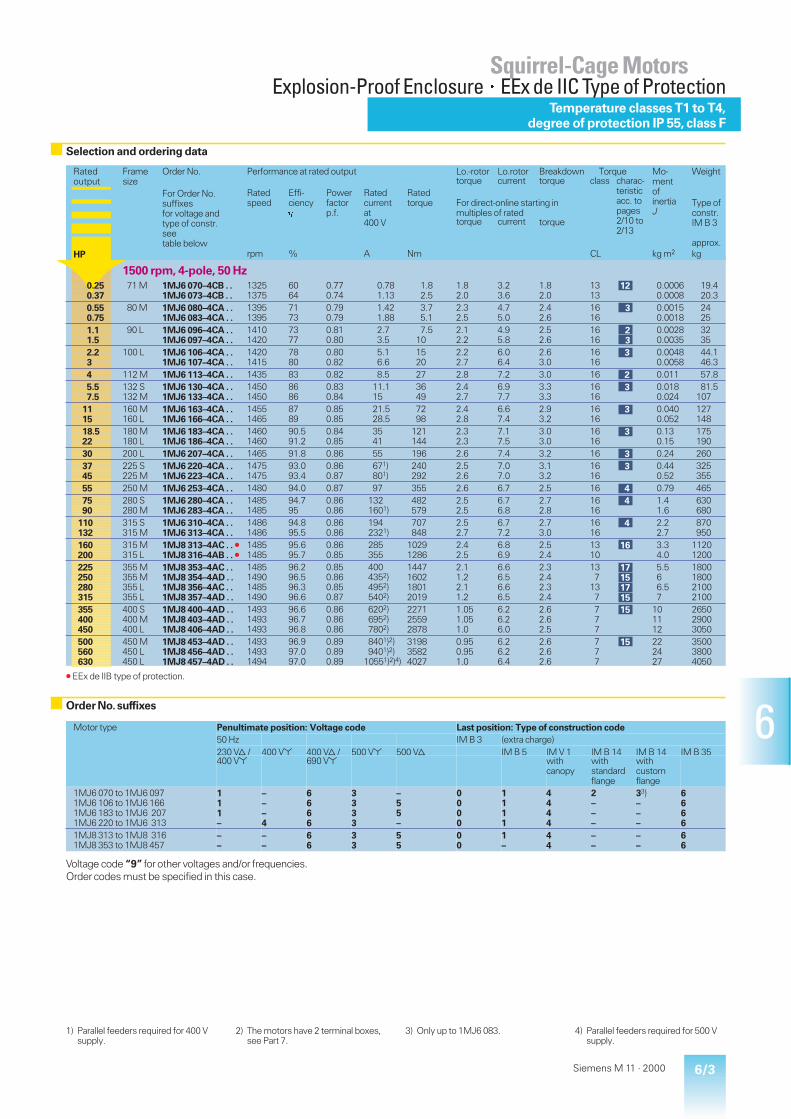
6/3Siemens M 11 · 2000
6Motor type Penultimate position: Voltage code Last position: Type of construction code50 Hz IM B 3 (extra charge)230 Vd/ 400 V* 400 Vd/ 500 V* 500 Vd IM B 5 IM V 1 IM B 14 IM B 14 IM B 35400 V* 690 V* with
canopywithstandardflange
withcustomflange
1MJ6 070 to 1MJ6 0971MJ6 106 to 1MJ6 1661MJ6 183 to 1MJ6 2071MJ6 220 to 1MJ6 313
111–
–––4
6666
3333
–55–
0000
1111
4444
2–––
33)–––
6666
1MJ8 313 to 1MJ8 3161MJ8 353 to 1MJ8 457
––
––
66
33
55
00
1–
44
––
––
66
Voltage code “9” for other voltages and/or frequencies.Order codes must be specified in this case.
1) Parallel feeders required for 400 Vsupply.
2) The motors have 2 terminal boxes,see Part 7.
3) Only up to 1MJ6 083. 4) Parallel feeders required for 500 Vsupply.
Ratedoutput
Framesize
Order No. Performance at rated output Lo.-rotor Lo.rotor Breakdown Torque Mo-mentofinertiaJ
Weight
For Order No.suffixesfor voltage andtype of constr.seetable below
torque current torque class charac-teristicacc. topages2/10 to2/13
Ratedspeed
Effi-ciencyh
Powerfactorp.f.
Ratedcurrentat400 V
Ratedtorque For direct-online starting in
multiples of ratedType ofconstr.IM B 3
approx.
torque current torque
HP rpm % A Nm CL kg m2 kg
1500 rpm, 4-pole, 50 Hz0.250.37
71 M 1MJ6 070–4CB . .1MJ6 073–4CB . .
13251375
6064
0.770.74
0.781.13
1.82.5
1.82.0
3.23.6
1.82.0
1313
12 0.00060.0008
19.420.3
0.550.75
80 M 1MJ6 080–4CA . .1MJ6 083–4CA . .
13951395
7173
0.790.79
1.421.88
3.75.1
2.32.5
4.75.0
2.42.6
1616
3 0.00150.0018
2425
1.11.5
90 L 1MJ6 096–4CA . .1MJ6 097–4CA . .
14101420
7377
0.810.80
2.73.5
7.510
2.12.2
4.95.8
2.52.6
1616
23
0.00280.0035
3235
2.23
100 L 1MJ6 106–4CA . .1MJ6 107–4CA . .
14201415
7880
0.800.82
5.16.6
1520
2.22.7
6.06.4
2.63.0
1616
3 0.00480.0058
44.146.3
4 112 M 1MJ6 113–4CA . . 1435 83 0.82 8.5 27 2.8 7.2 3.0 16 2 0.011 57.85.57.5
132 S132 M
1MJ6 130–4CA . .1MJ6 133–4CA . .
14501450
8686
0.830.84
11.115
3649
2.42.7
6.97.7
3.33.3
1616
3 0.0180.024
81.5107
1115
160 M160 L
1MJ6 163–4CA . .1MJ6 166–4CA . .
14551465
8789
0.850.85
21.528.5
7298
2.42.8
6.67.4
2.93.2
1616
3 0.0400.052
127148
18.522
180 M180 L
1MJ6 183–4CA . .1MJ6 186–4CA . .
14601460
90.591.2
0.840.85
3541
121144
2.32.3
7.17.5
3.03.0
1616
3 0.130.15
175190
30 200 L 1MJ6 207–4CA . . 1465 91.8 0.86 55 196 2.6 7.4 3.2 16 3 0.24 2603745
225 S225 M
1MJ6 220–4CA . .1MJ6 223–4CA . .
14751475
93.093.4
0.860.87
671)801)
240292
2.52.6
7.07.0
3.13.2
1616
3 0.440.52
325355
55 250 M 1MJ6 253–4CA . . 1480 94.0 0.87 97 355 2.6 6.7 2.5 16 4 0.79 4657590
280 S280 M
1MJ6 280–4CA . .1MJ6 283–4CA . .
14851485
94.795
0.860.86
1321601)
482579
2.52.5
6.76.8
2.72.8
1616
4 1.41.6
630680
110132
315 S315 M
1MJ6 310–4CA . .1MJ6 313–4CA . .
14861486
94.895.5
0.860.86
1942321)
707848
2.52.7
6.77.2
2.73.0
1616
4 2.22.7
870950
160200
315 M315 L
1MJ8 313–4AC . .1MJ8 316–4AB . .
14851485
95.695.7
0.860.85
285355
10291286
2.42.5
6.86.9
2.52.4
1310
16 3.34.0
11201200
225250280315
355 M355 M355 L355 L
1MJ8 353–4AC . .1MJ8 354–4AD . .1MJ8 356–4AC . .1MJ8 357–4AD . .
1485149014851490
96.296.596.396.6
0.850.860.850.87
4004352)4952)5402)
1447160218012019
2.11.22.11.2
6.66.56.66.5
2.32.42.32.4
137
137
17151715
5.566.57
1800180021002100
355400450
400 S400 M400 L
1MJ8 400–4AD . .1MJ8 403–4AD . .1MJ8 406–4AD . .
149314931493
96.696.796.8
0.860.860.86
6202)6952)7802)
227125592878
1.051.051.0
6.26.26.0
2.62.62.5
777
15 101112
265029003050
500560630
450 M450 L450 L
1MJ8 453–4AD . .1MJ8 456–4AD . .1MJ8 457–4AD . .
149314931494
96.997.097.0
0.890.890.89
8401)2)9401)2)
10551)2)4)
319835824027
0.950.951.0
6.26.26.4
2.62.62.6
777
15 222427
350038004050
V EEx de IIB type of protection.
Temperature classes T1 to T4,degree of protection IP 55,class F
Squirrel-Cage MotorsExplosion-Proof Enclosure×EEx de IIC Type of Protection
Selection and ordering data
Order No.suffixes
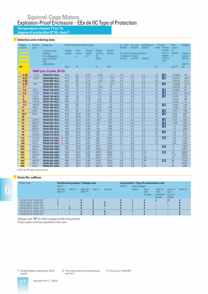
6/4 Siemens M 11 · 2000
6
Ratedoutput
Framesize
Order No. Performance at rated output Lo.-rotor Lo.rotor Breakdown Torque Mo-mentofinertiaJ
Weight
For Order No.suffixesfor voltage andtype of constr.seetable below
torque current torque class charac-teristicacc. topages2/10 to2/13
Ratedspeed
Effi-ciencyh
Powerfactorp.f.
Ratedcurrentat400 V
Ratedtorque For direct-online starting in
multiples of ratedType ofconstr.IM B 3
approx.
torque current torque
HP rpm % A Nm CL kg m2 kg
1000 rpm, 6-pole, 50 Hz0.25 71 M 1MJ6 073–6CA . . 870 63 0.70 0.82 2.7 2.2 3.1 2.2 16 6 0.0009 160.370.55
80 M 1MJ6 080–6CA . .1MJ6 083–6CA . .
910900
6464
0.710.74
1.181.67
3.95.8
1.92.0
3.33.5
2.02.1
1616
6 0.00150.0018
34.622.5
0.751.1
90 L 1MJ6 096–6CA . .1MJ6 097–6CA . .
910905
6972
0.760.75
2.12.95
8.012
2.22.4
3.94.3
2.32.4
1616
6 0.00280.0035
31.832
1.5 100 L 1MJ6 106–6CA . . 930 72 0.75 4.0 15 2.0 4.5 2.1 16 6 0.0063 392.2 112 M 1MJ6 113–6CA . . 945 76 0.76 5.5 22 2.2 4.8 2.5 16 6 0.011 52.5345.5
132 S132 M132 M
1MJ6 130–6CA . .1MJ6 133–6CA . .1MJ6 134–6CA . .
945945950
787983
0.750.760.76
7.49.6
12.6
304055
2.02.02.2
4.85.05.4
2.22.42.5
161616
6 0.0150.0190.025
7886
1107.5
11160 M160 L
1MJ6 163–6CA . .1MJ6 166–6CA . .
960960
8687
0.720.74
17.524.5
75109
2.12.3
5.15.5
2.52.5
1616
6 0.0410.049
134167
15 180 L 1MJ6 186–6CA . . 970 89 0.83 29.5 148 2.6 6.3 2.4 16 4 0.20 18018.522
200 L 1MJ6 206–6CA . .1MJ6 207–6CA . .
975975
90.290.8
0.820.83
3642.5
181215
2.62.5
6.35.7
2.32.3
1616
4 0.290.33
240255
30 225 M 1MJ6 223–6CA . . 978 92.0 0.84 561) 293 2.6 5.7 2.2 16 4 0.57 33037 250 M 1MJ6 253–6CA . . 980 92.4 0.84 69 361 2.6 6.0 2.1 16 4 0.89 4404555
280 S280 M
1MJ6 280–6CA . .1MJ6 283–6CA . .
982984
93.093.6
0.860.86
8199
438534
2.42.5
6.06.2
2.32.4
1616
4 1.31.5
560600
7590
315 S315 M
1MJ6 310–6CA . .1MJ6 313–6CA . .
988988
93.894.2
0.850.85
136162
725870
2.42.4
6.26.2
2.52.5
1616
4 2.42.9
810870
110132160
315 M315 M315 L
1MJ8 313–6AC . .1MJ8 314–6AC . .1MJ8 316–6AC . .
990990990
95.395.495.5
0.860.870.87
195228275
106112731543
2.12.12.1
6.86.66.6
2.32.32.3
131313
17 4.84.86.0
115011501250
200250
355 M355 L
1MJ8 353–6AD . .1MJ8 356–6AD . .
990990
95.695.8
0.860.85
3504402)
19292412
1.11.1
6.56.5
2.22.2
77
17 89
19002200
280315355
400 S400 M400 L
1MJ8 400–6AD . .1MJ8 403–6AD . .1MJ8 406–6AD . .
994994994
96.296.396.4
0.850.850.85
4952)5602)6252)
269030263411
1.01.01.0
5.86.05.8
2.352.42.35
777
15 1617.519
280030003200
400450500
450 M450 L450 L
1MJ8 453–6AD . .1MJ8 456–6AD . .1MJ8 457–6AD . .
995995995
96.596.696.7
0.850.850.85
7052)7902)8801)2)
383943194799
0.90.90.9
5.85.85.9
2.452.42.45
777
15 283134
370040004300
V EEx de IIB type of protection.
1) Parallel feeders required for 400 Vsupply.
2) The motors have 2 terminal boxes,see Part 7.
3) Only up to 1MJ6 083.
Motor type Penultimate position: Voltage code Last position: Type of construction code50 Hz IM B 3 (extra charge)230 Vd/ 400 V* 400 Vd/ 500 V* 500 Vd IM B 5 IM V 1 IM B 14 IM B 14 IM B 35400 V* 690 V* with
canopywithstandardflange
withcustomflange
1MJ6 073 to 1MJ6 0971MJ6 106 to 1MJ6 1661MJ6 186 to 1MJ6 2071MJ6 223 to 1MJ6 313
111–
–––4
6666
3333
–55–
0000
1111
4444
2–––
33)–––
6666
1MJ8 313 to 1MJ8 3161MJ8 353 to 1MJ8 457
––
––
66
33
55
00
1–
44
––
––
66
Voltage code “9” for other voltages and/or frequencies.Order codes must be specified in this case.
Temperature classes T1 to T4,degree of protection IP 55,class F
Squirrel-Cage MotorsExplosion-Proof Enclosure×EEx de IIC Type of Protection
Selection and ordering data
Order No.suffixes

6/5Siemens M 11 · 2000
6
Ratedoutput
Framesize
Order No. Performance at rated output Lo.-rotor Lo.rotor Breakdown Torque Mo-mentofinertiaJ
Weight
For Order No.suffixesfor voltage andtype of constr.seetable below
torque current torque class charac-teristicacc. topages2/10 to2/13
Ratedspeed
Effi-ciencyh
Powerfactorp.f.
Ratedcurrentat400 V
Ratedtorque For direct-online starting in
multiples of ratedType ofconstr.IM B 3
approx.
torque current torque
HP rpm % A Nm CL kg m2 kg
750 rpm, 8-pole, 50 Hz0.370.55
90 L 1MJ6 096–8CB . .1MJ6 097–8CB . .
655655
6165
0.760.76
1.161.62
5.37.9
1.41.5
2.82.9
1.71.7
1313
13 0.00250.0035
27.529.5
0.751.1
100 L 1MJ6 106–8CB . .1MJ6 107–8CB . .
665685
6574
0.770.74
2.152.9
1116
1.61.8
3.53.9
1.82.0
1313
13 0.00530.0070
34.548
1.5 112 M 1MJ6 113–8CB . . 700 74 0.73 4.0 21 1.8 4.4 2.0 13 13 0.013 522.23
132 S132 M
1MJ6 130–8CB . .1MJ6 133–8CB . .
695700
7476
0.720.72
6.07.9
3040
1.71.9
4.24.4
2.12.2
1313
13 0.0140.019
7886
45.57.5
160 M160 M160 L
1MJ6 163–8CB . .1MJ6 164–8CB . .1MJ6 166–8CB . .
715710715
818384
0.720.720.72
9.913.317.9
5474
100
2.12.32.6
4.85.15.8
2.32.52.8
131313
1366
0.0350.0430.062
121134159
11 180 L 1MJ6 186–8CB . . 725 87 0.70 26 145 2.0 5.0 2.2 13 14 0.21 18515 200 L 1MJ6 207–8CB . . 725 87.5 0.78 32 198 2.1 5.0 2.2 13 14 0.37 26518.522
225 S225 M
1MJ6 220–8CB . .1MJ6 223–8CB . .
725725
88.690.1
0.800.81
37.543.5
244290
2.12.1
5.05.0
2.22.2
1313
14 0.580.66
325350
30 250 M 1MJ6 253–8CB . . 730 91.6 0.81 58 392 2.1 5.0 2.1 13 14 1.1 4653745
280 S280 M
1MJ6 280–8CB . .1MJ6 283–8CB . .
732734
92.792.8
0.820.83
7084
483585
2.22.2
5.55.5
2.22.2
1313
14 1.41.6
570620
5575
315 S315 M
1MJ6 310–8CB . .1MJ6 313–8CB . .
738738
93.193.6
0.820.82
104140
712970
2.22.3
6.06.2
2.42.5
1313
14 2.33.0
780890
90110132
315 M315 M315 L
1MJ8 313–8AB . .1MJ8 314–8AB . .1MJ8 316–8AB . .
740740740
94.494.494.4
0.790.790.80
175210255
116114201704
1.71.71.8
6.16.16.1
2.02.02.0
101010
17 4.84.86.0
115011501250
160200
355 M355 L
1MJ8 353–8AD . .1MJ8 356–8AD . .
740740
95.195.4
0.830.83
292365
20652581
1.31.3
5.35.3
2.22.2
77
17 1214.7
19002250
250280315
400 S400 M400 L
1MJ8 400–8AD . .1MJ8 403–8AD . .1MJ8 406–8AD . .
743743743
95.895.996.0
0.840.840.84
4501)5001)5651)
321335994049
1.11.11.1
5.55.45.5
2.42.32.35
777
15 1617.519
280030003200
355400450
450 M450 L450 L
1MJ8 453–8AD . .1MJ8 456–8AD . .1MJ8 457–8AD . .
745745745
96.296.396.4
0.840.840.84
6351)7151)8001)
455151285768
1.01.01.0
5.65.65.5
2.352.42.35
777
15 273033
370040004300
V EEx de IIB type of protection.
Motor type Penultimate position: Voltage code Last position: Type of construction code50 Hz IM B 3 (extra charge)230 Vd/ 400 V* 400 Vd/ 500 V* 500 Vd IM B 5 IM V 1 IM B 14 IM B 14 IM B 35400 V* 690 V* with
canopywithstandardflange
withcustomflange
1MJ6 096 and 1MJ6 0971MJ6 106 to 1MJ6 1661MJ6 186 to 1MJ6 2071MJ6 220 to 1MJ6 313
111–
–––4
6666
3333
–55–
0000
1111
4444
2–––
32)–––
6666
1MJ8 313 to 1MJ8 3161MJ8 353 to 1MJ8 457
––
––
66
33
55
00
1–
44
––
––
66
Voltage code “9” for other voltages and/or frequencies.Order codes must be specified in this case.
Temperature classes T1 to T4,degree of protection IP 55,class F
Squirrel-Cage MotorsExplosion-Proof Enclosure×EEx de IIC Type of Protection
Selection and ordering data
Order No.suffixes
1) The motors have 2 terminal boxes,see Part 7.
2) Only up to 1MJ6 083.
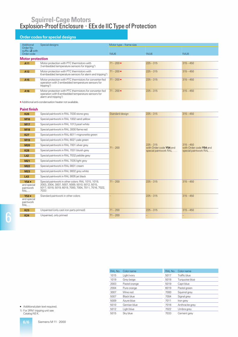
6/6 Siemens M 11 · 2000
6
Order codes for special designs
AdditionalOrder No.suffix –Z withOrder code
Special designs Motor type – frame size
1MJ6 1MJ6 1MJ8
Motor protectionA11 Motor protection with PTC thermistors with
3 embedded temperature sensors for tripping1)71 – 200 V 225 – 315 315 – 450
A12 Motor protection with PTC thermistors with6 embedded temperature sensors for alarm and tripping1)
71 – 200 V 225 – 315 315 – 450
A15 Motor protection with PTC thermistors for converter-fedoperation with 3 embedded temperature sensors fortripping1)
71 – 200 V 225 – 315 315 – 450
A16 Motor protection with PTC thermistors for converter-fedoperation with 6 embedded temperature sensors foralarm and tripping1)
71 – 200 V 225 – 315 315 – 450
V Additional anti-condensation heater not available.
Paint finishK26 Special paintwork in RAL 7030 stone grey Standard design 225 – 315 315 – 450
M16 Special paintwork in RAL 1002 sand yellow
71 – 200225 – 315with Order code Y54 andspecial paintwork RAL . . . .
315 – 450with Order code Y54 andspecial paintwork RAL . . . .
M17 Special paintwork in RAL 1013 pearl white
M18 Special paintwork in RAL 3000 flame red
K27 Special paintwork in RAL 6011 mignonette green
M19 Special paintwork in RAL 6021 pale green
M20 Special paintwork in RAL 7001 silver grey
K28 Special paintwork in RAL 7031 bluish grey
L42 Special paintwork in RAL 7032 pebble grey
M21 Special paintwork in RAL 7035 light grey
M22 Special paintwork in RAL 9001 cream
M23 Special paintwork in RAL 9002 grey white
L43 Special paintwork in RAL 9005 jet black
Y54 Á
and specialpaintworkRAL....
Special paintwork in other colors: RAL 1015, 1019,2003, 2004, 3007, 5007, 5009, 5010, 5012, 5015,5017, 5018, 5019, 6019, 7000, 7004, 7011, 7016, 7022,7033
71 – 200 225 – 315 315 – 450
Y53 Á
and specialpaintworkRAL....
Standard paintwork in other colors – 225 – 315 315 – 450
K23 Unpainted (only cast iron parts primed) 71 – 200 225 – 315 315 – 450
K24 Unpainted, only primed 71 – 200 – –
Á Additional plain text required.1) For 3RN1 tripping unit see
Catalog NS K.
RAL No. Color name RAL No. Color name
1015 Light ivory 5017 Traffic blue
1019 Grey beige 5018 Turquoise blue
2003 Pastel orange 5019 Capri blue
2004 Pure orange 6019 Pastel green
3007 Wine red 7000 Squirrel grey
5007 Black blue 7004 Signal grey
5009 Azure blue 7011 Iron grey
5010 Gentian blue 7016 Anthracite grey
5012 Light blue 7022 Umbra grey
5015 Sky blue 7033 Cement grey
Squirrel-Cage MotorsExplosion-Proof Enclosure×EEx de IIC Type of Protection

6/7Siemens M 11 · 2000
6
Order codes for special designs
AdditionalOrder No.suffix –Z withOrder code
Special designs Motor type – frame size
1MJ6 1MJ6 1MJ8
Mechanical featuresK09 Side-mounted terminal box, right
(when viewed in the drive end side)90 – 200 225 – 315 315 – 450
K10 Side-mounted terminal box, leftwhen viewed in the drive end side)
90 – 200 225 – 315 315 – 450
K83 Terminal box rotated 90°, entry from drive-end on AS 71 – 200 225 – 315 315 – 450
K84 Terminal box rotated 90°, entry from non-drive end on BS 71 – 200 225 – 315 315 – 450
K85 Terminal box rotated 180° 71 – 200 225 – 315 315 – 450
K01 Vibration severity grade R 71 – 200 225 – 315 315 – 450
K16 Second started shaft-end1) 71 – 200 225 – 315 315 – 450
K17 Drive-end seal for flange-mounting motors2) 71 – 200 225 – 315 315 – 450
K20 Bearings for increased cantilever forces 180 – 200not available withvibration severity grade R
225 – 250 –
K40 Regreasing device 180 – 200 225 – 250, standard design from
K30 VIK design3) 71 – 200 225 – 315 315 – 355
K31 Extra rating plate, loose 71 – 200 225 – 315 315 – 450
Y82 Á
forpurchasers’data
Extra rating plate 71 – 200 225 – 315 315 – 450
K37 Low-noise design for 2-pole motors with clockwisedirection of rotation4)
132 – 200 225 – 315 315 – 400
K38 Low-noise design for 2-pole motors with anticlockwisedirection of rotation4)
132 – 200 225 – 315 315 – 400
K45 Anti-condensation heater for 230 V 71 – 200Additional PTC thermistornot available
225 – 315 315 – 400
K46 Anti-condensation heater for 115 V 71 – 200Additional PTC thermistornot available
225 – 315 315 – 400
CertificationB02 Factory test in accordance with EN 10 204 2.3 71 – 200 – –
Á Additional plain text required.1) Vertically mounted motors from
frame size BG 180 M with 1MJ6on request, low-noise design notavailable.
2) Not available for IM V 3 type ofconstruction, only 4- to 8-polemotors from frame size 180 M.
3) Additional low-noise design isrequired for frame size 315 S orlarger.
4) The motors are up to 80 mm longerthan the standard design. A secondshaft extension cannot bemounted.
Squirrel-Cage MotorsExplosion-Proof Enclosure×EEx de IIC Type of Protection
6/8 Siemens M 11 · 2000
6
Notes
Squirrel-Cage Motors
7/1Siemens M 11 · 2000
7
Монтажное исполнение IM B 37/2 1LA5, 1LA7 è 1MA7
7/4 1LA9
7/6 1LG8
7/8 1LA6 è 1MA6
7/10 1LA8 è 1MA8
7/12 1UA7
7/14 1MJ6
7/16 1MJ6 è 1MJ8
Монтажное исполнение IM B 5 и IM V 17/18 1LA5, 1LA7 è 1MA7
7/20 1LA9
7/22 1LG8
7/24 1LA6 è 1MA6
7/26 1LA8 è 1MA8
7/28 1UA7
7/30 1MJ6
7/32 1MJ6 è 1MJ8
Монтажное исполнение IM B 357/34 1LA5, 1LA7 è 1MA7
7/36 1LA9
7/38 1LG8
7/40 1LA6 è 1MA6
7/42 1LA8 è 1MA8
7/44 1UA7
7/46 1MJ6
7/48 1MJ6
Монтажное исполнение IM B 147/50 1LA7 è 1MA7
7/52 1LA9
7/54 1LG8
7/56 1MJ6
Ìîäóëüíàÿ òåõíîëîãèÿ
7/58 1LA5 è 1LA7
Êîðîòêîçàìêêóòûå ýëåêòðîäâèãàòåëèSIEMENS ÐàçìåðûÏðèìå÷àíèå
■ Размеры на чертежах в соответствии с DIN EN 50 347 иIEC 60 072.
■ Âàë (DIN 748) è öåíòðèðóþùèå âûñòóïû (DIN 42 948)
óêàçàííûå â òàáëèöàõ, óäîâëåòâîðÿþò ñëåäóþùåìó:
Ðàçìåðû ISO â ñîîñòâ ñ
ñèìâîë DIN ISO 286-2
D, DA < 30 j6
> 30 to 50 k6
> 50 m6
N < 250 j6
> 250 h6
F, FA h9
■ Допуски на размер:Îòêëîíåíèÿ, óêàçàííûå íèæå äîïóñêàþòñÿ äëÿ
ðàçìåðîâ, âûäåëåííûõ â òàáëèöàõ:
Ðàçìåðû Ðàçìåðû Допустимоеñèìâîë отклонение
A, B < 250 ± 0.75
> 250 to 500 ± 1.0
> 500 to 750 ± 1.5
> 750 to 1000 ± 2.0
> 1000 ± 2.5
M < 200 ± 0.25
> 200 to 500 ± 0.5
> 500 ± 1.0
H < 250 – 0.5
> 250 – 1.0
E, EA – 0.5
Øïîíî÷íûå ïàçû (ðàçìåðû GA, GC, F è FA
ñîîòâåòñòâóþò DIN 6885 ×àñòü 1).
# Фланцы
В DIN EN 50 347, плоские фланцы FF с отверстиями длясквозного болта и выступами FT с отверстиями под винтсоответствуют определенному типоразмеру. Фланцы A и C в соответствие с DIN 42 948. См. таблицу справа.
■ Все заявленные размеры в мм.
Çàìå÷àíèå
Сименс сохраняет за собой право изменять техническуюинформацию без уведомления. Размеры в каталоге могутотличаться от действительных. Уточнение при заказе.
Соответствие фланцев типоразмеру электродвигателяÔëàíöû ïîä ñêâîçíîé áîëò ïîä âèíò
Типоразмердвигателя DIN EN 50 347 DIN 42 948 DIN EN 50 347 DIN 42 948
5663718090
100112132160180200225250280315
FF 100FF 115FF 130FF 165FF 165FF 215FF 215FF 265FF 300FF 300FF 350FF 400FF 500FF 500FF 600
A 120A 140A 160A 200A 200A 250A 250A 300A 350A 350A 400A 450A 550A 550A 660
FT 65FT 75FT 85FT 100FT 115FT 130FT 130FT 165FT 215
C 80C 90C 105C 120C 140C 160C 160C 200C 250

7/10 Siemens M 11 · 2000
7
Короткозамкнутые электродвигателиРазмеры
1LA8 · Типоразмер от 315 до 4501MA8 · Типоразмер от 315 до 355
Монтажное исполнение IM B 3
Для двигателя Символы размеров
Высотавала
Тип1LA8 . . .1MA8 . . .
К-вопол.
по IECпо DIN
Ab
AAn
ABf
AC1)g
ADp1
AGr
Ba
BAm
BBe
BCx3
BEx
Cw1
CAw2
Hh
HAc
HBv
315 . . . . 315. . . . 317
24 to 8
560 120 680 710 680 560 630 180 780 195 135 180180
435 315 28 330
. . . . 31 . 4 to 82) 200355 . . . . 353
. . . . 355
. . . . 357
24 to 8
630 150 780 790 710
(840)
585
(740)
800 220 980 185 135
(100)
200200
470 355 35 400
(360). . . . 35 . 4 to 82) 224
400 1LA8 4031LA8 4051LA8 407
24 to 8
710 150 860 880 875 775 900 220 1080 186 100 224 506 400 35 440
450 1LA8 4531LA8 4551LA8 457
23)4 to 8
800 180 980 970 910 810 1000 260 1220 170 100 250 540 450 42 525
1) Измеренный поперек головок болтов(не на скосах кожуха вентилятора).
2) С подшипником для нагруженнойконсоли (привод через шкив и т.д.).
3) Только для 50 Гц.
■ Размеры в скобках относятся к 1LA8 357 с 2-мя и 4-мя полюсами.
HK
AD
BB
D
B
F
GA
C
BE
LCL
M1-
5084
c
AC
EBA
DB
KCA EA
DA
DC
FA
GC
HAH
K´A
AA
AB
AG HB
HD
BC
LL
EB EC

7/11Siemens M 11 · 2000
7
Короткозамкнутые электродвигателиРазмеры
Монтажное исполнение IM B 3
Длина вала со стороны привода Длина вала с полевого концаHDp
HKx4
Ks
K’s1
Lk
LCk1
LLx1
Os3
Dd
DBd6
EI
EB Fu
GAt
DAd1
DCd7
EAl1
EC FAu1
GCt1
835 229 26 33 13701400
14951555
330 M 72 x 2 6585
M 20M 20
140170
125140
1822
6990
5070
M 16M 20
110140
100125
1420
53.574.5
1420 1575 95 M 24 170 140 25 100 70 M 20 140 125 20 74.5905
(945)
229
(320)
33 40 15951625
17501810
330
(550)
M 72 x 2
(ф 80)
7595
M 20M 24
140170
125140
2025
79.5100
6080
M 20 140170
125140
1822
6485
1690 1874 100 M 24 210 180 28 106 80 M 20 170 140 22 851025 320 33 40 1785
182519402010
550 ф 80 80110
M 20M 24
170210
140180
2228
85116
7090
M 20M 24
140170
125140
2025
74.595
1110 320 39 47 19451985
21002210
550 ф 80 90120
M 24 170210
140180
2532
95127
75100
M 20M 24
140210
125180
2028
79.5106

7/16 Siemens M 11 · 2000
7
Короткозамкнутые электродвигателиРазмеры
AG
HK
M1-
5139
aLCL, L´
O
D
DBE
LL
BE
AC
DA
EA
GC
FA
HB H
D
AQ
B
BABB
B´BA´
C
BC
K
CA'CA
DC
ASAD
K´ AG´A
AAAB
HA
HB
'
AA
H
LM,LM´
F
GA
EB EC
Типоразмеры 180 M/L, 225 S/M, 280 S/M280 S/M и 315 S/M имеют по два отверстия в каждой лапе с полевой стороны.
1MJ6 · Типоразмер от 180 M до 315 M1MJ8 · Типоразмер от 315 M до 450 L
Монтажное исполнение IM B 3
Для двигателя Символы размеров
Высота Тип по IECвала по DIN
Ab
AAn
ABf
AC1)g
ADp1
AD’r3
AGr
AG’y
AQj
ASr2
Ba
B’a’
BAm
BA’m1
BBe
BCx3
BEx
Cw1
CAw2
CA’w’2
Hh
180 M 1MJ6 183 2 and 4 279 65 344 375 310 – 138 270 340 82 241* 279 70 108 319 35 75 121 259 – 180180 L 1MJ6 186 4 to 8 279 65 344 375 310 – 138 270 340 82 241 279* 70 108 319 35 75 121 – 221 180200 L 1MJ6 206 2
6318 80 398 415 360 – 164 295 340 98.5305 – 85 85 355 42 85 133 239 – 200
1MJ6 207 24 to 8
318 80 398 415 360 – 164 295 340 98.5305 – 85 85 355 42 85 133 239 – 200
225 S 1MJ6 220 4 and 8 356 80 436 470 375 – 155 320 425 100 286* 311 85 110 361 25 90 149 269 – 225225 M 1MJ6 223 2
4 to 8356 80 436 470 375 – 155 320 425 100 286 311* 85 110 361 25 90 149 – 244 225
250 M 1MJ6 253 24 to 8
406 100 506 520 465 – 200 385 470 120 349 – 100 100 409 39 105 168 283 – 250
280 S 1MJ6 280 24 to 8
457 100 557 575 490 – 200 410 525 120 368* 419 100 151 479 30 105 190 317 – 280
280 M 1MJ6 283 24 to 8
457 100 557 575 490 – 200 410 525 120 368 419* 100 151 479 30 105 190 – 266 280
315 S 1MJ6 310 24 to 8
508 120 628 645 555 – 250 475 590 135 406* 457 125 171 527 32 90 216 358 – 315
315 M 1MJ6 313 24 to 8
508 120 628 645 555 – 250 475 590 135 406 457* 125 171 527 32 90 216 – 307 315
315 M 1MJ8 313 24 to 8
508 120 630 622 – – 494 – – – 457 – 130 130 570 – – 216 – – 315
1MJ8 314 4 and 6 508 120 630 622 – – 494 – – – 457 – 130 130 570 – – 216 – – 315315 L 1MJ8 316 2 508 120 630 622 – – 494 – – – 508 – 130 130 621 – – 216 – – 315
4 to 8355 M 1MJ8 353 2
4 to 8610 120 700 698 – 740 480 – – – 560 – 150 150 650 – – 254 – – 355
1MJ8 354 4 610 120 700 698 – 740 480 – – – 560 – 150 150 650 – – 254 – – 355355 L 1MJ8 356 2
4 to 8610 120 700 698 – 740 480 – – – 630 – 150 150 720 – – 254 – – 355
1MJ8 357 4 610 120 700 698 – 740 480 – – – 630 – 150 150 720 – – 254 – – 355400 S 1MJ8 400 2
4 to 8686 120 780 792 – 750 480 – – – 560 – 200 200 650 – – 280 – – 400
400 M 1MJ8 403 24 to 8
686 120 780 792 – 750 480 – – – 630 – 200 200 720 – – 280 – – 400
400 L 1MJ8 406 24 to 8
686 120 780 792 – 750 480 – – – 710 – 200 200 800 – – 280 – – 400
450 M 1MJ8 453 24 to 8
750 150 900 900 – 810 480 – – – 710 – 200 200 870 – – 280 – – 450
450 L 1MJ8 456 24 to 8
750 150 900 900 – 810 480 – – – 800 – 200 200 960 – – 280 – – 450
450 L 1MJ8 457 24 to 8
750 150 900 900 – 810 480 – – – 900 – 200 200 1060 – – 280 – – 450
* Это размер предписан указанному типоразмеру стандартом DIN EN 50 347.
1) Измеренный поперек головок болтов.
2) Конструкция с малошумным вентилятором.
3) Второй конец вала невозможен в малошумной конструкции.

7/17Siemens M 11 · 2000
7
Короткозамкнутые электродвигателиРазмеры
Конструкция для 1MJ8 с номинальнымтоком > 400A (две клемных коробки).
Монтажное исполнение IM B 3
M1-5
16
2a
AD'AD'
HD
'
Длина вала со стороны привода Длина вала с полевого конца 3)HAc
HBv
HB’v’
HDp
HD’p2
HKx4
Ks
K’s1
Lk
L’2)k’
LC3)k1
LLx1
LMk2
LM’2)k2’
Os3
Dd
DBd6
EI
EB Fu
GAt
DAd1
DCd7
EAl1
EC FAu1
GCt1
26 450 42 490 – 123 15 20 716 770 841 164 800 885 M 40 x 1.5 48 M 16 110 100 14 51.5 48 M 16 110 100 14 51.526 450 42 490 – 123 15 20 716 – 841 164 800 – M 40 x 1.5 48 M 16 110 100 14 51.5 48 M 16 110 100 14 51.534 500 36 560 – 148 19 25 772 825
–897 197 856 910
–M 50 x 1.5 55 M 20 110 100 16 59 48
55M 16M 20
110 100 1416
51.559
34 500 36 560 – 148 19 25 772 825–
897 197 856 910–
M 50 x 1.5 55 M 20 110 100 16 59 4855
M 16M 20
110 100 1416
51.559
34 540 70 600 – 148 19 25 835 – 954 197 935 – M 50 x 1.5 60 M 20 140 125 18 64 55 M 20 110 100 16 5934 540 70 600 – 148 19 25 805
835855
–924954
197 905935
955–
M 50 x 1.5 5560
M 20 110140
100125
1618
5964
4855
M 16M 20
110 100 1416
51.559
42 620 50 715 – 193 24 30 930 1010–
10501080
234 1030 1110–
M 63 x 1.5 6065
M 20 140 125 18 6469
5560
M 20 110140
100125
1618
5964
42 675 80 770 – 193 24 30 1005 1080–
1155 234 1115 1230–
M 63 x 1.5 6575
M 20 140 125 1820
6979.5
6065
M 20 140 125 18 6469
42 675 80 770 – 193 24 30 1005 1080–
1155 234 1115 1230–
M 63 x 1.5 6575
M 20 140 125 1820
6979.5
6065
M 20 140 125 18 6469
56 750 65 870 – 225 28 35 11101140
1185–
12601290
266 12201250
1295–
M 63 x 1.5 6580
M 20 140170
125140
1822
6985
6070
M 20 140 125 1820
6474.5
56 750 65 870 – 225 28 35 11101140
1185–
12601290
266 12201250
1295–
M 63 x 1.5 6580
M 20 140170
125140
1822
6985
6070
M 20 140 125 1820
6474.5
30 – – 922 – – 28 28 12411343
– 14401563
– 14041455
– M 63 x 1.5 6580
M 20M 20
140170
125140
1822
6985
6580
M 20M 20
140170
125140
1822
6985
30 – – 922 – – 28 28 1343 – 1563 – 1455 – M 63 x 1.5 80 M 20 170 140 22 85 80 M 20 170 140 22 8530 – – 974 – – 28 28 1351 – 1550 – 1514 – 35 – 75 65 M 20 140 125 18 69 65 M 20 140 125 18 69
1453 1673 1565 80 M 20 170 140 22 85 80 M 20 170 140 22 8530 – – 1063 875 – 28 28 1650
1680– 1850
1910– – – 35 – 75 75
90M 20M 24
140170
125140
2025
79.595
7590
M 20M 24
140170
125140
2025
79.595
30 – – 1063 875 – 28 28 1680 – 1910 – – – 35 – 75 90 M 24 170 140 25 95 90 M 24 170 140 25 9530 – – 1063 875 – 28 28 1780
1810– 1980
2040– – – 35 – 75 75
90M 20M 24
140170
125140
2025
79.595
7590
M 20M 24
140170
125140
2025
79.595
30 – – 1063 875 – 28 28 1810 – 2040 – – – 35 – 75 90 M 24 170 140 25 95 90 M 24 170 140 25 9537 – – 1141 860 – 35 35 1650
1720– – – – – 35 – 75 75
100M 20M 24
140210
125180
2028
79.5106
75100
M 20M 24
140210
125180
2028
79.5106
37 – – 1141 860 – 35 35 17701840
– – – – – 35 – 75 75100
M 20M 24
140210
125180
2028
79.5106
75100
M 20M 24
140210
125180
2028
79.5106
37 – – 1141 860 – 35 35 19001970
– – – – – 35 – 75 75100
M 20M 24
140210
125180
2028
79.5106
75100
M 20M 24
140210
125180
2028
79.5106
37 – – 1239 1150 – 35 35 17901830
– – – – – 35 – 75 80100
M 20M 24
170210
140180
2228
85106
80100
M 20M 24
170210
140180
2228
85106
37 – – 1239 1150 – 35 35 18901930
– – – – – 35 – 75 80100
M 20M 24
170210
140180
2228
85106
80100
M 20M 24
170210
140180
2228
85106
37 – – 1239 1150 – 35 35 19902030
– – – – – 35 – 75 80100
M 20M 24
170210
140180
2228
85106
80100
M 20M 24
170210
140180
2228
85106
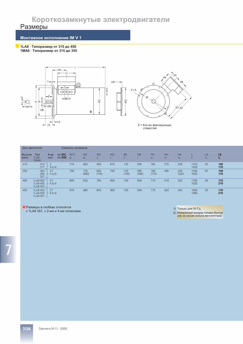
7/26 Siemens M 11 · 2000
7
Короткозамкнутые электродвигателиРазмеры
N DP
F
GA
T
LALE
O
BE
LLHH
LM
L
AQ
M1-5
08
3c
AC
HKHC
HB
ME
DBADAG´EB
Z x S
Z = Кол-во фиксирующих отверстий
1LA8 · Типоразмер от 315 до 4501MA8 · Типоразмер от 315 до 355
Монтажное исполнение IM V 1
Для двигателя Символы размеров
Высотавала
Тип1LA8 . . .1MA8 . . .
К-вопол.
по IECпо DIN
AC2)g
ADp1
AG’y
AQj
BEx
HBr
HCr2
HHo1
HKx4
Lk
LAc1
LEi2
315 . . . . 315. . . . 317
24 to 8
710 690 560 670 135 285 165 375 229 13701400
25 140170
355 . . . . 353. . . . 355. . . . 357
21)4 to 8
790 730(880)
600(745)
750 135(100)
285(400)
165(175)
385 229(320)
15951625
25 140170
400 1LA8 4031LA8 4051LA8 407
21)4 to 8
880 930 795 850 100 400 175 410 320 17851825
28 170210
450 1LA8 4531LA8 4551LA8 457
21)4 to 8
970 980 845 950 100 400 175 420 320 19451985
30 170210
1) Только для 50 Гц.
2) Измеренный поперек головок болтов(не на скосах кожуха вентилятора)
■ Размеры в скобках относятся к 1LA8 357, с 2-мя и 4-мя полюсами.

7/27Siemens M 11 · 2000
7
Короткозамкнутые электродвигателиРазмеры
Монтажное исполнение IM V1
Длина вала со стороны приводаLLx1
LMk2
Me1
Nb1
Os3
Pa1
Ss2
Tf1
Zz1
Dd
DBd6
EI
EB Fu
GAt
330 15001530
740 680 M 72 x 2 800 22 6 8 6585
M 20 140170
125140
1822
6990
330(550)
17351765
840 780 M 72 x 2(ф 80)
900 22 6 8 7595
M 20M 24
140170
125140
2025
79.5100
550 19351975
940 880 ф 80 1000 22 6 8 80110
M 20M 24
170210
140180
2228
85116
550 21052145
1080 1000 ф 80 1150 26 6 8 90120
M 24 170210
140180
2532
95127
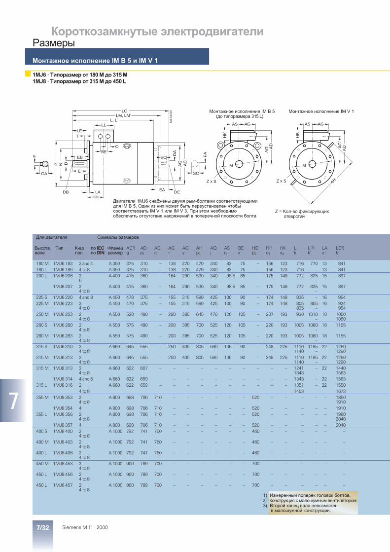
7/32 Siemens M 11 · 2000
7
Короткозамкнутые электродвигателиРазмеры
AG
M
HK
M1-
5141
b
LM, LM´L, L´
LET
O
F
GA
P N D
DB
E
LA
LL
BE
AQ
DA
EA
GC
FA A
G´
AD
DC
AS
HH
LC
AC
AG
M
HK
Z x S
AG
´
AH
AS
AD
Z x S
EB EC
1MJ6 · Типоразмер от 180 M до 315 M1MJ8 · Типоразмер от 315 M до 450 L
Монтажное исполнение IM B 5 и IM V 1
Z = Кол-во фиксирующих отверстий
Двигатели 1MJ6 снабжены двумя рым-болтами соответствующимидля IM B 5. Один из них может быть переустановлен чтобысоответствовать IM V 1 или IM V 3. При этом необходимо обеспечить отсутствие напряжений в поперечной плоскости болта
Монтажное исполнение IM B 5(до типоразмера 315 L)
Монтажное исполнение IM V 1
Для двигателя Символы размеров
Высотавала
Тип К-вопол.
по IECпо DIN
Фланецразмер
AC1)g
ADp1
AD’r3
AGr
AG’y
AHp3
AQj
ASr2
BEx
HD’p2
HHo1
HKx4
Lk
L’2)k’
LAc1
LC3)k1
180 M 1MJ6 183 2 and 4 A 350 375 310 – 138 270 470 340 82 75 – 156 123 716 770 13 841180 L 1MJ6 186 4 to 8 A 350 375 310 – 138 270 470 340 82 75 – 156 123 716 – 13 841200 L 1MJ6 206 2
6A 400 415 360 – 164 290 530 340 98.5 85 – 175 148 772 825
–15 897
1MJ6 207 24 to 8
A 400 415 360 – 164 290 530 340 98.5 85 – 175 148 772 825–
15 897
225 S 1MJ6 220 4 and 8 A 450 470 375 – 155 315 580 425 100 90 – 174 148 835 – 16 954225 M 1MJ6 223 2
4 to 8A 450 470 375 – 155 315 580 425 100 90 – 174 148 805
835855
–16 924
954250 M 1MJ6 253 2
4 to 8A 550 520 480 – 200 385 645 470 120 105 – 207 193 930 1010
–18 1050
1080280 S 1MJ6 280 2
4 to 8A 550 575 490 – 200 395 700 525 120 105 – 220 193 1005 1080
–18 1155
280 M 1MJ6 283 24 to 8
A 550 575 490 – 200 395 700 525 120 105 – 220 193 1005 1080–
18 1155
315 S 1MJ6 310 24 to 8
A 660 645 555 – 250 435 805 590 135 90 – 248 225 11101140
1185–
22 12601290
315 M 1MJ6 313 24 to 8
A 660 645 555 – 250 435 805 590 135 90 – 248 225 11101140
1185–
22 12601290
315 M 1MJ8 313 24 to 8
A 660 622 607 – – – – – – – – – – 12411343
– 22 14401563
1MJ8 314 4 and 6 A 660 622 659 – – – – – – – – – 1343 – 22 1563315 L 1MJ8 316 2 A 660 622 659 – – – – – – – – – – 1351 – 22 1550
4 to 8 1453 1673355 M 1MJ8 353 2
4 to 8A 800 698 706 710 – – – – – – 520 – – – – – 1850
19101MJ8 354 4 A 800 698 706 710 – – – – – – 520 – – – – – 1910
355 L 1MJ8 356 24 to 8
A 800 698 706 710 – – – – – – 520 – – – – – 19802040
1MJ8 357 4 A 800 698 706 710 – – – – – – 520 – – – – – 2040400 S 1MJ8 400 2
4 to 8A 1000 792 741 760 – – – – – – 460 – – – – – –
400 M 1MJ8 403 24 to 8
A 1000 792 741 760 – – – – – – 460 – – – – – –
400 L 1MJ8 406 24 to 8
A 1000 792 741 760 – – – – – – 460 – – – – – –
450 M 1MJ8 453 24 to 8
A 1000 900 789 700 – – – – – – 700 – – – – – –
450 L 1MJ8 456 24 to 8
A 1000 900 789 700 – – – – – – 700 – – – – – –
450 L 1MJ8 457 24 to 8
A 1000 900 789 700 – – – – – – 700 – – – – – –
1) Измеренный поперек головок болтов.2) Конструкция с малошумным вентилятором.3) Второй конец вала невозможен
в малошумной конструкции.

7/33Siemens M 11 · 2000
7
Короткозамкнутые электродвигателиРазмеры
Монтажное исполнение IM B 5 и IM V 1
M1-5161a
AD'AD'
HD
'
Монтажное исполнение IM V 1Конструкция для 1MJ8 с номинальнымтоком > 400 A
Длина вала со стороны привода Длина вала с полевого конца3)LEi2
LLx1
LMk2
LM’2)k’2
Me1
Nb1
Os3
Pa1
Ss2
Tf1
Zz1
Dd
DBd6
EI
EB Fu
GAt
DAd1
DCd7
EAl1
EC FAu1
GCt1
110 164 800 885 300 250 M 40 x 1.5 350 17.5 5 4 48 M 16 110 100 14 51.5 48 M 16 110 100 14 51.5110 164 800 – 300 250 M 40 x 1.5 350 17.5 5 4 48 M 16 110 100 14 51.5 48 M 16 110 100 14 51.5110 197 856 910
–350 300 M 50 x 1.5 400 17.5 5 4 55 M 20 110 100 16 59 48
55M 16M 20
110 100 1416
51.559
110 197 856 910–
350 300 M 50 x 1.5 400 17.5 5 4 55 M 20 110 100 16 59 4855
M 16M 20
110 100 1416
51.559
140 197 935 – 400 350 M 50 x 1.5 450 17.5 5 8 60 M 20 140 125 18 64 55 M 20 110 100 16 59110140
197 905935
955–
400 350 M 50 x 1.5 450 17.5 5 8 5560
M 20 110140
100125
1618
5964
4855
M 16M 20
110 100 1416
51.559
140 234 1030 1110–
500 450 M 63 x 1.5 550 17.5 5 8 6065
M 20 140 125 18 6469
5560
M 20 110140
100125
1618
5964
140 234 1115 1230–
500 450 M 63 x 1.5 550 17.5 5 8 6575
M 20 140 125 1820
6979.5
6065
M 20 140 125 18 6469
140 234 1115 1230–
500 450 M 63 x 1.5 550 17.5 5 8 6575
M 20 140 125 1820
6979.5
6065
M 20 140 125 18 6469
140170
266 12201250
1295–
600 550 M 63 x 1.5 660 22 6 8 6580
M 20 140170
125140
1822
6985
6070
M 20 140 125 1820
6474.5
140170
266 12201250
1295–
600 550 M 63 x 1.5 660 22 6 8 6580
M 20 140170
125140
1822
6985
6070
M 20 140 125 1820
6474.5
140170
– 14041455
– 600 550 M 63 x 1.5 660 24 6 6 6580
M 20M 20
140170
125140
1822
6985
6580
M 20M 20
140170
125140
1822
6985
170 – 1455 – 600 550 M 63 x 1.5 660 24 6 6 80 M 20 170 140 22 85 80 M 20 170 140 22 85140 – 1514 – 600 550 35 – 75 660 24 6 6 65 M 20 140 125 18 69 65 M 20 140 125 18 69170 1565 80 M 20 170 140 22 85 80 M 20 170 140 22 85140170
– 18101840
– 740 680 35 – 75 800 24 6 8 7590
M 20M 24
140170
125140
2025
79.595
7590
M 20M 24
140170
125140
2025
79.595
170 – 1840 – 740 680 35 – 75 800 24 6 8 90 M 24 170 140 25 95 90 M 24 170 140 25 95140170
– 19401970
– 740 680 35 – 75 800 24 6 8 7590
M 20M 24
140170
125140
2025
79.595
7590
M 20M 24
140170
125140
2025
79.595
170 – 1970 – 740 680 35 – 75 800 24 6 8 90 M 24 170 140 25 95 90 M 24 170 140 25 95140210
– 18101880
– 940 880 35 – 75 1000 28 6 8 75100
M 20M 24
140210
125180
2028
79.5106
75100
M 20M 24
140210
125180
2028
79.5106
140210
– 19302000
– 940 880 35 – 75 1000 28 6 8 75100
M 20M 24
140210
125180
2028
79.5106
75100
M 20M 24
140210
125180
2028
79.5106
140210
– 20602130
– 940 880 35 – 75 1000 28 6 8 75100
M 20M 24
140210
125180
2028
79.5106
75100
M 20M 24
140210
125180
2028
79.5106
170210
– 19501990
– 940 880 35 – 75 1000 28 6 8 80100
M 20M 24
170210
140180
2228
85106
80100
M 20M 24
170210
140180
2228
85106
170210
– 20502090
– 940 880 35 – 75 1000 28 6 8 80100
M 20M 24
170210
140180
2228
85106
80100
M 20M 24
170210
140180
2228
85106
170210
– 21502190
– 940 880 35 – 75 1000 28 6 8 80100
M 20M 24
170210
140180
2228
85106
80100
M 20M 24
170210
140180
2228
85106

7/42 Siemens M 11 · 2000
7
Короткозамкнутые электродвигателиРазмеры
1LA8 · Типоразмер от 315 до 4501MA8 · Типоразмер от 315 до 355
Монтажное исполнение IM B 35
Для двигателя Символы размеров
Высотавала
Тип1LA8 . . .1MA8 . . .
К-вопол.
по IECпо DIN
Ab
AAn
ABf
AC1)g
ADp1
AGr
Ba
BAm
BBe
BCx3
BEx
Cw1
CAw2
Hh
HAc
HBv
HDp
HKx4
Ks
315 . . . . 315. . . . 317
24 to 8
560 120 680 710 680 560 630 180 780 195 135 180180
435 315 28 330 835 229 26
. . . . 31 . 4 to 82) 200355 . . . . 353
. . . . 355
. . . . 357
24 to 8
630 150 780 790 710
(840)
585
(740)
800 220 980 185 135
(100)
200200
470 355 35 400
(360)
905
(945)
229
(320)
33
. . . . 35 . 4 to 82) 224400 1LA8 403
1LA8 4051LA8 407
24 to 8
710 150 860 880 875 775 900 220 1080 186 100 224 506 400 35 440 1025 320 33
450 1LA8 4531LA8 4551LA8 457
23)4 to 8
800 180 980 970 910 810 1000 260 1220 170 100 250 540 450 42 525 1110 320 39
1) Измеренный поперек головок болтов(не на скосах кожуха вентилятора).
2) С подшипником для нагруженнойконсоли (привод через шкив и т.д.).
3) Только для 50 Гц
■ Размеры в скобках относятсяк 1LA8 357, с 2-мя и 4-мя полюсами.
BBB
F
GA
C
BE
LCL
M1-5
19
9a
AC
BA
DB
KCA EA
DA
DCF
A
GC
BC
LL
EC
LAT
LE
P N
EB
E
D
HAH
K'A
AA
AB
AG
M
Z x S
HK
AD
HB
HD
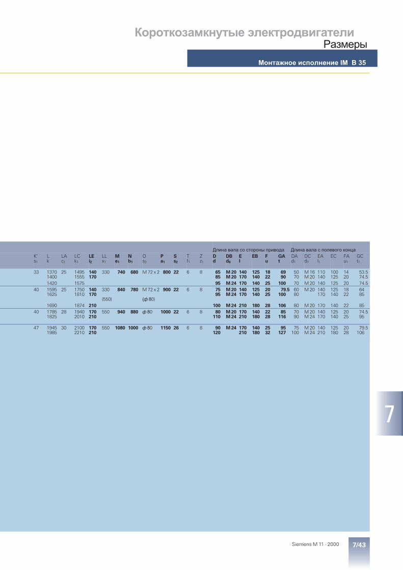
7/43Siemens M 11 · 2000
7
Короткозамкнутые электродвигателиРазмеры
Монтажное исполнение IM B 35
Длина вала со стороны привода Длина вала с полевого концаK’s1
Lk
LAc1
LCk1
LEi2
LLx1
Me1
Nb1
Os3
Pa1
Ss2
Tf1
Zz1
Dd
DBd6
EI
EB Fu
GAt
DAd1
DCd7
EAl1
EC FAu1
GCt1
33 13701400
25 14951555
140170
330 740 680 M 72 x 2 800 22 6 8 6585
M 20M 20
140170
125140
1822
6990
5070
M 16M 20
110140
100125
1420
53.574.5
1420 1575 95 M 24 170 140 25 100 70 M 20 140 125 20 74.540 1595
162525 1750
1810140170
330
(550)
840 780 M 72 x 2
(ф 80)
900 22 6 8 7595
M 20M 24
140170
125140
2025
79.5100
6080
M 20 140170
125140
1822
6485
1690 1874 210 100 M 24 210 180 28 106 80 M 20 170 140 22 8540 1785
182528 1940
2010170210
550 940 880 ф 80 1000 22 6 8 80110
M 20M 24
170210
140180
2228
85116
7090
M 20M 24
140170
125140
2025
74.595
47 19451985
30 21002210
170210
550 1080 1000 ф 80 1150 26 6 8 90120
M 24 170210
140180
2532
95127
75100
M 20M 24
140210
125180
2028
79.5106

8/1Siemens M 11 · 2000
8
8/2 Accessories
Spare parts8/3 1LA5 and 1MA5 · Frame sizes 56 M to 90 L8/4 1LA5 · Frame sizes 180 M to 225 M8/5 1LA7 and 1MA7 · Frame sizes 56 M to 90 L8/6 1LA7 and 1MA7 · Frame sizes 100 L to 160 L8/7 1LA6 and 1MA6 · Frame sizes 180 M to 200 L8/8 1LA6 and 1MA6 · Frame sizes 225 M to 315 L8/10 1LA8 and 1MA8 · Frame sizes 315 to 4508/12 1MJ6 · Frame sizes 71 M to 160 L
Squirrel-Cage MotorsAccessories and
Spare PartsSpare parts■ Siemens supply commitment for replacement
motors and spare parts for the followingperiods after delivery of the motor:
Up to 3 yrs a fully compatible motor –in terms of mounting dimensionsand functions – if the original motorfails completely (changes in seriesreserved).
Up to 5 yrs Spare parts.
Up to 10 yrs Technical advice about the com-plete motor and components;fabrication drawings for spare partssupplied if required.
■ The following information should be specifiedin all orders for spare parts:– Part designation and number– Order No. and Serial No. of the motor
Ordering example for a 1LA7 fan cowl,frame size 160 M, 4-pole:Fan cowl No. 7.40,1LA7 163–4AA60, Serial No. J783298901018
■ See Part 2 for bearing selection tables.
■ The 1UA7 COMBIMASTER comprises astandard 1 LA7 motor and a top-mountedfrequency converter. Spare parts for the motorshould be selected from the 1LA7 tables.The frequency converter can only be orderedas a complete unit (please inquire ).
■ Spare parts for 1MJ6 motors, frame size180 or larger, and 1MJ8, 1ME8, 1ML8 and1LG8 motors to order (please inquire).
No obligation exists to supply spares ofstandard parts.
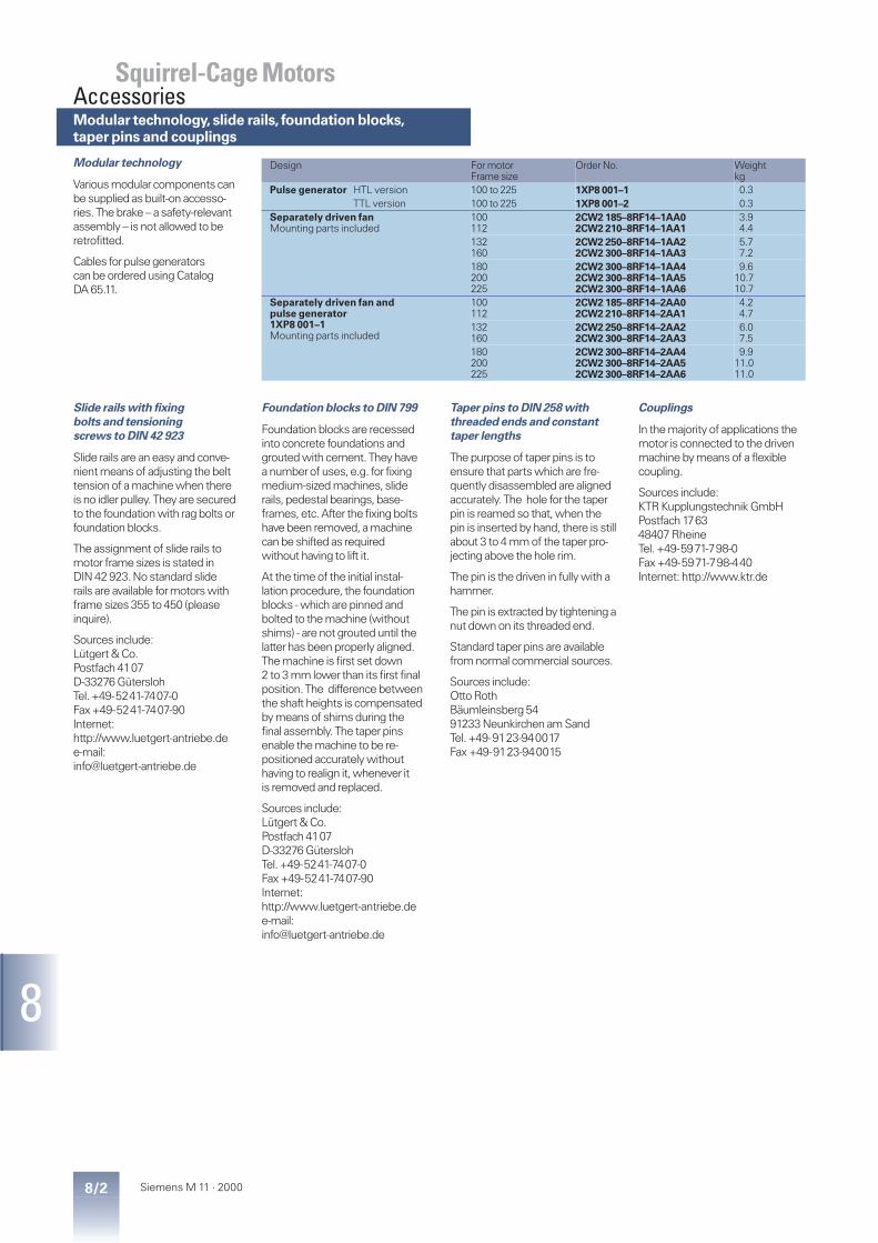
8/2 Siemens M 11 · 2000
8
Modular technology
Various modularcomponents canbe supplied as built-on accesso-ries. The brake – a safety-relevantassembly – is not allowed to beretrofitted.
Cables forpulse generatorscan be ordered using CatalogDA 65.11.
Design For motorFrame size
Order No. Weightkg
Pulse generator HTL version 100 to 225 1XP8 001–1 0.3TTL version 100 to 225 1XP8 001–2 0.3
Separately driven fanMounting parts included
100112
2CW2 185–8RF14–1AA02CW2 210–8RF14–1AA1
3.94.4
132160
2CW2 250–8RF14–1AA22CW2 300–8RF14–1AA3
5.77.2
180200225
2CW2 300–8RF14–1AA42CW2 300–8RF14–1AA52CW2 300–8RF14–1AA6
9.610.710.7
Separately driven fan andpulse generator1XP8 001–1Mounting parts included
100112
2CW2 185–8RF14–2AA02CW2 210–8RF14–2AA1
4.24.7
132160
2CW2 250–8RF14–2AA22CW2 300–8RF14–2AA3
6.07.5
180200225
2CW2 300–8RF14–2AA42CW2 300–8RF14–2AA52CW2 300–8RF14–2AA6
9.911.011.0
Slide rails with fixing
bolts and tensioning
screws to DIN 42 923
Slide rails are an easy and conve-nient means of adjusting the belttension of a machine when thereis no idlerpulley. They are securedto the foundation with rag bolts orfoundation blocks.
The assignment of slide rails tomotor frame sizes is stated inDIN 42 923. No standard sliderails are available formotors withframe sizes 355 to 450 (pleaseinquire).
Sources include:Lütgert & Co.Postfach 4107D-33276 GüterslohTel. +49-5241-7407-0Fax +49-5241-7407-90Internet:http://www.luetgert-antriebe.dee-mail:[email protected]
Foundation blocks to DIN 799
Foundation blocks are recessedinto concrete foundations andgrouted with cement. They havea numberof uses, e.g. for fixingmedium-sized machines, sliderails, pedestal bearings, base-frames, etc. After the fixing boltshave been removed, a machinecan be shifted as requiredwithout having to lift it.
At the time of the initial instal-lation procedure, the foundationblocks - which are pinned andbolted to the machine (withoutshims) - are not grouted until thelatterhas been properly aligned.The machine is first set down2 to 3 mm lower than its first finalposition. The difference betweenthe shaft heights is compensatedby means of shims during thefinal assembly. The taperpinsenable the machine to be re-positioned accurately withouthaving to realign it, whenever itis removed and replaced.
Sources include:Lütgert & Co.Postfach 4107D-33276 GüterslohTel. +49-5241-7407-0Fax +49-5241-7407-90Internet:http://www.luetgert-antriebe.dee-mail:[email protected]
Taper pins to DIN 258 with
threaded ends and constant
taper lengths
The purpose of taperpins is toensure that parts which are fre-quently disassembled are alignedaccurately. The hole for the taperpin is reamed so that, when thepin is inserted by hand, there is stillabout 3 to 4 mm of the taperpro-jecting above the hole rim.
The pin is the driven in fully with ahammer.
The pin is extracted by tightening anut down on its threaded end.
Standard taperpins are availablefrom normal commercial sources.
Sources include:Otto RothBäumleinsberg 5491233 Neunkirchen am SandTel. +49-9123-940017Fax +49-9123-940015
Couplings
In the majority of applications themotor is connected to the drivenmachine by means of a flexiblecoupling.
Sources include:KTR Kupplungstechnik GmbHPostfach 176348407 RheineTel. +49-5971-798-0Fax +49-5971-798-440Internet: http://www.ktr.de
Squirrel-Cage MotorsAccessoriesModular technology,slide rails, foundation blocks,taper pins and couplings
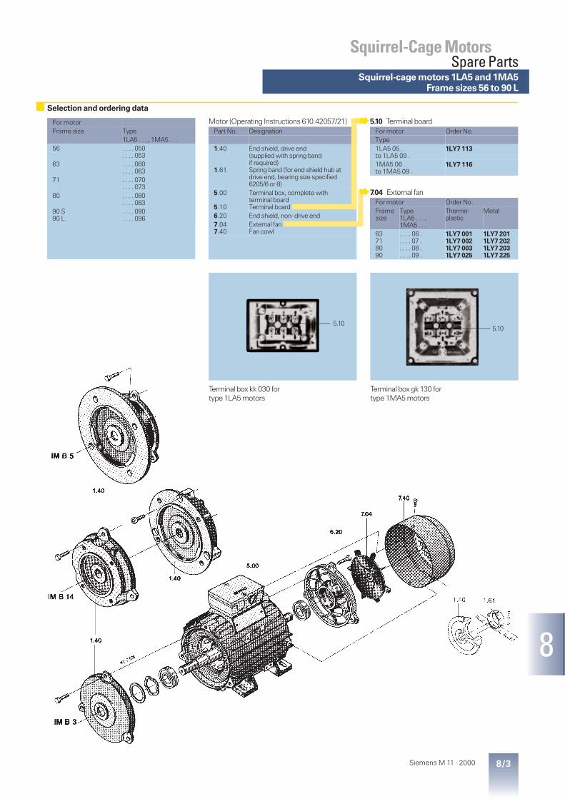
8/3Siemens M 11 · 2000
8
For motorFrame size Type
1LA5 . . . , 1MA5 . . .56 . . . . 050
. . . . 05363 . . . . 060
. . . . 06371 . . . . 070
. . . . 07380 . . . . 080
. . . . 08390 S90 L
. . . . 090
. . . . 096
Motor (Operating Instructions 610.42057/21)Part No. Designation
1.40
1.61
End shield, drive end(supplied with spring bandif required)Spring band (for end shield hub atdrive end, bearing size specified6205/6 or 8)
5.00
5.10
Terminal box, complete withterminal boardTerminal board
6.20 End shield, non- drive end7.047.40
External fanFan cowl
5.10 Terminal boardFor motor Order No.Type1LA5 05 .to 1LA5 09 .
1LY7 113
1MA5 06 .to 1MA5 09 .
1LY7 116
7.04 External fanFor motor Order No.Framesize
Type1LA5 . . . ,1MA5 . . .
Thermo-plastic
Metal
63718090
. . . . 06 .
. . . . 07 .
. . . . 08 .
. . . . 09 .
1LY7 0011LY7 0021LY7 0031LY7 025
1LY7 2011LY7 2021LY7 2031LY7 225
Terminal box kk 030 fortype 1LA5 motors
Terminal box gk 130 fortype 1MA5 motors
5.10
Squirrel-Cage MotorsSpare Parts
Selection and ordering data
Squirrel-cage motors 1LA5 and 1MA5Frame sizes 56 to 90 L
5.10

8/4 Siemens M 11 · 2000
8
For motorFrame size Type
180 M180 L
1LA5 1831LA5 186
200 L 1LA5 2061LA5 207
225 M 1LA5 2201LA5 223
Motor (Operating Instructions 610.42348/21)Part No. Designation
1.401.43/6.23
End shield, drive endV-ring
4.07 Frame feet (1 pair)5.00
5.10
Terminal box, complete withterminal boardTerminal board
6.20 End shield, non drive end7.047.40
External fanFan cowl
Terminal box gk 330 Terminal box gk 430
M1-
5093
5.10
1.401.43
4.07
6.20
7.04
7.40
6.23
5.00
5.10
Selection and ordering data
Squirrel-Cage MotorsSpare Parts
Squirrel-cage motors 1LA5 · Frame sizes 180 M to 225 M

8/5Siemens M 11 · 2000
8
For motorFrame size Type
1LA7 . . . . ,1MA7 . . . .
56 M . . . . 050. . . . 053
63 M . . . . 060. . . . 063
71 M . . . . 070. . . . 073
80 M . . . . 080. . . . 083
90 S90 L
. . . . 090
. . . . 096
Motor (Betriebsanleitung 610.43428/21)Part No. Designation
1.401.43/6.23
End shield, drive endV-ring
4.07 Frame feet (1 pair)5.00
5.10
Terminal box, complete withterminal boardTerminal board
6.20 End shield, non drive end7.047.40
External fanFan cowl
M1-
5173
1.40
IM B 5
IM B 14
1.40
IM B 3
1.43 4.07
5.00
5.10
6.23
6.20
7.04
7.40
Terminal box gk 030 fortype 1LA7 motors
5.10
Selection and ordering data
Squirrel-cage motors 1LA7 · Frame sizes 56 to 90
Squirrel-Cage MotorsSpare Parts
5.10 Terminal boardFor motor Order No.Type1LA7 05 .to 1LA7 09 .
1LY7 113
1MA7 06 .to 1MA7 09 .
1LY7 116
7.04 External fanFor motor Order No.Framesize
Type1LA7 . . . ,1MA7 . . .
Thermo-plastic
Metal
63718090
. . . . 06 .
. . . . 07 .
. . . . 08 .
. . . . 09 .
1LY7 0011LY7 0021LY7 0031LY7 025
1LY7 2011LY7 2021LY7 2031LY7 225
Terminal box gk 130 fortype 1MA7 motors
5.10
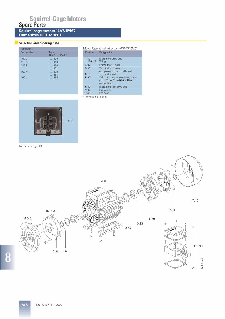
8/6 Siemens M 11 · 2000
8
For motorFrame size Type
1LA7 . . ., 1MA7 . . .100 L . . . . 106112 M . . . . 113132 S . . . . 130
. . . . 131160 M
160 L
. . . . 163
. . . . 164
. . . . 166
Motor (Operating Instructions 610.43428/21)Part No. Designation
1.401.43/6.23
End shield, drive endV-ring
4.07 Frame feet (1 pair)5.00
5.10
Terminal box cover*,complete with terminal boardTerminal board
5.90 Side-mounted terminal box, left orright ( Order Code K09 or K10respectively)
6.20 End shield, non drive end7.047.40
External fanFan cowl
* Terminal box is cast
Terminal box gk 130
M1-
5174
5.90
IM B 5
IM B 3
1.40 1.431.43
4.07
5.00
6.23
6.20
7.04
7.40
5.10
Selection and ordering data
Squirrel-Cage MotorsSpare PartsSquirrel-cage motors 1LA7/1MA7Frame sizes 100 L to 160 L

8/7Siemens M 11 · 2000
8
For motorFrame size Type
1LA6 . . . , 1MA6 . . .180 M180 L
. . . . 183
. . . . 186200 L . . . . 206
. . . . 207
Motor (Operating Instructions 610.43106/21)Part No. Designation
1.401.43/6.23
End shield, drive endV-ring
4.07 Frame feet (1 pair)5.00
5.10
Terminal box, complete withterminal boardTerminal board
6.20 End shield, non drive end7.047.40
External fanFan cowl
M1-
5093
5.10
1.401.43
4.07
6.20
7.04
7.40
6.23
5.00
Selection and ordering data
Squirrel-cage motors 1LA6 and 1MA6Frame sizes 180 M to 200 L
Squirrel-Cage MotorsSpare Parts

8/8 Siemens M 11 · 2000
8
For motorFrame size Type
1LA6 . . . , 1MA6 . . .225 S225 M
. . . . 220
. . . . 223250 M . . . . 253280 S280 M
. . . . 280
. . . . 283315 S315 M
. . . . 310
. . . . 313315 L . . . . 316
. . . . 317
. . . . 318
Motor (Operating Instructions NMA 2748 DE)Part No. Designation
5.005.10
End shield, drive endFlanged end shield
6.00 End shield, non drive end8.00 Rotor, complete with external fan
and roller bearing10.10 Frame feet (1 pair)11.00 External fan12.0112.70
Fan cowlCanopy
20.00 Terminal box, complete withterminals
Bearings (Operating Instructions NMA 2924 DE)Part No. Designation
4.204.60
Outer bearing cap, drive endInner bearing cap, drive end
3.203.603.10/4.10
Outer bearing cap, non-drive endInner bearing cap, non-drive endV-ring
Terminal box 1XB7 for frame sizes 225 Mto 400 L (Operating Instructions NMA 2923 DE)
Part No. Designation
20.30 Terminal box cover21.40 Insulating plate (terminal plate)
without terminals
Terminal box 1XB7 222and 1XB7 322
Terminal box 1XB7 422to 1XB7 622
21.40 21.40
Selection and ordering data
Squirrel-Cage MotorsSpare PartsSquirrel-cage motors 1LA6 and 1MA6Frame sizes 225 M to 315 L

8/9Siemens M 11 · 2000
8
Squirrel-cage motors 1LA6 and 1MA6Frame sizes 225 M to 315 L
Squirrel-Cage MotorsSpare Parts

8/10 Siemens M 11 · 2000
8
For motor
Frame size Type1LA8 . . . , 1MA8 . . .
315 . . . . 315. . . . 317
355 . . . . 353. . . . 355. . . . 357
400 . . . . 403. . . . 405. . . . 407
450 . . . . 453. . . . 455. . . . 457
Bearings (Operating InstructionsNMA 2934, 2935, 2936 DE)
Part No. Designation
3.203.60
Outer bearing cap, drive endInner bearing cap, drive end
4.204.603.10/4.10
Outer bearing cap, non-drive endInner bearing cap, non-drive endV-ring
Terminal box 1XB7 for frame sizes 315 and 355(Operating Instructions NMA 2923 DE)
Part No. Designation
20.30 Terminal box cover21.40 Insulating plate (terminal plate)
without terminals
Terminal box 1XB1 for frame sizes 400 and 450(Operating Instructions NMA 2937 DE)
Part No. Designation
20.00 Terminal box, complete20.30 Terminal box cover
Terminal post insulator
Terminal box 1XB7 622 Terminal box 1XB1 631
Motor(Operating Instructions NMA 3420 DE)
Part No. Designation
5.005.10
End shield, drive endFlanged end shield
6.00 End shield, non-drive end7.07 Internal fan8.00 Rotor, complete with external fan
and roller bearing11.0411.05
External fan, unidirectionalExternal fan, bidirectional
12.0112.70
Fan cowlCanopy
20.00 Terminal box, completewith terminals
21.40
Selection and ordering data
Squirrel-Cage MotorsSpare PartsSquirrel-cage motors 1LA8 and 1MA8Frame sizes 315 to 450

8/11Siemens M 11 · 2000
8
Squirrel-cage motors 1LA8 and 1MA8Frame sizes 315 to 450
Squirrel-Cage MotorsSpare Parts

8/12 Siemens M 11 · 2000
8
For motorFrame size Type
71 1MJ6 0701MJ6 073
80 1MJ6 0801MJ6 083
90 L 1MJ6 0961MJ6 097
100 L 1MJ6 1061MJ6 107
112 M 1MJ6 113132 S 1MJ6 130
1MJ6 131132 M 1MJ6 133
1MJ6 134160 M 1MJ6 163
1MJ6 164160 L 1MJ6 166
Motor (Operating Instructions 610.43413/21)Part No. Designation
1.401.441.64
End shield, drive endOuter bearing cap, drive end1)Inner bearing cap, drive end
4.07 Frame feet (1 pair)5.00
5.105.11
Terminal box, complete withexplosion-proof gland and terminalboardTerminal boardExplosion-proof gland
6.206.246.64
End shield, non-drive endOuter bearing cap, non-drive end1)Inner bearing cap, non-drive end
7.047.40
External fanFan cowl
1) In order to achieve compliance withthe IP 55 degree of protection, thebearing cap must always be fittedwith a matching shaft seal.
Selection and ordering data
Squirrel-Cage MotorsSpare Parts
Squirrel-cage motors 1MJ6 · Frame sizes 71 to 160 L

9/1Siemens M 11 · 2000
9
9/2 Environment, Resources and Recycling
9/2 Certificates
9/3 Packing Weights and Dimensions
9/4 Subject Index
9/6 Order No. Index
9/7 Siemens Companies and Representativesin Europe
9/8 Siemens Companies and RepresentativesWorldwide
9/10 Information and Ordering Facilitieson the Web and on CD-ROM
9/14 Conditions of Sale and Delivery
Squirrel-Cage MotorsAppendix
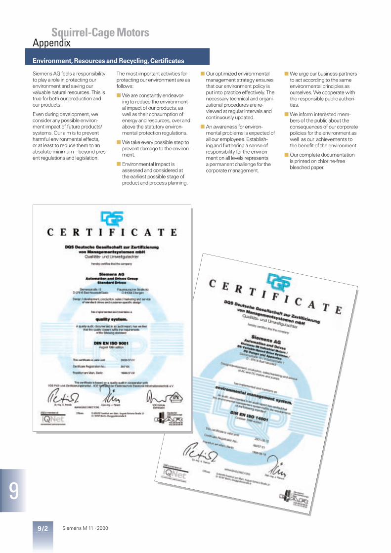
Environment,Resources and Recycling,Certificates
9/2 Siemens M 11 · 2000
9
Squirrel-Cage MotorsAppendix
Siemens AG feels a responsibilityto play a role in protecting ourenvironment and saving ourvaluable natural resources. This istrue for both our production andour products.
Even during development, weconsider any possible environ-ment impact of future products/systems. Our aim is to preventharmful environmental effects,or at least to reduce them to anabsolute minimum – beyond pres-ent regulations and legislation.
The most important activities forprotecting our environment are asfollows:
■ We are constantly endeavor-ing to reduce the environment-al impact of our products, aswell as their consumption ofenergy and resources, over andabove the statutory environ-mental protection regulations.
■ We take every possible step toprevent damage to the environ-ment.
■ Environmental impact isassessed and considered atthe earliest possible stage ofproduct and process planning.
■ Our optimized environmentalmanagement strategy ensuresthat our environment policy isput into practice effectively. Thenecessary technical and organi-zational procedures are re-viewed at regular intervals andcontinuously updated.
■ An awareness for environ-mental problems is expected ofall our employees. Establish-ing and furthering a sense ofresponsibility for the environ-ment on all levels representsa permanent challenge for thecorporate management.
■ We urge our business partnersto act according to the sameenvironmental principles asourselves. We cooperate withthe responsible public authori-ties.
■ We inform interested mem-bers of the public about theconsequences of our corporatepolicies for the environment aswell as our achievements tothe benefit of the environment.
■ Our complete documentationis printed on chlorine-freebleached paper.

Environment,Resources and Recycling
9/3Siemens M 11 · 2000
9
Squirrel-Cage MotorsAppendix
The figures stated in this tableapply to individual packing.Frame sizes 56 to 180 L canalso be packed on grid crates.Order Code L99.
Packing weights for type 1LA, 1MA and 1MJ motors
For motors For land transportFramesize
Type1LA5 . . ./1LA7 . . .,1LA6 . . ., 1LA9 . . .,1MA6 . . ., 1MA7 . . .,1MJ6 . . .
Type of construction IM B 3 Types of construction IM B 5 , IM V 1incartons
onbattens
incrates
incartons
onbattens
incrates
tare tare tare tare tare tarekg kg kg kg kg kg
56 . . . . 050/053 0.65 – – 0.65 – –63 . . . . 060/063 0.65 – – 0.65 – –71 . . . . 070
. . . . 0730.65 – – 0.65 – –
80 . . . . 080. . . . 083
0.65 – – 0.65 – –
90 S90 L
. . . . 090
. . . . 096/0970.65 – – 0.65 – –
100 L . . . . 106/107 1.3 – – 1.3 – –112 M . . . . 113 1.5 – – 1.5 – –132 S132 M
. . . . 130/131
. . . . 133/1344.7 – – 5.2 – –
160 M160 L
. . . . 163/164
. . . . 1664.8 – – 5.7 – –
180 M180 L
. . . . 183
. . . . 18613.0 – – 13.4 – –
200 L . . . . 206/207 13.5 – – 13.5 – –225 S225 M
. . . . 220
. . . . 22313.7 7 20 13.7 10 20
250 M . . . . 253 – 20 36 – 20 40280 S280 M
. . . . 280
. . . . 283– 20 36 – 20 40
315 S315 M315 L
. . . . 310
. . . . 313
. . . . 316/317/318
– 20
22
38
40
– 20
22
45
For 1LG8 motors
90 S/ L 2 – – 2 – –100 L 2 – – 3 – –112 M 3 – – 4 – –132 S/ M 4 – – 6 – –160 M/ L – 8 – – 8 –
Values for type 1MJ8 motorson request.
Packing weights and dimensions for 1LA8 and 1MA8 motors
For motors Packing weightsFramesize
Type1LA8 . . .,1MA8 . . .
Land transport on battens Sea transport in wooden casesType IM B 3 Type IM V 1 Type IM B 3 Type IM V 1tare tare tare tarekg kg kg kg
315355400450
. . . . 315/317
. . . . 353/355/357
. . . . 403/405/407
. . . . 453/455/457
30404550
55657585
270320390450
310365445510
Maximummotor dimensions
Allowances for maximum motor dimensions(packing dimensions = motor dimensions + allowance)Land transport on battens Sea transport in wooden casesType IM B 3 Type IM V 1 Type IM B 3 Type IM V 1approx. approx. approx. approx.mm mm mm mm
LengthWidthHeight
+250+200+200
+250+300+250
+250+200+500
+250+200+500
Subject Index
9/4 Siemens M 11 · 2000
9
Squirrel-Cage MotorsAppendix
PageA
Accessories Part 8Aluminum enclosure 3/2Anti-condensation heater 2/15Ambient temperature 2/8Axial loads 2/33
B
Balance quality 2/32Basic design Part 3Bearings 2/24Bearing arrangements 2/27Bearings for high cantilever forces 2/30Brake 2/38
C
CA 01 9/12Canada 2/3Cantilever forces, maximum 2/29Cast-iron enclosure 3/12CD-ROM 9/12CEMEP 2/4, 3/2, 3/12Certificates 9/2Certification 3/27, 4/6, 5/6, 6/7Class EMC filters 4/1 to 4/5COMBIMASTER Part 4Converter-fed operation 3/21Cooling and ventilation 2/16Couplings 8/2Coupling to gearboxes 2/16Commissioning notes 3/27Conditions of sale and delivery 9/14Converter mounting 3/26CSA 2/3
D
Degrees of protection 2/15Dimensions Part 7Direction of rotation 2/16DURIGNIT IR 2000 2/14
E
EEx de IIC type of protection Part 6EEx e II type of protection Part 5eff1 2/4, 3/4, 3/16eff2 2/4, 3/2, 3/12Efficiency 2/9Electrical data Part 2Electrical tolerances 2/3EMC filters 4/1 to 4/5Energy-saving motors to CEMEP 2/4, 3/2, 3/12Energy-saving motors to EPACT 3/6, 3/17Environment, resources and recycling 9/2EPACT 3/6, 3/17Explosion-proof enclosure/EEx de IIC type of protection Part 6Eyebolts 2/15
F
Filter, EMC 4/1 to 4/5Foundation blocks 8/2Frame design 2/15Frequency 2/5
PageG
General data Part 2
H
Hazardous areas 2/4High Efficiency eff1 2/4, 3/4, 3/16
I
Improved Efficiency eff2 2/4, 3/2, 3/12Increased output 3/8Increased cantilever forces 2/30Increased safety EEx e II type ofprotection Part 5Information and ordering facilitieson the Web and on CD-ROM 9/10Insulation with DURIGNIT IR 2000 2/14Introduction 1/2
L
Low-noise design 2/17
M
Maximum axial load 2/33Maximum cantilever forces 2/29Mechanical data Part 2Mechanical features 3/27, 4/6, 5/6, 6/7Mechanical balance quality 2/32Modular technology 2/36, 3/25, 4/6, 8/2Motor connection 2/18Motor protection 2/14, 3/25, 4/6, 5/5, 6/6Motors for converter-fed operation 3/21Motors for duty at SIMOVERTMASTERDRIVES 3/22Motors for the U.S. market 2/3, 3/6, 3/17Motors with converters 4/1Motor temperature detection forconverter-fed operation 2/14Mountings 2/36, 3/26, 4/6, 8/2Mounting technology 2/36, 3/26, 4/6, 8/2
N
National standards 2/3NEMA 2/3Noise 2/17
O
Order Codes for special designs 3/25, 4/6, 5/5, 6/6Ordering data Parts 3 to 6Ordering example 2/2Order No. 2/2Order number structure 2/2Order numbers, index of 9/6Output 2/8Outputs at 60 Hz 2/7
P
Packing weights and dimensions 9/3Paint finish 2/35, 3/25, 4/6, 5/5, 6/6Pole-changing 3/9, 3/18Pole-changing for driving fans 3/10, 3/19Power factor 2/9PTC thermistor 2/14Pulse generator 2/36

9/5Siemens M 11 · 2000
9
Squirrel-Cage MotorsAppendix
Subject index
PageR
Rated currents at voltagesbetween 380 V and 420 V 2/6Rated torque 2/9Rating plate 2/8Representations of Siemens 9/7Restarting against residual field andopposite phase 2/14
S
Safety and commissioning notes 3/27Selection and ordering data Parts 3 to 6Selection of bearings 2/25Separately-driven fan 2/36Shaft extensions 2/32SIMOVERT MASTERDRIVES 3/21Slide rails 8/2Spare parts Part 8Special designs 3/25, 4/6, 5/5, 6/6Specifications 2/3Speed 2/16Spring-operated disk brake 2/38Standards 2/3Standards and specifications 2/3
PageT
Taper pins 8/2Temperature classes 2/4, 5/1 to 5/4,
6/1 to 6/5Temperature sensor 2/14Terminal boxes 2/18, Part 8Torque 2/9Torque characteristics 2/10Types of construction 2/22
U
USA 2/3
V
Ventilation 2/16Versions for Zones 3/26Vibration severity 2/32VIK design 2/4Voltage 2/5Voltage and frequency 2/5
W
Winding and motor protection 3/25, 5/5World Wide Web 9/10
Z
Zone 2 2/4Zone 21 2/4Zone 22 2/4

9/6 Siemens M 11 · 2000
9
Squirrel-Cage MotorsAppendix
Index of Order Numbers
Order No. Page
1LA5 18 . 3/2, 3/3, 3/9 to 3/111LA5 20 . 3/2, 3/3, 3/9 to 3/111LA5 22 . 3/2, 3/3, 3/9
1LA6 18 . 3/12 to 3/15, 3/191LA6 20 . 3/12 to 3/15, 3/191LA6 22 . 3/12 to 3/20, 3/23, 3/241LA6 25 . 3/12 to 3/20, 3/23, 3/241LA6 28 . 3/12 to 3/20, 3/23, 3/241LA6 31. 3/12 to 3/18, 3/23, 3/24
1LA7 05 . 3/21LA7 06 . 3/2, 3/3, 3/91LA7 07 . 3/2, 3/3, 3/91LA7 08 . 3/2, 3/3, 3/9, 3/101LA7 09 . 3/2, 3/3, 3/9 to 3/111LA7 10 . 3/2, 3/3, 3/9 to 3/111LA7 11 . 3/2, 3/3, 3/9 to 3/111LA7 13 . 3/2, 3/3, 3/9 to 3/111LA7 16 . 3/2, 3/3, 3/9 to 3/11
1LA8 31 . 3/12 to 3/15, 3/22 to 3/241LA8 35 . 3/12 to 3/15, 3/22 to 3/241LA8 40 . 3/12 to 3/15, 3/22 to 3/241LA8 45 . 3/12 to 3/15, 3/22 to 3/24
1LA9 05 . 3/4 to 3/81LA9 06 . 3/4 to 3/81LA9 07 . 3/4 to 3/81LA9 08 . 3/4 to 3/81LA9 09 . 3/4 to 3/81LA9 10 . 3/4 to 3/81LA9 11 . 3/4 to 3/81LA9 13 . 3/4 to 3/81LA9 16 . 3/4 to 3/81LA9 18 . 3/4 to 3/81LA9 20 . 3/4 to 3/8
1LG8 09 . 3/12 to 3/15, 3/191LG8 10 . 3/12 to 3/15, 3/191LG8 11 . 3/12 to 3/15, 3/191LG8 13 . 3/12 to 3/15, 3/191LG8 16 . 3/12 to 3/15, 3/19
1LY7 . . . 8/3
Order No. Page
1MA6 18 . 5/2 to 5/41MA6 20 . 5/2 to 5/41MA6 22 . 5/2 to 5/41MA6 25 . 5/2 to 5/41MA6 28 . 5/2 to 5/41MA6 31 . 5/2 to 5/4
1MA7 06 . 5/2, 5/31MA7 07 . 5/2 to 5/41MA7 08 . 5/2 to 5/41MA7 09 . 5/2 to 5/41MA7 10 . 5/2 to 5/41MA7 11 . 5/2 to 5/41MA7 13 . 5/2 to 5/41MA7 16 . 5/2 to 5/4
1MA8 31 . 5/2 to 5/41MA8 35 . 5/2 to 5/4
1MJ6 07 . 6/2 to 6/41MJ6 08 . 6/2 to 6/41MJ6 09 . 6/2 to 6/51MJ6 10 . 6/2 to 6/51MJ6 11 . 6/2 to 6/51MJ6 13 . 6/2 to 6/51MJ6 16 . 6/2 to 6/51MJ6 18 . 6/2 to 6/51MJ6 20 . 6/2 to 6/51MJ6 22 . 6/2 to 6/51MJ6 25 . 6/2 to 6/51MJ6 28 . 6/2 to 6/51MJ6 31 . 6/2 to 6/51MJ8 31 . 6/2 to 6/51MJ8 35 . 6/2 to 6/51MJ8 40 . 6/2 to 6/51MJ8 45 . 6/2 to 6/5
1UA7 05 . 4/2, 4/31UA7 06 . 4/2 to 4/51UA7 07 . 4/2 to 4/51UA7 08 . 4/2 to 4/51UA7 09 . 4/2 to 4/51UA7 10 . 4/2 to 4/51UA7 11 . 4/2 to 4/51UA7 13 . 4/2 to 4/5
1XB1 . . . 8/101XB7 . . . 8/8, 8/10
2CW2 . . . 8/2

9/7Siemens M 11 · 2000
9
Squirrel-Cage MotorsAppendix
Siemens Companies and Representatives in Europe
AlbaniaBINDI sh. p. k.Tirana
ArmeniaRepresentative of Siemens AGYerevan
AustriaSiemens AG ÖsterreichViennaBregenzDeutschlandsbergEisenstadtGrazInnsbruckKlagenfurtKlosterneuburgLinzSalzburgSt. PöltenVillach
AzerbaijanRepresentative of SIMKO ASBaku
BelarusRepresentative of Siemens AGMinsk
BelgiumSiemens S. A.BrusselsAntwerpenBoussuColfontaineDilsen-StokkemGentHaasrodeHerentalsHuizingenLiègeNamurOostkampZaventem
BulgariaSiemens AG Representative in BulgariaSofia
CroatiaSiemens d.d.Zagreb
CyprusGEVO Ltd.Nicosia
Czech RepublicSiemens s.r.o.PragueBrnoDinínSthíbroTrutnov
DenmarkSiemens A/SBallerupAlborgBrønshøjEsbjergHedenstedHøjbjergOdenseSkensvedTåstrupVejle
Eire (Ireland)Siemens Ltd.Dublin
EstoniaAS SiemensTallinn
FinlandSiemensOsakeyhtiöEspooHelsinki
FranceSiemens S. A. S.Saint-DenisBihorelCaluire-et-CuireCesson SévignéDijonHaguenauLa Garenne ColombesLa-Suze-sur-SartheLesquinLes UlisLissessLormontMarseilleMérignacMetzMontrougeMolsheimNanterreNantesNicePantinParis La DéfenseReimsSaint-DenisSaint-QuentinStrasbourgToulouse
GeorgiaRepresentative of Siemens AGTbilisi
Great BritainSiemens plcBracknellBeestonBelfastBellshillBirminghamBristolCamberleyCambridgeChessingtonChristchurchClevedonCorbyCongletonCrawleyCumbernauldEast KilbridgeFarehamGlasgowHemel HempsteadHounslowIlfordIsle of WightLondonLutonManchesterMilton KeynesNewcastle-upon-TyneOldhamOxfordPoolePurleyRomseyTelfordWellingboroughWembley
GreeceSiemens A. E.Athen, AmaroussioAcharnesThessalonikiVassiliko Evias
HungarySiemens Rt.BudapestBicskeCegledSzombathely
IcelandSmith & Nordland HFReykjavik
ItalySiemens S. p. A.MilanoBariBolognaBresciaCagliariCasoriaCassina de PecchiFangliaFirenzeGenovaNapoliPadovaPalermoPescaraRomaTorinoVerona
LatviaSiemens S/ARiga
LithuaniaLietuvos ELTIKAVilniusKlaipeda
LuxembourgSiemens S. A.Luxembourg-Hamm
MacedoniaSITAI d.o.o.Skopje
MaltaJ.R.D. SYSTEMS Ltd.Harun
MoldaviaSiemens s.r.l.Chisinau
NetherlandsSiemens Nederland N. V.Den HaagAlphen a/d RijnZoetermeer
NorwaySiemens A/SOsloFyllingsdalenTrondheim
PolandSiemens Sp.z.o.o.WarsawGdañsk-WrzeszczKatowiceKratówPoznapWroclaw
PortugalSiemens S. A.LisbonAmadoraAlbufeiraCarnaxideCoimbraEvoraLouresMatosinhos CodexMem MartinsSeixal
RomaniaSiemens birou de consultaTii tehniceBucharestSlatina
RussiaSiemens GmbH MoskauMoscowBarnaulJakutskYekaterinburgIrkutskYshewskKalugaKrasnodarNovosibirskPermSt. PetersburgTbilissiTjumenTomskUfaVladivostok
Slovak RepublicSiemens s.r.o.BratislavaDolný KubinHorná StredaMichalovceNitraNové ZámkyTrnava
SloweniaSiemens d.o.o.LjubljanaKranjMaribor
SpainSiemens S. A.BilbaoCornellá de LlobregatGijoñLa CoruñaLas Palmas de Gran CanariaLeónMálagaMurciaPalma de MallorcaSanta Cruz de TenerifeSevillaTres Cantos (Madrid)ValenciaVallodolidVigoZaragoza
SwedenSiemens ABUpplands VäsbyGöteborgHaningeJönköpingKistaMalmöSolnaSundsvall
SwitzerlandSiemens Schweiz AGZürichAdliswilBaselBioggioBronschhofenDietikon-FahrweidFahrweidWinterthur-Töss
TurkeySIMKO Ticaret ve Sanayi A.S.Findikli IstanbulAdanaAlsancak-IzmirAyazag-IstanbulBexiktax-IstanbulBursaCerkezköy-TekikdagKartal-IstanbulKavaklidere-AnkaraMecidiyeköy-IstanbulMudanyaSamsun
UkraineRepresentative of Siemens AGKiewCharkiwOdessaWischgorod
YugoslaviaSiemens d.o.o.Beograd
9/8 Siemens M 11 · 2000
9
Squirrel-Cage MotorsAppendix
Siemens Companies and Representatives Worldwide
Africa
AlgeriaSiemens Bureau d’AlgerHydra
AngolaEscritório de Representacão da Siemensem AngolaLuanda
BotswanaSiemens (Pty) Ltd.GaboroneIwaneng
CongoSOFAMATEL S.P.R.L.Kinshasa
Côte d’IvoireSiemens AGS.A.R.L.Abidjan
EgyptSiemens LimitedCairo-MohandessinSmouha Alexandria
CentechCairo-Zamalek
EthiopiaSiemens (Pvt)Addis Abeba
GhanaImpromex ACCRAAccra
GuineaAndré & Cie. S. A.Lausanne
KenyaSiemens Communications Ltd.Nairobi
LesothoRange Telecommunication Systems (Pty)LtdMaseru
LibyaSiemens A. G. Branch LibyaTripoli
MalawiEcolectric Ltd.Blantyre
MauritiusIreland Blyth LtdPort Louis
MoroccoSETELSociété Electrotechniqueet de Télécommunication S. A.Casablanca
MosambiqueSiemens LimitadaMaputo
NamibiaSiemens (Pty.) Ltd.Windhoek
NigeriaSiemens LimitedLagosAbujaKaduna
Republic of South AfricaSiemens Ltd.Halfway HouseCenturionIsandoPretoriaSpringsWoodmead
SudanNational ElectricalCommercial Co.Khartoum
SwazilandSiemens (Pty) LtdMatsapha
TansaniaTanzania Electrical Services Ltd.Dar-es-Salaam
TunesiaSiemens Bureau de LiaisonTunis
ZambiaSiemens (Z) Ltd.KitweLusaka
ZimbabweSiemens (Pvt.) Ltd.HarareAlexandra Park
America
ArgentinaSiemens S. A.Buenos AiresSan MartinBahia BlancaCórdobaLas HerasMar del PlataRosarioBoulogne sur Mer
BoliviaSociedad Comercial é Industrial HansaLtda.La Paz
BrazilSiemens Ltda.Sao PauloBelo HorizonteBrasiliaCampinasCuritibaFlorianópolisFortalezaFravataiJaboatao dos GuararapesJundiaiManausPôrto AlegreRibeirao PretoRio de JaneiroSaltoSalvadorS. Bernado do CampoVila Sao Joao
CanadaSiemens Canada LimitedMississangaAjaxBramptonBurnabyCalgaryCambridgeClathamDartmouthDrummondvilleEdmontonKanataLondonMonctonMontrealMount PearlOttawaPointe ClaireSaçkatoonSherbrookeTilburyVanierWindsorWinnipeg
ChileSiemens S.A.Santiago de Chile
ColombiaSiemens S. A.Santafé de BogotáBarranquillaCali-OccidenteMedellin
Costa RicaSiemens S. A.San José
CubaEUMEDARepresentación Consultiva de SiemensElectromedicinaCiudad de la Habana
CuraçaoSANTRACO N. V.Willemstad
Dominican RepublicElectromédica S. A.Santo Domingo
EcuadorSiemens S. A.QuitoGuayaquil
El SalvadorSiemens S. A.San Salvador
GuatemalaSiemens S. A.Ciudad de Guatemala
HondurasRepresentaciones ElectroindustrialesS. de R.L.San Pedro SulaTegucigalpa
JamaicaMeditron Ltd.Kingston
MartiniquePérié MedicalFort-de-France
MexicoSiemens S A de CVMéxico, D.F.AguascalientesApodacaChihuahuaCd. JuárezCuliacánGómez PalacioHermosilloLeónMéridaPueblaSan Juan CuautlancingoTijuanaTlajomulco de ZunigaVeracruzVilla Corregidora
NicaraguaSiemens S. A.Managua
PanamaSiemens S. A.Panama
ParaguayRieder & Cia. S. A. C. I.Asunción
PeruSiemens S. A.Lima
Trinidad and TobagoBiomedical Technologies Ltd.St. Augustin
United States of AmericaSiemens CorporationNew YorkAllentownAlpharettaArlingtonAtlantaAuburn HillsBoca RatonBridgewaterBrooklyn ParkCamarilloCharlotteColumbusConcordCupertinoDanversDuluthFountain InnGainsvilleHickoryHoffman EstatesIssaguahIselinJohnson CityLake OswegoLimaMilwaukeeNewport NewsNorcrossOklahoma CityPalo AltoPiscatawayPrincetonRichardsonRichlandSacramentoSanta ClaraSanta Fe SpringsSan JoseSunnyvaleTotawaWashingtonWendell
UruguayConatel S.A.Montevideo
VenezuelaSiemens S. A.CaracasBarcelonaMaracaiboPerto OrdazValencia

9/9Siemens M 11 · 2000
9
Squirrel-Cage MotorsAppendix
Siemens Companies and Representatives Worldwide
Asia
BahrainSiemens AG Service CenterTransitec GulfManama
BangladeshSiemens Bangladesh Ltd.DhakaKhulna
BruneiAMS TechnologiesSdn BhdNegaraBruneiDarussalam
IndiaSiemens Ltd.AhmedabadBangaloreCalcuttaChandigarhChennaiCoimbatoreGurgaonKaloorMumbaiNashikNavi MumbaiNew DehliPuneSecunderabadVadodara
IndonesiaRepresentative Office Siemens AGJakartaBatamCilegonSurabaya
IraqSiemens AGBaghdad
IranSiemens S.S.K.Teheran
IsraelSiemens Ltd.Tel AvivHolonHerzeliyaRamat Hakhaiyal
JapanSiemens K. K.TokyoKobeFukuokaHiroshimaIshikawaKanagawaNagoyaOsakaSapporoSendaiYokohama
JordanSiemens AGJordan BranchShmeisani-AmmanAmman
KazakhstanRepresentative of Siemens AGAlmaty
KirghizstanRepresentative of Siemens AGBischkek
Korea (Republic)Siemens Ltd.SeoulChangwonKyungki-Do
KuwaitNational & German Electrical andElectronic Services Co.(NGEECO)Kuwait
LebanonSiemens AG Lebanon BranchBeyrouth
MalaysiaSiemens ElectricalEngineering Sdn. Bhd.Petaling JayaKuala LumpurKajang
MyanmarSiemens Ltd.Yangon
NepalAmatya Enterprises (Pvt.) Ltd.Kathmandu
OmanSiemens AGMuscat BranchRuwiMuscat
PakistanSiemens PakistanEngineering Co. Ltd.KarachiFaisalabadIslamabadLahorePeshawarQuetta
People’s Republic of ChinaSiemens Ltd., ChinaBeijingChangchunChengduChongqingChuzhouDalianFuqingFuzhouGuangzhouHangzhouJilinJinanNanhaiNanjingPanyuRizhaoShanghaiShenyangShenzhenSuzhouTianjinWuhanWuxiXi’anXiaogan CityZibo
PhilippinesSiemens Inc.Makati CityPasig CityCebuDavao City
QatarArabian ConstructionEngineering CompanyDoha
Saudi ArabiaArabia Electric Ltd. (Equipement)JeddahAl KhobarRiyadh
SingaporeSiemens Advanced Engineering (Pte.) Ltd.Singapore
Sri LankaDimo LimitedColombo
SyriaSiemens AGDamascus BranchDasmascus
TaiwanSiemens Ltd.TaipeiTaichungKaohsiungTaoyuan Hsien
ThailandSiemens LimitedBangkokRayong
TurkmenistanRepresentative of Siemens AGAschgabad
UzbekistanRepresentative of Siemens AGTaschkent
United Arab EmiratesSiemens Resident EngineersDubaiAbu Dhabi
VietnamSiemens AG RepresentationHanoiHo Chi Minh City
YemenTihama Tractors & Engineering Co. Ltd.SanaaAden
AustraliaSiemens Ltd.MelbourneAdelaideBayswaterBrisbaneGladesvilleMiltonPennant HillsPerthSilverwaterSt. LeonardsSydney
New ZealandSiemens (NZ) LimitedAucklandWellington

9/10 Siemens M 11 · 2000
9
Squirrel-Cage MotorsAppendix
Information and Ordering with A&D
A&D on the Web
A detailed knowledge of therange of products and servicesavailable is essential when plan-ning and configuring automationsystems. It goes without sayingthat this information must alwaysbe fully up-to-date.
The Siemens Automation andDrives Group (A&D) has thereforebuilt up a comprehensive range ofinformation in the World WideWeb, which offers quick and easyaccess to all data required.
Under the address
http://www.ad.siemens.de
you will find everything you needto know about products, systemsand services.
Product selection using the Interactive Catalogs
Detailed information togetherwith convenient interactivefunctions:The interactive catalogs CA 01 andET 01 cover more than 80,000products and thus provide a fullsummary of the Siemens Auto-mation & Drives product base.
Here you will find everything thatyou need to solve tasks in thefields of automation, switchgear,installation and drives. All informa-tion is linked into a user interfacewhich is easy to work with andintuitive.
After selecting the product of yourchoice you can order at the pressof a button or by fax or by onlinelink.
Information on the interactivecatalogs can be found in theInternet under
http://www.ad.siemens.de/ca01
or on CD-ROM:
Automation and Drives, CA 01Order No.:E86060-D4001-A110-B3-7600
Electrical installationtechnology, ET 01Order No.:E86060-D8200-A107-A1
Easy Shopping with the Siemens Mall
The Siemens Mall is the virtualdepartment store of Siemens AGin the Internet. Here you have ac-cess to a huge range of productspresented in electronic catalogs inan informative and attractive way.
The Siemens Mall allows thewhole procedure from selectionthrough ordering to tracking of theorder to be carried out online viathe Internet.
Numerous functions are availableto support you.For example, powerful searchfunctions make it easy to find
the required products, which canbe immediately checked for avail-ability. Customer-specific dis-counts and preparation of quotescan be carried out online as wellas order tracking and tracing.Please visit the Siemens Mallon the Internet under:
http://mall.siemens.de
9/11Siemens M 11 · 2000
9
Squirrel-Cage MotorsAppendix
Notes

9/12 Siemens M 11 · 2000
9
Squirrel-Cage MotorsAppendix
Notes

9/13Siemens M 11 · 2000
9
Squirrel-Cage MotorsAppendix
Notes
9/14 Siemens M 11 · 2000
9
Squirrel-Cage MotorsAppendix
Conditions of Sale and Delivery
Outside Germany
Subject to the General Conditionsof Sale and Delivery for Productsand Services of the Electrical andElectronic Industry and to anyother conditions agreed upon withthe recipients of catalogs.
■The technical data, dimensionsand weights are subject to changeunless stated otherwise on indi-vidual pages of this catalog.
The illustrations are for referenceonly.
We reserve the right to adjust theprices and shall charge the pricesapplying of delivery.
Important:
The technical specifications con-tained in this catalog are providedas general information.The Operating Instructions andthe information specified on theactual products are binding forinstallation, operation andmaintenance.
â COMBIMASTER, DURIGNIT,SIMOVERT are registered trade-marks of Siemens.Other designations used in thiscatalog may be trademarkswhose use by third parties fortheir own purposes could violatethe rights of the owners.
Á All dimensions in this catalogare stated in millimetres.
Issued by: Siemens Aktiengesellschaft AGAutomation and Drives Group (A&D)Standard DrivesP.O. Box 3269, D-91050 ErlangenGermanyhttp://www.ad.siemens.de
Responsible for
Technical contents:Siemens AG, A&D SD VM,Erlangen, Germany
General editing:Siemens AG, A&D PT 5,Erlangen, Germany
Order No.: E86060–K1711–A101–A1–7600Printed in the Federal Republic of GermanyKG K 0900 25.0 E 176 En/022448