low voltage products low voltage current transformers type ...204a... · low voltage current...
TRANSCRIPT

Low voltage current transformerstype: IMW, IMP, IMS, ISW, INSOA, IMR
Low voltage products
2 Low voltage current transformers
Low voltage current transformerstype: IMW, IMP, IMS, ISW, INSOA, IMR
INDEXGeneral informationApplication .........................................................................................3Operating conditions ........................................................................3Design ................................................................................................3Mounting ............................................................................................3Packing, transport, storage ..............................................................4Spare parts ........................................................................................4Compliance with standards .............................................................4Warranty ............................................................................................4Handling used products ...................................................................4Submitting an order ..........................................................................4Example of an order .........................................................................4Transformer selection .......................................................................5Technical data, dimensional drawingsTransformers type IMW with primary winding ................................6Transformers type IMS on busbarIMSa ...................................................................................................8IMSb ................................................................................................10IMSc .................................................................................................12IMSd ................................................................................................14Transformers type IMP on cableIMPa .................................................................................................16IMPb .................................................................................................18Transformers type ISW on busbar or cableISWb ................................................................................................20ISWb2 ..............................................................................................22ISWc ................................................................................................24ISWd1 ..............................................................................................26ISWd2 ..............................................................................................28ISWe ................................................................................................30ISWf .................................................................................................32ISWg ................................................................................................34ISWh1 ..............................................................................................36ISWh2 ..............................................................................................38Transformers type IMR to switchgearIMR0 ................................................................................................40IMR1a ..............................................................................................42IMR1b ..............................................................................................44IMR2 ................................................................................................46Special transformers INSOA ..........................................................48AccessoriesVoltage terminal ..............................................................................50Support for mounting transformer on a TS35 mounting busbar ..........................................................50Busbar mounting assembly ...........................................................50Standard bolt with holder for a 30 mm or 60 mm busbar ................50Copper sleeve .................................................................................50Busbars ...........................................................................................51Transformer selection table ...........................................................52Primary current range .....................................................................56 Certificates ......................................................................................56

Low voltage current transformers 3
General information
APPLICATIONLow voltage current transformers are intended for supplying meas-uring instruments and protection circuits of electrical power devices with a maximum operating voltage of 0.72 kV and frequency of 50 Hz (or 60 Hz after prior arrangement with the manufac-turer). Transformers of power utility installations. The transformers are manufactured for secondary currents 1A and 5A. The range of primary currents depends on the transformer and can range from 1 A up to 6,000 A.
OPERATING CONDITIONSThe transformers are designed for operation in indoor equip-ment in climatic conditions: temperate (N3) or tropical (T3). The long–term thermal rated current and limits of deviations of these transformers correspond to an extended current range of 120% of Ipn within the ambient temperature range from 248 K (-25°C) to 328 K (+55°C). It is possible to produce some transformers with a 150% or 200% current range by special arrangement with the manufacturer.
DESIGNThe low voltage current transformers are single-phase, low power transformers, operating in quasi short-circuit conditions and trans-forming the current flowing through the primary circuit to the current in the secondary circuit with a level of accuracy specified in relevant standards. Their insulation class is E or A. The windings of the cur-rent transformers are enclosed in the housings made of heat and fire resistant material.The current transformers are produced for different types of primary circuits: busbar or cable according to the transformer selection table (page 52). The range of primary currents is from 1 A up to 6000 A. Transformer types: IMW, IMP, IMS, IMR2 and ISW (with the exception of ISWc) have offer the option of a sealing cover for
secondary termianals. Transformers are permanently marked with the rated ratio on both sides of the casing. They have slides allow-ing assembly to the base and screws or holder for mounting on the current circuit. Equipment details are stated in the transformer selection table (page 52).
MOUNTINGLow voltage current transformers can be mounted on:– current busbars,– TS35 mounting busbars,– solid cables or cores of multicore cables,– plates.The current transformer can be mounted in any position. In order to mount a given type of transformer it should be drawn onto the busbar, next it should be fastened with the holders or mount-ing bolts to be found on both sides of the transformer. Mounting of the transformer on a plate, depending on the type, is made possible by two or four slides with which the device is furnished. A special base allows mounting on the TS35 mounting busbar.When mounting a transformer equipped with its own busbar, it should be fastened to the current circuit with the supplied bolt termianals with which the transformer busbar is furnished.Low voltage current transformers cannot be used as support elements for current busbars (they cannot replace support insula-tors).Details of mounting possibilities are indicated in the transformer selection table (page 52) and in the Accessories chapter (page 50).
Cover with possibility of sealing
Secondary terminals
Casing
Winding in the interior
Assembly bolts to busbar
Mounting slides

4 Low voltage current transformers
Packing, transport, storageCurrent transformers transported over significant distances should be packed in wooden crates, that protect the devices from dam-age. Transformers transported for short distances can by trans-ported by truck without packing, but should be protected from damage by separating them from other products. During loading and unloading, crates with transformers must not be thrown or turned over. Wooden crates should be appropriately marked, in ac-cordance with requirements concerning transport of products sus-ceptible to mechanical damage. Transformers should be stored in dry and clean locations at temperatures close to 20°C. Storage of transformers in wooden crates outdoors is not recommended.Waste packing material should be recycled utilised in suitable plants.
Spare partsCurrent transformers are unreparable devices. No spare parts are provided.
Compliance with standards– PN-EN 60044-1,– IEC 60044-1,– DIN-EN 60044-1.Transformers have IEL attestations and PTB approval.
WarrantyThe manufacturer grants a 24 month warranty for purchased transformers from the date of commissioning, however not longer than 30 months from the delivery date. The manufacturer is not liable for defects and damages arising as the result of:incorrect transport after receipt of transformers by the Ordering Party incorrect storage, installation and operation of transformers,inappropriate selection of transformers for a specific electric system.
General information
Simplified notation IMSC 600/5 10 – 0,5 FS5 pieces 300
type
ratio
power
class
security factor
quantity
Handling used productsDue to the materials and technology used in their manufacture, transformers do not present a hazard to the environment.The used or damaged product should be disassembled, segregating parts of steel, non-ferrous metals, plastic and rubber. Segregated parts should be recycled or utilised at appropriate plants.
Submitting an orderIn order to submit an order the following data should be stated:– transformer type,– ratio – Ipn/Isn,
Ipn – primary current, Isn – secondary current,
– power in VA – MV,– accuracy class,– safety coefficient FS5 or FS10,– climate in which the transformer will be installed: (moderate,
tropical) – moderate is assumed by default,– number of ordered pieces.
Example of order:Low voltage current transformer type IMSc, ratio 600/5 A/A; power 10 VA; class 0.5; FS5; pieces 300

Low voltage current transformers 5
Transformer selection
In matching the current transformer with a measurement system a number of key factors must be considered.
Primary current to be converted by the transformerThe nominal value of the primary current (Ipn) should be selected from the offered series range of available types to provide the closest match with the expected primary current of the system. All low voltage transformers produced by ABB have an ex-tended rating of 120% which makes conversion possible within a range 20% higher than the rated value.
Secondary currentTo adapt to the system found on the secondary side of the trans-former.5 A and 1 A are standardised values.Note: primary current/secondary current (Ipn/Isn) is the stand-ard transformer ratio.
Table 1. Limits of current and phase errors of current transformers acc. to IEC 60044-1
Fig. 1. Accuracy class characteristics:a) classes 0.2; 0.5; 1 b) comparison of classes 0.5 and 0.5S
Power – the transformer loadThe total load that will be connected to the transformer should be considered, including the load from the connected device as well as losses on connection leads and terminals. According to the standard IEC 60044-1 the current and angle errors of the trans-former should not exceed values given in table 1 at any second-ary load in the range from 25% to 100% of the rated load.
Dimensions of the transformer internal opening and external dimensionsSpecified to ensure that it is possible to install the transformer on the current circuit and that it can be accommodated in the planned locations.
Selection of accuracy class to obtain satisfactory measure-ment accuracyIn many systems, transformer applications can be analysed accord-ing to class 0.2S or 0.5S. it is then possible to obtain more accurate current conversion of values significantly lower than the transformer rated value, up to 1% of the rated current value.
Accuracy class
%Ipn – percent of rated primary current
1 5 20 100 120 1 5 20 100 120
Current error in percent +– Angle error +–
percent minutes
0.2 – 0.75 0.35 0.2 0.2 – 30 15 10 10
0.5 – 1.5 0.75 0.5 0.5 – 90 45 30 30
0.2S 0.75 0.35 0.2 0.2 0.2 30 15 10 10 10
0.5S 1.5 0.75 0.5 0.5 0.5 90 45 30 30 30
1 – 3 1.5 1 1 – 180 90 60 60
-3.5
-2.5
-1.5
-0.5
0.5
1.5
2.5
3.5
5% 20% 100% 120%
-2
-1.5
-1
-0.5
0
0.5
1
1.5
2
1% 5% 20% 100% 120%
0,2 0,5
0,5 0,5S
Ipn [%] Ipn [%]
1
,
,
,
,
,
,
,
, ,
,
,
,
Current error [%] Current error [%]

6 Low voltage current transformers
Transformers type IMW with primary winding
Dimensional drawingIMW – transformers with a flat outlet 20 x 5 mm
Current transformers with their own primary wiring, intended for in-stallation in supply system current circuits. Busbars or cables can be screwed to the primary terminals of these transformers. They allow high accuracy current conversion from the lowest values.Primary current range from 1 A to 300 A.
M8
66
6.5
82 110
130
.
83.5
98.5
60
77.5
41
. .
.

Low voltage current transformers 7
Type
Cla
ss Ipn Isn Security factor FS Rated operation current Maximum
permissible
voltage Um
Rated test
voltage Up
Weight
(approx.)Burden short-time
thermal Ith
peak
Idyn2.5 5 7.5 10 15 20
[A] [A] [VA] [VA] [VA] [VA] [VA] [VA] [A] [A] [kV] [kV] [kg]
IMW
0.2S
5; 75
100; 150
250; 300
5 5; 10
60xIpn 150xIpn 0.72 3 0.8
0.5S
5
5
5; 10
20; 30 5; 10
50; 75
100; 1505; 10 5; 10 5; 10 5; 10
200 10 5; 10
250; 300 5; 10 5; 10 5; 10 5; 10
0.2
1; 2; 3; 5
10; 15; 20
25; 30; 40 5 or 1
10
50 5; 10 5; 10
75 5; 10 5; 10 5; 10
100
125; 1505; 10 5; 10 5; 10 5; 10
200; 2505
5; 10 5; 10 5; 10
300 5; 10 5; 10 5; 10 5; 10
0.5
1; 2; 3; 5
10; 15; 20
25; 30; 40 5
or 1
10 5; 10 5; 10 5; 10 5; 10
50; 60
75; 100
125; 150
200; 250
5; 10 5; 10 5; 10 5; 10 5; 10
300 5; 10 5; 10 5; 10 5; 10 5; 10 5; 10
1; 3
1; 2; 3; 5
10; 15; 20
25; 30; 40 5 or 1
10 5; 10 5; 10 5; 10 5; 10 5; 10
50; 60; 75;
100; 125
150; 200
250; 300
5; 10 5; 10 5; 10 5; 10 5; 10 5; 10
It is possible to order transformers of other parameters after prior arrangement with the manufacturer.

8 Low voltage current transformers
Transformers type IMSa
Dimensional drawing
84
69
10
50
max. 40x10
60
S1 S2
P1
84
69
10
50
max. 40x10
60
S1 S2
P1
Current transformers designed for placing on current busbars of maximum dimensions 40 × 10 mm.Primary current range from 150 A to 600 A.

Low voltage current transformers 9
Type
Cla
ss Ipn Isn Security factor FS Rated operation current Maximum
permissible
voltage Um
Rated test
voltage Up
Weight
(approx.)Burden short-time
thermal Ith
peak
Idyn2.5 5 7.5 10 15 20
[A] [A] [VA] [VA] [VA] [VA] [VA] [VA] [A] [A] [kV] [kV] [kg]
IMSa
0.2S 500 5 5; 10 10
60xIpn 150xIpn 0.72 3 0.45
600 5; 10
0.5S
250
5
5; 10
300 5; 10
400 5; 10 5; 10
500 5; 10 10 5; 10
600 5; 10 5; 10 5; 10 5; 10
0.2
250
5
10
300 5; 10 5; 10
400 5; 10 5; 10 5; 10
500 5; 10 5; 10 5; 10 5; 10
600 5; 10 5; 10
0.5
150 5 5; 10
200
5
or
1
5; 10 5; 10
250 5; 10 5; 10
300 5; 10 5; 10 5; 10 5; 10
400 5; 10 5; 10 5; 10 5; 10 5; 10
500 5; 10 5; 10 5; 10 5; 10 5; 10
600 5 5; 10 5; 10 5; 10 5; 10 5; 10
1; 3
150
5
or
1
5; 10 5; 10
200 5; 10 5; 10 5; 10
250 5; 10 5; 10 5; 10 5; 10
300 5; 10 5; 10 5; 10 5; 10 5; 10
400 5; 10 5; 10 5; 10 5; 10 5; 10
500 5; 10 5; 10 5; 10 5; 10 5; 10 5; 10
600 5 5; 10 5; 10 5; 10 5; 10 5; 10 5; 10
It is possible to order transformers of other parameters after prior arrangement with the manufacturer.

10 Low voltage current transformers
Dimensional drawing
Transformers type IMSb
10
81 98
max. 60x10
80
44
S1 S2 P1
10
81 98
max. 60x10
80
44
S1 S2 P1
Current transformers designed for placing on current busbars of maximum dimensions 60 × 10 mm.Primary current range from 400 A to 1000 A.

Low voltage current transformers 11
It is possible to order transformers of other parameters after prior arrangement with the manufacturer.
Type
Cla
ss Ipn Isn Security factor FS Rated operation current Maximum
permissible
voltage Um
Rated test
voltage Up
Weight
(approx.)Burden short-time
thermal Ith
peak
Idyn2.5 5 7.5 10 15 20
[A] [A] [VA] [VA] [VA] [VA] [VA] [VA] [A] [A] [kV] [kV] [kg]
IMSb
0.2S
600
5
5; 10
60xIpn 150xIpn 0.72 3 0.7
800 10
1000 5; 10
0.5S
500
5
5; 10 5; 10
600 5; 10 10 5; 10
750 5; 10 5; 10
800 5; 10 5; 10
1000 5; 10 5; 10 5; 10 5; 10
0.2
400
5
5; 10 5; 10
500 5; 10 5; 10
600 5; 10 5; 10 5; 10 5; 10
750 5; 10 5; 10 5; 10 5; 10
800 5; 10 5; 10 5; 10 5; 10
1000 5; 10 5; 10 5; 10
600
1
5; 10 5; 10 5; 10
750 10 5; 10 5; 10
800 10 5; 10 5; 10
1000 10 10 5; 10
0.5
400
5
5; 10 5; 10 5; 10 5; 10
500 5; 10 5; 10 5; 10 5; 10
600 5; 10 5; 10 5; 10 5; 10 5; 10
750 5; 10 5; 10 5; 10 5; 10 5; 10 5; 10
800 5; 10 5; 10 5; 10 5; 10 5; 10 5; 10
1000 5; 10 5; 10 5; 10 5; 10 5; 10
400
1
10 5; 10 5; 10 5; 10
500 10 5; 10 5; 10 5; 10
600 5; 10 5; 10 5; 10 5; 10
750 5; 10 5; 10 5; 10 5; 10 5; 10
800 10 5; 10 5; 10 5; 10 5; 10
1000 10 10 5; 10 5; 10 5; 10
1; 3
400
5 or 1
5; 10 5; 10 5; 10 5; 10
500 5; 10 5; 10 5; 10 5; 10 5; 10
600 5; 10 5; 10 5; 10 5; 10 5; 10 5; 10
750 5; 10 5; 10 5; 10 5; 10 5; 10 5; 10
800 5; 10 5; 10 5; 10 5; 10 5; 10 5; 10
1000 5; 10 5; 10 5; 10 5; 10 5; 10
12 Low voltage current transformers
10
111 12
7
52
max. 80x10100
S1 S2
P1
10
111 12
7
52
max. 80x10100
S1 S2
P1
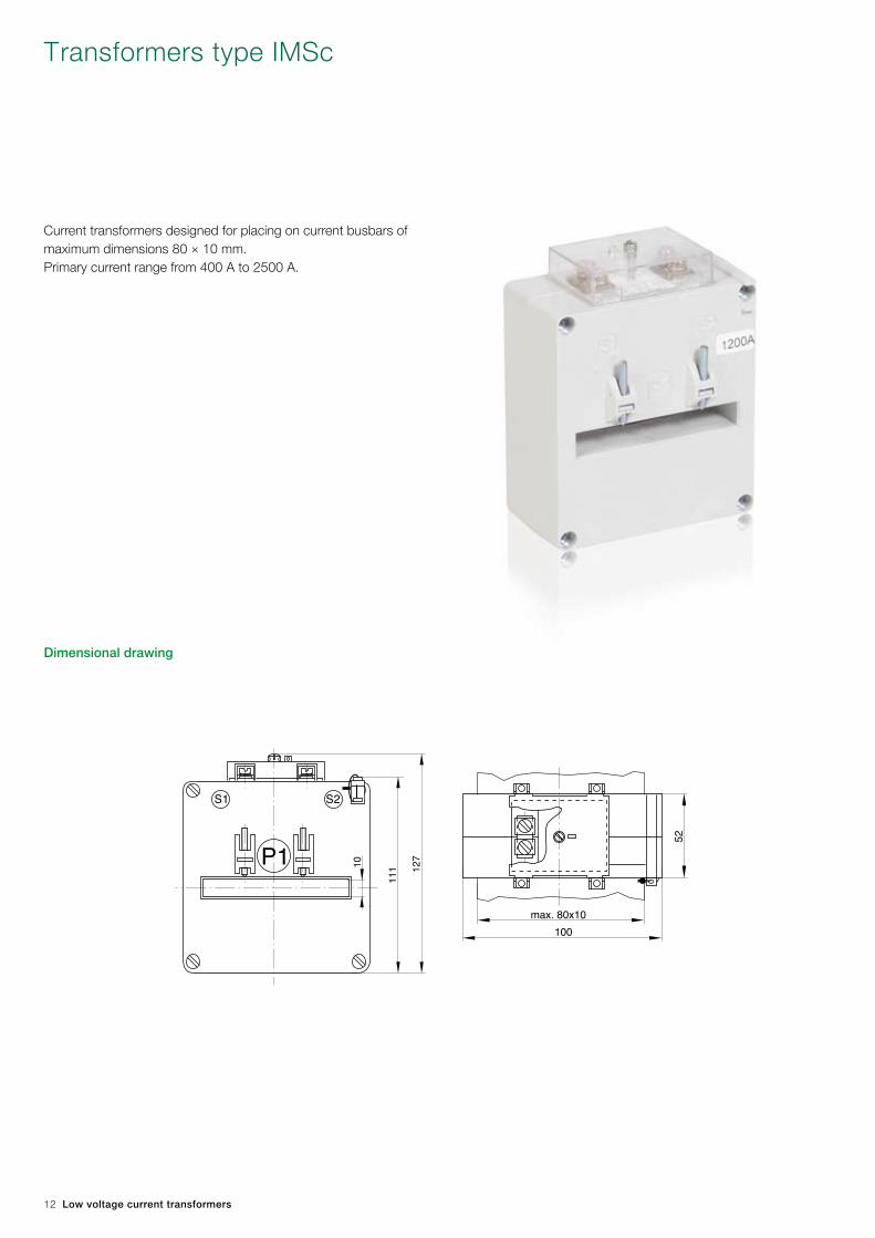
Transformers type IMSc
Dimensional drawing
Current transformers designed for placing on current busbars of maximum dimensions 80 × 10 mm.Primary current range from 400 A to 2500 A.

Low voltage current transformers 13
Type
Cla
ss Ipn Isn Security factor FS Rated operation current Maximum
permissible
voltage Um
Rated test
voltage Up
Weight
(approx.)Burden short-time
thermal Ith
peak
Idyn2.5 5 7.5 10 15 20 30
[A] [A] [VA] [VA] [VA] [VA] [VA] [VA] [VA] [A] [A] [kV] [kV] [kg]
IMSc
0.2S
1000
5
10
60xIpn 150xIpn
0.72 3 0.9
1200 10
1500 10
2000 10 10100 kA 250 kA
2500 10 10
0.5S
400
5
10
60xIpn 150xIpn
800 5; 10
1000 5; 10 5; 10 5; 10
1200 5; 10 5; 10 5; 10
1500 5; 10 5; 10 5; 10 5; 10
2000 10 10 10100 kA 250 kA
2500 10 10
0.2
400 5 5; 10
60xIpn 150xIpn
600
5 or 1
5; 10
750 5; 10
800 5; 10 5; 10
1000 5; 10 5; 10 5; 10 5; 10 5; 10
1200 10 10 5; 10 5; 10 5; 10
1500 10 10 10 10
1600 10 10 10 10
2000 10 10 10 10100 kA 250 kA
2500 5 10 10 5; 10 5; 10
0.5
4005
5; 10 5; 10 5; 10 5; 10
60xIpn 150xIpn
500 5; 10 5; 10 5; 10 5; 10
600
5 or 1
5; 10 5; 10 5; 10
750 5; 10 5; 10 5; 10 5; 10
800 5; 10 5; 10 5; 10 5; 10
1000 10 5; 10 5; 10 5; 10 5; 10 5; 10 5; 10
1200 5; 10 5; 10 5; 10 5; 10 5; 10 5; 10
1500 5; 10 5; 10 5; 10 5; 10 5; 10
1600 10 10 5; 10 5; 10 5; 10
2000 10 10 10 5; 10 5; 10100 kA 250 kA
2500 5 10 10 5; 10 5; 10
1; 3
400
5or 1
5; 10 5; 10 5; 10 5; 10
60xIpn 150xIpn
500 5; 10 5; 10 5; 10 5; 10 5;10 5;10
600 10 5; 10 5; 10 5; 10 5; 10 5;10
750 10 5; 10 5; 10 5; 10 5; 10 5;10
800 10 5; 10 5; 10 5; 10 5; 10 5; 10
1000 10 5; 10 5; 10 5; 10 5; 10 5; 10 5; 10
1200 10 5; 10 5; 10 5; 10 5; 10 5; 10 5; 10
1500 5; 10 5; 10 5; 10 5; 10 5; 10
1600 10 10 5; 10 5; 10 5; 10
2000 10 10 10 5; 10 5; 10100 kA 250 kA
2500 5 10 10 5; 10 5; 10
It is possible to order transformers of other parameters after prior arrangement with the manufacturer.

14 Low voltage current transformers
194
R43,25
1221025030
89
184
62
46
S1 S2
P1 4000A
194
R43,25
1221025030
89
184
62
46
S1 S2
P1 4000A
Transformers type IMSd
Dimensional drawing
Current transformers designed for placing on current busbars of maximum dimensions 120 x 30 mm or 100 x 50 mm. Also al-lows a cable of maximum 85 mm diameter to be pulled through. The transformer allows conversion of high currents and high powers. Can perform measurement class and protection class functions.

Low voltage current transformers 15
It is possible to order transformers of other parameters after prior arrangement with the manufacturer.There is a possibility of performing by special order transformers of primary current Ipn up to 6000 A and protection classes.
Type
Cla
ss Ipn Isn Security factor FS Rated operation current Maximum
permissible
voltage Um
Rated test
voltage Up
Weight
(approx.)Burden short-time
thermal Ith
peak
Idyn5 7.5 10 15 20 30 45 60 90 120
[A] [A] [VA] [VA] [VA] [VA] [VA] [VA] [VA] [VA] [VA] [VA] [kA] [kA] [kV] [kV] [kg]
IMSd
0.2S2500
510 62.5 156.5
0.72 3 1.8
3000 10 10 10 10 10 5; 10 75 187
0.5S
1000
5
10 37.5 100
1600 5; 10 40 105
2000 5; 10 5; 10 5; 10 5; 10 50 125
2500 10 5; 10 5; 10 5; 10 5; 10 62.5 156.5
3000 10 10 5; 10 5; 10 5; 10 5; 10 75 187
4000 10 10 10 5; 10 5; 10 5; 10100 250
5000 10 5; 10 5; 10 5; 10
0.2
10005
10 10
37.5 1001200 10 10 10
1500
5 or 1
10 5; 10 5; 10
1600 10 5; 10 5; 10 40 105
2000 10 5; 10 5; 10 5; 10 50 125
2500 10 10 5; 10 5; 10 5; 10 5; 10 62.5 156.5
3000 10 10 10 5; 10 5; 10 5; 10 5; 10 75 187
4000 10 10 10 5; 10 5; 10 5; 10 5; 10100 250
5000 5 10 5; 10 5; 10 5; 10
0.5
500
5 or 1
10 30 75
600 10 10 5; 10 36 90
750 10 10 5; 10
37.5 100
800 10 10 5; 10
1000 10 5; 10 5; 10 5; 10
1200 10 5; 10 5; 10 5; 10
1500 10 5; 10 5; 10 5; 10 5; 10
1600 10 5; 10 5; 10 5; 10 5; 10 5; 10 40 105
2000 10 5; 10 5; 10 5; 10 5; 10 5; 10 5; 10 5; 10 50 125
2500 10 10 5; 10 5; 10 5; 10 5; 10 5; 10 5; 10 62.5 156.5
3000 10 10 5; 10 5; 10 5; 10 5; 10 5; 10 5; 10 75 187
4000 10 10 10 5; 10 5; 10 5; 10 5; 10 5; 10100 250
5000 5 10 5; 10 5; 10 5; 10 5; 10
1; 3
500
5 or 1
10 30 75
600 5; 10 5; 10 5; 10 36 90
750 5; 10 5; 10 5; 10
37.5 100
800 5; 10 5; 10 5; 10
1000 5; 10 5; 10 5; 10 5; 10
1200 5; 10 5; 10 5; 10 5; 10
1500 5; 10 5; 10 5; 10 5; 10 5; 10 5; 10
1600 10 5; 10 5; 10 5; 10 5; 10 5; 10 40 105
2000 10 5; 10 5; 10 5; 10 5; 10 5; 10 5; 10 5; 10 50 125
2500 10 10 5; 10 5; 10 5; 10 5; 10 5; 10 5; 10 62.5 156.5
3000 10 10 5; 10 5; 10 5; 10 5; 10 5; 10 5; 10 75 187
4000 10 10 10 5; 10 5; 10 5; 10 5; 10 5; 10100 250
5000 5 10 5; 10 5; 10 5; 10 5; 10 5; 10

16 Low voltage current transformers
Transformers type IMPa
Dimensional drawing
9579
60
74
93
45 60 70
A
45
74
S1 S2
P1 20,2
S1 S2
9579
60
74
93
45 60 70
A
45
74
S1 S2
P1 20,2
S1 S2
9579
60
74
93
45 60 70
A
45
74
S1 S2
P1 20,2
S1 S2
9579
60
74
93
45 60 70
A
45
74
S1 S2
P1 20,2
S1 S2
Supporting version Seal wired version
Current transformers for cables of maximum 20 mm diameter. The transformer is equipped with a holder enabling it to be assembled on current busbars of maximum dimensions 20 x 10 mm.Primary current range from 100 A to 300 A.

Low voltage current transformers 17
It is possible to order transformers of other parameters after prior arrangement with the manufacturer.
Type
Cla
ss Ipn Isn Security factor FS Rated operation current Maximum
permissible
voltage Um
Rated test
voltage Up
Weight
(approx.)Burden short-time
thermal Ith
peak
Idyn2.5 5 7.5 10 15 20
[A] [A] [VA] [VA] [VA] [VA] [VA] [VA] [A] [A] [kV] [kV] [kg]
IMPa
0.5S
200
5
10 5; 10 10 10
60xIpn 150xIpn 0.72 3 0.8
250 5; 10 5; 10 10 5; 10
300 5; 10 5; 10 5; 10 5; 10
0.2
200 5 10 10 10
250
5
or
1
5; 10 5; 10 5; 10
300 5; 10 10 10
0.5
100 10
125 10 5; 10
150 5; 10 5; 10 5; 10
200 5; 10 5; 10 5; 10 5; 10 10
250 5; 10 5; 10 5; 10 5; 10 10
300 5; 10 5; 10 5; 10 5; 10 5; 10 5; 10
1; 3
100 10 10
125 10 5; 10
150 5; 10 5; 10 5; 10 5; 10
200 5; 10 5; 10 5; 10 5; 10 10
250 5; 10 5; 10 5; 10 5; 10 10 10
300 5; 10 5; 10 5; 10 5; 10 5; 10 5; 10

18 Low voltage current transformers
Transformers type IMPb
Dimensional drawing
Current transformers for cables of maximum 30 mm diameter. The transformer is equipped with a holder for assembly on current busbars of maximum dimensions 30 x 10 mm.Primary current range from 100 A to 600 A.
9579
60
74
93
45 60 70
A
45
74
S1 S2
P1 30,2
S1 S2
9579
60
74
93
45 60 70
A
45
74
S1 S2
P1 30,2
S1 S2
9579
60
74
93
45 60 70
A
45
74
S1 S2
P1 30,2
S1 S2
9579
60
74
93
45 60 70
A
45
74
S1 S2
P1 30,2
S1 S2
Supporting version Seal wired version

Low voltage current transformers 19
It is possible to order transformers of other parameters after prior arrangement with the manufacturer.
Type
Cla
ss Ipn Isn Security factor FS Rated operation current Maximum
permissible
voltage Um
Rated test
voltage Up
Weight
(approx.)Burden short-time
thermal Ith
peak
Idyn2.5 5 7.5 10 15 20
[A] [A] [VA] [VA] [VA] [VA] [VA] [VA] [A] [A] [kV] [kV] [kg]
IMPb
0.2S
250
5
5; 10
60xIpn 150xIpn 0.72 3 0.5
300 10
400 5; 10 5; 10 5; 10 5; 10
0.5S
200
5
5; 10
250 10 5; 10 10 5; 10
300 10 5; 10 5; 10 5; 10
400 5; 10 5; 10 5; 10 5; 10
500 5; 10 5; 10 5; 10
0.2
250 5 or 1
10 5; 10
300 10 5; 10 5; 10 5; 10
400 5; 10 5; 10 5; 10 5; 10
500 5 5; 10 5; 10 5; 10
0.5
150
5 or 1
10
200 10 5; 10 5; 10
250 10 5; 10 5; 10 5; 10
300 5; 10 5; 10 5; 10 5; 10 5; 10
400 5; 10 5; 10 5; 10 5; 10 5; 10 5; 10
500 5 5; 10 5; 10 5; 10 5; 10 5; 10 5; 10
1; 3
100
5 or 1
10
150 10 10
200 10 10 5; 10 10 10
250 10 5; 10 5; 10 5; 10 10
300 5; 10 5; 10 5; 10 5; 10 5; 10 5; 10
400 5; 10 5; 10 5; 10 5; 10 5; 10 5; 10
5005
5; 10 5; 10 5; 10 5; 10 5; 10 5; 10
600 10 10 5; 10 5; 10 5; 10

20 Low voltage current transformers
Transformers type ISWb
Dimensional drawing
Current transformers for a cable of maximum 48 mm diameter or a busbar of maximum 60 × 30 mm dimensions. Primary current range from 250 A to 1600 A.
122
50
6131
47
5644
100
S1 S21000 A
P1
max.
122
50
6131
47
5644
100
S1 S21000 A
P1
max.

Low voltage current transformers 21
Type
Cla
ss Ipn Isn Security factor FS Rated operational Maximum permissible voltage Um
Rated test voltage Up
Weight (approx.)Burden short-time
thermal Ith
peak Idyn2.5 5 7.5 10 15 20 30
[A] [A] [VA] [VA] [VA] [VA] [VA] [VA] [VA] [A] [A] [kV] [kV] [kg]
ISWb
0.2S 1200 5 5; 10
60xIpn 150xIpn 0.72 3 0.8
0.5S
600
5
5; 10 5; 10 5; 10
1000 5; 10 5; 10 5; 10
1200 10 5; 10 5; 10 5; 10
1500 10 5; 10 5; 10 5; 10 5; 10
0.2
500
5
5; 10
600 5; 10
1000 10 5; 10
1200 10 5; 10 5; 10
0.5
250
5 or 1
5; 10
300 5; 10 5; 10
400 5; 10 5; 10 5; 10
500 5; 10 5; 10 5; 10 5; 10
600 5; 10 5; 10 5; 10 5; 10 5; 10
750 5; 10 5; 10 5; 10 5; 10 5; 10
800 5; 10 5; 10 5; 10 5; 10 5; 10
1000 5; 10 5; 10 5; 10 5; 10 5; 10 5; 10 5; 10
1200 10 5; 10 5; 10 5; 10 5; 10 5; 10 5; 10
1500 5; 10 5; 10 5; 10 5; 10 5; 10 5; 10
1600 5; 10 5; 10 5; 10 5; 10 5; 10 5; 10
1; 3
250 5; 10 5; 10
300 5; 10 5; 10
400 5; 10 5; 10 5; 10 5; 10
500 5; 10 5; 10 5; 10 5; 10 5; 10
600 5; 10 5; 10 5; 10 5; 10 5; 10
750 5; 10 5; 10 5; 10 5; 10 5; 10
800 5; 10 5; 10 5; 10 5; 10 5; 10 5; 10
1000 5; 10 5; 10 5; 10 5; 10 5; 10 5; 10 5; 10
1200 10 5; 10 5; 10 5; 10 5; 10 5; 10 5; 10
1500 5; 10 5; 10 5; 10 5; 10 5; 10 5; 10
1600 5; 10 5; 10 5; 10 5; 10 5; 10 5; 10
It is possible to order transformers of other parameters after prior arrangement with the manufacturer.

22 Low voltage current transformers
Transformers type ISWb2
Dimensional drawing
104
54
76
32 123
52
104
55
62
47
48 62
Current transformers designed for mounting on current busbars of maximum dimensions 75 x 30 mm.Primary current range from 500 A to 1200 A.

Low voltage current transformers 23
It is possible to order transformers of other parameters after prior arrangement with the manufacturer.
Type
Cla
ss Ipn Isn Security factor FS Rated operation current Maximum
permissible
voltage Um
Rated test
voltage Up
Weight
(approx.)Burden short-time
thermal Ith
peak
Idyn2.5 5 7.5 10 15 20
[A] [A] [VA] [VA] [VA] [VA] [VA] [VA] [A] [A] [kV] [kV] [kg]
ISWb2
0.5S
600
5
10
60xIpn 150xIpn 0.72 3 0.7
750 10 10 5; 10
800 10 10 5; 10 5; 10
1000 10 10 5; 10 5; 10 5; 10
1200 10 10 5; 10 5; 10 5; 10 5; 10
0.2
750 5 or 1
10 10 5; 10
800 10 10 10
1000 10 10 5; 10 5; 10
1200 5 10 10 5; 10 5; 10 5; 10 5; 10
0.5
500
5 or 1
10 10
600 10 10 5; 10 5; 10
750 10 10 5; 10 5; 10
800 10 10 5; 10 5; 10 5; 10
1000 10 10 5; 10 5; 10 5; 10 5; 10
1200 5 10 10 5; 10 5; 10 5; 10 5; 10
1; 3
500
5 or 1
10 10 5; 10 5; 10
600 10 10 5; 10 5; 10
750 10 10 5; 10 5; 10
800 10 10 5; 10 5; 10 5; 10
1000 10 10 5; 10 5; 10 5; 10 5; 10
1200 5 10 10 5; 10 5; 10 5; 10 5; 10
24 Low voltage current transformers
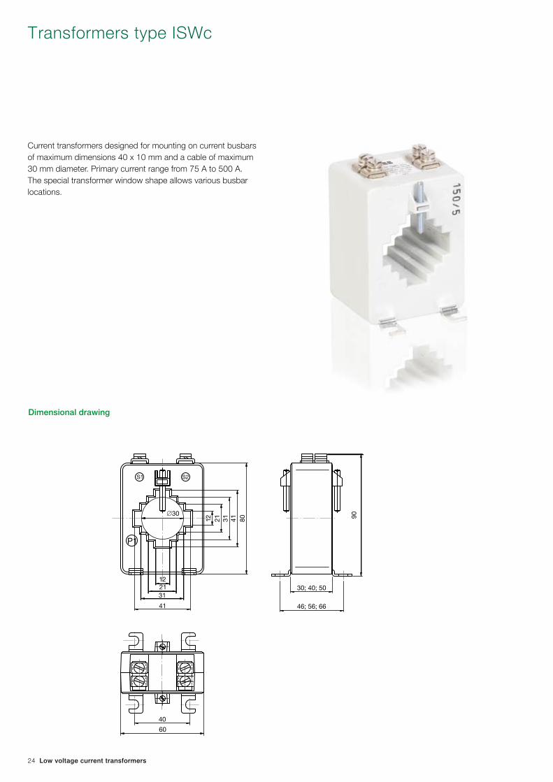
Transformers type ISWc
Dimensional drawing
46; 56; 66
30; 40; 50
90∅30
60
40
122131
41
12 21 31 41 80
P1
S2S1
Current transformers designed for mounting on current busbars of maximum dimensions 40 x 10 mm and a cable of maximum 30 mm diameter. Primary current range from 75 A to 500 A. The special transformer window shape allows various busbar locations.

Low voltage current transformers 25
It is possible to order transformers of other parameters after prior arrangement with the manufacturer.
Type
Cla
ss Ipn Isn Security factor FS Rated operation current Maximum
permissible
voltage Um
Rated test
voltage Up
Weight
(approx.)Burden short-time
thermal Ith
peak
Idyn1 2.5 5 7.5 10 15 20 25
[A] [A] [VA] [VA] [VA] [VA] [VA] [VA] [VA] [VA] [A] [A] [kV] [kV] [kg]
ISWc
0.5S
300
5
5; 10
60xIpn 150xIpn 0.72 3 0.5
400 5; 10 5; 10
500 5; 10 5; 10 5; 10
0.2
300
5 or 1
10
400 5; 10
500 5; 10 5; 10 5; 10
0.5
150 10
200 10
250 10 5; 10
300 10 5; 10 5; 10 5; 10
400 5; 10 5; 10 5; 10 5; 10 5; 10
500 5; 10 5; 10 5; 10 5; 10 5; 10 5; 10
1
150 5; 10 5; 10
200 10 5; 10 5; 10
250 10 5; 10 5; 10 5; 10
300 10 5; 10 5; 10 5; 10 5; 10
400 5; 10 5; 10 5; 10 5; 10 5; 10
500 5; 10 5; 10 5; 10 5; 10 5; 10 5; 10 5; 10
3
75 10 5; 10
100 10 5; 10
150 5; 10 5; 10 5; 10
200 10 5; 10 5; 10
250 10 5; 10 5; 10 5; 10
300 10 5; 10 5; 10 5; 10 5; 10
400 5; 10 5; 10 5; 10 5; 10 5; 10
500 5; 10 5; 10 5; 10 5; 10 5; 10 5; 10 5; 10

26 Low voltage current transformers
Transformers type ISWd1
Dimensional drawing
47 or 62
55 or 70
A
56 o
r 71
141
123
81603012
52
12
30
60
81
100
6.5 80
47 or 62
55 or 70
A
56 o
r 71
141
123
81603012
52
12
30
60
81
100
6.5 80
Current transformers designed for mounting on current busbars of maximum dimensions 80 x 10 mm or 60 x 30 mm and a cable of maximum 55 mm diameter. Primary current range from 250 A to 1000 A. The special transformer window shape allows various busbar locations.
For Ipn = 600 A dimension A = 40 mmFor Ipn ≠ 600 A dimension A = 55 mm

Low voltage current transformers 27
It is possible to order transformers of other parameters after prior arrangement with the manufacturer.
Type
Cla
ss Ipn Isn Security factor FS Rated operation current Maximum
permissible
voltage Um
Rated test
voltage Up
Weight
(approx.)Burden short-time
thermal Ith
peak
Idyn2.5 5 7.5 10 15 20
[A] [A] [VA] [VA] [VA] [VA] [VA] [VA] [A] [A] [kV] [kV] [kg]
ISWd1
0.5S
500
5
10
60xIpn 150xIpn 0.72 3 0.7
600 10 5; 10
750 10 5; 10 5; 10 5; 10 5; 10
800 10 5; 10 5; 10 5; 10 5; 10
1000 10 5; 10 5; 10 5; 10 5; 10 5; 10
0.2
6005
or 1
10
750 10 5; 10 5; 10
800 10 5; 10 5; 10
1000 10 5; 10 5; 10 5; 10
0.5
250
5 or 1
10
300 10
400 10 5; 10
500 10 5; 10 5; 10
600 10 5; 10 5; 10 5; 10
750 10 5; 10 5; 10 5; 10 5; 10
800 10 5; 10 5; 10 5; 10 5; 10
1000 10 5; 10 5; 10 5; 10 5; 10 5; 10
1; 3
250 10 10
300 10 5; 10
400 10 5; 10 5; 10 5; 10
500 10 5; 10 5; 10 5; 10
600 10 5; 10 5; 10 5; 10
750 10 5; 10 5; 10 5; 10
800 10 5; 10 5; 10 5; 10 5; 10
1000 10 5; 10 5; 10 5; 10 5; 10 5; 10

28 Low voltage current transformers
Transformers type ISWd2
Dimensional drawing
∅55
30 60 123
30
81
52
100
141
70
62
7155
806.5
∅55
30 60 123
30
81
52
100
141
70
62
7155
806.5
Current transformers designed for mounting on current busbars of maximum dimensions 80 x 30 mm (horizontal) or 60 x 30 mm (vertical) and a cable of maximum 55 mm diameter. Primary current range from 1000 A to 1600 A. The special transformer window shape allows various busbar locations.

Low voltage current transformers 29
It is possible to order transformers of other parameters after prior arrangement with the manufacturer.
Type
Cla
ss
Ipn Isn Security factor FS Rated operation current Maximum
permissible
voltage Um
Rated test
voltage Up
Weight
(approx.)Burden short-time
thermal Ith
peak
Idyn2.5 5 7.5 10 15
[A] [A] [VA] [VA] [VA] [VA] [VA] [A] [A] [kV] [kV] [kg]
ISWd2
0.5S
1000
5
10 5; 10
60xIpn 150xIpn 0.72 3 0.7
1200 10 5; 10 5; 10 5; 10
1500 10 5; 10 5; 10 5; 10
1600 10 5; 10 5; 10 5; 10 5; 10
0.2
1200 5
or 1
10 5; 10 5; 10
1500 10 5; 10 5; 10
1600 10 5; 10 5; 10
0.5
1000
5
or 1
10 5; 10 5; 10
1200 10 5; 10 5; 10 5; 10
1500 10 5; 10 5; 10 5; 10 5; 10
1600 10 5; 10 5; 10 5; 10 5; 10
1; 3
1000 10 5; 10 5; 10
1200 10 5; 10 5; 10 5; 10
1500 10 5; 10 5; 10 5; 10 5; 10
1600 10 5; 10 5; 10 5; 10 5; 10

30 Low voltage current transformers
Transformers type ISWe
Dimensional drawing
78 or 58
70 or 50
A
78or
58
123
170
122
50
35
70
140
80
164
For Ipn ≤ 2500 A dimension A = 42 mmFor Ipn > 2500 A dimension A = 62 mm
Current transformers designed for mounting on current busbars of maximum dimensions 120 x 30 mm. Primary current range from 400 A to 4000 A.

Low voltage current transformers 31
It is possible to order transformers of other parameters after prior arrangement with the manufacturer.There is a possibility of performing by special order transformers of primary current Ipn up to 6000 A.
Type
Cla
ss Ipn Isn Security factor FS Rated operation current Maximum
permissible
voltage Um
Rated test
voltage Up
Weight
(approx.)Burden short-time
thermal Ith
peak
Idyn2.5 5 7.5 10 15 20 30 45 60 75
[A] [A] [VA] [VA] [VA] [VA] [VA] [VA] [VA] [VA] [VA] [VA] [A] [A] [kV] [kV] [kg]
ISWe
0.2S
1500
5
1060xIpn 150xIpn
0.72 3 2
1600 10 10
2000 10 10 10 10
100 kA 250 kA2500 10 10 10 10 10 5; 10
3000 10 10 10 10 10 5; 10
4000 10 10 10 10 10 10 5; 10
0.5S
600
5
10 10
60xIpn 150xIpn
750 10 10 5; 10
800 10 10 5; 10 5; 10
1000 10 10 10 5; 10
1200 10 10 10 5; 10
1500 10 10 10 5; 10 5; 10 5; 10
1600 10 10 10 5; 10 5; 10 5; 10
2000 10 10 10 10 10
100 kA 250 kA2500 10 10 10 10 10 5; 10 5; 10
3000 10 10 10 10 10 5; 10 5; 10
4000 10 10 10 10 10 10 5; 10
0.2
600
5 or 1
10 10
60xIpn 150xIpn
750 10 10
800 10 10 5; 10
1000 10 10 10 5; 10
1200 10 10 10 5; 10
1500 10 10 10 5; 10 5; 10 5; 10
1600 10 10 10 5; 10 5; 10 5; 10
2000 10 10 10 10 5; 10
100 kA 250 kA2500 10 10 10 10 10 5; 10 5; 10
3000 10 10 10 10 10 5; 10 5; 10
4000 10 10 10 10 10 10 5; 10
0.5
400
5 or 1
10
60xIpn 150xIpn
500 10 10
600 10 10 5; 10
750 10 10 5; 10 5; 10
800 10 10 5; 10 5; 10 5; 10
1000 10 10 10 5; 10 5; 10
1200 10 10 10 5; 10 5; 10
1500 10 10 10 5; 10 5; 10 5; 10
1600 10 10 10 5; 10 5; 10 5; 10
2000 10 10 10 10 5; 10 5; 10
100 kA 250 kA2500 10 10 10 10 10 5; 10 5; 10
3000 10 10 10 10 10 5; 10 5; 10 5; 10
4000 10 10 10 10 10 10 5; 10 5; 10
1; 3
400
5 or 1
10 10 5; 10
60xIpn 150xIpn
500 10 10 5; 10 10
600 10 10 5; 10 5; 10 5; 10
750 10 10 5; 10 5; 10 5; 10
800 10 10 5; 10 5; 10 5; 10 5; 10
1000 10 10 10 5; 10 5; 10 5; 10
1200 10 10 10 5; 10 5; 10 5; 10 5; 10
1500 10 10 10 5; 10 5; 10 5; 10 5; 10
1600 10 10 10 5; 10 5; 10 5; 10 5; 10
2000 10 10 10 10 5; 10 5; 10 5; 10
100 kA 250 kA2500 10 10 10 10 10 5; 10 5; 10 5; 10
3000 10 10 10 10 10 5; 10 5; 10 5; 10 5; 10
4000 10 10 10 10 10 10 5; 10 5; 10 5; 10

32 Low voltage current transformers
Transformers type ISWf
Dimensional drawing
67 68
55
150 17
0
60
76
100
129
R 35
102.5
6.5
76
88
Current transformers designed for mounting on current busbars of maximum dimensions 100 x 55 mm and a cable of maximum 70 mm diameter. Primary current range from 500 A to 2500 A.

Low voltage current transformers 33
It is possible to order transformers of other parameters after prior arrangement with the manufacturer.There is a possibility of performing by special order transformers of primary current Ipn up to 3000 A.
Type
Cla
ss Ipn Isn Security factor FS Rated operation current Maximum
permissible
voltage Um
Rated test
voltage Up
Weight
(approx.)Burden short-time
thermal Ith
peak
Idyn2.5 5 7.5 10 15 20 30 45
[A] [A] [VA] [VA] [VA] [VA] [VA] [VA] [VA] [VA] [A] [A] [kV] [kV] [kg]
ISWf
0.5S
600
5
10
60xIpn 150xIpn
0.72 3 2
750 10
800 10 10 5; 10
1000 10 10 5; 10
1200 10 10 5; 10 5; 10
1500 10 10 10 5; 10 5; 10
1600 10 10 10 5; 10 5; 10
2000 10 10 10 5; 10 5; 10 5; 10 5; 10100 kA 250 kA
2500 10 10 10 10 5; 10 5; 10 5; 10
0.2
1200
5 or 1
10 10 10
60xIpn 150xIpn1500 10 10 10 5; 10 5; 10
1600 10 10 10 5; 10 5; 10
2000 10 10 10 5; 10 5; 10 5; 10100 kA 250 kA
2500 10 10 10 10 5; 10 5; 10
0.5
500
5 or 1
10 10 5; 10
60xIpn 150xIpn
600 10 10 5; 10 5; 10 5; 10
750 10 10 5; 10 5; 10 5; 10
800 10 10 5; 10 5; 10 5; 10
1000 10 10 5; 10 5; 10 5; 10
1200 10 10 5; 10 5; 10 5; 10 5; 10
1500 10 10 10 5; 10 5; 10 5; 10 5; 10
1600 10 10 10 5; 10 5; 10 5; 10 5; 10
2000 10 10 10 5; 10 5; 10 5; 10 5; 10 5; 10100 kA 250 kA
2500 10 10 10 10 5; 10 5; 10 5; 10
1; 3
500
5 or 1
10 10 5; 10 5; 10
60xIpn 150xIpn
600 10 10 5; 10 5; 10 5; 10
750 10 10 5; 10 5; 10 5; 10
800 10 10 5; 10 5; 10 5; 10
1000 10 10 5; 10 5; 10 5; 10 5; 10
1200 10 10 5; 10 5; 10 5; 10 5; 10
1500 10 10 10 5; 10 5; 10 5; 10 5; 10
1600 10 10 10 5; 10 5; 10 5; 10 5; 10
2000 10 10 10 5; 10 5; 10 5; 10 5; 10 5; 10100 kA 250 kA
2500 10 10 10 10 5; 10 5; 10 5; 10

34 Low voltage current transformers
Transformers type ISWg
Dimensional drawing
88
46
60
110
30
130
67
74
52
60
76
88
6.5
R 23
88
46
60
110
30
130
67
74
52
60
76
88
6.5
R 23
Current transformers designed for mounting on current busbars of maximum dimensions 60 x 30 mm and a cable of maximum 46 mm diameter. Primary current range from 300 A to 1500 A.

Low voltage current transformers 35
It is possible to order transformers of other parameters after prior arrangement with the manufacturer.
Type
Cla
ss Ipn Isn Security factor FS Rated operation current Maximum
permissible
voltage Um
Rated test
voltage Up
Weight
(approx.)Burden short-time
thermal Ith
peak
Idyn2.5 5 7.5 10 15 20 30
[A] [A] [VA] [VA] [VA] [VA] [VA] [VA] [VA] [A] [A] [kV] [kV] [kg]
ISWg
0.2S 1500 5 10 10 10 5; 10
60xIpn 150xIpn 0.72 3 2
0.5S
500
5
5; 10
600 10
750 10 5; 10 5; 10 5; 10
800 10 5; 10 5; 10 5; 10
1000 10 10 5; 10 5; 10 5; 10 5; 10
1200 10 10 5; 10 5; 10 5; 10 5; 10 5; 10
1500 10 10 10 5; 10 5; 10 5; 10 5; 10
0.2
7505
or 1
10 5; 10
800 10 5; 10
1000 10 10 5; 10 5; 10 5; 10
1200 10 10 5; 10 5; 10 5; 10
1500 5 10 10 5; 10 5; 10 5; 10 5; 10
0.5
300 5 10 10
400
5 or 1
5; 10
500 5; 10 5; 10 5; 10
600 10 5; 10 5; 10
750 10 5; 10 5; 10 5; 10
800 10 5; 10 5; 10 5; 10
1000 10 10 5; 10 5; 10 5; 10 5; 10 5; 10
1200 10 10 5; 10 5; 10 5; 10 5; 10 5; 10
1500 5 10 10 10 5; 10 5; 10 5; 10 5; 10
1; 3
300 5 10 10
400
5 or 1
5; 10 5; 10
500 5; 10 5; 10 5; 10
600 10 5; 10 5; 10 5; 10
750 10 5; 10 5; 10 5; 10
800 10 5; 10 5; 10 5; 10 5; 10
1000 10 10 5; 10 5; 10 5; 10 5; 10 5; 10
1200 10 10 5; 10 5; 10 5; 10 5; 10 5; 10
1500 5 10 10 10 5; 10 5; 10 5; 10 5; 10

36 Low voltage current transformers
Transformers type ISWh1
Dimensional drawing
47 or 67
54 or 74
40or
60
56or
76
68or
88
52
62
85
100813212
62
6.5
47 or 67
54 or 74
40or
60
56or
76
68or
88
52
62
85
100813212
62
6.5
47 or 67
54 or 74
40or
60
56or
76
68or
88
52
62
85
100813212
62
6.5
Current transformers designed for mounting on current busbars of maximum dimensions 60 x 10 mm or 50 x 30 mm. Primary current range from 200 A to 1000 A.

Low voltage current transformers 37
It is possible to order transformers of other parameters after prior arrangement with the manufacturer.
Type
Cla
ss Ipn Isn Security factor FS Rated operation current Maximum
permissible
voltage Um
Rated test
voltage Up
Weight
(approx.)Burden short-time
thermal Ith
peak
Idyn2.5 5 7.5 10 15 20 30
[A] [A] [VA] [VA] [VA] [VA] [VA] [VA] [VA] [A] [A] [kV] [kV] [kg]
ISWh1
0.5S
300
5
10
60xIpn 150xIpn 0.72 3 0.8
400 10 5; 10
500 10 5; 10 5; 10
600 10 10 5; 10 5; 10
750 10 10 5; 10 5; 10 5; 10
800 10 10 5; 10 5; 10 5; 10
1000 10 5; 10 5; 10 5; 10 5; 10 5; 10
0.2
500
5 or 1
10 5; 10
600 10 10
750 10 10
800 10 10
1000 10 5; 10 5; 10 5; 10 5; 10
0.5
200
5 or 1
10
250 10 5; 10
300 10 5; 10 5; 10
400 10 5; 10 5; 10 5; 10
500 10 5; 10 5; 10 5; 10
600 10 10 5; 10 5; 10 5; 10
750 10 10 5; 10 5; 10 5; 10
800 10 10 5; 10 5; 10 5; 10
1000 10 5; 10 5; 10 5; 10 5; 10 5; 10
1; 3
200
5 or 1
10 5; 10
250 10 5; 10
300 10 5; 10 5; 10 5; 10
400 10 5; 10 5; 10 5; 10
500 10 5; 10 5; 10 5; 10 5; 10
600 10 10 5; 10 5; 10 5; 10
750 10 10 5; 10 5; 10 5; 10 5; 10
800 10 10 5; 10 5; 10 5; 10 5; 10
1000 10 5; 10 5; 10 5; 10 5; 10 5; 10 5; 10

38 Low voltage current transformers
Transformers type ISWh2
Dimensional drawing
47 or 67
54 or 74
A =
40
or 6
0
.
65 o
r 76
68 o
r 88
47 or 67
54 or 74
A =
40
or 6
0
.
65 o
r 76
68 o
r 88
Current transformers designed for mounting on cable of maximum 46 mm diameter. Primary current range from 200 A to 1200 A.
For Ipn =< 800 A dimension A = 40 mmFor Ipn > 800 A dimension A = 40 mm or 60 mm
47 or 67
54 or 74
A =
40
or 6
0
.
65 o
r 76
68 o
r 88

Low voltage current transformers 39
It is possible to order transformers of other parameters after prior arrangement with the manufacturer.*dimension A = 60
Type
Cla
ss Ipn Isn Security factor FS Rated operation current Maximum
permissible
voltage Um
Rated test
voltage Up
Weight
(approx.)Burden short-time
thermal Ith
peak
Idyn2.5 5 7.5 10 15 20 30
[A] [A] [VA] [VA] [VA] [VA] [VA] [VA] [VA] [A] [A] [kV] [kV] [kg]
ISWh2
0.5S
300
5
5; 10
60xIpn 150xIpn 0.72 3 0.8
400 5; 10 5; 10
500 5; 10 5; 10 5; 10
600 5; 10 5; 10 5; 10 5; 10
750 5; 10 5; 10 5; 10 5; 10 5; 10
800 5; 10 5; 10 5; 10 5; 10 5; 10
1000 5; 10 5; 10 5; 10* 5; 10* 5; 10* 5; 10*
1200 5; 10 5; 10 5; 10* 5; 10* 5; 10* 5; 10*
0.2
500
5 or 1
5; 10 5; 10
600 5; 10 5; 10
750 5; 10 5; 10
800 5; 10 5; 10
1000 5; 10 5; 10 5; 10* 5; 10* 5; 10*
1200 5 5; 10 5; 10 5; 10* 5; 10* 5; 10*
0.5
200
5 or 1
5; 10
250 5; 10 5; 10
300 5; 10 5; 10 5; 10
400 5; 10 5; 10 5; 10 5; 10
500 5; 10 5; 10 5; 10 5; 10
600 5; 10 5; 10 5; 10 5; 10 5; 10
750 5; 10 5; 10 5; 10 5; 10 5; 10
800 5; 10 5; 10 5; 10 5; 10 5; 10
1000 5; 10 5; 10 5; 10* 5; 10* 5; 10* 5; 10*
1200 5 5; 10 5; 10 5; 10* 5; 10* 5; 10* 5; 10*
1; 3
200
5 or 1
5; 10 5; 10
250 5; 10 5; 10
300 5; 10 5; 10 5; 10 5; 10
400 5; 10 5; 10 5; 10 5; 10
500 5; 10 5; 10 5; 10 5; 10 5; 10
600 5; 10 5; 10 5; 10 5; 10 5; 10
750 5; 10 5; 10 5; 10 5; 10 5; 10 5; 10
800 5; 10 5; 10 5; 10 5; 10 5; 10 5; 10
1000 5; 10 5; 10 5; 10* 5; 10* 5; 10* 5; 10* 5; 10*
1200 5 5; 10 5; 10 5; 10* 5; 10* 5; 10* 5; 10* 5; 10*

40 Low voltage current transformers
Version with leaded cables LYc length approximately 20 cm
Version with secondary terminals
Transformers type IMR0
Dimensional drawingIMR0 – current transformers for a cable max 18 mm or a busbar max 20 x 5 mm.
44
34
20.5
∅18 65
A*
= 50
A*
= 50
44
56∅18
34
20.5
A =
30
A =
30
S1
P1
S2
5
S1
5
P1
S2
S1 S2
44
34
20.5
∅18 65
A*
= 50
A*
= 50
44
56∅18
34
20.5
A =
30
A =
30
S1
P1
S2
5
S1
5
P1
S2
S1 S2
44
34
20.5
∅18 65
A*
= 50
A*
= 50
44
56∅18
34
20.5
A =
30
A =
30
S1
P1
S2
5
S1
5
P1
S2
S1 S2
44
34
20.5
∅18 65
A*
= 50
A*
= 50
44
56∅18
34
20.5
A =
30
A =
30
S1
P1
S2
5
S1
5
P1
S2
S1 S2
Current transformers of small dimensions designed for mounting on a cable or busbar. Applied mainly for control measurements. Primary current range from 50 A to 200 A.

Low voltage current transformers 41
It is possible to order transformers of other parameters after prior arrangement with the manufacturer.*depth A=50 mm
Type
Cla
ss Ipn Isn Security factor FS Rated operation current Maximum
permissible
voltage Um
Rated test
voltage Up
Weight
(approx.)Burden short-time
thermal Ith
peak
Idyn1 2.5 4 5 7.5
[A] [A] [VA] [VA] [VA] [VA] [VA] [A] [A] [kV] [kV] [kg]
IMR0
0.5
100 5
or
1
5; 10*
60xIpn 150xIpn 0.72 3 0.4
150 5; 10 5; 10*
200 5; 10 5; 10*
1
50 1 5; 10
100
5
or
1
5; 10* 5; 10
150 5; 10 5; 10 5; 10* 5; 10*
200 5; 10 5; 10* 5; 10* 5; 10*
3
40 5; 10*
45 5; 10*
50 5; 10*
75 5; 10* 5; 10*
80 10
100 5; 10* 5; 10 5; 10*
150 5; 10 5; 10 5; 10* 5; 10*
200 5; 10 5; 10* 5; 10* 5; 10*
5
20
1
5; 10*
25 5; 10*
30 5; 10*
35 5; 10*
40
5
or
1
5; 10*
45 5; 10*
50 5; 10*
75 5; 10* 5; 10*
80 10
100 5; 10* 5; 10 5; 10*
150 5; 10 5; 10 5; 10* 5; 10*
200 5; 10 5; 10* 5; 10* 5; 10*

42 Low voltage current transformers
7263
.530
10.220.550
60
32
63.5
10.220.550
32
60
30
7263
.530
10.220.550
60
32
63.5
10.220.550
32
60
30
7263
.530
10.220.550
60
32
63.5
10.220.550
32
60
30
7263
.530
10.220.550
60
32
63.5
10.220.550
32
60
30
Transformers type IMR1a
Dimensional drawingIMR1a – current transformers for a cable max 18 mm or a busbar max 20 x 10 mm.
Version with secondary terminals
Version with leaded cables LYc length approximately 20 cm
Current transformers of small dimensions designed for mounting on a cable or busbar. Applied mainly for control measurements. Primary current range from 75 A to 400 A.

Low voltage current transformers 43
It is possible to order transformers of other parameters after prior arrangement with the manufacturer.
Type
Cla
ss Ipn Isn Security factor FS Rated operation current Maximum
permissible
voltage Um
Rated test
voltage Up
Weight
(approx.)Burden short-time
thermal Ith
peak
Idyn1 2.5 5 7.5 10 15
[A] [A] [VA] [VA] [VA] [VA] [VA] [VA] [A] [A] [kV] [kV] [kg]
IMR1a
0.5
150
5
or
1
10 5; 10
60xIpn 150xIpn 0.72 3 0.6
200 10 10 5; 10
250 10 5; 10
300 10 5; 10 5; 10
400 10 10 5; 10 5; 10
1
75 5; 10
100 5; 10 5; 10
150 10 5; 10 5; 10
200 10 5; 10 5; 10 5; 10
250 10 5; 10 5; 10
300 10 5; 10 5; 10 5; 10
400 10 10 5; 10 5; 10 5; 10
3; 5
50 5; 10
75 5; 10 5; 10
100 5; 10 5; 10
150 10 5; 10 5; 10
200 10 5; 10 5; 10 5; 10
250 10 5; 10 5; 10
300 10 5; 10 5; 10 5; 10
400 10 10 5; 10 5; 10 5; 10
5 40 5; 10

44 Low voltage current transformers
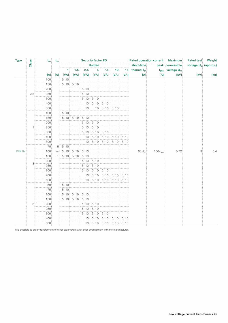
Transformers type IMR1b
Dimensional drawingIMR1b – current transformers for a cable max 23 mm or a busbar max 25 x 10 mm.
7263
.530
10.225.550
60
32
63.5
10.225.550
32
60
30
7263
.530
10.225.550
60
32
63.5
10.225.550
32
60
30
7263
.530
10.225.550
60
32
63.5
10.225.550
32
60
30
7263
.530
10.225.550
60
32
63.5
10.225.550
32
60
30
Version with secondary terminals
Version with leaded cables LYc length approximately 20 cm
Current transformers of small dimensions designed for mounting on a cable or busbar. Applied mainly for control measurements. Primary current range from 100 A to 500 A.
Low voltage current transformers 45
It is possible to order transformers of other parameters after prior arrangement with the manufacturer.
Type
Cla
ss Ipn Isn Security factor FS Rated operation current Maximum
permissible
voltage Um
Rated test
voltage Up
Weight
(approx.)Burden short-time
thermal Ith
peak
Idyn1 1.5 2.5 5 7.5 10 15
[A] [A] [VA] [VA] [VA] [VA] [VA] [VA] [VA] [A] [A] [kV] [kV] [kg]
IMR1b
0.5
100
5
or
1
5; 10
60xIpn 150xIpn 0.72 3 0.4
150 5; 10 5; 10
200 5; 10
250 5; 10
300 5; 10 5; 10
400 10 5; 10 5; 10
500 10 10 5; 10 5; 10
1
100 5; 10
150 5; 10 5; 10 5; 10
200 5; 10 5; 10
250 5; 10 5; 10
300 5; 10 5; 10 5; 10
400 10 5; 10 5; 10 5; 10 5; 10
500 10 5; 10 5; 10 5; 10 5; 10
3
75 5; 10
100 5; 10 5; 10 5; 10
150 5; 10 5; 10 5; 10
200 5; 10 5; 10
250 5; 10 5; 10
300 5; 10 5; 10 5; 10
400 10 5; 10 5; 10 5; 10 5; 10
500 10 5; 10 5; 10 5; 10 5; 10
5
50 5; 10
75 5; 10
100 5; 10 5; 10 5; 10
150 5; 10 5; 10 5; 10
200 5; 10 5; 10
250 5; 10 5; 10
300 5; 10 5; 10 5; 10
400 10 5; 10 5; 10 5; 10 5; 10
500 10 5; 10 5; 10 5; 10 5; 10

46 Low voltage current transformers
Transformers type IMR2
Dimensional drawingIMR2 – current transformers for a cable max 30 mm or a busbar max 40 x 10 mm.
Version with leaded cables LYc length approximately 20 cm
Version with secondary terminals
4498
38
10.2
20.230.540.5
54
75
58
P1
S1 S2
600A
P1
S1 S2
600A
S1 S2
80
Maks. średnica przewodu ∅ 30
4498
38
10.2
20.2
30.5
40.5
54
75
58
P1
S1 S2
600A
P1
S1 S2
600A
S1 S2
80
Max. diameter of cable Ø 30
Current transformers of small dimensions designed for mounting on a cable or busbar. Applied mainly for control measurements. Primary current range from 150 A to 800 A.

Low voltage current transformers 47
It is possible to order transformers of other parameters after prior arrangement with the manufacturer.
Type
Cla
ss Ipn Isn Security factor FS Rated operation current Maximum
permissible
voltage Um
Rated test
voltage Up
Weight
(approx.)Burden short-time
thermal Ith
peak
Idyn2.5 5 7.5 10 15 20
[A] [A] [VA] [VA] [VA] [VA] [VA] [VA] [A] [A] [kV] [kV] [kg]
IMR2
0.5S
400
5
10
60xIpn 150xIpn 0.72 3 0.6
500 5; 10 5; 10
600 10 10
0.2
400
5
10 5; 10
500 10 5; 10 5; 10
600 10 5; 10 5; 10
0.5
250
5
or
1
10 5; 10
300 10 5; 10 5; 10 5; 10
400 10 5; 10 5; 10 5; 10 5; 10
500 5; 10 5; 10 5; 10 5; 10 5; 10
600 10 5; 10 5; 10 5; 10 5; 10
630 5; 10 5; 10 5; 10 5; 10 5; 10
650 5; 10 5; 10 5; 10 5; 10 5; 10
800 5 5; 10 5; 10 5; 10 5; 10 5; 10
1; 3
150
5
or
1
10
200 10 5; 10
250 10 5; 10 5; 10 5; 10
300 10 5; 10 5; 10 5; 10
400 10 5; 10 5; 10 5; 10 5; 10
500 5; 10 5; 10 5; 10 5; 10 5; 10 5; 10
600 10 5; 10 5; 10 5; 10 5; 10 5; 10
630 5; 10 5; 10 5; 10 5; 10 5; 10
650 5; 10 5; 10 5; 10 5; 10 5; 10
800 5 5; 10 5; 10 5; 10 5; 10 5; 10

48 Low voltage current transformers
Transformers type INSOA
Dimensional drawing
72 30.2
47 64
70
56
40
8 6
S1 S2
INSO A
P1
72 30.2
47 64
70
56
40
8 6
S1 S2
INSO A
P1
Current transformers for special applications. Their special ad-vantage is fast saturation – FS2. Designed for mounting on leads of maximum 30 mm diameter. The transformer is equipped with holders allowing assembly of the transformer on current busbars of maximum dimensions 30 × 10 mm. Primary current range from 100 A to 400 A.

Low voltage current transformers 49
It is possible to order transformers of other parameters after prior arrangement with the manufacturer.
Type
Cla
ss Ipn Isn Security factor FS Rated operation current Maximum
permissible
voltage Um
Rated test
voltage Up
Weight
(approx.)Burden short-time
thermal Ith
peak
Idyn2.5 4 5 7.5 10
[A] [A] [VA] [VA] [VA] [VA] [VA] [A] [A] [kV] [kV] [kg]
INSOA 3; 5
100
5or 1
2
60xIpn 150xIpn 0.72 3 0.4
150 5; 10 2 2
200 2 2 2
250 2 2 2
300 2 2 2
400 10 5; 10 2 2 2

50 Low voltage current transformers
Accessories
Support for mounting the transformer on a TS35 mounting busbarThe mounting support allows mounting of some types of transformers on the TS35 mounting busbar (details in the transformer selection, table on page 52).
Voltage terminalTransformers (excluding IMSd) can be equipped with a voltage terminal. It is an element not connected inside the transformer. It is used to connect the voltage circuit from the busbar to the terminal and then to the measurement system.In transformers equipped with a cover there is the option of sealing this connection under the cover together with current circuit connections.The voltage terminal comes as part of a set with the busbar, to which it is connected by a permanently mounted lead.
Busbar mounting assemblyBolt with openings for sealing, with a holder for 30 mm or 60 mm busbars.
Standard bolt with holder for 30 mm or 60 mm busbar
Copper sleeveSleeve dimension Ø 20/Ø 13 length 46 mm. Other dimensions available to special order.
Sketch drawing of the mounting base

Low voltage current transformers 51
BusbarsCopper nickel plated busbars with a set of assembly bolts.
Standard busbars
Busbar dimension [mm] Number of bolts Bolt dimension
20x5x150 2 M10
20x10x150 2 M10
30x5x150 2 M12
30x10x150 2 M12
40x5x150 2 M12
40x10x150 2 M12
60x5x150 2 M12
60x10x150 2 M12
80x8x230 4 M12
80x10x230 4 M12
It is possible to order busbars of other dimensions after prior arrangement with the manufacturer.

52 Low voltage current transformers
Transformer selection table
Type IMSa IMSb IMSc IMSd ISWb ISWb2 ISWc ISWd1 ISWd2 ISWe
Class 0.2S 0.5S 0.2 0.5 1; 3 0.2S 0.5S 0.2 0.5 1; 3 0.2S 0.5S 0.2 0.5 1; 3 0.2S 0.5S 0.2 0.5 1; 3 0.2S 0.5S 0.2 0.5 1; 3 0.2 0.5S 0.5 1; 3 0.2 0.5S 0.5 1 3 0.2 0.5S 0.5 1; 3 0.2 0.5S 0.5 1; 3 0.2S 0.2 0.5S 0.5 1; 3
Prim
ary
curr
ent
1
2
3
5
10
15
20
25
30
40
50
60
75 2.5
100 1 2.5
125
150 2.5 5 1 2.5 5
200 5 7.5 1 5 5
250 5 2.5 5 10 2.5 5 2.5 7.5 7.5 2.5 5
300 5 5 10 15 5 5 1 2.5 7.5 10 10 2.5 5
400 7.5 7.5 15 15 5 10 10 2.5 2.5 10 10 7.5 10 2.5 5 15 15 15 5 10 2.5 7.5
500 5 7.5 10 15 20 5 5 10 15 10 20 5 5 5 10 15 5 10 7.5 7.5 20 20 25 2.5 7.5 10 5 10
600 5 15 5 15 20 5 10 10 15 20 5 10 20 10 10 10 5 15 15 2.5 10 10 2.5 5 10 10 5 5 7.5 15
750 5 10 20 20 5 15 20 10 10 15 15 5 7.5 10 10 7.5 15 15 10 5 7.5 10 15
800 5 5 10 20 20 5 7.5 15 20 10 10 15 20 7.5 10 15 15 7.5 15 15 15 7.5 10 15 20
1000 7.5 15 10 20 20 5 10 20 30 30 10 10 15 15 10 7.5 30 30 10 15 20 20 10 20 20 20 5 7.5 7.5 10 10 15 20
1200 5 10 20 30 30 10 15 15 7.5 15 10 30 30 20 20 20 20 7.5 10 10 10 10 10 15 30
1500 5 15 15 20 20 10 20 30 20 30 30 7.5 10 15 15 5 20 20 20 30
1600 15 20 20 10 10 30 30 30 30 7.5 15 15 15 7.5 20 20 20 30
2000 7.5 10 15 20 20 30 15 60 60 15 20 20 30 45
2500 10 10 20 20 20 7.5 30 30 60 60 30 45 45 45 60
3000 30 30 45 60 60 30 45 45 60 75
4000 60 60 90 90 45 45 45 60 75
5000 60 60 90 120
dim
en-
sio
ns
[mm
] width 60 80 100 184 100 104 60 100 100 170
depth 50 44 52 46 44 48 30; 40; 50 40; 55 55 42; 62
height 84 98 127 194 122 123 90 141 141 164
win
-d
ow
[m
m] busbar 40x10 60x10 80x10 120x30; 100x50 60x30 60x30 40x10 80x10 80x30 120x30
cable Ø – – – 86 48 – 30 55 55 –
primary current [A] 150-600 400-1000 400-2500 500-5000 250-1600 500-1200 75-500 250-1000 1000-1600 400-4000
mo
un
ting slides • • • • S S S S S S
assembly support • • • • • • • • • •on a current circuit U U Sd Sd Sd Sd Sd Sd Sd Sd
insulation class* A A E E E E E E E E
S – standard; • – available as additional equipment; • – not available; U –holder; Sd – set boltsProvided data refer to the secondary current value of 5A and FS10.Transformer maximum loading values in [VA] have been given in the table, at a given value of the primary current in [A] in a given class.More details and possibility of FS5 design have been given inside the catalogue.*Insulation class B available by special order.After arrangement with the manufacturer there is a possibility of transformer design of other: accuracy class, ratio, power or with an extended current range (ext. 150%; 200%).

Low voltage current transformers 53
Type IMSa IMSb IMSc IMSd ISWb ISWb2 ISWc ISWd1 ISWd2 ISWe
Class 0.2S 0.5S 0.2 0.5 1; 3 0.2S 0.5S 0.2 0.5 1; 3 0.2S 0.5S 0.2 0.5 1; 3 0.2S 0.5S 0.2 0.5 1; 3 0.2S 0.5S 0.2 0.5 1; 3 0.2 0.5S 0.5 1; 3 0.2 0.5S 0.5 1 3 0.2 0.5S 0.5 1; 3 0.2 0.5S 0.5 1; 3 0.2S 0.2 0.5S 0.5 1; 3
Prim
ary
curr
ent
1
2
3
5
10
15
20
25
30
40
50
60
75 2.5
100 1 2.5
125
150 2.5 5 1 2.5 5
200 5 7.5 1 5 5
250 5 2.5 5 10 2.5 5 2.5 7.5 7.5 2.5 5
300 5 5 10 15 5 5 1 2.5 7.5 10 10 2.5 5
400 7.5 7.5 15 15 5 10 10 2.5 2.5 10 10 7.5 10 2.5 5 15 15 15 5 10 2.5 7.5
500 5 7.5 10 15 20 5 5 10 15 10 20 5 5 5 10 15 5 10 7.5 7.5 20 20 25 2.5 7.5 10 5 10
600 5 15 5 15 20 5 10 10 15 20 5 10 20 10 10 10 5 15 15 2.5 10 10 2.5 5 10 10 5 5 7.5 15
750 5 10 20 20 5 15 20 10 10 15 15 5 7.5 10 10 7.5 15 15 10 5 7.5 10 15
800 5 5 10 20 20 5 7.5 15 20 10 10 15 20 7.5 10 15 15 7.5 15 15 15 7.5 10 15 20
1000 7.5 15 10 20 20 5 10 20 30 30 10 10 15 15 10 7.5 30 30 10 15 20 20 10 20 20 20 5 7.5 7.5 10 10 15 20
1200 5 10 20 30 30 10 15 15 7.5 15 10 30 30 20 20 20 20 7.5 10 10 10 10 10 15 30
1500 5 15 15 20 20 10 20 30 20 30 30 7.5 10 15 15 5 20 20 20 30
1600 15 20 20 10 10 30 30 30 30 7.5 15 15 15 7.5 20 20 20 30
2000 7.5 10 15 20 20 30 15 60 60 15 20 20 30 45
2500 10 10 20 20 20 7.5 30 30 60 60 30 45 45 45 60
3000 30 30 45 60 60 30 45 45 60 75
4000 60 60 90 90 45 45 45 60 75
5000 60 60 90 120
dim
en-
sio
ns
[mm
] width 60 80 100 184 100 104 60 100 100 170
depth 50 44 52 46 44 48 30; 40; 50 40; 55 55 42; 62
height 84 98 127 194 122 123 90 141 141 164
win
-d
ow
[m
m] busbar 40x10 60x10 80x10 120x30; 100x50 60x30 60x30 40x10 80x10 80x30 120x30
cable Ø – – – 86 48 – 30 55 55 –
primary current [A] 150-600 400-1000 400-2500 500-5000 250-1600 500-1200 75-500 250-1000 1000-1600 400-4000
mo
un
ting slides • • • • S S S S S S
assembly support • • • • • • • • • •on a current circuit U U Sd Sd Sd Sd Sd Sd Sd Sd
insulation class* A A E E E E E E E E

54 Low voltage current transformers
Transformer selection table
Type ISWf ISWg ISWh1 ISWh2 IMPa IMPb IMR0 IMR1a IMR1b IMR2 INSOA IMW
Class 0.5S 0.2 0.5 1; 3 0.2S 0.5S 0.2 0.5 1; 3 0.5S 0.2 0.5 1; 3 0.5S 0.2 0.5 1; 3 0.5S 0.2 0.5 1; 3 0.2S 0.5S 0.2 0.5 1; 3 0.5 1 3; 5 0.5 1 3; 5 0.5 1 3 5 0.5S 0.2 0.5 1; 3 3; 5 0.2S 0.5S 0.2 0.5 1; 3
Prim
ary
curr
ent
1 5 15 30
2 5 15 20
3 5 15 20
5 5 5 5 15 20
10 5 15 20
15 5 15 20
20 10 5 15 20
25 5 15 20
30 10 5 15 20
40 1 5 15 20
50 1 1 1 10 5 15 20
60 5 15 20
75 2.5 1 2.5 1 1 5 10 7.5 15 20
100 2.5 5 1 2.5 1 2.5 4 2.5 2.5 1 1 2.5 2.5 4 5 10 10 15 20
125 5 5 5 7.5 15 20
150 7.5 10 2.5 5 2.5 5 5 2.5 5 5 1.5 2.5 2.5 2.5 2.5 7.5 5 10 7.5 15 20
200 2.5 5 2.5 5 10 5 15 15 5 7.5 15 4 7.5 7.5 5 7.5 7.5 2.5 5 5 5 5 10 5 7.5 15 20
250 5 5 5 5 10 7.5 15 20 5 10 5 10 15 5 7.5 7.5 2.5 5 5 5 5 10 10 5 10 7.5 15 20
300 5 5 2.5 7.5 10 2.5 7.5 10 10 7.5 20 20 5 10 10 15 20 7.5 10 10 5 7.5 7.5 7.5 10 10 10 5 10 7.5 20 20
400 2.5 5 5 10 10 5 10 10 10 10 10 20 20 10 15 15 7.5 15 15 15 5 5 15 15 10
500 10 15 2.5 7.5 7.5 7.5 5 10 15 7.5 5 10 15 10 7.5 20 20 10 15 15 15 5 10 15 20
600 15 15 2.5 7.5 10 10 5 15 15 10 5 15 15 20 5 15 15 20
750 2.5 15 15 10 5 10 10 15 5 15 20 15 5 15 20
800 7.5 15 15 10 5 10 15 15 5 15 20 15 5 15 20 20 20
1000 7.5 15 20 20 15 30 30 20 15 20 30 20 15 20 30
1200 10 20 20 30 15 30 30 20 15 20 30
1500 15 15 30 30 10 30 20 30 30
1600 15 15 30 30
2000 30 20 45 45
2500 30 20 30 30
3000
4000
5000
dim
en-
sio
ns
[mm
] width 129 88 85 85 74 74 44 60 60 75 64 77.5
depth 60 60 40; 60 40; 60 45 45 30; 50 32 32 44 40 66
height 170 130 100 100 95 95 65 72 72 98 82 97
win
-d
ow
[m
m] busbar 100x55 60x30 60x10; 50x30 – 20x10 30x10 20x5 20x10 25x10 40x10 30x10 own busbar 20x5
cable Ø 70 46 – 45 20 30 18 18 23 30 30 –
primary current [A] 500-2500 300-1500 200-1000 200-1200 100-300 100-600 50-200 75-400 100-500 150-800 100-400 1-300
mo
un
ting slides S S S S S S S S S S S S
assembly support • • • • • • • • • • • •on a current circuit Sd Sd Sd Sd U U • • • Sd U •
insulation class* E E E E A A E E E E A E
S – standard; • – available as additional equipment; • – not available; U –holder; Sd – set boltsProvided data refer to the secondary current value of 5A and FS10.Transformer maximum loading values in [VA] have been given in the table, at a given value of the primary current in [A] in a given class.More details and possibility of FS5 design have been given inside the catalogue.*Insulation class B available by special order.After arrangement with the manufacturer there is a possibility of transformer design of other: accuracy class, ratio, power or with an extended current range (ext. 150%; 200%).

Low voltage current transformers 55
Type ISWf ISWg ISWh1 ISWh2 IMPa IMPb IMR0 IMR1a IMR1b IMR2 INSOA IMW
Class 0.5S 0.2 0.5 1; 3 0.2S 0.5S 0.2 0.5 1; 3 0.5S 0.2 0.5 1; 3 0.5S 0.2 0.5 1; 3 0.5S 0.2 0.5 1; 3 0.2S 0.5S 0.2 0.5 1; 3 0.5 1 3; 5 0.5 1 3; 5 0.5 1 3 5 0.5S 0.2 0.5 1; 3 3; 5 0.2S 0.5S 0.2 0.5 1; 3
Prim
ary
curr
ent
1 5 15 30
2 5 15 20
3 5 15 20
5 5 5 5 15 20
10 5 15 20
15 5 15 20
20 10 5 15 20
25 5 15 20
30 10 5 15 20
40 1 5 15 20
50 1 1 1 10 5 15 20
60 5 15 20
75 2.5 1 2.5 1 1 5 10 7.5 15 20
100 2.5 5 1 2.5 1 2.5 4 2.5 2.5 1 1 2.5 2.5 4 5 10 10 15 20
125 5 5 5 7.5 15 20
150 7.5 10 2.5 5 2.5 5 5 2.5 5 5 1.5 2.5 2.5 2.5 2.5 7.5 5 10 7.5 15 20
200 2.5 5 2.5 5 10 5 15 15 5 7.5 15 4 7.5 7.5 5 7.5 7.5 2.5 5 5 5 5 10 5 7.5 15 20
250 5 5 5 5 10 7.5 15 20 5 10 5 10 15 5 7.5 7.5 2.5 5 5 5 5 10 10 5 10 7.5 15 20
300 5 5 2.5 7.5 10 2.5 7.5 10 10 7.5 20 20 5 10 10 15 20 7.5 10 10 5 7.5 7.5 7.5 10 10 10 5 10 7.5 20 20
400 2.5 5 5 10 10 5 10 10 10 10 10 20 20 10 15 15 7.5 15 15 15 5 5 15 15 10
500 10 15 2.5 7.5 7.5 7.5 5 10 15 7.5 5 10 15 10 7.5 20 20 10 15 15 15 5 10 15 20
600 15 15 2.5 7.5 10 10 5 15 15 10 5 15 15 20 5 15 15 20
750 2.5 15 15 10 5 10 10 15 5 15 20 15 5 15 20
800 7.5 15 15 10 5 10 15 15 5 15 20 15 5 15 20 20 20
1000 7.5 15 20 20 15 30 30 20 15 20 30 20 15 20 30
1200 10 20 20 30 15 30 30 20 15 20 30
1500 15 15 30 30 10 30 20 30 30
1600 15 15 30 30
2000 30 20 45 45
2500 30 20 30 30
3000
4000
5000
dim
en-
sio
ns
[mm
] width 129 88 85 85 74 74 44 60 60 75 64 77.5
depth 60 60 40; 60 40; 60 45 45 30; 50 32 32 44 40 66
height 170 130 100 100 95 95 65 72 72 98 82 97
win
-d
ow
[m
m] busbar 100x55 60x30 60x10; 50x30 – 20x10 30x10 20x5 20x10 25x10 40x10 30x10 own busbar 20x5
cable Ø 70 46 – 45 20 30 18 18 23 30 30 –
primary current [A] 500-2500 300-1500 200-1000 200-1200 100-300 100-600 50-200 75-400 100-500 150-800 100-400 1-300
mo
un
ting slides S S S S S S S S S S S S
assembly support • • • • • • • • • • • •on a current circuit Sd Sd Sd Sd U U • • • Sd U •
insulation class* E E E E A A E E E E A E
56 Low voltage current transformers
Certificates
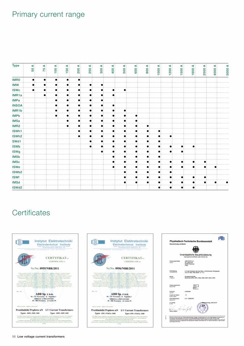
Primary current range
Type
50
A
75
A
10
0 A
15
0 A
20
0 A
25
0 A
30
0 A
40
0 A
50
0 A
60
0 A
80
0 A
10
00
A
12
00
A
15
00
A
16
00
A
25
00
A
40
00
A
50
00
A
IMR0 • • • • •IMW • • • • • • •ISWc • • • • • • • • •IMR1a • • • • • • •IMPa • • • • •INSOA • • • • • •IMR1b • • • • • • •IMPb • • • • • • • •IMSa • • • • • • •IMR2 • • • • • • • •ISWh1 • • • • • • • •ISWh2 • • • • • • • • • SWd1 • • • • • • •ISWb • • • • • • • • • •ISWg • • • • • • • •IMSb • • • • •IMSc • • • • • • • • •ISWe • • • • • • • • • •ISWb2 • • • • •ISWf • • • • • • • •IMSd • • • • • • • • • •ISWd2 • • • •


34
05
PL1
15
-W3
-en.
Ed
ition
11
.20
11
Contact us
ABB Sp. z o.o. Branch in Przasnysz59 Leszno Str.06-300 Przasnysz, PolandPhone: +48 29 75 33 377, +48 29 75 33 233 Fax: +48 29 75 33 327
www.abb.pl
We reserve the right to make technical changes or
modify the contents of this document without prior
notice. With regard to purchase orders, the agreed
particulars shall prevail.
ABB does not accept any responsi bility whatsoever
for potential errors or possible lack of information in this
document.
We reserve all rights in this document and in the
subject matter and illustrations contained therein.
Any reproduction – in whole or in parts – is forbidden
without ABB’s prior written consent.
© Copyright 2011 ABB
All rights reserved