low voltage switchgear and controlgear – functional safety ... · guidance how to use low voltage...
TRANSCRIPT
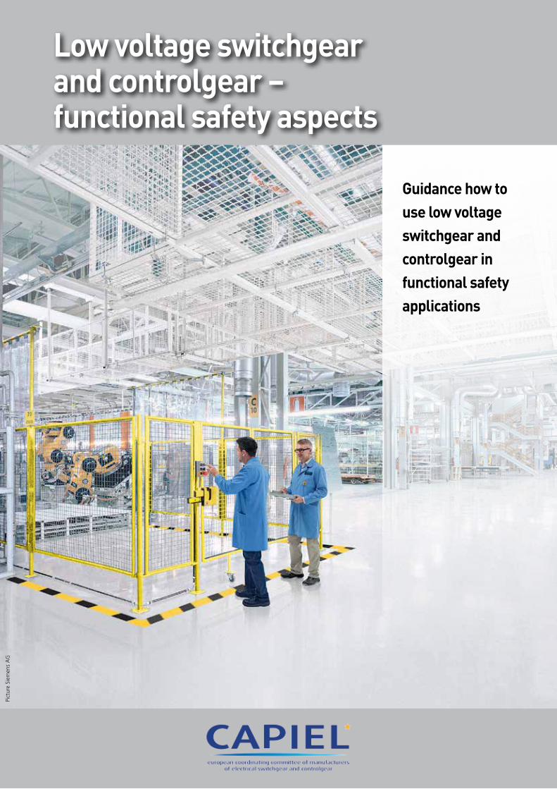
Guidance how to use low voltage switchgear and controlgear in functional safety applications
Low voltage switchgear and controlgear – functional safety aspects
Pict
ure
Siem
ens
AG

Philippe SauerCAPIEL President
Karlheinz KaulCAPIEL Vice-President
In the recent years machinery has become more and more complex. Based
on the European Machinery Directive the requirements for safety have also
increased. Therefore the European Union is very influential with regard to
functional safety in machine systems.
This has a major effect on CAPIEL products as well. Some CAPIEL products
may not meet the definition for a “safety component”, but nevertheless they
can have features or functions which allows a machine builder to use them
as a part of a system intended for safety applications.
It is one of our most important duties, as CAPIEL, to work with regulators in
order to ensure that features or functions are consistent with our common
safety objectives. It is our responsibility to make sure that these are clearly
defined, understandable and correctly interpreted by designers, installers and
other users of electrical products, systems and solutions.
This brochure provides information concerning the application of
current standards and the European Machinery Directive relevant to the
implementation of low voltage switchgear and controlgear in functional
safety applications.
We hope that you will find it of interest.
Yours sincerely
Philippe Sauer & Karlheinz Kaul
A message from the CAPIEL Presidents
CAPIEL is the European Coordinating Committee of Manufacturers of Electrical Switchgear and Controlgear
CAPIEL notably provides various start, control & safety solutions for machines.
CAPIEL plays an active role in driving emerging technologies, especially regarding innovations
in the areas of environmental preservation and sustainability, but also in health and safety.
MOTORSenSOR LOgic AcTUATOR
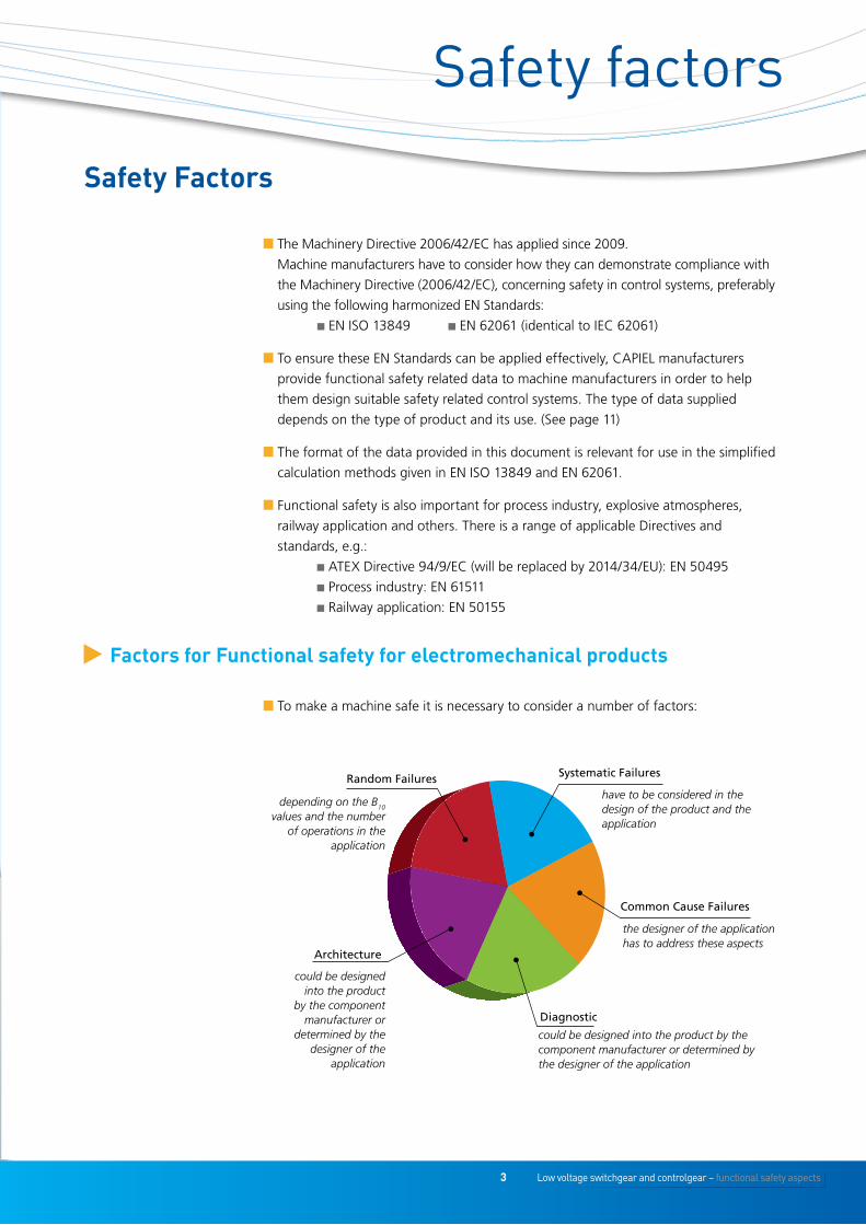
have to be considered in the design of the product and the application
the designer of the application has to address these aspects
could be designed into the product by the component manufacturer or determined by the designer of the application
could be designed into the product
by the component manufacturer or
determined by the designer of the
application
depending on the B10 values and the number
of operations in the application
t Factors for Functional safety for electromechanical products
Systematic Failures
Common Cause Failures
Diagnostic
Architecture
Random Failures
n The Machinery Directive 2006/42/EC has applied since 2009.
Machine manufacturers have to consider how they can demonstrate compliance with
the Machinery Directive (2006/42/EC), concerning safety in control systems, preferably
using the following harmonized EN Standards:
n EN ISO 13849 n EN 62061 (identical to IEC 62061)
n To ensure these EN Standards can be applied effectively, CAPIEL manufacturers
provide functional safety related data to machine manufacturers in order to help
them design suitable safety related control systems. The type of data supplied
depends on the type of product and its use. (See page 11)
n The format of the data provided in this document is relevant for use in the simplified
calculation methods given in EN ISO 13849 and EN 62061.
n Functional safety is also important for process industry, explosive atmospheres,
railway application and others. There is a range of applicable Directives and
standards, e.g.:
n ATEX Directive 94/9/EC (will be replaced by 2014/34/EU): EN 50495
n Process industry: EN 61511
n Railway application: EN 50155
Safety factors
Safety Factors
nTo make a machine safe it is necessary to consider a number of factors:
3 Low voltage switchgear and controlgear – functional safety aspects
Low voltage switchgear and controlgear – functional safety aspects 4
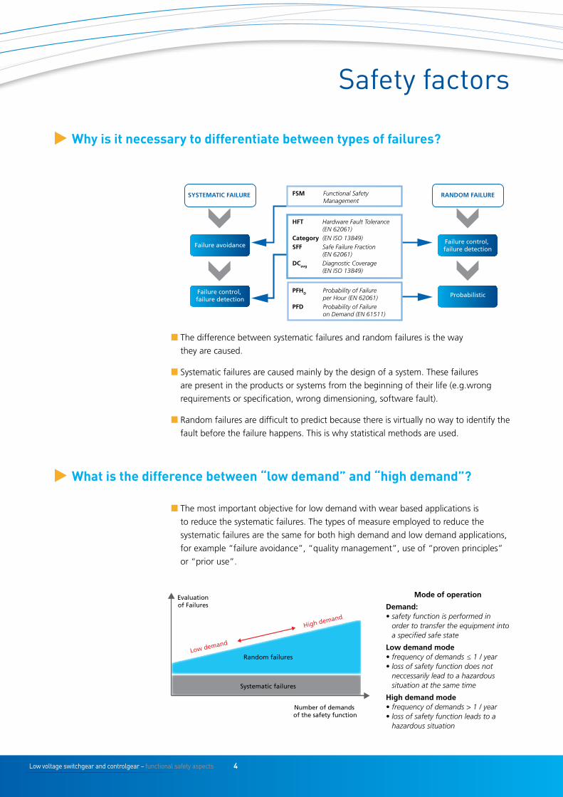
n The difference between systematic failures and random failures is the way
they are caused.
n Systematic failures are caused mainly by the design of a system. These failures
are present in the products or systems from the beginning of their life (e.g.wrong
requirements or specification, wrong dimensioning, software fault).
n Random failures are difficult to predict because there is virtually no way to identify the
fault before the failure happens. This is why statistical methods are used.
n The most important objective for low demand with wear based applications is
to reduce the systematic failures. The types of measure employed to reduce the
systematic failures are the same for both high demand and low demand applications,
for example “failure avoidance”, “quality management”, use of “proven principles”
or “prior use”.
t Why is it necessary to differentiate between types of failures?
t What is the difference between “low demand” and “high demand”?
HFT Hardware Fault Tolerance (EN 62061)Category (EN ISO 13849)SFF Safe Failure Fraction (EN 62061)DCavg Diagnostic Coverage (EN ISO 13849)
PFHD Probability of Failure per Hour (EN 62061)PFD Probability of Failure on Demand (EN 61511)
SYSTEMATIC FAILURE
Failure avoidance
Failure control, failure detection
RANDOM FAILUREFSM Functional Safety Management
Failure control, failure detection
Probabilistic
Evaluation of Failures
Number of demands of the safety function
Random failures
Systematic failures
Low demand
High demand
Mode of operation
Demand: • safety function is performed in
order to transfer the equipment into a specified safe state
Low demand mode• frequency of demands ≤ 1 / year• loss of safety function does not
neccessarily lead to a hazardous situation at the same time
High demand mode• frequency of demands > 1 / year• loss of safety function leads to a
hazardous situation
Safety factors
5 Low voltage switchgear and controlgear – functional safety aspects
Responsibilities
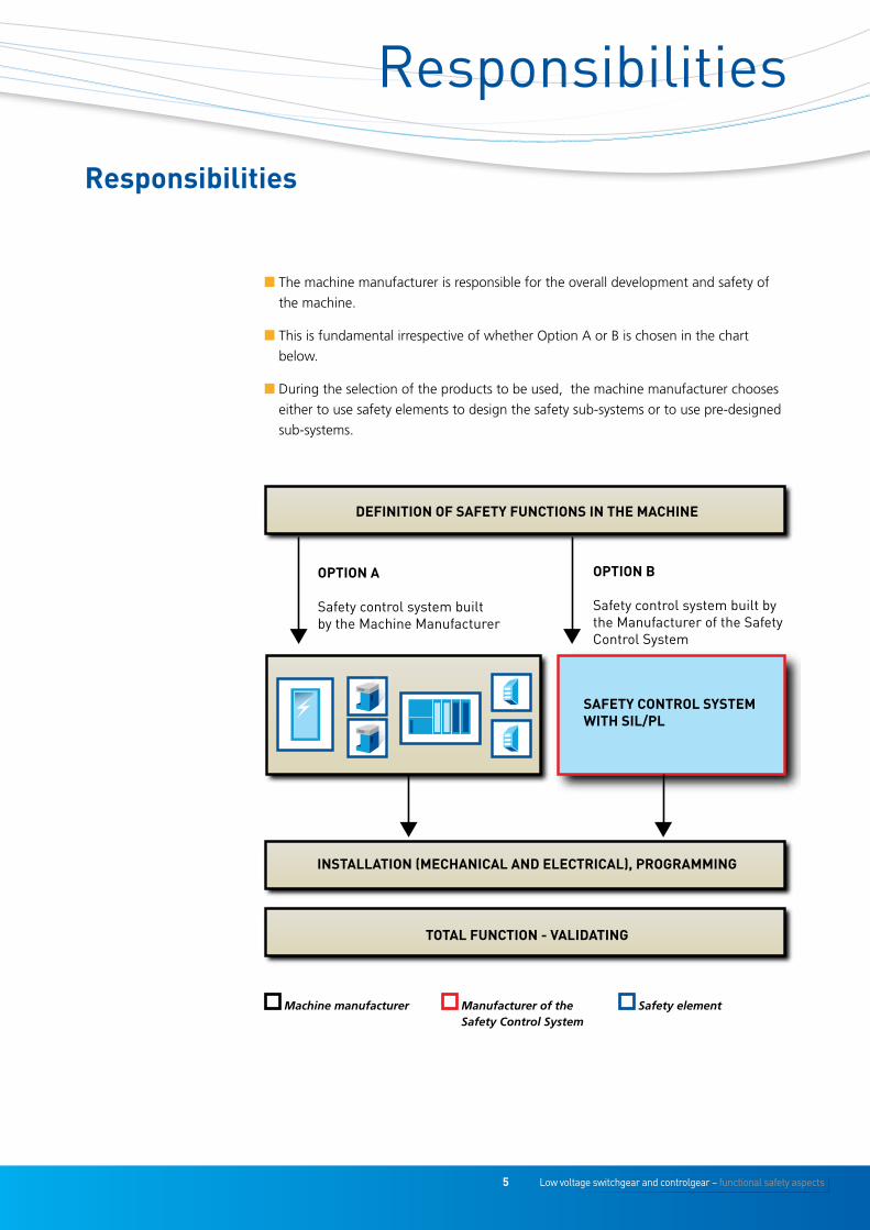
n The machine manufacturer is responsible for the overall development and safety of
the machine.
n This is fundamental irrespective of whether Option A or B is chosen in the chart
below.
n During the selection of the products to be used, the machine manufacturer chooses
either to use safety elements to design the safety sub-systems or to use pre-designed
sub-systems.
DEFINITION OF SAFETY FUNCTIONS IN THE MACHINE
INSTALLATION (MECHANICAL AND ELECTRICAL), PROGRAMMING
TOTAL FUNCTION - VALIDATING
OPTION A
Safety control system built by the Machine Manufacturer
OPTION B
Safety control system built by the Manufacturer of the Safety Control System
SAFETY CONTROL SYSTEM WITH SIL/PL
Machine manufacturer Manufacturer of the Safety Control System
Safety element
Responsibilities
Low voltage switchgear and controlgear – functional safety aspects 6
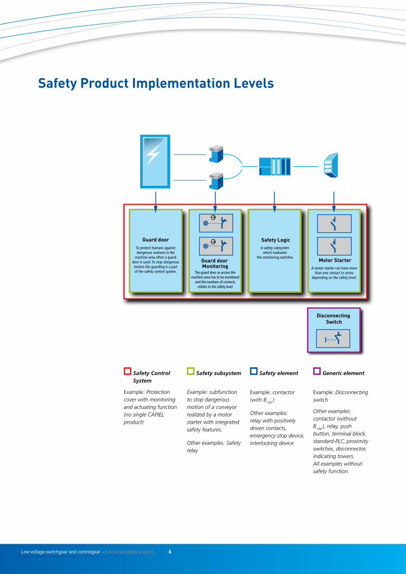
Guard door
Guard door Monitoring
Safety Logic
Motor Starter
Disconnecting Switch
To protect humans against dangerous motions in the
machine area often a guard door is used. To stop dangerous motion the guarding is a part of the safety control system. The guard door as access the
machine area has to be monitored and the numbers of contacts
relates to the safety level
A safety subsystem which evaluates
the monitoring switches
A motor starter can have more than one contact in series
depending on the safety level.
Safety Control System
Example: Protection cover with monitoring and actuating function (no single CAPIEL product)
Safety subsystem
Example: subfunction to stop dangerous motion of a conveyor realized by a motor starter with integrated safety features.
Other examples: Safety relay
Safety element
Example: contactor (with B10d )
Other examples: relay with positively driven contacts, emergency stop device, interlocking device.
Generic element
Example: Disconnecting switch
Other examples: contactor (without B10d ), relay, push button, terminal block, standard-PLC, proximity switches, disconnector, indicating towers. All examples without safety function.
Safety Product Implementation Levels
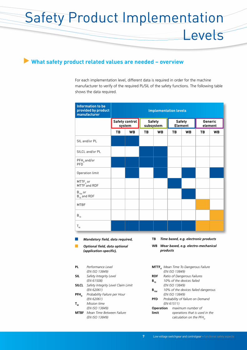
7 Low voltage switchgear and controlgear – functional safety aspects
t What safety product related values are needed – overview
Information to be provided by product manufacturer
Implementation levels
Safety control system
Safety subsystem
Safety Element
Generic element
tb Wb tb Wb tb Wb tb Wb
SIL and/or PL
SILCL and/or PL
PFHD and/or PFD
Operation limit
MTTFd or MTTF and RDF
B10d or B10 and RDF
MTBF
B10
TM
Mandatory field, data required,
Optional field, data optional (application-specific),
Tb Time based, e.g. electronic products
wb Wear based, e.g. electro-mechanical products
PL Performance Level (EN ISO 13849)
SiL Safety Integrity Level (EN 61508)
SiLcL Safety Integrity Level Claim Limit (EN 62061)
PFHD Probability Failure per Hour (EN 62061)
TM Mission time (EN ISO 13849)
MTbF Mean Time Between Failure (EN ISO 13849)
MTTFd Mean Time To Dangerous Failure (EN ISO 13849)
RDF Ratio of Dangerous Failuresb10 10% of the devices failed
(EN ISO 13849)b10d 10% of the devices failed dangerous
(EN ISO 13849)PFD Probability of failure on Demand
(EN 61511)Operation maximum number of limit operations that is used in the calculation on the PFHD
Safety Product Implementation Levels
For each implementation level, different data is required in order for the machine
manufacturer to verify of the required PL/SIL of the safety functions. The following table
shows the data required.
Low voltage switchgear and controlgear – functional safety aspects 8
Case Study
A movable protective guard is monitored by
means of a door monitoring switch (may be two
depending on required PL/SIL) with a separate
actuator.
Conditions in this example:
n This guard is opened four times per hour,
(C=4).
n Architecture is a two channel
n B10 = 1 000 000
n RDF = 20%
n CCF, b = 10% (Common Cause Factor
EN 62061)
n T1 = 20 year (Proof Test Interval EN 62061)
≈ 200 000 hours
n DC = 0
calculation of the SiL claim for the safety subsystem 1:
Ratio of Dangerous Failure (RDF) and the B10 are given by the product standard or the
manufacturer, e.g. 20% and 1 000 000*. The B10d value used in EN ISO 13849 can be
determined as follows:
The total failure rate λD according EN/IEC 62061 of the position switch is as follows:
In this example the function of the sensors is not monitored, therefore λDD=0. Also λS =0,
this is because “not closing faults” are not part of the safety function and are therefore not
relevant for the SFF calculation. SFF = (λDD+ λS)/ (λD+ λS) = (0+0)/(8 x 10-8 +0)= 0
For calculation of SFF only failures relevant for the safety function should be used.
The no effect failure is not used for SFF calculations**.
PFHD ≈ 2*λD2 *T1/2+b*λD
PFHD ≈ 2*(8 x 10-8)2*200 000/2+0,1*8 x 10-8= 8 x 10⁻⁹ [1/h]
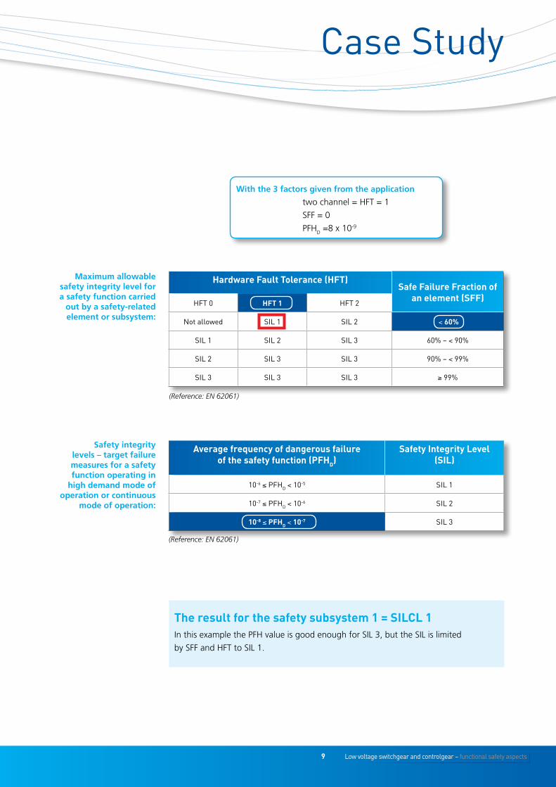
Case Study: High Demand Application
B10d = B10 =
1 000 000 = 5 000 000
RDF 0.2
λD= 0.1 x C
= 0.1 x 4
= 8 x 10⁻⁸
B10d 5 000 000
*See also “CAPIEL WHITE PAPER, Low voltage controlgear products and functional safety”, www.capiel.eu.**See also EN 61508-4 2nd Ed subclause 3.6.14/15
Picture Eaton Industries GmbH
9 Low voltage switchgear and controlgear – functional safety aspects
the result for the safety subsystem 1 = SILCL 1In this example the PFH value is good enough for SIL 3, but the SIL is limited
by SFF and HFT to SIL 1.
Case Study
with the 3 factors given from the application
two channel = HFT = 1
SFF = 0
PFHD =8 x 10⁻⁹
Maximum allowable safety integrity level for a safety function carried
out by a safety-related element or subsystem:
Hardware Fault tolerance (HFt)Safe Failure Fraction of
an element (SFF)HFT 0 HFt 1 HFT 2
Not allowed SIL 1 SIL 2 < 60%
SIL 1 SIL 2 SIL 3 60% – < 90%
SIL 2 SIL 3 SIL 3 90% – < 99%
SIL 3 SIL 3 SIL 3 ≥ 99%
(Reference: EN 62061)
Safety integrity levels – target failure measures for a safety function operating in
high demand mode of operation or continuous
mode of operation:
Average frequency of dangerous failure of the safety function (PFHD)
Safety Integrity Level (SIL)
10-6 ≤ PFHD < 10-5 SIL 1
10-7 ≤ PFHD < 10-6 SIL 2
10-8 ≤ PFHD < 10-7 SIL 3
(Reference: EN 62061)
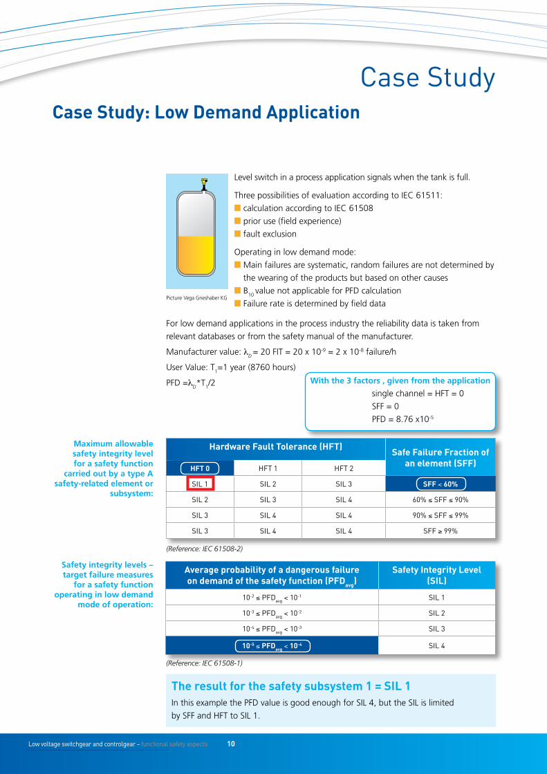
Low voltage switchgear and controlgear – functional safety aspects 10
For low demand applications in the process industry the reliability data is taken from
relevant databases or from the safety manual of the manufacturer.
Manufacturer value: λD = 20 FIT = 20 x 10-9 = 2 x 10⁻⁸ failure/h
User Value: T1=1 year (8760 hours)
PFD =λD*T1/2
the result for the safety subsystem 1 = SIL 1In this example the PFD value is good enough for SIL 4, but the SIL is limited
by SFF and HFT to SIL 1.
Case Study: Low Demand Application
Case Study
Level switch in a process application signals when the tank is full.
Three possibilities of evaluation according to IEC 61511:
n calculation according to IEC 61508
n prior use (field experience)
n fault exclusion
Operating in low demand mode:
n Main failures are systematic, random failures are not determined by
the wearing of the products but based on other causes
n B10 value not applicable for PFD calculation
n Failure rate is determined by field data
Maximum allowable safety integrity level for a safety function
carried out by a type A safety-related element or
subsystem:
Hardware Fault tolerance (HFt)Safe Failure Fraction of
an element (SFF)HFt 0 HFT 1 HFT 2
SIL 1 SIL 2 SIL 3 SFF < 60%
SIL 2 SIL 3 SIL 4 60% ≤ SFF ≤ 90%
SIL 3 SIL 4 SIL 4 90% ≤ SFF ≤ 99%
SIL 3 SIL 4 SIL 4 SFF ≥ 99%
(Reference: IEC 61508-2)
Safety integrity levels – target failure measures
for a safety function operating in low demand
mode of operation:
Average probability of a dangerous failure on demand of the safety function (PFDavg)
Safety Integrity Level(SIL)
10-2 ≤ PFDavg < 10-1 SIL 1
10-3 ≤ PFDavg < 10-2 SIL 2
10-4 ≤ PFDavg < 10-3 SIL 3
10-5 ≤ PFDavg < 10-4 SIL 4
(Reference: IEC 61508-1)
with the 3 factors , given from the application
single channel = HFT = 0
SFF = 0
PFD = 8.76 x10⁻⁵
Picture Vega Grieshaber KG
11 Low voltage switchgear and controlgear – functional safety aspects
Conclusions & References
References
Conclusions
en 61508 Functional safety of electrical/electronic/programmable electronic safety-related systems
en 62061 Safety of machinery – Functional safety of safety-related electrical, electronic and programmable electronic control systems
en 61511 Functional safety – Safety instrumented systems for the process industry sector
en iSO 13849-1 Safety of machinery – Safety-related parts of control systems Part 1: General principles for design
en iSO 13849-2 Safety of machinery – Safety-related parts of control systems Part 2: Validation
en 60947-series Low-voltage switchgear and controlgear
en 61649 Weibull analysis
VDMA 66413 VDMA-Specification
en 50495 Safety devices required for the safe functioning of equipment with respect to explosion risks
en 50155 Railway applications – Electronic equipment used on
rolling stock
n The machine manufacturer is responsible for the overall development and safety of
the machine.
n When designing a machine, the manufacturer can:
n Select an appropriate safety control system for his application. The safety control
system supplier will provide relevant functional safety data.
nSelect and combine suitable safety subsystems in order to create a safety control
system that provides the required level for a safety function.
nDesign a subsystem using safety elements and combine it with other subsystems to
create a safety control system that provides the required level for a safety function.
n If a generic element is used in a safety related application, the machine manufacturer
has to justify its usage as a safety element. This includes deriving all functional safety
values and ensuring its suitability for the intended function.
The table on page 7 shows which safety related values will be provided by the
component manufacturer.
n Probabilistic determination methods are not always suitable when evaluating reliability.
Therefore a systematic analysis of all possible sources of failure of the system and its
components shall always be carried out before designing the system.
n The calculation is just one of a range of verification measures that are required to
show that a sufficient safety level has been achieved.
n Probabilistic values for random failures in low demand mode are provided by the
manufacturer or taken from relevant databases or field data.
n Some examples of common databases:
n Exida Electrical & Mechanical
Component Reliability Handbook
n MIL HDBK 217F
n NAMUR NE 93
n RAC FMD 91
n SN29500
n SN31920
n VDE 2180
n IEC/TR 62380
n IEC 61709
n White paper CAPIEL PG5

CAPIEL Members
www.capiel.eu
CAPIEL at a glance
CAPIEL represents 9 national associations from 8 European countries comprising more than 550 manufacturers.
Members of national associations represented by CAPIEL include small, medium and large-sized
companies employing 120,000 people directly in Europe and have a combined
turnover of €18.25 billion.
CAPIEL membership includes global players such as Siemens, Schneider Electric, ABB, Eaton,
Rockwell Automation, etc.