lowest power, smallest size rtk receiver...
TRANSCRIPT
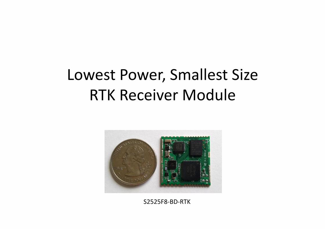
Lowest Power, Smallest Size
RTK Receiver Module
S2525F8-BD-RTK

“S2525F8-BD-RTK” OEM RTK Module
• Support RTK base and rover modes
• GPS L1 + BDS B1 + SBAS
• Tracks up to 28 satellites
• Position accuracy: autonomous 2.5m, RTK cm-level
• Sensitivity: -148dBm cold start, -160dBm tracking
• Receiver Autonomous Integrity Monitoring (RAIM)
• AGPS support
• 25mm x 25mm, 300mW
Mode Output Output Baud Rate Input Input Baud Rate
Rover NMEA-0183 115200 RTCM-SC104 3.0, 3.1
or SkyTraq-Raw
115200
Base SkyTraq-Raw 115200
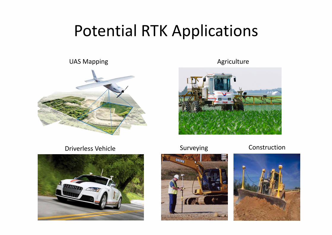
Potential RTK Applications
UAS Mapping
ConstructionSurveying
Agriculture
Driverless Vehicle

Baseline vs Accuracy
Baseline 0.5km TTAF 1 minute
Accuracy 0.8 cm R95 (300sec)
Baseline 1km TTAF 1.5 minutes
Accuracy 0.6c m R95 (300sec)
Baseline 1.5km TTAF 2 minutes
Accuracy 0.7 cm R95 (300sec)Baseline 6.3km TTAF 2.4 minutes
Accuracy 1.0 cm R95 (300sec)
Rover Antenna: TW2710
Test Environment: Open Sky
Mode: Real-Time
A. Testing done by road side around
8:50AM with cars passing by or
stopping for red light, thus result
noisier even with shorter base line
B. Testing done on roof of a 20 floor
building around 6:25AM
C. Testing done by road side around
11:20PM without cars passing by
D. Testing done in an empty parking lot
around 9:30AM
TTAF: Time To Ambiguity Fixed

Performance Comparison (1/6)
TTAF (sec)
15 meter baseline
HX-CSX601A antenna
Power on 900sec, off 10sec
10 hour testing
S2525F8-BD-RTK GPS/BDS mode
UTC time
Plot of all RTK fix points
(0,0) is true location

Performance Comparison (2/6)testing another brand single-frequency GPS/GLONASS RTK receiver
2.4 meter baseline
Antenna: TW2710
Power on up to 900sec, off 10sec
12 hour testing
Time-To-Ambiguity-Fixed
(sec, when converged to true location)
UTC time
1 time no RTK fix solution in 900sec
Plot of all RTK fix points
(0,0) is true location

2.4 meter baseline
Antenna: TW2710
Power on 900sec, off 10sec
12 hour testing
1st column: time to get 1st RTK fix solution
2nd column: time that RTK fix solution converged to true location
Yellow color: trials that has RTK fix solution matching true location from beginning
Performance Comparison (3/6)testing another brand single-frequency GPS/GLONASS RTK receiver

17 meter baseline
Antenna: HX-CXS601A
7 hour testing
Performance Comparison (4/6)testing another brand GPS/GLONASS raw measurement receiver + RTKLIB
1 time no RTK fix solution in 900sec
Time-To-Ambiguity-Fixed
(sec, when converged to true location)
Plot of all RTK fix points
(0,0) is true location

Performance Comparison (5/6)
TTAF (sec)
15 meter baseline
Antenna: HX-CSX601A
Power on 900sec, off 10sec
10 hour testing
S2525F8-BD-RTK GPS-only mode
UTC time
4 time no RTK fix in 900sec in GPS-only mode due to
less available satellite. We are still improving firmware
performance to see how much it could be improved
3 time deviation
in decimeters
Plot of all RTK fix points
(0,0) is true location

• Unlike consumer GPS that works nearly everywhere, RTK receiver works only outdoors under open-sky with very little interference
• With dual-satellite system, single frequency RTK receiver can have varying TTAF as seen on page-5, page-6, and page-8
• With GPS-only single frequency RTK receiver, it may sometimes unable to get RTK fix solution or may have deviated RTK fix solution due to too few usable GPS satellites
• As Beidou (BDS) system is not fully operational yet, users outside Asia will see lesser total number of satellites and performance will be between GPS-only mode and GPS/BDS mode as shown on page-5 and page-9.
• S2525F8-BD-RTK receiver performance will be better than any existing single-frequency GPS RTK receiver on the market due to additional Beidousatellites that it could use.
• GNSS Radar may be used to find out about the satellite situation in your region: http://www.taroz.net/GNSS-Radar.html
Performance Comparison (6/6)

Accuracy: GPS vs DGPS vs RTK
RTK, 3 diff days
1.5Km baseline
DGPS, 2 diff days
GPS, 2 diff days
Other brand GPS
on another day
RTK receiver tested on 3 different days, tracks overlap.
Its tracks serve as reference track for comparison.
DGPS result is near reference track, but don’t over lap well.
GPS result deviates on different day due to atmospheric delay
error, don’t overlap well.
Other brand GPS result deviates on different pass in a testing
on the same day, don’t overlap well.

Performance on Heavy Rainy Day
4.5km baseline, testing on a severe rainy day, getting mostly float solution
Section A: car drove on adjacent 3 lanes separated roughly 2 meters apart
Section B: car drove on the same lane on each pass
Although it’s mostly float solution with small number of fixed solution, the 3 tracks
on section A are distinctively on separate lanes running in parallel, and the 3 tracks
on section B roughly overlap, nearly as good as from fixed solution
Notice how the tracks look distinctly accurate and different from the GPS results
shown in previous slide even when the result is mostly float solution

Dynamic Performance
Max speed 81Km/hr, 1.7Km baseline, blue : single, yellow : float, green : fixed

GPS Receiver
• Most GPS receivers use C/A code to measure
position
• A C/A code chip is roughly 300 meters
• GPS receiver can determine position with
resolution to fraction of a C/A code chip, resulting
in 2.5 meter CEP 50%* accuracy from 4 or more
GPS satellites
* 2.5m CEP 50% means 50% of the location points fall within 2.5m radius.
It is equivalent to 95% confidence level falling within 5 meter radius

GPS Receiver Error
A rectangular land with 4 corners
measured using GPS at different time on
different days. When plotted on Google
Earth, these 4 measured corners defined
rectangular lands may have area shifted
by 0 ~ +/-5 meters.
Shifted 10 meters for the worst case +5m
and -5m shifts.
This is mostly due to ionosphere and
troposphere delays.
RTK GPS Receiver (1/2)
• RTK GPS receiver counts carrier cycles to
determine relative position from base station
• Each carrier cycle has wave length of 19cm
• RTK receiver can determine relative position
from base station with resolution to fraction of
a carrier wavelength, resulting in centimeter-
level position accuracy

RTK Receiver (2/2)
rover’s relative distance from base is accurate to centimeter level
If base position* is accurate to millimeter � rover position* will be accurate to centimeters
If base position* is accurate only to meters � rover position* will only be accurate to meters
but relative distance from base is still accurate
to centimeters
* position refers to the latitude and longitude numbers reported by base or rover

Usage Configuration 1
using
S2525F8-BD-RTK
as rover
NTRIP
Client
RTCM
3.x
cm-level accuracy
NMEA output

Usage Configuration 2 1/4
using
S2525F8-BD-RTK
as rover
wireless
receiver
cm-level accuracy
relative to base
NMEA
output
using
S2525F8-BD-RTK
as base station
carrier phase raw
measurement
wireless
transmitter
carrier phase raw
measurement

Usage Configuration 2 2/4
• If a known surveyed point exists with
centimeter position accuracy, placing base
station S2525F8-BD-RTK antenna there, and
enter the location coordinates into S2525F8-
BD-RTK, then the rover NMEA output will have
cm-level position accuracy.

RTK Usage Configuration 2 3/4
• If no known surveyed point exists, place the base station S2525F8-BD-RTK antenna at some fixed location that is to be later used as reference point.
• After base station S2525F8-BD-RTK self-surveyed, take note of the latitude/longitude location reported, to be entered as base station location for future use; also mark the physical location of the reference point for future use.
• Using this method, the rectangular land defined by 4 corners measured by GPS receiver that we shown earlier, if measured using RTK receiver over many different days, will only have area shifted in centimeters on Google Earth, not 10 meter!

Usage Configuration 2 4/4
base station location
(X, Y) (X + 3315.78λ, Y )
(X, Y+2052.63λ ) (X + 3315.78λ, Y+2052.63λ )
With base set at a fixed location, the RTK rover determines the other three corner locations as
#1: 3315.78 wavelength to the right
#2: 2052.63 wavelength to the north
#3: 3315.78 wavelength to the right and 2052.63 wavelength to the north
Once base (X,Y) is given a fixed coordinate, when RTK rover measures the other 3 corner
coordinates at different days, the results will only differ by fractional wavelength, yielding
centimeter-level accuracy relative to the base.
With this kind of rover-to-base relative positioning application, once base is set at a fixed
location, accuracy of the (X,Y) coordinate that we measured, meter or centimeter, is not
important, so long as the same (X,Y) coordinate number is used for base location, and base
antenna is placed at same location afterwards when using rover to measure position.
For short baseline open-sky relative positioning
application, lower-cost single-frequency RTK receiver
could be used, a considerable cost saving from
alternative multi-frequency RTK receivers.
#1
#2 #3

Setup as Rover
• From GNSS Viewer*
Venus8 � RTK � Configure RTK Mode � RTK rover mode
* Using SkyTraq GNSS Viewer
V2.0.166 or higher

Setup as Base (1/2)
• From GNSS Viewer
Venus8 � RTK � Configure RTK Mode � RTK base mode

Setup as Base (2/2)
• From GNSS Viewer
1PPS Timing � Configure Timing � Static (input base position)

Application Example 1
• Precision Machine Control
Once coordinates of the polygon corners are determined by the rover, precision steering of machine can be controlled by the autopilot software using the cm-level accuracy position provided by the RTK rover

Application Example 2
• Precision Aerial Imaging
– RTK rover equipped UAV can take photo at predefined
locations, centimeter-level exact, resulting in images that
are always taken at the right spot, always consistent.
– Acquire same amount of image data when flying against
or with the wind.

• BDS is not defined in RTCM 3.x spec yet. Each company has proprietary RTCM 3.x base-station BDS implementation. So limited compatibility with existing base station for BDS initially, but GPS portion is compatible. We’ll provide support for additional different brand BDS base station as more information becomes available.
• GLONASS inter-channel bias is known to cause compatibility issue for different brand base & rover GPS/GLONASS RTK receivers, causing GLONASS portion not working for RTK when using rover with different brand base-station. Thus GPS/GLONASS RTK receiver will only have GPS satellites for RTK when used with different brand public base stations; in same situation as GPS/BDS RTK receiver could only use GPS satellites for RTK in US or Europe when connecting to public base station.
• When same RTK receivers are used for base and rover, then all receivable signals in the two satellite navigation systems can be used.
Known Issue

Lowest Power, Smallest Size
Empower your outdoor machine control, UAV aerial
imaging, or GIS data collection applications with
centimeter-level accuracy RTK technology !