lp-sw902fgp · lpsw902fgp_tst_enb01w lp-sw902fgp 9 port midspan poe ethernet switch with 8x10/100m...
TRANSCRIPT

Active Products - Switches
www.lanpro.com
LPSW902FGP_TST_ENB01W
LP-SW902FGP 9 port Midspan PoE Ethernet Switch with 8x10/100M PoE ports plus 1x10/100/1000M copper port interchangeable with 1x SFP Gigabit port.
Power Over Ethernet output specifications test.
The purpose of this test is to stress the device near its maximum values at an ambient temperature of approximately 24ºC during two sessions of 9 hours each.
At the same time, the hottest temperature will be observed on the PoE Output driver circuitry heat sink to see if it exceeds expected values.
Tests will be performed at low AC input line voltage near 100 VAC. This will stress the power supply because current will rise to maintain the power output.
All outputs will be loaded so as to be near the 112W maximum Power specified at room temperature.
LP-SW902FGP 9 port Midspan PoE Ethernet Switch with
8x10/100M PoE ports plus 1x10/100/1000M copper port interchangeable with 1x SFP Gigabit port. Power Over Ethernet output specifications test.

www.lanpro.com
Active Products - Switches - Rack Series - LP-SW902FGP 9 port Midspan PoE Ethernet Switch with 8x10/100M PoE ports plus 1x10/100/1000M copper port interchangeable with 1x SFP Gigabit port.
Power Over Ethernet output specifications test
Bench Test Setup
Test schematic with results
A
B
2
a.- One (1) Current and Over-Voltage Protected Power Distribution Unit Model LP-RU07107PPDU.
b.- One (1) B&K Precision Model 1653A Isolation Transformer and Variac.
c.- One (1) Cable fixture for Line Voltage and Input current measurement.
d.- One (1) Power Clamp B&K Precision Model 5330A.
e.- One (1) Dual K-Type Thermometer B&K Precision Model 630.
f.- One (1) LanPro LP-SW902FGP PoE Switch.
g.- Eight 0.5 m LanPro CAT 5e Patch Cords.
h.- Eight (8) LP-PoE151 802.3af PoE splitters with the output set to 12VDC.
i.- Eight (8) PoE Splitter cables for connection to Resistor Loads.
j.- One (1) 24 Port Resistive Load.
k.- One (1) test fixture for measuring Ethernet port PoE current and voltage output.
l.-Two (2) B&K Precision Model 390A Multimeters with Test Leads.
m.-One LP-PoE151 PoE Splitter output current and voltage measurement cable and terminal test fixture.
The test setup shown in Figure 1 includes the following parts:
Figure 1

www.lanpro.com
Active Products - Switches - Rack Series - LP-SW902FGP 9 port Midspan PoE Ethernet Switch with 8x10/100M PoE ports plus 1x10/100/1000M copper port interchangeable with 1x SFP Gigabit port.
Power Over Ethernet output specifications test
Sequence of Testing
Initial Ambient temperature
Power line Voltage Power Line current
Input Voltage adjustment
C
3
One of the thermocouple input sensors is measuring free air temperature around the setup for comparisons purposes, Tamb= 23.6 ºC as shown in Figure 2.
We need to test the LP-SW902FGP with a low line voltage of about 100 VAC, larger than the -10% expected low. Actually, we assume a 16.25% less than the nominal 120 VAC for this test. Our measurement with the Power Meter is Vin: 100.5 VAC as shown in Figure 4.
The Line current is measured giving a Figure of 1.6 A for the loading conditions specified above, please see Figure 5.
For the adjustment of the input voltage, we have selected a Variac Auto-Transformer with an internal isolation transformer model 1653A by B&K Precision with a maximum current of 2 Ampere AC.
Figure 2
Figure 4. Input AC Voltage measured: 100.5 VAC Figure 5. Line Current Amperes read: 1.6 Ampere AC
Figure 3
1
3 4
2

www.lanpro.com
Active Products - Switches - Rack Series - LP-SW902FGP 9 port Midspan PoE Ethernet Switch with 8x10/100M PoE ports plus 1x10/100/1000M copper port interchangeable with 1x SFP Gigabit port.
Power Over Ethernet output specifications test
Real Power Measurement
Power Factor measurement
Apparent Power (Volt-Ampere)
Temperature difference between Tamb and Tair
4
The measured Real Power is 130 Watt as shown in Figure 6.
The measured Apparent Power is 0.17 (KVA).
A temperature Differential, Tdiff, between the ambient temperature and the air expelled by the Switch fans in the rear of the DUT stabilized around 9.7 degrees Centigrade and was measured after 4 hours.
Figure 6. Real Power=0.13 (KWatt)
Figure 8. Power Factor=0.8
Figure 7. Apparent Power measurement is 0.17 KVA
Figure 9. Temperature differential after 4 hours= 9.7°C
5
7
6
8
The power factor measured is: 0.8.
www.lanpro.com
Active Products - Switches - Rack Series - LP-SW902FGP 9 port Midspan PoE Ethernet Switch with 8x10/100M PoE ports plus 1x10/100/1000M copper port interchangeable with 1x SFP Gigabit port.
Power Over Ethernet output specifications test
LP-SW902FGP Switch front view showing led indications
PoE Splitters connections for powering the resistive load.
Resistive load
Measurement of PoE Port voltage and current
5
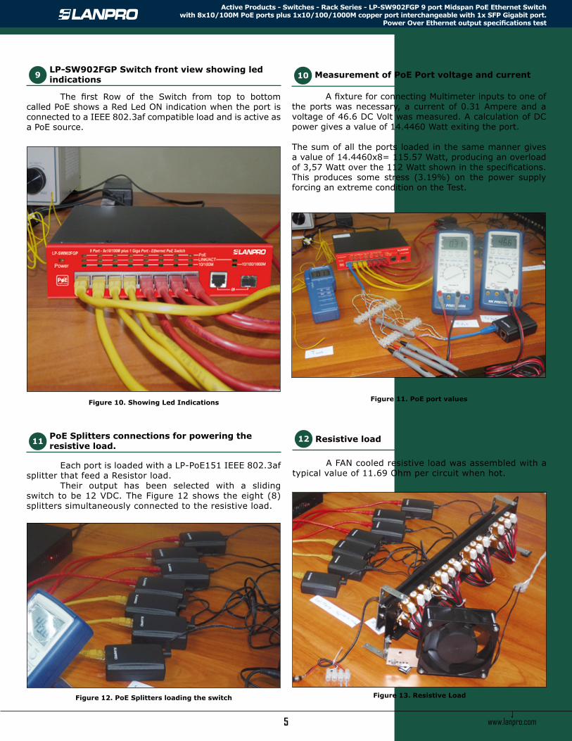
The first Row of the Switch from top to bottom called PoE shows a Red Led ON indication when the port is connected to a IEEE 802.3af compatible load and is active as a PoE source.
Each port is loaded with a LP-PoE151 IEEE 802.3af splitter that feed a Resistor load. Their output has been selected with a sliding switch to be 12 VDC. The Figure 12 shows the eight (8) splitters simultaneously connected to the resistive load.
A FAN cooled resistive load was assembled with a typical value of 11.69 Ohm per circuit when hot.
A fixture for connecting Multimeter inputs to one of the ports was necessary, a current of 0.31 Ampere and a voltage of 46.6 DC Volt was measured. A calculation of DC power gives a value of 14.4460 Watt exiting the port.
The sum of all the ports loaded in the same manner gives a value of 14.4460x8= 115.57 Watt, producing an overload of 3,57 Watt over the 112 Watt shown in the specifications. This produces some stress (3.19%) on the power supply forcing an extreme condition on the Test.
Figure 10. Showing Led Indications
Figure 12. PoE Splitters loading the switch Figure 13. Resistive Load
Figure 11. PoE port values
9
11 12
10

www.lanpro.com
Active Products - Switches - Rack Series - LP-SW902FGP 9 port Midspan PoE Ethernet Switch with 8x10/100M PoE ports plus 1x10/100/1000M copper port interchangeable with 1x SFP Gigabit port.
Power Over Ethernet output specifications test
Load measurements
Results
Power Supply temperature
6
The splitter output was measured and gave a typical value for one port of 11.74 VDC and 1.09 ADC, a DC Power of 12.79 W results.
Temperature of the power supply was measured after several hours of operation and was 56.3ºC.
Figure 14. Load measurements Figure 15
13
15
14
AC input
Active Power AC (W) 130
Apparent Power AC (VA) 170
Power factor AC (PF) 0.8
Input Voltage AC (V) 100.5
Current Input (A) 1.6
Ethernet-PoE port
Vpoe Output Voltage DC (V) 46.6
Ipoe Output Current DC (A) 0.31
Ppoe DC Power (W) 14.4460
Splitter output to RL
Output Voltage DC (V) 11.74
Output Current DC (A) 1.09
DC Power (W) 12.79
Ethernet-PoE ports output power sum 8 x (Ppoe) (W) 115.57
Temperature difference 4 hours (ºC) 9.7
Power Supply Temperatur Tps (ºC) 56.3
PoE Part Heat Sink Maximun Temperature (ºC) 70.0
www.lanpro.com
Active Products - Switches - Rack Series - LP-SW902FGP 9 port Midspan PoE Ethernet Switch with 8x10/100M PoE ports plus 1x10/100/1000M copper port interchangeable with 1x SFP Gigabit port.
Power Over Ethernet output specifications test
Conclusions
Safe loading
Example: Ambient temperature of operation: 35ºC
7
After this test we arrived to the following conclusions that can guide the user on how to safely operate the LP-SW902FGP.
The Switch performs inside design constraints and without elevated temperatures. The power supply is properly under-rated for operation at temperatures over 30 ºC.
Even though the Power Supply maximum rating is 200W, the sum of all ports shall not exceed the 112 W maximum rating at a 24ºC Tamb due to PoE port limitations. This is so in order to keep the Switch inside the safety operating area.
If you plan to operate this switch above 30ºC of ambient temperature, please derate linearly to 0 Watt @40ºC.
Before loading the switch ports with PoE compatible devices, calculate the sum of all the maximum loads applied to the switch outputs considering they are IEEE 802.3af compatible devices.
At 35ºC of ambient temperature you shall not load the switch with more than 92.2 Watt for the sum of all the outputs.
A maximum load per circuit shall be then: 7.0W @ up to 35ºC at each output port of the switch but you must take into consideration the DC resistance of the Cable to the Powered Device (PD), this will further reduce the available power to this remote device at the end of the cable path.
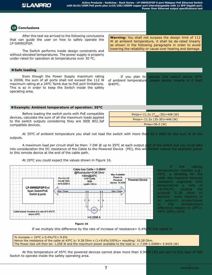
At 20ºC you could expect the values shown in Figure 16.
At this temperature of 45ºC the powered devices cannot draw more than 5.9420 [W] per port to this type of PoE Switch to operate inside the safety operating area.
If the cabling temperatures reaches e.g.: 45ºC, a derating for the cable also happens because resistance augments with temperature a rate of +0.4%/ºC, causing the original 9.38 Ohm to become more resistive in an amount proportional to the temperature difference respect to 20ºC= 45ºC-20ºC=25ºC
If we multiply this difference by the rate of increase of resistance= 0.4%/ºC the result is:
Figure 16
16
Pmax=-11.2x (Toper-30)+448 [W]
Pmax=-11.2x (35-30)+448 [W]
Pmax=56.0 [W]
% increase = 24ºC x 0.4%/ºC= 9.6%Hence the resistance of the cable at 45ºC is: 9.38 Ohm x (1+9.6%/100%)= resulting: 10.28 Ohm.The Power loss will then be: 1,058 W and the maximum power available to the load is: = 7.0W-1.058W= 5.9420 (W)
Warning: You shall not surpass the design limit of 112 W at ambient temperature, it shall be de-rated linearly as shown in the following paragraphs in order to avoid lowering the reliability or cause over heating and damage.