lpe 7-27
TRANSCRIPT

Low Profile 2G/3G/4G Antenna
The LPE antenna series is a range of low profile antennas incorporating a combination of wideband cellular elements covering 2G/3G and 4G frequencies in a robust compact housing.
Designed to be tough yet cost effective, the antennas are completely enclosed in a moulded housing made form weather and impact resistant plastic. The range is supplied with short fly leads and can be kitted with Panorama Antennas’ low loss extension cables in various lengths.
03/06/2015 v.1
Panorama Antennas LtdFrogmore, London, SW18 1HF, United Kingdom
T: +44 (0)20 8877 4444F: +44 (0)20 8877 4477
Waiver: The data given above is indicative of the performance of the product/s under particular conditions and does not imply a guarantee of performance. These specifications are subject to change without notice.Copyright © Panorama Antennas Ltd. All rights reserved.
LPE-7-27Low Profile LTE
Technical Drawing
Rugged Low Profile DesignWideband LTE-Cellular ElementWeatherproof Casing
Product Data
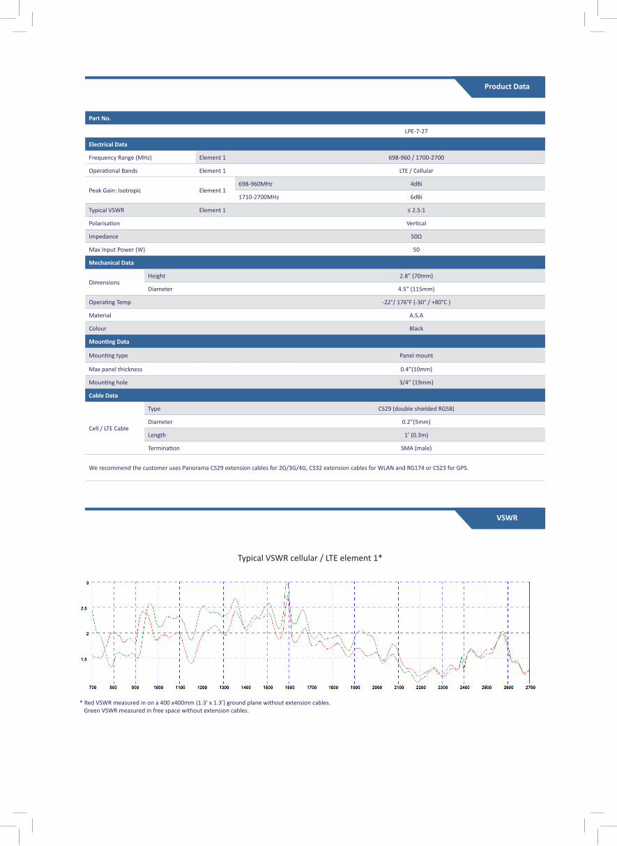
Part No.
LPE-7-27
Electrical Data
Frequency Range (MHz) Element 1 698-960 / 1700-2700
Operational Bands Element 1 LTE / Cellular
Peak Gain: Isotropic Element 1 698-960MHz 4dBi
1710-2700MHz 6dBi
Typical VSWR Element 1 ≤ 2.5:1
Polarisation Vertical
Impedance 50Ω
Max Input Power (W) 50
Mechanical Data
Dimensions Height 2.8” (70mm)
Diameter 4.5” (115mm)
Operating Temp -22°/ 176°F (-30° / +80°C )
Material A.S.A
Colour Black
Mounting Data
Mounting type Panel mount
Max panel thickness 0.4”(10mm)
Mounting hole 3/4” (19mm)
Cable Data
Cell / LTE Cable
Type CS29 (double shielded RG58)
Diameter 0.2”(5mm)
Length 1’ (0.3m)
Termination SMA (male)
We recommend the customer uses Panorama CS29 extension cables for 2G/3G/4G, CS32 extension cables for WLAN and RG174 or CS23 for GPS.
Typical VSWR cellular / LTE element 1*
* Red VSWR measured in on a 400 x400mm (1.3’ x 1.3’) ground plane without extension cables. Green VSWR measured in free space without extension cables.
VSWR

Typical 3D Pattern - Element 2 700MHz Typical 3D Pattern - Element 2 800MHz Typical 3D Pattern - Element 2 900MHz
Typical 3D Pattern - Element 2 1800MHz Typical 3D Pattern - Element 2 2000MHz Typical 3D Pattern - Element 2 2600MHz
N.B. All pattern and gain measurements taken on a 400 x 400mm (2’ x 2’) ground plane without additonal cable.
Typical H-Plane (700MHz) Typical H-Plane (800MHz) Typical H-Plane (900MHz) Typical H-Plane (1.7GHz)
Typical H-Plane (1.9GHz) Typical H-Plane (2.7GHz)
Product Data

Panorama Antennas LtdFrogmore, London, SW18 1HF, United Kingdom
T: +44 (0)20 8877 4444F: +44 (0)20 8877 4477
Waiver: The data given above is indicative of the performance of the product/s under particular conditions and does not imply a guarantee of performance. These specifications are subject to change without notice.Copyright © Panorama Antennas Ltd. All rights reserved.