lsis bus duct system catalog
DESCRIPTION
CatalogTRANSCRIPT
Leader in Electrics & Automation
Power Transmission & Distribution
LS Bus Duct System
2II
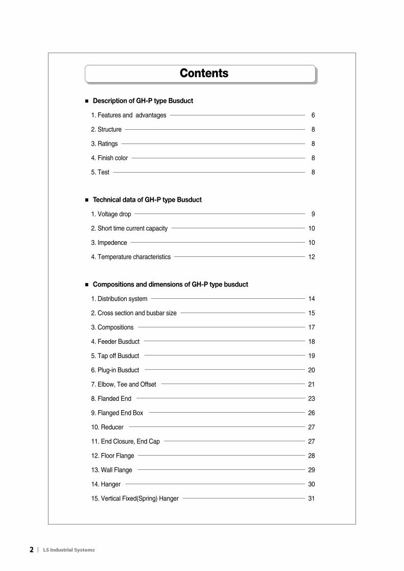
■ Description of GH-P type Busduct
1. Features and advantages 6
2. Structure 8
3. Ratings 8
4. Finish color 8
5. Test 8
■ Technical data of GH-P type Busduct
1. Voltage drop 9
2. Short time current capacity 10
3. Impedence 10
4. Temperature characteristics 12
■ Compositions and dimensions of GH-P type busduct
1. Distribution system 14
2. Cross section and busbar size 15
3. Compositions 17
4. Feeder Busduct 18
5. Tap off Busduct 19
6. Plug-in Busduct 20
7. Elbow, Tee and Offset 21
8. Flanded End 23
9. Flanged End Box 26
10. Reducer 27
11. End Closure, End Cap 27
12. Floor Flange 28
13. Wall Flange 29
14. Hanger 30
15. Vertical Fixed(Spring) Hanger 31
Contents
II3
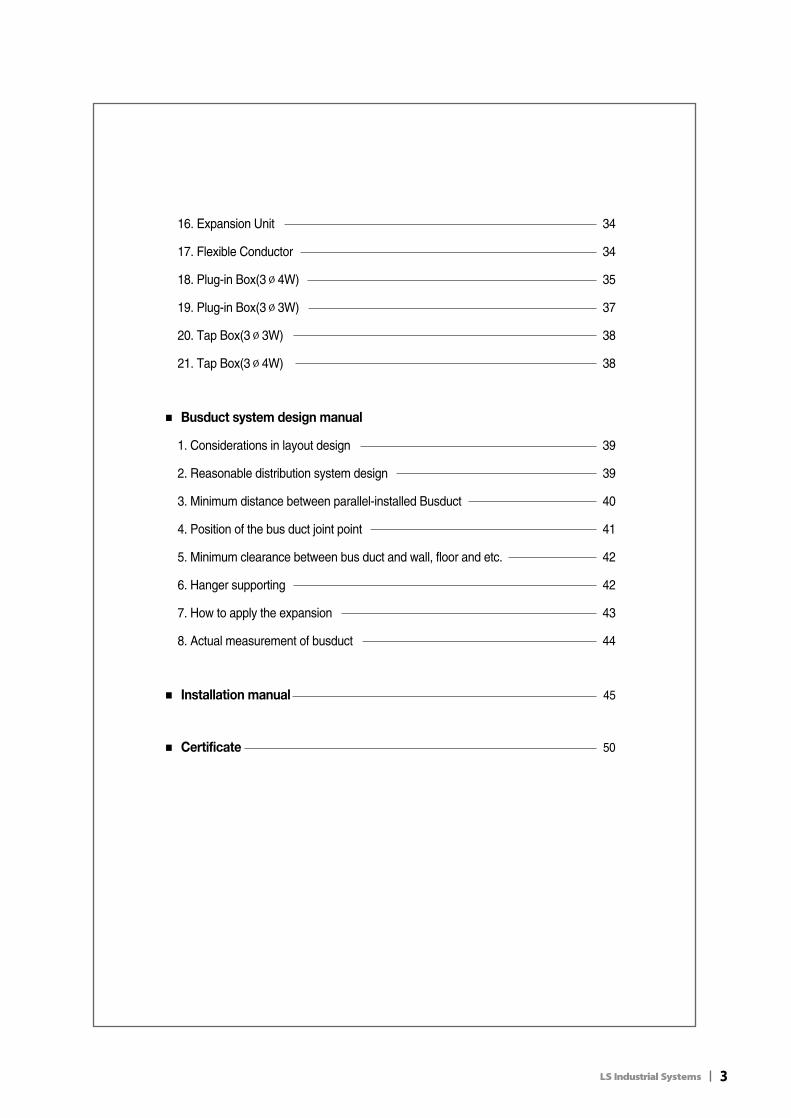
16. Expansion Unit 34
17. Flexible Conductor 34
18. Plug-in Box(3∅4W) 35
19. Plug-in Box(3∅3W) 37
20. Tap Box(3∅3W) 38
21. Tap Box(3∅4W) 38
■ Busduct system design manual
1. Considerations in layout design 39
2. Reasonable distribution system design 39
3. Minimum distance between parallel-installed Busduct 40
4. Position of the bus duct joint point 41
5. Minimum clearance between bus duct and wall, floor and etc. 42
6. Hanger supporting 42
7. How to apply the expansion 43
8. Actual measurement of busduct 44
■ Installation manual 45
■ Certificate 50
4II
1.Features and advantages of GH-P type Busduct
Description of GH-P type
1-1. Features (1) Insulation
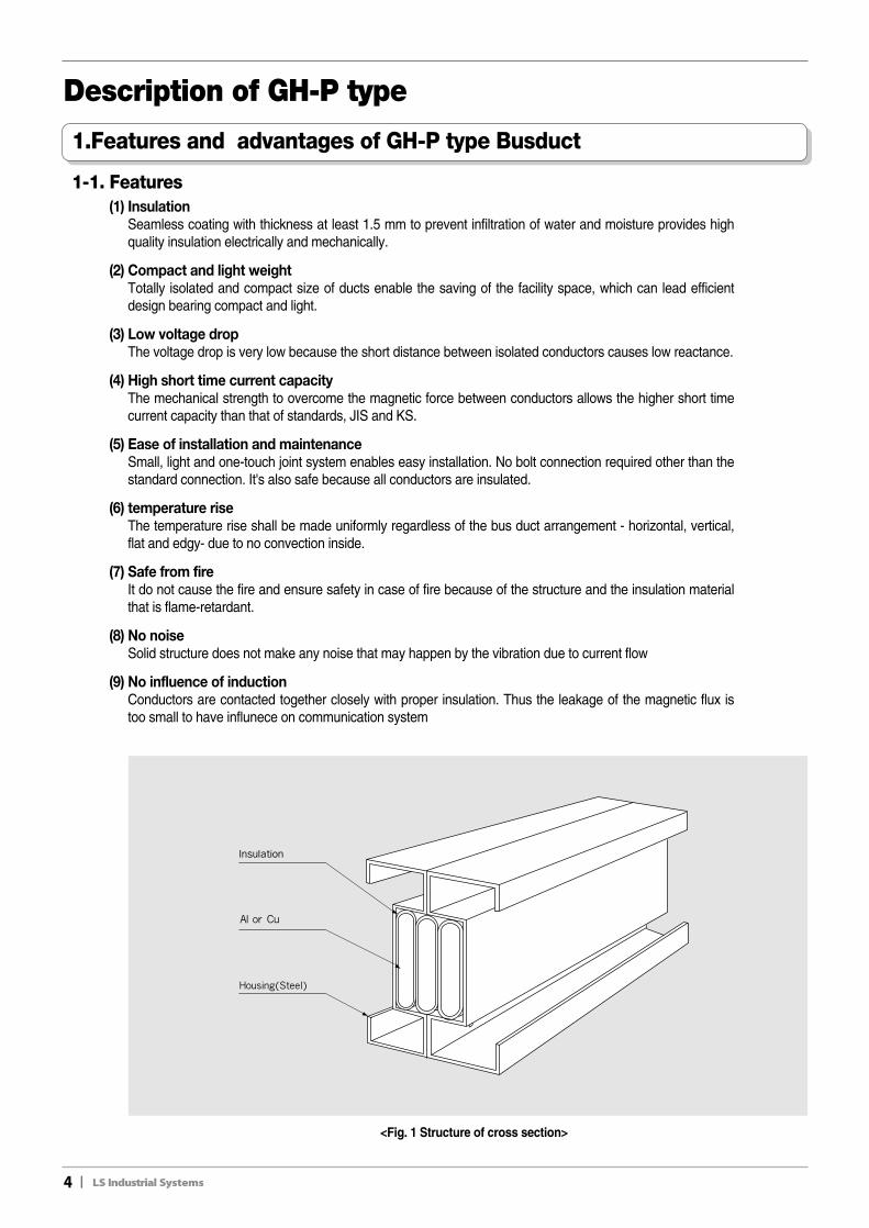
Seamless coating with thickness at least 1.5 mm to prevent infiltration of water and moisture provides highquality insulation electrically and mechanically.
(2) Compact and light weightTotally isolated and compact size of ducts enable the saving of the facility space, which can lead efficientdesign bearing compact and light.
(3) Low voltage drop The voltage drop is very low because the short distance between isolated conductors causes low reactance.
(4) High short time current capacityThe mechanical strength to overcome the magnetic force between conductors allows the higher short timecurrent capacity than that of standards, JIS and KS.
(5) Ease of installation and maintenanceSmall, light and one-touch joint system enables easy installation. No bolt connection required other than thestandard connection. It's also safe because all conductors are insulated.
(6) temperature riseThe temperature rise shall be made uniformly regardless of the bus duct arrangement - horizontal, vertical,flat and edgy- due to no convection inside.
(7) Safe from fireIt do not cause the fire and ensure safety in case of fire because of the structure and the insulation materialthat is flame-retardant.
(8) No noiseSolid structure does not make any noise that may happen by the vibration due to current flow
(9) No influence of inductionConductors are contacted together closely with proper insulation. Thus the leakage of the magnetic flux istoo small to have influnece on communication system
<Fig. 1 Structure of cross section>
II5
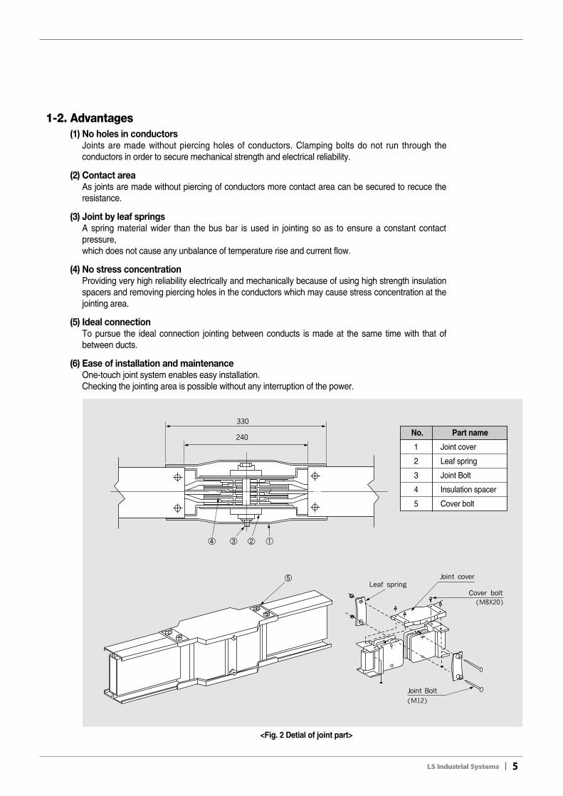
No. Part name
1 Joint cover
2 Leaf spring
3 Joint Bolt
4 Insulation spacer
5 Cover bolt
1-2. Advantages(1) No holes in conductors
Joints are made without piercing holes of conductors. Clamping bolts do not run through theconductors in order to secure mechanical strength and electrical reliability.
(2) Contact areaAs joints are made without piercing of conductors more contact area can be secured to recuce theresistance.
(3) Joint by leaf springsA spring material wider than the bus bar is used in jointing so as to ensure a constant contactpressure,which does not cause any unbalance of temperature rise and current flow.
(4) No stress concentrationProviding very high reliability electrically and mechanically because of using high strength insulationspacers and removing piercing holes in the conductors which may cause stress concentration at thejointing area.
(5) Ideal connectionTo pursue the ideal connection jointing between conducts is made at the same time with that ofbetween ducts.
(6) Ease of installation and maintenanceOne-touch joint system enables easy installation.Checking the jointing area is possible without any interruption of the power.
<Fig. 2 Detial of joint part>
6II
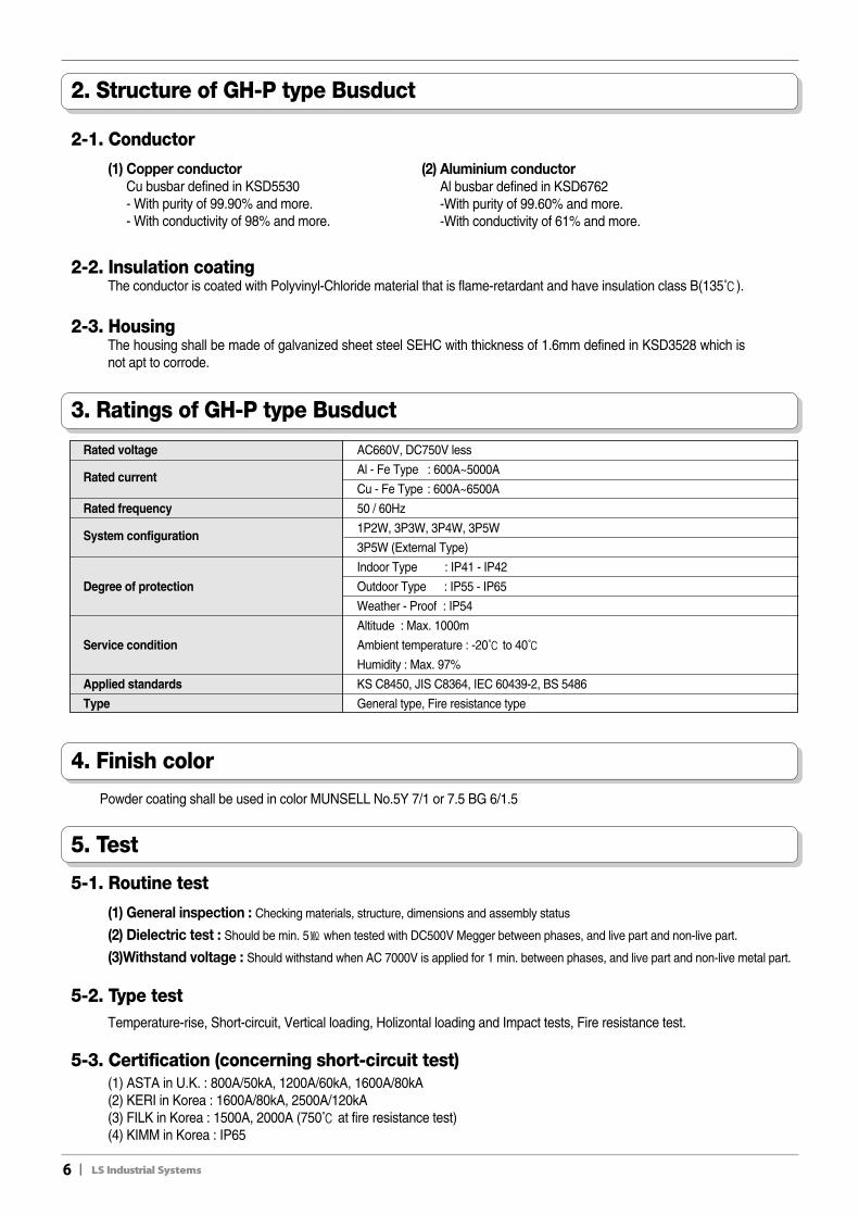
2. Structure of GH-P type Busduct
2-2. Insulation coatingThe conductor is coated with Polyvinyl-Chloride material that is flame-retardant and have insulation class B(135℃).
2-3. HousingThe housing shall be made of galvanized sheet steel SEHC with thickness of 1.6mm defined in KSD3528 which isnot apt to corrode.
2-1. Conductor
(1) Copper conductorCu busbar defined in KSD5530- With purity of 99.90% and more.- With conductivity of 98% and more.
(2) Aluminium conductorAl busbar defined in KSD6762-With purity of 99.60% and more.-With conductivity of 61% and more.
5. Test
5-1. Routine test
(1) General inspection : Checking materials, structure, dimensions and assembly status
(2) Dielectric test : Should be min. 5㏁ when tested with DC500V Megger between phases, and live part and non-live part.
(3)Withstand voltage : Should withstand when AC 7000V is applied for 1 min. between phases, and live part and non-live metal part.
5-2. Type testTemperature-rise, Short-circuit, Vertical loading, Holizontal loading and Impact tests, Fire resistance test.
5-3. Certification (concerning short-circuit test)(1) ASTA in U.K. : 800A/50kA, 1200A/60kA, 1600A/80kA(2) KERI in Korea : 1600A/80kA, 2500A/120kA(3) FILK in Korea : 1500A, 2000A (750℃ at fire resistance test)(4) KIMM in Korea : IP65
3. Ratings of GH-P type Busduct
Rated voltage AC660V, DC750V less
Rated currentAl - Fe Type : 600A~5000A
Cu - Fe Type : 600A~6500A
Rated frequency 50 / 60Hz
System configuration1P2W, 3P3W, 3P4W, 3P5W
3P5W (External Type)
Indoor Type : IP41 - IP42
Degree of protection Outdoor Type : IP55 - IP65
Weather - Proof : IP54
Altitude : Max. 1000m
Service condition Ambient temperature : -20℃ to 40℃
Humidity : Max. 97%
Applied standards KS C8450, JIS C8364, IEC 60439-2, BS 5486
Type General type, Fire resistance type
4. Finish color
Powder coating shall be used in color MUNSELL No.5Y 7/1 or 7.5 BG 6/1.5
II7
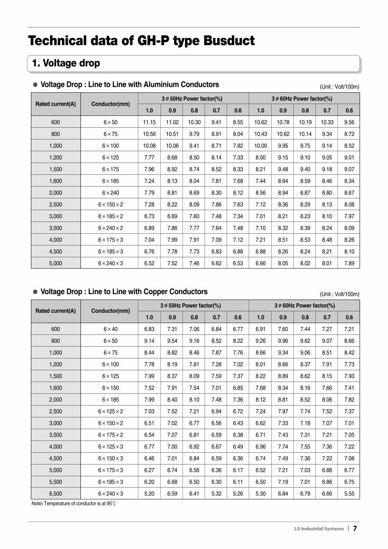
1. Voltage drop
Note) Temperature of conductor is at 95℃
Rated current(A) Conductor(mm)3∅∅50Hz Power factor(%) 3∅∅60Hz Power factor(%)
1.0 0.9 0.8 0.7 0.6 1.0 0.9 0.8 0.7 0.6
600 6×40 6.83 7.31 7.06 6.84 6.77 6.91 7.60 7.44 7.27 7.21
800 6×50 9.14 9.54 9.16 8.52 8.22 9.26 9.96 9.62 9.07 8.66
1,000 6×75 8.44 8.82 8.46 7.87 7.76 8.66 9.34 9.06 8.51 8.42
1,200 6×100 7.78 8.19 7.81 7.28 7.02 8.01 8.66 8.37 7.91 7.73
1,500 6×125 7.99 8.37 8.09 7.59 7.37 8.22 8.89 8.62 8.15 7.93
1,600 6×150 7.52 7.91 7.54 7.01 6.85 7.68 8.34 8.16 7.66 7.41
2,000 6×185 7.99 8.40 8.10 7.48 7.36 8.12 8.81 8.52 8.06 7.82
2,500 6×125×2 7.03 7.52 7.21 6.94 6.72 7.24 7.97 7.74 7.52 7.37
3,000 6×150×2 6.51 7.02 6.77 6.56 6.43 6.62 7.33 7.18 7.07 7.01
3,500 6×175×2 6.54 7.07 6.81 6.59 6.38 6.71 7.43 7.31 7.21 7.05
4,000 6×125×3 6.77 7.00 6.92 6.67 6.49 6.96 7.74 7.55 7.36 7.22
4,500 6×150×3 6.46 7.01 6.84 6.59 6.36 6.74 7.49 7.36 7.22 7.08
5,000 6×175×3 6.27 6.74 6.56 6.36 6.17 6.52 7.21 7.03 6.88 6.77
5,500 6×185×3 6.20 6.68 6.50 6.30 6.11 6.50 7.19 7.01 6.86 6.75
6,500 6×240×3 5.20 6.59 6.41 5.32 5.26 5.30 6.84 6.79 6.66 5.55
●● Voltage Drop : Line to Line with Copper Conductors
●● Voltage Drop : Line to Line with Aluminium Conductors (Unit : Volt/100m)
Rated current(A) Conductor(mm)3∅∅50Hz Power factor(%) 3∅∅60Hz Power factor(%)
1.0 0.9 0.8 0.7 0.6 1.0 0.9 0.8 0.7 0.6
600 6×50 11.15 11.02 10.30 9.41 8.55 10.62 10.78 10.19 10.33 9.56
800 6×75 10.56 10.51 9.79 8.91 8.04 10.43 10.62 10.14 9.34 8.72
1,000 6×100 10.08 10.06 9.41 8.71 7.82 10.00 9.95 9.75 9.14 8.52
1,200 6×125 7.77 8.68 8.50 8.14 7.33 8.00 9.15 9.10 9.05 9.01
1,500 6×175 7.96 8.92 8.74 8.52 8.33 8.21 9.48 9.40 9.18 9.07
1,600 6×185 7.24 8.13 8.04 7.81 7.68 7.44 8.64 8.59 8.46 8.34
2,000 6×240 7.79 8.81 8.69 8.30 8.12 8.56 8.94 8.87 8.80 8.67
2,500 6×150×2 7.28 8.22 8.09 7.86 7.63 7.12 8.36 8.29 8.13 8.08
3,000 6×185×2 6.73 6.69 7.60 7.48 7.34 7.01 8.21 8.23 8.10 7.97
3,500 6×240×2 6.89 7.86 7.77 7.64 7.48 7.10 8.32 8.39 8.24 8.09
4,000 6×175×3 7.04 7.99 7.91 7.09 7.12 7.21 8.51 8.53 8.48 8.26
4,500 6×185×3 6.76 7.78 7.73 6.83 6.88 6.88 8.26 8.24 8.21 8.10
5,000 6×240×3 6.52 7.52 7.46 6.62 6.53 6.66 8.05 8.02 8.01 7.89
Technical data of GH-P type Busduct
(Unit : Volt/100m)
8II
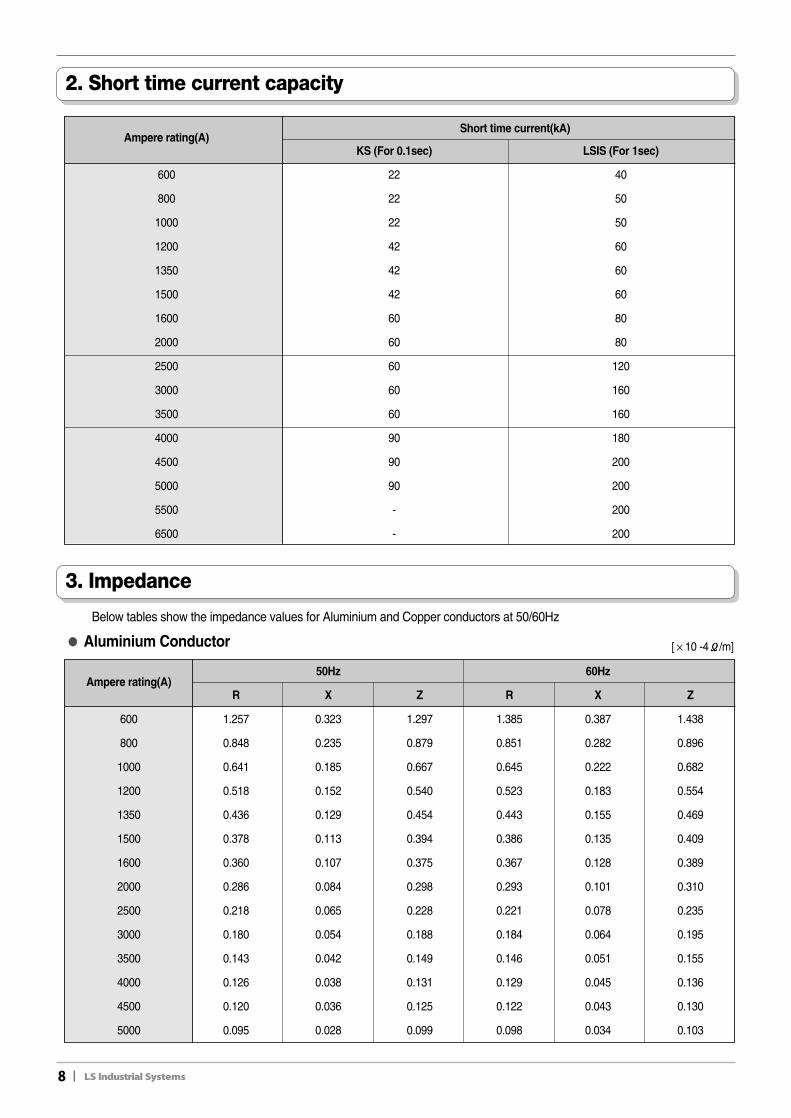
2. Short time current capacity
Ampere rating(A)Short time current(kA)
KS (For 0.1sec) LSIS (For 1sec)
600 22 40
800 22 50
1000 22 50
1200 42 60
1350 42 60
1500 42 60
1600 60 80
2000 60 80
2500 60 120
3000 60 160
3500 60 160
4000 90 180
4500 90 200
5000 90 200
5500 - 200
6500 - 200
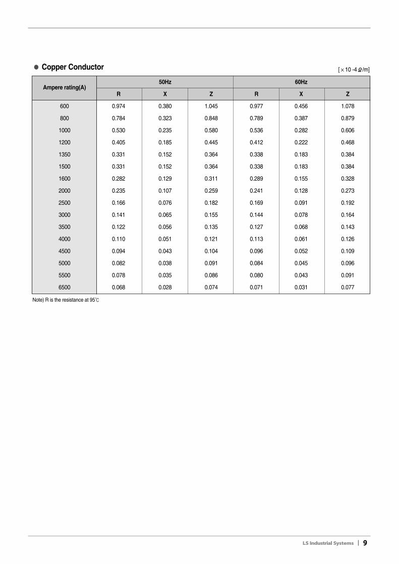
3. Impedance
Below tables show the impedance values for Aluminium and Copper conductors at 50/60Hz
Ampere rating(A)50Hz 60Hz
R X Z R X Z
600 1.257 0.323 1.297 1.385 0.387 1.438
800 0.848 0.235 0.879 0.851 0.282 0.896
1000 0.641 0.185 0.667 0.645 0.222 0.682
1200 0.518 0.152 0.540 0.523 0.183 0.554
1350 0.436 0.129 0.454 0.443 0.155 0.469
1500 0.378 0.113 0.394 0.386 0.135 0.409
1600 0.360 0.107 0.375 0.367 0.128 0.389
2000 0.286 0.084 0.298 0.293 0.101 0.310
2500 0.218 0.065 0.228 0.221 0.078 0.235
3000 0.180 0.054 0.188 0.184 0.064 0.195
3500 0.143 0.042 0.149 0.146 0.051 0.155
4000 0.126 0.038 0.131 0.129 0.045 0.136
4500 0.120 0.036 0.125 0.122 0.043 0.130
5000 0.095 0.028 0.099 0.098 0.034 0.103
●● Aluminium Conductor [×10 -4Ω/m]
II9
Ampere rating(A)50Hz 60Hz
R X Z R X Z
600 0.974 0.380 1.045 0.977 0.456 1.078
800 0.784 0.323 0.848 0.789 0.387 0.879
1000 0.530 0.235 0.580 0.536 0.282 0.606
1200 0.405 0.185 0.445 0.412 0.222 0.468
1350 0.331 0.152 0.364 0.338 0.183 0.384
1500 0.331 0.152 0.364 0.338 0.183 0.384
1600 0.282 0.129 0.311 0.289 0.155 0.328
2000 0.235 0.107 0.259 0.241 0.128 0.273
2500 0.166 0.076 0.182 0.169 0.091 0.192
3000 0.141 0.065 0.155 0.144 0.078 0.164
3500 0.122 0.056 0.135 0.127 0.068 0.143
4000 0.110 0.051 0.121 0.113 0.061 0.126
4500 0.094 0.043 0.104 0.096 0.052 0.109
5000 0.082 0.038 0.091 0.084 0.045 0.096
5500 0.078 0.035 0.086 0.080 0.043 0.091
6500 0.068 0.028 0.074 0.071 0.031 0.077
Note) R is the resistance at 95℃
●● Copper Conductor [×10 -4Ω/m]

4. Temperature characteristics
4-1. Temperature curve at rated current
(1) The allowable degree is 95℃℃ under the current.(2) Temperature rise is 55℃℃ at ambient temperature 40℃℃
10II
<Fig.1 Temperature checking points of the joint part>
●● 3∅∅3W 2000A (Example)
●● 3∅∅3W 1200A (Example)
①, ③ The joint part oftheoutside conductor
② The joint part of themiddle conductor
④ The insulation part of themiddle conductor
⑤ Surface of a housing
⑥ Ambient temperature

II11
4-2. Temperature rise at thermal current
Saturated temperature rise is 55℃ at any rated currents.
(1) Temperature rise at different load currents(2) Allowable load current to short time current before saturation(3) You can get the above values from below curves.
1. Allowable temperature rise is 32℃ when 1650A flows in 2000 rating busduct.2. Allowable overload current is 5300A/hr at no load status in 3500 rating busduct.
Ambient temperatureFactor
Ambient temperatureFactor
℃℃ ��F ℃℃ ��F
15 59 1.21 40 104 1.00
20 68 1.17 45 113 0.95
25 77 1.13 50 122 0.90
30 86 1.09 55 131 0.85
35 95 1.04 60 140 0.80
Factor for allowable current by ambient temperature
<Fig.2 Temperature rise curves at thermal current>
Example
12II
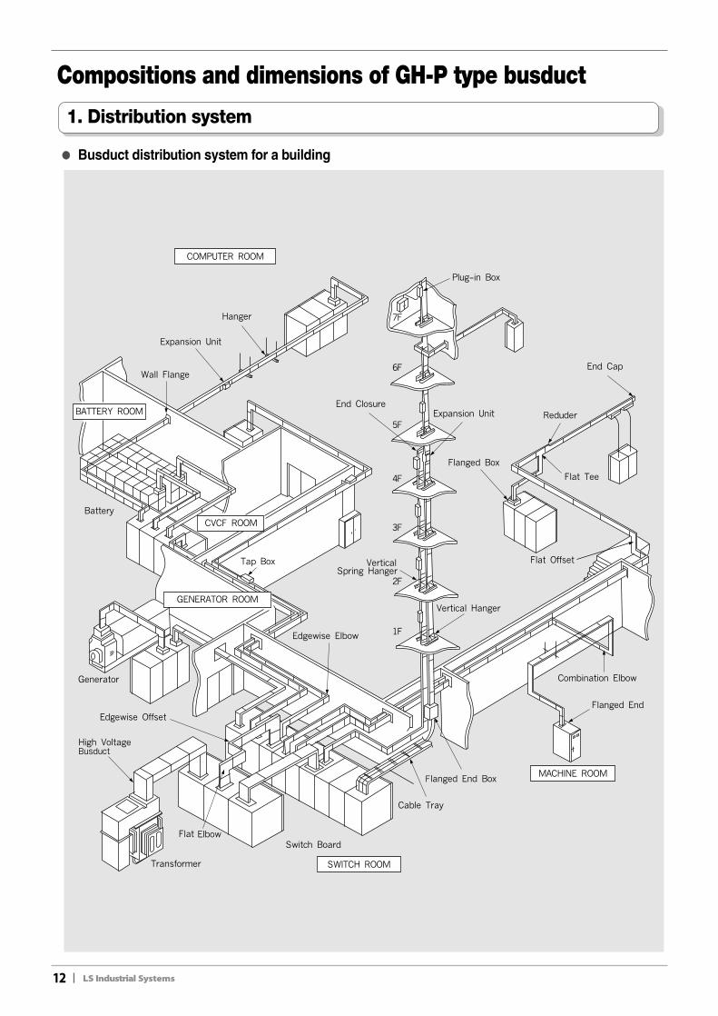
Compositions and dimensions of GH-P type busduct
1. Distribution system
●● Busduct distribution system for a building
II13
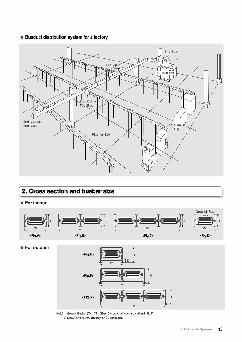
●● Busduct distribution system for a factory
●● For indoor
●● For outdoor
2. Cross section and busbar size
Note) 1. Ground Busbar (Cu : 3T×25mm) is external type and optional. Fig.D2. 5500A and 6500A are only for Cu conductor.
<Fig.A>
<Fig.E>
<Fig.F>
<Fig.G>
<Fig.B> <Fig.C> <Fig.D>
14II
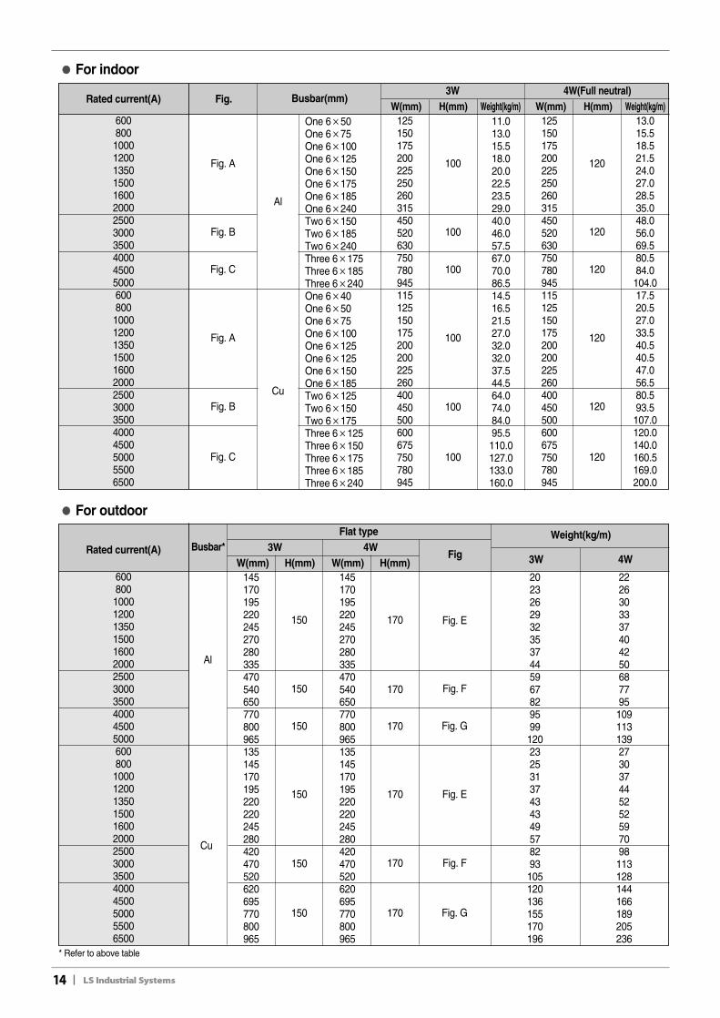
●● For indoor
* Refer to above table
Rated current(A)
60080010001200135015001600200025003000350040004500500060080010001200135015001600200025003000350040004500500055006500
Fig. Busbar(mm)3W
W(mm) H(mm) Weight(kg/m)4W(Full neutral)
W(mm) H(mm) Weight(kg/m)
Al
Cu
Fig. A
Fig. B
Fig. C
Fig. A
Fig. B
Fig. C
One 6×50One 6×75One 6×100One 6×125One 6×150One 6×175One 6×185One 6×240Two 6×150Two 6×185Two 6×240Three 6×175Three 6×185Three 6×240One 6×40One 6×50One 6×75One 6×100One 6×125One 6×125One 6×150One 6×185Two 6×125Two 6×150Two 6×175Three 6×125Three 6×150Three 6×175Three 6×185Three 6×240
125150175200225250260315450520630750780945115125150175200200225260400450500600675750780945
100 120
100 120
100 120
100 120
100 120
100 120
11.013.015.518.020.022.523.529.040.046.057.567.070.086.514.516.521.527.032.032.037.544.564.074.084.095.5110.0127.0133.0160.0
13.015.518.521.524.027.028.535.048.056.069.580.584.0104.017.520.527.033.540.540.547.056.580.593.5107.0120.0140.0160.5169.0200.0
125150175200225250260315450520630750780945115125150175200200225260400450500600675750780945
●● For outdoor
Rated current(A)
60080010001200135015001600200025003000350040004500500060080010001200135015001600200025003000350040004500500055006500
Busbar*Flat type
3WW(mm) H(mm)
4WW(mm) H(mm)
Fig
Al
Cu
Fig. E
Fig. F
Fig. G
Fig. E
Fig. F
Fig. G
145170195220245270280335470540650770800965135145170195220220245280420470520620695770800965
150 170
150 170
150 170
150 170
150 170
150 170
2023262932353744596782959912023253137434349578293105120136155170196
2226303337404250687795109113139273037445252597098113128144166189205236
145170195220245270280335470540650770800965135145170195220220245280420470520620695770800965
Weight(kg/m)
3W 4W
II15
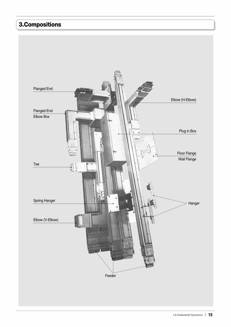
3.Compositions
Flanged End
Elbow (H-Elbow)
Floor Flange
Wall Flange
Hanger
Plug in Box
Spring Hanger
Tee
Elbow (V-Elbow)
Feeder
Flanged End
Elbow Box
16II
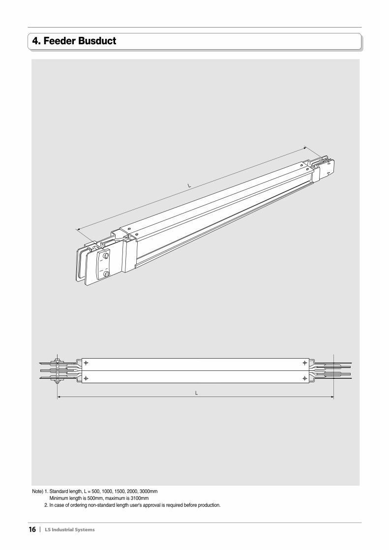
4. Feeder Busduct
Note) 1. Standard length, L = 500, 1000, 1500, 2000, 3000mmMinimum length is 500mm, maximum is 3100mm
2. In case of ordering non-standard length user's approval is required before production.
II17
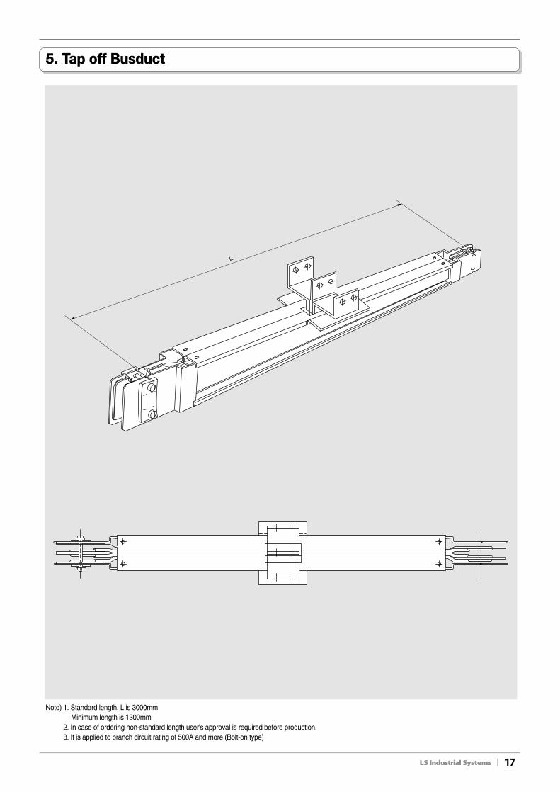
5. Tap off Busduct
Note) 1. Standard length, L is 3000mmMinimum length is 1300mm
2. In case of ordering non-standard length user's approval is required before production.3. It is applied to branch circuit rating of 500A and more (Bolt-on type)
18II
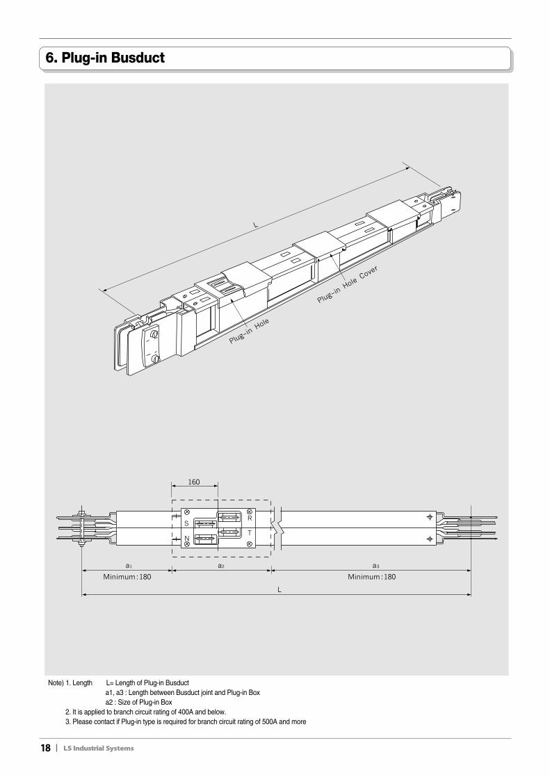
6. Plug-in Busduct
Note) 1. Length L= Length of Plug-in Busducta1, a3 : Length between Busduct joint and Plug-in Boxa2 : Size of Plug-in Box
2. It is applied to branch circuit rating of 400A and below.3. Please contact if Plug-in type is required for branch circuit rating of 500A and more
II19
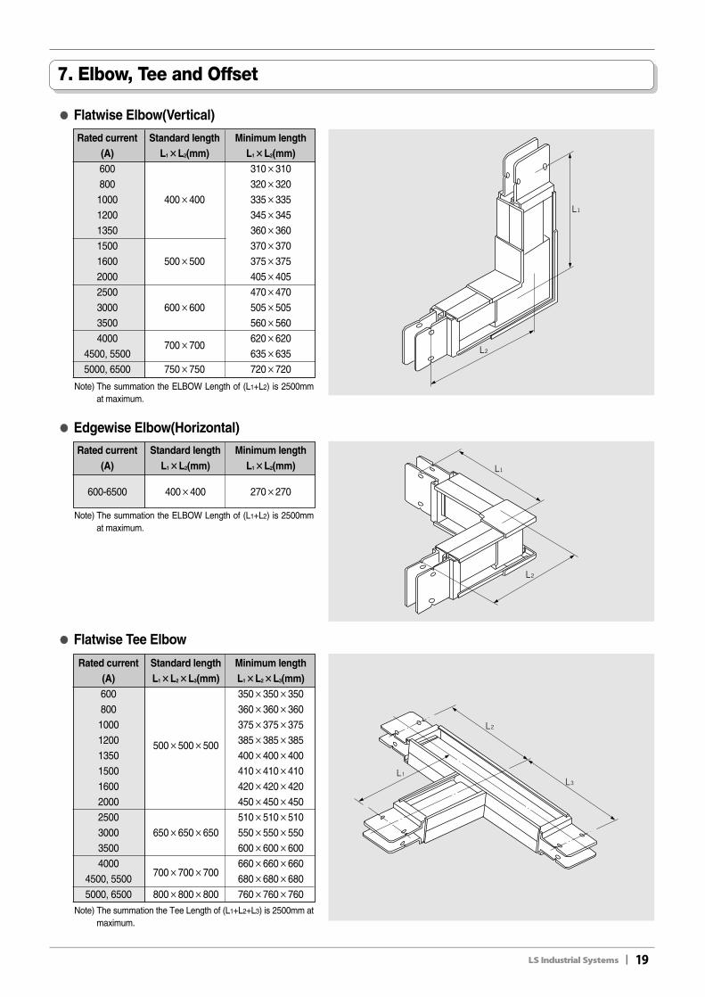
7. Elbow, Tee and Offset
●● Flatwise Elbow(Vertical)
Rated current Standard length Minimum length(A) L1××L2(mm) L1××L2(mm)600 310×310800 320×3201000 400×400 335×3351200 345×3451350 360×3601500 370×3701600 500×500 375×3752000 405×4052500 470×4703000 600×600 505×5053500 560×5604000 620×620
4500, 5500700×700
635×6355000, 6500 750×750 720×720
Note) The summation the ELBOW Length of (L1+L2) is 2500mmat maximum.
●● Flatwise Tee Elbow
Rated current Standard length Minimum length(A) L1××L2××L3(mm) L1××L2××L3(mm)600 350×350×350800 360×360×3601000 375×375×3751200 500×500×500 385×385×3851350 400×400×4001500 410×410×4101600 420×420×4202000 450×450×4502500 510×510×5103000 650×650×650 550×550×5503500 600×600×6004000 660×660×660
4500, 5500 700×700×700
680×680×6805000, 6500 800×800×800 760×760×760
Note) The summation the Tee Length of (L1+L2+L3) is 2500mm atmaximum.
●● Edgewise Elbow(Horizontal)
Rated current Standard length Minimum length(A) L1××L2(mm) L1××L2(mm)
600-6500 400×400 270×270
Note) The summation the ELBOW Length of (L1+L2) is 2500mmat maximum.
20II
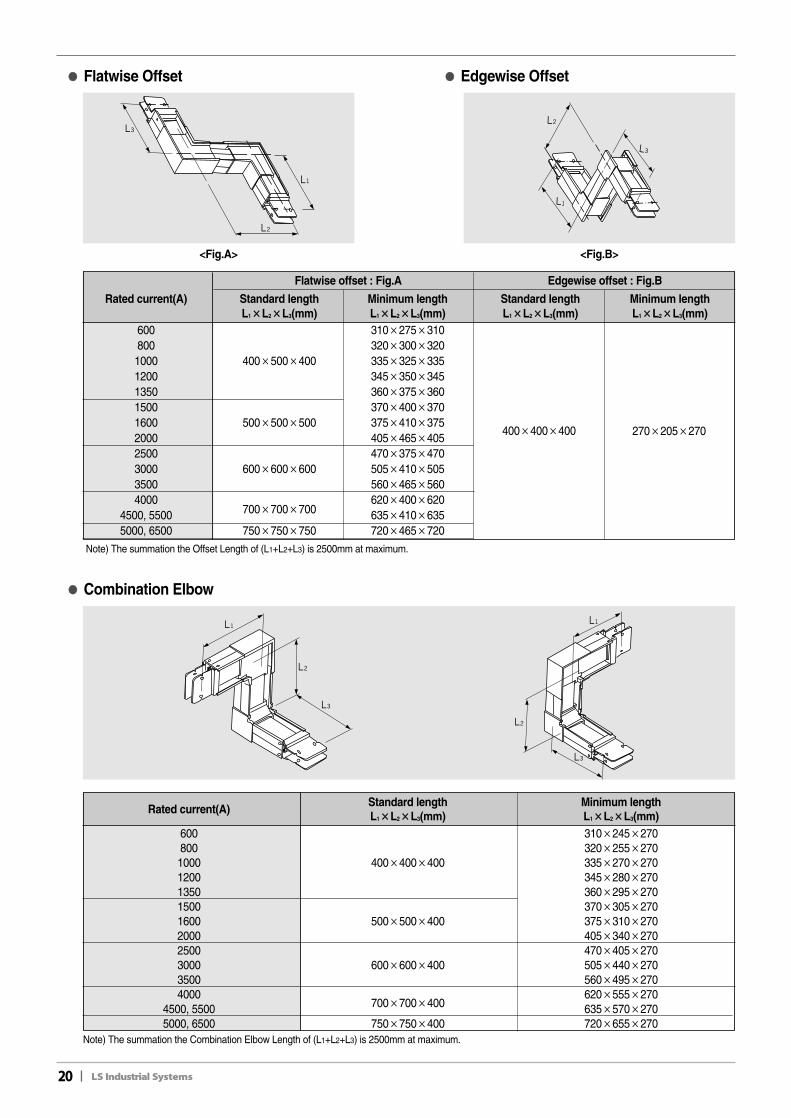
●● Edgewise Offset
<Fig.A>
●● Flatwise Offset
<Fig.B>
Flatwise offset : Fig.A
Rated current(A) Standard length Minimum lengthL1××L2××L3(mm) L1××L2××L3(mm)
600 310×275×310800 320×300×3201000 400×500×400 335×325×3351200 345×350×3451350 360×375×3601500 370×400×3701600 500×500×500 375×410×3752000 405×465×4052500 470×375×4703000 600×600×600 505×410×5053500 560×465×5604000 620×400×620
4500, 5500 700×700×700 635×410×6355000, 6500 750×750×750 720×465×720
Note) The summation the Offset Length of (L1+L2+L3) is 2500mm at maximum.
Edgewise offset : Fig.B
Standard length Minimum lengthL1××L2××L3(mm) L1××L2××L3(mm)
400×400×400 270×205×270
●● Combination Elbow
Rated current(A)Standard length Minimum lengthL1××L2××L3(mm) L1××L2××L3(mm)
600 310×245×270800 320×255×2701000 400×400×400 335×270×2701200 345×280×2701350 360×295×2701500 370×305×2701600 500×500×400 375×310×2702000 405×340×2702500 470×405×2703000 600×600×400 505×440×2703500 560×495×2704000 620×555×270
4500, 5500 700×700×400 635×570×2705000, 6500 750×750×400 720×655×270
Note) The summation the Combination Elbow Length of (L1+L2+L3) is 2500mm at maximum.
II21
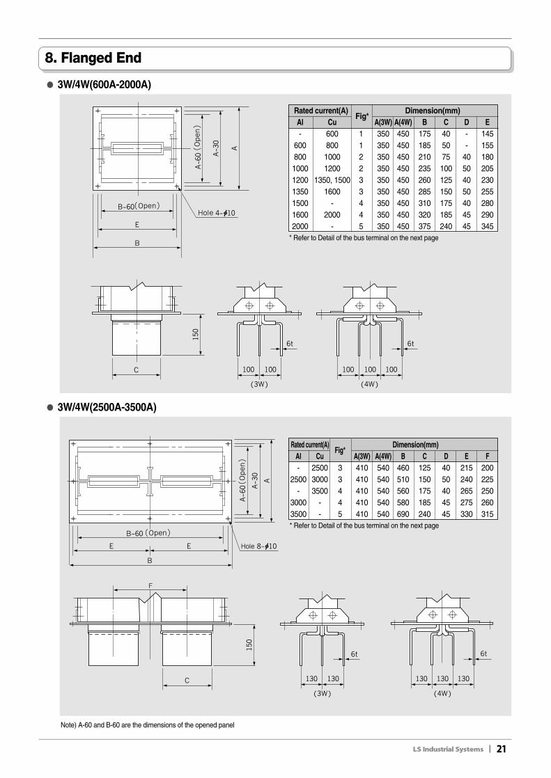
8. Flanged End
●● 3W/4W(600A-2000A)
Note) A-60 and B-60 are the dimensions of the opened panel
* Refer to Detail of the bus terminal on the next page
Rated current(A)Fig*
Dimension(mm)Al Cu A(3W) A(4W) B C D E- 600 1 350 450 175 40 - 145
600 800 1 350 450 185 50 - 155800 1000 2 350 450 210 75 40 1801000 1200 2 350 450 235 100 50 2051200 1350, 1500 3 350 450 260 125 40 2301350 1600 3 350 450 285 150 50 2551500 - 4 350 450 310 175 40 2801600 2000 4 350 450 320 185 45 2902000 - 5 350 450 375 240 45 345
●● 3W/4W(2500A-3500A)
* Refer to Detail of the bus terminal on the next page
Rated current(A)Fig*
Dimension(mm)Al Cu A(3W) A(4W) B C D E F- 2500 3 410 540 460 125 40 215 200
2500 3000 3 410 540 510 150 50 240 225- 3500 4 410 540 560 175 40 265 250
3000 - 4 410 540 580 185 45 275 2603500 - 5 410 540 690 240 45 330 315
22II
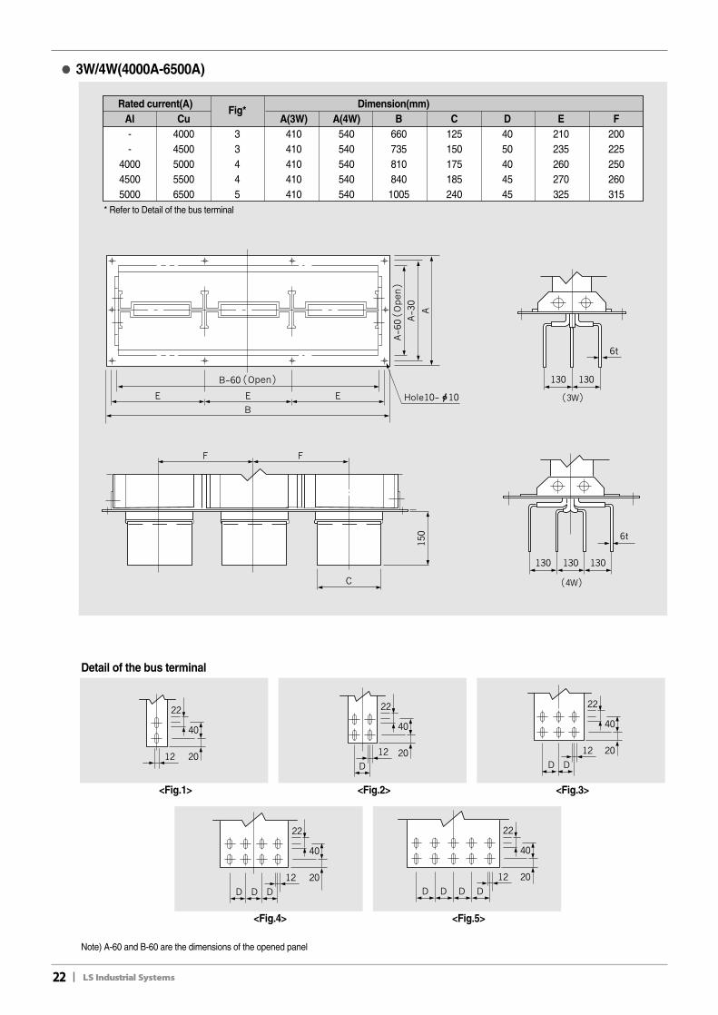
●● 3W/4W(4000A-6500A)
Rated current(A)Fig*
Dimension(mm)Al Cu A(3W) A(4W) B C D E F- 4000 3 410 540 660 125 40 210 200- 4500 3 410 540 735 150 50 235 225
4000 5000 4 410 540 810 175 40 260 2504500 5500 4 410 540 840 185 45 270 2605000 6500 5 410 540 1005 240 45 325 315
Detail of the bus terminal
<Fig.1> <Fig.2>
<Fig.4> <Fig.5>
<Fig.3>
* Refer to Detail of the bus terminal
Note) A-60 and B-60 are the dimensions of the opened panel
II23
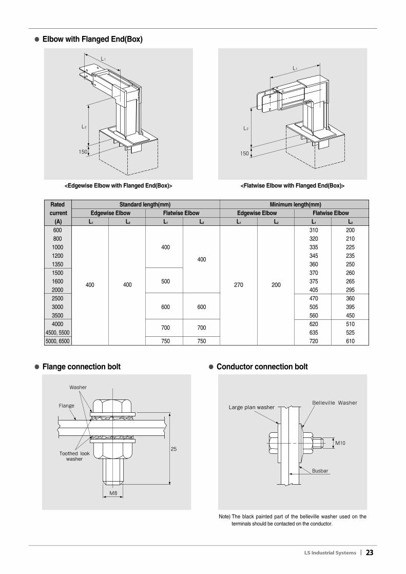
●● Elbow with Flanged End(Box)
<Edgewise Elbow with Flanged End(Box)> <Flatwise Elbow with Flanged End(Box)>
●● Flange connection bolt ●● Conductor connection bolt
Note) The black painted part of the belleville washer used on theterminals should be contacted on the conductor.
Rated Standard length(mm) Minimum length(mm)current Edgewise Elbow Flatwise Elbow Edgewise Elbow Flatwise Elbow
(A) L1 L2 L1 L2 L1 L2 L1 L2
600 310 200800 320 2101000 400 335 2251200
400345 235
1350 360 2501500 370 2601600 500 375 2652000 405 2952500 470 3603000 600 600 505 3953500 560 4504000
700 700620 510
4500, 5500 635 5255000, 6500 750 750 720 610
400 400 270 200
24II
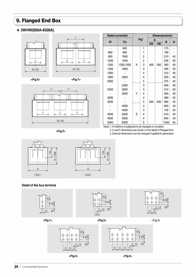
9. Flanged End Box
●● 3W/4W(600A-6500A)
Note) 1. H=450mm is subjected to be changed on condition.2. C and F dimensions are shown on the detail of Flanged End.3. External dimensions can be changed if applied to generators
Rated current(A) Dimension(mm)
Al CuFig* A
B D3W 4W
- 600 1 175 -600 800 1 185 -800 1000 2 210 401000 1200 2 235 501200 1350,1500 X 3 400 500 260 401350 1600 3 285 501500 - 4 310 401600 2000 4 320 452000 - 5 375 45
- 2500 3 460 402500 3000 3 510 50
- 3500 Y 4 560 403000 - 4 580 453500 - 5 500 630 690 45
- 4000 3 660 40- 4500 3 735 50
4000 5000 Z 4 810 404500 5500 4 840 455000 6500 5 1005 45
Detail of the bus terminal
<Fig.X>
<Fig.Z>
<Fig.Y>
<Fig.1> <Fig.2>
<Fig.4> <Fig.5>
<Fig.3>
II25
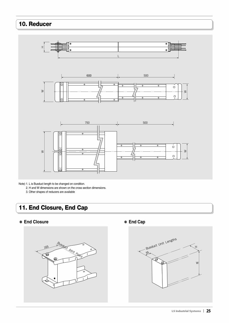
10. Reducer
11. End Closure, End Cap
Note) 1. L is Busduct length to be changed on condition.2. H and W dimensions are shown on the cross section dimensions.3. Other shapes of reducers are available
●● End Closure ●● End Cap
26II
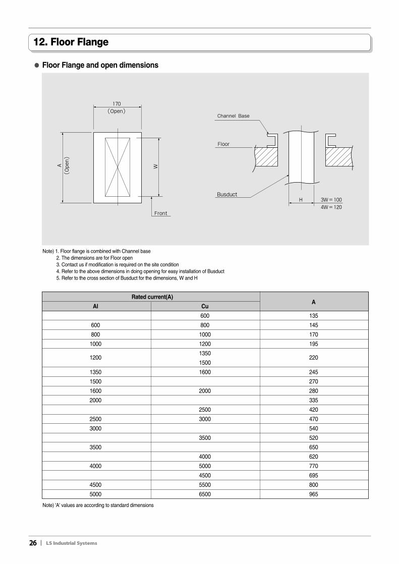
12. Floor Flange
●● Floor Flange and open dimensions
Note) 'A' values are according to standard dimensions
Rated current(A)
Al CuA
600 135
600 800 145
800 1000 170
1000 1200 195
12001350
2201500
1350 1600 245
1500 270
1600 2000 280
2000 335
2500 420
2500 3000 470
3000 540
3500 520
3500 650
4000 620
4000 5000 770
4500 695
4500 5500 800
5000 6500 965
Note) 1. Floor flange is combined with Channel base2. The dimensions are for Floor open3. Contact us if modification is required on the site condition 4. Refer to the above dimensions in doing opening for easy installation of Busduct5. Refer to the cross section of Busduct for the dimensions, W and H
II27
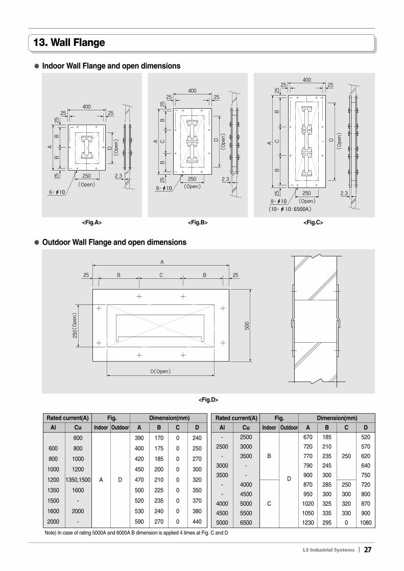
13. Wall Flange
●● Indoor Wall Flange and open dimensions
●● Outdoor Wall Flange and open dimensions
Rated current(A) Fig. Dimension(mm)
Al Cu Indoor Outdoor A B C D
- 2500 670 185 520
2500 3000 720 210 570
- 3500 B 770 235 250 620
3000 - 790 245 640
3500 -D
900 300 750
- 4000 870 285 250 720
- 4500 950 300 300 800
4000 5000 C 1020 325 320 870
4500 5500 1050 335 330 900
5000 6500 1230 295 0 1080
Rated current(A) Fig. Dimension(mm)
Al Cu Indoor Outdoor A B C D
600 390 170 0 240
600 800 400 175 0 250
800 1000 420 185 0 270
1000 1200 450 200 0 300
1200 1350,1500 A D 470 210 0 320
1350 1600 500 225 0 350
1500 - 520 235 0 370
1600 2000 530 240 0 380
2000 - 590 270 0 440
<Fig.A>
<Fig.D>
<Fig.B> <Fig.C>
Note) In case of rating 5000A and 6000A B dimension is applied 4 times at Fig. C and D
28II
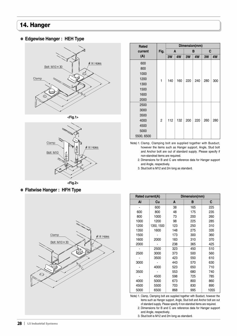
14. Hanger
●● Edgewise Hanger : HEH Type
●● Flatwise Hanger : HFH Type
Note) 1. Clamp, Clamping bolt are supplied together with Busduct,however the items such as Hanger support, Angle, Stud boltand Anchor bolt are out of standard supply. Please specify ifnon-standrad items are required.
2. Dimensions for B and C are reference data for Hanger supportand Angle, respectively.
3. Stud bolt is M12 and 2m long as standard.
Rated Dimension(mm)
current Fig. A B C(A) 3W 4W 3W 4W 3W 4W
600800100012001300150016002000250030003500400045005000
5500, 6500
1401 160 220 240 280
2 112 132 200 220 260 280
300
Rated current(A) Dimension(mm)
Al Cu A B C
-600800100012001350150016002000
-2500
-3000
-3500
-400045005000
60080010001200
1350, 15001600
-2000
-250030003500
-4000
-4500500055006500
38487398123148173183238323373423443523553598673703868
165175200225250275300310365450500550570650680725800830995
2252352602853103353603704255105606106307107407858608901055
<Fig.1>
<Fig.2>
Note) 1. Clamp, Clamping bolt are supplied together with Busduct, however theitems such as Hanger support, Angle, Stud bolt and Anchor bolt are outof standard supply. Please specify if non-standrad items are required.
2. Dimensions for B and C are reference data for Hanger supportand Angle, respectively.
3. Stud bolt is M12 and 2m long as standard.
II29
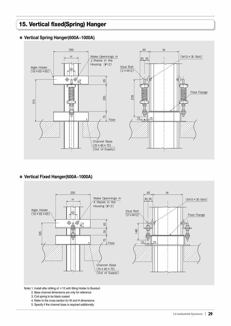
15. Vertical fixed(Spring) Hanger
●● Vertical Spring Hanger(600A~1000A)
●● Vertical Fixed Hanger(600A~1000A)
Note) 1. Install after drilling of ∅12 with fitting Holder to Busduct2. Base channel dimensions are only for reference3. Coil spring to be black coated4. Refer to the cross section for W and H dimensions5. Specify if the channel base is required additionally
30II
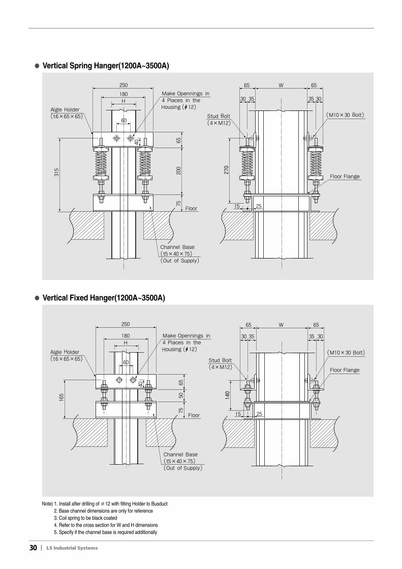
●● Vertical Spring Hanger(1200A~3500A)
●● Vertical Fixed Hanger(1200A~3500A)
Note) 1. Install after drilling of ∅12 with fitting Holder to Busduct2. Base channel dimensions are only for reference3. Coil spring to be black coated4. Refer to the cross section for W and H dimensions5. Specify if the channel base is required additionally
II31
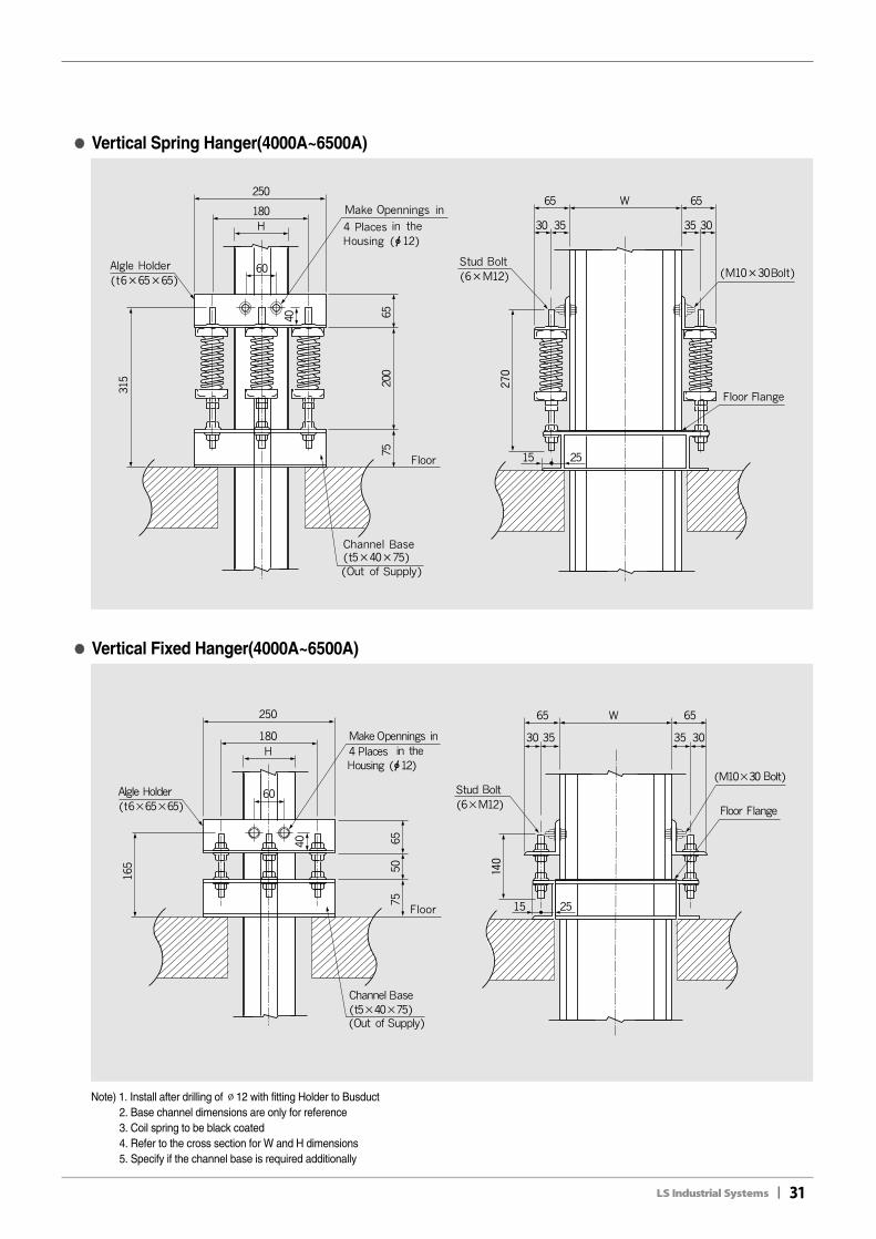
●● Vertical Spring Hanger(4000A~6500A)
●● Vertical Fixed Hanger(4000A~6500A)
Note) 1. Install after drilling of ∅12 with fitting Holder to Busduct2. Base channel dimensions are only for reference3. Coil spring to be black coated4. Refer to the cross section for W and H dimensions5. Specify if the channel base is required additionally
32II
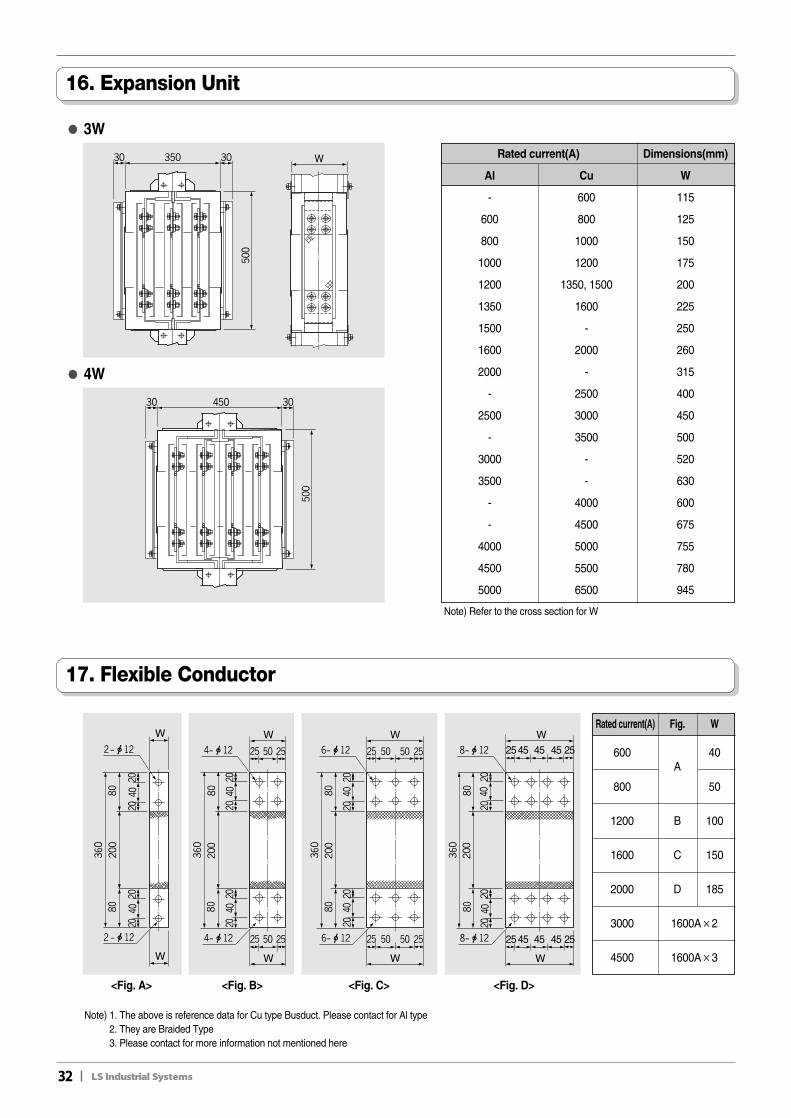
16. Expansion Unit
17. Flexible Conductor
●● 3W
●● 4W
Note) 1. The above is reference data for Cu type Busduct. Please contact for Al type2. They are Braided Type3. Please contact for more information not mentioned here
Note) Refer to the cross section for W
Rated current(A) Dimensions(mm)
Al Cu W
- 600 115
600 800 125
800 1000 150
1000 1200 175
1200 1350, 1500 200
1350 1600 225
1500 - 250
1600 2000 260
2000 - 315
- 2500 400
2500 3000 450
- 3500 500
3000 - 520
3500 - 630
- 4000 600
- 4500 675
4000 5000 755
4500 5500 780
5000 6500 945
Rated current(A) Fig. W
600A
40
800 50
1200 B 100
1600 C 150
2000 D 185
3000 1600A×2
4500 1600A×3
<Fig. A> <Fig. B> <Fig. C> <Fig. D>
II33
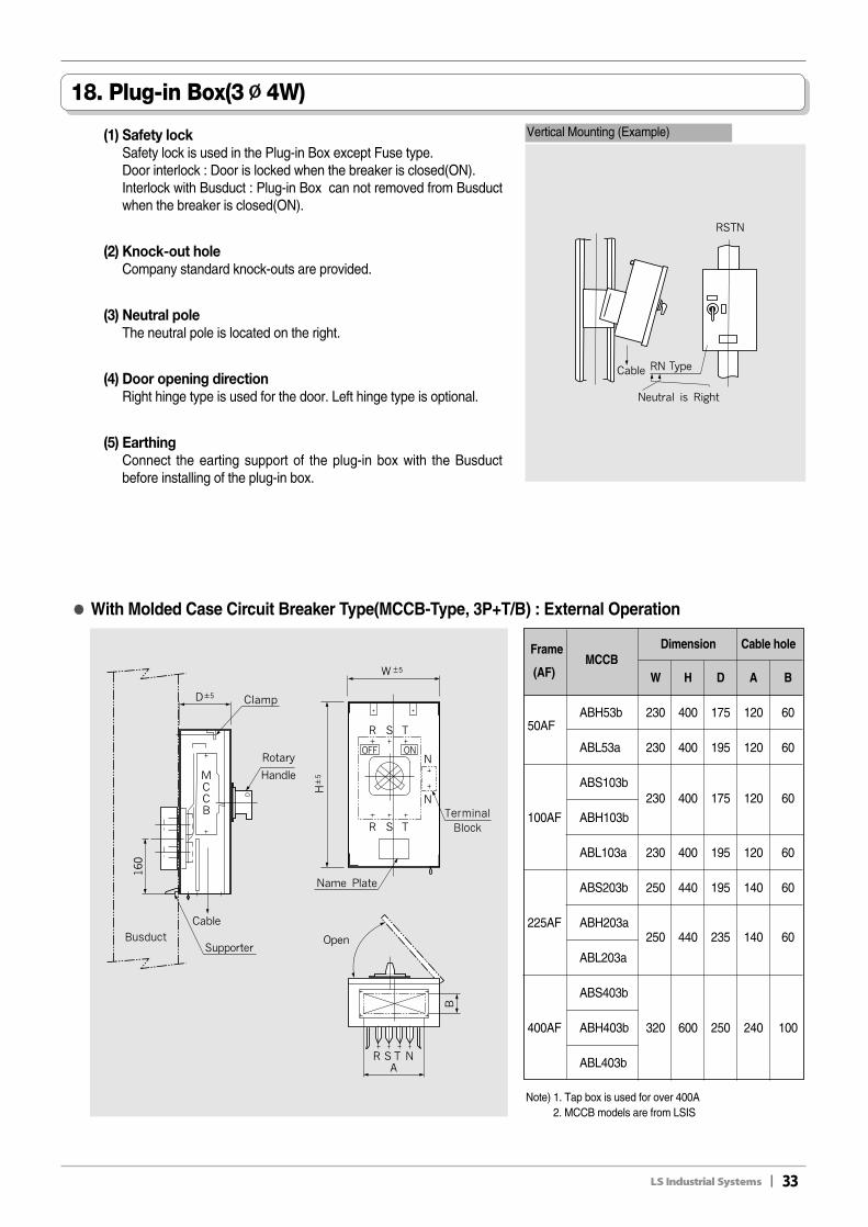
18. Plug-in Box(3∅∅4W)
(1) Safety lockSafety lock is used in the Plug-in Box except Fuse type.Door interlock : Door is locked when the breaker is closed(ON).Interlock with Busduct : Plug-in Box can not removed from Busductwhen the breaker is closed(ON).
(2) Knock-out holeCompany standard knock-outs are provided.
(3) Neutral poleThe neutral pole is located on the right.
(4) Door opening directionRight hinge type is used for the door. Left hinge type is optional.
(5) EarthingConnect the earting support of the plug-in box with the Busductbefore installing of the plug-in box.
●● With Molded Case Circuit Breaker Type(MCCB-Type, 3P+T/B) : External Operation
Note) 1. Tap box is used for over 400A2. MCCB models are from LSIS
Vertical Mounting (Example)
FrameMCCB
Dimension Cable hole
(AF) W H D A B
50AFABH53b 230 400 175 120 60
ABL53a 230 400 195 120 60
ABS103b230 400 175 120 60
100AF ABH103b
ABL103a 230 400 195 120 60
ABS203b 250 440 195 140 60
225AF ABH203a250 440 235 140 60
ABL203a
ABS403b
400AF ABH403b 320 600 250 240 100
ABL403b
34II
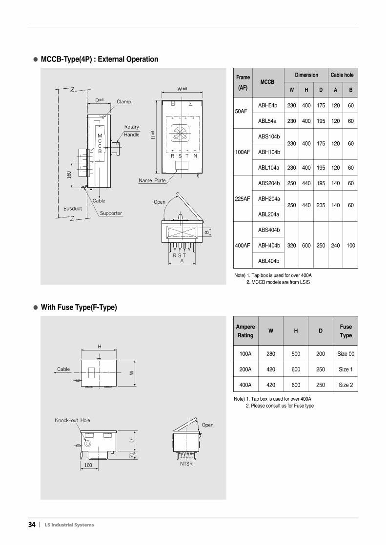
●● With Fuse Type(F-Type)
Note) 1. Tap box is used for over 400A2. Please consult us for Fuse type
Note) 1. Tap box is used for over 400A2. MCCB models are from LSIS
●● MCCB-Type(4P) : External Operation
FrameMCCB
Dimension Cable hole
(AF) W H D A B
50AFABH54b 230 400 175 120 60
ABL54a 230 400 195 120 60
ABS104b230 400 175 120 60
100AF ABH104b
ABL104a 230 400 195 120 60
ABS204b 250 440 195 140 60
225AF ABH204a250 440 235 140 60
ABL204a
ABS404b
400AF ABH404b 320 600 250 240 100
ABL404b
AmpereW H D
FuseRating Type
100A 280 500 200 Size 00
200A 420 600 250 Size 1
400A 420 600 250 Size 2
II35
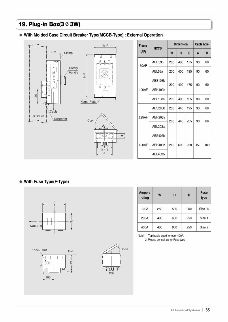
19. Plug-in Box(3∅∅3W)
●● With Molded Case Circuit Breaker Type(MCCB-Type) : External Operation
FrameMCCB
Dimension Cable hole
(AF) W H D A B
50AFABH53b 200 400 175 90 60
ABL53a 200 400 195 90 60
ABS103b200 400 175 90 60
100AF ABH103b
ABL103a 200 400 195 90 60
ABS203b 200 440 195 90 60
225AF ABH203a200 440 235 90 60
ABL203a
ABS403b
400AF ABH403b 240 600 250 150 100
ABL403b
●● With Fuse Type(F-Type)
Note) 1. Tap box is used for over 400A2. Please consult us for Fuse type
AmpereW H D
Fuserating type
100A 250 500 200 Size 00
200A 400 600 250 Size 1
400A 400 600 250 Size 2
36II
Busduct
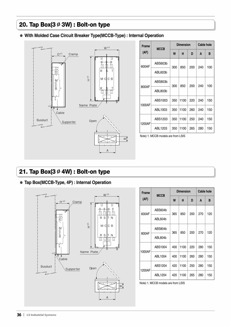
20. Tap Box(3∅∅3W) : Bolt-on type
21. Tap Box(3∅∅4W) : Bolt-on type
Note) 1. MCCB models are from LSIS
●● With Molded Case Circuit Breaker Type(MCCB-Type) : Internal Operation
FrameMCCB
Dimension Cable hole
(AF) W H D A B
600AFABS603b
300 850 200 240 100
ABL603b
ABS803b300 850 200 240 100800AF
ABL803b
1000AFABS1003 350 1100 220 240 150
ABL1003 350 1100 260 240 150
1200AFABS1203 350 1100 250 240 150
ABL1203 350 1100 265 280 150
Note) 1. MCCB models are from LSIS
FrameMCCB
Dimension Cable hole
(AF) W H D A B
600AFABS604b
365 850 200 270 120
ABL604b
ABS804b365 850 200 270 120800AF
ABL804b
1000AFABS1004 400 1100 220 280 150
ABL1004 400 1100 260 280 150
1200AFABS1204 420 1100 250 280 150
ABL1204 420 1100 265 280 150
●● Tap Box(MCCB-Type, 4P) : Internal Operation
II37
Busduct system design manual
1. Considerations in layout design
● The current and future loads should be condered in rated current of the busduct ● If the ambient temperature exceeds 40℃, the rated current needs to be compensated. (See the reference table)● Voltage drop should be considered if the long busducts are used.● Consider the mechanically thermal strength of the busduct concerning short-circuit current.● Lower rating Busduct can be used if Reducer is properly used in the Busduct Route.● Plug-in box is recommended for the connection of the load side and spare plug-in hole for future load should be
considered.● Straight arrangement is recommendable. Try not to use Elbow if possible.● Install it in the place that is dry and easy for maintenance.● Consulting with maker is recommendable for install route.● Remember it is tough to modify and change the spec during Busduct produing and installation.
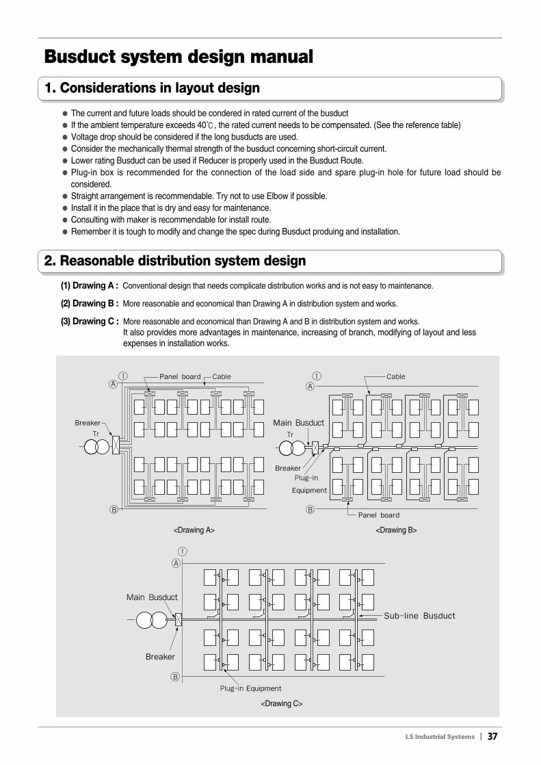
2. Reasonable distribution system design
<Drawing A>
<Drawing C>
<Drawing B>
(1) Drawing A : Conventional design that needs complicate distribution works and is not easy to maintenance.
(2) Drawing B : More reasonable and economical than Drawing A in distribution system and works.
(3) Drawing C : More reasonable and economical than Drawing A and B in distribution system and works.It also provides more advantages in maintenance, increasing of branch, modifying of layout and lessexpenses in installation works.
38II
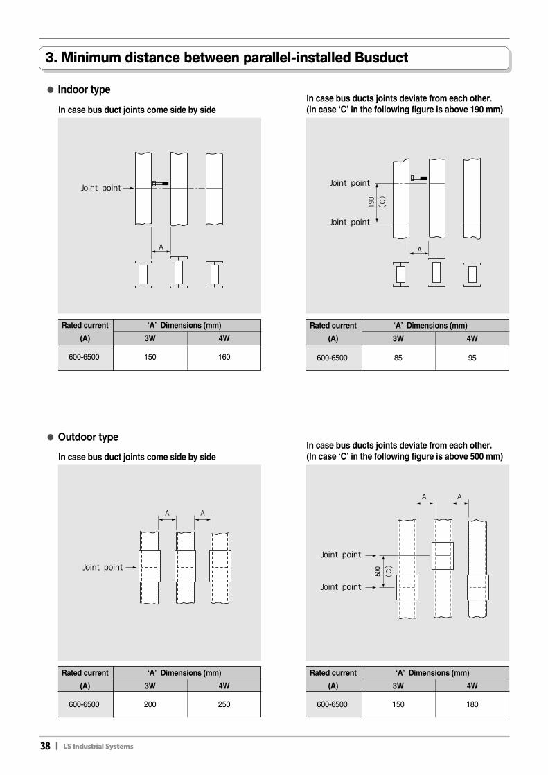
3. Minimum distance between parallel-installed Busduct
●● Indoor type
In case bus duct joints come side by side
Rated current ‘A’ Dimensions (mm)
(A) 3W 4W
600-6500 150 160
In case bus ducts joints deviate from each other.(In case ‘C’ in the following figure is above 190 mm)
Rated current ‘A’ Dimensions (mm)
(A) 3W 4W
600-6500 85 95
●● Outdoor type
In case bus duct joints come side by side
Rated current ‘A’ Dimensions (mm)
(A) 3W 4W
600-6500 200 250
In case bus ducts joints deviate from each other.(In case ‘C’ in the following figure is above 500 mm)
Rated current ‘A’ Dimensions (mm)
(A) 3W 4W
600-6500 150 180
II39
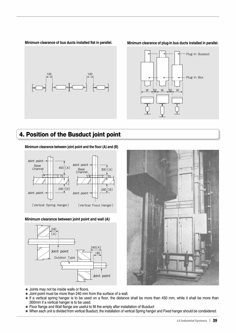
Minimum clearance of bus ducts installed flat in parallel. Minimum clearance of plug-in bus ducts installed in parallel.
Minimum clearance between joint point and the floor (A) and (B)
Minimum clearance between joint point and wall (A)
● Joints may not be inside walls or floors.● Joint point must be more than 240 mm from the surface of a wall.● If a vertical spring hanger is to be used on a floor, the distance shall be more than 450 mm, while it shall be more than
300mm if a vertical hanger is to be used.● Floor flange and Wall flange are useful to fill the empty after installation of Busduct● When each unit is divided from vertical Busduct, the installation of vertical Spring hanger and Fixed hanger should be condsidered.
4. Position of the Busduct joint point
40II
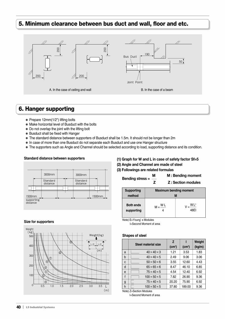
Bending stress =M M : Bending moment
Z Z : Section modules
● Prepare 12mm(1/2") lifting bolts● Make horizontal level of Busduct with the bolts● Do not overlap the joint with the lifting bolt● Busduct shall be fixed with Hanger● The standard distance between supporters of Busduct shall be 1.5m. It should not be longer than 2m● In case of more than one Busduct do not separate each Busduct and use one Hanger structure● The supporters such as Angle and Channel should be selected according to load, supporting distance and its condition.
Note) E=Young’s ModulesI=Second Moment of area
Note) Z=Section ModulesI=Second Moment of area
5. Minimum clearance between bus duct and wall, floor and etc.
6. Hanger supporting
Standarddistance
Standarddistance
supportingdistance
Standard distance between supporters
Size for supporters
Supporting Maximum bending moment
method M
M =W L
4
Both ends
supportingV =
W L3
48EI
Steel material sizeZ I Weight
(cm3) (cm3) (kg/m)
a 40×40×3 1.21 3.53 1.83b 40×40×5 2.49 9.06 3.06c 50×50×6 3.55 12.60 4.43d 65×65×6 8.47 46.10 6.85e 75×40×5 4.54 12.40 6.92f 100×50×5 7.82 26.90 9.36g 75×40×5 20.20 75.90 6.92h 100×50×5 37.80 189.00 9.36
Shapes of steel
(1) Graph for W and L in case of safety factor Sf=5(2) Angle and Channel are made of steel(3) Followings are related formulas
A. In the case of ceiling and wall B. In the case of a beam
II41
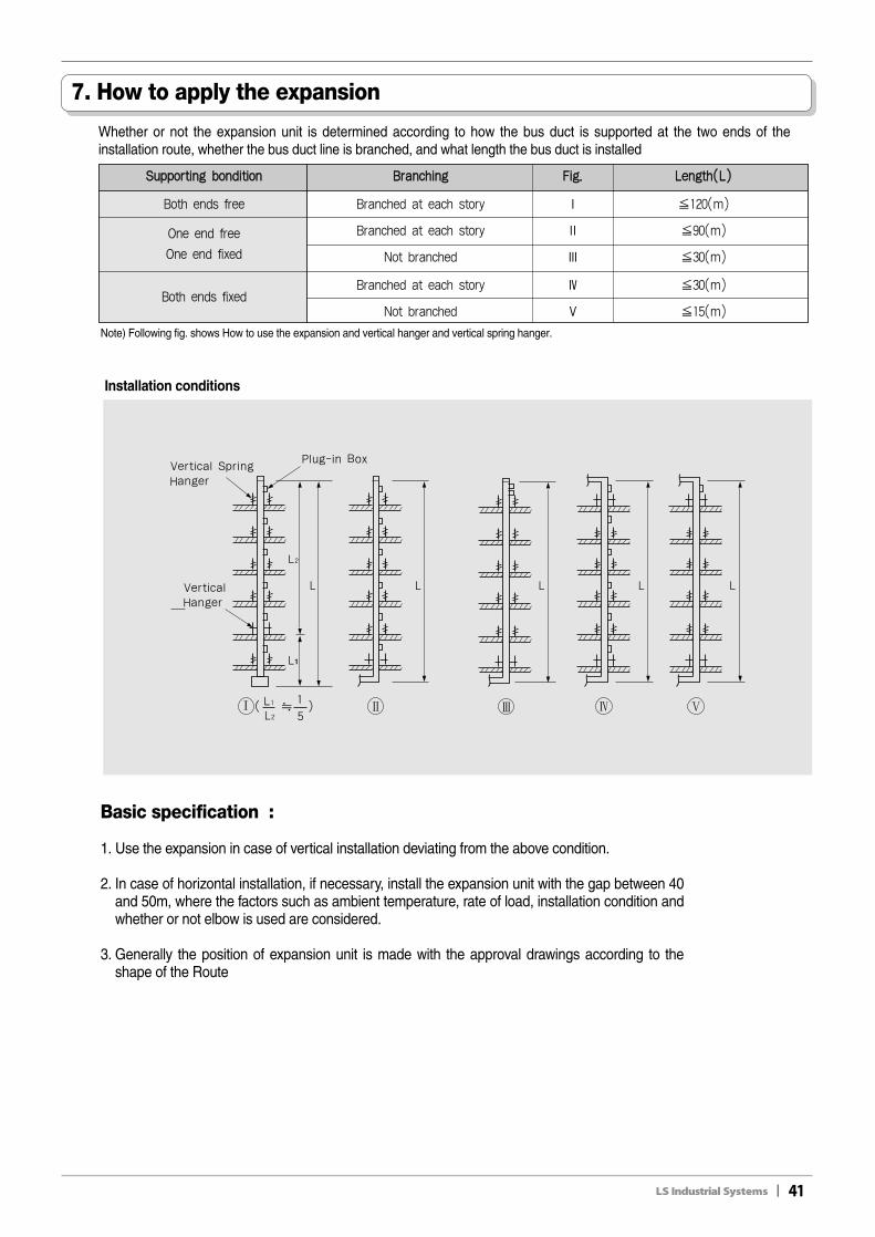
7. How to apply the expansion
Whether or not the expansion unit is determined according to how the bus duct is supported at the two ends of theinstallation route, whether the bus duct line is branched, and what length the bus duct is installed
Note) Following fig. shows How to use the expansion and vertical hanger and vertical spring hanger.
Basic specification :
1. Use the expansion in case of vertical installation deviating from the above condition.
2. In case of horizontal installation, if necessary, install the expansion unit with the gap between 40and 50m, where the factors such as ambient temperature, rate of load, installation condition andwhether or not elbow is used are considered.
3. Generally the position of expansion unit is made with the approval drawings according to theshape of the Route
SSuuppppoorrttiinngg bboonnddiittiioonn BBrraanncchhiinngg FFiigg.. LLeennggtthh((LL))
Both ends free Branched at each story Ⅰ �120(m)
One end free Branched at each story Ⅱ �90(m)
One end fixed Not branched Ⅲ �30(m)
Both ends fixedBranched at each story Ⅳ �30(m)
Not branched Ⅴ �15(m)
Installation conditions
42II
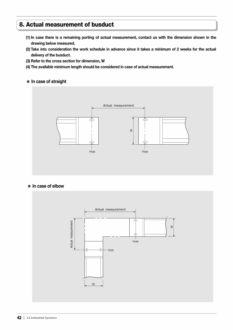
8. Actual measurement of busduct
(1) In case there is a remaining porting of actual measurement, contact us with the dimension shown in thedrawing below measured.
(2) Take into consideration the work schedule in advance since it takes a minimum of 2 weeks for the actualdelivery of the busduct.
(3) Refer to the cross section for dimension, W(4) The available minimum length should be considered in case of actual measurement.
●● In case of straight
●● In case of elbow
II43
1-1. Storage1) When the bus duct arrives at the site, check the type and quantity of the main unit parts against the
shipment list. See if any of them were damaged during the transpotation2) Keep the bus duct at a place, dry and free from moisture and water where there is no fear of being soiled or
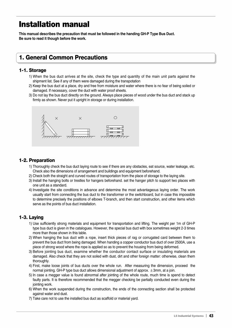
damaged. If necessary, cover the duct with water proof sheets.3) Do not lay the bus duct directly on the ground. Always place pieces of wood under the bus duct and stack up
firmly as shown. Never put it upright in storage or during installation.
1-2. Preparation1) Thoroughly check the bus duct laying route to see if there are any obstacles, eat source, water leakage, etc.
Check also the dimensions of arrangement and buildings and equipment beforehand.2) Check both the straight and curved routes of transportation from the place of storage to the laying site.3) Install the hanging bolts or trestles for hangers beforehand. set the hanger pitch to support two places with
one unit as a standard.4) Investigate the site conditions in advance and determine the most advantageous laying order. The work
usually start from connecting the bus duct to the transformer or the switchboard, but in case this impossibleto determine precisely the positions of elbows T-branch, and then start construction, and other items whichserve as the points of bus duct installation.
1-3. Laying1) Use sufficiently strong materials and equipment for transportation and lifting. The weight per 1m of GH-P
type bus duct is given in the catalogues. However, the special bus duct with box sometimes weight 2-3 timesmore than those shown in this table.
2) When hanging the bus duct with a rope, insert thick pieces of rag or corrugated card between them toprevent the bus duct from being damaged. When handing a copper conductor bus duct of over 2500A, use apiece of strong wood where the rope is applied so as to prevent the housing from being deformed.
3) Before jointing bus duct, examine whether the conductor contact surface or insulating materials aredamaged. Also check that they are not soiled with dust, dirt and other foreign matter: otherwise, clean themthoroughly.
4) First, make loose joints of bus ducts over the whole run. After measuring the dimension, proceed thenormal jointing. GH-P type bus duct allows dimensional adjustment of approx. ±3mm, at a join.
5) In case a megger value is found abnormal after jointing of the whole route, much time is spend to detectfaulty parts. It is therefore recommended that the megger checking be partially conducted even during thejointing work.
6) When the work suspended during the construction, the ends of the connecting section shall be protectedagainst water and dust.
7) Take care not to use the installed bus duct as scaffold or material yard.
Installation manual
1. General Common Precautions
This manual describes the precaution that must be followed in the handing GH-P Type Bus Duct.Be sure to read it though before the work.
44II
2. Jointing procedur
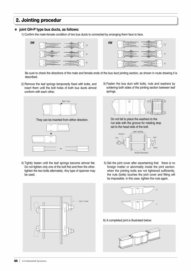
●● joint GH-P type bus ducts, as follows:1) Confirm the male-female condition of two bus ducts to connected by arranging them face to face.
3W 4W
Be sure to check the directions of the male and female ends of the bus duct jointing section, as shown in route drawing it isdescribed.
2) Remove the leaf springs temporarily fixed with bolts, andinsert them until the bolt holes of both bus ducts almostconform with each other.
3) Fasten the bus duct with bolts, nuts and washers bysoldering both sides of the jointing section between leafsprings.
4) Tightly fasten until the leaf springs become almost flat.Do not tighten only one of the bolt first and then the other.tighten the two bolts alternately. Any type of spanner maybe used.
They can be inserted from either direction. Do not fail to place the washers to the nut side with the groove for rotating stopset to the head side of the bolt.
5) Set the joint cover after ascertaining that there is noforeign matter or abormality inside the joint section.when the jointing bolts are not tightened sufficiently,the nuts (bolts) touches the joint cover and fitting willbe impossible. in this case, tighten the nuts again.
6) A completed joint is illustrated below.
II45
Take care of the following points when jointing the bus duct with the transformer and switchboarde
3. connection with equipment
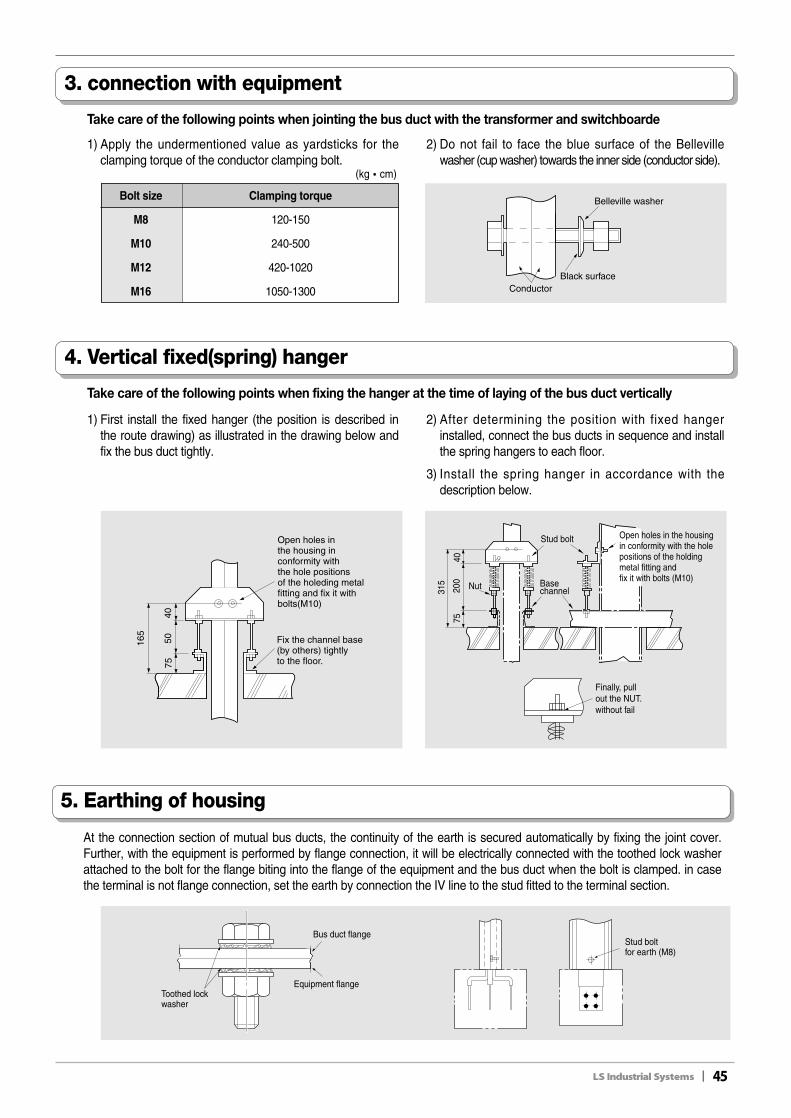
1) Apply the undermentioned value as yardsticks for theclamping torque of the conductor clamping bolt.
2) Do not fail to face the blue surface of the Bellevillewasher (cup washer) towards the inner side (conductor side).
Belleville washer
Black surfaceConductor
Bolt size Clamping torque
M8 120-150
M10 240-500
M12 420-1020
M16 1050-1300
(kg�cm)
Take care of the following points when fixing the hanger at the time of laying of the bus duct vertically
4. Vertical fixed(spring) hanger
1) First install the fixed hanger (the position is described inthe route drawing) as illustrated in the drawing below andfix the bus duct tightly.
2) After determining the position with fixed hangerinstalled, connect the bus ducts in sequence and installthe spring hangers to each floor.
3) Install the spring hanger in accordance with thedescription below.
Nut
Open holes in the housing in conformity with the hole positions of the holding metal fitting and fix it with bolts (M10)
Stud bolt
Base channel
40
315
7520
0
Finally, pull out the NUT.without fail
40
165
7550
Open holes in the housing inconformity with the hole positions of the holeding metal fitting and fix it with bolts(M10)
Fix the channel base (by others) tightly to the floor.
5. Earthing of housing
At the connection section of mutual bus ducts, the continuity of the earth is secured automatically by fixing the joint cover.Further, with the equipment is performed by flange connection, it will be electrically connected with the toothed lock washerattached to the bolt for the flange biting into the flange of the equipment and the bus duct when the bolt is clamped. in casethe terminal is not flange connection, set the earth by connection the IV line to the stud fitted to the terminal section.
Toothed lock washer
Bus duct flange
Equipment flange
Stud bolt for earth (M8)
46II
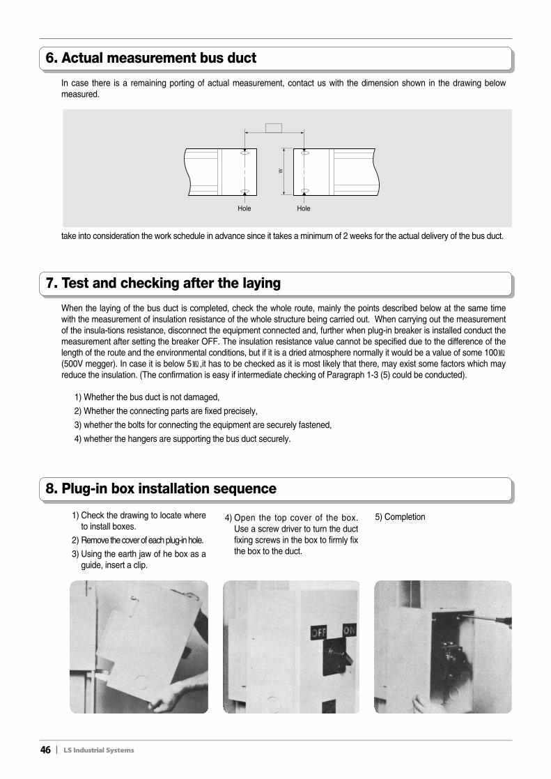
8. Plug-in box installation sequence
1) Check the drawing to locate whereto install boxes.
2) Remove the cover of each plug-in hole.
3) Using the earth jaw of he box as aguide, insert a clip.
4) Open the top cover of the box.Use a screw driver to turn the ductfixing screws in the box to firmly fixthe box to the duct.
5) Completion
6. Actual measurement bus duct
In case there is a remaining porting of actual measurement, contact us with the dimension shown in the drawing belowmeasured.
7. Test and checking after the laying
When the laying of the bus duct is completed, check the whole route, mainly the points described below at the same timewith the measurement of insulation resistance of the whole structure being carried out. When carrying out the measurementof the insula-tions resistance, disconnect the equipment connected and, further when plug-in breaker is installed conduct themeasurement after setting the breaker OFF. The insulation resistance value cannot be specified due to the difference of thelength of the route and the environmental conditions, but if it is a dried atmosphere normally it would be a value of some 100㏁(500V megger). In case it is below 5㏁,it has to be checked as it is most likely that there, may exist some factors which mayreduce the insulation. (The confirmation is easy if intermediate checking of Paragraph 1-3 (5) could be conducted).
1) Whether the bus duct is not damaged,
2) Whether the connecting parts are fixed precisely,
3) whether the bolts for connecting the equipment are securely fastened,
4) whether the hangers are supporting the bus duct securely.
take into consideration the work schedule in advance since it takes a minimum of 2 weeks for the actual delivery of the bus duct.
Hole Hole
II47
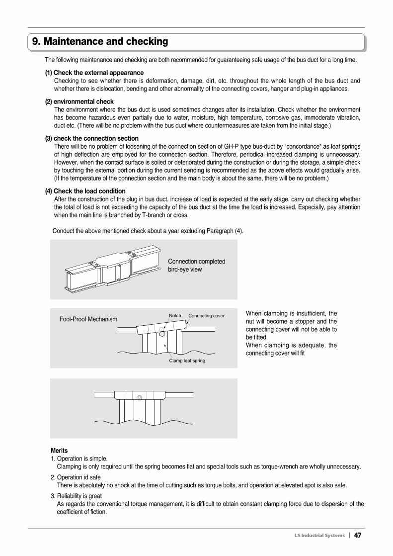
9. Maintenance and checking
The following maintenance and checking are both recommended for guaranteeing safe usage of the bus duct for a long time.
(1) Check the external appearanceChecking to see whether there is deformation, damage, dirt, etc. throughout the whole length of the bus duct andwhether there is dislocation, bending and other abnormality of the connecting covers, hanger and plug-in appliances.
(2) environmental checkThe environment where the bus duct is used sometimes changes after its installation. Check whether the environmenthas become hazardous even partially due to water, moisture, high temperature, corrosive gas, immoderate vibration,duct etc. (There will be no problem with the bus duct where countermeasures are taken from the initial stage.)
(3) check the connection sectionThere will be no problem of loosening of the connection section of GH-P type bus-duct by "concordance" as leaf springsof high deflection are employed for the connection section. Therefore, periodical increased clamping is unnecessary.However, when the contact surface is soiled or deteriorated during the construction or during the storage, a simple checkby touching the external portion during the current sending is recommended as the above effects would gradually arise.(If the temperature of the connection section and the main body is about the same, there will be no problem.)
(4) Check the load conditionAfter the construction of the plug in bus duct. increase of load is expected at the early stage. carry out checking whetherthe total of load is not exceeding the capacity of the bus duct at the time the load is increased. Especially, pay attentionwhen the main line is branched by T-branch or cross.
Conduct the above mentioned check about a year excluding Paragraph (4).
When clamping is insufficient, thenut will become a stopper and theconnecting cover will not be able tobe fitted.When clamping is adequate, theconnecting cover will fit
Merits1. Operation is simple.
Clamping is only required until the spring becomes flat and special tools such as torque-wrench are wholly unnecessary.
2. Operation id safeThere is absolutely no shock at the time of cutting such as torque bolts, and operation at elevated spot is also safe.
3. Reliability is greatAs regards the conventional torque management, it is difficult to obtain constant clamping force due to dispersion of thecoefficient of fiction.
Notch Connecting cover
Clamp leaf spring
Connection completedbird-eye view
Fool-Proof Mechanism

48II

II49

50II
Memo

Specifications in this catalog are subject to change without notice due to continuous product development and improvement.
�� HEAD OFFICELS Tower, 1026-6 Hokyeh 1dong, Dongan-gu, Anyang, Kyonggi-Do, 431-848, KoreaTel. (82-2)2034-4940~8Fax. (82-2)780-0382
�� CHEONG-JU PLANTCheong-Ju Plant #1, Song Jung Dong, Hung Duk Ku,Cheong Ju, 361-720, Korea
��For your safety, please read user's manual thoroughly before operating.
��Contact the nearest authorized service facility for examination, repair, or adjustment.
��Please contact qualified service technician when you need maintenance.Do not disassemble or repair by yourself!
��Any maintenance and inspection shall be performed by the personnel having expertise concerned.Safety Instructions
��LS Industrial Systems (Middle East) FZE ����Dubai, U.A.E. Address: P.O.Box-114216, API World Tower, 303B, Sheikhe Zayed Road, Dubai, U.A.E. Tel: 971-4-332-8289 Fax: 971-4-332-9444 e-mail: [email protected]
��Dalian LS Industrial Systems Co., Ltd. ����Dalian, ChinaAddress: No.15, Liaohexi 3-Road, Economic and Technical Development zone, Dalian 116600, ChinaTel: 86-411-8273-7777 Fax: 86-411-8730-7560 e-mail: [email protected]
��LS Industrial Systems (Wuxi) Co., Ltd. ����Wuxi, chinaAddress: 102-A , National High & New Tech Industrial Development Area, Wuxi, Jiangsu,214028, P.R.ChinaTel: 86-510-8534-6666 Fax: 86-510-522-4078 e-mail: [email protected]
��LS-VINA Industrial Systems Co., Ltd. ����Hanoi, VietnamAddress: Nguyen Khe - Dong Anh - Ha Noi - Viet NamTel: 84-4-882-0222 Fax: 84-4-882-0220 e-mail: [email protected]
��LS Industrial Systems Tokyo Office ����Tokyo, JapanAddress: 16FL, Higashi-Kan, Akasaka Twin Tower 17-22, 2-chome, Akasaka, Minato-ku Tokyo 107-8470, JapanTel: 81-3-3582-9128 Fax: 81-3-3582-2667 e-mail: [email protected]
��LS Industrial Systems Shanghai Office ����Shanghai, ChinaAddress: Room E-G, 12th Floor Huamin Empire Plaza, No.726, West Yan'an Road Shanghai 200050, P.R. ChinaTel: 86-21-5237-9977 (609) Fax: 89-21-5237-7191 e-mail: [email protected]
��LS Industrial Systems Beijing Office ����Beijing, ChinaAddress: B-Tower 17FL.Beijing Global Trade Center B/D. No.36, BeiSanHuanDong-Lu, DongCheng-District,Beijing 100013, P.R. ChinaTel: 86-10-5825-6025,7 Fax: 86-10-5825-6026 e-mail: [email protected]
��LS Industrial Systems Guangzhou Office ����Guangzhou, ChinaAddress: Room 1403,14F,New Poly Tower,2 Zhongshan Liu Road,Guangzhou, P.R. ChinaTel: 86-20-8326-6764 Fax: 86-20-8326-6287 e-mail: [email protected]
��LS Industrial Systems Chengdu Office ����Chengdu, ChinaAddress: 12Floor, Guodong Buiding, No52 Jindun Road Chengdu, 610041, P.R. ChinaTel: 86-28-8612-9151 Fax: 86-28-8612-9236 e-mail: [email protected]
��LS Industrial Systems Qingdao Office ����Qingdao, ChinaAddress: 7B40,Haixin Guangchang Shenye Building B, No.9, Shandong Road Qingdao 26600, P.R. ChinaTel: 86-532-8501-6568 Fax: 86-532-583-3793 e-mail: [email protected]
Leader in Electrics & Automation
��Global Network
www.lsis.biz
2008. 03 LS Bus Duct System(E) 2004.08/(02) 2008. 03 Printed in Korea STAFF
ⓒ 2004.8 LS Industrial Systems Co.,Ltd. All rights reserved.