lsm-500-075 rev h pilatus pc-12 - amazon s3 · lopresti aviation 772-562-4757 or fax 772-228-9750 ...
TRANSCRIPT
LoPresti Aviation 772-562-4757 or fax 772-228-9750 www.LoPrestiAviation.com
210 Airport Drive East, Sebastian, Florida, 32958, U.S.A.
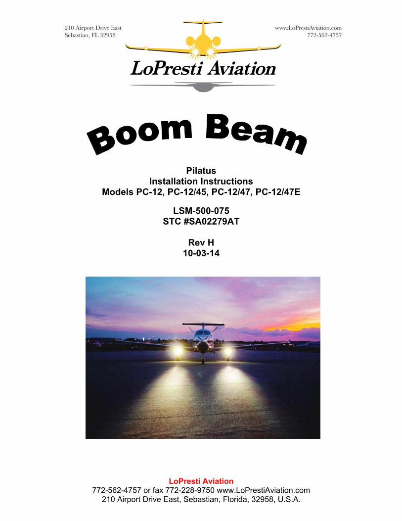
Pilatus
Installation Instructions Models PC-12, PC-12/45, PC-12/47, PC-12/47E
LSM-500-075 STC #SA02279AT
Rev H
10-03-14
LoPresti Aviation 772-562-4757 or fax 772-228-9750 www.LoPrestiAviation.com
210 Airport Drive East, Sebastian, Florida, 32958, U.S.A.
Revision History Rev Date Description
IR 03/28/08 1. Initial Release A 02/04/10 1. LSM-SCD-006-3 was LSM-500-200-128.
2. LSM-501-103-3 was LSM-501-103-1. 3. LSM-SCD-007-1 was LSM-500-314-3. 4. LSM-SCD-008-24W was LSM-500-331-12B. 5. KA3A1-CS125103224CR was KA3A1-CS125103210CR. 6. AN960-10 qty was 12. 7. Added NAS43DD3-48FC spacer qty 6. 8. Added Figure 1. 9. Revised Electrical Load Analysis format.
B 03/16/11 1. Added LSM-SCD-019-1 ballast as alternate. 2. CS125-103224CR was KA3A1-CS125103224CR and qty was
2. 3. CB9120V5 was KA5A1-2CB9120V5 and qty was 1. 4. Added CB92 adhesive kit qty 3. 5. Added CS125-103210CR as optional stud. 6. MS3367-1-9 qty was 16. 7. Revised electrical load analysis to add 60W kit installation
option. C 08/16/12 1. LSM-SCD-008-36W was LSM-SCD-008-24W.
2. Divided parts list into -1 35W and -3 60W kits.
D 01/31/13 1. Deleted CS125-103210CR from -1 kit. 2. Revised note 6 to allow slotting of the Pilatus clamp bracket.
E 08/29/13 1. MS3367-1-9 qty was 22. F 02/12/14 1. Deleted -1 35W ballast option.
2. Added -5 85W ballast option. 3. Revised electrical load analysis.
G 07/09/14 1. Added ClickBond Stud Installation Instructions. H 10/03/14 1. Added -7 for round version of 85 watt kit
2. Added LSM-501-103-5 abrastion shield to all installations. 3. Added operation to use abrastion shield to all installations.

LSM-500-075 Rev H Page 1
LoPresti Aviation 772-562-4757 or fax 772-228-9750 www.LoPrestiAviation.com
210 Airport Drive East, Sebastian, Florida, 32958, U.S.A.
BOOM BEAM Thank you for your purchase of the LoPresti Speed Merchants BOOM BEAM. We have written this Installation Manual to make your installation as easy and professional as possible. Before you start: READ ALL INSTRUCTIONS Call us at 800-859-4757 if you have any questions. Begin by checking the contents of your kit against the list below.
-3 60W Ballast Installation Kit
Nomenclature Part Number Vendor Quantity 60W Ballast 28V LSM-SCD-019-1 LoPresti Aviation
210 Airport Drive East Sebastian, FL 32958
2
LH Reflector Assy LSM-500-390-1
LoPresti Aviation
1
RH Reflector Assy LSM-500-390-2 LoPresti Aviation 1 Ballast to Power Wire
LSM-SCD-007-1 LoPresti Aviation 2
Ballast to Lamp/Starter Wire
LSM-SCD-008-36W LoPresti Aviation 2
Ballast Mounting Guide
LSM-501-103-3 LoPresti Aviation 2
Abrasion Mask LSM-501-103-5 LoPresti Aviation 1
Stud CS125-103210CR Click Bond 6 Cable Tie Mount CB9120V5 Click Bond 2 Adhesive Kit CB92 Click Bond 3 Washer AN960-10 12 Nut MS21042-3 6 Cable Tie Wraps MS3367-1-9 16 Connectors M81824-1-3 4 Shrink Tube M23053/5-106-0 8 inches

LSM-500-075 Rev H Page 2
LoPresti Aviation 772-562-4757 or fax 772-228-9750 www.LoPrestiAviation.com
210 Airport Drive East, Sebastian, Florida, 32958, U.S.A.
-5 Rectangular 85W Ballast Installation Kit
Nomenclature Part Number Vendor Quantity 85W Ballast 28V LSM-SCD-019-5 LoPresti Aviation
210 Airport Drive East Sebastian, FL 32958
2
LH Reflector Assy LSM-500-390-1
LoPresti Aviation
1
RH Reflector Assy LSM-500-390-2 LoPresti Aviation 1 Ballast to Power Wire
LSM-SCD-007-1 LoPresti Aviation 2
Ballast to Lamp/Starter Wire
LSM-SCD-008-36W LoPresti Aviation 2
Ballast Mounting Guide
LSM-501-103-3 LoPresti Aviation 2
Abrasion Mask LSM-501-103-5 LoPresti Aviation 1
Stud CS125-103210CR Click Bond 6 Cable Tie Mount CB9120V5 Click Bond 2 Adhesive Kit CB92 Click Bond 3 Washer AN960-10 12 Nut MS21042-3 6 Cable Tie Wraps MS3367-1-9 16 Connectors M81824-1-3 4 Shrink Tube M23053/5-106-0 8 inches

LSM-500-075 Rev H Page 3
LoPresti Aviation 772-562-4757 or fax 772-228-9750 www.LoPrestiAviation.com
210 Airport Drive East, Sebastian, Florida, 32958, U.S.A.
-7 Round Landing light, 85W Ballast Installation Kit
Nomenclature Part Number Vendor Quantity 85W Ballast 28V LSM-SCD-019-5 LoPresti Aviation
210 Airport Drive East Sebastian, FL 32958
2
LH Reflector Assy LSM-500-393-3
LoPresti Aviation
1
RH Reflector Assy LSM-500-393-4 LoPresti Aviation 1 Ballast to Power Wire
LSM-SCD-007-1 LoPresti Aviation 2
Ballast to Lamp/Starter Wire
LSM-SCD-008-36W LoPresti Aviation 2
Ballast Mounting Guide
LSM-501-103-3 LoPresti Aviation 2
Abrasion Mask LSM-501-103-5 LoPresti Aviation 1
Stud CS125-103210CR Click Bond 6 Cable Tie Mount CB9120V5 Click Bond 2 Adhesive Kit CB92 Click Bond 3 Washer AN960-10 12 Nut MS21042-3 6 Cable Tie Wraps MS3367-1-9 16 Connectors M81824-1-3 4 Shrink Tube M23053/5-106-0 8 inches
LSM-500-075 Rev H Page 4
LoPresti Aviation 772-562-4757 or fax 772-228-9750 www.LoPrestiAviation.com
210 Airport Drive East, Sebastian, Florida, 32958, U.S.A.
Installation Instructions
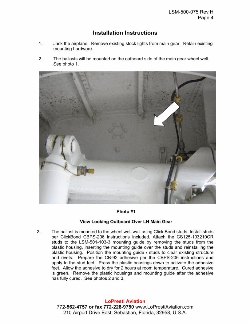
1. Jack the airplane. Remove existing stock lights from main gear. Retain existing mounting hardware.
2. The ballasts will be mounted on the outboard side of the main gear wheel well. See photo 1.
Photo #1
View Looking Outboard Over LH Main Gear
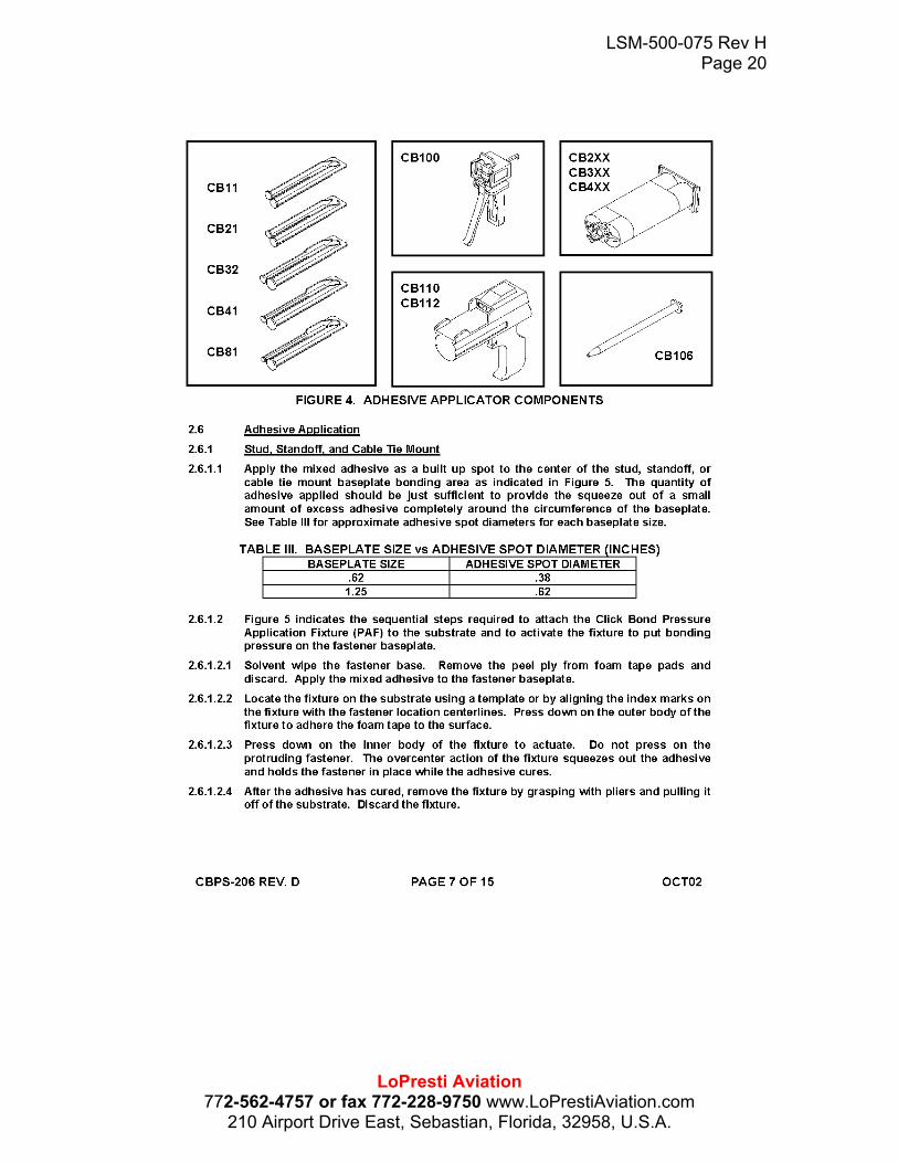
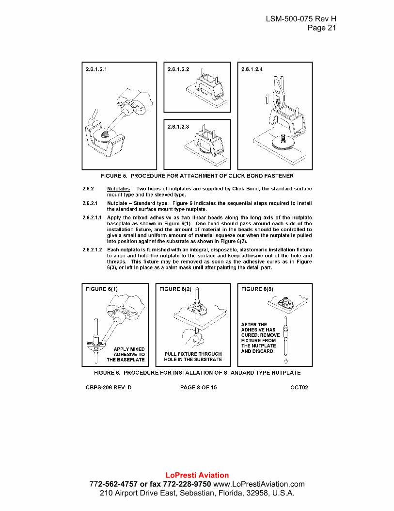
2. The ballast is mounted to the wheel well wall using Click Bond studs. Install studs per ClickBond CBPS-206 instructions included. Attach the CS125-103210CR studs to the LSM-501-103-3 mounting guide by removing the studs from the plastic housing, inserting the mounting guide over the studs and reinstalling the plastic housing. Position the mounting guide / studs to clear existing structure and rivets. Prepare the CB-92 adhesive per the CBPS-206 instructions and apply to the stud feet. Press the plastic housings down to activate the adhesive feet. Allow the adhesive to dry for 2 hours at room temperature. Cured adhesive is green. Remove the plastic housings and mounting guide after the adhesive has fully cured. See photos 2 and 3.
LSM-500-075 Rev H Page 5
LoPresti Aviation 772-562-4757 or fax 772-228-9750 www.LoPrestiAviation.com
210 Airport Drive East, Sebastian, Florida, 32958, U.S.A.
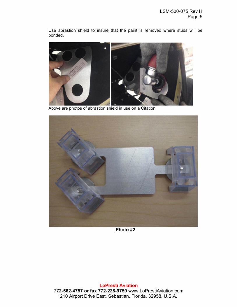
Use abrastion shield to insure that the paint is removed where studs will be bonded.
Above are photos of abrastion shield in use on a Citation.
Photo #2

LSM-500-075 Rev H Page 6
LoPresti Aviation 772-562-4757 or fax 772-228-9750 www.LoPrestiAviation.com
210 Airport Drive East, Sebastian, Florida, 32958, U.S.A.
Photo #3
3. Attach the ballast by sliding an AN960-10 washer over the Click Bond studs (3 places). Position ballast over studs. Add an AN960-10 washer and MS21042-3 nut on top of ballast and tighten. See photo 4.
LSM-500-075 Rev H Page 7
LoPresti Aviation 772-562-4757 or fax 772-228-9750 www.LoPrestiAviation.com
210 Airport Drive East, Sebastian, Florida, 32958, U.S.A.
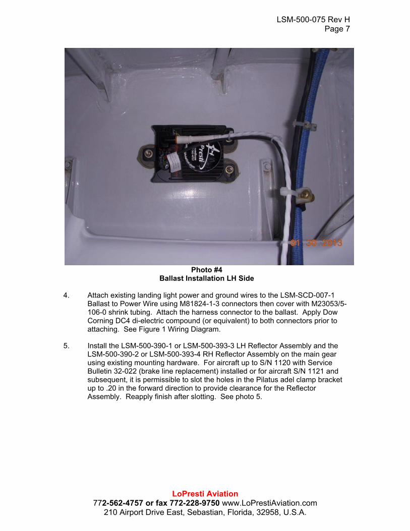
Photo #4
Ballast Installation LH Side
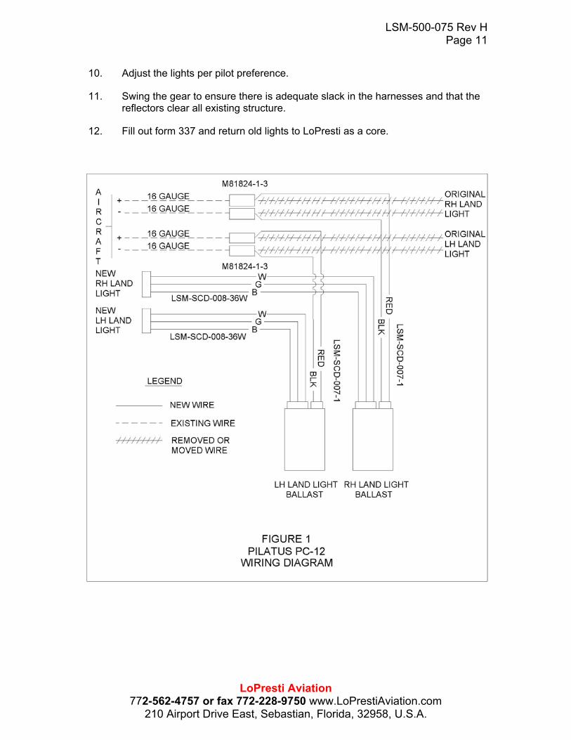
4. Attach existing landing light power and ground wires to the LSM-SCD-007-1 Ballast to Power Wire using M81824-1-3 connectors then cover with M23053/5-106-0 shrink tubing. Attach the harness connector to the ballast. Apply Dow Corning DC4 di-electric compound (or equivalent) to both connectors prior to attaching. See Figure 1 Wiring Diagram.
5. Install the LSM-500-390-1 or LSM-500-393-3 LH Reflector Assembly and the LSM-500-390-2 or LSM-500-393-4 RH Reflector Assembly on the main gear using existing mounting hardware. For aircraft up to S/N 1120 with Service Bulletin 32-022 (brake line replacement) installed or for aircraft S/N 1121 and subsequent, it is permissible to slot the holes in the Pilatus adel clamp bracket up to .20 in the forward direction to provide clearance for the Reflector Assembly. Reapply finish after slotting. See photo 5.

LSM-500-075 Rev H Page 8
LoPresti Aviation 772-562-4757 or fax 772-228-9750 www.LoPrestiAviation.com
210 Airport Drive East, Sebastian, Florida, 32958, U.S.A.
Photo #5
6. An alternate installation method is to install the reflector bracket on the outside of the tab on the gear leg. Adjust the brake line bracket slightly to clear. See photo 6.
Clamp Bracket

LSM-500-075 Rev H Page 9
LoPresti Aviation 772-562-4757 or fax 772-228-9750 www.LoPrestiAviation.com
210 Airport Drive East, Sebastian, Florida, 32958, U.S.A.
Photo #6
7. Attach the LSM-SCD-008-36W Ballast to Lamp/Starter Wire to the ballast and lamp/starter connectors. Apply Dow Corning DC4 di-electric compound (or equivalent) to both connectors prior to attaching.
8. Route the LSM-SCD-008-36W harness along the existing wire harness. Ensure enough slack is left in the harness to accommodate the rotating gear. Install CB9120V5 Click Bond cable tie mounts as required to secure both harnesses and attach using MS3367-1-9 cable ties. See photo 7.

LSM-500-075 Rev H Page 10
LoPresti Aviation 772-562-4757 or fax 772-228-9750 www.LoPrestiAviation.com
210 Airport Drive East, Sebastian, Florida, 32958, U.S.A.
Photo #7
9. Secure the wire harness to the lamp/starter connector as shown in photo 8 using safety wire.
Photo #8
LSM-500-075 Rev H Page 11
LoPresti Aviation 772-562-4757 or fax 772-228-9750 www.LoPrestiAviation.com
210 Airport Drive East, Sebastian, Florida, 32958, U.S.A.
10. Adjust the lights per pilot preference.
11. Swing the gear to ensure there is adequate slack in the harnesses and that the reflectors clear all existing structure.
12. Fill out form 337 and return old lights to LoPresti as a core.

LSM-500-075 Rev H Page 12
LoPresti Aviation 772-562-4757 or fax 772-228-9750 www.LoPrestiAviation.com
210 Airport Drive East, Sebastian, Florida, 32958, U.S.A.
Maintenance Requirements –
Instructions for Continued Airworthiness
“Modification of an aircraft by this Supplemental Type Certificate obligates the aircraft operator to include the maintenance information provided by this document in the operator’s Aircraft Maintenance Manual and the operator’s Aircraft Scheduled Maintenance Program.” 1. Maintenance Manual information for the Boom Beam is contained in LoPresti Speed
Merchants Installation Manual Number LSM-500-075 (this document), and should be placed into the operators appropriate airplane Maintenance Manual.
2. Line Replaceable Unit (LRU) part numbers and other necessary part numbers contained in the installation data package should be placed into the aircraft operators appropriate airplane Illustrated Parts Catalog (IPC).
3. Wiring diagram information contained in this data package should be placed into the aircraft operators appropriate airplane Wiring Diagram Manuals.
4. Scheduled Maintenance Program tasks to be added to the aircraft operators appropriate airplane maintenance program are as follows:
During an annual or 100-hour inspection interval, inspect the mechanical and electrical integrity of the BOOM BEAM equipment and components.
All fasteners must be checked for tightness and all cable ties must be checked for the security of the wiring harnesses. Loose or broken fasteners or cable ties must be tightened or replaced.
The wiring harnesses must be checked for frayed or damaged insulation, broken wires or connectors. Replace if damaged.
The bulb/starters, ballasts and reflectors must be checked for soundness in mechanical and electrical conditions. Cracked or broken bulb/starter, ballast, or reflector must be replaced.
Weight and Balance Information
No Change.

LSM-500-075 Rev H Page 13
LoPresti Aviation 772-562-4757 or fax 772-228-9750 www.LoPrestiAviation.com
210 Airport Drive East, Sebastian, Florida, 32958, U.S.A.
Electrical Load Analysis The existing aircraft lighting system is installed on the LH/RH main landing gear of the aircraft. Each light is rated at 250 watts and draws a maximum of 8.9 amperes at 28 VDC. Steady state values will be lower, as the lamps warm up. 60W Ballast Kit: The new Boom Beam installation replaces the two existing lamps with a ballast and lamp assembly; a total of two assemblies. Each ballast assembly draws a maximum of 5.9 amperes at 28 VDC at startup and then draws 2.4 amperes at steady state, after the lamps warm up. The total current required to operate the Boom Beam Lighting system is 13.0 amperes less than the existing system and therefore places no burden on the aircraft generating and distribution system. 85W Ballast Kit: The new Boom Beam installation replaces the two existing lamps with a ballast and lamp assembly; a total of two assemblies. Each ballast assembly draws a maximum of 8.4 amperes at 28 VDC at startup and then draws 3.0 amperes at steady state, after the lamps warm up. The total current required to operate the Boom Beam Lighting system is 11.8 amperes less than the existing system and therefore places no burden on the aircraft generating and distribution system.

LSM-500-075 Rev H Page 14
LoPresti Aviation 772-562-4757 or fax 772-228-9750 www.LoPrestiAviation.com
210 Airport Drive East, Sebastian, Florida, 32958, U.S.A.

LSM-500-075 Rev H Page 15
LoPresti Aviation 772-562-4757 or fax 772-228-9750 www.LoPrestiAviation.com
210 Airport Drive East, Sebastian, Florida, 32958, U.S.A.

LSM-500-075 Rev H Page 16
LoPresti Aviation 772-562-4757 or fax 772-228-9750 www.LoPrestiAviation.com
210 Airport Drive East, Sebastian, Florida, 32958, U.S.A.

LSM-500-075 Rev H Page 17
LoPresti Aviation 772-562-4757 or fax 772-228-9750 www.LoPrestiAviation.com
210 Airport Drive East, Sebastian, Florida, 32958, U.S.A.

LSM-500-075 Rev H Page 18
LoPresti Aviation 772-562-4757 or fax 772-228-9750 www.LoPrestiAviation.com
210 Airport Drive East, Sebastian, Florida, 32958, U.S.A.

LSM-500-075 Rev H Page 19
LoPresti Aviation 772-562-4757 or fax 772-228-9750 www.LoPrestiAviation.com
210 Airport Drive East, Sebastian, Florida, 32958, U.S.A.
LSM-500-075 Rev H Page 20
LoPresti Aviation 772-562-4757 or fax 772-228-9750 www.LoPrestiAviation.com
210 Airport Drive East, Sebastian, Florida, 32958, U.S.A.
LSM-500-075 Rev H Page 21
LoPresti Aviation 772-562-4757 or fax 772-228-9750 www.LoPrestiAviation.com
210 Airport Drive East, Sebastian, Florida, 32958, U.S.A.
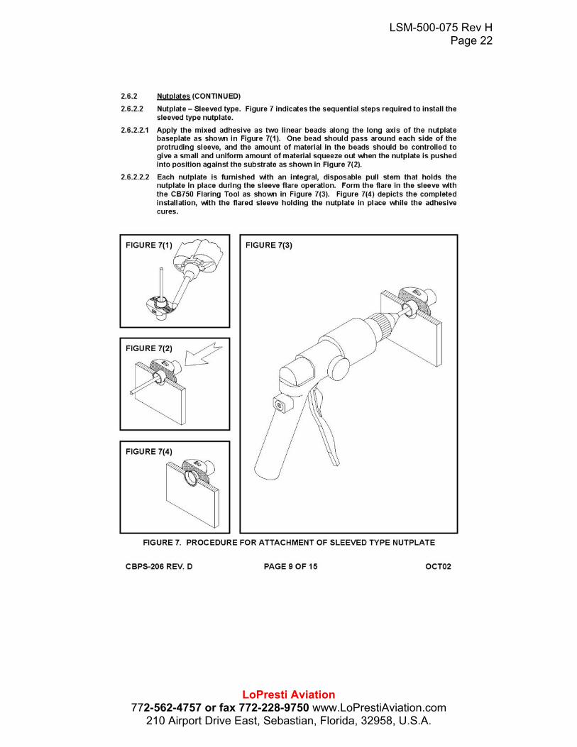
LSM-500-075 Rev H Page 22
LoPresti Aviation 772-562-4757 or fax 772-228-9750 www.LoPrestiAviation.com
210 Airport Drive East, Sebastian, Florida, 32958, U.S.A.
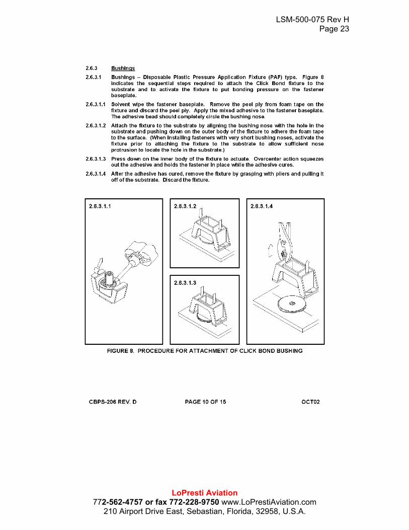
LSM-500-075 Rev H Page 23
LoPresti Aviation 772-562-4757 or fax 772-228-9750 www.LoPrestiAviation.com
210 Airport Drive East, Sebastian, Florida, 32958, U.S.A.

LSM-500-075 Rev H Page 24
LoPresti Aviation 772-562-4757 or fax 772-228-9750 www.LoPrestiAviation.com
210 Airport Drive East, Sebastian, Florida, 32958, U.S.A.

LSM-500-075 Rev H Page 25
LoPresti Aviation 772-562-4757 or fax 772-228-9750 www.LoPrestiAviation.com
210 Airport Drive East, Sebastian, Florida, 32958, U.S.A.
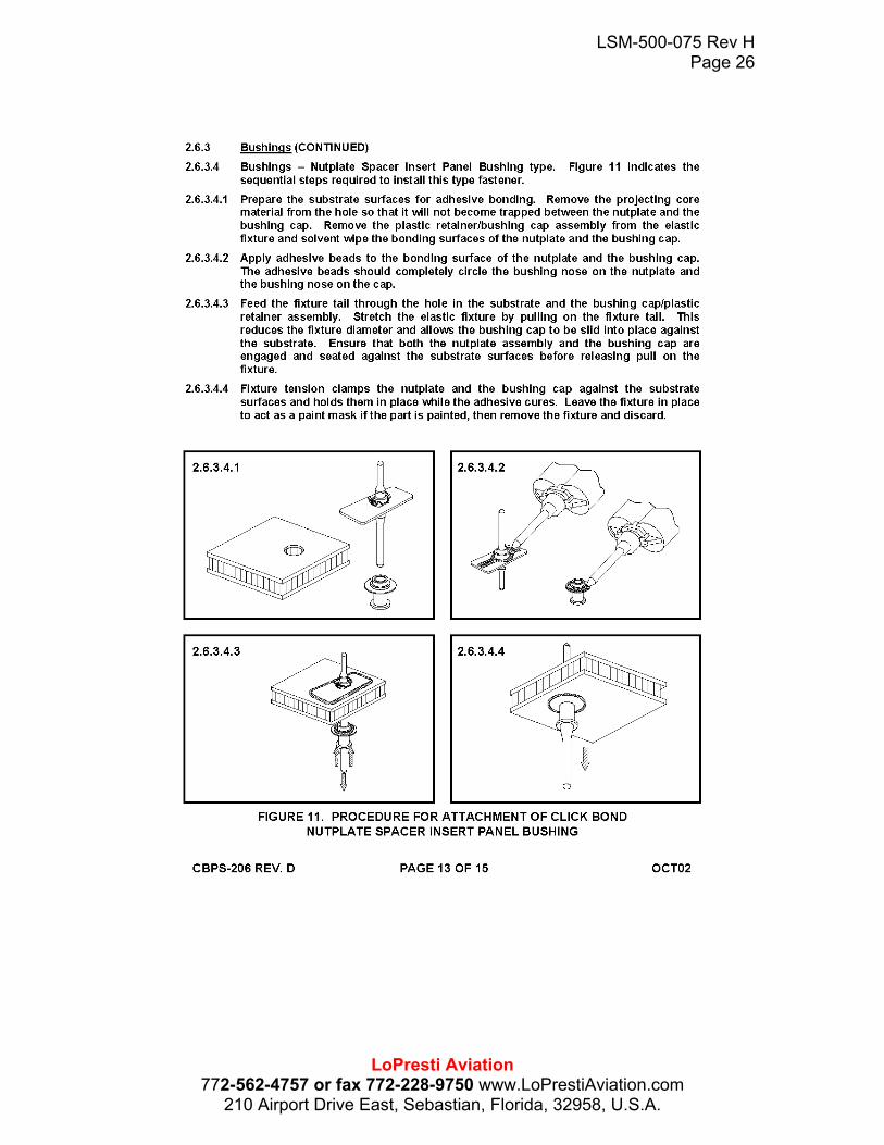
LSM-500-075 Rev H Page 26
LoPresti Aviation 772-562-4757 or fax 772-228-9750 www.LoPrestiAviation.com
210 Airport Drive East, Sebastian, Florida, 32958, U.S.A.
LSM-500-075 Rev H Page 27
LoPresti Aviation 772-562-4757 or fax 772-228-9750 www.LoPrestiAviation.com
210 Airport Drive East, Sebastian, Florida, 32958, U.S.A.

LSM-500-075 Rev H Page 28
LoPresti Aviation 772-562-4757 or fax 772-228-9750 www.LoPrestiAviation.com
210 Airport Drive East, Sebastian, Florida, 32958, U.S.A.