ltc 8900 series - bosch security...
TRANSCRIPT
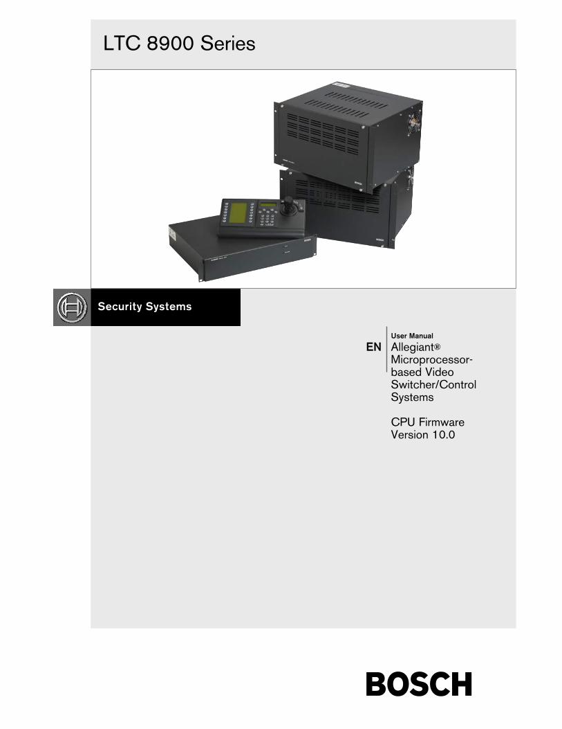
LTC 8900 Series
User Manual
EN Allegiant®Microprocessor-based VideoSwitcher/ControlSystems
CPU Firmware Version 10.0

EN | 2
Bosch Security Systems | March 17, 2009
LTC 8900 | User Manual | Table of Contents
Table of Contents1 INTRODUCTION . . . . . . . . . . . . . . . . . . . . . . . . . . . . . . . . . . . . . . . . . . . . . . . . . . . . . . . . . . . . . . . . . .32 THIS MANUAL . . . . . . . . . . . . . . . . . . . . . . . . . . . . . . . . . . . . . . . . . . . . . . . . . . . . . . . . . . . . . . . . . . . .33 VIDEO MONITOR DISPLAY . . . . . . . . . . . . . . . . . . . . . . . . . . . . . . . . . . . . . . . . . . . . . . . . . . . . . . . . .43.1 Time / Date . . . . . . . . . . . . . . . . . . . . . . . . . . . . . . . . . . . . . . . . . . . . . . . . . . . . . . . . . . . . . . . . . . . . . . . .43.2 Monitor Title/System Status Display . . . . . . . . . . . . . . . . . . . . . . . . . . . . . . . . . . . . . . . . . . . . . . . . . . . . .53.3 Monitor Message . . . . . . . . . . . . . . . . . . . . . . . . . . . . . . . . . . . . . . . . . . . . . . . . . . . . . . . . . . . . . . . . . . . .63.4 Broadcast Message . . . . . . . . . . . . . . . . . . . . . . . . . . . . . . . . . . . . . . . . . . . . . . . . . . . . . . . . . . . . . . . . . . .63.5 Program Prompts . . . . . . . . . . . . . . . . . . . . . . . . . . . . . . . . . . . . . . . . . . . . . . . . . . . . . . . . . . . . . . . . . . . .63.6 Camera Number . . . . . . . . . . . . . . . . . . . . . . . . . . . . . . . . . . . . . . . . . . . . . . . . . . . . . . . . . . . . . . . . . . . .73.7 Camera Title . . . . . . . . . . . . . . . . . . . . . . . . . . . . . . . . . . . . . . . . . . . . . . . . . . . . . . . . . . . . . . . . . . . . . . .73.8 Video Loss Detection . . . . . . . . . . . . . . . . . . . . . . . . . . . . . . . . . . . . . . . . . . . . . . . . . . . . . . . . . . . . . . . . .74 USER INFORMATION . . . . . . . . . . . . . . . . . . . . . . . . . . . . . . . . . . . . . . . . . . . . . . . . . . . . . . . . . . . . . .74.1 User Priority Access Table . . . . . . . . . . . . . . . . . . . . . . . . . . . . . . . . . . . . . . . . . . . . . . . . . . . . . . . . . . . . .85 KEYBOARD OPERATION . . . . . . . . . . . . . . . . . . . . . . . . . . . . . . . . . . . . . . . . . . . . . . . . . . . . . . . . . .85.1 General . . . . . . . . . . . . . . . . . . . . . . . . . . . . . . . . . . . . . . . . . . . . . . . . . . . . . . . . . . . . . . . . . . . . . . . . . .85.2 System Commands . . . . . . . . . . . . . . . . . . . . . . . . . . . . . . . . . . . . . . . . . . . . . . . . . . . . . . . . . . . . . . . . . .85.3 Switcher Commands . . . . . . . . . . . . . . . . . . . . . . . . . . . . . . . . . . . . . . . . . . . . . . . . . . . . . . . . . . . . . . . . .95.4 Controlling Camera Movement . . . . . . . . . . . . . . . . . . . . . . . . . . . . . . . . . . . . . . . . . . . . . . . . . . . . . . . .95.5 Alarm Commands . . . . . . . . . . . . . . . . . . . . . . . . . . . . . . . . . . . . . . . . . . . . . . . . . . . . . . . . . . . . . . . . . .115.6 Sequence Control . . . . . . . . . . . . . . . . . . . . . . . . . . . . . . . . . . . . . . . . . . . . . . . . . . . . . . . . . . . . . . . . . . .125.7 Sequence Programming . . . . . . . . . . . . . . . . . . . . . . . . . . . . . . . . . . . . . . . . . . . . . . . . . . . . . . . . . . . . . .136 KEYBOARD USER FUNCTIONS . . . . . . . . . . . . . . . . . . . . . . . . . . . . . . . . . . . . . . . . . . . . . . . . . . . . .146.1 General . . . . . . . . . . . . . . . . . . . . . . . . . . . . . . . . . . . . . . . . . . . . . . . . . . . . . . . . . . . . . . . . . . . . . . . . . .147 MAINTENANCE . . . . . . . . . . . . . . . . . . . . . . . . . . . . . . . . . . . . . . . . . . . . . . . . . . . . . . . . . . . . . . . . . .237.1 Cleaning the Keyboard . . . . . . . . . . . . . . . . . . . . . . . . . . . . . . . . . . . . . . . . . . . . . . . . . . . . . . . . . . . . . .238 LTC 8900 CHARACTER SET . . . . . . . . . . . . . . . . . . . . . . . . . . . . . . . . . . . . . . . . . . . . . . . . . . . . . . . .249 ERROR MESSAGES . . . . . . . . . . . . . . . . . . . . . . . . . . . . . . . . . . . . . . . . . . . . . . . . . . . . . . . . . . . . . . . .3110 GLOSSARY OF TERMS . . . . . . . . . . . . . . . . . . . . . . . . . . . . . . . . . . . . . . . . . . . . . . . . . . . . . . . . . . . . .33

EN | 3
Bosch Security Systems | March 17, 2009
LTC 8900 | User Manual | Introduction
1 INTRODUCTIONThe LTC 8900 Allegiant Series is a videoswitching/controller system designed to handle up to4096 cameras and 512 monitors, in a full crosspointconfiguration. Although the LTC 8900 Series is a verysophisticated product, it has been designed with thenovice user in mind. The system can be operatedusing its default configuration, or it can be customizedusing the PC-based software package.
The LTC 8900 Series Allegiant systems represent adramatic breakthrough in CCTV switcher/controllers,and are backed by years of expertise in designing andmanufacturing closed-circuit video equipment.
The LTC 8900 Series Allegiant system provides thefollowing features:
1. Full camera switching/control on all monitors
2. Up to 120 keyboards
3. Up to 2048 alarm inputs
4. 3 user-selectable pre-defined alarm responsemodes
5. 64 priority levels for on-site receiver/drivercontrol
6. SalvoSwitching®
7. 256 programmable sequences
8. Alarm call-up of pre-position scenes
9. RS-232 interface ports for Computer, LoggingPrinter, etc.
10. Keyboard Logon/Logoff security function
11. 128 Users with selectable password security
12. 16-character camera titles and 12-charactermonitor titles
13. User-selectable 40-character camera titles using3rd line of on-screen text.
14. User-selectable 2-digit site plus 4-digit cameranumber mode.
15. Selectable time/date format
16. Local keyboard test function
17. Table and Sequence printout feature
18. Selectable RS-232 communication parameters
19. Integral video loss detection
20. Satellite system configurations
21. Restrictions for user/keyboard access to cameras
22. Restrictions for user/keyboard access toreceiver/drivers
23. Restrictions for user access to keyboard
24. Restrictions for user/keyboard access tomonitors
25. Programmable User names and ID numbers
26. Programmable zoned alarm call-ups
27. Advanced alarm features
28. Programmable camera numbers
29. Programmable receiver/driver functions onalarm
30. Programmable 128 Time Activated Events
31. Programmable receiver/driver functions insequences
32. Monitor Broadcast messages
33. Alarm title designations
34. Personal Computer-based system diagnostics
35. Personal Computer-based system configuration
The LTC 8900 Series provides full control of on-sitereceiver/driver units, including the AutoDome® Seriesof integral pan/tilt/zoom dome cameras.
Add the LTC 8016/90 accessory unit to providecommunication capability with Dinion® andAutoDome® cameras, using BilinxTM technology.
2 THIS MANUALEach section in this manual covers one aspect of thesystem functions. System Operators should becomefamiliar with the Video Monitor Display section, UserInformation section, Keyboard Operation section, andError Message sections. System Administrators shouldbecome familiar with all operator sections, in additionto the sections on, Keyboard User Functions, and LTC 8900 CHARACTER SET table.

EN | 4
Bosch Security Systems | March 17, 2009
LTC 8900 | User Manual | Video Monitor Display
Typically, various system parameters are configuredby the installer via the PC-based configurationsoftware package at installation. These programmableoptions include entry of camera titles, userinformation, alarm functions, lockout tables,sequences, time events, and other operationalfunctions. These programmable features have a greateffect on system operation and operator privileges.
3 VIDEO MONITOR DISPLAYThe LTC 8900 Series systems feature an integral textoverlay with two or three rows of 24 characters each.Over 4000 characters can be displayed. Refer to the LTC8900 CHARACTER SET section for further details.
NOTE: If no video signal is present, a new line willappear stating: VIDEO NOT PRESENT.
The display is broken down into three areas as shown inthe FIGURE 1 below:
3.1 Time / Date
The time/date display is generated by the system CPUmicroprocessor module. It is crystal controlled andbattery protected for one year (minimum) without power.The display is updated once per second, and all monitorsupdate simultaneously. The time/date message is alwayson the right-hand side of the video display, with the timeon the top line. Time displays hours, minutes, andseconds, and can be set to either 12-hour or 24-houroperation. The date is available in three user-selectableformats:
1. U.S. Format: MM/DD/YY
2. International Format: DD/MM/YY
3. Asian Format: YY/MM/DD
Figure 1 Monitor Overlay Display
XXXX Status/Title 12:00:00Camera Title 11-26-90
Extended Camera Title/Monitor Title
xx
User-selectable 2-digit “Site” Number Mode
12-character SystemStatus Display or
Monitor Title
CameraNumber
12- or 24-hourTime Display
16-characterCamera Title
User-selectableThird Line Mode
3 Selectable Date Formats:(MM-DD-YY, DD-MM-YY,YY-MM-DD)
PM

EN | 5
Bosch Security Systems | March 17, 2009
LTC 8900 | User Manual | Video Monitor Display
3.2 Monitor Title/System Status
Display
The monitor title/system status display area is a 12-column display to the right of the camera number. It is unique on each monitor, and has different uses, someof which may be user-selected via keyboard. These usesare described below:
Format of Monitor Overlay s
System Status Display
1 2 3 4 5 6 7 8 9 10 11 12
A A A M C E R M A S S S
l l l o a r e o b e e e
a a a n m r m n s q q q
r r r o /
m m m A A r L L R N N S
r r / o o e u u t
m m D c c l m m a
I k k t
R
3.2.1 System Status Display
If this display is enabled (factory default), it allows theAllegiant system to dynamically inform the user of systemstatus. The 12-column display is divided into smallermessage columns (per above figure), in which specialcharacters report the following:
Whether the switcher is running or stopped.
The switcher s direction.
Whether a monitor or remote camera is locked.
The alarm status of the camera and monitor.
3.2.2 Locations 1, 2, and 3 - Alarm Indication
When the monitor overlay is in Status Display mode,locations 1 through 3 indicate whether a camera on themonitor is in alarm. If the on-screen camera is currentlyin alarm, an ALM message in a box will flash at thislocation. A ** in a box means that a camera other thanthe on-screen camera is in alarm. If no cameras arecurrently in alarm on this monitor, these spaces areblank. When a monitor has cameras in alarm, pressNEXT, RUN, or PREVIOUS on the keyboard to movethrough the alarm sequencer rather than the regularcamera sequencer. The alarm switcher status will bedisplayed in location 6 using symbols described.
3.2.3 Location 4 - Monitor Arm Status Indication
In the MONITOR ARMED location, the characters SM
or DM will appear if the monitor is armed for alarm. SM
means that the monitor is a step or sequence monitor, andwill automatically step through multiple alarm videos. DM
indicates that the monitor is a display or review monitor,which will collect alarm videos from one or more stepmonitors.
When an alarm occurs, the alarmed camera s video willreplace the current display of the monitor. If the monitoris not armed, this location is blank.
3.2.4 Location 5 - Camera Arm Status Indication
In the CAMERA ARMED location characters CA aredisplayed if the camera being viewed is armed for alarmon that monitor. If the alarm signal associated with thiscamera becomes active, the camera will be displayed onthe appropriate armed monitors.
3.2.5 Location 6 - Error Indication
This location displays ERR when a user error occurs. Thespecific error number appears in locations 7 and 8, andalso in the Camera Number Display field on the keyboard.The display will return to normal after a few seconds, orif the user presses ENTER on the keyboard.
Location 6 is also used to indicate the sequencingdirection when alarms occur. Possible charactercombinations are:
1. ^R: the alarms are sequencing in a forwarddirection.
2. RV: the alarms are sequencing in a reversedirection.
3. ^S: the alarm sequencing has stopped, but ifstarted again, would sequence in a forwarddirection.
4. SV: the alarm sequencing has stopped, but ifstarted again, would sequence in a reversedirection.
Location 6 can also be used to display a symbolindicating pan/tilt/zoom-equipped cameras. Using thePC-based Master Control Software or keyboard UserFunctions 34 and 35, controllable cameras can beindividually configured to display a symbol in location 6 when viewed on a system monitor.
EN | 6
Bosch Security Systems | March 17, 2009
LTC 8900 | User Manual | Video Monitor Display
3.2.6 Location 7 - Remote Lock Indication
This location will display characters RL to indicate thatcontrol over the movements of the camera being viewedhave been locked by a user. Control over this camera isnow possible only by the user who locked the camera, orhas higher priority. If the camera is not locked, the icon isnot displayed. If a user error has occurred, this locationwill temporarily hold part of the error number.
3.2.7 Location 8 - Monitor Lock Indication
This location will display characters ML to indicate thatthe monitor has been locked by a user. The cameracurrently being viewed cannot be changed except by theuser who locked the monitor, or has higher priority. Ifthe monitor is not locked, the icon will not be displayed.If a user error has occurred, this location will temporarilyhold part of the error number.
3.2.8 Location 9 - Sequence Type Indication
This location displays the type of sequence currentlyloaded on the monitor. An absolute sequence is indicated bythe characters AS, meaning that monitors programmed inthe sequence program refer to the exact monitor(s) wherethe sequence may be run. Sequences created via thesystem keyboards are always of this type, so absolutesequences are the only type possible in a base system.Relative sequences are designated by the characters RS inthis location. These sequences will run on any monitor,or group of monitors, and can only be programmed viathe Master Control Software on a PC.
3.2.9 Locations 10 and 11 - Sequence Number
The sequence number currently active for the monitor isdisplayed here. This is a number between 1 and 60, or 00to indicate that no sequence is loaded.
3.2.10 Location 12 - Sequence Status Indication
This location indicates the status of the sequence active inthe monitor. Possible character combinations are:
1. ^R: the current sequence is sequencing in aforward direction.
2. RV: the current sequence is sequencing in areverse direction.
3. ^S: the sequence is stopped, but if started again,would sequence in a forward direction.
4. SV: the sequence is stopped, but if started again,would sequence in a reverse direction.
3.3 Monitor Title
The monitor message is a stationary 12-character titlewhich may be placed on a monitor instead of the System Status display. Specific monitor messages can be programmed from either the keyboard (see User Function 17 in SECTION 6) or the PC-basedMaster Control Software.
3.4 Broadcast Message
A message can be sent by the operator of the PC, via thePC-based Master Control Software, to all the monitors inthe system. This message may be up to 24 characters,and can notify all users at all monitor locations ofimportant information. The message, along with itsbeginning and ending time and date, is also printed onthe logging printer (if one is connected), as well as anyuser acknowledgment. The broadcast duration may be setfor 1 to 60 seconds, and is displayed on a line by itself.
3.5 Program Prompts
During entry of sequence programming via the keyboard,the Allegiant system prompts the user on the monitor hiskeyboard is currently controlling. The display will returnto its previous form when the user leaves the programmingmode.

EN | 7
Bosch Security Systems | March 17, 2009
LTC 8900 | User Manual | Video Monitor Display
3.6 Camera Number
The left-most display on the top line shows the system-generated camera number, and is always displayed. Thisunique number identifies this camera when using thekeyboard for video call-ups. In base systems, this numberis the same as the numbered BNC connector that thecamera is plugged into on the rear of the bay (physicalcamera number). However, the PC-based Master ControlSoftware package can be used to change this number toany unique number between 1 and 9999. The option todisplay a 2-digit site number above the 4-digit cameranumber is user-selectable. This "6-digit Camera ID"mode is especially useful when groups of cameras arelocated in separate buildings, floors, or other commonareas.
3.7 Camera Title
The camera identification display (the first 16 characters of the lower line) is used to label eachcamera. Each camera has its own title, displayedwhenever that camera is called up for viewing. A userselectable option provides the ability to display a 3rd lineof on-screen text. This 3rd line can be configured todisplay up to 24 additional camera title characters (40characters total) or a 12-character monitor title. The titlecharacters can be entered from the keyboard viakeyboard User Function 9, or via the PC-based MasterControl Software.
3.8 Video Loss Detection
The Allegiant system is capable of detecting loss of video.When the unit detects that an input has lost video, aVIDEO NOT PRESENT message is displayed on therespective monitor.
NOTE: It may take up to five seconds for the unit todisplay the video loss message when a video source isdisconnected.
4 USER INFORMATIONThere are 64 levels of user priority in the Allegiantsystem. Each of the 128 users in the Allegiant systemhas a default priority level assignment. These userlevels determine access to various system functions,and user control prioritization of monitors andpan/tilt/zoom-equipped camera sites. Generally, userswith higher priority (highest = 1) can regain controlover monitors or pan/tilt/zoom cameras locked byanother user.
User Default Priority Default
Number Password Level Keyboard
1 1 1 12 2 2 23 3 2 34 4 2 45 5 64 56 6 64 67 7 64 78 8 2 89 9 2 9
10 10 2 1011 11 2 1112 12 2 1213 13 2 1314 14 2 1415 15 2 1516 16 2 1617 17 2 1718 18 2 1819 19 2 1920 20 2 2021 21 64 2122 22 64 2223 23 64 2324 24 64 24
(Continue Sequence)63 63 64 6364 64 64 6465 65 64 None66 66 64 None
(Continue Sequence)127 127 64 None128 128 64 None
The 64 priority level user assignments can be changedusing the PC-based Master Control Software package,but for a base system, the table above shows thedefault values set. Note that in base systems where thelogin feature has not been selected, the first 64 usernumbers are automatically associated with a specifickeyboard port. This essentially sets the keyboard asthe priority determiner. Also shown in the table arethe default user passwords assigned to each user as thesystem is shipped from the factory. Once a user islogged-on to the system, the password can be changedvia keyboard User Function 10. Refer to Section 6Keyboard User Functions.

EN | 8
Bosch Security Systems | March 17, 2009
LTC 8900 | User Manual | Keyboard Operation
4.1 User Priority Access Table
The following table shows system function access forthe 64 levels of users.
5 KEYBOARD OPERATION 5.1 General
Primary operation of an Allegiant switcher is controlledvia the system keyboard. The 2 types of keyboardsavailable are:
Conventional LTC 8555 Series (incorporatesLEDs and pushbuttons)
IntuiKey model (uses dynamic LCD menuscreens)
General operation steps for both keyboard models follow.Refer to the User Manual provided with the keyboard foradditional information.
As the system is supplied from the factory, various user-selectable features have been set to a default state. Sincethese features are user-selectable and can have asignificant effect on the system operation, note anychanges that may be in effect.
5.2 System Commands
5.2.1 Keyboard Login Procedure
Keyboard modes:Via Factory Default Settings, a keyboard isready for use as soon as power is applied to thesystem.
The system operator must logon to a keyboard toaccess the system. When a system is configured touse the keyboard logon, operators must be pre-assigned a user number and password. Up to 128user numbers are available, each having defaultpriority level. User specific priority levels can onlybe changed via the PC-based LTC 8059 MasterControl Software (MCS) program. Refer to theMCS manual for details.
If the logon feature is enabled and an operator is notlogged in, LED keyboards show flashing dashes in theirdisplay. IntuiKey keyboards prompt for a user numberwhen entering the main Allegiant softscreen menu.
Priority Levels
System Function 1 2 to 7 8 to 64
Switch Video On Monitors Yes Yes Yes
Control Pan/Tilt/Zoom Camera Yes Yes Yes
Lock Monitor Yes Yes Yes
Lock Pan/Tilt/Zoom Camera Yes Yes Yes
Acknowledge Alarms Yes Yes Yes
Perform Keyboard Test Yes Yes Yes
Show Keyboard Number Yes Yes Yes
Activate Keyboard Beeper Yes Yes Yes
Change User Password Yes Yes Yes
Program Sequences Yes Yes No
Position Video Overlay Display Yes Yes No
Set Overlay Display Brightness Yes Yes No
Select Overlay Display Type Yes Yes No
Set System Time/Date Yes Yes No
Program Pre-positions Yes Yes No
Set Time/Date Format Yes No No
Set Camera and Monitor Titles Yes No No
Enable Time Events Yes No No
Enable 3-line Title Mode Yes No No
Enable 6-digit Camera ID Mode Yes No No
Enable Vertical Phase Set Yes No No
Reset System Yes No No
Printout Tables and Sequences Yes No No
Default Monitor Overlay Yes No No
Select Alarm Response Mode Yes No No
Select Printer Mode Yes No No
Designate Alarm Monitor Type Yes No No
Select Keyboard Login Yes No No
Select Console Login Yes No No
Configure/Reset RS-232 Ports Yes No No

EN | 9
Bosch Security Systems | March 17, 2009
LTC 8900 | User Manual | Keyboard Operation
Enter your assigned user number via the numeric keypadand press ENTER. When prompted, enter the password.Invalid passwords cause the keyboard to revert to itsinitial state. Once the login is successful, the keyboardwill show camera and monitor numbers in its display.
Upon logging in, the monitor controlled by the keyboardmay automatically switch to a pre-assigned cameranumber. This function is only applicable if enabled bythe system administrator (via the MCS package), andmay not function if the monitor is running a sequence,and/or in an alarm condition.
5.2.2 Keyboard Logoff Procedure
If the login feature has been enabled, press User Logoff[User, then OFF]. If the feature has not been enabled,this action is not applicable.
5.3 Switcher Commands
5.3.1 Camera Selection
The keyboard default mode is the camera mode, so entera camera number for viewing, and press ENTER.
If the Allegiant is configured to operate in "6-digitCamera ID" mode, up to 6 digits can be entered. If thenew camera is at the same "site" as the current camera,simply enter 1 to 4 camera number digits. If the desired camera is at a different "site", 5 or 6 digitsmust be entered. The first and second digits would bethe site number and the remaining 4 digits, including anyleading zeros would be the camera number at that site.
5.3.2 Monitor Selection
Press MON [Monitor], enter a monitor number, andpress ENTER.
5.4 Controlling Camera Movement
5.4.1 General
Camera positioning is controlled via an eight-way joystickon the right-hand side of the keyboard. This joystickmoves the camera pan/tilt, (if equipped), up, down, left,right, or diagonally. Rotate the joystick knob to controlthe zoom lens in or out.
Moving the joystick up and to the right, simultaneously,moves the camera in a diagonal direction. Rotating theZOOM control knob causes the lens to either zoom in orout. The direction of its response depends on thecamera/lens model, and certain system configurationsettings determined at installation.
Up to four pan/tilt/zoom commands may be sent to aremote camera site at a time (Example - Zoom In, FocusFar, Pan Left, and Tilt Down). The three zoom lensfunctions can also be sent simultaneously (Example -Zoom Out, Focus Near, Iris Open).
5.4.2 Focus and Iris Lens Control
The lens control buttons are on the right-hand side of thekeyboard. The camera’s zoom lens, if equipped, can becontrolled to focus near or far, and open or close the iris(if the lens supports manual iris operation).
5.4.3 Lock or Unlock Control of a Camera
When using IntuiKey keyboards, press Device Lockout,located on the main Allegiant menu, to enter a menuscreen for these options.
With LTC 8555 Series Keyboards, press Lock, then ONto lock a camera, or OFF to unlock a camera. If thecamera to be locked is not the one currently beingviewed, enter the camera number via the numerickeyboard (but do not press ENTER) before pressingLock.
If the Status option is enabled, the section of the on-screen overlay between the camera number and the timeshows RL, indicating the camera is locked. Activating acamera lock immediately prevents other operators (unlessthey have a higher priority) from controlling the lockedpan/tilt/zoom camera. Remember to unlock the camerawhen finished so other operators can access it.
5.4.4 Lock or Unlock Control of a Monitor
When using IntuiKey keyboards, press Device Lockout,located on the main Allegiant menu, to enter a menuscreen with these options.
NOTE: The information below applies to both
IntuiKey keyboards and LTC 8555 Series keyboards.
Where applicable, button designations specific to
IntuiKey keyboards will be shown in plain text.
Equivalent button designations that apply to
LTC 8555 Series keyboards will be placed in [ ]
immediately after the IntuiKey button text.

EN | 10
Bosch Security Systems | March 17, 2009
LTC 8900 | User Manual | Keyboard Operation
With LTC 8555 Series keyboards, press Monitor, Lock,then ON to lock a monitor, or OFF to unlock themonitor. If the monitor to be unlocked is not the onecurrently being controlled by the keyboard, enter themonitor number (but do not press ENTER) after pressingMonitor.
If the Status option is enabled, the section of the on-screen overlay between the camera number and the timeshows ML, indicating the monitor is locked. This preventsother operators from changing the video on the monitorbeing used (unless they have a higher priority).Remember to unlock the monitor when finished so otheroperators can access it.
If an operator with a higher priority accesses a lockedmonitor and switches to a different camera, the lock isautomatically removed.
5.4.5 Recording a Camera Pre-position Scene
Select a camera with pan/tilt/zoom control, with pre-position options. Using the joystick and lens controls,adjust the camera to view the scene to be stored. When using IntuiKey keyboards, press Camera Control,located on the main Allegiant menu screen to enter amenu screen with this option. Press Set Shot [Set], thenselect the scene number via the numeric keypad, andpress ENTER. The camera position will now be storedfor recall later.
If an AutoDome Series camera is being used, certain pre-position commands are also used to activate operationalfeatures/functions. Refer to the AutoDome operationmanual for complete information. If an Allegiantconventional receiver/driver is being controlled, thepan/tilt and zoom lens must have the necessary optionsfor pre-position operation.
On certain models of AutoDomes and AllegiantReceiver/Driver Series, it is possible to disable apreviously stored pre-position, or remove it from a pre-position tour, by pressing Set Shot [Set], the digit 9,followed by the 2-digit pre-position number. Refer toinformation supplied with the device to determine if thisfeature is supported.
5.4.6 Recalling a Camera Pre-position SceneSelect the camera to be activated. Press Shot, enter apreviously stored camera position number via thenumeric keypad, then press ENTER. The cameraautomatically returns to the previously stored position. Ifa second pre-position is called prior to the completion ofthe first, the camera will move directly to the second shot.If the AutoDome Series camera is being used, certainpre-position commands are also used to activateoperational features/functions. Refer to the AutoDomeoperation manual for information.
5.4.7 Activate/Deactivate Auxiliary FunctionWhen using IntuiKey keyboards, press Camera Control,on the main Allegiant menu, to enter a menu containingthis option. To turn on an auxiliary function of a remotecamera device, press Aux ON [ON], enter the number ofthe auxiliary to be activated, then press ENTER. Holdingthe ENTER key down causes the auxiliary function to besent repeatedly. This capability is useful when the auxiliaryis activating a housing window washer function, or atemporary light source.
To turn off an auxiliary function of a remote cameradevice, press Aux OFF [OFF], enter the number ofthe auxiliary you wish to deactivate, then pressENTER.
With AutoDome Series cameras, auxiliary commandsare used to activate/deactivate certain operationalfeatures/functions. Refer to the AutoDome cameramanual for information on features supported by themodel.
In the Allegiant Receiver/Driver Series, the first 4 auxiliaries correspond to relay outputs. Option switchesin the receiver/driver can configure these to operate aseither latching or momentary type functions. If configuredfor the latching type, the auxiliary will stay on onceactivated, until turned off. If configured as momentary, theauxiliary remains on only as long as the ENTER key isdepressed. Auxiliary outputs 2 through 4 can also beconfigured as a contact closure, 24VAC, or as linevoltage. Auxiliary number 5 controls the DITHERfunction, detailed below. Auxiliary number 6 correspondsto an internal receiver/driver AUTOPANNING feature,previously enabled by an option switch inside thereceiver/driver.

EN | 11
Bosch Security Systems | March 17, 2009
LTC 8900 | User Manual | Keyboard Operation
DITHER is a legacy Allegiant receiver/driver featuredesigned to extend the life of tube-based low-light levelcameras. Its function was to prevent bright lights in thescene from burning a spot on the camera imager. Whenthis feature is active, and the pan/tilt is not moved for aperiod of about 2 minutes, the receiver/driverautomatically pans right for approximately 0.5 seconds.Two minutes later, a pan left occurs, and the cyclecontinues until disabled. The feature is enabled by anoption switch in the receiver/driver, and is controlled bythe auxiliary 5 function. To activate the DITHER function,turn on auxiliary 5; to deactivate, turn OFF auxiliary 5.When first enabled, the pan/tilt unit makes one shortleft/right cycle to indicate that the DITHER function hasbeen activated. Note that a camera in the DITHER modewill accumulate a viewing error if left unattended for along period of time, so occasionally a manual adjustmentof the pan/tilt may be required.
5.5 Alarm Commands
5.5.1 Arm/Disarm Individual Alarms
Alarm commands control the system’s automatic videoswitching capabilities, in response to alarm signals.When using IntuiKey keyboards, press AlarmControl, located on the main Allegiant menu, to enter a menu screen with these options. To arm anindividual alarm on the monitor currently controlledby the IntuiKey, press Arm Alarm, enter alarmnumber to be armed via the numeric keypad, andpress ENTER. To disarm an individual alarm whenusing the IntuiKey, press Disarm Alarm, enter thealarm number to be disarmed via the numeric keypad,and press ENTER.
To arm/disarm an individual alarm when using LTC 8555 Series keyboards, press Alarm, enter the alarmnumber to be armed via the numeric keypad, and pressON to arm the alarm, or OFF to disarm it.
Using default settings, the camera activated by an alarmis normally the same as the alarm number, although thisrelationship can be changed via the Allegiant PC-basedMCS package. When the alarm number does not matchthe camera number, specify the alarm number whenusing this command.
The monitor status display (if enabled) shows CA
(camera/alarm armed) whenever an armed camera isselected.
5.5.2 Arm/Disarm All Alarms
Press Alarm Control, located on the main Allegiantmenu to enter the menu screen containing these options.
When using the IntuiKey: To arm all alarms on the monitor currentlycontrolled, press Arm All Alarms.
To disarm all alarms, press Disarm All Alarms.
When using LTC 8555 Series keyboards:To arm all alarms, press User, Alarm, and thenON.
To disarm all alarms, press OFF.
5.5.3 Arm/Disarm Monitor
When using IntuiKey keyboards: Press Alarm Control, on the main Allegiant menuto enter the screen with these options.
To arm the monitor currently controlled, pressArm Monitor.
To disarm the monitor, press Disarm Monitor.
When using the LTC 8555 Series:To arm the monitor, press User, Monitor,. thenON to arm all alarms.
To disarm all alarms, press OFF.
NOTE: Alarm video will appear on a monitor only if themonitor is armed and the alarm is armed for thatmonitor. The monitor status display (if enabled) will showMA (monitor armed).
5.5.4 Alarms Acknowledgement
Bell [Ack] is provided so system operators can respondto alarms from the keyboard. Pressing Bell [Ack] whilethe keyboard is beeping (due to an alarm condition)always silences the beeper. Depending on alarmconfiguration programming, subsequent pressing of Bell[Ack] either clears alarm video from the monitors, or hasno effect.

EN | 12
Bosch Security Systems | March 17, 2009
LTC 8900 | User Manual | Keyboard Operation
5.6 Sequence Control
5.6.1 Load/Clear a Sequence
To load a previously programmed sequence to run onyour monitor, press Load Sequence [Seq], enter thedesired sequence number (1 to 256), then press ENTER.Note that loading a sequence does not automatically startthe sequence.
Since sequences may be programmed to use more thanone monitor, all required monitors must be available. If asequence is already on a monitor, the originating operator(or an operator with a higher priority) can load a newsequence on the monitor(s). Others will receive an errormessage.
To clear a monitor sequence, press Load sequence[Seq], then press ENTER. Only the originating operator(or an operator with a higher priority) can clear a monitorsequence. Others will receive an error message.
If enabled, the status display area of the monitor indicatesthe sequence number in the appropriate location. If nosequence is currently loaded, 00 is displayed.
5.6.2 Run a Sequence
To run a sequence currently loaded on a monitor, pressStart Sequence [Run]. If the sequence was stopped, thecommand starts sequencing. Direction of the sequencingis indicated in the monitor status display (if enabled), by adirectional arrow and the letter R to the right of thesequence number. If Start Sequence [Run] is pressedwhile a sequence is already running, the switcher goesimmediately to the next step in the sequence. Holdingdown Start Sequence [Run] produces a quick-scan effect.If Start Sequence [Run] is depressed when no sequenceis loaded, an error results. If the monitor is in alarm,Start Sequence [Run] controls switching of alarm videorather than a loaded sequence.
5.6.3 Stop a Running Sequence
To stop a sequence that is currently running, press HoldSequence [Hold]. The monitor status display now showsS to the right of the sequence number. If the sequence isalready stopped, pressing Hold Sequence [Hold] has noeffect. If no sequence is currently loaded, pressing HoldSequence [Hold] results in an error condition. If themonitor is in alarm, Hold Sequence [Hold] stops thealarm switcher rather than a loaded sequence.
5.6.4 Controlling Sequence Direction
The direction of a sequence can be set to either forwardor reverse. It is also possible to manually step forward orreverse through a stopped sequence. These actions workas follows:
If Next Sequence Step [Next] is pressed with thesequence in the stop state, the sequence switches forwardand remains stopped. If the sequence is running whenNext Sequence Step [Next] is pressed, it immediatelygoes to the next step and continues to run. The same istrue for the Previous Sequence Step [Prev] button, butin the reverse direction. If either Next Sequence Step[Next] or Previous Sequence Step [Prev] is held down,quick-scan switching will take place (at a rate ofapproximately two steps per second). When sequencesare first loaded, direction defaults to forward.
If Previous Sequence Step [Prev] is pressed while acamera sequence is running, it reverses the sequence. IfPrevious Sequence Step [Prev] is pushed while in ahold mode, and the display is showing the forwardprompt, the first push changes the direction only; asecond push switches to the previous step. The same istrue for Next Sequence Step [Next], in the oppositedirection. The monitor status display shows an arrowpointing either up/down to indicate the sequencedirection. The arrow will be to the right of the sequencenumber, either above or below the sequence run R orstopped S indicator. If the monitor is in alarm, PreviousSequence Step [Prev] and Next Sequence Step [Next]control the alarm switcher rather than the loadedsequence.
If no sequence is loaded, pressing Next Sequence Step[Next] or Previous Sequence Step [Prev] automaticallysteps the switcher through the camera numbers innumerical order.
EN | 13
Bosch Security Systems | March 17, 2009
LTC 8900 | User Manual | Keyboard Operation
5.7 Sequence Programming
5.7.1 Programming a Simple Camera Sequence
The Allegiant system has very powerful sequencingcapabilities. Using a system keyboard, it is possible toenter sequences to run on a single or multiple monitors.As long as valid camera and monitor numbers are used,they can be entered into a sequence randomly. Morepowerful features are available when sequences areprogrammed via the PC-based LTC 8059 MCS, includingreceiver/driver activation as part of a sequence step.
Sequence programming is only limited by the amount ofCPU memory reserved for storing the sequence steps.The current limit for these Allegiant models is 6000 steps.
Comparing a sequence to a spreadsheet, a simplesequence would consist of 3 columns, as follows:
CAMERA MONITOR DWELL
1 1 2
2 1 2
3 1 2
4 1 2
5 1 2
Sequence programming is best described by goingthrough the above example. To enter the programmingmode, press Program Sequence [Prog]. Enter anavailable sequence number (1 to 256 for these Allegiantmodels), then press ENTER. The on-screen monitordisplay changes to the following format:
1st Line = Site ** S0001 L0001 Time (Ignore)
2nd Line = >C0001< M001 D02 Date (Ignore)
** 2-digit site number is displayed only if 6-digit cameraID mode is enabled.
The top line of the display always indicates the currentstep being viewed in the S0001 segment. The total lengthof the sequence is displayed in the L0001 segment.
When programming a new sequence, the camera numberthat was being viewed before entering the programmingmode is automatically placed between the > < prompts,as in C0001 above. Now enter the 1st camera of thesequence into this position. If 6-digit camera ID mode isenabled, 5 or 6 digits must be entered. If the cameranumber is correct, no action is necessary. If not, enter thedesired camera number via the keypad, and pressENTER.
Using the joystick, move RIGHT one step. The promptswill shift over to the monitor number (shown in theexample as M001). The monitor that was beingcontrolled by the keyboard before entering theprogramming mode defaults to this position. If correct, noaction is necessary; if not, enter the desired monitornumber via the keypad, and press ENTER.
Move RIGHT again. The prompts now shift over to thedwell time (shown in the example as D02). The defaultdwell time for a new sequence is always 2 seconds. If adifferent dwell period is desired, change the value to anynumber between 1 and 60. One line is now complete.
Press Next Step [Next] to add a second line. The cameranumber automatically increments, while the monitornumber and dwell remain the same as the first line. Sincethis line is correct, no change is necessary, and NextStep [Next] may be pressed 3 more times until line 5 isreached. The joystick can be used to move around withinthe spreadsheet, but only the Next Step [Next] key canadd new lines.
Continue entering camera, monitor, and dwell times inthis fashion, until finished.
If you only want to store the sequence for future use andthen exit the programming mode, press Exit / Save[Prog]. Press Exit / Run [Run] to exit the programmingmode, store the sequence into memory, and start runningthe sequence. The switcher steps through the 5 steps inthe order shown, and repeats the sequence when itreaches the last step. To program a sequence to run oncethrough all of its steps and then stop, enter the value 62for the dwell time in the last step and press ENTER. Thedwell display will change to STP, meaning stop. Toprogram a sequence to run once through all of its stepsand then unload itself, enter the value 63 for the dwelltime in the last step, and press ENTER. The dwelldisplay will change to ULD, meaning unload.

EN | 14
Bosch Security Systems | March 17, 2009
LTC 8900 | User Manual | Keyboard User Functions
To edit an existing sequence, press Program Sequence[Prog], enter the existing sequence number, then pressENTER. You can insert a line into a sequence bynavigating down to the line where inserting a new line,and press Insert Step [ON]. A new line identical to theone you are on is added to the next step. To delete astep, navigate to the line to be deleted, and press DeleteCurrent Step [OFF]. To delete all steps below the lineyou are viewing, press Delete From Here To End[Lock]. (Be careful with this feature!)
To erase a sequence: Press Delete From Here To End [Lock] while on thefirst line of the sequence. Then press Delete CurrentStep [OFF]. The sequence will be erased, and theprogramming mode is automatically exited.
5.7.2 Programming a SalvoSwitching
Camera Sequence
A SalvoSwitching sequence can be used to switch a groupof monitors simultaneously, as a synchronized group. Toprogram a Salvo sequence, enter the programming modeas described above for a simple camera sequence. Bydefinition, Salvo sequencing involves more than onemonitor. An example of a simple Salvo sequence thatswitches cameras on three monitors simultaneously isshown below:
CAMERA MONITOR DWELL
1 1 SLV
2 2 SLV
3 3 2
7 1 SLV
8 2 SLV
9 3 2
21 1 SLV
22 3 SLV
23 3 2
In general, follow the instructions used for the simplecamera sequence (described above), but instead ofentering a number of seconds for steps that must switchinstantly, enter 61 and press ENTER. This causes theswitcher to automatically change to the salvo abbreviationSLV. Dwell time (in seconds) is entered only when youreach the step containing the last monitor to be switchedwithin the synchronized group.
6 KEYBOARD USER FUNCTIONS
6.1 General
User functions are keyboard operations which are usedinfrequently, but provide important system options. Thesefunctions are listed below.
NOTE: Certain functions are restricted by user prioritylevel. Information on user priority levels can be found inSECTION 4, USER INFORMATION. To execute theseuser functions, select the desired function, and follow thesteps below.
For IntuiKey Keyboards:1. From the main Allegiant screen, press User
Functions (softkey).
2. Use Previous or Next to navigate to the desiredfunction.
3. Press the desired softkey.
For LTC 8555 Series Keyboards:1. Press USER and verify the indicator lights.
2. Using the numeric keypad, enter the desired userfunction number.
3. Press ENTER. Note that the keyboard cameradisplay shows F, followed by the selected functionnumber.
4. Follow the directions for the specific user function(described in its section, herein). In many cases,the joystick is used to select options.
5. Press USER to exit back to normal mode.
EXAMPLE: USER 2 ENTERThe above example accesses User Function 2 asdescribed in this section.

EN | 15
Bosch Security Systems | March 17, 2009
LTC 8900 | User Manual | Keyboard User Functions
Joystick Joystick Access Level Pass
Fn# Up/Down Left/Right Function Description 1 2-7 8-64 Req.
1 n/a n/a Local keyboard test Y Y Y
2 n/a n/a Show keyboard port number Y Y Y
3 n/a n/a Select keyboard beeper ON/OFF Y Y Y
4 Up/Down Left/Right Adjust position of monitor display Y Y N
5 Brightness Msg vs. Stat Monitor display brightness / status selection Y Y N
6 Time/Date ON/OFF Overlay ON/OFF Select monitor display option Y Y N
7 Set Select Set time Y Y N
8 Set Select Set date Y Y N
9 Set Select Set Camera ID Y N N
10 n/a n/a Change user password Y Y Y Y
11 Select n/a Select Time/date format Y N N
12 n/a n/a Default all monitor overlays Y N N
13 Select n/a Print configuration tables to system printer Y N N
14 n/a n/a Reserved
15 n/a n/a Reset system Y N N Y
16 Select Enable/Disable Time Event Enable/Disable Y N N
17 Set Select Set Monitor ID Y N N
18 Select n/a Print Sequence Y N N
19 Select n/a Select alarm response Y N N Y
20 Select n/a Select printer verbosity Y N N
21 Select n/a Designate alarm monitor type Y N N Y
22 Select n/a Select control code format (fixed/variable) Y N N
23 n/a n/a Display CPU software version number Y Y Y
24 Up/Down Left/Right Set positions on all monitor displays Y Y N
25 Brightness Msg vs. Stat Set brightness on all monitor displays Y Y N
26 Time/Date Overlay Set display option on all monitors Y Y N
27 Keyboard Login Select Select keyboard login Y N N Y
28 Console Login Select Select console login Y N N Y
29 Default Parameters Select Default RS-232 Parameters Y N N Y
30 Controller Parameters Select Set Controller RS-232 Parameters Y N N Y
31 Console Parameters Select Set Console RS-232 Parameters Y N N Y
32 Alarm Parameters Select Set Alarm RS-232 Parameters Y N N Y
33 n/a n/a Display User Number and Priority Y Y Y
34 Select n/a Camera Indicator Y N N
35 Camera No. Enable/Disable Controllable Cameras Y N N
36 Select Enable/Disable Select Crosspoint Data Y N N
37 Select n/a R/D Addresses Mode Y N N
38 Select n/a Console Port Mode Y N N Y
39 Select n/a Select DIU Interface Port Y N N Y
40 n/a n/a Reserved
41 Select n/a Set Satellite Communication Format Y N N Y
42 Select n/a Keyboard Login Auto-off Mode Y N N Y
43 n/a n/a CPU Battery Status Y Y Y
44 Select n/a Camera Vertical Phase Set Y N N Y
45 n/a n/a CPU Temperature Status Y Y Y
46 Select n/a Two/three Line Titles Y N N Y
47 Select n/a Six-digit Camera ID Y N N Y
99 Select n/a Use Functions Index Y Y Y

EN | 16
Bosch Security Systems | March 17, 2009
LTC 8900 | User Manual | Keyboard User Functions
6.1.2 User Function 1 -
Local Keyboard Test
User Function 1 can be used as a local test to ensure thatall the keyboard LEDs and switches are working. Thisfunction automatically calibrates the center position of theanalog joystick on LTC 8555 keyboards. Upon enteringthis test, the keyboard will beep and all LEDs willilluminate for about two seconds. Note if there are anyLED failures.
Each key may be pressed to display a unique codenumber associated with that key. Follow the table belowto ensure that all keys are being processed properly bythe keyboard. Push USER last, as this causes thekeyboard to exit the test mode. If the logon system featurehas been selected by the system installer, the same localtest may be initiated while the keyboard is not ONLINEby pressing *.
1Keyboard tests show a speed indicator value in the first digit position
when performing pan, tilt, or zoom actions.
6.1.3 User Function 2 -
Show Keyboard Port Number
User Function 2 may be used to identify which port akeyboard is plugged into. After entering User Function 2,read the keyboard port number from the monitor displayon the keyboard. If using the LTC 8555 Series keyboard,press USER to exit.
6.1.4 User Function 3 -
Select Keyboard Beeper ON/OFF
When User Function 3 is selected, the keyboard usermay enable/disable the keyboard audio beeper. Ifusing the LTC 8555 Series keyboard, press ON toenable the beeper, or OFF to disable it. Press USER toexit. Upon power-up of the keyboard, and wheneverthe Allegiant system undergoes a reset, this setting isON.
6.1.5 User Function 4 -
Adjust Position of Monitor Overlay
User Function 4 allows the characters on the videomonitor display to be positioned from the keyboard.Only the display on the monitor that the keyboard iscurrently connected to is effected.
If using the LTC 8555 Series keyboard, use the joystickto position the display as required. Press ENTER tostore the position, and then press USER to exit.
6.1.6 User Function 5 -
Monitor Display Brightness / Status Selection
The white portion of the characters on the videomonitor display may be made brighter or dimmer bythe User Function 5. Only the display on the monitorthat the keyboard is currently connected to is effected.After entering the mode, there are four possiblesettings. If using the LTC 8555 Series keyboard, movingthe joystick up increases the brightness, and moving itdown decreases the brightness.
User Function 5 also permits selection of either the statusdisplay or a 12-character monitor message to appear inthe first line of the monitor display. The status displayindicates alarm, sequence, and lockout informationregarding the monitor. The monitor message is astationary display, meaning the display will not changeas video is switched from camera to camera on themonitor. After entering the mode, move the joystickleft to select monitor message format, and right to selectstatus format. If using the LTC 8555 Series keyboard, toexit the mode, press USER.
Key No.
IRIS UP 044
IRIS DOWN 045
FOCUS UP 042
FOCUS DOWN 043
ZOOM CLOCKWISE1 041
ZOOM COUNTER1 040
CLOCKWISE
ALARM 004
USER 000
SEQUENCE 032
HOLD 036
RUN 033
PREVIOUS 035
NEXT 034
#1 010
#2 018
#3 026
#4 011
#5 019
#6 027
Key No.
CAMERA 024
MONITOR 008
ACKNOWLEDGE 005
PROGRAM 002
SET 001
SHOT 009
OFF 025
ON 017
* 016
LOCK 003
#7 012
#8 020
#9 028
CLEAR 037
#0 013
ENTER1 029
UP1 052
RIGHT1 051
DOWN1 050
LEFT1 053
EN | 17
Bosch Security Systems | March 17, 2009
LTC 8900 | User Manual | Keyboard User Functions
6.1.7 User Function 6 -
Select Monitor Display Option
User Function 6 allows removal of the time and date(the left-hand side of the display), or the entire displayfrom the individual monitor. If using the LTC 8555Series keyboard, move the joystick down to blank thetime and date from the screen. This is sometimesdesirable when a VCR, with its own time and date, isbeing used. Move the joystick up to add the time anddate back.
Move the joystick left to blank the left-hand sideportion of the display from the monitor, and right toreturn it. Refer to User Function 5 to verify brightnesslevel. Press USER to exit the mode.
6.1.8 User Function 7 -
Set Time
User Function 7 enables the operator to set the timedisplayed on all system monitors. After entering themode, use the joystick to select hours, minutes, orseconds in an edit line (displayed on the monitorscreen). If using the LTC 8555 Series keyboard, movingthe joystick up/down counts the data item up/down;moving right/left selects between data items. NEXT isused to set the seconds to zero. If NEXT is pressedwhen the seconds are over 30, the minute count(shown on the operating clock display) is incremented.If NEXT is pressed when the seconds are under 30,the minutes are unaffected. Press ENTER to updatethe time displayed on all system monitors, and pressUSER to exit the mode.
6.1.9 User Function 8 -
Set Date
User Function 8 enables the operator to set the datedisplayed on all system monitors. If using the LTC 8555Series keyboard, the joystick is used to select the day,month, or year in an edit line (displayed on the monitorscreen). Move the joystick up/down to count the dataitem up/down; move right/left to select between thedata items. If using the LTC 8555 Series keyboard, pressENTER to update the date displayed on all systemmonitors, and press USER to exit the mode.
6.1.10 User Function 9 -
Set Camera ID
User Function 9 permits entry of a 16-character cameraidentification message. This message appears on thevideo monitor display whenever the specific camera iscalled-up for viewing. If desired, this message can beused to identify the scene being viewed. Refer toSECTION 8, LTC 8900 CHARACTER SET for the
available characters. After entering the mode, userswith priority level 1 can use the joystick to moveright/left to select the character to be changed. Theselected character will be identified by a box with aquestion mark inside it. The first line of the videomonitor screen indicates the code number of thecharacter selected. Move the joystick up/down to stepthrough the CHARACTER SET table, or enter thecharacter s number (as identified in the tables) via thenumeric keypad, and press ENTER. Once the title hasbeen set, press ENTER to store it to memory. If usingthe LTC 8555 Series keyboard, press USER to exit themode.
6.1.11 User Function 10 -
Change USER Password
User Function 10 allows system access password change.This feature is only required in systems where theinstaller has enabled keyboard login and the passwordsecurity feature. After entering the mode, the videomonitor display prompts for the current password OLDPASSWORD. Enter the current user password via thenumeric keypad, and press ENTER. If the system doesnot accept the old password, the system remains at thisprompt. If the entered password is valid, the displaychanges to the NEW PASSWORD prompt for entry of anew password (up to 6 numerals) via the numerickeypad, then press ENTER. Leave this step blank if nopassword is desired. If none is used, at logon, pressENTER at the P prompt. To safeguard againsttypographical errors, the system prompts VERIFYPASSWORD requiring reentry of the new password. Ifthe entered passwords do not agree, the systemprompts for reentry and verification of the newpassword. If the two password entries agree, the videomonitor prompt indicates PASSWORD UPDATED.Press USER to exit the mode.
6.1.12 User Function 11 -
Select Time / Date Format
User Function 11 can be used by priority level 1 toselect time and date format used throughout thesystem. Two (2) time formats available are; 12-hourmode and 24-hour mode. The date is available in MM-DD-YY format (U.S.), DD-MM-YY format (Int l), orYY-MM-DD format (Asian). After entering the mode,move the joystick up/down to select the desiredformat. If using the LTC 8555 Series keyboard, pressENTER to convert the system to the format chosen,then press USER to exit the mode.

EN | 18
Bosch Security Systems | March 17, 2009
LTC 8900 | User Manual | Keyboard User Functions
6.1.13 User Function 12 -
Default All Monitor Overlays
User Function 12 can be used by users with the prioritylevel 1, to reset all monitor overlays to defaultcharacteristics (bottom center of screen), and fullbrightness. After entering the mode, press ENTER toreset all monitor overlays. If using the LTC 8555 Serieskeyboard, press USER to exit.
6.1.14 User Function 13 -
Print System Configuration Tables
Users with priority level 1 can use this function to printthe contents of the tables programmed. Move thejoystick up and down to select a table, then pressENTER to send it to the printer port. If using the LTC 8555 Series keyboard, press USER to exit.
6.1.15 User Function 14 -
Reserved Function
6.1.16 User Function 15 -
System Reset
The system may be reset from the keyboard by userswith priority level 1. After entering this mode, thevideo monitor screen indicates RESET SYSTEM. Enterthe password via the numeric keypad, and pressENTER. The system will then reset. If using the LTC 8555 Series keyboard, press USER to exit themode without resetting the system.
NOTE: The system should be reset whenever a changeis made on the main CPU module s DIP switches.
Alternatively, the main power to the CPU bay may beswitched off for 10 seconds, then restored. Dependingon the size and complexity of the system, severalseconds may elapse before operation is restored, due tothe number of initialization tasks being performed.This is normal.
61.17 User Function 16 -
Time Event Enable/Disable
Users with priority level 1 can use this function toenable or disable any of the programmed time eventfunctions. Up to 128 time event functions can beprogrammed with the MCS software. Moving thejoystick up/down steps through a table of the 128 timeevents. If an event has been programmed, moving thejoystick to the right enables the event, and to the leftdisables it. The current status of an enabled time eventis displayed by this user function.
6.1.18 User Function 17 -
Set Monitor ID
User Function 17 can be used by users with the prioritylevel 1, to enter a (12-character) monitor identificationmessage for display in the top line of the monitoroverlay display on any system monitor(s). This monitortitle will be visible on the display regardless of thecamera currently being viewed. This message can beused to identify the particular monitor or a group ofcameras assigned to this monitor. Refer to SECTION 8,LTC 8900 CHARACTER SET, for the availablecharacters. After entering the mode, the joystick ismoved right/left to select the character to be changed.The selected character is identified by a box with aquestion mark inside. The first line of the video monitordisplay indicates the code number of the characterselected. Move the joystick up/down to step throughthe CHARACTER SET table, or enter the character snumber (identified in the Tables) via the numerickeypad, then press ENTER. Once the monitor title has been set, press ENTER to store it to memory. Ifusing the LTC 8555 Series keyboard, press USER to exit the mode. The user may select between thismonitor message and the status display by using the User 5 Function described above.
61.19 User Function 18 -
Print Sequence
Use this function to print the contents of aprogrammed sequence. Users with priority level 1 canuse the joystick to select the desired sequence, thenpress ENTER to print it to the printer port. Only thosesequences currently existing in memory will be shownin the list. If using the LTC 8555 Series keyboard, pressUSER to exit.
6.1.20 User Function 19 -
Select Alarm Response
Users with the priority level 1 can use this function toreset the system alarm configuration tables to one ofthese predefined alarm response modes: BASIC,AUTOBUILD, or SEQUENCE & DISPLAY. Move thejoystick up/down to select the desired mode, thenenter your user password on the numeric keypad, andpress ENTER to update the alarm system. If using the LTC 8555 Series keyboard, press USER to exit.

EN | 19LTC 8900 | User Manual | Keyboard User Functions
Bosch Security Systems | March 17, 2009
6.1.21 User Function 20 -
Select Printer Verbosity
Priority level 1 users can use this function to selectbetween print modes; Limited Printing and Full Printing.This selection determines the amount of informationprinted during alarm processing. Both modes printalarm activation and deactivation messages, but Full Printing goes into much more detail. Use thejoystick to select the desired mode, then press ENTER.If using the LTC 8555 Series keyboard, press USER toexit without changing the print mode.
6.1.22 User Function 21 -
Designate Alarm Monitor Type
Priority level 1 users can use this function to designatethe monitor currently controlled by the keyboard aseither a STEP monitor or a REVIEW monitor. Thisfunction can only be used in the predefinedSEQUENCE & DISPLAY alarm response mode toselect which monitor is the STEP (also calledSEQUENCE) monitor, and which is the REVIEW(also called DISPLAY or CONTROL) monitor. Todesignate a monitor as the STEP or REVIEW monitor,enter User Function 21, then move the joystick up/downto select the monitor type. Enter your password on thekeyboard and press ENTER. If using the LTC 8555Series keyboard, press USER to exit. After selectingnew STEP and REVIEW monitors, the previous onesmay be disarmed (see SECTION 5.5.3, Arm/DisarmMonitor instructions).
6.1.23 User Function 22 -
Select Control Code Format
This function designates whether variable speedpan/tilt and zoom commands are enabled (FactoryDefault Setting). In most cases, there is no need todisable this function. If it becomes necessary to enableor disable variable speed operation, users with prioritylevel 1 have this capability. Move the joystickup/down to select the desired setting, then pressENTER. If using the LTC 8555 Series keyboard, pressUSER to exit.
6.1.24 User Function 23 -
Display CPU Software Version Number
Users can use this function to display the revisionnumber of the Allegiant s CPU software on themonitor screen.
6.1.25 User Function 24 -
Set Positions on All Monitor Displays
This function is similar to User Function 4, except itchanges the monitor display positions of all monitorsin the system.
After entering User Function 24, use the joystick toposition the display as required on the monitorcontrolled by the keyboard. Press ENTER to store andchange all system monitor displays to this position. Ifusing the LTC 8555 Series keyboard, press USER to exit.
6.1.26 User Function 25 -
Set Brightness on All Monitor Displays
This function is similar to User Function 5, except itchanges the monitor display brightness of all monitorsin the system.
The white portion of the characters on the videomonitor displays may be made brighter or dimmer viathe User Function 25. Move the joystick up to increasebrightness, or down to decrease brightness. Once thedisplay on the monitor that the keyboard is currentlycontrolling is adjusted, press ENTER to change allsystem monitors to the same setting. Press USER toexit the mode.
The User Function 25 mode can also select either thestatus display or a 12-character monitor message toappear in the first line of the monitor display. Thestatus display indicates alarm, sequence, and lockoutinformation regarding the monitor. The monitor messageis a stationary display; the display will not change asvideo is switched from camera to camera on themonitor. After entering the mode, move the joystick tothe left to select the monitor message format, or right toselect the status format on the monitor that thekeyboard is controlling. Press ENTER to change allsystem monitors to the same setting. If using the LTC 8555 Series keyboard, press USER to exit.
6.1.27 User Function 26 -
Set Display Option On All Monitors
This function is similar to User Function 6, except itselects the monitor display option of all monitors inthe system. The User Function 26 mode allows removalof the time and date, the left-hand side of the display,or to remove the entire display from the systemmonitors. Move the joystick down to blank the timeand date from the screen. This is sometimes desirablewhen a DVR/VCR with its own time and date is beingused. Move the joystick up to add the time and dateback again.

EN | 20LTC 8900 | User Manual | Keyboard User Functions
Bosch Security Systems | March 17, 2009
Move the joystick to the left to blank the left-hand sideof the display from the monitor and to the right toreturn it. Refer to User Function 5 or 25 to verifybrightness level. Press ENTER to update all systemmonitors to the selected format. If using the LTC 8555Series keyboard, press USER to exit.
6.1.28 User Function 27 -
Select Keyboard Login
This function controls the system s keyboard loginfeature. Move the joystick up/down to select the modefor the system to function in. If the login feature isenabled (MUST USE KBD PWD is selected), thesystem keyboards require each user to login and logoffthe system. All users are required to enter a usernumber and correct password to interact with thesystem. If the login feature is disabled (NO KBD PWDLOGIN is selected), system keyboards are alwaysonline with the system.
Once selection is made, exit the User Function mode andreset the system either via keyboard User Function 15, orby removing and restoring the main AC power to thesystem. Once the system has been reset, the keyboardlogin function will be active and all system keyboardsmust be logged in to access the system.
6.1.29 User Function 28 -
Select Console Login
This function controls the system s external Console port login feature. After entering the mode,move the joystick up/down to select the mode inwhich the system should function. If the login featureis enabled (MUST USE CON PWD is selected), anyexternal PC or other computing device must login tocommunicate with the system. External computingdevices are required to enter a user number andcorrect password. If the Console login feature is disabled(NO CON PWD LOGIN is selected), the Consoleport is available for communication.
Once the selection is made, exit the User Function mode and reset the system, either via keyboard User Function 15, or by removing and restoring the mainAC power to the system. Once the system has beenreset, the Console login function is active, and all externalcomputing devices must login to access the system.
6.1.30 User Function 29 -
Reset RS-232 Parameters to Default
This function returns the system s external RS-232 ports to a known default state. After enteringthe mode, enter a valid password. The system will
reset after placing the RS-232 protocols back to thedefault state.
6.1.31 User Function 30 -
Set Controller RS-232 Parameters
Priority level 1 users can select the RS-232 baud rateand handshake options for the system s Controller portvia this function. Upon entry to this mode, the currentsettings are displayed. Move the joystick up/down toselect the baud rate, and left/right to select thehandshake option. After being changed, the port is also automatically set to eight data bits, no parity, andone stop bit. Once new settings have been selected,enter the user password and press ENTER. If using the LTC 8555 Series keyboard, press USER to exit.
6.1.32 User Function 31 -
Set Console RS-232 Parameters
Priority level 1 users can select the RS-232 baud rateand handshake options for the LTC 8900 system sConsole port via this function. Upon entry to the mode,the current settings are displayed. Move the joystickup/down to select the baud rate, and left/right to selectthe handshake option. After being changed, the port isalso automatically set to eight data bits, no parity, andone stop bit. Once new settings have been selected,enter the user password and press ENTER. If using theLTC 8555 Series keyboard, press USER to exit.
6.1.33 User Function 32 -
Set Alarm RS-232 Parameters
Priority level 1 users can select the RS-232 baud rateand handshake options for the LTC 8900 system sAlarm port via this function. Upon entry to the mode,the current settings are displayed. Move the joystickup/down to select the baud rate, and left/right to selectthe handshake option. After being changed, the port isalso automatically set to eight data bits, no parity, andone stop bit. Once new settings have been selected,enter the user password and press ENTER. If using theLTC 8555 Series keyboard, press USER to exit.
6.1.34 User Function 33 -
Display User Number and Priority
This function displays the current user s number andpriority level on the monitor screen. The user numberwill be displayed on the top line and the user s prioritylevel will be displayed on the bottom line of themonitor screen. If using the LTC 8555 Series keyboard,press USER to exit.

EN | 21LTC 8900 | User Manual | Keyboard User Functions
Bosch Security Systems | March 17, 2009
6.1.35 User Function 34 -
Camera Indicator
Priority 1 users can use this function to enable an on-screen indicator to identify a pan/tilt equipped camera.Move the joystick up/down to select DISP CAMCONTROL or NO CAM CONTL DISPL. PressENTER to activate your selection. When enabled,cameras identified as controllable (via User Function 35or the PC software package), show a in the middleof the first line of monitor text.
6.1.36 User Function 35 -
Controllable Cameras
Priority 1 users can use this function to select camerasites equipped with pan/tilt devices. Move the joystickup/down to select the camera number, and left/right toselect FIXED or MOVABLE. User Function 34 or theoptional PC software package enables or disables thedisplay of the controllable camera indicators on thesystem monitor displays.
6.1.37 User Function 36 -
Select Crosspoint Data
Priority 1 users can use this function to select optionsfor accessory device data that can be sent out thebiphase control port. Move the joystick up/down toselect XPOINT DATA, ALARM XPOINT, orPHYSICAL CAMERA NUMBER, and left/right toenable/disable the selected option. These options needonly be enabled when Switcher Follower accessorydevices are used in the system.
6.1.38 User Function 37 -
R/D Address Mode
Priority 1 users can use this function to select whetherthe biphase control data commands will be addressedusing the cameras logical numbers or physical indexesin the camera table. Move the joystick up/down toselect LOGICAL or PHYSICAL and press ENTER toactivate your selection. If this option is set toLOGICAL, receiver/drivers should be addressedusing the cameras logical identification number. If it is set to PHYSICAL, receiver/drivers should beaddressed using the cameras physical number.
6.1.39 User Function 38 -
Console Port Mode
This function allows configuration of the system s consoleport, for use with a Console Port Expander accessorydevice. Priority 1 users can move the joystick up/down toselect the console port function; NORMAL orEXPANDED. Press ENTER to activate your selection.You must reset the system for this setting to take effect.
6.1.40 User Function 39
Select DIU Interface Port
Priority 1 users can use this function to select theswitcher s interface port to be connected to an externalAllegiant BilinxTM Data Interface accessory unit. Movethe joystick up/down until the desired port for use as adata interface (DIU) is displayed. Press ENTER toconfigure the port. If using the LTC 8555 keyboard,press USER to exit the mode.
6.1.41 User Function 40 -
Reserved Function
6.1.42 User Function 41
Set Satellite Communication Format
This function provides three (3) configuration optionsthat determine the behavior and content of the datacommands issued by a master system to a satellitesystem. In most cases, it is only necessary to changethe default setting if using a multi-level cascadedAllegiant satellite system configuration. (Refer toAppendix section for more information on Satellitesystem configurations.) Detailed descriptions of theseoptions are listed below.
After entering the mode, move the joystick up or downto select the desired option. Enter a valid userpassword, and press [Enter].
a) "CACHE REM CAM" option (default factorysetting). In this mode, satellite commands are issuedrepetitively, regardless of whether the satellite camerais still being viewed by an operator. This mode ofoperation is more desirable in standard systemsbecause it minimizes delays when previous Satellitecameras are reselected. It is not recommended for usein cascaded systems. In cascaded systems, this modecould result in all available Trunk Lines coming fromthe 3rd level satellite system to become used up,making them unavailable to the operators at theintermediate system.
b) "NO REM CAM CACHE" option. In this mode,after the top level operator selects a locally connectedcamera, the Trunk Line between the top level and theintermediate level system will immediately be reset toits Start-up camera (as defined in the Monitor table ofthe LTC 8059/00 Master Control Software). This inturn frees up the Trunk Line between the intermediatelevel system and the 3rd level system so it will beavailable if needed by an operator at the intermediatelevel system.

LTC 8900 | User Manual | Keyboard User Functions EN | 22
Bosch Security Systems | March 17, 2009
In addition, this option changes the behavior of howthe system determines which Trunk Line to use.When this option is not used, a new Trunk Line (ifavailable) will be used for each camera selection.When this option is enabled, an operator’s monitorwill use the same Trunk from the same bay as differentcameras are selected, as long as no other operator isviewing the same Satellite camera. In 3-tier cascadedSatellite systems, this feature minimizes the use ofTrunk Lines by the top level Master system. This isespecially advantageous when the operator at theMaster site is viewing cameras from the 3rd levelSatellite. Since this will result in less Trunk Lines beingused up, the intermediate Master/Satellite system willhave more access to Trunk Lines from the 3rd levelSatellite.
c) "SAT nnn PRIORITY" option. If the top levelmaster system and intermediate level system in acascade configuration can or will be set to operate as"Dual Master" systems, a priority based satellitecamera selection feature can be configured. In adefault cascaded satellite system configuration, satelliteswitching commands are not associated with a userpriority level. When a switching command sent from amaster site is received by a satellite, the switchselection can immediately be overridden by operatorsat the satellite location having any priority level. Thissituation is more likely to be encountered in 3-tierSatellite systems that do not have a good distributionof trunk lines (i.e., more between the top level systemand the intermediate level system than there arebetween the intermediate system and the 3rd tiersatellite).
Since dual master configurations support bi-directionalcommunications, selecting the "SAT nnn PRIORITY"option for both the top level and intermediate levelmaster systems will result in the generation of prioritybased satellite commands.
The Satellite number assigned to the system that iscurrently being programmed must be specified for the"nnn" value. This feature will enable use of theoperator s user priority to determine if access to adesired satellite camera is provided or not. Forinstance, if no Trunk Lines are available and anoperator requesting a satellite camera has higherpriority than at least 1 of the existing operators, therequested camera will be switched. If the operator doesnot have sufficient priority, they will receive an error
message (i.e., error 81) via the satellite communicationpath, and their camera will switch to the Start-upcamera specified in the Monitor table.
In addition, the same behavior for selecting TrunkLines as described in the "NO REM CAM CACHE"option is applicable to this option. An operator’smonitor will use the same Trunk from the same bay asdifferent cameras are selected, as long as no otheroperator is viewing the same Satellite camera.
6.1.43 User Function 42
Keyboard Login Auto-off Mode
Priority 1 users can use this function to select a keyboardlogoff feature to automatically log a keyboard off after apreselected time of inactivity. After entering the mode,move the joystick up/down to select the desired timeperiod. Enter a valid password, and press ENTER. If usingthe LTC 8555 keyboard, press USER to exit the mode.
6.1.44 User Function 43
CPU Battery Status
Use this function to view the condition of the batteriesused to backup CPU memory. Once the function isentered, the condition is displayed on the monitor textdisplay. If using the LTC 8555 keyboard, press USER toexit the mode.
User Function 44 Camera Vertical Phase Set
NOTE: This feature requires the following:
a) LTC 8621 or LTC 8821 video input modules havingfirmware 5.30 or later.
b) Dinion series of cameras using Bilinx communications.
c) AutoDome series of cameras using either Bilinx orBiphase data communications.
d) LTC 8016/90 Bilinx Data Interface unit havingfirmware 1.01 or later.
e) All cameras configured to use Line Lock mode.
Priority 1 users can use this function to automaticallyadjust the phase interval delay of compatible camerasconnected to the system. This will result in roll-freeswitching as the cameras are manually selected orautomatically sequenced on system monitors.
After entering the function, the joystick down/up is usedto select either an individual camera to adjust or allcameras. Enter a valid user password number and pressENTER to activate the adjustment process.
EN | 23
Bosch Security Systems | March 17, 2009
LTC 8900 | User Manual | Maintenance
Some minor disturbance of the video images may bevisible for 1 or 2 seconds while the cameras are beingadjusted. If no changes are noticed, check to make surethat you have compatible devices in your system.
If using an LTC 8555 keyboard, press USER to exit themode.
User Function 45 CPU Temperature Status
Use this function to view the condition of the CPUtemperature. Once the function is entered, the conditionis displayed on the monitor text display.
If using the LTC 8555 keyboard, press USER to exit themode.
User Function 46 - Two/Three Line Titles
Use this function to enable a third line of on-screen text.This new line can be used to display up to 24 additionalcamera title characters, providing a total of 40 characters(or 20 ’double width’ characters) for each camera.Alternatively, this line can be used to display the 12-character Monitor title.
Once the function is entered, move the joystick up/downto select the desired option. Enter a valid user password,and press [Enter]. The on-screen display of some systemmonitors may take up to 1 minute before changing.
After enabling/disabling this feature, it is recommendedto enter User Function 24 (see above) to adjust verticalheight of the on-screen text to the desired position.
NOTE: At time of this publication, the available versionof the PC-based LTC 8059 Master Control Software onlysupports user programming of the standard 16 charactersof the camera titles. The additional 24 characters canonly be programmed using User Function 9 (see above)or via third party RS-232 serial interface utilizing theAllegiant Command Console Language (CCL)commands.
User Function 47 - Six-digit Camera ID
Use this function to enable/disable "6-digit Camera ID"mode. When enabled, 2-digit "site numbers" aredisplayed in addition to the 4-digit camera number. The2-digit site number feature is especially useful whengroups of cameras are located in separate buildings,floors, or other common areas.
By default, all 6-digit camera numbers are assigned to site"00" and the remaining digits correspond to the standard4-digit camera numbers. Use the PC-based LTC 8059Master Control Software to enter unique 6-digit cameranumbers for each system camera. When enabled, all
keyboard based camera selections and Sequenceprogramming must be done using the 6-digit number.
Once the function is entered, move the joystick up/downto select the desired option. Enter a valid user password,and press [Enter]. The on-screen display of some systemmonitors may take up to 1 minute before changing.
NOTE: This feature requires firmware versions releasedfor certain system components in March 2009. Ifnecessary, compare firmware versions against the list ofcomponents below to determine if the feature is availablein your system:
COMPONENT Firmware Version
LTC 8x10/01 Series 10.05 or later
CPU/Data Receiver modules
Intuikey keyboard firmware 1.93 or later
LTC 8555 keyboard firmware 5.90 or later
LTC 8934/00 Video Output Module 8.02
LTC 8059/00 Master Control Software 2.90
6.1.45 User Function 99 -
User Function Index
This function is an index listing of all Keyboard UserFunctions. Move the joystick up/down to view anabbreviated description of the function numbercurrently shown in the first line of the monitor display.
7 MAINTENANCE
THE ALLEGIANT SYSTEM IS DESIGNED TOPERFORM FOR LONG PERIODS OF TIME WITH LITTLE OR NO MAINTENANCE.OCCASIONALLY, KEYBOARD CLEANING MAY BE NECESSARY. SEE BELOWINSTRUCTIONS.
7.1 Cleaning the Keyboard
The keyboard may be cleaned when necessary, bytemporarily removing it from the system and wiping itwith a damp cloth. If a conventional spray cleaner isrequired, spray the cloth first, then wipe off the surfaces.Do not use petroleum-based cleaners or those containingbenzene, triclorethylene, ammonia or acetone, whichcould damage plastic surfaces.
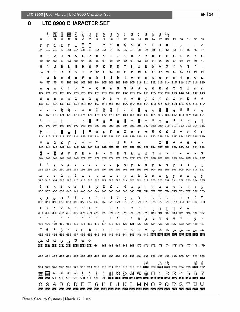
EN | 24LTC 8900 | User Manual | LTC 8900 Character Set
8 LTC 8900 CHARACTER SET
Bosch Security Systems | March 17, 2009
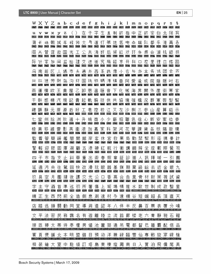
EN | 25LTC 8900 | User Manual | Character Set
Bosch Security Systems | March 17, 2009

EN | 26LTC 8900 | User Manual | Character Set
Bosch Security Systems | March 17, 2009

LTC 8900 | User Manual | LTC 8900 Character Set EN | 27
Bosch Security Systems | March 17, 2009

LTC 8900 | User Manual | LTC 8900 Character Set EN | 28
Bosch Security Systems | March 17, 2009

LTC 8900 | User Manual | LTC 8900 Character Set EN | 29
Bosch Security Systems | March 17, 2009

LTC 8900 | User Manual | LTC 8900 Character Set EN | 30
Bosch Security Systems | March 17, 2009

EN | 31LTC 8900 | User Manual | Error Messages
Bosch Security Systems | March 17, 2009
9 ERROR MESSAGES
Error Description Error Description
Error 01 -
Invalid camera request
The camera number entered from thekeyboard does not exist. If using the LTC 8059/00 MCS or the LTC 8850/00GUI software, ensure that the numberexists in the Camera Identification table.Download the table to be sure.
Error 20 -
Acknowledge denied
ACKNOWLEDGE has beenpressed by a user without authorityto acknowledge alarms.
Error 02 -
Invalid monitor request
The monitor number entered from thekeyboard does not exist. Enter a validmonitor number.
Error 21 -
Incorrect acknowledge
To properly acknowledge an alarmevent, the keyboard must beswitched to a monitor that isdisplaying the alarms.
Error 03 -
Locked remote device
The remote device requested cannot becontrolled because it is locked by a userwith equal or higher priority. Check withthe other users or request that a higherpriority user unlock the remote device.
Error 22 -
Acknowledge disabled
Alarms on this monitor cannot beacknowledged because thatcapability has been disabled by thesystem programmer.
Error 04 -
Monitor locked
The monitor requested cannot be accessedbecause it is locked by a user with equal orhigher priority. Check with the other usersor request that a higher priority userunlock the monitor.
Error 23 -
Camera not in alarm
The camera displayed on themonitor is not an alarm video;only alarm-generated video can beacknowledged.
Error 05 -
Remote device
access restricted
Remote is locked out by Remote Lock Outtable.
Error 24 -
Keyboard not enabled for
acknowledge
This keyboard may notacknowledge alarm video on thismonitor; it has been disabled bythe system programmer.
Error 06 -
Monitor access
restricted
Monitor is locked out by Monitor LockOut Table.
Error 25 -
Alarm switcher running
Alarm video may only beacknowledged if the alarm switcheris not running; press HOLD tostop the switcher.
Error 10 -
Access denied
A function was requested that requires ahigher user priority. Only a priority 2 useror a supervisor with priority 1 may accessthis function.
Error 50 -
SEQUENCE not available
Error 51 -
SEQUENCE not available
The user tried to load a switchersequence that does not exist. Thisis a good way to tell from thekeyboard, which sequencenumbers are unused when desiringto add one.
A request was made to load anABSOLUTE sequence without thekeyboard being on one of themonitors in that sequence. Becauseinadvertent loading of monitorsshould be avoided, the user isrequired to switch his keyboard toone of the monitors used by thesequence. The PROGRAM modemay be used to review whichmonitors are used in the sequence.
Error 11 -
Access denied
A function was requested for which youruser priority is too low. Only a supervisorwith priority 1 may access this function.
Error 52 -
SEQUENCE request
A request was made to load aRELATIVE sequence on amonitor number that is too high.The monitors used by the sequencewould extend past the highestmonitor. Try switching to a lowermonitor number before loading thesequence.
Error 15 -
Invalid user function
The function number requested from thekeyboard is invalid. Refer to the UserFunction table for a listing of the valid userfunction numbers.
Error 53 -
Switcher empty
The user has tried to control asequence using NEXT, PREV,RUN, or HOLD without asequence having been loaded.
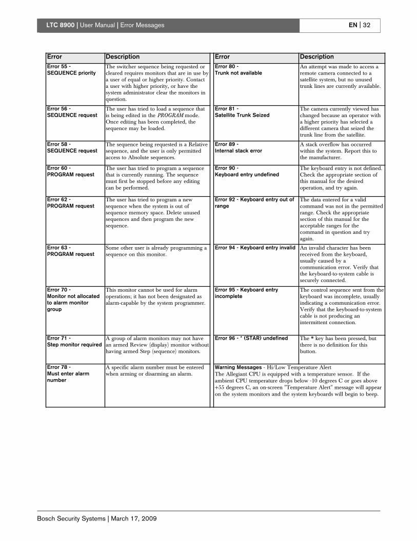
EN | 32LTC 8900 | User Manual | Error Messages
Bosch Security Systems | March 17, 2009
Error Description Error Description
Error 55 -
SEQUENCE priority
The switcher sequence being requested orcleared requires monitors that are in use bya user of equal or higher priority. Contacta user with higher priority, or have thesystem administrator clear the monitors inquestion.
Error 80 -
Trunk not available
An attempt was made to access aremote camera connected to asatellite system, but no unusedtrunk lines are currently available.
Error 56 -
SEQUENCE request
The user has tried to load a sequence thatis being edited in the PROGRAM mode.Once editing has been completed, thesequence may be loaded.
Error 81 -
Satellite Trunk Seized
The camera currently viewed haschanged because an operator witha higher priority has selected adifferent camera that seized thetrunk line from the satellite.
Error 58 -
SEQUENCE request
The sequence being requested is a Relativesequence, and the user is only permittedaccess to Absolute sequences.
Error 89 -
Internal stack error
A stack overflow has occurredwithin the system. Report this tothe manufacturer.
Error 60 -
PROGRAM request
The user has tried to program a sequencethat is currently running. The sequencemust first be stopped before any editingcan be performed.
Error 90 -
Keyboard entry undefined
The keyboard entry is not defined.Check the appropriate section ofthis manual for the desiredoperation, and try again.
Error 62 -
PROGRAM request
The user has tried to program a newsequence when the system is out ofsequence memory space. Delete unusedsequences and then program the newsequence.
Error 92 - Keyboard entry out of
range
The data entered for a validcommand was not in the permittedrange. Check the appropriatesection of this manual for theacceptable ranges for thecommand in question and tryagain.
Error 63 -
PROGRAM request
Some other user is already programming asequence on this monitor.
Error 94 - Keyboard entry invalid An invalid character has beenreceived from the keyboard,usually caused by acommunication error. Verify thatthe keyboard-to-system cable issecurely connected.
Error 70 -
Monitor not allocated
to alarm monitor
group
This monitor cannot be used for alarmoperations; it has not been designated asalarm-capable by the system programmer.
Error 95 - Keyboard entry
incomplete
The control sequence sent from thekeyboard was incomplete, usuallyindicating a communication error.Verify that the keyboard-to-systemcable is not producing anintermittent connection.
Error 71 -
Step monitor required
A group of alarm monitors may not havean armed Review (display) monitor withouthaving armed Step (sequence) monitors.
Error 96 - * (STAR) undefined The * key has been pressed, butthere is no definition for thisbutton.
Error 78 -
Must enter alarm
number
A specific alarm number must be enteredwhen arming or disarming an alarm.
Warning Messages - Hi/Low Temperature AlertThe Allegiant CPU is equipped with a temperature sensor. If theambient CPU temperature drops below -10 degrees C or goes above+55 degrees C, an on-screen "Temperature Alert" message will appearon the system monitors and the system keyboards will begin to beep.

EN | 33
Bosch Security Systems | March 17, 2009
LTC 8900 | User Manual | Glossary of Terms
10 GLOSSARY OF TERMS
Term Definition
AUXILIARY An auxiliary is an additional function of the remote receiver/driver, which permits on/off control of outputs
available to the user. In the Allegiant system, four relay outputs are available, which can be configured for
contact closures, 24VAC output, or LINE voltage output. Additionally, they can be set to activate either
momentarily, or in a latching mode.
COMMAND SCRIPT A unique feature of the Allegiant system wherein a section of nonvolatile memory can be used to store
specialized factory programming. This program then provides custom features, not ordinarily obtainable.
DITHER A receiver/driver feature providing added protection to very low light level cameras, by periodically panning
a few degrees to the left and right automatically.
LOCKOUTS Switcher/controller system ability to restrict access to certain system functions/features. The Allegiant
system modes of lockout are:
By operator level, allowing a higher priority level operator to lock out lower level operators from
viewing or controlling specific cameras.
By MCS setups to:
1. Restrict operators/keyboards from viewing/accessing any camera.
2. Restrict operators/keyboards from controlling/accessing any pan/tilt.
3. Restrict operators from using certain keyboards.
4. Restrict operators/keyboards from accessing certain monitors.
LOGON, LOGOFF A selectable Allegiant feature requiring operators to enter a User number and optional password into the
keyboard prior to access.
MATRIX SWITCHING The ability of a switching system to display any camera on any monitor, or the same camera on all monitors.
PHASED CAMERAS These are properly integrated cameras, giving a roll-free video display when switching from one camera to
the next in a sequential switcher system. Phased cameras are the result of line-locked cameras powered
from the same AC power, externally synchronized, or vertically phase adjusted on cameras equipped with
this option.
PRE-POSITION The ability to store the position of a pan/tilt/zoom lens, so that the desired scene can later be automatically
recalled. With the Allegiant system, multiple preset scenes can be stored for each pan/tilt camera. For each
scene, the pan, tilt, zoom, and focus settings are stored.
SalvoSwitching The ability of the Allegiant system to switch multiple video monitors as a synchronized group. Since multiple
monitors switch together, multiple scenes of an area or zone are viewable before switching to the next area.
SEQUENCE A series of camera scenes that can be preprogrammed to switch automatically. The Allegiant system can
store up to 60 sequences, each one capable of having random camera order, individual camera dwell
times, and SalvoSwitching steps.
TIME EVENT An Allegiant system feature (available with the LTC 8059/00 MCS for Windows or the LTC 8850/00 GUI
software) enabling various system functions to periodically be activated automatically. Event functions
(monitor message broadcasts, sequence and switching operations, receiver/driver actions, message
printing, alarm settings, and execution of custom factory programming) can be stored in the system memory
for execution at a predetermined time. The task can be specified to begin on a specific year, month, day,
and time, and can repeat at intervals from every five minutes to yearly.
VERTICAL INTERVAL
SWITCHING
Camera to camera video switching during the vertical blanking interval of the video signal. This minimizes
visual switching disturbances such as rolling, jitter, video flashes, etc., and eliminates frame information loss
when used with video tape machines.

EN | 34LTC 8900 | User Manual |
Bosch Security Systems | March 17, 2009

EN | 35LTC 8900 | User Manual |
Bosch Security Systems | March 17, 2009

2009 Bosch Security Systems, Inc.
F01U127363 09-03 | Updated March 17, 2009 | Data subject to change without notice.
AAmmeerriiccaass
BBoosscchh SSeeccuurriittyy SSyysstteemmss,, IInncc..
850 Greenfield Road
Lancaster, Pennsylvania 17601
USA
Telephone +1 888-289-0096
Fax +1 585-223-9180
Email: [email protected]
www.boschsecurity.us
EEuurrooppee,, MMiiddddllee EEaasstt,, AAffrriiccaa::
BBoosscchh SSeeccuurriittyy SSyysstteemmss BB..VV..
P.O. Box 80002
5600 JB Eindhoven, The Netherlands
Phone: + 31 40 2577 284
Fax: +31 40 2577 330
www.boschsecurity.com
AAssiiaa--PPaacciiffiicc::
BBoosscchh SSeeccuurriittyy SSyysstteemmss PPttee LLttdd
38C Jalan Pemimpin
Singapore 577180
Phone: +65 6319 3450
Fax: +65 6319 3499
www.boschsecurity.com