lte demonstration network test plan phase 3 part_1-v2_4_05072013
TRANSCRIPT
1
Public Safety Communications Research
LTE Demonstration Network Test Plan
Phase 3 Part 1: Network Interoperability & Drive Test
Version 2.4
May 7, 2013

2
1 Contents 2 List of Tables ........................................................................................................................................ 5
3 List of Figures ....................................................................................................................................... 5
4 Introduction ......................................................................................................................................... 5
5 Network Interoperability ..................................................................................................................... 7
5.1 Network Element Under Test: eNB (with Cisco EPC) ................................................................... 8
5.1.1 Test Description ................................................................................................................... 8
5.1.2 Reference ............................................................................................................................. 8
5.1.3 Required Equipment ............................................................................................................ 8
5.1.4 Test Procedure ..................................................................................................................... 9
5.1.5 Expected Outcome ............................................................................................................... 9
5.1.6 Additional Tests ................................................................................................................... 9
5.2 Network Element Under Test: eNB (with ALU EPC) ..................................................................... 9
5.2.1 Test Description ................................................................................................................... 9
5.2.2 Reference ............................................................................................................................. 9
5.2.3 Required Equipment ............................................................................................................ 9
5.2.4 Test Procedure ................................................................................................................... 10
5.3 Network Element Under Test: eNB (with General Dynamics Broadband EPC) ......................... 10
5.3.1 Test Description ................................................................................................................. 10
5.3.2 Reference ........................................................................................................................... 10
5.3.3 Required Equipment .......................................................................................................... 10
5.3.4 Test Procedure ................................................................................................................... 11
5.4 Network Element Under Test: eNB (with MSI Solutions/Ericsson EPC) ..................................... 11
5.4.1 Test Description ................................................................................................................. 11
5.4.2 Reference ........................................................................................................................... 11
5.4.3 Required Equipment .......................................................................................................... 11
5.4.4 Test Procedure ................................................................................................................... 12
5.5 Network Element Under Test: eNB (with NSN/Harris EPC) ....................................................... 12
5.5.1 Test Description ................................................................................................................. 12
5.5.2 Reference ........................................................................................................................... 12
5.5.3 Required Equipment .......................................................................................................... 12
5.5.4 Test Procedure ................................................................................................................... 13

3
6 Network Drive Testing ....................................................................................................................... 13
6.1 Additional Considerations .......................................................................................................... 14
6.2 Single User Throughput: UL UDP; No Load ................................................................................ 15
6.2.1 Test Description ................................................................................................................. 15
6.2.2 Reference ........................................................................................................................... 15
6.2.3 Required Equipment .......................................................................................................... 15
6.2.4 Test Procedure ................................................................................................................... 16
6.2.5 Expected Outcome ............................................................................................................. 16
6.3 Single User Throughput: DL UDP; No Load ................................................................................ 17
6.3.1 Test Description ................................................................................................................. 17
6.3.2 Reference ........................................................................................................................... 17
6.3.3 Required Equipment .......................................................................................................... 17
6.3.4 Test Procedure ................................................................................................................... 17
6.3.5 Expected Outcome ............................................................................................................. 18
6.4 Single User Throughput: UL TCP; No Load ................................................................................ 19
6.5 Single User Throughput: DL TCP; No Load ................................................................................ 19
6.6 Single User Throughput: UL UDP; 70% Load .............................................................................. 19
6.6.1 Test Description ................................................................................................................. 19
6.6.2 Reference ........................................................................................................................... 19
6.6.3 Required Equipment .......................................................................................................... 19
6.6.4 Test Procedure ................................................................................................................... 20
6.6.5 Expected Outcome ............................................................................................................. 20
6.7 Single User Throughput: DL UDP; 70% Load .............................................................................. 21
6.7.1 Test Description ................................................................................................................. 21
6.7.2 Reference ........................................................................................................................... 21
6.7.3 Required Equipment .......................................................................................................... 21
6.7.4 Test Procedure ................................................................................................................... 21
6.7.5 Expected Outcome ............................................................................................................. 22
6.8 Single User Throughput: UL TCP; 70% Load .............................................................................. 23
6.9 Single User Throughput: DL TCP; 70% Load .............................................................................. 23
6.10 Multi-‐User Throughput: UL UDP; No Load ................................................................................ 23
6.10.1 Test Description ................................................................................................................. 23
4
6.10.2 Reference ........................................................................................................................... 23
6.10.3 Required Equipment .......................................................................................................... 23
6.10.4 Test Procedure ................................................................................................................... 23
6.10.5 Expected Outcome ............................................................................................................. 24
6.11 Multi-‐User Throughput: DL UDP; No Load ................................................................................ 25
6.11.1 Test Description ................................................................................................................. 25
6.11.2 Reference ........................................................................................................................... 25
6.11.3 Required Equipment .......................................................................................................... 25
6.11.4 Test Procedure ................................................................................................................... 25
6.11.5 Expected Outcome ............................................................................................................. 26
6.12 Multi-‐User Throughput: UL TCP; No Load .................................................................................. 27
6.13 Multi-‐User Throughput: DL TCP: No Load .................................................................................. 27
6.14 Multi-‐User Throughput: UL UDP; 70% Load .............................................................................. 27
6.14.1 Test Description ................................................................................................................. 27
6.14.2 Reference ........................................................................................................................... 28
6.14.3 Required Equipment .......................................................................................................... 28
6.14.4 Test Procedure ................................................................................................................... 28
6.14.5 Expected Outcome ............................................................................................................. 29
6.15 Multi-‐User Throughput: DL UDP: 70% Load .............................................................................. 29
6.15.1 Test Description ................................................................................................................. 29
6.15.2 Reference ........................................................................................................................... 30
6.15.3 Required Equipment .......................................................................................................... 30
6.15.4 Test Procedure ................................................................................................................... 30
6.15.5 Expected Outcome ............................................................................................................. 31
6.16 Multi-‐User Throughput: UL TCP; 70% Load ............................................................................... 31
6.17 Multi-‐User Throughput: DL TCP: 70% Load ............................................................................... 31
6.18 Network Latency: Single User; No Load ..................................................................................... 31
6.18.1 Test Description ................................................................................................................. 31
6.18.2 Reference ........................................................................................................................... 32
6.18.3 Required Equipment .......................................................................................................... 32
6.18.4 Test Procedure ................................................................................................................... 32
6.18.5 Expected Outcome ............................................................................................................. 32

5
6.19 Network Latency: Single User; 70% Load ................................................................................... 33
7 UE Interoperability Tests ................................................................................................................... 33
8 Vendor Test Case Checklist ................................................................................................................ 33
9 Acronyms ........................................................................................................................................... 35
10 Optional Information and Tests ..................................................................................................... 35
10.1 Extra IOT Information ................................................................................................................ 35
10.1.1 Verify Message Flow .......................................................................................................... 35
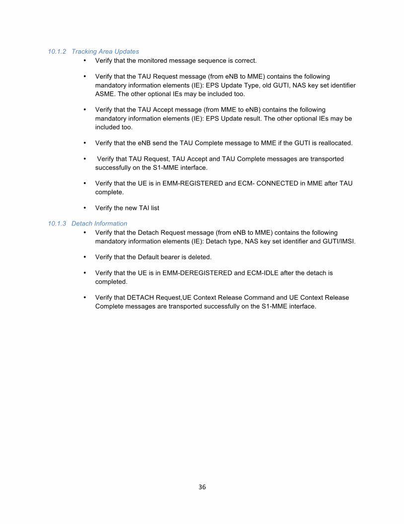
10.1.2 Tracking Area Updates ....................................................................................................... 36
10.1.3 Detach Information ............................................................................................................ 36
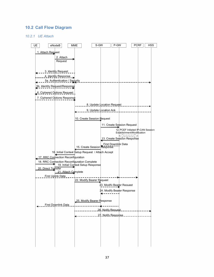
10.2 Call Flow Diagram ...................................................................................................................... 37
10.2.1 UE Attach ........................................................................................................................... 37
10.2.2 TAU UE Call Flow ................................................................................................................ 38
10.2.3 UE Detach Call Flow ........................................................................................................... 38
2 List of Tables Table 1: Vendor Test Case Checklist ..................................................................................................... 3433
3 List of Figures Figure 1: Test Diagram ................................................................................. Error! Bookmark not defined.8
4 Introduction
Public Safety Communications Research (PSCR) has established three major phases of testing and evaluation. The primary focus of Phase 3 Part 1 is to test LTE infrastructure for interoperability and to drive test each vendor’s implementation. Phase 3 Part 2 will focus on EPC interface conformance testing. It should be noted that PSCR reserves the right to add additional phases (beyond the three currently defined) of testing at any time. An example of the type of tests that would be encountered in later phases is multiple EPS handover within a PLMN utilizing the S5 and S10 interfaces.

6
If time allows further IOT may be performed in Phase 3 Part 1 that involves other EPC components. Several vendors are utilizing EPC components manufactured by different vendors and are already performing multi-‐vendor interworking involving the S6a and Gx interfaces. All vendors will be notified in advance of the addition of new interoperability tests to Phase 3 Part 1 and will be given an opportunity to review and comment on any new tests before they are executed in the PSCR laboratory. Interoperability Tests: The primary focus of interoperability testing in the PSCR demonstration network is to evaluate how different vendor’s EPC and RAN interact with each other. Specifically, the interoperability section of this document considers a configuration where a given vendor’s eNB is integrated with another vendor’s EPC. Specific scenarios are then executed against each configuration. See Section 5 of this test plan for more details. A secondary focus of interoperability testing in the demonstration network is to evaluate a given vendor’s UE against several other eNB implementations. This evaluation will be performed according the UE IOT test plan created by CTIA. http://files.ctia.org/pdf/CTIA_LTE_IOT_Test_Plan_Rev_1.0.pdf Network Drive Tests: The purpose of network drive testing is to evaluate the coverage and performance of a network with at least one active data session established. The network in this case will consist of RAN and EPC equipment provided by the same vendor. The set of drive tests in Section 6 will be conducted against each vendor that is providing a RAN and an EPC to the demonstration network. In order to accommodate those vendors who are only supplying an EPC, PSCR will help to put the EPC vendor in contact with a RAN vendor (or vendors) so that drive testing may be conducted which utilizes the vendor’s EPC. See Section 6 of this test plan for more detailed information. Additional Information:
1) Results of all Phase 3 tests will be recorded as either executed or not executed unless otherwise stated.
2) It is possible that Phase 3 Part 2 tests could pre-‐empt Phase 3 Part 1 testing as conformance test events are scheduled. When this occurs, Phase 3 Part 1 tests will be halted for a period of two to three weeks to allow for the scheduled conformance test event to complete. All parties will be notified in advanced of a scheduled test event. Refer to the Phase 3 Part 2 test plan for detailed information regarding how EPC conformance testing will be handled in the PSCR demonstration network.
3) For network driving testing, PSCR staff will drive test a pre-‐defined route, log data, and analyze the collected data. The vendor(s) will help support the driving test effort by providing personnel to help with troubleshooting the infrastructure (or the UE) and to help with the operations and maintenance of the infrastructure.

7
4) For all tests in this test plan, PSCR will use the JDSU SART tool that it currently owns for performing monitoring of the EPC core interfaces. In addition, for the monitoring of the Uu interface PSCR will use the Linkmaster and drive test software, which it currently owns. A tap point will be provided in order for vendors to perform monitoring, troubleshooting, and message logging of the traffic on the EPC interfaces using their preferred monitoring tool (e.g. Wireshark).
5) As additional clarification, all eNBs will use GPS for their timing reference. 6) All networks should be upgraded to 3GPP Release 9 (December 2009 Phase 3 Freeze) prior to
testing.
5 Network Interoperability
This section of the test plan will focus on three basic scenarios in order to evaluate LTE infrastructure for interoperability. These scenarios will be used to exercise as many of the EPC interfaces as possible along with the Uu interface. The scenarios and the interfaces each scenario exercises are listed below:
1) UE Attach – Uu, S1, S6a
2) UE Detach – Uu, S1, S6a
3) Data Session Establishment – Uu, S1, S1-‐U, S11, S5, Gx
The scenarios listed above will drive the interoperability test cases. Each test case will focus on varying a single network element while holding all other network elements in the LTE system constant. The list of LTE network elements to be varied is as follows:
1) eNB
A vendor’s EPC (vendor X) will be selected and the network elements that compose the EPC will be held constant. The eNB will be the network element under test. For example, an eNB’s supplied by vendor A will be integrated with vendor X’s EPC. The three scenarios listed above will then be executed using a single eNB from vendor A and vendor X’s EPC. The three scenarios listed above will then be executed using a single eNB from vendor B and vendor X’s EPC. This process will be repeated until all three scenarios listed above have been executed against all eNBs in the PSCR laboratory utilizing vendor X’s EPC.
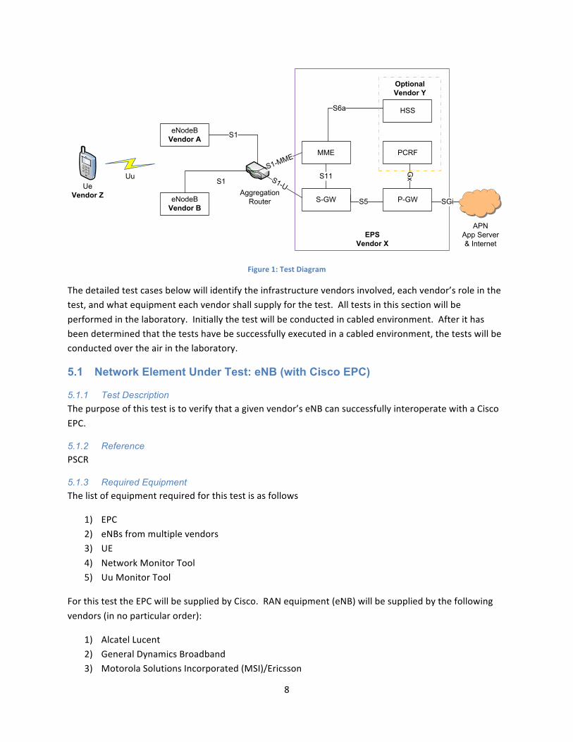
8
UeVendor Z P-GWS-GW
MME PCRF
HSSS6a
eNodeBVendor A
AggregationRouter
S1-MME
S1-U
S1
Uu
S5
S11
Gx
eNodeBVendor B
S1
EPSVendor X
Optional Vendor Y
SGi
APNApp Server & Internet
Figure 1: Test Diagram
The detailed test cases below will identify the infrastructure vendors involved, each vendor’s role in the test, and what equipment each vendor shall supply for the test. All tests in this section will be performed in the laboratory. Initially the test will be conducted in cabled environment. After it has been determined that the tests have be successfully executed in a cabled environment, the tests will be conducted over the air in the laboratory.
5.1 Network Element Under Test: eNB (with Cisco EPC)
5.1.1 Test Description The purpose of this test is to verify that a given vendor’s eNB can successfully interoperate with a Cisco EPC.
5.1.2 Reference PSCR
5.1.3 Required Equipment The list of equipment required for this test is as follows
1) EPC 2) eNBs from multiple vendors 3) UE 4) Network Monitor Tool 5) Uu Monitor Tool
For this test the EPC will be supplied by Cisco. RAN equipment (eNB) will be supplied by the following vendors (in no particular order):
1) Alcatel Lucent 2) General Dynamics Broadband 3) Motorola Solutions Incorporated (MSI)/Ericsson

9
4) Nokia Siemens Networks (NSN)/Harris
The UE will be a MSI UM 1000 USB Dongle.
5.1.4 Test Procedure 1) Integrate the Alcatel Lucent eNB with the Cisco EPC. 2) Turn on the message tracing capability in the eNB and MME for troubleshooting purposes. 3) Mirror all EPC interfaces in the Cisco EPC to a monitor port. This will be used for
troubleshooting purposes. 4) Connect the monitor port to the network-‐monitoring tool. 5) Provision the MSI in the Cisco HSS. 6) Program the UE SIM card with the correct IMSI and Ki values. 7) Connect the UE dongle to a laptop that contains the appropriate connection manager software
and that contains the Uu monitor software. 8) Perform a UE Attach by turning on the UE. 9) Establish a data session by utilizing the connection manager software and browsing to
www.pscr.gov. 10) Perform a UE Detach by clicking “Disconnect” on the connection manager. 11) Repeat steps 1 – 10 for the eNBs supplied by General Dynamics Broadband, MSI, and
NSN/Harris.
5.1.5 Expected Outcome Verify that the UE attached, a data session was established, and that the UE detached.
See Appendix of optional information that may be captured during the testing.
5.1.6 Additional Tests Repeat section 5.1.1-‐5.1.5 with the Thales EPC
5.2 Network Element Under Test: eNB (with ALU EPC)
5.2.1 Test Description The purpose of this test is to verify that a given vendor’s eNB can successfully interoperate with an Alcatel Lucent EPC.
5.2.2 Reference PSCR
5.2.3 Required Equipment The list of equipment required for this test is as follows
1) EPC 2) eNBs from multiple vendors 3) UE 4) Network Monitor Tool
10
5) Uu Monitor Tool
For this test Alcatel Lucent will supply the EPC. RAN equipment (eNB) will be supplied by the following vendors:
1) General Dynamics Broadband 2) MSI 3) NSN/Harris
The UE will be supplied by MSI.
5.2.4 Test Procedure 1) Integrate the General Dynamics Broadband eNB with the Alcatel Lucent EPC. 2) Turn on the message tracing capability in the eNB and MME for troubleshooting purposes. 3) Mirror all EPC interfaces in the Alcatel Lucent EPC to a monitor port. This will be used for
troubleshooting purposes. 4) Connect the monitor port to the network-‐monitoring tool. 5) Provision the MSI in the Alcatel Lucent HSS. 6) Program the UE SIM card with the correct IMSI and Ki values. 7) Connect the UE dongle to a laptop that contains the appropriate connection manager software
and that contains the Uu monitor software. 8) Perform a UE Attach by turning on the UE. 9) Establish a data session by utilizing the connection manager software and browsing to
www.pscr.gov. 10) Perform a UE Detach by clicking “Disconnect” on the connection manager. 11) Repeat steps 1 – 10 for the eNBs supplied by MSI Solutions/Ericsson and NSN/Harris.
5.3 Network Element Under Test: eNB (with General Dynamics Broadband EPC)
5.3.1 Test Description The purpose of this test is to verify that a given vendor’s eNB can successfully interoperate with a General Dynamics Broadband EPC.
5.3.2 Reference PSCR
5.3.3 Required Equipment The list of equipment required for this test is as follows
1) EPC 2) eNBs from multiple vendors 3) UE 4) Network Monitor Tool
11
5) Uu Monitor Tool
For this test General Dynamics Broadband will supply the EPC. RAN equipment (eNB) will be supplied by the following vendors:
1) Alcatel Lucent 2) MSI 3) NSN/Harris
The UE will be a MSI UM 1000 USB Dongle
5.3.4 Test Procedure 1) Integrate the Alcatel Lucent eNB with the General Dynamics Broadband EPC. 2) Turn on the message tracing capability in the eNB and MME for troubleshooting purposes. 3) Mirror all EPC interfaces in the General Dynamics Broadband EPC to a monitor port. This will be
used for troubleshooting purposes. 4) Connect the monitor port to the network-‐monitoring tool. 5) Provision the MSI in the General Dynamics Broadband HSS. 6) Program the UE SIM card with the correct IMSI and Ki values. 7) Connect the UE dongle to a laptop that contains the appropriate connection manager software
and that contains the Uu monitor software. 8) Perform a UE Attach by turning on the UE. 9) Establish a data session by utilizing the connection manager software and browsing to
www.pscr.gov. 10) Perform a UE Detach by clicking “Disconnect” on the connection manager. 11) Repeat steps 1 – 10 for the eNBs supplied by MSI Solutions/Ericsson and NSN/Harris.
5.4 Network Element Under Test: eNB (with MSI Solutions/Ericsson EPC)
5.4.1 Test Description The purpose of this test is to verify that a given vendor’s eNB can successfully interoperate with a MSI Solutions/Ericsson EPC.
5.4.2 Reference PSCR
5.4.3 Required Equipment The list of equipment required for this test is as follows
1) EPC 2) eNBs from multiple vendors 3) UE 4) Network Monitor Tool 5) Uu Monitor Tool

12
For this test the EPC will be supplied by MSI. RAN equipment (eNB) will be supplied by the following vendors:
1) Alcatel Lucent 2) General Dynamics Broadband 3) NSN/Harris
The UE will be a MSI UM 1000 USB Dongle
5.4.4 Test Procedure 1) Integrate the Alcatel Lucent eNB with the MSI Solutions. 2) Turn on the message tracing capability in the eNB and MME for troubleshooting purposes. 3) Mirror all EPC interfaces in the MSI Solutions to a monitor port. This will be used for
troubleshooting purposes. 4) Connect the monitor port to the network-‐monitoring tool. 5) Provision the MSI in the MSI HSS. 6) Program the UE SIM card with the correct IMSI and Ki values. 7) Connect the UE dongle to a laptop that contains the appropriate connection manager software
and that contains the Uu monitor software. 8) Perform a UE Attach by turning on the UE. 9) Establish a data session by utilizing the connection manager software and browsing to
www.pscr.gov. 10) Perform a UE Detach by clicking “Disconnect” on the connection manager. 11) Repeat steps 1 – 10 for the eNBs supplied by General Dynamics Broadband and NSN/Harris.
5.5 Network Element Under Test: eNB (with NSN/Harris EPC)
5.5.1 Test Description The purpose of this test is to verify that a given vendor’s eNB can successfully interoperate with a NSN/Harris EPC.
5.5.2 Reference PSCR
5.5.3 Required Equipment The list of equipment required for this test is as follows
1) EPC 2) eNBs from multiple vendors 3) UE 4) Network Monitor Tool 5) Uu Monitor Tool
13
For this test NSN/Harris will supply the EPC. RAN equipment (eNB) will be supplied by the following vendors:
1) Alcatel Lucent 2) General Dynamics Broadband 3) MSI
The UE will be a MSI UM 1000 USB Dongle.
5.5.4 Test Procedure 1) Integrate the Alcatel Lucent eNB with the NSN/Harris EPC. 2) Turn on the message tracing capability in the eNB and MME for troubleshooting purposes. 3) Mirror all EPC interfaces in the NSN/Harris EPC to a monitor port. This will be used for
troubleshooting purposes. 4) Connect the monitor port to the network-‐monitoring tool. 5) Provision the MSI in the NSN/Harris HSS. 6) Program the UE SIM card with the correct IMSI and Ki values. 7) Connect the UE dongle to a laptop that contains the appropriate connection manager software
and that contains the Uu monitor software. 8) Perform a UE Attach by turning on the UE. 9) Establish a data session by utilizing the connection manager software and browsing to
www.pscr.gov. 10) Perform a UE Detach by clicking “Disconnect” on the connection manager. 11) Repeat steps 1 – 10 for the eNBs supplied by General Dynamics Broadband and MSI.
6 Network Drive Testing The purpose of network drive testing is to evaluate the performance of a single LTE network in an operational environment. All tests will be conducted in the field against each infrastructure vendor’s system.
The tests contained in this section have been designed to expand on the tests that were written into PSCR Phase 1 and Phase 2. These phases contained a limited amount of over the air network performance tests along with extensive throughput testing in a laboratory environment. The objective of the tests in this section is to test the LTE system (infrastructure and UEs) in an operational environment.
Keeping consistent with PSCR’s methodology of leveraging industry accepted techniques for testing, PSCR’s drive testing and network evaluation is based upon some of the testing concepts presented in the JDSU application note titled “LTE and EPC Test An Overview of Test Concepts and Tools for Trials”. 1 The testing concepts presented in the application note have been modified to fit the needs of PSCR.
1 http://www.jdsu.com/NoIndexLiterature/lte_test_appnote.pdf
14
Additionally the GSMA TS112, Annex C document has been significantly utilized in multiple sections of this document.
The major areas PSCR will be focusing its testing efforts on are:
1) Single User Throughput
2) Intra-‐LTE Handover
3) Network Latency
PSCR will establish a single drive route that all vendor systems will be evaluated against. For all test cases in this section, PSCR will log data along this route using a drive test-‐logging tool such as the Anritsu Link Master or JDSU E6474A drive test software. The data will then be post processed and analyzed by PSCR.
The drive test software contains a “sequencer” function. The purpose of the function is to automate the use of various applications during drive testing. For example, the end user can configure the sequencer to serially run an FTP session followed by an IPERF session then followed by a Web Browsing session. Upon completion of the Web Browsing session the sequence will be repeated starting with the establishment of an FTP session.
Network load will utilize OFDMA Channel Noise Generator (OCNG)3 as implemented by vendors within their RAN for downlink (DL) load. Investigation is ongoing if uplink (UL) loading can be accomplished in a controlled manner for drive testing. If possible -‐ use of 3GPP-‐C1 simulation for 70% loading may be used for the UL loading tests.
6.1 Additional Considerations
1) For all tests in this section, the desire is to test handovers, either S1 or X2 . Vendor assistance on configuring the tests will be necessary. These tests will initially use the default bearer (dedicated bearer will be run in Phase 2). Testing will encompass intra eNB handover and inter eNB based handover. Handovers will be run in same and adjacent cell loaded and unloaded conditions. The methodology for X2 and S1 should be the same.
2) The UE should perform handovers as requested by the network, and behave as expected from the user perspective without losing services.
3) There must be a sufficient number of E-‐UTRA cells available on the same PLMN. Required packet bearers to be tested should be active, and available in all parts of the test route.
4) The test route(s) should contain the handoff zones to allow for E-‐UTRA handover, intra eNodeB handover, and if system provisioning allows inter-‐MME handover.
2 http://www.gsma.com/newsroom/technical-‐documents/ 3 OCNG as per 3GPP TS 36.521, Appendix 5
15
5) It shall be ensured that the UE performs reselections/handovers as expected. During the test drive it is imperative the UE remains in service at all times, that the packet bearer in question is maintained throughout the test route and that the data download and upload is resumed correctly.
6) All UE and EPC data will be logged for control and user plane. 7) Use of iperf is recommended for initial testing and further tests utilizing video and voice
applications should be considered. The UE should perform handovers correctly, without losing service, and its PDN connectivity should remain viable before and after the handovers.
8) The UE should successfully resume the FTP downloads after the handovers. 9) Metrics evaluated should include handover success rate, control plane handover
interruption time, user plane handover interruption time and packet loss/jitter.
6.2 Single User Throughput: UL UDP; No Load
6.2.1 Test Description The purpose of this test is to evaluate the behavior of single-‐user UL UDP throughput while driving the established PSCR drive route. In this test no load will be applied to the DL of any cell in the system. Based on the findings in Phase 1 testing, the UE will be configured to transmit the maximum amount of data each system’s UL can sustain.
The analysis of the resulting log files will also include determining the handover success rate and the dropped data session rate. The handover success rate is defined as the number of successful handovers divided by the total number of handovers performed. Handover in this context includes between cells (a.k.a. sectors) on a single site and between the cell of one site to a cell of another site.
A dropped data session in this context refers to a data session that was not properly terminated. The dropped data session rate is defined as the number of data sessions not properly terminated divided by the total number of data sessions.
The drive route will be driven 10 times (subsequent drives may not be necessary) in order to acquire enough data. Separate log files will be kept for each pass of the route.
6.2.2 Reference PSCR
6.2.3 Required Equipment 1) JDSU and Link Master drive test software, Scanner, SART
2) UE
3) Gladiator or Link Master post processor
4) An application server with iperf

16
6.2.4 Test Procedure 1) If necessary connect external mag mount antennas to UE
2) Connect UE to PC that contains drive test software. Alternatively, UE can be connected to USB ports on JDSU scanner.
3) Connect GPS antenna to JDSU scanner and Link Master drive test computer.
4) Start drive test software on PC and connect via connection manager.
5) Configure the drive test software sequencer to enable an iperf UDP session. The iperf UDP session will be terminated at the PSCR owned application server. The transfer of the iperf data must be from the UE to the eNB. The iperf composite stream must be configured to the maximum data rate the UL of the system under test can sustain.
6) Start logging data with the drive test software.
7) Attach UE to the network.
8) Start the sequencer in the drive test software. This will start the iperf application.
9) Drive pre-‐defined route.
10) After the entire route has been driven, stop logging on the drive test software.
11) Drive the pre-‐defined route nine more times.
12) Post-‐process the log files using the appropriate drive test software application.
13) Average UL throughput and pathloss over all 10 drives. Since the GPS coordinate values will not be the same for each drive a binning technique will have to be employed to create a single data set that can be overlaid on a map.
14) Analyze the data for UL throughput, handover success rate, handover delay time, and dropped data session rate.
15) NOTE: This test can be run at the same time as section “6.3 Single User Throughput: Downlink (DL) UDP; No Load” on two laptops with separate UE.
6.2.5 Expected Outcome 1) Plots will be created that show the following:
a. Overlay of the following parameters on drive route:
i. Average UL Throughput (Avg. UL Throughput vs. Location)
b. Average UL Throughput vs. Average Pathloss
17
2) Handover Success Rate calculated over all 10 drives
3) Handover Delay Time calculated over all 10 drives.
4) Dropped Data Session Rate calculated over all 10 drives.
6.3 Single User Throughput: DL UDP; No Load
6.3.1 Test Description The purpose of this test is to evaluate the behavior of single-‐user DL UDP throughput while driving the established PSCR drive route. In this test no load will be applied to the DL of any cell in the system. Based on the findings in Phase 1 testing, an application server that has iperf on it will be configured to transmit the maximum amount of data each system’s DL can sustain.
The analysis of the resulting log files will also include determining the handover success rate and the dropped data session rate. The handover success rate is defined as the number of successful handovers divided by the total number of handovers performed. Handover in this context includes between cells (a.k.a. sectors) on a single site and between the cell of one site to a cell of another site. A dropped data session in this context refers to a data session that was not properly terminated. The dropped data session rate is defined as the number of data sessions not properly terminated divided by the total number of data sessions.
The drive route will be driven 10 times (subsequent drives may not be necessary) in order to acquire enough data. Separate log files will be kept for each pass of the route.
6.3.2 Reference PSCR
6.3.3 Required Equipment 1) JDSU and Link Master drive test software, Scanner, SART
2) UE
3) UE drive test post processor
4) An application server with iperf
6.3.4 Test Procedure 1) If necessary connect external mag mount antennas to UE
2) Connect UE to PC that contains drive test software. Alternatively, UE can be connected to USB ports on JDSU scanner.
3) Connect GPS antenna to JDSU scanner and Link Master drive test computer.
4) Start drive test software on PC.

18
5) Configure the application server to enable an iperf UDP session. The iperf UDP session will be terminated at the PSCR owned application server. The transfer of the iperf data must be from the eNB to the UE. The iperf composite stream must be configured to the maximum data rate the DL of the system under test can sustain.
6) Start logging data with the drive test software.
7) Attach UE to the network.
8) Start the iperf session at the application server.
9) Drive pre-‐defined route.
10) After the entire route has been driven, stop logging on drive test software.
11) Drive the pre-‐defined route nine more times.
12) Post-‐process the log files using the UE drive test post processing application.
13) Average pathloss, DL throughput, DL SNR, and DL BLER over all 10 drives. Since the GPS coordinate values will not be the same for each drive a binning technique will have to be employed to create a single data set that can be overlaid on a map.
14) Analyze the data for pathloss, DL throughput, handover success rate, and dropped data session rate.
15) NOTE: This test can be run at the same time as section “6.2 Single User Throughput: UL UDP; No Load” on two laptops with separate UE.
6.3.5 Expected Outcome 1) Plots will be created that show the following:
a. Overlay of the following parameters on drive route:
i. Average DL Throughput (Avg. DL Throughput vs. Location)
b. Average DL Throughput vs. Average DL SNR
c. Average DL Throughput vs. Average DL BLER
d. Average DL Throughput vs. pathloss
2) Handover Success Rate calculated over all 10 drives.
3) Handover Delay Time calculated over all 10 drives.
4)
19
5) Dropped Data Session Rate calculated over all 10 drives.
6.4 Single User Throughput: UL TCP; No Load Repeat procedure for 6.2 UDP UL loading. Use TCP stream on iperf/netperf with multiple stream and TCP window size set for OS. NOTE: This test can be run at the same time as section “6.5 Single User Throughput: DL TCP; No Load” on two laptops with separate UE.
6.5 Single User Throughput: DL TCP; No Load Repeat procedure for 6.3 UDP DL loading. Use TCP stream on iperf/netperf with multiple stream and TCP window size set for OS. NOTE: This test can be run at the same time as section “6.4 Single User Throughput: UL TCP; No Load” on two laptops with separate UE.
6.6 Single User Throughput: UL UDP; 70% Load
6.6.1 Test Description The purpose of this test is to evaluate the behavior of single-‐user UL UDP throughput while driving the established PSCR drive route. In this test 70% load will be applied to the DL of all cells in the system.4 Based on the findings in Phase 1 testing, the UE will be configured to transmit the maximum amount of data each system’s UL can sustain.
The analysis of the resulting log files will also include determining the handover success rate and the dropped data session rate. The handover success rate is defined as the number of successful handovers divided by the total number of handovers performed. Handover in this context includes between cells (a.k.a. sectors) on a single site and between the cell of one site to a cell of another site. A dropped data session in this context refers to a data session that was not properly terminated. The dropped data session rate is defined as the number of data sessions not properly terminated divided by the total number of data sessions.
The drive route will be driven 10 times (subsequent drives may not be necessary) in order to acquire enough data. Separate log files will be kept for each pass of the route.
6.6.2 Reference PSCR
6.6.3 Required Equipment 1) JDSU and Link Master drive test software, Scanner, and SART
2) UE
3) UE drive test post processor
4) An application server with iperf
4 NOTE: If 70% uplink loading is possible via 3GPP-‐C1 simulation, this will be utilized also.
20
6.6.4 Test Procedure 1) Set OCNS to 70% on the DL of all cells in the network.
2) If necessary connect external mag mount antennas to UE
3) Connect UE to PC that contains JDSU drive test software. Alternatively, UE can be connected to USB ports on JDSU scanner.
4) Connect GPS antenna to JDSU scanner and Link Master drive test computer.
5) Start drive test software on PC.
6) Configure the drive test software sequencer to enable an iperf UDP session. The iperf UDP session will be terminated at the PSCR owned application server. The transfer of the iperf data must be from the UE to the eNB. The iperf composite stream must be configured to the maximum data rate the UL of the system under test can sustain.
7) Start logging data with the drive test software.
8) Attach UE to the network.
9) Start the sequencer in the drive test software. This will start the iperf application.
10) Drive pre-‐defined route.
11) After the entire route has been driven, stop logging on drive test software.
12) Drive the pre-‐defined route nine more times.
13) Post-‐process the log files using the UE drive test post processing application.
14) Average UL throughput and pathloss over all 10 drives. Since the GPS coordinate values will not be the same for each drive a binning technique will have to be employed to create a single data set that can be overlaid on a map.
15) Analyze the data for UL throughput, handover success rate, handover delay time, and dropped data session rate.
16) NOTE: This test can be run at the same time as section “6.7 Single User Throughput: DL UDP; 70% Load” on two laptops with separate UE.
6.6.5 Expected Outcome 1) Plots will be created that show the following:
a. Overlay of the following parameters on drive route:
i. Average UL Throughput (Avg. UL Throughput vs. Location)
21
b. Average UL Throughput vs. Average pathloss
2) Handover Success Rate calculated over all 10 drives.
3) Handover Delay Time calculated over all 10 drives.
4) Dropped Data Session Rate calculated over all 10 drives.
6.7 Single User Throughput: DL UDP; 70% Load
6.7.1 Test Description The purpose of this test is to evaluate the behavior of single-‐user DL UDP throughput while driving the established PSCR drive route. In this test 70% load will be applied to the DL of all cells in the system. Based on the findings in Phase 1 testing, the UE will be configured to transmit the maximum amount of data each system’s UL can sustain.
The analysis of the resulting log files will also include determining the handover success rate and the dropped data session rate. The handover success rate is defined as the number of successful handovers divided by the total number of handovers performed. Handover in this context includes between cells (a.k.a. sectors) on a single site and between the cell of one site to a cell of another site. A dropped data session in this context refers to a data session that was not properly terminated. The dropped data session rate is defined as the number of data sessions not properly terminated divided by the total number of data sessions.
The drive route will be driven 10 times (subsequent drives may not be necessary) in order to acquire enough data. Separate log files will be kept for each pass of the route.
6.7.2 Reference PSCR
6.7.3 Required Equipment 1) JDSU and Link Master drive test software, Scanner, and SART
2) UE
3) UE drive test post processor
4) An application server with iperf
6.7.4 Test Procedure 1) Set OCNS to 70% on the DL of all cells in the network.
2) If necessary connect external mag mount antennas to UE
3) Connect UE to PC that contains JDSU drive test software. Alternatively, UE can be connected to USB ports on JDSU scanner.
4) Connect GPS antenna to JDSU scanner and Link Master drive test computer.
22
5) Start drive test software on PC.
6) Configure the drive test software sequencer to enable an iperf UDP session. The iperf UDP session will be terminated at the PSCR owned application server. The transfer of the iperf data must be from the UE to the eNB. The iperf composite stream must be configured to the maximum data rate the UL of the system under test can sustain.
7) Start logging data with the drive test software.
8) Attach UE to the network.
9) Start the sequencer in the drive test software. This will start the iperf application.
10) Drive pre-‐defined route.
11) After the entire route has been driven, stop logging on drive test software.
12) Drive the pre-‐defined route nine more times.
13) Post-‐process the log files using the UE drive test post processing application.
14) Average UL throughput and pathloss over all 10 drives. Since the GPS coordinate values will not be the same for each drive a binning technique will have to be employed to create a single data set that can be overlaid on a map.
15) Analyze the data for UL throughput, handover success rate, handover delay time, and dropped data session rate.
17) NOTE: This test can be run at the same time as section “6.6 Single User Throughput: UL UDP; 70% Load” on two laptops with separate UE.
6.7.5 Expected Outcome 1) Plots will be created that show the following:
a. Overlay of the following parameters on drive route:
i. Average UL Throughput (Avg. UL Throughput vs. Location)
b. Average UL Throughput vs. Average pathloss
2) Handover Success Rate calculated over all 10 drives.
3) Handover Delay Time calculated over all 10 drives.
4) Dropped Data Session Rate calculated over all 10 drives.
23
6.8 Single User Throughput: UL TCP; 70% Load Repeat procedure for 6.6 UDP UL loading. Use TCP stream on iperf/netperf with multiple stream and TCP window size set for OS. NOTE: This test can be run at the same time as section “6.9 Single User Throughput: DL TCP; 70% Load” on two laptops with separate UE.
6.9 Single User Throughput: DL TCP; 70% Load Repeat procedure for 6.7 UDP DL loading. Use TCP stream on iperf/netperf with multiple stream and TCP window size set for OS. NOTE: This test can be run at the same time as section “6.8 Single User Throughput: UL TCP; 70% Load” on two laptops with separate UE.
6.10 Multi-User Throughput: UL UDP; No Load
6.10.1 Test Description The purpose of this test is to evaluate the behavior of multi-‐user UL UDP throughput while driving the established PSCR drive route. In this test no load will be applied to the DL of any cell in the system. Four UEs will be used to perform this test. Based on the findings in Phase 1 testing, each UE will initially be configured to transmit 25% of the maximum amount of data each system’s UL can sustain.
The analysis of the resulting log files will also include determining the handover success rate and the dropped data session rate. The handover success rate is defined as the number of successful handovers divided by the total number of handovers performed. Handover in this context includes between cells (a.k.a. sectors) on a single site and between the cell of one site to a cell of another site. A dropped data session in this context refers to a data session that was not properly terminated. The dropped data session rate is defined as the number of data sessions not properly terminated divided by the total number of data sessions.
The drive route will be driven 10 times (subsequent drives may not be necessary) in order to acquire enough data. Separate log files will be kept for each pass of the route.
6.10.2 Reference PSCR
6.10.3 Required Equipment 1) JDSU and Link Master drive test software, Scanner, and SART
2) Four UEs
3) UE drive test post processor
4) An application server with iperf
6.10.4 Test Procedure 1) If necessary connect external mag mount antennas to UE
2) Connect all four UEs to PC that contains drive test software. Alternatively, each UE can be connected to a USB port on JDSU scanner.

24
3) Connect GPS antenna to JDSU scanner and Link Master drive test computer.
4) Start drive test software on PC.
5) Configure the drive test software sequencer to enable four-‐iperf UDP session. The iperf UDP session will be terminated at the PSCR owned application server. The transfer of the iperf data must be from the UEs to the eNB. Each iperf composite stream must be configured to 25% of the maximum data rate the UL of the system under test can sustain.
6) Start logging data with the drive test software.
7) Attach UEs to the network.
8) Start the sequencer in the drive test software. This will start the iperf application.
9) Drive pre-‐defined route.
10) After the entire route has been driven, stop logging on drive test software.
11) Drive the pre-‐defined route nine more times.
12) Post-‐process the log files using the UE post processing application.
13) For each UE, average UL throughput and pathloss over all 10 drives. Since the GPS coordinate values will not be the same for each drive a binning technique will have to be employed to create a single data set that can be overlaid on a map.
14) Analyze the data for the average UL throughput, handover success rate, and dropped data session rate associated with each UE.
6.10.5 Expected Outcome 1) For all four UEs, plots will be created that show the following:
a. Overlay of the following parameters on drive route:
i. Average UL Throughput (Avg. UL Throughput vs. Location)
b. Average UL Throughput vs. Average pathloss
2) Handover Success Rate calculated over all 10 drives.
3) Handover Delay Time calculated over all 10 drives.
4) Dropped Data Session Rate calculated over all 10 drives.
In addition to the above plots will be created that show:
1) Overlay of the following parameters on drive route:
25
a. The aggregate average UL throughput for all four UEs (Aggregate Avg. UL Throughput vs. Location)
2) Aggregate Average UL Throughput vs. Average pathloss
3) Aggregate Handover Success Rate
4) Aggregate Dropped Data Session Rate
6.11 Multi-User Throughput: DL UDP; No Load
6.11.1 Test Description The purpose of this test is to evaluate the behavior of multi-‐user DL UDP throughput while driving the established PSCR drive route. In this test no load will be applied to the DL of any cell in the system. Four UEs will be used to perform this test. Base on the findings in Phase 1 testing, an application server that has iperf on it will be configured to transmit four separate UDP composite streams. Each stream will be configured for 25% of the maximum amount of data each system’s DL can sustain.
The analysis of the resulting log files will also include determining the handover success rate and the dropped data session rate. The handover success rate is defined as the number of successful handovers divided by the total number of handovers performed. Handover in this context includes between cells (a.k.a. sectors) on a single site and between the cell of one site to a cell of another site. A dropped data session in this context refers to a data session that was not properly terminated. The dropped data session rate is defined as the number of data sessions not properly terminated divided by the total number of data sessions.
The drive route will be driven 10 times (subsequent drives may not be necessary) in order to acquire enough data. Separate log files will be kept for each pass of the route.
6.11.2 Reference PSCR
6.11.3 Required Equipment 1) JDSU and Link Master drive test software, Scanner, and SART
2) Four UEs
3) UE post processor
4) An application server with iperf
6.11.4 Test Procedure 1) If necessary connect external mag mount antennas to UE
2) Connect all four UEs to PC that contains JDSU drive test software. Alternatively, each UE can be connected to a USB port on JDSU scanner.
26
3) Connect GPS antenna to JDSU scanner and Link Master drive test computer.
4) Start drive test software on PC.
5) Configure the application server to enable four-‐iperf UDP session. The iperf UDP session will be terminated at the PSCR owned application server. The transfer of the iperf data must be from the eNB to the UEs. Each iperf composite stream must be configured to 25% of the maximum data rate the DL of the system under test can sustain.
6) Start logging data with the drive test software.
7) Attach UEs to the network.
8) Start all four iperf sessions at the application server.
9) Drive pre-‐defined route.
10) After the entire route has been driven, stop logging on drive test software.
11) Drive the pre-‐defined route nine more times.
12) Post-‐process the log files using the UE post processing application.
13) For each UE, average pathloss, average DL throughput, DL SNR, and DL BLER over all 10 drives. Since the GPS coordinate values will not be the same for each drive a binning technique will have to be employed to create a single data set that can be overlaid on a map.
14) Analyze the data for the average pathloss, DL throughput, handover success rate, and dropped data session rate associated with each UE.
6.11.5 Expected Outcome 1) For all four UEs, plots will be created that show the following:
a. Overlay of the following parameters on drive route:
i. Average DL Throughput (Avg. DL Throughput vs. Location)
b. Average DL Throughput vs. DL SNR
c. Average DL Throughput vs. DL BLER
d. Average DL Throughput vs. pathloss
2) For each UE, Handover Success Rate calculated over all 10 drives.
3) For each UE, Handover Delay Time calculated over all 10 drives.
4)
27
5) For each UE, Dropped Data Session Rate calculated over all 10 drives.
In addition to the above plots will be created that show:
1) Overlay of the following parameters on drive route:
a. The aggregate average DL throughput for all four UEs (Aggregate Avg. DL Throughput vs. Location)
2) Aggregate average DL Throughput vs. Average DL SNR
3) Aggregate average DL Throughput vs. Average DL BLER
4) Aggregate average DL Throughput vs. pathloss
5) Aggregate Handover Success Rate
6) Aggregate Dropped Data Session Rate
6.12 Multi-User Throughput: UL TCP; No Load Repeat procedure 6.10 for UDP UL loading. Use TCP stream on iperf/netperf with multiple stream and TCP window size set for OS.
6.13 Multi-User Throughput: DL TCP: No Load Repeat procedure 6.11 for UDP DL loading. Use TCP stream on iperf/netperf with multiple stream and TCP window size set for OS.
6.14 Multi-User Throughput: UL UDP; 70% Load
6.14.1 Test Description The purpose of this test is to evaluate the behavior of multi-‐user UL UDP throughput while driving the established PSCR drive route. In this test 70% load will be applied to the DL of all cells in the system by using OCNS. Four UEs will be used to perform this test. Based on the findings in Phase 1 testing, each UE will be configured to transmit 25% of the maximum amount of data each system’s UL can sustain.
The analysis of the resulting log files will also include determining the handover success rate and the dropped data session rate. The handover success rate is defined as the number of successful handovers divided by the total number of handovers performed. Handover in this context includes between cells (a.k.a. sectors) on a single site and between the cell of one site to a cell of another site. A dropped data session in this context refers to a data session that was not properly terminated. The dropped data session rate is defined as the number of data sessions not properly terminated divided by the total number of data sessions.
The drive route will be driven 10 times (subsequent drives may not be necessary) in order to acquire enough data. Separate log files will be kept for each pass of the route.

28
6.14.2 Reference PSCR
6.14.3 Required Equipment 1) JDSU and Link Master drive test software, Scanner, and SART
2) Four UEs
3) UE drive test post processor
4) An application server with iperf
6.14.4 Test Procedure 1) Set OCNS to 70% on the DL for all cells in the network.
2) If necessary connect external mag mount antennas to UEs.
3) Connect all four UEs to PC that contains JDSU drive test software. Alternatively, each UE can be connected to a USB port on JDSU scanner.
4) Connect GPS antenna to JDSU scanner and Link Master drive test computer.
5) Start drive test software on PC.
6) Configure the drive test software sequencer to enable four-‐iperf UDP session. The iperf UDP session will be terminated at the PSCR owned application server. The transfer of the iperf data must be from the UEs to the eNB. Each iperf composite stream must be configured to 25% of the maximum data rate the UL of the system under test can sustain.
7) Start logging data with the drive test software.
8) Attach UEs to the network.
9) Start the sequencer in the drive test software. This will start the iperf application.
10) Drive pre-‐defined route.
11) After the entire route has been driven, stop logging on drive test software.
12) Drive the pre-‐defined route nine more times.
13) Post-‐process the log files using the UE drive test post processing application.
14) For each UE, average UL throughput and pathloss over all 10 drives. Since the GPS coordinate values will not be the same for each drive a binning technique will have to be employed to create a single data set that can be overlaid on a map.
15) Analyze the data for the average UL throughput, handover success rate, and dropped data session rate associated with each UE.

29
6.14.5 Expected Outcome 1) For all four UEs, plots will be created that show the following:
a. Overlay of the following parameters on drive route:
i. Average UL Throughput (Avg. UL Throughput vs. Location)
b. Average UL Throughput vs. Average pathloss
2) Handover Success Rate calculated over all 10 drives.
3) Handover Delay Time calculated over all 10 drives.
4) Dropped Data Session Rate calculated over all 10 drives.
In addition to the above plots will be created that show:
1) Overlay of the following parameters on drive route:
a. The aggregate average UL throughput for all four UEs (Aggregate Avg. UL Throughput vs. Location)
2) Aggregate Average UL Throughput vs. pathloss
3) Aggregate Handover Success Rate
4) Aggregate Dropped Data Session Rate
6.15 Multi-User Throughput: DL UDP: 70% Load
6.15.1 Test Description The purpose of this test is to evaluate the behavior of multi-‐user DL UDP throughput while driving the established PSCR drive route. In this test 70% load will be applied to the DL of all cells in the system by using OCNS. Four UEs will be used to perform this test. Based on the findings in Phase 1 testing, each UE will be configured to transmit 25% of the maximum amount of data each system’s UL can sustain.
The analysis of the resulting log files will also include determining the handover success rate and the dropped data session rate. The handover success rate is defined as the number of successful handovers divided by the total number of handovers performed. Handover in this context includes between cells (a.k.a. sectors) on a single site and between the cell of one site to a cell of another site. A dropped data session in this context refers to a data session that was not properly terminated. The dropped data session rate is defined as the number of data sessions not properly terminated divided by the total number of data sessions.
The drive route will be driven 10 times (subsequent drives may not be necessary) in order to acquire enough data. Separate log files will be kept for each pass of the route.
30
6.15.2 Reference PSCR
6.15.3 Required Equipment 1) JDSU and Link Master drive test software, Scanner, and SART
2) Four UEs
3) UE drive test post processor
4) An application server with iperf
6.15.4 Test Procedure 1) Set OCNS to 70% on the DL for all cells in the network.
2) If necessary connect external mag mount antennas to UEs.
3) Connect all four UEs to PC that contains JDSU drive test software. Alternatively, each UE can be connected to a USB port on JDSU scanner.
4) Connect GPS antenna to JDSU scanner and Link Master drive test computer.
5) Start drive test software on PC.
6) Configure the drive test software sequencer to enable four-‐iperf UDP session. The iperf UDP session will be terminated at the PSCR owned application server. The transfer of the iperf data must be from the UEs to the eNB. Each iperf composite stream must be configured to 25% of the maximum data rate the UL of the system under test can sustain.
7) Start logging data with the drive test software.
8) Attach UEs to the network.
9) Start the sequencer in the drive test software. This will start the iperf application.
10) Drive pre-‐defined route.
11) After the entire route has been driven, stop logging on drive test software.
12) Drive the pre-‐defined route nine more times.
13) Post-‐process the log files using the UE drive test post processing application.
14) For each UE, average DL throughput and pathloss over all 10 drives. Since the GPS coordinate values will not be the same for each drive a binning technique will have to be employed to create a single data set that can be overlaid on a map.
15) Analyze the data for the average DL throughput, handover success rate, and dropped data session rate associated with each UE.

31
6.15.5 Expected Outcome 1) For all four UEs, plots will be created that show the following:
a. Overlay of the following parameters on drive route:
i. Average DL Throughput (Avg. DL Throughput vs. Location)
b. Average DL Throughput vs. Average pathloss
2) Handover Success Rate calculated over all 10 drives.
3) Handover Delay Time calculated over all 10 drives.
4) Dropped Data Session Rate calculated over all 10 drives.
In addition to the above plots will be created that show:
1) Overlay of the following parameters on drive route:
a. The aggregate average DL throughput for all four UEs (Aggregate Avg. DL Throughput vs. Location)
2) Aggregate Average DL Throughput vs. pathloss
3) Aggregate Handover Success Rate
4) Aggregate Dropped Data Session Rate
6.16 Multi-User Throughput: UL TCP; 70% Load Repeat procedure 6.14 for UDP UL loading. Use TCP stream on iperf/netperf with multiple stream and TCP window size set for OS.
6.17 Multi-User Throughput: DL TCP: 70% Load Repeat procedure 6.15 for UDP DL loading. Use TCP stream on iperf/netperf with multiple stream and TCP window size set for OS.
6.18 Network Latency: Single User; No Load
6.18.1 Test Description The purpose of this test is to evaluate the round trip latency of the network while driving the established PSCR drive route. In this test no load will be applied to the DL of any cell in the system. A single UE will be used. A simple ping will be initiated at the UE that will be destined for an application server. Three different sizes of ping packets will be used.
The drive route will be driven 10 times (subsequent drives may not be necessary) in order to acquire enough data. Separate log files will be kept for each pass of the route.
32
6.18.2 Reference PSCR
6.18.3 Required Equipment 1) JDSU and Link Master drive test software, Scanner, and SART
2) UE
3) UE drive test post processor
4) An application server
6.18.4 Test Procedure 1) If necessary connect external mag mount antennas to UE
2) Connect UE to PC that contains JDSU drive test software. Alternatively, UE can be connected to USB ports on JDSU scanner.
3) Connect GPS antenna to JDSU scanner and Link Master drive test computer.
4) Start drive test software on PC.
5) Configure the drive test software sequencer to enable three sequential ping sessions. The packet sizes for each ping session will be as follows: 32, 1000, and 1500 bytes. All sessions will be run simultaneously. *NOTE: Set to not fragment packet.
6) Start logging data with the drive test software.
7) Attach UE to the network.
8) Start the sequencer in the drive test software. This will cause the sequencer to run through each ping session.
9) Drive pre-‐defined route.
10) After the entire route has been driven, stop logging on drive test software.
11) Drive the pre-‐defined route nine more times.
12) Post-‐process the log files using the UE drive test post processing application.
13) Average the round trip latency over all 10 drives. Since the GPS coordinate values will not be the same for each drive a binning technique will have to be employed to create a single data set that can be overlaid on a map.
14) Analyze the data for average round trip latency.
6.18.5 Expected Outcome 1) Plots will be created that show the following:

33
a. Overlay of the following parameters on drive route:
i. Average Round trip latency (Avg. Latency vs. Location)
b. Average Latency vs. Average pathloss
c. Average Latency vs. Average DL BLER
d. Average Latency vs. Average DL SNR
6.19 Network Latency: Single User; 70% Load Repeat test procedure in section 6.18 with 70% load applied utilizing OCNS on all cells.
7 UE Interoperability Tests
UE interoperability in this context refers to:
1) UEs manufactured by any vendor successfully operating with eNBs manufactured by any vendor.
Formal UE interoperability tests will be handled in the PTCRB as part of the BC 14 UE certification process. The working group that developed the CTIA test plan was composed of LTE commercial operators and vendors (both UE & Infrastructure). The test plan consists of laboratory and field tests.
PSCR may choose to execute select test cases from the CTIA IOT test plan in order to perform spot checks on received devices that have not undergone PTCRB certification before arriving at the PSCR lab. Please refer to the PSCR UE test plan for more information regarding UE entrance criteria to the PSCR test network.
The CTIA IOT Test Plan can be downloaded from the following web link:
http://files.ctia.org/pdf/CTIA_LTE_IOT_Test_Plan_Rev_1.0.pdf
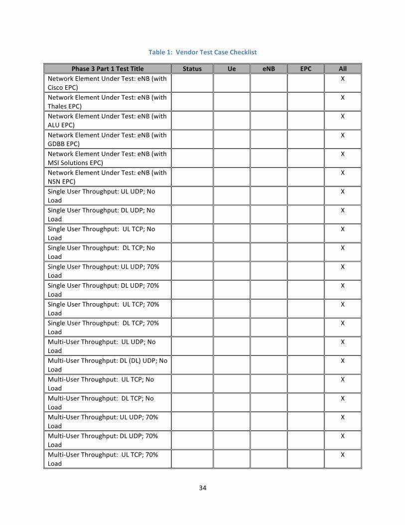
8 Vendor Test Case Checklist The purpose of the following test case checklist is to identify the Phase 3 test cases that are applicable to each vendor type. Some test cases are end-‐to-‐end by nature and will require the participation of a Ue, eNB, and EPC vendor in order to ensure that a given Phase 3 test can be successfully executed. The “All” category is defined as participation by Ue, eNB, and EPC vendors.
Every vendor who participates in the PSCR demonstration network will negotiate with PSCR to determine which tests will be required for successful execution of Phase 3.
34
Table 1: Vendor Test Case Checklist
Phase 3 Part 1 Test Title Status Ue eNB EPC All Network Element Under Test: eNB (with Cisco EPC)
X
Network Element Under Test: eNB (with Thales EPC)
X
Network Element Under Test: eNB (with ALU EPC)
X
Network Element Under Test: eNB (with GDBB EPC)
X
Network Element Under Test: eNB (with MSI Solutions EPC)
X
Network Element Under Test: eNB (with NSN EPC)
X
Single User Throughput: UL UDP; No Load
X
Single User Throughput: DL UDP; No Load
X
Single User Throughput: UL TCP; No Load
X
Single User Throughput: DL TCP; No Load
X
Single User Throughput: UL UDP; 70% Load
X
Single User Throughput: DL UDP; 70% Load
X
Single User Throughput: UL TCP; 70% Load
X
Single User Throughput: DL TCP; 70% Load
X
Multi-‐User Throughput: UL UDP; No Load
X
Multi-‐User Throughput: DL (DL) UDP; No Load
X
Multi-‐User Throughput: UL TCP; No Load
X
Multi-‐User Throughput: DL TCP; No Load
X
Multi-‐User Throughput: UL UDP; 70% Load
X
Multi-‐User Throughput: DL UDP; 70% Load
X
Multi-‐User Throughput: UL TCP; 70% Load
X

35
Multi-‐User Throughput: DL TCP; 70% Load
X
Network Latency: Single User; No Load X Network Latency: Single User; 70% Load X
9 Acronyms See 3GPP TR 21.905 V8.8.0 (2009-03) Section 4
10 Optional Information and Tests The information contained in this section is for comment, informational and contains optional tests.
10.1 Extra IOT Information5 Additional information beyond pass/fail maybe captured during the testing. This includes the following:
10.1.1 Verify Message Flow • Verify that the monitored message sequence is correct.
• Verify that the Attach Request message (step 2) contains the following mandatory information elements (IE): EPS attach type, NAS key set identifier, Old GUTI or IMSI, UE network capability, ESM message container. The other optional IEs: Old P-TMSI signature, Additional GUTI, DRX parameter, MS network capability and TMSI status may be included too.
• Verify that the Attach Accept message (step 16) contains the following mandatory information elements (IE): EPS attach result, T3412 value, TAI list, ESM message container. The other optional IEs may be included too.
• Verify that the Attach Complete message (step 21) contains the ESM message container IE.
• Verify that the INITIAL CONTEXT SETUP REQUEST message (step 16) contains the E-RAB to be Setup List IE, the ATTACH ACCEPT message on NAS level and the required optional IEs to establish a UE context in the eNB.
• Verify that the INITIAL CONTEXT SETUP RESPONSE message (step 19) contains the E-RAB Setup list of successfully established E-RABs.
• Verify that ATTACH REQUEST, ATTACH ACCEPT and ATTACH COMPLETE messages are transported successfully on the S1-MME interface.
• Verify that the related EPS Bearers have been established, and that the UE has been issued with an IP Address.
5 Appendix excerpt from MSF contribution: msf2009.178.02
36
10.1.2 Tracking Area Updates • Verify that the monitored message sequence is correct.
• Verify that the TAU Request message (from eNB to MME) contains the following mandatory information elements (IE): EPS Update Type, old GUTI, NAS key set identifier ASME. The other optional IEs may be included too.
• Verify that the TAU Accept message (from MME to eNB) contains the following mandatory information elements (IE): EPS Update result. The other optional IEs may be included too.
• Verify that the eNB send the TAU Complete message to MME if the GUTI is reallocated.
• Verify that TAU Request, TAU Accept and TAU Complete messages are transported successfully on the S1-MME interface.
• Verify that the UE is in EMM-REGISTERED and ECM- CONNECTED in MME after TAU complete.
• Verify the new TAI list
10.1.3 Detach Information • Verify that the Detach Request message (from eNB to MME) contains the following
mandatory information elements (IE): Detach type, NAS key set identifier and GUTI/IMSI.
• Verify that the Default bearer is deleted.
• Verify that the UE is in EMM-DEREGISTERED and ECM-IDLE after the detach is completed.
• Verify that DETACH Request,UE Context Release Command and UE Context Release Complete messages are transported successfully on the S1-MME interface.
37
10.2 Call Flow Diagram
10.2.1 UE Attach
1. Attach Request
MME S-GW PCRF HSS P-GW
2. Attach Request
eNodeB UE
3. Identity Request 4. Identity Response 5a. Authentication / Security
16. Initial Context Setup Request / Attach Accept
First Uplink Data
18. RRC Connection Reconfiguration Complete 17. RRC Connection Reconfiguration
19. Initial Context Setup Response
25. Modify Bearer Response
22. Modify Bearer Request
First Downlink Data 26. Notify Request 27. Notify Response
15. Create Session Response
10. Create Session Request
8. Update Location Request 9. Update Location Ack
11. Create Session Request
13. Create Session Response First Downlink Data
5b. Identity Request/Response
12. PCEF Initiated IP-CAN Session Establishment/Modification
6. Ciphered Options Request
7. Ciphered Options Response
23. Modify Bearer Request 24. Modify Bearer Response
20. Direct Transfer 21. Attach Complete

38
10.2.2 TAU UE Call Flow
10.2.3 UE Detach Call Flow
UE eNodeB MME
TAU Request
TAU Request
Authentication / Security
TAU Accept
TAU Accept
TAU Complete
HSS
TAU Complete
Authentication Information Request
Authentication Information Answer
UE eNodeB MME S-GW P-GW PCRF
Detach Request
Detach Accept
Delete Session Request
Delete Session Response
PCEF Initiated IP-CAN Session Termination
UE Context Release Command
UE Context Release Complete
Delete Session Request
Delete Session Response
HSS
Notify Request
Notify Answer