lte femtocell channel assignment using frequency time...
TRANSCRIPT
LTE FEMTOCELL CHANNEL ASSIGNMENT USING FREQUENCY TIME HOPPING
Louai Alkhateb Faculty of Engineering,
Multimedia University (MMU) Cyberjaya, Malaysia
Mohamad Yusoff Alias Faculty of Engineering,
Multimedia University (MMU) Cyberjaya, Malaysia [email protected]
Abstract—Femtocell deployment concept over a microcell has attracted tremendous attention in both industrial and academic environments. Femtocells face several challenges, one of these challenges is the interference mitigation between neighbouring femtocells themselves and between a femtocell and a macrocell. This is because both the femtocell and the macrocell share the same licensed frequency spectrum. Additionally, based on users' service requirements, the conventional radio source management techniques for hierarchical cellular systems does not suit that of femtocell networks due to the position of femtocells being random. This paper proposes a new co-channel interference (CCI) avoidance scheme using frequency time hopping technique for the downlink of Orthogonal Frequency-Division Multiple Access (OFDMA) based systems (e.g. Long Term Evolution (LTE) system). The proposed scheme eliminates the interference between femtocells. In addition, it maximizes the number of femtocells with limited number of subcarrier.
Index Terms—Femtocell, LTE, Interference management, OFDMA, Frequency time hopping.
I. INTRODUCTION Living in this day and age, the demand for an easily
accessible and very fast connection is increasing tremendously. People want to be able to have access to a reliable connection wherever they are, even while on the move, and they all need this connection to be as fast as possible. Thus with this growing need for fast and easily accessible connection, femtocells [1] provide for both requirements. With LTE femtocells, it provides both easily accessible and fast connection.
Femtocell is a small base station operating at licensed band [2] usually deploying indoor building such as houses or offices and malls. The operator has “no control” over the deployment location. Femtocells suffer from several challenges such as handover and interference. The interference can be divided into inter-tier and intra-tier interferences. The inter-tier interference, i.e. within one tier, is caused from cells that use the same frequency bands. Whereas, the intra-tier is the interference between different tiers and it is caused from different cells using different frequency bands.
In the recent years, there has been a booming expansion of cities in all aspects, leading to an undeniable demand for cellular wireless network and data coverage in all places. The demands above can be met in many ways; one of the proposed solutions
is via the dynamic spectrum allocation in femtocell [3]. It has been done based on the number of femtocell users. This solution can be divided into dynamic spectrum allocation between macrocell and femtocell, or inside the femtocell region. However, the limitation is the reduced spectral efficiency and since it had limited spectrum resource, the users may not reach high throughput.
Another solution scenario is using control information to avoid co-channel interference in two-tier LTE femtocell [4]. In this method Evolved Node Base Station (eNBs) is considered in suburban area where its coverage is a hexagon. Home eNB (HeNBs) are randomly deployed within the range of eNBs. Unfortunately, this system is limited to a house size of 12×12m. In addition, the HeNB cannot overlap in the same area, instead there should be a minimum distance separation of around 20 to 35cm between HeNB and eNB and from User Equipment (UE) to HeNB, respectively.
In this paper, frequency and time hopping technique is used to enlarge the number of femtocells using fixed number of channels. The remaining part of this paper is organized as follows. Interference management scheme is explained in Section III. Section IV describes the proposed solution to the interference and the mathematical equations used, while Section V is the simulation results. Finally, we conclude our paper in Section VI.
II. SYSTEM MODEL A femtocell functions like a mini-cellular base station.
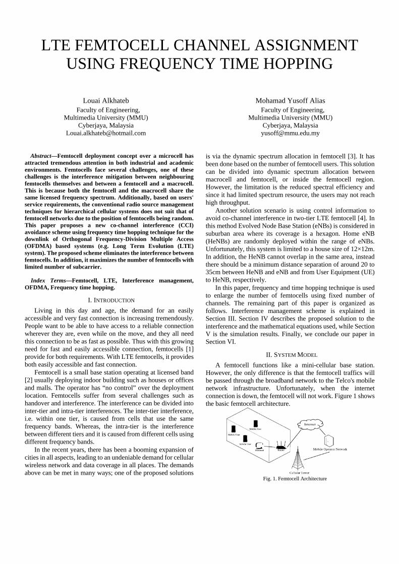
However, the only difference is that the femtocell traffics will be passed through the broadband network to the Telco's mobile network infrastructure. Unfortunately, when the internet connection is down, the femtocell will not work. Figure 1 shows the basic femtocell architecture.
Fig. 1. Femtocell Architecture
III. INTERFERENCE MANAGEMENT SCHEME
A. Orthogonal Frequency-Division Multiple Access (OFDMA) In OFDMA the available bandwidth is organized in resource
blocks of 180 KHz each, which is 12 subcarriers. One UE can be assigned either one resource block an example for this would be UE2 or multiple resources UE1 have been assigned free resource blocks to transmit on. The subcarrier spacing is 15 KHz and that can be seen by each 1ms. These assignments can change so the time domain in LTE is organized in sub-frames of each 1 ms. One sub-frame corresponds to a transmission time interval. Thus, for every 1 ms, the base station can change the scheduling decision. The distribution of the resource blocks among the users can change or be maintained such as UE2.
There is also the notion of a slot which is in the order of 5ms corresponding to 7 OFDMA symbols. These slots are introduced because the downlink reference symbols (pilot symbols) are repeated every slot. However, for the resources assignment, the transmission time interval of 1ms or sub-frame is the important part because it defines the scheduling interval. Thus, noting that each UE can transmit with another modulation scheme depending on the radio link quality for each UE, 64-Quadrature Amplitude Modulation can be assigned (64-QAM) [5].
B. Frequency-hopping Spread Spectrum Frequency-hopping spread spectrum (FHSS) is a technique
of transmitting radio signal by rapidly switching a carrier among other frequency channels. A pseudorandom sequence is applied which is already known to the sender and receiver. FHSS used as a multiple access method in frequency-hopping code division multiple access scheme spread spectrum. During transmission frequency hopping technique changes the frequency (uplink and downlink) at regular intervals. The frequency changes every Time Division Multiple Access (TDMA) frame (4.615ms) for the radio frequency channel that is used for signaling channel timeslot Standalone Dedicated Control Channels (SDCCH)) or traffic channel (TCH) timeslots. Thus, on a per burst basis, the frequency is changed, meaning, that all the bits in a burst are transmitted at the same frequency.
A spread-spectrum transmission offers three main advantages over the fixed-frequency transmission. Firstly, it is highly resistant to narrowband interference. Secondly, the process of re-collecting a spread signal spreads out the interfering signal, causing it to recede into the background. Thirdly, spread-spectrum signals are difficult to intercept, it may simply appear as an increase in the background noise to a narrowband receiver so an eavesdropper may have difficulty intercepting a transmission in real time if the pseudorandom sequence is not known. Spread-spectrum transmission can share a frequency band with many types of conventional transmissions. This sharing results in minimal interference as well as minimal noise to the narrow frequency communications, and vice versa. Thus, due to this property, bandwidth can be used more efficiently [6-7].
IV. PROPOSED SOLUTION In this method, the spectrum bandwidth is going to be
divided into several channels depending on each scenario. The number of channels will be changed but the technique will remain the same.
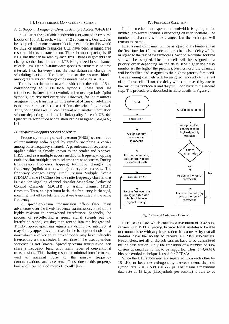
First, a random channel will be assigned to the femtocells in the first time slot. If there are no more channels, a delay will be assigned to the rest of the femtocells. Second, a counter for time slot will be assigned. The femtocells will be assigned in a priority order depending on the delay (the higher the delay number is, the higher the priority). Furthermore, the channels will be shuffled and assigned to the highest priority femtocell. The remaining channels will be assigned randomly to the rest of the femtocells. If not, the delay will be increased by one to the rest of the femtocells and they will loop back to the second step. The procedure is described in more details in Figure 2.
Fig. 2. Channel Assignment Flowchart
LTE uses OFDM which contains a maximum of 2048 sub-carriers with 15 kHz spacing. In order for all mobiles to be able to communicate with any base station, it is a necessity that all mobiles have the ability to receive all 2048 sub-carriers. Nonetheless, not all of the sub-carriers have to be transmitted by the base station. Only the transition of a number of sub-carriers as small as 72 has to be supported. Thus, 64-QAM 6 bits per symbol technique is used for OFDMA.
Since the LTE subcarriers are separated from each other by 15 kHz, to keep the orthogonality between them, then the symbol rate: T = 1/15 kHz = 66.7 µs. That means a maximum data rate of 15 ksps (kilosymbols per second) is able to be

carried by each subcarrier. This gives a 20 MHz bandwidth system a raw symbol rate of 18 Mbps. In turn, this is able to provide a raw data rate of 108 Mbps as each symbol using 64-QAM is able to represent six bits. Another reason for choosing a higher order formats is the possibility to transmit more bits per symbol.
Then next mathematical equations will show the proposed
solution to solve the issue.
The traffic channel can be calculated by:
ChannelsNumber of Bandwidthr channelTraffic pe
×××
=20
618 (1)
Where the total available bandwidth is multiplied by 18 which represent a row symbol rate as explained in the previous section, in addition the 64-QAM have 6 bit per symbol technique used for OFDMA. This will then be divided by the total number of channels that can be derived from the 20MHZ. The traffic per cell on the other hand can be calculated by:
Kbpsr UserTraffic peler per CelAverage Usr cellTraffic pe
6101)(
××
=(2)
On the other hand, the total traffic requested can be calculated using the traffic per cell calculated in Equation (2) and multiplied with the number of cells, window size and simulation cycle as given in the following equation:
CycleSimulationeWindow SizCellsNumber ofr CellTraffic petedfic requesTotal traf
×××=
The following two equations are giving the maximum delivered traffic and the drop traffic, respectively.
20618 Cycle SimulationeWindow SizBandwidth
afficlivered trMaximum de××××
=
)(20618
Kbpsr UserTraffic peerAverage UsBandwidth
icDrop traff
××××
= (5)
Later, we will be employing two cases to obtain our results.
Case 1: Traffic per Channel > Traffic per Cell
ChannelsNumber of Cycle SimulationeWindow Sizc per Cell Traffi
afficlivered trMaximum de
×××
= (6)
Case 2: Traffic per Channel < Traffic per Cell
20618 Cycle SimulationeWindow SizBandwidth
afficlivered trMaximum de××××
=
raffic at total t thent to findcell we waNumber of Cycle
SimulationeWindow Siz per Cell Traffictedfic requesTotal traf
×××
=
(8)
The QoS can then be obtained from:
tedfic RequesTotal TrafTrafficDelivered QoS = (9)
The reason behind dividing by 20 is referred to the maximum bandwidth that can be handled by the system.
V. RESULTS AND ANALYSIS The next figures (3 – 7) will show the optimum case scenario
for twice the number of femtocells for fixed number of channels:
Fig. 3. Channel Assignment to each cell
Fig. 4. Traffic-vs-Channel when number of femtocells is twice the number of channels
(4)
(7)
(3)

Fig. 5. QoS_Channel when number of femtocells is twice the number of channels
Fig. 6. Traffic-vs-Cells when number of femtocells is twice the number of channels
Fig. 7. QoS_Cells when number of femtocells is twice the number of channels
The next figures (8 – 12) will show the optimum case scenario for three times the number of femtocells for fixed number of channels:
Fig. 8. Channel Assignment to each cell
Fig. 9. Traffic-vs-Channel when number of femtocells is three times the number of channels
Fig. 10. QoS_Channel when number of femtocells is three times the number of channels

Fig. 11. QoS_Channel when number of femtocells is three times the number of channels
Fig. 12. QoS_Channel when number of femtocells is three times the number of channels
As it can be seen from the results the bandwidth will affect the maximum delivered traffic and the dropped traffic under number of channels results, while it will not affect the total traffic. On the other hand, in the number of cells results, the bandwidth will have effect only on Case 2 for maximum delivered traffic but it will have no effect on Case 1 or on the total traffic.
Going to the number of channels in number of channels results, there is no effect on the total traffic, maximum delivered traffic and dropped traffic. However, in the number of cells results, the effect is only on Case 1 for maximum delivered traffic. There is no effect on Case 2 or on total traffic.
For the average user per cell and traffic per user parameters under number of channels results, it will affect the total traffic and the drop traffic while it will not change the maximum delivered traffic number. For number of cells results, it can be seen from Case 1 that the total traffic for maximum delivered traffic will be affected while it remained the same for Case 2.
Moving into number of cells parameters, it can be seen that the total traffic, under number of channels results, is the only parameter affected while the other results are not affected. The number of cells results will also not affect any parameter at all.
The window size parameter will have an effect on both total traffic and maximum delivered traffic for number of channels
results while it will not affect the dropped traffic. On the other hand under the number of cells results, the window size will affect all the results (total traffic and maximum delivered traffic Case 1 and 2).
Finally for the simulation cycle under number of channels results the total traffic and maximum delivered traffic will both be affected but not the dropped traffic. Going to number of cells results, it can be seen that the results show the total traffic and maximum delivered traffic (Case 1 and 2).
TABLE I. ANALYSIS SUMMARY
Bandwidth (MHz)
Number of Channels
results
Total Traffic Not affected Maximum
Delivered Traffic Affected
Drop Traffic Affected Number of
Cells results
Total Traffic Not affected Maximum
Delivered Traffic Case 1 Not affected Case 2 Affected
Number of Channels
Number of Channels
results
Total Traffic Not affected Maximum
Delivered Traffic Not affected
Drop Traffic Not affected Number of
Cells results
Total Traffic Not affected Maximum
Delivered Traffic Case 1 Affected Case 2 Not affected
Average Users per Cell
Number of Channels
results
Total Traffic Affected Maximum
Delivered Traffic Not affected
Drop Traffic Affected Number of
Cells results
Total Traffic Affected Maximum
Delivered Traffic Case 1 Affected Case 2 Not affected
Traffic per User (Kbps)
Number of Channels
results
Total Traffic Affected Maximum
Delivered Traffic Not affected
Drop Traffic Affected Number of
Cells results
Total Traffic Affected Maximum
Delivered Traffic Case 1 Affected Case 2 Not affected
Number of Cells
Number of Channels
results
Total Traffic Affected Maximum
Delivered Traffic Not affected
Drop Traffic Not affected Number of
Cells results
Total Traffic Not affected Maximum
Delivered Traffic Case 1 Not affected Case 2 Not affected
Window Size (ms)
Number of Channels
results
Total Traffic Affected Maximum
Delivered Traffic Affected
Drop Traffic Not affected

Number of Cells
results
Total Traffic Affected Maximum
Delivered Traffic Case 1 Affected Case 2 Affected
Simulation Cycle
Number of Channels
results
Total Traffic Affected Maximum
Delivered Traffic Affected
Drop Traffic Not affected Number of
Cells results
Total Traffic Affected Maximum
Delivered Traffic Case 1 Affected Case 2 Affected
VI. CONCLUSION As stated earlier the aim of the project is to come up with a
new pattern using dynamic channel assignment to reduce the interference between femtocells and macrocells by implementing an interference avoidance scheme. Furthermore, another aim is to maximize the number of femtocells with limited number of subcarrier by using frequency time hopping technique. Thus, at the end of this research, the objectives have been achieved by assigning traffic per user to each femtocell.
This is achieved by using frequency-time hopping technique by analyzing the total traffic in femtocell by means of accounting for number of channels or number of cells in addition to the user traffic requested is founded and the dropped traffic. Also the quality of service for the femtocell is founded too.
Lastly, using this method will allow the carrier provide to at least double the number of femtocells for a fixed limited number of channels and that leads to more femtocells and more users to take off traffic from the main macrocells.
REFERENCES [1] V.Chandrasekhar, J. Andrews and A. Gatherer, “Femtocell
Networks: A survey”, in proc. IEEE comm. Mag., Vol.46, No.9, pp.59-67, Sep. 2008.
[2] G. de la Roche, A. Valcarce, D. Lopez-Perez, and J. Zhang, “Access control mechanisms for femtocells,” IEEE Commun. Mag., vol. 48, no. 1, pp. 33–39, Jan. 2010
[3] R. V. Sathya and B. R. Tamma, "Dynamic spectrum allocation in Femto based LTE network," in Proc. 5th International Communication Systems and Networks (COMSNETS), Jan. 2013.
[4] S. Chhorn, S.-o. Seo, M. H. Mohsini, and C.-h. Cho, “Co-channel interference avoidance in two-tier LTE femtocell systems using control information,” in Asia-Pacific Conference on Communications, Bali - Indonesia, 29-31 Aug. 2013, pp. 202 – 207.
[5] H. Ishikawa, M. Furudate, T. Ohseki, and T. Suzuki, “Performance analysis of adaptive downlink modulation using OFDM and MC-CDMA for future mobile communications system,” in Proc. IEEE ISSSTA, Aug./Sep. 2004, pp. 194–198.
[6] S. Zoican, “Frequency hopping spread spectrum technique for wireless communication systems,” IEEE 5th Int. Symp. on Spread Spectrum Techniques and Applications, vol. 1, pp. 338-341, Sept. 1998.
[7] H. Zhao, Z. Yang, and Y. Zhao, "Frequency-Hopping Narrowband Interference Suppression in Spread-Spectrum Systems," presented at the Vehicular Technology Conference (VTC Spring), 2013 IEEE 77th, Dresden, 2-5 June 2013.