lte link design in southern railway 31.07.2020)
TRANSCRIPT
“LTE Link Design in Chennai- Gummidipundi (MAS-GPD) section of Southern Railway”SAG0112 (06.07.2020 –31.07.2020)
Sandeep Kumar
Chief Communication Engineer Southern Railway
Photo: Ponneri (Commercial Site)
“LTE Link Design MAS-GPD section of Southern Railway”
• LTE Network Introduction: I834 RKM sanctioned
• LTE Design: EPC(Evolved Packet Core)
• LTE Design: EUTRAN(Evolved UMTS Terrestrial Radio Access Network)
• QoS
• Path Loss
• Conclusion
Photo: Ponneri (Commercial Site)
UE
E-
UTRAN
EPC
Uu S1
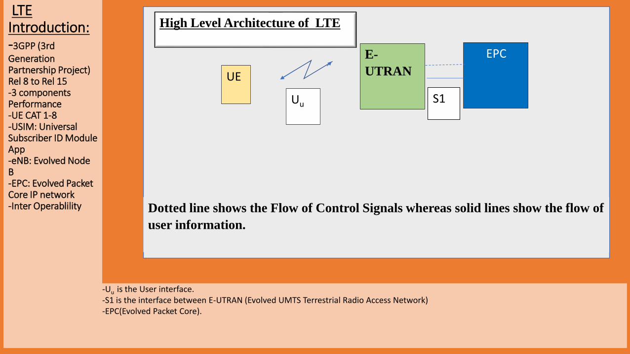
Dotted line shows the Flow of Control Signals whereas solid lines show the flow of
user information.
High Level Architecture of LTELTE Introduction:-3GPP (3rd Generation Partnership Project) Rel 8 to Rel 15-3 componentsPerformance-UE CAT 1-8-USIM: Universal Subscriber ID Module App-eNB: Evolved Node B-EPC: Evolved Packet Core IP network-Inter Operablility
-Uu is the User interface. -S1 is the interface between E-UTRAN (Evolved UMTS Terrestrial Radio Access Network)-EPC(Evolved Packet Core).
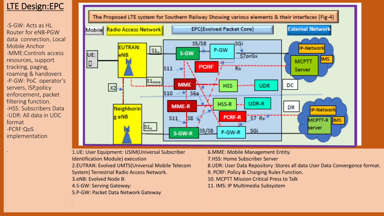
LTE Design:EPC
-S-GW: Acts as HL Router for eNB-PGW data connection, Local Mobile Anchor-MME:Controls access resources, support tracking, paging, roaming & handovers-P-GW: PoC operator’s servers, ISP,policyenforcement, packet filtering function.-HSS: Subscribers Data-UDR: All data in UDC format-PCRF:QoSimplementation
. 1.UE: User Equipment: USIM(Universal Subscriber Identification Module) execution2.EUTRAN: Evolved UMTS(Universal Mobile Telecom System) Terrestrial Radio Access Network.3.eNB: Evolved Node B:4.S-GW: Serving Gateway:5.P-GW: Packet Data Network Gateway
6.MME: Mobile Management Entity.7.HSS: Home Subscriber Server 8.UDR: User Data Repository :Stores all data User Data Convergence format.9. PCRF: Policy & Charging Rules Function.10. MCPTT Mission Critical Press to Talk11. IMS: IP Multimedia Subsystem

MAS-GPD Section Details SN STATION NAME STN CODE RKM1 Puratchi Thalaivar Dr. M.G. Ramachandran Central MAS 0
2 Basin Bridge Jn BBQ 13 Korukkupet Jn KOK 34 Tondiarpet(H) TNP 45 VOC Nagar(H) VOC 66 Tiruvottiyur TVT 87 Wimco Nagar(H) WIMCO 108 Kathivakkam(H) KAVM 139 Ennore ENR 14
10 Attippattu Pudunagar (H) AIPP 1911 Attippattu AIP 2012 Nandiyambakkam(H) NPKM 2213 Minjur MJR 25
14 Anuppambattu APB 29
15 Ponneri PON 33
16 Kavaraippettai KVP 40
17 Gummidipundi GPD 46

EUTRAN Design-PLMN ID(Public Land Mobile Network Identity): Mobile Country Code (MCC)& Mobile Network Code (MNC). -E-UTRAN cell identity (ECI)=20 bit eNB ID&8 bit cell ID. ECI identifies a cell uniquely within a particular network as eNB ID is unique to a particular Operator.- E-UTRAN cell global identifier (ECGI) identifies a cell anywhere in the world. ECGI=ECI+PLMN-ID. -Cell is usually the same thing as a sector controlled by base station .-Overlapping: Diff colors-Min 2- Ant to reduce fading-X2-2mbps-eNB to EPC-1Gbps-Core 10 Gbps

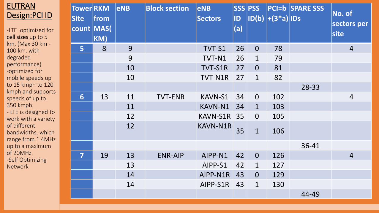
EUTRAN Design:PCI ID
-PCI:Physical cell identity:0 and 503- “PCI = 3*SSS ID + PSS ID” -SSS ID”(Secondary Sync Signal ID) is the cell ID of group:0 to 167 and is signalled using the SSS(Secondary Synch Signal). -“PSS ID”(Physical Synch Signal identity) cell ID within the group:0 to 2 and is signalledusing the PSS(Physical Synchronization Signal).PSS identifies each of the sector formed by the transmitted ant.
Tower
Site
count
RKM eNB Block section eNB
Sectors
SSS
ID
(a)
PSS
ID(b)
PCI=b+
(3*a)
SPARE SSS
IDs
No. of
sectors per
site 1 0 1 MAS-BBQ MAS-N1 0 0 0 2
2 MAS-N1R 1 0 3
2 3 MMC-N1 2 0 6 24 MMC-N1R 3 0 9
4 to 93 1 5 BBQ-N1 10 0 30 6
5 BBQ-S1 10 1 31
5 BBQ-S2 10 2 32
6 BBQ-N1R 11 0 33
6 BBQ-S1R 11 1 34
6 BBQ-S2R 11 2 35
12 to 174 4 7 KOK-TVT TNP-S1 18 0 54 4
7 TNP-N1 18 1 55
8 TNP-S1R 19 0 57
8 TNP-N1R 19 1 58
20 to 25
EUTRAN Design:PCI ID
-LTE optimized for cell sizes up to 5 km, (Max 30 km -100 km. with degraded performance) -optimized for mobile speeds up to 15 kmph to 120 kmph and supports speeds of up to 350 kmph. - LTE is designed to work with a variety of different bandwidths, which range from 1.4MHz up to a maximum of 20MHz.-Self Optimizing Network
Tower
Site
count
RKM
from
MAS(
KM)
eNB Block section eNB
Sectors
SSS
ID
(a)
PSS
ID(b)
PCI=b
+(3*a)
SPARE SSS
IDsNo. of
sectors per
site
5 8 9 TVT-S1 26 0 78 49 TVT-N1 26 1 79
10 TVT-S1R 27 0 8110 TVT-N1R 27 1 82
28-336 13 11 TVT-ENR KAVN-S1 34 0 102 4
11 KAVN-N1 34 1 10312 KAVN-S1R 35 0 10512 KAVN-N1R
35 1 106
36-417 19 13 ENR-AIP AIPP-N1 42 0 126 4
13 AIPP-S1 42 1 12714 AIPP-N1R 43 0 12914 AIPP-S1R 43 1 130
44-49
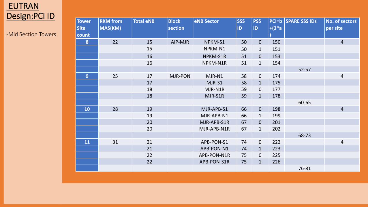
EUTRAN Design:PCI ID
-Mid Section Towers
Tower
Site
count
RKM from
MAS(KM)
Total eNB Block
section
eNB Sector SSS
ID
PSS
ID
PCI=b
+(3*a
)
SPARE SSS IDs No. of sectors
per site
8 22 15 AIP-MJR NPKM-S1 50 0 150 415 NPKM-N1 50 1 151
16 NPKM-S1R 51 0 15316 NPKM-N1R 51 1 154
52-579 25 17 MJR-PON MJR-N1 58 0 174 4
17 MJR-S1 58 1 17518 MJR-N1R 59 0 17718 MJR-S1R 59 1 178
60-6510 28 19 MJR-APB-S1 66 0 198 4
19 MJR-APB-N1 66 1 19920 MJR-APB-S1R 67 0 20120 MJR-APB-N1R 67 1 202
68-7311 31 21 APB-PON-S1 74 0 222 4
21 APB-PON-N1 74 1 22322 APB-PON-N1R 75 0 22522 APB-PON-S1R 75 1 226
76-81

EUTRAN Design: PCI ID
-15 Tower Site-PCI IDs utilized 0 to 322-Sectors:58 nos-eNB:30 nos
Tower
Site
count
RKM from
MAS(KM)
Total eNB Block
section
eNB Sector SSS
ID
PSS ID PCI=b+(3*a) SPARE SSS
IDs No. of
sectors per
site
12 33 23 PON-KVP PON-S1 82 0 246 423 PON-N1 82 1 247
24 PON-S1R 83 0 249
24 PON-N1R 83 1 250
84-8913 40 25 KVP-GPD KVP-S1
90 0 270 425 KVP-N1 90 1 271
26 KVP-S1R 91 0 273
26 KVP-N1R 91 1 27492-97
14 43 27 KVP-GPD-S1 98 0 294 427 KVP-GPD-N1 98 1 29528 KVP-GPD-S1R 99 0 297
28 KVP-GPD-N1R 99 1 298
100-10515 46 29 GPD GPD-S1 106 0 318 4
29 GPD-N1 106 1 319
30 GPD-S1R 107 0 32130 GPD-N1R 107 1 322
Total 58

A Typical eNB site(Commercial)
Ponneri Site

“A Typical RRH & Antenna ( Commercial)”
Ponneri Site

“A Typical Cabling
Arrangement ( Commercial)”
Arakkkonam site
Coaxial Cable for Microwave( NA for Rly)
Power Cable
OFC cable

LTE:eNB Components
-Antenna
-RRh
-CPRI
-BBU
-Router

LTE QoS:
-QCI 0.7,1.9,2.1,2.2,2.4, to 4,2.5 is GBR(Guarnteed Bit Rate)
-QCI 0.5,5.5,6.5,6.8,1 &6-9 is Non-GBR.0.5
-In R-12 & 14 it was further expanded.
QCI priority services (Suggested)
2 ETCS L-2,TCAS,Emergency services
4 Real time Important content like accident site
3 Real time content
5 Buffered video like Ads in Platform
1 Train Control signalling ,IMS signalling
6 Train Monitoring services (high priority users)
7 Voice, real time video, real time games
8 Web, email, FTP (mid priority users)
9 Web, email, FTP (low priority users)
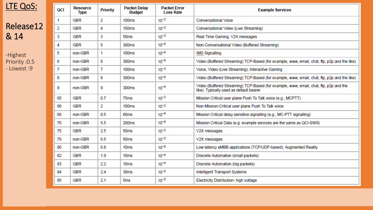
LTE QoS:
Release12& 14
-Highest Priority :0.5- Lowest :9
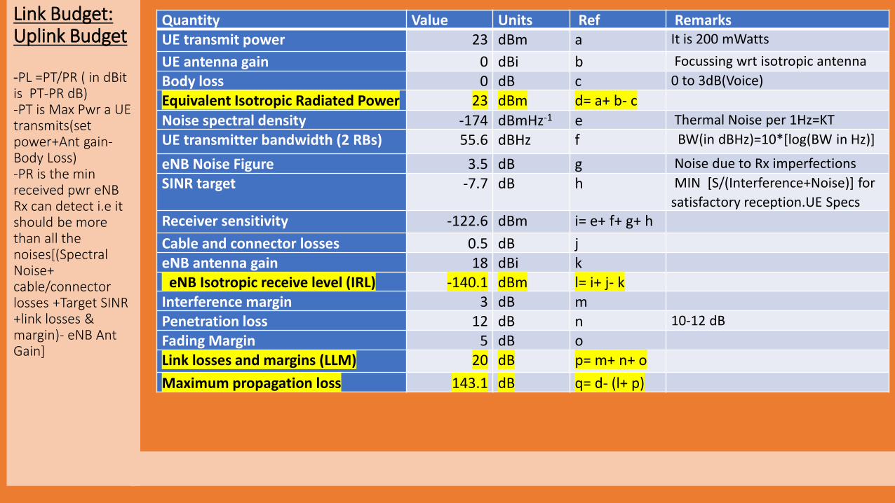
Link Budget:Uplink Budget
-PL =PT/PR ( in dBitis PT-PR dB)-PT is Max Pwr a UE transmits(set power+Ant gain-Body Loss)-PR is the min received pwr eNB Rx can detect i.e it should be more than all the noises[(Spectral Noise+ cable/connector losses +Target SINR +link losses & margin)- eNB Ant Gain]
Quantity Value Units Ref RemarksUE transmit power 23 dBm a It is 200 mWatts
UE antenna gain 0 dBi b Focussing wrt isotropic antenna
Body loss 0 dB c 0 to 3dB(Voice)
Equivalent Isotropic Radiated Power 23 dBm d= a+ b- c
Noise spectral density -174 dBmHz-1 e Thermal Noise per 1Hz=KT
UE transmitter bandwidth (2 RBs) 55.6 dBHz f BW(in dBHz)=10*[log(BW in Hz)]
eNB Noise Figure 3.5 dB g Noise due to Rx imperfections
SINR target -7.7 dB h MIN [S/(Interference+Noise)] for
satisfactory reception.UE Specs
Receiver sensitivity -122.6 dBm i= e+ f+ g+ h
Cable and connector losses 0.5 dB j eNB antenna gain 18 dBi k
eNB Isotropic receive level (IRL) -140.1 dBm l= i+ j- kInterference margin 3 dB m Penetration loss 12 dB n 10-12 dB
Fading Margin 5 dB o Link losses and margins (LLM) 20 dB p= m+ n+ o
Maximum propagation loss 143.1 dB q= d- (l+ p)

Link Budget:Down link Budget:
-PT is Max eNB transmits Pwr( eNB Tx Pwr+Ant G-Cable/connect L)
-PR is the min received pwr UE can detect i.e it should be more than all the noises[(Spectral Noise+ cable/connector losses +Target SINR +link losses & margin)- UE Ant Gain]
Quantity Value Units Ref Remarks
eNB transmit power 43 dBm a 40 watts
Cable and connector losses 0.5 dB b
eNB antenna gain 18 dBi c Focussing wrt isotropic Ant
Equivalent isotropic radiated power 60.5 dBm d= a-b+c
Noise spectral density -174 dBmHz-1 e Thermal Noise per 1Hz=KT
eNB transmitter bandwidth 66.53 dBHz f BW(in dBHz)=10*[log(BW in Hz)]
UE Noise Figure 7 dB g
SINR target -4.2 dB h
Receiver sensitivity -96.27 dBm i= e+ f+ g+ h
Body loss 0 dB c
UE antenna gain 0 dBi k
Isotropic Receive Level (IRL) -96.27 dBm l= i+ j- k
Interference margin 2.1 dB m
Penetration loss 12 dB n 10-12 dB
Fading Margin 5 dB o
Link losses and margins (LLM) 19.1 dB p= m+ n+ o
Maximum propagation loss 137.67 dB q= d-( l+p)
Through path loss we can calculate max cell distance
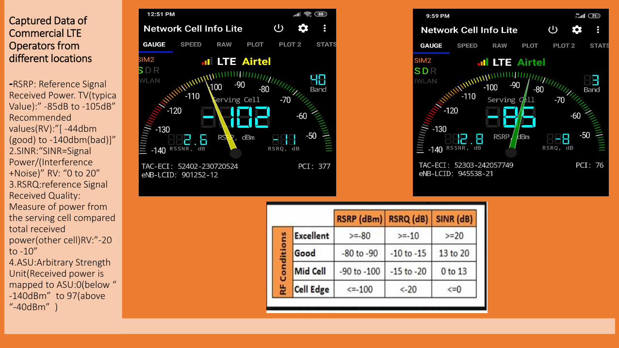
Captured Data of Commercial LTE Operators from different locations
-RSRP: Reference Signal Received Power. TV(typica Value):” -85dB to -105dB” Recommended values(RV):”[ -44dbm (good) to -140dbm(bad)]”2.SINR:“SINR=Signal Power/(Interference +Noise)” RV: “0 to 20”3.RSRQ:reference Signal Received Quality: Measure of power from the serving cell compared total received power(other cell)RV:”-20 to -10”4.ASU:Arbitrary Strength Unit(Received power is mapped to ASU:0(below “ -140dBm” to 97(above “-40dBm” )

“LTE works on both FDD & TDD mode(once at a time).
FDD frequency band range from 1 to 31 & 65 to 88( used in India areVoda:Band 1:2100MHz,Band 3:800Mhz, Band 8:900Mhz,Airtel: Band 1, Band 3, Band 4-1800MHz & Band 8:,JIO: Band 3, Band 5:850 MHz & Band 8).TDD bands range from 33 to 53. In India, all operators use Band 40-2300MHz.MCC(Mobile country code for India is 404, 405 & 406).

MCPTT(Mission Critical Press To Talk):
-3GPP Proximity Services (ProSe) -MCD(Mission Critical Data) ,MCV( Mission Critical Video) ,Land Mobile Radio(LMR) services were introduced for MCPTT-OTT App-Dedicated sets

Conclusion:
-Safety of data is Imp(AAA)Diameter-Multiple antennae will reduce fading-Redundancy - Cell planning -Drive Test Imp-Uplink & Downlink power budget is to be ascertained by working out Path Loss & a rough cell size- Power requirement per eNB will be 3-5KVA-Repetition of PCI after 50- 60 Km-Microcell for crowded places like Major junction control office
SN EUTRAN: Item Description Qty-Unit Refernce
1 Baseband Unit(BBU) 30- set 1 per eNB
2 Remote Radio Unit (RRU) 30 -nos 1 per eNB3 Antennas 116- nos. 2- per sector.
4 CPRI(Central Public Radio Interface) 30 -set 1 per eNB
5 Site Router 30-no. 1- per eNB6 Batteries (600AH) 60-set 2 per eNB7 Charger(100 Amps) 60-nos 2 per eNB8 Monopole – 30 Mts/9-meter pole 15-nos 1 per eNB9 Cabinet 30-nos 1 per eNB10 Application Software for LTE-RAN 30 -LS 1 per eNB11 Micro Cell 1 LS MAS Platform12 Hardware for EPC Application software for
EPC(HSS,MME,S-GW,PDN,PCRF)
2- set 1 each for DC &1 for DR
each
13 Application Software for EPC Application
software for EPC(HSS,MME,S-GW,PDN,PCRF)
2- LS 1 each for DC &1 for DR
each
14 NMS software including client( One per
division)
1- set 1 per division

Question Time