lte planning tool atoll 1
DESCRIPTION
networkTRANSCRIPT
1 © Nokia Siemens Networks LTE Radio Planning Tool –ATOLL / Jose Maria Anarte / v1.0 / Document NumberFor public use – IPR applies
LTE Radio Planning Tool - ATOLLLTE Radio Planning Essentials course

2 © Nokia Siemens Networks LTE Radio Planning Tool - ATOLL / Jose Maria Anarte / v1.0 / Document NumberFor public use – IPR applies
Nokia Siemens Networks Academy
Legal notice
Intellectual Property RightsAll copyrights and intellectual property rights for Nokia Siemens Networks training documentation, product documentation and slide presentation material, all of which are forthwith known as Nokia Siemens Networks training material, are the exclusive property of Nokia Siemens Networks. Nokia Siemens Networks owns the rights to copying, modification, translation, adaptation or derivatives including any improvements or developments. Nokia Siemens Networks has the sole right to copy, distribute, amend, modify, develop, license, sublicense, sell, transfer and assign the Nokia Siemens Networks training material. Individuals can use the Nokia Siemens Networks training material for their own personal self-development only, those same individuals cannot subsequently pass on that same Intellectual Property to others without the prior written agreement of Nokia Siemens Networks. The Nokia Siemens Networks training material cannot be used outside of an agreed Nokia Siemens Networks training session for development of groups without the prior written agreement of Nokia Siemens Networks.

3 © Nokia Siemens Networks LTE Radio Planning Tool - ATOLL / Jose Maria Anarte / v1.0 / Document NumberFor public use – IPR applies
Module Objectives
After completing this module, the participant should be able to:
•Describe the basic settings and options in the ATOLL radio planning tool for LTE•Examine the Traffic Modelling ATOLL•Revise the Monte Carlo Simulations done with ATOLL•Explain the MIMO setting in ATOLL•Understand how to produce Traffic Maps with ATOLL
4 © Nokia Siemens Networks LTE Radio Planning Tool - ATOLL / Jose Maria Anarte / v1.0 / Document NumberFor public use – IPR applies
Module Contents
• ATOLL for LTE: Basic Concepts & Settings
• Traffic Modelling
• Monte Carlo Simulations
• MIMO in ATOLL
• Creating Traffic Maps in ATOLL

5 © Nokia Siemens Networks LTE Radio Planning Tool - ATOLL / Jose Maria Anarte / v1.0 / Document NumberFor public use – IPR applies
Module Contents
• ATOLL for LTE: Basic Concepts & Settings
• Traffic Modelling
• Monte Carlo Simulations
• MIMO in ATOLL
• Creating Traffic Maps in ATOLL
6 © Nokia Siemens Networks LTE Radio Planning Tool - ATOLL / Jose Maria Anarte / v1.0 / Document NumberFor public use – IPR applies
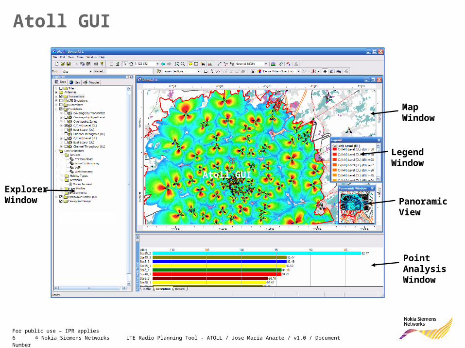
Explorer Window
Map Window
Point Analysis Window
Legend Window
Panoramic View
Atoll GUI
Atoll GUI

7 © Nokia Siemens Networks LTE Radio Planning Tool - ATOLL / Jose Maria Anarte / v1.0 / Document NumberFor public use – IPR applies
Network Design Workflow
8 © Nokia Siemens Networks LTE Radio Planning Tool - ATOLL / Jose Maria Anarte / v1.0 / Document NumberFor public use – IPR applies
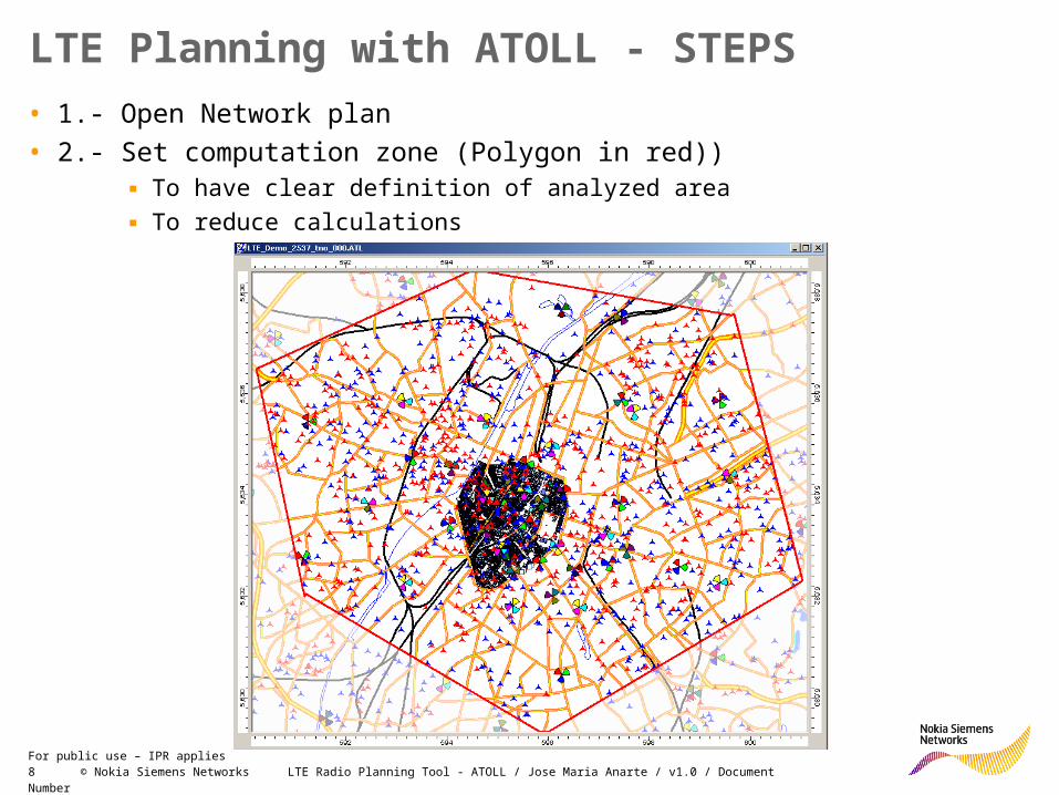
LTE Planning with ATOLL - STEPS
• 1.- Open Network plan
• 2.- Set computation zone (Polygon in red))▪ To have clear definition of analyzed area
▪ To reduce calculations

9 © Nokia Siemens Networks LTE Radio Planning Tool - ATOLL / Jose Maria Anarte / v1.0 / Document NumberFor public use – IPR applies
Network Design (1/2)
Networks consist of Base Stations ( eNodeB) comprising
• Sites = Locations– Geographical locations of base stations
– Can support one or more transmitters
– Sites database can be shared with Atoll Microwave
• Transmitters = Radio Aerials– Comprises radio transmission/reception parameters and antennas
– Can handle one or several antennas and MIMO systems
– Can be linked to a TMA, feeder cables, and other equipment
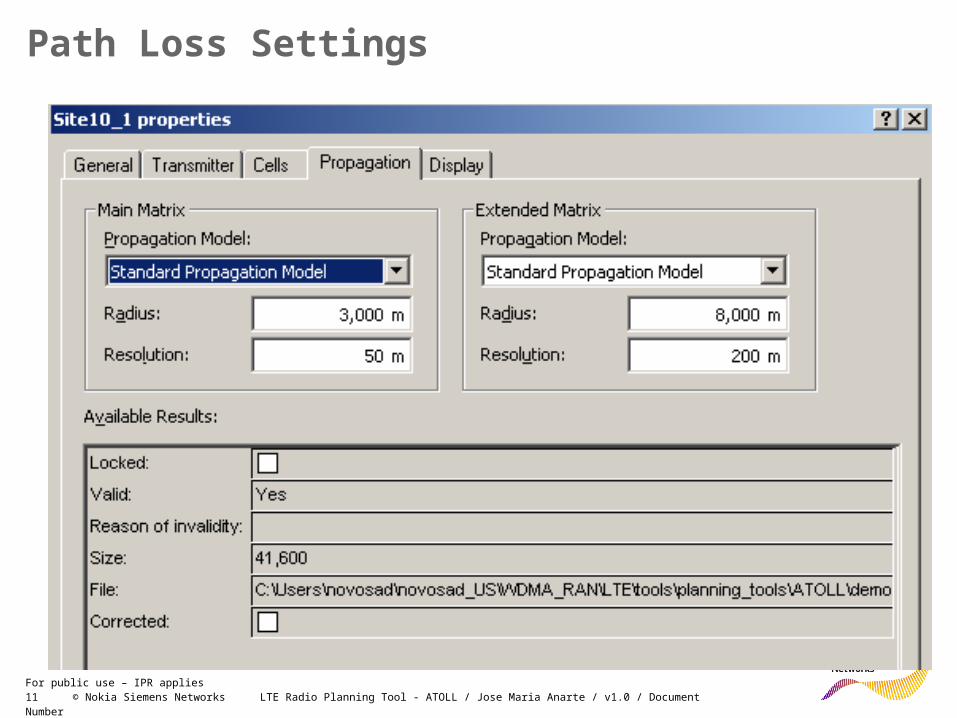
– Can have up to two path loss matrices: a high-resolution path loss matrix for precise results near the transmitter and a low-resolution path loss matrix for interference calculation far from the transmitter
– Supports cells (carriers) with parameters defined at cell level
• Other base station parameters– Cyclic prefix, PDCCH and PUCCH channel overheads, switching point
periodicity for TDD frames, uplink power control margin
Network Entities in ATOLL (1/2)

10 © Nokia Siemens Networks LTE Radio Planning Tool - ATOLL / Jose Maria Anarte / v1.0 / Document NumberFor public use – IPR applies
Networks consist of Base Stations (eNodeB) comprising
• Cells = Radio Channels– Hardware unit supporting an RF channel, i.e., 1 cell = 1 carrier
– Has a certain traffic capacity limited by the channel bandwidth
– Main properties of a Cell:▪ Channel (frequency band, channel number, and bandwidth)
▪ Transmission power
▪ Reception equipment
▪ Scheduler
▪ Maximum number of simultaneous active users
▪ AMS threshold (Adaptive MIMO Switching)
▪ Uplink and downlink traffic loads
▪ Uplink noise rise
▪ TDD frame configuration
▪ Antenna diversity support (Transmit Diversity, Spatial Multiplexing, AMS)
▪ Neighbours
Network Entities in ATOLL (2/2)
11 © Nokia Siemens Networks LTE Radio Planning Tool - ATOLL / Jose Maria Anarte / v1.0 / Document NumberFor public use – IPR applies
Path Loss Settings
12 © Nokia Siemens Networks LTE Radio Planning Tool - ATOLL / Jose Maria Anarte / v1.0 / Document NumberFor public use – IPR applies
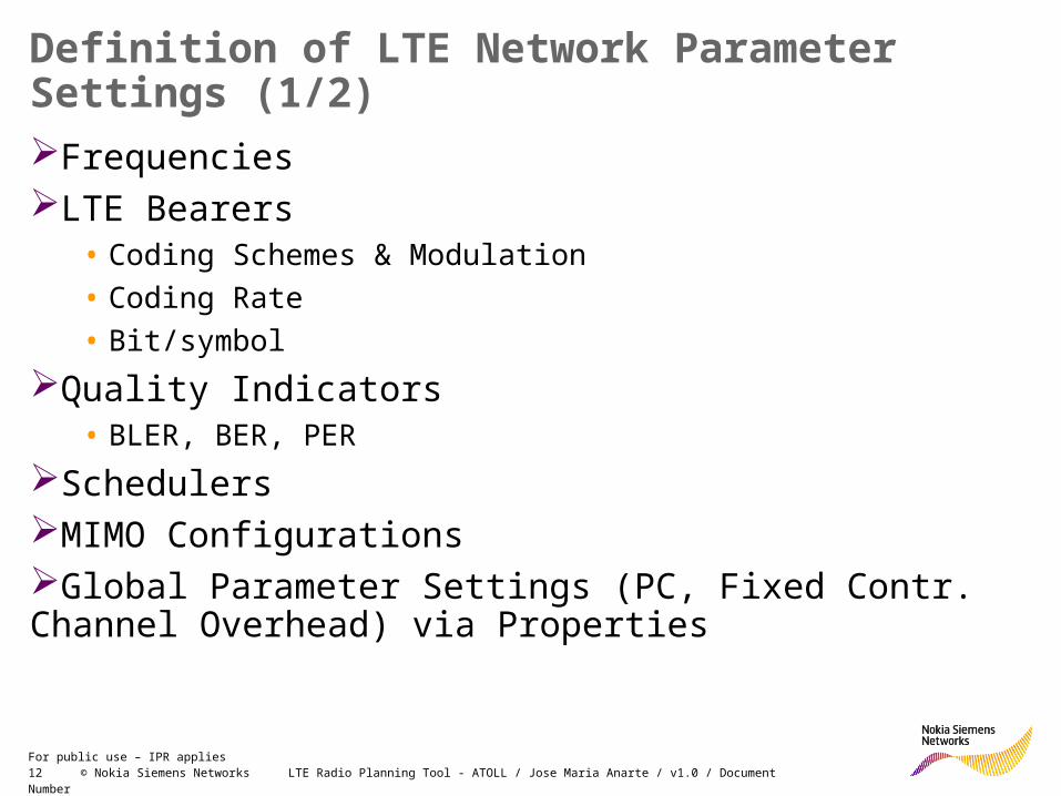
Definition of LTE Network Parameter Settings (1/2)
FrequenciesLTE Bearers
• Coding Schemes & Modulation
• Coding Rate
• Bit/symbol
Quality Indicators• BLER, BER, PER
SchedulersMIMO ConfigurationsGlobal Parameter Settings (PC, Fixed Contr. Channel Overhead) via Properties
13 © Nokia Siemens Networks LTE Radio Planning Tool - ATOLL / Jose Maria Anarte / v1.0 / Document NumberFor public use – IPR applies
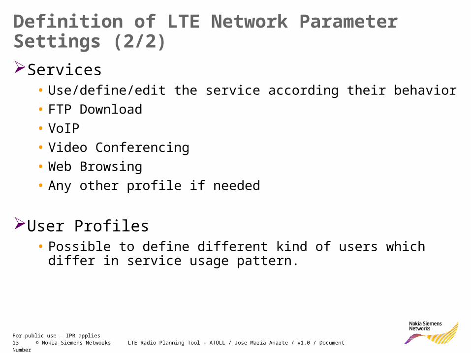
Definition of LTE Network Parameter Settings (2/2)
Services• Use/define/edit the service according their behavior
• FTP Download
• VoIP
• Video Conferencing
• Web Browsing
• Any other profile if needed
User Profiles• Possible to define different kind of users which differ in service usage
pattern.

14 © Nokia Siemens Networks LTE Radio Planning Tool - ATOLL / Jose Maria Anarte / v1.0 / Document NumberFor public use – IPR applies
• Atoll can model multi-band networks within the same document
• Pre-defined frequency bands
• Possibility to easily create / modify frequency bands
• Support for multiple channel bandwidths and different sampling frequencies
• TDD and FDD frequency bands supported
LTE Frequency Bands
15 © Nokia Siemens Networks LTE Radio Planning Tool - ATOLL / Jose Maria Anarte / v1.0 / Document NumberFor public use – IPR applies
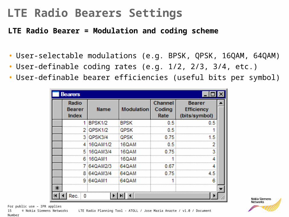
LTE Radio Bearers Settings
LTE Radio Bearer = Modulation and coding scheme
• User-selectable modulations (e.g. BPSK, QPSK, 16QAM, 64QAM)
• User-definable coding rates (e.g. 1/2, 2/3, 3/4, etc.)
• User-definable bearer efficiencies (useful bits per symbol)

16 © Nokia Siemens Networks LTE Radio Planning Tool - ATOLL / Jose Maria Anarte / v1.0 / Document NumberFor public use – IPR applies
LTE Bearers: NSN Setting (in line with dim tool)
User bits per modulation symbol as per dimensioning tool
Bearer efficiency divided by # bits per modulation
symbol (2 for QPSK, 4 for 16QAM and 6 for 64QAM
17 © Nokia Siemens Networks LTE Radio Planning Tool - ATOLL / Jose Maria Anarte / v1.0 / Document NumberFor public use – IPR applies
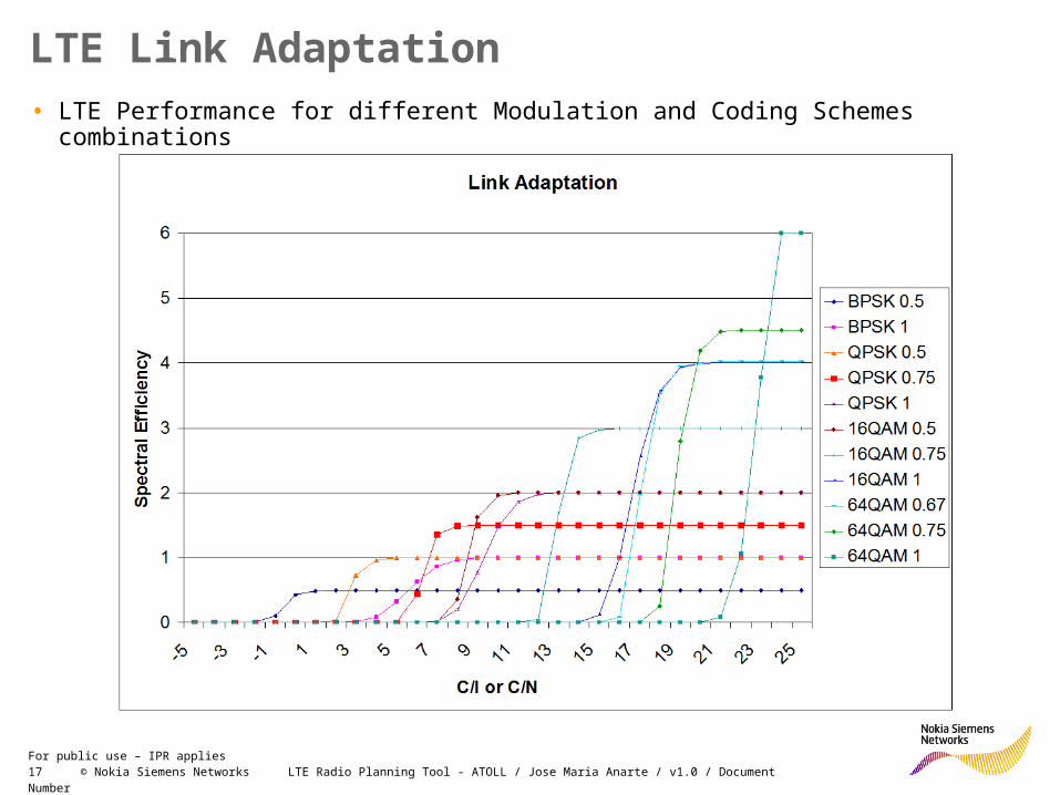
LTE Link Adaptation
• LTE Performance for different Modulation and Coding Schemes combinations

18 © Nokia Siemens Networks LTE Radio Planning Tool - ATOLL / Jose Maria Anarte / v1.0 / Document NumberFor public use – IPR applies
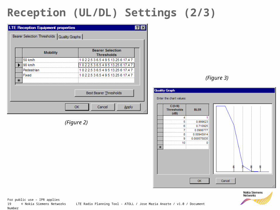
Reception (UL/DL) Settings (1/3)
Reception Equipment• Bearer selection thresholds for
automatic link adaptation based on CINR values (Figure 1)
• Channel quality indicator graphs based on CINR values (Figure 2 & 3 on next slide)
• Peak Channel Throughput (without errors) / Effective Channel Throughput (with errors). Both of them are used to model reception characteristics at the mobile (DL) and at the cell (UL).
(Figure 1)
19 © Nokia Siemens Networks LTE Radio Planning Tool - ATOLL / Jose Maria Anarte / v1.0 / Document NumberFor public use – IPR applies
Reception (UL/DL) Settings (2/3)
(Figure 2)
(Figure 3)
20 © Nokia Siemens Networks LTE Radio Planning Tool - ATOLL / Jose Maria Anarte / v1.0 / Document NumberFor public use – IPR applies
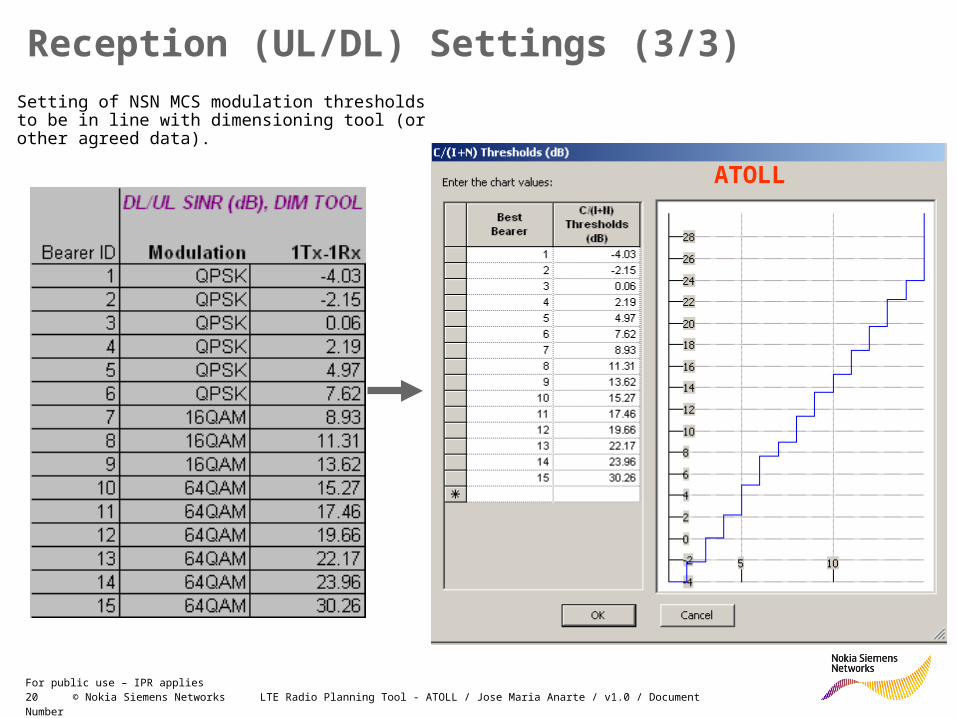
Reception (UL/DL) Settings (3/3)
ATOLL
Setting of NSN MCS modulation thresholds to be in line with dimensioning tool (or other agreed data).
21 © Nokia Siemens Networks LTE Radio Planning Tool - ATOLL / Jose Maria Anarte / v1.0 / Document NumberFor public use – IPR applies
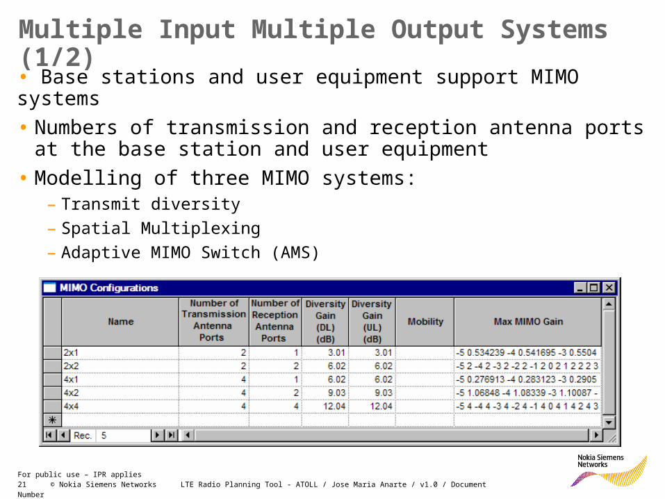
• Base stations and user equipment support MIMO systems
• Numbers of transmission and reception antenna ports at the base station and user equipment
• Modelling of three MIMO systems:– Transmit diversity
– Spatial Multiplexing
– Adaptive MIMO Switch (AMS)
Multiple Input Multiple Output Systems (1/2)

22 © Nokia Siemens Networks LTE Radio Planning Tool - ATOLL / Jose Maria Anarte / v1.0 / Document NumberFor public use – IPR applies
• Transmit Diversity improves the C/(I+N)
Usually used in coverage areas with bad radio conditions
• Spatial Multiplexing improves throughput
Usually used in coverage areas with good radio conditions
• AMS-capable equipment can switch from Spatial Multiplexing to Transmit Diversity as the radio conditions worsen
Multiple Input Multiple Output Systems (2/2)

23 © Nokia Siemens Networks LTE Radio Planning Tool - ATOLL / Jose Maria Anarte / v1.0 / Document NumberFor public use – IPR applies
Services
• Modelling of Voice and Data services
• Support for service prioritiesconsidered for scheduling and RRM
• Modelling of traffic demand parameters:– Minimum throughput demand = GBR
– Maximum throughput demand = MBR
– Activity factor for voice type services
• Modelling of application layer overheads
Mobility Types
• Modelling of mobile speed
• Used for bearer selection, and channel quality indicator graphs
Services Settings
24 © Nokia Siemens Networks LTE Radio Planning Tool - ATOLL / Jose Maria Anarte / v1.0 / Document NumberFor public use – IPR applies
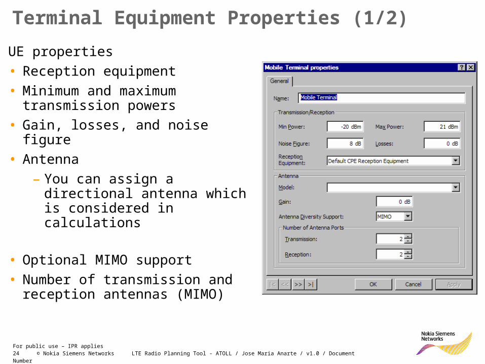
Terminal Equipment Properties (1/2)
UE properties
• Reception equipment
• Minimum and maximum transmission powers
• Gain, losses, and noise figure
• Antenna
– You can assign a directional antenna which is considered in calculations
• Optional MIMO support
• Number of transmission and reception antennas (MIMO)

25 © Nokia Siemens Networks LTE Radio Planning Tool - ATOLL / Jose Maria Anarte / v1.0 / Document NumberFor public use – IPR applies
Terminal Equipment Properties (2/2)
User Properties
• Define service usage characteristics for different types of users
26 © Nokia Siemens Networks LTE Radio Planning Tool - ATOLL / Jose Maria Anarte / v1.0 / Document NumberFor public use – IPR applies
Module Contents
• ATOLL for LTE: Basic Concepts & Settings
• Traffic Modelling
• Monte Carlo Simulations
• MIMO in ATOLL
• Creating Traffic Maps in ATOLL
27 © Nokia Siemens Networks LTE Radio Planning Tool - ATOLL / Jose Maria Anarte / v1.0 / Document NumberFor public use – IPR applies
Live Traffic DataLive Traffic Data
Vector Traffic DataVector Traffic Data
Raster Traffic DataRaster Traffic Data
SubscribersSubscribers
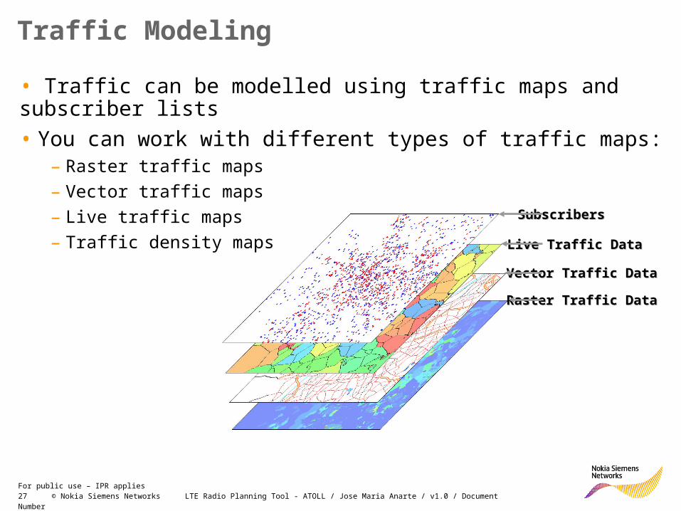
Traffic Modeling
• Traffic can be modelled using traffic maps and subscriber lists
• You can work with different types of traffic maps:– Raster traffic maps
– Vector traffic maps
– Live traffic maps
– Traffic density maps

28 © Nokia Siemens Networks LTE Radio Planning Tool - ATOLL / Jose Maria Anarte / v1.0 / Document NumberFor public use – IPR applies
Subscriber Lists
• Contain lists of fixed subscribers with related parameters
• Used for Fixed Wireless Access (FWA) network design
• Subscriber lists can be created using the mouse or imported from txt or CSV files
• Can be displayed on the map according to different parameters
• Main parameters:– Subscriber ID
– Subscriber Name
– Location: X and Y coordinates
– Height of the antenna
– User profile (services usage)
– Terminal type (can use a directional antenna)
– Serving transmitter and cell (user-defined or calc.)
– Azimuth and downtilt (user-defined or calculated)
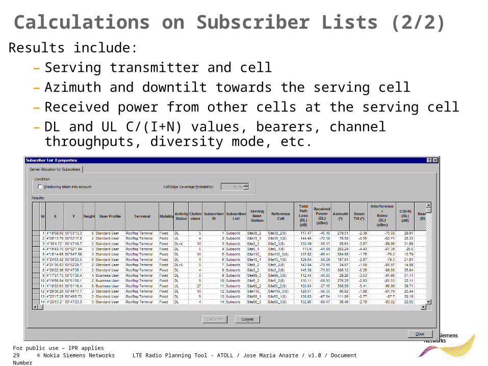
Calculations on Subscriber Lists (1/2)
29 © Nokia Siemens Networks LTE Radio Planning Tool - ATOLL / Jose Maria Anarte / v1.0 / Document NumberFor public use – IPR applies
Calculations on Subscriber Lists (2/2)Results include:
– Serving transmitter and cell
– Azimuth and downtilt towards the serving cell
– Received power from other cells at the serving cell
– DL and UL C/(I+N) values, bearers, channel throughputs, diversity mode, etc.
30 © Nokia Siemens Networks LTE Radio Planning Tool - ATOLL / Jose Maria Anarte / v1.0 / Document NumberFor public use – IPR applies
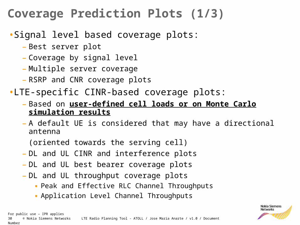
•Signal level based coverage plots:– Best server plot
– Coverage by signal level
– Multiple server coverage
– RSRP and CNR coverage plots
•LTE-specific CINR-based coverage plots:– Based on user-defined cell loads or on Monte Carlo simulation
results
– A default UE is considered that may have a directional antenna
(oriented towards the serving cell)
– DL and UL CINR and interference plots
– DL and UL best bearer coverage plots
– DL and UL throughput coverage plots▪ Peak and Effective RLC Channel Throughputs
▪ Application Level Channel Throughputs
Coverage Prediction Plots (1/3)

31 © Nokia Siemens Networks LTE Radio Planning Tool - ATOLL / Jose Maria Anarte / v1.0 / Document NumberFor public use – IPR applies
Coverage by Signal LevelCoverage by Signal Level
Number of ServersNumber of Servers
Coverage Prediction Examples (2/3)

32 © Nokia Siemens Networks LTE Radio Planning Tool - ATOLL / Jose Maria Anarte / v1.0 / Document NumberFor public use – IPR applies
Coverage by DL CINRCoverage by DL CINR
Coverage by UL CINRCoverage by UL CINR
Coverage Prediction Examples (3/3)
33 © Nokia Siemens Networks LTE Radio Planning Tool - ATOLL / Jose Maria Anarte / v1.0 / Document NumberFor public use – IPR applies
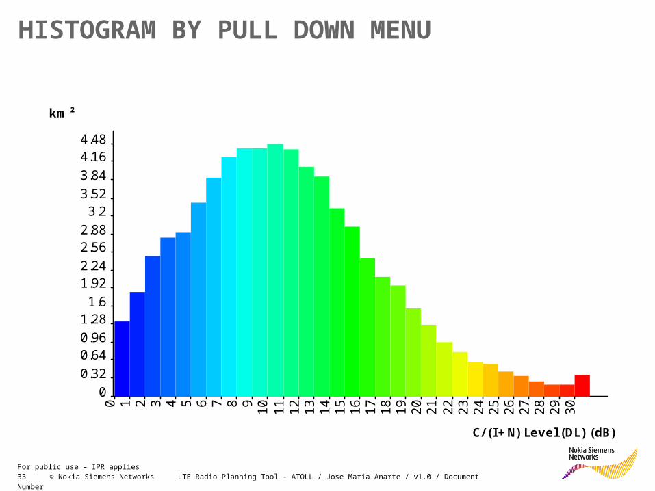
HISTOGRAM BY PULL DOWN MENU
0
0.32
0.640.96
1.281.6
1.922.24
2.562.88
3.23.52
3.84
4.164.48
0 1 2 3 4 5 6 7 8 91
01
11
21
31
41
51
61
71
81
92
02
12
22
32
42
52
62
72
82
93
0
km²
C/ (I+N) Level (DL) (dB)

34 © Nokia Siemens Networks LTE Radio Planning Tool - ATOLL / Jose Maria Anarte / v1.0 / Document NumberFor public use – IPR applies
Module Contents
• ATOLL for LTE: Basic Concepts & Settings
• Traffic Modelling
• Monte Carlo Simulations
• MIMO in ATOLL
• Creating Traffic Maps in ATOLL
35 © Nokia Siemens Networks LTE Radio Planning Tool - ATOLL / Jose Maria Anarte / v1.0 / Document NumberFor public use – IPR applies
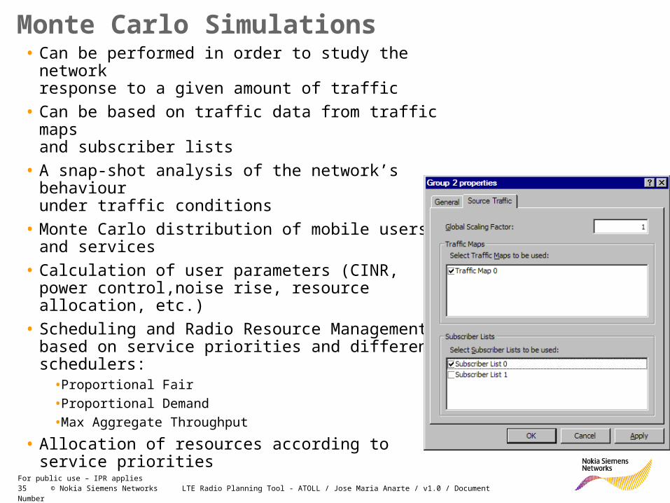
• Can be performed in order to study the networkresponse to a given amount of traffic
• Can be based on traffic data from traffic mapsand subscriber lists
• A snap-shot analysis of the network’s behaviourunder traffic conditions
• Monte Carlo distribution of mobile users and services
• Calculation of user parameters (CINR, power control,noise rise, resource allocation, etc.)
• Scheduling and Radio Resource Managementbased on service priorities and different schedulers:
•Proportional Fair
•Proportional Demand
•Max Aggregate Throughput
• Allocation of resources according to service priorities
Monte Carlo Simulations

36 © Nokia Siemens Networks LTE Radio Planning Tool - ATOLL / Jose Maria Anarte / v1.0 / Document NumberFor public use – IPR applies
•For each cell• UL and DL traffic loads
• UL noise rise
• Calculation of aggregate cell throughputs for UL and DL
(Peak RLC, Effective RLC, and Application Level)
• Other results and statistics
• For each mobile• Serving transmitter and cell
• Azimuth and downtilt (towards the serving cell)
• Received power from and at the serving cell
• DL and UL C/(I+N)
• DL and UL best bearers
• DL and UL channel and user throughputs
• UL transmission power
• Number of used resource blocks in UL
• Other results
Monte Carlo Simulation Results

37 © Nokia Siemens Networks LTE Radio Planning Tool - ATOLL / Jose Maria Anarte / v1.0 / Document NumberFor public use – IPR applies
Monte Carlo Simulation Results Display - mobiles
38 © Nokia Siemens Networks LTE Radio Planning Tool - ATOLL / Jose Maria Anarte / v1.0 / Document NumberFor public use – IPR applies
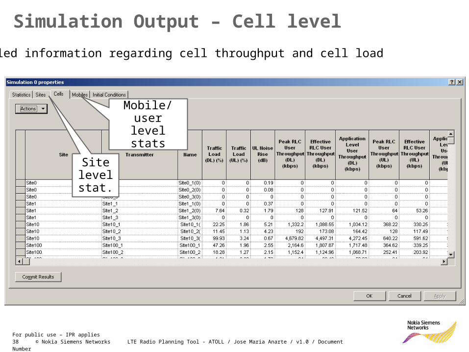
Simulation Output – Cell level
Detailed information regarding cell throughput and cell load
Site level stat.
Mobile/user level stats

39 © Nokia Siemens Networks LTE Radio Planning Tool - ATOLL / Jose Maria Anarte / v1.0 / Document NumberFor public use – IPR applies
Module Contents
• ATOLL for LTE: Basic Concepts & Settings
• Traffic Modelling
• Monte Carlo Simulations
• MIMO in ATOLL
• Creating Traffic Maps in ATOLL

40 © Nokia Siemens Networks LTE Radio Planning Tool - ATOLL / Jose Maria Anarte / v1.0 / Document NumberFor public use – IPR applies
MIMO consideration in ATOLL (TX diversity, non AMS case)•MIMO Gain application in non AMS case
•The gain is applied as correction to the SINR (which is further corrected by clutter specific factor - “Transmit Diversity Gain Offset” [dB] in Clutter Menu). The formula is applied/valid for all SINR. The gain is applied as dB correction to manipulate final SINR further used for bearer assignment.
•Same construction is used in UL and DL. However, tool allows to enter different values to specify UL and DL.
41 © Nokia Siemens Networks LTE Radio Planning Tool - ATOLL / Jose Maria Anarte / v1.0 / Document NumberFor public use – IPR applies
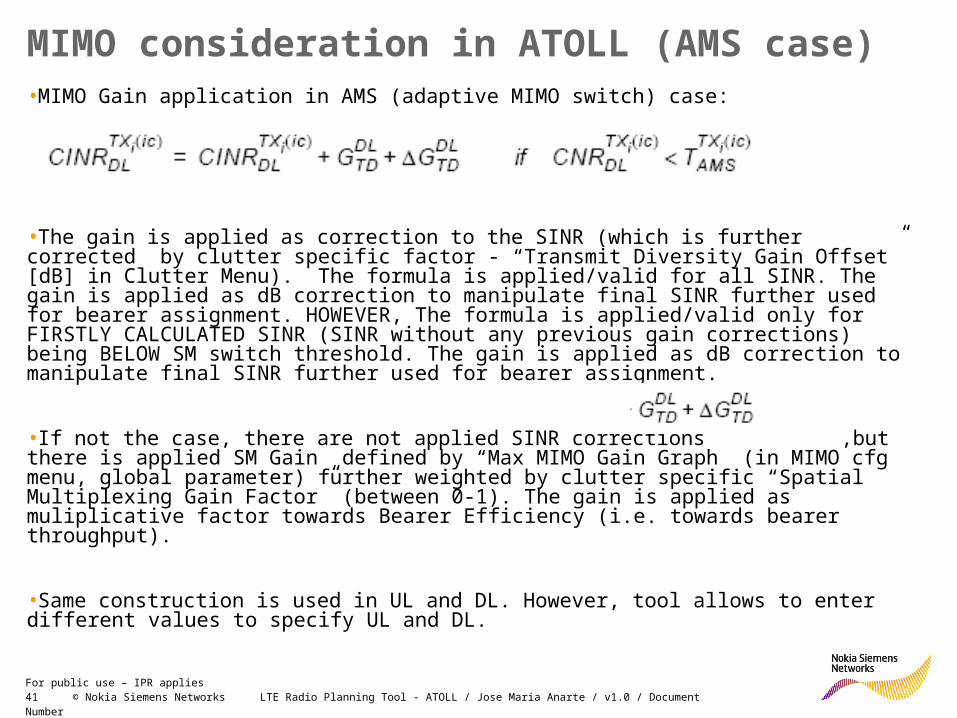
MIMO consideration in ATOLL (AMS case)•MIMO Gain application in AMS (adaptive MIMO switch) case:
•The gain is applied as correction to the SINR (which is further corrected by clutter specific factor - “Transmit Diversity Gain Offset” [dB] in Clutter Menu). The formula is applied/valid for all SINR. The gain is applied as dB correction to manipulate final SINR further used for bearer assignment. HOWEVER, The formula is applied/valid only for FIRSTLY CALCULATED SINR (SINR without any previous gain corrections) being BELOW SM switch threshold. The gain is applied as dB correction to manipulate final SINR further used for bearer assignment.
•If not the case, there are not applied SINR corrections ,but there is applied SM Gain defined by “Max MIMO Gain Graph” (in MIMO cfg menu, global parameter) further weighted by clutter specific “Spatial Multiplexing Gain Factor” (between 0-1). The gain is applied as muliplicative factor towards Bearer Efficiency (i.e. towards bearer throughput).
•Same construction is used in UL and DL. However, tool allows to enter different values to specify UL and DL.
42 © Nokia Siemens Networks LTE Radio Planning Tool - ATOLL / Jose Maria Anarte / v1.0 / Document NumberFor public use – IPR applies
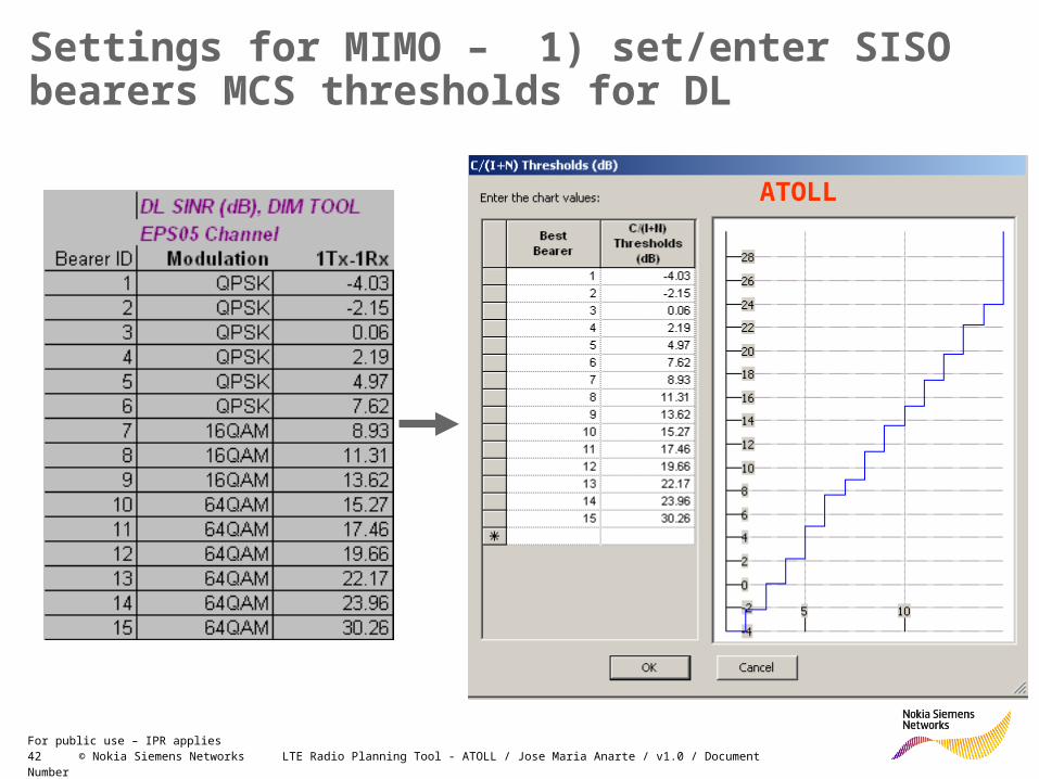
Settings for MIMO – 1) set/enter SISO bearers MCS thresholds for DL
ATOLL
43 © Nokia Siemens Networks LTE Radio Planning Tool - ATOLL / Jose Maria Anarte / v1.0 / Document NumberFor public use – IPR applies
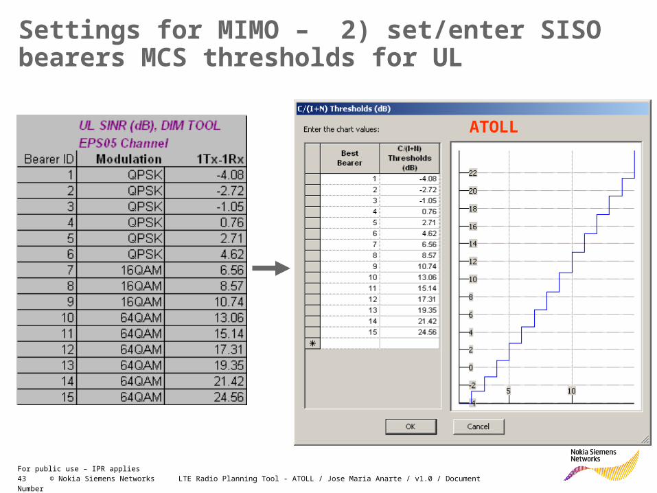
Settings for MIMO – 2) set/enter SISO bearers MCS thresholds for UL
ATOLL
44 © Nokia Siemens Networks LTE Radio Planning Tool - ATOLL / Jose Maria Anarte / v1.0 / Document NumberFor public use – IPR applies
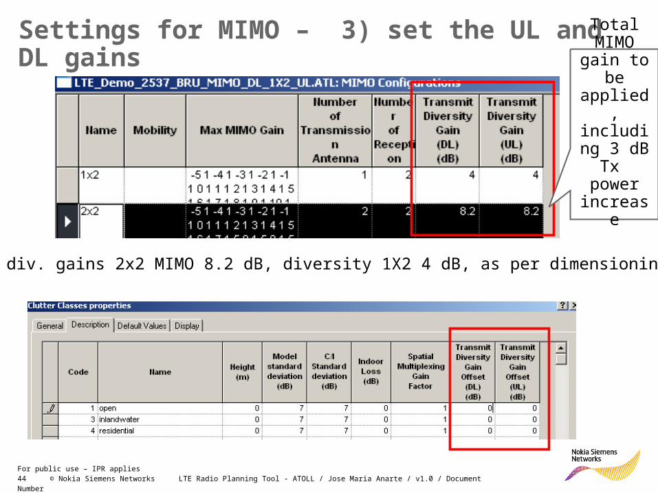
Settings for MIMO – 3) set the UL and DL gains
Default div. gains 2x2 MIMO 8.2 dB, diversity 1X2 4 dB, as per dimensioning tool
Total MIMO
gain to be applied, including 3 dB Tx power
increase

45 © Nokia Siemens Networks LTE Radio Planning Tool - ATOLL / Jose Maria Anarte / v1.0 / Document NumberFor public use – IPR applies
Setting of MIMO 4) with SM (Adaptive MIMO Switch)•Value of AMS switch have to be entered •Cell to be AMS enabled (“Diversity Support)
•Proposed default 15dB or higher (LTE Performance SFS speaking about SM with connection of 64QAM modulation, which might appear for SINR above 15dB, however value around 22-23dB is more realistic).
46 © Nokia Siemens Networks LTE Radio Planning Tool - ATOLL / Jose Maria Anarte / v1.0 / Document NumberFor public use – IPR applies
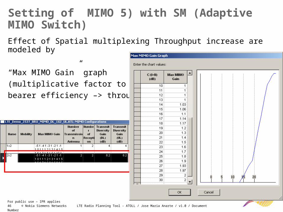
Setting of MIMO 5) with SM (Adaptive MIMO Switch)Effect of Spatial multiplexing Throughput increase are modeled by
“Max MIMO Gain” graph
(multiplicative factor to weight
bearer efficiency –> throughput)
47 © Nokia Siemens Networks LTE Radio Planning Tool - ATOLL / Jose Maria Anarte / v1.0 / Document NumberFor public use – IPR applies
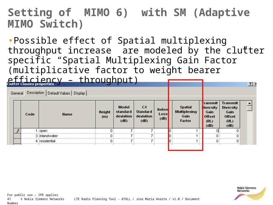
Setting of MIMO 6) with SM (Adaptive MIMO Switch)
•Possible effect of Spatial multiplexing throughput increase are modeled by the clutter specific “Spatial Multiplexing Gain Factor” (multiplicative factor to weight bearer efficiency – throughput)

48 © Nokia Siemens Networks LTE Radio Planning Tool - ATOLL / Jose Maria Anarte / v1.0 / Document NumberFor public use – IPR applies
Settings for MIMO – 7) Condition MIMO to be used
User have to use MIMO feature
MIMO terminal to be defined 2 RX and 1TX antenna to have DL MIMO (2x2) and UL TX diversity - SIMO (1x2)

49 © Nokia Siemens Networks LTE Radio Planning Tool - ATOLL / Jose Maria Anarte / v1.0 / Document NumberFor public use – IPR applies
MIMO INPUT VALUES – SUMMARY•KEEP THE VALUES IN LINE WITH DIMENSIONING TOOL, so….•UL noise figure (BTS) 2.2 dB•DL noise figure (UE) 7dB•Default div. gains
– diversity (1X2): 4 dB – MIMO (2x2): 8.2 dB – consists of 4 dB reception diversity, 3 dB TX power
increase and 1.2 dB MIMO receiving gain over reception diversity.
•Clutter specific offsets 0dB (i.e. no impact)•MAX MIMO GAIN (Capacity gain due to SM) – between 1(no capacity gain) and 2(doubling capacity), so about 1.5.•Clutter specific offset 1 (i.e. no impact)•Adaptive MIMO Switch Threshold cca 15dB (LTE Performance SFS speaking about SM with connection of 64QAM modulation, which might appear for SINR above 15dB, however value around 22-23dB is more realistic)•LTE Bearers as per NSN dimensioning tool•UL and DL MCS thresholds as per NSN dimensioning tool (EPS05 Channel, column for SISO (1x1))

50 © Nokia Siemens Networks LTE Radio Planning Tool - ATOLL / Jose Maria Anarte / v1.0 / Document NumberFor public use – IPR applies
MIMO LIMITATION WITH CURRENT ATOLL - FORSK COMMENTS (NOV 2008)
•In the current version of Atoll, AMS (Adaptive MIMO Switch) Threshold is applied on UL and DL in any configuration……
•In the commercial version of the LTE Module (Atoll 2.8.0 - end of 2008), it will be possible to set MIMO configurations (STTD, SM, AMS, none) on DL or UL independently.
•That's partially why the current version is just a "beta / pre-release" LTE version.
•NOTE – commercial version without the above limitation from 1Q09
51 © Nokia Siemens Networks LTE Radio Planning Tool - ATOLL / Jose Maria Anarte / v1.0 / Document NumberFor public use – IPR applies
Module Contents
• ATOLL for LTE: Basic Concepts & Settings
• Traffic Modelling
• Monte Carlo Simulations
• MIMO in ATOLL
• Creating Traffic Maps in ATOLL

52 © Nokia Siemens Networks LTE Radio Planning Tool - ATOLL / Jose Maria Anarte / v1.0 / Document NumberFor public use – IPR applies
Creating Traffic Map in ATOLL
1. Create a new traffic map: "Map based on environments"
2. Then select in the toolbox a type of environment, “dense urban" for example and draw a polygon. Hit "close"
3. Go to the data tab and edit the environment in the LTE parameters folder. On the second tab, you have "clutter weighting". Here you can set up a weighting based on clutter classes
4. At this moment traffic map have been created and the clutter weighting set here will be taken into account during any calculations.
5. Map is there and is possible to use for simulations, but it is invisible on GUI window as map. To see the map it is necessary to export and import the map – see next slide.

53 © Nokia Siemens Networks LTE Radio Planning Tool - ATOLL / Jose Maria Anarte / v1.0 / Document NumberFor public use – IPR applies
Visualization of created traffic map
1. Go back to the geo tab, right click on traffic folder then "export cumulated traffic".
2. Select a format (bil for example)
3. Then you can choose the export zone (entire area or computation zone) and the traffic map you wish to export.
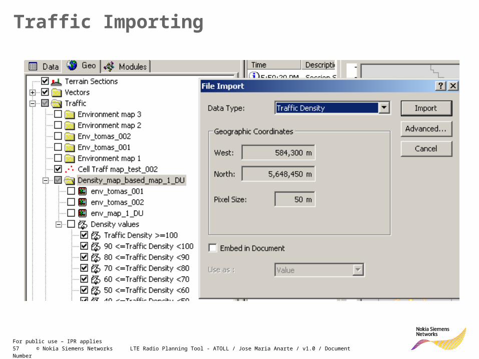
4. If you want to really see the result, you have now to import the traffic map.
5. File / import and the select traffic density as map type.
54 © Nokia Siemens Networks LTE Radio Planning Tool - ATOLL / Jose Maria Anarte / v1.0 / Document NumberFor public use – IPR applies
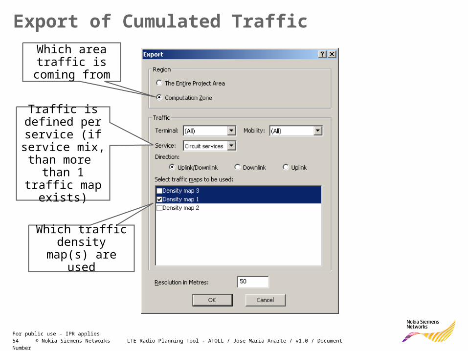
Export of Cumulated Traffic
Which area traffic is coming
from
Which traffic density map(s)
are used
Traffic is defined per service (if
service mix, than more than
1 traffic map exists)
55 © Nokia Siemens Networks LTE Radio Planning Tool - ATOLL / Jose Maria Anarte / v1.0 / Document NumberFor public use – IPR applies
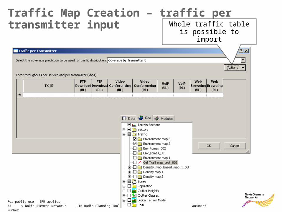
Traffic Map Creation – traffic per transmitter inputWhole traffic table is
possible to import
56 © Nokia Siemens Networks LTE Radio Planning Tool - ATOLL / Jose Maria Anarte / v1.0 / Document NumberFor public use – IPR applies
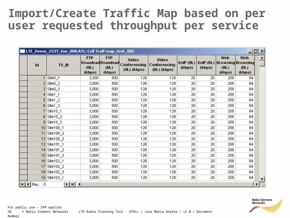
Import/Create Traffic Map based on per user requested throughput per service
57 © Nokia Siemens Networks LTE Radio Planning Tool - ATOLL / Jose Maria Anarte / v1.0 / Document NumberFor public use – IPR applies
Traffic Importing

58 © Nokia Siemens Networks LTE Radio Planning Tool - ATOLL / Jose Maria Anarte / v1.0 / Document NumberFor public use – IPR applies
Imported Traffic – distribution between terminal type, mobility and indoor/outdoor percentage

59 © Nokia Siemens Networks LTE Radio Planning Tool –ATOLL / Jose Maria Anarte / v1.0 / Document NumberFor public use – IPR applies
Appendix
60 © Nokia Siemens Networks LTE Radio Planning Tool - ATOLL / Jose Maria Anarte / v1.0 / Document NumberFor public use – IPR applies
Notes
Following topics are suitable to be moved to the appendix area:
1.- MIMO in ATOLL
2.- Creating Traffic Maps in ATOLL