lte ppt
TRANSCRIPT
Long Term EvolutionLong Term Evolution
Poonam BhagatM.E Computer

2
What is LTE?What is LTE?
• LTE stands for Long Term Evolution
• LTE is a next –generation broadband network technology beyond 3G developed by the Third Generation Partnership Project (3GPP).
• Promises data transfer rates of 100Mbps
• Based on UMTS 3G technology
• Optimized for All-IP traffic

3
Evolution of Radio Access Evolution of Radio Access TechnologiesTechnologies
14.4 Kbps
14.4 Mbps
115 Mbps
1 Gbps
4
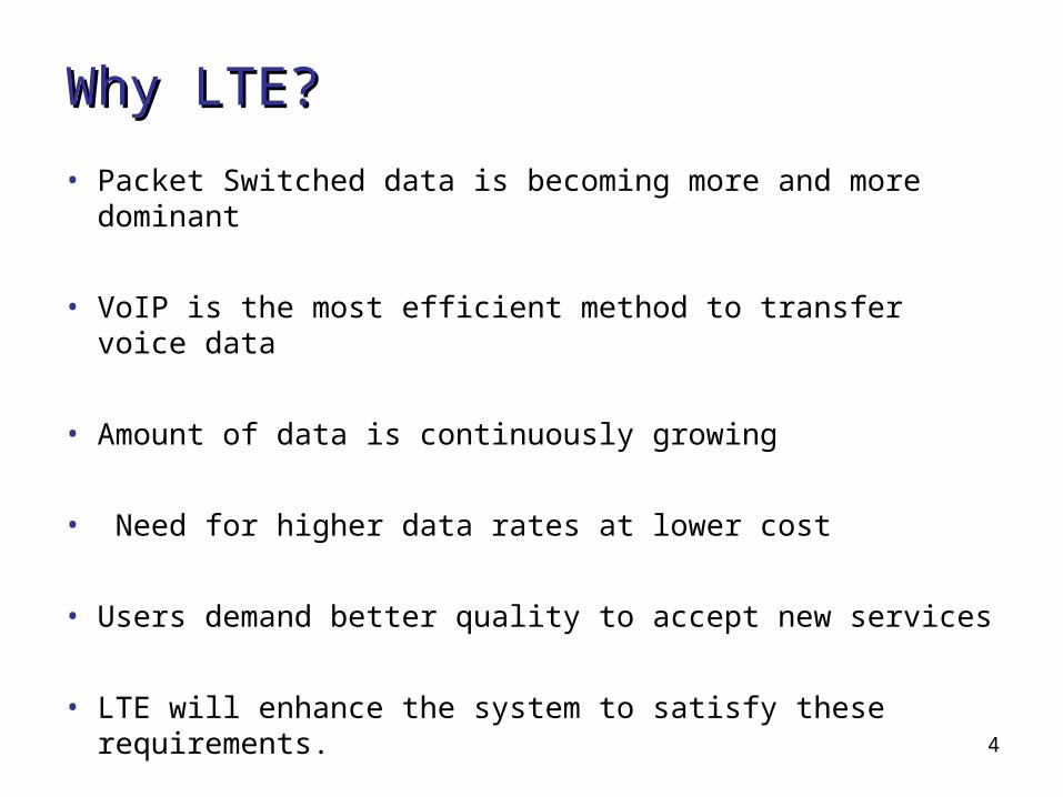
WhyWhy LTE?LTE?
• Packet Switched data is becoming more and more dominant
• VoIP is the most efficient method to transfer voice data
• Amount of data is continuously growing
• Need for higher data rates at lower cost
• Users demand better quality to accept new services
• LTE will enhance the system to satisfy these requirements.
5
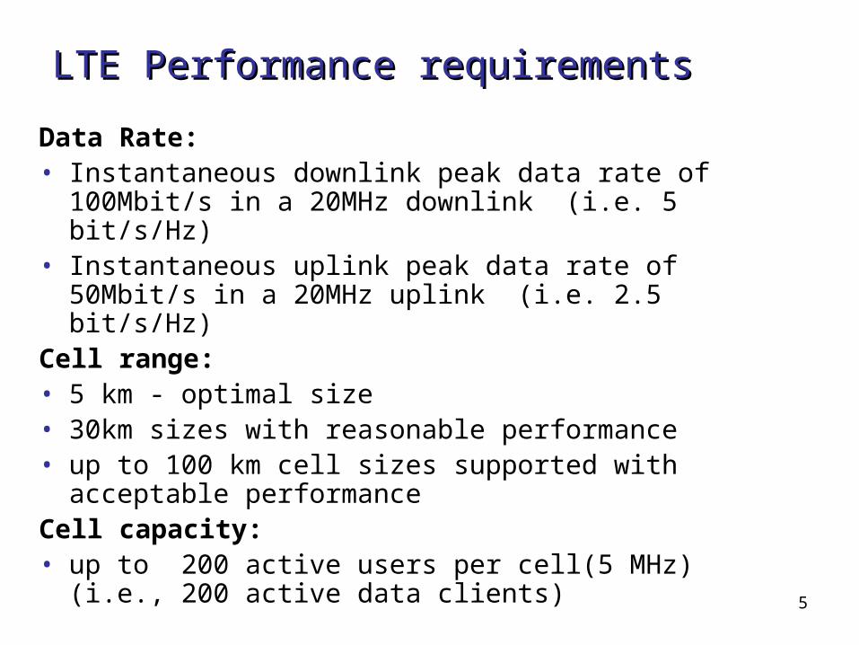
LTE Performance requirementsLTE Performance requirements
Data Rate:• Instantaneous downlink peak data rate of
100Mbit/s in a 20MHz downlink (i.e. 5 bit/s/Hz)• Instantaneous uplink peak data rate of 50Mbit/s
in a 20MHz uplink (i.e. 2.5 bit/s/Hz) Cell range:• 5 km - optimal size• 30km sizes with reasonable performance• up to 100 km cell sizes supported with acceptable
performanceCell capacity:• up to 200 active users per cell(5 MHz) (i.e., 200
active data clients)
6
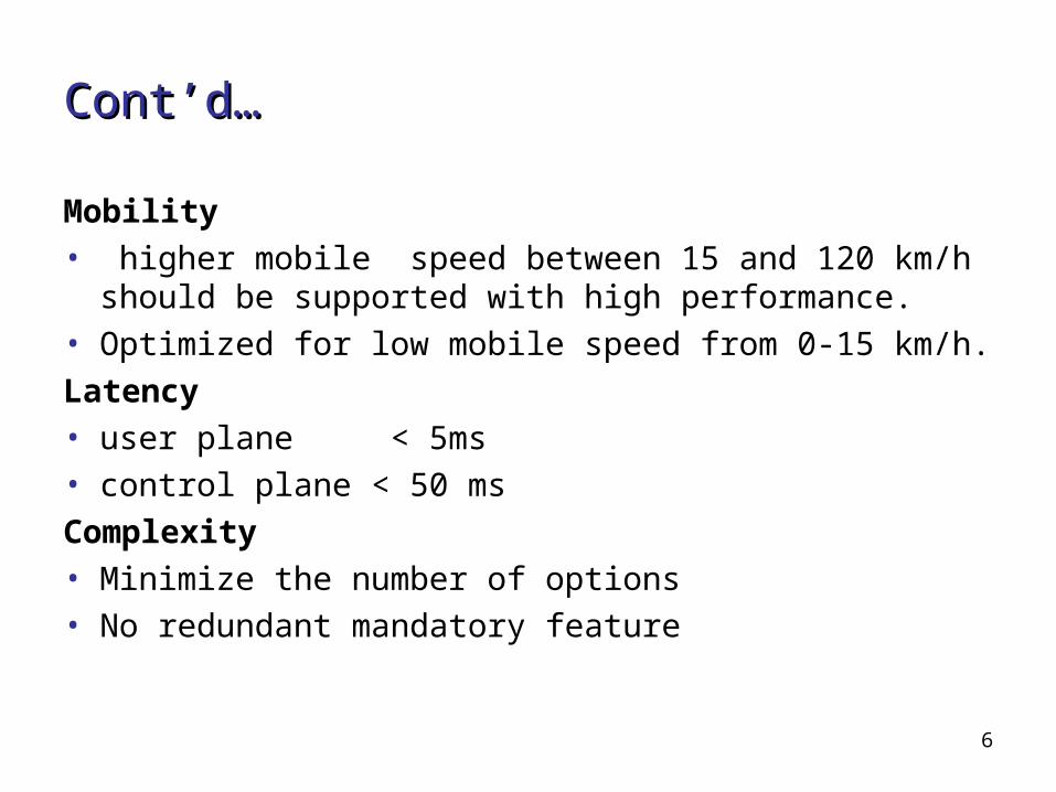
Cont’d…Cont’d…
Mobility • higher mobile speed between 15 and 120 km/h
should be supported with high performance.• Optimized for low mobile speed from 0-15 km/h.Latency • user plane < 5ms• control plane < 50 msComplexity• Minimize the number of options• No redundant mandatory feature
7
Advantages of LTE for Network Advantages of LTE for Network OperatorOperator
• High network throughput• Increased data transfer speed• Provides Low latency• Most Cost effectiveness• Simplified upgrade path from 3G networks

8
Advantages of LTE for End UsersAdvantages of LTE for End Users
• Faster data downloads/uploads• Improved response for applications• Improved end-user experience
9
LTE TechnologiesLTE Technologies
• Uses Orthogonal Frequency Division Multiplexing Orthogonal Frequency Division Multiplexing (OFDM) for downlink
• Uses Single Carrier -Frequency Division Multiple Single Carrier -Frequency Division Multiple AccessAccess (SC-FDMA) for uplink
• Uses Multiple Input Multiple Output Multiple Input Multiple Output (MIMO)
• Uses System Architecture Evolution System Architecture Evolution (SAE)
10
OFDMOFDM
• LTE uses OFDM for the downlink – from the base station to the terminal.
• OFDM meets the LTE requirement for spectrum flexibility and enables cost-efficient solutions for very wide carriers with high peak rates.
• OFDM uses a large number of narrow sub-carriers for multi-carrier transmission.
• In the frequency domain, the spacing between the subcarriers, Δf, is 15kHz.The cyclic prefix is used to maintain orthogonality between the sub-carriers even for a time-dispersive radio channel.
11
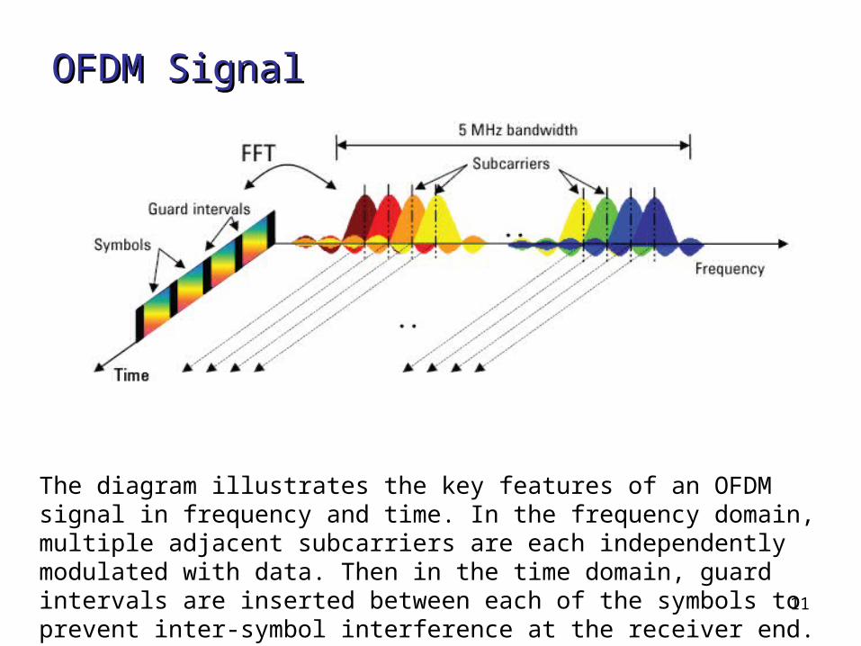
OFDMOFDM SignalSignal
The diagram illustrates the key features of an OFDM signal in frequency and time. In the frequency domain, multiple adjacent subcarriers are each independently modulated with data. Then in the time domain, guard intervals are inserted between each of the symbols to prevent inter-symbol interference at the receiver end.
12
SC-FDMASC-FDMA
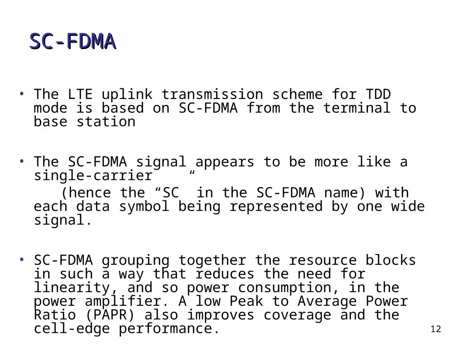
• The LTE uplink transmission scheme for TDD mode is based on SC-FDMA from the terminal to base station
• The SC-FDMA signal appears to be more like a single-carrier
(hence the “SC” in the SC-FDMA name) with each data symbol being represented by one wide signal.
• SC-FDMA grouping together the resource blocks in such a way that reduces the need for linearity, and so power consumption, in the power amplifier. A low Peak to Average Power Ratio (PAPR) also improves coverage and the cell-edge performance.

13
SC-FDMA SignalSC-FDMA Signal
After SC-FDMA symbol period has elapsed, the CP is inserted and the next four symbols are transmitted in series.The CP is shown as a gap; however, it is actually filled with acopy of the end of the next symbol, which means that the transmission power iscontinuous but has a phase discontinuity at the symbol boundary.

14
MIMOMIMO
• MIMO systems form an essential part of LTE in order to achieve the requirements for throughput and spectral efficiency.
• MIMO employs multiple transmit and receive antennas to substantially enhance the air interface.
• MIMO processing also exploits spatial multiplexing, allowing different data streams to be transmitted simultaneously from the different transmit antennas, to increase the end-user data rate and cell capacity.
• MIMO can also implement beam-forming to further increase available data rates and spectrum efficiency

15
Advanced Antenna TechniquesAdvanced Antenna Techniques
• Single data stream / user• Beam-forming Coverage, longer battery life
• Spatial Division Multiple Access (SDMA)
Multiple users in same radio resource
• Multiple data stream / user Diversity
Link robustness
• Spatial multiplexing Spectral efficiency, high data rate
support
16
SAESAE
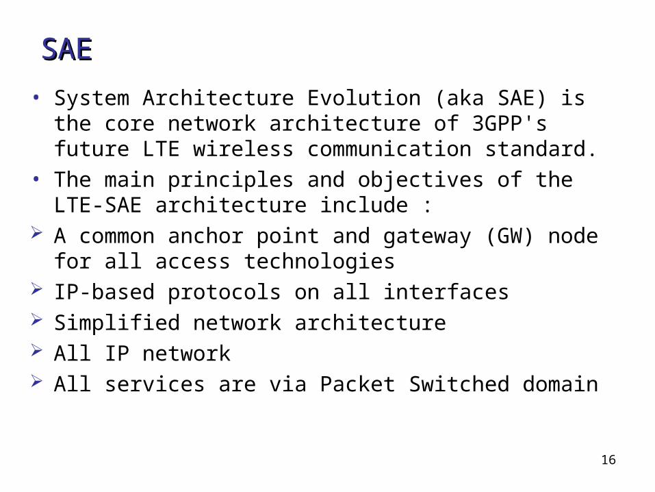
• System Architecture Evolution (aka SAE) is the core network architecture of 3GPP's future LTE wireless communication standard.
• The main principles and objectives of the LTE-SAE architecture include :
A common anchor point and gateway (GW) node for all access technologies
IP-based protocols on all interfaces Simplified network architecture All IP network All services are via Packet Switched domain
17
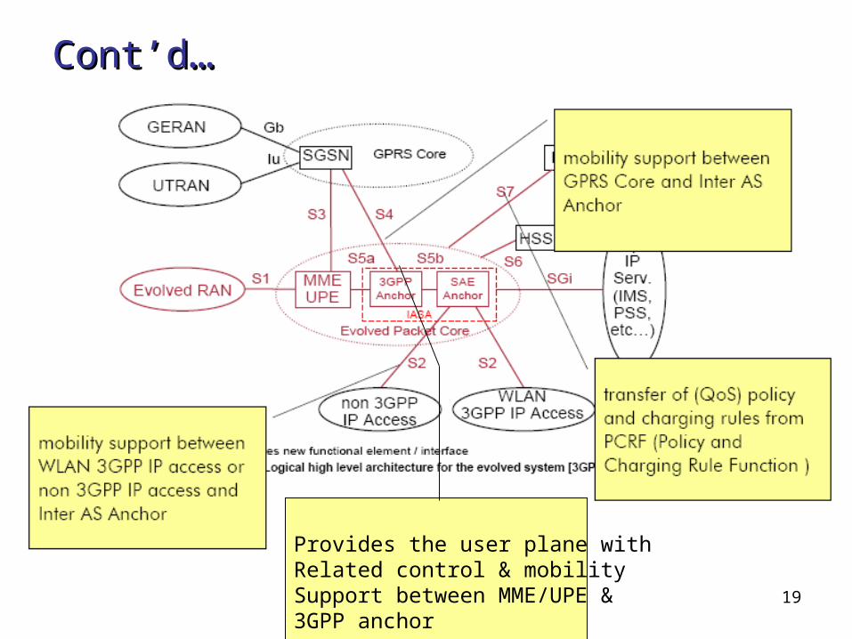
LTE and SAELTE and SAE
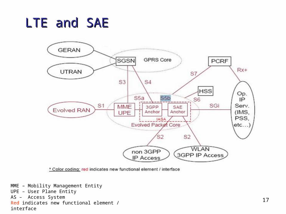
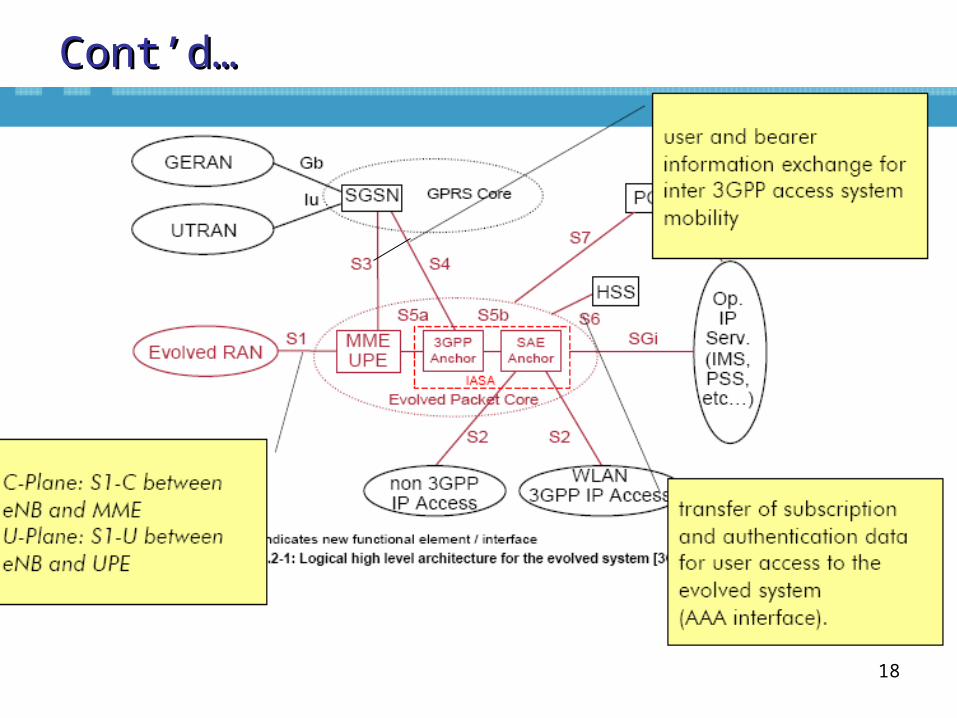
MME – Mobility Management Entity UPE – User Plane EntityAS – Access SystemRed indicates new functional element / interface
18
Cont’d…Cont’d…
19
Cont’dCont’d……
Provides the user plane withRelated control & mobility Support between MME/UPE &3GPP anchor

20
Evolved Packet Core (EPC)Evolved Packet Core (EPC)
• MME (Mobility Management Entity): Manages and stores the UE control plane context,
generates temporary Id, provides UE authentication, authorization, mobility management
• UPE (User Plane Entity): Manages and stores UE context, ciphering, mobility
anchor, packet routing and forwarding, initiation of paging
21
Cont’d… Cont’d…
• 3GPP anchor: Mobility anchor between 2G/3G and LTE• SAE anchor: Mobility anchor between 3GPP and non 3GPP (I-
WLAN, etc)
22
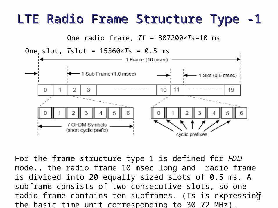
LTE Radio Frame Structure Type -1LTE Radio Frame Structure Type -1
For the frame structure type 1 is defined for FDD mode., the radio frame 10 msec long and radio frame is divided into 20 equally sized slots of 0.5 ms. A subframe consists of two consecutive slots, so one radio frame contains ten subframes. (Ts is expressing the basic time unit corresponding to 30.72 MHz).
One radio frame, Tf = 307200×Ts=10 ms
One slot, Tslot = 15360×Ts = 0.5 ms
23
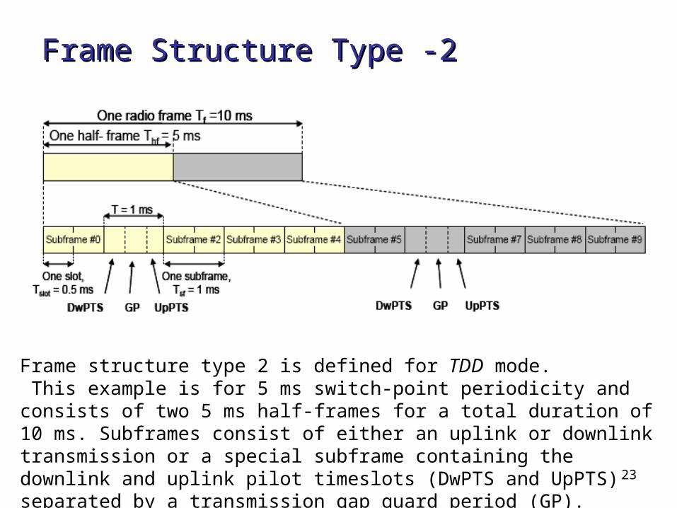
Frame Structure Type -2Frame Structure Type -2
Frame structure type 2 is defined for TDD mode. This example is for 5 ms switch-point periodicity and consists of two 5 ms half-frames for a total duration of 10 ms. Subframes consist of either an uplink or downlink transmission or a special subframe containing the downlink and uplink pilot timeslots (DwPTS and UpPTS) separated by a transmission gap guard period (GP).
24
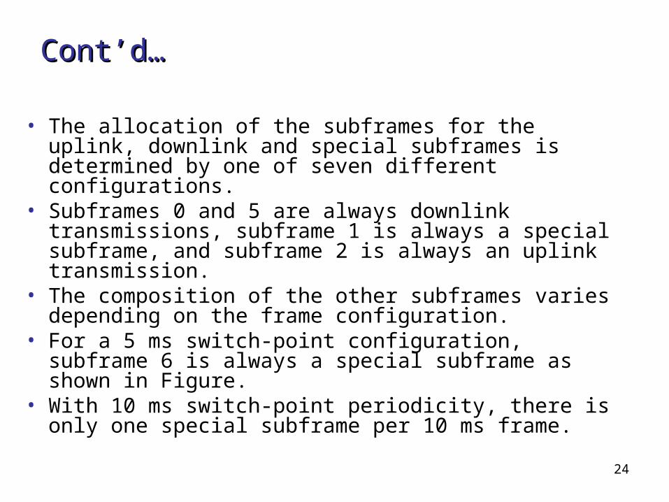
Cont’d…Cont’d…
• The allocation of the subframes for the uplink, downlink and special subframes is determined by one of seven different configurations.
• Subframes 0 and 5 are always downlink transmissions, subframe 1 is always a special subframe, and subframe 2 is always an uplink transmission.
• The composition of the other subframes varies depending on the frame configuration.
• For a 5 ms switch-point configuration, subframe 6 is always a special subframe as shown in Figure.
• With 10 ms switch-point periodicity, there is only one special subframe per 10 ms frame.
25
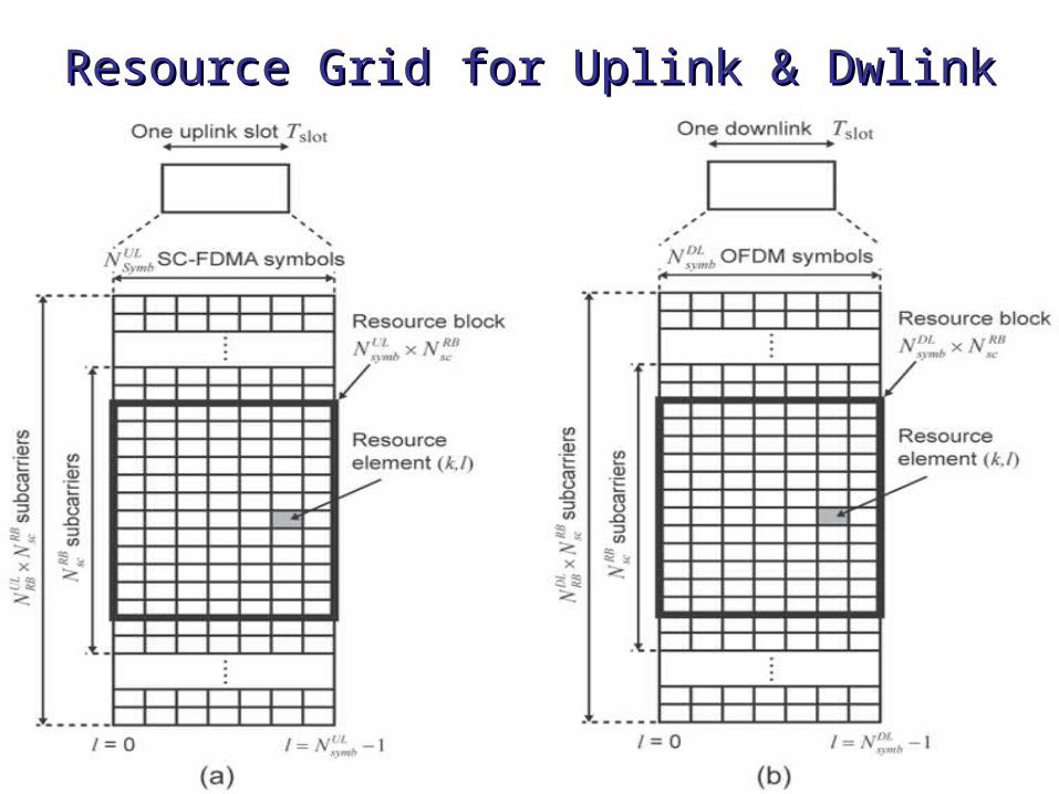
Resource Grid for Uplink & DwlinkResource Grid for Uplink & Dwlink
26
Cont’d…Cont’d…
• A resource element is the smallest unit in the physical layer and occupies one
• OFDM or SC-FDMA symbol in the time domain and one subcarrier in the frequency domain.
• A resource block (RB) is the smallest unit that can be scheduled for transmission.
• An RB physically occupies 0.5 ms (1 slot) in the time domain and 180 kHz in the frequency domain. The number of subcarriers per RB and the number of symbols per RB vary as a function of the cyclic prefix length and subcarrier spacing,
27
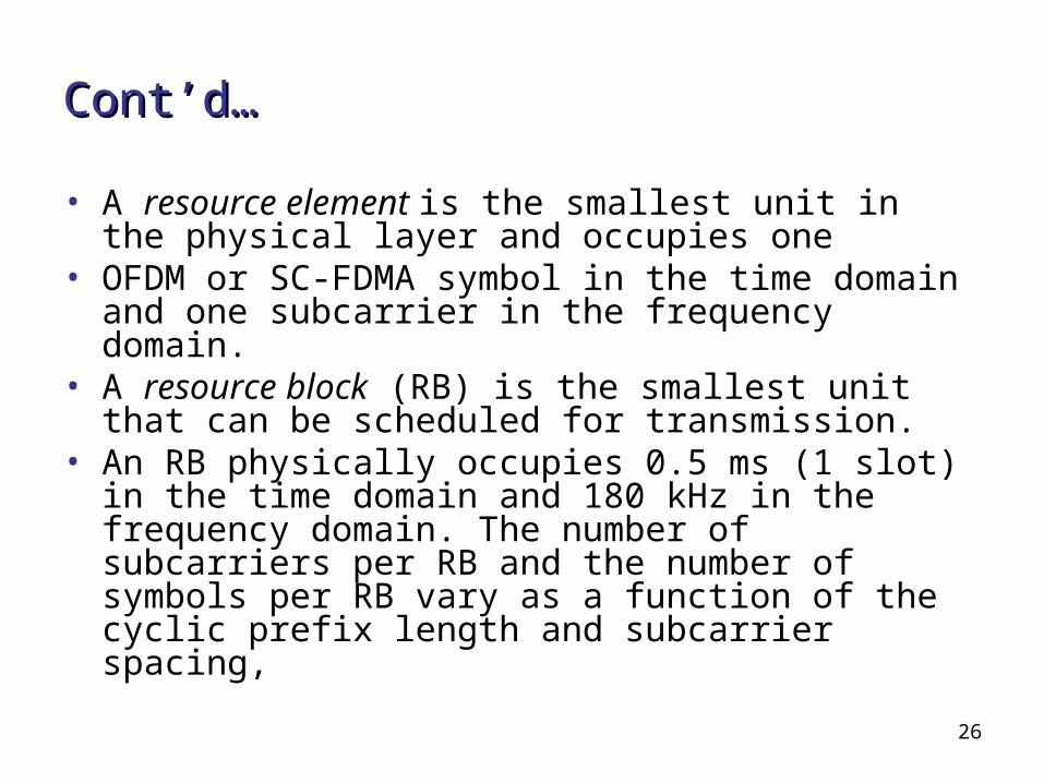
LTE Downlink ChannelsLTE Downlink Channels
• Transport channels The number of transport channels has been
reduced to reduce complexity of the LTE protocol architecture.This is mainly due to the focus on shared channel operation, i.e. no dedicated channels are used any more.
• Logical channels Logical channels can be classified in control and
traffic channels.
Control Channels (for the transfer of control plane information only)
Traffic Channels (for the transfer of user plane information only)
28
Cont’d…Cont’d…
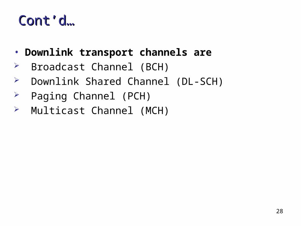
• Downlink transport channels are Broadcast Channel (BCH) Downlink Shared Channel (DL-SCH) Paging Channel (PCH) Multicast Channel (MCH)
29
Cont’d…Cont’d…
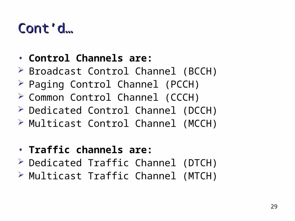
• Control Channels are: Broadcast Control Channel (BCCH) Paging Control Channel (PCCH) Common Control Channel (CCCH) Dedicated Control Channel (DCCH) Multicast Control Channel (MCCH)
• Traffic channels are: Dedicated Traffic Channel (DTCH) Multicast Traffic Channel (MTCH)

30
Cont’d…Cont’d…
• Downlink Physical Channels are: Physical Broadcast Channel (PBCH) Physical Multicast Channel (PMCH) Physical Downlink Control Channel (PDCCH) Physical Downlink Shared Channel (PDSCH) Physical Control Format Indicator Channel
(PCFICH) Physical Hybrid ARQ Indicator Channel (PHICH)
31
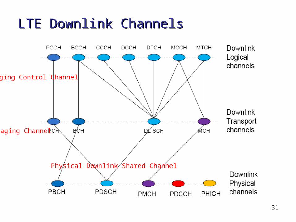
LTE Downlink ChannelsLTE Downlink Channels
Paging Channel
Paging Control Channel
Physical Downlink Shared Channel
32
LTE Uplink ChannelsLTE Uplink Channels
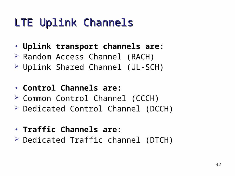
• Uplink transport channels are: Random Access Channel (RACH) Uplink Shared Channel (UL-SCH)
• Control Channels are: Common Control Channel (CCCH) Dedicated Control Channel (DCCH)
• Traffic Channels are: Dedicated Traffic channel (DTCH)
33
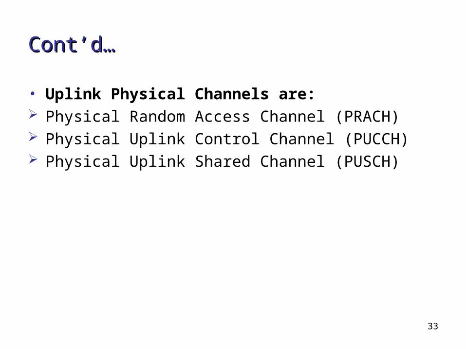
Cont’d…Cont’d…
• Uplink Physical Channels are: Physical Random Access Channel (PRACH) Physical Uplink Control Channel (PUCCH) Physical Uplink Shared Channel (PUSCH)
34
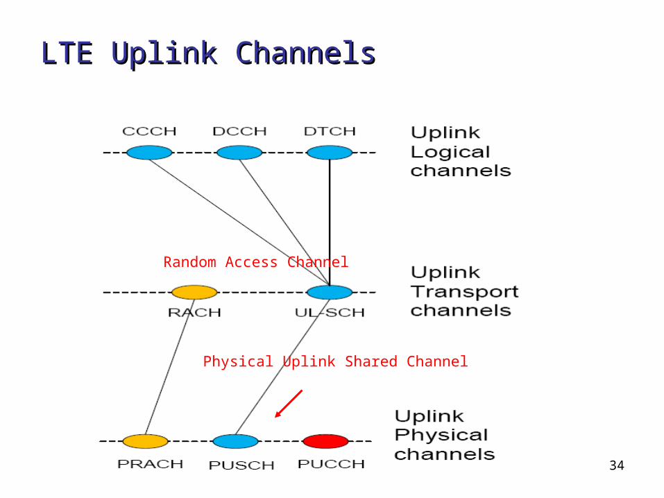
LTE Uplink ChannelsLTE Uplink Channels
Random Access Channel
Physical Uplink Shared Channel
35
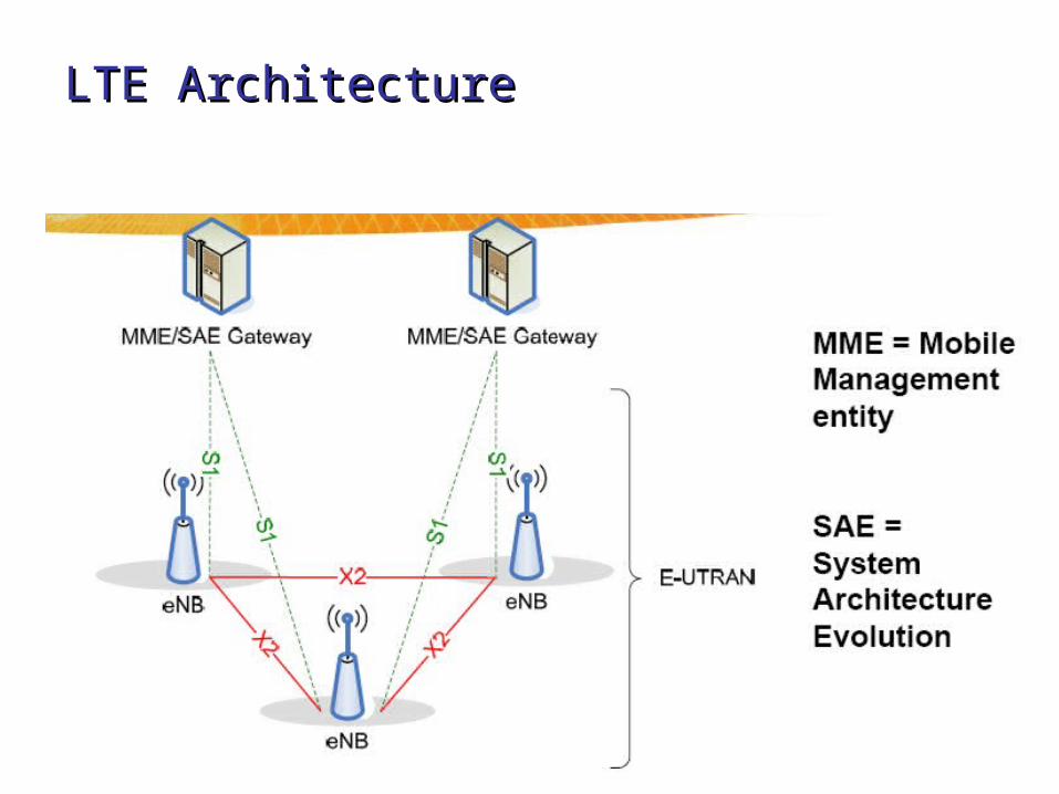
LTE ArchitectureLTE Architecture

36
eNB FunctionseNB Functions
• Radio Resource Management: • Radio Bearer Control, Radio Admission Control,
Connection• Mobility Control, Dynamic allocation of resources to
UEs in both UL and DL (scheduling);• IP header compression and encryption of user data
stream;• Selection of an MME at UE attachment when no
routing to an MME can be determined from the information provided by the UE;
• Routing of User Plane data towards Serving Gateway;• Scheduling and transmission of paging messages
(from the MME);• Scheduling and transmission of broadcast information
(from the MME or O&M);• Measurement and reporting for mobility and
scheduling.
37
MME FunctionsMME Functions
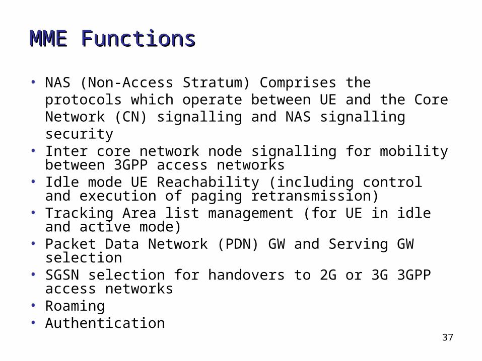
• NAS (Non-Access Stratum) Comprises the protocols which operate between UE and the Core Network (CN) signalling and NAS signalling security
• Inter core network node signalling for mobility between 3GPP access networks
• Idle mode UE Reachability (including control and execution of paging retransmission)
• Tracking Area list management (for UE in idle and active mode)
• Packet Data Network (PDN) GW and Serving GW selection
• SGSN selection for handovers to 2G or 3G 3GPP access networks
• Roaming• Authentication

38
S1 and X2S1 and X2
• X2 user plane Non-guaranteed delivery of user plane PDU’sIP
transport GTP-U on top of UDP/IP• X2 control plane Guaranteed delivery of control plane PDU’s SCTP on top of IP for improved reliability of
application layer messaging• S1 key functions Inter-3GPP-RAT Handovers Intra LTE Handovers Initial context setup, modification and release
initiated by MME Security and roaming UE capability and identification Paging
39
LTE Protocol StackLTE Protocol Stack
• Data Flow through the UE LTE stack• PHY function
40
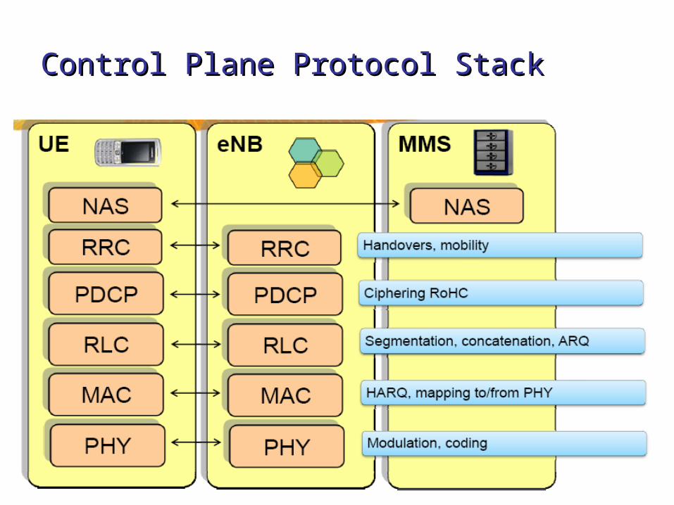
Control Plane Protocol Stack Control Plane Protocol Stack

41
Cont’d…Cont’d…
• The main services and functions of PDCP for the control plane include:
-Ciphering and Integrity Protection• Transfer of control plane data between RRC and
RLC layers.
42
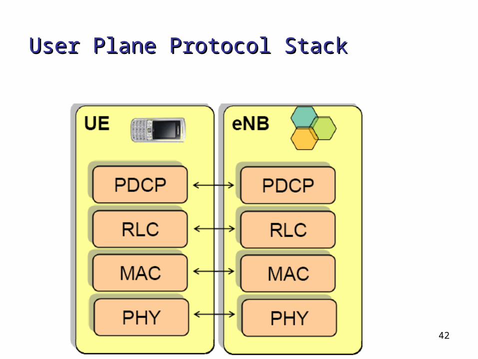
User Plane Protocol StackUser Plane Protocol Stack
43
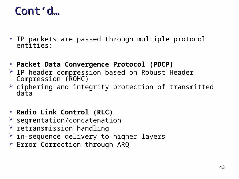
Cont’d…Cont’d…
• IP packets are passed through multiple protocol entities:
• Packet Data Convergence Protocol (PDCP) IP header compression based on Robust Header
Compression (ROHC) ciphering and integrity protection of transmitted data
• Radio Link Control (RLC) segmentation/concatenation retransmission handling in-sequence delivery to higher layers Error Correction through ARQ
44
Cont’d…Cont’d…
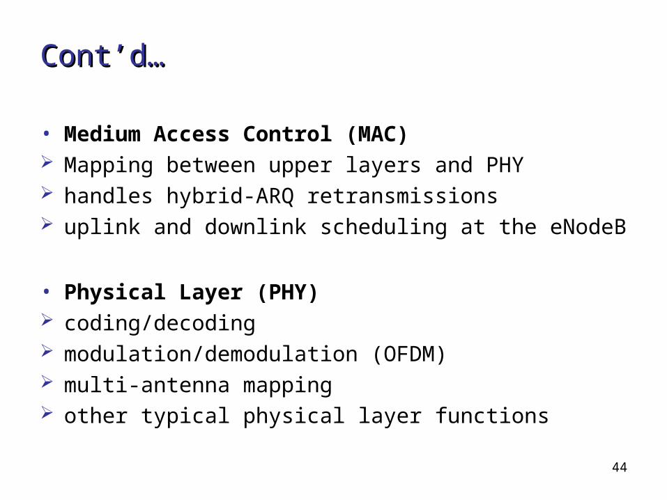
• Medium Access Control (MAC) Mapping between upper layers and PHY handles hybrid-ARQ retransmissions uplink and downlink scheduling at the eNodeB
• Physical Layer (PHY) coding/decoding modulation/demodulation (OFDM) multi-antenna mapping other typical physical layer functions

45
Security features in the LTE-SAE Security features in the LTE-SAE NetworkNetwork• Five security feature groups: • Network access security
provides users with secure access to services protects against attacks on the access
interface• Network domain security
enables nodes to exchange signalling- & user- data securely
protects against attacks on the wire line network
• User domain security Provides secure access to mobile stations
46
Cont’d…
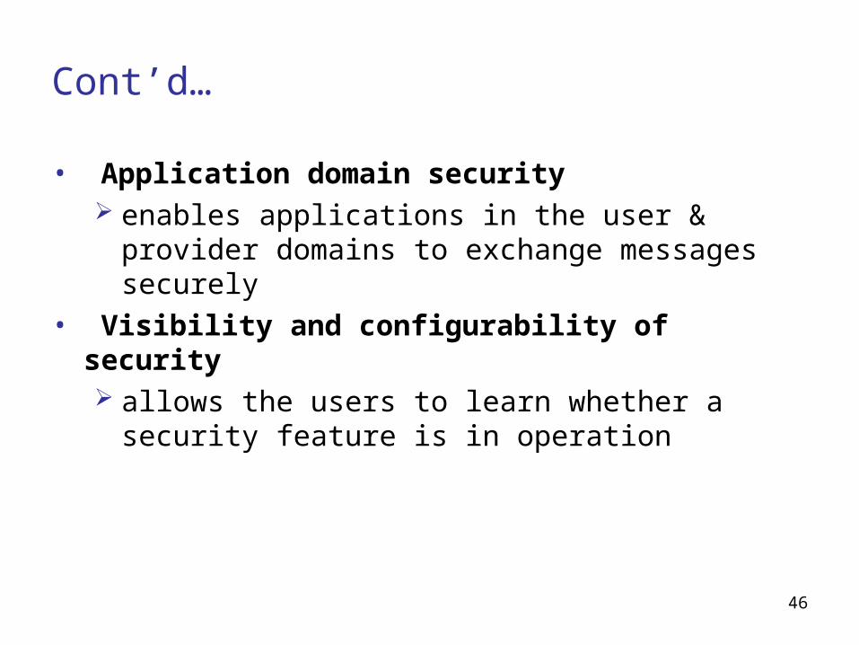
• Application domain security enables applications in the user & provider
domains to exchange messages securely• Visibility and configurability of security
allows the users to learn whether a security feature is in operation
47
LTE Future and Uses
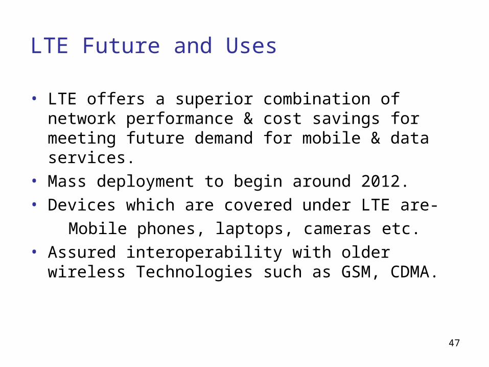
• LTE offers a superior combination of network performance & cost savings for meeting future demand for mobile & data services.
• Mass deployment to begin around 2012.• Devices which are covered under LTE are- Mobile phones, laptops, cameras etc.• Assured interoperability with older wireless
Technologies such as GSM, CDMA.