lte presentaion
TRANSCRIPT

High Academy for CommunicationCollaboration with Omdurman Islamic University
Presented by:
Swar Eldahb Taha Elbala
Supervisor:
Dr. Khalid Hamid Bilal
1
E2E Delay Performance Evaluation in
LTE-Network
2013
Objective:
to evaluate End-to-End Delay in LTE network environment by using (VoIP) traffic & take into account the affecting parameters
End-to-End Delay
3
What is LTE ?
In Nov. 2004, 3GPP began a project to define the long-term evolution (LTE) of Universal Mobile Telecommunications System (UMTS) cellular technology Higher performance Backwards compatible Wide application
4
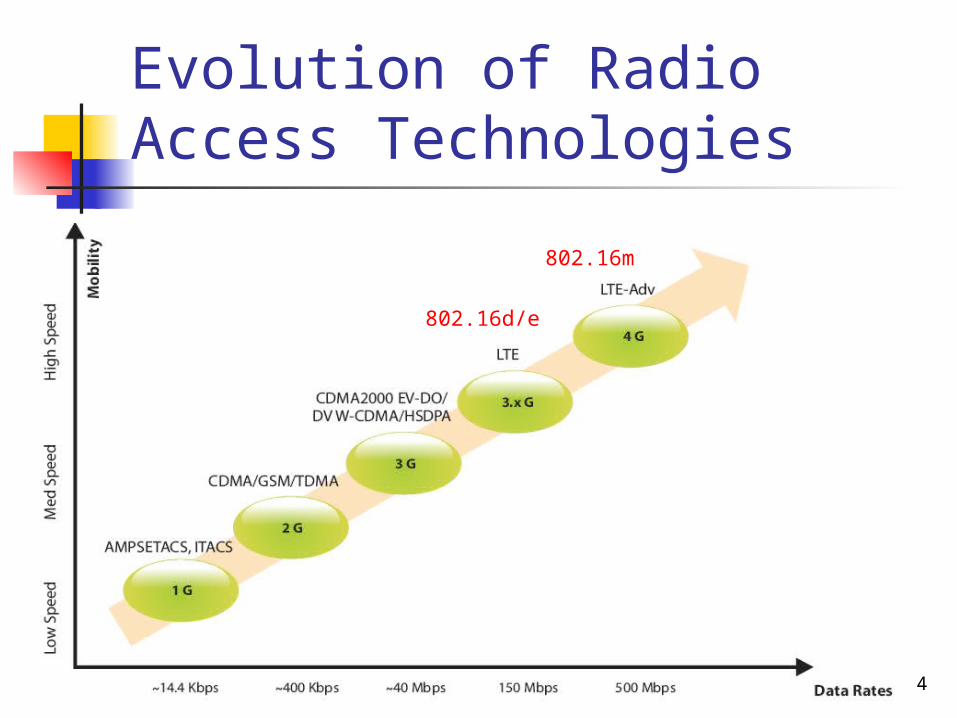
Evolution of Radio Access Technologies
802.16d/e
802.16m
5
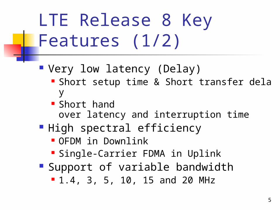
LTE Release 8 Key Features (1/2)
Very low latency (Delay) Short setup time & Short transfer delay Short hand over latency and interruption time
High spectral efficiency OFDM in Downlink Single‐Carrier FDMA in Uplink
Support of variable bandwidth 1.4, 3, 5, 10, 15 and 20 MHz
6
LTE Release 8 Key Features (2/2)
Compatibility and interworking with earlier 3GPP Releases
FDD and TDD within a single radio access technology
Efficient Multicast/Broadcast
7
LTE Basic Concepts
LTE employs Orthogonal Frequency Division Multiple Access (OFDMA) for downlink data transmission and Single Carrier FDMA (SC-FDMA) for uplink transmission
8
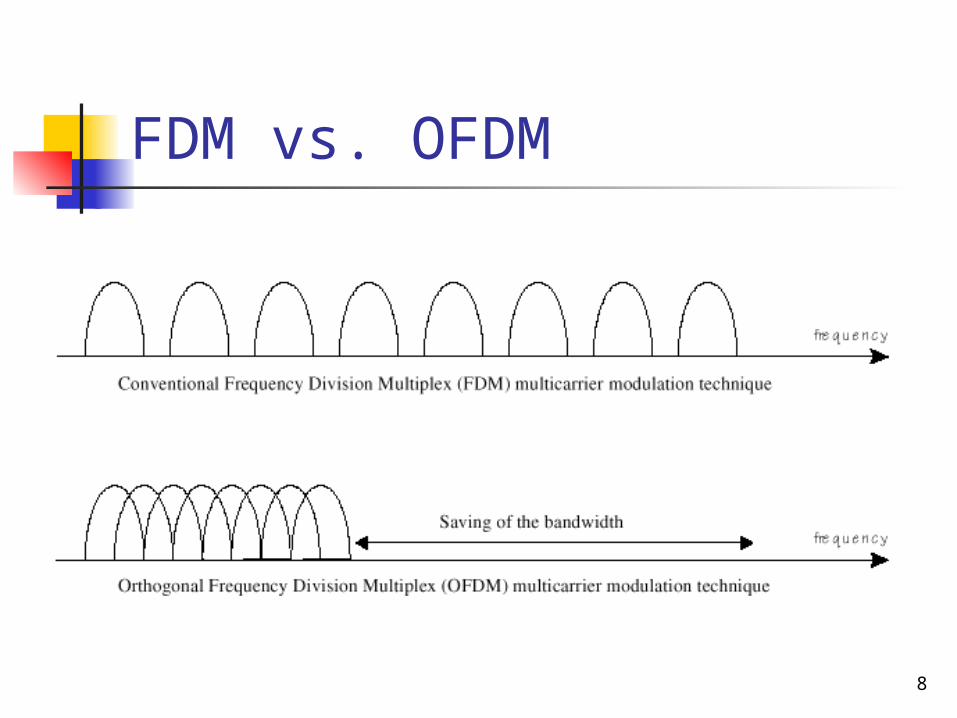
FDM vs. OFDM
9
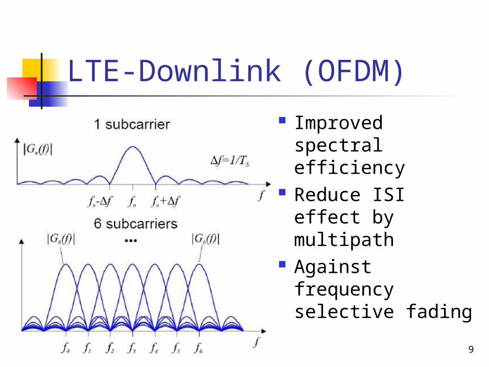
LTE-Downlink (OFDM)
Improved spectral efficiency
Reduce ISI effect by multipath
Against frequency selective fading
10
LTE Uplink (SC-FDMA) SC-FDMA is a new single carrier multiple access
technique which has similar structure and performance to OFDMA
11
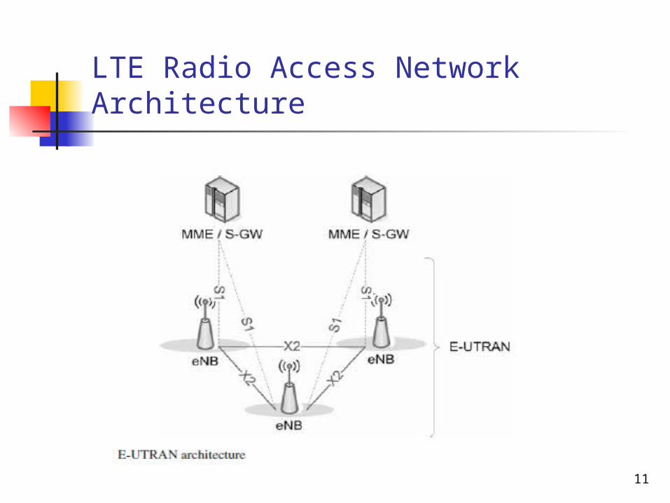
LTE Radio Access Network Architecture
12
Generic Frame Structure
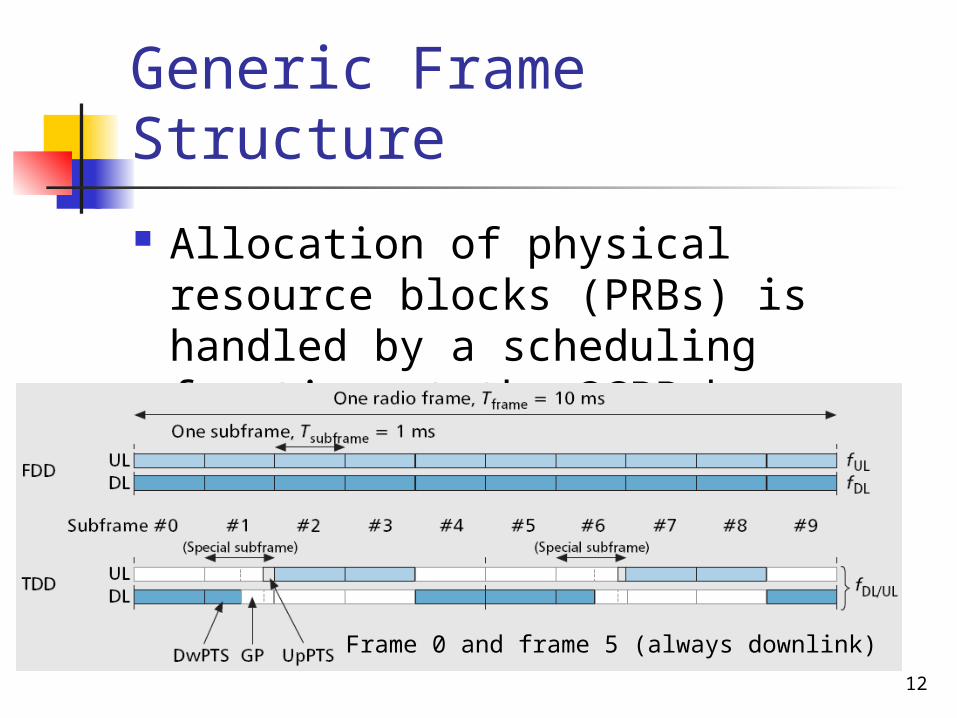
Allocation of physical resource blocks (PRBs) is handled by a scheduling function at the 3GPP base station (eNodeB)
Frame 0 and frame 5 (always downlink)
13
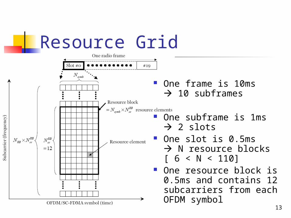
Resource Grid
One frame is 10ms 10 subframes
One subframe is 1ms 2 slots
One slot is 0.5ms N resource blocks[ 6 < N < 110]
One resource block is 0.5ms and contains 12 subcarriers from each OFDM symbol
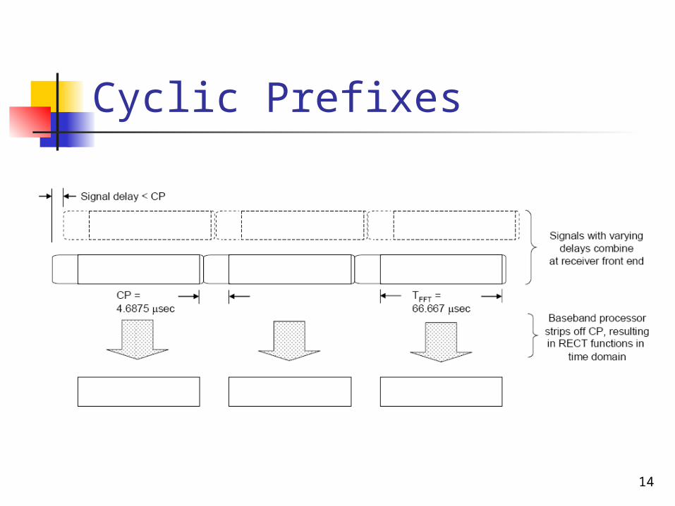
14
Cyclic Prefixes

15
Layered OFDMA
The bandwidth of basic frequency block is, 15–20 MHz
Layered OFDMA radio access scheme in LTE-A will have layered transmission bandwidth, support of layered environments and control signal formats
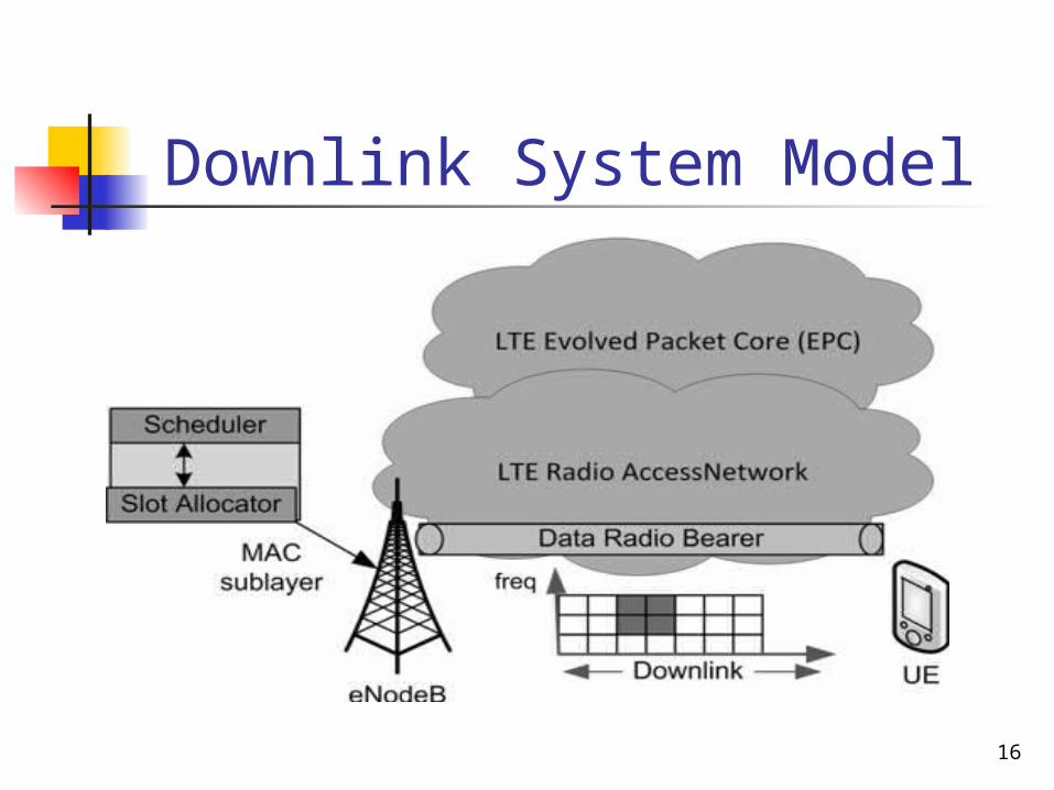
16
Downlink System Model
Opportunistic Packet Scheduling Algorithms
Suitable for non real traffic It take into account channel quality and the
past user throughput
Proportional Fairness (PF)
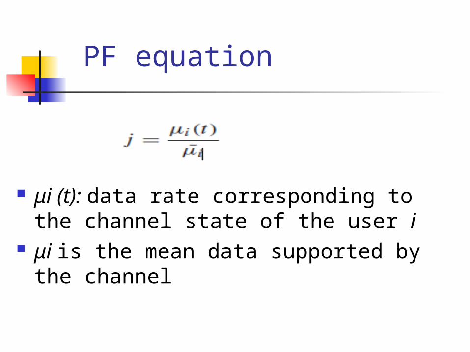
PF equation
μi (t): data rate corresponding to the channel state of the user i
μi is the mean data supported by the channel
Opportunistic Packet Scheduling Algorithms
designed to support multiple real-time data users in CDMA-HDR system
It supports multiple data users with different QoS requirements.
Maximum Largest Weighted Delay First (M-LWDF)
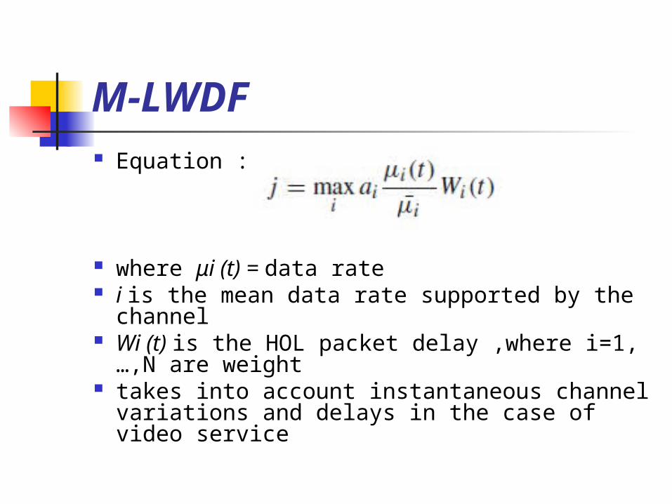
M-LWDF Equation :
where μi (t) = data rate i is the mean data rate supported by the channel Wi (t) is the HOL packet delay ,where i=1,…,N are
weight takes into account instantaneous channel variations
and delays in the case of video service
Exponential Proportional Fairness (EXP/PF)
This algorithm has been designed to increase the priority of real-time flows with respect to non-real-time ones
this means that an user can belong (RT) or (NRT) services.
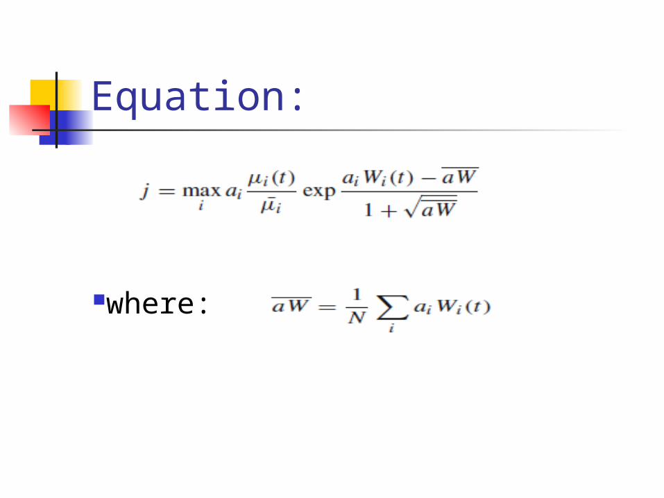
Equation:
where:
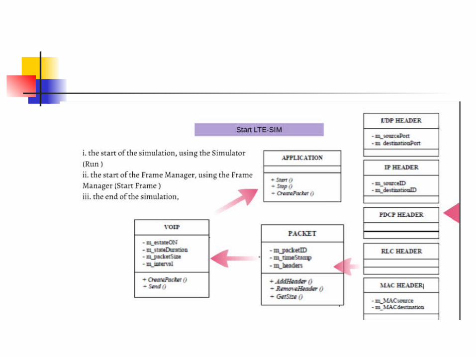
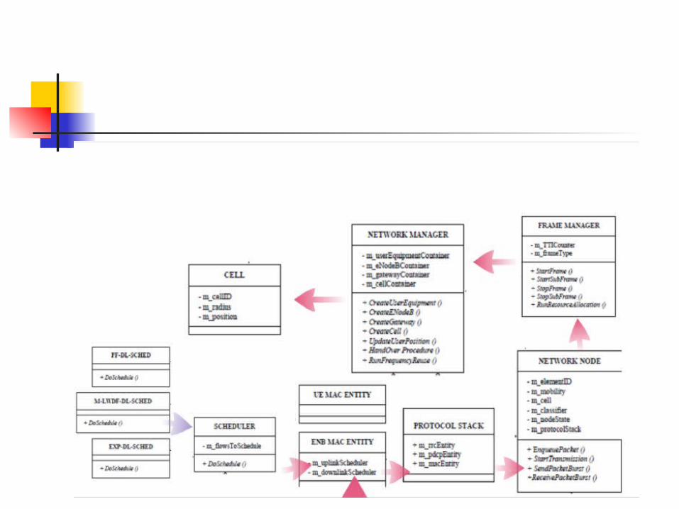
Simulation & Performance Evaluation
performance evaluation for LTE-SIM Simulation Environments output results
LTE-SIM
Open source software ,written c ++ & working Linux environments
LTE-Sim has been conceived to simulate uplink and downlink scheduling strategies in multi-cell/multi-users environments taking into account user mobility, radio resource optimization, frequency reuse techniques and other aspects
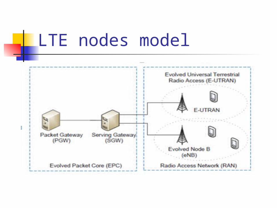
LTE nodes model
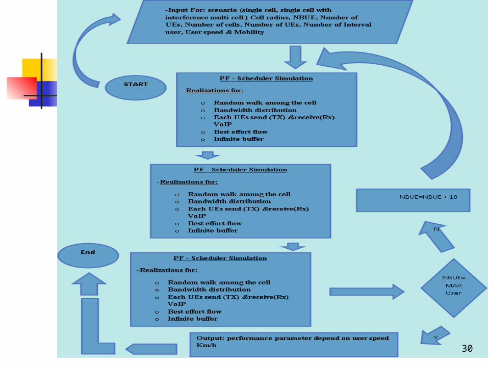
Simulation Design:
In the simulation design we will create three scenarios as follow:Scenario 1:Single cellScenario 2: Single cell with interference Scenario 3:Multiple cell
29
30

1 Scenario 1: Single cell
31
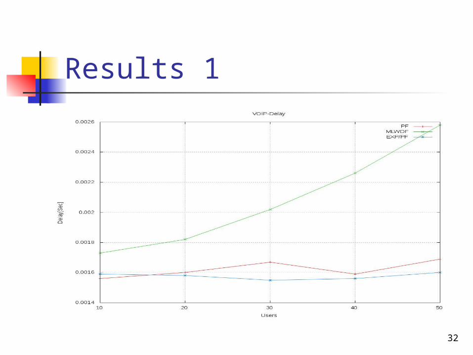
Results 1
32
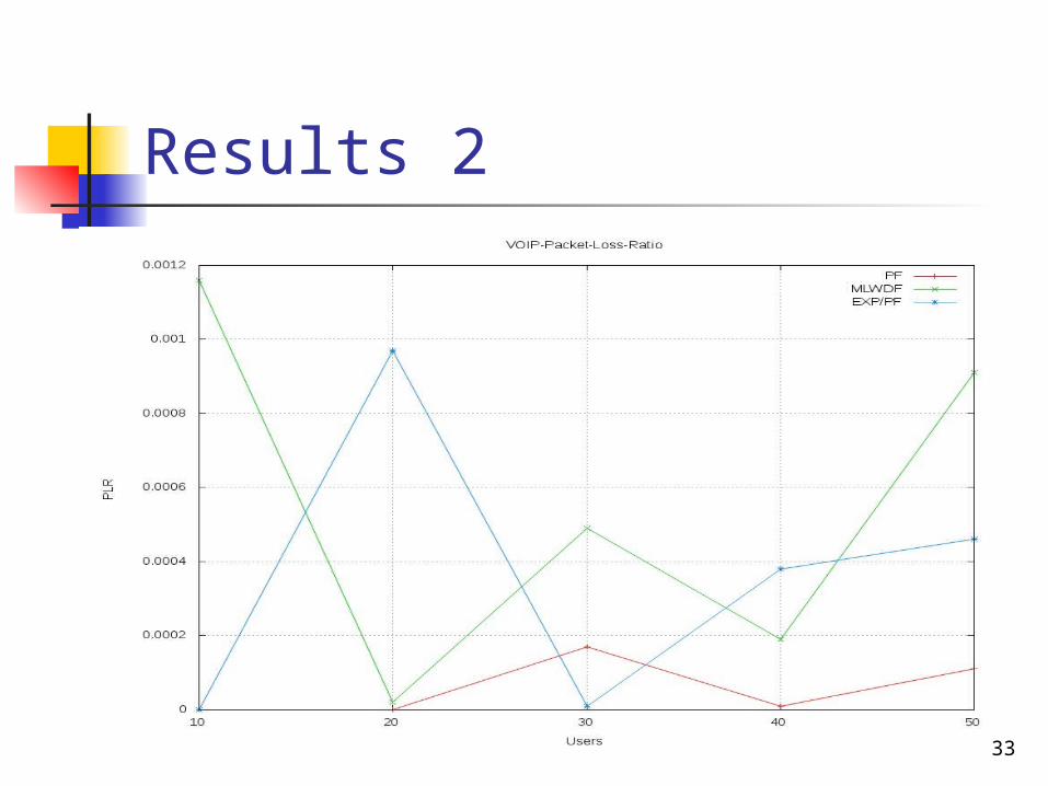
Results 2
33
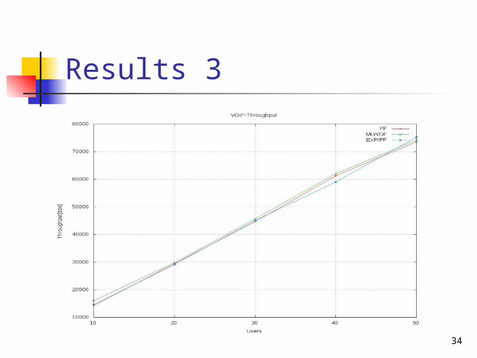
Results 3
34
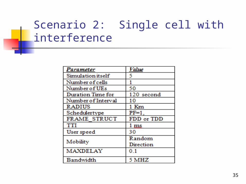
Scenario 2: Single cell with interference
35

Result 1
36
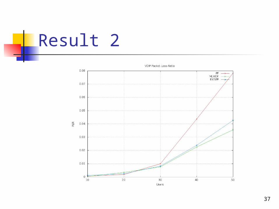
Result 2
37
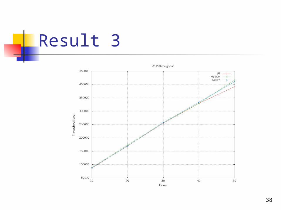
Result 3
38
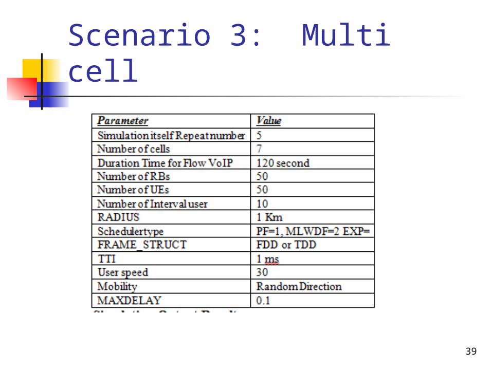
Scenario 3: Multi cell
39
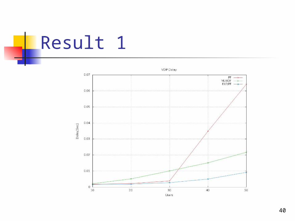
Result 1
40
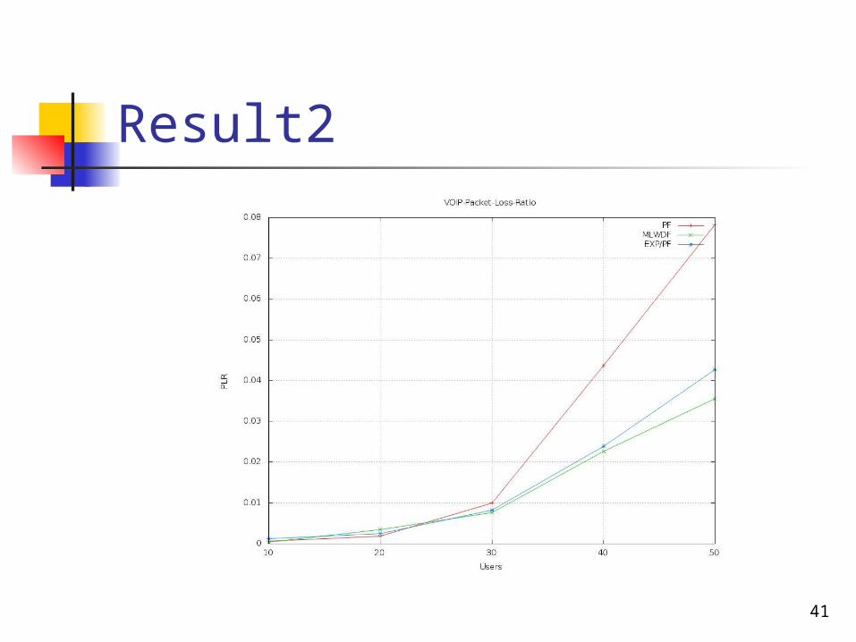
Result2
41
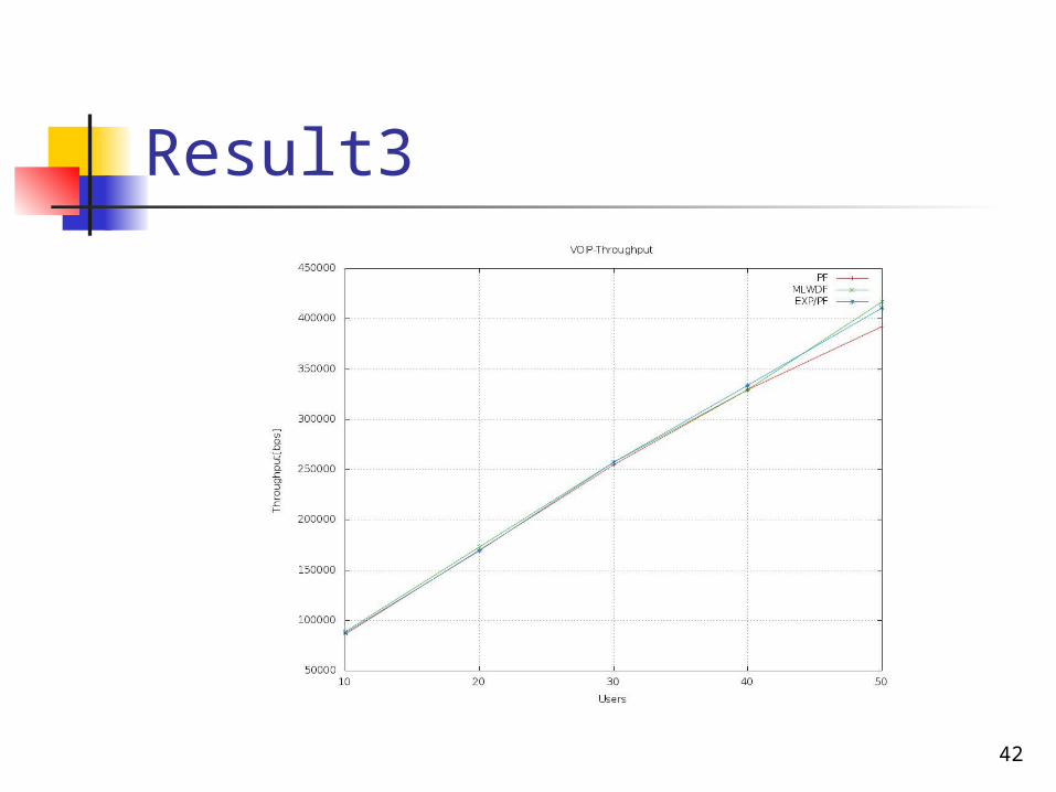
Result3
42
Conclusions As user increase the delay amount increase Maximum delay value 0.22 second in all scenarios (multi cell with
hand over enable ) Proportional fairness has highest delay amount EXP/PF give much acceptable delay & PLR in all scenarios
43
Recommendations
Experience the delay amount in different congested traffic model (video &FTP) in all scenarios and comparing them with VoIP result with same scheduling algorithm
Perform the simulation with different bandwidth (1.3 ,5&10 MHZ) Suggest new algorithm to minimize delay & PLR value in VoIP traffic
44
Thank you ,,
45