lto_scsi_2013.pdf
DESCRIPTION
manual de usuario ltoTRANSCRIPT

13 February 2013 GA32-0928-01
IBM® TotalStorage® LTO Ultrium Tape Drive
SCSI Reference
IBM LTO SCSI Reference 1

GA32-0928-01 13 February 2013
Second Edition (13 February 2013)
This edition applies to the IBM System Storage LTO Ultrium Tape Drive SCSI Reference and to all subsequent releases and modifications unless otherwise indicated in new editions.
Copyright International Business Machines Corporation 2011.
US Government Users Restricted Rights -- Use, duplication or disclosure restricted by GSA ADP Schedule Contract with IBM Corp.
Note
Before using this manual and the product it supports, read the information under Appendix B. Notices.
2 IBM LTO SCSI Reference

13 February 2013 GA32-0928-01
0. Read This First
This is the first edition of the IBM System Storage LTO Tape Drive SCSI Reference.
0.1 Summary of Changes
0.1.1 First Edition, April 2011
The IBM System Storage LTO Ultrium Tape Drive SCSI Reference describes the SCSI interface for the IBM LTO 1 tape drive through the IBM LTO 4 tape drive. This document is the first edition of the IBM System Storage LTO Tape Drive SCSI Reference which describes the SCSI interface for the IBM LTO 5 tape drive and does not describe the previous generation tape drives that are described in the IBM System Storage LTO Ultrium Tape Drive SCSI Reference.
The list of Functional Change Requests (FCR) applied to the previous generation device (i.e., LTO4) that are included follow:
FCR 3163r3 - IP Address Information Configuration;
FCR 3164 - LTO Engineering Log (Buffer ID 06h);
FCR 3165 - LTO5 - TapeAlert 10h behavior;
FCR 3167 - Persistent Reserve Out SCOPE field;
FCR 3173 - Device Attributes Mode Pages;
FCR 3174r2 - LTO5 - Sleep Mode (Mode Page 1Ah);
FCR 3175r3 - LTO5 - Partitioning SCSI changes;
FCR 3176r1 - Encryption Selection mode page;
FCR 3177 - LTO5 - SCSI Identifier updates;
FCR 3178r2 - LTO5 - SkipSync;
FCR 3179r2 - LTO5 - Append-only mode (data-safe);
FCR 3180r2 - LTO5 - Transport Log & Mode pages;
FCR 3181 - LTO5 Report Supported OpCode;
FCR 3183r1 - LTO5 Programmable Early Warning;
FCR 3184 - LTO5 Volume Statistics log page (17h);
FCR 3185 - LTO5 Device Statistics log page (14h);
FCR 3186 - LTO5 Data Compression log page (1Bh);
FCR 3187 - SPIN & SPOUT (OOBE-KMIP-SSC-4);
FCR 3188r1 - LTO5 Engineering & Speed log pages;
FCR 3189 - Extended Write-Read Diagnostics;
FCR 3192r1 - Tape map control mode page;
FCR 3193 - End of partition behavior control;
FCR 3194 - SAS TLR count in log pages;
FCR 3195 - LTO5 ITD;
FCR 3197 - Update standard inquiry version field;
FCR 3199 - LTO5 Engr Diags for Manufacturing;
FCR 3202 - CM from EOD dataset Read Buffer;
FCR 3205 - Drive Type in Inquiry C0h;
FCR 3208 - Logical block protection;
FCR 3211r1 - LUN1 licenses IBM general + OEM;
FCR 3212 - LOAD ID for LTO HH V2 drives;
IBM LTO SCSI Reference a

GA32-0928-01 13 February 2013
0.1.2 Second Edition, February 2013
This document is the second edition of the IBM System Storage LTO Tape Drive SCSI Reference which describes the SCSI interface for the IBM LTO 5 and LTO 6 tape drives.
The list of defects and changes applied to the first edition of the IBM System Storage LTO Tape Drive SCSI Reference to create this edition follow:
30908 - Space sequential filemarks is not supported on LTO. Needs removed. (see 5.2.35)
31159 - Correct broken link BLOCK DESCRIPTOR LENGTH in MODE SENSE (6/10) - 1Ah/5Ah (see 5.2.10 on page 91)
31491 - CRQST bit of VHF data has typo (see 6.4.9.2.1)
31641 - VCR MAM parameter is listed as 4 bytes but values shown are 2-b (see 6.5.2.2.5)
31642 - Add cross reference to LogSense page codes
31651 - FVT: PRO w/ exclusive access all regs fails 05 2400 (see 5.2.12)
31684 - LTO5LC - MP01h TB bit incorrect (see 6.6.5)
31718 - WTRE (WORM Tamper Read Enable) field in MP 10h (Device Configuration mode page) default value incorrect (see 6.6.11)
31804 - MP 1Ch issue - Error generated by Test Bit is incorrect (see 6.6.17)
31999 - LTO SCSI Ref: ASC/ASCQ EE31 description should be "Key Unknown" (see Annex B.)
32115 - Partition size fields in Medium Partition mode page should state values are rounded down (see 6.6.13)
32680 - Fix fonts, cross-references, and editing to transition to newer version of document publishing application. Prepare document for incorporation of LTO6 changes.
32701 - Partition mode page too many periods above partition size table
32722 - Clean-up the document for publishing and make conditional text and cross references consistent
32746 - FVT: HH5FC loadId of SAS_3573 0000
32747 - FVT: LTO5HHSAS with FC load id
32802 - CV:Mode page 19h RRTOV documentation incorrect
32860 - Inq page B1h missing from Inq page 00h
32862 IP 83h T10 vendor ID designator length incorrect. Should be 22h
32863 - IP 87h missing MP 0Ah[F0h] & 10h[01h]
32864 LP 37h needs updated for 4 partitions
32886 In the command table WRITE ATTRIBUTE should have 'N' under NRD
32914 Missing number in Size field of LP 38h table
32941 Native Transfer rate incorrect in Introduction and in Annex A
33053 Annex B doesn't list NO SENSE/IDLE_C CONDITION ACTIVATED BY TIMER
33137 LTO SCSI Ref: MKAD Key-Associated Data Descriptor
33212 Publication cleanup; fonts, XREF, etc., revision number
33219 Duplicate clause number and CDB confusion
f3178r5 - Update SkipSync for LTO6 (see 6.6.21.5.1)
f3182r2 - Dynamic Runtime Information clean-up (see 5.2.18), (see 5.2.42), and (see 6.1)
f3206 - Units of measure for data storage
f3227 - Make OIR saveable (see 6.6.11)
f3229 - Deferred Check Condition (DCC) affinity(see 4.16.3)
f3233 - LTO6 SCSI Identifier updates
f3233r1 - LTO6 SCSI Identifier updates - corrections
f3233r2 - LTO6 SCSI Identifier Updates - Fix Set Capacity
f3235 - Manufacture assigned serial number VPD page (B1h) (see 6.3.10)
b IBM LTO SCSI Reference

13 February 2013 GA32-0928-01
f3237 - Read Block Limits MLOI (see 5.2.16.2)
f3237r1 Maximum Logical Object Identifier and EW
f3240 - LP17 Remaining Native Capacity (see 6.4.12)
f3241 - BOP Caching (see 4.3.2)
f3242 - LTO6 Encryption Algorithm (see 6.8.2.3)
f3244 - Add create FMR tape and update drive From FMR tape (see 6.2.2)
f3246 - OEM Specific Inquiry field
f3248 - LTO6 Timeout values and the REPORT SUPPORTED OPERATION CODES command (see 5.2.24.3)
f3249 Ignore PS bit on MODE SELECT
f3250 LOCATE to EOD
f3251 - Encryption Sense Key changes (see Annex B.)
f3253 Partition mode page partition size table mods
f3254 Crypto hash and certificate updates
f3256 Standardized dump
f3257 Update LP31h for 4 partitions
f3258 Tape Diagnostic Data - correct PARAMETER CODE field
IBM LTO SCSI Reference c

GA32-0928-01 13 February 2013
d IBM LTO SCSI Reference

13 February 2013 GA32-0928-01
ContentsPage
0. Read This First .................................................................................................................................................. a0.1 Summary of Changes ................................................................................................................................... a
0.1.1 First Edition, April 2011 ........................................................................................................................... a0.1.2 Second Edition, February 2013 .............................................................................................................. b
1. Preface .............................................................................................................................................................. 11.1 Organization ................................................................................................................................................. 11.2 Related Publications ..................................................................................................................................... 1
2. Definitions, symbols, abbreviations, and conventions ...................................................................................... 32.1 Definitions ..................................................................................................................................................... 32.2 Conventions ............................................................................................................................................... 16
2.2.1 Bit Numbering ....................................................................................................................................... 162.2.2 Units of measure for data storage ......................................................................................................... 162.2.3 Subpages .............................................................................................................................................. 182.2.4 Text Markers ......................................................................................................................................... 182.2.5 Hyperlinks ............................................................................................................................................. 18
2.3 Tape Drive Model Names ........................................................................................................................... 19
3. Introduction ..................................................................................................................................................... 213.1 Drive Overview ........................................................................................................................................... 213.2 Supported Servers and Operating Systems ............................................................................................... 22
3.2.1 Primary Interface Attachment ............................................................................................................... 223.3 Supported Device Drivers .......................................................................................................................... 233.4 Supported Tape Cartridges ........................................................................................................................ 233.5 Microcode Detection of Errors .................................................................................................................... 24
3.5.1 Fencing Behavior .................................................................................................................................. 24
4. Implementation Considerations ...................................................................................................................... 254.1 Write modes ............................................................................................................................................... 25
4.1.1 Write mode introduction ........................................................................................................................ 254.1.2 Overwrite-allowed mode ....................................................................................................................... 254.1.3 Append-only mode (also known as Data-safe mode) ........................................................................... 25
4.2 Volume partitioning ..................................................................................................................................... 284.2.1 Volume partitioning overview ................................................................................................................ 284.2.2 Wrap-wise Partitioning .......................................................................................................................... 284.2.3 Partitioning and capacity scaling ........................................................................................................... 314.2.4 Partitioning and media types ................................................................................................................ 324.2.5 Partitioning and reformatting ................................................................................................................. 324.2.6 Partitioning and encryption ................................................................................................................... 32
4.3 Object buffer ............................................................................................................................................... 334.3.1 Object buffer introduction ...................................................................................................................... 334.3.2 BOP caching ......................................................................................................................................... 33
4.3.2.1 BOP caching side effects ................................................................................................................ 334.4 Programmable early warning ..................................................................................................................... 344.5 Logical block protection .............................................................................................................................. 35
4.5.1 Logical block protection overview ......................................................................................................... 354.5.1.1 Logical block protection ................................................................................................................... 35
4.5.2 Protection information on a volume ...................................................................................................... 354.5.3 Logical blocks and protection information ............................................................................................. 364.5.4 .Protecting logical blocks transferred during writes .............................................................................. 374.5.5 Protecting logical blocks transferred during reads ................................................................................ 384.5.6 File verification of protection information .............................................................................................. 384.5.7 Verification to EOD of protection information ........................................................................................ 39
IBM LTO SCSI Reference i

GA32-0928-01 13 February 2013
4.6 Multiple Port Behavior ................................................................................................................................ 404.7 Data Transfer, Block Limits, and Fixed Block Option ................................................................................. 414.8 Request Sense Information, ILI, and Command Interactions ..................................................................... 42
4.8.1 General Read-Type Handling ............................................................................................................... 424.8.2 Interactions Summary ........................................................................................................................... 43
4.9 Cleaning the Drive in a Library ................................................................................................................... 464.10 Drive Cleaning Indicators ......................................................................................................................... 47
4.10.1 Panel Cleaning Indication ................................................................................................................... 474.10.2 Host Interface - Dynamic Cleaning Indicators ..................................................................................... 474.10.3 Host Interface - Static Cleaning Indicator (Sense Data Byte 70) ........................................................ 47
4.11 WORM Behaviors ..................................................................................................................................... 484.11.1 Conditions for Writing .......................................................................................................................... 484.11.2 Command Behavior When WORM Medium Has Been Tampered With ............................................. 48
4.12 Device Hardware Encryption .................................................................................................................... 494.12.1 Encryption Control - IBM Proprietary Protocol (IPP) ........................................................................... 494.12.2 Encryption Control - T10 Standards .................................................................................................... 49
4.13 Attachment Features ................................................................................................................................ 504.13.1 Types of Interface Attachments .......................................................................................................... 504.13.2 Common Tape LUN Behaviors ........................................................................................................... 50
4.13.2.1 Power-On ...................................................................................................................................... 504.13.2.2 Reset Strategy .............................................................................................................................. 504.13.2.3 Abort Handling .............................................................................................................................. 504.13.2.4 Multi-initiator Support .................................................................................................................... 524.13.2.5 Status Codes ................................................................................................................................. 53
4.13.3 Features of the Fibre Channel Interface ............................................................................................. 534.13.3.1 Topology ....................................................................................................................................... 53
4.13.3.1.1 Two-Node Switched Fabric Topology ...................................................................................... 544.13.3.1.2 Two-Node Direct Connection Topology ................................................................................... 54
4.13.3.2 Speed ............................................................................................................................................ 544.13.3.3 Addressing Assignments ............................................................................................................... 55
4.13.4 Features of the Serial Attached SCSI (SAS) Interface ....................................................................... 554.14 Device Clocks ........................................................................................................................................... 564.15 Dynamic runtime information .................................................................................................................... 57
4.15.1 Dynamic runtime information overview ............................................................................................... 574.15.2 Dynamic runtime information timestamp ............................................................................................. 584.15.3 Setting dynamic runtime information into the drive ............................................................................. 584.15.4 Retrieving dynamic runtime information from the drive ....................................................................... 584.15.5 Management of dynamic runtime information ..................................................................................... 58
4.15.5.1 Dynamic Runtime Information Lifetime ......................................................................................... 594.16 Error Information ...................................................................................................................................... 60
4.16.1 Sense Data ......................................................................................................................................... 604.16.2 Sense Data Management ................................................................................................................... 604.16.3 Deferred Check Condition (DCC) ....................................................................................................... 604.16.4 Unit Attention Conditions .................................................................................................................... 604.16.5 Persistent Errors ................................................................................................................................. 61
4.16.5.1 Fencing Behavior .......................................................................................................................... 614.16.5.1.1 ALLOW_NO_OPERATION ...................................................................................................... 614.16.5.1.2 ALLOW_LOCATE .................................................................................................................... 614.16.5.1.3 ALLOW_UNLOAD ................................................................................................................... 624.16.5.1.4 MID-TAPE RECOVERY .......................................................................................................... 62
4.16.5.1.4.1 Normal operation (i.e., MTR Fence) ................................................................................... 624.16.5.1.4.2 Panic Fence operation ....................................................................................................... 62
4.17 Medium auxiliary memory ......................................................................................................................... 644.18 Volume Coherency ................................................................................................................................... 654.19 Diagnostics ............................................................................................................................................... 66
4.19.1 Extended Write/Read Test diagnostic ................................................................................................. 664.20 Error history (i.e., drive dump) .................................................................................................................. 67
ii IBM LTO SCSI Reference

13 February 2013 GA32-0928-01
4.20.1 Error history overview ......................................................................................................................... 674.20.2 Retrieving error history with the READ BUFFER command ............................................................... 67
5. SCSI Commands ............................................................................................................................................ 695.1 SCSI Commands Overview ........................................................................................................................ 69
5.1.1 Unsupported SCSI Commands ............................................................................................................. 695.1.2 Supported SCSI Commands ................................................................................................................. 69
5.1.2.1 Supported SCSI Commands on LUN 1 ........................................................................................... 695.1.2.2 Supported SCSI Commands on LUN 0 ........................................................................................... 695.1.2.3 Control Byte Definition ..................................................................................................................... 72
5.2 SCSI Commands Listing ............................................................................................................................ 735.2.1 ALLOW OVERWRITE - (82h) ............................................................................................................... 735.2.2 ERASE - 19h ........................................................................................................................................ 745.2.3 FORMAT MEDIUM - 04h ...................................................................................................................... 755.2.4 INQUIRY - 12h ...................................................................................................................................... 77
5.2.4.1 Standard Inquiry Data ..................................................................................................................... 775.2.5 LOAD/UNLOAD - 1Bh ........................................................................................................................... 835.2.6 LOCATE(10/16) - 2Bh/92h ................................................................................................................... 855.2.7 LOG SELECT - 4Ch ............................................................................................................................. 875.2.8 LOG SENSE - 4Dh ............................................................................................................................... 885.2.9 MODE SELECT (6/10) - 15h/55h .......................................................................................................... 895.2.10 MODE SENSE (6/10) - 1Ah/5Ah ......................................................................................................... 915.2.11 PERSISTENT RESERVE IN (PRIN)- 5Eh .......................................................................................... 93
5.2.11.1 READ KEYS service action ........................................................................................................... 935.2.11.2 READ RESERVATION service action ........................................................................................... 945.2.11.3 REPORT CAPABILITIES service action ....................................................................................... 955.2.11.4 READ FULL STATUS service action ............................................................................................ 97
5.2.11.4.1 Full status descriptors .............................................................................................................. 985.2.12 PERSISTENT RESERVE OUT - 5Fh ................................................................................................. 99
5.2.12.1 Basic PERSISTENT RESERVE OUT parameter list .................................................................. 1005.2.12.2 PERSISTENT RESERVE OUT command with REGISTER AND MOVE service action parameters
1015.2.13 PREVENT ALLOW MEDIUM REMOVAL - 1Eh ................................................................................ 102
5.2.13.1 Medium removal .......................................................................................................................... 1025.2.14 READ - 08h ....................................................................................................................................... 1035.2.15 READ ATTRIBUTE - 8Ch ................................................................................................................. 104
5.2.15.1 ATTRIBUTE VALUES service action .......................................................................................... 1055.2.15.2 ATTRIBUTE LIST service action ................................................................................................. 1055.2.15.3 LOGICAL VOLUME LIST service action ..................................................................................... 1065.2.15.4 PARTITION LIST service action .................................................................................................. 1065.2.15.5 SUPPORTED ATTRIBUTES service action ................................................................................ 107
5.2.16 READ BLOCK LIMITS - 05h ............................................................................................................. 1085.2.16.1 READ BLOCK LIMITS block length data .................................................................................... 1085.2.16.2 READ BLOCK LIMITS maximum logical object identifier data .................................................... 109
5.2.17 READ BUFFER - 3Ch ....................................................................................................................... 1105.2.17.1 MODE[00h] – Combined header and data .................................................................................... 1115.2.17.2 MODE[02h] – Data ........................................................................................................................ 1115.2.17.3 MODE[03h] – Descriptor ............................................................................................................... 1115.2.17.4 MODE[07h] – Descriptor with algorithmic offset boundary ............................................................ 1125.2.17.5 MODE[0Ah] – Read data from echo buffer ................................................................................... 1125.2.17.6 MODE[0Bh] – Echo buffer descriptor ............................................................................................ 1135.2.17.7 MODE[1Ch] – Error history ........................................................................................................... 113
5.2.17.7.1 Error history overview ............................................................................................................ 1135.2.17.7.2 MODE[1Ch] 00h to 03h: Error history directory ....................................................................... 115
5.2.17.7.2.1 Error history directory entry .............................................................................................. 1165.2.17.7.3 MODE[1Ch] 10h to FEh: Error history data buffer ................................................................... 117
5.2.17.7.3.1 MODE[1Ch] 10h: Current error history snapshot ............................................................... 117
IBM LTO SCSI Reference iii
GA32-0928-01 13 February 2013
5.2.17.7.3.2 MODE[1Ch] 20h: Emergency dump ................................................................................... 1175.2.17.7.3.3 MODE[1Ch] 21h to 28h: Prioritized flash dump ................................................................. 1175.2.17.7.3.4 MODE[1Ch] EFh: Error history names list .......................................................................... 118
5.2.17.7.3.4.1 Error history names entry ............................................................................................ 1185.2.17.7.4 MODE[1Ch] FEh: Clear error history I_T_L nexus .................................................................. 1195.2.17.7.5 MODE[1Ch] FFh: Clear error history I_T_L nexus and release snapshot ............................... 119
5.2.18 READ DYNAMIC RUNTIME ATTRIBUTE - D1h .............................................................................. 1205.2.18.1 READ DYNAMIC RUNTIME ATTRIBUTE Service Action .......................................................... 1215.2.18.2 SUPPORTED ATTRIBUTES service action ................................................................................ 1215.2.18.3 ATTRIBUTE VALUES FOR THIS I_T NEXUS service action ..................................................... 1225.2.18.4 ATTRIBUTE VALUES FOR ALL I_T NEXUSES service action .................................................. 123
5.2.19 READ POSITION - 34h ..................................................................................................................... 1255.2.19.1 READ POSITION command description ..................................................................................... 1255.2.19.2 READ POSITION data format, short form ................................................................................... 1255.2.19.3 READ POSITION data format, long form .................................................................................... 1285.2.19.4 READ POSITION data format, extended form ............................................................................ 129
5.2.20 RECEIVE DIAGNOSTIC RESULTS - 1Ch ....................................................................................... 1325.2.21 RELEASE UNIT - 17h/57h ................................................................................................................ 1335.2.22 REPORT DENSITY SUPPORT - 44h ............................................................................................... 134
5.2.22.1 Report Density Support data format ............................................................................................ 1345.2.22.1.1 Density descriptor overview ................................................................................................... 1345.2.22.1.2 Density information ................................................................................................................ 136
5.2.23 REPORT LUNS - A0h ....................................................................................................................... 1375.2.23.1 Report LUNs data format ............................................................................................................ 137
5.2.24 REPORT SUPPORTED OPERATION CODES - A3h[0Ch] ............................................................. 1395.2.24.1 All_commands parameter data format ........................................................................................ 1405.2.24.2 One_command parameter data format ....................................................................................... 1425.2.24.3 Command timeouts descriptor .................................................................................................... 143
5.2.24.3.1 Overview ................................................................................................................................ 1435.2.24.3.2 WRITE BUFFER command timeouts descriptor command specific field usage ................... 147
5.2.25 REPORT SUPPORTED TASK MANAGEMENT FUNCTIONS - A3h[0Dh] ...................................... 1485.2.25.1 REPORT SUPPORTED TASK MANAGEMENT FUNCTIONS parameter data ......................... 148
5.2.26 REPORT TIMESTAMP - A3h[0Fh] ................................................................................................... 1505.2.26.1 REPORT TIMESTAMP parameter data ...................................................................................... 150
5.2.27 REQUEST SENSE - 03h .................................................................................................................. 1525.2.27.1 Sense Data Format ..................................................................................................................... 153
5.2.28 RESERVE - 16h/56h ........................................................................................................................ 1595.2.29 REWIND - 01h .................................................................................................................................. 1605.2.30 SECURITY PROTOCOL IN (SPIN) - A2h ......................................................................................... 1615.2.31 SECURITY PROTOCOL OUT (SPOUT) - B5h ................................................................................. 1625.2.32 SEND DIAGNOSTIC - 1Dh ............................................................................................................... 1635.2.33 SET CAPACITY - 0Bh ...................................................................................................................... 1655.2.34 SET TIMESTAMP - A4h[0Fh] ........................................................................................................... 167
5.2.34.1 SET TIMESTAMP Parameter List ............................................................................................... 1675.2.35 SPACE (6/16) - 11h/91h ................................................................................................................... 1695.2.36 TEST UNIT READY - 00h ................................................................................................................. 1715.2.37 VERIFY(6) - 13h ............................................................................................................................... 1725.2.38 WRITE - 0Ah ..................................................................................................................................... 1745.2.39 WRITE ATTRIBUTE - 8Dh ................................................................................................................ 1755.2.41 WRITE BUFFER - 3Bh ..................................................................................................................... 178
5.2.41.1 MODE[00h] – Combined header and data .................................................................................... 1785.2.41.2 MODE[02h] – Data ........................................................................................................................ 1795.2.41.3 MODE[04h] – Download microcode and activate .......................................................................... 1795.2.41.4 MODE[05h] – Download microcode, save, and activate ............................................................... 1795.2.41.5 MODE[06h] – Download microcode with offsets and activate ....................................................... 1795.2.41.6 MODE[07h] – Download microcode with offsets, save, and activate ............................................ 1805.2.41.7 MODE[0Ah] – Write data to echo buffer ........................................................................................ 180
iv IBM LTO SCSI Reference

13 February 2013 GA32-0928-01
5.2.42 WRITE DYNAMIC RUNTIME ATTRIBUTE - D2h ............................................................................. 1815.2.42.1 WRITE DYNAMIC RUNTIME ATTRIBUTE parameter list .......................................................... 181
5.2.43 WRITE FILEMARKS - 10h ................................................................................................................ 183
6. Parameters for SCSI Commands ................................................................................................................. 1856.1 Dynamic runtime attributes (DRA) ............................................................................................................ 187
6.1.1 Attribute format ................................................................................................................................... 1876.1.2 Attribute identifier values .................................................................................................................... 188
6.1.2.1 Attribute identifier values overview ................................................................................................ 1886.1.2.2 Logical unit type attributes ............................................................................................................. 188
6.1.2.2.1 I_T_L nexus identifying information descriptor ........................................................................ 1896.1.2.3 Target type attributes .................................................................................................................... 1926.1.2.4 Initiator type attributes ................................................................................................................... 193
6.2 Diagnostic Parameters (Diag) .................................................................................................................. 1956.2.1 Diag Page Formats ............................................................................................................................. 195
6.2.1.1 Page 00h ....................................................................................................................................... 1956.2.1.2 SendDiag Data - Page 00h ........................................................................................................... 1956.2.1.3 RcvDiag Data - Page 00h .............................................................................................................. 1956.2.1.4 Page 80h ....................................................................................................................................... 195
6.2.1.4.1 SendDiag - Page 80h .............................................................................................................. 1956.2.1.5 RcvDiag - Page 80h ...................................................................................................................... 196
6.2.1.5.1 SIM/MIM Definition .................................................................................................................. 1966.2.1.5.1.1 SIM/MIM Header Data ....................................................................................................... 1976.2.1.5.1.2 SIM Messages ................................................................................................................... 198
6.2.2 Supported Page 80h Diags ................................................................................................................. 2036.2.3 Diag - SelfTest: Self Test .................................................................................................................... 204
6.2.3.1 SendDiag Command - Self Test .................................................................................................... 2046.2.3.2 RcvDiag Data - Self Test ............................................................................................................... 204
6.2.4 Diag - 0090h: Primary port wrap test .................................................................................................. 2056.2.4.1 SendDiag Parm Data - Primary port wrap test .............................................................................. 2056.2.4.2 RcvDiag Data - Primary port wrap test .......................................................................................... 205
6.2.5 Diag - 0100h: POST A ........................................................................................................................ 2066.2.5.1 SendDiag Parm Data - POST A .................................................................................................... 2066.2.5.2 RcvDiag Data - POST A ................................................................................................................ 207
6.2.6 Diag - 0101h: POST B Performance ................................................................................................... 2086.2.6.1 SendDiag Parm Data - POST B Performance .............................................................................. 2086.2.6.2 RcvDiag Data - POST B Performance .......................................................................................... 209
6.2.7 Diag - 0102h: POST C Media Test ..................................................................................................... 2106.2.7.1 SendDiag Parm Data - POST C Media Test ................................................................................. 2106.2.7.2 RcvDiag Data - POST C Media Test ............................................................................................. 210
6.2.8 Diag - 0103h: POST D Head Test ...................................................................................................... 2116.2.8.1 SendDiag Parm Data - POST D Head Test .................................................................................. 2116.2.8.2 RcvDiag Data - POST D Head Test .............................................................................................. 211
6.2.9 Diag - 0110h: Extended Write / Read Test ......................................................................................... 2126.2.9.1 Send Data – Extended Write / Read Test ..................................................................................... 2136.2.9.2 Results Data – Extended Write / Read Test .................................................................................. 217
6.2.10 Diag - 0160h: Force Dump ................................................................................................................ 2186.2.10.1 SendDiag Parm Data - Force Dump ........................................................................................... 2186.2.10.2 RcvDiag Data - Force Dump ....................................................................................................... 218
6.2.11 Diag -0161h: Write Dump to Cartridge .............................................................................................. 2196.2.11.1 SendDiag Parm Data - Write Dump to Cartridge ........................................................................ 2196.2.11.2 RcvDiag Data - Write Dump to Cartridge .................................................................................... 220
6.2.12 Diag - 0170h: Create FMR Cartridge (not on LTO5) ......................................................................... 2216.2.12.1 SendDiag Parm Data - Create FMR Cartridge ............................................................................ 2216.2.12.2 RcvDiag Results Data - Create FMR Cartridge ........................................................................... 222
6.2.13 Diag - 0171h: Unmake FMR Cartridge (not on LTO5) ...................................................................... 2236.2.13.1 SendDiag Parm Data - Unmake FMR Cartridge ......................................................................... 223
IBM LTO SCSI Reference v

GA32-0928-01 13 February 2013
6.2.13.2 RcvDiag Results Data - Unmake FMR Cartridge ........................................................................ 2246.2.14 Diag - 0175h: Use FMR Cartridge (not on LTO5) ............................................................................. 225
6.2.14.1 SendDiag Parm Data - Use FMR Cartridge ................................................................................ 2256.2.14.2 RcvDiag Results Data - Use FMR Cartridge ............................................................................... 226
6.2.15 Diag - 0190h: Set Traps .................................................................................................................... 2276.2.15.1 SendDiag Parm Data - Set Traps ................................................................................................ 2276.2.15.2 RcvDiag Data - Set Traps ........................................................................................................... 227
6.2.16 Diag - 0191h: Remove Traps ............................................................................................................ 2286.2.16.1 SendDiag Parm Data - Remove Traps ........................................................................................ 2286.2.16.2 RcvDiag Data - Remove Traps ................................................................................................... 229
6.2.17 Diag - 0210h: Terminate Immediate Command ................................................................................ 2306.2.17.1 Send Data – Terminate Immed Command .................................................................................. 2306.2.17.2 Results Data – Terminate Immed Command .............................................................................. 231
6.2.18 Diag - 1002h: Read Thermal Sensor ................................................................................................ 2326.2.18.1 SendDiag Parm Data - Read Thermal Sensor ............................................................................ 2326.2.18.2 RcvDiag Data - Read Thermal Sensor ........................................................................................ 233
6.2.19 Diag - 2002h: Reset Drive ................................................................................................................. 2346.2.19.1 SendDiag Parm Data - Reset Drive ............................................................................................ 2346.2.19.2 RcvDiag Command - Reset Drive ............................................................................................... 234
6.2.20 Cryptographic Diagnostics ................................................................................................................ 2356.3 Inquiry Vital Product Data Parameters (IP) .............................................................................................. 241
6.3.1 IP 00h: Supported Vital Product Data Pages ...................................................................................... 2416.3.1.1 Returned Data - Inquiry Page 00h: Supported Inquiry Pages ....................................................... 241
6.3.2 IP 03h: Firmware Designation ............................................................................................................. 2436.3.2.1 Returned Data - IP 03h: Firmware Designation ............................................................................ 243
6.3.3 IP 80h: Unit Serial Number ................................................................................................................. 2456.3.3.1 Returned Data - IP 80h: Unit Serial Number ................................................................................. 245
6.3.4 IP 83h: Device Identification ............................................................................................................... 2466.3.4.1 Returned Data - Inquiry Page 83h: Device Identification .............................................................. 246
6.3.4.1.1 T10 vendor ID designation descriptor ...................................................................................... 2476.3.4.1.2 Logical Unit (NAA) - WWNN designation descriptor ................................................................ 2486.3.4.1.3 Relative target port identifier designation descriptor ................................................................ 2496.3.4.1.4 Port Name (NAA) - WWPN designation descriptor .................................................................. 2506.3.4.1.5 Target Device Name (NAA) designation descriptor (SAS only) ............................................... 250
6.3.5 IP 86h: Extended INQUIRY Data ........................................................................................................ 2526.3.6 IP 87h: Mode Page Policy .................................................................................................................. 255
6.3.6.1 Returned Data - IP 87h: Mode Page Policy .................................................................................. 2556.3.7 IP 88h: SCSI ports .............................................................................................................................. 258
6.3.7.1 Returned Data - IP 88h: SCSI ports .............................................................................................. 2586.3.8 IP 90h: Protocol-Specific Logical Unit Information .............................................................................. 260
6.3.8.1 Returned Data - IP 88h: SCSI ports .............................................................................................. 2606.3.8.2 Logical unit information descriptor ................................................................................................. 261
6.3.9 IP B0h - Sequential-Access device capabilities .................................................................................. 2626.3.9.1 Returned Data - IP B0h: Sequential-Access device capabilities ................................................... 262
6.3.10 IP B1h - Manufacturer-assigned Serial Number ............................................................................... 2636.3.10.1 Returned Data - IP B1h: Manufacturer-assigned Serial Number ................................................ 263
6.3.11 IP C0h: Drive Component Revision Levels ....................................................................................... 2646.3.11.1 Returned Data - IP C0h: Drive Component Revision Levels ....................................................... 264
6.3.12 IP C1h: Drive Serial Numbers ........................................................................................................... 2666.3.12.1 Returned Data - IP C1h: Drive Serial Numbers ........................................................................... 266
6.3.13 IP C7h: Device Unique Configuration Data ....................................................................................... 2676.3.13.1 Returned Data - IP C7h: Device Unique Configuration Data ...................................................... 267
6.3.14 IP C8h: Mode Parameter Default Settings ........................................................................................ 2686.3.14.1 Returned Data - IP C8h: Mode Parameter Default Settings ........................................................ 268
6.4 Log Parameters (LP) ................................................................................................................................ 2696.4.1 Log Page Format ................................................................................................................................ 2696.4.2 Log Parameter Format ........................................................................................................................ 270
vi IBM LTO SCSI Reference

13 February 2013 GA32-0928-01
6.4.2.1 Log Parameter Byte 2 — Control Byte .......................................................................................... 2706.4.3 General Log Parameter Reset Behavior ............................................................................................. 2716.4.4 LP 00h: Supported Log Pages ............................................................................................................ 272
6.4.4.1 Parameter Reset Behavior (00h) ................................................................................................... 2726.4.4.2 Parameter Definitions (00h) .......................................................................................................... 272
6.4.5 LP 02h: Write Error Counters .............................................................................................................. 2736.4.5.1 Parameter Reset Behavior (02h) ................................................................................................... 2736.4.5.2 Parameter Definitions (02h) .......................................................................................................... 273
6.4.6 LP 03h: Read Error Counters ............................................................................................................. 2746.4.6.1 Parameter Reset Behavior (03h) ................................................................................................... 2746.4.6.2 Parameter Definitions (03h) .......................................................................................................... 274
6.4.7 LP 06h: Non-Medium Errors ............................................................................................................... 2756.4.7.1 Parameter Reset Behavior (06h) ................................................................................................... 2756.4.7.2 Parameter Definitions (06h) .......................................................................................................... 275
6.4.8 LP 0Ch: Sequential-Access Device .................................................................................................... 2766.4.8.1 Parameter Reset Behavior (0Ch) .................................................................................................. 2766.4.8.2 Parameter Definitions (0Ch) .......................................................................................................... 276
6.4.9 LP 11h: DT Device Status .................................................................................................................. 2786.4.9.1 Parameter Reset Behavior (11h) ................................................................................................... 2786.4.9.2 Parameter Definitions (11h) .......................................................................................................... 278
6.4.9.2.1 Very high frequency data log parameter .................................................................................. 2796.4.9.2.2 Very high frequency polling delay log parameter ..................................................................... 2836.4.9.2.3 Primary port status log parameter(s) ....................................................................................... 2846.4.9.2.4 Fibre Channel port status data ................................................................................................ 2856.4.9.2.5 Serial Attached SCSI port status data ..................................................................................... 287
6.4.10 LP 14h: Device Statistics .................................................................................................................. 2896.4.10.1 Parameter Reset Behavior (14h) ................................................................................................. 2896.4.10.2 Parameter Definitions (14h) ........................................................................................................ 2906.4.10.3 Log parameter formats ................................................................................................................ 293
6.4.10.3.1 Device statistics data counter log parameter format .............................................................. 2936.4.10.3.2 Device statistics medium type log parameter format ............................................................. 294
6.4.10.3.2.1 Device statistics medium type descriptor ......................................................................... 2956.4.10.3.3 Device statistics string data log parameter format ................................................................. 295
6.4.11 LP 16h: Tape diagnostic data ........................................................................................................... 2976.4.11.1 Parameter Reset Behavior (16h) ................................................................................................. 2976.4.11.2 Parameter Definitions (16h) ........................................................................................................ 297
6.4.12 LP 17h: Volume Statistics ................................................................................................................. 3016.4.12.1 Parameter reset behavior ............................................................................................................ 3016.4.12.2 Parameter Definitions .................................................................................................................. 3026.4.12.3 Parameter formats ....................................................................................................................... 305
6.4.12.3.1 Data counter log parameter format ........................................................................................ 3056.4.12.3.2 Volume statistics string data log parameter format ................................................................ 3066.4.12.3.3 Volume statistics partition record log parameter format ........................................................ 306
6.4.13 LP 18h: Protocol-specific port ........................................................................................................... 3086.4.13.1 Parameter Reset Behavior (18h) ................................................................................................. 3086.4.13.2 Parameter Definitions (18h) ........................................................................................................ 308
6.4.14 LP 1Bh: Data Compression .............................................................................................................. 3126.4.14.1 Parameter reset behavior ............................................................................................................ 3126.4.14.2 Parameter Definitions .................................................................................................................. 3126.4.14.3 Parameter format ........................................................................................................................ 314
6.4.15 LP 1A: Power Condition Transitions ................................................................................................. 3156.4.15.1 Parameter Reset Behavior (1Ah) ................................................................................................ 3156.4.15.2 Parameter Definitions (1Ah) ........................................................................................................ 315
6.4.16 LP 2Eh: TapeAlerts ........................................................................................................................... 3166.4.16.1 Parameter Reset Behavior (2Eh) ................................................................................................ 3166.4.16.2 Parameter Definitions (2Eh) ........................................................................................................ 316
6.4.17 LP 30h: Tape Usage ......................................................................................................................... 319
IBM LTO SCSI Reference vii

GA32-0928-01 13 February 2013
6.4.17.1 Parameter Reset Behavior (30h) ................................................................................................. 3196.4.17.2 Parameter Definitions (30h) ........................................................................................................ 319
6.4.18 LP 31h: Tape capacity ...................................................................................................................... 3206.4.18.1 Parameter Reset Behavior (31h) ................................................................................................. 3206.4.18.2 Parameter Definitions(31h) ......................................................................................................... 320
6.4.19 LP 32h: Data compression ............................................................................................................... 3216.4.19.1 Parameter Reset Behavior (32h) ................................................................................................. 3216.4.19.2 Parameter Definitions (32h) ........................................................................................................ 321
6.4.20 LP 33h: Write Errors ......................................................................................................................... 3226.4.20.1 Parameter Reset Behavior (33h) ................................................................................................. 3226.4.20.2 Parameter Definitions (33h) ........................................................................................................ 322
6.4.21 LP 34h: Read Forward Errors ........................................................................................................... 3246.4.21.1 Parameter Reset Behavior (34h) ................................................................................................. 3246.4.21.2 Parameter Definitions (34h) ........................................................................................................ 324
6.4.22 LP 37h: Performance Characteristics ............................................................................................... 3266.4.22.1 Parameter Reset Behavior (37h) ................................................................................................. 3266.4.22.2 Parameter Definitions (37h) ........................................................................................................ 326
6.4.23 LP 38h: Blocks/Bytes Transferred .................................................................................................... 3386.4.23.1 Parameter Reset Behavior (38h) ................................................................................................. 3386.4.23.2 Parameter Definitions (38h) ........................................................................................................ 338
6.4.24 LP 39h: Host Port 0 Interface Errors ................................................................................................. 3406.4.24.1 Parameter Reset Behavior (39h) ................................................................................................. 3406.4.24.2 Parameter Definitions (39h) ........................................................................................................ 340
6.4.25 LP 3Ah: Drive control verification ...................................................................................................... 3416.4.26 LP 3Bh: Host Port 1 Interface Errors ................................................................................................ 342
6.4.26.1 Parameter Reset Behavior (3Bh) ................................................................................................ 3426.4.26.2 Parameter Definitions (3Bh) ........................................................................................................ 342
6.4.27 LP 3Ch: Drive usage information ...................................................................................................... 3436.4.27.1 Parameter Reset Behavior (3Ch) ................................................................................................ 3436.4.27.2 Parameter Definitions (3Ch) ........................................................................................................ 343
6.4.28 LP 3Dh: Subsystem Statistics ........................................................................................................... 3456.4.28.1 Parameter Reset Behavior (3Dh) ................................................................................................ 3456.4.28.2 Parameter Definitions (3Dh) ........................................................................................................ 345
6.4.29 LP 3Eh: Engineering Use ................................................................................................................. 3476.4.30 LP 3Eh[3Ch]: Drive Control Statistics ............................................................................................... 348
6.5 Medium auxiliary memory attributes (MAM) ............................................................................................. 3496.5.1 Attribute format ................................................................................................................................... 3496.5.2 Attribute identifier values .................................................................................................................... 350
6.5.2.1 Attribute identifier values overview ................................................................................................ 3506.5.2.2 Device type attributes .................................................................................................................... 3516.5.2.3 Medium type attributes .................................................................................................................. 3536.5.2.4 Host type attributes ....................................................................................................................... 3556.5.2.5 Vendor-Specific Medium Type Attributes ...................................................................................... 357
6.6 Mode Parameters (MP) ............................................................................................................................ 3596.6.1 Mode Parameter List for Mode Select (6/10) ...................................................................................... 359
6.6.1.1 Mode Parameter Header for Mode Select (6/10) .......................................................................... 3596.6.1.2 Block Descriptor for Mode Select (6/10) ........................................................................................ 361
6.6.2 Mode Parameter List for Mode Sense (6/10) ...................................................................................... 3626.6.2.1 Mode Parameter Header for Mode Sense (6/10) .......................................................................... 3626.6.2.2 Block Descriptor for Mode Sense (6/10) ....................................................................................... 364
6.6.3 Mode Page Format ............................................................................................................................. 3656.6.4 Supported Mode Pages ...................................................................................................................... 3666.6.5 MP 01h: Read-Write Error Recovery .................................................................................................. 3676.6.6 MP 02h: Disconnect-Reconnect ......................................................................................................... 3696.6.7 MP 0Ah: Control ................................................................................................................................. 3716.6.8 MP 0Ah[01h]: Control Extension ......................................................................................................... 3726.6.9 MP 0Ah[F0h]: Control Data Protection ................................................................................................ 373
viii IBM LTO SCSI Reference

13 February 2013 GA32-0928-01
6.6.10 MP 0Fh: Data Compression .............................................................................................................. 3756.6.11 MP 10h: Device Configuration .......................................................................................................... 3776.6.12 MP 10h[01h]: Device Configuration Extension ................................................................................. 3806.6.13 MP 11h: Medium Partition Page ....................................................................................................... 3836.6.14 MP 18h: Protocol-Specific Logical Unit ............................................................................................. 388
6.6.14.1 Fibre Channel Logical Unit (18h) ................................................................................................. 3886.6.14.2 SAS Logical Unit (18h) ................................................................................................................ 389
6.6.15 MP 19h: Protocol specific port .......................................................................................................... 3906.6.15.1 FCP port (19h) ............................................................................................................................. 3906.6.15.2 SAS port (19h) ............................................................................................................................ 391
6.6.16 MP 1Ah: Power Condition ................................................................................................................. 3936.6.17 MP 1Ch: Informational Exceptions Control ....................................................................................... 3956.6.18 MP 1Dh: Medium Configuration ........................................................................................................ 3976.6.19 MP 24h: Vendor-Specific .................................................................................................................. 3986.6.20 MP 2Fh: Behavior Configuration ....................................................................................................... 4036.6.21 MP 30h: Device Attribute Settings .................................................................................................... 407
6.6.21.1 MP 30h: Directory Listing - Device Attribute Settings .................................................................. 4076.6.21.2 Supported subpage list - Device Attribute Settings ..................................................................... 4086.6.21.3 MP 30h[01h-03h]: Ethernet attributes - Device attribute settings ................................................ 409
6.6.21.3.1 Ethernet attributes overview .................................................................................................. 4096.6.21.3.1.1 Ethernet socket address descriptor .................................................................................. 409
6.6.21.3.1.1.1 Sockaddr for an IPv4 IP address................................................................................. 4106.6.21.3.1.1.2 Sockaddr for an IPv6 address ..................................................................................... 410
6.6.21.3.2 MP 30h[01h]: Drive MAC address - Device attribute settings ................................................ 4126.6.21.3.3 MP 30h[02h]: Drive IP address and subnet mask - Device attribute settings ........................ 4146.6.21.3.4 MP 30h[03h]: Key manager IP address information - Device attribute settings .................... 416
6.6.21.4 MP 30h[20h-(20h)]: Encryption Attributes - Device Attribute Settings ......................................... 4176.6.21.4.1 MP 30h[20h]: Encryption mode - Device Attribute Settings ................................................... 417
6.6.21.5 MP 30h[40h-42h]: Data processing attributes - Device attribute settings ................................... 4186.6.21.5.1 MP 30h[40h]: SkipSync - Device attribute settings ................................................................ 4186.6.21.5.2 MP 30h[41h]: Tape map control - Device attribute settings ................................................... 4216.6.21.5.3 MP 30h[42h]: End of partition behavior control - Device attribute settings ............................ 422
6.6.22 MP 3Eh: Engineering Support .......................................................................................................... 4236.7 Read/Write Buffers (RB) ........................................................................................................................... 425
6.7.1 Supported Buffers for modes other than 1Ch ..................................................................................... 4256.7.2 RB 06h: Error Log ............................................................................................................................... 4266.7.3 RB 08h: World Wide Name ................................................................................................................. 4276.7.4 RB 07h: SCSI Log (aka Error log) ....................................................................................................... 4286.7.5 RB 50h: Active IP addresses .............................................................................................................. 429
6.7.5.1 Active IP addresses fixed buffer .................................................................................................... 4296.7.5.2 Active IP addresses variable buffer ............................................................................................... 430
6.8 Security Protocol Parameters (SPP) ........................................................................................................ 4336.8.1 SPIN Pages (00h - Security Protocol Information) .............................................................................. 433
6.8.1.1 SPIN (00h[0000h]) - Supported Security Protocols List ................................................................ 4346.8.1.2 SPIN (00h[0001h]) - Certificate Data ............................................................................................. 435
6.8.2 SPIN Pages (20h - Tape Data Encryption) ......................................................................................... 4366.8.2.1 SPIN (20h[0000h]) - Tape Data Encryption In Support Pages page ............................................. 4376.8.2.2 SPIN (20h[0001h]) - Tape Data Encryption Out Support Pages page .......................................... 4386.8.2.3 SPIN (20h[0010h]) - Data Encryption Capabilities page ............................................................... 439
6.8.2.3.1 Data Encryption Algorithm Descriptor - Standard Encryption .................................................. 4406.8.2.4 SPIN (20h[0011h]) - Supported Key Formats page ...................................................................... 445
6.8.2.4.1 Plaintext Key Format (00h) ...................................................................................................... 4456.8.2.5 SPIN (20h[0012h]) - Data Encryption Management Capabilities .................................................. 4466.8.2.6 SPIN (20h[0020h]) - Data Encryption Status page ........................................................................ 4476.8.2.7 SPIN (20h[0021h]) - Next Block Encryption Status page .............................................................. 450
6.8.2.7.1 Key-Associated Data (KAD) Descriptors ................................................................................. 4536.8.2.8 SPIN (20h[0030h]) - Random Number page ................................................................................. 454
IBM LTO SCSI Reference ix

GA32-0928-01 13 February 2013
6.8.3 SPOUT Pages (20h - Tape Data Encryption security protocol) .......................................................... 4556.8.3.1 SPOUT (20h[0010h]) - Set Data Encryption ................................................................................. 4566.8.3.2 Key-Associated Data (KAD) Descriptors ....................................................................................... 460
6.8.3.2.1 KAD 00h - UKAD (Unathenticated KAD) ................................................................................. 4606.8.3.2.2 KAD 01h - DKi (Data Key Identifier) ........................................................................................ 4606.8.3.2.3 KAD 02h - Nonce ..................................................................................................................... 4616.8.3.2.4 KAD 03h - MKAD (Metadata) .................................................................................................. 461
Annex A. Summary of Drive Generation Differences ........................................................................................ 465A.1. Differences in Command Timeout Values ............................................................................................... 468A.2. Command and Parameter Differences Between Generations ................................................................ 477A.3. Data Changes Between Generations ..................................................................................................... 478
A.3.1. Standard Inquiry Data ....................................................................................................................... 478A.3.2. REPORT DENSITY SUPPORT Command ....................................................................................... 478A.3.3. Mode Pages ...................................................................................................................................... 478A.3.4. READ POSITION Command ............................................................................................................. 478A.3.5. Request Sense Changes .................................................................................................................. 478
A.4. Behavior Changes Between Generations ............................................................................................... 479A.4.1. Cartridge Eject for Errors ................................................................................................................... 479A.4.2. Queuing Issues ................................................................................................................................. 479
Annex B. Error Sense Information .................................................................................................................... 481B.1. Sense Key 0 (No Sense) ........................................................................................................................ 481B.2. Sense Key 1 (Recovered Error) .............................................................................................................. 482B.3. Sense Key 2 (Not Ready) ....................................................................................................................... 483B.4. Sense Key 3 (Medium Error) .................................................................................................................. 484B.5. Sense Key 4 (Hardware Error) ................................................................................................................ 485B.6. Sense Key 5 (Illegal Request) ................................................................................................................ 486B.7. Sense Key 6 (Unit Attention) ................................................................................................................... 488B.8. Sense Key 7 (Data Protect) .................................................................................................................... 490B.9. Sense Key 8 (Blank Check) .................................................................................................................... 491B.10. Sense Key B (Aborted Command) ........................................................................................................ 492B.11. Sense Key D (Volume Overflow) .......................................................................................................... 493
Annex C. Firmware Download .......................................................................................................................... 495C.1. Identifying Level Hardware of Drive ........................................................................................................ 495C.2. Identifying the product for which the firmware image is intended ........................................................... 499C.3. Download Process .................................................................................................................................. 500
Annex D. Sample C program to generate Reed-Solomon CRC ....................................................................... 501
Annex E. Notices .............................................................................................................................................. 505E.1. Trademarks ............................................................................................................................................. 505
x IBM LTO SCSI Reference
13 February 2013 GA32-0928-01
TablesPage
1 Density information .......................................................................................................................................... 172 Differences between products ......................................................................................................................... 173 Comparison of binary and decimal units and values ....................................................................................... 174 Percentage difference between binary and decimal units ............................................................................... 175 Features of the IBM Ultrium Tape Drives and the IBM 3580 Ultrium Tape Drive ............................................ 216 Supported Servers and Operating Systems for Primary Interface Attachment ................................................ 227 Table 3. IBM LTO Ultrium Tape Drive Support of LTO Cartridges ................................................................... 238 allow_overwrite variable definition ................................................................................................................... 269 Partition sizes for wrap-wise partitioning (selection fields) ............................................................................... 2910 Partition sizes for wrap-wise partitioning (resultant sizes) ............................................................................ 3011 Partition values by density and media type .................................................................................................... 3112 Logical block with no protection information .................................................................................................. 3713 Logical block with protection information ....................................................................................................... 3714 Information and ILI Behavior Summary ......................................................................................................... 4315 ASC/ASCQ Codes Related to Cleaning ........................................................................................................ 4716 Behavior when the loaded medium has suspect integrity .............................................................................. 4817 Abort Condition Handling ............................................................................................................................... 5118 Status Codes ................................................................................................................................................. 5319 Topologies through which this device’s port(s) can operate .......................................................................... 5420 TIMESTAMP ORIGIN .................................................................................................................................... 5621 TIMESTAMP Format ...................................................................................................................................... 5622 Types of DRA attributes ................................................................................................................................. 5723 DRA attribute states ....................................................................................................................................... 5724 Error to Fence State mapping ........................................................................................................................ 6125 Types of MAM attributes ................................................................................................................................ 6426 MAM attribute states ...................................................................................................................................... 6427 Supported Common SCSI Commands .......................................................................................................... 7028 Control Byte Definition ................................................................................................................................... 7229 ALLOW OVERWRITE CDB ........................................................................................................................... 7330 allow overwrite field definition ........................................................................................................................ 7331 ERASE CDB .................................................................................................................................................. 7432 FORMAT MEDIUM CDB ................................................................................................................................ 7533 format field ..................................................................................................................................................... 7634 INQUIRY CDB ............................................................................................................................................... 7735 Standard INQUIRY data valid LUN format ..................................................................................................... 7736 eServer attachment Standard Inquiry Data Valid LUN .................................................................................. 7937 Product Identification Table ........................................................................................................................... 8038 protocol identifer values ................................................................................................................................. 8139 SAS maximum speed supported values ........................................................................................................ 8140 Fibre Channel maximum speed supported values ......................................................................................... 8141 fips field values .............................................................................................................................................. 8242 LOAD/UNLOAD CDB ..................................................................................................................................... 8343 LOAD/UNLOAD actions depending on Load and Hold bit settings and medium position ............................. 8444 LOCATE(10) CDB .......................................................................................................................................... 8545 LOCATE(16) CDB .......................................................................................................................................... 8546 LOG SELECT CDB ........................................................................................................................................ 8747 LOG SENSE CDB .......................................................................................................................................... 8848 MODE SELECT(6) CDB ................................................................................................................................ 8949 MODE SELECT(10) CDB .............................................................................................................................. 8950 MODE SENSE(6) CDB .................................................................................................................................. 9151 MODE SENSE(10) CDB ................................................................................................................................ 9152 PERSISTENT RESERVE IN CDB ................................................................................................................. 9353 PERSISTENT RESERVE IN parameter data for READ KEYS ...................................................................... 9454 PERSISTENT RESERVE IN parameter data for READ RESERVATION ..................................................... 9555 PERSISTENT RESERVE IN parameter data for REPORT CAPABILITIES .................................................. 96
IBM LTO SCSI Reference xi

GA32-0928-01 13 February 2013
56 PERSISTENT RESERVE IN parameter data for READ FULL STATUS ....................................................... 9757 PERSISTENT RESERVE IN full status descriptor format .............................................................................. 9858 PERSISTENT RESERVE OUT CDB ............................................................................................................. 9959 PERSISTENT RESERVE OUT parameter list ............................................................................................. 10060 PERSISTENT RESERVE OUT with REGISTER AND MOVE service action parameter list ....................... 10161 PREVENT ALLOW MEDIUM REMOVAL CDB ............................................................................................ 10262 READ CDB .................................................................................................................................................. 10363 READ ATTRIBUTE CDB ............................................................................................................................. 10464 READ ATTRIBUTE with ATTRIBUTE VALUES service action parameter list format .................................. 10565 READ ATTRIBUTE with ATTRIBUTE LIST service action parameter list format ........................................ 10566 READ ATTRIBUTE with LOGICAL VOLUME LIST service action parameter list format ............................ 10667 READ ATTRIBUTE with PARTITION LIST service action parameter list format ......................................... 10668 READ ATTRIBUTE with SUPPORTED ATTRIBUTES service action parameter list format ....................... 10769 READ BLOCK LIMITS CDB ......................................................................................................................... 10870 RBL parameter data ..................................................................................................................................... 10871 READ BLOCK LIMITS maximum logical object identifier data .................................................................... 10972 READ BUFFER CDB ................................................................................................................................... 11073 READ BUFFER header ............................................................................................................................... 11174 READ BUFFER descriptor ........................................................................................................................... 11175 Echo buffer descriptor .................................................................................................................................. 11376 Error history buffer id field ............................................................................................................................ 11477 Summary of error history directory device actions ...................................................................................... 11578 Error history directory ................................................................................................................................... 11579 Error history directory entry .......................................................................................................................... 11680 MODE[1Ch] EFh: Error history names list format .......................................................................................... 11881 Error history names entry ............................................................................................................................. 11882 READ DYNAMIC RUNTIME ATTRIBUTE CDB ........................................................................................... 12083 READ DYNAMIC RUNTIME ATTRIBUTE Service Action codes ................................................................. 12184 READ DYNAMIC RUNTIME ATTRIBUTE with SUPPORTED ATTRIBUTES service action parameter list for-mat .................................................................................................................................................................... 12285 READ DYNAMIC RUNTIME ATTRIBUTE with ATTRIBUTE VALUES FOR THIS I_T NEXUS service action pa-rameter list format ............................................................................................................................................. 12386 READ DYNAMIC RUNTIME ATTRIBUTE with ATTRIBUTE VALUES FOR ALL I_T NEXUSES service action parameter list format ......................................................................................................................................... 12487 READ POSITION CDB ................................................................................................................................ 12588 READ POSITION data format, short form ................................................................................................... 12689 READ POSITION data format, long form ..................................................................................................... 12890 READ POSITION data format, extended form ............................................................................................. 12991 RECEIVE DIAGNOSTIC RESULTS CDB .................................................................................................... 13292 RELEASE UNIT (6) CDB ............................................................................................................................. 13393 RELEASE UNIT (10) CDB ........................................................................................................................... 13394 REPORT DENSITY SUPPORT CDB ........................................................................................................... 13495 REPORT DENSITY SUPPORT data format ................................................................................................ 13596 Density support data block descriptor format ............................................................................................... 13597 Density information ...................................................................................................................................... 13698 REPORT LUNS CDB ................................................................................................................................... 13799 Logical Unit Numbers Data .......................................................................................................................... 137100 REPORT SUPPORTED OPERATION CODES CDB ................................................................................ 139101 REPORT SUPPORTED OPERATION CODES reporting options field ..................................................... 140102 All_commands parameter data .................................................................................................................. 140103 Command descriptor format ...................................................................................................................... 141104 One_command parameter data ................................................................................................................. 142105 support values ............................................................................................................................................ 142106 Command timeouts descriptor format ........................................................................................................ 143107 Command timeouts descriptor command specific field usage ................................................................... 143108 Command timeout values at time document was published ...................................................................... 144109 REPORT SUPPORTED TASK MANAGEMENT FUNCTIONS CDB ......................................................... 148
xii IBM LTO SCSI Reference

13 February 2013 GA32-0928-01
110 REPORT SUPPORTED TASK MANAGEMENT FUNCTIONS parameter data ........................................ 148111 REPORT TIMESTAMP CDB ..................................................................................................................... 150112 Timestamp Descriptor ................................................................................................................................ 150113 REQUEST SENSE CDB ............................................................................................................................ 152114 Sense Data Format .................................................................................................................................... 153115 RESERVE(6) CDB ..................................................................................................................................... 159116 RESERVE(10) CDB ................................................................................................................................... 159117 REWIND CDB ............................................................................................................................................ 160118 SECURITY PROTOCOL IN - A2h CDB ..................................................................................................... 161119 SECURITY PROTOCOL OUT B5h CDB ................................................................................................... 162120 SEND DIAGNOSTIC CDB ......................................................................................................................... 163121 SET CAPACITY CDB ................................................................................................................................ 165122 MEDIUM FOR USE PROPORTION VALUE and resultant capacity .......................................................... 166123 SET TIMESTAMP CDB ............................................................................................................................. 167124 SET TIMESTAMP parameter list format .................................................................................................... 167125 Space (6) CDB ........................................................................................................................................... 169126 Space(16) CDB .......................................................................................................................................... 169127 Table 355. TEST UNIT READY CDB ........................................................................................................ 171128 VERIFY(6) CDB ......................................................................................................................................... 172129 WRITE CDB ............................................................................................................................................... 174130 WRITE ATTRIBUTE CDB .......................................................................................................................... 175131 WRITE ATTRIBUTE parameter list format ................................................................................................. 176132 WRITE BUFFER CDB ............................................................................................................................... 178133 WRITE DYNAMIC RUNTIME ATTRIBUTE command ............................................................................... 181134 WRITE DYNAMIC RUNTIME ATTRIBUTE parameter list ......................................................................... 181135 WRITE FILEMARKS CDB ......................................................................................................................... 183136 DRA ATTRIBUTE format ........................................................................................................................... 187137 DRA attribute FORMAT field ......................................................................................................................... 187138 DRA attribute identifier range assignments ............................................................................................... 188139 Logical unit type attributes ......................................................................................................................... 188140 I_T_L nexus identifying information format ................................................................................................ 189141 Reservation Information Dynamic Runtime Attribute value format ............................................................ 190142 RESERVATION TYPE values ........................................................................................................................... 190143 Registration Information Dynamic Runtime Attribute value format ............................................................ 191144 Prevent Allow Medium Removal Information Dynamic Runtime Attribute value format ............................. 192145 Target type attributes ................................................................................................................................. 192146 Last access time format ............................................................................................................................. 193147 Initiator type attributes ................................................................................................................................ 193148 SIM Data Structure .................................................................................................................................... 197149 SIM Data Structure .................................................................................................................................... 198150 MIM Data Structure .................................................................................................................................... 201151 Supported Page 80 Diag Routines ............................................................................................................ 203152 SendDiag CDB - Self Test ......................................................................................................................... 204153 Primary Port Wrap Test SendDiag Parm Data ........................................................................................... 205154 Primary Port Wrap Test Receive Diag Parm Data ..................................................................................... 205155 SendDiag Parm Data - POST A ................................................................................................................. 206156 RcvDiag Data - POST A ............................................................................................................................ 207157 SendDiag Parm Data - POST B ................................................................................................................. 208158 RcvDiag Data - POST B ............................................................................................................................ 209159 SendDiag Parm Data - POST C Media Test .............................................................................................. 210160 Table 325. POST C Media Test Receive Diag Parm Data ........................................................................ 210161 SendDiag Parm Data - POST D Head Test ............................................................................................... 211162 Receive Diag Parm Data - POST D Head Test ......................................................................................... 211163 Send Data – (Diag 0110h) Extended Write / Read Test ............................................................................ 213164 datapat description ..................................................................................................................................... 215165 Results Data – (Diag 0110h) Extended Write / Read Test ......................................................................... 217166 SendDiag Parm Data - Force Dump .......................................................................................................... 218
IBM LTO SCSI Reference xiii

GA32-0928-01 13 February 2013
167 SendDiag Parm Data - Write Dump to Cartridge ....................................................................................... 219168 RcvDiag Data - Write Dump to Cartridge ................................................................................................... 220169 Send Diagnostic Parameter Data - Create FMR Cartridge ........................................................................ 221170 Receive Diagnostic Results Data - Create FMR Cartridge ........................................................................ 222171 Send Diagnostic Parameter Data - Unmake FMR Cartridge ..................................................................... 223172 Receive Diagnostic Results Data - Unmake FMR Cartridge ...................................................................... 224173 Send Diagnostic Parameter Data - Use FMR Cartridge ............................................................................ 225174 Receive Diagnostic Results Data - Use FMR Cartridge ............................................................................. 226175 SendDiag Parm Data - Set Traps .............................................................................................................. 227176 SendDiag Parm Data - Remove Traps ...................................................................................................... 228177 RcvDiag Data - Remove Traps .................................................................................................................. 229178 Send Data – (Diag 0210h) Terminate Immed Command ........................................................................... 230179 Supported Commands in the Terminate Immediate Command diagnostic ................................................ 231180 Diag parameter data - Read Thermal Sensor ............................................................................................ 232181 Receive Diag parameter data - Read Thermal Sensor .............................................................................. 233182 SendDiag Parm Data - Reset Drive ........................................................................................................... 234183 Table 14. Supported Vital Product Data Inquiry Page ............................................................................... 241184 Firmware Designation Page ....................................................................................................................... 243185 Table 27. Unit Serial Number Inquiry Page ............................................................................................... 245186 Device Identification VPD page ................................................................................................................. 246187 T10 vendor ID based designation descriptor ............................................................................................. 247188 Logical Unit (NAA) - WWNN designation descriptor .................................................................................. 248189 Relative target port identifier designation descriptor .................................................................................. 249190 Port Name (NAA) - WWPN designation descriptor .................................................................................... 250191 Target Device Name (NAA) designation descriptor (SAS only) ................................................................. 250192 Extended INQUIRY Data VPD page .......................................................................................................... 252193 Mode Page Policy page ............................................................................................................................. 255194 Mode page policy descriptor ...................................................................................................................... 255195 mode page policy field ............................................................................................................................... 256196 Mode Page Policy for LUN 0 (SSC Device) ............................................................................................... 256197 SCSI Ports VPD page ................................................................................................................................ 258198 SCSI port designation descriptor ............................................................................................................... 259199 Target port descriptor ................................................................................................................................. 259200 Protocol-Specific Logical Unit Information VPD page for SAS SSP .......................................................... 260201 Logical unit information descriptor for SAS SSP ........................................................................................ 261202 Table 23. Sequential-Access Device Capabilities Page ............................................................................ 262204 IP C0h: Drive Component Revision Levels ................................................................................................ 264205 PLATFORM definition ................................................................................................................................ 265206 Inquiry Page C1h: Drive Serial Numbers ................................................................................................... 266207 Log page format ......................................................................................................................................... 269208 Log Parameter Format ............................................................................................................................... 270209 LP 02h: Write Error Log Parameters .......................................................................................................... 273210 LP 03h: Read Error Log Parameters ......................................................................................................... 274211 LP 06h: Non-Medium Errors log parameter codes ..................................................................................... 275212 LP 0Ch: Sequential-Access Device log parameters .................................................................................. 276213 LP 11h: DT Device Status log page ........................................................................................................... 278214 DT Device Status log parameters .............................................................................................................. 278215 Very high frequency data log parameter format ......................................................................................... 279216 VHF data descriptor ................................................................................................................................... 279217 Very high frequency polling delay log parameter format ............................................................................ 283218 Primary port status log parameter(s) format .............................................................................................. 284219 Fibre Channel port status data format ....................................................................................................... 285220 Serial Attached SCSI port status data format ............................................................................................ 287221 NEGOTIATED PHYSICAL LINK RATE values .......................................................................................... 287222 LP 14h: Device Statistics log page ............................................................................................................ 289223 LP14h: Device Statistics log parameter codes .......................................................................................... 290224 Device statistics data counter log parameter format .................................................................................. 294
xiv IBM LTO SCSI Reference
13 February 2013 GA32-0928-01
225 Device statistics medium type log parameter format ................................................................................. 294226 Device statistics medium type descriptor format ........................................................................................ 295227 Device statistics string data log parameter format ..................................................................................... 296228 LP 16h: Tape diagnostic data log page format .......................................................................................... 297229 Tape diagnostic data log parameter format ............................................................................................... 298230 Volume Statistics log page ......................................................................................................................... 301231 Volume Statistics log subpage codes ........................................................................................................ 301232 LP 17h: Volume statistics log parameters .................................................................................................. 302233 Volume statistics data counter log parameter format ................................................................................. 306234 Volume statistics string data log parameter format .................................................................................... 306235 Volume statistics partition log parameter format ........................................................................................ 307236 Volume statistics partition record descriptor format ................................................................................... 307237 Protocol-Specific log page for SAS ............................................................................................................ 308238 Protocol-Specific Port log parameter for SAS ............................................................................................ 308239 Parameter control byte in the Protocol-Specific Port log parameter for SAS ............................................. 310240 attached device type field .......................................................................................................................... 310241 NEGOTIATED PHYSICAL LINK RATE ..................................................................................................... 311242 Data Compression log page ...................................................................................................................... 312243 LP 1Bh: Data compression log parameters ............................................................................................... 313244 Data compression counter log parameter format ....................................................................................... 314245 Parameter codes for the Power Condition Transitions log page ................................................................ 315246 Supported TapeAlerts ................................................................................................................................ 317247 LP 30h: Tape Usage log parameter codes ................................................................................................ 319248 LP 31h: Tape capacity log parameters ...................................................................................................... 320249 LP 33h: Data Compression Log Parameters ............................................................................................. 321250 LP 33h: Write Errors log parameter codes ................................................................................................. 322251 LP 34h: Read Error Counters log parameter codes ................................................................................... 324252 LP 37h: Performance Characteristics: Quality Summary ........................................................................... 329253 LP 37h: Performance Characteristics: Device Usage ................................................................................ 329254 LP 37h: Performance Characteristics: Host Commands ............................................................................ 330255 LP 37h: Performance Characteristics: Host Initiators ................................................................................ 333256 LP 37h: Performance Characteristics: Host Recovery (by port) ................................................................ 334257 LP 37h: Performance Characteristics: Mode Phase Timing Windows ....................................................... 334258 LP 37h: Performance Characteristics: Servo Speed Characteristics ......................................................... 336259 LP 37h: Performance Characteristics: Static Capacity .............................................................................. 337260 LP 37h: Performance Characteristics: Active Capacity .............................................................................. 337261 Log Page 37h: Performance Characteristics: Static Capacity per Partition ............................................... 337262 LP 38h: Blocks/Bytes Transferred log parameter codes ............................................................................ 338263 LP 39h: Host Port Interface Errors log parameter codes ........................................................................... 340264 LP 3Ch: Drive usage information log parameters ...................................................................................... 343265 LP 3Dh: Subsystem Statistics log parameter codes .................................................................................. 345266 MAM ATTRIBUTE format .......................................................................................................................... 349267 MAM attribute format field .......................................................................................................................... 349268 MAM attribute identifier range assignments ............................................................................................... 350269 Device type attributes ................................................................................................................................ 351270 DEVICE VENDOR/SERIAL NUMBER attribute format .............................................................................. 352271 Medium type attributes ............................................................................................................................... 353272 MEDIUM TYPE and MEDIUM TYPE INFORMATION attributes ............................................................... 354273 Host type attributes .................................................................................................................................... 355274 TEXT LOCALIZATION IDENTIFIER attribute values ................................................................................. 356276 Vendor-Specific Medium Type Attributes ................................................................................................... 357277 Mode Parameter List for Mode Select (6) .................................................................................................. 359278 Mode Parameter List for Mode Select (10) ................................................................................................ 359279 Mode Parameter Header for Mode Select (6) ............................................................................................ 359280 Mode Parameter Header for Mode Select (10) .......................................................................................... 360281 Block Descriptor for Mode Select ............................................................................................................... 361282 Mode Parameter List for Mode Sense (6) .................................................................................................. 362
IBM LTO SCSI Reference xv

GA32-0928-01 13 February 2013
283 Mode Parameter List for Mode Sense (10) ................................................................................................ 362284 Mode Parameter Header for Mode Sense (6) ............................................................................................ 362285 Mode Parameter Header for Mode Sense (10) .......................................................................................... 363286 Block Descriptor for Mode Sense (10) or Mode Sense (6) ........................................................................ 364287 Mode Page Format .................................................................................................................................... 365288 Mode Page Subpage Format ..................................................................................................................... 365289 Read-Write Error Recovery mode page ..................................................................................................... 367290 Disconnect-Reconnect mode page ............................................................................................................ 369291 Control Extension mode page .................................................................................................................... 372292 Control Data Protection mode page format ............................................................................................... 373293 Data Compression mode page .................................................................................................................. 375294 Device Configuration mode page ............................................................................................................... 377295 Device Configuration Extension mode page .............................................................................................. 380296 short erase mode field ............................................................................................................................... 381297 write mode field .......................................................................................................................................... 381298 vcelbre behavior related to encryption modes ........................................................................................... 382299 Medium Partition mode page ..................................................................................................................... 384300 Fibre Channel Logical Unit mode page ...................................................................................................... 388301 SAS Logical Unit mode page ..................................................................................................................... 389302 Fibre Channel Port mode page .................................................................................................................. 390303 SAS Port mode page ................................................................................................................................. 391304 MP 1Ah: Power Condition mode page format ............................................................................................ 393305 Informational Exceptions Control mode page ............................................................................................ 395306 Medium Configuration mode page ............................................................................................................. 397307 Vendor-Specific mode page ....................................................................................................................... 398308 Behavior Configuration Mode Page ........................................................................................................... 403309 Periodic Clean Notification Criteria ............................................................................................................ 404310 MP 30h: Directory Listing - Device Attribute Settings mode page format .................................................. 407311 Ethernet socket address descriptor ........................................................................................................... 409312 Sockaddr format for IPv4 ........................................................................................................................... 410313 Sockaddr format for IPv6 ........................................................................................................................... 410314 Drive MAC address .................................................................................................................................... 412315 Drive port MAC address descriptor ............................................................................................................ 413316 Drive IP address and subnet mask subpage ............................................................................................. 414317 Drive Ethernet port descriptor .................................................................................................................... 415318 Key manager IP address information ......................................................................................................... 416319 Encryption mode mode page ..................................................................................................................... 417320 Expected Encryption settings ..................................................................................................................... 417321 SkipSync - Device attribute settings mode page format ............................................................................ 418322 End of partition behavior control - Device attribute settings mode page format ......................................... 422323 MP 3Eh: Engineering Support mode page ................................................................................................ 423324 Supported Buffer IDs ................................................................................................................................. 425325 Error Log Buffer (06h) ................................................................................................................................ 426326 World Wide Name Buffer (08h) .................................................................................................................. 427327 SCSI Log Buffer (07h) ................................................................................................................................ 428328 Active IP addresses fixed buffer format ..................................................................................................... 429329 Ethernet port fixed descriptor format .......................................................................................................... 429330 Active IP addresses variable buffer format ................................................................................................ 430331 Ethernet port variable descriptor format ..................................................................................................... 431332 Security Protocol Specific Definitions for Security Protocol 00h ................................................................ 433333 Supported Security Protocols List Structure .............................................................................................. 434334 0001h - Certificate Data Structure ............................................................................................................. 435335 Security Protocol Specific Definitions for Security Protocol 20h ................................................................ 436336 0000h - Tape Data Encryption In Support Pages Structure ....................................................................... 437337 Tape Data Encryption In page codes ......................................................................................................... 437338 0001h - Tape Data Encryption Out Support Pages Structure .................................................................... 438339 Tape Data Encryption Out page codes ...................................................................................................... 438
xvi IBM LTO SCSI Reference

13 February 2013 GA32-0928-01
340 0010h - Data Encryption Capabilities page ................................................................................................ 439341 Data Encryption Algorithm descriptor list returned ..................................................................................... 440342 Data Encryption Algorithm Descriptor - Standard Encryption Structure .................................................... 440343 0011h - Supported Key Formats page Structure ....................................................................................... 445344 Supported Key Formats ............................................................................................................................. 445345 00h - Plaintext Key Format Structure ......................................................................................................... 445346 0012h - Data Encryption Management Capabilities page .......................................................................... 446347 0020h - Data Encryption Status page ........................................................................................................ 447348 parameters control field ............................................................................................................................. 448349 0021h - Next Block Encryption Status page .............................................................................................. 450350 compression status field ............................................................................................................................ 450351 encryption status field ................................................................................................................................ 451352 SPIN (20h[0021h]) - KAD Parameters by Mode ........................................................................................ 452353 Random Number page ............................................................................................................................... 454354 Security Protocol Specific Definitions for Security Protocol 20h ................................................................ 455355 0010h - Set Data Encryption page ............................................................................................................. 456356 SPOUT (20h[0010h]) - KAD Parameters by Mode .................................................................................... 459358 KAD 01h - DKi (Data Key Identifier) ........................................................................................................... 460359 KAD 02h - Nonce ....................................................................................................................................... 461360 KAD 03h - MKAD (Metadata) ..................................................................................................................... 461361 Features of the IBM Ultrium Tape Drives and the IBM 3580 Ultrium Tape Drive ...................................... 467362 Command Timeout Values (Ultrium 1, 2, and 3 Full-Height) - OpCode Sort ............................................. 469363 Command Timeout Values (Ultrium 3 Half-Height and Ultrium 4) - OpCode Sort ..................................... 471364 Command Timeout Values (Ultrium 1, 2, and 3 Full-Height) - Alphabetic Sort .......................................... 473365 Command Timeout Values (Ultrium 3 Half-Height and Ultrium 4) - Alphabetic Sort .................................. 475A.1 Command and Parameter differences between generations ..................................................................... 477366 ASC, and ASCQ Summary for Sense Key 0 (No Sense) .......................................................................... 481367 ASC, and ASCQ Summary for Sense Key 1 (Recovered Error) ................................................................ 482368 ASC, and ASCQ Summary for Sense Key 2 (Not Ready) ......................................................................... 483369 ASC, and ASCQ Summary for Sense Key 3 (Medium Error) .................................................................... 484370 ASC, and ASCQ Summary for Sense Key 4 (Hardware Error) .................................................................. 485371 ASC, and ASCQ Summary for Sense Key 5 (Illegal Request) .................................................................. 486372 ASC, and ASCQ Summary for Sense Key 6 (Unit Attention) ..................................................................... 488373 ASC, and ASCQ Summary for Sense Key 7 (Data Protect) ...................................................................... 490374 ASC, and ASCQ Summary for Sense Key 8 (Blank Check) ...................................................................... 491375 ASC, and ASCQ Summary for Sense Key B (Aborted Command) ............................................................ 492376 ASC, and ASCQ Summary for Sense Key D (Volume Overflow) .............................................................. 493377 Load ID and RU Name Designation for LTO2 ........................................................................................... 495378 Load ID and RU Name Designation for LTO3 ........................................................................................... 496379 Load ID and RU Name Designation for LTO4 ........................................................................................... 497380 Load ID and RU Name Designation for LTO5 ........................................................................................... 497381 Load ID and RU Name Designation for LTO6 ........................................................................................... 498382 Firmware Image ......................................................................................................................................... 499
IBM LTO SCSI Reference xvii

GA32-0928-01 13 February 2013
xviii IBM LTO SCSI Reference
13 February 2013 GA32-0928-01
FiguresPage
Figure 1 — IBM System Storage Ultrium Tape Drive Models. ............................................................................ 21Figure 2 — Append-only mode flowchart ............................................................................................................ 27Figure 3 — Wrap-wise partitioning ...................................................................................................................... 28Figure 4 — Programmable early warning example ............................................................................................. 34Figure 5 — Protection information shown in relation to logical objects and format specific symbols ................. 36Figure 6 — Example file verification of protection information ............................................................................ 38Figure 7 — Example verification to EOD of protection information ..................................................................... 39Figure 8 — Dynamic runtime attributes focus ..................................................................................................... 58Figure 9 — Manual Write/Read Test Sequence ................................................................................................. 66Figure 10 — Extended Write/Read Diag Test Sequence ................................................................................... 66
IBM LTO SCSI Reference xix

GA32-0928-01 13 February 2013
xx IBM LTO SCSI Reference

13 February 2013 GA32-0928-01
1. Preface
This publication contains information about how to use and program LTO5 models of the IBM® LTO Ultrium Tape Drive.
1.1 Organization
The information in this book is organized as follows:
Read This First (see clause 0. beginning on page a)“Contents” (see page i)“Tables” (see page xi)“Figures” (see page xix)Preface (see clause 1. beginning on page 1)Definitions, symbols, abbreviations, and conventions (see clause 2. beginning on page 3)Introduction (see clause 3. beginning on page 21)Implementation Considerations (see clause 4. beginning on page 25)SCSI Commands (see clause 5. beginning on page 69)Parameters for SCSI Commands (see clause 6. beginning on page 185)Summary of Drive Generation Differences (see Annex A. on page 465)Error Sense Information (see Annex B. on page 481)Firmware Download (see Annex C. on page 495)Sample C program to generate Reed-Solomon CRC (see Annex D. on page 501)Notices (see Annex E. on page 505)“Index Of Counters (log parameters not in counter format are not included)” (see page 507)
1.2 Related Publications
a) IBM Ultrium Device Drivers Installation and User’s Guide, GA32-0430, provides instructions for attaching IBM-supported hardware to open-systems operating systems. It indicates what devices and levels of operating systems are supported, gives the requirements for adapter cards, and tells how to configure servers to use the device driver with the Ultrium family of devices.
b) IBM Ultrium Device Drivers Programming Reference, GC35-0483, supplies information to application owners who want to integrate their open-systems applications with IBM-supported Ultrium hardware. The reference contains information about the application programming interfaces (APIs) for each of the various supported operating-system environments.
c) Fibre Channel Arbitrated Loop (FC-AL-2), published by the American National Standards Institute (ANSI) as NCITS 332:1999.
d) Fibre Channel Tape and Tape Medium Changers (FC-TAPE), published by the American National Standards Institute. Final draft available as T11/99-069v4 on the web at http://www.t11.org; actual document available from ANSI as NCITS TR-24:1999.
e) Fibre Channel Protocol for SCSI, Second Version (FCP-2), published by the American National Standards Institute and available on the web at http://www.t10.org.
f) SCSI Parallel Interface-3 (SPI-3), published by InterNational Committee on Information Technology Standards (INCITS) and available on the web at http://www.t10.org.
g) SCSI-3 Stream Commands (SSC), published by the American National Standards Institute and available on the web at http://www.t10.org.
h) SCSI Stream Commands-2 (SSC-2), published by the American National Standards Institute and available on the web at http://www.t10.org.
i) SCSI Primary Commands-2 (SPC-2), published by the American National Standards Institute and available on the web at http://www.t10.org.
j) SCSI Primary Commands-3 (SPC-3), published by the American National Standards Institute and available on the web at http://www.t10.org.
IBM LTO SCSI Reference 1

GA32-0928-01 13 February 2013
k) SCSI Primary Commands-4 (SPC-4), published by the American National Standards Institute and available on the web at http://www.t10.org.
l) Automation/Drive Interface - Commands (ADC), published by the American National Standards Institute and available on the web at http://www.t10.org.
m) Automation/Drive Interface - Commands (ADC-2), published by the American National Standards Institute and available on the web at http://www.t10.org.
n) IBM System Storage Ultrium 4 Tape Drive Setup, Operator, and Service Guide, GC27-2102, tells how to install and run the IBM System Storage Ultrium 4 Tape Drive. The guide also describes how to administer basic service procedures.
Portions of this manual were adapted from documentation provided by the InterNational Committee on Information Technology Standards (INCITS).
2 IBM LTO SCSI Reference

13 February 2013 GA32-0928-01
2. Definitions, symbols, abbreviations, and conventions
2.1 Definitions
This clause defines the special terms, abbreviations, and acronyms that are used in this publication. If the term being looked for is not found, refer to http://www-01.ibm.com/software/globalization/terminology/index.jsp.
2.1.1 2:1 compression The relationship between the quantity of data that can be stored with compression as compared to the quantity of data that can be stored without compression. In 2:1 compression, twice as much data can be stored with compression as can be stored without compression.
2.1.2 ABEND Abnormal end of task.
2.1.3 access method A technique for moving data between processor storage and input/output devices.
2.1.4 adapter adapter card (see 2.1.5).
2.1.5 adapter card A circuit card that adds function to a computer.
2.1.6 ADC Automation/Drive Interface Commands (see 2.1.22).
2.1.7 ADI Automation/Drive Interface (see 2.1.23).
2.1.8 ADT Automation/Drive Interface Transport (see 2.1.24).
2.1.9 AES Advanced Encryption Standard.
2.1.10 AK Authentication Key
2.1.11 AL_PA Arbitrated Loop Physical Address (see 2.1.15).
2.1.12 ALPA Arbitrated Loop Physical Address (see 2.1.15).
2.1.13 ANSI American National Standards Institute.
2.1.14 Arbitrated Loop A Fibre Channel Loop topology protocol, also known as L-port.
2.1.15 Arbitrated Loop Physical Address (ALPA; AL_PA) An 8-bit value that identifies a device in an arbitrated loop. All Fibre Channel ports communicate by using AL_PAs.
2.1.16 archiving The storage of backup files and associated journals, usually for a given period of time.
2.1.17 archiving application The retention of records, in machine-readable form, for historical purposes.
2.1.18 argument Any value of an independent variable.
2.1.19 ASC Additional Sense Code.
2.1.20 ASCQ Additional Sense Code Qualifier.
2.1.21 ASN.1 Abstract Syntax Notation One - OSI's encoding (see X.208 standard)
2.1.22 Automation/Drive Interace Commands (ADC) A T10 standard that describes the commands that are used for communication between an Automation device (i.e., Library) and a Drive (i.e., tape drive). This
IBM LTO SCSI Reference 3

GA32-0928-01 13 February 2013
command set standard is on the third generation at the time of this publication. See Project T10/1895-D, Information technology - Automation/Drive Interface Commands - 3 (ADC-3).
2.1.23 Automation/Drive Interface (ADI) The umbrella under which the T10 standards address the interface between removable media library controllers and the physical drives resident in those libraries. The standards defined are the Automation/Drive Interface Commands (see 2.1.22) and the Automation/Drive Interface - Transport Protocol(see 2.1.24).
2.1.24 Automation/Drive Interface Transport Protocol (ADT) The standard covering the Automation Drive Interface - Transport Protocol. This specific document covers the transport mechanisms between removable media library controllers and the physical drives resident in those libraries, specifically the encapsulation, logical transmission, and end-point delivery and reception of the commands associated with the ADI effort. At the time this document was published this standard was in it’s second revision. T10/1742-D, Information technology - Automation/Drive Interface - Transport Protocol -2 (ADT-2)
2.1.25 backups The short-term retention of records used for restoring essential business and server files when vital data has been lost.
2.1.26 beginning of tape (BOT) The location on a magnetic tape that indicates the beginning of the permissible recording area.
2.1.27 BER Basic Encoding Rules - used with ASN.1 (see X.209 standard)
2.1.28 bezel The frame that fits over the front of the tape drive. This includes a button and a message display.
2.1.29 bit The smallest unit of data in a computer. A bit (short for binary digit) has a single binary value or either 0b or 1b.
2.1.30 block A collection of contiguous records recorded as a unit. Blocks are separated by interblock gaps, and each block may contain one or more records.
2.1.31 BOP Beginning of Partition - logical beginning of a data area (logical block 0)
2.1.32 BOT Beginning of tape.
2.1.33 bpi Bits per inch.
2.1.34 BPI Bytes per inch.
2.1.35 buffer A routine or storage used to compensate for a difference in rate of flow of data, or time of occurrence of events, when transferring data from one device to another.
2.1.36 buffered mode The buffered mode allows a number of logical blocks to accumulate in the control unit buffer before the data is transferred to the device or channel. This mode is suppressed automatically, if the record exceeds the maximum buffered capacity.
2.1.37 byte A storage unit that contains a certain number of bits (usually 8) which are treated as a unit an represent a character. A byte is a fundamental unit of data.
2.1.38 CA Contingent allegiance.
2.1.39 capacity See media capacity.
2.1.40 cartridge See tape cartridge.
2.1.41 cartridge loader A standard function for the tape drive that allows the manual loading of single tape cartridges.
4 IBM LTO SCSI Reference

13 February 2013 GA32-0928-01
2.1.42 cartridge memory An embedded non-contact electronics and interface module that can store and retrieve information relevant to the cartridge.
2.1.43 CC Check Condition.
2.1.44 CDB Command descriptor block.
2.1.45 cleaning cartridge A tape cartridge that is used to clean the heads of a tape drive. Contrast with data cartridge(see 2.1.58).
2.1.46 command A control signal that initiates an action or the beginning of a sequence of actions.
2.1.47 command timeout A host controlled period of time, following the issuance of a command, after which it is determined that a bad connection or severe failing condition exists between the host and drive.
2.1.48 compaction See data compression.
2.1.49 compression See data compression.
2.1.50 configure To describe to a server the devices, optional features, and programs installed on the system.
2.1.51 contingent allegiance (1) A condition in which a drive owes a response to a specific channel path because of a unit check. (2) A condition generated by a check condition status during which a target preserves sense data.
2.1.52 control unit A device attached between the tape drive and one or more host systems, often to provide special protocol or attachment features or other advanced function.
2.1.53 conversion The process of changing from one method of data processing to another or from one data-processing system to another.
2.1.54 CU Control Unit - a tape controller subsystem, such as J70 (ESCON/FICON bridge)
2.1.55 DASD Direct-access storage device.
2.1.56 data Any representations such as characters or analog quantities to which meaning is, or might be, assigned.
2.1.57 data base A set of data, consisting of at least one file, that is sufficient for a given purpose or for a given data-processing system.
2.1.58 data cartridge A tape cartridge that is dedicated to storing data. Contrast with cleaning cartridge(see 2.1.45).
2.1.59 data compression An algorithmic data-reduction technique that encodes data from the host and stores it in less space than unencoded data. The original data is recovered by an inverse process called decompression.
2.1.60 data compression ratio The number of host data bytes divided by the number of encoded bytes. It is variable depending on the characteristics of the data being processed. The more random the data stream, the lower the opportunity to achieve compression.
2.1.61 data transfer rate The amount of data that can be stored on a tape cartridge with respect to time.
2.1.62 dataset The major unit of data storage and retrieval, consisting of a collection of data in one of several prescribed arrangements and described by control information to which the system has access.
IBM LTO SCSI Reference 5

GA32-0928-01 13 February 2013
2.1.63 DCC Deferred Check Condition, also known as deferred unit check.
2.1.64 DDR Device Data Recovery - a write perm recovery operation performed by a control unit
2.1.65 deferred unit check A condition in which a drive returns a unit check indication for an event that occurred asynchronously with the channel commands. The deferred unit check may not refer to the command that receives the indication.
2.1.66 DER Distinguished Encoding Rules - a subset of BER
2.1.67 device Any hardware component or peripheral that can receive and transmit data, such as a tape drive or tape library.
2.1.68 device driver An executable file or program installed on a host system used to control or access a device.
2.1.69 diagnostic A test or procedure designed to detect, recognize, locate, isolate or explain faults in equipment or errors in programs.
2.1.70 diagnostic cartridge A tape cartridge used to perform a diagnostic.
2.1.71 digest a cryptographically strong hash (i.e., SHA-x, MD-x)
2.1.72 DK Data Key - key used for encryption/decryption
2.1.73 DKI Data Key Index - a field in the EEDK(s)/SEDK and part of the DKi/IV recorded on media which associates the encryption of the record to EEDK(s) and ultimately a DK
2.1.74 DKi/IV Combined DKi and IV prepended to each record in the meta format
2.1.75 DKi=0 Data Key Index Zero - a special DKi (value of 0) which indicates that the data is encrypted with a well known method (key of all zeroes). This is used to write “non-encrypted” data in a format consistent with encryption for intermix cases
2.1.76 DKv Data Key Validator - a hash or signature which verifies a DK matches that used for data without requiring data decryption and validation via MAC. Could be an arbitrary clear text constant encrypted with the DK
2.1.77 drive A device used to store data to media and subsequently restore data from media.
2.1.78 drive dump The recording, at a particular instant, of the contents of debuf information into a buffer or onto medium for the purpose of retrieval for debug purposes.
2.1.79 drive head The component of a tape drive which converts and records an electrical signal to a magnetic signal on tape, and subsequently detects and converts such signals.
2.1.80 drive loaded A condition of a tape drive in which a tape cartridge has been inserted in the drive, and the tape has been threaded to the beginning-of-partition 0 position.
2.1.81 dump To write the contents of storage, or of a part of storage, usually from an internal storage to a external medium, for a specific purpose such as to allow other use of storage, as a safeguard against faults or errors, or in connection with debugging.
2.1.82 effective data rate The average number of bits, bytes, characters, or blocks per unit time transferred from a data source to a data sink and accepted as valid. The rate is expressed in bits, bytes, characters, or blocks per second, minute, or hour.
2.1.83 effective recording density The number of user bytes per unit of length of the recording medium.
6 IBM LTO SCSI Reference

13 February 2013 GA32-0928-01
2.1.84 eject To remove or force from within. Generally refers to the last part of the unload process to allow removal of a tape cartridge from the drive.
2.1.85 EKM External Key Manager
2.1.86 enable To provide the means or opportunity. The modification of system, control unit, or device action through the change of a software module or a hardware switch (circuit jumper) position.
2.1.87 enclosure A device, such as a desktop unit, tape cartridge autoloader, or tape library, into which a tape drive may be installed.
2.1.88 EOD End Of Data - a dataset denoting the end of user data
2.1.89 EOP End of partition.
2.1.90 EOT End of tape.
2.1.91 ERA Error-recovery action performed by the host.
2.1.92 ERP See error-recovery procedures (ERP)
2.1.93 error log Maintained by the drive, a list that contains the ten most recent error codes. The codes identify errors that pertain to the drive.
2.1.94 error-recovery procedures (ERP) (1) Procedures designed to help isolate and, where possible, to recover from errors in equipment. The procedures are often used in conjunction with programs that record the statistics of machine malfunctions. (2) Error-recovery procedures performed by the subsystem.
2.1.95 explicitly activated A process in which the attributes of an identifier are specified. Contrast with implicitly activated.
2.1.96 extended contingent allegiance (1) A condition caused by a permanent buffered-write error in which the drive responds only to the channel path group from which the write command was received. The extended contingent allegiance continues until a controlling computer in the channel path group retrieves the unwritten data from the buffer or issues a tape motion command. (2) A condition generated by an initiate recovery message to assist in extended error recovery procedures in multi-initiator systems.
2.1.97 F-port Fabric port.
2.1.98 FC Fibre Channel.
2.1.99 FCP Fibre Channel Protocol - the SCSI mapping to fibre channel
2.1.100 fiber A physical communications cable or connection used to attach two or more Fibre Channel devices.
2.1.101 Fibre Channel A standard interconnection interface used to attach host systems and/or peripheral devices.
2.1.102 FID Format Identification Dataset.
2.1.103 field replaceable unit (FRU) An assembly that is replaced in its entirety when any one of its components fails.
2.1.104 file A set of related records, treated as a unit; for example, in stock control, a file could consist of a set of invoices.
IBM LTO SCSI Reference 7

GA32-0928-01 13 February 2013
2.1.105 file protected Pertaining to a tape volume from which data can be read only. Data cannot be written on or erased from the tape.
2.1.106 filemark A logical demarcation, recorded on media, often used to separate files or provide other organizational structure to recorded data. Usage and convention of filemarks is controlled by the attached host system(s).
2.1.107 FIPS Federal Information Processing Standards
2.1.108 firmware Proprietary code that is usually delivered as part of an operating system or device. Firmware is more efficient than software loaded from an alterable medium, and is more adaptable to change than hardwired embedded logic.
2.1.109 FL-port Fabric loop port.
2.1.110 FMR Field microcode replacement.
2.1.111 format The arrangement or layout of data on a data medium.
2.1.112 FRU Field replaceable unit (see 2.1.103).
2.1.113 GB See gigabyte (GB).
2.1.114 Gb See gigabit (Gb).
2.1.115 GCM Galois Counter Mode
2.1.116 gigabit (Gb) 1 000 000 000 bits of storage.
2.1.117 gigabyte (GB) 1 000 000 000 bytes of storage.
2.1.118 hard addressing A method of specifying a fixed address for a device in a Fibre Channel loop configuration.
2.1.119 hardware The physical equipment or components that form a device or system.
2.1.120 HBA host bus adapter.
2.1.121 head See drive head
2.1.122 host bus adapter A specific type of adapter card which provides the connection to a physical device interconnect such as Fibre Channel.
2.1.123 host system A data-processing system that is used to prepare programs and the operating environments for use on another computer or controller.
2.1.124 IBM Proprietary Protocol (IPP) IBM vendor-specific method of configuring and controlling encryption
2.1.125 IBM Tape Diagnostic Tool (ITDT) The ITDT Tool offers multiple functional capabilities that simplify the task of updating tape and library firmware. It is available for most major platforms and requires no special device drivers. See http://www-933.ibm.com/support/fixcentral/options?productGroup0=ibm/StorageSystems&productGroup1=ibm/Storage_Tape&productGroup2=ibm/ST/Tapedevicedriversandsoftware&productGroup3=ibm/Storage_Tape/IBM+Tape+Diagnostic+Tool+ITDT
2.1.126 ID identifier
8 IBM LTO SCSI Reference

13 February 2013 GA32-0928-01
2.1.127 implicitly activated A process in which the attributes of an identifier are determined by default. Contrast with explicitly activated.
2.1.128 initiator A SCSI device that requests an I/O process to be performed by another SCSI device (a target). In many cases, an initiator can also be a target.
2.1.129 input/output (I/O) Data that is provided to a computer or data that results from computer processing.
2.1.130 install To set up for use or service. The act of adding a product, feature, or function to a system or device either by a singular change or by the addition of multiple components or devices.
2.1.131 interchange application The preparation of tapes for use on other systems or devices, either local or remote, or the use of tape data prepared by another system.
2.1.132 Internet The worldwide collection of interconnected networks that use the Internet suite of protocols and permit public access.
2.1.133 invoke To petition for help or support. The request for a feature or function to be utilized in future processing activities through the use of software or hardware commands.
2.1.134 I/O Input/output (see 2.1.129).
2.1.135 IPP IBM Proprietary Protocol (IPP).
2.1.136 ITDT IBM Tape Diagnostic Tool (see 2.1.125).
2.1.137 IV Initialization Vector - a value also called a nonce, used with a key for AES block ciphers
2.1.138 journaling Recording transactions against a dataset so that the dataset can be reconstructed by applying transactions in the journal against a previous version of the dataset.
2.1.139 KB See kilobyte.
2.1.140 Kb See kilobit.
2.1.141 kilobit 1024 bits of storage.
2.1.142 kilobyte 1024 bytes of storage.
2.1.143 L-port Arbitrated Loop Fibre Channel host connection. May attach to a fabric (switch) FL-port.
2.1.144 LDI Library Drive Interface - a specific interface protocol for tape device to automation interface (over RS422)
2.1.145 LEOT logical end of tape
2.1.146 Linear Tape-Open (LTO) A type of tape storage technology developed by the IBM Corporation, Hewlett-Packard, and Quantum (formerly Seagate). LTO technology is an "open format" technology, which means that its users have multiple sources of product and media. The "open" nature of LTO technology enables compatibility between different vendors' offerings by ensuring that vendors comply with verification standards.
2.1.147 LN-port Fibre Channel host attachment which attempts to negotiate first to Arbitrated Loop, then Point-to-Point. May attach to a fabric (switch) FNL-port.
2.1.148 load Following the insertion of a tape cartridge into the device, the act of positioning the tape (performed by the drive) for subsequent reading or writing.
IBM LTO SCSI Reference 9

GA32-0928-01 13 February 2013
2.1.149 load point The beginning of the recording area on magnetic tape.
2.1.150 loader See cartridge loader
2.1.151 logical end of tape A point on the tape where written data normally ends.
2.1.152 LPOS Longitudinal Position.
2.1.153 LSB Least significant byte.
2.1.154 lsb Least significant bit.
2.1.155 LTO Linear Tape Open (see 2.1.146).
2.1.156 LTO-DC LTO Data Compression (see 2.1.157).
2.1.157 LTO Data Compression (LTO-DC) A method that compresses a server’s data before the drive writes it to tape. LTO-DC detects but does not recompress or test record boundaries and file markers (which are encoded as control symbols). It also allows switching between compression and no compression within the data stream, which prevents data from expanding when the drive compresses random or encrypted data.
2.1.158 LUN Logical unit number.
2.1.159 MAC Message Authentication Code - a digest which validates encrypted data. Appended to the record in the meta format for encryption integrity validation
2.1.160 magnetic recording A technique of storing data by selectively magnetizing portions of a magnetizable material.
2.1.161 magnetic tape A tape with a magnetizable surface layer on which data can be stored by magnetic recording.
2.1.162 magnetic tape drive A mechanism for moving magnetic tape and controlling its movement.
2.1.163 MAM Medium Auxiliary Memory (see 2.1.173).
2.1.164 Management Information Base (MIB) A computing information repository used by Simple Network Management Protocol (SNMP)
2.1.165 manual mode A mode of operation that can be selected on a cartridge loader or library. This mode allows a single tape cartridge feed, performed by the operator.
2.1.166 MB See megabyte (MB).
2.1.167 Mb See megabit (Mb).
2.1.168 mebibit (Mib) 1 048 576 bits of storage (i.e., 220)
2.1.169 mebibyte (MiB) 1 048 576 bytes of storage (i.e., 220)
2.1.170 media Plural of medium.
2.1.171 media capacity The amount of data that can be contained on storage media and expressed in bytes of data.
2.1.172 medium A physical material in or on which information may be represented, such as magnetic tape.
10 IBM LTO SCSI Reference
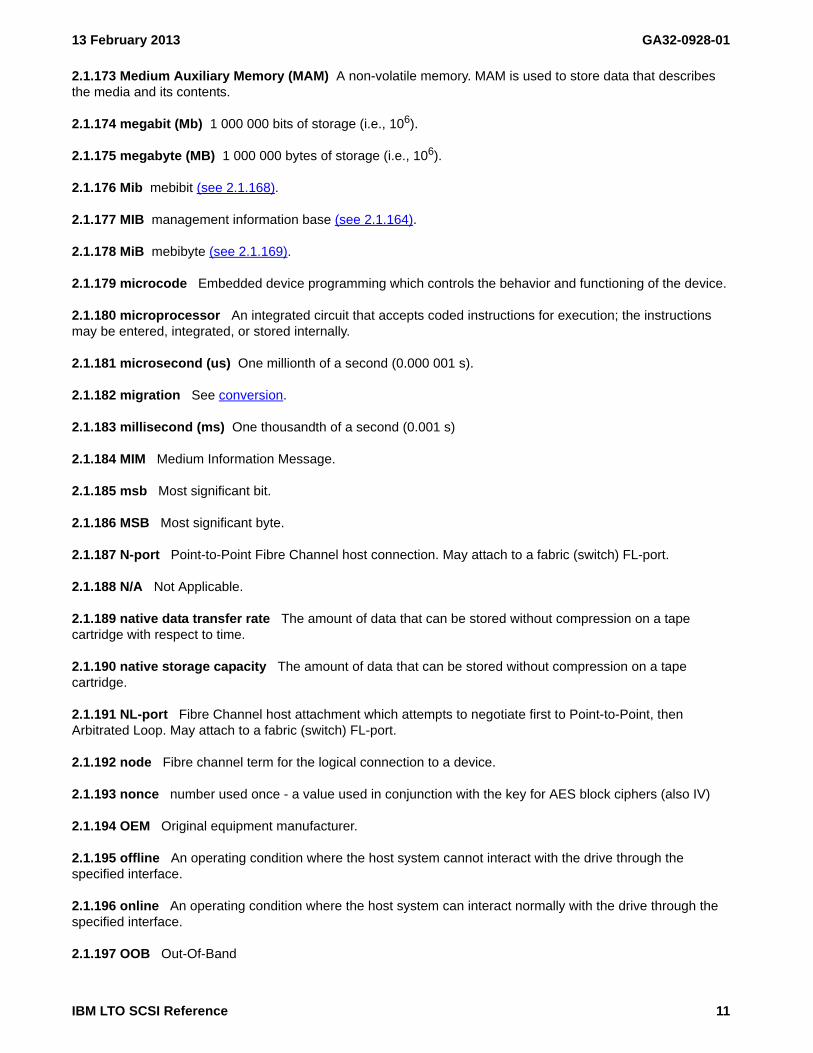
13 February 2013 GA32-0928-01
2.1.173 Medium Auxiliary Memory (MAM) A non-volatile memory. MAM is used to store data that describes the media and its contents.
2.1.174 megabit (Mb) 1 000 000 bits of storage (i.e., 106).
2.1.175 megabyte (MB) 1 000 000 bytes of storage (i.e., 106).
2.1.176 Mib mebibit (see 2.1.168).
2.1.177 MIB management information base (see 2.1.164).
2.1.178 MiB mebibyte (see 2.1.169).
2.1.179 microcode Embedded device programming which controls the behavior and functioning of the device.
2.1.180 microprocessor An integrated circuit that accepts coded instructions for execution; the instructions may be entered, integrated, or stored internally.
2.1.181 microsecond (us) One millionth of a second (0.000 001 s).
2.1.182 migration See conversion.
2.1.183 millisecond (ms) One thousandth of a second (0.001 s)
2.1.184 MIM Medium Information Message.
2.1.185 msb Most significant bit.
2.1.186 MSB Most significant byte.
2.1.187 N-port Point-to-Point Fibre Channel host connection. May attach to a fabric (switch) FL-port.
2.1.188 N/A Not Applicable.
2.1.189 native data transfer rate The amount of data that can be stored without compression on a tape cartridge with respect to time.
2.1.190 native storage capacity The amount of data that can be stored without compression on a tape cartridge.
2.1.191 NL-port Fibre Channel host attachment which attempts to negotiate first to Point-to-Point, then Arbitrated Loop. May attach to a fabric (switch) FL-port.
2.1.192 node Fibre channel term for the logical connection to a device.
2.1.193 nonce number used once - a value used in conjunction with the key for AES block ciphers (also IV)
2.1.194 OEM Original equipment manufacturer.
2.1.195 offline An operating condition where the host system cannot interact with the drive through the specified interface.
2.1.196 online An operating condition where the host system can interact normally with the drive through the specified interface.
2.1.197 OOB Out-Of-Band
IBM LTO SCSI Reference 11

GA32-0928-01 13 February 2013
2.1.198 open system Computer systems whose operating standards and methods are not proprietary.
2.1.199 operating system The master computer control program that translates the user commands and allows software application programs to interact with the computer hardware and attached devices.
2.1.200 OSI Open Systems Interconnection - (see X.200 standard)
2.1.201 overwrite A write operation that records a logical object in a logical position that is not an append point (see 4.1.3).
2.1.202 parity The state of being even-numbered or odd-numbered. A parity bit is a binary number that is added to a group of binary numbers to make the sum of that group always odd (odd parity) or even (even parity).
2.1.203 PEOT physical end of tape (PEOT)
2.1.204 physical end of tape (PEOT) A point on the tape beyond which the tape is not permitted to move.
2.1.205 PKCS Public-Key Cryptography Standards
2.1.206 POR Power-on reset.
2.1.207 port Fibre channel or SAS term for the physical connection to a device.
2.1.208 power-off To remove electrical power from a device.
2.1.209 power-on To apply electrical power to a device.
2.1.210 powered-on The state of a device when power has been applied to it.
2.1.211 primed Pertaining to a condition of a tape drive when the controlling computer addresses the drive but the drive is not in a ready state.
2.1.212 PRNG Pseudo Random Number Generator
2.1.213 processing application The execution of a systematic sequence of operations performed on data to accomplish a specific purpose.
2.1.214 Program Temporary Fix A temporary solution to a problem in the microcode.
2.1.215 protocol The meanings of, and the sequencing rules for, requests and responses that are used to manage a network, transfer data, and synchronize the states of network components.
2.1.216 PTF Program Temporary Fix
2.1.217 quiesce To bring a device or system to a halt by a rejection of new requests for work.
2.1.218 read To acquire or interpret data from a storage device, from a data medium, or from another source.
2.1.219 read-type commands Any commands that cause data to be read from tape.
2.1.220 reboot To reinitialize the execution of a program by repeating the initial program load (IPL) operation.
2.1.221 record A collection of related data or words, treated as a unit; for example, in stock control, each invoice could constitute one record.
2.1.222 recording density The number of bits in a single linear track measured per unit of length of the recording medium.
12 IBM LTO SCSI Reference

13 February 2013 GA32-0928-01
2.1.223 reset To return a device, circuit, or value to a clear state.
2.1.224 retension (or refresh) The process or function of tightening the tape onto the cartridge, if it is sensed that the tape has a loose wrap on the cartridge.
2.1.225 RS-422 connector Located at the rear of the device, the connector to which the internal RS-422 cable of an enclosure connects. The connection enables serial devices to communicate with the drive.
2.1.226 RS-422 interface An electrical interface standard that is approved by the Electronic Industries Association (EIA) for connecting serial devices. The RS-422 standard, which supports higher data rates and greater immunity to electrical interference, is an alternative to the older RS-232 interface, and uses individual differential signal pairs for data transmission. Depending on data transmission rates, RS-422 can be used at distances up to 1,275 m (4,000 ft). The RS-422 interface also supports multi-point connections.
2.1.227 RSA Method authored by Rivest, Shamir, Adleman
2.1.228 s second
2.1.229 SAN Storage Area Network.
2.1.230 SAS Serial Attached SCSI
2.1.231 SCSI Small Computer System Interface.
2.1.232 SCSI address The octal representation of the unique address (0-F) assigned to a SCSI device. This address would normally be assigned and set in the SCSI device during system installation.
2.1.233 SCSI device A host adapter or a target controller that can be attached to the SCSI bus.
2.1.234 SCSI ID The identifier used to uniquely identify the address on the bus. When used on Fibre Channel devices this refers to the AL_PA.
2.1.235 SCSI Sense Data In response to a command from the server, a packet of SCSI sense bytes that contains information about the error that is sent back to the server by the drive in autosense. SCSI Sense Data may also be returned by the REQUEST SENSE command, but that sense data is usually no sense.
2.1.236 sense data See SCSI sense data (see 2.1.235).
2.1.237 Serial Attached SCSI (SAS) A transport for exchanging information between SCSI devices using a serial interconnect.
2.1.238 server A functional unit that provides services to one or more clients over a network. Synonymous with host system (see 2.1.123).
2.1.239 SHA Secure Hash Algorithm (can be SHA-256, SHA-384, SHA-512, for bit size)
2.1.240 SIM Service Information Message.
2.1.241 Small Computer Systems Interface (SCSI) A standard used by computer manufacturers for attaching peripheral devices (such as tape drives, hard disks, CD-ROM players, printers, and scanners) to computers (servers). Pronounced "scuzzy."
2.1.242 soft addressing A method of specifying a standard arbitration method for assigning an address for a device in a Fibre Channel loop configuration.
2.1.243 software Programs, procedures, rules, and any associated documentation pertaining to the operation of a computer system.
IBM LTO SCSI Reference 13

GA32-0928-01 13 February 2013
2.1.244 special feature A specific design addition to an IBM product that is quoted in the IBM Sales Manual and ordered separately.
2.1.245 standard function The significant design elements of an IBM product that are included as part of the basic standard product.
2.1.246 Storage Area Network (SAN) A high-speed subnetwork of shared storage devices. A SAN’s architecture makes all storage devices available to all servers on a LAN or WAN. As more storage devices are added to a SAN, they too will be accessible from any server in the larger network. Because stored data does not reside directly on any of a network’s servers, server power is used for business applications, and network capacity is released to the end user.
2.1.247 switch A network infrastructure component to which multiple nodes attach. Unlike hubs, switches typically have the ability to switch node connections from one to another. A typical switch can facilitate several simultaneous bandwidth transmissions between different pairs of nodes.
2.1.248 synchronization The process of coordinating the activities of the controlling computer and the magnetic tape subsystem to obtain the condition in which the buffer is empty and the tape is in the correct position for the next operation.
2.1.249 T10 ANSI group responsible for SCSI model and command sets, see http://www.t10.org
2.1.250 T11 ANSI group responsible for FCP/fibre channel protocols, see http://www.t11.org
2.1.251 tape Commonly refers to magnetic tape or the tape cartridge.
2.1.252 tape cartridge A container holding magnetic tape that can be processed without separating it from the container.
2.1.253 tape drive A device that is used for moving magnetic tape and includes the mechanisms for writing and reading data to and from the tape.
2.1.254 tape unit A device that contains tape drives and their associated power supplies and electronics.
2.1.255 TapeAlert A patented technology and ANSI standard that defines conditions and problems that are experienced by tape drives.
2.1.256 TapeAlert flags Status and error messages that are generated by the TapeAlert utility and are reported to a host system.
2.1.257 target A SCSI device that performs an operation requested by the initiator.
2.1.258 target routine A target routine is an I/O process directed to a target, and not to a logical unit.
2.1.259 topology In communications, the physical or logical arrangement of nodes in a network, especially the relationships among nodes and the links between them.
2.1.260 transfer rate See data transfer rate (see 2.1.61).
2.1.261 TRNG True Random Number Generator
2.1.262 TSM Tivoli Storage Manager
2.1.263 uniform resource locator (URL) The address of an item on the World Wide Web. It includes the protocol followed by the fully qualified domain name (sometimes called the host name) and the request. The web
14 IBM LTO SCSI Reference

13 February 2013 GA32-0928-01
server typically maps the request portion of the URL to a path and file name. For example, if the URL is http://www.networking.ibm.com/nsg/nsgmain.htm, the protocol is http; the fully qualified domain name is www.networking.ibm.com; and the request is /nsg/nsgmain.htm.
2.1.264 unload The act (performed by the drive) of unthreading tape from the drive’s internal tape path and returning it (with the leader block) to the tape cartridge.
2.1.265 URL See uniform resource locator (see 2.1.263).
2.1.266 universal time (UT) The time at longitude zero, colloquially known as Greenwich Mean Time. See http://www.usno.navy.mil/USNO/time/master-clock/systems-of-time.
2.1.267 vital product data Non-volatile information including configuration, calibration, etc., used to control the behavior and operation of the device.
2.1.268 volume (1) A certain portion of data, together with its data carrier, that can be handled conveniently as a unit. (2) A data carrier that is mounted and demounted as a unit, for example, a reel of magnetic tape, a disk pack.
2.1.269 volume coherency set: A set of information contained in logical objects including a volume coherency count (see 4.17) for which coherency across an entire volume is desired.
2.1.270 VPD Vital Product Data - information stored in drive nonvolatile memory
2.1.271 web See World Wide Web (see 2.1.273).
2.1.272 World Wide Name A unique, 8-byte identifier that is assigned by IBM Manufacturing to each tape drive and used to identify a drive.
2.1.273 World Wide Web (www) A network of servers that contain programs and files. Many of the files contain hypertext links to other documents that are available through the network.
2.1.274 WORM (Write Once, Read Many) A write or append methodology for allowing data to be written only once, disallowing overwriting.
2.1.275 write To store or encode data to a storage device, to data medium, or to another source.
2.1.276 Write Once, Read Many (WORM) A write or append methodology for allowing data to be written only once, disallowing overwriting.
2.1.277 write protected A state disallowing write operations to a device or medium.
2.1.278 write-type commands Any commands that cause data to be written on tape or affect buffered write data.
IBM LTO SCSI Reference 15

GA32-0928-01 13 February 2013
2.2 Conventions
2.2.1 Bit Numbering
Bit numbering follows ANSI standards as follows:
• Bit 7 is the most significant bit (MSB) occupying the leftmost bit position in the diagrams
• Bits 6 through 1 continue from left to right in descending order
• Bit 0 is the least significant bit (LSB) occupying the rightmost bit position in the diagrams
2.2.2 Units of measure for data storage
Decimal units such as KB, MB, GB, and TB have commonly been used to express data storage values, though these values are more accurately expressed using binary units such as KiB, MiB, GiB, and TiB. At the kilobyte level, the difference between decimal and binary units of measurement is relatively small (2.4%). This difference grows as data storage values increase, and when values reach terabyte levels the difference between decimal and binary units approaches 10%.
This document represents values using both decimal units and binary units. Values are represented by the following formats:
a) for decimal units: 1) numeric value;2) space;3) decimal prefix or decimal symbol (see table 3); and4) unit (e.g., byte or B);5) (;6) decimal power (e.g., 106);7) )
o) for binary units:1) numeric value;2) space;3) binary prefix or binary symbol (see table 3); and4) unit (e.g., byte or B);5) (;6) binary power (e.g., 220);7) );
p) for an indication that all values in a row of a table are decimal units:1) (;2) decimal power (e.g., 106);3) )
q) for an indication that all values in a row of a table are binary units:1) (;2) binary power (e.g., 220);3) );
As an example:
a) for decimal units:
the value 3.5 terabytes is displayed as 3.5 TB (1012);r) for binary units:
the value 400 mebibytes per second is displayed as 400 MiB/sec (220)
16 IBM LTO SCSI Reference

13 February 2013 GA32-0928-01
s) for an indication that all values in a row of a table are decimal units:
t) for an indication that all values in a row of a table are binary units:
Table 3 compares the names, symbols, and values of the binary and decimal units. Table 4 shows the increasing percentage of difference between binary units and decimal units.
Table 1 — Density information
FieldPRIMARY DENSITY CODE
51h 1 52h 2 53h 3 54h 4
…
CAPACITY
in MB (106)0004_93E0h 0 000A_AE60h 0 000F_4240h 0 0035_67E0h 0
…
a Value when MEDIA = 0b
Table 2 — Differences between products
ItemDevice model
J1A E05 E06 E07
…Read/Write buffer size 1 128 512 1024 1024
…
a Values are in MiB (220).
Table 3 — Comparison of binary and decimal units and values
Decimal Binary
Name SymbolValue
(base-10)Name Symbol
Value(base-2)
kilo K 103 kibi Ki 210
mega M 106 mebi Mi 220
giga G 109 gibi Gi 230
tera T 1012 tebi Ti 240
peta P 1015 pebi Pi 250
exa E 1018 exbi Ei 260
Table 4 — Percentage difference between binary and decimal units
Decimal Value Binary ValuePercentageDifference
100 kilobytes (KB) 97.65 kibibytes (KiB) 2.35%
100 megabytes (MB) 95.36 mebibytes (MiB) 4.64%
100 gigabytes (GB) 93.13 gibibytes (GiB) 6.87%
100 terabytes (TB) 90.94 tebibytes (TiB) 9.06%
100 petabytes (PB) 88.81 pebibytes (PiB) 11.19%
100 exabytes (EB) 86.73 exbibytes (EiB) 13.27%
IBM LTO SCSI Reference 17

GA32-0928-01 13 February 2013
2.2.3 Subpages
When pages have subpages (e.g., Mode Pages, Log Pages) the convention used for Page XXh Subpage YYh is Page XXh[YYh].
When describing Security Protocol XXh with Security Protocol Specific YYYYh in the Security Protocol In command or the Security Protocol Out command XXh[YYYYh] is used.
2.2.4 Text Markers
The source files of this document contains conditional text to aid in maintaining the various versions that are generated from these files. During editing and review, these conditional texts have specific markers that delineate which condition they relate to. These markers include color, underlines, overlines, etc. Those markers contained in this version of the document are:
a) Text contained in all versions of the document (Unconditional)b) Text contained in the external version that is replaced by text in the encryption version of the document
(Crypto-Removed)c) Text in the external version that is replaced by text in the Internal version of the document
(Internal-Removed)d) Text that is removed due to an FCR that had not yet been implemented in code (Future-Removed)
2.2.5 Hyperlinks
This document contains many hyperlinks. Every place the text says “see clause number” should be a hyperlink. Hyperlinks have been given a special font to offset them from the rest of the text. That font is demonstrated in this following link (see 2.2.5)
18 IBM LTO SCSI Reference

13 February 2013 GA32-0928-01
2.3 Tape Drive Model Names
From this section forward, through the remainder of this book, LTO5 Tape Drive models are referred to collectively as the LTO tape drive, the Ultrium tape drive or the 3580 tape drive. LTO5 has both a Full-High version and a Half-High version, they will be referred to as FH for Full-High and HH for Half-High.
IBM LTO SCSI Reference 19

GA32-0928-01 13 February 2013
20 IBM LTO SCSI Reference

13 February 2013 GA32-0928-01
3. Introduction
3.1 Drive Overview
The products that are discussed in this book are high-performance, high-capacity data-storage devices that connect to and provide additional storage for supported servers. They include the LTO5 and LTO6 models of the IBM® LTO Ultrium Tape Drive.
All products use the Small Computer Systems Interface (SCSI) Architecture Model. The transports used are shown in table 5.
Figure 1 shows the IBM 3580 Ultrium Tape Drive and the IBM System Storage LTO Ultrium Tape Drive Model T200. The IBM System Storage TS2350 Tape Drive Express is similar to the IBM System Storage LTO Ultrium Tape Drive Model T200 and the IBM System Storage TS2250 Tape Drive Express is half the height.
Figure 1 — IBM System Storage Ultrium Tape Drive Models.
Designed to perform unattended backups as well as to retrieve and archive files, the Ultrium Tape Drives include the features that are described in table 5.
Table 5 — Features of the IBM Ultrium Tape Drives and the IBM 3580 Ultrium Tape Drive (part 1 of 2)
Feature Ultrium 5Ultrium 5
Half-HeightUltrium 6
Ultrium 6Half-Height
Native storage capacity 1500 GB 1500 GB 2500 GB 2500 GB
Storage capacity when compression is enabled a 3.0 TB 3.0 TB 6250 GB 6250 GB
Native sustained data transfer rate 140 MB/s 140 MB/s 160 MB/s 160 MB/s
Data transfer rate when compression is enabled a 280 MB/s 280 MB/s 400 MB/s 400 MB/s
Burst data transfer rate (1GFC) 100 MB/s 100 MB/s 100 MB/s 100 MB/s
Burst data transfer rate (2GFC) 200 MB/S 200 MB/S 200 MB/S 200 MB/S
IBM LTO SCSI Reference 21
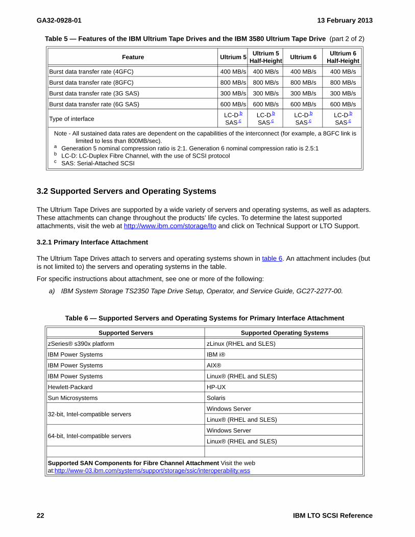
GA32-0928-01 13 February 2013
3.2 Supported Servers and Operating Systems
The Ultrium Tape Drives are supported by a wide variety of servers and operating systems, as well as adapters. These attachments can change throughout the products’ life cycles. To determine the latest supported attachments, visit the web at http://www.ibm.com/storage/lto and click on Technical Support or LTO Support.
3.2.1 Primary Interface Attachment
The Ultrium Tape Drives attach to servers and operating systems shown in table 6. An attachment includes (but is not limited to) the servers and operating systems in the table.
For specific instructions about attachment, see one or more of the following:
a) IBM System Storage TS2350 Tape Drive Setup, Operator, and Service Guide, GC27-2277-00.
Burst data transfer rate (4GFC) 400 MB/s 400 MB/s 400 MB/s 400 MB/s
Burst data transfer rate (8GFC) 800 MB/s 800 MB/s 800 MB/s 800 MB/s
Burst data transfer rate (3G SAS) 300 MB/s 300 MB/s 300 MB/s 300 MB/s
Burst data transfer rate (6G SAS) 600 MB/s 600 MB/s 600 MB/s 600 MB/s
Type of interfaceLC-D b
SAS cLC-D b
SAS cLC-D b
SAS cLC-D b
SAS c
Note - All sustained data rates are dependent on the capabilities of the interconnect (for example, a 8GFC link is limited to less than 800MB/sec).
a Generation 5 nominal compression ratio is 2:1. Generation 6 nominal compression ratio is 2.5:1b LC-D: LC-Duplex Fibre Channel, with the use of SCSI protocolc SAS: Serial-Attached SCSI
Table 6 — Supported Servers and Operating Systems for Primary Interface Attachment
Supported Servers Supported Operating Systems
zSeries® s390x platform zLinux (RHEL and SLES)
IBM Power Systems IBM i®
IBM Power Systems AIX®
IBM Power Systems Linux® (RHEL and SLES)
Hewlett-Packard HP-UX
Sun Microsystems Solaris
32-bit, Intel-compatible serversWindows Server
Linux® (RHEL and SLES)
64-bit, Intel-compatible serversWindows Server
Linux® (RHEL and SLES)
Supported SAN Components for Fibre Channel Attachment Visit the web at:http://www-03.ibm.com/systems/support/storage/ssic/interoperability.wss
Table 5 — Features of the IBM Ultrium Tape Drives and the IBM 3580 Ultrium Tape Drive (part 2 of 2)
Feature Ultrium 5Ultrium 5
Half-HeightUltrium 6
Ultrium 6Half-Height
22 IBM LTO SCSI Reference

13 February 2013 GA32-0928-01
3.3 Supported Device Drivers
IBM maintains the latest levels of device drivers and driver documentation for the IBM Ultrium Tape Drives on the Internet. You can access this material from your browser or through the IBM FTP site by performing one of the following procedures. (Note: If you do not have Internet access and you need information about device drivers, contact your Marketing Representative.)
Using a browser, go to one of the following websites:
a) The IBM storage website at http://www.ibm.com/storage; orb) The IBM Fix Central website at http://www.ibm.com/support/fixcentral. This is a portal to enter the
download area. There are a few pull down menus to get you to the correct download as follows:1) in menu labeled "Product Group" select "Storage Systems";2) in menu labeled "Product Family" select "Tape Systems";3) in menu labeled "Product Type" select "Tape Device Drivers and Software";4) in menu labeled "Product" select "Tape Device Drivers";5) in menu labeled “Platform” select the correct operating system. You can select the generic form of
the platform (e.g., Linux) and all device drivers for that platform will come up;6) click continue; and7) select the checkbox(es) of the fix pack(s) needed and click continue.
IBM provides PostScript- and PDF-formatted versions of its documentation in the /storage/devdrvr/doc directory:
a) IBM_Tape_Driver_IUG.pdf contains the current version of the IBM Tape Device Drivers Installation and User’s Guide
b) IBM_Tape_Driver_PROGREF.pdf contains the current version of the IBM Tape Device Drivers Programming Reference
3.4 Supported Tape Cartridges
The IBM LTO Ultrium Tape Drives support LTO Cartridges as described in table 7
The Ultrium 6 Tape Drive (Generation 6) uses the IBM TotalStorage 2500 GB Data Cartridge, and is compatible with the cartridges of its predecessors (called Generation 4 and Generation 5). The Ultrium 6 Tape Drive performs the following functions:
a) Reads and writes Generation 6 cartridges to Generation 6 formatb) Reads and writes Generation 5 cartridges to Generation 5 formatc) Reads Generation 4 cartridges in Generation 4 formatd) Does not write Generation 6 cartridges to other generations' formate) Does not write Generation 5 cartridges to other generations' format
Table 7 — Table 3. IBM LTO Ultrium Tape Drive Support of LTO Cartridges
LTOGeneration
TypeData
CapacityNative
DataCapacity
Compressed
Supported by
Ultrium 5 Drive Ultrium 6 Drive
6 A 2500 GB 6250 GB No Write and Read
5 A 1500 GB 3000 GB Write and Read Write and Read
4 A 800 GB 1600 GB Write and Read Read Only
3 A 400 GB 800 GB Read Only No
Ultrium Tape Drives reads tapes that have been written by other licensed Ultrium drives.Ultrium Tape Drives write tapes that can be read by other licensed Ultrium drives.Ultrium Tape Drives offer read/write capability for certified LTO Ultrium tape cartridges as specified in this table.The tape cartridges define the format to which it is written. (for example Ultrium 4 cartridges can only be written to Ultrium 4 format regardless of which generation drive writes it.
IBM LTO SCSI Reference 23

GA32-0928-01 13 February 2013
f) Does not write Generation 4 cartridgesg) Does not write or read Generation 1, Generation 2, or Generation 3 cartridges in any format
The Ultrium 5 Tape Drive (Generation 5) uses the IBM TotalStorage 1500 GB Data Cartridge, and is compatible with the cartridges of its predecessors (called Generation 3 and Generation 4). The Ultrium 5 Tape Drive performs the following functions:
a) Reads and writes Generation 5 cartridges to Generation 5 formatb) Reads and writes Generation 4 cartridges to Generation 4 formatc) Reads Generation 3 cartridges in Generation 3 formatd) Does not write Generation 5 cartridges to other generations' formate) Does not write Generation 4 cartridges to other generations' formatf) Does not write Generation 3 cartridgesg) Does not write or read Generation 1 cartridges or Generation 2 cartridges in any format
3.5 Microcode Detection of Errors
The drive microcode is designed to check for logic errors, to handle hardware-detected errors, and to detect and report microcode-related errors.
3.5.1 Fencing Behavior
For a description of the Fencing Behavior and Persistent Error handling, see Persistent Errors.
24 IBM LTO SCSI Reference

13 February 2013 GA32-0928-01
4. Implementation Considerations
4.1 Write modes
4.1.1 Write mode introduction
Write modes of the device entity specify the allowable behaviors for altering logical objects on a mounted volume. When the write mode rules allow altering of logical objects then the operation shall be processed following the write protection rules defined in SSC-4 clause 4.2.14 (i.e., Write Protection).
4.1.2 Overwrite-allowed mode
Overwrite-allowed mode is used to allow alteration of any logical object on the medium. Overwrite-allowed mode is enabled or disabled using the WRITE MODE field of the Device Configuration Extension mode page (see 6.6.12). This mode is set in the device entity to enable device server behaviors. The overwrite-allowed mode does not modify the volume. When the volume is removed from the device no indication of whether overwrite-allowed mode is enabled or disabled is carried with the volume.
When overwrite-allowed mode is enabled in the drive, then any command that would result in a write shall be processed normally. If the mounted volume is a WORM volume, then a write type command shall be processed following the WORM rules.
4.1.3 Append-only mode (also known as Data-safe mode)
Append-only mode is used to protect data from being accidently overwritten. Sometimes, due to errors in the configuration of the environment an application client attempts to rewind a drive that it is not transferring data to. Without append-only mode, if the application client writing to the logical unit has not reserved the logical unit, then a different application client is allowed to rewind the volume causing an accidental overwrite of the medium. With append-only mode enabled, the medium is not allowed to be overwritten.
Append-only mode is enabled or disabled using the WRITE MODE field of the Device Configuration Extension mode page (see 6.6.12).This mode is set in the device server to enable device server behaviors. The append-only mode does not modify the volume. When the volume is removed from the device it behaves as a normal volume.
When append-only mode is enabled in the drive, then any command that would result in a write to a location that is not an append point shall be rejected with a CHECK CONDITION, DATA PROTECT, OPERATOR SELECTED WRITE PROTECT (7h / 5A02h) and TapeAlert 09h shall be set. An append point shall be:
a) the logical position zero if there are no logical objects beyond BOP;b) the current logical position if:
A) the current logical position is at BOP; andB) there are only filemarks between the current logical position and EOD;
c) the current logical position if:A) the current logical position is between BOP and EOD;B) there are only filemarks from the current logical position to EOD; andC) there is at least one filemark immediately before the current logical position;
or
d) the current logical position if the current logical position is at EOD.
IBM LTO SCSI Reference 25

GA32-0928-01 13 February 2013
The device server maintains an allow_overwrite variable. The allow_overwrite variable defines what operation is currently allowed when in append-only mode. The allow_overwrite variable values are defined in table 8.
The allow_overwrite_position variable specifies the position (i.e., partition and logical object identifier) at which a write to a position that is not an append point is allowed.
Append-only mode is a function of the device server and is not a function of the volume. Append-only mode may be used when accessing Data Volumes or WORM volumes. An application client may overwrite data by using a special command called the ALLOW OVERWRITE command (see 5.2.1). The ALLOW OVERWRITE command specifies the logical position where the overwrite is to occur. After succesfully processing an ALLOW OVERWRITE command, a write type command at the specified position is processed normally. If the position of the medium is changed or the volume is unmounted, then the device server shall set the allow_overwrite variable to Disabled (i.e., 0h) and the allow_overwrite_position variable to invalid. The ALLOW OVERWRITE command requires the partition number and the logical position to be passed in the CDB. If the position information passed in the ALLOW OVERWRITE command does not specify the current position of the medium, then the command is terminated with CHECK CONDITION status with the sense key set to ILLEGAL REQUEST and the additional sense code set to SEQUENTIAL POSITIONING ERROR. If there is no volume loaded and the device server processes an ALLOW OVERWRITE command, then the command is terminated with CHECK CONDITION status with sense key set to NOT READY.
An ALLOW OVERWRITE command that returns GOOD status shall:
a) set the allow_overwrite variable to the value in the ALLOW OVERWRITE field of the ALLOW OVERWRITE command; and
b) set the allow_overwrite_position variable to the current position.
An ALLOW OVERWRITE command that returns a CHECK CONDITION shall:
a) set the allow_overwrite variable to Disabled (i.e., 0h); andb) set the allow_overwrite_position to invalid.
Table 8 — allow_overwrite variable definition
Name Description
Disabled A write type operation at a position that is not an append point is not allowed.
Current PositionA write type operation is allowed at the position specified by the allow_overwrite_position variable.
Format An operation that modifies the format of the medium is allowed
26 IBM LTO SCSI Reference

13 February 2013 GA32-0928-01
If append-only mode is enabled, the mounted volume is a WORM volume, and the allow_ovewrite variable is not set to Disabled, then a write type command shall be processed following the WORM rules. Figure 2 shows a representative flowchart of append-only mode behavior.
Figure 2 — Append-only mode flowchart
If the ALLOW OVERWRITE command is received by the device server and append-only mode is not enabled, the command will be rejected with CHECK CONDITION, ILLEGAL REQUEST, ILLEGAL COMMAND WHEN NOT IN APPEND-ONLY MODE.
When in append-only mode the allow_overwrite variable shall be set to Disabled (i.e., 0h) and the allow_overwrite_position variable shall be set to invalid if:
a) the WRITE MODE field of the Device Configuration Extension mode page changes to a value of 01h (i.e., The write-type operation shall only allow appends as specified for the append-only mode in 4.1.3);
b) a change in logical position occurs;c) a volume changes state from unmounted to mounted;d) the CDB of a write type command is validated and the write processing begins; ore) an ALLOW OVERWRITE command returns a CHECK CONDITION.
Yes
Yes
Command Received
Is medium positioned at an append point?
Does command
return GOOD status?
No
Iscmd a write type
command?
Fail command with CC, DATA PROTECT,
OPERATOR SELECTED WRITE
PROTECT
Isallow_overwrite =
Current Position (i.e., 1h) and allow_overwrite_position
= the current position?
Yes
No
Process Command
Process Command
Disable overwrite at a non-append point
(allow_overwrite = ‘Disabled’allow_overwrite_position = invalid)
Iscmd ALLOW OVERWRITE
cmd?
YesNo
Check Condition the command
Does the command
processing effect multiple
partitions?
No
Isallow_overwrite = Format (i.e.,
2h)?
No
Yes
Yes
Append-only mode enabled
No
Doesthe logical position
change or does a volume change from unmounted
to mounted?
NoYesNo
Yes
Note: overwrite at a non-append point is enabled as ALLOW OVERWRITE command set either:a) allow_overwrite = Current Position (i.e., 1h) and allow_overwrite_position = the current position; orb) allow_overwrite = Format (i.e., 2h)
Note: If current position changes since ALLOW OVERWRITE command then allow_overwrite = ‘Disabled’ so this decision box could really omit the check against allow_overwrite_position
IBM LTO SCSI Reference 27

GA32-0928-01 13 February 2013
4.2 Volume partitioning
4.2.1 Volume partitioning overview
Starting with LTO 5 volume partitioning is supported by the device on certain media types. A volume is recorded in the same format for the entire volume as indicated by the primary density code (see 5.2.24) but each partition may have differences in how it is encrypted. An entire partition is recorded with the same encryption method.
The device supports wrap-wise partitioning (see 4.2.2).
This clause and its subclauses describe partitioning and its relationship to:
a) capacity scaling (see 4.2.3);b) media types (see 4.2.4);c) reformatting (see 4.2.5); andd) encryption (see 4.2.6).
4.2.2 Wrap-wise Partitioning
Wrap-wise partitioning uses the length of the medium that is available for user data to create each partition. By default, this is the full length of the medium but the length available for user data may have been shortened through capacity scaling (see 4.2.3). Wrap-wise partitioning is shown logically in figure 3.
Figure 3 — Wrap-wise partitioning
Wrap-wise partitioning generally uses a minimum of two wraps and generally has a guard wrap of two wraps between each partition. The amount of usable capacity may be reduced depending on various factors including volume generation (e.g., up to 2.5% per partition boundary for Ultrium 5 volumes).
When using wrap-wise partitioning an Ultrium 5 volume supports one or two partitions and an Ultrium 6 volume supports a maximum of four partitions with any number of partitions between one and four inclusive.
Partition 0
Partition 1Guard wraps
Partition 2
Partition 3
28 IBM LTO SCSI Reference

13 February 2013 GA32-0928-01
Table 9, and table 10 show the partition sizes that result from a MODE SELECT of the Medium partition mode page (see 6.6.13) with the indicated field settings.
Table 9 — Partition sizes for wrap-wise partitioning (selection fields)
Ref a FDP SDP IDP
ADDITIONAL
PARTITIONS
DEFINED b
PARTITION SIZE
(first) (second) (third) (last)
row1 1 0 0 X
X X X X
row2
0 1 0
00h
row3 01h
row4 02h
row5 03h
row6
0 0 1
00hFFFFh
0
0
0
row7 s c
row8
01h
s FFFFh
row9 FFFFh t
row10 s c t c
row11
02h
s t FFFFh
row12 s FFFFh u
row13 FFFFh t u
row14 s c t c u c
row15
03h
s t u FFFFh
row16 s t FFFFh v
row17 s FFFFh u v
row18 FFFFh t u v
row19 s c t c u c v c
others All other combinationsa The Ref column is the reference that ties the rows in this table to the corresponding rows in table 10.b When more than one partition is defined there may be overhead that results in a loss of capacity c Value must be exact partition size allowed and when summed with other values in the row equal full capacity. This
permits a MODE SENSE followed by a MODE SELECT with no change. It is highly recommended that this method only be used in the case where the MODE SELECT data is a return of the MODE SENSE data.
IBM LTO SCSI Reference 29

GA32-0928-01 13 February 2013
Table 10 — Partition sizes for wrap-wise partitioning (resultant sizes) (part 1 of 2)
Ref a Partition 0 b Partition 1 b Partition 2 b Partition 3 b
row1s=K*n;
where n=N2t=K - -
row2 CMAX -
row3s=K*n;
where n=integer of {(N2+1)/2}
t=K*m;where m=N2+1-n
-
row4s=K*n;
where n=integer of {(N3+2)/3}
t=K*m;where m=integer of
{(N3+2)/3}
s=K*u;where u=N3+2-n-m
-
row5s=K*n;
where n=integer of {(N4+3)/4}
t=K*m;where m=integer of
{(N4+3)/4}
s=K*u;where u=integer of
{(N4+3)/4}
s=K*v;where v=N4+3-n-m-u
row6 CMAX-
row7 CMAX
row8s=K*n;
where 1<=n<=N2
CMAX - overhead-(partition size 0)
-row9
CMAX - overhead-(partition size 1)
t=K*m;where 1<=m<=N2
row10s=K*n;
where 1<=n<=N2 and n+m=N2+1
t=K*m;where 1<=m<=N2 and
n+m=N2+1
row11
s=K*n;where 1<=n<=N3
t=K*m;where 1<=m<=N3
CMAX - overhead-(partition size 0)-(partition size 1)
-
row12CMAX - overhead-(partition size 0)-(partition size 2) u=K*p;
where 1<=p<=N3
row13CMAX - overhead-(partition size 1)-(partition size 2)
t=K*m;where 1<=m<=N3
row14s=K*n;
where 1<=n<=N3 and n+m+p=N3+2
t=K*m;where 1<=m<=N3 and
n+m+p=N3+2
u=K*p;where 1<=p<=N3 and
n+m+p=N3+2a The values in the Ref column refer back to the associated row in table 9.b The values for CMAX, K, N2, N3, N4, and the sum of existing partitions are specified in table 11.
30 IBM LTO SCSI Reference

13 February 2013 GA32-0928-01
4.2.3 Partitioning and capacity scaling
Partitioning of volumes is supported on capacity scaled volumes. If a volume has been capacity scaled through the use of the SET CAPACITY command (see 5.2.33), the medium available for use to record user data is reduced and partitioning functions within those bounds. The act of processing a SET CAPACITY command removes any partitions that may exist and changes the medium available for use to record user data. The resultant volume contains a single partition which may subsequently be partitioned using the Medium partition mode page (see 6.6.13) and the FORMAT MEDIUM command (see 5.2.3).
row15
s=K*n;where 1<=n<=N4
t=K*m;where 1<=m<=N4
u=K*p;where 1<=p<=N4
CMAX - overhead-(partition size 0)-(partition size 1)-(partition size 2)
row16
CMAX - overhead-(partition size 0)-(partition size 1)-(partition size 3)
v=K*q;where 1<=q<=N4
row17
CMAX - overhead-(partition size 0)-(partition size 2)-(partition size 3) u=K*p;
where 1<=p<=N4
row18
CMAX - overhead-(partition size 1)-(partition size 2)-(partition size 3)
t=K*m;where 1<=m<=N4
row19s=K*n;
where 1<=n<=N4 and n+m+p+q=N4+3
t=K*m;where 1<=m<=N4 and
n+m+p+q=N4+3
u=K*p;where 1<=p<=N4 and
n+m+p+q=N4+3
v=K*q;where 1<=q<=N4 and
n+m+p+q=N4+3
others Check Condition, Illegal Request, Invalid Field in Parameter Data
Table 11 — Partition values by density and media type
Parameter in table 10Primary Density Code
58h 5Ah
CMAX b 1.5 TB 2.5 TB
K a, b 37.500 GB 36.764 GB
N2 38 66
N3 N/A 64
N4 N/A 62
Sum of all partitions a, b
s+t+[u]+[v]s+t=1 462.500 GB
s+t=2 463.235 GBs+t+u=2 426.470 GB
s+t+u+v=2 389.705 GBa The precision of capacity values able to be expressed is limited by the 2-byte PARTITION SIZE field and the
value of the PARTITION UNITS field of the Medium Partition mode page (see 6.6.13). Actual size on medium is not limited by the precision of the fields in the mode page.
b The capacity values assume a volume that has not been capacity scaled (see 4.2.3).
Table 10 — Partition sizes for wrap-wise partitioning (resultant sizes) (part 2 of 2)
Ref a Partition 0 b Partition 1 b Partition 2 b Partition 3 b
a The values in the Ref column refer back to the associated row in table 9.b The values for CMAX, K, N2, N3, N4, and the sum of existing partitions are specified in table 11.
IBM LTO SCSI Reference 31

GA32-0928-01 13 February 2013
4.2.4 Partitioning and media types
Partitioning of volumes is supported on media in Ultrium 5 (i.e., primary density code = 58h) and Ultrium 6 (i.e., primary density code = 5Ah) logical formats only.
4.2.5 Partitioning and reformatting
Partitions are created and destroyed using the FORMAT MEDIUM command (see 5.2.3). How a volume is formatted depends on the settings in the Medium Partition mode page (see 6.6.13), if the volume is capacity scaled (see 4.2.3), and the settings in the FORMAT MEDIUM command (see 5.2.3). The FORMAT MEDIUM command specifies how to format the volume and the interactions of these conditions using the FORMAT field.
The Medium Partition mode page is used to specify the group of medium partitions. The partitioning of the mounted volume is not changed until a subsequent FORMAT MEDIUM command is issued while the volume is mounted.
The device ensures consistency of the partitioning values set in Medium Partition mode page by causing a CHECK CONDITION status with the sense key set to ILLEGAL REQUEST and the additional sense code set to PARAMETER VALUE INVALID to be returned to a subsequent FORMAT MEDIUM command attempting to use the values set in Medium Partition mode page if values in those values become inconsistent between when they were set and when the FORMAT MEDIUM command is received. The invalidation of the values in this page is accomplished by setting the FDP, SDP, and IDP bits to zero and the other values in this page to:
a) the values dictated by the format of the currently mounted volume, if a volume is mounted; orb) the default values present after power-on, if no volume is mounted.
The invalidation of values in this page occurs if:
a) the volume is capacity scaled (see 4.2.3); orb) other events that are determined to make the values in this page inconsistent.
4.2.6 Partitioning and encryption
The relationship between partitioning and encryption is described in Device Hardware Encryption (see 4.12 on page 49).
32 IBM LTO SCSI Reference

13 February 2013 GA32-0928-01
4.3 Object buffer
4.3.1 Object buffer introduction
This device contains an object buffer capable of holding logical objects being written to the medium or logical objects being transferred from the medium in read-ahead operations. The object buffer is used during write operations when the device is configured to use buffered mode (i.e., the BUFFER MODE field of the mode parameter header is set to a non-zero value per Mode Parameter Header for Mode Select (6/10) (see 6.6.1.1 on page 359))) and during read operations regardless of the buffer mode.
When the device is reading logical objects from the medium, it uses the object buffer in a read-ahead fashion to improve performance. Logical objects are read from the medium and placed into the object buffer such that they are available to an application that is reading without the application being required to wait for each block to be read from the medium prior to being transferred on the SCSI interface. Read-ahead operations often occur at the conclusion of space, locate, and load operations in order to prime the object buffer with logical objects in case a read operation follows.
4.3.2 BOP caching
Devices starting with LTO-6 use a small portion of the object buffer as a cache to retain data read at BOP while the remainder of the object buffer is used for read-ahead operations. The data around BOP, once read, is generally retained in the BOP cache until a demount or partition change. When a command is received by the device that requests access to a logical object identifier (aka, logical block address) that is in the BOP cache, that data is read from the BOP cache without requiring actual access to the medium (i.e., it uses the cached data without changing the physical location of the medium). This allows for a volume that is located away from BOP to read the data around BOP very quickly without disturbing the current physical position of the medium.
4.3.2.1 BOP caching side effects
It is important to understand the side effects that BOP caching may present:
a) Processing time to position to BOP may be transferred from the positioning command to a subsequent command (e.g., The time for a REWIND could be transferred to a subsequent UNLOAD);
b) When reading data in the BOP cache and the command requests a read through the cache boundary to data not in the cache, there may be processing time to position the medium to the proper position to read the data, as well as the time to read the data from the medium;
c) If a sequence of commands like:1) REWIND;2) READ one block;3) LOCATE to position prior to the REWIND;4) READ one block;5) Go to step 1,
is performed, the tape will typically move in a a sequential fashion like a READ without positioning to BOP in each iteration.
IBM LTO SCSI Reference 33

GA32-0928-01 13 February 2013
4.4 Programmable early warning
When writing, the application client may need an indication prior to early warning to allow for the application client to prepare to be ready for early warning (e.g., flush buffers in the application client).
Application clients that need this indication may request the device server to create a zone called the programmable-early-warning zone (PEWZ) by setting the PEWS field (see 6.6.8) to the requested size of the PEWZ. The EOP side of PEWZ is established at early-warning and extends towards BOP for a distance indicated by the PEWS field. See figure 4.
Figure 4 — Programmable early warning example
WARNING WARNINGIf PEWZ is used, all applications that may access the drive when a PEWZ exists, should support PEWZ or there is a risk of the application that does not support PEWZ detecting an unknown error or a diminished capacity
WARNING WARNING
when the PROGRAMMABLE EARLY WARNING error is reported.
The REW bit in the Device Configuration mode page (see 6.4.10) shall have no effect on the device server behavior in the PEWZ.
The device server shall return CHECK CONDITION status, with the sense key set to NO SENSE, the EOM bit set to one and the additional sense code set to PROGRAMMABLE EARLY WARNING DETECTED at the completion of a command that caused the medium to transition into the PEWZ if that command is:
a) WRITE(6);b) WRITE(16);c) WRITE FILEMARKS(6); ord) WRITE FILEMARKS(16).
Encountering the PEWZ shall not cause the device server to perform a synchronize operation or terminate the command. If processing this command results in any other exception condition except early-warning, the CHECK CONDITION status associated with that exception condition shall be reported instead. If early-warning is crossed prior to the PROGRAMMABLE EARLY WARNING DETECTED additional sense being reported, the PROGRAMMABLE EARLY WARNING DETECTED additional sense shall be reported before the early-warning CHECK CONDITION.
If the PROGRAMMABLE EARLY WARNING DETECTED additional sense code was not reported, the next write in PEWZ or beyond early-warning that would otherwise complete with GOOD status, shall return the programmable-early-warning CHECK CONDITION instead.
If the PEWZ is entered and exited on the BOP side before the PROGRAMMABLE EARLY WARNING DETECTED additional sense code is returned, the device server shall not report CHECK CONDITION status with the additional sense code set to PROGRAMMABLE EARLY WARNING DETECTED.
Logical objects accessible by the device serverBOP
LEOPEOP
EWPEWZ
Maximum logical object identifier
34 IBM LTO SCSI Reference

13 February 2013 GA32-0928-01
4.5 Logical block protection
4.5.1 Logical block protection overview
The device contains hardware or software that is capable of checking and generating protection information (i.e., 4-byte CRC) that is transferred with logical blocks between the device server and an application client. This protection information transferred with logical blocks is saved to the medium with each logical block and read from the medium with each logical block. This protection information is validated at the destination prior to completing the task thereby ensuring that the logical block has not been corrupted. This level of detection is not achievable by methods where the application client inserts vendor-specific data protection information in its data. Some devices support a standardized method of logical block protection (see 4.5.1.1).
4.5.1.1 Logical block protection
A device that supports using protection information in the standardized method configures this capability using MP 0Ah[F0h]: Control Data Protection (see 6.6.9 on page 373). A device server that supports using this protection information shall:
a) set the PROTECT bit in standard inquiry (see 5.2.4.1) to one;b) set the SPT field of the Extended INQUIRY Data VPD page (see 6.3.5) to 001b; andc) set the value returned in the MAXIMUM BLOCK LENGTH LIMIT field of the READ BLOCK LIMITS command to
a value which when added to the largest value supported in the LOGICAL BLOCK PROTECTION INFORMATION LENGTH field of the Control Data Protection mode page is less than or equal to the maximum length able to be represented in commands that transfer logical blocks between the application client and the device server.
4.5.2 Protection information on a volume
A recorded volume contains logical objects (see 4.2.7.1) and format specific symbols. Logical objects are application client accessible. Format specific symbols are used by the device server to provide methods for recording logical objects on the medium in a manner that allows them to be successfully read at a later date and may not be application client accessible. Format specific symbols contain information used to protect logical objects. The drive includes the protection information field as one of the format specific symbols. The format specific symbol that is the protection information field is written to the medium with each logical block. The protection information used by the drive is a 4-byte Reed-Solomon CRC (see Annex D.). The protection information field is accessible by the application client when the LOGICAL BLOCK PROTECTION METHOD field of the Control Data Protection mode page for the I_T_L nexus through which that application client communicates is set to a non-zero value. A representation of logical objects and format specific symbols is shown in figure 5.
IBM LTO SCSI Reference 35

GA32-0928-01 13 February 2013
Figure 5 — Protection information shown in relation to logical objects and format specific symbols
The device generates the protection information and adds it to a logical block before recording the logical block to the medium if the command that transferred the logical block being recorded to medium was received on an I_T_L nexus for which the LOGICAL BLOCK PROTECTION METHOD field of the Control Data Protection mode page:
a) is set to zero; orb) is set to a non-zero value and the LBP_W bit of the Control Data Protection mode page is set to zero.
The drive reads the protection information from the medium, validates it, and removes it from the logical block before transferring the logical block to the application client if the command that is requesting the transfer of a logical block being read was received on an I_T_L nexus for which the LOGICAL BLOCK PROTECTION METHOD field of the Control Data Protection mode page:
a) is set to zero; orb) is set to a non-zero value and the LBP_R bit of the Control Data Protection mode page is set to zero.
Protection information may be:
a) compressed;b) encrypted; orc) included in byte counts in log parameters.
NOTE 1 - Device side counters reported in log pages generally include bytes from the protection information at all times. Host side counters reported in log pages when CRC Protection and Logical block protection are disabled generally do not include bytes from the protection information. Host side counters reported in log pages when CRC Protection is enabled or when Logical block protection is enabled generally include bytes from the protection information.
4.5.3 Logical blocks and protection information
If the LOGICAL BLOCK PROTECTION METHOD field of the Control Data Protection mode page is set to zero for a specific I_T_L nexus, then a logical block transferred between the application client and the device server
Logical block
Logical block
Protected logical block Filemark
Stream of logical object and format-specific symbols
4-byte CRC (i.e., Protection
Information)
Protected logical block
Filemark
...
36 IBM LTO SCSI Reference

13 February 2013 GA32-0928-01
through that I_T_L nexus is defined by Table 12 if that transfer occurs in response to a:
a) WRITE(6); orb) READ(6).
If the LOGICAL BLOCK PROTECTION METHOD field of the Control Data Protection mode page is set to a non-zero value for a specific I_T_L nexus, then a logical block transferred between the application client and the device server through that I_T_L nexus is defined by Table 13 if that transfer occurs in response to a:
a) WRITE(6); orb) READ(6).
4.5.4 .Protecting logical blocks transferred during writes
If the LBP_W bit of the Control Data Protection mode page(see 6.6.9) is set to one for a specific I_T_L nexus, then each logical block transferred from the application client through that I_T_L nexus due to a WRITE(6) command contains protection information.
For the WRITE(6) command, the device server validates the protection information before the logical block is written to medium. If the FIXED bit in the CDB is set to one each logical block is validated before being written to the medium. If the validation of the protection information for a logical block fails, then the processing of the command terminates prior to writing the failed logical block to the medium. If the validation of the protection information fails, the device server reports a CHECK CONDITION status with Sense Code of Current or Deferred, the sense key set to HARDWARE ERROR and the additional sense code set to LOGICAL BLOCK GUARD CHECK FAILED.
An application client shall add the protection information on each logical block before transferring that logical block and shall increase the TRANSFER LENGTH field by the length of the logical block protection information if it has set the LOGICAL BLOCK PROTECTION METHOD field of the Control Data Protection mode page to a non-zero value and the LBP_W bit of the Control Data Protection mode page to one.
The application client should add the protection information to the logical block at the earliest point possible. If the data has had the protection information added to the logical block at some point in the application client prior to the hardware that transfers the logical block, then the protection information should be validated when it is transferred. If the validation fails, then the application client should abort the command and report a status to the user that validation failed.
Table 12 — Logical block with no protection information
ByteBit
7 6 5 4 3 2 1 0
0Data
n-1
n = the TRANSFER LENGTH field specified in CDB for variable length transfers; the BLOCK LENGTH field specified in the mode parameter header (see SPC-4) for fixed block transfers.
Table 13 — Logical block with protection information
ByteBit
7 6 5 4 3 2 1 0
0Data
n-x-1
n-xProtection Information
n-1
n = the TRANSFER LENGTH field specified in the CDB for variable length transfers; the BLOCK LENGTH field specified in the mode parameter header (see SPC-4) for fixed block transfers.x = the LOGICAL BLOCK PROTECTION INFORMATION LENGTH specified in the Control Data Protection mode page.
IBM LTO SCSI Reference 37

GA32-0928-01 13 February 2013
NOTE 2 - The device server treats the LOGICAL BLOCK PROTECTION INFORMATION field as the protection infor-mation. If the protection information is not added to the logical block, then the validation fails when the bytes used do not validate (e.g., the last 4-bytes of the logical block are treated as the CRC and the last 4-bytes of the logical block do not calculate as the CRC of the previous data)
4.5.5 Protecting logical blocks transferred during reads
If the LBP_R bit of the Control Data Protection mode page (see 6.6.9) is set to one for a specific I_T_L nexus, then the protection information is read from the medium and transferred with the logical block to the application client on that I_T_L nexus. The commands for which this applies are:
a) READ(6); andb) VERIFY(6) with the BYTCMP bit set to zero.
The protection information is validated by the device server before sending status to the command that caused the transfer of the logical block. If the FIXED bit in the CDB is set to one each logical block is validated before being transferred to the application client. If the validation of the protection information for a logical block fails, then the processing of the command is terminated prior to transferring any additional blocks to the application client. If the validation of the protection information fails, then the device server reports a CHECK CONDITION status with Sense Code of Current Sense, the sense key set to HARDWARE ERROR and the additional sense code set to LOGICAL BLOCK GUARD CHECK FAILED.
An application client should validate the protection information on each logical block at the latest point possible before using the data if it has set the LOGICAL BLOCK PROTECTION METHOD field of the Control Data Protection mode page to a non-zero value and the LBP_R bit of the Control Data Protection mode page to one.
4.5.6 File verification of protection information
An application client may verify that protection information is present on each logical block on the medium between the current position and a specified number of filemarks from the current position and that the protection information validates correctly by using the VBF and VLBPM bits of the VERIFY (6) command (see 5.2.37) and setting to one the the LBP_R bit of the Control Data Protection mode page (see 6.6.9). The device reads the medium verifying that each logical block between the current position and the nth filemark is protected with the protection information using the LOGICAL BLOCK PROTECTION METHOD specified in the Control Data Protection mode page and that the protection information validates as shown in figure 6.
Figure 6 — Example file verification of protection information
Logical block
Protected logical block
Filemark
Stream of logical object and format-specific symbols
Protected logical block
Logical block
Protected logical block
Filemark
Logical block
...
nth Filemark
Logical block
Protected logical block
Position at command invocation
First Filemark
4-byte CRC
4-byte CRC
4-byte CRC
4-byte CRC
Position at command completion4-byte CRC (i.e., Protection information) validated
38 IBM LTO SCSI Reference

13 February 2013 GA32-0928-01
4.5.7 Verification to EOD of protection information
An application client may verify that protection information is present on every logical block on the medium between the current position and EOD and that the protection information validates correctly using the VBE and VLBPM bits of the VERIFY (6) command (see 5.2.37)and setting to one the the LBP_R bit of the Control Data Protection mode page (see 6.6.9). The device reads each logical block between the current position and end-of-data verifying that each logical block is protected with the protection information using the LOGICAL BLOCK PROTECTION METHOD specified in the Control Data Protection mode page and that the protection information validates as shown in figure 7.
Figure 7 — Example verification to EOD of protection information
Logical block
Protected logical block
Filemark
Stream of logical object and format-specific symbols
Protected logical block
Logical block
Protected logical block
Filemark
Logical block
...
Logical block
Protected logical block
Filemark Filemark EOD
Position at command invocation
Position at command completion
4-byte CRC (i.e., Protection Information) validated
4-byte CRC
4-byte CRC
4-byte CRC
4-byte CRC
IBM LTO SCSI Reference 39

GA32-0928-01 13 February 2013
4.6 Multiple Port Behavior
There are two primary ports in the device and may be either Fibre Channel ports or SAS ports. The two primary ports provide alternate paths through which the logical unit(s) of the device may be reached. The ports are referred to as Port 0 (or alternately, Relative Target Port 1) and Port 1 (or alternately, Relative Target Port 2). Each port maintains its own unique settings and address.
If the device is contained in a library or medium changer, the library may enable (also known as online) or disable (also known as offline) each port independently.
When an offline port is set online, all initiators on that port receive a Unit Attention condition.
Offline ports do not generate or maintain Unit Attention conditions for initiators while the port is in an offline state.
Usage of the device with both ports online is required for dual port failover to function correctly. Generally, all initiators, regardless of port, are treated the same as multiple initiators on the same port. The exception to this is the handling of mode pages and reservations when a hard port reset condition occurs (such as loss of light, etc). The following rules are described with respect to a local interface (the host port on which the hard reset condition occurred) and a remote interface (the other host port to which the device is attached).
c) If there are no reservations when a hard reset condition occurs, all mode pages are reset. All initiators on the local interface receive a Unit Attention condition for Power On, Reset, or Device Reset Occurred. All initiators on the remote interface receive a Unit Attention condition for Mode Parameters Changed.
d) If there are one or more reservations when a hard reset condition occurs and all reservations were granted to initiators on the local interface, all mode pages are reset and all SPC-2 reservations are reset. All persistent reservations remain in effect. All initiators on the local interface receive a Unit Attention condition for Power On, Reset, or Device Reset Occurred. All initiators on the remote interface receive a Unit Attention condition for Mode Parameters Changed.
e) If there are one or more reservations when a hard reset condition occurs and one or more of the reservations were granted to an initiator on the remote interface, only those mode pages and SPC-2 reservations unique to each initiator on the local interface are reset. Mode pages and reservations unique to each initiator on the remote interface are not reset. Mode pages which are defined as common to all initiators are not reset. All initiators on the local interface receive a Unit Attention condition for Power On, Reset, or Device Reset Occurred. All initiators on the remote interface see no effects of the hard reset condition on the other interface.
40 IBM LTO SCSI Reference

13 February 2013 GA32-0928-01
4.7 Data Transfer, Block Limits, and Fixed Block Option
This device is designed to buffer multiple records. Logical blocks may be prefetched to the buffer before they are requested by a READ command or held in the buffer after they are written by a WRITE command. For successive sequential-motion operations, the presence of the buffering in the device does not adversely affect the performance of the subsystem. Non-sequential motion does not result in errors, but may result in delays because of requirements to synchronize buffers or discard read ahead data. Buffer management in the device determines when to read additional data from the medium into the buffer, or when to write data from the buffer to the medium. A logical block is not written to tape until the block is entirely received into the buffer.
When the FIXED bit of the command is set to 1b,each command transfers zero or more logical blocks. The subsystem takes appropriate action to assemble or disassemble the logical blocks being transferred over the interface so that they remain independent blocks on the medium. There is no guarantee that the group of blocks transferred by the Write command is requested as a group by a subsequent Read command, so the device must be prepared to assemble and disassemble on a block boundary. This is managed by treating all blocks and filemarks as independent from one another, both for data compaction and for recording.
When the FIXED bit of the command is set to 0b, each command transfers a single logical block.
After EOP is reached on any WRITE command, only a single block is transferred before terminating the command with check condition status 0/0000 (NO SENSE, NO ADDITIONAL SENSE INFORMATION) and EOM set to 1b.The same is true for WRITE FILEMARK commands.
The device supports a minimum logical block length of 1 and a maximum logical block length of 16 777 215 (FF FFFFh) bytes if encryption is not being used and 8 388 608 (80 0000h) bytes if encryption is being used. Any block length between the limits is also supported. Refer also to READ BLOCK LIMITS - 05h (see 5.2.16 on page 108) for further information on block sizes and limitations. The READ BLOCK LIMITS command may report a lowe maximum value depending on the devices support of Encryption and Logical Block Protection. This is done to ensure that an application will not attempt to write a larger block size than can be read when one of these features is enabled.
For read type commands, including READ and VERIFY, transfer lengths larger than the maximum device supported block size are accepted and the underlength condition rules are applied for transfer requests bigger than the actual block size. A transfer Length of 000000h indicates that no bytes/blocks are transferred. This condition is not considered an error and the logical position is not changed.
For write type commands, including WRITE, and WRITE FILEMARKS, a transfer Length of 000000h indicates that no bytes/blocks are transferred. This condition is not considered an error and the logical position is not changed.
IBM LTO SCSI Reference 41

GA32-0928-01 13 February 2013
4.8 Request Sense Information, ILI, and Command Interactions
The behavior and interactions between some of the commands and the INFORMATION and ILI fields in Request Sense are rather complicated. This section details the various commands which may set the information or ILI fields, and summarizes the relationship between such commands, their parameters, the encountered conditions, the reported status, and the expected behavior of these fields and the resulting device position.
4.8.1 General Read-Type Handling
Commands which return block data from media or the buffer to the host have the same general behavior. These commands include READ and VERIFY. The major difference between these is whether or not data is returned to the host.
The block at the current position is processed first, and subsequent blocks are processed in the order they were written (proceeding towards logical end of partition). The ending position is after the last block processed. For these commands, “after” will refer to the start of the next block towards the logical end of partition, and “before” will refer to the start of referenced block.
To illustrate this, from location 'N', a Read operation will return block 'N', and be positioned at 'N+1' (“after” N).
A successful command with a FIXED bit of 1b transfers the requested Transfer Length, times the current block length in bytes to the initiator. A successful command with a FIXED bit of 0b transfers the requested Transfer Length in bytes to the initiator. Upon completion, the logical position is “after” the last block transferred.
If SILI bit is 1b and the FIXED bit is 0b, the target performs one of the following actions:
a) Reports CHECK CONDITION status for an incorrect block length condition only if the overlength condition exists and the BLOCK LENGTH field in the mode parameter block descriptor is nonzero. The associated sense data is 0/0000 (INCORRECT LENGTH, NO SENSE DATA).
b) Does not report CHECK CONDITION status if the only error is the underlength condition, or if the only error is the overlength condition and BLOCK LENGTH field of the mode parameters block descriptor is 0b. (See note 4 on page 43.)
If the SILI bit is 1b and the FIXED bit is 1b, the target terminates the command with CHECK CONDITION status with associated sense data of 5/2400 (ILLEGAL REQUEST, INVALID FIELD IN CDB).
If the SILI bit is 0b and an incorrect length block is read, CHECK CONDITION status is returned and the ILI and VALID bits are set to 1b in the sense data. Upon termination, the logical position is “after” the incorrect length block. If the FIXED bit is 1b, the INFORMATION field is set to the requested Transfer Length, minus the actual number of blocks read (not including the incorrect length block).
If the FIXED bit is 0b, the INFORMATION field is set to the requested Transfer Length, minus the actual block length in two's complement format.
If the logical unit encounters a filemark during a command, CHECK CONDITION status is returned and the FILEMARK and VALID bits are set to 1b in the sense data. The associated sense data is set to 0/0001 (NO SENSE, FILEMARK DETECTED). Upon termination, the logical position is “after” the filemark. If the FIXED bit is 1b, the INFORMATION field is set to the requested Transfer Length, minus the actual number of blocks read (not including the filemark). If the FIXED bit is 0b the INFORMATION field is set to the requested Transfer Length.
If the logical unit encounters end-of-partition during a command, CHECK CONDITION status is returned and the EOM and VALID bits are set to 1b in the sense data. Associated sense data is set to 3/0002 (MEDIUM ERROR, END OF PARTITION/MEDIUM).
If the logical unit encounters early warning and the REW bit is set to 1 in the Device Configuration mode page, CHECK CONDITION status is returned and the EOM and VALID bits are set to 1b in the sense data. Associated sense data is set to D/0002 (OVERFLOW, END-OF-PARTITION/MEDIUM DETECTED). If the FIXED bit is 1b, the INFORMATION field is set to the requested Transfer Length, minus the actual number of blocks transferred. If the FIXED bit is 0b, the INFORMATION field is set to the requested Transfer Length.
42 IBM LTO SCSI Reference

13 February 2013 GA32-0928-01
If the drive encounters End-of-Data (EOD) while processing this command, the command is terminated at the EOD position and CHECK CONDITION status is returned with associated sense data of 8/0005 (BLANK CHECK, END-OF-DATA DETECTED).
If the logical unit encounters beginning-of-partition during a command, CHECK CONDITION status is returned and the EOM and VALID bits are set to 1b in the sense data. Associated sense data is set to 0/0004 (NO SENSE, BEGINNING OF PARTITION/MEDIUM).
NOTE 3 - Because the residue information normally provided in the INFORMATION field of the sense data may not be available when the SILI bit is set, use other methods to determine the actual block length. For example: include length information in the data block itself, or in the case of underlength transfers, the host adapter or device driver may return accurate transfer length information.
NOTE 4 - In the case of the FIXED bit of 1b with an overlength condition, only the position of the incorrect-length logical block can be determined from the sense data. The actual length of the incorrect block is not reported, and also cannot be derived from the transfer length (the device truncates the overlength block to match the current block length from the mode header). Other means may be used to determine the actual length (for example, backspace and read it again with FIXED bit set to 0b).
4.8.2 Interactions Summary
The following table summarizes various commands with the specified options, the encountered conditions, and the expected results.
Table 14 — Information and ILI Behavior Summary (part 1 of 3)
Scenario Fixed SILI Block
Length SenseError1
Information1 2 FlagsIFE1
Position1
reportable UA X X X UA not valid (0) - unchanged (no command)
reportable DCC
X X X DCC not valid (0) - unchanged (no command)
Read (any) 1 1 0 5/2400 transfer length - unchanged (no read)
1 0 0 5/2400 transfer length - unchanged (no read)
Readtransfer length
0 X X X good - - unchanged (no read)
Read(correct
length(s)) X X X good - - after last block
ReadUnderlength
0 0 X 0/0000 transfer length - block size (+)
I after block
0 1 X good - - after block
1 0 non-0 0/0000
transfer length - blocks read not
including incorrect block
(+)
I after incorrect block
IBM LTO SCSI Reference 43
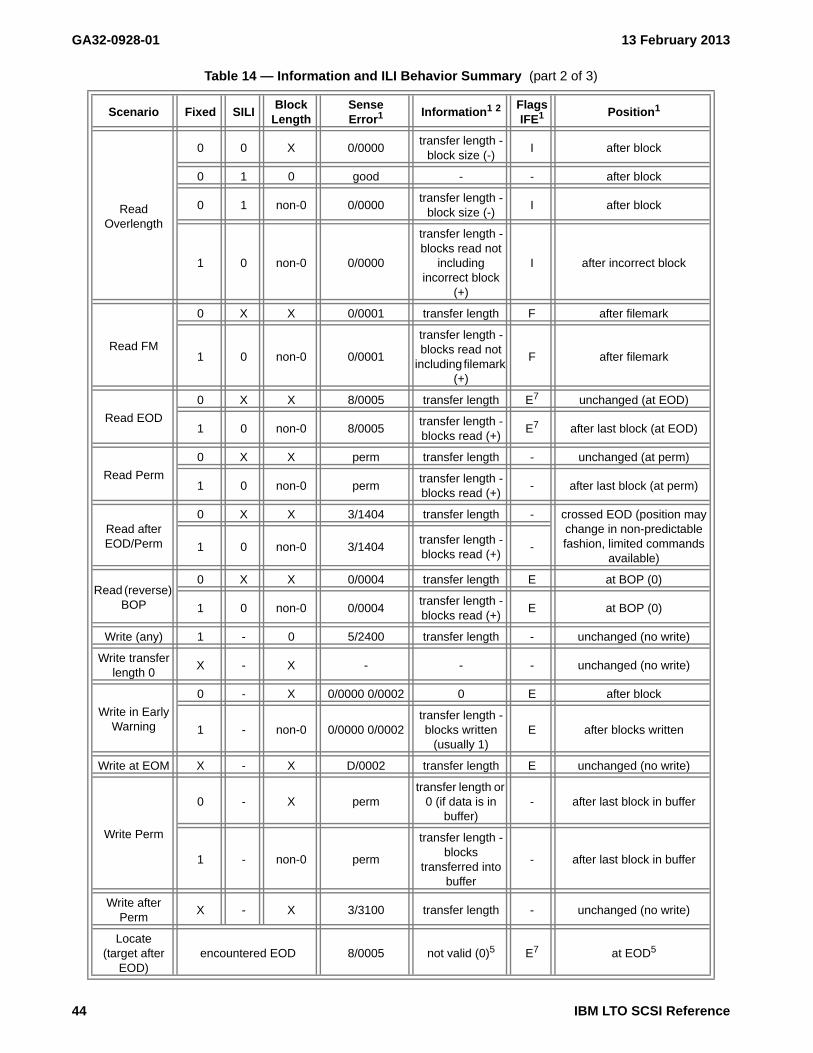
GA32-0928-01 13 February 2013
ReadOverlength
0 0 X 0/0000 transfer length -
block size (-) I after block
0 1 0 good - - after block
0 1 non-0 0/0000 transfer length -
block size (-) I after block
1 0 non-0 0/0000
transfer length - blocks read not
including incorrect block
(+)
I after incorrect block
Read FM
0 X X 0/0001 transfer length F after filemark
1 0 non-0 0/0001
transfer length - blocks read not
including filemark (+)
F after filemark
Read EOD
0 X X 8/0005 transfer length E7 unchanged (at EOD)
1 0 non-0 8/0005 transfer length - blocks read (+)
E7 after last block (at EOD)
Read Perm
0 X X perm transfer length - unchanged (at perm)
1 0 non-0 perm transfer length - blocks read (+)
- after last block (at perm)
Read after EOD/Perm
0 X X 3/1404 transfer length - crossed EOD (position may change in non-predictable fashion, limited commands
available) 1 0 non-0 3/1404
transfer length - blocks read (+)
-
Read (reverse) BOP
0 X X 0/0004 transfer length E at BOP (0)
1 0 non-0 0/0004 transfer length - blocks read (+)
E at BOP (0)
Write (any) 1 - 0 5/2400 transfer length - unchanged (no write)
Write transfer length 0
X - X - - - unchanged (no write)
Write in Early Warning
0 - X 0/0000 0/0002 0 E after block
1 - non-0 0/0000 0/0002 transfer length - blocks written
(usually 1) E after blocks written
Write at EOM X - X D/0002 transfer length E unchanged (no write)
Write Perm
0 - X perm transfer length or
0 (if data is in buffer)
- after last block in buffer
1 - non-0 perm
transfer length - blocks
transferred into buffer
- after last block in buffer
Write after Perm
X - X 3/3100 transfer length - unchanged (no write)
Locate(target after
EOD) encountered EOD 8/0005 not valid (0)5 E7 at EOD5
Table 14 — Information and ILI Behavior Summary (part 2 of 3)
Scenario Fixed SILI Block
Length SenseError1
Information1 2 FlagsIFE1
Position1
44 IBM LTO SCSI Reference

13 February 2013 GA32-0928-01
Locate encountered Perm perm not valid (0)5 - indeterminate (unchanged or
at perm)5
Spaceblocks
encountered FM 0/0001
Count - blocks traversed3
F after FM
encountered EOD 8/0005 E6 at EOD
encountered BOP 0/0004 E at BOP (0)
encountered perm perm - indeterminate (unchanged or
at perm)3
Spacefilemarks
encountered EOD 8/0005
Count - FMs traversed4
E6 at EOD4
encountered BOP 0/0004 E at BOP (0)
encountered perm perm - indeterminate (unchanged or
at perm)4
Space sequential filemarks
encountered EOD 8/0005 Count - sequential FMs
traversed immediately prior
to ending position5
E6 at EOD5
encountered BOP 0/0004 E at BOP (0)
encountered perm perm - indeterminate (unchanged or
at perm)5
SpaceEOD
encountered EOD good -5 - at EOD5
encountered perm perm not valid (0)5 - indeterminate (unchanged or
at perm)5
Legend:Flags:
I ILI bit #/#### CC, sense of Sense Key/ASC ASCQE EOM bit perm CC, sense as per permF Filemark bit good No CC (no sense)
- None set - Not applicable
Notes: 1 These fields are outputs (results) from the scenario operation. 2 Partial blocks are not considered read, written or traversed. 3 Information field will accurately reflect the ending position. 4 Information field will accurately reflect the ending position but it is not in units of logical blocks, so additional
means of determining absolute location, such as Read Position, must be used. 5 Information field does not accurately reflect the ending position, another means of determining absolute
location, such as Read Position, must be used. 6 The EOM bit may be set only if the current position is in the early warning region or if the end of partition is
encountered. 7 The EOM bit will only be set if end of partition is encountered (this condition should never occur), so EOM
should not be set in this case. The standard specifies that EOM bit shall be set only if the current position is in the early warning region or if the end of partition is encountered.
Table 14 — Information and ILI Behavior Summary (part 3 of 3)
Scenario Fixed SILI Block
Length SenseError1
Information1 2 FlagsIFE1
Position1
IBM LTO SCSI Reference 45

GA32-0928-01 13 February 2013
4.9 Cleaning the Drive in a Library
In a library, the drive may be automatically cleaned. If the library configures the drive for automatic cleaning, then the drive behaves as follows:
When the drive determines that either maintenance cleaning is required, or that the SARS thresholds have been reached, a message is sent to the library (via the Library/Drive interface) to request cleaning. This occurs when the Cleaning message is normally sent to the SCD (Single Character Display). The library schedules the mounting of the cleaning cartridge. Thus, the host operating system and application are freed of any responsibility to facilitate the cleaning.
46 IBM LTO SCSI Reference

13 February 2013 GA32-0928-01
4.10 Drive Cleaning Indicators
For stand-alone drive models, automatic cleaning of the drive is not possible. For library models, automatic cleaning of the drives by the library may be disabled (although it is not recommended). For either case, cleaning of the drives must be managed by the host application or manually, by the operator.
NOTE 5 - Failure to clean a drive may result in data loss.
This section describes how cleaning indicators are presented from the drive. The cleaning indicators may be presented even with automatic cleaning enabled in a library environment. The cleaning indicators can be presented through the following:
a) Panel Cleaning Indication (see 4.10.1)b) Host Interface - Dynamic Cleaning Indicators (see 4.10.2)c) Host Interface - Static Cleaning Indicator (Sense Data Byte 70) (see 4.10.3)
4.10.1 Panel Cleaning Indication
A CLEAN message is displayed on the SCD (Single Character Display) when cleaning with a cleaning cartridge is required. For additional details, see the Operator Guide for this product.
4.10.2 Host Interface - Dynamic Cleaning Indicators
Dynamic cleaning indicators that are sent across the host interface include:
a) ASC/ASCQ codes related to cleaning in Error Sense Information (see Annex B. on page 481). Cleaning Indicators reported with Sense Key 1 may only be reported in certain situations, see MP 01h: Read-Write Error Recovery (see 6.6.5 on page 367).
b) TapeAlert codes related to cleaning as described in LP 2Eh: TapeAlerts (see 6.4.16 on page 316).
NOTE 6 - If the device driver shields the application from dynamic notifications, the information is usually available from the system error log.
4.10.3 Host Interface - Static Cleaning Indicator (Sense Data Byte 70)
The bit significance of sense data byte 21 follows:
Bit Description3 Set to 1b "Cleaning Required: Normal Maintenance” when cleaning is required because of the
normal preventive maintenance guideline (See “MP 2Fh: Behavior Configuration” on page 403.).
Reset to 0b when the cleaning cartridge is loaded.
Table 15 — ASC/ASCQ Codes Related to Cleaning
Code Description Sense Key ASC ASCQ
Drive Requires Cleaning 0 82 82
Cleaning in Progress (cleaner cartridge) 2 30 03
IBM LTO SCSI Reference 47

GA32-0928-01 13 February 2013
4.11 WORM Behaviors
4.11.1 Conditions for Writing
If the following condition is met, writing is allowed:
c) the cartridge is uninitialized
If all the following conditions are met, writing is allowed:
a) the current logical position is at BOPb) there are only filemarks between here and EOD
If all of the following conditions are met, writing is allowed:
a) if the current logical position is at BOPb) there are exactly 1 or 2 data records, followed by 0 to infinite number of filemarks, followed by no data
records, followed by EOD
If all of the following conditions are met, writing is allowed:
a) the current logical position is between BOP and EOD:b) there are only filemarks from the current logical position to EODc) there is at least one filemark immediately before the current logical position
If the following condition is met, writing is allowed:
a) the current logical position is AT EOD
4.11.2 Command Behavior When WORM Medium Has Been Tampered With
Table 379 specifies the behavior of the device when it has detected the WORM medium that is loaded in the drive has been tampered with (See “MP 10h: Device Configuration” on page 377.).
Table 16 — Behavior when the loaded medium has suspect integrity
Command WTRE=01b WTRE=00b or 10b
WRITE 7/300Dh 7/300Dh
WRITE FILEMARK n (n !=0) 7/300Dh 7/300Dh
WRITE FILEMARK 0 (buffered data) 7/300Dh 7/300Dh
WRITE FILEMARK 0 (no buffered data) GOOD GOOD
ERASE 7/300Dh 7/300Dh
READ GOOD 3/300Dh
VERIFY GOOD 3/300Dh
SPACE GOOD 3/300Dh
LOCATE to (block !=0) GOOD 3/300Dh
LOCATE to 0 GOOD GOOD
REWIND GOOD GOOD
UNLOAD GOOD GOOD
LOAD GOOD GOOD
48 IBM LTO SCSI Reference

13 February 2013 GA32-0928-01
4.12 Device Hardware Encryption
This device contains hardware which performs user data write encryption and read decryption, protecting all user data written to the medium from unauthorized use [provided it is integrated into a secure system design]. Device support for encryption may be determined by reading MP 24h: Vendor-Specific (see 6.6.19 on page 398) with the MODE SENSE command.
This device supports multiple ways of controlling encryption settings. These encryption control methodologies are called:
a) Encryption Control - IBM Proprietary Protocol (IPP) (see 4.12.1 on page 49); andb) Encryption Control - T10 Standards (see 4.12.2 on page 49).
On volumes with multiple partitions, the drive handles encryption in each partition as determined when a writeoccurs at BOP:
a) If logical block 0 in a partition is encrypted using IBM proprietary methods (see 4.12.1), then all blockswithin the partition are enforced to be encrypted;
b) If logical block 0 in a partition is not encrypted, then all blocks in the partition are not enforced to beencrypted; and
c) if the encryption method in the drive is set to AME-T10 (see 4.12.2), then an intermix of encrypted andunencrypted blocks are allowed.
4.12.1 Encryption Control - IBM Proprietary Protocol (IPP)
The following terms are used to describe the methods of control that fall into the IPP:
a) Library Managed Encryption (LME);b) System Managed Encryption (SME); andc) Application Managed Encryption - IBM (AME-IBM).
When a device is enabled to perform encryption using one of the IBM Proprietary Protocols (i.e., LME, SME, orAME-IBM) encryption parameters are determined at first write from BOP. On volumes with multiple partitions thismeans that on a write from BOP(i.e. LBA 0) of each partition the encryption parameters are determined. Writesaway from BOP use the existing encryption parameters. If a logical block is encrypted, then all logical blocks areencrypted. If a logical block is not encrypted then all logical blocks are not encrypted. When a partition changeoccurs the encryption parameters are cleared.
Please see IBM for additional information on IPP.
4.12.2 Encryption Control - T10 Standards
The T10 standards method of controlling encryption are described in SSC-3 as well as in this document. Note that not all methods described in SSC-3 are supported.
This device uses the term Application Managed Encryption - T10 (AME-T10) to signify that it is using this standards based method.
This device supports the T10 method of passing the key in clear text as well as using ESP-SCSI. For specifics on support refer to SECURITY PROTOCOL IN (SPIN) - A2h (see 5.2.30 on page 161), SECURITY PROTOCOL OUT (SPOUT) - B5h (see 5.2.31 on page 162), and Security Protocol Parameters (SPP) (see 6.8 on page 433).
IBM LTO SCSI Reference 49

GA32-0928-01 13 February 2013
4.13 Attachment Features
4.13.1 Types of Interface Attachments
This device communicates with servers that use Fibre Channel or SAS interfaces. The interfaces share certain tape LUN behaviors, but also possess unique features. This chapter describes the common and unique features of these interfaces.
4.13.2 Common Tape LUN Behaviors
Fibre Channel and SAS attached devices share the following tape LUN behaviors:
a) Power-On (see 4.13.2.1 on page 50);b) Reset Strategy (see 4.13.2.2 on page 50);c) Abort Handling (see 4.13.2.3 on page 50);d) Multi-initiator Support (see 4.13.2.4 on page 52); ande) Status Codes (see 4.13.2.5 on page 53).
4.13.2.1 Power-On
The drive responds to INQUIRY, REPORT LUNs, REQUEST SENSE, and TEST UNIT READY commands within 5 seconds of power-on. The first command (other than INQUIRY or REQUEST SENSE) from any initiator gets a CHECK CONDITION status with UNIT ATTENTION sense data for the power-on. After this, any medium access command is reported with a Sense Key of NOT READY and an additional sense code of LUN HAS NOT SELF-CONFIGURED YET (3E00). Once the drive has completed its self test and setup procedures, the drive attempts to load any tape that is present. Medium access commands are reported with an additional sense code of DRIVE IN PROCESS OF BECOMING READY (0401).
4.13.2.2 Reset Strategy
The drive supports the hard reset option as is required by SCSI-3. On receiving a reset, the following actions are taken:
f) The current I/O process is aborted, as in Abort Handling.g) Any queued I/O processes from other initiators are removed.h) All SPC-2 reservations are cleared, but Persistent Reservations remain in effect.i) All mode values are reset to their defaults.j) A unit attention condition is set.k) A logical position is established that may or may not be the same as the position prior to the reset.
Where possible, the logical position prior to reset is maintained.l) The next command that is eligible for the UNIT ATTENTION CHECK CONDITION from each initiator
gets a CHECK CONDITION STATUS, with UNIT ATTENTION sense data for the reset. However, other commands may not be processed until the internal state of the drive has been reset.
4.13.2.3 Abort Handling
Table 17 specifies the abort processing for this device.
50 IBM LTO SCSI Reference

13 February 2013 GA32-0928-01
Table 17 — Abort Condition Handling (part 1 of 2)
Command Abort Processing
ALLOW OVERWRITE The Command completes
ERASELong erase is aborted as quickly as possible without corrupting tape format. Short erase completes.
FORMATIf modification to medium has started then the command is completed; otherwise, no action is taken.
INQUIRY None.
LOAD/UNLOADLoad completes and logically positions tape at BOP 0. Unload is aborted, leaving logical position at BOP 0 unless operation is past the ‘point of no return’, in which case the tape is ejected.
LOCATEThe logical position is set back to that at the start of the operation unless the operation is past its ‘point of no return’, in which case the operation completes.
LOG SELECTIf data transfer is completed, command is completed; otherwise, no action is taken.
LOG SENSE None.
MODE SELECTIf data transfer is completed, command is completed; otherwise, no action is taken.
MODE SENSE None.
PERSISTENT RESERVE IN None.
PERSISTENT RESERVE OUTIf data transfer is completed, the command is completed; otherwise, no action is taken.
PREVENT ALLOW MEDIUM REMOVAL
The command completes.
READThe current position is set to the first record boundary at or after the start of the current data burst.
READ ATTRIBUTE None.
READ BLOCK LIMITS None.
READ BUFFER None.
READ POSITION None.
RECEIVE DIAGNOSTIC RESULTS None.
RELEASE UNIT The command completes.
REPORT DENSITY SUPPORT None.
REPORT LUNs None.
REPORT SUPPORTED OPERATION CODE
None.
REPORT SUPPORTED TASK MANAGEMENT FUNCTIONS
None.
REQUEST SENSE Sense data is discarded.
RESERVE UNIT The command completes.
REWIND The command completes.
SECURITY PROTOCOL IN None.
SECURITY PROTOCOL OUTIf data transfer is completed, the command is completed; otherwise, no action is taken.
SEND DIAGNOSTIC Vendor unique.
IBM LTO SCSI Reference 51

GA32-0928-01 13 February 2013
An INQUIRY command returns the required data and gives GOOD status. A REQUEST SENSE command gives No Sense. A TEST UNIT READY command reports with status immediately.
4.13.2.4 Multi-initiator Support
This device supports an infinite number of I_T nexuses, but the device has a limit on how many I_T nexuses can be logged in processing commands concurrently. If this limit is exceeded, then the device implicitly logs out the least recently used (LRU) I_T nexus that:
a) is not reserved;b) is not registered;c) is not the I_T nexus that last processed a medium access command; andd) does not have an outstanding command.
The device supports untagged queuing when operating with multiple initiators. If a command from one initiator is being processed when a command other than INQUIRY, REPORT LUNs, REQUEST SENSE, and TEST UNIT READY is received from a second initiator, the new command is queued. Media access commands (for example, WRITE, WRITE FILEMARKS, READ, VERIFY, REWIND, MODE SELECT that changes block size) are always processed in strict order of receipt.
The INQUIRY, REPORT LUNS, REQUEST SENSE, and TEST UNIT READY commands are always processed immediately, irrespective of whether a command from another initiator is being processed.
The drive maintains sense data for the supported number of initiators. If an additional initiator connects to the drive and causes an initiator to be implicitly logged out, the drive erases all sense data for that initiator before processing the command for the new initiator. See Sense Data Management for more details of sense data management.
SET CAPACITYIf modification to medium has started then the command is completed; otherwise, no action is taken.
SPACEThe logical position is set back to that at the start of the operation unless the operation is past its ‘point of no return’, in which case the operation completes.
TEST UNIT READY None.
VERIFYThe logical position is set to the next record boundary after the point where the verify was aborted.
WRITE
The data up to first record boundary in the current burst is written to buffer or tape, depending on Buffered Mode. Any subsequent data is discarded. If there is no record boundary in the current burst, the record is truncated to the amount of data transferred and written to buffer or tape, again depending on Buffered Mode.
WRITE ATTRIBUTEIf data transfer is completed, the command is completed; otherwise, no action is taken.
WRITE BUFFERIf data transfer is completed, the command is completed; otherwise, no action is taken.
WRITE FILE MARKS The command completes.
Table 17 — Abort Condition Handling (part 2 of 2)
Command Abort Processing
52 IBM LTO SCSI Reference

13 February 2013 GA32-0928-01
4.13.2.5 Status Codes
4.13.3 Features of the Fibre Channel Interface
This device is compliant with the American National Standard, Project T10/Project 1828-D, Information Technology - Fibre Channel Protocol for SCSI, Fourth Version (FCP-4), Revision 02b, January 3, 2011. The key features of the FC-Tape Technical Report of the Accredited Standard Committee NCITS that were found useful are included in FCP-4. IBM recommends that a server’s device driver and host bus adapter (HBA) use:
a) Precise delivery of commands;b) Confirmed completion of FCP I/O operations;c) Retransmission of unsuccessfully transmitted IUs; andd) Task retry identification as defined in FCP-4.
These features may be listed in HBA settings either individually or as a group and called:
a) FCP-2 support;b) Class-3 Error Recovery;c) FC-Tape;d) Confirmed Completion; ore) Task retry identification.
The World Wide Node Name and Port Name that are used by the device follow the format of the Institute of Electrical and Electronics Engineers (IEEE).
4.13.3.1 Topology
Fibre Channel devices (such as this device and a server) are known as nodes and have at least one port through which to receive and send data. The collection of components that connect two or more nodes is called a topology. Fibre Channel systems consist solely of two components: nodes with ports and topologies.
Each port uses a pair of fibers: one fiber carries data into the port, and the other carries data out of the port. The fibers in the channel are optical strands. The fiber pair is called a link and is part of the topology. Data is transmitted over the links in units known as frames. A frame contains an address identifier that gives the fabric and node for which the frame is destined.
This device can be attached in a two-node configuration, either directly to a switch as a public device (switched fabric) or directly to a host bus adapter (HBA) as a private device (direct connection). This device may be configued to any supported topology via a library interface, or configured by using vital product data (VPD) settings. The type of connection also depends on whether the drive recognizes the connection as a loop or a fabric connection:
a) An L_port supports a Fibre Channel Arbitrated Loop connection to an L_port or FL_port.
Table 18 — Status Codes
Status Code Value Circumstance
GOOD 00h The command completed without problems.
CHECK CONDITION 02hA problem occurred during command processing. The sense data should be examined to determine the nature of the problem.
BUSY 08hThe drive is unable to accept the command at this time. This status is returned during the power-on sequence or if there are commands from too many I_T nexuses outstanding. (See Multi-initiator Support.)
RESERVATION CONFLICT 18hThis status is returned if the drive is reserved for an I_T nexus other than the one sending the command.
QUEUE FULL 28h Not normally returned.
IBM LTO SCSI Reference 53

GA32-0928-01 13 February 2013
b) An N_port supports direct connection to an F_port (for example, a director-class switch) in a fabric topology.
Regardless of the port to which this device is connected, it automatically configures to a public device (through an F_port or FL_port to a switch) or to a private device (through an L_port by using direct attachment to a server). This device supports two topologies:
a) Two-Node Switched Fabric Topology (see 4.13.3.1.1 on page 54); andb) Two-Node Direct Connection Topology (see 4.13.3.1.2 on page 54).
Table 19 lists the topologies in which this device is able to operate, the Fibre Channel server connections that are available, and the port (NL, N, FL, or F) through which communication must occur. The sections that follow describe each topology.
4.13.3.1.1 Two-Node Switched Fabric Topology
The two-node switched fabric topology supports two protocols:
a) Use the two-node switched fabric loop protocol when attaching the device to an FL_port; andb) Use the two-node switched fabric protocol when attaching the library to an F_port.
4.13.3.1.2 Two-Node Direct Connection Topology
A two-node direct connection occurs when two Fibre Channel end points are connected together. Either Arbitrated Loop or Point-to-Point topology is defined as usable in the standards, but both end points must use the same topology. Most Fibre Channel adapters have settings that allow selection of the topology or they default to the loop topology when they are not directly connected to a fabric. While this device allows you to set the port to any of these topologies (see the instructions of the library in which this device is contained) this device requires the use of the Arbitrated Loop (L_port) topology in a two-node direct connection. Use of the Point-to-Point topology in a two-node direct connection to an N_port is not supported.
4.13.3.2 Speed
This device is an 8GFC device meaning that it can operate at 8.500 MBd. This device also allows operation using previous Fibre Channel generations: 1GFC, 2GFC, and 4GFC. Each Fibre Channel generation transfers data at the following rates:
a) 1GFC transfers data at a max burst rate of 100 MB/s;b) 2GFC transfers data at a max burst rate of 200 MB/s;
Table 19 — Topologies through which this device’s port(s) can operate
Drive Port Configuration
Type of Fibre Channel Port to Which the Drive Port Connects
Server Port (HBA)(Private - Direct Connection)
Switch Port(Public - Switched Fabric)
Point-to-PointTopology(N_Port)
Arbitrated Loop Topology (FC-AL) FabricTopology(F_Port)L_Port FL_Port
Drive port configured to operate as L_PortInvalid systemconfiguration
L_Port L_PortInvalid systemconfiguration
Drive port configured to operate as N_PortN_Port
(not supported)Invalid systemconfiguration
N_Port(switched fabric)
N_Port
Drive port configured to operate as LN_PortN_Port
(not supported;attempts L_Port)
L_Port L_Port N_Port
Drive port configured to operate as NL_PortN_Port
(not supported;attempts L_Port)
L_Port N_Port N_Port
54 IBM LTO SCSI Reference

13 February 2013 GA32-0928-01
c) 4GFC transfers data at a max burst rate of 400 MB/s;d) 5GFC transfers data at a max burst rate of 800 MB/s;
This device may be configured via a library interface or vital product data (VPD) in one of the following speed configurations:
a) 1GFC;b) 2GFC;c) 4GFC;d) 8GFC; ore) speed negotiate
4.13.3.3 Addressing Assignments
Each Fibre Channel interface port for this device can be independently assigned a specific speed and topology, or may be set to auto-negotiate.
When the topology is set to or negotiates to L-port, a hard or soft ALPA ID may be assigned. The hard ALPA ID is in the range of 01h to EFh with only certain valid values (a total of 126 addresses). Validity is enforced by the entry process. This value should be unique to each device on the Fibre Channel loop. Fibre Channel loop protocol will detect an addressing conflict on the loop, and one of the conflicting drives will not be available for use.
4.13.4 Features of the Serial Attached SCSI (SAS) Interface
The World Wide Node Name and Port Name that are used by this device follow the format of the Institute of Electrical and Electronics Engineers (IEEE).
This device is compliant with the American National Standard, Project T10/1760-D, Information technology - Serial Attached SCSI - 2 (SAS-2), Revision 16, 18 April 2009.
IBM LTO SCSI Reference 55

GA32-0928-01 13 February 2013
4.14 Device Clocks
The drive supports a Device Clock that maintains a timestamp for various items. This timestamp gets recorded in drive error logs.
The TIMESTAMP ORIGIN is one of those specified in table 20.
Once a timestamp is initialized it begins counting from that time forward. Once the timestamp is initialized it remains in effect until one of the following occurs:
a) A SET TIMESTAMP command (see 5.2.34) is processed;b) An LDI command is processed that modifies the timestamp; orc) A Hard Reset event occurs.
The method used is indicated in the Extended Control mode page.
The Timestamp is not affected by an I_T nexus loss or a Logical Unit reset.
The TIMESTAMP is specified in table 21.
The TIMESTAMP field contains the value established at the last action that set the timestamp incremented by one for every millisecond that has elapsed since the timestamp was set.
Table 20 — TIMESTAMP ORIGIN
Value Definition
000b Timestamp initialized to zero at power-on
001b Reserved
010b Timestamp initialized by the SET TIMESTAMP command
011b Timestamp initialized by the Library over the Library Drive Interface (i.e. RS-422)
100b - 111b Reserved
Table 21 — TIMESTAMP Format
ByteBit
7 6 5 4 3 2 1 0
0 (MSB)TIMESTAMP
5 (LSB)
56 IBM LTO SCSI Reference

13 February 2013 GA32-0928-01
4.15 Dynamic runtime information
4.15.1 Dynamic runtime information overview
Dynamic runtime information allows an initiator to set dynamic runtime attributes (DRA) about itself into a device server. The device server then associates those attributes to the I_T_L nexus and uses the information and associations for enhanced data collection and debugging. This information and the associations are added to device error logs (e.g., drive dump) and are provided for retrieval by an application client through the READ DYNAMIC RUNTIME ATTRIBUTE command (see 5.2.18).
The Ultrium 5 and later devices support dynamic runtime attributes with the READ DYNAMIC RUNTIME ATTRIBUTE command (see 5.2.18) and the WRITE DYNAMIC RUNTIME ATTRIBUTE command (see 5.2.42). These commands are used to retrieve and store information in the form of dynamic runtime attributes.
A DRA is represented in a format described in 6.1.1 and is composed of:
a) an I_T nexus index;b) an attribute identifier;c) an attribute format code;d) a bit indicating whether the identified attribute is read only;e) an attribute length specifying the number of bytes in the identified attribute value; andf) the value of the identified attribute.
There are three types of DRA attributes (see table 22).
DRA attributes have the states shown in table 23.
Table 22 — Types of DRA attributes
AttributeType
Focus Attribute Source
Readablewith READDYNAMICRUNTIME
ATTRIBUTE
Writablewith WRITEDYNAMICRUNTIME
ATTRIBUTE
Reference
Logical unit Device Set by the device server. Yes No 6.1.2.2
Target I_T nexus Set by the device server. Yes No 6.1.2.3
Initiator I_T nexus Set by the application client Yes Yes 6.1.2.4
Table 23 — DRA attribute states
Attribute State Description
Read Only
An application client may read the contents of the DRA attribute with the READ DYNAMIC RUNTIME ATTRIBUTE command, but an attempt to clear or change the DRA attribute using the WRITE DYNAMIC RUNTIME ATTRIBUTE command shall result in the command being terminated with CHECK CONDITION status with the sense key set to DATA PROTECT and the additional sense code set to WRITE PROTECTED. When in the read only state the READ ONLY bit (see 6.1.1) is one.
UnsupportedThe device server does not support the DRA attribute and shall not return it in response to a READ DYNAMIC RUNTIME ATTRIBUTE command.
NonexistentAn initiator attribute does not exist in the dynamic runtime attributes until a WRITE DYNAMIC RUNTIME ATTRIBUTE command creates it.
Read/Write
The DRA attribute has been created using the WRITE DYNAMIC RUNTIME ATTRIBUTE command. After the DRA attribute has been created, the contents may be altered using subsequent WRITE DYNAMIC RUNTIME ATTRIBUTE commands. A Read/Write DRA attribute may be returned to the nonexistent state using a WRITE DYNAMIC RUNTIME ATTRIBUTE command with the attribute length set to zero. When in the Read/Write state the READ ONLY bit (see 6.1.1) is zero.
IBM LTO SCSI Reference 57

GA32-0928-01 13 February 2013
4.15.2 Dynamic runtime information timestamp
Some dynamic runtime attributes have a timestamp associated with them. The timestamp used is described in Device Clocks (see 4.14 on page 56). If no timestamp is set by either a SCSI command (i.e., SET TIMESTAMP or ) or by the library, then the timestamp will be power-on time and may not be able to be correlated to external logs (e.g., device driver logs, application logs).
4.15.3 Setting dynamic runtime information into the drive
An application client may set attributes into the drive using the WRITE DYNAMIC RUNTIME ATTRIBUTE command (see 5.2.42) to set one or more of the initiator type attributes defined in 6.1.2.4. The application client may write these values at any time and may change these values at any time. If an application client attempts to create a new attribute by writing an attribute that was previously in the non-existent state and the device server does not have the resources necessary to create that attribute the device server shall reject the command with a CHECK CONDITION with the sense code set to ILLEGAL REQUEST and the additional sense code set to INSUFFICIENT RESOURCES (i.e., 5h / 5503h).
4.15.4 Retrieving dynamic runtime information from the drive
An application client may read attributes by using the READ DYNAMIC RUNTIME ATTRIBUTE command (see 5.2.18). The application client may request a single attribute or multiple attributes in a single command. The application client may read any existent attribute (see 6.1).
4.15.5 Management of dynamic runtime information
Dynamic runtime attributes have either a focus of a logical unit (i.e., logical unit type attributes) or a focus of I_T nexus (i.e., target type attributes and initiator type attributes). This relationship is shown in figure 8.
Figure 8 — Dynamic runtime attributes focus
Logical Unit Attributes
I_T nexus
Target Attributes
Initiator Attributes
I_T nexus
Target Attributes
Initiator Attributes
I_T nexus
Target Attributes
Initiator Attributes
58 IBM LTO SCSI Reference

13 February 2013 GA32-0928-01
For each dynamic runtime attribute (see 6.1) that the device server supports, if a command is received that should cause an update of one or more of the dynamic runtime attributes (e.g., Reserve, Persistent Reserve Out, Prevent/Allow Medium Removal), then the device server shall update that dynamic runtime attribute. If one or more of the Initiator type attributes that are supposed to be used to update the dynamic runtime attribute is in the nonexistent state, then all information that is known is used. The TransportID of the I_T_L nexus and the target port identifier of the I_T_L nexus is always known from the transport layer and are presented as target type attributes.
4.15.5.1 Dynamic Runtime Information Lifetime
Dynamic Runtime Attributes are maintained separate from the device server’s management of I_T nexuses. The I_T_L nexus identifying information (see 6.1.2.2.1) remains in existence inside dynamic runtime attributes even after the I_T nexus referenced is no longer known by the SCSI target port.
Logical unit type attributes (see 6.1.2.2) are created if an event occurs as described in the description of each logical unit type attribute and are destroyed if an event occurs as described in the description of each specific logical unit type attribute.
Target type attributes (see 6.1.2.3) are created by the drive if it detects communication from a new I_T nexus (e.g., Fibre Channel PLOGI/PRLI sequence) and are destroyed by the drive if it detects the disappearance of the I_T nexus (e.g., Fibre Channel LOGO, I_T nexus resources are released to allow a new I_T nexus to communicate with the drive).
Initiator type attributes (see 6.1.2.4) are created if a WRITE DYNAMIC RUNTIME ATTRIBUTE command is received requesting a new attribute and are destroyed if the drive detects the destruction of the target type attribute associated with the I_T nexus that created the Initiator type attribute.
Dynamic Runtime Attributes do not persist across a device power off.
IBM LTO SCSI Reference 59

GA32-0928-01 13 February 2013
4.16 Error Information
4.16.1 Sense Data
For a description of Sense data, see Sense Data Format.
4.16.2 Sense Data Management
Sense data returned by the device contains one of two types of errors. These errors are:
Type DescriptionCurrent The error condition associated with the command that is currently being processed (i.e.,
SCSI Status for the currently processing command is the status being returned); andDeferred The error condition resulting from a command that has been reported as GOOD, but has
generated sense data after being reported. This may be a command with the Immediate bit set or may be a buffered write.
Sense data returned is described by the Sense Key (i.e., bits 3-0 of byte 2 of Sense data). Commands that terminate in an error generate Sense data and set the Sense Key depending on the the specifics of the error. Table 8. Supported Common SCSI commands, indicates which commands are allowed to be processed in the presence of specific error conditions and which return an error.
This device communicates on transports that use the autosense protocol. This means that any Sense data generated for return to a command is returned with the SCSI status. Once a particular set of sense data has been returned, that sense data is cleared and a REQUEST SENSE command is not required to be issued to collect the Sense data. Any other sense data that is still pending may still cause CHECK CONDITION status for subsequent commands. When a REQUEST SENSE command is received, typically the only Sense data available will be the default Sense data. While it is possible that a Deferred error may have generated Sense data or that a Unit Attention (see 4.16.4) has been established since the status to the last command, Sense data is not likely to exist.
4.16.3 Deferred Check Condition (DCC)
Deferred errors are generated by processing that occurs when that process is not attached to the currently processing command (see 4.16.2). Deferred errors are reported as sense data to a deferred check condition (DCC) eligible command (i.e., DCC column of table 27 on page 70 is set to ‘Y’).
In the case of a deferred write error if buffered mode 1h is selected and a DCC eligible command is received, then the error is reported to the SCSI initiator device (i.e., I_T nexus) that has deferred error affinity.
If the drive receives a deferred error affinity command (i.e., DEA column of table 27 on page 70 is set to ‘Y’), then the drive performs actions in the following order:
1) performs initial checking (e.g., Reservation Conflict, all pending Unit Attentions, and all pending errors to be reported to this I_T nexus) and reports these conditions, if any;
2) if none of the above conditions are reported, then all pending deferred errors are migrated to the I_T nexus through which this command was received;
3) the deferred error affinity is set to this I_T nexus;4) if the command is DCC eligible, then pending deferred errors, if any, are reported; and5) if no deferred errors were reported process the command.
4.16.4 Unit Attention Conditions
The drive generates a Unit Attention condition under the following circumstances:
a) Reset condition (for example, power-on, SCSI reset, bus device reset);b) Tape Loaded condition (for example, media inserted, LOAD command from another initiator);c) Mode parameters changed by another initiator; andd) Drive firmware has been upgraded.
60 IBM LTO SCSI Reference

13 February 2013 GA32-0928-01
The drive only maintains one instance of each type of Unit Attention condition at any one time for any one initiator. If a subsequent Unit Attention condition of the same type is generated, it replaces the existing one. Unit Attentions are returned in priority order. The priorities are in the order listed above, with a reset being highest priority and a firmware upgrade being lowest priority.
4.16.5 Persistent Errors
When errors occur that prevent tape operation, they are reported persistently until the problem is cleared. For medium-related errors (usually reported with a Sense Key of 3), the error is reported until the cartridge is successfully unloaded. For hardware-related errors (usually reported with a Sense Key of 4), the error is reported until the drive successfully performs a power-on self test. These persistent errors are only reported on those commands that are eligible for deferred Check Condition reporting (see Table 4). The error may or may not be reported as Deferred.
4.16.5.1 Fencing Behavior
The device fences the drive (i.e., prevents certain operations) when errors are detected that could endanger customer data if further usage is allowed. The operations that are prevented depend on the nature of the error encountered and the current drive state. The drive will post an FSC (see bytes 16 and 17 of REQUEST SENSE data) for the original error that caused the fence condition. Then, CHECK CONDITION status, with the fencing FSC in the sense data is reported to an attempted host commands that is not allowed due to the fence condition.
Table 24 lists which errors trigger which fence state.
4.16.5.1.1 ALLOW_NO_OPERATION
a) All medium access commands (Read/Write/Motion) are rejected.b) (SCSI/Panel/LDI) Unload is accepted.c) After the cartridge is ejected:
A) When load is attempted, the cartridge stays at mount position and Good status is returned for TUR.B) From the above state, the cartridge can be ejected normally.C) Other medium access commands are rejected.
4.16.5.1.2 ALLOW_LOCATE
a) All medium access commands (Read/Write/Motion) are rejected.b) (SCSI/Panel/LDI) Unload is accepted.
Table 24 — Error to Fence State mapping
Error that triggers Fence State Fence State
Severe Drive Hardware problemSevere Media Hardware problemTemperature OverrangeLoad or Unload Hardware problemSevere Firmware Problem
ALLOW_NO_OPERATION (see 4.16.5.1.1 on page 61)
Hardware Problem detected that could affect WritingHardware Problem detected that could affect Reading
ALLOW_LOCATE (see 4.16.5.1.2 on page 61)
Serious Drive Hardware problem -- May be recovered on a different mountSerious Media problem -- Drive may be recovered on different mountSerious Firmware problem -- May be recovered on different mount
ALLOW_UNLOAD (see 4.16.5.1.3 on page 62)
Power on occurs and the device detects a volume is loaded. This may be due to a device panic/exception.
MID-TAPE RECOVERY (see 4.16.5.1.4 on page 62)
IBM LTO SCSI Reference 61

GA32-0928-01 13 February 2013
c) Once a cartridge is ejected, Fence state is cleared. You can load a new cartridge and perform all medium access commands.
d) Space command is rejected while in Fence state.
4.16.5.1.3 ALLOW_UNLOAD
a) All medium access commands (Read/Write/Motion) are rejected.b) (SCSI/Panel/LDI) Unload is accepted.c) Once a cartridge is ejected, Fence state is cleared. You can load a new cartridge and perform all medium
access commands.
4.16.5.1.4 MID-TAPE RECOVERY
The Mid-Tape Recovery (MTR) fence behavior is configured in Mode Page 2Fh: Behavior Configuration Mode Page. There are two different behaviors:
a) Normal operation (i.e., MTR Fence) (see 4.16.5.1.4.1 on page 62); andb) Panic Fence operation (see 4.16.5.1.4.2 on page 62).
4.16.5.1.4.1 Normal operation (i.e., MTR Fence)
When the device powers up and no cartridge is detected, no special behavior is required and the device:
1) responds to the first UNIT ATTENTION eligible command with 6/2900;2) responds to a CHECK CONDITION eligible command, if any, with 2/3e00 during POST; and3) enters normal operation when POST is completed successfully.
When the device powers up and detects a cartridge, Mid-Tape Recovery (MTR) is required and the device:
1) responds to the first UNIT ATTENTION eligible command with 6/2900;2) responds to a CHECK CONDITION eligible command, if any, with 2/3e00 until POST is complete;3) responds to a CHECK CONDITION eligible command, if any, with 2/0401 during MTR/Unload;4) responds to a CHECK CONDITION eligible command, if any, with 2/0401 during MTR/Load; and then5) enters the MTR Fence State when the MTR/Load has completed. In the MTR Fence State, the device:
A) responds to the first UNIT ATTENTION eligible command received after entering the MTR Fence State (i.e., after cartridge is loaded) with 6/2800;
B) responds to TUR commands, if any, with GOOD status;C) responds to any medium access command not listed in the next step, if any, with 5/2C00; andD) exits the MTR Fence State if an explicit positioning command completes successfully (i.e., LOCATE,
REWIND, LOAD).
4.16.5.1.4.2 Panic Fence operation
When the device powers up after a Panic or Exception and no cartridge is detected the device:
1) responds to the first UNIT ATTENTION eligible command with 6/2900;2) responds to a CHECK CONDITION eligible command, if any, with 2/3e00 during POST; and3) when POST is complete, enters into the Panic Fence state. In the Panic Fence state the device:
A) rejects SCSI commands other than RSNS/INQ/RLUNs/Read Buffer with 5/2904 sense, indicating Panic Fence state;
B) rejects a TUR command with 5/2904;C) rejects attempts to Load a cartridge through any means;D) accepts, at any time, a SCSI Read Buffer to read dump data;E) exits the Panic Fence state after a dump has been successfully read and transitions to normal mode.
When the device powers up and detects a cartridge, Mid-Tape Recovery (MTR) is required and the device:
1) responds to the first UNIT ATTENTION eligible command with 6/2900;2) responds to a CHECK CONDITION eligible command, if any, with 2/3e00 until POST is complete;3) responds to a CHECK CONDITION eligible command, if any, with 2/0401 during MTR/Unload;
62 IBM LTO SCSI Reference

13 February 2013 GA32-0928-01
4) responds to a CHECK CONDITION eligible command, if any, with 2/0401 during MTR/Load; and then5) enters the Panic Fence State when the MTR/Load has completed. In the Panic Fence state the device:
A) responds to the first UNIT ATTENTION eligible command received after entering the Panic Fence State (i.e., after cartridge is loaded) with 6/2800;
B) rejects SCSI commands other than RSNS/INQ/RLUNs/Read Buffer with 5/2904 sense, indicating Panic Fence state;
C) returns GOOD status to a TUR command while cartridge is loaded;D) rejects a TUR command with 5/2904;E) allows processing of Unload command through SCSI/LDI/Button;F) rejects attempts to Load a cartridge through any means;G) accepts, at any time, a SCSI Read Buffer to read dump data;H) exits the Panic Fence state after a dump has been successfully read and:
a) if there is no cartridge loaded, then transitions to normal mode; orb) if there is a cartridge loaded, then transitions to the MTR Fence State. In the MTR Fence State,
the device:A) responds to TUR commands, if any, with GOOD status;B) responds to any medium access command not listed in the next step, if any, with 5/2C00;
andC) exits the MTR Fence State if an explicit positioning command completes successfully (i.e.,
LOCATE, REWIND, LOAD).
IBM LTO SCSI Reference 63

GA32-0928-01 13 February 2013
4.17 Medium auxiliary memory
Some types of media, especially removable media, include a non-volatile memory referred to as MAM (medium auxiliary memory). Medium auxiliary memory is used to store data describing the media and its contents. This standard supports medium auxiliary memory with the READ ATTRIBUTE command (see 5.2.15) and the WRITE ATTRIBUTE command (see 5.2.39). These commands are used to retrieve and store information in the medium auxiliary memory in the form of MAM attributes.
A MAM attribute is represented in a format described in Attribute format (see 6.5.1 on page 349) and is composed of:
a) an attribute identifier;b) an attribute format code;c) a bit indicating whether the identified attribute is read only;d) an attribute length specifying the number of bytes in the identified attribute value; ande) the value of the identified attribute.
There are three types of MAM attributes (see table 25).
Depending on that attribute type, MAM attributes have the states shown in table 26.
Table 25 — Types of MAM attributes
Attribute Type
Attribute Source ExampleReadable with
READ ATTRIBUTE
Writable with WRITE ATTRIBUTE
MediumPermanently stored in the medium auxiliary memory during manufacture.
Media Serial Number
Yes No
Device Maintained by the device server. Load Count Yes No
Host Maintained by the application client. Backup Date Yes Yes
Table 26 — MAM attribute states
Attribute Type
Attribute State Description
Medium or Device
Read Only
An application client may read the contents of the MAM attribute with the READ ATTRIBUTE command, but an attempt to clear or change the MAM attribute using the WRITE ATTRIBUTE command shall result in the command being terminated with CHECK CONDITION status. When the READ ONLY bit (see 6.5.1) is one, the attribute is in the read only state.
UnsupportedThe device server does not support the MAM attribute and shall not return it in response to a READ ATTRIBUTE command.
Host
NonexistentA host attribute does not exist in the medium auxiliary memory until a WRITE ATTRIBUTE command creates it.
Read/Write
The MAM attribute has been created using the WRITE ATTRIBUTE command. After the MAM attribute has been created, the contents may be altered using subsequent WRITE ATTRIBUTE commands. A read/write MAM attribute may be returned to the nonexistent state using a WRITE ATTRIBUTE command with the attribute length set to zero. When the READ ONLY bit (see 6.5.1) is zero, the MAM attribute is in the read/write state.
64 IBM LTO SCSI Reference

13 February 2013 GA32-0928-01
4.18 Volume Coherency
An application client may need to be able to determine if all logical objects on a volume are coherent with the last time an application client wrote to this volume. The VOLUME COHERENCY INFORMATION attribute (see 6.5.2.4.11) of MAM is provided for an application client to collect and save information necessary for this determination.
The VOLUME COHERENCY INFORMATION attribute for each partition is written to MAM by the application client when it has completed a write job (e.g., the volume is demounted). The VOLUME COHERENCY INFORMATION attribute contains references to a volume coherency set that the application client has written to logical objects on a partition. An application client should not create a VOLUME COHERENCY INFORMATION attribute unless it has written a volume coherency set to that partition. The volume coherency set shall include a volume coherency count. The application client shall maintain one volume coherency count for an entire volume and shall monotonically increase the volume coherency count when the state of the volume coherency set changes (e.g., writing identical volume coherency sets on each partition does not force a change of volume coherency count). When the application client writes the VOLUME COHERENCY INFORMATION attribute to MAM for a specific partition the VOLUME CHANGE REFERENCE VALUE field of the VOLUME COHERENCY INFORMATION attribute for a partition shall contain the value returned in the ATTRIBUTE VALUE field of the VOLUME CHANGE REFERENCE attribute after the last volume coherency set was written to the volume. The VOLUME COHERENCY COUNT field of the VOLUME COHERENCY INFORMATION attribute shall contain the volume coherency count that was written to the last volume coherency set written to that partition. The VOLUME COHERENCY SET IDENTIFIER field of the VOLUME COHERENCY INFORMATION attribute for a partition contains the logical object identifier of the first byte of the last volume coherency set written to that partition. The APPLICATION CLIENT SPECIFIC INFORMATION field of the VOLUME COHERENCY INFORMATION attribute for a partition contains information the application client binds with the coherency set referenced by the VOLUME COHERENCY SET IDENTIFIER field.
NOTE 7 - The application client needs to guarantee that no other application client updates the logical objects on the volume between the time it completes writing and the time it updates the MAM parameter (e.g., use reserva-tions)
An application client may verify that the volume coherency set written in a partition has not changed since the VOLUME COHERENCY INFORMATION attribute was written when the application client reads the VOLUME COHERENCY INFORMATION attribute for a partition (e.g., when a volume is mounted) and compares the value in the VOLUME CHANGE REFERENCE VALUE field with the value returned in the ATTRIBUTE VALUE field of the VOLUME CHANGE REFERENCE attribute. If the values match, then the volume coherency set written in that partition is unchanged.
To find the most recently written volume coherency set, the application client searches the VOLUME COHERENCY INFORMATION attributes of the partitions for which the volume coherency set is unchanged and finds the largest value in the VOLUME COHERENCY COUNT field. The application client then verifies the largest value in the VOLUME COHERENCY COUNT field with the volume coherency count stored in the volume coherency set beginning at the logical object specified by the VOLUME COHERENCY SET IDENTIFIER field. If this matches, then this is the volume coherency set that was most recently written.
The APPLICATION CLIENT SPECIFIC INFORMATION field may also be used by the application client as part of this coherency check. If the information verifies for a partition, then the volume is coherent with the last access by this application. If the information does not verify for a partition, then the volume is not coherent with the last access by this application.
IBM LTO SCSI Reference 65
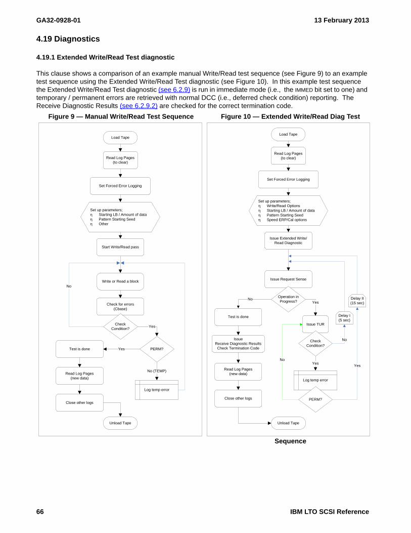
GA32-0928-01 13 February 2013
4.19 Diagnostics
4.19.1 Extended Write/Read Test diagnostic
This clause shows a comparison of an example manual Write/Read test sequence (see Figure 9) to an example test sequence using the Extended Write/Read Test diagnostic (see Figure 10). In this example test sequence the Extended Write/Read Test diagnostic (see 6.2.9) is run in immediate mode (i.e., the IMMED bit set to one) and temporary / permanent errors are retrieved with normal DCC (i.e., deferred check condition) reporting. The Receive Diagnostic Results (see 6.2.9.2) are checked for the correct termination code.
Figure 9 — Manual Write/Read Test Sequence Figure 10 — Extended Write/Read Diag Test
Sequence
Read Log Pages(to clear)
Set Forced Error Logging
Load Tape
Set up parameters;η Starting LB / Amount of dataη Pattern Starting Seedη Other
Start Write/Read pass
Write or Read a block
Check for errors(Cbase)
Check Condition?
No
PERM?
Yes
Log temp error
No (TEMP)
Test is done
Read Log Pages(new data)
Close other logs
Unload Tape
Yes
Read Log Pages(to clear)
Set Forced Error Logging
Load Tape
Set up parameters;η Write/Read Optionsη Starting LB / Amount of dataη Pattern Starting Seedη Speed ERP/Cal options
Issue Extended Write/Read Diagnostic
Test is done
Read Log Pages(new data)
Close other logs
Unload Tape
Issue Request Sense
Operation in Progress?
No
IssueReceive Diagnostic ResultsCheck Termination Code
Log temp error
PERM?
Yes
Yes
No
Delay I(5 sec)
Delay II(15 sec)
Yes
Issue TUR
Check Condition?
No
66 IBM LTO SCSI Reference

13 February 2013 GA32-0928-01
4.20 Error history (i.e., drive dump)
4.20.1 Error history overview
Error history is data collected by a device to aid in troubleshooting errors.
The READ BUFFER command (see 5.2.17) provides a method for retrieving error history from the device (see 4.20.2).
All Ultrium devices support retrieving a drive dump using data mode (i.e., 02h) with buffer ID 01h. This drive dump contains a snapshot of the current debug information (i.e., the contents of the operation tracing at a specific point in time) as well as additional snapshots using development specific algorithms designed to provide the best chance of capturing data to debug problems.
Beginning in Ultrium 6, error history may be retrieved using the method defined in SPC-4 and described in the rest of this clause. Note that there are some areas which differ from the behavior specified in SPC-4.
4.20.2 Retrieving error history with the READ BUFFER command
The error history is retrieved using a sequence of READ BUFFER commands on one I_T_L nexus.
Tracing of drive operation is returned using error history snapshots. An error history snapshot is the contents of the operation tracing at a specific point in time, created by the device at vendor specific times or requested by the application client using the READ BUFFER command with certain buffer IDs.
The I_T_L nexus being used to retrieve an error history snapshot is called the error history I_T_L nexus. Only one I_T_L nexus is allowed to retrieve an error history snapshot at a time.
To retrieve the complete error history, an application client uses one I_T_L nexus to:
1) create an error history snapshot if one does not already exist, establish the I_T_L nexus as the error history I_T_L nexus, and retrieve the drive tracing directory by sending a READ BUFFER command (see 5.2.17) with:A) the MODE field set to 1Ch (i.e., error history);B) the BUFFER ID field set to one of the following:
a) If the error history I_T_L nexus is expected to be valid:A) 00h (i.e., return error history directory);B) 01h (i.e., return error history directory and create new snapshot);
b) if the application client has knowledge that the error history I_T_L nexus is no longer valid:A) 02h (i.e., return error history directory and establish new error history I_T_L nexus); orB) 03h (i.e., return error history directory, establish new error history I_T_L nexus, and create
new snapshot);C) the BUFFER OFFSET field set to 000000h; andD) the ALLOCATION LENGTH field set to at least 2 088 (i.e., large enough to transfer the complete error
history directory);2) retrieve the error history. The application client uses a Data-In Buffer size that is a multiple of the offset
boundary indicated in the READ BUFFER descriptor (see 5.2.17.3). Each buffer ID indicated in the errorhistory directory is a different type of trace or error history. Buffer ID EFh contains a description of eachtrace (i.e., error history) that is available (see 5.2.17.7.3.4). For each buffer ID indicated in the errorhistory directory in the range of 10h to EFh, the application client may retrieve the trace by sending oneor more READ BUFFER commands (see 5.2.17) as follows:1) send the first READ BUFFER command with:
a) the MODE field set to 1Ch (i.e., error history);b) the BUFFER ID field set to the buffer ID (i.e., an error history data buffer);c) the BUFFER OFFSET field set to 000000h; andd) the ALLOCATION LENGTH field set to the size of the Data-In Buffer;
2) until the number of bytes returned by the previous READ BUFFER command does not equal thespecified allocation length and/or the total number of bytes returned from the buffer ID equals themaximum available length indicated in the error history directory, send zero or more additional READBUFFER commands with:
IBM LTO SCSI Reference 67

GA32-0928-01 13 February 2013
a) the MODE field set to 1Ch (i.e., error history);b) the BUFFER ID field set to the buffer ID (i.e., an error history data buffer);c) the BUFFER OFFSET field set to the previous buffer offset plus the previous allocation length; andd) the ALLOCATION LENGTH field set to the size of the Data-In Buffer;
and3) clear the error history I_T_L nexus and, depending on the buffer ID, release the error history snapshot by
sending a READ BUFFER command with:A) the MODE field set to 1Ch (i.e., error history);B) the BUFFER ID field set to:
a) FEh (i.e., clear error history I_T_L nexus) (see 5.2.17.7.4); orb) FFh (i.e., clear error history I_T_L nexus and release snapshot) (see 5.2.17.7.5);
C) the BUFFER OFFSET field set to any value allowed by table 76 (e.g., 000000h); andD) the ALLOCATION LENGTH field set to any value allowed for the chosen BUFFER ID field value (see
5.2.17.7.4 or 5.2.17.7.5) (e.g., 000000h).
While an error history snapshot exists, the device does not modify the error history snapshot to reflect any changes to the error history. This does not include the emergency dump (see 5.2.17.7.3.2) or prioritized flash dumps (see 5.2.17.7.3.3). These dumps are generated internally and may be generated or modified at any time, even while an error history snapshot exists.
The device clears the established error history I_T_L nexus and does not release the error history snapshot:
a) upon processing of a READ BUFFER command on the error history I_T_L nexus with:A) the MODE field set to 1Ch (i.e., error history); andB) the BUFFER ID field set to FEh (i.e., clear error history I_T_L nexus) (see 5.2.17.7.4);or
b) if an I_T nexus loss occurs on the error history I_T_L nexus.
The device clears the established error history I_T_L nexus and releases the error history snapshot:
a) upon processing of a READ BUFFER command using the same I_T_L nexus that was used to establish the snapshot with:A) the MODE field set to 1Ch (i.e., error history); andB) the BUFFER ID field set to FFh (i.e., clear error history I_T_L nexus and release snapshot) (see
5.2.17.7.5);b) if a power on occurs;c) if a hard reset occurs; ord) if a device reset occurs.
If a new error history snapshot is created by one of the supported methods or by internal algorithms while an error history snapshot exists, the new snapshot overwrites the existing error history snapshot (i.e., MODE[1Ch] 10h: Current error history snapshot (see 5.2.17.7.3.1 on page 117)) or drive dump (i.e., Buffer ID 01h with MODE set to 2h), then an attempt to read an error history at a non-zero offset will be rejected with a CHECK CONDITION with the sense key set to ILLEGAL REQUEST and the additional sense code set to ERROR HISTORY SNAPSHOT RELEASED. This notifies the application that the snapshot (i.e., buffer ID) being retrieved has been overwritten.
68 IBM LTO SCSI Reference

13 February 2013 GA32-0928-01
5. SCSI Commands
5.1 SCSI Commands Overview
This chapter describes the SCSI commands supported (LUN 0).
The following SCSI command descriptions have a table describing the fields in the Command Descriptor Block (CDB), similar to the style used in the American National Standard of the National Committee for Information Technology Standards (NCITS) documents.
Any data required by each command follow these descriptions and are described in a “term-definition” format. In this format, the bits or bytes to be described are highlighted and listed on the left. The definition for the bits or bytes is to the right (not highlighted).
Parameters are described in Parameters for SCSI Commands (see 6. on page 185).
5.1.1 Unsupported SCSI Commands
Certain commands or features of some commands defined in SPC-4 or SSC-3 are not currently supported but may be in the future.
The LUN field in the CDB has been obsoleted in SCSI-3 and is ignored for every command.
Binary numbers are represented by numbers followed by b. Hexadecimal numbers are represented by 0-9 and A-F followed by h. Numbers with no suffix can be assumed to be decimal.
The Read Buffer and Write Buffer commands are supported but not all buffers are described in this document because many buffers are intended only to be read or written by the Service Representative or by Manufacturing. OEM customers who intend to support host microcode download on a new platform should contact IBM for a complete description of the Write Buffer command for this purpose. Note that new microcode may also be loaded without requiring the use of the SCSI Write Buffer command, by using the Field Microcode Replacement (FMR) tape process described in the maintenance information manual for this product.
5.1.2 Supported SCSI Commands
This device accepts commands on LUN 0 for drive related commands (i.e., Peripheral Device Type returned in Standard Inquiry is Sequential Access Device). When in a library this device also accepts commands on LUN 1 for library related commands (i.e., Peripheral Device Type returned in Standard Inquiry is Medium Changer Device).
5.1.2.1 Supported SCSI Commands on LUN 1
The list of commands supported on LUN 1 is dependant on the Library in which the drive is contained. To determine the model of the library in which the drive is contained, use the INQUIRY command. Bytes 8-15 contain the T10 VENDOR IDENTIFICATION. Bytes 16 - 31 contain the PRODUCT IDENTIFICATION.
This document contains no additional information about commands supported on LUN 1. For a list of all commands supported please see the appropriate Library SCSI Reference.
5.1.2.2 Supported SCSI Commands on LUN 0
Table 27 provides a list of all commands supported by this product for the sequential access device (i.e., LUN 0). For each command, the operation code, reference page for this specification, and applicability of certain conditions to the command are shown in Table 27.
It is strongly recommended that device drivers or host software implement device reservations using the RESERVE/RELEASE commands or the PERSISTENT RESERVE OUT/PERSISTENT RESERVE IN commands. It is also strongly recommended that host software use the Append-only mode (also known as Data-safe mode) (see 4.1.3 on page 25) as it helps cover the cases where reservations are lost or the drive
IBM LTO SCSI Reference 69

GA32-0928-01 13 February 2013
reboots unexpectedly.
Table 27 — Supported Common SCSI Commands (part 1 of 2)
Command NameOperation
CodePage
Applicable Conditions b
RVC UAT NRD WRP MFC DCC DEA
ALLOW OVERWRITE 82h 73 Y Y Y - - - -
ERASE 19h 74 Y Y Y Y Y Y Y
FORMAT MEDIUM 04h 75 Y Y Y Y Y Y Y
INQUIRY 12h 77 - - - - - - -
LOAD/UNLOAD 1Bh 83 Y Y - - Y Y Y
LOCATE(10/16) 2Bh/92h 85 Y Y Y - Y Y Y
LOG SELECT 4Ch 87 Y Y - - - - -
LOG SENSE 4Dh 88 - - - - - - -
MODE SELECT (6/10) 15h/55h 89 Y Y - - - - -
MODE SENSE (6/10) 1Ah/5Ah 91 - Y - - - - -
PERSISTENT RESERVE IN 5Eh 93 Y Y - - - - -
PERSISTENT RESERVE OUT 5Fh 99 Y c Y - - - - -
PREVENT ALLOW MEDIUM REMOVAL 1Eh 102 - Y - - - - -
READ 08h 103 Y Y Y - Y Y Y
READ ATTRIBUTE 8Ch 104 Y Y - - - Y -
READ BLOCK LIMITS 05h 108 - Y - - - - -
READ BUFFER 3Ch 110 Y - - - - - -
READ DYNAMIC RUNTIME ATTRIBUTE D1h 120 - - - - - - -
READ POSITION 34h 125 Y Y Y - - - -
RECEIVE DIAGNOSTIC RESULTS 1Ch 132 Y Y - - - - -
RELEASE UNIT (6/10) a 17h/57h 133 - d Y - - - - -
REPORT DENSITY SUPPORT 44h 134 - Y - - - - -
REPORT LUNs A0h 137 - - - - - - -
REPORT SUPPORTEDOPERATION CODE
A3h[0Ch] 139 - Y - - - - -
REPORT SUPPORTEDTASK MANAGEMENT FUNCTIONS
A3h[0Dh] 148 - Y - - - - -
REPORT TIMESTAMP A3h[0Fh] 150 - Y - - - - -
REQUEST SENSE 03h 152 - - - - - - -
RESERVE UNIT (6/10) a 16h/56h 159 Y d Y - - - - -
REWIND 01h 160 Y Y Y - Y Y Y
SECURITY PROTOCOL IN (SPIN) A2h 161 Y Y - - - - -
SECURITY PROTOCOL OUT (SPOUT) B5h 162 Y Y - - Y - -
SEND DIAGNOSTIC 1Dh 163 Y Y - - Y - -
SET CAPACITY 0Bh 165 Y Y Y Y Y Y Y
SET TIMESTAMP A4h[0Fh] 167 Y Y - - - Y -
SPACE (6/16) 11h/91h 169 Y Y Y - Y Y Y
70 IBM LTO SCSI Reference

13 February 2013 GA32-0928-01
TEST UNIT READY 00h 171 Y Y Y - - Y -
VERIFY 13h 172 Y Y Y - Y Y Y
WRITE 0Ah 174 Y Y Y Y Y Y Y
WRITE DYNAMIC RUNTIME ATTRIBUTE D2h 181 - - - - - - -
WRITE ATTRIBUTE 8Dh 175 Y Y - Y - Y -
WRITE BUFFER 3Bh 178 Y Y - - - - -
WRITE FILEMARKS (6) 10h 183 Y Y Y Y Y Y Y
Note 1 - The behavior for all commands is as defined in the following SCSI-3 specifications unless otherwise indicated:
SSC-4 (SCSI Stream Commands - 4)SPC-4 (SCSI Primary Commands-4)
a The RESERVE/RELEASE commands are defined in SPC-2 (SCSI Primary Commands-2)b Applicable Conditions are as follows:
Y = condition applies to the command- = condition does not apply to the commandRVC = reservation conflictUAT = unit attentionNRD = not readyWRP = write protect. These are also referred to as “write-type” commands.MFC = medium format corrupted. These commands are also considered Medium Access CommandsDCC = deferred check conditionDEA = deferred error (DCC) affinity (see 4.16.3)
c Reported as appropriate for the type of Service Action and Reservation Type requested and the current reservation state of the drive.
d The drive sets the CRH bit to one in the parameter data returned by the REPORT CAPABILITIES service action of the PERSISTENT RESERVE IN command. This indicates that in the presence of a Persistent Reservation, a RELEASE(6) or RELEASE(10) command will complete with GOOD status, but the persistent reservation will not be released, if the command is received from:
a) An I_T nexus that is a persistent reservation holder; orb) An I_T nexus that is registered if a registrants only type persistent reservation is present.
In all other cases, the RELEASE(6)/RELEASE(10) command will be rejected with a RESERVATION CONFLICT.The drive sets the CRH bit to one in the parameter data returned by the REPORT CAPABILITIES service action of the PERSISTENT RESERVE IN command. This indicates that in the presence of a Persistent Reservation, A RESERVE(6) or RESERVE(10) command will complete with GOOD status, but no reservation will be established and the persistent reservation will not be changed, if the command is received from:
a) An I_T nexus that is a persistent reservation holder; orb) An I_T nexus that is registered if a registrants only type persistent reservation is present.
In all other cases, the RESERVE(6)/RESERVE(10) command will be rejected with a RESERVATION CONFLICT.
Table 27 — Supported Common SCSI Commands (part 2 of 2)
Command NameOperation
CodePage
Applicable Conditions b
RVC UAT NRD WRP MFC DCC DEA
IBM LTO SCSI Reference 71

GA32-0928-01 13 February 2013
5.1.2.3 Control Byte Definition
This description of the control byte fields is to be used for all of the supported commands. The control byte occurs in the last byte of a command, that is, byte 5 (6-byte commands), byte 9 (10-byte commands), byte 11 (12-byte commands), or byte 15 (16-byte commands). Table 28 shows the bit significance of the control byte.
Bit Description1-6 Vendor specific: 00b5-3 Reserved: 000b2 NACA (Normal ACA): 0b1 Obsolete: 0b0 Obsolere: 0b
Table 28 — Control Byte Definition
ByteBit
7 6 5 4 3 2 1 0
5, 9, or 11 Vendor specific Reserved NACA Obsolete Obsolete
72 IBM LTO SCSI Reference

13 February 2013 GA32-0928-01
5.2 SCSI Commands Listing
5.2.1 ALLOW OVERWRITE - (82h)
When append-only mode is enabled an application client may issue the ALLOW OVERWRITE command to enable the overwrite of the medium at a non-append point. The processing of the ALLOW OVERWRITE command sets the allow_overwrite and allow_overwrite_position variables as specified in Append-only mode (also known as Data-safe mode) (see 4.1.3 on page 25).
The ALLOW OVERWRITE field specifies what type of overwrite is allowed. Table 30 defines the actions for the value specified in the ALLOW OVERWRITE field.
If the ALLOW OVERWRITE field is set to Current Position (i.e., 1h), then:
a) the PARTITION field shall be set to the active partition; andb) the LOGICAL OBJECT IDENTIFIER field shall be set to the current position.
If the ALLOW OVERWRITE field is set to Current Position (i.e., 1h), then the allow_overwrite_position variable shall be set to the current position.
If the ALLOW OVERWRITE field is not set to Current Position (i.e., 1h), then the PARTITION field and LOGICAL OBJECT IDENTIFIER field shall be ignored.
The device server shall terminate the command with CHECK CONDITION status with the sense key set to ILLEGAL REQUEST and the additional sense code set to SEQUENTIAL POSITIONING ERROR if:
a) the ALLOW OVERWRITE field is set to Current Position (i.e., 1h); andb) the logical position of the medium is not at the location specified by the PARTITION field and LOGICAL
OBJECT IDENTIFIER field.
If the device server terminates that command with any status other than GOOD, then the allow_overwrite variable shall be set to Disabled and the allow_overwrite_position variable shall be set to invalid.
Table 29 — ALLOW OVERWRITE CDB
ByteBit
7 msb 6 5 4 3 2 1 0 lsb
0 OPERATION CODE (82h)
1 Reserved
2 Reserved ALLOW OVERWRITE
3 PARTITION
4 (MSB)LOGICAL OBJECT IDENTIFIER
11 (LSB)
12Reserved
14
15 Control Byte (see 5.1.2.3)
Table 30 — ALLOW OVERWRITE field definition
Value Definition
0h The allow_overwrite variable shall be set to Disabled
1h The allow_overwrite variable shall be set to Current Position
2h The allow_overwrite variable shall be set to Format
3h-FhThe command shall be rejected with CHECK CONDITIONstatus with the sense key set to ILLEGAL REQUEST and the additional sense code set to INVALID FIELD IN CDB.
IBM LTO SCSI Reference 73

GA32-0928-01 13 February 2013
5.2.2 ERASE - 19h
EOD is written at the current position, which marks it as end of data. After the command is successfully completed, the drive is positioned immediately before End Of Data (not End Of Tape).
The following parameters apply:
• LONG: Value Description0b No further writing occurs after EOD is written.1b The Data Set Separator (DSS) pattern is written from the new EOD to the end of the current
partition to overwrite any data that is currently on the tape after the current logical position.
• IMMED (Immediate): Value Description0b Status is not returned until after the command has completed.1b The device validates the command and waits for any previous command from any server to
complete, including any immediate commands that are currently being processed. It also waits for any buffered data to be flushed to tape. It then reports a DEFERRED ERROR for any preceding command or buffered data, if any. If there is no deferred error, the drive reports GOOD status and initiates processing the command.
Table 31 — ERASE CDB
ByteBit
7 6 5 4 3 2 1 0
0 OPERATION CODE (19h)
1 Reserved IMMED LONG
2 Reserved
3 Reserved
4 Reserved
5 Control Byte (see 5.1.2.3)
WARNING WARNINGA long erase of a partitioned volume from BOP does not erase all data on the volume. It erases all data on the current partition but does not affect any other partitions. To erase all logical objects on the volume, issue a FORMAT MEDIUM command with the FORMAT field set to 0h then issue a long erase
WARNING WARNING
when positioned at BOP.
74 IBM LTO SCSI Reference

13 February 2013 GA32-0928-01
5.2.3 FORMAT MEDIUM - 04h
The FORMAT MEDIUM command (see table 32) is used to prepare the medium for use by the logical unit. If there are logical objects in the buffer when processing of a FORMAT MEDIUM command begins, or if the medium is not at beginning-of-partition 0 (BOP 0), then the command is rejected with CHECK CONDITION status with the sense key set to ILLEGAL REQUEST and the additional sense code set to POSITION PAST BEGINNING OF MEDIUM.
The FORMAT MEDIUM command shall function in the constraints dictated by any capacity changes resulting from a previous SET CAPACITY command that was performed on the mounted volume (i.e., The Set Capacity command controls the maximum capacity allowed for the volume and the Format Medium command works inside those constraints).
The FORMAT MEDIUM command is not allowed against a WORM cartridge. If a WORM cartridge is loaded when the FORMAT MEDIUM command is received, then the command will be rejected with CHECK CONDITION status. The sense key shall be set to DATA PROTECT and the additional sense code shall be set to WORM MEDIUM - OVERWRITE ATTEMPTED.
At the successful completion of a FORMAT MEDIUM command, the medium shall be positioned at BOP 0.
During the format operation, the device server shall respond to commands as follows:
a) in response to all commands except REQUEST SENSE and INQUIRY, the device server shall return CHECK CONDITION unless a reservation conflict exists. In that case RESERVATION CONFLICT status shall be returned; or
b) in response to the REQUEST SENSE command, assuming no error has occurred, the device server shall return a sense key of NOT READY and the additional sense code shall be set to LOGICAL UNIT NOT READY, FORMAT IN PROGRESS, with the sense key specific bytes set for process indication (see SPC-4).
An immediate (IMMED) bit of zero specifies the device server shall not return status until the FORMAT MEDIUM command has completed. An IMMED bit of one specifies the device server shall return status as soon as the valid medium location has been verified and the command descriptor block of the FORMAT MEDIUM command has been validated. If CHECK CONDITION status is returned for a FORMAT MEDIUM command with an IMMED bit of one, the format operation shall not be performed.
The VERIFY bit shall be set to zero. The drive does not perform any verification of the format.
Table 32 — FORMAT MEDIUM CDB
ByteBit
7 6 5 4 3 2 1 0
0 OPERATION CODE (04h)
1 Reserved VERIFY IMMED
2 Reserved FORMAT
3 (MSB)TRANSFER LENGTH
4 (LSB)
5 Control Byte (see 5.1.2.3)
IBM LTO SCSI Reference 75

GA32-0928-01 13 February 2013
The FORMAT field is specified in table 33.
If the FORMAT field is 0h, the logical unit shall format the volume to a single partition. A valid FORMAT MEDIUM command with 0h in the FORMAT field shall cause all data on the entire physical volume to be lost.
If the FORMAT field is 1h, the logical unit shall partition the medium using the current mode data from the Medium Partition mode page (see 6.6.13). If none of the mode bits SDP, FDP, or IDP are set to one, the device server shall return CHECK CONDITION. The sense key shall be set to ILLEGAL REQUEST with the addition sense code set to PARAMETER VALUE INVALID. If insufficient space exists on the medium for the requested partition sizes, the device server shall return CHECK CONDITION status. The sense key shall be set to MEDIUM ERROR and the additional sense code shall be set to VOLUME OVERFLOW. A valid FORMAT MEDIUM command with 1h in the FORMAT field causes all data on the entire physical volume to be lost.
If the FORMAT field is 2h, the logical unit shall perform the operations equivalent to a FORMAT field of 0h followed by a FORMAT field of 1h. A valid FORMAT MEDIUM command with 2h in the FORMAT field causes all data on the entire physical volume to be lost.
When the FORMAT field contains 1h or 2h, some errors related to mode page field contents may not be detected until the FORMAT MEDIUM command is processed. Therefore, some error conditions described in MP 11h: Medium Partition Page (see 6.6.13 on page 383) may be returned in response to a FORMAT MEDIUM command with 1h or 2h in the FORMAT field.
The TRANSFER LENGTH shall be zero.
Table 33 — FORMAT field
Code Description Cartridge Support
0h Use default format Ultrium 4 and later Data cartridge
1h Partition medium Ultrium 5 and later Data cartridge
2h Default format then partition Ultrium 5 and later Data cartridge
3h-7h Reserved
8h-Fh Vendor specific Not Supported
76 IBM LTO SCSI Reference

13 February 2013 GA32-0928-01
5.2.4 INQUIRY - 12h
The INQUIRY command instructs the drive to return data about itself to the initiator.
If the Enable Vital Product Data (EVPD) field is set to 0 and the PAGE CODE field is set to 00h, then Standard Inquiry Data is returned (see 5.2.4.1).
If the Enable Vital Product Data (EVPD) field is set to one and the PAGE CODE field is set to 00h, then the Supported Vital Product Data Pages page is returned (see 6.3.1). This page lists the VPD pages that are supported by the drive in this configuration.
If the Enable Vital Product Data (EVPD) field is set to one and the PAGE CODE field is not set to 00h, then a VPD page is requested and, if the VPD page is supported in the current configuration, that page is returned. The VPD pages are described in 6.3 Inquiry Vital Product Data Parameters (IP).
If the preceding conditions do not apply, the logical unit returns CHECK CONDITION status with the Sense Key set to ILLEGAL REQUEST and the additional sense code set to INVALID FIELD IN CDB (i.e., 5/2400h).
5.2.4.1 Standard Inquiry Data
In drives that are not configured with the eServer™ attachment feature, Standard Inquiry Data for a valid LUN is described in table 35.
Table 34 — INQUIRY CDB
ByteBit
7 6 5 4 3 2 1
0 OPERATION CODE (12h)
1 Reserved EVPD
2 PAGE CODE
3 Reserved
4 ALLOCATION LENGTH
5 Control Byte (see 5.1.2.3)
Table 35 — Standard INQUIRY data valid LUN format (part 1 of 2)
BitByte
7 6 5 4 3 2 1 0
0 PERIPHERAL QUALIFIER PERIPHERAL DEVICE TYPE
1 RMB Reserved
2 version (06h)
3 Obsolete Obsolete NACA (0) HISUP (0) RESPONSE DATA FORMAT (2h)
4 ADDITIONAL LENGTH (n-4)
5 SCCS (0) ACC (0) TPGS (00b) 3PC (0) Reserved PROTECT
6 Obsolete ENCSRV (0) VS(0) MULTIP Obsolete Obsolete Obsolete ADDR16(0)
7 Obsolete Obsolete WBUS16(0) SYNC(0) Obsolete Obsolete CmdQue VS(0)
8 (MSB)T10 VENDOR IDENTIFICATION(“IBM “)
15 (LSB)
16 (MSB)PRODUCT IDENTIFICATION
31 (LSB)
32 (MSB)PRODUCT REVISION LEVEL (YMDV)
35 (LSB)
IBM LTO SCSI Reference 77

GA32-0928-01 13 February 2013
36 Reserved AutDis
37 Obsolete
38 PROTOCOL IDENTIFIER MAXIMUM SPEED SUPPORTED
39 Restricted Reserved FIPS
40 Reserved
41 OEM Specific
42Reserved
55
56 Reserved CLOCKING(0) QAS(0) IUS(0)
57 Reserved
58 (MSB)SAM-5 T10/2104-D revision 4 (00A2h)
59 (LSB)
60 (MSB) if SAS drive, then SAS-2r16 (0C28h)if Fibre Channel drive, then FCP-4 T10/1828-D revision 02b (0A45h)61 (LSB)
62 (MSB)SPC-4, no revision claimed (0460h)
63 (LSB)
64 (MSB)SSC-4 (no version claimed) (0520h)
65 (LSB)
66 (MSB)ADT-2 T10/1742-D revision 09 (0A28h)
67 (LSB)
68 (MSB)ADC-3 T10/1895-D revision 04 (0502h)
69 (LSB)
Table 35 — Standard INQUIRY data valid LUN format (part 2 of 2)
BitByte
7 6 5 4 3 2 1 0
78 IBM LTO SCSI Reference
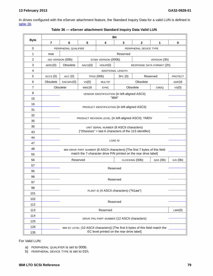
13 February 2013 GA32-0928-01
In drives configured with the eServer attachment feature, the Standard Inquiry Data for a valid LUN is defined in table 36.
For Valid LUN:
a) PERIPHERAL QUALIFIER is set to 000b.b) PERIPHERAL DEVICE TYPE is set to 01h.
Table 36 — eServer attachment Standard Inquiry Data Valid LUN
ByteBit
7 6 5 4 3 2 1 0
0 PERIPHERAL QUALIFIER PERIPHERAL DEVICE TYPE
1 RMB Reserved
2 ISO VERSION (00b) ECMA VERSION (000b) VERSION (3h)
3 AERC(0) Obsolete NACA(0) HISUP(0) RESPONSE DATA FORMAT (2h)
4 ADDITIONAL LENGTH
5 SCCS (0) ACC (0) TPGS (00b) 3PC (0) Reserved PROTECT
6 Obsolete ENCSRV(0) VS(0) MULTIP Obsolete ADR16
7 Obsolete WBS16 SYNC Obsolete CMDQ VS(0)
8 VENDOR IDENTIFICATION (in left-aligned ASCII)"IBM"15
16PRODUCT IDENTIFICATION (in left-aligned ASCII)
31
32PRODUCT REVISION LEVEL (in left-aligned ASCII): YMDV
35
36 UNIT SERIAL NUMBER (8 ASCII characters)["20ssssss" = last 6 characters of the 11S identifier]43
44LOAD ID
47
48 IBM DRIVE PART NUMBER (8 ASCII characters) [The first 7 bytes of this field match the 7-character drive P/N printed on the rear drive label]55
56 Reserved CLOCKING (00b) QAS (0b) IUS (0b)
57Reserved
95
96Reserved
97
98PLANT ID (4 ASCII characters) ("N1øø")
101
102Reserved
112
113 Reserved LIBR(0)
114DRIVE FRU PART NUMBER (12 ASCII characters)
125
126 IBM EC LEVEL (10 ASCII characters)) [The first 6 bytes of this field match the EC level printed on the rear drive label]135
IBM LTO SCSI Reference 79

GA32-0928-01 13 February 2013
c) RMB is set to 1b to indicate that the medium is removable.
For Invalid LUN:
a) PERIPHERAL QUALIFIER is set to 011b.b) PERIPHERAL DEVICE TYPE is set to 1Fh.c) RMB is set to 0b to indicate that the medium is not removable.
For all devices:
a) The Additional Length field specifies how many bytes follow. This value is subject to change. It is strongly recommended that the user parse the data returned by using the ADDITIONAL LENGTH field.
b) PROTECT: (see Logical block protection (see 4.5 on page 35))c) ADR16 field is set to 0.d) WBS16 field is set to 0.e) SYNC field is set to 0.f) CMDQ field is set to 1, which indicates that the drive supports tagged (simple) command queuing.g) CLOCKING field is set to 0.h) QAS field is set to 0, which indicates that the drive does not support quick arbitration and selection.i) IUS field is set to 0, which indicates that the drive does not support information unit transfers.j) VENDOR IDENTIFICATION returns IBM in ASCII with trailing blanks.k) PRODUCT VENDOR IDENTIFICATION returns ULTxxxx-TDy in ASCII with trailing blanks. If the drive is an
IBM drive, xxxx equals 3580; if it is an OEM drive, xxxx equals RIUM. The character y indicates the generation of the drive. See the table below for the value returned.
Table 37 — Product Identification Table
Generation c IBM Drive a OEM Drive a eServer Attachment enabled b
1 ULT3580-TD1 ULTRIUM-TD1 N/A
2 ULT3580-TD2 ULTRIUM-TD2 N/A
2 Half-height ULT3580-HH2 ULTRIUM-HH2 N/A
3 ULT3580-TD3 ULTRIUM-TD3 N/A
3 Half-height ULT3580-HH3 ULTRIUM-HH3 HH LTO Gen 3
4 ULT3580-TD4 ULTRIUM-TD4 N/A
4 Half-height ULT3580-HH4 ULTRIUM-HH4 HH LTO Gen 4
5 ULT3580-TD5 ULTRIUM-TD5 N/A
5 Half-height ULT3580-HH5 ULTRIUM-HH5 HH LTO Gen 5
6 ULT3580-TD6 ULTRIUM-TD6 -
6 Half-Height ULT3580-HH6 ULTRIUM-HH6 HH LTO Gen 6a IBM Tape Device Drivers will only configure Product IDs that are found in the columns entitled "IBM
Drive" and "OEM Drive".b IBM SCDD will only configure Product IDs that are found in the column entitled "eServer Attachment
Enabled".c For description of behaviors of devices prior to generation 5, see the IBM System Storage LTO Ultrium
Tape Drive: SCSI Reference (GA32-0450-10) which is found at the following URL http://publibfi.dhe.ibm.com/epubs/pdf/32045010.pdf
80 IBM LTO SCSI Reference

13 February 2013 GA32-0928-01
WARNING WARNINGDrives targeted to be installed in eServer hosts have the eServer Attachment enabled during manufacturing. Drives that have eServer Attachment enabled have several behaviors that are different from the drives without eServer Attachment enabled. Please see the following sections and look for eServer attachment differences:
WARNING WARNING
<Mode Page 2Fh: Behavior Configuration Mode Page, REWIND, WRITE FILE MARKS>.
l) PRODUCT REVISION LEVEL has four parts:A) Y is the last character of the year (for example, A indicates the year 2010)B) M is the month, in the alphanumeric set 1 through 9, A, B, or CC) D is the day, in the alphanumeric set 1 through 9, A through VD) V is the version, in the alphanumeric set 0 through 9, a through z, and A through Z, with 0 being the
earliest and Z the latest (to avoid interpretation errors, the characters i, l, and 0 are not used)m) Automation Disabled (AutDis) field set indicates that the drive is not capable of full automation function.
When this field is 0, it indicates that the drive is capable of full automation function.n) The OEM Specific field is for OEM specific reasons.o) The PROTOCOL IDENTIFIER field is defined by the PROTOCOL IDENTIFIER field defined in SPC-4 and copied
in table 38.
p) The MAXIMUM SPEED SUPPORTED field reports the maximum speed supported on the primary interface. The values for SAS attached devices are defined in table 39. The values for Fibre Channel attached devices are defined in table 40.
Table 38 — PROTOCOL IDENTIFER values
PROTOCOL
IDENTIFIERDescription
ProtocolStandard
0h Fibre Channel FCP-4
6h SAS Serial SCSI Protocol SAS-2
7h Automation/Drive Interface - Transport Protocol ADT-2
Table 39 — SAS MAXIMUM SPEED SUPPORTED values
Value Physical Link Rate
0h Unknown
8h 1.5 Gbps
9h 3.0 Gbps
Ah 6.0 Gbps
Table 40 — Fibre Channel MAXIMUM SPEED SUPPORTED values
Value Physical Link Rate
0h 1 Gb/s
1h 2 Gb/s
2h 4 Gb/s
3h 8 Gb/s
4h 10 Gb/s
others Reserved
IBM LTO SCSI Reference 81

GA32-0928-01 13 February 2013
q) The FIPS field indicates information about the code level as it relates to the Federal Information Processing Standards. The FIPS field values are defined in table 41.
Table 41 — FIPS field values
Value Description
00b Code level and base have never been certified by FIPS
01bCode level is built on top of a FIPS 140-2 certified code level but has not been certified since the change.
10b Reserved
11b Code level is a FIPS 140-2 certified code level
82 IBM LTO SCSI Reference

13 February 2013 GA32-0928-01
5.2.5 LOAD/UNLOAD - 1Bh
If the LOAD field is set to 1b and there is a tape in the drive, it is positioned to BOP 0. If the LOAD field is set to 1b and there is no tape in the drive, CHECK CONDITION status is returned with Sense Key set to Not Ready and the additional sense code set to MEDIUM NOT PRESENT (2/3A00h).
If the LOAD field is set to 0b, there is a tape in the drive, and medium removal prevention has not been set, then the tape is unloaded and ejected. If the LOAD field is set to 0b, there is a tape in the drive, and medium removal prevention has been set, then CHECK CONDITION status is returned with the Sense Key set to ILLEGAL REQUEST and the additional sense code set to MEDIUM REMOVAL PREVENTED (5/5302h).
If the LOAD field is set to 0b and the tape is in the ejected position, the command is presented with CHECK CONDITION status and associated sense data of 2/0402h (NOT READY, INITIALIZATION REQUIRED). If the LOAD field is set to 0b and there is no cartridge present, the command is presented with CHECK CONDITION status and associated data of 2/3A00h (NOT READY, MEDIUM NOT PRESENT).
If the Immediate (IMMED) field is set to 1b, then the drive validates the command and waits for any previous command from any server to complete, including any immediate commands that are currently being processed. It also waits for any buffered data to be flushed to tape. It then reports a DEFERRED ERROR for any preceding command or buffered data, if appropriate. If there is no deferred error, the drive reports GOOD status and initiates the command. If the IMMED field is set to 0b, then status is not returned until after the command has completed.
The Retension (RETEN) field is not supported and will be ignored.
The End Of Tape (EOT) field is not supported and should be set to 0b. If the EOT field is set to 1b, then CHECK CONDITION status is returned with the Sense Key is set to ILLEGAL REQUEST and the additional sense code set to INVALID FIELD IN CDB (5/2400h).
Table 42 — LOAD/UNLOAD CDB
ByteBit
7 6 5 4 3 2 1 0
0 OPERATION CODE (1Bh)
1 Obsolete (LUN) (ignored) Reserved IMMED
2 Reserved
3 Reserved
4 Reserved HOLD EOT (0) RETEN (0) LOAD
5 Control Byte (see 5.1.2.3)
IBM LTO SCSI Reference 83

GA32-0928-01 13 February 2013
Table 43 describes the behaviors for the command.
Table 43 — LOAD/UNLOAD actions depending on Load and Hold bit settings and medium position
Medium Position on command
receipt
Load Hold StatusBehavior and Medium Position at
command completion
No tape present 0 xCheck Condition Status is returned with Not Ready, Medium Not Present (2/3A00)
No action is takenNo tape present
No tape present 1 xCheck Condition Status is returned with Not Ready, Medium Not Present (2/3A00)
No action is takenNo tape present
Ejected Position 0 xCheck Condition Status is returned with Not Ready, Initializing Command Required (2/0402)
No action is takenEjected Position
Ejected Position 1 0 Good Status returnedSeated and tape is threaded and ready for access at LBA 0 of partition 0
Ejected Position 1 1 Good Status returnedSeated with Cartridge Memory (CM) accessible but tape is not threaded
Seated but tape not threaded
0 0 Good Status returned Ejected Position
Seated but tape not threaded
0 1 Good Status returnedNo action taken Position it was at prior to command
Seated but tape not threaded
1 0 Good Status returnedSeated and tape is threaded and ready for access at LBA 0 of partition 0
Seated but tape not threaded
1 1 Good Status returnedNo action takenPosition it was at prior to command
Seated with tape threaded
0 0 Good Status returned Ejected Position
Seated with tape threaded
0 1 Good Status returnedSeated with Cartridge Memory (CM) accessible but tape is not threaded
Seated with tape threaded
1 0 Good Status returned
Seated and tape is rewound and ready for access at LBA 0 of partition 0(i.e. this is equal to issuing a rewind command)
Seated with tape threaded
1 1Check Condition Status is returned with Illegal Request, Invalid Field in CDB (5/2400)
No action is takenPosition it was at prior to command
84 IBM LTO SCSI Reference
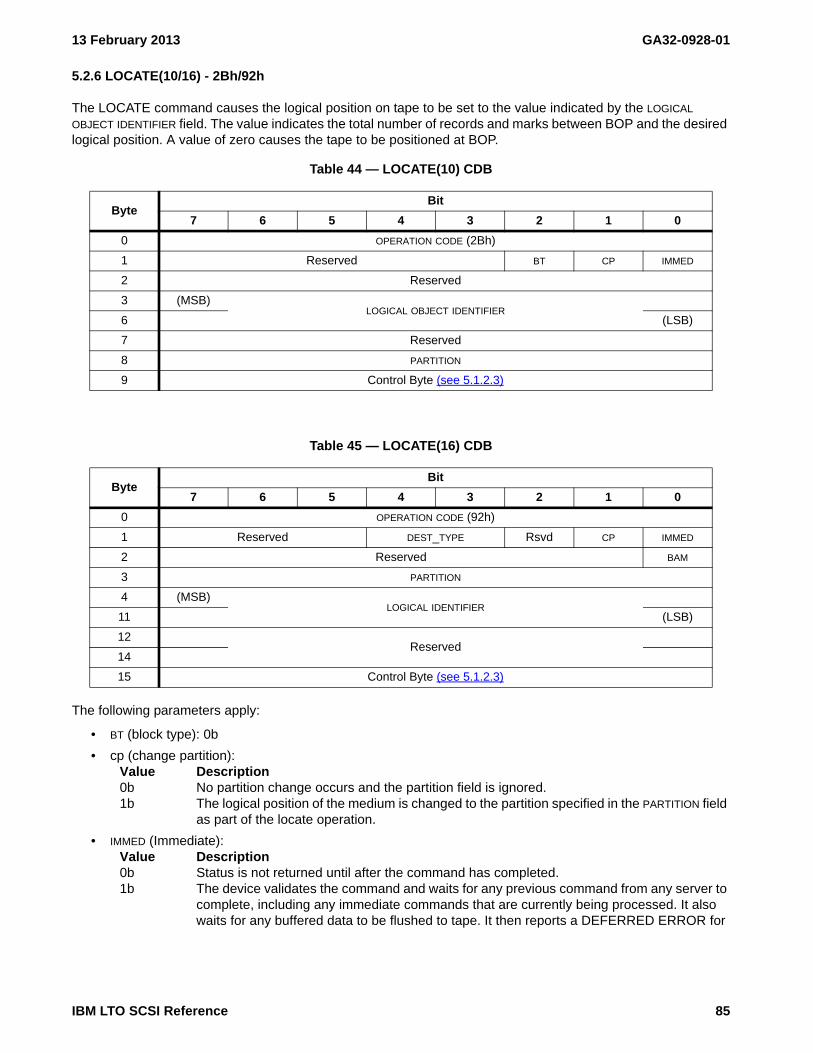
13 February 2013 GA32-0928-01
5.2.6 LOCATE(10/16) - 2Bh/92h
The LOCATE command causes the logical position on tape to be set to the value indicated by the LOGICAL OBJECT IDENTIFIER field. The value indicates the total number of records and marks between BOP and the desired logical position. A value of zero causes the tape to be positioned at BOP.
The following parameters apply:
• BT (block type): 0b
• cp (change partition): Value Description0b No partition change occurs and the partition field is ignored.1b The logical position of the medium is changed to the partition specified in the PARTITION field
as part of the locate operation.
• IMMED (Immediate): Value Description0b Status is not returned until after the command has completed.1b The device validates the command and waits for any previous command from any server to
complete, including any immediate commands that are currently being processed. It also waits for any buffered data to be flushed to tape. It then reports a DEFERRED ERROR for
Table 44 — LOCATE(10) CDB
ByteBit
7 6 5 4 3 2 1 0
0 OPERATION CODE (2Bh)
1 Reserved BT CP IMMED
2 Reserved
3 (MSB)LOGICAL OBJECT IDENTIFIER
6 (LSB)
7 Reserved
8 PARTITION
9 Control Byte (see 5.1.2.3)
Table 45 — LOCATE(16) CDB
ByteBit
7 6 5 4 3 2 1 0
0 OPERATION CODE (92h)
1 Reserved DEST_TYPE Rsvd CP IMMED
2 Reserved BAM
3 PARTITION
4 (MSB)LOGICAL IDENTIFIER
11 (LSB)
12Reserved
14
15 Control Byte (see 5.1.2.3)
IBM LTO SCSI Reference 85

GA32-0928-01 13 February 2013
any preceding command or buffered data, if any. If there is no deferred error, the drive reports GOOD status and initiates processing the command.
• PARTITION: The partition to locate to if the CP bit is 1b.
• DEST_TYPE (destination type): Used in conjunction with the LOGICAL IDENTIFIER field to locate to the appro-priate position of the medium.
Value Description00b The LOGICAL IDENTIFIER field is interpreted as a logical object identifier. The Logical Position
upon successful completion is on the BOP side of the logical object.01b The LOGICAL IDENTIFIER field is interpreted as a logical file identifier. The Logical Position
upon successful completion is on the BOP side of the logical file.011b The LOGICAL IDENTIFIER field is ignored and the logical position upon completion is EOD
(end-of-data) of the partition specified in the PARTITION field if the CP bit is set to 1b or EOD of the current partition if the CP bit is set to 0b.
others Reserved
• LOGICAL OBJECT IDENTIFIER: The logical object identifier to which the medium is to be positioned.
• LOGICAL IDENTIFIER: The logical object identifier (if the DEST_TYPE is set to 00b) or the logical file identifier (if the DEST_TYPE is sest to 01b) to which the medium is to be positioned.
86 IBM LTO SCSI Reference

13 February 2013 GA32-0928-01
5.2.7 LOG SELECT - 4Ch
The LOG SELECT command causes log data on the drive to be reset to its default value or to be set to an initiator-specific value.
• Parameter Code Reset (PCR):
If the Parameter Code Reset (PCR) bit is set to one, then the PARAMETER LIST LENGTH shall be zero. The action taken by the drive is specified for the values of the Page Control (PC) field as follows:
Value Description00b no action is taken and GOOD status is returned.01b all resettable logs on the drive are reset to default values.10b no action is taken and GOOD status is returned.11b all resettable logs on the drive are reset to default values.
If the Parameter Code Reset (PCR) field is set to 0, the Parameter List Length is not 0. The action taken by the drive is specified for the values of the PC field as follows:
Value Description00b CHECK CONDITION status is returned with the Sense Key set to ILLEGAL REQUEST and the
additional sense code set to INVALID FIELD IN CDB (5/2400h).01b data from the server is written to the indicated logs, provided that the logs are writable.10b CHECK CONDITION status is returned with the Sense Key set to ILLEGAL REQUEST and the
additional sense code set to INVALID FIELD IN CDB (5/2400h).11b data from the server is written to the indicated logs, provided that the logs are writable.
• Save Page (SP): (0b)
For a list of supported page codes see LP 00h: Supported Log Pages (see 6.4.4 on page 272).
Table 46 — LOG SELECT CDB
ByteBit
7 6 5 4 3 2 1 0
0 OPERATION CODE (4Ch)
1 Reserved PCR SP
2 PC PAGE CODE
3 SUBPAGE CODE
4Reserved
6
7 (MSB)PARAMETER LIST LENGTH
8 (LSB)
9 Control Byte (see 5.1.2.3)
IBM LTO SCSI Reference 87

GA32-0928-01 13 February 2013
5.2.8 LOG SENSE - 4Dh
The LOG SENSE command causes log data to be sent to the initiator.
The log values returned are controlled by the Page Control (PC) field value as follows:
Value Description00b the maximum value for each log entry is returned.01b the current values are returned.10b the maximum value for each log entry is returned.11b the power-on values are returned.
NOTE 8 - For page 2Eh (TapeAlert) only, the PC field is ignored. Current values are always returned.
The Parameter Pointer Control (PPC) must be set to 0. Returning changed parameters is not supported. The Save Page (SP) field must be set to 0. Saved pages are not supported. The Parameter Pointer will be 0.
Cartridge-specific log parameter counts are set to 0 when a cartridge has successfully loaded.
WARNING WARNINGLog parameter data must be dynamically parsed as some parameters may not be present and other parameters
WARNING WARNING
may be inserted. The relative location of parameters have changed and are anticipated to continue to change.
For a list of supported page codes see LP 00h: Supported Log Pages (see 6.4.4 on page 272).
Table 47 — LOG SENSE CDB
ByteBit
7 6 5 4 3 2 1 0
0 OPERATION CODE (4Dh)
1 Reserved PPC SP
2 PC PAGE CODE
3 SUBPAGE CODE
4 Reserved
5 (MSB)PARAMETER POINTER
6 (LSB)
7 (MSB)ALLOCATION LENGTH
8 (LSB)
9 Control Byte (see 5.1.2.3)
88 IBM LTO SCSI Reference

13 February 2013 GA32-0928-01
5.2.9 MODE SELECT (6/10) - 15h/55h
The MODE SELECT commands are defined in SPC (see the latest version at http://www.t10.org/drafts.htm#SCSI3_CMNDSETS). This clause describes the specific implementation.
NOTE 9 - In the future, the length of the mode parameter list for Mode Sense Page Code 3Fh (All Pages) may exceed 255 bytes. At that time, use of the Mode Select (10) and Mode Sense (10) commands will be required in order to transfer all mode pages with one command. Some mode pages today exceed 255 bytes. For this reason, use of the Mode Select (6) and Mode Sense (6) commands is not recommended.
The following standards-based mode pages are supported:
MP 01h: Read-Write Error Recovery (see 6.6.5 on page 367)MP 02h: Disconnect-Reconnect (see 6.6.6 on page 369)MP 0Ah: Control (see 6.6.7 on page 371)MP 0Ah[01h]: Control Extension (see 6.6.8 on page 372)MP 0Fh: Data Compression (see 6.6.10 on page 375)MP 10h: Device Configuration (see 6.6.11 on page 377)MP 11h: Medium Partition Page (see 6.6.13 on page 383)MP 18h: Protocol-Specific Logical Unit (see 6.6.14 on page 388)MP 19h: Protocol specific port (see 6.6.15 on page 390)MP 1Ah: Power Condition (see 6.6.16 on page 393)MP 1Ch: Informational Exceptions Control (see 6.6.17 on page 395)MP 1Dh: Medium Configuration (see 6.6.18 on page 397)
Table 48 — MODE SELECT(6) CDB
ByteBit
7 msb 6 5 4 3 2 1 0 lsb
0 OPERATION CODE (15h)
1 Obsolete (LUN) PF Reserved SP
2Reserved
3
4 PARAMETER LIST LENGTH
5 Control Byte (see 5.1.2.3)
Table 49 — MODE SELECT(10) CDB
ByteBit
7 msb 6 5 4 3 2 1 0 lsb
0 OPERATION CODE (55h)
1 Obsolete (LUN) PF Reserved SP
2Reserved
6
7 (MSB)PARAMETER LIST LENGTH
8 (LSB)
9 Control Byte (see 5.1.2.3)
IBM LTO SCSI Reference 89

GA32-0928-01 13 February 2013
The following vendor-specific mode pages are also supported:
MP 24h: Vendor-Specific (see 6.6.19 on page 398) (see on page 399)MP 2Fh: Behavior Configuration (see 6.6.20 on page 403)MP 30h[02h]: Drive IP address and subnet mask - Device attribute settings (see 6.6.21.3.3 on page 414)MP 30h[03h]: Key manager IP address information - Device attribute settings (see 6.6.21.3.4 on
page 416)MP 30h[40h]: SkipSync - Device attribute settings (see 6.6.21.5.1 on page 418)MP 30h[42h]: End of partition behavior control - Device attribute settings (see 6.6.21.5.3 on page 422)MP 3Eh: Engineering Support (see 6.6.22 on page 423)
NOTE 10 - Mode page 3Eh is for engineering use only.
The following parameters apply:
• PF (Page Format): 1b
The PF bit is explicitly not checked.
• SP (Save Pages): Only allowed to be set to one when explicitly mentioned in the description of the specific mode page
• PARAMETER LIST LENGTH:
This field specifies the length in bytes of the mode parameter list that is transferred from the initiator to the target. A parameter list length of zero indicates that no data is transferred. This condition is not considered as an error.
The target terminates the command with CHECK CONDITION status with associated sense data of 5/1A00 (ILLEGAL REQUEST, PARAMETER LIST LENGTH ERROR) if the parameter list length results in the truncation of the mode parameter header, the mode parameter block descriptor, or any mode page.
NOTE 11 - Issuing a MODE SENSE for current values before a MODE SELECT is generally recommended to avoid accidentally attempting to set fields that are not allowed to be changed by the initiator.
If any of the fields in the mode parameters are invalid, no parameters are altered, CHECK CONDITION status is returned, the Sense Key is set to ILLEGAL REQUEST, and the ASC/ASCQ is set to INVALID FIELD IN PARAMETER LIST (2600).
NOTE 12 - For Reserved and Vendor-Reserved fields, appropriate values to issue on a MODE SELECT may be non-zero. A MODE SELECT to pages with these fields should use a value obtained by issuing a MODE SENSE just prior to the MODE SELECT.
NOTE 13 - The PS bit in bit 7 byte 0 of each mode page is explicitly ignored on a MODE SELECT command.
Mode Parameters (MP) (see 6.6 on page 359) has a listing of all mode parameters.
90 IBM LTO SCSI Reference

13 February 2013 GA32-0928-01
5.2.10 MODE SENSE (6/10) - 1Ah/5Ah
The MODE SENSE commands are defined in SPC (see the latest version at http://www.t10.org/drafts.htm#SCSI3_CMNDSETS). This clause decribes the specific implementation.
NOTE 14 - In the future, the length of the mode parameter list for Mode Sense Page Code 3Fh (All Pages) may exceed 255 bytes. At that time, use of the MODE SELECT (10) and MODE SENSE (10) commands will be required in order to transfer all mode pages with one command. For this reason, use of the MODE SELECT (6) and MODE SENSE (6) commands is not recommended.
The following parameters apply:
• DBD (Disable Block Descriptors): 0b or 1b. (see 6.6.2.1)
• PC (Page Control):Value Description00b current values01b changeable bitmap (changeable = 1; unchangeable = 0)10b default (power-on) values11b saved values. When values that are not saveable are returned the default values are used
• PAGE CODE
Table 50 — MODE SENSE(6) CDB
ByteBit
7 msb 6 5 4 3 2 1 0 lsb
0 OPERATION CODE (1A)
1 Obsolete (LUN) Reserved DBD Reserved
2 PC PAGE CODE
3 SUBPAGE CODE
4 ALLOCATION LENGTH
5 Control Byte (see 5.1.2.3)
Table 51 — MODE SENSE(10) CDB
ByteBit
7 msb 6 5 4 3 2 1 0 lsb
0 OPERATION CODE (5A)
1 Obsolete (LUN) Reserved DBD Reserved
2 PC PAGE CODE
3 SUBPAGE CODE
4Reserved
6
7 (MSB)ALLOCATION LENGTH
8 (LSB)
9 Control Byte (see 5.1.2.3)
IBM LTO SCSI Reference 91

GA32-0928-01 13 February 2013
The following standards-based mode pages are supported:
MP 01h: Read-Write Error Recovery (see 6.6.5 on page 367)MP 02h: Disconnect-Reconnect (see 6.6.6 on page 369)MP 0Ah: Control (see 6.6.7 on page 371)MP 0Ah[01h]: Control Extension (see 6.6.8 on page 372)MP 0Fh: Data Compression (see 6.6.10 on page 375)MP 10h: Device Configuration (see 6.6.11 on page 377)MP 11h: Medium Partition Page (see 6.6.13 on page 383)MP 18h: Protocol-Specific Logical Unit (see 6.6.14 on page 388)MP 19h: Protocol specific port (see 6.6.15 on page 390)MP 1Ah: Power Condition (see 6.6.16 on page 393)MP 1Ch: Informational Exceptions Control (see 6.6.17 on page 395)MP 1Dh: Medium Configuration (see 6.6.18 on page 397)
The following vendor-specific mode pages are also supported:
MP 24h: Vendor-Specific (see 6.6.19 on page 398) (see on page 399)MP 2Fh: Behavior Configuration (see 6.6.20 on page 403)MP 30h: Device Attribute Settings (see 6.6.21 on page 407)MP 30h[01h]: Drive MAC address - Device attribute settings (see 6.6.21.3.2 on page 412)MP 30h[02h]: Drive IP address and subnet mask - Device attribute settings (see 6.6.21.3.3 on page 414)MP 30h[03h]: Key manager IP address information - Device attribute settings (see 6.6.21.3.4 on
page 416)MP 30h[20h]: Encryption mode - Device Attribute Settings (see 6.6.21.4.1 on page 417)MP 30h[40h]: SkipSync - Device attribute settings (see 6.6.21.5.1 on page 418)MP 30h[42h]: End of partition behavior control - Device attribute settings (see 6.6.21.5.3 on page 422)MP 3Eh: Engineering Support (see 6.6.22 on page 423)
NOTE 15 - Mode page 3Eh is for engineering use only and is not included in page 3Fh
• SUBPAGE CODE
• ALLOCATION LENGTH: The maximum number of bytes to be transferred.
If the allocation length specified is less than the amount available, then the allocated amount is transferred and no error is reported.
Mode Parameters (MP) (see 6.6 on page 359) has a listing of all mode parameters.
92 IBM LTO SCSI Reference

13 February 2013 GA32-0928-01
5.2.11 PERSISTENT RESERVE IN (PRIN)- 5Eh
The PERSISTENT RESERVE IN command is defined in SPC (see the latest version at http://www.t10.org/drafts.htm#SCSI3_CMNDSETS). This clause decribes the specific implementation.
The following parameters apply:
• SERVICE ACTION:Value Description00h READ KEYS - Reads all registered Reservation Keys (see 5.2.11.1)01h READ RESERVATION - Reads all current persistent reservations (see 5.2.11.2)02h REPORT CAPABILITIES - Returns capability information (see 5.2.11.3)03h READ FULL STATUS - Reads complete information about all registrations and the
persistent reservations, if any (see 5.2.11.4)
• ALLOCATION LENGTH: The maximum number of bytes to be transferred.
5.2.11.1 READ KEYS service action
The READ KEYS service action requests that the device server return a parameter list containing a header and a list of each currently registered I_T nexus’ reservation key.
Table 52 — PERSISTENT RESERVE IN CDB
ByteBit
7 msb 6 5 4 3 2 1 0 lsb
0 OPCODE (5Eh)
1 Reserved SERVICE ACTION
2Reserved
5
6 (MSB)ALLOCATION LENGTH
8 (LSB)
9 Control Byte (see 5.1.2.3)
IBM LTO SCSI Reference 93

GA32-0928-01 13 February 2013
The format for the parameter data provided in response to a PERSISTENT RESERVE IN command with the READ KEYS service action is shown in table 53.
Byte Description
0-3 PRGENERATION: Counter for Persistent Reserve Out Command requests4-7 ADDITIONAL LENGTH: A count of the number of bytes in the Reservation key list8-15 First Reservation Key16-n Additional Reservation keys: additional reservation keys are not supported.
5.2.11.2 READ RESERVATION service action
The READ RESERVATION service action requests that the device server return a parameter list containing a header and the persistent reservation, if any, that is present in the device server.
Table 53 — PERSISTENT RESERVE IN parameter data for READ KEYS
ByteBit
7 msb 6 5 4 3 2 1 0 lsb
0 (MSB)PRGENERATION
3 (LSB)
4 (MSB)ADDITIONAL LENGTH (n-7)
7 (LSB)
Reservation key list
8 (MSB)Reservation key [first]
15 (LSB)
…
n-7 (MSB)Reservation key [last]
n (LSB)
94 IBM LTO SCSI Reference
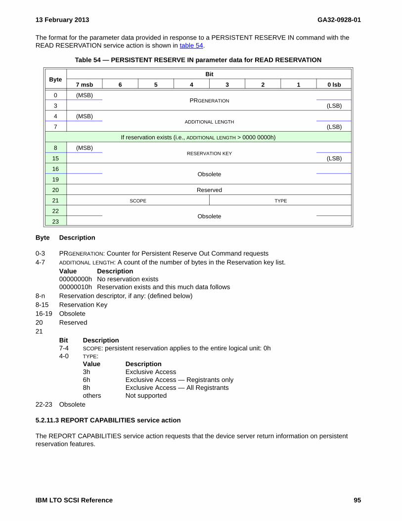
13 February 2013 GA32-0928-01
The format for the parameter data provided in response to a PERSISTENT RESERVE IN command with the READ RESERVATION service action is shown in table 54.
Byte Description
0-3 PRGENERATION: Counter for Persistent Reserve Out Command requests4-7 ADDITIONAL LENGTH: A count of the number of bytes in the Reservation key list.
Value Description00000000h No reservation exists00000010h Reservation exists and this much data follows
8-n Reservation descriptor, if any: (defined below)8-15 Reservation Key16-19 Obsolete20 Reserved21
Bit Description7-4 SCOPE: persistent reservation applies to the entire logical unit: 0h4-0 TYPE:
Value Description3h Exclusive Access6h Exclusive Access — Registrants only8h Exclusive Access — All Registrantsothers Not supported
22-23 Obsolete
5.2.11.3 REPORT CAPABILITIES service action
The REPORT CAPABILITIES service action requests that the device server return information on persistent reservation features.
Table 54 — PERSISTENT RESERVE IN parameter data for READ RESERVATION
ByteBit
7 msb 6 5 4 3 2 1 0 lsb
0 (MSB)PRGENERATION
3 (LSB)
4 (MSB)ADDITIONAL LENGTH
7 (LSB)
If reservation exists (i.e., ADDITIONAL LENGTH > 0000 0000h)
8 (MSB)RESERVATION KEY
15 (LSB)
16Obsolete
19
20 Reserved
21 SCOPE TYPE
22Obsolete
23
IBM LTO SCSI Reference 95

GA32-0928-01 13 February 2013
The format for the parameter data provided in response to a PERSISTENT RESERVE IN command with the REPORT CAPABILITIES service action is shown in table 55.
Byte Description
0-1 LENGTH: 0008h2
Bit Description7-5 Reserved4 CRH (Compatible Reservation Handling): 1b3 SIP_C (Specify Initiator Ports Capable): 1b2 ATP_C (All Target Ports Capable): 1b1 Reserved0 PTPL_C (Persist Through Power Loss Capable): 0b
3Bit Description7 TMV (Type Mask Valid): 1b6-4 ALLOW COMMANDS: 000b
Value Description000b No information is provided about whether certain commands are allowed through
certain types of persistent reservations.001b-100b Not Supported. TUR is allowed through Exclusive Access reservations [and info
about certain other commands and Write Exclusive reservations].101b-111b Reserved
3-1 Reserved0 PTPL_A (Persist Through Power Loss Activated): 0b
4 Persistent Reservation Type Mask (byte 4)Bit Description7 WR_EX_AR (Write Exclusive — All Registrants): 0b6 EX_AC_RO (Exclusive Access — Registrants Only): 1b5 WR_EX_RO (Write Exclusive — Registrants Only): 0b4 Reserved3 EX_AC (Exclusive Access): 1b2 Reserved1 WR_EX (Write Exclusive): 0b0 Reserved
Table 55 — PERSISTENT RESERVE IN parameter data for REPORT CAPABILITIES
ByteBit
7 msb 6 5 4 3 2 1 0 lsb
0 (MSB)LENGTH (0008h)
1 (LSB)
2 Reserved CRH SIP_C ATP_C Reserved PTPL_C
3 TMV ALLOW COMMANDS (000b) Reserved PTPL_A
Persistent Reservation Type Mask
4 WR_EX_AR EX_AC_RO WR_EX_RO Rsvd EX_AC Rsvd WR_EX Rsvd
5 Reserved EX_AC_AR
6Reserved
7
96 IBM LTO SCSI Reference

13 February 2013 GA32-0928-01
5 Persistent Reservation Type Mask (byte 5)Bit Description7-1 Reserved0 EX_AC_AR (Exclusive Access — All Registrants): 1b
6-7 Reserved
5.2.11.4 READ FULL STATUS service action
The READ FULL STATUS service action requests that the device server return a parameter list describing the registration and persistent reservation status of each currently registered I_T nexus for the logical unit.
The format for the parameter data provided in response to a PERSISTENT RESERVE IN command with the READ FULL STATUS service action is shown in table 56.
Byte Description
0-3 PRGENERATION: 4-7 ADDITIONAL LENGTH (n-7)8-n Full status descriptors (see 5.2.11.4.1).
Table 56 — PERSISTENT RESERVE IN parameter data for READ FULL STATUS
ByteBit
7 msb 6 5 4 3 2 1 0 lsb
0 (MSB)PRGENERATION
3 (LSB)
4 (MSB)ADDITIONAL LENGTH (n-7)
7 (LSB)
Full status descriptors
8Full status descriptor [first] (see table 57)
…
Full status descriptor [last] (see table 57)n
IBM LTO SCSI Reference 97

GA32-0928-01 13 February 2013
5.2.11.4.1 Full status descriptors
The format of the full status descriptors is shown in table 57. Each full status descriptor describes one or more registered I_T nexuses. The device returns persistent reservations status information for every registered I_T nexus.
Byte Description
0-7 RESERVATION KEY: 8-11 Reserved12
Bit Description7-2 Reserved1 ALL_TG_PT (All Target Ports)0 R_HOLDER (Reservation Holder)
13Bit Description7-4 SCOPE
3-0 TYPE
14-17 Reserved18-19 RELATIVE TARGET PORT IDENTIFIER: 20-23 ADDITIONAL DESCRIPTOR LENGTH (n-23)24-n TRANSPORTID: TransportID identifying the initiator port that is part of the I_T nexus or I_T nexuses
described by this full status descriptor.
Table 57 — PERSISTENT RESERVE IN full status descriptor format
ByteBit
7 msb 6 5 4 3 2 1 0 lsb
0 (MSB)RESERVATION KEY
7 (LSB)
8Reserved
11
12 Reserved ALL_TG_PT R_HOLDER
13 SCOPE TYPE
14Reserved
17
18 (MSB)RELATIVE TARGET PORT IDENTIFIER
19 (LSB)
20 (MSB)ADDITIONAL DESCRIPTOR LENGTH (n-23)
23 (LSB)
24TRANSPORTID
n
98 IBM LTO SCSI Reference

13 February 2013 GA32-0928-01
5.2.12 PERSISTENT RESERVE OUT - 5Fh
The Persistent Reserve Out command is defined in SPC-4 (see the latest version at http://www.t10.org/drafts.htm#SCSI3_CMNDSETS). This clause decribes the specific implementation.
The following parameters apply:
• SERVICE ACTION:Value Description00h REGISTER: Register a reservation key with the device server01h RESERVE: Create a persistent reservation using a reservation key02h RELEASE: Release a persistent reservation03h CLEAR: Clear all reservation keys and all persistent reservations04h PREEMPT: Preempt persistent reservations and/or removes registrations05h PREEMPT AND ABORT: Preempt persistent reservations and/or removes registrations
and clear the task set for the preempted initiator07h REGISTER AND MOVE: Register And Move the registration to another I_T nexus.08h-1Fh Reserved
• SCOPE: 0h
If the Service Action field is set to RESERVE, RELEASE, PREEMPT, PREEMPT AND ABORT, or REGISTER AND MOVE then SCOPE shall be zero. This field is ignored for other Service Actions.
• TYPE:Value Description3h Exclusive Access6h Exclusive Access — Registrants onlyothers Not supported
• PARAMETER LIST LENGTH: Value Description0018h All values of SERVICE ACTION except REGISTER AND MOVE (i.e., 07h)variable SERVICE ACTION set to REGISTER AND MOVE (i.e., 07h)
Table 58 — PERSISTENT RESERVE OUT CDB
ByteBit
7 msb 6 5 4 3 2 1 0 lsb
0 OPCODE (5Fh)
1 Reserved SERVICE ACTION
2 SCOPE TYPE
3Reserved
6
7 (MSB)PARAMETER LIST LENGTH
8 (LSB)
9 Control Byte (see 5.1.2.3)
IBM LTO SCSI Reference 99

GA32-0928-01 13 February 2013
5.2.12.1 Basic PERSISTENT RESERVE OUT parameter list
The PERSISTENT RESERVE OUT command with any service action except the REGISTER AND MOVE service action uses the parameter list format shown in table 59.
Byte Description
0-7 RESERVATION KEY
8-15 SERVICE ACTION RESERVATION KEY
16-19 Obsolete20
Bit Description7-4 Reserved3 SPEC_I_PT(Specify Initiator Ports): 0b2 ALL_TG_PT(All Target Ports): 0b1 Reserved0 APTPL (Activate Persist Through Power Loss): 0b
21 Reserved22-23 Obsolete
Table 59 — PERSISTENT RESERVE OUT parameter list
ByteBit
7 msb 6 5 4 3 2 1 0 lsb
0 (MSB)RESERVATION KEY
7 (LSB)
8 (MSB)SERVICE ACTION RESERVATION KEY
15 (LSB)
16Obsolete
19
20 Reserved SPEC_I_PT ALL_TG_PT Reserved APTPL
21 Reserved
22Obsolete
23
100 IBM LTO SCSI Reference

13 February 2013 GA32-0928-01
5.2.12.2 PERSISTENT RESERVE OUT command with REGISTER AND MOVE service action parameters
The parameter list format shown in table 60 shall be used by the PERSISTENT RESERVE OUT command with REGISTER AND MOVE service action.
Byte Description
0-7 RESERVATION KEY
8-15 SERVICE ACTION RESERVATION KEY
16 Reserved17
Bit Description7-2 Reserved1 UNREG (Unregister): 0 APTPL (Activate Persist Through Power Loss): 0b
18-19 RELATIVE TARGET PORT IDENTIFIER
20-23 ADDITIONAL DESCRIPTOR LENGTH (n-23)24-n TRANSPORTID
Table 60 — PERSISTENT RESERVE OUT with REGISTER AND MOVE service action parameter list
ByteBit
7 msb 6 5 4 3 2 1 0 lsb
0 (MSB)RESERVATION KEY
7 (LSB)
8 (MSB)SERVICE ACTION RESERVATION KEY
15 (LSB)
16 Reserved
17 Reserved UNREG APTPL
18 (MSB)RELATIVE TARGET PORT IDENTIFIER
19 (LSB)
20 (MSB)TRANSPORTID PARAMETER DATA LENGTH (n-23)
23 (LSB)
24TRANSPORTID
n
IBM LTO SCSI Reference 101

GA32-0928-01 13 February 2013
5.2.13 PREVENT ALLOW MEDIUM REMOVAL - 1Eh
The PREVENT ALLOW MEDIUM REMOVAL command is defined in SSC-3 (see the latest version at http://www.t10.org/drafts.htm#SCSI3_CMNDSETS). This clause decribes the specific implementation.
The Prevent Allow Medium Removal command is supported only for the Prevent Cartridge Removal option. Table 61 shows the command format.
The following parameters apply:
• PREVENT:Value Description00b Allow Cartridge Removal: Medium removal is allowed through this I_T nexus01b Prevent Cartridge Removal: Medium removal is prevented through this I_T nexus10b Obsolete11b Obsolete
5.2.13.1 Medium removal
When medium removal is prevented for an I_T nexus requests to eject or unmount the volume via a SCSI LOAD UNLOAD commands through that I_T nexus are rejected with a CHECK CONDITION status with the Sense Key set to ILLEGAL REQUEST and the additional sense code set to MEDIUM REMOVAL PREVENTED (5/5302).
When medium removal is prevented for any I_T nexus, requests to eject the volume via the panel are ignored.
Volume removal is enabled again when each I_T nexus that has prevented medium removal has issued the PREVENT ALLOW MEDIUM REMOVAL command with the PREVENT field set to 00b (Allow Cartridge Removal) or has experienced an I_T nexus loss event. A reset (bus device reset, reset message, or power on reset) also restores the drive to the allow removal state. In the case of the bus device reset or the reset message, the reset restores the allow state only if the reset occurs on the same port that originally set Prevent.
If a persistent reservation or registration is being preempted by a PERSISTENT RESERVE OUT command with PREEMPT AND ABORT service action, then the equivalent of a PREVENT ALLOW MEDIUM REMOVAL command with the PREVENT field set to 00b is processed for each I_T nexus associated with the persistent reservation or registrations being preempted.
NOTE 16 - The PREVENT ALLOW MEDIUM REMOVAL command also prohibits medium removal by any library commands that may be received.
Table 61 — PREVENT ALLOW MEDIUM REMOVAL CDB
ByteBit
7 msb 6 5 4 3 2 1 0 lsb
0 OPERATION CODE (1Eh)
1 Obsolete (LUN) Reserved
2Reserved
3
4 Reserved PREVENT
5 Control Byte (see 5.1.2.3)
102 IBM LTO SCSI Reference

13 February 2013 GA32-0928-01
5.2.14 READ - 08h
The READ command is defined in SSC (see the latest version at http://www.t10.org/drafts.htm#SCSI3_CMNDSETS). This clause decribes the specific implementation.
The following parameters apply:
• SILI (Suppress Incorrect Length Indicator): (see 4.8)
• FIXED (see 4.7)
• TRANSFER LENGTH (see 4.7)
General Read-Type Handling (see 4.8.1 on page 42) provides additional information.
Table 62 — READ CDB
ByteBit
7 msb 6 5 4 3 2 1 0 lsb
0 OPERATION CODE (08h)
1 Obsolete (LUN) Reserved SILI FIXED
2 MSBTRANSFER LENGTH
4 LSB
5 Control Byte (see 5.1.2.3)
IBM LTO SCSI Reference 103

GA32-0928-01 13 February 2013
5.2.15 READ ATTRIBUTE - 8Ch
The READ ATTRIBUTE command is defined in SPC-4 (see the latest version at http://www.t10.org/drafts.htm#SCSI3_CMNDSETS). This clause decribes the specific implementation. The READ ATTRIBUTE command (see table 63) allows an application client to read attribute values from medium auxiliary memory.
If the medium auxiliary memory is not accessible because there is no medium present, the READ ATTRIBUTE command shall be terminated with CHECK CONDITION status, with the sense key set to NOT READY, and the additional sense code set to MEDIUM NOT PRESENT.
If the medium is present but the medium auxiliary memory is not accessible, the READ ATTRIBUTE command shall be terminated with CHECK CONDITION status, with the sense key set to MEDIUM ERROR, and the additional sense code set to LOGICAL UNIT NOT READY, AUXILIARY MEMORY NOT ACCESSIBLE.
If the medium auxiliary memory is not operational, the READ ATTRIBUTE command shall be terminated with CHECK CONDITION status, with the sense key set to MEDIUM ERROR, and the additional sense code set to AUXILIARY MEMORY READ ERROR.
The following parameters apply:
• SERVICE ACTION: Value Description00h ATTRIBUTE VALUES: Return attribute values as specified in ATTRIBUTE VALUES
service action (see 5.2.15.1 on page 105)01h ATTRIBUTE LIST: Return a list of available attribute identifiers – identifiers that are in the
read only state or in the read/write state (see 4.17) as specified in ATTRIBUTE LIST service action (see 5.2.15.2 on page 105)
02h LOGICAL VOLUME LIST: Return a list of known logical volume numbers as defined in LOGICAL VOLUME LIST service action (see 5.2.15.3 on page 106)
03h PARTITION LIST: Return a list of known partition numbers as defined in PARTITION LIST service action (see 5.2.15.4 on page 106)
05h SUPPORTED ATTRIBUTES: Return a list of supported attribute identifiers – identifiers that are in the read only state, in the read/write state, or in the nonexistent state (see 4.17) as
Table 63 — READ ATTRIBUTE CDB
ByteBit
7 msb 6 5 4 3 2 1 0 lsb
0 OPERATION CODE (8Ch)
1 Reserved SERVICE ACTION
2Obsolete
4
5 LOGICAL VOLUME NUMBER
6 Reserved
7 PARTITION NUMBER
8 (MSB)FIRST ATTRIBUTE IDENTIFIER
9 (LSB)
10 (MSB)ALLOCATION LENGTH
13 (LSB)
14 Reserved
15 Control Byte (see 5.1.2.3)
104 IBM LTO SCSI Reference

13 February 2013 GA32-0928-01
defined in SUPPORTED ATTRIBUTES service action (see 5.2.15.5 on page 107)
• LOGICAL VOLUME NUMBER: 00h
• PARTITION NUMBER: The partition of the attribute to be accessed.
• FIRST ATTRIBUTE IDENTIFIER: The attribute identifier of the first attribute to be returned.
• ALLOCATION LENGTH: The number of bytes allowed to be returned
5.2.15.1 ATTRIBUTE VALUES service action
The READ ATTRIBUTE command with ATTRIBUTE VALUES service action returns parameter data containing the attributes that are in the read state or read/write state (see 4.17) specified by the PARTITION NUMBER, LOGICAL VOLUME NUMBER, and FIRST ATTRIBUTE IDENTIFIER fields in the CDB. The returned parameter data shall contain the requested attributes in ascending numerical order by attribute identifier value and in the format shown in table 64.
The AVAILABLE DATA field shall contain the number of bytes of attribute information in the parameter list.
Attribute format (see 6.5.1 on page 349) describes the format of the attributes.
5.2.15.2 ATTRIBUTE LIST service action
The READ ATTRIBUTE command with ATTRIBUTE LIST service action returns parameter data containing the attribute identifiers for the attributes that are in the read only state or in the read/write state (see 4.17) in the specified partition and volume number. The contents of FIRST ATTRIBUTE IDENTIFIER field in the CDB shall be ignored. The returned parameter data shall contain the requested attribute identifiers in ascending numerical order by attribute identifier value and in the format shown in table 65.
Table 64 — READ ATTRIBUTE with ATTRIBUTE VALUES service action parameter list format
ByteBit
7 msb 6 5 4 3 2 1 0 lsb
0 (MSB)AVAILABLE DATA (n-3)
3 (LSB)
Attribute(s)
4Attribute 0 (see 6.5.1)
…
Attribute x (see 6.5.1)n
Table 65 — READ ATTRIBUTE with ATTRIBUTE LIST service action parameter list format
ByteBit
7 msb 6 5 4 3 2 1 0 lsb
0 (MSB)AVAILABLE DATA (n-3)
3 (LSB)
Attribute identifiers
4ATTRIBUTE IDENTIFIER 0
5
…
n-1ATTRIBUTE IDENTIFIER x
n
IBM LTO SCSI Reference 105

GA32-0928-01 13 February 2013
The AVAILABLE DATA field shall contain the number of bytes of attribute identifiers in the parameter list.
An ATTRIBUTE IDENTIFIER field is returned for each attribute that is in the read only state or in the read/write state (see 4.17) in the specified partition and volume number. Attribute identifier values (see 6.5.2 on page 350) provides a description of the attribute identifier values.
5.2.15.3 LOGICAL VOLUME LIST service action
The READ ATTRIBUTE command with LOGICAL VOLUME LIST service action returns parameter data (see table 66) identifying the supported number of logical volumes. The contents of LOGICAL VOLUME NUMBER, PARTITION NUMBER, and FIRST ATTRIBUTE IDENTIFIER fields in the CDB shall be ignored.
The AVAILABLE DATA field shall contain two.
The FIRST LOGICAL VOLUME NUMBER field indicates the first volume available. Logical volume numbering should start at zero.
The NUMBER OF LOGICAL VOLUMES AVAILABLE field indicates the number of volumes available.
5.2.15.4 PARTITION LIST service action
The READ ATTRIBUTE command with PARTITION LIST service action returns parameter data (see table 67) identifying the number of partitions supported in the specified logical volume number. The contents of PARTITION NUMBER and FIRST ATTRIBUTE IDENTIFIER fields in the CDB shall be ignored.
The AVAILABLE DATA field shall contain two.
The FIRST PARTITION NUMBER field indicates the first partition available on the specified logical volume number. Partition numbering should start at zero.
The NUMBER OF PARTITIONS AVAILABLE field indicates the number of partitions available on the specified logical volume number.
Table 66 — READ ATTRIBUTE with LOGICAL VOLUME LIST service action parameter list format
ByteBit
7 msb 6 5 4 3 2 1 0 lsb
0 (MSB)AVAILABLE DATA (0002h)
1 (LSB)
2 FIRST LOGICAL VOLUME NUMBER
3 NUMBER OF LOGICAL VOLUMES AVAILABLE
Table 67 — READ ATTRIBUTE with PARTITION LIST service action parameter list format
ByteBit
7 msb 6 5 4 3 2 1 0 lsb
0 (MSB)AVAILABLE DATA (0002h)
1 (LSB)
2 FIRST PARTITION NUMBER
3 NUMBER OF PARTITIONS AVAILABLE
106 IBM LTO SCSI Reference

13 February 2013 GA32-0928-01
5.2.15.5 SUPPORTED ATTRIBUTES service action
The READ ATTRIBUTE command with SUPPORTED ATTRIBUTES service action returns parameter data containing the attribute identifiers for the attributes that are in the read only state, in the read/write state, or in the nonexistent state (see 4.17) in the specified partition and volume number. The contents of FIRST ATTRIBUTE IDENTIFIER field in the CDB shall be ignored. The returned parameter data shall contain the requested attribute identifiers in ascending numerical order by attribute identifier value and in the format shown in table 68.
The AVAILABLE DATA field shall contain the number of bytes of attribute identifiers in the parameter list.
An ATTRIBUTE IDENTIFIER field is returned for each attribute that is in the read only state, in the read/write state, or in the nonexistent state (see 4.17) in the specified partition and volume number. Attribute identifier values (see 6.5.2 on page 350) describes the attribute identifier values.
Table 68 — READ ATTRIBUTE with SUPPORTED ATTRIBUTES service action parameter list format
ByteBit
7 msb 6 5 4 3 2 1 0 lsb
0 (MSB)AVAILABLE DATA (n-3)
3 (LSB)
Attribute identifiers
4ATTRIBUTE IDENTIFIER 0
5
…n-1
ATTRIBUTE IDENTIFIER xn
IBM LTO SCSI Reference 107

GA32-0928-01 13 February 2013
5.2.16 READ BLOCK LIMITS - 05h
The READ BLOCK LIMITS command is defined in SSC (see the latest version at http://www.t10.org/drafts.htm#SCSI3_CMNDSETS). This clause decribes the specific implementation.
The following parameters apply:
• maximum logical object identifier (MLOI):Value Description0b Return the READ BLOCK LIMITS block length data (see 5.2.16.1).1b Return the READ BLOCK LIMITS maximum logical object identifier data (see 5.2.16.2).
5.2.16.1 READ BLOCK LIMITS block length data
The returned parameter data is in the format shown in table 70.
The following parameters apply to the Read Block Limits data:
Byte Description
0Bit Description7-5 Reserved4-0 GRANULARITY: The supported block size granularity. The device supports all block sizes n such
that n minus the MINIMUM BLOCK LENGTH LIMIT is a multiple of 2GRANULARITY and n is greater than or equal to the MINIMUM BLOCK LENGTH LIMIT and less than or equal to the MAXIMUM BLOCK LENGTH LIMIT.
1-3 MAXIMUM BLOCK LENGTH LIMIT: 80 0000h (8,388,608 bytes) block length limit length limits4-5 MINIMUM BLOCK LENGTH LIMIT: 0001h (1 byte) minimum block length limit
Any block length in the range of MINIMUM BLOCK LENGTH LIMIT to MAXIMUM BLOCK LENGTH LIMIT is supported.
NOTE 17 - The value reported in the MAXIMUM BLOCK LENGTH LIMIT field is the maximum block length when there is at least one encrypted logical block on the volume. When there are no encrypted logical blocks on the volume
Table 69 — READ BLOCK LIMITS CDB
ByteBit
7 msb 6 5 4 3 2 1 0 lsb
0 OPERATION CODE (05h)
1 Obsolete (LUN) Reserved MLOI
2Reserved
4
5 Control Byte (see 5.1.2.3)
Table 70 — RBL parameter data
ByteBit
7 msb 6 5 4 3 2 1 0 lsb
0 Reserved GRANULARITY
1 (MSB)MAXIMUM BLOCK LENGTH LIMIT
3 (LSB)
4 (MSB)MINIMUM BLOCK LENGTH LIMIT
5 (LSB)
108 IBM LTO SCSI Reference

13 February 2013 GA32-0928-01
a larger block length is allowed but not reported. This difference in maximum block length allowed has the potential to create confusion. Because of that, it is recommended that users limit their maximum block length to the values reported.
Data Transfer, Block Limits, and Fixed Block Option (see 4.7 on page 41) provides further explanation.
5.2.16.2 READ BLOCK LIMITS maximum logical object identifier data
The READ BLOCK LIMITS maximum logical object identifier data (see table 71) specifies the maximum value ofthe logical object identifier the logical unit supports.
The following parameters apply to the Read Block Limits maximum logical object identifier data:
Byte Description
0-11 Reserved12-19 MAXIMUM LOGICAL OBJECT IDENTIFIER: The maximum value the device server supports in a logical object
identifier field. This field is set to 0000_0000_FFFF_FFFFh.
NOTE 18 - The drive establishes early warning at a constant number of blocks prior to the MAXIMUM LOGICAL OBJECT IDENTIFIER. At the time this document was published, the drive assumes a block size of 32 KiB for these calculations, but this may change at any time. Additionally, programmable early warning, if configured, is returned prior to the early warning value using an assumed block size of 32 KiB.
Table 71 — READ BLOCK LIMITS maximum logical object identifier data
ByteBit
7 msb 6 5 4 3 2 1 0 lsb
0
Reserved…
11
12 (MSB)
MAXIMUM LOGICAL OBJECT IDENTIFIER…
19 (LSB)
IBM LTO SCSI Reference 109

GA32-0928-01 13 February 2013
5.2.17 READ BUFFER - 3Ch
The Read Buffer command is defined in SPC (see the latest version at http://www.t10.org/drafts.htm#SCSI3_CMNDSETS). This clause describes the specific implementation.
The following parameters apply:
• MODE:Value – DescriptionMODE[00h] – Combined header and data (see 5.2.17.1 on page 111)MODE[02h] – Data (see 5.2.17.2 on page 111)MODE[03h] – Descriptor (see 5.2.17.3 on page 111)MODE[07h] – Descriptor with algorithmic offset boundary (see 5.2.17.4 on page 112)MODE[0Ah] – Read data from echo buffer (see 5.2.17.5 on page 112)MODE[0Bh] – Echo buffer descriptor (see 5.2.17.6 on page 113)MODE[1Ch] – Error history (see 5.2.17.7 on page 113)
• BUFFER ID: The supported buffers are described in Supported Buffers for modes other than 1Ch (see 6.7.1 on page 425).
• BUFFER OFFSET: In mode 02h, this is the starting address in the buffer to be read. For mode 03h, this field must be 000000h.
NOTE 19 - If the BUFFER OFFSET is not on the boundary specified in 5.2.17.3 on page 111 or 5.2.17.4 on page 112, then the device returns CHECK CONDITION status with associated sense data of 5/2400 (Illegal Request, Invalid Field in CDB).
• ALLOCATION LENGTH: The maximum number of bytes to be transferred starting at the offset specified in BUFFER OFFSET.
The device transfers the number of bytes specified in the ALLOCATION LENGTH field or the number of bytes in the header or buffer being read, whichever is less. This is not an error. The host may use MODE 03h to query the amount of data in the specified buffer prior to reading such data with MODE 02h.
Each buffer image has its own unique format, describing where certain key data may be found. Certain buffers contain embedded data in the buffer image describing the length of the total buffer image, and a CRC field that checks the total buffer image. Uploading the microcode buffer is one such example.
Supported Buffers for modes other than 1Ch (see 6.7.1 on page 425) describes the supported Buffer ID’s.
Table 72 — READ BUFFER CDB
ByteBit
7 msb 6 5 4 3 2 1 0 lsb
0 OPERATION CODE (3Ch)
1 Obsolete (LUN) MODE
2 BUFFER ID
3 (MSB)BUFFER OFFSET
5 (LSB)
6 (MSB)ALLOCATION LENGTH
8 (LSB)
9 Control Byte (see 5.1.2.3)
110 IBM LTO SCSI Reference

13 February 2013 GA32-0928-01
5.2.17.1 MODE[00h] – Combined header and data
In this mode, a four-byte header followed by data bytes is returned to the application client in the Data-In Buffer.The allocation length should be set to four or greater. The BUFFER ID and the BUFFER OFFSET fields are reserved.
The four-byte READ BUFFER header (see table 73) is followed by data bytes from the buffer.
The following parameters apply:
Byte Description
0 Reserved1-3 BUFFER CAPACITY: The total number of data bytes available in the buffer.4-n Data: Data from the buffer specified by the BUFFER ID field.
5.2.17.2 MODE[02h] – Data
In this mode, the Data-In Buffer is filled only with logical unit buffer data. The BUFFER ID field of the command CDB specifies a buffer within the logical unit from which data shall be transferred.
The BUFFER OFFSET field of the command CDB contains the byte offset within the specified buffer from which data shall be transferred. The application client should conform to the offset boundary requirements returned in the READ BUFFER descriptors (MODE[03h] – Descriptor (see 5.2.17.3 on page 111) or MODE[07h] – Descriptor with algorithmic offset boundary (see 5.2.17.4 on page 112)). If the device server is unable to accept the specified buffer offset, the command shall be terminated with CHECK CONDITION status, with the sense key set to ILLEGAL REQUEST, and the additional sense code set to INVALID FIELD IN CDB.
5.2.17.3 MODE[03h] – Descriptor
In this mode, a maximum of four bytes of READ BUFFER descriptor information is returned. The BUFFER OFFSET field is reserved in this mode. The allocation length should be set to four or greater. The READ BUFFER descriptor is defined as shown in table 74.
Table 73 — READ BUFFER header
ByteBit
7 msb 6 5 4 3 2 1 0 lsb
0 Reserved
1 (MSB)BUFFER CAPACITY
3 (LSB)
4Data
n
Table 74 — READ BUFFER descriptor
ByteBit
7 msb 6 5 4 3 2 1 0 lsb
0 OFFSET BOUNDARY
1 (MSB)BUFFER CAPACITY
3 (LSB)
IBM LTO SCSI Reference 111

GA32-0928-01 13 February 2013
The following parameters apply:
Byte Description
0 OFFSET BOUNDARY: For READ BUFFER commands, the OFFSET BOUNDARY field MODE[03h] – Descriptor (see 5.2.17.3 onpage 111) applies to the following modes:
a) data (i.e., 02h) (see 5.2.17.2); andb) error history (i.e., 1Ch) which is not supported.
For WRITE BUFFER commands, the OFFSET BOUNDARY field MODE[03h] – Descriptor (see 5.2.17.3 onpage 111) applies to the following modes:
a) MODE[02h] – Data (see 5.2.41.2 on page 179);b) download microcode with offsets and activate (i.e., 06h) MODE[06h] – Download microcode with
offsets and activate (see 5.2.41.5 on page 179); andc) download microcode with offsets, save, and activate (i.e., 07h) MODE[07h] – Download
microcode with offsets, save, and activate (see 5.2.41.6 on page 180).For data mode (i.e., 02h), the boundary alignment indicated by the OFFSET BOUNDARY field applies only tothe buffer specified by the BUFFER ID field. For modes other than data to which the OFFSET BOUNDARY fieldapplies, the boundary alignment applies regardless of the buffer specified by the BUFFER ID field.Value Descriptionothers Multiples of 2code (e.g., 00h means multiples of 1 byte or no offset restrictions, 01h means multiples of 2
bytes or even offsets, 02h means multiples of 4 bytes)FFh 000000h is the only supported buffer offset
1-3 BUFFER CAPACITY: The maximum size in bytes of the buffer specified by the BUFFER ID field for the:a) READ BUFFER command with data mode (i.e., 02h); andb) WRITE BUFFER command with data mode (i.e., 02h).
5.2.17.4 MODE[07h] – Descriptor with algorithmic offset boundary
For buffers where the size does not fit into the BUFFER OFFSET field and the BUFFER CAPACITY fields (see table 74) the BUFFER OFFSET field and the BUFFER CAPACITY fields are interpreted for buffer modes 00h, 01h, 02h, 03h, and 07h as follows:
Value Description00h to 7Fh Multiples of 64 bytes (i.e., the value is left shifted by 6 bits)80h to FEh Left shifted by n where n is the value returned in the Offset Boundary field using the
equation 80h | n (e.g., 86h indicates shift value left by 6 bits)FFh 000000h is the only supported buffer offset
5.2.17.5 MODE[0Ah] – Read data from echo buffer
In this mode the device server transfers data to the application client from the echo buffer that was written by the most recent WRITE BUFFER command with the MODE field set to write data to echo buffer (see 5.2.41.7) received on the same I_T_L nexus.
The BUFFER ID and BUFFER OFFSET fields are ignored in this mode.
If no WRITE BUFFER command with the mode set to write data to echo buffer received on this I_T_L nexus has completed without an error, then the READ BUFFER command terminates with CHECK CONDITION status, with the sense key set to ILLEGAL REQUEST, and the additional sense code set to COMMAND SEQUENCE ERROR. If the data in the echo buffer has been overwritten by another I_T_L nexus, then the READ BUFFER command is terminated with CHECK CONDITION status, with the sense key set to ABORTED COMMAND, and the additional sense code set to ECHO BUFFER OVERWRITTEN.
112 IBM LTO SCSI Reference

13 February 2013 GA32-0928-01
5.2.17.6 MODE[0Bh] – Echo buffer descriptor
In this mode, a maximum of four bytes of READ BUFFER descriptor information is returned. The device server returns the descriptor information for the echo buffer. The BUFFER ID field and BUFFER OFFSET field are reserved in this mode. The allocation length should be set to four or greater. The READ BUFFER descriptor is defined as shown in table 75.
The following parameters apply:
Byte Description
0Bit Description7-1 Reserved0 EBOS (echo buffer overwritten supported): 1b
1 Reserved2-3
Bit Description7-5;B2 Reserved4-0;B2+7-0;B3 BUFFER CAPACITY: The size of the echo buffer in bytes aligned to a four-byte boundary. The max-
imum echo buffer size is 4 096 bytes.
5.2.17.7 MODE[1Ch] – Error history
5.2.17.7.1 Error history overview
This mode is used to manage and retrieve error history (see 4.20).
If the device is unable to process a READ BUFFER command with the MODE field set to 1Ch, then the device terminates the READ BUFFER command with CHECK CONDITION status, with the sense key set to ILLEGAL REQUEST, and the additional sense code set to COMMAND SEQUENCE ERROR.
Table 75 — Echo buffer descriptor
ByteBit
7 msb 6 5 4 3 2 1 0 lsb
0 Reserved EBOS
1 Reserved
2 Reserved (MSB)
3 BUFFER CAPACITY (LSB)
IBM LTO SCSI Reference 113

GA32-0928-01 13 February 2013
The BUFFER ID field (see table 76) specifies the action that the device performs, and the parameter data, if any, that the device returns.
The command is terminated with CHECK CONDITION status with the sense key set to ILLEGAL REQUEST and the additional sense code set to OPERATION IN PROGRESS if the device receives a READ BUFFER command:
a) with the MODE field set to 1Ch;b) with the BUFFER ID field set to a value that table 76 shows as constrained by error history I_T_L nexus;c) if an error history I_T_L nexus exists and the command is received from an I_T_L nexus that is different
than that I_T_L nexus; andd) an error history snapshot exists.
The BUFFER OFFSET field specifies the byte offset from the start of the buffer specified by the BUFFER ID field from which the device returns data. The application client should conform to the offset boundary requirements indicated in the READ BUFFER descriptor (see 5.2.17.3). If the buffer offset is not one of those shown in table 76 or the device is unable to accept the specified buffer offset, then the device terminates the READ BUFFER command with CHECK CONDITION status, with the sense key set to ILLEGAL REQUEST, and the additional sense code set to INVALID FIELD IN CDB.
Table 76 — Error history BUFFER ID field
Code DescriptionBuffer offset
Error historyI_T nexus
constrained Reference
00h Return error history directory 0000h Yes 5.2.17.7.2
01h Return error history directory and create new error history snapshot
0000h Yes 5.2.17.7.2
02h Return error history directory and establish new error history I_T_L nexus
0000h No 5.2.17.7.2
03h Return error history directory, establish new error history I_T_L nexus, and create new error history snapshot
0000h No 5.2.17.7.2
04h to 0Fh Reserved Yes
10h to EFh Return error history 0000h to FFFFh
Yes 5.2.17.7.3
10h Return current error history snapshot: A drive dump created at the most recent snapshot event (i.e. snapshot –no embed-ded dumps).
5.2.17.7.3.1
20h Return emergency dump (e.g., a dump copied to flash by copy to flash request)
5.2.17.7.3.2
21h to 28h Return prioritized dump in flash (i.e., 21h is the highest priority and 28h is the low-est priority)
5.2.17.7.3.3
29h to EEh Reserved for future error histories
EFh Return error history names list 5.2.17.7.3.4
F0h to FDh Reserved Yes
FEh Clear error history I_T_L nexus Ignored Yes 5.2.17.7.4
FFh Clear error history I_T_L nexus and release error history snapshot
Ignored Yes 5.2.17.7.5
114 IBM LTO SCSI Reference

13 February 2013 GA32-0928-01
5.2.17.7.2 MODE[1Ch] 00h to 03h: Error history directory
Whenever allowed by established error history I_T_L nexus constraints (see 5.2.17.7.1), if any, all error history device actions return an error history directory (see table 78). Some error history device actions also discard the existing error history snapshot and create a new error history snapshot (see table 77).
The error history directory is defined in table 78.
Table 77 — Summary of error history directory device actions
BUFFER ID field
Establish new error history I_T_L nexus
Error history snapshot
Preserved (if exists) Created
00h No a Yes No b
01h No a No Yes
02h Yes Yes No b
03h Yes No Yes
a If no error history I_T_L nexus is established, a new one is established.
b If no error history snapshot exists, a new one is created.
Table 78 — Error history directory
BitByte
7 6 5 4 3 2 1 0
0 (MSB)T10 VENDOR IDENTIFICATION
•••
7 (LSB)
8 VERSION
9 Reserved EHS_RETRIEVED EHS_SOURCE CLR_SUP
10Reserved
•••
29
30 (MSB)DIRECTORY LENGTH (n-31)
31 (LSB)
Error history directory list
32Error history directory entry [first]
(see table 79)
•••
39
•••
n-7Error history directory entry [last]
(see table 79)•••
n
IBM LTO SCSI Reference 115

GA32-0928-01 13 February 2013
The following parameters apply:
Byte Description
0-7 T10 VENDOR IDENTIFICATION: “IBM “8 VERSION: 01h9
Bit Description7-5 Reserved4-3 EHS_RETRIEVED (error history retrieved): indicates whether a clear error history device action has
been requested for the error history snapshot. EHS_RETRIEVED field is set to 10b when the error history snapshot is created.Value Description00b No information01b The error history I_T_L nexus has requested buffer ID FEh (i.e., clear error his-
tory I_T_L nexus) or buffer ID FFh (i.e., clear error history I_T_L nexus and release snapshot) for the current error history snapshot.
10b An error history I_T_L nexus has not requested buffer ID FEh (i.e., clear error his-tory I_T_L nexus) or buffer ID FFh (i.e., clear error history I_T_L nexus and release snapshot) for the current error history snapshot.
11b Reserved2-1 EHS_SOURCE (error history source): indicates the source of the error history snapshot.
Value Description00b The error history snapshot was created by the device and was not created due to
processing a READ BUFFER command.01b Error history snapshot was created due to processing of the current READ BUF-
FER command10b Error history snapshot was created due to processing of a previous READ BUF-
FER command11b Reserved
0 CLR_SUP (clear support): 0b10-29 Reserved30-31 DIRECTORY LENGTH: indicates the number of bytes that follow in the error history directory list.32-n Error history directory list: contains an error history directory entry (see table 79) for each supported
buffer ID in the range of 00h to EFh. The first entry is for buffer ID 00h and the other entries are in orderof ascending buffer IDs. The supported buffer IDs are not necessarily contiguous.
5.2.17.7.2.1 Error history directory entry
An error history directory entry contains information about a buffer that is available to be read with the error history mode. One or more error history directory entries are listed in the error history directory list. The error history directory entry is defined in table 79.
Table 79 — Error history directory entry
BitByte
7 6 5 4 3 2 1 0
0 SUPPORTED BUFFER ID
1Reserved
•••
3
4 (MSB)MAXIMUM AVAILABLE LENGTH
•••
7 (LSB)
116 IBM LTO SCSI Reference

13 February 2013 GA32-0928-01
The following parameters apply:
Byte Description
0 SUPPORTED BUFFER ID: indicates the error history buffer ID associated with this entry.1-3 Reserved.4-7 MAXIMUM AVAILABLE LENGTH: indicates the current size of the data available for transfer from the buffer
indicated in the SUPPORTED BUFFER ID field (i.e., the actual size of the data).
5.2.17.7.3 MODE[1Ch] 10h to FEh: Error history data buffer
Unless an error is encountered, the device returns parameter data that contains the error history from the error history snapshot from the specified buffer at the specified buffer offset.
If the device receives a READ BUFFER command with the MODE field set to 1Ch from the established error history I_T_L nexus and the BUFFER ID field is set to a value that the error history directory (see 5.2.17.7.2) shows as not supported, then the command is terminated with CHECK CONDITION status with the sense key set to ILLEGAL REQUEST and the additional sense code set to INVALID FIELD IN CDB.
If the value in the BUFFER OFFSET field is not supported, the command is terminated with CHECK CONDITION status with the sense key set to ILLEGAL REQUEST and the additional sense code set to INVALID FIELD IN CDB.
The amount of error history in the specified buffer is less than or equal to the number of bytes indicated by the MAXIMUM AVAILABLE LENGTH field in the error history directory (see 5.2.17.7.2).
5.2.17.7.3.1 MODE[1Ch] 10h: Current error history snapshot
The current error history snapshot is a dump that was written to non-volatile memory using Send Diagnostic Write Dump to FLASH (Diag 0162) or that was written by internal algorithms. This buffer may or may not exist.
5.2.17.7.3.2 MODE[1Ch] 20h: Emergency dump
The emergency dump is a dump that was written to non-volatile memory using Send Diagnostic Write Dump to FLASH (Diag 0162) or written by internal algorithms. This buffer may or may not exist.
5.2.17.7.3.3 MODE[1Ch] 21h to 28h: Prioritized flash dump
The prioritized flash dumps are written to non-volatile memory and prioritized by internal algorithms that are designed to provide the optimum data capture for debug. The highest priority buffer is 21h and the lowest priority buffer is 28h. These buffers may or may not exist.
IBM LTO SCSI Reference 117

GA32-0928-01 13 February 2013
5.2.17.7.3.4 MODE[1Ch] EFh: Error history names list
The error history names list buffer(i.e., Buffer ID EFh) contains a list of error history buffer ID’s and their associated names. The error history names list is defined in table 80.
The following parameters apply:
Byte Description
0-1 NAMES LIST LENGTH: indicates the number of bytes that follow in the error history names list.2-n Error history names list: contains an error history names entry (see table 81) for each supported buffer.
An entry in this list does not mean that there is any data currently available in the buffer.
5.2.17.7.3.4.1 Error history names entry
An error history names entry contains the buffer ID and name associated with an error history buffer. The error history names entry is defined in table 81.
The following parameters apply:
Byte Description
0 SUPPORTED BUFFER ID: indicates the error history buffer ID associated with this entry.1-3 Reserved.
Table 80 — MODE[1Ch] EFh: Error history names list format
BitByte
7 6 5 4 3 2 1 0
0 (MSB)NAMES LIST LENGTH (n-1)
1 (LSB)
Error history names list
2Error history names entry [first]
(see table 81)
•••
37
•••
n-35Error history names entry [last]
(see table 81)•••
n
Table 81 — Error history names entry
BitByte
7 6 5 4 3 2 1 0
0 SUPPORTED BUFFER ID
1Reserved
•••
3
4 (MSB)ERROR HISTORY NAME
•••
35 (LSB)
118 IBM LTO SCSI Reference

13 February 2013 GA32-0928-01
4-35 ERROR HISTORY NAME: contains a 32 character ASCII name assigned to the error history contained in thebuffer associated with SUPPORTED BUFFER ID.
5.2.17.7.4 MODE[1Ch] FEh: Clear error history I_T_L nexus
If the BUFFER ID field is set to FEh, the device:
a) clears the error history I_T_L nexus, if any; andb) does not transfer any data.
5.2.17.7.5 MODE[1Ch] FFh: Clear error history I_T_L nexus and release snapshot
If the BUFFER ID field is set to FFh, the device:
a) clears the error history I_T_L nexus, if any,b) releases the error history snapshot, if any; andc) does not transfer any data.
IBM LTO SCSI Reference 119

GA32-0928-01 13 February 2013
5.2.18 READ DYNAMIC RUNTIME ATTRIBUTE - D1h
The READ DYNAMIC RUNTIME ATTRIBUTE command has the format in table 82.
The format of parameter data returned by the READ DYNAMIC RUNTIME ATTRIBUTE command depends on the service action specified (see 5.2.18.1).
The FIRST DYNAMIC RUNTIME ATTRIBUTE IDENTIFIER field specifies the dynamic runtime attribute identifier of the first attribute to be returned. Only attributes with a dynamic runtime attribute identifier greater than or equal to the value specified in the FIRST DYNAMIC RUNTIME ATTRIBUTE IDENTIFIER field and that are not in the nonexistent or unsupported state shall be reported. It shall not be considered an error if the specified dynamic runtime attribute is in the unsupported or nonexistent state.
The LAST DYNAMIC RUNTIME ATTRIBUTE IDENTIFIER field specifies the dynamic runtime attribute identifier of the last attribute to be returned. Only attributes with a dynamic runtime attribute identifier less than or equal to the value specified in the LAST DYNAMIC RUNTIME ATTRIBUTE IDENTIFIER field and that are not in the nonexistent or unsupported state shall be reported. It shall not be considered an error if the specified dynamic runtime attribute is in the unsupported or nonexistent state. If the attribute identifier specified in the LAST DYNAMIC RUNTIME ATTRIBUTE IDENTIFIER field is less than the attribute identifier specified in the FIRST DYNAMIC RUNTIME ATTRIBUTE IDENTIFIER field, then the command shall be terminated with CHECK CONDITION status, with the sense key set to ILLEGAL REQUEST, and the additional sense code set to INVALID FIELD IN CDB.
If the ALLOCATION LENGTH specified causes an attribute to be truncated this shall not be considered an error. All data up to the allocation length shall be returned.
Table 82 — READ DYNAMIC RUNTIME ATTRIBUTE CDB
BitByte
7 6 5 4 3 2 1 0
0 OPERATION CODE (D1h)
1 Reserved SERVICE ACTION
2FIRST DYNAMIC RUNTIME ATTRIBUTE IDENTIFIER
3
4 LAST DYNAMIC RUNTIME ATTRIBUTE IDENTIFIER
5
6 (MSB)
ALLOCATION LENGTH…
9 (LSB)
10 Reserved
11 Control
120 IBM LTO SCSI Reference

13 February 2013 GA32-0928-01
5.2.18.1 READ DYNAMIC RUNTIME ATTRIBUTE Service Action
The service actions defined for the READ DYNAMIC RUNTIME ATTRIBUTE command are shown in Table 83.
5.2.18.2 SUPPORTED ATTRIBUTES service action
The READ DYNAMIC RUNTIME ATTRIBUTE command with SUPPORTED ATTRIBUTES service action (SERVICE ACTION field set to 00h) returns parameter data containing the attribute identifiers that the device server supports. The returned parameter data shall contain the requested attribute identifiers in ascending numerical
Table 83 — READ DYNAMIC RUNTIME ATTRIBUTE Service Action codes
Code Name Description Reference
00h SUPPORTED ATTRIBUTESReturn a list of dynamic runtime attribute identifiers that the device server supports. No indication of attribute state is implied.
5.2.18.2
01h-0Fh Reserved
10hATTRIBUTE VALUES FOR THIS I_T NEXUS
Return values for:a) all logical unit type attributes;b) all target type attributes associated with the
I_T nexus through which the command was received; and
c) all initiator type attributes associated with the I_T nexus through which the command was recevied.
5.2.18.3
11hATTRIBUTE VALUES FOR ALL I_T NEXUSES
Return values for:a) all logical unit type attributes;b) all target type attributes associated with all
I_T nexuses; andc) all initiator type attributes associated with all
I_T nexuses.
5.2.18.4
12h-1Fh Reserved
IBM LTO SCSI Reference 121

GA32-0928-01 13 February 2013
order by attribute identifier and in the format shown in Table 84.
The SERVICE ACTION field shall contain the service action specified in the READ DYNAMIC RUNTIME ATTRIBUTE CDB.
The AVAILABLE DATA field shall contain the number of bytes of attribute identifiers in the parameter list. The AVAILABLE DATA field shall not be adjusted by the CDB ALLOCATION LENGTH field.
An attribute identifier is returned for each attribute that the device server supports. No indication of the current state of the reported attributes is made. See 6.1.2 for a description of the attribute identifier.
5.2.18.3 ATTRIBUTE VALUES FOR THIS I_T NEXUS service action
The READ DYNAMIC RUNTIME ATTRIBUTE command with ATTRIBUTE VALUES FOR THIS I_T NEXUS service action (i.e., the SERVICE ACTION field is set to 10h) returns parameter data containing the attributes for the I_T_L Nexus through which this command is received starting with the FIRST ATTRIBUTE IDENTIFIER field in the CDB and ending with the LAST ATTRIBUTE IDENTIFIER field in the CDB.
Table 84 — READ DYNAMIC RUNTIME ATTRIBUTE with SUPPORTED ATTRIBUTES service action parameter list format
BitByte
7 6 5 4 3 2 1 0
0 Reserved SERVICE ACTION
1
Reserved…
3
4
AVAILABLE DATA (n-7)…
7
Attribute Identifiers
8Attribute Identifier 0
9
n-1Attribute Identifier x
n
122 IBM LTO SCSI Reference

13 February 2013 GA32-0928-01
The returned parameter data shall contain the requested attributes in in the format shown in table 85 and in ascending numerical order by I_T nexus index then attribute identifier
The SERVICE ACTION field shall contain the service action specified in the READ DYNAMIC RUNTIME ATTRIBUTE CDB.
The AVAILABLE DATA field shall contain the number of bytes of attribute information in the parameter list. The value in the AVAILABLE DATA field shall not be adjusted by the CDB ALLOCATION LENGTH field.
The format of the attributes is described in 6.1.1.
5.2.18.4 ATTRIBUTE VALUES FOR ALL I_T NEXUSES service action
The READ DYNAMIC RUNTIME ATTRIBUTE command with ATTRIBUTE VALUES FOR ALL I_T NEXUSES service action (i.e., the SERVICE ACTION field set to 11h) returns parameter data containing the attributes for all known I_T nexuses and starting with the FIRST ATTRIBUTE IDENTIFIER field in the CDB and ending with the LAST ATTRIBUTE IDENTIFIER field in the CDB.
Table 85 — READ DYNAMIC RUNTIME ATTRIBUTE with ATTRIBUTE VALUES FOR THIS I_T NEXUS service action parameter list format
BitByte
7 6 5 4 3 2 1 0
0 Reserved SERVICE ACTION
1
Reserved…
3
4
AVAILABLE DATA (n-7)…
7
Attribute(s)
8
Attribute 0 (see 6.1.1)…
Attribute x (see 6.1.1)…
n
IBM LTO SCSI Reference 123

GA32-0928-01 13 February 2013
The returned parameter data shall contain the requested attribute values for all I_T nexus in ascending numerical order by I_T nexus index then attribute identifier and in the format shown in table 86.
The SERVICE ACTION field shall contain the service action specified in the READ DYNAMIC RUNTIME ATTRIBUTE CDB.
The AVAILABLE DATA field shall contain the number of bytes to follow. The value in the AVAILABLE DATA field shall not be adjusted by the CDB ALLOCATION LENGTH field.
The format of the attributes is described in 6.1.1.
Table 86 — READ DYNAMIC RUNTIME ATTRIBUTE with ATTRIBUTE VALUES FOR ALL I_T NEXUSES service action parameter list format
BitByte
7 6 5 4 3 2 1 0
0 Reserved SERVICE ACTION
1
Reserved…
3
4
AVAILABLE DATA (n-7)…
7
Attribute(s)
8
Attribute 0 (see 6.1.1)…
Attribute x (see 6.1.1)…
n
124 IBM LTO SCSI Reference

13 February 2013 GA32-0928-01
5.2.19 READ POSITION - 34h
5.2.19.1 READ POSITION command description
The Read Position command is defined in SSC (see the latest version at http://www.t10.org/drafts.htm#SCSI3_CMNDSETS). This clause decribes the specific implementation.
The READ POSITION command (see table 87) reports the current position and provides information about logical objects contained in the object buffer. No medium movement shall occur as a result of responding to the command.
The following parameters apply:
• SERVICE ACTION: Value Description00h SHORT FORM-- BLOCK ID: Device server shall return 20 bytes of data with the FIRST
LOGICAL OBJECT LOCATION and LAST LOGICAL OBJECT LOCATION fields as logical object identifier values, relative to a partition (see 5.2.19.2). The ALLOCATION LENGTH field shall be zero.
06h LONG FORM: Device server shall return 32 bytes of data (see 5.2.19.3). The ALLOCATION LENGTH field shall be zero.
08h EXTENDED FORM: Device server shall return 32 bytes of data up to the maximum length specified by the ALLOCATION LENGTH field (see 5.2.19.4).
others The command is terminated with CHECK CONDITION status with the sense key set to ILLEGAL REQUEST, and the additional sense code set to INVALID FIELD IN CDB.
• ALLOCATION LENGTH: Length of the data to return. Shall be set to 0000h if the SERVICE ACTION field is set to 00h or 06h.
5.2.19.2 READ POSITION data format, short form
Table 88 specifies the READ POSITION data that shall be returned if the SERVICE ACTION field is 00h.
The short form is included for legacy applications. It is highly recommended that the LONG FORM (06h) (see 5.2.19.3) or the EXTENDED FORM (08h) (see 5.2.19.4) be used instead.
Table 87 — READ POSITION CDB
ByteBit
7 msb 6 5 4 3 2 1 0 lsb
OPERATION CODE (34h)
Reserved SERVICE ACTION
2Reserved
6
7 (MSB)ALLOCATION LENGTH
8 (LSB)
9 Control Byte (see 5.1.2.3)
WARNING
WARNING
The SHORT FORM -- BLOCK ID may become obsolete in future standards.
IBM LTO SCSI Reference 125

GA32-0928-01 13 February 2013
WARNING WARNINGThe short form breaks when there are greater than 232 logical objects on medium and may become obsolete in
WARNING WARNING
future standards.
Byte Description
0 Position Information/Validity:Bit Description7 BOP (beginning of partition):
Value Description0b the current logical position is not at the beginning of partition.1b the device is at the beginning of the current partition.
6 EOP (end of partition)Value Description0b the device is not between early warning and end of partition.1b the device is positioned between early warning and end of the current partition.
5 LOCU (logical object count unknown)Value Description0b block count is exact1b block count is an estimate
4 BYCU (byte count unknown)Value Description0b byte count is exact1b byte count is an estimate
3 Reserved2 LOLU (logical object location unknown)
Value Description0b block position is exact1b block position is an estimate
1 PERR (position error): Value Description
Table 88 — READ POSITION data format, short form
ByteBit
7 msb 6 5 4 3 2 1 0 lsb
0Position information/validity
BOP EOP LOCU BYCU (1) Rsvd LOLU (0) PERR BPEW
1 PARTITION NUMBER
2 Reserved
3 Reserved
4 (MSB)FIRST LOGICAL OBJECT LOCATION
7 (LSB)
8 (MSB)LAST LOGICAL OBJECT LOCATION
11 (LSB)
12 Reserved
13 (MSB)NUMBER OF LOGICAL OBJECTS IN OBJECT BUFFER
15 (LSB)
16 (MSB)NUMBER OF BYTES IN OBJECT BUFFER
19 (LSB)
126 IBM LTO SCSI Reference
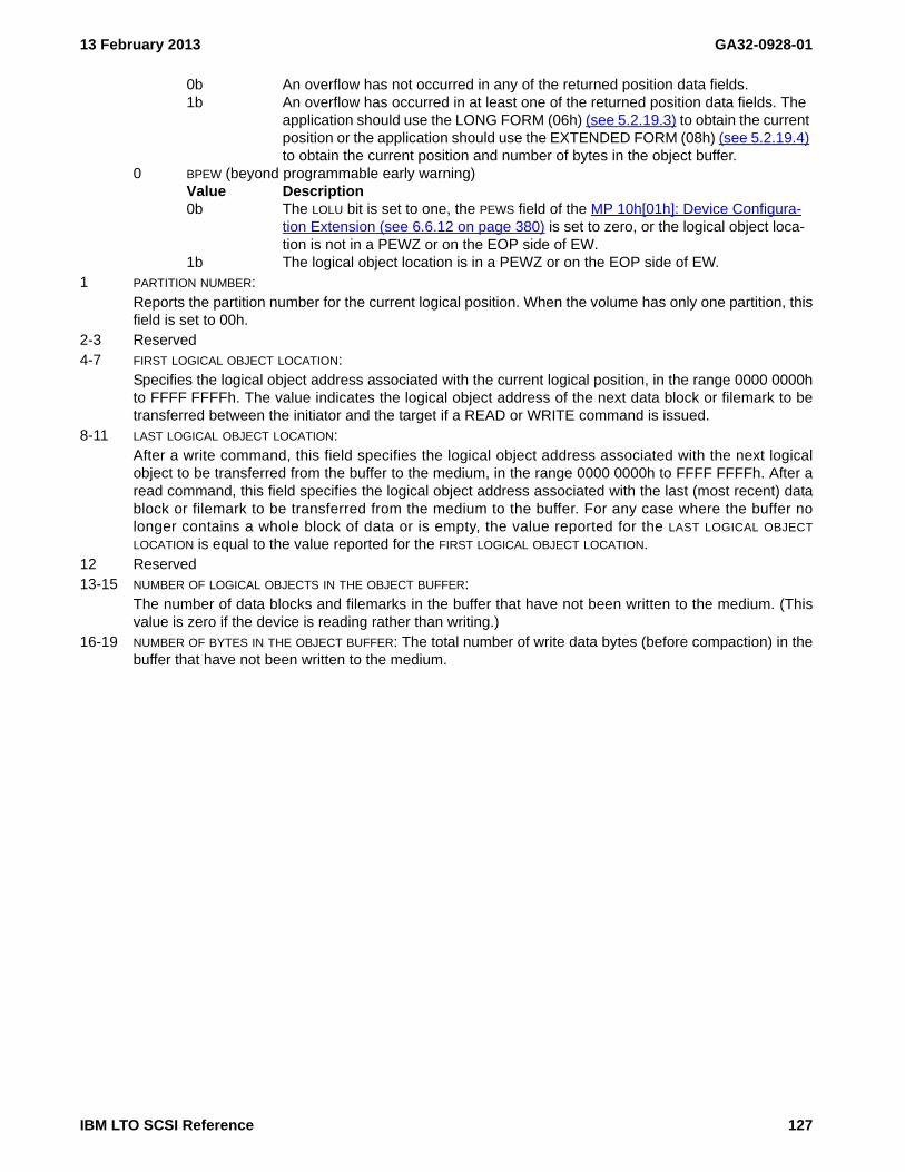
13 February 2013 GA32-0928-01
0b An overflow has not occurred in any of the returned position data fields.1b An overflow has occurred in at least one of the returned position data fields. The
application should use the LONG FORM (06h) (see 5.2.19.3) to obtain the current position or the application should use the EXTENDED FORM (08h) (see 5.2.19.4) to obtain the current position and number of bytes in the object buffer.
0 BPEW (beyond programmable early warning)Value Description0b The LOLU bit is set to one, the PEWS field of the MP 10h[01h]: Device Configura-
tion Extension (see 6.6.12 on page 380) is set to zero, or the logical object loca-tion is not in a PEWZ or on the EOP side of EW.
1b The logical object location is in a PEWZ or on the EOP side of EW.1 PARTITION NUMBER:
Reports the partition number for the current logical position. When the volume has only one partition, thisfield is set to 00h.
2-3 Reserved4-7 FIRST LOGICAL OBJECT LOCATION:
Specifies the logical object address associated with the current logical position, in the range 0000 0000hto FFFF FFFFh. The value indicates the logical object address of the next data block or filemark to betransferred between the initiator and the target if a READ or WRITE command is issued.
8-11 LAST LOGICAL OBJECT LOCATION:After a write command, this field specifies the logical object address associated with the next logicalobject to be transferred from the buffer to the medium, in the range 0000 0000h to FFFF FFFFh. After aread command, this field specifies the logical object address associated with the last (most recent) datablock or filemark to be transferred from the medium to the buffer. For any case where the buffer nolonger contains a whole block of data or is empty, the value reported for the LAST LOGICAL OBJECT
LOCATION is equal to the value reported for the FIRST LOGICAL OBJECT LOCATION.12 Reserved13-15 NUMBER OF LOGICAL OBJECTS IN THE OBJECT BUFFER:
The number of data blocks and filemarks in the buffer that have not been written to the medium. (Thisvalue is zero if the device is reading rather than writing.)
16-19 NUMBER OF BYTES IN THE OBJECT BUFFER: The total number of write data bytes (before compaction) in thebuffer that have not been written to the medium.
IBM LTO SCSI Reference 127
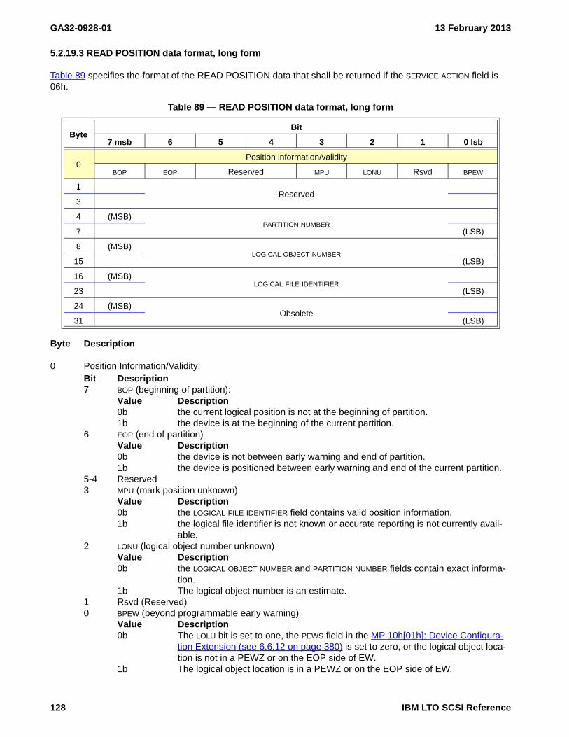
GA32-0928-01 13 February 2013
5.2.19.3 READ POSITION data format, long form
Table 89 specifies the format of the READ POSITION data that shall be returned if the SERVICE ACTION field is 06h.
Byte Description
0 Position Information/Validity:Bit Description7 BOP (beginning of partition):
Value Description0b the current logical position is not at the beginning of partition.1b the device is at the beginning of the current partition.
6 EOP (end of partition)Value Description0b the device is not between early warning and end of partition.1b the device is positioned between early warning and end of the current partition.
5-4 Reserved3 MPU (mark position unknown)
Value Description0b the LOGICAL FILE IDENTIFIER field contains valid position information.1b the logical file identifier is not known or accurate reporting is not currently avail-
able.2 LONU (logical object number unknown)
Value Description0b the LOGICAL OBJECT NUMBER and PARTITION NUMBER fields contain exact informa-
tion.1b The logical object number is an estimate.
1 Rsvd (Reserved)0 BPEW (beyond programmable early warning)
Value Description0b The LOLU bit is set to one, the PEWS field in the MP 10h[01h]: Device Configura-
tion Extension (see 6.6.12 on page 380) is set to zero, or the logical object loca-tion is not in a PEWZ or on the EOP side of EW.
1b The logical object location is in a PEWZ or on the EOP side of EW.
Table 89 — READ POSITION data format, long form
ByteBit
7 msb 6 5 4 3 2 1 0 lsb
0Position information/validity
BOP EOP Reserved MPU LONU Rsvd BPEW
1Reserved
3
4 (MSB)PARTITION NUMBER
7 (LSB)
8 (MSB)LOGICAL OBJECT NUMBER
15 (LSB)
16 (MSB)LOGICAL FILE IDENTIFIER
23 (LSB)
24 (MSB)Obsolete
31 (LSB)
128 IBM LTO SCSI Reference
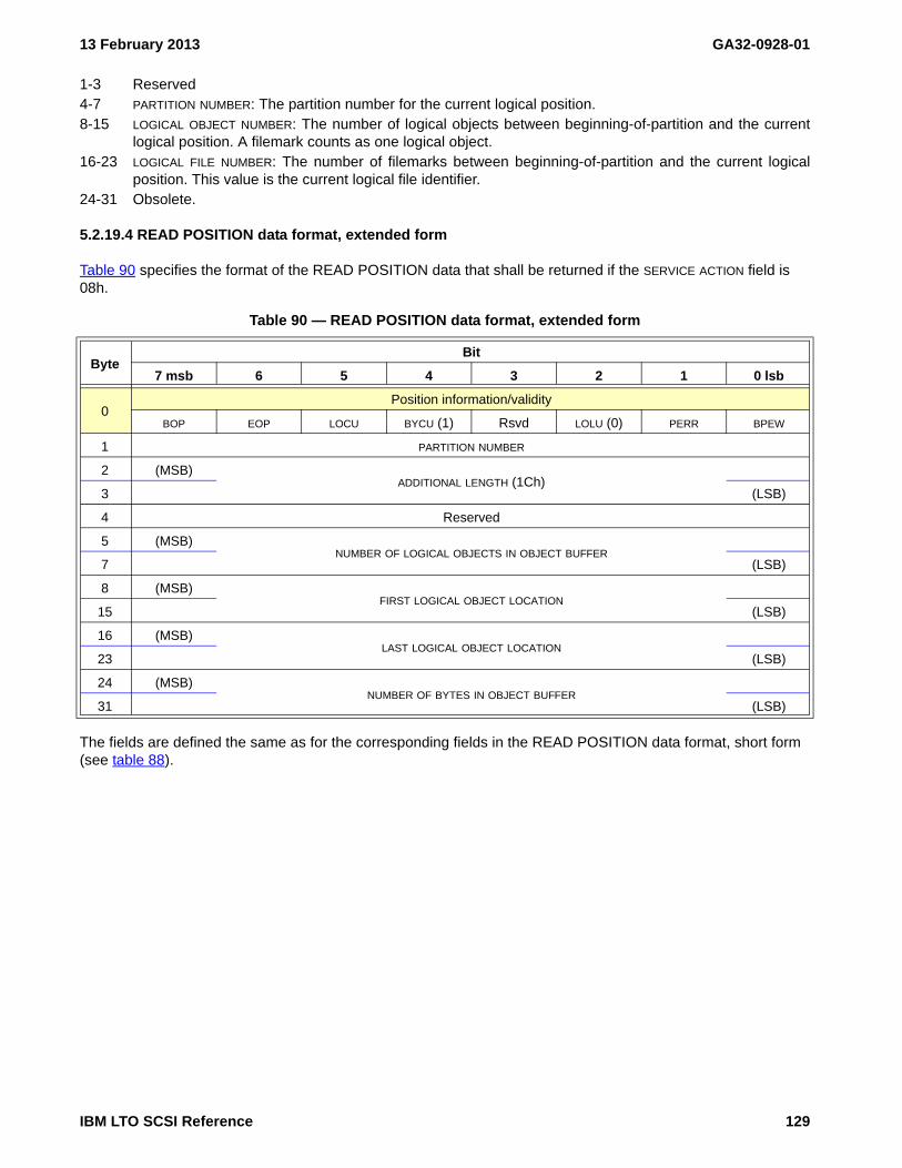
13 February 2013 GA32-0928-01
1-3 Reserved4-7 PARTITION NUMBER: The partition number for the current logical position.8-15 LOGICAL OBJECT NUMBER: The number of logical objects between beginning-of-partition and the current
logical position. A filemark counts as one logical object.16-23 LOGICAL FILE NUMBER: The number of filemarks between beginning-of-partition and the current logical
position. This value is the current logical file identifier.24-31 Obsolete.
5.2.19.4 READ POSITION data format, extended form
Table 90 specifies the format of the READ POSITION data that shall be returned if the SERVICE ACTION field is 08h.
The fields are defined the same as for the corresponding fields in the READ POSITION data format, short form (see table 88).
Table 90 — READ POSITION data format, extended form
ByteBit
7 msb 6 5 4 3 2 1 0 lsb
0Position information/validity
BOP EOP LOCU BYCU (1) Rsvd LOLU (0) PERR BPEW
1 PARTITION NUMBER
2 (MSB)ADDITIONAL LENGTH (1Ch)
3 (LSB)
4 Reserved
5 (MSB)NUMBER OF LOGICAL OBJECTS IN OBJECT BUFFER
7 (LSB)
8 (MSB)FIRST LOGICAL OBJECT LOCATION
15 (LSB)
16 (MSB)LAST LOGICAL OBJECT LOCATION
23 (LSB)
24 (MSB)NUMBER OF BYTES IN OBJECT BUFFER
31 (LSB)
IBM LTO SCSI Reference 129

GA32-0928-01 13 February 2013
The ADDITIONAL LENGTH field shall contain 1Ch. If the information transferred to the Data-In Buffer is truncated because of an insufficient ALLOCATION LENGTH value, the ADDITIONAL LENGTH field shall not be altered to reflect the truncation.
Byte Description
0 Position Information/Validity:Bit Description7 BOP (beginning of partition):
Value Description0b the current logical position is not at the beginning of partition.1b the device is at the beginning of the current partition.
6 EOP (end of partition)Value Description0b the device is not between early warning and end of partition.1b the device is positioned between early warning and end of the current partition.
5 LOCU (logical object count unknown)Value Description0b block count is exact1b block count is an estimate
4 BYCU (byte count unknown)Value Description0b byte count is exact1b byte count is an estimate
3 Reserved2 LOLU (logical object location unknown)
Value Description0b block position is exact1b block position is an estimate
1 PERR (position error): Value Description0b An overflow has not occurred in any of the returned position data fields.1b An overflow has occurred in at least one of the returned position data fields.
0 BPEW (beyond programmable early warning)Value Description0b The LOLU bit is set to one, the PEWS field in MP 10h[01h]: Device Configuration
Extension (see 6.6.12 on page 380) is set to zero, or the logical object location is not in a PEWZ or on the EOP side of EW.
1b The logical object location is in a PEWZ or on the EOP side of EW.1 PARTITION NUMBER:
Reports the partition number for the current logical position. When the volume has only one partition, thisfield is set to 00h.
2-3 ADDITIONAL LENGTH: 1Ch4 Reserved5-7 NUMBER OF LOGICAL OBJECTS IN THE OBJECT BUFFER:
The number of data blocks and filemarks in the buffer that have not been written to the medium. (Thisvalue is zero if the device is reading rather than writing.)
8-15 FIRST LOGICAL OBJECT LOCATION:Specifies the logical object address associated with the current logical position, in the range 0000 0000hto FFFF FFFFh. The value indicates the logical object address of the next data block or filemark to betransferred between the initiator and the target if a READ or WRITE command is issued.
16-23 LAST LOGICAL OBJECT LOCATION:After a write command, this field specifies the logical object address associated with the next logicalobject to be transferred from the buffer to the medium, in the range 0000 0000h to FFFF FFFFh. After aread command, this field specifies the logical object address associated with the last (most recent) data
130 IBM LTO SCSI Reference

13 February 2013 GA32-0928-01
block or filemark to be transferred from the medium to the buffer. For any case where the buffer nolonger contains a whole block of data or is empty, the value reported for the LAST LOGICAL OBJECT
LOCATION is equal to the value reported for the FIRST LOGICAL OBJECT LOCATION.24-31 NUMBER OF BYTES IN THE OBJECT BUFFER: The total number of write data bytes (before compaction) in the
buffer that have not been written to the medium.
IBM LTO SCSI Reference 131

GA32-0928-01 13 February 2013
5.2.20 RECEIVE DIAGNOSTIC RESULTS - 1Ch
The Receive Diagnostic Results command is defined in SPC (see the latest version at http://www.t10.org/drafts.htm#SCSI3_CMNDSETS). This clause decribes the specific implementation.
After a Send Diagnostic command completes, use the Receive Diagnostic Results command to receive the results.
As allowed by the SCSI standards, devices may implement Send Diagnostic and handle status and return information for diagnostics in somewhat different manners. To work correctly with all common variations, the following sequence should be used by the host.
The SEND DIAGNOSTIC command is issued. If a CHECK CONDITION status occurs, and a non-deferred permanent error results, then the test failed (or was not started if sense key=ILLEGAL REQUEST). If GOOD status is returned, then a RECEIVE DIAGNOSTICS RESULTS command should be issued, and:
a) the “blocked” and “error” bit should be checked (byte 8, bits 2 and 0 respectively), and if either is set, thediagnostic was either not run or failed; and
d) if byte 8 bit 1 is set, the SIM/MIM data in the results is valid and contains additional information relating to the failure
NOTE 20 - This process is required by this device to determine diagnostics results for those diagnostics which indicate diagnostics results data is returned. GOOD status returned from the Send Diagnostic only indicates that the diagnostic was accepted but does not indicate the ultimate result of its execution.
NOTE 21 - For diagnostics that produce diagnostic results, the device should be reserved using the Reserve or Persistent Reserve Out command to protect the results from actions of other initiators.
Table 91 shows the command format.
The following parameters apply:
• ALLOCATION LENGTH: The maximum number of bytes to be returned in the page of data following the com-mand (if any).
Diagnostic Parameters (Diag) (see 6.2 on page 195) has a listing of all diagnostic parameters.
Table 91 — RECEIVE DIAGNOSTIC RESULTS CDB
ByteBit
7 msb 6 5 4 3 2 1 0 lsb
0 OPERATION CODE (1Ch)
1 Obsolete Reserved
2 Reserved
3 MSBALLOCATION LENGTH
4 LSB
5 Control Byte (see 5.1.2.3)
132 IBM LTO SCSI Reference
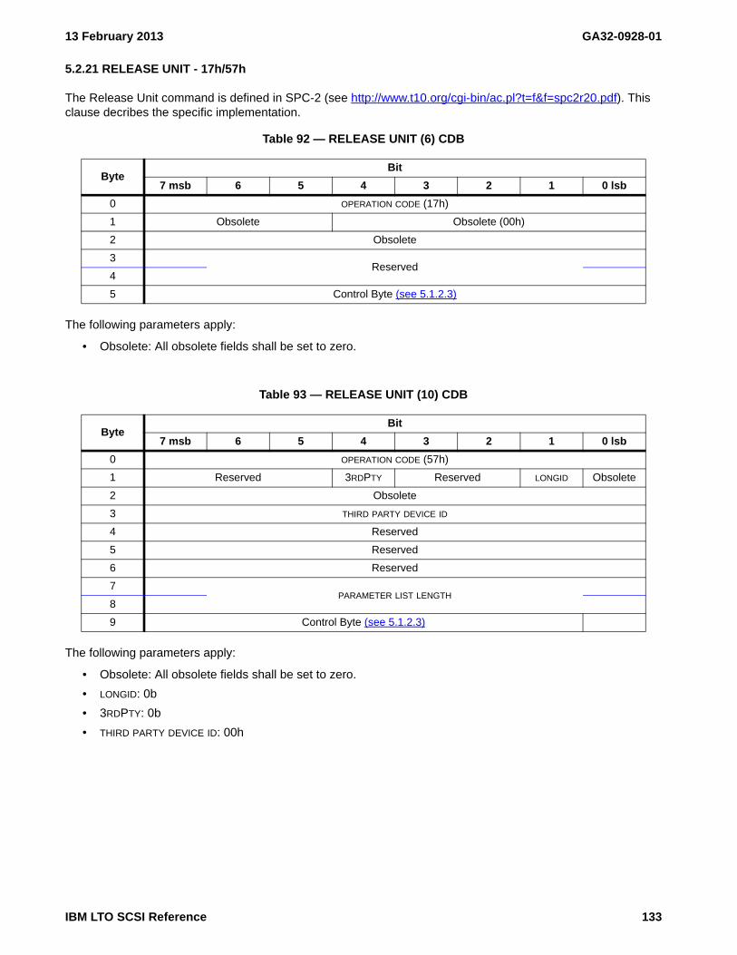
13 February 2013 GA32-0928-01
5.2.21 RELEASE UNIT - 17h/57h
The Release Unit command is defined in SPC-2 (see http://www.t10.org/cgi-bin/ac.pl?t=f&f=spc2r20.pdf). This clause decribes the specific implementation.
The following parameters apply:
• Obsolete: All obsolete fields shall be set to zero.
The following parameters apply:
• Obsolete: All obsolete fields shall be set to zero.
• LONGID: 0b
• 3RDPTY: 0b
• THIRD PARTY DEVICE ID: 00h
Table 92 — RELEASE UNIT (6) CDB
ByteBit
7 msb 6 5 4 3 2 1 0 lsb
0 OPERATION CODE (17h)
1 Obsolete Obsolete (00h)
2 Obsolete
3Reserved
4
5 Control Byte (see 5.1.2.3)
Table 93 — RELEASE UNIT (10) CDB
ByteBit
7 msb 6 5 4 3 2 1 0 lsb
0 OPERATION CODE (57h)
1 Reserved 3RDPTY Reserved LONGID Obsolete
2 Obsolete
3 THIRD PARTY DEVICE ID
4 Reserved
5 Reserved
6 Reserved
7PARAMETER LIST LENGTH
8
9 Control Byte (see 5.1.2.3)
IBM LTO SCSI Reference 133

GA32-0928-01 13 February 2013
5.2.22 REPORT DENSITY SUPPORT - 44h
The Report Density Support command is defined in SSC (see the latest version at http://www.t10.org/drafts.htm#SCSI3_CMNDSETS). This clause decribes the specific implementation.
The following parameters apply:
• MEDIA:Value Description0b report all supported densities for all supported medium types1b report all supported densities for the current medium in the drive. If the device is not ready,
the drive will return 2/0400h (NOT READY, NOT READY CAUSE NOT REPORTABLE).
• ALLOCATION LENGTH: The maximum number of bytes to be transferred.
5.2.22.1 Report Density Support data format
5.2.22.1.1 Density descriptor overview
Density descriptors contain information that may be returned by the drive. While the information is reported in a manner useful to applications, SSC-4 specifies fields that have been found to not be useful by applications in selecting which density to use. Instead applications have been found to ignore the BITS PER MM field and the TRACKS field. This device does not change the values returned in these fields by the format type – media type combinations and instead returns the largest value for the set of supported format type media type combinations. The CAPACITY field is used by applications and does report values based on the format type – media type combinations. The DENSITY CODE fields, the ASSIGNING ORGANIZATION field, the DENSITY NAME field, and the DESCRIPTION field are constant per density and are correctly reported.
This device may return different combinations of the descriptors in the REPORT DENSITY SUPPORT data depending on drive generation, medium loaded, setting of the MEDIA bit, and settings of various mode parameters related to densities.
Table 94 — REPORT DENSITY SUPPORT CDB
ByteBit
7 msb 6 5 4 3 2 1 0 lsb
0 OPERATION CODE (44h)
1 Reserved MEDIA
2Reserved
6
7 MSBALLOCATION LENGTH
8 LSB
9 Control Byte (see 5.1.2.3)
134 IBM LTO SCSI Reference

13 February 2013 GA32-0928-01
The Report Density Support data format is shown in table 95.
The Density support data block descriptor format is shown in table 96.
Table 95 — REPORT DENSITY SUPPORT data format
ByteBit
7 6 5 4 3 2 1 0
0 (MSB)AVAILABLE DENSITY SUPPORT LENGTH
1 (LSB)
2 Reserved
3 Reserved
Density support data block descriptors
4Density support data block descriptor [first]
…
Density support data block descriptor [last]
n
Table 96 — Density support data block descriptor format
ByteBit
7 6 5 4 3 2 1 0
0 PRIMARY DENSITY CODE
1 SECONDARY DENSITY CODE
2 WRTOK DUP DEFLT Reserved DLV
3 (MSB)DESCRIPTOR LENGTH
4 (LSB)
5 (MSB)BITS PER MM
7 (LSB)
8 (MSB)MEDIA WIDTH
9 (LSB)
10 (MSB)TRACKS
11 (LSB)
12 (MSB)CAPACITY
15 (LSB)
16ASSIGNING ORGANIZATION
23
24DENSITY NAME
31
32DESCRIPTION
51
IBM LTO SCSI Reference 135
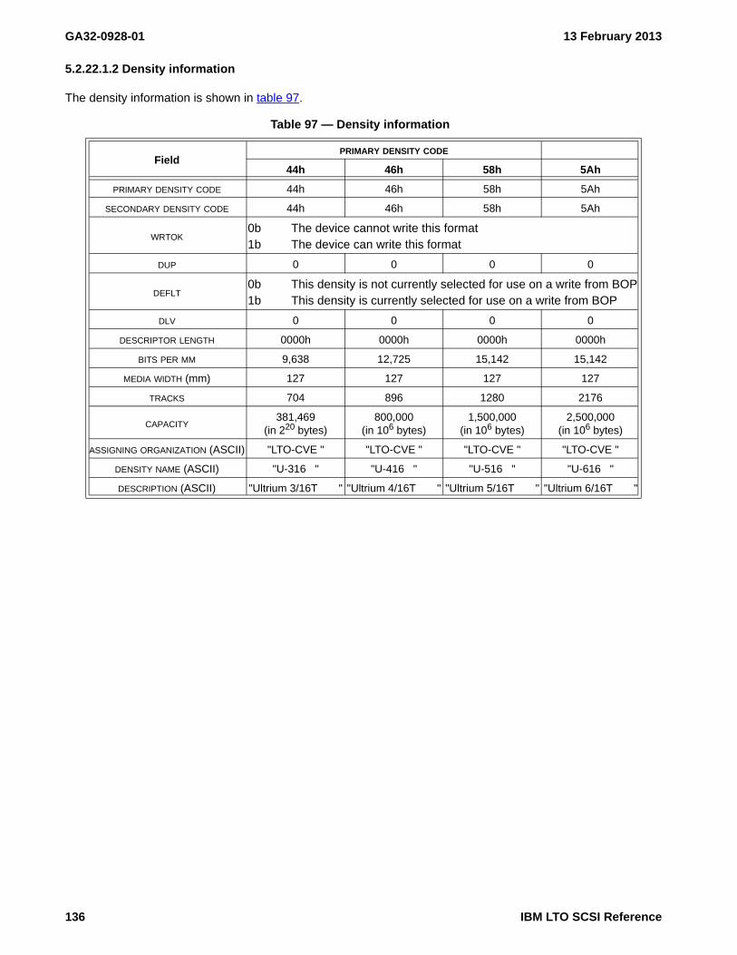
GA32-0928-01 13 February 2013
5.2.22.1.2 Density information
The density information is shown in table 97.
Table 97 — Density information
FieldPRIMARY DENSITY CODE
44h 46h 58h 5Ah
PRIMARY DENSITY CODE 44h 46h 58h 5Ah
SECONDARY DENSITY CODE 44h 46h 58h 5Ah
WRTOK0b The device cannot write this format1b The device can write this format
DUP 0 0 0 0
DEFLT0b This density is not currently selected for use on a write from BOP1b This density is currently selected for use on a write from BOP
DLV 0 0 0 0
DESCRIPTOR LENGTH 0000h 0000h 0000h 0000h
BITS PER MM 9,638 12,725 15,142 15,142
MEDIA WIDTH (mm) 127 127 127 127
TRACKS 704 896 1280 2176
CAPACITY381,469
(in 220 bytes)800,000
(in 106 bytes)1,500,000
(in 106 bytes)2,500,000
(in 106 bytes)
ASSIGNING ORGANIZATION (ASCII) "LTO-CVE " "LTO-CVE " "LTO-CVE " "LTO-CVE "
DENSITY NAME (ASCII) "U-316 " "U-416 " "U-516 " "U-616 "
DESCRIPTION (ASCII) "Ultrium 3/16T " "Ultrium 4/16T " "Ultrium 5/16T " "Ultrium 6/16T "
136 IBM LTO SCSI Reference

13 February 2013 GA32-0928-01
5.2.23 REPORT LUNS - A0h
The Report LUNs command is defined in SPC (see the latest version at http://www.t10.org/drafts.htm#SCSI3_CMNDSETS). This clause decribes the specific implementation.
The following parameters apply:
• ALLOCATION LENGTH: Tthe maximum number of bytes to be transferred.
5.2.23.1 Report LUNs data format
Table 99 shows the data that is returned:
Byte Description
0-3 LUN LIST LENGTH (n-7): This field will be set to 8 times the number of LUNs configured in the device.There will always be a LUN 0. There may be a library LUN (i.e., LUN 1) and/or there may be an ADCLUN (i.e., LUN 2).
4-7 Reserved8-15 FIRST LUN: 0000 0000 0000 0000h (i.e., LUN 0)
Table 98 — REPORT LUNS CDB
ByteBit
7 msb 6 5 4 3 2 1 0 lsb
0 OPERATION CODE (A0h)
1Reserved
5
6 MSBALLOCATION LENGTH
9 LSB
10 Reserved
11 Control Byte (see 5.1.2.3)
Table 99 — Logical Unit Numbers Data
ByteBit
7 6 5 4 3 2 1 0
0 (MSB)LUN LIST LENGTH
3 (LSB)
4Reserved
7
LUN list
8 (MSB)FIRST LUN
15 (LSB)
…
n-7 (MSB)LAST LUN
n (LSB)
IBM LTO SCSI Reference 137

GA32-0928-01 13 February 2013
16-23 Second LUN, if anyLUN DescriptionLUN 1 0001 0000 0000 0000h (returned only if LUN 1 exists)LUN 2 0002 0000 0000 0000h (returned only if LUN 1 does not exist and the device is configured
for ADI and the ENABLE bit of LOGICAL UNIT INDEX 02h in Mode Page 0Eh subpage 03h of the ADC LUN (i.e., LUN 2) is set to one.
24-31 LAST LUN, if anyLUN DescriptionLUN 2 0002 0000 0000 0000h (returned only if LUN 1 exists and configured for ADI and the
ENABLE bit of LOGICAL UNIT INDEX 02h in Mode Page 0Eh subpage 03h of the ADC LUN (i.e., LUN 2) is set to one.
NOTE 22 - If this command is received over the ADT port , then a LUN descriptor is returned with a value of 0002000000000000h, even if the ENABLE bit of LOGICAL UNIT INDEX 02h in Mode Page 0Eh subpage 03h is set to zero.
138 IBM LTO SCSI Reference

13 February 2013 GA32-0928-01
5.2.24 REPORT SUPPORTED OPERATION CODES - A3h[0Ch]
The Report LUNs command is defined in SPC (see the latest version at http://www.t10.org/drafts.htm#SCSI3_CMNDSETS). This clause decribes the specific implementation. Ultrium 5 and later devices support the REPORT SUPPORTED OPERATION CODES command. The REPORT SUPPORTED OPERATION CODES command (see table 100) requests information on commands the addressed logical unit supports. An application client may request a list of all operation codes and service actions supported by the logical unit or the command support data for a specific command.
The REPORT SUPPORTED OPERATION CODES command is a service action of the MAINTENANCE IN command.
A return command timeouts descriptor (RCTD) bit set to one specifies that the command timeouts descriptor (see 5.2.24.3) shall be included in each command descriptor (see 5.2.24.1) that is returned or in the one_command parameter data (see 5.2.24.2) that is returned. A RCTD bit set to zero specifies that the command timeouts descriptor shall not be included in any parameter data returned.
Table 100 — REPORT SUPPORTED OPERATION CODES CDB
ByteBit
7 6 5 4 3 2 1 0
0 OPERATION CODE (A3h)
1 Reserved SERVICE ACTION (0Ch)
2 RCTD Reserved REPORTING OPTIONS
3 REQUESTED OPERATION CODE
4 (MSB)REQUESTED SERVICE ACTION
5 (LSB)
6 (MSB)ALLOCATION LENGTH
9 (LSB)
10 Reserved
11 Control Byte (see 5.1.2.3)
IBM LTO SCSI Reference 139

GA32-0928-01 13 February 2013
The REPORTING OPTIONS field (see table 101) specifies the information to be returned in the parameter data.
The REQUESTED OPERATION CODE field specifies the operation code of the command to be returned in the one_command parameter data format (see 5.2.24.2).
The REQUESTED SERVICE ACTION field specifies the service action of the command to be returned in the one_command parameter data format.
The ALLOCATION LENGTH field specifies the maximum number of bytes or blocks that an application client has allocated in the Data-In Buffer.
5.2.24.1 All_commands parameter data format
The REPORT SUPPORTED OPERATION CODES all_commands parameter data format (see table 102) begins with a four-byte header that contains the length in bytes of the parameter data followed by a list of supported commands. Each command descriptor contains information about a single supported command CDB (i.e., one operation code and service action combination, or one non-service-action operation code). The list of command descriptors shall contain all commands supported by the logical unit.
Table 101 — REPORT SUPPORTED OPERATION CODES REPORTING OPTIONS field
Code DescriptionParameter Data
Reference
000b
A list of all operation codes and service actions supported by the logical unit shall be returned in the all_commands parameter data format. The REQUESTED OPERATION CODE CDB field and REQUESTED SERVICE ACTION CDB field shall be ignored.
5.2.24.1
001b
The command support data for the operation code specified in the REQUESTED OPERATION CODE field shall be returned in the one_command parameter data format. The REQUESTED SERVICE ACTION CDB field shall be ignored. If the REQUESTED OPERATION CODE field specifies an operation code that has service actions, then the command shall be terminated with CHECK CONDITION status, with the sense key set to ILLEGAL REQUEST, and the additional sense code set to INVALID FIELD IN CDB.
5.2.24.2
010b
The command support data for the operation code and service action specified in the REQUESTED OPERATION CODE CDB field and REQUESTED SERVICE ACTION CDB field shall be returned in the one_command parameter data format. If the REQUESTED OPERATION CODE CDB field specifies an operation code that does not have service actions, then the command shall be terminated with CHECK CONDITION status, with the sense key set to ILLEGAL REQUEST, and the additional sense code set to INVALID FIELD IN CDB.
5.2.24.2
011b to 111b Reserved
Table 102 — All_commands parameter data
ByteBit
7 6 5 4 3 2 1 0
0 (MSB)COMMAND DATA LENGTH (n-3)
3 (LSB)
Command descriptors
4Command descriptor 0 (see table 103)
…
Command descriptor x (see table 103)n
140 IBM LTO SCSI Reference

13 February 2013 GA32-0928-01
The COMMAND DATA LENGTH field indicates the length in bytes of the command descriptor list.
Each command descriptor (see table 103) contains information about a single supported command CDB.
The OPERATION CODE field contains the operation code of a command supported by the logical unit.
The SERVICE ACTION field contains a supported service action of the supported operation code indicated by the OPERATION CODE field. If the operation code indicated in the OPERATION CODE field does not have a service actions, the SERVICE ACTION field shall be set to 00h.
A command timeouts descriptor present (CTDP) bit set to one indicates that the command timeouts descriptor (see 5.2.24.3) is included in this command descriptor. A CTDP bit set to zero indicates that the command timeouts descriptor is not included in this command descriptor.
A service action valid (SERVACTV) bit set to zero indicates the operation code indicated by the OPERATION CODE field does not have service actions and the SERVICE ACTION field contents are reserved. A SERVACTV bit set to one indicates the operation code indicated by the OPERATION CODE field has service actions and the contents of the SERVICE ACTION field are valid.
The CDB LENGTH field contains the length of the command CDB in bytes for the operation code indicated in the OPERATION CODE field, and if the SERVACTV bit is set to the service action indicated by the SERVICE ACTION field.
If the RCTD bit is set to one in the REPORT SUPPORTED OPERATION CODES CDB (see 5.2.24), the command timeouts descriptor (see table 106 in 5.2.24.3) shall be included. If the RCTD bit is set to zero, the command timeouts descriptor shall not be included.
Table 103 — Command descriptor format
ByteBit
7 6 5 4 3 2 1 0
0 OPERATION CODE
1 Reserved
2 (MSB)SERVICE ACTION
3 (LSB)
4 Reserved
5 Reserved CTDP SERVACTV
6 (MSB)CDB LENGTH
7 (LSB)
8Command timeouts descriptor, if any (see 5.2.24.3)
19
IBM LTO SCSI Reference 141

GA32-0928-01 13 February 2013
5.2.24.2 One_command parameter data format
The REPORT SUPPORTED OPERATION CODES one_command parameter data format (see table 104) contains information about the CDB and a usage map for bits in the CDB for the command specified by the REPORTING OPTIONS, REQUESTED OPERATION CODE, and REQUESTED SERVICE ACTION fields in the REPORT SUPPORTED OPERATION CODES CDB.
A command timeouts descriptor present (CTDP) bit set to one indicates that the command timeouts descriptor (see 5.2.24.3) is included in the parameter data. A CTDP bit set to zero indicates that the command timeouts descriptor is not included in the parameter data.
The SUPPORT field is defined in table 105.
The CDB SIZE field contains the size of the CDB USAGE DATA field in the parameter data, and the number of bytes in the CDB for command being queried (i.e., the command specified by the REPORTING OPTIONS, REQUESTED OPERATION CODE, and REQUESTED SERVICE ACTION fields in the REPORT SUPPORTED OPERATION CODES CDB).
The CDB USAGE DATA field contains information about the CDB for the command being queried. The first byte of the CDB USAGE DATA field shall contain the operation code for the command being queried. If the command being queried contains a service action, then that service action code shall be placed in the CDB USAGE DATA field in the same location as the SERVICE ACTION field of the command CDB. All other bytes of the CDB USAGE DATA field shall contain a usage map for bits in the CDB for the command being queried.
The bits in the usage map shall have a one-for-one correspondence to the CDB for the command being queried. If the device server evaluates a bit in the CDB for the command being queried, the usage map shall contain a one in the corresponding bit position. If any bit representing part of a field is returned as one, all bits for the field shall be returned as one. If the device server ignores or treats as reserved a bit in the CDB for the command
Table 104 — One_command parameter data
ByteBit
7 6 5 4 3 2 1 0
0 Reserved
1 CTDP Reserved SUPPORT
2 (MSB)CDB SIZE (n-3)
3 (LSB)
4CDB USAGE DATA
n
n+1Command timeouts descriptor, if any (see 5.2.24.3)
n+12
Table 105 — SUPPORT values
Support Description
000bData about the requested SCSI command is not currently available. All data after byte 1 is not valid. A subsequent request for command support data may be successful.
001b The device server does not support the requested command. All data after byte 1 is undefined.
010b Reserved
011bThe device server supports the requested command in conformance with a SCSI standard. The parameter data format conforms to the definition in table 104.
100b Reserved
101bThe device server supports the requested command in a vendor specific manner. The parameter data format conforms to the definition in table 104.
110b to 111b Reserved
142 IBM LTO SCSI Reference

13 February 2013 GA32-0928-01
being queried, the usage map shall contain a zero in the corresponding bit position. The usage map bits for a given CDB field all shall have the same value.
For example, the CDB usage bit map for the REPORT SUPPORTED OPERATION CODES command is: A3h, 0Ch, 87h, FFh, FFh, FFh, FFh, FFh, FFh, FFh, 00h, 07h. This example assumes that the logical unit only supports the low-order three bits of the CDB CONTROL byte. The first byte contains the operation code, and the second byte contains three reserved bits and the service action. The remaining bytes contain the usage map.
If the RCTD bit is set to one in the REPORT SUPPORTED OPERATION CODES CDB (see 5.2.24), the command timeouts descriptor (see table 106 in 5.2.24.3) shall be included. If the RCTD bit is set to zero, the command timeouts descriptor shall not be included.
5.2.24.3 Command timeouts descriptor
5.2.24.3.1 Overview
The command timeouts descriptor (see table 106) returns timeout information for commands supported by the logical unit based on the time from the start of processing for the command to its reported completion.
Values returned in the command timeouts descriptor do not include times that are outside the control of the device server (e.g., prior commands with the IMMED bit set to one in the CDB, concurrent commands from the same or different I_T nexuses, manual unloads, power-on self tests, prior aborted commands, commands that force cache synchronization, delays in the service delivery subsystem).
For commands that cause a change in power condition, values returned in the command timeouts descriptor do not include the power condition transition time (e.g., the time to thread the media).
Values returned in the command timeouts descriptor should not be used to compare products.
The DESCRIPTOR LENGTH field indicates the number of bytes that follow in the command timeouts descriptor.
The COMMAND SPECIFIC field contains timeout information that is specific to the commands listed in table 107.
A non-zero value in the NOMINAL COMMAND PROCESSING TIMEOUT field indicates the minimum amount of time in seconds the application client should wait prior to querying for the progress of the command identified by the parameter data that contains this command timeouts descriptor. A value of zero in the NOMINAL COMMAND PROCESSING TIMEOUT field indicates that no timeout is indicated.
Table 106 — Command timeouts descriptor format
ByteBit
7 6 5 4 3 2 1 0
0 (MSB)DESCRIPTOR LENGTH (0Ah)
1 (LSB)
2 Reserved
3 COMMAND SPECIFIC
4 (MSB)NOMINAL COMMAND PROCESSING TIMEOUT
7 (LSB)
8 (MSB)RECOMMENDED COMMAND TIMEOUT
11 (LSB)
Table 107 — Command timeouts descriptor COMMAND SPECIFIC field usage
Command Reference
WRITE BUFFER 5.2.24.3.2
IBM LTO SCSI Reference 143

GA32-0928-01 13 February 2013
NOTE 23 - The value contained in the NOMINAL COMMAND PROCESSING TIMEOUT field may include time required for typical device error recovery procedures expected to occur on a regular basis.
A non-zero value in the RECOMMENDED COMMAND TIMEOUT field specifies the recommended time in seconds the application client should wait prior to timing out the command identified by the parameter data that contains this command timeouts descriptor. A value of zero in the RECOMMENDED COMMAND TIMEOUT field indicates that no time is indicated.
The device server should set the recommended command timeout to a value greater than or equal to the nominal command processing timeout.
Application clients should use the Report Supported Operation Codes command to discover command timeout values. Table 108 lists the command timeout values at the time this document was published for the commands supported at the time the document was published. These values may have changed since publication.
Due to the sequential nature of tape devices, many host commands are serialized, and command timeouts consequently have an additive effect. Using reservations prevents this from causing application disruptions in a multi-initiator or SAN environment. Similar additive timeout effects may occur if the host is using command queuing (simple queuing).
NOTE 24 - The time-outs in the following table are based on the time from the start of processing of the command, to its reported completion. Since applications are generally concerned with the time from the command being issued, to its reported completion, it should be noted that this overall time may be affected by currently processing operations. Some of these conditions include:
a) A prior command was issued with the Immediate bit set in the CDB b) Multiple concurrent commands with Simple queuing are processed c) Multi-initiator configurations without reservations d) Non-host operations, such as manual unloads, power-on self tests, etc. e) Commands issued shortly after certain aborted commandsf) Commands which force flushes when unwritten write data is in the buffer
Table 108 — Command timeout values at time document was published (part 1 of 4)
OpCodes
ServiceAction
Command
Ultrium 5 Ultrium 6
Full-Height Half-Height Full-Height Half-Height
Nom Rec Nom Rec Nom Rec Nom Rec
00h 0000h TEST UNIT READY 60 60 60 60 60 60 60 60
01h 0000h REWIND 300 600 300 780 300 600 300 780
03h 0000h REQUEST SENSE 60 60 60 60 60 60 60 60
04h 0000h FORMAT MEDIUM 300 1 560 300 1 980 480 3 000 480 3 840
05h 0000h READ BLOCK LIMITS 60 60 60 60 60 60 60 60
08h 0000h READ 300 1 500 300 1 920 300 1 500 300 1 920
0Ah 0000h WRITE 300 1 500 300 1 920 300 1 500 300 1 920
0Bh 0000h SET CAPACITY 300 780 300 960 300 780 300 960
10h 0000h WRITE FILEMARK 300 1 620 300 1 740 300 1 620 300 1 740
11h 0000h SPACE (6) 300 2 040 360 2 700 300 2 040 360 2 700
(slow—e.g., lost directory) a 13 800 16 920 13 800 19 980 20 400 25 200 20 400 30 000
12h 0000h INQUIRY 60 60 60 60 60 60 60 60
13h 0000h VERIFY(VTE=0b and VBF=0b) 300 1 500 300 1 920 300 1 500 300 1 920
(VTE=1b or VBF=1b) a 13 800 16 920 13 800 19 980 20 400 25 200 20 400 30 000a This row is NOT returned in a command timeouts descriptor.
144 IBM LTO SCSI Reference

13 February 2013 GA32-0928-01
15h 0000h MODE SELECT (6) 60 60 60 60 60 60 60 60
16h 0000h RESERVE UNIT (6) 60 60 60 60 60 60 60 60
17h 0000h RELEASE UNIT (6) 60 60 60 60 60 60 60 60
19h 0000h ERASE 13 800 16 380 13 800 19 200 20 400 24 600 20 400 29 400
1Ah 0000h MODE SENSE (6) 60 60 60 60 60 60 60 60
1Bh 0000h LOAD/UNLOAD 300 780 360 1 020 300 780 360 1 020
1Ch 0000h RECEIVE DIAGNOSTIC RESULTS 60 60 60 60 60 60 60 60
1Dh 0000h SEND DIAGNOSTIC 900 2 100 960 3 120 900 2 100 960 3 120
1Eh 0000h PREVENT/ALLOW MEDIUM REMOVAL 60 60 60 60 60 60 60 60
2Bh 0000h LOCATE (10) 300 2 040 360 2 700 300 2 040 360 2 700
(slow—e.g., lost directory) a 13 800 16 920 13 800 19 980 20 400 25 200 20 400 30 000
34h 0000hREAD POSITION —[SHORT FORM -- BLOCK ID]
60 60 60 60 60 60 60 60
34h 0006hREAD POSITION —[LONG FORM]
60 60 60 60 60 60 60 60
34h 0008hREAD POSITION —[EXTENDED FORM]
60 60 60 60 60 60 60 60
3Bh 0000h WRITE BUFFER 300 540 300 720 300 540 300 720
3Ch 0000h READ BUFFER 300 480 300 660 300 480 300 660
44h 0000h REPORT DENSITY SUPPORT 60 60 60 60 60 60 60 60
4Ch 0000h LOG SELECT 60 60 60 60 60 60 60 60
4Dh 0000h LOG SENSE 60 60 60 60 60 60 60 60
55h 0000h MODE SELECT (10) 60 60 60 60 60 60 60 60
56h 0000h RESERVE UNIT (10) 60 60 60 60 60 60 60 60
57h 0000h RELEASE UNIT (10) 60 60 60 60 60 60 60 60
5Ah 0000h MODE SENSE (10) 60 60 60 60 60 60 60 60
5Eh 0000hPERSISTENT RESERVE IN —[READ KEYS]
60 60 60 60 60 60 60 60
5Eh 0001hPERSISTENT RESERVE IN —[READ RESERVATION]
60 60 60 60 60 60 60 60
5Eh 0002hPERSISTENT RESERVE IN —[REPORT CAPABILITIES]
60 60 60 60 60 60 60 60
5Eh 0003hPERSISTENT RESERVE IN —[READ FULL STATUS]
60 60 60 60 60 60 60 60
5Fh 0000hPERSISTENT RESERVE OUT —[REGISTER]
60 60 60 60 60 60 60 60
5Fh 0001hPERSISTENT RESERVE OUT —[RESERVE]
60 60 60 60 60 60 60 60
5Fh 0002hPERSISTENT RESERVE OUT —[RELEASE]
60 60 60 60 60 60 60 60
Table 108 — Command timeout values at time document was published (part 2 of 4)
OpCodes
ServiceAction
Command
Ultrium 5 Ultrium 6
Full-Height Half-Height Full-Height Half-Height
Nom Rec Nom Rec Nom Rec Nom Rec
a This row is NOT returned in a command timeouts descriptor.
IBM LTO SCSI Reference 145
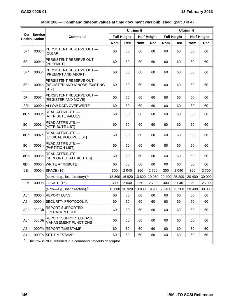
GA32-0928-01 13 February 2013
5Fh 0003hPERSISTENT RESERVE OUT —[CLEAR]
60 60 60 60 60 60 60 60
5Fh 0004hPERSISTENT RESERVE OUT —[PREEMPT]
60 60 60 60 60 60 60 60
5Fh 0005hPERSISTENT RESERVE OUT —[PREEMPT AND ABORT]
60 60 60 60 60 60 60 60
5Fh 0006hPERSISTENT RESERVE OUT —[REGISTER AND IGNORE EXISTING KEY]
60 60 60 60 60 60 60 60
5Fh 0007hPERSISTENT RESERVE OUT —[REGISTER AND MOVE]
60 60 60 60 60 60 60 60
82h 0000h ALLOW DATA OVERWRITE 60 60 60 60 60 60 60 60
8Ch 0000hREAD ATTRIBUTE —[ATTRIBUTE VALUES]
60 60 60 60 60 60 60 60
8Ch 0001hREAD ATTRIBUTE —[ATTRIBUTE LIST]
60 60 60 60 60 60 60 60
8Ch 0002hREAD ATTRIBUTE —[LOGICAL VOLUME LIST]
60 60 60 60 60 60 60 60
8Ch 0003hREAD ATTRIBUTE —[PARTITION LIST]
60 60 60 60 60 60 60 60
8Ch 0005hREAD ATTRIBUTE —[SUPPORTED ATTRIBUTES]
60 60 60 60 60 60 60 60
8Dh 0000h WRITE ATTRIBUTE 60 60 60 60 60 60 60 60
91h 0000h SPACE (16) 300 2 040 360 2 700 300 2 040 360 2 700
(slow—e.g., lost directory) a 13 800 16 920 13 800 19 980 20 400 25 200 20 400 30 000
92h 0000h LOCATE (16) 300 2 040 360 2 700 300 2 040 360 2 700
(slow—e.g., lost directory) a 13 800 16 920 13 800 19 980 20 400 25 200 20 400 30 000
A0h 0000h REPORT LUNS 60 60 60 60 60 60 60 60
A2h 0000h SECURITY PROTOCOL IN 60 60 60 60 60 60 60 60
A3h 000ChREPORT SUPPORTEDOPERATION CODE
60 60 60 60 60 60 60 60
A3h 000DhREPORT SUPPORTED TASKMANAGEMENT FUNCTIONS
60 60 60 60 60 60 60 60
A3h 000Fh REPORT TIMESTAMP 60 60 60 60 60 60 60 60
A4h 000Fh SET TIMESTAMP 60 60 60 60 60 60 60 60
Table 108 — Command timeout values at time document was published (part 3 of 4)
OpCodes
ServiceAction
Command
Ultrium 5 Ultrium 6
Full-Height Half-Height Full-Height Half-Height
Nom Rec Nom Rec Nom Rec Nom Rec
a This row is NOT returned in a command timeouts descriptor.
146 IBM LTO SCSI Reference

13 February 2013 GA32-0928-01
5.2.24.3.2 WRITE BUFFER command timeouts descriptor COMMAND SPECIFIC field usage
For the WRITE BUFFER command, the COMMAND SPECIFIC field usage is reserved for all modes except the following:
a) Download microcode mode (04h);b) Download microcode and save mode (05h);c) Download microcode with offsets mode (06h);d) Download microcode with offsets and save mode (07h);e) Download microcode with offsets and defer activation mode (0Eh) only if the microcode is activated by
an event other than an activate deferred microcode mode; andf) Activate deferred microcode mode (0Fh).
If the command timeouts descriptor describes one of the WRITE BUFFER modes listed in this subclause, then the COMMAND SPECIFIC field indicates the maximum time, in one second increments, that access to the SCSI device is limited or not possible through any SCSI ports associated with a logical unit that processes a WRITE BUFFER command that specifies one of the named modes. A value of zero in the COMMAND SPECIFIC field indicates that the no maximum time is indicated.
B5h 0000h SECURITY PROTOCOL OUT 60 60 60 60 60 60 60 60
D1h 0000hREAD DYNAMIC RUNTIME ATTRIBUTE —[SUPPORTED ATTRIBUTES]
60 60 60 60 60 60 60 60
D1h 0010h
READ DYNAMIC RUNTIME ATTRIBUTE —[ATTRIBUTE VALUES FOR THIS I_T NEXUS]
60 60 60 60 60 60 60 60
D1h 0011h
READ DYNAMIC RUNTIME ATTRIBUTE —[ATTRIBUTE VALUES FOR ALL I_T NEXUSES]
60 60 60 60 60 60 60 60
D2h 0000hWRITE DYNAMIC RUNTIME ATTRIBUTE
60 60 60 60 60 60 60 60
Table 108 — Command timeout values at time document was published (part 4 of 4)
OpCodes
ServiceAction
Command
Ultrium 5 Ultrium 6
Full-Height Half-Height Full-Height Half-Height
Nom Rec Nom Rec Nom Rec Nom Rec
a This row is NOT returned in a command timeouts descriptor.
IBM LTO SCSI Reference 147

GA32-0928-01 13 February 2013
5.2.25 REPORT SUPPORTED TASK MANAGEMENT FUNCTIONS - A3h[0Dh]
The REPORT SUPPORTED TASK MANAGEMENT FUNCTIONS command is defined in SPC (see the latest version at http://www.t10.org/drafts.htm#SCSI3_CMNDSETS). The REPORT SUPPORTED TASK MANAGEMENT FUNCTIONS command (see table 109) requests information on task management functions supported by the drive.
The following parameters apply:
• SERVICE ACTION: 0Dh
• REPD (report extended parameter data): 0b
• ALLOCATION LENGTH: The number of bytes allowed to be returned. Shall be 4h or larger.
5.2.25.1 REPORT SUPPORTED TASK MANAGEMENT FUNCTIONS parameter data
The format of the parameter data returned by the REPORT TASK MANAGEMENT FUNCTIONS command is shown in table 110.
Table 109 — REPORT SUPPORTED TASK MANAGEMENT FUNCTIONS CDB
ByteBit
7 6 5 4 3 2 1 0
0 OPERATION CODE (A3h)
1 Reserved SERVICE ACTION (0Dh)
2 REPD Reserved
3Reserved
5
6 (MSB)ALLOCATED LENGTH (4h or larger)
9
10 Reserved
11 Control Byte (see 5.1.2.3)
Table 110 — REPORT SUPPORTED TASK MANAGEMENT FUNCTIONS parameter data
ByteBit
7 6 5 4 3 2 1 0
0 ATS ATSS CACAS CTSS LURS QTS TRS WAKE
1 Reserved QAES QTSS ITNRS
2 Reserved
3 REPORT SUPPORTED TASK MANAGEMENT FUNCTIONS ADDITIONAL DATA LENGTH
148 IBM LTO SCSI Reference

13 February 2013 GA32-0928-01
The parameters are defined as follows:
Byte Description
0Bit Description7 ATS (abort task): 1b6 ATSS (abort task set): 1b5 CACAS (clear aca): 0b4 CTSS (clear task set):
Value Description0b Set on SAS attached devices to indicate not supported.1b Set on FC attached devices to indicate supported.
3 LURS (logical unit reset): 1b2 QTS (query task):
Value Description0b Set on FC attached devices to indicate not supported.1b Set on SAS attached devices to indicate supported.
1 TRS (target reset): Value Description0b Set on SAS attached devices to indicate not supported.1b Set on FC attached devices to indicate supported.
0 WAKE (wakeup): 0b1
Bit Description7-3 Reserved2 QAES (query asynchronous event): 0b1 QTSS (query task set): 0b0 ITNRS (I_T nexus reset): 0b
2 Reserved3 REPORT SUPPORTED TASK MANAGEMENT FUNCTIONS ADDITIONAL DATA LENGTH: 00h
IBM LTO SCSI Reference 149

GA32-0928-01 13 February 2013
5.2.26 REPORT TIMESTAMP - A3h[0Fh]
The REPORT TIMESTAMP command (see table 111) is defined in SPC (see the latest version at http://www.t10.org/drafts.htm#SCSI3_CMNDSETS). This clause decribes the specific implementation.
The following parameters apply:
• SERVICE ACTION: 0Fh
• ALLOCATION LENGTH: The number of bytes that have been allocated for the returned parameter data.
5.2.26.1 REPORT TIMESTAMP parameter data
The format of the parameter data returned by the REPORT TIMESTAMP command is shown in table 112.
The parameters are defined as follows:
Byte Description
0-1 TIMESTAMP PARAMETER DATA LENGTH: 0Ah2
Bit Description7-3 Reserved2-0 TIMESTAMP ORIGIN: Device Clocks (see 4.14 on page 56) defines the TIMESTAMP ORIGIN
Table 111 — REPORT TIMESTAMP CDB
ByteBit
7 6 5 4 3 2 1 0
0 OPERATION CODE (A3h)
1 Reserved SERVICE ACTION (0Fh)
2Reserved
5
6 (MSB)ALLOCATION LENGTH
9 (LSB)
10 Reserved
11 Control Byte (see 5.1.2.3)
Table 112 — Timestamp Descriptor
ByteBit
7 6 5 4 3 2 1 0
0 (MSB)TIMESTAMP PARAMETER DATA LENGTH (0Ah)
1 (LSB)
2 Reserved TIMESTAMP ORIGIN
3 Reserved
4 (MSB)TIMESTAMP
9 (LSB)
10Reserved
11
150 IBM LTO SCSI Reference

13 February 2013 GA32-0928-01
3 Reserved4-9 TIMESTAMP: Device Clocks (see 4.14 on page 56) defines the timestamp.10-11 Reserved
IBM LTO SCSI Reference 151

GA32-0928-01 13 February 2013
5.2.27 REQUEST SENSE - 03h
The REQUEST SENSE command is defined in SPC (see the latest version at http://www.t10.org/drafts.htm#SCSI3_CMNDSETS). This clause decribes the specific implementation.
The following parameters apply:
• ALLOCATION LENGTH: The maximum number of bytes to be transferred.
This device generates up to 96 bytes of sense data. If the ALLOCATION LENGTH specified is less than the generated sense data length, then the allocated amount is transferred, the remaining sense data is lost, and no error is reported. If the ALLOCATED LENGTH specified is greater, then the entire sense data is trans-ferred and no error is reported.
In read ILI conditions only 18 bytes of sense data may be generated. While processing sense data, the host should use the ADDITIONAL SENSE LENGTH field (i.e., byte 7) to determine the amount of sense data generated to insure that only valid transferred fields are examined.
NOTE 25 - Since this device uses autosense, 96 bytes of unsolicited sense will always be generated using this command. Autosense may generate and return either 18 or 96 bytes.
Table 113 — REQUEST SENSE CDB
ByteBit
7 msb 6 5 4 3 2 1 0 lsb
0 OPERATION CODE (03h)
1 Obsolete Reserved
2Reserved
3
4 ALLOCATION LENGTH
5 Control Byte (see 5.1.2.3)
152 IBM LTO SCSI Reference

13 February 2013 GA32-0928-01
5.2.27.1 Sense Data Format
Table 114 — Sense Data Format
ByteBit
7 msb 6 5 4 3 2 1 0 lsb
0 VALID RESPONSE CODE
1 Obsolete (00h)
2 FILEMARK EOM ILI Reserved SENSE KEY
3INFORMATION
6
7 ADDITIONAL SENSE LENGTH
8COMMAND SPECIFIC INFORMATION
11
12 ADDITIONAL SENSE CODE
13 ADDITIONAL SENSE CODE QUALIFIER
14 FIELD REPLACEABLE UNIT CODE
15 SKSV C/D Reserved BPV BIT POINTER
16 SKSV (1: FIELD POINTER)SKSV (0: REPORTING ERROR FAULT SYMPTOM CODE)17
18REPORTING ERROR FLAG DATA
19
20 Reserved
21 Reserved DRVSRVC CLN Reserved DUMP VOLVALID
22VOLUME LABEL
28
29 PHYSICAL WRAP
30 (MSB)RELATIVE LPOS VALUE
33 (LSB)
34 SCSI ADDRESS
35 RS422 INFORMATION
36 Reserved ACTIVE PARTITION
37 (MSB) PORT IDENTIFIER OF PORT REPORTING SENSE
(This is the address of the port through which sense is reported.)39 (LSB)
40TAPE
DIRECTORY
VALID
TAPE
PARTITIONS
EXIST
Reserved Reserved Reserved
RELATIVE TGT PORT REPORTING SENSE:0: Reserved1: Relative Tgt Port 1 (Port 0)2: Relative Tgt Port 2 (Port 1)3: Relative Tgt Port 3 (RS422 Port)4: Relative Tgt Port 4 (Ethernet Port)
41 HOST COMMAND (SCSI Opcode)
IBM LTO SCSI Reference 153

GA32-0928-01 13 February 2013
42
CARTRIDGE GENERATION TYPE
0: No media present / Gen1 (384 track)1: Gen2 (512 track)2: Gen3 (704 track)3: Gen 4 (896 track)4: Gen 5 (1280 track)5: Gen 6 (2176 track)
MEDIA TYPE (Vendor Reserved)
43VOLUME LABEL CARTRIDGE TYPE
44
45 LOGICAL BLOCK NUMBER
(Current LBA that would be reported in Read Position command)48
49 (MSB)DATASET NUMBER
52 (LSB)
531ST ERROR FSC
54
551ST ERROR FLAG DATA
56
572ND ERROR FSC
58
592ND ERROR FLAG DATA
60
61NEXT-TO-LAST ERROR FSC
62
63NEXT-TO-LAST ERROR FLAG DATA
64
65LAST ERROR FSC
66
67LAST ERROR FLAG DATA
68
69 LPOS REGION
70ERP SUMMARY INFORMATION
85
86 (MSB) CARTRIDGE SERIAL NUMBER
(This is the value from the CM right justified, not the Barcode)95 (LSB)
Table 114 — Sense Data Format
ByteBit
7 msb 6 5 4 3 2 1 0 lsb
154 IBM LTO SCSI Reference

13 February 2013 GA32-0928-01
Byte Description
0Bit Description7 VALID
Value Description0b information bytes 3-6 are not valid1b information bytes 3-6 are valid
6-0 RESPONSE CODE
Value Description70h current (non-deferred)71h deferred
1 Obsolete: 00h2
Bit Description7 FILEMARK (see Request Sense Information, ILI, and Command Interactions (see 4.8 on
page 42))Value Description0b the current command has not encountered a filemark1b the current command has encountered a filemark.
This device does not report Setmarks, per Mode Page 10h, byte 8, bit 5.
6 EOM (End-Of-Medium): Value Description0b indicates that the device is not at the end of medium.1b indicates that the device is at the end of medium.
5 ILI (Incorrect Length Indicator): see Request Sense Information, ILI, and Command Interactions (see 4.8 on page 42). ILI residual counts are in the Information field.
4 Reserved3-0 SENSE KEY (see Annex B.)
3-6 INFORMATION: The content of this field varies depending on the failing command and error. This field isonly valid when the Valid bit (byte 0, bit 7) is set to 1. This field is generally only valid for non-deferrederrors. See Request Sense Information, ILI, and Command Interactions (see 4.8 on page 42)
7 ADDITIONAL SENSE LENGTH (n-7): 0Ah or 58hThis device returns 96 bytes of sense data (a value of 58h in the Additional Sense Length field). The first18 bytes are standard.Only the first 18 bytes of sense data may be returned (a value of 0Ah in the Additional Sense Lengthfield) in association with ILI conditions for read-type commands.
8-11 COMMAND-SPECIFIC INFORMATION: 0000 0000hThis device does not support the commands associated with this field.
12 ADDITIONAL SENSE CODE (ASC) (see Annex B.)13 ADDITIONAL SENSE CODE QUALIFIER (ASCQ) (see Annex B.)14 FIELD REPLACEABLE UNIT CODE (FRU)
This field indicates a possible component or area which is related to the error or failure. Since this deviceis a single FRU product, this does not necessarily mean a replaceable component has been identified.Instead, this is used for extended fault isolation information.
IBM LTO SCSI Reference 155

GA32-0928-01 13 February 2013
15-17 SENSE KEY SPECIFIC
When the SKSV bit is 1b (often set when SENSE KEY is ILLEGAL REQUEST), bytes 15-17 are interpretedas follows: Byte Description15 SENSE KEY SPECIFIC
Bit Description7 SKSV (Sense Key Specific Valid): 1b6 C/D (Control/Data):
Value Description
0b specifies that the error is in a data field of the parameter list.
1b specifies that the error is in a CDB field.
5-4 Reserved3 BPV (Bit Pointer Valid):
Value Description
0b specifies that the Bit Pointer Field is not valid.
1b specifies that the Bit Pointer Field is valid.
2-0 BIT POINTER
When BPV is set to 1b, this field points to the bit in error of the field specified by the FIELD POINTER.
16-17 FIELD POINTER
Points to the CDB byte or parameter byte in error.
When the SKSV bit is 0b, bytes 15-17 are interpreted as follows:Byte Description15 Vendor-Unique Indicators
Bit Description7 SKSV (Sense Key Specific Valid): 0b6-0 Reserved
16-17 REPORTING ERROR FAULT SYMPTOM CODE (FSC)18-19 REPORTING ERROR FLAG DATA
20 Reserved21
Bit Description7-5 Reserved4 DRVSRVC: This bit is set to one by code whenever the drive determines that it has a hardware
fault causing the drive to be inoperative. This bit is mapped to the“"DEAD DRIVE" Flag {3Ch:000Dh}” (see page 344) of LP 3Ch: Drive usage information (see 6.4.27 on page 343). This bit:
a) is maintained across all reset conditions, firmware downloads, and power cycles;b) is tested and reported by the SEND DIAGNOSTIC Command and any diagnostics run
on the drive except the Power-On-Test if this drive is configured for attachment toeServer;
c) does not affect drive operations; andd) is not affected by the Power-On-Test.
3 CLN: Value Description0b this device is not claimin the need for a clean.1b this device needs cleaned.
2 Reserved1 DUMP: This bit indicates if there is a drive dump (i.e., drive debug log) present in the drive.
If this bit is set, the dump should be read prior to forcing a dump by using the Force Dump diagnostic of the SEND DIAGNOSTIC command.
156 IBM LTO SCSI Reference

13 February 2013 GA32-0928-01
WARNING WARNINGThis bit should be examined before reading a drive dump and if it is set to zero, then no attempt should be made to read a dump prior to forcing the dump with the Force Dump diagnostic. If a dump is read when there is not one present, then interface information in a subsequent dump forced by the Force Dump diagnostic is washed out by
WARNING WARNING
the reading of the non-dump.
Value Description0b no dump is present.1b a dump is present.
0 VOLVALID: indicates if the VOLUME LABEL field and the VOLUME LABEL CARTRIDGE TYPE field contain valid information.Value Description0b the VOLUME LABEL field and the VOLUME LABEL CARTRIDGE TYPE field do not contain
valid information.1b the VOLUME LABEL field and the VOLUME LABEL CARTRIDGE TYPE field contain valid
information.22-28 VOLUME LABEL: If a cartridge is loaded in the drive and the VOLVALID bit is set to 1b, then the VOLUME
LABEL field reports a value in the following priority:1) the seven characters from the left of the volume label from the CM Mechanism Related Data page (if
one exists);2) the seven characters from the left of the volume label from the host bar code field in the CM (if it
exists); or3) all spaces (ASCII 20h).
29 PHYSICAL WRAP: The physical wrap of the current location.The least significant bit reflects the current physical direction.Value Description0b the current direction is away from physical beginning of tape.1b the current direction is towards physical beginning of tape.
30-33 RELATIVE LPOS VALUE: The current physical position on tape.34 SCSI ADDRESS: Obsolete - See PORT IDENTIFIER OF PORT REPORTING SENSE (bytes 36-39) instead.35 RS422 INFORMATION: This field may contain a value passed across the RS-422 serial interface by, for
example, a tape library, if the library vendor chooses to send such a value. The value passed fromacross the RS-422 interface is reported persistently until a different value is sent, at which time the newvalue is reported persistently.
36Bit Description7-3 Reserved2-0 ACTIVE PARTITION: The partition number of the current logical position of the volume.
37-39 PORT IDENTIFIER OF PORT REPORTING SENSE: The address of the port through which sense is reported.Byte Description36 Reserved37-39 FIBRE CHANNEL FABRIC PORT ADDRESS (e.g., 011E13h or 000026h), if FC device; or
HASHED SAS ADDRESS OF THE DRIVE PORT (e.g., F32A94h), if SAS device.
IBM LTO SCSI Reference 157

GA32-0928-01 13 February 2013
40Bit Description7 TAPE DIRECTORY VALID: 6 TAPE PARTITIONS EXIST:
This field is set to 0b when no volume is mounted
Value Description0b The mounted volume contains only one partition (i.e., not partitioned)1b The mounted volume contains more than one partitions (i.e., is partitioned)
5-3 Reserved2-0 RELATIVE TGT PORT REPORTING SENSE: The relative target port through which sense data is being
reported.Value Description000b Reserved001b Relative target port 1 (Port 0)010b Relative target port 2 (Port 1)011b Relative target port 3 (RS-422 Port)100b Relative target port 4 (Ethernet Port)
41 HOST COMMAND: SCSI Opcode of the command to which sense data is being returned.42
Bit Description7-4 CARTRIDGE GENERATION TYPE:
Value Description000b No media present or Gen1 (384 track)001b Gen2 (512 track)010b Gen3 (704 track)011b Gen 4 (896 track)100b Gen 5 (1280 track)101b Gen 6 (2176 track)
3-0 MEDIA TYPE (Vendor Reserved)43-44 VOLUME LABEL CARTRIDGE TYPE: This field is only valid if the VOLVALID bit is set to 1b.
Value Description
‘L3’ Ultrium 3 - Native capacity is 400 GB (106)
‘LT’ Ultrium 3 WORM - Native capacity is 400 GB (106)
‘L4’ Ultrium 4 - Native capacity is 800 GB (106)
‘LU’ Ultrium 4 WORM - Native capacity is 800 GB (106)
‘L5’ Ultrium 5 - Native capacity is 1500 GB (106)
‘LV’ Ulrium 5 WORM- Native capacity is 1500 GB (106)
‘L6’ Ultrium 6 - Native capacity is 2500 GB (106)
‘LW’ Ulrium 6 WORM- Native capacity is 2500 GB (106)45-48 LOGICAL BLOCK NUMBER: Current LBA that would be reported in Read Position command49-52 DATASET NUMBER: 53-54 1ST ERROR FSC: 55-56 1ST ERROR FLAG DATA: 57-58 2ND ERROR FSC: 59-60 2ND ERROR FLAG DATA: 61-62 NEXT-TO-LAST ERROR FSC: 63-64 NEXT-TO-LAST ERROR FLAG DATA: 65-66 LAST ERROR FSC: 67-68 LAST ERROR FLAG DATA: 69 LPOS REGION: 70-85 ERP SUMMARY INFORMATION: 86-95 CARTRIDGE SERIAL NUMBER: This is the value from the CM right justified, not the Barcode
158 IBM LTO SCSI Reference
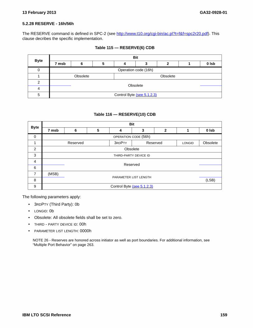
13 February 2013 GA32-0928-01
5.2.28 RESERVE - 16h/56h
The RESERVE command is defined in SPC-2 (see http://www.t10.org/cgi-bin/ac.pl?t=f&f=spc2r20.pdf). This clause decribes the specific implementation.
The following parameters apply:
• 3RDPTY (Third Party): 0b
• LONGID: 0b
• Obsolete: All obsolete fields shall be set to zero.
• THIRD - PARTY DEVICE ID: 00h
• PARAMETER LIST LENGTH: 0000h
NOTE 26 - Reserves are honored across initiator as well as port boundaries. For additional information, see “Multiple Port Behavior” on page 263.
Table 115 — RESERVE(6) CDB
ByteBit
7 msb 6 5 4 3 2 1 0 lsb
0 Operation code (16h)
1 Obsolete Obsolete
2Obsolete
4
5 Control Byte (see 5.1.2.3)
Table 116 — RESERVE(10) CDB
ByteBit
7 msb 6 5 4 3 2 1 0 lsb
0 OPERATION CODE (56h)
1 Reserved 3RDPTY Reserved LONGID Obsolete
2 Obsolete
3 THIRD-PARTY DEVICE ID
4Reserved
6
7 (MSB)PARAMETER LIST LENGTH
8 (LSB)
9 Control Byte (see 5.1.2.3)
IBM LTO SCSI Reference 159

GA32-0928-01 13 February 2013
5.2.29 REWIND - 01h
The Rewind command is defined in SSC (see the latest version at http://www.t10.org/drafts.htm#SCSI3_CMNDSETS). This clause decribes the specific implementation.
The following parameters apply:
• Immed (Immediate):Value Description0b present status when command is completed.1b present status when all buffered data is successfully written to the media.
NOTE 27 - On eServer enabled drives (i.e., The PRODUCT ID returned in Standard Inquiry is "HH LTO Gen x" where "x" is a number), a CHECK CONDITION status with SENSE KEY set to 1h and the additional sense code set to DEGRADED MEDIA (i.e., ASC/ASCQ 8252h) may be returned after completion of the REWIND command if certain conditions are met.
Table 117 — REWIND CDB
ByteBit
7 msb 6 5 4 3 2 1 0 lsb
0 OPERATION CODE (01h)
1 Obsolete Reserved IMMED
2Reserved
4
5 Control Byte (see 5.1.2.3)
160 IBM LTO SCSI Reference

13 February 2013 GA32-0928-01
5.2.30 SECURITY PROTOCOL IN (SPIN) - A2h
The Security Protocol In command is defined in SPC-4 (see the latest version at http://www.t10.org/drafts.htm#SCSI3_CMNDSETS). This clause decribes the specific implementation.
The SECURITY PROTOCOL IN command (see table 118) is:
a) supported in encryption capable drives that are configured for AME-T10 mode (see 4.12); andb) is used to retrieve security protocol information (see 6.8.1) or the results of one or more SECURITY
PROTOCOL OUT commands (see 5.2.31).
The following parameters apply:
• SECURITY PROTOCOL: SPIN (00h[0000h]) - Supported Security Protocols List (see 6.8.1.1 on page 434) lists the supported security protocols.
• SECURITY PROTOCOL SPECIFIC - The contents depend on the protocol specified by the SECURITY PROTOCOL field. The following SPIN pages provide a list of supported SECURITY PROTOCOL SPECIFIC values:
SPIN (00h[0000h]) - Supported Security Protocols List (see 6.8.1.1 on page 434)SPIN (20h[0000h]) - Tape Data Encryption In Support Pages page (see 6.8.2.1 on page 437)SPIN (20h[0001h]) - Tape Data Encryption Out Support Pages page (see 6.8.2.2 on page 438)
• INC_512: 0b
• ALLOCATION LENGTH:
Security Protocol Parameters (SPP) (see 6.8 on page 433) has a listing of all security protocol parameters.
Table 118 — SECURITY PROTOCOL IN - A2h CDB
ByteBit
7 msb 6 5 4 3 2 1 0 lsb
0 OPERATION CODE (A2h)
1 SECURITY PROTOCOL
2SECURITY PROTOCOL SPECIFIC
3
4 inc_512 Reserved
5 Reserved
6 (MSB)Allocation Length
9 (LSB)
10 Reserved
11 Control Byte (see 5.1.2.3)
IBM LTO SCSI Reference 161

GA32-0928-01 13 February 2013
5.2.31 SECURITY PROTOCOL OUT (SPOUT) - B5h
The Security Protocol Out command is defined in SPC-4 (see the latest version at http://www.t10.org/drafts.htm#SCSI3_CMNDSETS). This clause decribes the specific implementation.
The SECURITY PROTOCOL OUT command (see Table 119) is:
a) supported in encryption capable drives that are configured for AME-T10 mode Encryption Control - T10 Standards (see 4.12.2 on page 49); and
b) used to send data to the logical unit. The data sent specifies one or more operations to be performed by the logical unit. The format and function of the operations depends on the contents of the SECURITY PROTOCOL field (see table 119). Depending on the protocol specified by the SECURITY PROTOCOL field, the application client may use the SECURITY PROTOCOL IN command (see 5.2.30) to retrieve data derived from these operations.
NOTE 28 - The operation code, B5h has been recovered from a seldom used media changer (i.e. LUN 1) command (REQUEST VOLUME ELEMENT ADDRESS). If the device driver being used still uses the LUN field of the CDB from SCSI-2 days, this command will be routed to the incorrect LUN. Since the SPOUT command is a DATA OUT type command, whereas the REQUEST VOLUME ELEMENT ADDRESS command is a DATA IN type command this has the potential to cause strange system behaviors.
The following parameters apply:
• SECURITY PROTOCOL
Value Description20h Tape Data Encryption security protocol (see 6.8.3).
• SECURITY PROTOCOL SPECIFIC: The contents depend on the protocol specified by the SECURITY PROTOCOL field.
• INC_512: 0b
• ALLOCATION LENGTH:
Security Protocol Parameters (SPP) (see 6.8 on page 433) has a listing of all security protocol parameters.
Table 119 — SECURITY PROTOCOL OUT B5h CDB
ByteBit
7 msb 6 5 4 3 2 1 0 lsb
0 OPERATION CODE (B5h)
1 SECURITY PROTOCOL
2SECURITY PROTOCOL SPECIFIC
3
4 inc_512 Reserved
5 Reserved
6 (MSB)ALLOCATION LENGTH
9 (LSB)
10 Reserved
11 Control Byte (see 5.1.2.3)
162 IBM LTO SCSI Reference

13 February 2013 GA32-0928-01
5.2.32 SEND DIAGNOSTIC - 1Dh
The SEND DIAGNOSTIC command is defined in SPC (see the latest version at http://www.t10.org/drafts.htm#SCSI3_CMNDSETS). This clause decribes the specific implementation.
After a Send Diagnostic command completes, use the Receive Diagnostic Results command to receive the results.
For diagnostics that produce diagnostic results, the LUN should be reserved to allow the I_T nexus that issued the Send Diagnostic command to issue the Receive Diagnostic Results command before a different I_T nexus clears the results by reading them.
The following parameters apply:
• PF (Page Format): 1b
• SELFTEST:Value Description0b Perform the diagnostic operation specified in the parameter list.1b Perform self test. See 6.2.3 on page 204 for details of this diagnostic.
NOTE 29 - When Self Test is requested, no other diagnostic may be simultaneously requested.
• DEVOFL (Device Off Line):Value Description0b is supported and prohibits any diagnostic operations that may be detected by subsequent
I/O processes.1b is supported and grants permission to the target to perform diagnostic operations that may
affect all the logical units on a target; that is, alteration of reservations, log parameters, or sense data.
x in the diagnostic description indicates that either 0b or 1b may be used with identical effects.
NOTE 30 - DEVOFL and UNITOFL are set by the system. These bits grant permission to the target to perform vendor-specific diagnostic operations on the target that may be visible to attached initiators. Thus, by preventing operations that are not enabled by these bits, the target assists the operating system in protecting its resources.
• UNITOFL (Unit Off Line):Value Description0b is supported and prohibits any diagnostic operations that may be detected by subsequent
I/O processes.1b is supported and grants permission to the target to perform diagnostic operations that may
affect the user medium on the logical unit; for example, write operations to the
Table 120 — SEND DIAGNOSTIC CDB
ByteBit
7 msb 6 5 4 3 2 1 0 lsb
0 OPERATION CODE (1Dh)
1 Obsolete PF Reserved SELFTEST DEVOFL UNITOFL
2 Reserved
3 MSBPARAMETER LIST LENGTH
4 LSB
5 Control Byte (see 5.1.2.3)
IBM LTO SCSI Reference 163

GA32-0928-01 13 February 2013
user-accessible medium, or operations that reposition the medium on sequential access devices.
x in the diagnostic description indicates that either 0b or 1b may be used with identical effects.
• PARAMETER LIST LENGTH: This field specifies the length in bytes of the parameter list that is transferred from the initiator to the target. A parameter list length value of zero specifies that no data is transferred. This condition is not considered an error. If the specified parameter list length results in truncation of one or more pages (PF bit set to 1b), the target returns CHECK CONDITION status with associated sense data of 5/2400 (ILLEGAL REQUEST, INVALID FIELD IN CDB).
Diagnostic Parameters (Diag) (see 6.2 on page 195) has a listing of all diagnostic parameters.
164 IBM LTO SCSI Reference

13 February 2013 GA32-0928-01
5.2.33 SET CAPACITY - 0Bh
The SET CAPACITY command is defined in SSC-4 (see the latest version at http://www.t10.org/drafts.htm#SCSI3_CMNDSETS). This clause decribes the specific implementation.
The SET CAPACITY command sets the available medium for the currently mounted volume to a proportion of the total medium for use. Any excess space shall be unavailable on the medium after successful completion of this command until changed by a new SET CAPACITY command. This change shall persist through power cycles, logical unit resets, I_T nexus losses, and unloading or reloading of the volume.
If no volume is loaded, then the command is terminated with CHECK CONDITION status. The sense key is set to NOT READY, and the additional sense code is set to MEDIUM NOT PRESENT.
The SET CAPACITY command is accepted only when the medium is at beginning-of-partition 0 (BOP 0). If the medium is logically at any other position, the command is rejected with CHECK CONDITION status. The sense key is set to ILLEGAL REQUEST and the additional sense code is set to POSITION PAST BEGINNING OF MEDIUM.
A valid SET CAPACITY command causes all data and partitioning information on the entire physical volume to be lost. If the partitioning information changes, a unit attention condition is established for all initiators with the additional sense code set to MODE PARAMETERS CHANGED.
The following paramters apply:
• IMMED (immediate): Value Description0b present status when command is completed.1b present status when the command descriptor block has been validated all buffered data, if
any, is successfully written to the medium.
• MEDIUM FOR USE PROPORTION VALUE (MFUPV): The portion of the total medium to be made available for use. This field is the numerator to a fraction that has a denominator of 65 535 (FFFFh). The resulting available capacity on the tape is equal to the total unscaled tape capacity multiplied by this fraction.
This device may round up the capacity to the next highest supported value. This rounding is not consid-ered an error and is not reported. If the MEDIUM FOR USE PROPORTION VALUE does not meet the ranges specified in table 122 then CHECK CONDITION status is returned with ILLEGAL FIELD IN CDB
Table 121 — SET CAPACITY CDB
ByteBit
7 6 5 4 3 2 1 0
0 OPERATION CODE (0Bh)
1 Reserved IMMED
2 Reserved
3 (MSB)MEDIUM FOR USE PROPORTION VALUE
4 (LSB)
5 Control Byte (see 5.1.2.3)
MFUPV65535
---------------------- TotalUnscaledTapeCapacity× ResultingAvailableCapacity=
IBM LTO SCSI Reference 165

GA32-0928-01 13 February 2013
(5/2400h).
WARNING WARNINGIf the Capacity Proportion is increased it is possible that a debris dump may exist at the previous logical end of
WARNING WARNING
medium. This may cause a defect when attempting to write through that area.
NOTE 31 - The MEDIUM FOR USE PROPORTION VALUE relates to the physical proportion of the medium that is available for use to record logical objects and is not limited by the maximum number of logical objects that the device server is capable of supporting. This maintains the orthogonality between the volume and the logical unit that exists due to volumes being transferred to logical units that may support a different number of logical objects.
Table 122 — MEDIUM FOR USE PROPORTION VALUE and resultant capacity
CartridgeMinimum
MEDIUM FOR USE PROPORTION VALUE
Resultant Approximate
MEDIUM FOR USE PROPORTION VALUE
Maximum Capacity
Ultrium 4 123Dh 52 GB 800 GB
Ultrium 5 0FD8h 92 GB 1500 GB
Ultrium 6 0FD8h 154 GB 2500 GB
Note - Available and total tape capacities are approximate values that may be affected by defects which reduce the actual available capacity of the tape. Other factors, such as compression and block packing, may also affect available capacity.
166 IBM LTO SCSI Reference

13 February 2013 GA32-0928-01
5.2.34 SET TIMESTAMP - A4h[0Fh]
The SET TIMESTAMP command is defined in SPC-4 (see the latest version at http://www.t10.org/drafts.htm#SCSI3_CMNDSETS). This clause decribes the specific implementation.
The SET TIMESTAMP command (see table 123) requests the drive to initialize the timestamp (see 4.14), if the SCSIP bit is set to one or the TCMOS bit is set to one in MP 0Ah[01h]: Control Extension (see 6.6.8 on page 372). If the SCSIP bit is set to zero, the SET TIMESTAMP command is terminated with CHECK CONDITION status, with the sense key set to ILLEGAL REQUEST, and the additional sense code set to INVALID FIELD IN CDB.
The following paramters apply:
• PARAMETER LIST LENGTH: The length in bytes of the SET TIMESTAMP parameters that is transferred from the application client to the device server. A PARAMETER LIST LENGTH of zero indicates that no data is trans-ferred, and that no change is made to the timestamp.
5.2.34.1 SET TIMESTAMP Parameter List
The format for the parameter data for the SET TIMESTAMP command is shown in table 124.
The definition of the parameters follows:
Byte Description
0-3 Reserved4-9 TIMESTAMP: The initial value of the timestamp in the format defined in Device Clocks (see 4.14 on
page 56). The timestamp should be the number of milliseconds that have elapsed since midnight, 1
Table 123 — SET TIMESTAMP CDB
ByteBit
7 6 5 4 3 2 1 0
0 OPERATION CODE (A4h)
1 Reserved SERVICE ACTION (0Fh)
2Reserved
5
6 (MSB)PARAMETER LIST LENGTH
9 (LSB)
10 Reserved
11 Control Byte (see 5.1.2.3)
Table 124 — SET TIMESTAMP parameter list format
ByteBit
7 6 5 4 3 2 1 0
0Reserved
3
4 (MSB)TIMESTAMP
9 (LSB)
10Reserved
11
IBM LTO SCSI Reference 167

GA32-0928-01 13 February 2013
January 1970 UT. If the high order byte in the TIMESTAMP field is greater than F0h, the command isterminated with CHECK CONDITION status, with the sense key set to ILLEGAL REQUEST, and theadditional sense code set to INVALID FIELD IN PARAMETER LIST.
10-11 Reserved
On successful completion of a SET TIMESTAMP command the drive generates a UNIT ATTENTION condition for the initiator port associated with every I_T nexus except the I_T nexus on which the SET TIMESTAMP command was received, with the additional sense code set to TIMESTAMP CHANGED.
168 IBM LTO SCSI Reference

13 February 2013 GA32-0928-01
5.2.35 SPACE (6/16) - 11h/91h
The Space commands are defined in SSC (see the latest version at http://www.t10.org/drafts.htm#SCSI3_CMNDSETS). This clause decribes the specific implementation.
The Space command is implemented similar to the Locate command, causing the tape to move at maximum speed when appropriate.
The Space(16) command (see table 126), operates identically to the Space(6) command, but allows specifying a Count field up to eight bytes in length.
This command is newly added to the standards. The only exceptions to SSC-3 for this command are that the explicit command set is not supported and the list of values supported in the Code field.
The following parameters apply:
• CODE: Specifies the type of logical objects to be spaced over or the termination point of the operation.Value Description0h Blocks:
If a filemark is encountered while spacing over logical blocks, the command is terminated. CHECK CONDITION status is returned, and the FILEMARK and VALID bits are set to one in the sense data. The sense key is set to NO SENSE and the additional sense code is set to FILEMARK DETECTED. The INFORMATION field is set to the number of logical objects to be spaced over minus the actual number of logical objects spaced over not including the filemark. The logical position is on the end-of-partition side of the filemark if movement was
Table 125 — Space (6) CDB
ByteBit
7 msb 6 5 4 3 2 1 0 lsb
0 Operation code (11h)
1 Obsolete (LUN) Reserved Code
2 MSBCount
4 LSB
5 Control Byte (see 5.1.2.3)
Table 126 — Space(16) CDB
ByteBit
7 msb 6 5 4 3 2 1 0 lsb
0 Operation Code (91h)
1 Reserved Code
2Reserved
3
4 (MSB)Count
11 (LSB)
12 (MSB)Parameter Length (0000h)
13
14 Reserved
15 Control Byte (see 5.1.2.3)
IBM LTO SCSI Reference 169

GA32-0928-01 13 February 2013
in the forward direction and on the beginning-of-partition side of the filemark if movement was in the reverse direction.
1h Filemarks3h End of Dataothers Reserved
• COUNT: A value in two’s complement notation specifying the number of logical objects to be spaced over and the direction of movement. If the CODE field is set to 3h (i.e., End-of-data), then the COUNT field is ignored.
When spacing over logical objects, the magnitude of the value in the COUNT field specifies the number of logical objects to be spaced over in the current partition and the sign of the value in the COUNT field speci-fies the direction of movement.
If the COUNT field contains a positive value N and the CODE field does not contain 3h (i.e., end-of-data) then the device server positions in the forward direction (i.e., toward end-of-partition) over N logical objects ending on the end-of-partition side of the last logical object.
If the COUNT field contains a negative value -N, in two's complement notation, and the CODE field does not contain 3h (i.e., end-of-data) then the device server positions in the reverse direction (i.e., toward begin-ning-of-partition) over N logical objects ending on the beginning-of-partition side of the last logical object.
If the drive encounters End-of-Data (EOD) while processing this command, the command is terminated at the EOD position and CHECK CONDITION status is returned with associated sense data of 8/0005 (BLANK CHECK, END-OF-DATA DETECTED).
• PARAMETER LENGTH: 0000h
170 IBM LTO SCSI Reference

13 February 2013 GA32-0928-01
5.2.36 TEST UNIT READY - 00h
The TEST UNIT READY command is defined in SPC (see the latest version at http://www.t10.org/drafts.htm#SCSI3_CMNDSETS). This clause decribes the specific implementation.
The TEST UNIT READY command reports when there is a medium in the drive that is ready to accept medium access commands. If a medium is loaded and a problem is detected that does not force the automatic ejection of the medium, GOOD status will still be returned to the TEST UNIT READY command. Whatever error is detected will be returned in response to the next medium access command.
Table 127 — Table 355. TEST UNIT READY CDB
ByteBit
7 6 5 4 3 2 1 0
0 Operation Code (00h)
1 Obsolete Reserved
2 Reserved
3 Reserved
4 Reserved
5 Control Byte (see 5.1.2.3)
IBM LTO SCSI Reference 171

GA32-0928-01 13 February 2013
5.2.37 VERIFY(6) - 13h
The VERIFY command is defined in SSC (see the latest version at http://www.t10.org/drafts.htm#SCSI3_CMNDSETS). This clause decribes the specific implementation. The VERIFY(6) command (see table 128) requests that the device server verify one or more logical block(s) or one or more logical file(s) beginning at the current logical position. Prior to performing the verify operation, the device server performs a synchronize operation (see 4.2.11).
The following parameters apply:
• VTE - If the verify to end-of-data (VTE) bit is set to one, then all logical blocks shall be verified between the current position and EOD (see 4.5.7). The behavior related to encrypted logical blocks is the same as if they are read with a READ command. The logical position upon successful completion of a verify with the VTE bit set to one shall be at EOD. If the VTE bit is set to one and the verification of a logical block fails, then the command shall terminate with CHECK CONDITION status, the SENSE VALID bit shall be set to zero, the INFORMATION field shall be set to zero, and the sense key, sense code, and additional sense code shall be set the same as it would be on a read. Upon termination, the medium shall be positioned after the logical block on which the verification failed (i.e., end-of-partition side). If the VTE bit is set to one, then the BYTCMP bit and the VBF bit shall be set to zero. If the VTE bit is set to one, then the VERIFICATION LENGTH field shall be ignored. If the VTE bit is set to one and the FIXED bit is set to one, then the length of each log-ical block shall be verified to be the current block length reported in the mode parameters block descriptor. If the VTE bit is set to one and the FIXED bit is set to zero, then the length of each logical block shall not be verified. If the VTE bit is set to zero, then a verify to EOD is not requested.
• VLBPM - If the verify logical block protection method (VLBPM) bit is set to one then the verification being per-formed also includes a verification that each logical block uses the logical block protection method speci-fied in the Control Data Protection mode page. If the VLBPM bit is set to one and the verification fails because a logical block did not use the logical block protection method specified by the Control Data Pro-tection mode page, then the device server terminates the command with CHECK CONDITION status, with the sense key set to MISCOMPARE and the additional sense code set to LOGICAL BLOCK PROTEC-TION METHOD ERROR. Upon termination, the medium is positioned after the logical block on which the verification failed (end-of-partition side). If the VLBPM bit is set to zero then the verification being performed does not require a verification that each logical block uses the logical block protection method specified in the Control Data Protection mode page. If a logical block is encrypted, then the behavior is the same as attempting to read an ecnrypted logical block with the READ command.
• VBF - If the verify by filemarks (VBF) bit is set to one, then the VERIFICATION LENGTH field contains a count of
filemarks to be traversed. All logical blocks starting at the current position and continuing to the nth file-mark, where n is the value in the VERIFICATION LENGTH field shall be verified (see 4.5.6). The behavior related to encrypted logical blocks is the same as it is for a READ command. The logical position upon
successful completion of a verify with the VBF bit set to one shall be after the nth filemark. If the VBF bit is set to one and the verification of a logical block fails, then the command shall terminate with CHECK CON-DITION status, the SENSE VALID bit shall be set to one, the INFORMATION field shall be set to the requested verification length minus the actual number of filemarks successfully traversed, and the sense key, sense code, and additional sense code values shall be the same as for a READ ocmmand. Upon termination, the medium shall be positioned after the logical block on which the verification failed (end-of-partition side). If
Table 128 — VERIFY(6) CDB
ByteBit
7 msb 6 5 4 3 2 1 0 lsb
0 OPERATION CODE (13h)
1 Reserved VTE VLBPM VBF IMMED BYTCMP FIXED
2 (MSB)VERIFICATION LENGTH
4 (LSB)
5 Control Byte (see 5.1.2.3)
172 IBM LTO SCSI Reference

13 February 2013 GA32-0928-01
the VBF bit is set to one, then the BYTCMP bit and the VTE bit shall be set to zero. If the VBF bit is set to one and the FIXED bit is set to one, then the length of each logical block shall be verified to be the current block length reported in the mode parameters block descriptor. If the VBF bit is set to one and the FIXED bit is set to zero, then the length of each logical block shall not be verified. If the VBF bit is set to zero, then the VER-
IFICATION LENGTH field does not contain a count of filemarks to be traversed.
• IMMED: 0bValue Description0b The command does not return status until the verify operation has completed.1b Status is returned as soon as the command descriptor block has been validated.
• BYTCMP: 0b
The verification is a verification of logical blocks on the medium (e.g., CRC, ECC). No data is transferred from the application client to the device server.
• FIXED (see 4.7)
• VERIFICATION LENGTH (see 4.7): The amount of data to verify in, logical files, logical blocks or bytes, as specified by the VBF bit and the FIXED bit. If the VTE bit is one, then the VERIFICATION LENGTH field shall be ignored. If the VERIFICATION LENGTH field is zero and the VTE bit is zero, then no data is verified and the cur-rent logical position is not changed. This condition is not considered an error.
The VERIFY(6) command terminates as follows:
a) when conditions related to encryption are met;b) when the verification length has been satisfied and the VTE bit is zero;c) when an incorrect-length logical block is encountered;d) when a filemark is encountered and the VBF bit and VTE bit are zero;e) when end-of-data is encountered;f) when the end-of-partition is encountered;g) when early-warning is encountered (if the REW bit is one in the Device Configuration mode page) and
the VTE bit is zero;h) when the logical block protection method used by the logical block is not the logical block protection
method specified in the Control Data Protection mode page and the VLBPM bit is one; ori) when an unrecoverable read error is encountered.
General Read-Type Handling (see 4.8.1 on page 42) provides additional information.
IBM LTO SCSI Reference 173

GA32-0928-01 13 February 2013
5.2.38 WRITE - 0Ah
The WRITE command is defined in SSC (see the latest version at http://www.t10.org/drafts.htm#SCSI3_CMNDSETS). This clause decribes the specific implementation.
The following parameters apply:
• FIXED (see 4.7)
• TRANSFER LENGTH (see 4.7)
If the logical object identifier of the current position on medium is greater than FFFFFF00h and less than FFFFFFF0h, then rules for Logical EOM processing are applied. If the logical object identifier of the current position on medium is greater than or equal to FFFFFFF0h, rules for physical end of partition processing are applied.
Table 129 — WRITE CDB
ByteBit
7 msb 6 5 4 3 2 1 0 lsb
0 OPERATION CODE (0Ah)
1 Obsolete (LUN) Reserved FIXED
2 MSBTRANSFER LENGTH
4 LSB
5 Control Byte (see 5.1.2.3)
174 IBM LTO SCSI Reference

13 February 2013 GA32-0928-01
5.2.39 WRITE ATTRIBUTE - 8Dh
The WRITE ATTRIBUTE command is defined in SPC-4 (see the latest version at http://www.t10.org/drafts.htm#SCSI3_CMNDSETS). This clause decribes the specific implementation.
The WRITE ATTRIBUTE command (see table 130) allows an application client to write attributes to medium auxiliary memory. The READ ATTRIBUTE command (see 5.2.13) is used to read these attribute. Application clients should issue READ ATTRIBUTE commands prior to using this command to discover device server support for medium auxiliary memory.
The following parameters apply:
Byte Description
0 OPERATION CODE (8Dh)1 Byte 1
Bit Description7-1 Reserved0 WTC - Write-through cache
Value Description0b The attributes in the parameter list may be cached.1b The attributes in the parameter list shall be synchronized with the medium auxil-
iary memory during the processing of the WRITE ATTRIBUTE command and GOOD status shall not be returned until the attributes have been synchronized with the medium auxiliary memory.
2-4 Reserved5 VOLUME NUMBER (00h)6 Reserved7 PARTITION NUMBER - The number of the partition to which these attributes belong. This shall be zero if
there is only one partition on the volume.8-9 Reserved10-13 PARAMETER LIST LENGTH - The length in bytes of the parameter list contained in the Data-Out Buffer. A
parameter list length of zero specifies that no parameter data is present; this shall not be considered anerror. If the parameter list length results in the truncation of an attribute, the WRITE ATTRIBUTE
Table 130 — WRITE ATTRIBUTE CDB
BitByte
7 6 5 4 3 2 1 0
0 OPERATION CODE (8Dh)
1 Reserved WTC
2Reserved
4
5 VOLUME NUMBER (00h)
6 Reserved
7 PARTITION NUMBER
8Reserved
9
10 (MSB)PARAMETER LIST LENGTH
13 (LSB)
14 Reserved
15 Control Byte (see 5.1.2.3)
IBM LTO SCSI Reference 175

GA32-0928-01 13 February 2013
command is terminated with CHECK CONDITION status, with the sense key set to ILLEGAL REQUEST,and the additional sense code set to PARAMETER LIST LENGTH ERROR.
14 Reserved15 CONTROL (see 5.1.2.3)
The parameter list shall have the format shown in table 131. Attributes shall be sent in ascending numerical order. If the attributes are not in order, then no attributes are changed and the WRITE ATTRIBUTE command is terminated with CHECK CONDITION status, with the sense key set to ILLEGAL REQUEST, and the additional sense code set to INVALID FIELD IN PARAMETER LIST.
The PARAMETER DATA LENGTH field should contain the number of bytes of attribute data and shall be ignored by the device server.
The format of the attributes is described in “READ ATTRIBUTE” on page 252.
If there is not enough space to write the attributes to the medium auxiliary memory, then no attributes shall be changed and the WRITE ATTRIBUTE command shall be terminated with CHECK CONDITION status, with the sense key set to ILLEGAL REQUEST, and the additional sense code set to AUXILIARY MEMORY OUT OF SPACE.
If the medium auxiliary memory is not accessible because there is no medium present, then no attributes shall be changed and the WRITE ATTRIBUTE command shall be terminated with CHECK CONDITION status, with the sense key set to NOT READY, and the additional sense code set to MEDIUM NOT PRESENT.
If the medium is present but the medium auxiliary memory is not accessible, then no attributes shall be changed and the WRITE ATTRIBUTE command shall be terminated with CHECK CONDITION status, with the sense key set to MEDIUM ERROR, and the additional sense code set to LOGICAL UNIT NOT READY, AUXILIARY MEMORY NOT ACCESSIBLE.
If the medium auxiliary memory is not operational (e.g., bad checksum), the WRITE ATTRIBUTE command shall be terminated with CHECK CONDITION status, with the sense key set to MEDIUM ERROR, and the additional sense code set to AUXILIARY MEMORY WRITE ERROR.
If the WRITE ATTRIBUTE command parameter data contains an attribute with an ATTRIBUTE LENGTH field set to zero, then one of the following actions shall occur:
a) if the attribute state is unsupported or read only (see 4.17), then no attributes shall be changed and the WRITE ATTRIBUTE command shall be terminated with CHECK CONDITION status, with the sense key set to ILLEGAL REQUEST, and the additional sense code set to INVALID FIELD IN PARAMETER LIST;
b) if the attribute state is read/write, the attribute shall be changed to the nonexistent state. This attribute shall not be returned in response to a READ ATTRIBUTE command and not be reported by the READ ATTRIBUTE command with ATTRIBUTE LIST service action; or
c) if the attribute state is nonexistent, the attribute in the WRITE ATTRIBUTE command parameter list shall be ignored; this shall not be considered an error.
Table 131 — WRITE ATTRIBUTE parameter list format
BitByte
7 6 5 4 3 2 1 0
0 (MSB)PARAMETER DATA LENGTH (n-3)
3 (LSB)
Attribute(s)
4Attribute 0 (see 6.5)
…
Attribute x (see 6.5)n
176 IBM LTO SCSI Reference

13 February 2013 GA32-0928-01
No attributes shall be changed, the WRITE ATTRIBUTE command shall be terminated with CHECK CONDITION status, with the sense key set to ILLEGAL REQUEST, and the additional sense code set to INVALID FIELD IN PARAMETER LIST if the parameter data contains any of the following:
a) an attempt to change an attribute in the read only state;b) an attribute with incorrect ATTRIBUTE LENGTH field contents; orc) an attribute with unsupported ATTRIBUTE VALUE field contents.
IBM LTO SCSI Reference 177
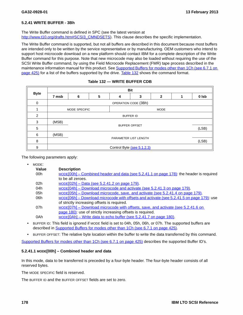
GA32-0928-01 13 February 2013
5.2.41 WRITE BUFFER - 3Bh
The Write Buffer command is defined in SPC (see the latest version at http://www.t10.org/drafts.htm#SCSI3_CMNDSETS). This clause describes the specific implementation.
The Write Buffer command is supported, but not all buffers are described in this document because most buffers are intended only to be written by the service representative or by manufacturing. OEM customers who intend to support host microcode download on a new platform should contact IBM for a complete description of the Write Buffer command for this purpose. Note that new microcode may also be loaded without requiring the use of the SCSI Write Buffer command, by using the Field Microcode Replacement (FMR) tape process described in the maintenance information manual for this product. See Supported Buffers for modes other than 1Ch (see 6.7.1 on page 425) for a list of the buffers supported by the drive. Table 132 shows the command format.
The following parameters apply:
• MODE:Value Description00h MODE[00h] – Combined header and data (see 5.2.41.1 on page 178): the header is required
to be all zeroes.02h MODE[02h] – Data (see 5.2.41.2 on page 179).04h MODE[04h] – Download microcode and activate (see 5.2.41.3 on page 179).05h MODE[05h] – Download microcode, save, and activate (see 5.2.41.4 on page 179).06h MODE[06h] – Download microcode with offsets and activate (see 5.2.41.5 on page 179): use
of strictly increasing offsets is required.07h MODE[07h] – Download microcode with offsets, save, and activate (see 5.2.41.6 on
page 180): use of strictly increasing offsets is required.0Ah MODE[0Ah] – Write data to echo buffer (see 5.2.41.7 on page 180).
• BUFFER ID: This field is ignored if MODE field is set to 04h, 05h, 06h, or 07h. The supported buffers are described in Supported Buffers for modes other than 1Ch (see 6.7.1 on page 425).
• BUFFER OFFSET: The relative byte location within the buffer to write the data transferred by this command.
Supported Buffers for modes other than 1Ch (see 6.7.1 on page 425) describes the supported Buffer ID’s.
5.2.41.1 MODE[00h] – Combined header and data
In this mode, data to be transferred is preceded by a four-byte header. The four-byte header consists of all reserved bytes.
The MODE SPECIFIC field is reserved.
The BUFFER ID and the BUFFER OFFSET fields are set to zero.
Table 132 — WRITE BUFFER CDB
ByteBit
7 msb 6 5 4 3 2 1 0 lsb
0 OPERATION CODE (3Bh)
1 MODE SPECIFIC MODE
2 BUFFER ID
3 (MSB)BUFFER OFFSET
5 (LSB)
6 (MSB)PARAMETER LIST LENGTH
8 (LSB)
9 Control Byte (see 5.1.2.3)
178 IBM LTO SCSI Reference

13 February 2013 GA32-0928-01
The PARAMETER LIST LENGTH field specifies the maximum number of bytes that are transferred from the Data-Out Buffer. This number includes four bytes of header, so the data length to be stored in the device’s buffer is parameter list length minus four. The application client should attempt to ensure that the parameter list length is not greater than four plus the BUFFER CAPACITY field value (see 5.2.17.3) that is returned in the header of the READ BUFFER command combined header and data mode (i.e., 0h). If the parameter list length exceeds the buffer capacity, the command is terminated with CHECK CONDITION status, with the sense key set to ILLEGAL REQUEST, and the additional sense code set to INVALID FIELD IN CDB.
5.2.41.2 MODE[02h] – Data
In this mode, the Data-Out Buffer contains buffer data destined for the device. The BUFFER ID field identifies a specific buffer within the device. The vendor assigns buffer ID codes to buffers within the device. If an unsupported buffer ID code is selected, the command is terminated with CHECK CONDITION status, with the sense key set to ILLEGAL REQUEST, and the additional sense code set to INVALID FIELD IN CDB.
The MODE SPECIFIC field is reserved.
The BUFFER OFFSET field specifies the location in the buffer to which the data is written. The application client should conform to the offset boundary requirements returned in the READ BUFFER descriptor (see 5.2.17.3). If the device is unable to process the specified buffer offset, the command is terminated with CHECK CONDITION status, with the sense key set to ILLEGAL REQUEST, and the additional sense code set to INVALID FIELD IN CDB.
The PARAMETER LIST LENGTH field specifies the maximum number of bytes that are transferred from the Data-Out Buffer to be stored in the specified buffer beginning at the buffer offset. The application client should attempt to ensure that the parameter list length plus the buffer offset does not exceed the capacity of the specified buffer. The capacity of the buffer is indicated by the BUFFER CAPACITY field in the READ BUFFER descriptor (see 5.2.17.3). If the BUFFER OFFSET and PARAMETER LIST LENGTH fields specify a transfer in excess of the buffer capacity, the command is terminated with CHECK CONDITION status, with the sense key set to ILLEGAL REQUEST, and the additional sense code set to INVALID FIELD IN CDB.
5.2.41.3 MODE[04h] – Download microcode and activate
In this mode, microcode is transferred to the device and activated.
The MODE SPECIFIC field is reserved.
The BUFFER ID field, BUFFER OFFSET field, and PARAMETER LIST LENGTH field are vendor specific.
5.2.41.4 MODE[05h] – Download microcode, save, and activate
In this mode, microcode is transferred to the device, saved to nonvolatile storage, and activated based on the setting of the ACTIVATE MICROCODE field in the Extended INQUIRY VPD page.
The MODE SPECIFIC field is reserved.
The BUFFER ID field, BUFFER OFFSET field, and PARAMETER LIST LENGTH field are vendor specific.
5.2.41.5 MODE[06h] – Download microcode with offsets and activate
In this mode, microcode is transferred to the device using one or more WRITE BUFFER commands and activated.
The MODE SPECIFIC field is reserved.
The BUFFER ID field specifies a buffer within the device. If an unsupported buffer ID code is specified, the command is terminated with CHECK CONDITION status, with the sense key set to ILLEGAL REQUEST, and the additional sense code set to INVALID FIELD IN CDB.
The BUFFER OFFSET field specifies the location in the buffer to which the microcode is written. The application client shall send commands that conform to the offset boundary requirements returned in the READ BUFFER descriptor (see 5.2.17.3). If the device is unable to process the specified buffer offset, the command is terminated
IBM LTO SCSI Reference 179

GA32-0928-01 13 February 2013
with CHECK CONDITION status, with the sense key set to ILLEGAL REQUEST, and the additional sense code set to INVALID FIELD IN CDB.
The PARAMETER LIST LENGTH field specifies the maximum number of bytes that are present in the Data-Out Buffer to be stored in the specified buffer beginning at the buffer offset. The application client should ensure that the parameter list length plus the buffer offset does not exceed the capacity of the specified buffer. If the BUFFER OFFSET and PARAMETER LIST LENGTH fields specify a transfer in excess of the buffer capacity, then the command is terminated with CHECK CONDITION status, with the sense key set to ILLEGAL REQUEST, and the additional sense code set to INVALID FIELD IN CDB.
5.2.41.6 MODE[07h] – Download microcode with offsets, save, and activate
In this mode, microcode is transferred to the device using one or more WRITE BUFFER commands, saved to nonvolatile storage, and activated based on the setting of the ACTIVATE MICROCODE field in the Extended INQUIRY VPD page.
The BUFFER ID field, BUFFER OFFSET field, and PARAMETER LIST LENGTH field are defined in the download microcode with offsets mode (see 5.2.41.5).
5.2.41.7 MODE[0Ah] – Write data to echo buffer
In this mode the device transfers data from the application client and stores it in an echo buffer. An echo buffer is assigned in the same manner by the device as it would for a write operation. Data is sent aligned on four-byte boundaries.
The BUFFER ID and BUFFER OFFSET fields are ignored in this mode.
Upon successful completion of a WRITE BUFFER command the data is preserved in the echo buffer unless there is an intervening command to any device in which case the data may be changed.
The PARAMETER LIST LENGTH field specifies the maximum number of bytes that are transferred from the Data-Out Buffer to be stored in the echo buffer. The application client should ensure that the parameter list length does not exceed the capacity of the echo buffer. The capacity of the echo buffer is indicated by the BUFFER CAPACITY field in the READ BUFFER echo buffer descriptor (see 5.2.17.6). If the PARAMETER LIST LENGTH field specifies a transfer in excess of the buffer capacity, the command is terminated with CHECK CONDITION status, with the sense key set to ILLEGAL REQUEST, and the additional sense code set to INVALID FIELD IN CDB.
180 IBM LTO SCSI Reference

13 February 2013 GA32-0928-01
5.2.42 WRITE DYNAMIC RUNTIME ATTRIBUTE - D2h
The WRITE DYNAMIC RUNTIME ATTRIBUTE command has the format in table 133.
5.2.42.1 WRITE DYNAMIC RUNTIME ATTRIBUTE parameter list
The parameter list shall have the format shown in table 134. Attributes that may be changed in a WRITE DYNAMIC RUNTIME ATTRIBUTE command are the initiator type attributes listed in 6.1.2.4.
If an attribute that is not an initiator type is sent in the list of attributes, then this shall not be considered an error, the attribute shall be ignored, and the remaining attributes shall be processed normally.
The device server shall process attributes in the order received. Attributes shall be sent in ascending order by attribute identifier. If the attributes are not in order, then no attributes shall be changed and the WRITE DYNAMIC RUNTIME ATTRIBUTE command shall be terminated with CHECK CONDITION status, with the sense key set to ILLEGAL REQUEST, and the additional sense code set to INVALID FIELD IN PARAMETER LIST.
If an attribute that requires creation of that attribute is sent in the list of attributes and there are no available resources to create that attribute, then all attributes for which there are resources shall be changed and the WRITE DYNAMIC RUNTIME ATTRIBUTE command shall be terminated with a CHECK CONDITION with the sense code set to RECOVERED ERROR and the additional sense code set to INSUFFICIENT RESOURCES (i.e., 1h / 5503h).
Table 133 — WRITE DYNAMIC RUNTIME ATTRIBUTE command
BitByte
7 6 5 4 3 2 1 0
0 OPERATION CODE (D2h)
1
Reserved…
5
6 (MSB)
PARAMETER LIST LENGTH…
9 (LSB)
10 Reserved
11 Control
Table 134 — WRITE DYNAMIC RUNTIME ATTRIBUTE parameter list
BitByte
7 6 5 4 3 2 1 0
0
RESERVED…
7
Attribute(s) (see 6.1)
8
Attribute 0 (see 6.1.1)…
Attribute x (see 6.1.1)…
n
IBM LTO SCSI Reference 181

GA32-0928-01 13 February 2013
If the WRITE DYNAMIC RUNTIME ATTRIBUTE command parameter data contains an attribute with an ATTRIBUTE LENGTH field (see 6.1.1) set to zero, then one of the following actions shall occur:
a) if the attribute state is unsupported or read only (see 6.1.1), then the attribute shall not be changed and the WRITE DYNAMIC RUNTIME ATTRIBUTE command shall continue processing normally; this shall not be considered an error;
b) if the attribute state is read/write, the attribute shall be changed to the nonexistent state. This attribute shall not be returned in response to a READ DYNAMIC RUNTIME ATTRIBUTE command; or
c) if the attribute state is nonexistent, the attribute in the WRITE ATTRIBUTE command parameter list shall be ignored; this shall not be considered an error.
If the WRITE DYNAMIC RUNTIME ATTRIBUTE command parameter data contains an attribute with an ATTRIBUTE LENGTH set to a non-zero value other than that specified in 6.1.2.4, then one of the following actions shall occur:
a) if the FORMAT is not ASCII, then the attribute shall be ignored; orb) if the FORMAT is ASCII, then the attribute shall be:
A) truncated to the length specified in 6.1.2.4; orB) ignored.
If the parameter list length results in the truncation of an attribute, the command shall be processed normally but the truncated attribute shall be ignored.
182 IBM LTO SCSI Reference

13 February 2013 GA32-0928-01
5.2.43 WRITE FILEMARKS - 10h
The Write Filemarks command is defined in SSC (see the latest version at http://www.t10.org/drafts.htm#SCSI3_CMNDSETS). This clause decribes the specific implementation.
The following parameters apply:
• IMMED (Immediate):Value Description0b present status when command is completed.1b present status when command is verified.
• FILEMARK COUNT: The number of filemarks to be written.
The initiator may issue a WRITE FILEMARKS command with the IMMED bit set to 0b and the FILEMARK COUNT set to zero to ensure that all buffered data and filemarks are successfully written to the medium (synchronized).
If the logical object identifier of the current position on medium is:
a) greater than FFFFFF00h and less than FFFFFFF0h, then rules for Logical EOM processing are applied;b) greater than or equal to FFFFFFF0h, then rules for physical end of partition processing are applied.
A WRITE FILEMARK with FILEMARK COUNT set to zero when there is no data in the buffer to be synchronized always returns GOOD Status even if the volume is a WORM volume and:
a) the media is not at a writable location; orb) the WORM volume has been tampered with.
On eServer enabled drives, the msb of the vendor specific field in the control byte (i.e., bit 7) is ignored.
Table 135 — WRITE FILEMARKS CDB
ByteBit
7 msb 6 5 4 3 2 1 0 lsb
0 OPERATION CODE (10h)
1 Obsolete Reserved Obsolete IMMED
2 (MSB)FILEMARK COUNT
4 (LSB)
5 Control Byte (see 5.1.2.3)
IBM LTO SCSI Reference 183

GA32-0928-01 13 February 2013
184 IBM LTO SCSI Reference

13 February 2013 GA32-0928-01
6. Parameters for SCSI Commands
This clause describes the parameters used in SCSI commands that are supported on LUN 0.
Parameters are described in a “term-definition” format. In this format, the bits or bytes to be described are highlighted and listed on the left. The definition for the bits or bytes is to the right (not highlighted).
The following is a list of abbreviations used to describe the various parameters referenced in this document as well as a reference to the parameter clause in which those specific parameters are defined:
Term DescriptionDaig Diagnostic Parameters (Diag) (see 6.2 on page 195)IP Inquiry Vital Product Data Parameters (IP) (see 6.3 on page 241)LP Log Parameters (LP) (see 6.4 on page 269)MAM Medium auxiliary memory attributes (MAM) (see 6.5 on page 349)MP Mode Parameters (MP) (see 6.6 on page 359)RB Read/Write Buffers (RB) (see 6.7 on page 425)SPP Security Protocol Parameters (SPP) (see 6.8 on page 433)
IBM LTO SCSI Reference 185

GA32-0928-01 13 February 2013
186 IBM LTO SCSI Reference

13 February 2013 GA32-0928-01
6.1 Dynamic runtime attributes (DRA)
6.1.1 Attribute format
Each dynamic runtime attribute shall be communicated between the application client and device server in the format shown in table 136. This format shall be used in the parameter data for the WRITE DYNAMIC RUNTIME ATTRIBUTE command (see 5.2.42) and the READ DYNAMIC RUNTIME ATTRIBUTE command (see 5.2.18). The attribute format in this standard implies nothing about the physical representation of an attribute in memory.
The I_T NEXUS INDEX field contains an index associated to the I_T_L nexus by the device server. How the I_T nexus index is maintained is not specified by this standard. The I_T nexus index association may change from one command to another. On a read the value of 0000h in the I_T NEXUS INDEX field indicates that there is no I_T_L nexus associated with the attribute specified by the ATTRIBUTE IDENTIFIER field. The device server shall set the I_T NEXUS INDEX field to 0000h in the logical unit type attributes. On a write the I_T NEXUS INDEX field should be set to 0000h by the application client and the device server shall ignore the value and fill in the I_T NEXUS INDEX field of the stored attribute with the value of the associated I_T_L nexus through which the command arrived. A value of FFFFh is reserved.
The ATTRIBUTE IDENTIFIER field contains a code value identifying the attribute (see 6.1.2).
The READ ONLY bit indicates whether the attribute is in the read only state (see 6.1.1). If an attribute is not in the non-existent state or the unsupported state and the READ ONLY bit is set to one, the attribute is in the Read Only state. If an attribute is not in the non-existent state or the unsupported state and the READ ONLY bit is set to zero, then the attribute is in the Read/Write state.
The FORMAT field (see table 137) specifies the format of the data in the ATTRIBUTE VALUE field.
The ATTRIBUTE LENGTH field specifies the length in bytes of the ATTRIBUTE VALUE field. If the ATTRIBUTE LENGTH field is set to zero, then there is no ATTRIBUTE VALUE field.
The ATTRIBUTE VALUE field contains the current value, for the READ DYNAMIC RUNTIME ATTRIBUTE command (see 5.2.18), or intended value, for the WRITE DYNAMIC RUNTIME ATTRIBUTE command (see 5.2.42), of the
Table 136 — DRA ATTRIBUTE format
BitByte
7 6 5 4 3 2 1 0
0 (MSB)I_T NEXUS INDEX
1 (LSB)
2 (MSB)ATTRIBUTE IDENTIFIER
3 (LSB)
4 READ ONLY Reserved FORMAT
5 (MSB)
ATTRIBUTE LENGTH (n-8)
…
8 (LSB)
9
ATTRIBUTE VALUE…
n
Table 137 — DRA attribute FORMAT field
Format Name Description
00b BINARY The ATTRIBUTE VALUE field contains binary data.
01b ASCII The ATTRIBUTE VALUE field contains left-aligned ASCII data (see 4.4.1).
10b-11b Reserved
IBM LTO SCSI Reference 187

GA32-0928-01 13 February 2013
attribute (see 6.1.2).
6.1.2 Attribute identifier values
6.1.2.1 Attribute identifier values overview
The values in the ATTRIBUTE IDENTIFIER field (see 6.1.1) are assigned according to the attribute type (see 6.1) (see table 138).
Devices that support this feature accept and process a WRITE DYNAMIC RUNTIME ATTRIBUTE command containing Initiator type attribute identifier values (i.e., 1800h to 1BFFh)and may be checked as described in 6.1.2.4.
6.1.2.2 Logical unit type attributes
Logical unit type attributes (see table 139) shall be maintained and updated by the device server. All supported logical unit type attributes shall have a status of read only (see 6.1).
6.1.2.2.1 I_T_L nexus identifying information descriptor
Attributes may contain one or more I_T_L nexus identifying information descriptors. The format of the I_T_L nexus identifying information descriptor is defined in table 140.
Table 138 — DRA attribute identifier range assignments
Attribute Identifiers Attribute Type Subclause
0000h to 07FFh Logical unit 6.1.2.2
1000h to 13FFh Target 6.1.2.3
1800h to 1BFFh Initiator 6.1.2.4
others Reserved
Table 139 — Logical unit type attributes
AttributeIdentifier
NameAttributeLength
(in bytes)Format Subclause
0000hNumber of I_T nexuses supported by the Dynamic Runtime Attributes
2 BINARY 6.1.2.2.2
0001h Timestamp when processed 12 BINARY 6.1.2.2.3
0010h Reservation Information V BINARY 6.1.2.2.4
0011h Registration Information V BINARY 6.1.2.2.5
0012h Prevent Allow Medium Removal Information V BINARY 6.1.2.2.6
0013h Last failed reservation V BINARY 6.1.2.2.7
others Reserved
V - Variable
Table 140 — I_T_L nexus identifying information format (part 1 of 2)
BitByte
7 6 5 4 3 2 1 0
0
I_T_L NEXUS IDENTIFYING INFORMATION LENGTH (n-3)…
3
188 IBM LTO SCSI Reference
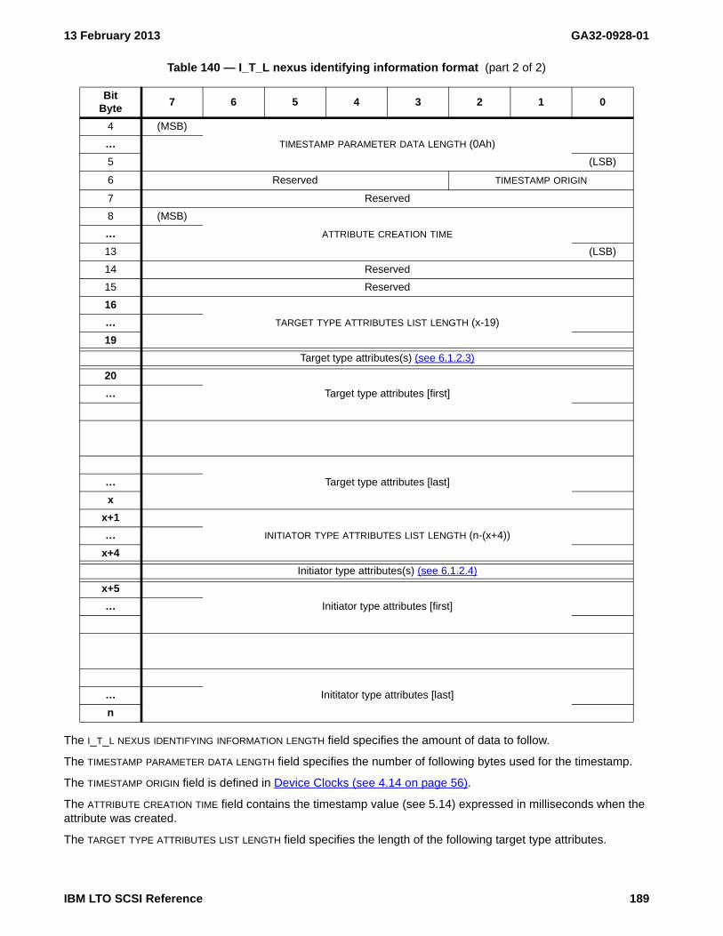
13 February 2013 GA32-0928-01
The I_T_L NEXUS IDENTIFYING INFORMATION LENGTH field specifies the amount of data to follow.
The TIMESTAMP PARAMETER DATA LENGTH field specifies the number of following bytes used for the timestamp.
The TIMESTAMP ORIGIN field is defined in Device Clocks (see 4.14 on page 56).
The ATTRIBUTE CREATION TIME field contains the timestamp value (see 5.14) expressed in milliseconds when the attribute was created.
The TARGET TYPE ATTRIBUTES LIST LENGTH field specifies the length of the following target type attributes.
4 (MSB)
TIMESTAMP PARAMETER DATA LENGTH (0Ah)…
5 (LSB)
6 Reserved TIMESTAMP ORIGIN
7 Reserved
8 (MSB)
ATTRIBUTE CREATION TIME…
13 (LSB)
14 Reserved
15 Reserved
16
TARGET TYPE ATTRIBUTES LIST LENGTH (x-19)…
19
Target type attributes(s) (see 6.1.2.3)
20
Target type attributes [first]…
Target type attributes [last]…
x
x+1
INITIATOR TYPE ATTRIBUTES LIST LENGTH (n-(x+4))…
x+4
Initiator type attributes(s) (see 6.1.2.4)
x+5
Initiator type attributes [first]…
Inititator type attributes [last]…
n
Table 140 — I_T_L nexus identifying information format (part 2 of 2)
BitByte
7 6 5 4 3 2 1 0
IBM LTO SCSI Reference 189

GA32-0928-01 13 February 2013
The target type attributes shall be listed in order by I_T NEXUS INDEX and ATTRIBUTE IDENTIFIER. The I_T NEXUS INDEX in this list is from the time the attribute was created and may be a different value than the I_T NEXUS INDEX associated with this I_T nexus at the time the READ DYNAMIC RUNTIME ATTRIBUTE is processed.
The INITIATOR TYPE ATTRIBUTES LIST LENGTH field specifies the length of the following initiator type attributes.
The initiator type attributes shall be listed in order by I_T NEXUS INDEX and ATTRIBUTE IDENTIFIER. The I_T NEXUS INDEX in this list is from the time the attribute was created and may be a different value than the I_T NEXUS INDEX associated with this I_T nexus at the time the READ DYNAMIC RUNTIME ATTRIBUTE is processed.
6.1.2.2.2 Number of I_T nexuses supported by dynamic runtime attributes: Indicates the maximum number of instances of target type attributes and initiator type attributes.
6.1.2.2.3 Timestamp when processed: Timestamp when the READ DYNAMIC RUNTIME ATTRIBUTE command that returns this attribute is processed. The DYNAMIC RUNTIME ATTRIBUTE VALUE field of the timestamp when processed attribute format is the value that would be returned by the REPORT TIMESTAMP parameter data format (see 6.28).
6.1.2.2.4 Reservation Information attribute: The DYNAMIC RUNTIME ATTRIBUTE VALUE field of the Reservation Information attribute is the list of I_T_L nexus identifying information for each I_T_L nexus that is a reservation holder. The DYNAMIC RUNTIME ATTRIBUTE VALUE field of the Reservation Information attribute is shown in table 141.
The RESERVATION TYPE field shall contain the reservation type as defined in table 142.
Table 141 — Reservation Information Dynamic Runtime Attribute value format
BitByte
7 6 5 4 3 2 1 0
0 RESERVATION TYPE
1 Reserved
I_T_L nexus identifying information descriptor(s) (see 6.1.2.2.1)
2
I_T_L nexus identifying information (see 6.1.2.2.1) (first)…
m
…
x
I_T_L nexus identifying information (see 6.1.2.2.1) (last)…
y
Table 142 — RESERVATION TYPE values (part 1 of 2)
Code Reservation Type
Persistent Reservations are in the range 00h - 0Fh
00h Persistent Reserve - Obsolete
01h Persistent Reserve - Write Exclusive
02h Persistent Reserve - Obsolete
03h Persistent Reserve - Exclusive Access
04h Persistent Reserve - Obsolete
05h Persistent Reserve - Write Exclusive – Registrants Only
06h Persistent Reserve - Exclusive Access – Registrants Only
07h Persistent Reserve - Write Exclusive – All Registrants
190 IBM LTO SCSI Reference

13 February 2013 GA32-0928-01
Each I_T_L nexus identifying information descriptor is a snapshot of the I_T_L nexus identifying information for an I_T_L nexus when a reservation is created by that I_T_L nexus or when that I_T_L nexus joins the reservation as a reservation holder. The Reservation Information attribute is created and an I_T_L nexus identifying information descriptor is created and added to the list when an I_T_L nexus reserves the logical unit with a PERSISTENT RESERVE OUT command or an SPC-2 RESERVE. Other I_T_L nexus identifying information descriptors are created for each I_T_L nexus that is a reservation holder, if any. This may be due to receipt of a PERSISTENT RESERVE OUT command or due to already registered I_T_L nexuses when an ALL REGISTRANTS type reseration is created. When an I_T_L nexus is no longer a reservation holder either due to the receipt of a PERSISTENT RESERVE OUT command to unregister the I_T_L nexus or the removal of the reservation holder as a side effect to some event that occurs (e.g., PREEMPT) the I_T_L nexus identifying information descriptor related to that I_T_L nexus shall be removed from the list. When the last I_T_L nexus identifying information descriptor has been removed and the reservation is removed the Reservation Information attribute shall be destroyed.
6.1.2.2.5 Registration Information attribute: The DYNAMIC RUNTIME ATTRIBUTE VALUE field of the Registration Information dynamic runtime attribute contains the list of I_T_L nexus identifying information descriptors for each I_T_L nexus that is registered for a persistent reservation. The DYNAMIC RUNTIME ATTRIBUTE VALUE field of the Registration Information dynamic runtime attribute is shown in table 143.
Each I_T_L nexus identifying information descriptor is created and added to the list when an I_T_L nexus registers with a PERSISTENT RESERVE OUT command. When an I_T_L nexus is no longer registered either due to a PERSISTENT RESERVE OUT command is recieved to unregister or the registration is removed as a side effect to some event that occurs the I_T_L nexus identifying information descriptor related to that I_T_L nexus shall be removed from the list. When the last I_T_L nexus identifying information descriptor has been removed the Registration Information attribute shall be destroyed.
6.1.2.2.6 Prevent Allow Medium Removal Information attribute: The DYNAMIC RUNTIME ATTRIBUTE VALUE field of the Prevent Allow Medium Removal Information attribute is the list of I_T_L nexus identifying information for each I_T_L nexus that has prevented media removal. The DYNAMIC RUNTIME ATTRIBUTE VALUE field of the Prevent
08h Persistent Reserve - Exclusive Access – All Registrants
09h - 0Fh Persistent Reserve - Reserved
10h SPC-2 Reserve
11h - FFh Reserved
Table 143 — Registration Information Dynamic Runtime Attribute value format
BitByte
7 6 5 4 3 2 1 0
0
I_T_L nexus identifying information (see 6.1.2.2.1) (first)…
m
…
x
I_T_L nexus identifying information (see 6.1.2.2.1) (last)…
y
Table 142 — RESERVATION TYPE values (part 2 of 2)
Code Reservation Type
IBM LTO SCSI Reference 191

GA32-0928-01 13 February 2013
Allow Medium Removal Information attribute is shown in table 144.
Each I_T_L nexus identifying information descriptor is created and added to the list when a volume’s removal is prevented due to a PREVENT ALLOW MEDIUM REMOVAL command received from that I_T_L nexus identifying information (i.e., the ATTRIBUTE CREATION TIME field is set to the time the PREVENT ALLOW REMOVAL command with the PREVENT bit set to one is received through that I_T_L nexus.) When an I_T_L nexus no longer prevents medium removal (e.g., a PREVENT ALLOW MEDIUM REMOVAL command with the PREVENT bit set to zero is received through that I_T_L nexus) the I_T_L nexus identifying information descriptor related to that I_T_L nexus shall be removed from the list. When the last I_T_L nexus identifying information descriptor has been removed from the list the Prevent Allow Medium Removal Information attribute shall be destroyed.
6.1.2.2.7 Last failed reservation attribute: Indicates the I_T_L nexus that last failed to get a reservation due to a reservation conflict. The DYNAMIC RUNTIME ATTRIBUTE VALUE field of the Last failed reservation attribute contains the I_T_L nexus identifying information (see 6.1.2.2.1) for the I_T_L nexus that last received a RESERVATION CONFLICT to one of the following commands:
a) PERSISTENT RESERVE OUT;b) PERSISTENT RESERVE IN;c) RESERVE (see SPC-2); andd) RELEASE (see SPC-2).
6.1.2.3 Target type attributes
Target type attributes (see table 145) shall be maintained and updated by the device server. All supported target type attributes shall have a status of read only (see 6.1)..
6.1.2.3.1 TransportID: Indicates the TransportID of the initiator port associated with this I_T_L nexus.
6.1.2.3.2 Target port ID: Indicates the relative target port identifier of the target port associated with this I_T_L nexus.
Table 144 — Prevent Allow Medium Removal Information Dynamic Runtime Attribute value format
BitByte
7 6 5 4 3 2 1 0
0
I_T_L nexus identifying information (see 6.1.2.2.1) (first)…
m
…
x
I_T_L nexus identifying information (see 6.1.2.2.1) (last)…
y
Table 145 — Target type attributes
Attribute Identifier
NameAttributeLength
(in bytes)Format Subclause
1000h TransportID 24 BINARY 6.1.2.3.1
1001h Target port ID (relative port identifier) 2 BINARY 6.1.2.3.2
1002h Last access time 12 BINARY 6.1.2.3.3
1003h to 13FFh Reserved
V - Variable
192 IBM LTO SCSI Reference

13 February 2013 GA32-0928-01
6.1.2.3.3 Last access time: Time of most recent command that effects the volume received through this I_T_L nexus.
The TIMESTAMP ORIGIN FIELD contains the origin of the timestamp used in the ACCESS TIME field.
The ACCESS TIME field contains the timestamp value when the most recent command was received through this I_T_L nexus that is not in the following list:
a) INQUIRY;b) LOG SENSE;c) MODE SENSE;d) READ DYNAMIC RUNTIME ATTRIBUTE;e) PERSISTENT RESERVE IN;f) REPORT LUNS;g) REQUEST SENSE; orh) TEST UNIT READY.
6.1.2.4 Initiator type attributes
Application clients may use the WRITE DYNAMIC RUNTIME ATTRIBUTE and READ DYNAMIC RUNTIME ATTRIBUTE commands to maintain initiator type attributes. All existent initiator type attributes shall follow the definition specified in table 147. All attributes, once created, shall exist until deleted by a WRITE DYNAMIC RUNTIME ATTRIBUTE command or until a power on event.
6.1.2.4.1 Device special file name: Indicates the device special file name used by the application client to identify the I_T_L nexus (e.g., “\\.\tape0”, “/dev/rmt0”, “/dev/sg0”).
Table 146 — Last access time format
BitByte
7 6 5 4 3 2 1 0
0 (MSB)TIMESTAMP PARAMETER DATA LENGTH (0Ah)
1 (LSB)
2 Reserved TIMESTAMP ORIGIN
3 Reserved
4 (MSB)
ACCESS TIME…
9 (LSB)
10 Reserved
11 Reserved
Table 147 — Initiator type attributes
Attribute Identifier NameAttributeLength
(in bytes)Format Subclause
1800h Device special file name (DSFN) 1..32 ASCII 6.1.2.4.1
1801h Data path failover enabled path 1..4 ASCII 6.1.2.4.2
1802h Host name (HN) 1..32 ASCII 6.1.2.4.3
1803h Operating system (OS) 1..16 ASCII 6.1.2.4.4
1804h Operating system version (OS_V) 1..32 ASCII 6.1.2.4.5
1805h Device driver name (DD_N) 1..16 ASCII 6.1.2.4.6
1806h Device driver version (DD_V) 1..16 ASCII 6.1.2.4.7
1807h Process ID 1..8 ASCII 6.1.2.4.8
1808h to 1BFFh Reserved
IBM LTO SCSI Reference 193
GA32-0928-01 13 February 2013
6.1.2.4.2 Data path failover enabled path: The path that is enabled for use in the device driver when data path failover (DPF) is enabled and is being used by the thread that issued this command.
6.1.2.4.3 Host name: Indicates the host name of the server that contains the initiator port of the I_T_L nexus (e.g., “foobar”).
6.1.2.4.4 Operating system: Indicates the operating system being used by the application client.
6.1.2.4.5 Operating system version: Indicates the version of the operating system specified in 6.1.2.4.4.
6.1.2.4.6 Device driver name: Indicates the name of the operating system device driver.
6.1.2.4.7 Device driver version: i)Indicates the version of the operating system device driver specified in 6.1.2.4.6.
6.1.2.4.8 Process ID: The process ID of the thread that is sending commands through this I_T nexus.
194 IBM LTO SCSI Reference

13 February 2013 GA32-0928-01
6.2 Diagnostic Parameters (Diag)
Diagnostic parameters are used with the SEND DIAGNOSTIC command(see SEND DIAGNOSTIC - 1Dh (see 5.2.32 on page 163) and RECEIVE DIAGNOSTIC RESULTS - 1Ch (see 5.2.20 on page 132) for additional information on the commands).
Terms used in this clause are:
Term DescriptionCD Cryptographic DiagnosticDiag DiagnosticPage Page CodeParm ParameterRcvDiag Receive Diagnostic ResultsSendDaig Send Diagnostic
6.2.1 Diag Page Formats
The drive supports two diagnostic pages for normal use: Page Code 00h and 80h. Page Code 81h is for engineering use only.
6.2.1.1 Page 00h
6.2.1.2 SendDiag Data - Page 00h
The format for the Send Diagnostic command follows:
Byte Description
0 Page Code: 00h1 Reserved (00h)2-3 Page Length: 0000h
6.2.1.3 RcvDiag Data - Page 00h
The format for the Receive Diagnostic Results command follows:
Byte Description
0 Page Code: 00h1 Reserved2-3 Page Length: 0002h4 Page Code Supported: 00h5 Page Code Supported: 80h
6.2.1.4 Page 80h
Page Code 80h is a general purpose page for sending flags and diagnostic parameters to the target.
6.2.1.4.1 SendDiag - Page 80h
The format for the Send Diagnostic command follows:
Byte Description
0 Page Code: 80h
IBM LTO SCSI Reference 195

GA32-0928-01 13 February 2013
1 Reserved2-3 Page Length (n-3)4-5 Diagnostic ID
This field specifies the diagnostic that is to be run6 Flags (Send Diagnostic command)
Bits Description7-1 Reserved0 Cartridge Required
Set to 1b when a cartridge is required for a diagnostic. When 1b, a cartridge must be loaded and ready for the Send Diagnostic command to be accepted. See specific diagnostic descriptions for cartridge use: some diagnostics require this bit to be set to 1b, some require it to be set to 0b, and some do not require a specific bit setting.• 0b: No cartridge required• 1b: Cartridge required
7 Reserved8-n Diagnostic Parameters
The Diagnostic Parameters field contains the parameters required to run the diagnostic.
See 6.2.2 for a list of supported diagnostic page 80h routines.
6.2.1.5 RcvDiag - Page 80h
The format for the Receive Diagnostic Results command follows:
Byte Description
0 Page Code: 80h1 Reserved2-3 Page Length (n-3)4-5 Diagnostic ID
This field contains the same value as that sent with the Send Diagnostic command for which thisresponse is associated.
6 FlagsSet to 00h for the Receive Diagnostic Results command
7 Reserved8-n Diagnostic Results
The Diagnostic Results field contains the results from the diagnostic.
See the individual Send Diagnostic parameter descriptions for the field contents. Refer to Supported Page 80h Diags (see 6.2.2) for a list of diagnostic parameters supported by the drive.
6.2.1.5.1 SIM/MIM Definition
SIMs (Service Information Messages), and MIMs (Medium Information Messages) provide the initiator and operator details on service problems encountered by the device. The first 9 bytes are common to both the SIMs and the MIMs.
196 IBM LTO SCSI Reference

13 February 2013 GA32-0928-01
6.2.1.5.1.1 SIM/MIM Header Data
Byte Description
0 Page CodeBit Description7-6 Reserved5-0 Page Code: 31h
1 Reserved2-3 Page Length: 0044h4-5 Parameter Code: 0000h6 Parameter control byte
Bit Description7 DU (Disable Update): 0b6 DS (Disable Save): 1b5 TSD (Target Save Disable): 1b4 ETC (Enable Threshold Comparison): 0b3-2 TMC (Threshold Met Comparison): 00b1 Reserved0 LP (List Parameter): 1b
7 Parameter length: 40h8 SIM/MIM Indicator
Value Description00h Bytes 9 through 71 are invalid.01h Bytes 9 through 71 are a SIM message. See “SIM Messages” on page 198.02h Bytes 9 through 71 are a MIM message. See “MIM Messages” on page 201.03-FF Bytes 9 through 71 are invalid.
Table 148 — SIM Data Structure
ByteBit
7 6 5 4 3 2 1 0
0 Page Code (31h)
1 Reserved
2 (MSB)PAGE LENGTH (0044h)
3 (LSB)
4 (MSB)PARAMETER CODE (0000h)
5 (LSB)
6 PARAMETER CONTROL (61h)
7 PARAMETER LENGTH (40h)
8 SIM/MIM INDICATOR
9SIM or MIM data
71
IBM LTO SCSI Reference 197

GA32-0928-01 13 February 2013
6.2.1.5.1.2 SIM Messages
The following data are the parameters for the hardware SIM message
Byte Description
9-15 Reserved16-19 PRODUCT REVISION LEVEL (microcode level): Same as bytes 32 - 35 in Standard Inquiry data
Table 149 — SIM Data Structure
ByteBit
7 6 5 4 3 2 1 0
9Reserved
15
16PRODUCT REVISION LEVEL
19
20 (MSB)SIM MESSAGE CODE
21 (LSB)
22Reserved
23
24 EXCEPTION MESSAGE CODE
25 SERVICE MESSAGE CODE
26 SERVICE MESSAGE SEVERITY CODE
27 Reserved
28 (MSB)EXCEPTION DATA
29 (LSB)
30 (MSB)SCD ERROR CODE
33 (LSB)
34 (MSB)FIRST FSC
37 (LSB)
38 (MSB)LAST FSC
41 (LSB)
42 (MSB)PRODUCT ID (8000h)
45 (LSB)
46Product Identifier
(MSB)VENDOR ID "IBM"
48 (LSB)
49 (MSB)PLANT OF MANUFACTURE
50 (LSB)
51 ’-’
52 (MSB)SERIAL NUMBER
63 (LSB)
64 (MSB)DEVICE TYPE
71 (LSB)
198 IBM LTO SCSI Reference

13 February 2013 GA32-0928-01
20-21 SIM MESSAGE CODE
Value Description(ASCII)‘00’ No Message‘41’ Device Degraded. Call for Service‘42; Device Hardware Failure. Call for Service‘43’ Service Circuits Failed, Operations Not Affected. Call for Service‘55’ Drive Needs Cleaning. Load Cleaning Cartridge‘57’ Drive Has Been CleanedAll Others Device Message message
22-23 Reserved24 EXCEPTION MESSAGE CODE
Value Description(ASCII)‘0’ Vendor-Reserved‘1’ Effect of Failure Is Unknown‘2’ Device Exception. No Performance Impact‘3; Exception on Host Interface xx See bytes 28-29 (Exception Data xx) in this SIM record for
the xx value.‘4’ Device Exception on ACF‘5’ Device Exception on Operator Panel‘6’ Device Exception on Tape Path‘7’ Device Exception in Drive‘8’ Cleaning Required‘9’ Cleaning Done‘A’-’F’ Vendor-Reserved
25 SERVICE MESSAGE CODE
Value Description(ASCII)‘0’ Vendor-Reserved‘1’ Repair Impact is Unknown‘2’-’6’ Vendor-Reserved‘7’ Repair Will Disable Access to Device serno (serno refers to serial number in bytes 52-63 of
this SIM record)‘9’ Clean Device‘A’ Device Cleaned‘B’ Device Cleaning For Performance Reasons is Required‘C’-’F’ Vendor-Reserved
26 SERVICE MESSAGE SEVERITY CODE
Value Description(ASCII)‘0’ SIM severity code “Service”‘1’ SIM severity code “Moderate”‘2’ SIM severity code “Serious”‘3’ SIM severity code “Acute”‘4’-’9’, ‘A’-’F’ Vendor-Reserved
27 Reserved28-29 EXCEPTION DATA
Interface Data is returned when byte 24 (Exception Message Code) in this SIM record contains theASCII value ‘3’.Value Description(ASCII)‘00’ interface 0 is indicated‘01’ interface 1 is indicated
30-33 SCD ERROR CODE: Error code indicated on SCD (ASCII code). For example 0x00000035 for SCD '5'.
IBM LTO SCSI Reference 199

GA32-0928-01 13 February 2013
34-37 FIRST FSC
38-41 LAST FSC
42-45 PRODUCT ID: ‘8000’ (these 4 bytes define “TAPE”)46-63 PRODUCT IDENTIFIER
Broken out into constituent bytes:Byte Description46-48 MANUFACTURER: “IBM”49-50 PLANT OF MANUFACTURE
51 ‘-’ (Dash symbol)52-63 SERIAL NUMBER
64-71 DEVICE TYPE (device type portion of PRODUCT IDENTIFICATION; Inquiry Standard Data bytes 16-23)
200 IBM LTO SCSI Reference

13 February 2013 GA32-0928-01
6.2.1.5.2 MIM Messages
Media Information Messages (MIMs) are supported by this device. The following data are the parameters for the MIM
Byte Description
9-15 Vendor-Reserved16-19 PRODUCT REVISION LEVEL (microcode level): Same as bytes 32 - 35 in Standard Inquiry data
Table 150 — MIM Data Structure
ByteBit
7 6 5 4 3 2 1 0
9Reserved
15
16PRODUCT REVISION LEVEL
19
20 (MSB)MIM MESSAGE CODE
21 (LSB)
22Reserved
23
24 EXCEPTION MESSAGE CODE
25 MEDIA MESSAGE CODE
26 MEDIA MESSAGE SEVERITY CODE
27Reserved
29
30 (MSB)FAULT SYMPTOM CODE (FSC)
33 (LSB)
34VOLID (Volume Serial Number)
39
38 VOLID VALID
41 Reserved
42 (MSB)PRODUCT ID (8000h)
45 (LSB)
46Product Identifier
(MSB)VENDOR ID "IBM"
48 (LSB)
49 (MSB)PLANT OF MANUFACTURE
50 (LSB)
51 ’-’
52 (MSB)SERIAL NUMBER
63 (LSB)
64 (MSB)DEVICE TYPE
71 (LSB)
IBM LTO SCSI Reference 201

GA32-0928-01 13 February 2013
20-21 MIM MESSAGE CODE
Value Description(ASCII)‘00’ No Message‘60’ Bad Media, Read Only permitted‘61’ Rewrite Media if possible‘62’ Tape Directory Invalid. Re-read media if possible‘64’ Bad Media-Cannot Read or Write‘72’ Replace Cleaner CartridgeOthers Vendor-Reserved
22-23 Reserved24 EXCEPTION MESSAGE CODE
Value Description(ASCII)‘2’ Data Degraded‘4’ Medium Degraded‘6’ CM Error‘7’ Medium ExceptionOthers Vendor-Reserved
25 MEDIA MESSAGE CODE
26 MEDIA MESSAGE SEVERITY CODE
Value Description(ASCII)‘0’ Service‘1’ Moderate-High Temp Read/Write Errors Detected‘2’ Serious-Permanent Read/Write Errors Detected‘3’ CM ErrorOthers Vendor-Reserved
27-29 Reserved30-33 FAULT SYMPTOM CODE (FSC)34-39 VOLID (Volume Serial Number) (in ASCII). Only valid if indicated by VOLID Valid Flag (byte 40)40 VOLID VALID
Value Description(ASCII)‘0’ VOLID (bytes 34-39) not valid‘1’ VOLID valid, obtained from tape‘3’ VOLID valid, obtained from host (MAM Attribute ID 0806 in CM)‘5’ VOLID valid, obtained from library (volser in mechanism related page in CM)Others Vendor-Reserved for future use (odd number will always indicate VOLID valid)
41 Reserved42-45 PRODUCT ID: ‘8000’ (these 4 bytes define “TAPE”)46-63 PRODUCT IDENTIFIER
Broken out into constituent bytes:Byte Description46-48 MANUFACTURER: “IBM”49-50 PLANT OF MANUFACTURE
51 ‘-’ (Dash symbol)52-63 SERIAL NUMBER
64-71 DEVICE TYPE (device type portion of PRODUCT IDENTIFICATION; Inquiry Standard Data bytes 16-23)
202 IBM LTO SCSI Reference

13 February 2013 GA32-0928-01
6.2.2 Supported Page 80h Diags
Table 151 shows the supported diagnostic page 80h routines and indicates values required in the Send Diagnostic CDB. These diagnostics reside in the device (see SEND DIAGNOSTIC - 1Dh (see 5.2.32 on page 163) and RECEIVE DIAGNOSTIC RESULTS - 1Ch (see 5.2.20 on page 132) for additional information on the commands). Individual diagnostic descriptions follow table 151.
Table 151 — Supported Page 80 Diag Routines
ID Name/DescriptionSee
PageParm
LengthResult
Length bSelfTest
DevOfl
UnitOfl
CartReq'd
None Self Test 204 0000h - 1 X X -
0090h Primary Port Wrap Test 205 0008h 0051h 0 X X X
0100h POST A Self Test Diagnostic 206 0008h 0051h 0 X X X
0101h POST B Performance Diagnostic a 208 0008h 0051h 0 X 1 1
0102h POST C Media Test Diagnostic 210 0008h 0051h 0 X 1 1
0103h POST D Head Test Diagnostic 211 0008h 0051h 0 X 1 1
0110h Extended Write/Read Test 212 0020h 000Bh 0 X X 1
0160h Force Dump 218 0008h - 0 X X X
0161h Write Dump to Cartridge a 219 0008h 0051h 0 X 1 1
0162h Write Dump to FLASH (EEPROM) - 0008h - 0 X X X
016Fh Clear FLASH Dump (EEPROM) - 0008h - 0 X X X
0170h Create FMR Cartridge a 221 0008h 0051h 0 X 1 1
0171h Unmake FMR Cartridge a 223 0008h 0051h 0 X 1 0
0175h Use FMR Cartridge 225 0008h 0051h 0 X 1 0
0190h Set Traps 227 000Ah - 0 X X X
0191h Remove Traps 228 000Ah - 0 X X X
0210h Terminate Immediate Command 230 000Ah - 0 X X 1
1002h Read Thermal Sensor - 0008h 0051h 0 X X X
2002h Reset Drive (Soft) 234 0008h - 0 1 X 0
E000h Encryption Diagnostics 235 ???? ???? 0 X X X
Legend- Not Applicable???? Variable
a These diagnostics will destroy all data on the currently mounted cartridge.b GOOD status is returned for diagnostics which expect result data based solely on validation of the diagnostic. The
Receive Diagnostics Results command must be used to determine the success or failure of the actual execution of such diagnostics. Diagnostic procedures are recommended above.
IBM LTO SCSI Reference 203

GA32-0928-01 13 February 2013
6.2.3 Diag - SelfTest: Self Test
When the SelfTest bit is 1b in the Send Diagnostic command (see SEND DIAGNOSTIC - 1Dh (see 5.2.32 on page 163) and RECEIVE DIAGNOSTIC RESULTS - 1Ch (see 5.2.20 on page 132) for additional information on the commands), the target runs the normal power-on self test (POST A) diagnostics that occur at bring-up. No diagnostic results are returned.
6.2.3.1 SendDiag Command - Self Test
Table 152 shows the Send Diagnostic command format to specify Self Test (the SelfTest bit is set to 1b).
When the SelfTest bit is 1b in the Send Diagnostic command, the target will process its default power-on self test. If the self test successfully passes, the command is terminated with Good status. If the self test detects a failure, the command is terminated with CHECK CONDITION status and the sense key is set to Hardware Error.
6.2.3.2 RcvDiag Data - Self Test
There are no diagnostic results for the self test.
Table 152 — SendDiag CDB - Self Test
ByteBit
7 msb 6 5 4 3 2 1 0 lsb
0 Operation code (1Dh)
1 Obsolete (LUN) PF (1b)Reserved
(0b)SelfTest
(1b)DevOfl (0b) UnitOfl (0b)
2 Reserved (00h)
3 (MSB)Parameter List Length (0000h)
4 (LSB)
5 Control Byte (see 5.1.2.3)
204 IBM LTO SCSI Reference

13 February 2013 GA32-0928-01
6.2.4 Diag - 0090h: Primary port wrap test
This test will perform a wrap test on the specified primary port. A wrap tool must be attached prior to running this command. See SEND DIAGNOSTIC - 1Dh (see 5.2.32 on page 163) and RECEIVE DIAGNOSTIC RESULTS - 1Ch (see 5.2.20 on page 132) for additional information on the commands.
6.2.4.1 SendDiag Parm Data - Primary port wrap test
Table 153 shows the parameter data for the Send Diagnostic command.
The following parameters apply:
• CR (cartridge required): 0b
• PORT IDENTIFIER: This field is identical to the PORT IDENTIFIER field described in IP 83h: Device Identification (see 6.3.4 on page 246). If the value of the PORT IDENTIFIER is zero, then the wrap test will be performed on all primary ports. If the value is a valid port identifier, the wrap test is performed on the port indicated by the PORT IDENTIFIER field. If an invalid port identifier value is used, the drive will respond with a CHECK CONDITION for INVALID FIELD IN PARAMETER LIST.
6.2.4.2 RcvDiag Data - Primary port wrap test
Table 154 shows the diagnostic results data received from the attempted Primary port wrap test diagnostic.
Table 153 — Primary Port Wrap Test SendDiag Parm Data
Byte 7 6 5 4 3 2 1 0
0 PAGE CODE (80h)
1 Reserved
2 (MSB)PAGE LENGTH (0004h)
3 (LSB)
4DIAGNOSTIC ID (0090h)
5
6 FLAGS (0000000b) CR (0b)
7 PORT IDENTIFIER
Table 154 — Primary Port Wrap Test Receive Diag Parm Data
Byte 7 6 5 4 3 2 1 0
0 PAGE CODE (80h)
1 Reserved
2 (MSB)PAGE LENGTH (004Dh)
3 (LSB)
4DIAGNOSTIC ID (0090h)
5
6 FLAGS
7 Reserved
8 FLAGS (00000b) BLOCKEDSIM/MIM
PRESENTERROR
9SIM/MIM Message or All Zeros
80
IBM LTO SCSI Reference 205

GA32-0928-01 13 February 2013
6.2.5 Diag - 0100h: POST A
This diagnostic runs the POST A (power-on self test) diagnostics, as does running the Self Test diagnostic by setting the SelfTest bit to 1b in a Send Diagnostic command. However, unlike Self Test, the POST A diagnostic returns data through the Receive Diagnostic Results command. (see SEND DIAGNOSTIC - 1Dh (see 5.2.32 on page 163) and RECEIVE DIAGNOSTIC RESULTS - 1Ch (see 5.2.20 on page 132) for additional information on the commands)
6.2.5.1 SendDiag Parm Data - POST A
Table 155 shows the parameter data for the Send Diagnostic command.
Table 155 — SendDiag Parm Data - POST A
ByteBit
7 msb 6 5 4 3 2 1 0 lsb
0 Page Code (80h)
1 Reserved (00h)
2 (MSB)Page Length (0004h)
3 (LSB)
4 (MSB)Diagnostic ID (0100h)
5 (LSB)
6 Flags (0000000b) CR(x)
7 Reserved (00h)
Note 1 - The CR (Cartridge Required) flag may be set to 0b or 1b. If a cartridge is in the drive when this diagnostic is received, some diagnostics will not run. If the diagnostic is blocked because a cartridge is loaded in the drive or for any other reason, the BLOCKED bit is set in the Receive Diagnostics Results data.
206 IBM LTO SCSI Reference

13 February 2013 GA32-0928-01
6.2.5.2 RcvDiag Data - POST A
Table 156 shows the diagnostic results data received from the POST A diagnostic.
Table 156 — RcvDiag Data - POST A
ByteBit
7 msb 6 5 4 3 2 1 0 lsb
0 Page Code (80h)
1 Reserved (00h)
2 (MSB)Page Length (004Dh)
3 (LSB)
4 (MSB)Diagnostic ID (0100h)
5 (LSB)
6 Flags (00h)
7 Reserved (00h)
8 Reserved (00000b)Diagnostic
BlockedSIM/MIM Present
Error
9SIM/MIM message or all zeros
80
Note 1 - The ERROR bit in byte 8 is set when the diagnostic detects an error.Note 2 - The SIM/MIM Present bit in byte 8 is set when a SIM or MIM message is contained in the diagnostic
results.Note 3 - SIM/MIM messages are defined exactly as described in SIM/MIM Definition (see 6.2.1.5.1 on page 196);
the SIM/MIM is not valid if the SIM/MIM Present bit is 0b.Note 4 - The Diagnostic Blocked bit is set when the diagnostic cannot run all its tests. This occurs if a cartridge is in
the drive.
IBM LTO SCSI Reference 207

GA32-0928-01 13 February 2013
6.2.6 Diag - 0101h: POST B Performance
The Performance Diagnostic performs a test to determine how well the tape drive writes data. If the percentage degradation exceeds the threshold, the SEND DIAGNOSTIC command will return a CHECK CONDITION. The SENSE KEY will be set to 1h and the ASC/ASCQ set to 0000h. The FSC field of sense data will be set to 52E5h, if the degradation is in the forward direction, or 52E6h, if the degradation was in the backward direction. The FSC FLAG field of the sense data will be set to the percentage. TapeAlert2 (Write Warning) will be set and the SCD will display the character 'A.' The RECEIVE DIAGNOSTIC command will return SIM data related to the failure.
See SEND DIAGNOSTIC - 1Dh (see 5.2.32 on page 163) and RECEIVE DIAGNOSTIC RESULTS - 1Ch (see 5.2.20 on page 132) for additional information on the commands.
6.2.6.1 SendDiag Parm Data - POST B Performance
Table 157 shows the parameter data for the Send Diagnostic command.
Table 157 — SendDiag Parm Data - POST B
ByteBit
7 msb 6 5 4 3 2 1 0 lsb
0 Page Code (80h)
1 Reserved (00h)
2 (MSB)Page Length (0004h)
3 (LSB)
4 (MSB)Diagnostic ID (0101h)
5 (LSB)
6 Flags (0000000b)Cartridge Required
(1b)
7 Reserved (00h)
Note 1 - Cartridge Required=1b, a cartridge must be loaded and ready.
208 IBM LTO SCSI Reference

13 February 2013 GA32-0928-01
6.2.6.2 RcvDiag Data - POST B Performance
Table 158 shows the diagnostic results data received from the POST B diagnostic.
Table 158 — RcvDiag Data - POST B
ByteBit
7 msb 6 5 4 3 2 1 0 lsb
0 Page Code (80h)
1 Reserved (00h)
2 (MSB)Page Length (004Dh)
3 (LSB)
4 (MSB)Diagnostic ID (0101h)
5 (LSB)
6 Flags (00h)
7 Reserved (00h)
8 Reserved (00000b)Diagnostic
BlockedSIM/MIM Present
Error
9SIM/MIM message or all zeros
80
Note 1 - The Error bit in byte 8 is set when the diagnostic detects an error.Note 2 - The SIM/MIM Present bit in byte 8 is set when a SIM or MIM message is contained in the diagnostic
results.Note 3 - SIM/MIM messages are defined exactly as described in SIM/MIM Definition (see 6.2.1.5.1 on page 196);
the SIM/MIM is not valid if the SIM/MIM Present bit is 0.
IBM LTO SCSI Reference 209

GA32-0928-01 13 February 2013
6.2.7 Diag - 0102h: POST C Media Test
6.2.7.1 SendDiag Parm Data - POST C Media Test
6.2.7.2 RcvDiag Data - POST C Media Test
Table 159 — SendDiag Parm Data - POST C Media Test
ByteBit
7 6 5 4 3 2 1 0
0 Page Code (80h)
1 Reserved
2 (MSB)Page Length (0004h)
3
4 (MSB)Diagnostic ID (0102h)
5
6 Flags (0000000b)
7 Reserved
Table 160 — Table 325. POST C Media Test Receive Diag Parm Data
ByteBit
7 6 5 4 3 2 1 0
0 Page Code (80h)
1 Reserved
2 (MSB)Page Length (004Dh)
3 (LSB)
4 (MSB)Diagnostic ID (0102h)
5 (LSB)
6 Flags
7 Reserved
8 Flags (00000b)Diag.
BlockedSIM/MIM Present
ERROR
9SIM/MIM message or all zeros
80
210 IBM LTO SCSI Reference

13 February 2013 GA32-0928-01
6.2.8 Diag - 0103h: POST D Head Test
6.2.8.1 SendDiag Parm Data - POST D Head Test
6.2.8.2 RcvDiag Data - POST D Head Test
Table 161 — SendDiag Parm Data - POST D Head Test
ByteBit
7 6 5 4 3 2 1 0
0 Page Code (80h)
1 Reserved
2 (MSB)Page Length (0004h)
3 (LSB)
4 (MSB)Diagnostic ID (0103h)
5 (LSB)
6 Flags (0000000b)
7 Reserved
Table 162 — Receive Diag Parm Data - POST D Head Test
ByteBit
7 6 5 4 3 2 1
0 Page Code (80h)
1 Reserved
2 (MSB)Page Length (004Dh)
3 (LSB)
4 (MSB)Diagnostic ID (0103h)
5 (LSB)
6 Flags
7 Reserved
8 Flags (00000b)Diag.
BlockedSIM/MIM Present
ERROR
9SIM/MIM message or all zeros
80
IBM LTO SCSI Reference 211

GA32-0928-01 13 February 2013
6.2.9 Diag - 0110h: Extended Write / Read Test
The Extended Write / Read Test diagnostic causes the drive to process an extended write/read test. A large set of parameters are provided to allow the controlling program flexibility in specifying the test sequence.
The Extended Write / Read Test diagnostic may be run in ‘Immediate mode’. When this mode is selected, ending status is presented after initial parameter checking is complete. Command progress or completion is determined by checking for sk/asc/ascq = 0/0016 (NO SENSE / OPERATION IN PROGRESS) with a REQUEST SENSE command. In addition, when the diagnostic is run in Immed mode, the command may be terminated by using the SEND DIAGNOSTIC Command - Terminate Immed Command option (see 6.2.17).
A cartridge must be loaded and ready prior to running this diagnostic.
The design of the Extended Write / Read Test diagnostic is such that any temp or perm errors that occur while it is running may be retrieved through normal Deferred Check Condition reporting. If the diagnostic is run in non-Immed mode, then those errors may be retrieved following completion. If the diagnostic is run in Immed mode, the errors may be retrieved while it is still running, through use of a Request Sense / TUR command loop. In either mode, the Diagnostic Termination code in the Receive Diagnostic Results data should be checked at completion. Extended Write/Read Test diagnostic (see 4.19.1 on page 66) provides an example sequence an application client could use.
212 IBM LTO SCSI Reference

13 February 2013 GA32-0928-01
6.2.9.1 Send Data – Extended Write / Read Test
Table 163 shows the Send Diagnostic parameter data for the Extended Write / Read Test diagnostic.
The following parameters apply:
Byte Description
0 PAGE CODE - Selects the diagnostic page as 80h which is the IBM general purpose page.1 Reserved2-3 PAGE LENGTH - The length in bytes of the diagnostic parameters that follow this field.4-5 DIAGNOSTIC ID - The ID of the specific general purpose diagnostic.6 FLAGS - Flags specific to this diagnostic.
Bit Description7-1 Reserved0 CR - Cartridge Required (1b)
Value Description0b A cartridge is not required to be loaded and ready.1b A cartridge must be loaded and ready.
Table 163 — Send Data – (Diag 0110h) Extended Write / Read Test
ByteBit
7 msb 6 5 4 3 2 1 0 lsb
0 PAGE CODE (80h)
1 Reserved (00h)
2 (MSB)PAGE LENGTH (001ch)
3 (LSB)
4 (MSB)DIAGNOSTIC ID (0110h)
5 (LSB)
6 FLAGS (0000000b) CR(1b)
7 TSTLC TSTLF UNCTL TESCTL Reserved (000b) IMMED
8 WRTTST RDTST Reserved (0000b) STCTL ENDCTL
9 CHGPAT SDCTL Reserved (00b) DATAPAT
10 WSCTL RSCTL ERPCTL ROLLCTL Rsvd (00b) CALCTL
11 WRITE SPEED READ SPEED
12 TEMP ERR STOP COUNT
13 Reserved (00h)
14 (MSB)TEST LOOP COUNT
15 (LSB)
16 (MSB)STARTING LB NUMBER
19 (LSB)
20 (MSB)LOGICAL BLOCK SIZE
23 (LSB)
24 (MSB)LOGICAL BLOCK COUNT
27 (LSB)
28 (MSB)STARTING SEED
31 (LSB)
IBM LTO SCSI Reference 213

GA32-0928-01 13 February 2013
7 Test Loop / Immed Mode OptionsBit Description7 TSTLC - test loop count flag
Value Description0b The test will be run one time.1b The entire test will be repeated as specified in the TEST LOOP COUNT field (i.e.,
bytes 14-15).6 TSTLF - test loop forever flag
Value Description0b The entire test will not be looped forever.1b The entire test will continually loop forever if the IMMED bit is set to one.
If the TSTLF flag and the IMMED bit are both set to one, then the TSTLC flag and the TEST LOOP COUNT field (i.e., bytes 14-15), are ignored. This flag is ignored if the IMMED bit is set to zero.
5 UNCTL - unload control flagValue Description0b The tape will not be unloaded following write or read tests.1b The tape will be unloaded following the completion of each write or read test. If
the entire test is not yet complete, the tape will be reloaded prior to starting the next portion of the test.
4 TESCTL - temp error stop control flagValue Description0b The test will not terminate based on a temp error count.1b The test will terminate when the number of temp errors exceeds the value in the
TEMP ERR STOP COUNT field (i.e., byte 12).3-1 Reserved (ignored)0 IMMED – immediate status bit
Value Description0b Present status when the command is completed.1b Present status when parameter checking is completed and the command is
started.8 Write/Read Options
Bit Description7 WRTTST - perform write test
Value Description0b No write test will be performed.1b A write test will be performed as specified in the remaining parameters.
6 RDTST - perform read testValue Description0b No read test will be performed.1b A read test will be performed as specified in the remaining parameters.
5-2 Reserved (ignored)1 STCTL - start control flag
Value Description0b All write and read tests will start at LB 0.1b All write and read tests will start at the LB Number specified in the STARTING LB
NUMBER field (i.e., bytes 16-19).0 ENDCTL - end control flag
Value Description0b All write and read tests will continue until LEOT.1b All write and read tests will continue as specified in the LOGICAL BLOCK SIZE field
(i.e., bytes 20-23) and the LOGICAL BLOCK COUNT field (i.e., bytes 24-27).
214 IBM LTO SCSI Reference

13 February 2013 GA32-0928-01
9 Data Pattern Options: These fields specify what type of data pattern will be loaded into the data bufferprior to starting a write test.Bit Description7 CHGPAT - change pattern flag
Value Description0b The data pattern will not change if the write test is looped.1b For each loop of a write test, the data pattern will cycle through the data pattern
types listed in the DATAPAT field (i.e., bits 3-0) starting with its current value.6 SDCTL - seed control flag
Value Description0b No starting seed is specified.1b The starting seed for Random, Incrementing, and Repeating data patterns is
specified in the STARTING SEED field (i.e., bytes 28-31).5-4 Reserved (ignored)3-0 DATAPAT - data pattern type
Table 164 — DATAPAT description
Value Pattern Type Description
0h Random
If SDCTL = 0b, then a predefined pseudo-random pattern is usedIf SDCTL = 1b, then each word of the predefined pseudo-random pattern is modified by the value in the STARTING SEED field (i.e., bytes 28-31) per the following psuedocode: pseudo-random pattern: pattern[] = {random_word_1, random_word_2, random_word_3, ...};word[TEST LOOP COUNT];seed = STARTING SEED;for (index=0; index++;TEST_LOOP_COUNT)word[index] = pattern[index] | seed++;
1h Incrementing
If SDCTL = 0b, then the pattern increments starting at 0000 0000h (i.e., 0000 0000h, 0000 0001h, 0000 0002h, etc.)If SDCTL = 1b, then the pattern increments starting from the value in the STARTING SEED field
2h RepeatingIf SDCTL = 0b, then the pattern used is all 0's (00000000h repeated)If SDCTL = 1b, then the pattern used is the value in the STARTING SEED field repeated
3h All zeros 0000 0000h repeated
4h All ones FFFF FFFFh repeated
5h Alt A 0FF0 F00Fh repeated
6h Alt B A55A 5AA5h repeated
7h-Fh Reserved Ignored (Random pattern is used)
IBM LTO SCSI Reference 215

GA32-0928-01 13 February 2013
10 Speed / ERP / Cal OptionsBit Description7 WSCTL - write speed control flag
Value Description0b Writing speed will be controlled by the default drive methods.1b Writing speed will be fixed to the value set in the WRITE SPEED field (see byte 11).
6 RSCTL - read speed control flagValue Description0b Reading speed will be controlled by the default drive methods.1b Reading speed will be fixed to the value set in the READ SPEED field (see byte 11).
5 ERPCTL – write/read ERP control flagValue Description0b Regular write/read ERPs will be controlled by default drive methods.1b Regular write/read ERPs will be limited (equivalent to setting Mode Page 01h
Write Retry Limit and Read Retry Limit both to 05h).4 ROLLCTL - rolling cal control flag
Value Description0b Rolling cal (sticky / intervention ERPs) will be controlled by default drive methods.1b Rolling cal ERPs will be disabled
3-2 Reserved (ignored)1-0 CALCTL - channel calibration control
Value Description00b Channel calibrations will be controlled by default drive methods.01b Normal channel calibration will be disabled.10b An IFC channel calibration will be performed prior to starting each write pass11b An IFC channel calibration will be performed prior to starting the first write pass
only11 Write/read Fixed Speed Setting
Bit Description7-4 WRITE SPEED: When the WSCTL flag is set to one, this field specifies the fixed speed setting to be
used while writing.3-0 READ SPEED: When the RSCTL flag is set to one, this field specifies the fixed speed setting to be
used while reading.12 TEMP ERR STOP COUNT: When the TESCTL flag is set to one, this field specifies the count of temp errors,
which when exceeded, will cause the test to terminate.14-15 TEST LOOP COUNT: When the TSTLC flag is set to one, this count specifies the number of times the entire
test is repeated.16-19 STARTING LB NUMBER: When the STCTL flag is set to one, this field specifies the LB Number to be used for
the start of all write and read tests.20-23 LOGICAL BLOCK SIZE: This field specifies the logical block size (in bytes) of each block to be written or
read. The value of LOGICAL BLOCK SIZE is limited to the same values supported by the device forhost write and read commands (i.e., the value reported in the READ BLOCK LIMITS command).
24-27 LOGICAL BLOCK COUNT: When the ENDCTL flag is set to one, this count specifies the number of logicalblocks that will be processed during each write or read test.
28-31 STARTING SEED: When the SDCTL flag is set to one, this field specifies the pattern starting seed value.
216 IBM LTO SCSI Reference

13 February 2013 GA32-0928-01
6.2.9.2 Results Data – Extended Write / Read Test
Table 2 shows the Receive Diagnostic Results data received from the Extended Write / Read Test diagnostic.
The following parameters apply:
Byte Description
0 PAGE CODE - Identifies the diagnostic page as 80h which is the IBM general purpose page.1 Reserved2-3 PAGE LENGTH - The length in bytes of the diagnostic parameters that follow this field.4-5 DIAGNOSTIC ID - The ID of the specific general purpose diagnostic.6 FLAGS - Flags specific to this diagnostic.7 Reserved8 DIAGNOSTIC TERMINATION CODE
Value Description00h Diagnostic completed all tests.01h Diagnostic was terminated by a perm error condition.02h Diagnostic was terminated due to the Temp Err Stop Count.03h Diagnostic was terminated by the Send Diagnostic – Terminate Immed Command routine.04h Diagnostic was terminated due to a 'blocked' starting condition. This would typically be an indi-
cation of a firmware problem, or a write protected volume.9-10 TOTAL TEMP ERROR COUNT: The total number of temp write/read errors that occurred while running the
diagnostic. This count will freeze at a maximum value of FFFFh.
Table 165 — Results Data – (Diag 0110h) Extended Write / Read Test
ByteBit
7 msb 6 5 4 3 2 1 0 lsb
0 PAGE CODE (80h)
1 Reserved (00h)
2 (MSB)PAGE LENGTH (0007h)
3 (LSB)
4 (MSB)DIAGNOSTIC ID (0110h)
5 (LSB)
6 FLAGS (00h)
7 Reserved (00h)
8 DIAGNOSTIC TERMINATION CODE
9 (MSB)TOTAL TEMP ERROR COUNT
10 (LSB)
IBM LTO SCSI Reference 217

GA32-0928-01 13 February 2013
6.2.10 Diag - 0160h: Force Dump
This diagnostic forces a dump. The dump data is stored in device control storage and can be read by the READ BUFFER command (Buffer ID of 00h) (see 5.2.17).
When a higher priority dump has been generated automatically by the drive but has not yet been read, the drive will ignore this Send Diagnostic command and return GOOD status.
Because forcing a drive dump will overwrite any previously stored dump, before forcing the dump the DUMP field of the sense data should be examined to determine if a drive dump exists.
See SEND DIAGNOSTIC - 1Dh (see 5.2.32 on page 163) and RECEIVE DIAGNOSTIC RESULTS - 1Ch (see 5.2.20 on page 132) for additional information on the commands.
6.2.10.1 SendDiag Parm Data - Force Dump
Table 166 shows the parameter data for the Send Diagnostic command.
6.2.10.2 RcvDiag Data - Force Dump
There are no diagnostic results for this function.
Table 166 — SendDiag Parm Data - Force Dump
ByteBit
7 msb 6 5 4 3 2 1 0 lsb
0 Page Code (80h)
1 Reserved (00h)
2 (MSB)Page Length (0004h)
3 (LSB)
4 (MSB)Diagnostic ID (0160h)
5 (LSB)
6 Flags (0000000b)Cartridge Required
(x)
7 Reserved (00h)
Note 1 - The Cartridge Required flag may be set to 0b or 1b.
218 IBM LTO SCSI Reference

13 February 2013 GA32-0928-01
6.2.11 Diag -0161h: Write Dump to Cartridge
This diagnostic causes dump information residing in the device control storage to be written to a cartridge without the need to retrieve the dump data across the host interface. A cartridge is required to be loaded to run the diagnostic (see SEND DIAGNOSTIC - 1Dh (see 5.2.32 on page 163) and RECEIVE DIAGNOSTIC RESULTS - 1Ch (see 5.2.20 on page 132) for additional information on the commands).
6.2.11.1 SendDiag Parm Data - Write Dump to Cartridge
Table 167 shows the parameter data for the Send Diagnostic command.
Table 167 — SendDiag Parm Data - Write Dump to Cartridge
ByteBit
7 msb 6 5 4 3 2 1 0 lsb
0 Page Code (80h)
1 Reserved (00h)
2 (MSB)Page Length (0004h)
3 (LSB)
4 (MSB)Diagnostic ID (0161h)
5 (LSB)
6 Flags (0000000b)Cartridge Required
(1b)
7 Reserved (00h)
Note 1 - Cartridge Required=1b, a cartridge must be loaded and ready.
IBM LTO SCSI Reference 219
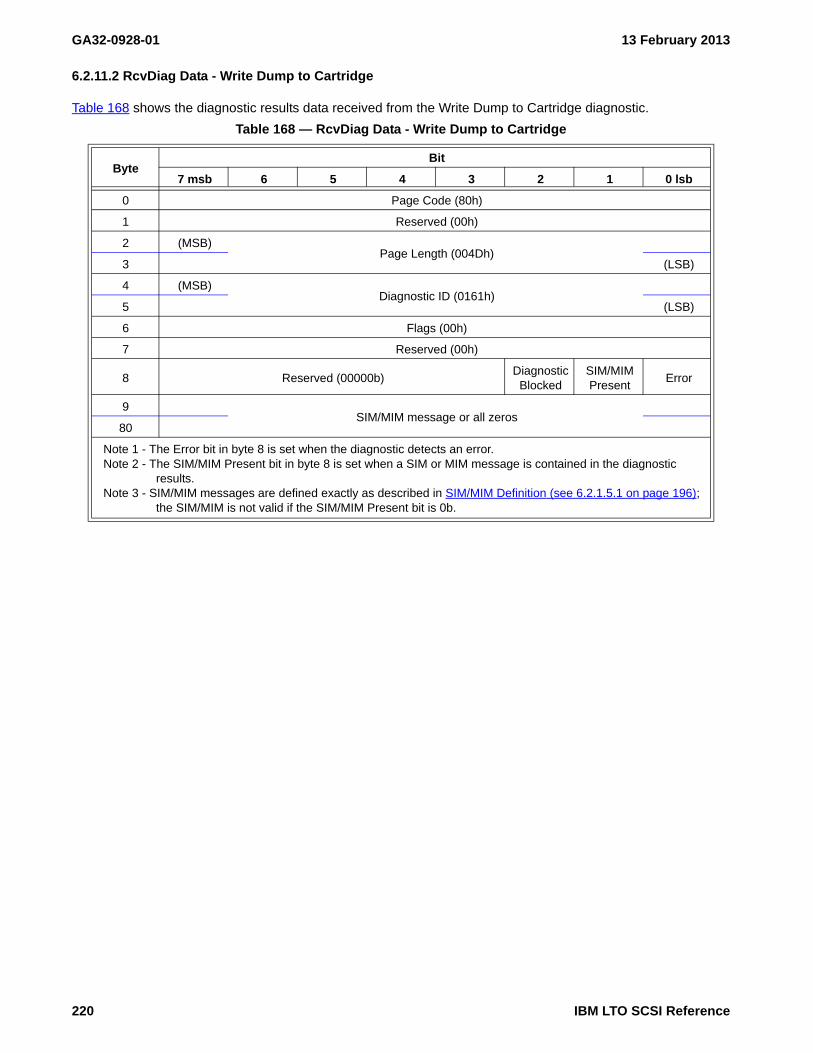
GA32-0928-01 13 February 2013
6.2.11.2 RcvDiag Data - Write Dump to Cartridge
Table 168 shows the diagnostic results data received from the Write Dump to Cartridge diagnostic.
Table 168 — RcvDiag Data - Write Dump to Cartridge
ByteBit
7 msb 6 5 4 3 2 1 0 lsb
0 Page Code (80h)
1 Reserved (00h)
2 (MSB)Page Length (004Dh)
3 (LSB)
4 (MSB)Diagnostic ID (0161h)
5 (LSB)
6 Flags (00h)
7 Reserved (00h)
8 Reserved (00000b)Diagnostic
BlockedSIM/MIM Present
Error
9SIM/MIM message or all zeros
80
Note 1 - The Error bit in byte 8 is set when the diagnostic detects an error.Note 2 - The SIM/MIM Present bit in byte 8 is set when a SIM or MIM message is contained in the diagnostic
results. Note 3 - SIM/MIM messages are defined exactly as described in SIM/MIM Definition (see 6.2.1.5.1 on page 196);
the SIM/MIM is not valid if the SIM/MIM Present bit is 0b.
220 IBM LTO SCSI Reference

13 February 2013 GA32-0928-01
6.2.12 Diag - 0170h: Create FMR Cartridge (not on LTO5)
See “Send Diagnostic - 1Dh” on page 167 and “Receive Diagnostic Results - 1Ch” on page 139 for additional information on the commands. This diagnostic causes the device microcode to be written to a cartridge, creating a field microcode replacement (FMR) cartridge. A cartridge is required to be mounted and ready in preparation for this diagnostic. All data on the cartridge prior to running this diagnostic is lost.
After a successful completion of this diagnostic, the cartridge is an FMR cartridge that may be used to update the functional microcode load of a drive into which it is mounted.
NOTE 32 - This function is also available from maintenance mode and the library interface (i.e. LDI and ADI).
NOTE 33 - Drive microcode updates may be performed using various methods including using the WRITE BUFFER command (see Annex C), using ftp over the Ethernet port, using the library drive interface, or using an FMR cartridge. Use of an FMR cartridge to perform drive microcode updates is useful in situations where there is no access to the drive via a SCSI interface, an Ethernet port, or a library utility.
6.2.12.1 SendDiag Parm Data - Create FMR Cartridge
Table 169 shows the parameter data for the Send Diagnostic command.
Table 169 — Send Diagnostic Parameter Data - Create FMR Cartridge
ByteBit
7 msb 6 5 4 3 2 1 0 lsb
0 Page Code (80h)
1 Reserved (00h)
2 MSBPage Length (0004h)
3 LSB
4 MSBDiagnostic ID (0170h)
5 LSB
6 Flags (0000000b)Cartridge Required
(1b)
7 Reserved (00h)
Note 1 - Cartridge Required=1b, a cartridge must be loaded and ready.
IBM LTO SCSI Reference 221

GA32-0928-01 13 February 2013
6.2.12.2 RcvDiag Results Data - Create FMR Cartridge
Table 170 shows the diagnostic results data received from the Create FMR Cartridge diagnostic.
Table 170 — Receive Diagnostic Results Data - Create FMR Cartridge
ByteBit
7 msb 6 5 4 3 2 1 0 lsb
0 Page Code (80h)
1 Reserved (00h)
2 MSBPage Length (004Dh)
3 LSB
4 MSBDiagnostic ID (0170h)
5 LSB
6 Flags (00h)
7 Reserved (00h)
8 Reserved (000000b)Diagnostic Blocked
SIM/MIM Present
Error
9SIM/MIM message or all zeros
80
Note 1 - The Error bit in byte 8 is set when the diagnostic detects an error.Note 2 - The SIM/MIM Present bit in byte 8 is set when a SIM or MIM message is contained in the
diagnostic results. Note 3 - SIM/MIM messages are defined exactly as described in LP 31h: SIM/MIM (see 6.3.12); the
SIM/MIM is not valid if the SIM/MIM Present bit is 0b.
222 IBM LTO SCSI Reference

13 February 2013 GA32-0928-01
6.2.13 Diag - 0171h: Unmake FMR Cartridge (not on LTO5)
See “Send Diagnostic - 1Dh” on page 167 and “Receive Diagnostic Results - 1Ch” on page 139 for additional information on the commands. This diagnostic prepares the drive to receive a field microcode replacement (FMR) cartridge for the purpose of changing it from an FMR cartridge to a data cartridge.
This enables the drive to accept the mounting of an FMR cartridge and to perform the processing that changes the cartridge from a field microcode replacement (FMR) cartridge to a data cartridge. All data on the cartridge is lost. This enablement is cleared:
a) after 60 seconds;b) on completion of processing the FMR cartridge if that processing results in success;c) on completion of processing the FMR cartridge if that processing results in failure; ord) on the mounting of a non-FMR cartridge.
If there is a Data cartridge in the drive, mounted and ready when this diagnostic is run, then the data on partition 0 of the cartridge is lost.
If an attempt is made to load a Data cartridge when the drive is prepared to receive an FMR cartridge (i.e., after successful completion of this diagnostic and before the enablement is cleared), then the cartridge is rejected for an unsupported format.
NOTE 34 - This function is also available from maintenance mode and the library interface (i.e. LDI and ADI).
6.2.13.1 SendDiag Parm Data - Unmake FMR Cartridge
Table 169 shows the parameter data for the Send Diagnostic command.
Table 171 — Send Diagnostic Parameter Data - Unmake FMR Cartridge
ByteBit
7 msb 6 5 4 3 2 1 0 lsb
0 Page Code (80h)
1 Reserved (00h)
2 MSBPage Length (0004h)
3 LSB
4 MSBDiagnostic ID (0171h)
5 LSB
6 Flags (0000000b)Cartridge Required
(0b)
7 Reserved (00h)
IBM LTO SCSI Reference 223

GA32-0928-01 13 February 2013
6.2.13.2 RcvDiag Results Data - Unmake FMR Cartridge
Table 170 shows the diagnostic results data received from the Unmake FMR Cartridge diagnostic.
Table 172 — Receive Diagnostic Results Data - Unmake FMR Cartridge
ByteBit
7 msb 6 5 4 3 2 1 0 lsb
0 Page Code (80h)
1 Reserved (00h)
2 MSBPage Length (004Dh)
3 LSB
4 MSBDiagnostic ID (0171h)
5 LSB
6 Flags (00h)
7 Reserved (00h)
8 Reserved (000000b)Diagnostic Blocked
SIM/MIM Present
Error
9SIM/MIM message or all zeros
80
Note 1 - The Error bit in byte 8 is set when the diagnostic detects an error.Note 2 - The SIM/MIM Present bit in byte 8 is set when a SIM or MIM message is contained in the
diagnostic results. Note 3 - SIM/MIM messages are defined exactly as described in LP 31h: SIM/MIM (see 6.3.12); the
SIM/MIM is not valid if the SIM/MIM Present bit is 0b.
224 IBM LTO SCSI Reference

13 February 2013 GA32-0928-01
6.2.14 Diag - 0175h: Use FMR Cartridge (not on LTO5)
See “Send Diagnostic - 1Dh” on page 167 and “Receive Diagnostic Results - 1Ch” on page 139 for additional information on the commands. This diagnostic prepares the drive to receive a field microcode replacement (FMR) cartridge for the purpose of updating the functional microcode load of the drive.
This enables the drive to accept the mounting of an FMR cartridge and to automatically perform the processing that updates functional microcode with code read from that cartridge. This enablement is cleared:
a) after 60 seconds;b) on completion of processing the FMR cartridge if that processing results in success;c) on completion of processing the FMR cartridge if that processing results in failure; ord) on the mounting of a non-FMR cartridge.
If there is a Data cartridge in the drive, mounted and ready when this diagnostic is run, then this diagnostic fails for an invalid image.
If an attempt is made to load a Data cartridge when the drive is prepared to receive an FMR cartridge (i.e., after successful completion of this diagnostic and before the enablement is cleared), then the cartridge is rejected for an unsupported format.
NOTE 35 - This function is also available from maintenance mode and the library interface (i.e. LDI and ADI). The MUE bit of the Logical Unit subpage (see the ADI Implemenation Reference) performs this same diagnostic.
6.2.14.1 SendDiag Parm Data - Use FMR Cartridge
Table 169 shows the parameter data for the Send Diagnostic command.
Table 173 — Send Diagnostic Parameter Data - Use FMR Cartridge
ByteBit
7 msb 6 5 4 3 2 1 0 lsb
0 Page Code (80h)
1 Reserved (00h)
2 MSBPage Length (0004h)
3 LSB
4 MSBDiagnostic ID (0175h)
5 LSB
6 Flags (0000000b)Cartridge Required
(0b)
7 Reserved (00h)
IBM LTO SCSI Reference 225

GA32-0928-01 13 February 2013
6.2.14.2 RcvDiag Results Data - Use FMR Cartridge
Table 170 shows the diagnostic results data received from the Use FMR Cartridge diagnostic.
Table 174 — Receive Diagnostic Results Data - Use FMR Cartridge
ByteBit
7 msb 6 5 4 3 2 1 0 lsb
0 Page Code (80h)
1 Reserved (00h)
2 MSBPage Length (004Dh)
3 LSB
4 MSBDiagnostic ID (0175h)
5 LSB
6 Flags (00h)
7 Reserved (00h)
8 Reserved (000000b)Diagnostic Blocked
SIM/MIM Present
Error
9SIM/MIM message or all zeros
80
Note 1 - The Error bit in byte 8 is set when the diagnostic detects an error.Note 2 - The SIM/MIM Present bit in byte 8 is set when a SIM or MIM message is contained in the
diagnostic results. Note 3 - SIM/MIM messages are defined exactly as described in LP 31h: SIM/MIM (see 6.3.12); the
SIM/MIM is not valid if the SIM/MIM Present bit is 0b.
226 IBM LTO SCSI Reference

13 February 2013 GA32-0928-01
6.2.15 Diag - 0190h: Set Traps
This diagnostic permits a SCSI interface user to set a microcode trap that causes a dump to occur when the trap is sprung. The drive continues to operate after the dump completes (see SEND DIAGNOSTIC - 1Dh (see 5.2.32 on page 163) and RECEIVE DIAGNOSTIC RESULTS - 1Ch (see 5.2.20 on page 132) for additional information on the commands).
6.2.15.1 SendDiag Parm Data - Set Traps
Table 175 shows the parameter data for the Send Diagnostic command.
6.2.15.2 RcvDiag Data - Set Traps
There are no diagnostic results for this function.
Table 175 — SendDiag Parm Data - Set Traps
ByteBit
7 msb 6 5 4 3 2 1 0 lsb
0 Page Code (80h)
1 Reserved (00h)
2 (MSB)Page Length (0006h)
3 (LSB)
4 (MSB)Diagnostic ID (0190h)
5 (LSB)
6 Flags (0000000b)Cartridge Required
(x)
7 Reserved (00h)
8 (MSB)Fault Symptom Code
9 (LSB)
Note 1 - Cartridge Required=1, a cartridge must be loaded and ready before the diagnostic is run.
IBM LTO SCSI Reference 227

GA32-0928-01 13 February 2013
6.2.16 Diag - 0191h: Remove Traps
See SEND DIAGNOSTIC - 1Dh (see 5.2.32 on page 163) and RECEIVE DIAGNOSTIC RESULTS - 1Ch (see 5.2.20 on page 132) for additional information on the commands.
This diagnostic permits a SCSI interface user to remove a microcode trap that was set either via the CE service panel or the SCSI Set Traps Diagnostic.
Sending down the Remove Traps diagnostic with the FAULT SYMPTOM CODE set to 0000h will set up diagnostic results that show which traps are currently set without changing the state of any traps.
6.2.16.1 SendDiag Parm Data - Remove Traps
Table 176 shows the parameter data for the Send Diagnostic command.
Table 176 — SendDiag Parm Data - Remove Traps
ByteBit
7 msb 6 5 4 3 2 1 0 lsb
0 Page Code (80h)
1 Reserved (00h)
2 (MSB)Page Length (0006h)
3 (LSB)
4 (MSB)Diagnostic ID (0191h)
5 (LSB)
6 Flags (0000000b)Cartridge Required
(x)
7 Reserved (00h)
8 (MSB)FAULT SYMPTOM CODE
9 (LSB)
228 IBM LTO SCSI Reference

13 February 2013 GA32-0928-01
6.2.16.2 RcvDiag Data - Remove Traps
Table 177 shows the diagnostic results data received from the Remove Traps diagnostic.
Table 177 — RcvDiag Data - Remove Traps
ByteBit
7 msb 6 5 4 3 2 1 0 lsb
0 Page Code (80h)
1 Reserved (00h)
2 (MSB)Page Length (n-4)
3 (LSB)
4 (MSB)Diagnostic ID (0191h)
5 (LSB)
6 Flags (00h)
7 Reserved (00h)
8 Reserved (00000b)Diagnostic
BlockedReserved Error
List of Fault Symptom Code’s with Trap still set
9 (MSB)Fault Symptom Code [first]
10 (LSB)
…
n-1 (MSB)Fault Symptom Code [last]
n (LSB)
IBM LTO SCSI Reference 229

GA32-0928-01 13 February 2013
6.2.17 Diag - 0210h: Terminate Immediate Command
This diagnostic will terminate all processing associated with the specified command that had been previously issued with the Immediate bit set to one. The command to be terminated is specified by the OPERATION CODE / SERVICE ACTION pair. If the command specified to terminate exists, the drive returns Good status after the termination is complete. If the command specified to terminate does not exist, the drive will behave as specified by the setting of the CC bit. If an error occurs during the processing of this Send Diagnostic command, Good status will be returned and the error will be reported as a deferred error to the next eligible command.
6.2.17.1 Send Data – Terminate Immed Command
Table 3 shows the Send Diagnostic parameter data for the Terminate Immed Command diagnostic.
The following parameters apply:
Byte Description
0 PAGE CODE - Selects the diagnostic page as 80h which is the IBM general purpose page.1 Reserved2-3 PAGE LENGTH - The length in bytes of the diagnostic parameters that follow this field.4-5 DIAGNOSTIC ID - The ID of the specific general purpose diagnostic.6 FLAGS - Flags specific to this diagnostic.
Bit Description7-1 Reserved0 CR - Cartridge Required (1b)
Value Description0b A cartridge is not required to be loaded and ready.1b A cartridge must be loaded and ready.
7 Reserved8 OPERATION CODE - The operation code of the command to terminate.
Table 178 — Send Data – (Diag 0210h) Terminate Immed Command
ByteBit
7 msb 6 5 4 3 2 1 0 lsb
0 PAGE CODE (80h)
1 Reserved (00h)
2 (MSB)PAGE LENGTH (0006h)
3 (LSB)
4 (MSB)DIAGNOSTIC ID (0210h)
5 (LSB)
6 FLAGS (0000000b) CR(1b)
7 Reserved (00h)
8 OPERATION CODE
9 CC Reserved (00b) SERVICE ACTION
230 IBM LTO SCSI Reference

13 February 2013 GA32-0928-01
9Bit Description7 CC - Check Condition bit
Value Description0b Return Good status if the command specified by the OPERATION CODE /
SERVICE ACTION pair is not currently active.1b Return Check Condition – Invalid Field in Parameter Data (5/2600) with Field
pointer set to the OPERATION CODE field if the command specified by the OPERATION CODE / SERVICE ACTION pair is not currently active.
6-4 Reserved4-0 SERVICE ACTION - The service action of the command to terminate. If there is no service action,
then the service action field shall be set to zero
Table 179 lists the commands supported by the Terminate Immediate Command diagnostic.
6.2.17.2 Results Data – Terminate Immed Command
There is no Receive Diagnostic Results data for this function.
Table 179 — Supported Commands in the Terminate Immediate Command diagnostic
Command Op CodeServiceAction
State of Drive after Command is Terminated
Erase 19h 00h
The drive stops processing and leaves the drive positioned at the stopping point. After completion, the drive will reject any subsequent tape motion commands (with sk/asc/ascq = 3/3100) except for Rewind or Unload.
Send Diagnostic 1Dh 00h The drive stops processing, clears the buffer, and rewinds to BOP 0.
IBM LTO SCSI Reference 231

GA32-0928-01 13 February 2013
6.2.18 Diag - 1002h: Read Thermal Sensor
The Read Thermal Sensor diagnostic is used to read the digital thermal sensor on the drive (see SEND DIAGNOSTIC - 1Dh (see 5.2.32 on page 163) and RECEIVE DIAGNOSTIC RESULTS - 1Ch (see 5.2.20 on page 132) for additional information on the commands).
6.2.18.1 SendDiag Parm Data - Read Thermal Sensor
Table 180 shows the parameter data for the Read Thermal Sensor diagnostic.
Table 180 — Diag parameter data - Read Thermal Sensor
ByteBit
7 6 5 4 3 2 1 0
0 Page Code (80h)
1 Reserved
2 (MSB)Page Length (0004h)
3 (LSB)
4 (MSB)Diagnostic ID (1002h)
5 (LSB)
6 Flags (0000000b)
7 Reserved
232 IBM LTO SCSI Reference

13 February 2013 GA32-0928-01
6.2.18.2 RcvDiag Data - Read Thermal Sensor
Table 181 shows the diagnostic results data received from the Read Thermal Sensor diagnostic.
Table 181 — Receive Diag parameter data - Read Thermal Sensor
ByteBit
7 6 5 4 3 2 1 0
0 Page Code (80h)
1 Reserved
2 (MSB)Page Length (000Eh)
3 (LSB)
4 (MSB)Diagnostic ID (1002h)
5 (LSB)
6 Flags (0000000b)
7 Reserved
8 Flags (00000b)Diag.
BlockedReserved Error
9 Reserved
10 Thermal Reading (units of oC) a (Value read by sensor)
11 Reserved
12Full-Height Drives: Warning Threshold (units of oC) a - drive raises on alert
Half-Height Drives: Fan Start Temperature (units of oC) a
13 Reserved
14 Fencing Threshold (units of oC) a - operations fenced
15 Reserved
16 Fencing Removal Threshold (units of oC) a - remove operation fence
17 Reserveda A value of 00h indicates the value is not applicableb How to determine if a drive is a Full-Height drive or Half-Height drive is shown in Table 37, “Product Identification
Table,” on page 80.
IBM LTO SCSI Reference 233

GA32-0928-01 13 February 2013
6.2.19 Diag - 2002h: Reset Drive
This diagnostic aborts all current drive operations and restarts the functional microcode. This reset is equivalent to a power on reset (see SEND DIAGNOSTIC - 1Dh (see 5.2.32 on page 163) and RECEIVE DIAGNOSTIC RESULTS - 1Ch (see 5.2.20 on page 132) for additional information on the commands).
6.2.19.1 SendDiag Parm Data - Reset Drive
Table 182 shows the parameter data for the Send Diagnostic command.
6.2.19.2 RcvDiag Command - Reset Drive
There are no diagnostic results for this function.
Table 182 — SendDiag Parm Data - Reset Drive
ByteBit
7 msb 6 5 4 3 2 1 0 lsb
0 Page Code (80h)
1 Reserved (00h)
2 (MSB)Page Length (0004h)
3 (LSB)
4 (MSB)Diagnostic ID (2002h)
5 (LSB)
6 Flags (0000000b)Cartridge Required
(0b)
7 Reserved (00h)
234 IBM LTO SCSI Reference

13 February 2013 GA32-0928-01
6.2.20 Cryptographic Diagnostics
The cryptographic diagnostics are specified in the Encryption version of the SCSI Reference.
IBM LTO SCSI Reference 235

GA32-0928-01 13 February 2013
236 IBM LTO SCSI Reference

13 February 2013 GA32-0928-01
This page intentionally left blank
IBM LTO SCSI Reference 237

GA32-0928-01 13 February 2013
238 IBM LTO SCSI Reference

13 February 2013 GA32-0928-01
This page intentionally left blank
IBM LTO SCSI Reference 239

GA32-0928-01 13 February 2013
240 IBM LTO SCSI Reference

13 February 2013 GA32-0928-01
6.3 Inquiry Vital Product Data Parameters (IP)
Inquiry vital product data parameters are returned to the Inquiry command. INQUIRY - 12h (see 5.2.4 on page 77) describes how to request these pages.
6.3.1 IP 00h: Supported Vital Product Data Pages
INQUIRY - 12h (see 5.2.4 on page 77) describes how to request this pages. The following parameters apply to this request:
• EVPD (Enable Vital Product Data): 1b
• Page Code: 00h
• Allocation Length: 0Ah
6.3.1.1 Returned Data - Inquiry Page 00h: Supported Inquiry Pages
The Supported Vital Product Data Page contains pages that the device will return.:
Byte Description
0 Peripheral DataBit Description7-5 Peripheral Qualifier: 000b4-0 Peripheral Device Type: 01h
1 Page Code: 00h2 Reserved3 Page Length (n-3)
Table 183 — Table 14. Supported Vital Product Data Inquiry Page
ByteBit
7 6 5 4 3 2 1 0
0 Peripheral Qualifier (000b) Peripheral Device Type (01h)
1 Page Code (00h)
2 Reserved
3 Page Length (n-3)
Supported VPD page list
4 VPD Page Code [first]
…
n VPD Page Code [last]
IBM LTO SCSI Reference 241

GA32-0928-01 13 February 2013
4-n Supported VPD pages: This field is a list of 1-byte long page codes and may include some or all of thefollowing:Code Inquiry Page00h IP 00h: Supported Vital Product Data Pages (see 6.3.1 on page 241)03h IP 03h: Firmware Designation (see 6.3.2 on page 243)80h IP 80h: Unit Serial Number (see 6.3.3 on page 245)83h IP 83h: Device Identification (see 6.3.4 on page 246)86h IP 86h: Extended INQUIRY Data (see 6.3.5 on page 252)87h IP 87h: Mode Page Policy (see 6.3.6 on page 255)88h IP 88h: SCSI ports (see 6.3.7 on page 258)90h IP 90h: Protocol-Specific Logical Unit Information (see 6.3.8 on page 260)B0h IP B0h - Sequential-Access device capabilities (see 6.3.9 on page 262)B1h IP B1h - Manufacturer-assigned Serial Number (see 6.3.10 on page 263)C0h IP C0h: Drive Component Revision Levels (see 6.3.11 on page 264)C1h IP C1h: Drive Serial Numbers (see 6.3.12 on page 266)C7h IP C7h: Device Unique Configuration Data (see 6.3.13 on page 267)C8h IP C8h: Mode Parameter Default Settings (see 6.3.14 on page 268)E0-EF Vendor-Reserved (Attachment Specification Information)
NOTE 36 - Only those drives that have the AS/400® (iSeries®) attachment enabled will havevalid data in pages E0h/E1h. The contents of pages E0h/E1h are not specified in thisdocument.
NOTE 37 - OEM drives may add pages not specified in this document.
242 IBM LTO SCSI Reference

13 February 2013 GA32-0928-01
6.3.2 IP 03h: Firmware Designation
INQUIRY - 12h (see 5.2.4 on page 77) describes how to request this pages. The following parameters apply to this request:
• EVPD (Enable Vital Product Data): 1b
• Page Code: 03h
• Allocation Length: 25h (37) bytes available
6.3.2.1 Returned Data - IP 03h: Firmware Designation
The Firmware Designation Page is used to identify which code image may be downloaded to which drive. See Firmware Download for Firmware Download procedures.
The Load ID and RU Name and which drive level hardware they designate are defined in Table 397.
Byte Description
0 Peripheral DataBit Description7-5 PERIPHERAL QUALIFIER: 000b4-0 PERIPHERAL DEVICE TYPE: 01h
1 PAGE CODE: 03h2 Reserved3 PAGE LENGTH: 21h4 ASCII LENGTH: 00h
Table 184 — Firmware Designation Page
ByteBit
7 6 5 4 3 2 1 0
0 PERIPHERAL QUALIFIER (000b) PERIPHERAL DEVICE TYPE (01h)
1 PAGE CODE (03h)
2 Reserved
3 PAGE LENGTH (21h)
4 ASCII LENGTH (00h)
5Reserved
7
8 LOAD ID(Identifies downloadable firmware with the drive level hardware)11
12 FIRMWARE REVISION LEVEL
(Defined in Standard Inquiry Data, bytes 32-35)15
16PTF NUMBER (00000000h)
19
20PATCH NUMBER (00000000h)
23
24 RU NAME
(8-byte EBCDIC representation of the RU name.)31
32LIBRARY SEQUENCE NUMBER
36
IBM LTO SCSI Reference 243

GA32-0928-01 13 February 2013
5-7 Reserved8-11 LOAD ID
The Load ID of ROM microcode, represented by eight hex characters, is used to determine if themicrocode to be downloaded is compatible with the device electronics. This value can be used tocompare with bytes 8-11 in the firmware image file to insure that the microcode level is intended for thisdevice type and model.
12-15 FIRMWARE REVISION LEVEL
The FIRMWARE REVISION LEVEL of the device microcode, represented with four ASCII characters, is usedto determine if the latest level of microcode is downloaded. As each change is implemented, thefirmware revision level chosen must be numerically larger than any previous firmware revision levelused, as determined by converting the ASCII characters to numerical format and subtracting. Forexample, if the old FIRMWARE REVISION LEVEL is ASCII ‘032C’, and the new FIRMWARE REVISION LEVEL isASCII ‘03B1’, that is equivalent to 3033323Ch and 30333B31h, respectively. When the two values arecompared numerically, the new FIRMWARE REVISION LEVEL is greater than the old FIRMWARE REVISION
LEVEL, which satisfies the requirement.16-19 PTF NUMBER: (unsupported)21-23 PATCH NUMBER: (unsupported)24-31 RU NAME
Used by the attaching system. This is an 8-byte EBCDIC field that is incremented each time the LOAD IDis incremented. This value can be compared with bytes 24-31 in the microcode image file to insure thatthe microcode level is intended for this device type and model.
32-36 LIBRARY SEQUENCE NUMBER (in ASCII): If this field is emptry it is filled in with ASCII NULL.
244 IBM LTO SCSI Reference

13 February 2013 GA32-0928-01
6.3.3 IP 80h: Unit Serial Number
INQUIRY - 12h (see 5.2.4 on page 77) describes how to request this pages. The following parameters apply to this request:
• EVPD (Enable Vital Product Data): 1b
• Page Code: 80h
• Allocation Length: 10h (16) bytes available
6.3.3.1 Returned Data - IP 80h: Unit Serial Number
For a LUN that is associated with an installed device (see 5.1) the following data is returned:
Byte Description
0 Peripheral DataBit Description7-5 PERIPHERAL QUALIFIER: 000b4-0 PERIPHERAL DEVICE TYPE: 01h
1 PAGE CODE: 80h2 Reserved3 PAGE LENGTH: 0Ah4-13 UNIT SERIAL NUMBER: Serial number of device, right-justified with leading zeroes, in ASCII.
Valid Serial Number values are 0 through 9, A through D, and F. On eServer enabled drives this is thelast 10 characters of the 11S identifier
Table 185 — Table 27. Unit Serial Number Inquiry Page
ByteBit
7 6 5 4 3 2 1
0 PERIPHERAL QUALIFIER (000b) PERIPHERAL DEVICE TYPE (01h)
1 PAGE CODE (80h)
2 Reserved
3 PAGE LENGTH (0Ah)
4UNIT SERIAL NUMBER
13
IBM LTO SCSI Reference 245

GA32-0928-01 13 February 2013
6.3.4 IP 83h: Device Identification
INQUIRY - 12h (see 5.2.4 on page 77) describes how to request this pages. The following parameters apply to this request:
• EVPD (Enable Vital Product Data): 1b
• Page Code: 83h
• Allocation Length: 60h (96) bytes available
6.3.4.1 Returned Data - Inquiry Page 83h: Device Identification
The Device Identification VPD page (see table 186) provides the means to retrieve designation descriptors applying to the logical unit. For a LUN that is associated with an installed device (see 5.1) the following data is returned:
Each designation descriptor contains information identifying the logical unit, SCSI target device containing the logical unit, or access path (i.e., target port) used by the command and returned parameter data
Byte Description
0 Peripheral DataBit Description7-5 Peripheral Qualifier: 000b4-0 Peripheral Device Type: 01h
1 Page Code: 83h2 Reserved3 Page Length:
Value Interface type46h Fibre Channel attached drives50h SAS attached drives
4-41 T10 vendor ID based designation descriptor (see 6.3.4.1.1)
Table 186 — Device Identification VPD page
ByteBit
7 6 5 4 3 2 1 0
0 PERIPHERAL QUALIFIER PERIPHERAL DEVICE TYPE
1 PAGE CODE (83h)
2 (MSB)PAGE LENGTH (n-3)
3 (LSB)
Designation descriptor list
4T10 vendor ID based designation descriptor
41
42Logical Unit (NAA) - WWNN designation descriptor
53
54Relative target port identifier designation descriptor
61
62Port Name (NAA) - WWPN designation descriptor
73
74Target Device Name (NAA) designation descriptor (SAS only)
83
246 IBM LTO SCSI Reference

13 February 2013 GA32-0928-01
42-53 Logical Unit (NAA) - WWNN designation descriptor (see 6.3.4.1.2)54-61 Relative target port identifier designation descriptor (see 6.3.4.1.3)62-73 Port Name (NAA) - WWPN designation descriptor (see 6.3.4.1.4)74-83 Target Device Name (NAA) designation descriptor (SAS only) (see 6.3.4.1.5)
6.3.4.1.1 T10 vendor ID designation descriptor
Byte Description
4 Device ID (T10 vendor ID)Bit Description7-4 PROTOCOL IDENTIFIER: 0h3-0 CODE SET: 2h
Descriptor contains ASCII printable characters (i.e., code values 20h to 7Eh).
5Bit Description7 PIV - Protocol Identifier Valid: 0h6 Reserved5-4 ASSOCIATION: 00b3-0 DESIGNATOR TYPE: 1h
6 Reserved7 DESIGNATOR LENGTH: 22h8-15 VENDOR IDENTIFICATION (same as Inquiry Standard Data bytes 8-15)16-31 PRODUCT IDENTIFICATION (same as Inquiry Standard Data bytes 16-31)32-41 SERIAL NUMBER (same as the serial number reported in the Unit serial number page bytes 4-13)
Table 187 — T10 vendor ID based designation descriptor
Byte Bit
page desc 7 6 5 4 3 2 1 0
4 0 PROTOCOL IDENTIFIER CODE SET
5 1 PIV Reserved ASSOCIATION DESIGNATOR TYPE
6 2 Reserved
7 3 DESIGNATOR LENGTH (22h)
8 4VENDOR IDENTIFICATION
15 11
16 12PRODUCT IDENTIFICATION
31 27
32 28SERIAL NUMBER
41 37
IBM LTO SCSI Reference 247

GA32-0928-01 13 February 2013
6.3.4.1.2 Logical Unit (NAA) - WWNN designation descriptor
Byte Description
42Bit Description7-4 PROTOCOL IDENTIFIER: 0h3-0 CODE SET: 1h
Descriptor contains binary values.
43Bit Description7 PIV - Protocol Identifier Valid: 0h6 Reserved5-4 ASSOCIATION: 00b3-0 DESIGNATOR TYPE: 3h
44 Reserved45 Identifier Length: 8h46-53 World Wide Node Name
Table 188 — Logical Unit (NAA) - WWNN designation descriptor
Byte Bit
page desc 7 6 5 4 3 2 1 0
42 0 PROTOCOL IDENTIFIER CODE SET
43 1 PIV Reserved ASSOCIATION DESIGNATOR TYPE
44 2 Reserved
45 3 DESIGNATOR LENGTH (n-3)
46 4WORLD WIDE NODE NAME (WWNN)
53 11
248 IBM LTO SCSI Reference

13 February 2013 GA32-0928-01
6.3.4.1.3 Relative target port identifier designation descriptor
Byte Description
54Bit Description7-4 PROTOCOL IDENTIFIER
3-0 CODE SET: 1h
Descriptor contains binary values.
55Bit Description7 PIV - Protocol Identifier Valid: 1h6 Reserved5-4 ASSOCIATION: 01b3-0 DESIGNATOR TYPE: 4h
56 Reserved57 Identifier Length: 4h58-59 Reserved60-61 Port Identifier
Value Description0001h Fibre/SAS port 00002h Fibre/SAS port 10003h RS-422 (ADI)0004h Ethernet port 1 (ADI)
NOTE 38 - This relates to the port on which the Inquiry command was received.
Table 189 — Relative target port identifier designation descriptor
Byte Bit
page desc 7 6 5 4 3 2 1 0
54 0 PROTOCOL IDENTIFIER CODE SET
55 1 PIV Reserved ASSOCIATION DESIGNATOR TYPE
56 2 Reserved
57 3 DESIGNATOR LENGTH (n-3)
58 4Reserved
59 5
60 6RELATIVE TARGET PORT
61 7
IBM LTO SCSI Reference 249

GA32-0928-01 13 February 2013
6.3.4.1.4 Port Name (NAA) - WWPN designation descriptor
Byte Description
62Bit Description7-4 PROTOCOL IDENTIFIER
3-0 CODE SET: 1h
Descriptor contains binary values.
63Bit Description7 PIV - Protocol Identifier Valid: 1h6 Reserved5-4 ASSOCIATION: 01b3-0 DESIGNATOR TYPE: 3h
64 Reserved65 DESIGNATOR LENGTH: 8h66-73 WORLD WIDE PORT NAME
6.3.4.1.5 Target Device Name (NAA) designation descriptor (SAS only)
Byte Description
74Bit Description7-4 PROTOCOL IDENTIFIER
3-0 CODE SET: 1h
Descriptor contains binary values.
Table 190 — Port Name (NAA) - WWPN designation descriptor
Byte Bit
page desc 7 6 5 4 3 2 1 0
62 0 PROTOCOL IDENTIFIER CODE SET
63 1 PIV Reserved ASSOCIATION DESIGNATOR TYPE
64 2 Reserved
65 3 DESIGNATOR LENGTH (n-3)
66 4WORLD WIDE PORT NAME (WWPN)
73 11
Table 191 — Target Device Name (NAA) designation descriptor (SAS only)
Byte Bit
page desc 7 6 5 4 3 2 1 0
74 0 PROTOCOL IDENTIFIER CODE SET
75 1 PIV Reserved ASSOCIATION DESIGNATOR TYPE
76 2 Reserved
77 3 DESIGNATOR LENGTH (n-3)
78 4SAS ADDRESS OF DRIVE
83 11
250 IBM LTO SCSI Reference

13 February 2013 GA32-0928-01
75Bit Description7 PIV - Protocol Identifier Valid: 1h6 Reserved5-4 ASSOCIATION: 10b3-0 DESIGNATOR TYPE: 3h
76 Reserved77 DESIGNATOR LENGTH: 8h78-83 SAS ADDRESS OF DRIVE - This is in NAA IEEE Registered format and is the same as the World Wide Node
Name (WWNN) of LUN 0
IBM LTO SCSI Reference 251

GA32-0928-01 13 February 2013
6.3.5 IP 86h: Extended INQUIRY Data
The Extended INQUIRY Data VPD page (see table 192) provides the application client with a means to obtain information about the logical unit.
The following data is returned.
Byte Description
0Bit Description7-5 PERIPHERAL QUALIFIER: 000b4-0 PERIPHERAL DEVICE TYPE: 01h (Sequential Access Device)
1 PAGE CODE (86h)2 Reserved3 PAGE LENGTH (3Ch)4
Bit Description7-6 ACTIVATE MICROCODE (00b)
The ACTIVATE MICROCODE field indicates how the device server activates microcode and establishes a unit attention condition when a WRITE BUFFER command (see 5.2.41) with the download microcode mode set to MODE[05h] – Download microcode, save, and activate (see 5.2.41.4 on page 179) or MODE[07h] – Download microcode with offsets, save, and activate (see
Table 192 — Extended INQUIRY Data VPD page
ByteBit
7 6 5 4 3 2 1 0
0 PERIPHERAL QUALIFIER (000b) PERIPHERAL DEVICE TYPE (01h)
1 PAGE CODE (86h)
2 Reserved
3 PAGE LENGTH (3Ch)
4 ACTIVATE MICROCODE SPTGRD_CHK
(0b)APP_CHK
(0b)REF_CHK
(0b)
5 ReservedUASK_SUP
(0b)GROUP_SUP
(0b)PRIOR_SUP
(0b)HEADSUP
(0b)ORDSUP (0b) SIMPSUP (1b)
6 Reserved WU_SUP (0b)CRD_SUP
(0b)NV_SUP (0b) V_SUP (0b)
7 ReservedP_I_I_SUP
(0b)Reserved LUICLR (0b)
8 Reserved R_SUP (0b) Reserved CBCS (0b)
9 Reserved MULTI I_T NEXUS MICROCODE DOWNLOAD
10Reserved
63
252 IBM LTO SCSI Reference

13 February 2013 GA32-0928-01
5.2.41.6 on page 180) is processed.
Value Description00b The actions of the device server may or may not be as defined for values 01b or
10b.01b-10b Not supported11b Reserved
5-3 SPT
A supported protection type (SPT) field indicates the type of protection the logical unit supports. The SPT field is reserved if the PROTECT bit in Standard Inquiry Data (see 5.2.4.1 on page 77) is set to zero.
Value Protection type supported001b Logical block protection: Logical block protection (see 4.5 on page 35) describes
this feature.others Reserved
2 GRD_CHK (0b)1 APP_CHK (0b)0 REF_CHK (0b)
5Bit Description7-6 Reserved5 UASK_SUP (0b)4 GROUP_SUP (0b)3 PRIOR_SUP (0b)2 HEADSUP (0b)1 ORDSUP (0b)0 SIMPSUP (1b) - The device server supports simple queing.
6Bit Description7-4 Reserved3 WU_SUP (0b)2 CRD_SUP (0b)1 NV_SUP (0b)0 V_SUP (0b)
7Bit Description7-4 Reserved3 P_I_I_SUP (0b)2-1 Reserved0 LUICLR (0b)
8Bit Description7-4 Reserved3 R_SUP (0b)2-1 Reserved0 CBCS (0b)
IBM LTO SCSI Reference 253

GA32-0928-01 13 February 2013
9Bit Description7-4 Reserved3-0 MULTI I_T NEXUS MICROCODE DOWNLOAD (0b)
The MULTI I_T NEXUS MICROCODE DOWNLOAD field indicates how the device server handles concurrent attempts to download microcode using the WRITE BUFFER command (see 5.2.38) from multiple I_T nexuses.
Value Description0h The handling of concurrent WRITE BUFFER download microcode operations
from multiple I_T nexus is vendor specific.1h-3h Not Supported4h-Fh Reserved.
10-63 Reserved
254 IBM LTO SCSI Reference

13 February 2013 GA32-0928-01
6.3.6 IP 87h: Mode Page Policy
The Mode Page Policy Page (see table 193) indicates which mode page policy is in effect for each mode page supported by the logical unit.
INQUIRY - 12h (see 5.2.4 on page 77) describes how to request this pages. The following parameters apply to this request:
• EVPD (Enable Vital Product Data): 1b
• Page Code: 87h
• Allocation Length:
6.3.6.1 Returned Data - IP 87h: Mode Page Policy
The data returned is shown in table 193.
Each mode page policy descriptor (see table 194) contains information describing the mode page policy for one or more mode pages or subpages. The information in the mode page policy descriptors in this page describe the mode page policy for every mode page and subpage supported by the logical unit.
The Policy Page Code field and Policy Subpage Code field indicate the mode page and subpage to which the descriptor applies.
The first mode page policy descriptor in the list contains a Policy Page Code field set to 3Fh and a Policy Subpage Code field set to FFh, indicating that the descriptor applies to all mode pages and subpages not described by other mode page policy descriptors. The Policy Page Code field is set to 3Fh and the policy Subpage Code field is set to FFh only in the first mode page policy descriptor in the list.
Table 193 — Mode Page Policy page
ByteBit
7 6 5 4 3 2 1 0
0 Peripheral Qualifier (000b) Peripheral Device Type (01h)
1 Page Code (87h)
2 (MSB)Page Length (n-3)
3 (LSB)
Mode page policy descriptor list
4Mode page policy descriptor (first)
7
…
n-3Mode page policy descriptor (last)
n
Table 194 — Mode page policy descriptor
ByteBit
7 6 5 4 3 2 1 0
0 Reserved policy page code
1 policy subpage code
2 mlus Reserved mode page policy
3 Reserved
IBM LTO SCSI Reference 255

GA32-0928-01 13 February 2013
If the Policy Page Code field contains a value other than 3Fh or a policy Subpage Code field contains a value other than FFh, then the Policy Page Code field and the Policy Subpage Code field indicate a single mode page and a subpage to which the descriptor applies.
A Multiple Logical Units Share (MLUS) bit set to 1 indicates the mode page and subpage identified by the Policy Page Code field and policy Subpage Code field is shared by more than one logical unit. An MLUS bit set to zero indicates the logical unit maintains its own copy of the mode page and subpage identified by the Policy Page Code field and Policy Subpage Code field. The MLUS values are described in table 196.
The Mode Page policy field (see table 195) indicates the mode page policy for the mode page and subpage identified by the Policy Page Code field and policy Subpage Code field. The mode page policies are described in table 196
Table 195 — MODE PAGE POLICY field
Code Description
00b Shared
01b Per target port
10b Obsolete
11b Per I_T nexus
Table 196 — Mode Page Policy for LUN 0 (SSC Device)
Page NamePageCode
SubpageCode
MLUS Mode Page Policy
Read-Write Error Recovery 01h 00h 0 Shared (00b)
Disconnect/Reconnect 02h 00h 1 Per I_T nexus (11b)
Control 0Ah 00h 0 Per I_T nexus (11b)
Control Extension 0Ah 01h 1 Shared (00b)
Control Data Protection 0Ah F0h 0 Per I_T nexus (11b)
Data Compression 0Fh 00h 0 Shared (00b)
Device Configuration 10h 00h 0 Shared (00b)
Device Configuration Extension 10h 01h 0 Shared (00b)
Medium Partition 11h 00h 0 Shared (00b)
Protocol Specific Logical Unit Control 18h 00h 0 Per I_T nexus (11b)
Protocol Specific Port Control 19h 00h 1 Per target port (01b)
Power Condition 1Ah 00h 0 Shared (00b)
Information Exceptions 1Ch 00h 0 Shared (00b)
Medium Configuration 1Dh 00h 0 Shared (00b)
Vendor-Specific 24h 00h 0 Shared (00b)
Behavior Configuration 2Fh 00h 0 Shared (00b)
Directory Listing - Device Attribute Settings 30h 00h 1 Shared (00b)
Drive MAC address - Device attribute settings 30h 01h 1 Shared (00b)
Drive IP address and subnet mask - Device attribute settings
30h 02h 1 Shared (00b)
256 IBM LTO SCSI Reference

13 February 2013 GA32-0928-01
For LUN 0, this would lead to returning a Mode Page Policy Descriptor of page 3Fh and subpage FFh stating MLUS (0) and Mode Page Policy (000b - Shared). This would be followed by descriptors for the Disconnect/Reconnect Page, the Control Extension Page, the Protocol Specific Logical Unit Control Page, and the Protocol Specific Port Control Page.
Key manager IP address information - Device attribute settings
30h 03h 1 Shared (00b)
Encryption mode - Device Attribute Settings 30h 20h 1 Shared (00b)
SkipSync - Device attribute settings 30h 40h 1 Shared (00b)
End of partition behavior control - Device attribute settings
30h 42h 1 Shared (00b)
Table 196 — Mode Page Policy for LUN 0 (SSC Device)
Page NamePageCode
SubpageCode
MLUS Mode Page Policy
IBM LTO SCSI Reference 257

GA32-0928-01 13 February 2013
6.3.7 IP 88h: SCSI ports
The SCSI Ports Inquiry page (see table 197) provides a means to retrieve identification descriptors for all the SCSI ports in the drive.
INQUIRY - 12h (see 5.2.4 on page 77) describes how to request this pages. The following parameters apply to this request:
• EVPD (Enable Vital Product Data): 1b
• Page Code: 88h
• Allocation Length:
6.3.7.1 Returned Data - IP 88h: SCSI ports
The SCSI ports page is shown in table 197.
Table 197 — SCSI Ports VPD page
ByteBit
7 6 5 4 3 2 1 0
0 peripheral qualifier (000b) peripheral device type (01h)
1 PAGE CODE (88h)
2 (MSB)PAGE LENGTH (n-3)
3 (LSB)
Designation descriptor list
4 SCSI port designation descriptor [first](see table 198)
.
.
.
SCSI port designation descriptor [last](see table 198)n
258 IBM LTO SCSI Reference

13 February 2013 GA32-0928-01
Each SCSI Port designation descriptor (see table 198) identifies a SCSI port. The SCSI port designation descriptors may be returned in any order. There will be one SCSI port designation descriptor for each port in the drive.
The PROTOCOL IDENTIFIER value is 0h on Fibre Channel devices and 6h on SAS devices.
Table 198 — SCSI port designation descriptor
ByteBit
7 6 5 4 3 2 1 0
0Reserved
1
2 (MSB)RELATIVE PORT IDENTIFIER
3 (LSB)
4Reserved
5
6 (MSB)INITIATOR PORT TRANSPORTID LENGTH (0)
7 (LSB)
8Reserved
9
10 (MSB)TARGET PORT DESCRIPTORS LENGTH (n-11)
11 (LSB)
Target port descriptor list
12Target port descriptor [first] (see table 199)
.
.
.
Target port descriptor [last] (see table 199)n
Table 199 — Target port descriptor
ByteBit
7 6 5 4 3 2 1 0
0 PROTOCOL IDENTIFIER CODE SET (1h)
1 PIV (1b) Reserved ASSOCIATION (01b) DESIGNATOR TYPE (3h)
2 Reserved
3 DESIGNATOR LENGTH (8)
4WORLD WIDE PORT NAME (WWPN)
11
IBM LTO SCSI Reference 259

GA32-0928-01 13 February 2013
6.3.8 IP 90h: Protocol-Specific Logical Unit Information
The Protocol-Specific Logical Unit Information VPD page is returned on LUN 0 of SAS attached devices that support changing the TLR control field in the frame header and contains parameters for logical unit 0 that are protocol-specific based on the I_T nexus being used to access the logical unit.
INQUIRY - 12h (see 5.2.4 on page 77) describes how to request this pages. The following parameters apply to this request:
• EVPD (Enable Vital Product Data): 1b
• Page Code: 90h
• Allocation Length: 16 (10h)
6.3.8.1 Returned Data - IP 88h: SCSI ports
Table 200 defines the Protocol-Specific Logical Unit Information VPD page for logical units with SAS target ports.
The fields are defined as follows:
Byte Description
0 Peripheral DataBit Description7-5 PERIPHERAL QUALIFIER: 000b4-0 PERIPHERAL DEVICE TYPE: 01h
1 PAGE CODE: 90h2-3 Page Length: 0Ch4-27 Logical unit information descriptor list: The logical unit information descriptor list contains a logical unit
information descriptor for each SAS target port known to the device server Logical unit informationdescriptor (see 6.3.8.2 on page 261).
Table 200 — Protocol-Specific Logical Unit Information VPD page for SAS SSP
ByteBit
7 6 5 4 3 2 1 0
0 PERIPHERAL QUALIFIER (000b) PERIPHERAL DEVICE TYPE (01h)
1 PAGE CODE (90h)
2 (MSB)PAGE LENGTH (0Ch)
3 (LSB)
Logical unit information descriptor list
4Logical unit information descriptor (first)(see table 201)
15
16Logical unit information descriptor (second)(see table 201)
27
260 IBM LTO SCSI Reference

13 February 2013 GA32-0928-01
6.3.8.2 Logical unit information descriptor
Table 201 defines the logical unit information descriptor for logical units with SAS target ports.
The fields are defined as follows:
Byte Description
0-1 RELATIVE PORT IDENTIFIER: The Relative Target Port from the IP 83h: Device Identification (see 6.3.4 onpage 246).
2Bit Description7-4 Reserved3-0 PROTOCOL IDENTIFIER: 06h (i.e. SAS SSP specific descriptor)
3-5 Reserved6-7 DESCRIPTOR LENGTH: 0004h8
Bit Description7-1 Reserved0 TLR CTL SUP (TLR Control Supported):
Value Description0b The combination of the SCSI target port and logical unit do not support the TLR
CONTROL field in the SSP frame header.1b The combination of the SCSI target port and logical unit support the TLR CONTROL
field in the SSP frame header.9-11 Reserved
Table 201 — Logical unit information descriptor for SAS SSP
ByteBit
7 6 5 4 3 2 1 0
0 (MSB)RELATIVE PORT IDENTIFIER
1 (LSB)
2 Reserved PROTOCOL IDENTIFIER (6h)
3Reserved
5
6 (MSB)DESCRIPTOR LENGTH (0004h)
7 (LSB)
Per logical unit SCSI transport specific data
8 Reserved TLR CTL SUP
9Reserved
11
IBM LTO SCSI Reference 261

GA32-0928-01 13 February 2013
6.3.9 IP B0h - Sequential-Access device capabilities
INQUIRY - 12h (see 5.2.4 on page 77) describes how to request this pages. The following parameters apply to this request:
• EVPD (Enable Vital Product Data): 1b
• Page Code: B0h
• Allocation Length: 06h bytes available
6.3.9.1 Returned Data - IP B0h: Sequential-Access device capabilities
For LUN 0, the following data is returned:This page provides the application client with the means to determine if the features specified in this page are supported by the drive.
If the write once read many (WORM) bit is set to one, the device server supports WORM mode operation (see 4.2.24.3). If the WORM bit is set to zero, the device server does not support WORM mode operation.
Table 202 — Table 23. Sequential-Access Device Capabilities Page
ByteBit
7 6 5 4 3 2 1 0
0 Peripheral Qualifier (000b) Peripheral Device Type (01h)
1 Page Code (B0h)
2Page Length (2)
3
4 Reserved WORM
5 Reserved
262 IBM LTO SCSI Reference

13 February 2013 GA32-0928-01
6.3.10 IP B1h - Manufacturer-assigned Serial Number
INQUIRY - 12h (see 5.2.4 on page 77) describes how to request this pages. The following parameters apply to this request:
• EVPD (Enable Vital Product Data): 1b
• Page Code: B1h
• Allocation Length: 0Eh (14) bytes available
6.3.10.1 Returned Data - IP B1h: Manufacturer-assigned Serial Number
Table 203 specifies the Manufacturer-assigned Serial Number VPD page.
Byte Description
0 Peripheral DataBit Description7-5 PERIPHERAL QUALIFIER: 000b4-0 PERIPHERAL DEVICE TYPE: 01h
1 PAGE CODE: B1h2-3 PAGE LENGTH: 0Ah4-13 MANUFACTURER-ASSIGNED SERIAL NUMBER: Right-aligned ASCII data that is the manufacturer-assigned
serial number. If the manufacturer-assigned serial number is not available, the device returns ASCIIspaces (20h) in this field. If the manufacturer-assigned serial number differs from the value in the UNIT
SERIAL NUMBER field of IP 80h: Unit Serial Number (see 6.2.3), then the value in the UNIT SERIAL NUMBER
field is used in building the T10 vendor ID descriptor.
Table 203 — Manufacturer-assigned Serial Number VPD page
BitByte
7 6 5 4 3 2 1 0
0 PERIPHERAL QUALIFIER (000b) PERIPHERAL DEVICE TYPE (01h)
1 PAGE CODE (B1h)
2 (MSB)PAGE LENGTH (000Ah)
3 (LSB)
4 (MSB)MANUFACTURER-ASSIGNED SERIAL NUMBER
13 (LSB)
IBM LTO SCSI Reference 263
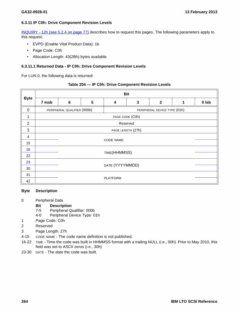
GA32-0928-01 13 February 2013
6.3.11 IP C0h: Drive Component Revision Levels
INQUIRY - 12h (see 5.2.4 on page 77) describes how to request this pages. The following parameters apply to this request:
• EVPD (Enable Vital Product Data): 1b
• Page Code: C0h
• Allocation Length: 43(2Bh) bytes available
6.3.11.1 Returned Data - IP C0h: Drive Component Revision Levels
For LUN 0, the following data is returned:
Byte Description
0 Peripheral DataBit Description7-5 Peripheral Qualifier: 000b4-0 Peripheral Device Type: 01h
1 Page Code: C0h2 Reserved3 Page Length: 27h4-15 CODE NAME - The code name definition is not published.16-22 TIME - Time the code was built in HHMMSS format with a trailing NULL (i.e., 00h). Prior to May 2010, this
field was set to ASCII zeros (i.e., 30h)23-30 DATE - The date the code was built.
Table 204 — IP C0h: Drive Component Revision Levels
ByteBit
7 msb 6 5 4 3 2 1 0 lsb
0 PERIPHERAL QUALIFIER (000b) PERIPHERAL DEVICE TYPE (01h)
1 PAGE CODE (C0h)
2 Reserved
3 PAGE LENGTH (27h)
4CODE NAME
15
16TIME(HHMMSS)
22
23DATE (YYYYMMDD)
30
31PLATFORM
42
264 IBM LTO SCSI Reference
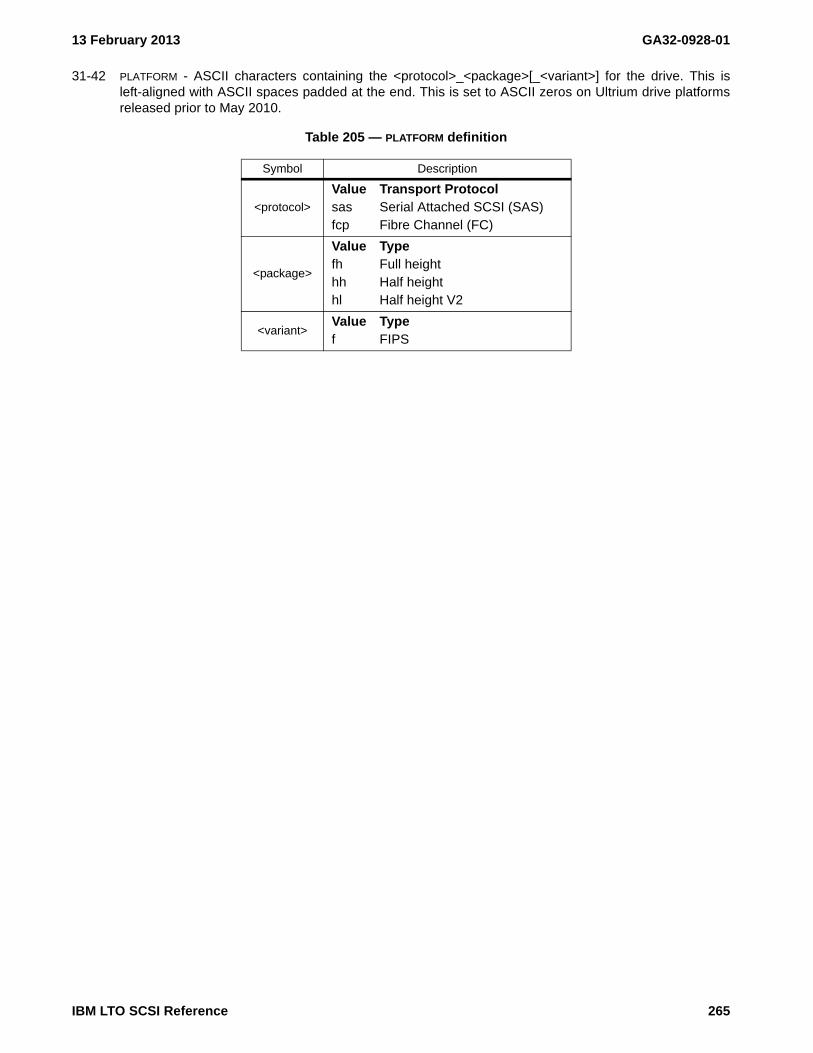
13 February 2013 GA32-0928-01
31-42 PLATFORM - ASCII characters containing the <protocol>_<package>[_<variant>] for the drive. This isleft-aligned with ASCII spaces padded at the end. This is set to ASCII zeros on Ultrium drive platformsreleased prior to May 2010.
Table 205 — PLATFORM definition
Symbol Description
<protocol>
Value Transport Protocolsas Serial Attached SCSI (SAS)fcp Fibre Channel (FC)
<package>
Value Typefh Full heighthh Half heighthl Half height V2
<variant>Value Typef FIPS
IBM LTO SCSI Reference 265

GA32-0928-01 13 February 2013
6.3.12 IP C1h: Drive Serial Numbers
INQUIRY - 12h (see 5.2.4 on page 77) describes how to request this pages. The following parameters apply to this request:
• EVPD (Enable Vital Product Data): 1b
• Page Code: C1h
• Allocation Length: 1Ch (28) bytes available
6.3.12.1 Returned Data - IP C1h: Drive Serial Numbers
For LUN 0, the following data is returned:
Byte Description
0 Peripheral DataBit Description7-5 Peripheral Qualifier: 000b4-0 Peripheral Device Type: 01h
1 Page Code: C1h2 Reserved3 Page Length: 18h4-15 Manufacturing Serial Number (set at time of manufacture), right-justified with leading zeroes, in ASCII16-27 Reported Serial Number over the primary interface (e.g. Inquiry pages 80h and 83h), right-justified with
leading zeroes, in ASCII
Table 206 — Inquiry Page C1h: Drive Serial Numbers
ByteBit
7 6 5 4 3 2 1 0
0 Peripheral Qualifier (000b) Peripheral Device Type (01h)
1 Page Code (C1h)
2 Reserved
3 Page Length (18h)
4Manufacturing Serial Number
15
16Reported Serial Number
27
266 IBM LTO SCSI Reference

13 February 2013 GA32-0928-01
6.3.13 IP C7h: Device Unique Configuration Data
This page provides data required by IBM eServers for connection to the drive.
INQUIRY - 12h (see 5.2.4 on page 77) describes how to request this pages. The following parameters apply to this request:
• EVPD (Enable Vital Product Data): 1b
• Page Code: C7h
• Allocation Length: 117 (75h) bytes available
6.3.13.1 Returned Data - IP C7h: Device Unique Configuration Data
The Device Unique Configuration Data Page is supported on IBM eServer capable drives only. On drives that are not eServer capable this page will be returned with all zero data.
IBM LTO SCSI Reference 267

GA32-0928-01 13 February 2013
6.3.14 IP C8h: Mode Parameter Default Settings
This page provides data required by IBM eServers for connection to the drive.
INQUIRY - 12h (see 5.2.4 on page 77) describes how to request this pages. The following parameters apply to this request:
• EVPD (Enable Vital Product Data): 1b
• Page Code: C8h
• Allocation Length: 51 (33h) bytes available
6.3.14.1 Returned Data - IP C8h: Mode Parameter Default Settings
The Mode Parameter Default Settings page is supported on IBM eServer capable drives only. On drives that are not eServer capable this page will be returned with all zero data. For LUN 0, the following data is returned on eServer capable drives only.
268 IBM LTO SCSI Reference

13 February 2013 GA32-0928-01
6.4 Log Parameters (LP)
Log parameters are used in relation to LOG SELECT - 4Ch (see 5.2.7 on page 87) commands and LOG SENSE - 4Dh (see 5.2.8 on page 88) commands.
Index Of Counters (log parameters not in counter format are not included) (see on page 507) provides an alphabetized list of all counter type log parameters and may be useful in finding parameters that provide the information desired.
6.4.1 Log Page Format
Each log page begins with a four-byte page header followed by zero or more variable-length log parameters defined for that log page. The log page format is defined in table 207.
If the SPF bit is set to 0 then the Subpage Code field is reserved and is set to zero. If the SPF bit is set to one, then the subpage format is being used and the Subpage Code field is used to determine which log parameters are to be returned.
Table 207 — Log page format
ByteBit
7 msb 6 5 4 3 2 1 0 lsb
0 DS SPF PAGE CODE
1 SUBPAGE CODE
2 (MSB)PAGE LENGTH (n-3)
3 (LSB)
Log parameter(s) (see 6.4.2)
4Log parameter (First)
.
.
Log parameter (Last)n
IBM LTO SCSI Reference 269

GA32-0928-01 13 February 2013
6.4.2 Log Parameter Format
Each log parameter begins with a 4-byte parameter header, followed by 1 or more bytes of parameter data. Table 208 shows the log parameter format. The fields of byte 2 are described under clause 6.4.2.1.
6.4.2.1 Log Parameter Byte 2 — Control Byte
A Log Parameter Control Byte is returned for each parameter code described in the log pages. The Log Parameter Control Byte is described here one time only. Any parameters using a different Log Parameter Control Byte have that byte described within that parameter.
The contents of this byte are constant; the user cannot set these values. This byte is part of the returned data described in the SCSI standard; it is described in the following list:
Bit Description7 DU (Disable Update): 0b6 DS (Disable Save): 1b5 TSD (Target Save Disable): 1b4 ETC (Enable Threshold Comparison): 0b3-2 TMC (Threshold Met Comparison): 00b1 Rsvd (Reserved)0 LP (List Parameter): 0b (indicates this is a log counter)
Table 208 — Log Parameter Format
ByteBit
7 msb 6 5 4 3 2 1 0 lsb
0 MSBPARAMETER CODE
1 LSB
2 DU DS TSD ETC TMC Rsvd LP
3 PARAMETER LENGTH (n-3)
4 MSBParameter Value
n LSB
270 IBM LTO SCSI Reference

13 February 2013 GA32-0928-01
6.4.3 General Log Parameter Reset Behavior
Unless otherwise specified, each log counter is reset when read by the Log Sense command. Specific exceptions include Pages 30h, 37h, and 3Dh. Several pages have values which are reset at load time, as specified.
WARNING WARNINGThe parameters in log pages should be dynamically parsed as some parameters may not be present and new parameters may be insterted. The relative location of parameters have changed and are anticipated to continue
WARNING WARNING
to change.
IBM LTO SCSI Reference 271

GA32-0928-01 13 February 2013
6.4.4 LP 00h: Supported Log Pages
See LOG SELECT - 4Ch (see 5.2.7 on page 87) and LOG SENSE - 4Dh (see 5.2.8 on page 88) for directions on how to use this page. This log page returns the list of log pages supported. There may be log pages which can be read or reset which are not included in this list. Such pages are for engineering or manufacturing use and are not intended for general use. This page does not contain any log parameters.
6.4.4.1 Parameter Reset Behavior (00h)
This data can be neither reset nor written.
6.4.4.2 Parameter Definitions (00h)
Byte Description
0Bit Description7-6 Reserved5-0 Page Code (000000b)
1 Reserved2-3 Page Length (n-3)4-n Supported Log Pages: This field is a list of 1-byte log page codes and may include some or all of the
following:Code Log Page00h LP 00h: Supported Log Pages (see 6.4.4 on page 272)02h LP 02h: Write Error Counters (see 6.4.5 on page 273)03h LP 03h: Read Error Counters (see 6.4.6 on page 274)06h LP 06h: Non-Medium Errors (see 6.4.7 on page 275)0Ch LP 0Ch: Sequential-Access Device (see 6.4.8 on page 276)11h LP 11h: DT Device Status (see 6.4.9 on page 278)14h LP 14h: Device Statistics (see 6.4.10 on page 289)16h LP 16h: Tape diagnostic data (see 6.4.11 on page 297)17h LP 17h: Volume Statistics (see 6.4.12 on page 301)18h LP 18h: Protocol-specific port (see 6.4.13 on page 308)1Ah LP 1A: Power Condition Transitions (see 6.4.15 on page 315)1Bh LP 1Bh: Data Compression (see 6.4.14 on page 312)2Eh LP 2Eh: TapeAlerts (see 6.4.16 on page 316)30h LP 30h: Tape Usage (see 6.4.17 on page 319)31h LP 31h: Tape capacity (see 6.4.18 on page 320)32h LP 32h: Data compression (see 6.4.19 on page 321)33h LP 33h: Write Errors (see 6.4.20 on page 322)34h LP 34h: Read Forward Errors (see 6.4.21 on page 324)37h LP 37h: Performance Characteristics (see 6.4.22 on page 326)38h LP 38h: Blocks/Bytes Transferred (see 6.4.23 on page 338)39h LP 39h: Host Port 0 Interface Errors (see 6.4.24 on page 340)3Bh LP 3Bh: Host Port 1 Interface Errors (see 6.4.26 on page 342)3Ch LP 3Ch: Drive usage information (see 6.4.27 on page 343)3Dh LP 3Dh: Subsystem Statistics (see 6.4.28 on page 345)
NOTE 39 - LP 3Ah: Drive control verification (see 6.4.25 on page 341), LP 3Eh: Engineering Use (see 6.4.29 on page 347) and LP 3Eh[3Ch]: Drive Control Statistics (see 6.4.30 on page 348) are for engineering use only and are not reported as a supported log page, but can be used with Log Sense and Log Select commands.
An Index Of Counters may be found at the end of this clause. Log parameters that are not in counter format are not included in this list.
272 IBM LTO SCSI Reference

13 February 2013 GA32-0928-01
6.4.5 LP 02h: Write Error Counters
See LOG SELECT - 4Ch (see 5.2.7 on page 87) and LOG SENSE - 4Dh (see 5.2.8 on page 88) for directions on how to use this page. This page is for Write Errors.
6.4.5.1 Parameter Reset Behavior (02h)
Parameters in this page are reset when a cartridge is loaded.
This data can be reset to zero, but cannot be written.
6.4.5.2 Parameter Definitions (02h)
Parameters 0000h through 0002h are not supported and are returned as 0000_0000h.
WARNING WARNINGThe parameters in log pages should be dynamically parsed as some parameters may not be present and new parameters may be insterted. The relative location of parameters have changed and are anticipated to continue
WARNING WARNING
to change.
Table 209 — LP 02h: Write Error Log Parameters
Parameter Code(in Hex)
Counter: Description Size
0000h Not supported 4
0001h Not supported 4
0002h Not supported 4
0003hTotal Corrected Write Errors {02h:0003h}: These errors are corrected by ECC and do not require error recovery procedures (ERPs). Each count represents one block in error that was corrected and written.
4
0004h Total Write Retries {02h:0004h}: 4
0005h
Total Write Kebibytes Processed {02h:0005h}: Each count represents a kebibyte (1024 bytes) of data processed across the host interface during write-type commands. The count does not include ERP retries. This field is identical to the Host Write Kebibytes Processed field of Page Code 38h, parameter code 0001h.
4
0006h
Total Uncorrected Write Errors {02h:0006h}: The total number of write errors that could not be corrected by ECC, no servo error was reported, and the error was not a transient error. Each count represents one block in error that was not corrected, but was recovered by ERPs and successfully written.
4
8000h Unspecified 8
8001h Unspecified 4
IBM LTO SCSI Reference 273

GA32-0928-01 13 February 2013
6.4.6 LP 03h: Read Error Counters
See LOG SELECT - 4Ch (see 5.2.7 on page 87) and LOG SENSE - 4Dh (see 5.2.8 on page 88) for directions on how to use this page. This page is for Read Errors.
6.4.6.1 Parameter Reset Behavior (03h)
Parameters in this page are reset when a cartridge is loaded.
This data can be reset to zero, but cannot be written.
6.4.6.2 Parameter Definitions (03h)
Parameters 0000h through 0002h are not supported and are returned as 0000_0000h.
WARNING WARNINGThe parameters in log pages should be dynamically parsed as some parameters may not be present and new parameters may be insterted. The relative location of parameters have changed and are anticipated to continue
WARNING WARNING
to change.
Table 210 — LP 03h: Read Error Log Parameters
ParameterCode
Counter: Description Size
0000h Not supported 4
0001h Not supported 4
0002h Not supported 4
0003hTotal Corrected Read Errors {03h:0003h}: These are errors that are corrected by ECC and do not require error recovery procedures (ERPs). Each count represents one block in error that was corrected and read.
4
0004h Total Read Retries {03h:0004h}: 4
0005h
Total Read Kebibytes Processed {03h:0005h}: Each count represents a kebibyte (1024 bytes) processed across the host interface during read-type commands. The count does not include ERP retries. This field is identical to the Host Read Kebibytes Processed field of Page Code 38h, parameter code 0003h.
4
0006h
Total Uncorrected Read Errors {03h:0006h}: The total number of read errors that could not be corrected by ECC, no servo error was reported, and the error was not a transient error. Each count represents one block in error that was not corrected, but was recovered by ERPs and successfully read.
4
8000h Unspecified 8
274 IBM LTO SCSI Reference
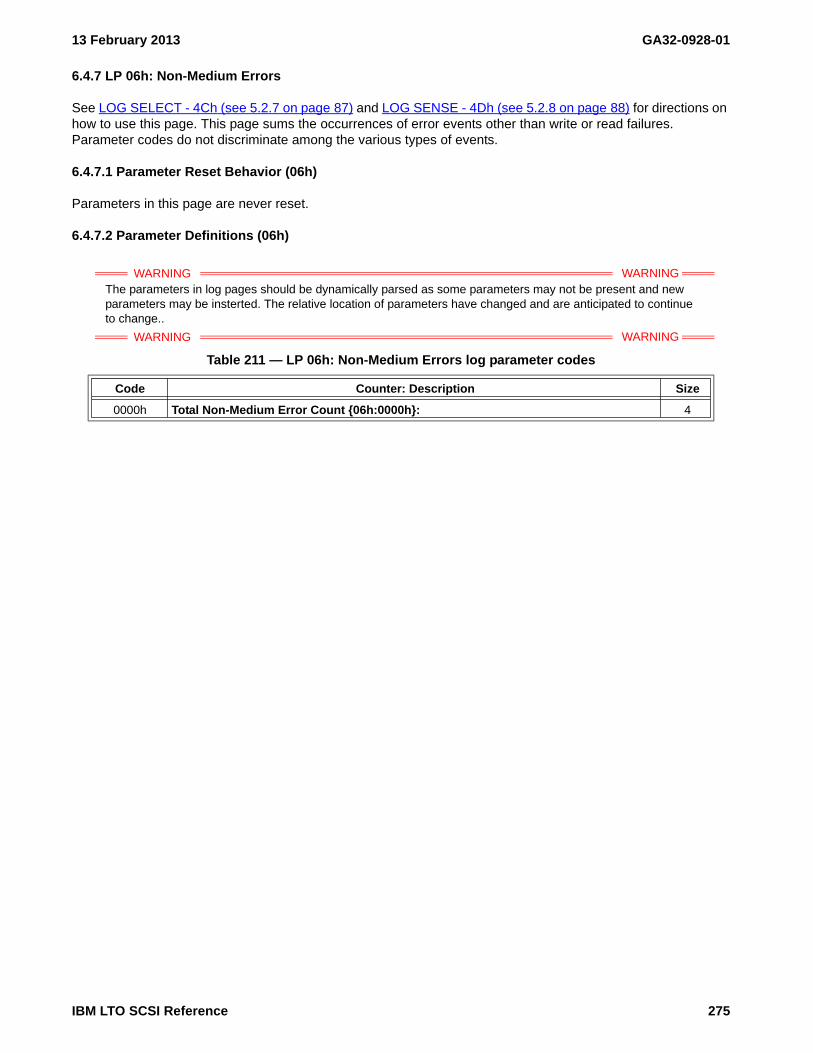
13 February 2013 GA32-0928-01
6.4.7 LP 06h: Non-Medium Errors
See LOG SELECT - 4Ch (see 5.2.7 on page 87) and LOG SENSE - 4Dh (see 5.2.8 on page 88) for directions on how to use this page. This page sums the occurrences of error events other than write or read failures. Parameter codes do not discriminate among the various types of events.
6.4.7.1 Parameter Reset Behavior (06h)
Parameters in this page are never reset.
6.4.7.2 Parameter Definitions (06h)
WARNING WARNINGThe parameters in log pages should be dynamically parsed as some parameters may not be present and new parameters may be insterted. The relative location of parameters have changed and are anticipated to continue
WARNING WARNING
to change..
Table 211 — LP 06h: Non-Medium Errors log parameter codes
Code Counter: Description Size
0000h Total Non-Medium Error Count {06h:0000h}: 4
IBM LTO SCSI Reference 275

GA32-0928-01 13 February 2013
6.4.8 LP 0Ch: Sequential-Access Device
See LOG SELECT - 4Ch (see 5.2.7 on page 87) and LOG SENSE - 4Dh (see 5.2.8 on page 88) for directions on how to use this page. This page is for counters specific to tape drives.
6.4.8.1 Parameter Reset Behavior (0Ch)
Parameters in this page are reset on load.
6.4.8.2 Parameter Definitions (0Ch)
WARNING WARNINGThe parameters in log pages should be dynamically parsed as some parameters may not be present and new parameters may be insterted. The relative location of parameters have changed and are anticipated to continue
WARNING WARNING
to change.
Table 212 — LP 0Ch: Sequential-Access Device log parameters (part 1 of 2)
Code Counter: Description Length
0000hTotal Channel Write Bytes {0Ch:0000h}: The total number of bytes of data written from the host on this mount.
8
0001hTotal Device Write Bytes {0Ch:0001h}: The total number of bytes of data written to tape on this mount, not counting ECC and formatting overhead. This is the number of data bytes after compression.
8
0002hTotal Device Read Bytes {0Ch:0002h}: The total number of bytes of data read from tape on this mount, not counting ECC and formatting overhead. This is the number of compressed data bytes read from media before decompression.
8
0003hTotal Channel Read Bytes {0Ch:0003h}: The total number of bytes of data read to the host on this mount.
8
0004h
Approximate native capacity from BOP to EOD {0Ch:0004h}: This is in megabytes (i.e., 106). This is not sensitive to the current position of the medium. The approximate native capacity between EOD and EW is the difference of parameter 0005h and this parameter. Conditions may occur that reduce the amount of data that is written before reaching EW. EOD may be beyond LEOP. A value of all bits set to one indicates that this information is invalid (e.g., no volume is mounted, EOD information needs to be rebuilt).
4
0005hApproximate native capacity between BOP and EW of the current partition {0Ch:0005h}: This is in megabytes (i.e., 106). If no volume is mounted or this value is unknown the device server shall set all bits in this parameter to one.
4
0006hMinimum native capacity between EW and LEOP of the current partition {0Ch:0006h}: This is in megabytes (i.e., 106). If no volume is mounted the device server shall set all bits in this parameter to one.
4
0007hApproximate native capacity from BOP to the current position of the medium {0Ch:0007h}: This is in megabytes (i.e., 106). If no volume is mounted the device server shall set all bits in this parameter to one.
4
0008h
Maximum native capacity that is currently allowed to be in the device object buffer {0Ch:0008h}: This is in megabytes (i.e., 106). This value may change depending on the current position of the medium (e.g., available native capacity may decrease as the current position of the medium approaches LEOP).
4
0100hCleaning Requested {0Ch:0100h}: A non-zero value indicates a cleaning action is requested by the drive.
8
276 IBM LTO SCSI Reference

13 February 2013 GA32-0928-01
8000hTotal Megabytes Processed Since Cleaning {0Ch:8000h}: Number of megabytes (106) processed to tape since last cleaning (written after compression/read before decompression)
4
8001hLifetime load cycles {0Ch:8001h}: This is the number of times the drive has been loaded in its lifetime.
4
8002hLifetime cleaning cycles {0Ch:8002h}: This is the number of times over its lifetime the drive has been cleaned using a cleaner cartridge.
4
8003hLifetime Power-on time {0Ch:8003h}: This is the number of seconds the drive has been powered on over its lifetime.
4
Table 212 — LP 0Ch: Sequential-Access Device log parameters (part 2 of 2)
Code Counter: Description Length
IBM LTO SCSI Reference 277

GA32-0928-01 13 February 2013
6.4.9 LP 11h: DT Device Status
See LOG SELECT - 4Ch (see 5.2.7 on page 87) and LOG SENSE - 4Dh (see 5.2.8 on page 88) for directions on how to use this page.
The DT Device Status log page (see table 213) defines log information pertaining to the DT device (i.e. tape drive) and DT device primary ports.
Byte Description
0Bit Description7-6 Reserved5-0 Page Code (11h)
1 Reserved2-3 Page Length (n-3)4-n DT Device Status log parameters(see 6.4.9.2).
6.4.9.1 Parameter Reset Behavior (11h)
6.4.9.2 Parameter Definitions (11h)
WARNING WARNINGThe parameters in log pages should be dynamically parsed as some parameters may not be present and new parameters may be insterted. The relative location of parameters have changed and are anticipated to continue
WARNING WARNING
to change.
DT Device Status log parameters are shown in table 214.
Table 213 — LP 11h: DT Device Status log page
ByteBit
7 msb 6 5 4 3 2 1 0 lsb
0 Reserved PAGE CODE (11h)
1 Reserved
2 (MSB)PAGE LENGTH (n-3)
3 (LSB)
4DT Device Status log parameters
n
Table 214 — DT Device Status log parameters
Parameter Code Description
0000h Very high frequency data: (see 6.4.9.2.1)
0001h Very high frequency polling delay: (see 6.4.9.2.2)
0002h to 0003h Reserved
0100h Obsolete
0101h - 01FFh DT device primary port status: (see 6.4.9.2.3)
8000h to FFFFh Vendor-specific
278 IBM LTO SCSI Reference
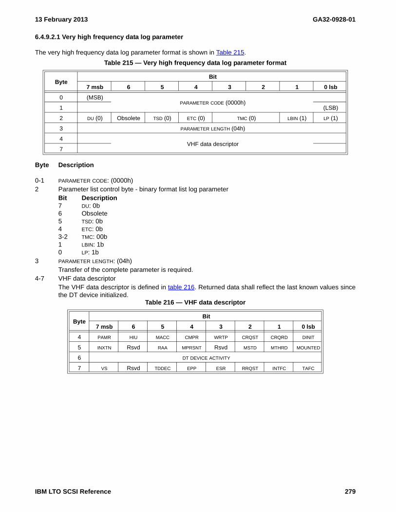
13 February 2013 GA32-0928-01
6.4.9.2.1 Very high frequency data log parameter
The very high frequency data log parameter format is shown in Table 215.
Byte Description
0-1 PARAMETER CODE: (0000h)2 Parameter list control byte - binary format list log parameter
Bit Description7 DU: 0b6 Obsolete5 TSD: 0b4 ETC: 0b3-2 TMC: 00b1 LBIN: 1b0 LP: 1b
3 PARAMETER LENGTH: (04h)Transfer of the complete parameter is required.
4-7 VHF data descriptorThe VHF data descriptor is defined in table 216. Returned data shall reflect the last known values sincethe DT device initialized.
Table 215 — Very high frequency data log parameter format
ByteBit
7 msb 6 5 4 3 2 1 0 lsb
0 (MSB)PARAMETER CODE (0000h)
1 (LSB)
2 DU (0) Obsolete TSD (0) ETC (0) TMC (0) LBIN (1) LP (1)
3 PARAMETER LENGTH (04h)
4VHF data descriptor
7
Table 216 — VHF data descriptor
ByteBit
7 msb 6 5 4 3 2 1 0 lsb
4 PAMR HIU MACC CMPR WRTP CRQST CRQRD DINIT
5 INXTN Rsvd RAA MPRSNT Rsvd MSTD MTHRD MOUNTED
6 DT DEVICE ACTIVITY
7 VS Rsvd TDDEC EPP ESR RRQST INTFC TAFC
IBM LTO SCSI Reference 279

GA32-0928-01 13 February 2013
NOTE 40 - In addition to reliance on indication of initialization completion, reliance on returned values should alsotake into consideration conditions indicated by changes in Tape Alert flag status, and process those first as needed.
Byte Description
4Bit Description7 PAMR(prevent/allow medium removal):
Value Description0b Medium removal is not prevented as the result of a PREVENT/ALLOW MEDIUM
REMOVAL command on LUN 0.1b Medium removal is prevented as the result of a PREVENT/ALLOW MEDIUM
REMOVAL command on LUN 0.6 HIU(host initiated unload):
Value Description0b Volume is not in an unload state due to a LOAD UNLOAD command.1b Volume is unloaded due to a LOAD UNLOAD command on LUN 0.
5 MACC (medium auxiliary memory accessible): Value Description0b Medium Auxiliary Memory (MAM) is not accessible.1b Medium Auxiliary Memory (MAM) is accessible.
4 CMPR (compress): Value Description0b Data compression is not enabled.1b Data compression is enabled.
3 WRTP (write protect): only valid if the MPRSNT bit is set to one.Value Description0b Volume is not physically write protected.1b Volume is physically write protected.
2 CRQST (cleaning requested): Value Description0b Cleaning not requested.1b Cleaning requested.
1 CRQRD (cleaning required): Value Description0b Cleaning not required; normal operation possible without cleaning.1b Cleaning required; normal operation may not be possible until drive is cleaned.
0 DINIT (DT device initialized): Value Description0b DT device initialization is required or incomplete. VHF data not valid.1b VHF data valid
280 IBM LTO SCSI Reference

13 February 2013 GA32-0928-01
5Bit Description7 INXTN (in transition): Indicates the stability of the other bits in this byte (i.e., byte 5) and whether
state transitions are taking place.Value Description0b Device is in the state reflected by the remaining bits in this byte and is making no
attempt to leave this state.1b Device is transitioning to another state; other bits in this byte are in transition.
6 Rsvd (Reserved)5 RAA (robotic access allowed):
Value Description0b Library or Medium Changer should not move a volume to or from the device.1b Library or Medium Changer may move a volume to or from the device.
4 MPRSNT (medium present): Value Description0b The device does not detect a volume present.1b The device detects a volume present.
3 Rsvd (Reserved)2 MSTD (medium seated):
Value Description0b Cartridge is not seated; further mechanical motion remains in order to complete
the loading process, exclusive of tape threading.1b Cartridge is mechanically seated within the loading mechanism (i.e., the physical
loading process has completed).1 MTHRD (medium threaded):
The value of the MTHRD bit may or may not correspond to the device responding with a status of GOOD to a TEST UNIT READY command, as additional processing may be required by the device after threading before the logical unit becomes ready.
Value Description0b Medium is not threaded.1b Medium has been threaded; tape motion operations are possible.
The value of the MTHRD bit may or may not correspond to the DT device responding with a status of GOOD to a TEST UNIT READY command, as additional processing may be required by the DT device after threading before the logical unit becomes ready.
0 MOUNTED: Value Description0b Volume is not mounted.1b Volume is mounted. The drive may be able to respond to a TEST UNIT READY
command with GOOD status, however when a cleaning cartridge or microcode update cartridge is loaded the drive may respond to a TEST UNIT READY com-mand with a CHECK CONDITON with the sense key set to NOT READY.
IBM LTO SCSI Reference 281

GA32-0928-01 13 February 2013
6 DT DEVICE ACTIVITY: This field is used to describe the current activity of the deviceValue Description00h No DT device activity01h Cleaning operation in progress02h Medium is being loaded03h Medium is being unloaded04h Other medium activity05h Reading from medium06h Writing to medium07h Locating medium08h Rewinding medium09h Erasing medium0Ah Formatting medium0Bh Calibrating medium0Ch Other DT device activity0Dh Microcode update in progress
7Bit Description7 VS: (0b)6-3 Reserved5 TDDEC (tape diagnostic data entry created):
Value Description0b The device has not created a new Tape Diagnostic Data log page entry since the
last retrieval of any of the parameters from the Tape Diagnostic Data log page by this I_T nexus.
1b The device has created a new Tape Diagnostic Data log page entry since the last retrieval of any of the parameters from the Tape Diagnostic Data log page by this I_T nexus.
4 EPP (encryption parameters present): Value Description0b The device does not have a set of saved data encryption parameters with either
the ENCRYPTION MODE field set to a value other than DISABLE or the DECRYPTION MODE field set to a value other than DISABLE
1b The device has a set of saved data encryption parameters with either the ENCRYPTION MODE field set to a value other than DISABLE or the DECRYPTION MODE field set to a value other than DISABLE
3 ESR (encryption service request): Value Description0b At least one bit in the SERVICE REQUEST INDICATORS field in the DT device ADC
data encryption control status log parameter has been set to one since the last retrieval of the DT device ADC data encryption control status log parameter by this I_T nexus and at least one bit in the SERVICE REQUEST INDICATORS field in the DT device ADC data encryption control status log parameter is set to one.
1b No bits in the SERVICE REQUEST INDICATORS field in the DT device ADC data encryption control status log parameters have been set to one since the last retrieval of the DT device ADC data encryption control status log parameter by
282 IBM LTO SCSI Reference

13 February 2013 GA32-0928-01
this I_T nexus or all of the bits in the SERVICE REQUEST INDICATORS field in the DT device ADC data encryption control status log parameter are set to zero.
2 RRQST (recovery requested): Value Description0b No recovery procedure is requested.1b Device has detected an error and one or more requested recovery procedures
are available via the ADC Requested Recovery log page.1 INTFC (interface changed):
Value Description0b No fields in the DT device primary port status log parameters have changed since
the last retrieval of any of the DT device primary port status log parameters from the DT Device Status log page over this I_T nexus.
1b One or more fields in the DT device primary port status log parameters have changed since the last retrieval of any of the DT device primary port status log parameters from the DT Device Status log page over this I_T nexus.
0 TAFC (TapeAlert state flag changed): Value Description0b No TapeAlert state flag has changed since the last retrieval of the TapeAlert
Response log page over this I_T nexus.1b At least one TapeAlert state flag has changed since the last retrieval of the
TapeAlert Response log page over this I_T nexus.
6.4.9.2.2 Very high frequency polling delay log parameter
The very high frequency polling delay log parameter format is shown in Table 217.
Byte Description
0-1 PARAMETER CODE: (0001h)2 Parameter list control byte - binary format list log parameter
Bit Description7 DU: 0b6 Obsolete5 TSD: 0b4 ETC: 0b3-2 TMC: 00b1 LBIN: 1b0 LP: 1b
3 PARAMETER LENGTH: (02h)Transfer of the complete parameter is required.
4-7 VHF POLLING DELAY: The minimum delay in milliseconds before another DT Device Status log pageshould be requested.
Table 217 — Very high frequency polling delay log parameter format
ByteBit
7 msb 6 5 4 3 2 1 0 lsb
0 (MSB)PARAMETER CODE (0001h)
1 (LSB)
2 DU (0) Obsolete TSD (0) ETC (0) TMC (00) LBIN (1) LP (1)
3 PARAMETER LENGTH (02h)
4 (MSB)VHF POLLING DELAY
5 (LSB)
IBM LTO SCSI Reference 283

GA32-0928-01 13 February 2013
6.4.9.2.3 Primary port status log parameter(s)
There is a primary port status log parameter for each primary port of the device. The format is shown in table 218.
Byte Description
0-1 PARAMETER CODE:0100h plus the value of the Relative Target Port field associated with that port. The Relative Target Portis the same as the relative target port value defined in the VPD pages of inquiryValue Description0101h Primary port 1; traditionally known as port 0.0102h Primary port 2; traditionally known as port 1.
2 Parameter list control byte - binary format list log parameterBit Description7 DU: 0b6 Obsolete5 TSD: 0b4 ETC: 0b3-2 TMC: 00b1 LBIN: 1b0 LP: 1b
3 PARAMETER LENGTH: 4-7 Primary port status data: This is determined by the protocol of the port with which the parameter is
associated. The protocol of the port is reported in the PROTOCOL IDENTIFIER field of the Relative targetport identifier designation descriptor of the Device identification VPD page for the associated port.Value Description0h Fibre Channel port status data (see 6.4.9.2.4 on page 285)6h Serial Attached SCSI port status data (see 6.4.9.2.5 on page 287)
Table 218 — Primary port status log parameter(s) format
ByteBit
7 msb 6 5 4 3 2 1 0 lsb
0 (MSB)PARAMETER CODE
1 (LSB)
2 DU (0) Obsolete TSD (0) ETC (0) TMC (00) LBIN (1) LP (1)
3 PARAMETER LENGTH (n-3)
4 (MSB)Primary port status data
n (LSB)
284 IBM LTO SCSI Reference

13 February 2013 GA32-0928-01
6.4.9.2.4 Fibre Channel port status data
The format of the primary port status data for a Fibre Channel port is shown in table 219. This descriptor reports the current operating points of the specified port.
Byte Description
0Bit Description7 CURRTOP (current topology):
This field is undefined when the PIC field is set to zero
Value Description0b Port is currently operating in arbitrated loop mode.1b Port is currently operating in point to point mode.
6-4 CURRENT SPEED: This field is undefined when the PIC field is set to zeroValue Description000b 1 Gb/sec.001b 2 Gb/sec.010b 4 Gb/sec.011b 8 Gb/sec.100b 10 Gb/sec
3 LC (login complete): Value Description0b No host is currently logged in to the drive through this port .1b At least one host is currently logged in to the drive through this port (i.e., has suc-
cessfully completed PRLI and still has an active session).2 CONFLICT:
Value Description0b No AL_PA conflict exists on this port.1b The required Hard AL_PA is in use by another device or no AL_PA is available for
this port.1 SIGNAL:
Value Description0b Signal (i.e., light) is not detected on this port.1b Signal (i.e., light) is detected on this port.
0 PIC (port initialization complete): Value Description
Table 219 — Fibre Channel port status data format
ByteBit
7 msb 6 5 4 3 2 1 0 lsb
0 CURRTOP CURRENT SPEED LC CONFLICT SIGNAL PIC
1CURRENT N_PORT_ID
3
4 ECSV Reserved
5 Reserved EXTENDED CURRENT SPEED
6 Reserved
7 Rsvd CURRENT FC-AL LOOP ID
8CURRENT PORT NAME
15
16CURRENT NODE NAME
23
IBM LTO SCSI Reference 285

GA32-0928-01 13 February 2013
0b The FC_Port state machine is not in the ACTIVE state (if port is operating in point-to-point topology), or has not successfully completed the most recent LIP.
1b The FC_Port state machine is in the ACTIVE state (if port is operating in point-to-point topology), or the most recent LIP has completed successfully.
1-3 CURRENT N_PORT_ID: The 24-bit N_Port_ID that is currently assigned to this port. This field is undefinedwhen the PIC field is set to zero.
4Bit Description7 ECSV (extended current speed valid): 0b6-0 Reserved
5Bit Description7-4 Reserved3-0 EXTENDED CURRENT SPEED: 0h
6 Reserved7
Bit Description7 Reserved6-0 CURRENT FC-AL LOOP ID: The loop identifier assigned to this port. This field is ignored ignored
when the PIC bit is set to zero or when the CURRTOP bit is set to one.8-15 CURRENT PORT NAME: The port’s name identifier (i.e., WWPN).16-23 CURRENT NODE NAME: The device’s node name identifier (i.e., WWNN).
286 IBM LTO SCSI Reference

13 February 2013 GA32-0928-01
6.4.9.2.5 Serial Attached SCSI port status data
The format of the primary port status data for a SAS port is shown in table 220.
Byte Description
0Bit Description7-4 NEGOTIATED PHYSICAL LINK RATE: The negotiated physical link rate of the port.
3-2 Reserved1 SIGNAL:
Value Description0b Signal is not detected by the port.1b Signal is detected by the port.
0 PIC (port initialization complete):Value Description0b The port has not successfully completed the link reset sequence.1b The port has successfully completed the link reset sequence and is ready to
accept connection requests.
Table 220 — Serial Attached SCSI port status data format
ByteBit
7 msb 6 5 4 3 2 1 0 lsb
0 NEGOTIATED PHYSICAL LINK RATE Reserved SIGNAL PIC
1 (MSB)HASHED SAS ADDRESS
3 (LSB
4 (MSB)SAS ADDRESS
11 (LSB)
Table 221 — NEGOTIATED PHYSICAL LINK RATE values
SP state machine ResetStatus state machine
variableCode Description
UNKNOWN 0h Phy is enabled; unknown physical link rate.
DISABLED 1h Phy is disabled.
PHY_ RESET_ PROBLEM 2h Phy is enabled; a phy reset problem occurred.
SPINUP_HOLD 3h Not Supported
PORT_SELECTOR 4h Not Supported
RESET_IN_PROGRESS 5h Not Supported
UNSUPPORTED_PHY_ATTACHED
6hPhy is enabled; a phy is attached without any commonly supported settings.
Reserved 7h Reserved
G1 8h Phy is enabled; 1.5 Gbps physical link rate.
G2 9h Phy is enabled; 3 Gbps physical link rate.
G3 Ah Phy is enabled; 6 Gbps physical link rate.
Reserved Bh to FhPhy is enabled; reserved for future logical or physical link rates.
IBM LTO SCSI Reference 287

GA32-0928-01 13 February 2013
1-3 HASHED SAS ADDRESS: The 24 bit hashed address that is assigned to the port. The Hashed SAS Addressis based on the WWPN.
4-11 SAS ADDRESS: The SAS address of the port (i.e., WWPN).
288 IBM LTO SCSI Reference

13 February 2013 GA32-0928-01
6.4.10 LP 14h: Device Statistics
See LOG SELECT - 4Ch (see 5.2.7 on page 87) and LOG SENSE - 4Dh (see 5.2.8 on page 88) for directions on how to use this page. This page contains non-volatile information relating to volume usage.
The Device Statistics log page is included in Ultrium 5 and later drives. It is not included in earlier generation drives. The Device Statistics log page (see table 222) defines parameters associated with utilization of the tape device.
See SPC-4 for a description of the DS bit, SPF bit, PAGE CODE field, SUBPAGE CODE field and PAGE LENGTH field.
6.4.10.1 Parameter Reset Behavior (14h)
The reset behavior varies by parameter and is specified in the Persist and Clear columns of (see table 223).
Table 222 — LP 14h: Device Statistics log page
ByteBit
7 msb 6 5 4 3 2 1 0 lsb
ds SPF (0b) PAGE CODE (14h)
SUBPAGE CODE (00h)
(MSB)page length (n-3)
(LSB)
Device Statistics log parameter(s)
Device Statistics log parameter [first] (see table 223)
...n Device Statistics log parameter ]last] (see table 223)
IBM LTO SCSI Reference 289

GA32-0928-01 13 February 2013
6.4.10.2 Parameter Definitions (14h)
WARNING WARNINGThe parameters in log pages should be dynamically parsed as some parameters may not be present and new parameters may be insterted. The relative location of parameters have changed and are anticipated to continue
WARNING WARNING
to change.
Table 223 specifies the Device Statistics log page parameter codes.
Table 223 — LP14h: Device Statistics log parameter codes (part 1 of 4)
ParameterCode
Description Type Persist Clear Size
0000hLifetime volume loads {14h:0000h}: Total number of successful load operations.
C P N 4
0001hLifetime cleaning operations {14h:0001h}: Total number of successful and failed cleaning operations.
C P N 4
0002hLifetime power on hours {14h:0002h}: Total number of hours the device has been powered on. The value reported shall be rounded up to the next full hour.
C P N 4
0003h
Lifetime medium motion (i.e., head) hours {14h:0003h}: Total number of hours that the device has spent processing commands that require medium motion. The value reported shall be rounded up to the next full hour.
C P N 4
0004hLifetime meters of tape processed {14h:0004h}: Total number of meters of tape that have been processed by the drive mechanism in either direction.
C P N 4
0005h
Lifetime medium motion (head) hours when incompatible medium was last loaded {14h:0005h}: The value that would have been reported in a lifetime medium motion (head) hours parameter at the time when an incompatible volume was last loaded.
C P N 4
0006h
Lifetime power on hours when the last temperature condition occurred (i.e., TapeAlert code 24h) {14h:0006h}: The value that would have been reported in a lifetime power on hours parameter at the time when the TapeAlert code 24h flag was last set.
C P N 4
0007h
Lifetime power on hours when the last power consumption condition occurred (i.e., TapeAlert code 1Ch) {14h:0007h}: The value that would have been reported in a lifetime power on hours parameter at the time when the TapeAlert code 1Ch flag was last set.
C P N 4
Type DescriptionC Device statistics data counter log parameter (see 6.4.10.3.1)M Device statistics medium type log parameter (see 6.4.10.3.2)S Device statistics string data log parameter (see 6.4.10.3.3)Persist DescriptionP Parameter shall be Persistent across I_T nexus loss, logical unit reset, and power-onV The persistence of this parameter varies and is inherited from the value being reported D The parameter is a duty cycle parameter and is cleared when parameter 0010h (i.e., Duty cycle sample
time {14h:0010h}:) is clearedClear DescriptionN Parameter shall not be cleared by use of a LOG SELECT commandY Parameter may be cleared by use of a LOG SELECT command
a n = Number of Medium Types supported
290 IBM LTO SCSI Reference

13 February 2013 GA32-0928-01
0008h
Medium motion (i.e., head) hours since last successful cleaning operation {14h:0008h}: Count of hours that medium has been in motion in either direction since the last successful cleaning operation. The value reported shall be rounded up to the next full hour.
C P N 4
0009h
Medium motion (i.e., head) hours since second to last successful cleaning operation {14h:0009h}: Count of hours that medium has been in motion in either direction since the second to last successful cleaning operation. The value reported shall be rounded up to the next full hour.
C P N 4
000Ah
Medium motion (i.e., head) hours since third to last successful cleaning operation {14h:000Ah}: Count of hours that medium has been in motion in either direction since the third to last successful cleaning operation. The value reported shall be rounded up to the next full hour.
C P N 4
000Bh
Lifetime power on hours when the last operator initiated forced reset and/or emergency eject occurred {14h:000Bh}: The value that would have been reported in a lifetime power on hours parameter at the time of the last forced reset and/or emergency eject.
C P N 4
000ChLifetime power cycles {14h:000Ch}: Total number of times the drive has detected a power-on event.
C P N 4
000Dh
Volume loads since last parameter reset {14h:000Dh}: Count of successful volume loads since the last time this parameter was reset to zero by use of a LOG SELECT command. This parameter should be retained across a power cycle.
C P Y 4
000Eh
Hard write errors {14h:000Eh}: Number of times that a write type command has terminated with a CHECK CONDITION status having the sense key set to MEDIUM ERROR or HARDWARE ERROR since the last time this parameter was reset to zero by the use of a LOG SELECT command.
C P Y 4
000Fh
Hard read errors {14h:000Fh}: Number of times that a read type command has terminated with a CHECK CONDITION status having the sense key set to MEDIUM ERROR or HARDWARE ERROR since the last time this parameter was reset to zero by the use of a LOG SELECT command.
C P Y 4
Table 223 — LP14h: Device Statistics log parameter codes (part 2 of 4)
ParameterCode
Description Type Persist Clear Size
Type DescriptionC Device statistics data counter log parameter (see 6.4.10.3.1)M Device statistics medium type log parameter (see 6.4.10.3.2)S Device statistics string data log parameter (see 6.4.10.3.3)Persist DescriptionP Parameter shall be Persistent across I_T nexus loss, logical unit reset, and power-onV The persistence of this parameter varies and is inherited from the value being reported D The parameter is a duty cycle parameter and is cleared when parameter 0010h (i.e., Duty cycle sample
time {14h:0010h}:) is clearedClear DescriptionN Parameter shall not be cleared by use of a LOG SELECT commandY Parameter may be cleared by use of a LOG SELECT command
a n = Number of Medium Types supported
IBM LTO SCSI Reference 291
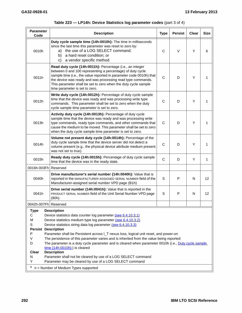
GA32-0928-01 13 February 2013
0010h
Duty cycle sample time {14h:0010h}: The time in milliseconds since the last time this parameter was reset to zero by:
a) the use of a LOG SELECT command;b) a hard reset condition; orc) a vendor specific method
C V Y 6
0011h
Read duty cycle {14h:0011h}: Percentage (i.e., an integer between 0 and 100 representing a percentage) of duty cycle sample time (i.e., the value reported in parameter code 0010h) that the device was ready and was processing read type commands. This parameter shall be set to zero when the duty cycle sample time parameter is set to zero.
C D Y 1
0012h
Write duty cycle {14h:0012h}: Percentage of duty cycle sample time that the device was ready and was processing write type commands. This parameter shall be set to zero when the duty cycle sample time parameter is set to zero.
C D Y 1
0013h
Activity duty cycle {14h:0013h}: Percentage of duty cycle sample time that the device was ready and was processing write type commands, ready type commands, and other commands that cause the medium to be moved. This parameter shall be set to zero when the duty cycle sample time parameter is set to zero.
C D Y 1
0014h
Volume not present duty cycle {14h:0014h}: Percentage of the duty cycle sample time that the device server did not detect a volume present (e.g., the physical device attribute medium present was not set to true).
C D Y 1
0015hReady duty cycle {14h:0015h}: Percentage of duty cycle sample time that the device was in the ready state.
C D Y 1
0016h-003Fh Reserved
0040hDrive manufacturer's serial number {14h:0040h}: Value that is reported in the MANUFACTURER-ASSIGNED SERIAL NUMBER field of the Manufacturer-assigned serial number VPD page (B1h)
S P N 12
0041hDrive serial number {14h:0041h}: Value that is reported in the PRODUCT SERIAL NUMBER field of the Unit Serial Number VPD page (80h).
S P N 12
0042h-007Fh Reserved
Table 223 — LP14h: Device Statistics log parameter codes (part 3 of 4)
ParameterCode
Description Type Persist Clear Size
Type DescriptionC Device statistics data counter log parameter (see 6.4.10.3.1)M Device statistics medium type log parameter (see 6.4.10.3.2)S Device statistics string data log parameter (see 6.4.10.3.3)Persist DescriptionP Parameter shall be Persistent across I_T nexus loss, logical unit reset, and power-onV The persistence of this parameter varies and is inherited from the value being reported D The parameter is a duty cycle parameter and is cleared when parameter 0010h (i.e., Duty cycle sample
time {14h:0010h}:) is clearedClear DescriptionN Parameter shall not be cleared by use of a LOG SELECT commandY Parameter may be cleared by use of a LOG SELECT command
a n = Number of Medium Types supported
292 IBM LTO SCSI Reference

13 February 2013 GA32-0928-01
6.4.10.3 Log parameter formats
6.4.10.3.1 Device statistics data counter log parameter format
The device statistics data counter log parameter is used for reporting parameters specified as device statistics data counter log parameters in (see table 223). The device statistics data counter log parameter format is
0080h
Medium removal prevented {14h:0080h}: A value of 01h indicates that medium removal has been prevented by:
a) a prevention of medium removal condition in the device server,
b) a configuration setting, orc) a vendor specific means.
A value of 00h indicates that medium removal has not been prevented by one of the listed means.An error condition preventing removal of the medium does not cause this parameter to be set to a non-zero value.
C V N 1
0081h
Maximum recommended mechanism temperature exceeded {14h:0081h}: Indicates whether the device has detected at any point in the past that the maximum recommended mechanism temperature has been exceeded.
a) a value of 00h indicates the temperature has not been exceeded;
b) a value of 01h indicates the temperature has been exceeded; and
c) a value of FFh indicates that it is unknown if the temperature has been exceeded.
C P N 1
0082h-0FFFh Reserved
1000hMedium motion (i.e., head) hours for each medium type {14h:1000h}:
M P N 8*n a
1001h-EFFFh Reserved
F000h-FFFFh Vendor-specifc
Table 223 — LP14h: Device Statistics log parameter codes (part 4 of 4)
ParameterCode
Description Type Persist Clear Size
Type DescriptionC Device statistics data counter log parameter (see 6.4.10.3.1)M Device statistics medium type log parameter (see 6.4.10.3.2)S Device statistics string data log parameter (see 6.4.10.3.3)Persist DescriptionP Parameter shall be Persistent across I_T nexus loss, logical unit reset, and power-onV The persistence of this parameter varies and is inherited from the value being reported D The parameter is a duty cycle parameter and is cleared when parameter 0010h (i.e., Duty cycle sample
time {14h:0010h}:) is clearedClear DescriptionN Parameter shall not be cleared by use of a LOG SELECT commandY Parameter may be cleared by use of a LOG SELECT command
a n = Number of Medium Types supported
IBM LTO SCSI Reference 293

GA32-0928-01 13 February 2013
specified in table 224.
Byte Description
0-1 PARAMETER CODE: defined in (see table 223).2 Parameter control byte
Bit Description7 DU (Disable Update):6 Obsolete:5 TSD (Target Save Disable): 0b4 ETC (Enable Threshold Comparison): 0b3-2 TMC (Threshold Met Comparison): 00b1-0 FORMAT AND LINKING: 11b
3 PARAMETER LENGTH: the number of bytes in the device statistics data counter field that follows.4-n DEVICE STATISTICS DATA COUNTER: the value of the data counter associated with the parameter code.
6.4.10.3.2 Device statistics medium type log parameter format
The device statistics medium type log parameter is used for reporting parameters specified as device statistics medium type log parameters in (see table 223). The device statistics medium type log parameter format is specified in table 225.
Byte Description
0-1 PARAMETER CODE: 1000h.
Table 224 — Device statistics data counter log parameter format
ByteBit
7 msb 6 5 4 3 2 1 0 lsb
0 (MSB)PARAMETER CODE
1 (LSB)
2 DU Obsolete TSD (0b) ETC(0b) TMC(00b) FORMAT AND LINKING (11b)
3 PARAMETER LENGTH (n-3)
4 (MSB)DEVICE STATISTICS DATA COUNTER
n (LSB)
Table 225 — Device statistics medium type log parameter format
ByteBit
7 msb 6 5 4 3 2 1 0 lsb
0 (MSB)PARAMETER CODE (1000h)
1 (LSB)
2 DU (0b) Obsolete TSD (0b) ETC (0b) TMC (00b) FORMAT AND LINKING (11b)
3 PARAMETER LENGTH (n-3)
Device statistics medium type descriptor(s)
4 Device statistics medium type descriptor [first] (see table 226)
...
n Device statistics medium type descriptor [last] (see table 226)
294 IBM LTO SCSI Reference

13 February 2013 GA32-0928-01
2 Parameter control byteBit Description7 DU (Disable Update): 0b6 Obsolete:5 TSD (Target Save Disable): 0b4 ETC (Enable Threshold Comparison): 0b3-2 TMC (Threshold Met Comparison): 00b1-0 FORMAT AND LINKING: 11b
3 PARAMETER LENGTH: the number of bytes in the medium type descriptors that follow.4-n Device statistics medium type descriptor(s) : the value of the data counter associated with the parameter
code. The device statistics medium type descriptor is defined in 6.4.10.3.2.1.
6.4.10.3.2.1 Device statistics medium type descriptor
The device statistics medium type descriptor format is specified in table 226.
Byte Description
0-1 Reserved2 DENSITY CODE: the value returned in the general mode parameter block descriptor.3 MEDIUM TYPE: the value returned in the mode parameter header.4-7 MEDIUM MOTION HOURS: the number of medium motion (i.e., head) hours for the type of medium specified
by the combination of the MEDIUM TYPE field and DENSITY CODE field.
6.4.10.3.3 Device statistics string data log parameter format
The device statistics string data log parameter is used for reporting parameters specified as device statistics string data log parameters in (see table 223). The device statistics string data log parameter format is specified
Table 226 — Device statistics medium type descriptor format
ByteBit
7 msb 6 5 4 3 2 1 0 lsb
0 Reserved
1 Reserved
2 DENSITY CODE
3 MEDIUM TYPE
4 (MSB)MEDIUM MOTION HOURS
7 (LSB)
IBM LTO SCSI Reference 295

GA32-0928-01 13 February 2013
in table 227. The device statistics string data log parameter shall be a multiple of 4 bytes.
Byte Description
0-1 PARAMETER CODE: defined in (see table 223).2 Parameter control byte
Bit Description7 DU (Disable Update): 0b6 Obsolete:5 TSD (Target Save Disable): 0b4 ETC (Enable Threshold Comparison): 0b3-2 TMC (Threshold Met Comparison): 00b1-0 FORMAT AND LINKING: 01b
3 PARAMETER LENGTH: the number of bytes in the data that follows.4-n STRING DATA: an ASCII string describing the device statistics parameter specified by the PARAMETER
CODE value. The string data field is an ASCII data field.
Table 227 — Device statistics string data log parameter format
ByteBit
7 msb 6 5 4 3 2 1 0 lsb
0 (MSB)PARAMETER CODE
1 (LSB)
2 DU (0b) Obsolete TSD (0b) ETC(0b) TMC(00b) FORMAT AND LINKING (01b)
3 PARAMETER LENGTH (n-3)
4 (MSB)STRING DATA
n (LSB)
296 IBM LTO SCSI Reference
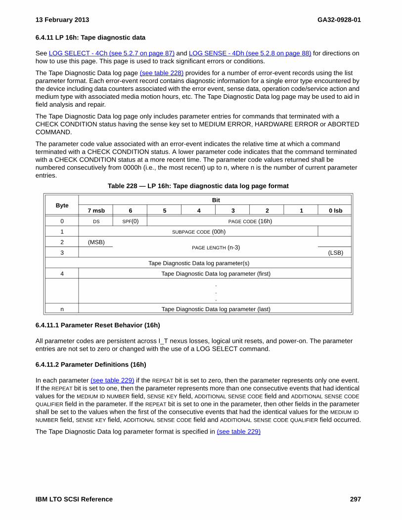
13 February 2013 GA32-0928-01
6.4.11 LP 16h: Tape diagnostic data
See LOG SELECT - 4Ch (see 5.2.7 on page 87) and LOG SENSE - 4Dh (see 5.2.8 on page 88) for directions on how to use this page. This page is used to track significant errors or conditions.
The Tape Diagnostic Data log page (see table 228) provides for a number of error-event records using the list parameter format. Each error-event record contains diagnostic information for a single error type encountered by the device including data counters associated with the error event, sense data, operation code/service action and medium type with associated media motion hours, etc. The Tape Diagnostic Data log page may be used to aid in field analysis and repair.
The Tape Diagnostic Data log page only includes parameter entries for commands that terminated with a CHECK CONDITION status having the sense key set to MEDIUM ERROR, HARDWARE ERROR or ABORTED COMMAND.
The parameter code value associated with an error-event indicates the relative time at which a command terminated with a CHECK CONDITION status. A lower parameter code indicates that the command terminated with a CHECK CONDITION status at a more recent time. The parameter code values returned shall be numbered consecutively from 0000h (i.e., the most recent) up to n, where n is the number of current parameter entries.
6.4.11.1 Parameter Reset Behavior (16h)
All parameter codes are persistent across I_T nexus losses, logical unit resets, and power-on. The parameter entries are not set to zero or changed with the use of a LOG SELECT command.
6.4.11.2 Parameter Definitions (16h)
In each parameter (see table 229) if the REPEAT bit is set to zero, then the parameter represents only one event. If the REPEAT bit is set to one, then the parameter represents more than one consecutive events that had identical values for the MEDIUM ID NUMBER field, SENSE KEY field, ADDITIONAL SENSE CODE field and ADDITIONAL SENSE CODE QUALIFIER field in the parameter. If the REPEAT bit is set to one in the parameter, then other fields in the parameter shall be set to the values when the first of the consecutive events that had the identical values for the MEDIUM ID NUMBER field, SENSE KEY field, ADDITIONAL SENSE CODE field and ADDITIONAL SENSE CODE QUALIFIER field occurred.
The Tape Diagnostic Data log parameter format is specified in (see table 229)
Table 228 — LP 16h: Tape diagnostic data log page format
ByteBit
7 msb 6 5 4 3 2 1 0 lsb
0 DS SPF(0) PAGE CODE (16h)
1 SUBPAGE CODE (00h)
2 (MSB)PAGE LENGTH (n-3)
3 (LSB)
Tape Diagnostic Data log parameter(s)
4 Tape Diagnostic Data log parameter (first)
.
.
.
n Tape Diagnostic Data log parameter (last)
IBM LTO SCSI Reference 297

GA32-0928-01 13 February 2013
WARNING WARNINGThe parameters in log pages should be dynamically parsed as some parameters may not be present and new parameters may be insterted. The relative location of parameters have changed and are anticipated to continue
WARNING WARNING
to change.
Table 229 — Tape diagnostic data log parameter format
ByteBit
7 msb 6 5 4 3 2 1 0 lsb
0 (MSB)Parameter Code
1 (LSB)
2 du(0) Obsolete tsd(0) etc(0) tmc (00b)format and linking
(11b)
3 Parameter Length (n-3)
4 Reserved
5 Reserved
6 Density Code
7 Medium Type
8 (MSB)Lifetime Media Motion Hours
11 (LSB)
12 Reserved
13 Repeat Reserved Sense Key
14 Additional Sense Code
15 Additional Sense Code Qualifier
16 (MSB)Vendor-Specific Code Qualifier
19 (LSB)
20 (MSB)Product Revision Level
23 (LSB)
24 (MSB)Hours Since Last Clean
27 (LSB)
28 Operation Code
29 Reserved Service Action
30 Reserved
31 Reserved
32 (MSB)Medium Id Number
63 (LSB)
64 Reserved Timestamp Origin
65 Reserved
66 (MSB)Timestamp
71 (LSB)
298 IBM LTO SCSI Reference

13 February 2013 GA32-0928-01
Byte Description
0-1 PARAMETER CODE: An indication of the relative time at which the command terminated with this CHECKCONDITION status. A lower parameter code indicates that the command terminated with a CHECKCONDITION status at a more recent time. The parameter code values returned are numberedconsecutively from 0000h (i.e., the most recent) up to n, where n is the number of current parameterentries.
2 Parameter control byteBit Description7 DU (Disable Update): 0b6 Obsolete:5 TSD (Target Save Disable): 0b4 ETC (Enable Threshold Comparison): 0b3-2 TMC (Threshold Met Comparison): 00b1-0 FORMAT AND LINKING: 01b
3 PARAMETER LENGTH: the number of bytes in the data that follows.4-5 Reserved6 DENSITY CODE: The density code of the medium loaded at the time the command terminated with the
CHECK CONDITION status. The DENSITY CODE field is the same value as returned in the general modeparameter block descriptor. If no medium was loaded at the time the command terminated with theCHECK CONDITION status, then the DENSITY CODE field is 00h.
7 MEDIUM TYPE: The type of medium loaded at the time the command terminated with the CHECKCONDITION status. The MEDIUM TYPE field is the same value as returned in the mode parameter header.If no medium was loaded at the time the command terminated with the CHECK CONDITION status, thenthe MEDIUM TYPE is 00h.
8-11 LIFETIME MEDIA MOTION HOURS: The number of media motion (head) hours at the time the commandterminated with the CHECK CONDITION status. The LIFETIME MEDIA MOTION HOURS field is equivalent tothe value contained in LP 14h: Device Statistics (see 6.4.10 on page 289) with a parameter code value of0003h at the time the command terminated with the CHECK CONDITION status.
12 Reserved13
Bit Description7 REPEAT: Indicates if this parameter refers to more than one error event
Value Description0b This parameter represents a single event.1b This parameter represents more than one consecutive events that had identical
values for the MEDIUM ID NUMBER field, SENSE KEY field, ADDITIONAL SENSE CODE field, and ADDITIONAL SENSE CODE QUALIFIER field.
6-4 Reserved3-0 SENSE KEY: The sense key value returned for the command that terminated with the CHECK
CONDITION status.14-15 ADDITIONAL SENSE CODE/ADDITIONAL SENSE CODE QUALIFIER: The additional sense code value returned for
the command that terminated with the CHECK CONDITION status.16-19 VENDOR-SPECIFIC CODE QUALIFIER: The Last Error FSC and Last Error Flag Data (i.e. bytes 65-68 of
Sense Data) generated for the command that terminated with the CHECK CONDITION status.20-23 PRODUCT REVISION LEVEL: The product revision level (i.e., bytes 16-31 of Standard Inquiry) at the time the
command terminated with the CHECK CONDITION status.24-27 HOURS SINCE LAST CLEAN: The time in media motion (i.e., head) hours since the last successful cleaning
at the time the command terminated with the CHECK CONDITION status. The HOURS SINCE LAST CLEAN
field is equivalent to the value contained in the Device Statistics log page with a parameter code of 0008hat the time the command terminated with the CHECK CONDITION status.
28 OPERATION CODE: The operation code of the command that terminated with the CHECK CONDITIONstatus.
IBM LTO SCSI Reference 299

GA32-0928-01 13 February 2013
29Bit Description7-5 Reserved4-0 SERVICE ACTION: if applicable, the service action of the command that terminated with the
CHECK CONDITION status.30-31 Reserved32-63 MEDIUM ID NUMBER: If medium was present at the time the command terminated with the CHECK
CONDITION status, then this field contains (in prioritized order):1) the BARCODE field value contained in the medium auxiliary memory;2) the MEDIUM SERIAL NUMBER field value contained in the medium auxiliary memory; or3) the VOLUME IDENTIFIER field value contained in the medium auxiliary memory.
If no medium was present at the time the command terminated with the CHECK CONDITION status, thethis field is filled with 20h (i.e., ASCII space).
64Bit Description7-3 Reserved2-0 TIMESTAMP ORIGIN: The timestamp origin maintained by the tape drive at the time the command
terminated with the CHECK CONDITION status.65 Reserved66-71 TIMESTAMP: The timestamp maintained by the tape drive at the time the command terminated with the
CHECK CONDITION status.
300 IBM LTO SCSI Reference

13 February 2013 GA32-0928-01
6.4.12 LP 17h: Volume Statistics
See LOG SELECT - 4Ch (see 5.2.7 on page 87) and LOG SENSE - 4Dh (see 5.2.8 on page 88) for directions on how to use this page. This page contains non-volatile information relating to volume usage.
The Volume Statistics log page is included in Ultrium 5 and later drives. It is not included in earlier generation drives.
The Volume Statistics log page (see table 242) defines data parameters associated with utilization of the tape volume and the medium within the volume. Volume statistics for the most recent mounted volume are reported in the volume Statistics log page parameters. Volume statistics for previously mounted volumes may be reported in Volume Statistics log subpages (see table 231). A device server that implements the Volume Statistics log page shall implement support for the most recent mounted volume and the defined parameters as shown in table 243. The parameters shall not be set to zero or changed with the use of a LOG SELECT command.
If a supported log subpage is requested for a mount which has not occurred, then all bytes in the parameter data fields shall be set to 00h.
The device server resets all volume statistics log parameter data fields to 00h after a hard reset.
NOTE 41 - An application client may detect if parameter values in the page are valid by testing for parameter value 0000h, (i.e., page valid) set to zero.
See table 231 for the definition of the SUBPAGE CODE field.
6.4.12.1 Parameter reset behavior
Parameters in this page are read-only.
Table 230 — Volume Statistics log page
ByteBit
7 msb 6 5 4 3 2 1 0 lsb
0 DS SPF PAGE CODE (17h)
1 SUBPAGE CODE
2 (MSB)PAGE LENGTH (n-3)
3 (LSB)
Volume Statistics log parameters
4 Volume Statistics log parameters [first]
.
.
.
n Volume Statistics log parameters [last]
Table 231 — Volume Statistics log subpage codes
Code Description
00h Reserved
01h-0FhVolume statistics for previously mounted volumes 1 through 15. Use subpage FFh (i.e., Supported subpages log page) to determine which log subpages are supported. This will also indicate how many previous mounts are supported by the drive.
10h-FEh Reserved
FFh Supported subpages log page (see SPC-4)
IBM LTO SCSI Reference 301

GA32-0928-01 13 February 2013
6.4.12.2 Parameter Definitions
WARNING WARNINGThe parameters in log pages should be dynamically parsed as some parameters may not be present and new parameters may be insterted. The relative location of parameters have changed and are anticipated to continue
WARNING WARNING
to change.
Table 232 — LP 17h: Volume statistics log parameters
Parameter Code Description Type Size
0000h Page valid {17h:000h}: A value of 01h indicates that the values reported in the parameters to follow are valid. A value of 00h indicates the values reported in the parameters that follow are invalid
C 1
0001h Volume Mounts {17h:0001h}: Number of mounts for the current volume (i.e., Thread Count)
C 4
0002h Volume Datasets Written {17h:0002h}: The total number of data sets written to the medium in the volume over the lifetime of the volume. (i.e., Total Datasets Written)
C 8
0003h Volume Recovered Write Data Errors {17h:0003h}: The total number of recovered write data correction errors (e.g., write temps) for the lifetime of the volume. (i.e., Total Write Retries)
C 4
0004h
Volume Unrecovered Write Data Errors (i.e., Write Perms) {17h:0004h}: The total number of times that a write type command was terminated with CHECK CONDITION status and a sense key of MEDIUM ERROR or HARDWARE ERROR over the lifetime of the volume. (i.e., Total Unrecovered Write Errors)
C 2
0005h
Volume Write Servo Errors (updated on both temp and perm) {17h:0005h}: The total number of times that the device suspended a write due to detection of a servo condition which could result in an incorrectly written track and attempted to write the data at a different location. If a logical block is interrupted more than once this parameter shall only be incremented once. (i.e., Total Number of Suspended Writes)
C 2
0006h
Volume Unrecovered Write Servo Errors {17h:0006h}: The total number of times that the device suspended a write due to detection of a servo condition which could result in an incorrectly written track and was unable to write the data at a different location. (i.e., Total Number of Fatal Suspended Writes)
C 2
0007h Volume Datasets Read {17h:0007h}: The total number of data sets read from the medium in the volume over the lifetime of the volume. (i.e., Total Data Sets Read)
C 8
0008h Volume Recovered Read Errors {17h:0008h}: The total number of recovered read errors (e.g., read temps) for the lifetime of the volume. (i.e., Total Read Retries)
C 4
0009h
Volume Unrecovered Read Errors (i.e., Read Perms) {17h:0009h}: The total number of times that a read type command was terminated with CHECK CONDITION status and a sense key of MEDIUM ERROR or HARDWARE ERROR over the lifetime of the volume. (i.e., Total Unrecovered Read Errors)
C 2
000Ah-000Bh Not Supported
000ChLast mount unrecovered write errors {17h:000Ch}: Count of the number times a write type command was terminated with status of CHECK CONDITION and a sense key of HARDWARE ERROR, or MEDIA ERROR during the last mount
C 2
000DhLast mount unrecovered read errors {17h:000Dh}: Count of the number times a read type command was terminated with status of CHECK CONDITION and a sense key of HARDWARE ERROR, or MEDIA ERROR during the last mount
C 2
Type Key:C - Volume statistics counter log parameter (see 6.4.14.3)S - Volume statistics string data log parameter (see 6.4.12.3.2)P - Volume statistics partition record log parameter (see 6.4.12.3.3). The size field is the size of the PARTITION RECORD DATA COUNTER field of each Volume statistics partition record descriptor.
302 IBM LTO SCSI Reference

13 February 2013 GA32-0928-01
000Eh
Last mount megabytes written {17h:000Eh}: Count of the number of megabytes (i.e., 106 bytes) of logical objects that were written to the medium after compression during the last mount. The value reported shall be rounded up to the next megabyte. The value reported contains bytes written as part of the process of writing a filemark
C 4
000Fh
Last mount megabytes read {17h:000Fh}: Count of the number of megabytes (i.e., 106 bytes) of logical objects that were read from the medium before decompression during the last mount. The value reported shall be rounded up to the next megabyte. The value reported contains bytes read as part of a filemark
C 4
0010h
Lifetime megabytes written {17h:0010h}: Count of the number of megabytes (i.e., 106 bytes) of logical objects that have been written to the medium after compression during the lifetime of the volume. The value reported shall be rounded up to the next megabyte. The value reported contains bytes written as part of the process of writing a filemark.
C 8
0011h
Lifetime megabytes read {17h:0011h}: Count of the number of megabytes (i.e., 106 bytes) that have been read from the medium before decompression during the lifetime of the volume. The value reported shall be rounded up to the next megabyte. The value reported contains bytes read as part of a filemark.
C 8
0012hLast load write compression ratio {17h:0012h}: (number of bytes transferred out of the logical object buffer to an application client ÷ the number of bytes in logical objects read from the medium) x 100
C 2
0013hLast load read compression ratio {17h:0013h}: (number of bytes transferred from an application client into the logical object buffer ÷ the number of bytes in logical objects written to the medium) x 100
C 2
0014h
Medium mount time {17h:0014h}: Time in milliseconds from the time when the device server would first report GOOD status to a TEST UNIT READY command upon successful completion of a load operation until the device server did not detect a volume present.
C 6
0015hMedium ready time {17h:0015h}: Time in milliseconds from the time the device server was able to process medium access commands until the device server started the processing of an unload operation.
C 6
0016h
Total native capacity {17h:0016h}: The sum of the total native capacity of all partitions in megabytes (i.e., 106 bytes) from BOP to EOP. A data counter value with all bytes set to FFh in the partition record data counter field (see 6.4.12.3.3) indicates that the total native capacity is unknown.
C 4
0017h
Total used native capacity {17h:0017h}: The sum of the used native capacity of all partitions in megabytes (i.e., 106 bytes) from BOP to EOD. A data counter value with all bytes set to FFh in the partition record data counter field (see 6.4.12.3.3) indicates that the total used native capacity is unknown
C 4
0018h-003Fh Reserved
0040hVolume serial number {17h:0040h}: The volume serial number parameter contains the value from the serial number field of the cartridge manufacturer’s information page in the LTO CM.
S 32
0041h
Tape lot identifier {17h:0041h}: The tape lot identifier field may contain the tape pancake identifier value extracted from the servorwriter manufacturer field in the media manufacturer’s page of the LTO CM or may be extracted from the manufacturer’s word in the servo pattern.
S 8
Table 232 — LP 17h: Volume statistics log parameters
Parameter Code Description Type Size
Type Key:C - Volume statistics counter log parameter (see 6.4.14.3)S - Volume statistics string data log parameter (see 6.4.12.3.2)P - Volume statistics partition record log parameter (see 6.4.12.3.3). The size field is the size of the PARTITION RECORD DATA COUNTER field of each Volume statistics partition record descriptor.
IBM LTO SCSI Reference 303

GA32-0928-01 13 February 2013
0042hVolume barcode {17h:0042h}: The value from MAM attribute 0806h (i.e., BARCODE, see SPC-4)
S 32
0043hVolume manufacturer {17h:0043h}: The volume manufacturer parameter contains the value from the cartridge manufacturer field of the cartridge manufacturer’s information page of the LTO CM.
S 8
0044h
Volume license code {17h:0044h}: ASCII code to represent the license under which this volume was manufactured. The volume license code parameter contains the value from the cartridge license code parameter of the cartridge manufacturer’s information page of the LTO CM.
S 4
0045h
Volume personality {17h:0045h}: The volume personality parameter contains an ASCII string to identify the combination of physical volume type and density formatted on the medium. The intent is to provide a designator sufficient for successful volume interchange . The value is in the format “ULTRIUM-”+”<generation number>” (e.g., “ULTRIUM-5”)
S 9
0046h-007Fh Reserved
0080h
Write protect {17h:0080h}: A value of 01h indicates that a write protection state that is persistent with this volume is set;A value of 00h indicates that no write protection state that is persistent with this volume is set; andA value of FFh indicates that it is unknown if there is a persistent write protection condition set.
C 1
0081h
WORM {17h:0081h}: A value of 01h indicates that the volume is a WORM volume;A value of 00h indicates that the volume is not a WORM volume; andA value of FFh indicates that it is unknown if the volume is a WORM volume.
C 1
0082h
Maximum recommended tape path temperature exceeded {17h:0082h}: A value of 01h indicates a drive has detected at some point in the past that the maximum recommended tape path temperature has been exceeded; A value of 00h indicates no drive has detected at any point in the past that the maximum recommended tape path temperature has been exceeded; andA value of FFh indicates that it is not known if at any point in the past that the maximum recommended tape path temperature has been exceeded (e.g., Ultrium 4 volume).
C 1
0083h-00FFh Reserved
0100h Not Supported
0101hBeginning of medium passes {17h:0101h}: Count of the total number of times the beginning of medium position has passed over the head. The value from the LP3 passes field of the usage information page of the LTO CM.
C 4
0102h
Middle of tape passes {17h:0102h}: count of the total number of times that the physical middle of the user data region on the tape has passed over the head (e.g., (EOM – BOM) ÷ 2). The value from the (LP5 – LP3) ÷ 2 passes field of the usage information page of the LTO CM.
C 4
0103h-01FFh Reserved
Table 232 — LP 17h: Volume statistics log parameters
Parameter Code Description Type Size
Type Key:C - Volume statistics counter log parameter (see 6.4.14.3)S - Volume statistics string data log parameter (see 6.4.12.3.2)P - Volume statistics partition record log parameter (see 6.4.12.3.3). The size field is the size of the PARTITION RECORD DATA COUNTER field of each Volume statistics partition record descriptor.
304 IBM LTO SCSI Reference

13 February 2013 GA32-0928-01
6.4.12.3 Parameter formats
6.4.12.3.1 Data counter log parameter format
The volume statistics data counter log parameter is used for reporting parameters specified as volume statistics data counter log parameters in Table 243, LP 1Bh: Data compression log parameters. The volume statistics data
0200h
First encrypted logical object identifier(s) {17h:0200h}: The logical object identifier(s) for the first logical object on the medium which has been encrypted for each partition on the medium. Each byte in the partition record data counter field(s) shall be set to FFh if there are no encrypted logical objects or if the partition does not exist. The least significant byte in the partition record data counter field (see 6.4.12.3.3) shall be set to FEh and all other bytes shall be set to FFh if it is not known if there are encrypted logical objects on the medium.
P 6
0201h
First unencrypted logical object on the EOP side of the first encrypted logical object identifier(s) {17h:0201h}: The logical object identifiers for the first logical object on the medium which is not encrypted and is on the EOP side of the first encrypted logical object for each partition on the medium. Each byte in the partition record data counter field (see 6.4.12.3.3) shall be set to FFh if there are no unencrypted logical objects on the EOP side of the first encrypted logical object identifier or if the partition does not exist. The least significant byte in the partition record data counter field shall be set to FEh and all other bytes shall be set to FFh if:it is not known if there are unencrypted logical objects on the EOP side of the first encrypted logical object;all bytes in the first encrypted logical object identifier are set to FFh; orthe least significant byte in the first encrypted logical object identifier is set to FEh and all other bytes are set to FFh.
P 6
0202h
Approximate native capacity of partition(s) {17h:0202h}: The native capacity of the partition(s) in megabytes (i.e., 106 bytes) from BOP to EOP. A data counter value with all bytes set to FFh in the partition record data counter field (see 6.4.12.3.3) indicates that the native capacity of the partition is unknown.
P 4
0203h
Approximate used native capacity of partition(s) {17h:0203h}: The used native capacity of the partition in megabytes (i.e., 106 bytes) from BOP to EOD. A data counter value with all bytes set to FFh in the partition record data counter field (see 6.4.12.3.3) indicates that the used native capacity of the partition is unknown.
P 4
0204h
Approximate remaining native capacity to early warning of partition(s) {17h:0204h}: The approximate remaining native capacity of the partition(s) in megabytes (i.e., 106 bytes) that is less than or equal to the native capacity from EOD to EW. The value reported in this parameter shall be zero once EOD is at or beyond EW. A data counter value with all bytes set to FFh in the PARTITION RECORD DATA COUNTER field (see 6.4.12.3.3) indicates that the remaining native capacity of the partition is unknown.
P 4
0204h-EFFFh Reserved
F000h-FFFFh Vendor specific
Table 232 — LP 17h: Volume statistics log parameters
Parameter Code Description Type Size
Type Key:C - Volume statistics counter log parameter (see 6.4.14.3)S - Volume statistics string data log parameter (see 6.4.12.3.2)P - Volume statistics partition record log parameter (see 6.4.12.3.3). The size field is the size of the PARTITION RECORD DATA COUNTER field of each Volume statistics partition record descriptor.
IBM LTO SCSI Reference 305

GA32-0928-01 13 February 2013
counter log parameter format is specified in Table 244, Data compression counter log parameter format.
The PARAMETER CODE field is defined in Table 243, LP 1Bh: Data compression log parameters.
See SPC-4 for descriptions of the DU bit, TSD bit, ETC bit, TMC field and FORMAT AND LINKING field. The TSD bit and FORMAT AND LINKING field shall be set to the values specified in Table 244, Data compression counter log parameter format.
The PARAMETER LENGTH field indicates the number of bytes in the VOLUME STATISTICS DATA COUNTER field that follows.
The VOLUME STATISTICS DATA COUNTER field is the value of the data counter associated with the parameter code.
6.4.12.3.2 Volume statistics string data log parameter format
The volume statistics string data log parameter is used for reporting parameters specified as volume statistics string data log parameters in Table 243, LP 1Bh: Data compression log parameters. The volume statistics string data log parameter format is specified in Table 234, Volume statistics string data log parameter format. The volume statistics string data log parameter shall be a multiple of 4 bytes.
The PARAMETER CODE field is defined in Table 243, LP 1Bh: Data compression log parameters.
See SPC-4 for descriptions of the DU bit, TSD bit, ETC bit, TMC field and FORMAT AND LINKING field. These fields shall be set to the values specified in Table 234, Volume statistics string data log parameter format.
The PARAMETER LENGTH field indicates the number of bytes of data that follows.
The STRING DATA field contains an ASCII string describing the volume statistics parameter specified by the PARAMETER CODE value. The STRING DATA field is an ASCII data field (see SPC-4).
6.4.12.3.3 Volume statistics partition record log parameter format
The volume statistics partition record log parameter is used for reporting parameters specified as volume statistics partition record log parameters in Table 243, LP 1Bh: Data compression log parameters. The volume statistics partition record log parameter format is specified in Table 235, Volume statistics partition log parameter
Table 233 — Volume statistics data counter log parameter format
ByteBit
7 msb 6 5 4 3 2 1 0 lsb
0 (MSB)PARAMETER CODE
1 (LSB)
2 DU Obsolete TSD (0b) ETC(0b) TMC FORMAT AND LINKING (11b)
3 PARAMETER LENGTH (n-3)
4 (MSB)VOLUME STATISTICS DATA COUNTER
n (LSB)
Table 234 — Volume statistics string data log parameter format
ByteBit
7 msb 6 5 4 3 2 1 0 lsb
0 (MSB)PARAMETER CODE
1 (LSB)
2 DU(0b) Obsolete TSD (0b) ETC(0b) TMC(00b) FORMAT AND LINKING (01b)
3 PARAMETER LENGTH (n-3)
4STRING DATA
n
306 IBM LTO SCSI Reference

13 February 2013 GA32-0928-01
format.
The PARAMETER CODE field is defined in Table 243, LP 1Bh: Data compression log parameters.
See SPC-4 for descriptions of the DU bit, TSD bit, ETC bit, TMC field and FORMAT AND LINKING field. The TSD bit and FORMAT AND LINKING field shall be set to the values specified in Table 235, Volume statistics partition log parameter format.
The PARAMETER LENGTH field indicates the number of bytes in the volume statistics partition record log descriptors.
The volume statistics partition record descriptor format is specified in Table 236, Volume statistics partition record descriptor format.
The PARTITION RECORD DESCRIPTOR LENGTH field specifies the number of bytes that follow.
The PARTITION NUMBER field indicates the number of the partition that the following counter is associated with.
The PARTITION RECORD DATA COUNTER field is the value of the data counter associated with the parameter code and associated with the specified partition.
Table 235 — Volume statistics partition log parameter format
ByteBit
7 msb 6 5 4 3 2 1 0 lsb
0 (MSB)PARAMETER CODE
1 (LSB)
2 DU Obsolete TSD (0b) ETC(0b) TMC(00b) FORMAT AND LINKING (11b)
3 PARAMETER LENGTH (n-3)
Volume statistics partition record descriptor(s)
4 Volume statistics partition record descriptor [first]
…
n Volume statistics partition record descriptor [last]
Table 236 — Volume statistics partition record descriptor format
ByteBit
7 msb 6 5 4 3 2 1 0 lsb
0 PARTITION RECORD DESCRIPTOR LENGTH (n-1)
1 Reserved
2 (MSB)PARTITION NUMBER
3 (LSB)
4 (MSB)PARTITION RECORD DATA COUNTER
n (LSB)
IBM LTO SCSI Reference 307

GA32-0928-01 13 February 2013
6.4.13 LP 18h: Protocol-specific port
See LOG SELECT - 4Ch (see 5.2.7 on page 87) and LOG SENSE - 4Dh (see 5.2.8 on page 88) for directions on how to use this page. The Protocol-specific log page for SAS is used to report errors that have occurred on the phys of SAS drives.
There is one copy of this page for each initiator. This page is defined for SAS-attached devices only.
The Protocol-specific log page for SAS is defined in table 237.
6.4.13.1 Parameter Reset Behavior (18h)
All log parameters are cleared when this log page is read. Specific flags may be cleared when corrective actions have removed the condition that caused the flag to be set. All flags are cleared on POR/Reset.
6.4.13.2 Parameter Definitions (18h)
Table 238 defines the format for the Protocol-Specific log parameter for SAS.
WARNING WARNINGThe parameters in log pages should be dynamically parsed as some parameters may not be present and new parameters may be insterted. The relative location of parameters have changed and are anticipated to continue
WARNING WARNING
to change.
Table 237 — Protocol-Specific log page for SAS
ByteBit
7 msb 6 5 4 3 2 1 0 lsb
0 DS SPF PAGE CODE (18h)
1 Reserved
2 (MSB)PAGE LENGTH (78h)
3 (LSB)
Protocol-specific log parameter list
4Protocol-specific log parameter (first) (see table 238)
63
64Protocol-specific log parameter (last) (see table 238)
123
Table 238 — Protocol-Specific Port log parameter for SAS (part 1 of 2)
ByteBit
7 msb 6 5 4 3 2 1 0 lsb
0 (MSB)PARAMETER CODE (relative target port identifier)
1 (LSB)
2Parameter control byte
DU Obsolete TSD ETC TMC FORMAT AND LINKING
3 PARAMETER LENGTH (38h)
4 Reserved PROTOCOL IDENTIFIER (6h)
5 Reserved
308 IBM LTO SCSI Reference

13 February 2013 GA32-0928-01
The PARAMETER CODE field contains the relative target port identifier of the SSP target port that the log parameter describes.
Table 239 defines the values of the fields in the parameter control byte for the log parameter.
6 GENERATION CODE (00h)
7 NUMBER OF PHYS (01h)
SAS phy log descriptor
8 Reserved
9 PHY IDENTIFIER
10 Reserved
11 SAS PHY LOG DESCRIPTOR LENGTH (m - 3)
12 Reserved ATTACHED DEVICE TYPE ATTACHED REASON
13 REASON NEGOTIATED LOGICAL LINK RATE
14 Reserved
ATTACHED SSP
INITIATOR PORT
ATTACHED STP
INITIATOR PORT
ATTACHED SMP
INITIATOR PORT
Reserved
15 ReservedATTACHED
SSP TARGET PORT
ATTACHED STP TARGET
PORT
ATTACHED SMP
TARGET PORT
Reserved
16SAS ADDRESS
23
24ATTACHED SAS ADDRESS
31
32 ATTACHED PHY IDENTIFIER
33Reserved
39
40 (MSB)INVALID DWORD COUNT
43 (LSB)
44 (MSB)RUNNING DISPARITY ERROR COUNT
47 (LSB)
48 (MSB)LOSS OF DWORD SYNCHRONIZATION
51 (LSB)
52 (MSB)PHY RESET PROBLEM
55 (LSB)
56Reserved
57
58 PHY EVENT DESCRIPTOR LENGTH
59 NUMBER OF PHY EVENT DESCRIPTORS
Table 238 — Protocol-Specific Port log parameter for SAS (part 2 of 2)
ByteBit
7 msb 6 5 4 3 2 1 0 lsb
IBM LTO SCSI Reference 309

GA32-0928-01 13 February 2013
The PARAMETER LENGTH field shall be set to the value defined in table 238.
The PROTOCOL IDENTIFIER field shall be set to the value defined in table 238.
The GENERATION CODE field is related to the Phy Control and Discover mode page which is not supported.
The NUMBER OF PHYS field contains the number of phys in the SAS target port (not in the entire SAS target device) and indicates the number of SAS phy log descriptors in the SAS phy log descriptor list.
The PHY IDENTIFIER field indicates the phy identifier of the phy for which information is being returned.
The SAS PHY LOG DESCRIPTOR LENGTH field indicates the number of bytes that follow in the SAS phy log descriptor. A SAS PHY LOG DESCRIPTOR LENGTH field set to 00h indicates that there are 44 additional bytes.
The ATTACHED DEVICE TYPE field indicates the device type attached to this phy and is defined in table 240.
The ATTACHED DEVICE TYPE field shall only be set to a value other than 000b if a SAS device or expander device is attached, after the identification sequence is complete.
If a SAS phy or expander phy is attached, then the ATTACHED REASON field indicates the value of the REASON field received in the IDENTIFY address frame during the identification sequence.
The NEGOTIATED LOGICAL LINK RATE field is defined in table 241 and indicates the logical link rate being used by the phy. This is negotiated during the link reset sequence. This field may be different from the negotiated physical link rate when multiplexing is enabled.
Table 239 — Parameter control byte in the Protocol-Specific Port log parameter for SAS
FieldValue for
LOG SENSE
Value for LOG
SELECTDescription
DU 0 0 or 1The DU bit is not defined for list parameters, so shall be set to zero when read with the LOG SENSE command and shall be ignored when written with the LOG SELECT command.
TSD 0 0 or 1The device server shall support implicitly saving the log parameter at vendor specific intervals.
ETC 0 0 or 1The ETC bit is not defined for list parameters, so shall be set to zero when read with the LOG SENSE command and shall be ignored when written with the LOG SELECT command.
TMC 00b anyThe TMC field is not defined for list parameters, so shall be set to 00b when read with the LOG SENSE command and shall be ignored when written with the LOG SELECT command.
FORMAT AND
LINKING
11b 11b The log parameter is a binary format list parameter.
Table 240 — ATTACHED DEVICE TYPE field
Code Description
000b No device attached
001b SAS device
010b Edge Expander device
011b Fan-out expander device
All others Reserved
310 IBM LTO SCSI Reference

13 February 2013 GA32-0928-01
The INVALID DWORD COUNT field indicates the number of invalid dwords that have been received outside of phy reset sequences (i.e., between when the SP state machine sends a Phy Layer Ready (SAS) confirmation or Phy Layer Ready (SATA) confirmation and when it sends a Phy Layer Not Ready confirmation to the link layer). The count shall stop at the maximum value. The INVALID DWORD COUNT field is set to a vendor-specific value after power on.
The RUNNING DISPARITY ERROR COUNT field indicates the number of dwords containing running disparity errors that have been received outside of phy reset sequences. The count shall stop at the maximum value. The RUNNING DISPARITY ERROR COUNT field is set to a vendor-specific value after power on.
The LOSS OF DWORD SYNCHRONIZATION COUNT field indicates the number of times the phy has restarted the link reset sequence because it lost dword synchronization (i.e., the SP state machine transitioned from SP15:SAS_PHY_Ready or SP22:SATA_PHY_Ready to SP0:OOB_COMINIT). The count shall stop at the maximum value. The LOSS OF DWORD SYNCHRONIZATION COUNT field is set to a vendor-specific value after power on.
The PHY RESET PROBLEM COUNT field indicates the number of times a phy reset problem occurred. The count shall stop at the maximum value. The PHY RESET PROBLEM COUNT field is set to a vendor-specific value after power on.
The PHY EVENT DESCRIPTOR LENGTH field indicates the number of bytes in the phy event descriptor.
The NUMBER OF PHY EVENT DESCRIPTORS field indicates the number of phy event descriptors in the phy event descriptor list.
Table 241 — NEGOTIATED PHYSICAL LINK RATE
Code Name Description
0h UNKNOWN Phy is enabled; unknown physical link rate.
1h DISABLED Phy is disabled.
2hPHY_
RESET_PROBLEM
Phy is enabled; the phy obtained dword synchronization for at least one physical link rate during the SAS speed negotiation sequence, but the SAS speed negotiation sequence failed (i.e., the last speed negotiation window, using a physical link rate expected to succeed, failed). These failures may be logged in the Protocol-Specific log page (see the SCSI Reference).
3hSPINUP_
HOLDNot Supported
4hPORT_
SELECTORNot Supported
8h G1Phy is enabled; 1,5 Gbps physical link rate. This field shall be updated to this value after the speed negotiation sequence completes.
9h G2Phy is enabled; 3,0 Gbps physical link rate. This field shall be updated to this value after the speed negotiation sequence completes.
Ah G3Phy is enabled; 6,0 Gbps physical link rate. This field shall be updated to this value after the speed negotiation sequence completes.
All others Reserved
IBM LTO SCSI Reference 311

GA32-0928-01 13 February 2013
6.4.14 LP 1Bh: Data Compression
See LOG SELECT - 4Ch (see 5.2.7 on page 87) and LOG SENSE - 4Dh (see 5.2.8 on page 88) for directions on how to use this page. This page contains non-volatile information relating to volume usage.
The Data Compression log page is included in Ultrium 5 and later drives. It is not included in earlier generation drives.
The Data Compression log page (see table 242) defines data counters associated with the data compression operation for the most recent volume mount.
6.4.14.1 Parameter reset behavior
Parameters may be reset to zero but shall not be changed with the use of a log select command. Parameters shall be set to zero at the start of a medium load and after a hard reset. Parameters shall not be set to zero during the processing of an unload operation.
6.4.14.2 Parameter Definitions
Parameters 0002h through 0009h are pairs that represent a large number of bytes transferred. The first parameter of the pair represents the number of whole megabytes (i.e., 106 bytes) transferred, rounded to the nearest megabyte. The second parameter of the pair represents the difference between this number of megabytes and the actual number of bytes. This is a signed number and may be negative.
Parameters associated with data transferred from an application client indicate values prior to compression processing. Parameters associated with data transferred to the medium indicate values after compression processing. Compression processing may or may not compress logical blocks.
Table 242 — Data Compression log page
ByteBit
7 msb 6 5 4 3 2 1 0 lsb
0 ds spf(0) page code (1Bh)
1 subpage code
2 (msb)page length (n-3)
3 (lsb)
Data Compression log parameters
4 Data Compression log parameters [first]
.
.
.
n Data Compression log parameters [last]
312 IBM LTO SCSI Reference

13 February 2013 GA32-0928-01
WARNING WARNINGThe parameters in log pages should be dynamically parsed as some parameters may not be present and new parameters may be insterted. The relative location of parameters have changed and are anticipated to continue
WARNING WARNING
to change.
Table 243 — LP 1Bh: Data compression log parameters
Parameter Code Description Size
0000h
Read Compression ratio {1Bh:0000h}: The average data compression ratio multiplied by 100 for all user data read from the medium since the last time this parameter was reset to zero. This parameter may include user data that was read from the medium but not returned to the application client (e.g., data that was read as part of a read ahead operation). The calculation is (number of bytes transferred out of the logical object buffer to an application client ÷ the number of bytes in logical objects read from the medium) x 100
2
0001h
Write Compression Ratio x 100 {1Bh:0001h}: The average data compression ratio multiplied by 100 for all user data written by the device since the last time this parameter was reset to zero. The calculation is (number of bytes transferred from an application client into the logical object buffer ÷ the number of bytes in logical objects written to the medium) x 100
2
0002h
Megabytes transferred to application client {1Bh:0002h}: The count of the number of megabytes (i.e., 106 bytes) of logical blocks that have been transferred to an application client after compression processing at the time this parameter is requested. The value reported shall be rounded to the nearest megabyte.
4
0003h
Bytes transferred to application client {1Bh:0003j}: The difference in bytes between the actual number of bytes of logical blocks transferred to the application client and the value reported in parameter 0002h (i.e., megabytes (106) transferred to application client). The value reported in this parameter is a signed number and may be negative.
4
0004h
Megabytes read from medium {1Bh:0004h}: The count of the number of megabytes (i.e., 106 bytes) of logical blocks that have been read from the medium before compression processing at the time this parameter is requested. The value reported shall be rounded to the nearest megabyte.
4
0005h
Bytes read from medium {1Bh:0005h}: The difference in bytes between the actual number of bytes of logical blocks read from the medium before decompression at the time this parameter is requested and the value reported in parameter 0004h (i.e., megabytes (106) read from medium). The value reported in this parameter is a signed number and may be negative.
4
0006h
Megabytes transferred from application client {1Bh:0006h}: The count of the number of megabytes (i.e., 106 bytes) of logical blocks that have been transferred from an application client before compression processing at the time this parameter is requested. The value reported shall be rounded to the nearest megabyte.
4
0007h
Bytes transferred from application client {1Bh:0007h}: The difference in bytes between the actual number of bytes of logical blocks transferred from an application client before compression processing at the time this parameter is requested and the value reported in parameter 0006h (i.e., megabytes (106) transferred from application client). The value reported in this parameter is a signed number and may be negative.
4
0008h
Megabytes written to medium {1Bh:0008h}: The count of the number of megabytes (i.e., 106 bytes) of logical blocks that have written to the medium after compression processing at the time this parameter is requested. The value reported shall be rounded to the nearest megabyte.
4
IBM LTO SCSI Reference 313

GA32-0928-01 13 February 2013
6.4.14.3 Parameter format
The data compression counter log parameter format is specified in
The PARAMETER CODE field is defined in table 243.
See SPC-4 for descriptions of the DU bit, TSD bit, ETC bit, TMC field and fORMAT AND LINKING field. The TSD bit and FORMAT AND LINKING field shall be set to the values specified in table 244.
The PARAMETER LENGTH field indicates the number of bytes in the data compression counter field that follows.
The DATA COMPRESSION COUNTER field is the value of the data counter associated with the parameter code.
0009h
Bytes written to medium {1Bh:0009h}: The difference in bytes between the actual number of bytes of logical blocks written to the medium in logical blocks at the time this parameter is requested and the value reported in parameter 0008h (i.e., megabytes (106) written to medium). The value reported in this parameter is a signed number and may be negative.
4
000Ah-00FFh Reserved
0100h
Data compression enabled {1Bh:0100h}: Indication of whether logical blocks will be compressed before they are written to the medium. The value reported indicates the current state of the device and does not indicate that logical blocks previously written to the medium were compressed. A data counter value set to 01h indicates that logical blocks will be compressed before being written to the medium during write type commands. A zero value indicates that logical blocks will not be compressed before being written to the medium during write type commands.
1
0101h-EFFFh Reserved
F000h-FFFFh Vendor-specific
Table 244 — Data compression counter log parameter format
ByteBit
7 msb 6 5 4 3 2 1 0 lsb
0 (msb)parameter code
1 (lsb)
2 du Obsolete tsd (0b) etc(0b) tmc(00b)format and linking
(11b)
3 parameter length (n-3)
4 (msb)data compression counter
n (lsb)
Table 243 — LP 1Bh: Data compression log parameters
Parameter Code Description Size
314 IBM LTO SCSI Reference

13 February 2013 GA32-0928-01
6.4.15 LP 1A: Power Condition Transitions
See LOG SELECT - 4Ch (see 5.2.7 on page 87) and LOG SENSE - 4Dh (see 5.2.8 on page 88) for directions on how to use this page. The Power Condition Transitions log page provides a count of the occurrences of power condition transition events.
6.4.15.1 Parameter Reset Behavior (1Ah)
Parameters in this page are lifetime counters and are never reset.
6.4.15.2 Parameter Definitions (1Ah)
WARNING WARNINGThe parameters in log pages should be dynamically parsed as some parameters may not be present and new parameters may be insterted. The relative location of parameters have changed and are anticipated to continue
WARNING WARNING
to change.
The FORMAT AND LINKING field for log parameters in the Power Condition Transitions log page shall be set to 11b, indicating that the parameter is a binary format list parameter.
All Power Condition Transitions log page counters are saturating counters. A count is incremented by one for each transition (see table 245).
Table 245 — Parameter codes for the Power Condition Transitions log page
Parameter code Description Size
0001hAccumulated transitions to active: The number of times the device server has transitioned to the active power condition since the device was manufactured.
4
0004hAccumulated transitions to idle_c: The number of times the device server has transitioned to the idle_c power condition since the device was manufactured. This includes all transitions (e.g., idle_c_condition_timer expiration)
4
IBM LTO SCSI Reference 315

GA32-0928-01 13 February 2013
6.4.16 LP 2Eh: TapeAlerts
See LOG SELECT - 4Ch (see 5.2.7 on page 87) and LOG SENSE - 4Dh (see 5.2.8 on page 88) for directions on how to use this page. This page is used to track significant errors or conditions.
Byte Description
0Bit Description7-6 Reserved5-0 Page Code: 2Eh
1 Reserved2-3 Page length: 0140h
Page Code 2Eh is used to report conditions in the tape drive. The TapeAlert log page is unique in that the parameter value is required to be 0000h or 0001h in the Log Sense command. A result of this requirement is that all parameters are requested, so the page length field is always returned 0140h.
For a description of service actions associated with the supported parameters, refer to the IBM System Storage TS2350 Tape Drive Setup, Operator, and Service Guide, GC27-2277-00.
6.4.16.1 Parameter Reset Behavior (2Eh)
All log parameters are cleared when this log page is read. Specific flags may be cleared when corrective actions have removed the condition that caused the flag to be set (see table 246). All flags are cleared on POR/Reset.
6.4.16.2 Parameter Definitions (2Eh)
There are 64 parameters numbered from 0001h to 0040h. However, for this product only parameters listed in table 246 have meaning. The remaining parameters always return a value of 00h.
All parameters are one byte long. Each parameter is either 00h to indicate the corresponding condition has not occurred or 01h to indicate that the condition has occurred. See 6.4.16.1 Parameter Reset Behavior (2Eh) for parameter clearing behavior.
The following parameters are supported for each TapeAlert. Table 246 lists the supported TapeAlerts and additional fields as specified in SSC may be supported in the future.
Parameter description:
Byte Description
0-1 Parameter Code2 Parameter control byte
Bit Description7 DU (Disable Update): 0b6 DS (Disable Save): 1b5 TSD (Target Save Disable): 0b4 ETC (Enable Threshold Comparison): 0b3-2 TMC (Threshold Met Comparison): 00b1 Reserved0 LO (List Parameter): 0b
3 Parameter length: 01h
316 IBM LTO SCSI Reference

13 February 2013 GA32-0928-01
4 TapeAlert FlagValue Description01h condition occurred00h condition did not occur
Table 246 — Supported TapeAlerts (part 1 of 2)
Code Description Set Clear1 Type
0001h Read Warning R Warning
0002h Write Warning R Warning
0003h Hard Error R Warning
0004h Media R Critical
0005h Read Failure R Critical
0006h Write Failure R Critical
0007h Media Life L Warning
0008h Not Data Grade R Warning
0009h Write Protect R Critical
000Ah No Removal R Informational
000Bh Cleaning Media R Informational
000Ch Unsupported Format R Informational
000Eh Unrecoverable Snapped Tape R Critical
000Fh Memory Chip in Cartridge Failure R Warning
0010h Forced Eject L Critical
0011h Read Only Format R Warning
0012h Tape Directory Corrupted R Warning
0013h Nearing Media Life R Informational
0014h Clean Now C Critical
0015h Clean Periodic C Warning
0016h Expired Cleaning Media C C Critical
0017h Invalid cleaning tape C R Critical
0019h Host Channel Failure Warning
001Ah Cooling Fan Failure S Warning
001Bh Power Supply Failure S Warning
001Eh Hardware A Critical
001Fh Hardware B Critical
0020h Interface Warning
0021h Eject Media U,R Critical
0022h Download Fault Warning
0024h Drive Temperature S Warning
0025h Drive Voltage S Warning
0026h Predictive Failure Critical
0027h Diagnostics Required Warning
0029h Loader Stray Tape Critical
002Ah Loader Hardware Warning
002Dh Loader Magazine Critical
IBM LTO SCSI Reference 317

GA32-0928-01 13 February 2013
0032h Lost Statistics R Warning
0033h Tape Directory Invalid at Unload L,R Warning
0034h Tape System Area Write Failure L,R Critical
0035h Tape System Area Read Failure R Critical
0036h No Start of Data R Critical
0037h Loading Failure R Critical
0038h Unrecoverable Unload Failure R Critical
0039h Automation Interface Failure Critical
003Ah Firmware Failure Warning
003Bh WORM Medium - Integrity Check Failed R Warning
003Ch WORM Medium - Overwrite Attempted R Warning
Legend- Not set/supportedL Load - medium is loadedC Clean - cleaner tape is loadedU Unload - medium is ejectedE Error - error code is postedR Removal - medium is FULLY removedS Sensor - sensor check
Table 246 — Supported TapeAlerts (part 2 of 2)
Code Description Set Clear1 Type
318 IBM LTO SCSI Reference

13 February 2013 GA32-0928-01
6.4.17 LP 30h: Tape Usage
See LOG SELECT - 4Ch (see 5.2.7 on page 87) and LOG SENSE - 4Dh (see 5.2.8 on page 88) for directions on how to use this page. This page contains non-volatile information relating to volume usage.
WARNING WARNINGThis page has been replaced by the standard log page Volume Statistics log page (17h) (see 6.4.14). This page
WARNING WARNING
is included for legacy applications and may become obsolete in future generation drives.
6.4.17.1 Parameter Reset Behavior (30h)
Parameters in this page are read-only.
6.4.17.2 Parameter Definitions (30h)
WARNING WARNINGThe parameters in log pages should be dynamically parsed as some parameters may not be present and new parameters may be insterted. The relative location of parameters have changed and are anticipated to continue
WARNING WARNING
to change..
Table 247 — LP 30h: Tape Usage log parameter codes
Code Counter: Description Size
0001h Volume Mounts {30h:0001h}: Number of mounts for the current volume: 4
0002h Volume Datasets Written {30h:0002h}: Total number of datasets written 8
0003h Volume Write Retries {30h:0003h}: Total number of write temps 4
0004h Volume Write Perms {30h:0004h}: Total write perms 2
0005h Volume Suspended Writes {30h:0005h}: 2
0006h Volume Fatal Suspended Writes {30h:0006h}: 2
0007h Volume Datasets Read {30h:0007h}: Total number of datasets read 8
0008h Volume Read Retries {30h:0008h}: Total number of read temps 4
0009h Volume Read Perms {30h:0009h}: Total read perms 2
000Ah Volume Suspended Reads {30h:000Ah}: Always set to 0000h 2
000Bh Volume Fatal Suspended Reads {30h:000Bh}: Always set to 0000h 2
IBM LTO SCSI Reference 319

GA32-0928-01 13 February 2013
6.4.18 LP 31h: Tape capacity
See LOG SELECT - 4Ch (see 5.2.7 on page 87) and LOG SENSE - 4Dh (see 5.2.8 on page 88) for directions on how to use this page.
WARNING WARNINGThis vendor specific log page is obsolete and is being deprecated in favor of LP 17h: Volume Statistics (see 6.4.12 on page 301) which is defined in SSC-4. It is still returned with correct values but its not being enhanced to show additional partitions that are supported from LTO-6 forward. This log page may be removed in the future. It is highly recommended that use of this log page be removed and replaced with using the Volume Statistics log
WARNING WARNING
page.
6.4.18.1 Parameter Reset Behavior (31h)
This page is reflects the currently loaded volume and as such changes when a volume is loaded. Values change after a successful format of the volume. This data cannot be reset or written.
6.4.18.2 Parameter Definitions(31h)
The Tape capacity log parameters are listed in table 248.
WARNING WARNINGThe parameters in log pages should be dynamically parsed as some parameters may not be present and new parameters may be insterted. The relative location of parameters have changed and are anticipated to continue
WARNING WARNING
to change.
Table 248 — LP 31h: Tape capacity log parameters
Parameter Code
(in Hex)Counter: Description Size
0001h
Partition 0 Remaining Capacity {31h:0001h}: A representation of the location on medium of EOD expressed in Megabytes (106) Native Capacity between EOD and EOP 0. This is intended to be used as a gauge to display the ratio of partition 0 used. There is no guarantee that the amount of data expressed in this parameter will be available for writing.
4
0002h
Partition 1 Remaining Capacity {31h:0002h}: A representation of the location on medium of EOD expressed in Megabytes (106) Native Capacity between EOD and EOP 1. This is intended to be used as a gauge to display the ratio of partition 1 used. There is no guarantee that the amount of data expressed in this parameter will be available for writing.
4
0003h
Partition 0 Maximum Capacity {31h:0003h}: Value representing the Native Capacity of partition 0 in Megabytes (106) Note that the value changes depending on how the volume is partitioned.See Volume partitioning (see 4.2 on page 28) for size limitations.
4
0004h
Partition 1 Maximum Capacity {31h:0004h}: Value representing the Native Capacity of partition 1 in Megabytes (106) Note that the value changes depending on how the volume is partitioned. The maximum size of partition 1 is determined by the minimum size of partition 0 and the size of formatting overhead (i.e., guard band).See Volume partitioning (see 4.2 on page 28) for size limitations.
4
320 IBM LTO SCSI Reference

13 February 2013 GA32-0928-01
6.4.19 LP 32h: Data compression
See LOG SELECT - 4Ch (see 5.2.7 on page 87) and LOG SENSE - 4Dh (see 5.2.8 on page 88) for directions on how to use this page. This page contains counters related to compression.
WARNING WARNINGThis page has been replaced by the standard log page, LP 1Bh: Data Compression (see 6.4.14 on page 312).
WARNING WARNING
This page is included for legacy applications and may become obsolete in future generation drives.
6.4.19.1 Parameter Reset Behavior (32h)
Parameters in this page may be reset, but may not be written.
6.4.19.2 Parameter Definitions (32h)
Parameters 0002h through 0009h occur as pairs that represent a large number of bytes transferred. The first parameter represents the number of whole megabytes (106) transferred, rounded to the nearest megabyte. The second parameter represents the signed difference between this number of megabytes and the actual number of bytes using signed values.
WARNING WARNINGThe parameters in log pages should be dynamically parsed as some parameters may not be present and new parameters may be insterted. The relative location of parameters have changed and are anticipated to continue
WARNING WARNING
to change.
Table 249 — LP 33h: Data Compression Log Parameters
ParameterCode
Counter: Description Size
0000h Read Compression ratio x 100 {32h:0000h}: 2
0001h Write Compression Ratio x 100 {32h:0001h}: 2
0002h Megabytes transferred to server {32h:0002h}: (106) 4
0003h Bytes transferred to server {32h:0003h}: 4
0004h Megabytes read from tape {32h:0004h}: (106) 4
0005h Bytes read from tape {32h:0005h}: 4
0006h Megabytes transferred from server {32h:0006h}: (106) 4
0007h Bytes transferred from server {32h:0007h}: 4
0008h Megabytes written to tape {32h:0008h}: (106) 4
0009h Bytes written to tape {32h:0009h}: 4
IBM LTO SCSI Reference 321

GA32-0928-01 13 February 2013
6.4.20 LP 33h: Write Errors
See LOG SELECT - 4Ch (see 5.2.7 on page 87) and LOG SENSE - 4Dh (see 5.2.8 on page 88) for directions on how to use this page. This page contains detailed counters related to write operations.
6.4.20.1 Parameter Reset Behavior (33h)
Parameters in this page are reset when a cartridge is loaded.
6.4.20.2 Parameter Definitions (33h)
When multiple errors occur on a dataset, the counter that is updated is generally based on the first error detected.
WARNING WARNINGThe parameters in log pages should be dynamically parsed as some parameters may not be present and new parameters may be insterted. The relative location of parameters have changed and are anticipated to continue
WARNING WARNING
to change..
Table 250 — LP 33h: Write Errors log parameter codes (part 1 of 2)
Code Counter: Description Size
0000hDatasets Corrected {33h:0000h}: ECC is done by hardware. This is driven by an excessive CQs rewritten condition. Each count represents one dataset in error that was successfully corrected and written.
2
0001h
Servo Transients {33h:0001h}: ERP action was required because of a servo detected error and the first retry was successfully in place (stop write without backhitch, i.e, servo write skip). Each count represents one dataset in error that was successfully recovered and written.
2
0002hData Transients {33h:0002h}: ERP action was required because of a readback check or ECC detected error and the first retry was successfully in place (no backhitch). Each count represents one dataset in error that was successfully recovered and written.
2
0003hVelocity Events {33h:0003h}: A velocity control problem occurred. Each count represents one occurrence, not just the count of affected datasets. Counts may include occurrences from both temporary and permanent errors.
2
0004h
Servo Acquisition Temps {33h:0004h}: A servo error (servo dropout or off-track shutdown) was detected while trying to acquire a DSS or dataset at the beginning of a write append sequence (motion); ERP action was required, and servo transient condition criteria were not met. Each count represents one dataset in error that was successfully recovered and written.
2
0005h
Data Acquisition Temps {33h:0005h}: During read-back check, the read channel failed to acquire a DSS or dataset at the beginning of a write append sequence and no servo error was reported, ERP action was required, and read/ECC transient condition criteria were not met. Each count represents one dataset in error that was successfully recovered and written.
2
0006h
Servo Temps {33h:0006h}: A servo error (servo dropout or off-track shutdown) was detected while writing data, ERP action was required, and servo transient condition criteria were not met. Each count represents one dataset in error that was successfully recovered and written.
2
0007h
Data Temps {33h:0007h}: An uncorrectable error, CRC error, instantaneous speed variation (ISV) error, or no ending burst error occurred during readback check of a dataset, and no servo error was reported; ERP action was required, and readback/ECC transient condition criteria were not met. Each count represents one dataset in error that was successfully recovered and written.
2
0008hTotal Retries {33h:0008h}: The count of the total number of ERP actions. Each count represents one occurrence, not just one time per dataset. Counts may include occurrences from both temporary and permanent errors.
2
322 IBM LTO SCSI Reference

13 February 2013 GA32-0928-01
0009h Vendor-Reserved 2
000Ah Match Filter ERP {33h:000Ah}: (write mode use) 2
000Bh
Servo Skip Events {33h:000Bh}: The count of long servo write skips, extended DSS or long spaces between datasets written. This is generally servo write skips, but may also include other write scenarios. Each count represents one occurrence, not one count per block. Counts may include occurrences from both temporary and permanent errors.
2
000ChHousekeeping Events {33h:000Ch}: The count of write problems in the Housekeeping Dataset Region. Each count represents one occurrence, not just one time per dataset. Counts may include occurrences from both temporary and permanent errors.
2
000DhFID Events {33h:000Dh}: The count of write problems while processing the FID. Each count represents one occurrence, not just one time per dataset. Counts may include occurrences from both temporary and permanent errors.
2
000Eh Vendor-Reserved (Blocks Lifted) {33h:000Eh}: 2
000FhDataset Underrun {33h:000Fh}: The number of times that the drive overran the buffer processing capability and had to stop and restart during a write. Each count represents one occurrence, not just one time per write.
2
0010h Vendor-Reserved 2
0011hServo Position Events {33h:0011h}: The number of servo detected positional compare discrepancies.
2
Table 250 — LP 33h: Write Errors log parameter codes (part 2 of 2)
Code Counter: Description Size
IBM LTO SCSI Reference 323

GA32-0928-01 13 February 2013
6.4.21 LP 34h: Read Forward Errors
See LOG SELECT - 4Ch (see 5.2.7 on page 87) and LOG SENSE - 4Dh (see 5.2.8 on page 88) for directions on how to use this page. This page contains detailed counters related to read operations.
6.4.21.1 Parameter Reset Behavior (34h)
Parameters in this page are reset when a cartridge is loaded.
6.4.21.2 Parameter Definitions (34h)
When multiple errors occur on a dataset, the counter that is updated is generally based on the first error detected. ERP counters indicate which specific ERP methods were successfully employed.
WARNING WARNINGThe parameters in log pages should be dynamically parsed as some parameters may not be present and new parameters may be insterted. The relative location of parameters have changed and are anticipated to continue
WARNING WARNING
to change.
Table 251 — LP 34h: Read Error Counters log parameter codes (part 1 of 2)
Code Counter: Description Size
0000hDatasets Corrected {34h:0000h}: ECC is done by hardware. Each count represents one dataset in error that was successfully corrected and read.
2
0001hServo Transients {34h:0001h}: ERP action was required because of a servo detected error and the first retry was successfully in place. Each count represents one dataset in error that was successfully recovered and read.
2
0002hData Transients {34h:0002h}: ERP action was required because of a read channel or ECC detected error and the first retry was successfully in place. Each count represents one dataset in error that was successfully recovered and read.
2
0003hVelocity Events {34h:0003h}: A velocity control problem occurred. Each count represents one occurrence, not just the count of affected datasets. Counts may include occurrences from both temporary and permanent errors.
2
0004h
Servo Acquisition Temps {34h:0004h}: A servo error (servo dropout or off track shutdown) was detected while trying to acquire an initial DSS or dataset, ERP action was required, and servo transient condition criteria were not met. Each count represents one dataset in error that was successfully recovered and read.
2
0005h
Data Acquisition Temps {34h:0005h}: The read channel failed to acquire an initial DSS or dataset, and no servo error was reported; ERP action was required, and read/ECC transient condition criteria were not met. Each count represents one dataset in error that was successfully recovered and read.
2
0006hServo Temps {34h:0006h}: A servo error (servo drop out) was detected while reading a dataset; ERP action was required, and servo transient condition criteria were not met. Each count represents one dataset in error that was successfully recovered and read.
2
0007h
Data Temps {34h:0007h}: An uncorrectable error, CRC error, or no ending burst error occurred while reading a dataset, and no servo error was reported; ERP action was required, and read/ECC transient condition criteria were not met. Each count represents one dataset in error that was successfully recovered and read.
2
0008h
Sequence Errors {34h:0008h}: A dataset number out of sequence was encountered, and no Servo or read/ECC error reported; ERP action was required, and no transient condition criteria were not met. Each count represents one dataset in error that was successfully recovered and read.
2
0009h Vendor-Reserved {34h:0009h}: 2
000Ah Vendor-Reserved {34h:000Ah}: 2
324 IBM LTO SCSI Reference

13 February 2013 GA32-0928-01
000Bh Vendor-Reserved {34h:000Bh}: 2
000ChERP Servo Adjust Hi {34h:000Ch}: The dataset was recovered by reading with servo off-track variations. Each count represents one dataset in error that was successfully recovered and read.
2
000DhERP Servo Adjust Lo {34h:000Dh}: The dataset was recovered by reading with servo off-track variations. Each count represents one dataset in error that was successfully recovered and read.
2
000Eh Vendor-Reserved {34h:000Eh}: 2
000Fh Vendor-Reserved {34h:000Fh}: 2
0010h Servo AGA Gain ERP {34h:0010h}: (read only mode) 2
0011h Vendor-Reserved: {34h:0011h} 2
0012h Servo Opposite Gap ERP {34h:0012h}: (read only mode) 2
0013h Vendor-Reserved {34h:0013h}: 2
0014h Vendor-Reserved 2
0015hTotal Retries {34h:0015h}: The count of the total number of ERP actions. Each count represents one occurrence, not just one time per dataset. Counts may include occurrences from both temporary and permanent errors.
2
0016h Match Filter ERP {34h:0016h}: (read mode use) 2
0017hHousekeeping Events {34h:0017h}: The count of read problems in the Housekeeping Dataset Region. Each count represents one occurrence, not just one time per dataset. Counts may include occurrences from both temporary and permanent errors.
2
0018h Vendor-Reserved {34h:0018h}: 2
0019hDataset Overrun {34h:0019h}: The number of times that the drive overran the buffer processing capability and had to stop and restart during a read. Each count represents one occurrence, not just one time per read.
2
001Ah Vendor-Reserved 2
001Bh
Servo Skip Events {34h:001Bh}: The count of extended DSS or long spaces between datasets read. This may include servo write skips, but may also include other write scenarios. Each count represents one occurrence, not one count per block. Counts may include occurrences from both temporary and permanent errors.
2
001Ch Vendor-Reserved 2
001DhFID Events {34h:001Dh}: The count of read problems while processing the FID. Each count represents one occurrence, not just one time per dataset. Counts may include occurrences from both temporary and permanent errors.
2
001EhServo Position Events {34h:001Eh}: The number of servo detected positional compare discrepancies.
2
Table 251 — LP 34h: Read Error Counters log parameter codes (part 2 of 2)
Code Counter: Description Size
IBM LTO SCSI Reference 325

GA32-0928-01 13 February 2013
6.4.22 LP 37h: Performance Characteristics
See LOG SELECT - 4Ch (see 5.2.7 on page 87) and LOG SENSE - 4Dh (see 5.2.8 on page 88) for directions on how to use this page. This page includes various performance and capacity measurements across the operation of the drive. Some fields are normalized qualitative measures while others are quantitative.
6.4.22.1 Parameter Reset Behavior (37h)
Each parameter has different reset characteristics which are described under the Subpage Code field description for bits 7-6 Scope.
6.4.22.2 Parameter Definitions (37h)
This page uses the Subpage Code mechanism (see 6.4.1) to select which groups of counters to return. This page has three scopes controlled by the Subpage Code field.
The subpage field in LOG SENSE - 4Dh (see 5.2.8 on page 88) and Log Parameter Format is used as follows:
Bit Description
7-6 ScopeValue Description00b Transient values: reset on Log Select [all Subpages are reset]01b Mount values: reset on load10b Lifetime values: reset on device power on or device reset (not target reset)11b Vendor-Reserved
5-4 LevelValue Description00b Return summary counters01b Return basic counters10b Return advanced counters
3-0 GroupValue Description0h All groups1h Host Interface2h Buffer3h Medium4h Capacity5h Load/Unload6h Servo
The Subpage field in LOG SENSE - 4Dh (see 5.2.8 on page 88) may be set to 00h when the page code field is 37h. This operation will reset all group and local counters in the transient scope. Other scope cannot be explicitly reset.
The individual log subpage and parameter codes are described in the following table. Note that the counters which are returned depends on the Level and Group fields in the subpage. A group value of 0h will return all counters of a level less than or equal to that specified.
326 IBM LTO SCSI Reference

13 February 2013 GA32-0928-01
In the following tables, multiple counter codes may be represented by a single row. There will be an aspect symbol in the counter code such as 'p', 'q', 's', or '?'. The Aspect(s) column indicates which of the following values applies to the given code(s).
Aspect Definitionp=0 primary interface (fibre) all ports (totals)p=1 primary interface (fibre) port 0p=2 primary interface (fibre) port 1p=A automation interface (RS-422)q=1 Non-Ready: NOTE: These commands include ALL commands which are processed when
the drive is in a Not Ready state.q=2 Head-of-Queue: NOTE: These commands are commands which may be processed in any
order. Such commands include: Inquiry, Report LUNs, Test Unit Ready and Request Sense. These counts are updated only when the drive is in a Ready state.
q=3 Read: NOTE: This aspect has more features detailed below.q=4 Write: NOTE: This aspect has more features detailed below.q=5 Sync: NOTE: This aspect has more features detailed below.q=6 Seek: NOTE: This aspect has more features detailed below.q=7 Non-Medium: NOTE: These commands are command issued to LUN 0 which are not in any
other applicable category. These include many commands such as Log Sense, Log Select,
IBM LTO SCSI Reference 327
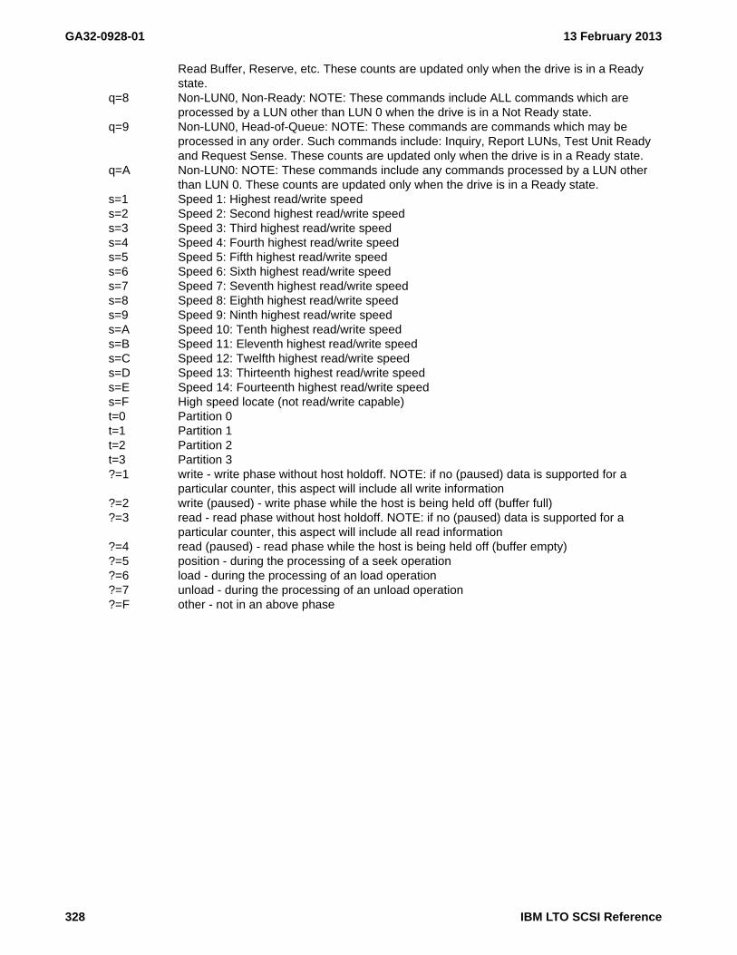
GA32-0928-01 13 February 2013
Read Buffer, Reserve, etc. These counts are updated only when the drive is in a Ready state.
q=8 Non-LUN0, Non-Ready: NOTE: These commands include ALL commands which are processed by a LUN other than LUN 0 when the drive is in a Not Ready state.
q=9 Non-LUN0, Head-of-Queue: NOTE: These commands are commands which may be processed in any order. Such commands include: Inquiry, Report LUNs, Test Unit Ready and Request Sense. These counts are updated only when the drive is in a Ready state.
q=A Non-LUN0: NOTE: These commands include any commands processed by a LUN other than LUN 0. These counts are updated only when the drive is in a Ready state.
s=1 Speed 1: Highest read/write speeds=2 Speed 2: Second highest read/write speeds=3 Speed 3: Third highest read/write speeds=4 Speed 4: Fourth highest read/write speeds=5 Speed 5: Fifth highest read/write speeds=6 Speed 6: Sixth highest read/write speeds=7 Speed 7: Seventh highest read/write speeds=8 Speed 8: Eighth highest read/write speeds=9 Speed 9: Ninth highest read/write speeds=A Speed 10: Tenth highest read/write speeds=B Speed 11: Eleventh highest read/write speeds=C Speed 12: Twelfth highest read/write speeds=D Speed 13: Thirteenth highest read/write speeds=E Speed 14: Fourteenth highest read/write speeds=F High speed locate (not read/write capable)t=0 Partition 0t=1 Partition 1t=2 Partition 2t=3 Partition 3?=1 write - write phase without host holdoff. NOTE: if no (paused) data is supported for a
particular counter, this aspect will include all write information?=2 write (paused) - write phase while the host is being held off (buffer full)?=3 read - read phase without host holdoff. NOTE: if no (paused) data is supported for a
particular counter, this aspect will include all read information?=4 read (paused) - read phase while the host is being held off (buffer empty)?=5 position - during the processing of a seek operation?=6 load - during the processing of an load operation?=7 unload - during the processing of an unload operation?=F other - not in an above phase
328 IBM LTO SCSI Reference
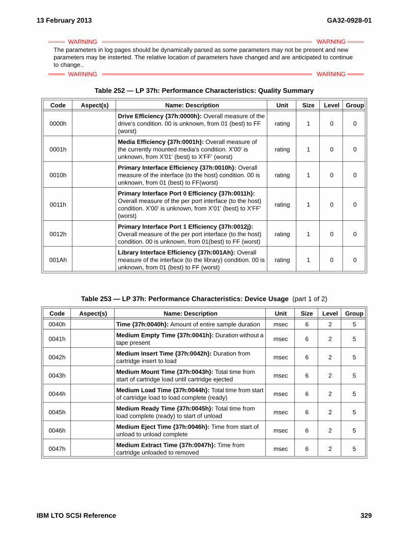
13 February 2013 GA32-0928-01
WARNING WARNINGThe parameters in log pages should be dynamically parsed as some parameters may not be present and new parameters may be insterted. The relative location of parameters have changed and are anticipated to continue
WARNING WARNING
to change..
Table 252 — LP 37h: Performance Characteristics: Quality Summary
Code Aspect(s) Name: Description Unit Size Level Group
0000hDrive Efficiency {37h:0000h}: Overall measure of the drive's condition. 00 is unknown, from 01 (best) to FF (worst)
rating 1 0 0
0001hMedia Efficiency {37h:0001h}: Overall measure of the currently mounted media's condition. X'00' is unknown, from X'01' (best) to X'FF' (worst)
rating 1 0 0
0010hPrimary Interface Efficiency {37h:0010h}: Overall measure of the interface (to the host) condition. 00 is unknown, from 01 (best) to FF(worst)
rating 1 0 0
0011h
Primary Interface Port 0 Efficiency {37h:0011h}: Overall measure of the per port interface (to the host) condition. X'00' is unknown, from X'01' (best) to X'FF' (worst)
rating 1 0 0
0012hPrimary Interface Port 1 Efficiency {37h:0012j}: Overall measure of the per port interface (to the host) condition. 00 is unknown, from 01(best) to FF (worst)
rating 1 0 0
001AhLibrary Interface Efficiency {37h:001Ah}: Overall measure of the interface (to the library) condition. 00 is unknown, from 01 (best) to FF (worst)
rating 1 0 0
Table 253 — LP 37h: Performance Characteristics: Device Usage (part 1 of 2)
Code Aspect(s) Name: Description Unit Size Level Group
0040h Time {37h:0040h}: Amount of entire sample duration msec 6 2 5
0041hMedium Empty Time {37h:0041h}: Duration without a tape present
msec 6 2 5
0042hMedium Insert Time {37h:0042h}: Duration from cartridge insert to load
msec 6 2 5
0043hMedium Mount Time {37h:0043h}: Total time from start of cartridge load until cartridge ejected
msec 6 2 5
0044hMedium Load Time {37h:0044h}: Total time from start of cartridge load to load complete (ready)
msec 6 2 5
0045hMedium Ready Time {37h:0045h}: Total time from load complete (ready) to start of unload
msec 6 2 5
0046hMedium Eject Time {37h:0046h}: Time from start of unload to unload complete
msec 6 2 5
0047hMedium Extract Time {37h:0047h}: Time from cartridge unloaded to removed
msec 6 2 5
IBM LTO SCSI Reference 329

GA32-0928-01 13 February 2013
0048h
Medium Dwell Time {37h:0048h}: Time from cartridge unloaded to (re)loaded.
Note - This may include time which cannot be determined as dwell or extract (when time is queried with a cartridge remaining in the unloaded position)
msec 6 2 5
0049hMedium Clean Time {37h:0049h}: Time from cleaner recognized to eject complete
msec 6 2 5
0051hMedium Empty Count {37h:0051h}: Number of times tape was fully removed
count 4 2 5
0052hMedium Insert Count {37h:0052h}: Number of cartridge insertions to load position detected
count 4 2 5
0053hMedium Mount Count {37h:0053h}: Number of mount operations
count 4 2 5
0054hMedium Load Count {37h:0054h}: Number of load operations
count 4 2 5
0055hMedium Ready Count {37h:0055h}: Number of ready transitions
count 4 2 5
0056hMedium Eject Count {37h:0056h}: Number of unloads
count 4 2 5
0057hMedium Extract Count {37h:0057h}: Number of times tape was extracted
count 4 2 5
0058hMedium Dwell Count {37h:0058h}: Number of times tape was reloaded (from unload)
count 4 2 5
0059hMedium Clean Count {37h:0059h}: Number of recognized cleaner loads (does not indicate successful cleans, tape may be expired)
count 4 2 5
Table 254 — LP 37h: Performance Characteristics: Host Commands (part 1 of 4)
Code Aspect(s) Name: Description Unit Size Level Group
0q00h 12(3456)789A Count {37h:0q00h}: count 4 2 1
0q01h 12(3456)789A Timing {37h:0q01h}: msec 6 2 1
0q02h 12(3456)789A Relative Time {37h:0q01h}: % * 65536 4 1 1
0q04h 12(3456)789A Transfer Count to Host (in) {37h:0q04h}: count 4 2 1
0q05h 12(3456)789A Transfer Byte Count to Host (in) {37h:0q05h}: bytes 8 2 1
0q06h 12(3456)789A Transfer Timing to Host (in) {37h:0q06h}: msec 6 2 1
0q08h 12(4)789A Transfer Count from Host (out) {37h:0q08h}: count 4 2 1
0q09h 12(4)789A Transfer Byte Count from Host (out) {37h:0q09h}: bytes 8 2 1
0q0Ah 12(4)789A Transfer Timing from Host (out) {37h:0q0Ah}: msec 6 2 1
Note - Read type host commands include Read, Verify and Read Reverse (not all of these may be supported). These counts are updated only when the drive is in a Ready state
0300hRead Count {37h:0300h}: Number of blocks processed to the host by read type commands
blocks 6 2 1
Table 253 — LP 37h: Performance Characteristics: Device Usage (part 2 of 2)
Code Aspect(s) Name: Description Unit Size Level Group
330 IBM LTO SCSI Reference

13 February 2013 GA32-0928-01
0301h
Read Timing {37h:0301h}: Amount of time processing read type commands.
Note - Due to device specific performance path resources, this may not reflect the actual time spent processing commands, but may reflect the amount of time where read commands could be processed.
msec 6 2 1
0302hRead Relative Time {37h:0302h}: Ratio of time spent reading with respect to Medium Ready Time
% * 65536 4 1 1
0304h Transfer Count to Host (in) {37h:0304h}: count 6 2 1
0305h Transfer Byte Count to Host (in) {37h:0305h}: bytes 8 2 1
0306h Transfer Timing to Host (in) {37h:0306h}: msec 6 2 1
03D0hRead Performance Efficiency {37h:03D0h}: Ratio of performance read type commands with respect to all read type commands
% * 65536 4 1 1
03D4hRead Filemark (perf) Relative Time {37h:03D4h}: Amount of time spent sending filemark encountered status to the host with respect to time Read Timing.
% * 65536 4 2 1
Note - Write type host commands include Write and Write Filemarks [not including any synchronization portion]. These counts are updated only when the drive is in a Ready state.
0400hWrite Count {37h:0400h}: Number of blocks processed from the host by write type commands
blocks 6 2 1
0401h
Write Timing {37h:0401h}: Amount of time processing write type commands.
Note - Due to device specific performance path resources, this may not reflect the actual time spent processing commands, but may reflect the amount of time where write commands could be processed.
msec 6 2 1
0402hWrite Relative Time {37h:0402h}: Ratio of time spent writing with respect to Medium Ready Time
% * 65536 4 1 1
0404h Transfer Count to Host (in) {37h:0404h}: count 6 2 1
0405h Transfer Byte Count to Host (in) {37h:0405h}: bytes 8 2 1
0406h Transfer Timing to Host (in) {37h:0406h}: msec 6 2 1
0408h Transfer Count from Host (out) {37h:0408h}: count 6 2 1
0409h Transfer Byte Count from Host (out) {37h:0409h}: bytes 8 2 1
040Ah Transfer Timing from Host (out) {37h:040Ah}: msec 6 2 1
04D0hWrite Performance Efficiency {37h:04D0h}: Ratio of performance write commands with respect to all write type commands
% * 65536 4 1 1
04D4hWrite Filemark Relative Time {37h:04D4j}: Amount of time spent writing filemarks.
% * 65536 4 2 1
Note - Sync type host commands include Write Filemarks [non-immediate]. Implicit sync type commands include mode changes while writing, non-buffered mode and idle time based syncs. These counts are updated only when the drive is in a Ready state.
0500hSync Count [Host] {37h:0500h}: Number of host sync operations (non-immediate Write Filemarks, non-buffered writes)
count 4 2 1
Table 254 — LP 37h: Performance Characteristics: Host Commands (part 2 of 4)
Code Aspect(s) Name: Description Unit Size Level Group
IBM LTO SCSI Reference 331

GA32-0928-01 13 February 2013
0501hSync Timing [Host] {37h:0501h}: Amount of time processing host sync commands
msec 6 2 1
0502hSync Relative Time [Host] {37h:0502h}: Ratio of time spent processing host sync commands with respect to Medium Ready Time
% * 65536 4 1 1
0504h Transfer Count to Host (in) {37h:0504h}: count 4 2 1
0505h Transfer Byte Count to Host (in) {37h:0505h}: bytes 8 2 1
0506h Transfer Timing to Host (in) {37h:0506h}: msec 6 2 1
05D1hSync Count [Implicit] {37h:05D1h}: Number of implicit sync commands (time based flushes, mode change flushes)
count 4 2 1
05D2hSync Timing [Implicit] {37h:05D2h}: Amount of time processing implicit sync commands
msec 6 2 1
05D4hSync Relative Time [Implicit] {37h:05D4h}: Ratio of time spent processing implicit sync commands with respect to Medium Ready Time
% * 65536 4 1 1
Note - Seek type host commands include Space, Locate, and Rewind. These counts are updated only when the drive is in a Ready state.
0600hSeek Count {37h:0600h}: Number of positioning host commands
count 4 2 1
0601hSeek Timing {37h:0601h}: Amount of time spent processing host positioning commands
msec 6 2 1
0602hSeek Relative Time {37h:0602h}: Ratio of time spend processing host seek commands with respect to Medium Ready Time
% * 65536 4 1 1
0604h Transfer Count to Host (in) {37h:0604h}: count 4 2 1
0605h Transfer Byte Count to Host (in) {37h:0605h}: bytes 8 2 1
0606h Transfer Timing to Host (in) {37h:0606h}: msec 6 2 1
06D1hSeek Block Count {37h:06D1h}: Number of blocks processed in host positioning commands
blocks 4 2 1
0Cp0h 012A Command Count {37h:0Cp0h}: count 6 2 1
0Cp1h 012A Command Timing {37h:0Cp1h}: msec 6 2 1
0Cp2h 012A Command Relative Time {37h:0Cp2h}: % * 65536 4 2 1
0Cp4h 012ACommand Transfer Count to Host (in) {37h:0Cp4h}:
count 6 2 1
0Cp5h 012ACommand Transfer Byte Count to Host (in) {37h:0Cp5h}:
bytes 8 2 1
0Cp6h 012ACommand Transfer Timing to Host (in) {37h:0Cp6h}:
msec 6 2 1
0Cp8h 012ACommand Transfer Count from Host (out) {37h:0Cp8h}:
count 6 2 1
0Cp9h 012ACommand Transfer Byte Count from Host (out) {37h:0Cp9h}:
bytes 8 2 1
0CpAh 012ACommand Transfer Timing from Host (out) {37h:0CpAh}:
msec 6 2 1
0CpCh 012A Command Queue Count {37h:0CpCh}: count 6 2 1
Table 254 — LP 37h: Performance Characteristics: Host Commands (part 3 of 4)
Code Aspect(s) Name: Description Unit Size Level Group
332 IBM LTO SCSI Reference

13 February 2013 GA32-0928-01
0CpDh 012A Command Queue Latency {37h:0CpDh}: msec 6 2 1
0CpEh 012A Command Queue Relative Time {37h:0CpEh}: % * 65536 4 2 1
0Dp1h 12APort Throughput Rate Maximum Bursting {37h:0Dp1h}:
bytes/sec 6 2 1
0Dp2h 12APort Throughput Rate Maximum Sustained {37h:0Dp2h}:
bytes/sec 6 2 1
0Dp3h 12A Port Throughput Rate {37h:0Dp3h}: bytes/sec 6 2 1
0Dp4h 12A Port Throughput Efficiency {37h:0Dp4h}: % * 65536 4 1 1
0Dp7h 12A Port Rate Changes {37h:0Dp7h}: count 4 2 1
0DF0h
Average Command Latency {37h:0DF0h}: Average amount of time commands were queued waiting for execution with respect to all commands (including unqueued commands which processed immediately).
usec 4 1 1
0DF1h
Average Dequeue Latency {37h:0DF1h}: Average amount of time commands were queued waiting for execution with respect to commands which where queued (not processed immediately).
usec 4 1 1
0DF8h Long Queue Latency Count [>1 sec] {37h:0DF8h}: count 4 2 1
0DF9h Long Queue Latency Count [>10 sec] {37h:0DF9h}: count 4 2 1
0DFAhLong Queue Latency Count [>100 sec] {37h:0DFAh}:
count 4 2 1
0DFBhLong Queue Latency Count [>1000 sec] {37h:0DFBh}:
count 4 2 1
Table 255 — LP 37h: Performance Characteristics: Host Initiators
Code Aspect(s) Name: Description Unit Size Level Group
Note - In dual port configurations it is possible for the same host to be identified as a different initiator when using a different logical or physical path. This can occur in failover or load balancing applications.
0E00hActive Initiator Count {37h:0E00h}: Number of initiators which processed one or more commands.
count 4 2 1
0E01hPrimary Initiator {37h:0E01h}: Ratio of commands issued by the initiator which is issuing the most commands with respect to all initiators.
% * 65536 4 2 1
0E02hSecondary Initiator {37h:0E02h}: Ratio of commands issued by the initiator which is issuing the second most commands with respect to all initiators.
% * 65536 4 2 1
0E03hCurrent Initiator {37h:0E03h}: Ratio of commands issued by this (the querying) initiator with respect to all initiators.
% * 65536 4 2 1
Table 254 — LP 37h: Performance Characteristics: Host Commands (part 4 of 4)
Code Aspect(s) Name: Description Unit Size Level Group
IBM LTO SCSI Reference 333

GA32-0928-01 13 February 2013
Table 256 — LP 37h: Performance Characteristics: Host Recovery (by port)
Code Aspect(s) Name: Description Unit Size Level Group
0Fp0h 12A Transfer Recoveries [by port] {37h:0Fp0h}: count 4 2 1
0Fp1h 12A Transfer Recover Time [by port] {37h:0Fp1h}: msec 6 2 1
0Fp2h 12A Resource Recoveries [by port] {37h:0Fp2h}: count 4 2 1
0Fp3h 12A Reset Count [by port] {37h:0Fp3h}: count 4 2 1
0Fp8h 12A Abort Count [by port] {37h:0Fp8h}: count 4 2 1
0Fp9h 12A Abort Time [by port] {37h:0Fp9h}: msec 6 2 1
Table 257 — LP 37h: Performance Characteristics: Mode Phase Timing Windows (part 1 of 3)
Code Aspect(s) Name: Description Unit Size Level Group
1000h Write Cycles {37h:1000h}: count 4 2 2
1001h Write Pauses {37h:1001h}: count 4 2 2
1010h Write Cycle Time {37h:1010h}: msec 6 2 2
1020hWrite Cycle Relative Time {37h:1020h}: Ratio of time in write mode with respect to Medium Ready Time.
% * 65536 4 1 2
1021h Write Setup Relative Time {37h:1021h}: % * 65536 4 2 2
1022h Write Ready Relative Time {37h:1022h}: % * 65536 4 1 2
1023h Write Pause Relative Time {37h:1023h}: % * 65536 4 1 2
1024h Write Exit Relative Time {37h:1024h}: % * 65536 4 2 2
1200h Read Cycles {37h:1200h}: count 4 2 2
1201h Read Pauses {37h:1201h}: count 4 2 2
1210h Read Cycle Time {37h:1210h}: msec 6 2 2
1220hRead Cycle Relative Time {37h:1220h}: Ratio of time in write mode with respect to Medium Ready Time.
% * 65536 4 1 2
1221h Read Setup Relative Time {37h:1221h}: % * 65536 4 2 2
1222h Read Ready Relative Time {37h:1222h}: % * 65536 4 1 2
1223h Read Pause Relative Time {37h:1223h}: % * 65536 4 1 2
1224h Read Exit Relative Time {37h:1224h}: % * 65536 4 2 2
1225h Read Traverse EM Relative Time {37h:1225h}: % * 65536 4 2 2
1400h Position Count {37h:1400h}: count 4 2 2
1410h Position Time {37h:1410h}: msec 6 2 2
1420hPosition Relative Time {37h:1420h}: Ratio of time spent physically and logically positioning with respect to Medium Ready Time.
% * 65536 4 1 2
1430h Position Relative Rate {37h:1430h}: bytes/sec 4 1 2
1480h Position Count (Media) {37h:1480h}: count 4 2 2
1490h Position Time (Media) {37h:1490h}: msec 6 2 2
14A0hPosition Relative Time (Media) {37h:14A0h}: Ratio of time spent physically positioning media with respect to Medium Ready Time.
% * 65536 4 1 2
14B0h Position Relative Rate (Media) {37h:14B0h}: bytes/sec 4 1 2
334 IBM LTO SCSI Reference

13 February 2013 GA32-0928-01
14F0hPosition Buffer Hits {37h:14F0h}: Ratio of positioning operations where targets were already present in the buffer.
% * 65536 4 1 2
1500h
Flush Count {37h:1500h}: Number of low level buffer write flush operations. These may include operations which only affect the buffer and do not involve media motion.
count 4 1 2
1510hFlush Time {37h:1510h}: Time spend executing operations counted by Flush Count.
msec 6 2 2
1520hFlush Relative Time {37h:1520h}: Ratio of time spent flushing with respect to Medium Ready Time.
% * 65536 4 1 2
1580hFlush Count (Media) {37h:1580h}: Number of low level buffer write flush operations which involve [or continue] media motion.
count 4 1 2
1590hFlush Time (Media) {37h:1590h}: Time spent executing operations counted by Flush Count (Media).
msec 6 2 2
15A0hFlush Relative Time (Media) {37h:15A0h}: Ratio of time spent flushing to media with respect to Write Cycle Time.
% * 65536 4 1 2
15F0hFlush Buffer Hits {37h:15F0h}: Ratio of flush operations which required media motion.
% * 65536 4 1 2
2000h Media Idle {37h:2000h}: msec 6 2 3
2001h Media Write {37h:2001h}: msec 6 2 3
2002h Media Read {37h:2002h}: msec 6 2 3
2003h Media Erase {37h:2003h}: msec 6 2 3
2004h Media Position {37h:2004h}: msec 6 2 3
20?0h 1234567F Media Phase Timing {37h:20?0h}: msec 6 2 3
20?1h 1234567F Media Phase Cycles {37h:20?1h}: count 4 2 3
2?10h 1234567FWrap Change Count {37h:2?10h}: Total number of wrap changes.
count 4 2 3
2?11h 1234567FBand Change Count {37h:2?11h}: Total number of changes to different servo bands.
count 4 2 3
2?50h 13Datarate Performance Impacting ERPs {37h:2?50h}:
% * 65536 4 1 3
2?51h 13567F Performance Impacting ERPs {37h:2?51h}: % * 65536 4 1 3
2?52h 1234567F Performance Impact by ERPs {37h:2?52h}: % * 65536 4 1 3
2?60h 135 Uncompressed Data {37h:2?60h}: bytes 8 2 2
2?61h 135 Compressed Data {37h:2?61h}: bytes 8 2 2
2?62h 135 Padded Data {37h:2?62h}: bytes 8 2 2
2?63h 135 Degate Data {37h:2?63h}: bytes 8 2 2
2?68h 135 Datasets Processed {37h:2?68h}: datasets 4 2 2
2?6Ch 13 Compression Ratio {37h:2?6Ch}: % * 65536 4 1 2
2?71h 13F Compressed Data (Medium) {37h:2?71h}: bytes 8 2 3
2?72h 13F Padded Data (Medium) {37h:2?72h}: bytes 8 2 3
2?80h 13 Maximum Host Transfer Rate {37h:2?80h}: bytes/sec 4 1 2
Table 257 — LP 37h: Performance Characteristics: Mode Phase Timing Windows (part 2 of 3)
Code Aspect(s) Name: Description Unit Size Level Group
IBM LTO SCSI Reference 335

GA32-0928-01 13 February 2013
2?81h 13 Average Host Transfer Rate {37h:2?81h}: bytes/sec 4 1 2
2?82h 13 Average Host Buffer Rate {37h:2?82h}: bytes/sec 4 1 2
2?83h 13 Window Host Buffer Rate {37h:2?83h}: bytes/sec 4 1 2
2?84h 13 Host Buffer Efficiency {37h:2?84h}: % * 65536 4 1 2
2?85h 13 Window Buffer Efficiency {37h:2?85h}: % * 65536 4 1 2
2?88h 13 Average Host Transfer Length {37h:2?88h}: bytes 4 2 2
2?8Ch 1 Average Host Sync Length {37h:2?8Ch}: bytes 6 2 2
2?90h 13 Maximum Comp Transfer Rate {37h:2?90h}: bytes/sec 4 1 2
2?91h 13 Average Comp Transfer Rate {37h:2?91h}: bytes/sec 4 1 2
2?92h 13 Average Comp Buffer Rate {37h:2?92h}: bytes/sec 4 1 2
2?93h 13 Window Comp Buffer Rate {37h:2?93h}: bytes/sec 4 1 2
2?94h 13 Comp Buffer Efficiency {37h:2?94h}: % * 65536 4 1 2
2?95h 13 Window Comp Buffer Efficiency {37h:2?95h}: % * 65536 4 1 2
2?98h 13 Average Comp Transfer Length {37h:2?98h}: bytes 4 2 2
2?9Ch 1 Average Comp Sync Length {37h:2?9Ch}: bytes 6 2 2
2?A0h 13 Maximum Tape Transfer Rate {37h:2?A0h}: bytes/sec 4 1 2
2?A1h 13 Average Tape Buffer Rate {37h:2?A1h}: bytes/sec 4 2 2
2?A2h 13 Window Tape Buffer Rate {37h:2?A2h}: bytes/sec 4 2 2
2?A3h 13 Moving Tape Buffer Rate {37h:2?A3h}: bytes/sec 4 2 2
2?A4h 13 Window Tape Buffer Efficiency {37h:2?A4h}: % * 65536 4 2 2
2?A5h 13 Moving Tape Buffer Efficiency {37h:2?A5h}: % * 65536 4 2 2
2?A6h 13
Tape Buffer Efficiency {37h:2?A6h}: Ratio of amount of time we are usefully moving and ready with respect to amount of time the buffer is able to process data. A ratio larger than 1 indicates the compressed host data is arriving faster than the native device rate. Lower values indicate the device has under utilized host bandwidth.
% * 65536 4 2 2
2?A7h 13FTape Thrashing {37h:2?A7h}: Ratio of amount of time we are accelerating, decelerating or backhitching with respect to the time in mode.
% * 65536 4 2 2
2?A8h 13FTape Efficiency {37h:2?A8h}: Ratio of amount of time we are usefully moving and ready with respect to the time in mode.
% * 65536 4 1 2
2?F0h 13 Speed Changes {37h:2?F0h}: count 4 2 2
2?F1h 13 Speed Forced {37h:2?F1h}: count 4 2 2
Table 258 — LP 37h: Performance Characteristics: Servo Speed Characteristics
Code Aspect(s) Name: Description Unit Size Level Group
5Fs0h 123456789ABCDEF Servo Speed Relative Time {37h:5Fs0h}: % * 65536 4 2 6
Table 257 — LP 37h: Performance Characteristics: Mode Phase Timing Windows (part 3 of 3)
Code Aspect(s) Name: Description Unit Size Level Group
336 IBM LTO SCSI Reference

13 February 2013 GA32-0928-01
Table 259 — LP 37h: Performance Characteristics: Static Capacity
Code Aspect(s) Name: Description Unit Size Level Group
7000h Static Capacity Efficiency {37h:7000h}: % * 65536 4 1 4
7010h Static Datasets Media {37h:7010h}: datasets 4 2 4
7011h Static Datasets Used {37h:7011h}: datasets 4 2 4
7020h Static Distance Media {37h:7020h}: mm 8 2 4
7021h Static Distance Used {37h:7021h}: mm 8 2 4
7030hStatic Remaining Capacity in SkipSync Buffer {37h:7030h}:
% * 65536 4 2 4
Table 260 — LP 37h: Performance Characteristics: Active Capacity
Code Aspect(s) Name: Description Unit Size Level Group
7?00h 13F Active Capacity Efficiency {37h:7?00h}: % * 65536 4 1 4
7?10h 13F Active Sync Loss {37h:7?10h}: % * 65536 4 2 4
7?11h 13F Active Skip Loss {37h:7?11h}: % * 65536 4 2 4
7?12h 13F Active DSS Loss {37h:7?12h}: % * 65536 4 2 4
7?13h 13F Active CQs Loss (on-the-fly) {37h:7?13h}: % * 65536 4 2 4
7?21h 13F Active Distance Skip {37h:7?21h}: mm 8 2 4
7?22h 13F Active Distance DSS {37h:7?22h}: mm 8 2 4
7?23h 13F Active Distance CQs (on-the-fly) {37h:7?23h}: mm 8 2 4
7?2Fh 13F Active Distance Total {37h:7?2Fh}: mm 8 2 4
Table 261 — Log Page 37h: Performance Characteristics: Static Capacity per Partition
Code Aspect(s) Name: Description Unit Size Level Group
8t00h 01 Static Capacity Efficiency (Partition t) {37h:8t00h}: % * 65536 4 1 4
8t10h 01 Static Datasets Media (Partition t) {37h:8t10h}: datasets 4 2 4
8t11h 01 Static Datasets Used (Partition t) {37h:8t11h}: datasets 4 2 4
8t20h 01 Static Distance Media (Partition t) {37h:8t20h}: mm 8 2 4
8t21h 01 Static Distance Used (Partition t) {37h:8t21h}: mm 8 2 4
IBM LTO SCSI Reference 337

GA32-0928-01 13 February 2013
6.4.23 LP 38h: Blocks/Bytes Transferred
See LOG SELECT - 4Ch (see 5.2.7 on page 87) and LOG SENSE - 4Dh (see 5.2.8 on page 88) for directions on how to use this page.
6.4.23.1 Parameter Reset Behavior (38h)
Parameters in this page are reset when a cartridge is loaded.
6.4.23.2 Parameter Definitions (38h)
WARNING WARNINGThe parameters in log pages should be dynamically parsed as some parameters may not be present and new parameters may be insterted. The relative location of parameters have changed and are anticipated to continue
WARNING WARNING
to change..
Table 262 — LP 38h: Blocks/Bytes Transferred log parameter codes (part 1 of 2)
Code Counter: Description Size
0000hHost Write Blocks Processed {38h:0000h}: Each count represents a block processed across the host interface during a Write. The count does not include ERP retries.
4
0001h
Host Write Kebibytes Processed {38h:0001h}: Each count represents a kebibyte (1024 bytes) processed across the host interface during a Write. The count does not include ERP retries. This count may be divided by Device Write Kebibytes Processed, 0005, to calculate an approximate write compression ratio.
4
0002hHost Read Blocks Processed {38h:0002h}: Each count represents a block processed across the host interface during a Read. The count does not include ERP retries.
4
0003h
Host Read Kebibytes Processed {38h:0003h}: Each count represents a kebibyte (1024 bytes) processed across the host interface during a Read. The count does not include ERP retries. This count may be divided by Device Read Kebibytes Processed, 0007, to calculate an approximate read compression ratio.
4
0004hDevice Write Datasets Processed {38h:0004h}: Each count represents a dataset processed on the medium. The count does not include ERP retries.
4
0005hDevice Write Kebibytes Processed {38h:0005h}: Each count represents a kebibyte (1024 bytes) processed on the medium. The count does not include ERP retries or any tape formatting overhead bytes.
4
0006hDevice Read Datasets Processed {38h:0006h}: Each count represents a dataset processed from the medium. The count does not include ERP retries.
4
0007hDevice Read Kebibytes Processed {38h:0007h}: Each count represents a kebibyte (1024 bytes) processed from the medium. The count does not include ERP retries or any tape formatting overhead bytes.
4
0008hDevice Write Datasets Transferred {38h:0008h}: Each count represents a dataset processed on the medium. The count includes ERP retries.
4
0009hDevice Write Kebibytes Transferred {38h:0009h}: Each count represents a kebibyte (1024 bytes) processed on the medium. The count includes ERP retries and any tape formatting overhead bytes.
4
000AhDevice Read Datasets Transferred {38h:000Ah}: Each count represents a dataset processed from the medium. The count includes ERP retries.
4
000BhDevice Read Kebibytes Transferred {38h:000Bh}: Each count represents a kebibyte (1024 bytes) processed from the medium. The count includes ERP retries and any tape formatting overhead bytes.
4
000ChNominal Capacity of Partition {38h:000Ch}: The nominal capacity of the current partition (in kebibytes).
4
338 IBM LTO SCSI Reference

13 February 2013 GA32-0928-01
000DhFraction of Partition Traversed {38h:000Dh}: The fractional part of the current partition traversed (N/255).
1
000EhNominal Capacity of Volume {38h:000Eh}: The nominal capacity of the mounted volume (in kebibytes). This is determined by the sum of the Nominal Capacity of Partition parameter for each partition.
4
000FhFraction of Volume Traversed {38h:000Fh}: The fractional part of the mounted volume traversed (N/255). This reports the value that would be reported by the Fraction of Partition Traversed if the volume were a single partition.
1
0010h
Remaining Capacity of Volume {38h:0010h}: The nominal unwritten remaining capacity of the mounted volume (in kebibytes). This is not sensitive to current position. This is determined by the sum of the Remaining Capacity of Partition for each partition.If the tape does not have a valid EOD in at least one existing partition, or if a tape is not loaded, then a value of ’all ones’ (-1) is returned.
4
0011h
Remaining Capacity of Partition {38h:0011h}: The nominal unwritten remaining capacity of the current partition (in kebibytes). This is not sensitive to current position.If the tape does not have a valid EOD in the current partition, or if a tape is not loaded, then a value of ’all ones’ (-1) is returned.
4
Table 262 — LP 38h: Blocks/Bytes Transferred log parameter codes (part 2 of 2)
Code Counter: Description Size
IBM LTO SCSI Reference 339

GA32-0928-01 13 February 2013
6.4.24 LP 39h: Host Port 0 Interface Errors
See LOG SELECT - 4Ch (see 5.2.7 on page 87) and LOG SENSE - 4Dh (see 5.2.8 on page 88) for directions on how to use this page. The count of errors occurring on host interface port 0 (while the device is active on the interface).
6.4.24.1 Parameter Reset Behavior (39h)
Parameters in this page are reset when a cartridge is loaded.
6.4.24.2 Parameter Definitions (39h)
WARNING WARNINGThe parameters in log pages should be dynamically parsed as some parameters may not be present and new parameters may be insterted. The relative location of parameters have changed and are anticipated to continue
WARNING WARNING
to change..
Table 263 — LP 39h: Host Port Interface Errors log parameter codes
Code Counter: Description Size
0000h
Host Protocol Errors {39h:000h}: Each count represents one occurrence. Counts may include occurrences from both temporary and permanent errors. (On SAS attached devices, this parameter is always set to zero. See LP 18h: Protocol-specific port (see 6.4.13 on page 308) for SAS protocol error counts).
2
0007hHost Aborts {39h:0007h}: Each count represents one occurrence. Counts may include occurrences from both temporary and permanent errors.
2
0008hHost Resets {39h:0008h}: Each count represents one occurrence. Counts may include occurrences from both temporary and permanent errors.
2
0009h Vendor-Reserved 2
000Ah Vendor-Reserved 2
0010h
Host Recoveries {39h:0010h}: Each count represents one occurrence. Counts may include occurrences from both temporary and permanent errors. An example of a host recoveries is a Fibre Channel Sequence Retransmission Request (SRR). On SAS attached devices, this parameter is the count of TLR’s.
4
340 IBM LTO SCSI Reference

13 February 2013 GA32-0928-01
6.4.25 LP 3Ah: Drive control verification
See LOG SELECT - 4Ch (see 5.2.7 on page 87) and LOG SENSE - 4Dh (see 5.2.8 on page 88) for directions on how to use this page. This page is for special drive control mode verification. This page is not included in the list of supported pages (page code 00h) and is not intended for general use. This page is not shown in this document.
IBM LTO SCSI Reference 341

GA32-0928-01 13 February 2013
6.4.26 LP 3Bh: Host Port 1 Interface Errors
See LOG SELECT - 4Ch (see 5.2.7 on page 87) and LOG SENSE - 4Dh (see 5.2.8 on page 88) for directions on how to use this page. The count of errors occurring on host port 1 (while the device is active on the interface).
6.4.26.1 Parameter Reset Behavior (3Bh)
Parameters in this page are reset when a cartridge is loaded.
6.4.26.2 Parameter Definitions (3Bh)
NOTE 42 - The parameters are identical to those found in LP 39h: Host Port 0 Interface Errors (see 6.4.24 on page 340), except this data is recorded for incidents which occur on host interface port 1.
WARNING WARNINGThe parameters in log pages should be dynamically parsed as some parameters may not be present and new parameters may be insterted. The relative location of parameters have changed and are anticipated to continue
WARNING WARNING
to change.
342 IBM LTO SCSI Reference

13 February 2013 GA32-0928-01
6.4.27 LP 3Ch: Drive usage information
See LOG SELECT - 4Ch (see 5.2.7 on page 87) and LOG SENSE - 4Dh (see 5.2.8 on page 88) for directions on how to use this page. The Drive usage information log page only has valid data returned when the drive is configured for use in an eServer® system (i.e., The Product ID returned in Standard Inquiry is "HH LTO Gen x" where "x" is a number).
This page allows users to obtain the information last stored regarding the counts accumulated over the life of the drive.
6.4.27.1 Parameter Reset Behavior (3Ch)
This page is updated as events and tape pulling occurs. The nonvolatile memory is updated upon error events, the tape being unthreaded, or when the cartridge unloads. The counters are not cleared by any reset and cannot be changed with the LOG SELECT command. If power is lost before the updated data is written to the nonvolatile memory, the counts are not updated.
6.4.27.2 Parameter Definitions (3Ch)
Each parameter is a positive value. The counts do not overflow. Once a count reaches its maximum value, that maximum value is always returned. The counts do not roll over at the maximum value.
WARNING WARNINGThe parameters in log pages should be dynamically parsed as some parameters may not be present and new parameters may be insterted. The relative location of parameters have changed and are anticipated to continue
WARNING WARNING
to change.
Table 264 — LP 3Ch: Drive usage information log parameters (part 1 of 2)
ParameterCode
Counter: Description Size
0001h
Write Media Blocks Counter {3Ch:0001h}: This counter is a lifetime statistic representing the number of physical groups (i.e. Datasets) written during a write operation. Upon reaching the maximum value, the counter does not wrap back to zero, but retains its maximum value (FFFF FFFF FFFF FFFFh).
8
0002h
Rewrite Media Blocks Counter {3Ch:0002h}: This counter is a lifetime statistic representing the number of physical groups (i.e. Datasets) rewritten during a write operation. Upon reaching the maximum value, the counter does not wrap back to zero, but retains its maximum value (FFFF FFFF FFFF FFFFh).
8
0003h
Read Media Blocks Counter {3Ch:0003h}: This counter is a lifetime statistic representing the number of physical groups (i.e. Datasets) read during a read or space operation. The counter will not increment/decrement during space reverse, space LEOP, or space fast operations. Upon reaching the maximum value, the counter does not wrap back to zero, but retains its maximum value (FFFF FFFF FFFF FFFFh).
8
0004h
ECC Corrections Counter {3Ch:0004h}: This counter is a lifetime statistic representing the number of physical groups (i.e. Datasets) corrected during a read operation. Upon reaching the maximum value, the counter does not wrap back to zero, but retains its maximum value (FFFF FFFF FFFF FFFFh).
8
0005h
Reread Media Blocks Counter {3Ch:0005h}: This counter is a lifetime statistic representing the number of physical groups (i.e. Datasets) reread during a read operation. Upon reaching the maximum value, the counter does not wrap back to zero, but retains its maximum value (FFFF FFFF FFFF FFFFh).
8
0006h
Cumulative Cartridge Loads Counter {3Ch:0006h}: This counter increments each time a new cartridge is loaded. All media types and lengths increments this counter. Cleaning cartridges do not increment the counter. Upon reaching the maximum value, the counter does not wrap back to zero, but retains its maximum value (FF FFFFh).
3
IBM LTO SCSI Reference 343

GA32-0928-01 13 February 2013
0007h
Time Since Last Cleaning Counter {3Ch:0007h}: This counter tracks the tape pulling time since the last cleaning. The count is expressed in minutes. Upon reaching the maximum value, the counter does not wrap back to zero, but retains its maximum value (FF FFFFh). The counter is reset when the drive is cleaned.
3
0008hCumulative Power On Time Counter {3Ch:0008h}: This is a cumulative count of the time the drive has been powered on. The count is expressed in minutes. Upon reaching the maximum value, the counter does not wrap back to zero, but retains its maximum value (FF FFFFh).
3
0009hCumulative Time Tape is Loaded and Tensioned {3Ch:0009h}: This is the number of minutes a tape has been threaded with tension on the tape.
3
000AhCumulative Cleaning Counter {3Ch:000Ah}: This is the count of the number of times that a cleaning cartridge was inserted into the drive. Upon reaching the maximum value, the counter does not wrap back to zero, but retains its maximum value (FFFFh).
2
000Bh
"WORN MEDIA" Flag {3Ch:000Bh}: This flag is used by the drive to recommend retirement of the current cartridge. This flag is set when the condition is detected (e.g. on rewind, processing of Log Sense). This flag is cleared on next cartridge load. This corresponds to TapeAlert Flag 07h. 0001h: Media should be retired.0000h: Media is still good enough to use or media condition cannot be determined (e.g. No media loaded).
2
000Ch
"DEAD MEDIA" Flag {3Ch:000Ch}: This flag is used by the drive to indicate the media is no longer usable. This flag is set when the condition is detected and an error is reported. This flag is cleared on next cartridge load. This corresponds to TapeAlert flag 04h, and the posting of a "DEGRADED MEDIA" message (k/c/q '01/82/52').0001h: Media is no longer usable.0000h: Media is still usable or media condition cannot be determined (e.g. No media loaded).
2
000Dh
"DEAD DRIVE" Flag {3Ch:000Dh}: This flag is used by the drive to recommend its own replacement. This flag is set when the condition is detected and an error is reported. This flag is never cleared once set.0001h: Drive hardware failure has occurred or is imminent. Replace drive.0000h: Drive hardware failure has not been detected. No drive replacement required.
2
000Eh Undefined Parameter (0000h) 2
000Fh Undefined Parameter (0000h) 2
0010h Undefined Parameter (0000h) 2
0011hClean Requested Flag {3Ch:0011h}: This flag indicates the drive should be cleaned.02h: Drive is not requesting clean03h: Drive is requesting clean
1
0012h Undefined Parameter (00h) 1
0013h Undefined Parameter (00 0000h) 3
0014h Undefined Parameter (00 0000h) 3
0015hCartridge Serial Number {3Ch:0015h}: This is right justified with leading spaces (20h). This value is update on cartridge load and retained until the next cartridge load. If no cartridge has been loaded since last power-on this value will be set to all spaces (20h).
12
Table 264 — LP 3Ch: Drive usage information log parameters (part 2 of 2)
ParameterCode
Counter: Description Size
344 IBM LTO SCSI Reference

13 February 2013 GA32-0928-01
6.4.28 LP 3Dh: Subsystem Statistics
See LOG SELECT - 4Ch (see 5.2.7 on page 87) and LOG SENSE - 4Dh (see 5.2.8 on page 88) for directions on how to use this page. The following counters all deal with subsystem statistics and errors.
6.4.28.1 Parameter Reset Behavior (3Dh)
Most of the counters on this page are never reset. Most counters are maintained in VPD and persist across Log Select, Log Sense, Power On Resets, and even microcode download. Lifetime values are written to VPD every eight operating hours when the drive is in a not ready state. The counters lock at maximum values.
6.4.28.2 Parameter Definitions (3Dh)
WARNING WARNINGThe parameters in log pages should be dynamically parsed as some parameters may not be present and new parameters may be insterted. The relative location of parameters have changed and are anticipated to continue
WARNING WARNING
to change..
Table 265 — LP 3Dh: Subsystem Statistics log parameter codes (part 1 of 2)
Code Counter: Description Size
0020hVolume Lifetime Mounts {3Dh:0020h}: The total number of successful cartridge unloads performed during the lifetime of a cartridge. This field may not be updated for mounts that occur with the volume physically write-protected.
4
0021h
Volume Lifetime Megabytes Written {3Dh:0021h}: The total amount of data in Megabytes (106) written during the lifetime of the cartridge. On each unload, an approximate value is calculated and stored by rounding up to the nearest Megabyte. These bytes are counted as they are processed to the medium (compressed bytes), not at the host interface. This field may not be updated during mounts that occur with the volume physically write-protected.
4
0022h
Volume Lifetime Megabytes Read {3Dh:0022h}: The total amount of data in Megabytes (106) read during the lifetime of the cartridge. On each unload, an approximate value is calculated and stored by rounding up to the nearest Megabyte. These bytes are counted as they are processed from the medium (compressed bytes), not at the host interface. This field may not be updated during mounts that occur with the volume physically write-protected.
4
0040hDrive Lifetime Mounts {3Dh:0040h}: The total number of successful cartridge unloads performed during the lifetime of the drive.
4
0041h
Drive Lifetime Megabytes Written {3Dh:0041h}: The total amount of data in Megabytes (106) written during the lifetime of the drive. On each unload, an approximate value is calculated and stored by rounding up to the nearest Megabyte. These bytes are counted as they are processed to the medium (compressed bytes), not at the host interface.
4
0042h
Drive Lifetime Megabytes Read {3Dh:0042h}: The total amount of data in Megabytes (106) read during the lifetime of the drive. On each unload, an approximate value is calculated and stored by rounding up to the nearest Megabyte. These bytes are counted as they are processed from the medium (compressed bytes), not at the host interface.
4
0060hClean Lifetime Mounts {3Dh:0060h}: The total number of successful cleaner cartridge operations performed during the lifetime of the drive.
4
0061h
Megabytes Written since Clean {3Dh:0061h}: The total amount of data in Megabytes (106) written since the last successful clean operation. On each unload, an approximate value is calculated and stored by rounding up to the nearest Megabyte. These bytes are counted as they are processed to the medium (compressed bytes), not at the host interface.
4
0062h
Megabytes Read since Clean {3Dh:0062h}: The total amount of data in Megabytes (106) read since the last successful clean operation. On each unload, an approximate value is calculated and stored by rounding up to the nearest Megabyte. These bytes are counted as they are processed from the medium (compressed bytes), not at the host interface.
4
IBM LTO SCSI Reference 345

GA32-0928-01 13 February 2013
0063hMounts since Clean {3Dh:0063h}: The total number of mounts performed since the last successful clean operation.
4
0080hLibrary Interface Messages Received {3Dh:0080h}: This counter is not stored in VPD and reflects messages since reset.
4
0081hLibrary Interface Messages Transmitted {3Dh:0081h}: This counter is not stored in VPD and reflects message since reset.
4
0082hLibrary Interface Resets {3Dh:0082h}: Count of hardware reset or logical reinitializations during normal operation.
4
0083hLibrary Interface Buffer Errors {3Dh:0083h}: This includes buffer overrun or underrun conditions.
4
0084h Library Interface Sync Errors {3Dh:0084h}: 4
0085h Library Interface Framing Errors {3Dh:0085h}: 4
0086h Library Interface Protocol Errors {3Dh:0086h}: 4
0087h Library Interface Logical Errors {3Dh:0087h}: 4
0088hLibrary Interface Loader Failures {3Dh:0088h}: This counter reflects load attempts when the drive is in an incorrect state or was otherwise unable to attempt requested loader action.
4
0090hDrive Lifetime Write Perms {3Dh:0090h}: Total number of write permanent errors which occurred on this drive.
4
0091hDrive Lifetime Read Perms {3Dh:0091h}: Total number of read permanent errors which occurred on this drive.
4
0092hDrive Lifetime Load Perms {3Dh:0092h}: Total number of load permanent errors which occurred on this drive.
4
0093hDrive Lifetime Unload Perms {3Dh:0093h}: Total number of unload permanent errors which occurred on this drive.
4
00A0h
Drive Lifetime Write Temps {3Dh:00A0h}: Total number of write temporary errors which occurred on this drive.
Note - This is not a count of ERP actions taken, and certain transient errors may not be included in this count.
4
00A1h
Drive Lifetime Read Temps {3Dh:00A1h}: Total number of read temporary errors which occurred on this drive.
Note - This is not a count of ERP actions taken, and certain transient errors may not be included in this count.
4
00A2h
Drive Lifetime Load Temps {3Dh:00A2h}: Total number of load temporary errors which occurred on this drive.
Note - This is not a count of ERP actions taken, and certain transient errors may not be included in this count.
4
00A3h
Drive Lifetime Unload Temps {3Dh:00A3h}: Total number of unload temporary errors which occurred on this drive.
Note - This is not a count of ERP actions taken, and certain transient errors may not be included in this count.
4
0100h
Lifetime Power On Seconds {3Dh:0100h}: Cumulative number of seconds which the drive has been powered on.
Note - Since this time is only periodically updated in non-volatile storage, it is possible that this time may not be entirely accurate to the full resolution of the counter.
4
0101hPower On Seconds {3Dh:0101h}: Number of seconds since the drive was powered on or has undergone a hard reset condition.
4
0102hReset Seconds {3Dh:0102h}: Number of seconds since the drive has undergone a soft reset condition.
4
Table 265 — LP 3Dh: Subsystem Statistics log parameter codes (part 2 of 2)
Code Counter: Description Size
346 IBM LTO SCSI Reference

13 February 2013 GA32-0928-01
6.4.29 LP 3Eh: Engineering Use
See LOG SELECT - 4Ch (see 5.2.7 on page 87) and LOG SENSE - 4Dh (see 5.2.8 on page 88) for directions on how to use this page. This page is for engineering use only and is not included in the list of supported pages (i.e., page code 00h). As such, the counters on this page are not intended for general use and are not shown in this document.
IBM LTO SCSI Reference 347

GA32-0928-01 13 February 2013
6.4.30 LP 3Eh[3Ch]: Drive Control Statistics
See LOG SELECT - 4Ch (see 5.2.7 on page 87) and LOG SENSE - 4Dh (see 5.2.8 on page 88) for directions on how to use this page. This page is for special drive control mode statistics. It is not included in the list of supported pages (page code 00h) and is not intended for general use. This page is not shown in this document.
NOTE 43 - This page was log page 3Ch in Ultrium 2, but was moved to log page 3E[3C] for Ultrium 2 HH and newer generations (eServer support with it’s log page 3C was added).
348 IBM LTO SCSI Reference

13 February 2013 GA32-0928-01
6.5 Medium auxiliary memory attributes (MAM)
6.5.1 Attribute format
Each medium auxiliary memory attribute shall be communicated between the application client and device server in the format shown in table 266. This format shall be used in the parameter data for the WRITE ATTRIBUTE command (see 5.2.39) and the READ ATTRIBUTE command (see 5.2.13). The attribute format in this standard implies nothing about the physical representation of an attribute in the medium auxiliary memory.
The ATTRIBUTE IDENTIFIER field contains a code value identifying the attribute (see 6.5.2).
The READ ONLY bit indicates whether the attribute is in the read only state (see 4.17). If the READ ONLY bit is set to one, the attribute is in the read only state. If the READ ONLY bit is set to zero, the attribute is in the read/write state.
The FORMAT field (see table 267) specifies the format of the data in the ATTRIBUTE VALUE field.
The ATTRIBUTE LENGTH field specifies the length in bytes of the ATTRIBUTE VALUE field.
The ATTRIBUTE VALUE field contains the current value, for the READ ATTRIBUTE - 8Ch (see 5.2.15 on page 104) command, or intended value, for the WRITE ATTRIBUTE - 8Dh (see 5.2.39 on page 175) command, of the attribute.
Table 266 — MAM ATTRIBUTE format
ByteBit
7 msb 6 5 4 3 2 1 0 lsb
0 (MSB)attribute identifier
1 (LSB)
2 READ ONLY Reserved FORMAT
3 (MSB)ATTRIBUTE LENGTH (n-4)
4 (LSB)
5attribute value
n
Table 267 — MAM attribute FORMAT field
Format Name Description
00b BINARY The ATTRIBUTE VALUE field contains binary data.
01b ASCII The ATTRIBUTE VALUE field contains left-aligned ASCII data.
10b TEXTThe attribute contains textual data. The character set is as described in the TEXT LOCALIZATION IDENTIFIER attribute (see 6.5.2.4.6).
11b Reserved
IBM LTO SCSI Reference 349

GA32-0928-01 13 February 2013
6.5.2 Attribute identifier values
6.5.2.1 Attribute identifier values overview
The values in the ATTRIBUTE IDENTIFIER field (see 6.5.1) are assigned according to the attribute type (see 4.17) and whether the attribute is standard or vendor specific (see table 268).
Device servers may accept and process a WRITE ATTRIBUTE command containing standardized host type attribute identifier values (i.e., 0800h-0BFFh) or vendor specific host type attribute identifier values (i.e., 1400h-17FFh). Standardized host type attribute identifier values may be checked as described in 6.5.2.4.
6.5.2.2 Device type attributes
Device type attributes (see table 269) shall be maintained and updated by the device server when the medium and associated medium auxiliary memory are present. All supported medium type attributes shall have a status
Table 268 — MAM attribute identifier range assignments
Attribute Identifiers Attribute Type Standardized Subclause
0000h to 03FFh Device Yes 6.5.2.2
0400h to 07FFh Medium Yes 6.5.2.3
0800h to 0BFFh Host Yes 6.5.2.4
0C00h to 0FFFh Device Vendor specific
1000h to 13FFh Medium Vendor specific
1400h to 17FFh Host Vendor specific
1800h to FFFFh Reserved
350 IBM LTO SCSI Reference

13 February 2013 GA32-0928-01
of read only (see 4.17).
6.5.2.2.1 REMAINING CAPACITY IN PARTITION and MAXIMUM CAPACITY IN PARTITION: Are native capacities (i.e., assuming no data compression for the specified medium partition). These values are expressed in increments of 1 048 576 bytes (e.g., a value of one means 1 048 576 bytes and a value of two means 2 097 152 bytes).
6.5.2.2.2 LOAD COUNT: Indicates how many times this medium has been fully loaded. This attribute should not be reset to zero by any action of the device server. The load counter is a saturating counter.
6.5.2.2.3 MAM SPACE REMAINING: Indicates the space currently available in the medium auxiliary memory. The total medium auxiliary memory capacity is reported in the MAM CAPACITY attribute (see 6.5.2.3.7).
NOTE 44 - It may not always be possible to utilize all of the available space in a given medium auxiliary memory implementation.
6.5.2.2.4 INITIALIZATION COUNT: Indicates the number of times that a device server has logically formatted the medium. This value is cumulative over the life of the medium and is not reset to zero. The initialization counter is a saturating counter.
Table 269 — Device type attributes
Attribute Identifier
NameAttributeLength
(in bytes)Format Subclause
0000h REMAINING CAPACITY IN PARTITION 8 BINARY 6.5.2.2.1
0001h MAXIMUM CAPACITY IN PARTITION 8 BINARY 6.5.2.2.1
0002h TAPEALERT FLAGS 8 Binary
0003h LOAD COUNT 8 BINARY 6.5.2.2.2
0004h MAM SPACE REMAINING 8 BINARY 6.5.2.2.3
0005h ASSIGNING ORGANIZATION 8 ASCII
0006h FORMATTED DENSITY CODE 1 Binary
0007h INITIALIZATION COUNT 2 BINARY 6.5.2.2.4
0008h Not Supported (VOLUME IDENTIFIER) 32 ASCII
0009h VOLUME CHANGE REFERENCE 4 BINARY 6.5.2.2.5
000Ah to 0209h Reserved
020Ah DEVICE VENDOR/SERIAL NUMBER AT LAST LOAD 40 ASCII 6.5.2.2.6
020Bh DEVICE VENDOR/SERIAL NUMBER AT LOAD-1 40 ASCII 6.5.2.2.6
020Ch DEVICE VENDOR/SERIAL NUMBER AT LOAD-2 40 ASCII 6.5.2.2.6
020Dh DEVICE VENDOR/SERIAL NUMBER AT LOAD-3 40 ASCII 6.5.2.2.6
020Eh to 021Fh Reserved
0220h TOTAL MBYTES WRITTEN IN MEDIUM LIFE 8 BINARY 6.5.2.2.7
0221h TOTAL MBYTES READ IN MEDIUM LIFE 8 BINARY 6.5.2.2.7
0222h TOTAL MBYTES WRITTEN IN CURRENT/LAST LOAD 8 BINARY 6.5.2.2.8
0223h TOTAL MBYTES READ IN CURRENT/LAST LOAD 8 BINARY 6.5.2.2.8
0224h LOGICAL POSITION OF FIRST ENCRYPTED BLOCK 8 BINARY 6.5.2.2.9
0225hLOGICAL POSITION OF FIRST UNENCRYPTED BLOCK AFTER THE FIRST ENCRYPTED BLOCK
8 BINARY 6.5.2.2.10
0226h to 033Fh Reserved
0340h Not Supported (MEDIUM USAGE HISTORY) 90 BINARY
0341h Not Supported (PARTITION USAGE HISTORY) 60 BINARY
0342h to 03FFh Reserved
IBM LTO SCSI Reference 351

GA32-0928-01 13 February 2013
6.5.2.2.5 VOLUME CHANGE REFERENCE: IThe VOLUME CHANGE REFERENCE attribute indicates changes in the state of the medium related to logical objects or format specific symbols of the currently mounted volume. There is one value for the volume change reference and the VOLUME CHANGE REFERENCE attribute for each partition shall use the same value. The VOLUME CHANGE REFERENCE attribute value shall:
a) be written to non-volatile medium auxiliary memory before the change on medium is valid for reading;and
b) change in a non-repeating fashion (i.e., never repeat for the life of the volume) and defined to be in aconsistent manner per volume format.
The VOLUME CHANGE REFERENCE attribute value shall change when:
a) the first logical object for each mount is written on the medium in any partition;b) the first logical object is written after GOOD status has been returned for a READ ATTRIBUTE command
with the service action field set to ATTRIBUTE VALUES (i.e., 00h) and the first attribute identifier field setto VOLUME CHANGE REFERENCE (i.e, 0009h);
c) any logical object on the medium (i.e., in any partition) is overwritten; ord) the medium is formatted.
The VOLUME CHANGE REFERENCE attribute may change at other times when the contents on the medium change.
The VOLUME CHANGE REFERENCE attribute should not change if the logical objects on the medium do not change.
A value of zero in the VOLUME CHANGE REFERENCE attribute indicates that the medium has not had any logical objects written to it (i.e., the volume is blank and has never been written to) or the value is unknown.
A value of all ones (e.g., 0xFFFF FFFFh) in the VOLUME CHANGE REFERENCE attribute indicates that all values have been used. This value indicates the VOLUME CHANGE REFERENCE value is no longer able to indicate changes to the volume. The device server does not allow further modifications of the medium.
When adding or modifying logical objects the VOLUME CHANGE REFERENCE attribute should only be read after all writing to the volume has completed and been synchronized.
6.5.2.2.6 DEVICE VENDOR/SERIAL NUMBER AT LAST LOAD, DEVICE VENDOR/SERIAL NUMBER AT LOAD –1, DEVICE VENDOR/SERIAL NUMBER AT LOAD –2 and DEVICE VENDOR/SERIAL NUMBER AT LOAD –3: Give a history of the last four device servers in which the medium has been loaded. The format of the attributes is shown in table 270.
The T10 VENDOR IDENTIFICATION field shall be the same value returned in the Standard INQUIRY data.
The PRODUCT SERIAL NUMBER field contains ASCII data that is a vendor specific serial number. If the product serial number is not available, the PRODUCT SERIAL NUMBER field shall contain ASCII spaces (20h).
6.5.2.2.7 TOTAL MBYTES WRITTEN IN MEDIUM LIFE and TOTAL MBYTES READ IN MEDIUM LIFE:
Indicate the total number of data bytes that are transferred to or from the medium, after any data compression has been applied, over the entire medium life. These values are cumulative and shall not be reset to zero. These values are expressed in increments of 1 048 576 bytes (e.g., a value of one means 1 048 576 bytes and a value of two means 2 097 152 bytes).
Table 270 — DEVICE VENDOR/SERIAL NUMBER attribute format
BitByte
7 6 5 4 3 2 1 0
0 (MSB)T10 VENDOR IDENTIFICATION
7 (LSB)
8 (MSB)PRODUCT SERIAL NUMBER
39 (LSB)
352 IBM LTO SCSI Reference

13 February 2013 GA32-0928-01
6.5.2.2.8 TOTAL MBYTES WRITTEN IN CURRENT/LAST LOAD and TOTAL MBYTES READ IN CUR-RENT/LAST LOAD: Indicate the total number of data bytes that are transferred to or from the medium, after any data compression has been applied, during the current load if the medium is currently loaded, or the last load if the medium is currently unloaded. The device server should reset these attributes to zero when the medium is loaded. These values are expressed in increments of 1 048 576 bytes (e.g., a value of one means 1 048 576 bytes and a value of two means 2 097 152 bytes).
6.5.2.2.9 LOGICAL POSITION OF FIRST ENCRYPTED BLOCK: Indicates the address of the first logical block on the medium that contains encrypted data.
6.5.2.2.10 LOGICAL POSITION OF FIRST UNENCRYPTED BLOCK AFTER THE FIRST ENCRYPTED BLOCK: Indicates the address of the first logical block in the partition that contains unencrypted data and follows the first logical block in the partition that contains encrypted data. If this attribute is supported, then the LOGICAL POSITION OF FIRST ENCRYPTED BLOCK (see 7.3.2.2.9) attribute shall be supported. The attribute value shall be set to FFFF FFFF FFFF FFFFh if the attribute value for the LOGICAL POSITION OF FIRST ENCRYPTED BLOCK is set to:
a) FFFF FFFF FFFF FFFFh; orb) any value other than FFFF FFFF FFFF FFFFh or FFFF FFFF FFFF FFFEh and no logical block in the
partition after the first encrypted logical block contains unencrypted data.
The attribute value shall be set to FFFF FFFF FFFF FFFEh if the attribute value for the LOGICAL POSITION OF FIRST ENCRYPTED BLOCK is set to:
a) FFFF FFFF FFFF FFFEh; orb) any value other than FFFF FFFF FFFF FFFFh or FFFF FFFF FFFF FFFEh and it is unknown whether
any logical block in the partition after the first encrypted logical block contains unencrypted data.
6.5.2.3 Medium type attributes
Medium type attributes (see table 271) are stored in the medium auxiliary memory by the manufacturer. The device server shall not alter medium type attributes. All supported medium type attributes shall have a status of read only (see 4.17).
6.5.2.3.1 MEDIUM MANUFACTURER: Contains eight bytes of left-aligned ASCII data identifying the vendor of the media.
6.5.2.3.2 MEDIUM SERIAL NUMBER: Contains the manufacturer’s serial number for the medium.
Table 271 — Medium type attributes
Attribute Identifier NameAttributeLength
(in bytes)Format Subclause
0400h MEDIUM MANUFACTURER 8 ASCII 6.5.2.3.1
0401h MEDIUM SERIAL NUMBER 32 ASCII 6.5.2.3.2
0402h MEDIUM LENGTH 4 Binary 6.5.2.3.3
0403h MEDIUM WIDTH 4 Binary 6.5.2.3.4
0404h ASSIGNING ORGANIZATION 8 ASCII 6.5.2.3.5
0405h MEDIUM DENSITY CODE 1 Binary
0406h MEDIUM MANUFACTURE DATE 8 ASCII 6.5.2.3.6
0407h MAM CAPACITY 8 BINARY 6.5.2.3.7
0408h MEDIUM TYPE 1 BINARY 6.5.2.3.8
0409h MEDIUM TYPE INFORMATION 2 BINARY 6.5.2.3.8
040AhNot Supported (NUMERIC MEDIUM SERIAL
NUMBER)
040Bh to 07FFh Reserved
IBM LTO SCSI Reference 353

GA32-0928-01 13 February 2013
6.5.2.3.3 MEDIUM LENGTH: Specifies the length of the medium in meters. A value of 0h specifies that the length of the medium is undefined.
6.5.2.3.4 MEDIUM WIDTH: Specifies the width of the medium supported by this density. This attribute has units of tenths of millimeters. The value in this attribute shall be rounded up if the fractional value of the actual value is greater than or equal to 0,5. The MEDIUM WIDTH attribute may vary for a given density depending on the mounted volume. A value of 0h specifies the width of the medium is undefined.
6.5.2.3.5 ASSIGNING ORGANIZATION: Identifies the organization responsible for the specifications defining the values in the MEDIUM DENSITY CODE attribute. The ASSIGNING ORGANIZATION attribute contains "LTO-CVE".
6.5.2.3.6 MEDIUM MANUFACTURE DATE: Contains the date of manufacture of the medium. The format is YYYYMMDD (i.e., four numeric ASCII characters for the year followed by two numeric ASCII characters for the month followed by two numeric ASCII characters for the day with no intervening spaces).
6.5.2.3.7 MAM CAPACITY: Is the total capacity of the medium auxiliary memory, in bytes, at manufacture time. It does not indicate the available space of an unused medium auxiliary memory because some of the medium auxiliary memory space may be reserved for device-specific use making it inaccessible to the application client.
6.5.2.3.8 MEDIUM TYPE and MEDIUM TYPE INFORMATION: Give information about non-data media and other types of media. The MEDIUM TYPE INFORMATION attribute is interpreted according to the type of medium indicated by the MEDIUM TYPE (see table 272).
6.5.2.4 Host type attributes
Application clients may use the WRITE ATTRIBUTE and READ ATTRIBUTE commands to maintain the attributes shown in table 273. All existent host type attributes shall have a status of read/write (see 4.17).
Table 272 — MEDIUM TYPE and MEDIUM TYPE INFORMATION attributes
MEDIUM TYPE Description MEDIUM TYPE INFORMATION
00h Data medium Reserved
01h Cleaning medium Maximum number of cleaning cycles permitted
02h to 7Fh Reserved Reserved
80h Write-once medium Reserved
81h to FFh Reserved Reserved
Table 273 — Host type attributes (part 1 of 2)
Attribute Identifier
NameAttributeLength
(in bytes)Format Subclause
0800h APPLICATION VENDOR 8 ASCII 6.5.2.4.1
0801h APPLICATION NAME 32 ASCII 6.5.2.4.2
0802h APPLICATION VERSION 8 ASCII 6.5.2.4.3
0803h USER MEDIUM TEXT LABEL 160 TEXT 6.5.2.4.4
354 IBM LTO SCSI Reference

13 February 2013 GA32-0928-01
6.5.2.4.1 APPLICATION VENDOR: Contains eight bytes of left-aligned ASCII data identifying the manufacturer of the application client (e.g., class driver or backup program) that last sent a WRITE ATTRIBUTE command to the device server while this medium auxiliary memory was accessible. The application vendor shall be a T10 vendor identification assigned by INCITS. A list of assigned T10 vendor identifications is on the T10 web site (http://www.T10.org).
6.5.2.4.2 APPLICATION NAME: Contains the name of the application client.
6.5.2.4.3 APPLICATION VERSION: Contains the version of the application client.
6.5.2.4.4 USER MEDIUM TEXT LABEL: Is the user level identifier for the medium.
6.5.2.4.5 DATE & TIME LAST WRITTEN: Contains when the application client last wrote to the medium auxiliary memory. The format is YYYYMMDDHHMM (i.e., four numeric ASCII characters for the year followed by two numeric ASCII characters for the month followed by two numeric ASCII characters for the day followed by two numeric ASCII characters between 00 and 24 for the hour followed by two numeric ASCII characters for the minute with no intervening spaces).
6.5.2.4.6 TEXT LOCALIZATION IDENTIFIER: Defines the character set (see table 274) used for attributes with a TEXT format (see 6.5.1).
0804h DATE AND TIME LAST WRITTEN 12 ASCII 6.5.2.4.5
0805h TEXT LOCALIZATION IDENTIFIER 1 BINARY 6.5.2.4.6
0806h BARCODE 32 ASCII 6.5.2.4.7
0807h OWNING HOST TEXTUAL NAME 80 TEXT 6.5.2.4.8
0808h MEDIA POOL 160 TEXT 6.5.2.4.9
0809h Not Supported (PARTITION USER TEXT LABEL)
080Ah Not Supported (LOAD/UNLOAD AT PARTITION)
080Bh APPLICATION FORMAT VERSION 16 ASCII 6.5.2.4.10
080Ch VOLUME COHERENCY INFORMATION BINARY 6.5.2.4.11
080Bh to BFFh Reserved
Table 274 — TEXT LOCALIZATION IDENTIFIER attribute values
Value Meaning
00h No code specified (ASCII)
01h ISO/IEC 8859-1 (Europe, Latin America)
02h ISO/IEC 8859-2 (Eastern Europe)
03h ISO/IEC 8859-3 (SE Europe/miscellaneous)
04h ISO/IEC 8859-4 (Scandinavia/Baltic)
Table 273 — Host type attributes (part 2 of 2)
Attribute Identifier
NameAttributeLength
(in bytes)Format Subclause
IBM LTO SCSI Reference 355

GA32-0928-01 13 February 2013
6.5.2.4.7 BARCODE: Is contents of a barcode associated with the medium in the medium auxiliary memory.
6.5.2.4.8 OWNING HOST TEXTUAL NAME: Indicates the host from which that USER MEDIUM TEXT LABEL (see 6.5.2.4.4) originates.
6.5.2.4.9 MEDIA POOL: Indicates the media pool to which this medium belongs.
6.5.2.4.10 APPLICATION FORMAT VERSION: Indicates the version of the format being used by the application that set this attribute.
6.5.2.4.11 VOLUME COHERENCY INFORMATION: Contains information used to maintain coherency of information on a volume (see 4.18). The VOLUME COHERENCY INFORMATION attribute ATTRIBUTE VALUE field is defined in table 275
The contents of the VOLUME CHANGE REFERENCE VALUE field, the VOLUME COHERENCY SET IDENTIFIER field, the VOLUME COHERENCY COUNT field, and the APPLICATION CLIENT SPECIFIC INFORMATION field are described in 4.18.
The VOLUME CHANGE REFERENCE VALUE LENGTH field contains the length of the VOLUME CHANGE REFERENCE VALUE field.
05h ISO/IEC 8859-5 (Cyrillic)
06h ISO/IEC 8859-6 (Arabic)
07h ISO/IEC 8859-7 (Greek)
08h ISO/IEC 8859-8 (Hebrew)
09h ISO/IEC 8859-9 (Latin 5)
0Ah ISO/IEC 8859-10 (Latin 6)
0Bh to 7Fh Reserved
80h ISO/IEC 10646-1 (UCS-2BE)
81h ISO/IEC 10646-1 (UTF-8)
82h to FFh Reserved
Table 275: VOLUME COHERENCY INFORMATION attribute format
ByteBit
7 msb 6 5 4 3 2 1 0 lsb
0 VOLUME CHANGE REFERENCE VALUE LENGTH (n)
1VOLUME CHANGE REFERENCE VALUE
n
n+1VOLUME COHERENCY COUNT
n+8
n+9VOLUME COHERENCY SET IDENTIFIER
n+16
n+17APPLICATION CLIENT SPECIFIC INFORMATION LENGTH (y-(n+18))
n+18
n+19APPLICATION CLIENT SPECIFIC INFORMATION
y
Table 274 — TEXT LOCALIZATION IDENTIFIER attribute values
Value Meaning
356 IBM LTO SCSI Reference

13 February 2013 GA32-0928-01
6.5.2.5 Vendor-Specific Medium Type Attributes
Table 276 describes the vendor-specific medium type attributes. Application clients may use the READ ATTRIBUTE command to read the contents of the attributes shown in the table.
.
6.5.2.5.1 UNIQUE CARTRIDGE IDENTITY (UCI): The UNIQUE CARTRIDGE IDENTITY (ICU) attribute is read only. Any attempt to access it using the WRITE ATTRIBUTE command will be rejected by the drive with a CHECK CONDITION status with the Sense Key set to ILLEGAL REQUEST and the additional sense code set to INVALID FIELD IN PARAMETER LIST (i.e., 5/2600h ). If the cartridge has inconsistency between the various sources from which the components of the UCI are derived, then any command to read the UCI will be rejected with a CHECK CONDITION status with the Sense Key set to MEDIUM ERROR and additional sense code set to AUXILIARY MEMORY READ ERROR (i.e., 3/1112h). This error is also reported if the cartridge has not been initialized.
Table 276 — Vendor-Specific Medium Type Attributes
Attribute Identifier NameAttributeLength
(in bytes)Format Subclause
1000h UNIQUE CARTRIDGE IDENTITY (UCI) 28 Binary 6.5.2.5.1
1001h to 13FFh Reserved
IBM LTO SCSI Reference 357

GA32-0928-01 13 February 2013
358 IBM LTO SCSI Reference

13 February 2013 GA32-0928-01
6.6 Mode Parameters (MP)
Mode parameters are used with the MODE SELECT (6/10) - 15h/55h (see 5.2.9) commands and the MODE SENSE (6/10) - 1Ah/5Ah (see 5.2.10) commands.
6.6.1 Mode Parameter List for Mode Select (6/10)
For Mode Select (6) the mode pages are preceded by a 4-byte mode parameter header below, and an optional 8-byte block descriptor (see 6.6.2.2). Table 277 shows the format of the mode parameter list for Mode Select (6).
For Mode Select (10) the mode pages are preceded by a 8-byte mode parameter header (see “Mode Parameter Header for Mode Select (6/10)” on page 359) and an optional 8-byte block descriptor (see “Block Descriptor for Mode Select (6/10)” on page 361). Mode page descriptions begin at “MP 01h: Read-Write Error Recovery” on page 367.
Table 278 shows the format of the mode parameter list for Mode Select (10).
6.6.1.1 Mode Parameter Header for Mode Select (6/10)
There is one copy of the mode parameter header for each initiator. Table 279 shows the format of the mode parameter header for Mode Select (6).
Table 277 — Mode Parameter List for Mode Select (6)
ByteBit
7 msb 6 5 4 3 2 1 0 lsb
0Mode Parameter Header
3
4 Block Descriptor(n = 0 or n = 8; if n=0 Block Descriptor does not exist)4+n-1
4+nMode Pages
n
Table 278 — Mode Parameter List for Mode Select (10)
ByteBit
7 msb 6 5 4 3 2 1 0 lsb
0Mode Parameter Header
7
8 Block Descriptor(n = 0 or n = 8; if n=0 Block Descriptor does not exist)8+n-1
8+nMode Pages
n
Table 279 — Mode Parameter Header for Mode Select (6)
ByteBit
7 msb 6 5 4 3 2 1 0 lsb
0 Reserved (Mode Data Length)
1 Medium Type
2 WP Buffer Mode Read/Write Speed
3 Block Descriptor Length
IBM LTO SCSI Reference 359

GA32-0928-01 13 February 2013
Table 280 shows the format of the mode parameter header for Mode Select (10).
Mode parameter header field descriptions follow:
Byte Description
0-1 Reserved (Mode Data Length): must be zero.2 MEDIUM TYPE: (changeable)
Value Description00h No volume is loaded18h Ultrium 1 Data volume is loaded28h Ultrium 2 Data volume is loaded38h Ultrium 3 Data volume is loaded3Ch Ultrium 3 WORM volume is loaded48h Ultrium 4 Data volume is loaded4Ch Ultrium 4 WORM volume is loaded58h Ultrium 5 Data volume is loaded5Ch Ultrium 5 WORM volume is loaded68h Ultrium 6 Data volume is loaded6Ch Ultrium 6 WORM volume is loaded
3 Device-Specific Parameter - Sequential Access DevicesBit Description7 WP: (changeable-ignored)6-4 BUFFERED MODE: 001b (changeable)
Value Description000b Good status is reported when data on medium001b Good status is reported when data is in buffer010b Good status is reported when data in buffer and data from other initiators is
written on medium011b - 111b Reserved
3-0 SPEED: 0b (use default read/write speed) (changeable)
WARNING WARNINGSetting the SPEED field to a value other than 0h (i.e., selecting a specific speed) is not recommended. The drive is designed to dynamically select the optimal speed to achieve maximum systemic performance. This is based on
WARNING WARNING
complex criteria including interface bandwidth, host throughput, data compressibility, etc.
4-5 Reserved
Table 280 — Mode Parameter Header for Mode Select (10)
ByteBit
7 msb 6 5 4 3 2 1 0 lsb
0 MSBReserved (Mode Data Length)
1 LSB
2 Medium Type
3 WP BUFFERED MODE SPEED
4Reserved
5
6 MSBBLOCK DESCRIPTOR LENGTH
7 LSB
360 IBM LTO SCSI Reference

13 February 2013 GA32-0928-01
6-7 BLOCK DESCRIPTOR LENGTH: (changeable)Value Description0000h No block descriptor follows0008h A single block descriptor follows
6.6.1.2 Block Descriptor for Mode Select (6/10)
The presence of the block descriptor in the Mode Select command depends on the value of the Block Descriptor Length in the mode parameter header. There is one copy of the block descriptor for each initiator. Table 281 shows the format of the block descriptor. The format of the block descriptor is the same for Mode Select (6) and Mode Select (10).
The block descriptor field definitions follow:
Byte Description
0 DENSITY CODE: REPORT DENSITY SUPPORT - 44h (see 5.2.22 on page 134) provides additional infor-mationValue Description00h Volume present is unidentified for one of the following reasons:
• No medium present • Unknown/Unsupported medium present
40h Volume present is Ultrium 1 volume42h Volume present is Ultrium 2 volume44h Volume present is Ultrium 3 volume46h Volume present is Ultrium 4 volume58h Volume present is Ultrium 5 volume5Ah Volume present is Ultrium 6 volume7Fh Do not change density (set only - NOOP)FFh Use current medium density (set only)
1-3 NUMBER OF BLOCKS: 000000h4 Reserved5-7 BLOCK LENGTH: 000000h (changeable)
Any value of block length can be specified between the minimum and the maximum block lengths,inclusive, specified in the Read Block Limits command.A Block Length value of 000000h indicates that the logical block size to be written to or read from themedium must be explicitly specified by the Transfer Length field in the CDB and the fixed bit must be 0b(see READ - 08h (see 5.2.14 on page 103), VERIFY(6) - 13h (see 5.2.37 on page 172), and WRITE -0Ah (see 5.2.38 on page 174)). Additionally the read-type overlength ILI reporting will be suppressed asdescribed in General Read-Type Handling (see 4.8.1 on page 42).
Table 281 — Block Descriptor for Mode Select
ByteBit
7 msb 6 5 4 3 2 1 0 lsb
0 DENSITY CODE
1 MSBNUMBER OF BLOCKS
3 LSB
4 Reserved
5 MSBBLOCK LENGTH
7 LSB
IBM LTO SCSI Reference 361

GA32-0928-01 13 February 2013
6.6.2 Mode Parameter List for Mode Sense (6/10)
For Mode Sense (6) the mode pages are preceded by a 4-byte mode parameter header below and an optional block descriptor. If the DBD field is 0b, an 8-byte block descriptor follows the mode parameter header (see “Block Descriptor for Mode Sense (6/10)” on page 364). If the DBD field is 1b, the block descriptor is not present and the first mode page follows the mode parameter header. Table 282 shows the format of the mode parameter list.
For Mode Sense (10) the mode pages are preceded by an 8-byte mode parameter header (see “Mode Parameter Header for Mode Sense (6/10)” on page 362) and an optional block descriptor. If the DBD field is 0b, an 8-byte block descriptor follows the mode parameter header (see “Block Descriptor for Mode Select (6/10)” on page 361). If the DBD field is 1b, the block descriptor is not present and the first mode page follows the mode parameter header. Mode page descriptions begin at “MP 01h: Read-Write Error Recovery” on page 367. Table 283 shows the format of the mode parameter list.
6.6.2.1 Mode Parameter Header for Mode Sense (6/10)
There is one copy of the mode parameter header for each initiator. Table 284 shows the format of the mode parameter header for Mode Sense (6).
Table 282 — Mode Parameter List for Mode Sense (6)
ByteBit
7 msb 6 5 4 3 2 1 0 lsb
0Mode Parameter Header
3
4 Block Descriptor(if DBD = 0b, then n = 8 an m=12 else DBD = 1b, n = 0,and m=4)4+n-1
mMode Pages
p
Table 283 — Mode Parameter List for Mode Sense (10)
ByteBit
7 msb 6 5 4 3 2 1 0 lsb
0Mode Parameter Header
7
8 Block Descriptor(if DBD = 0b, then n = 8 an m=16 else DBD = 1b, n = 0,and m=8)8+n-1
mMode Pages
p
Table 284 — Mode Parameter Header for Mode Sense (6)
ByteBit
7 msb 6 5 4 3 2 1 0 lsb
0 MODE DATA LENGTH
1 MEDIUM TYPE
2 WP BUFFERED MODE SPEED
3 BLOCK DESCRIPTOR LENGTH
362 IBM LTO SCSI Reference

13 February 2013 GA32-0928-01
Table 285 shows the format of the mode parameter header for Mode Sense (10).
Mode parameter header field descriptions follow:
Byte Description
0-1 MODE DATA LENGTH
The length in bytes of the following data that is available to be transferred. The mode data length doesnot include itself; that is, the length value is total length of the data available minus the size of this field (1or 2, depending on Mode Sense (6) or (10), respectively).
2 MEDIUM TYPE:Value Description00h No volume is loaded18h Ultrium 1 Data volume is loaded28h Ultrium 2 Data volume is loaded38h Ultrium 3 Data volume is loaded3Ch Ultrium 3 WORM volume is loaded48h Ultrium 4 Data volume is loaded4Ch Ultrium 4 WORM volume is loaded58h Ultrium 5 Data volume is loaded5Ch Ultrium 5 WORM volume is loaded68h Ultrium 6 Data volume is loaded6Ch Ultrium 6 WORM volume is loaded
3 Device-Specific Parameter - Sequential Access DevicesBit Description7 WP (Write Protect): (changeable-ignored)
Value Description0b medium is not write protected1b medium is write protected
6-4 BUFFERED MODE: 001b (changeable)Value Description000b Good status is reported after data is on the medium001b Good status is reported after data is in the buffer010b Good status is reported after data is in the buffer and data from other initiators is
written on the medium011b - 111b Reserved
3-0 SPEED (Read/Write speed): 0h (use default speed) (changeable)4-5 Reserved6-7 BLOCK DESCRIPTOR LENGTH:
If DBD = 0, the BLOCK DESCRIPTOR LENGTH field is set to 0008h and a block descriptor follows. If DBD = 1,the BLOCK DESCRIPTOR LENGTH field is set to 0000h and no block descriptor follows.
Table 285 — Mode Parameter Header for Mode Sense (10)
ByteBit
7 msb 6 5 4 3 2 1 0 lsb
0 MSBMODE DATA LENGTH
1 LSB
2 MEDIUM TYPE
3 WP BUFFERED MODE SPEED
4 MSBReserved
5 LSB
6 MSBBLOCK DESCRIPTOR LENGTH
7 LSB
IBM LTO SCSI Reference 363
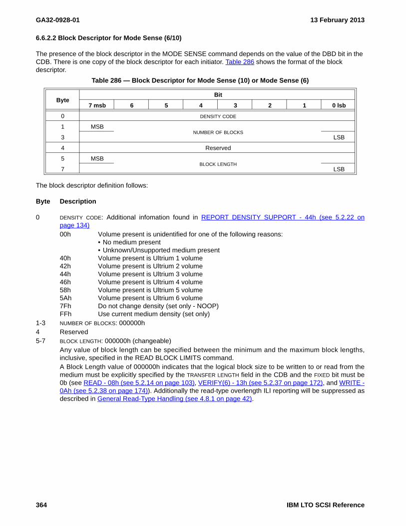
GA32-0928-01 13 February 2013
6.6.2.2 Block Descriptor for Mode Sense (6/10)
The presence of the block descriptor in the MODE SENSE command depends on the value of the DBD bit in the CDB. There is one copy of the block descriptor for each initiator. Table 286 shows the format of the block descriptor.
The block descriptor definition follows:
Byte Description
0 DENSITY CODE: Additional infomation found in REPORT DENSITY SUPPORT - 44h (see 5.2.22 onpage 134)00h Volume present is unidentified for one of the following reasons:
• No medium present • Unknown/Unsupported medium present
40h Volume present is Ultrium 1 volume42h Volume present is Ultrium 2 volume44h Volume present is Ultrium 3 volume46h Volume present is Ultrium 4 volume58h Volume present is Ultrium 5 volume5Ah Volume present is Ultrium 6 volume7Fh Do not change density (set only - NOOP)FFh Use current medium density (set only)
1-3 NUMBER OF BLOCKS: 000000h4 Reserved5-7 BLOCK LENGTH: 000000h (changeable)
Any value of block length can be specified between the minimum and the maximum block lengths,inclusive, specified in the READ BLOCK LIMITS command.A Block Length value of 000000h indicates that the logical block size to be written to or read from themedium must be explicitly specified by the TRANSFER LENGTH field in the CDB and the FIXED bit must be0b (see READ - 08h (see 5.2.14 on page 103), VERIFY(6) - 13h (see 5.2.37 on page 172), and WRITE -0Ah (see 5.2.38 on page 174)). Additionally the read-type overlength ILI reporting will be suppressed asdescribed in General Read-Type Handling (see 4.8.1 on page 42).
Table 286 — Block Descriptor for Mode Sense (10) or Mode Sense (6)
ByteBit
7 msb 6 5 4 3 2 1 0 lsb
0 DENSITY CODE
1 MSBNUMBER OF BLOCKS
3 LSB
4 Reserved
5 MSBBLOCK LENGTH
7 LSB
364 IBM LTO SCSI Reference
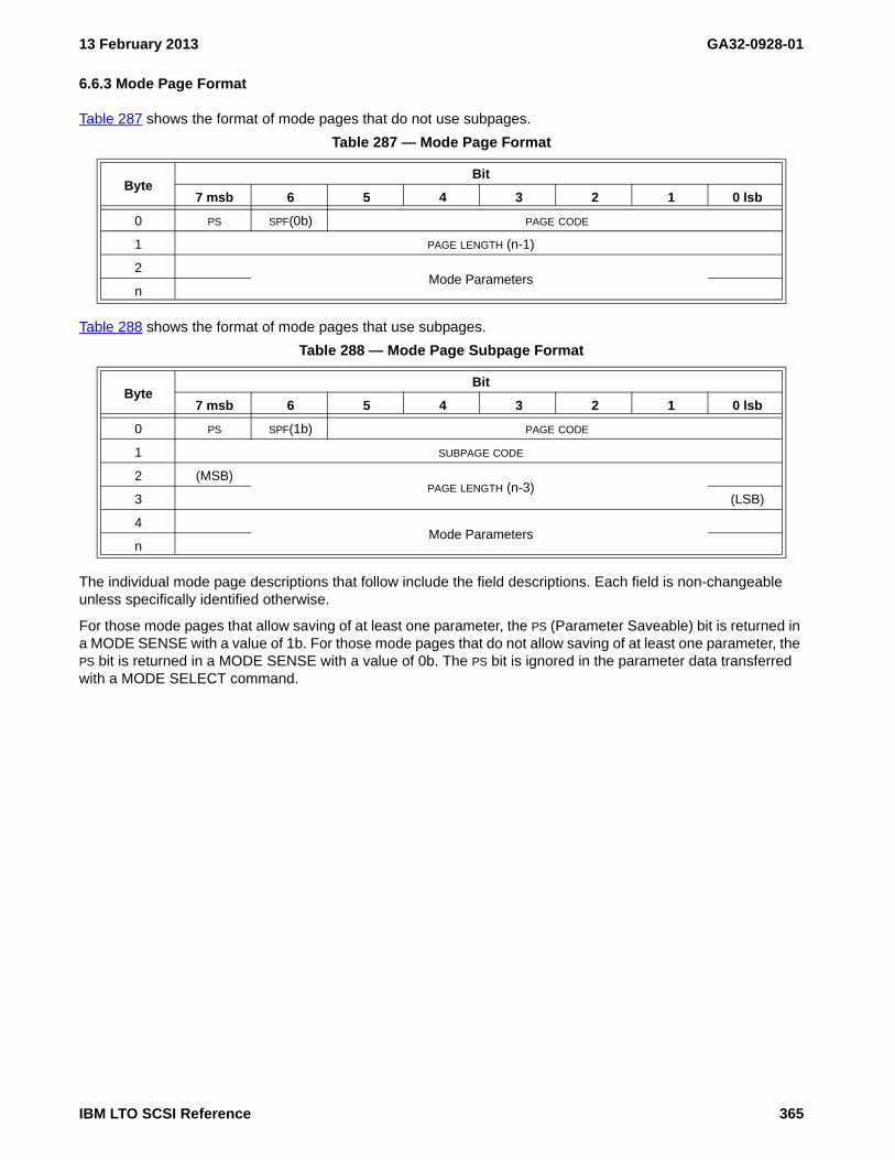
13 February 2013 GA32-0928-01
6.6.3 Mode Page Format
Table 287 shows the format of mode pages that do not use subpages.
Table 288 shows the format of mode pages that use subpages.
The individual mode page descriptions that follow include the field descriptions. Each field is non-changeable unless specifically identified otherwise.
For those mode pages that allow saving of at least one parameter, the PS (Parameter Saveable) bit is returned in a MODE SENSE with a value of 1b. For those mode pages that do not allow saving of at least one parameter, the PS bit is returned in a MODE SENSE with a value of 0b. The PS bit is ignored in the parameter data transferred with a MODE SELECT command.
Table 287 — Mode Page Format
ByteBit
7 msb 6 5 4 3 2 1 0 lsb
0 PS SPF(0b) PAGE CODE
1 PAGE LENGTH (n-1)
2Mode Parameters
n
Table 288 — Mode Page Subpage Format
ByteBit
7 msb 6 5 4 3 2 1 0 lsb
0 PS SPF(1b) PAGE CODE
1 SUBPAGE CODE
2 (MSB)PAGE LENGTH (n-3)
3 (LSB)
4Mode Parameters
n
IBM LTO SCSI Reference 365

GA32-0928-01 13 February 2013
6.6.4 Supported Mode Pages
The following standards-based mode pages are supported
MP 01h: Read-Write Error Recovery (see 6.6.5 on page 367)MP 02h: Disconnect-Reconnect (see 6.6.6 on page 369)MP 0Ah: Control (see 6.6.7 on page 371)MP 0Ah[01h]: Control Extension (see 6.6.8 on page 372)MP 0Ah[F0h]: Control Data Protection (see 6.6.9 on page 373)MP 0Fh: Data Compression (see 6.6.10 on page 375)MP 10h: Device Configuration (see 6.6.11 on page 377)MP 10h[01h]: Device Configuration Extension (see 6.6.12 on page 380)MP 11h: Medium Partition Page (see 6.6.13 on page 383)MP 18h: Protocol-Specific Logical Unit (see 6.6.14 on page 388)MP 19h: Protocol specific port (see 6.6.15 on page 390)MP 1Ah: Power Condition (see 6.6.16 on page 393)MP 1Ch: Informational Exceptions Control (see 6.6.17 on page 395)MP 1Dh: Medium Configuration (see 6.6.18 on page 397)
The following vendor-specific mode pages are also supported
MP 24h: Vendor-Specific (see 6.6.19 on page 398) (see on page 399)MP 2Fh: Behavior Configuration (see 6.6.20 on page 403)MP 30h: Device Attribute Settings (see 6.6.21 on page 407)MP 30h[01h]: Drive MAC address - Device attribute settings (see 6.6.21.3.2 on page 412)MP 30h[02h]: Drive IP address and subnet mask - Device attribute settings (see 6.6.21.3.3 on page 414)MP 30h[03h]: Key manager IP address information - Device attribute settings (see 6.6.21.3.4 on page 416)MP 30h[20h]: Encryption mode - Device Attribute Settings (see 6.6.21.4.1 on page 417)MP 30h[40h]: SkipSync - Device attribute settings (see 6.6.21.5.1 on page 418)MP 30h[42h]: End of partition behavior control - Device attribute settings (see 6.6.21.5.3 on page 422)MP 3Eh: Engineering Support (see 6.6.22 on page 423)Mode Page 3Fh: All Pages
NOTE 45 - Mode page 3Eh is for engineering use only and is not included in page 3Fh
366 IBM LTO SCSI Reference

13 February 2013 GA32-0928-01
6.6.5 MP 01h: Read-Write Error Recovery
See MODE SELECT (6/10) - 15h/55h (see 5.2.9 on page 89) for how to set these parameters and MODE SENSE (6/10) - 1Ah/5Ah (see 5.2.10 on page 91) for how to read these parameters.
This page is defined as common to all initiators.
The Read-Write Error Recovery mode page (see table 289) specifies the error recovery and reporting parameters that the device server shall use when transferring data between the device and the medium. These parameters do not affect protocol-level recovery procedures or positioning error recovery procedures.
NOTE 46 - The parameters in the Read-Write Error Recovery mode page also apply to verify operations.
Byte Description
0Bit Description7 PS (Parameter Saveable): 0b in a MODE SENSE command. Ignored in a MODE SELECT com-
mand.6 Reserved5-0 PAGE CODE: 01h
1 PAGE LENGTH: 0Ah
Table 289 — Read-Write Error Recovery mode page
ByteBit
7 msb 6 5 4 3 2 1 0 lsb
0 PS SPF(0) PAGE CODE (01h)
1 PAGE LENGTH (0Ah)
2 Reserved TB Rsvd EER PER DTE DCR
3 READ RETRY COUNT
4 Reserved
5 Reserved
6 Reserved
7 Reserved
8 WRITE RETRY COUNT
9 Reserved
10 Reserved
11 Reserved
IBM LTO SCSI Reference 367
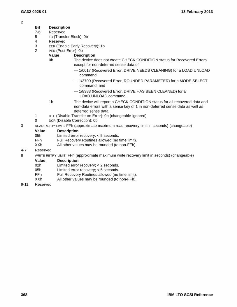
GA32-0928-01 13 February 2013
2Bit Description7-6 Reserved5 TB (Transfer Block): 0b4 Reserved3 EER (Enable Early Recovery): 1b2 PER (Post Error): 0b
Value Description0b The device does not create CHECK CONDITION status for Recovered Errors
except for non-deferred sense data of:
— 1/0017 (Recovered Error, DRIVE NEEDS CLEANING) for a LOAD UNLOAD command
— 1/3700 (Recovered Error, ROUNDED PARAMETER) for a MODE SELECT command, and
— 1/8383 (Recovered Error, DRIVE HAS BEEN CLEANED) for a LOAD UNLOAD command.
1b The device will report a CHECK CONDITION status for all recovered data and non-data errors with a sense key of 1 in non-deferred sense data as well as deferred sense data.
1 DTE (Disable Transfer on Error): 0b (changeable-ignored)0 DCR (Disable Correction): 0b
3 READ RETRY LIMIT: FFh (approximate maximum read recovery limit in seconds) (changeable)Value Description05h Limited error recovery; < 5 seconds.FFh Full Recovery Routines allowed (no time limit).XXh All other values may be rounded (to non-FFh).
4-7 Reserved8 WRITE RETRY LIMIT: FFh (approximate maximum write recovery limit in seconds) (changeable)
Value Description02h Limited error recovery; < 2 seconds.05h Limited error recovery; < 5 seconds.FFh Full Recovery Routines allowed (no time limit).XXh All other values may be rounded (to non-FFh).
9-11 Reserved
368 IBM LTO SCSI Reference

13 February 2013 GA32-0928-01
6.6.6 MP 02h: Disconnect-Reconnect
See MODE SELECT (6/10) - 15h/55h (see 5.2.9 on page 89) for how to set these parameters and MODE SENSE (6/10) - 1Ah/5Ah (see 5.2.10 on page 91) for how to read these parameters.
There is one copy of this page for each target port.
Byte Description
0Bit Description7 PS (Parameter Saveable): 0b in a MODE SENSE command. Ignored in a MODE SELECT com-
mand.6 Reserved5-0 PAGE CODE: 02h
1 PAGE LENGTH: 0Eh2 BUFFER FULL RATIO: 00h3 BUFFER EMPTY RATIO: 00h4-5 BUS INACTIVITY LIMIT: 0000h (no limit)6-7 DISCONNECT TIME LIMIT: 0000h (no limit)8-9 CONNECT TIME LIMIT: 0000h (no limit)10-11 MAXIMUM BURST SIZE: 0000h (no limit)12
Bit Description7 EMDP (Enable Modify Data Pointers): 0b6-4 FAIR ARBITRATION: 000b3 DIMM (Disconnect Immediate): 0b2-0 DTDC (Data Transfer Disconnect Word): 000b
13 Reserved
Table 290 — Disconnect-Reconnect mode page
ByteBit
7 msb 6 5 4 3 2 1 0 lsb
0 PS SPF (0b) PAGE CODE (02h)
1 PAGE LENGTH (0Eh)
2 BUFFER FULL RATIO
3 BUFFER EMPTY RATIO
4 (MSB)BUS INACTIVITY LIMIT
5 (LSB)
6 (MSB)DISCONNECT TIME LIMIT
7 (LSB)
8 (MSB)CONNECT TIME LIMIT
9 (LSB)
10 (MSB)MAXIMUM BURST SIZE
11 (LSB)
12 EMDP FAIR ARBITRATION DIMM DTDC
13 Reserved
14 (MSB)FIRST BURST SIZE
15 (LSB)
IBM LTO SCSI Reference 369

GA32-0928-01 13 February 2013
14-15 First Burst Size: 0000h
370 IBM LTO SCSI Reference

13 February 2013 GA32-0928-01
6.6.7 MP 0Ah: Control
See MODE SELECT (6/10) - 15h/55h (see 5.2.9 on page 89) for how to set these parameters and MODE SENSE (6/10) - 1Ah/5Ah (see 5.2.10 on page 91) for how to read these parameters.
There is one copy of this page for each initiator.
Byte Description
0Bit Description7 PS (Parameter Saveable): 0b in a MODE SENSE command. Ignored in a MODE SELECT com-
mand.6 Reserved5-0 Page Code: 0Ah
1 Page Length: 0Ah2
Bit Description7-5 TST (Task Set Type): 000b4-2 Reserved1 GLTSD (Global Logging Target Save Disable): 0b0 RLEC (Report Log Exception Condition): 0b
3Bit Description7-4 Queue Algorithm Modifier: 0000b3-2 Reserved1 QErr (Queue Error): 0b0 DQue (Disable Queuing): 1b
4Bit Description7 Reserved6 RAC (Report A Check): 0b5-3 Reserved2 RAERP (Ready Asynchronous Event Reporting): 0b1 UAAERP (Unit Attention Asynchronous Event Reporting): 0b0 EAERP (Error Asynchronous Event Reporting): 0b
5 Reserved6-7 Ready AEN Holdoff Period: 0000h
If AEN is disabled (Byte 4 bit 2 = 0b), this field is not meaningful.8-9 Busy time-out period: FFFFh10 Reserved11 Reserved
IBM LTO SCSI Reference 371

GA32-0928-01 13 February 2013
6.6.8 MP 0Ah[01h]: Control Extension
See MODE SELECT (6/10) - 15h/55h (see 5.2.9 on page 89) for how to set these parameters and MODE SENSE (6/10) - 1Ah/5Ah (see 5.2.10 on page 91) for how to read these parameters.
The mode page policy is shared.
Byte Description
0Bit Description7 PS (Parameter Saveable): 0b in a MODE SENSE command. Ignored in a MODE SELECT com-
mand.6 SPF: 1b5-0 PAGE CODE: 0Ah
1 SUBPAGE CODE: 01h2-3 PAGE LENGTH: 1Ch4
Bit Description7-3 Reserved2 TCMOS (Timestamp Changeable by Methods Outside this Standard)
A TCMOS bit set to one specifies that the timestamp may be initialized by methods outside the scope of this standard (for example The LDI Set Timestamp command). A TCMOS bit set to zero specifies that the timestamp shall not be changed by any method except those defined by this standard.
1 SCSIP (SCSI precedence)
A SCSIP bit set to one specifies that the timestamp changed using a SET TIMESTAMP command takes precedence over methods outside the scope of this standard (for example the LDI Set Timestamp command). A SCSIP bit set to zero specifies that methods outside this standard (for example the LDI Set Timestamp command) may change the timestamp and that the SET TIMESTAMP command is illegal.
0 IALUAE (implicit asymmetric logical unit access enabled): 0b5
Bit Description7-4 Reserved3-0 INITIAL COMMAND PRIORITY: 0h
6-31 Reserved
Table 291 — Control Extension mode page
ByteBit
7 msb 6 5 4 3 2 1 0 lsb
0 PS SPF (1b) PAGE CODE (0Ah)
1 SUBPAGE CODE (01h)
2 (MSB)PAGE LENGTH (1Ch)
3 (LSB)
4 Reserved TCMOS SCSIP IALUAE
5 Reserved INITIAL COMMAND PRIORITY
6Reserved
31
372 IBM LTO SCSI Reference

13 February 2013 GA32-0928-01
6.6.9 MP 0Ah[F0h]: Control Data Protection
See MODE SELECT (6/10) - 15h/55h (see 5.2.9 on page 89) for how to set these parameters and MODE SENSE (6/10) - 1Ah/5Ah (see 5.2.10 on page 91) for how to read these parameters.
The Control Data Protection mode page provides controls that allow selective use of logical block protection. Logical block protection (see 4.5 on page 35) describes how this page is used to control logical block protection.
The mode page policy of this page is Per I_T nexus.
Byte Description
0Bit Description
7 PS (Parameter Saveable): 1b in a MODE SENSE command. Ignored in a MODE SELECT command.
6 SPF: 1b5-0 PAGE CODE: 28h
1 SUBPAGE CODE: 01h2-3 PAGE LENGTH: 1Ch4 LOGICAL BLOCK PROTECTION METHOD:
Value Description00h Do not use logical block protection01h Use the Reed-Solomon CRC as defined in ECMA-319 as the logical block protection informa-
tion.others Reserved.
5Bit Description7-6 Reserved5-0 LOGICAL BLOCK PROTECTION INFORMATION LENGTH: 04h.
6Bit Description7 LBP_W (logical blocks protected during write): 0 (changeable)
Shall be set to zero if the LOGICAL BLOCK PROTECTION METHOD field is set to zero.
Value Description0 Protection information is not included with logical blocks transferred when writing.1b Protection information is included with logical blocks transferred during
commands specified in .Protecting logical blocks transferred during writes (see
Table 292 — Control Data Protection mode page format
ByteBit
7 6 5 4 3 2 1 0
0 PS SPF(1b) PAGE CODE (0Ah)
1 SUBPAGE CODE (F0h)
2 (MSB)PAGE LENGTH (28)
3 (LSB)
4 LOGICAL BLOCK PROTECTION METHOD
5 Reserved LOGICAL BLOCK PROTECTION INFORMATION LENGTH
6 LBP_W LBP_R RBDP Reserved
7 Reserved
8Reserved
31
IBM LTO SCSI Reference 373

GA32-0928-01 13 February 2013
4.5.4 on page 37).6 LBP_R (logical block protected during read): 0 (changeable)
Shall be set to zero if the LOGICAL BLOCK PROTECTION METHOD field is set to zero.
Value Description0 Protection information is not included with logical blocks transferred when
reading.1b Protection information is included with logical blocks transferred during
commands specified in Protecting logical blocks transferred during reads (see 4.5.5 on page 38).
5 RBDP (recover buffered data protected): 0b (non-changeable)4-0 Reserved
7-31 Reserved
374 IBM LTO SCSI Reference

13 February 2013 GA32-0928-01
6.6.10 MP 0Fh: Data Compression
See MODE SELECT (6/10) - 15h/55h (see 5.2.9 on page 89) for how to set these parameters and MODE SENSE (6/10) - 1Ah/5Ah (see 5.2.10 on page 91) for how to read these parameters.
The Data Compression mode page (see table 293) specifies the parameters for the control of data compression in the device.
This page is defined as common to all initiators.
Byte Description
0Bit Description7 PS (Parameter Saveable): 0b in a MODE SENSE command. Ignored in a MODE SELECT com-
mand.6 Reserved5-0 PAGE CODE: 0Fh
1 PAGE LENGTH: 0Eh2
Bit Description7 DCE (Data Compression Enabled): 1b
Value Description0 Data compression is not enabled1 Data compression is enabled
NOTE 47 - The only advantage to disabling data compression is predictable full tape capacity(see 2.1.39)
NOTE 48 - When the SELECT DATA COMPRESSION ALGORITHM field of MP 10h: DeviceConfiguration (see 6.6.11) is set to one the DCE bit is forced to one, even if both pages arereceived in the same MODE SELECT command.
6 DCC (Data Compression Capable): 1b5-0 Reserved
Table 293 — Data Compression mode page
ByteBit
7 msb 6 5 4 3 2 1 0 lsb
0 PS SPF(0) PAGE CODE (0Fh)
1 PAGE LENGTH (0Eh)
2 DCE DCC Reserved
3 DDE RED Reserved
4 (MSB)COMPRESSION ALGORITHM
7 (LSB)
8 (MSB)DECOMPRESSION ALGORITHM
11 (LSB)
12Reserved
15
IBM LTO SCSI Reference 375

GA32-0928-01 13 February 2013
3Bit Description7 DDE: 1b6-5 RED (Report Exception on Decompression): 00b4-0 Reserved
4-7 COMPRESSION ALGORITHM: 000000FFh (Unregistered algorithm)8-11 DECOMPRESSION ALGORITHM: 000000FFh (Unregistered algorithm)12-15 Reserved
376 IBM LTO SCSI Reference

13 February 2013 GA32-0928-01
6.6.11 MP 10h: Device Configuration
See MODE SELECT (6/10) - 15h/55h (see 5.2.9 on page 89) for how to set these parameters and MODE SENSE (6/10) - 1Ah/5Ah (see 5.2.10 on page 91) for how to read these parameters.
The Device Configuration mode page (see table 294) is used to specify the configuration of items specific to tape drives.
This page is defined as common to all initiators.
Byte Description
0Bit Description7 PS (Parameter Saveable): 1b in a MODE SENSE command. Ignored in a MODE SELECT com-
mand.6 SPF: 0b5-0 PAGE CODE: 10h
1 PAGE LENGTH: 0Eh2
Bit Description7 Reserved6 CAP (Change Active Partition): 0b (Obsolete - Refer to the LOCATE command to change parti-
tion)5 CAF (Change Active Format): 0b (non-changeable)4-0 ACTIVE FORMAT: 00000b (non-changeable)
3 ACTIVE PARTITION (non-changeable)4 WRITE BUFFER FULL RATIO: 00h (value not specified) (non-changeable)
Table 294 — Device Configuration mode page
ByteBit
7 msb 6 5 4 3 2 1 0 lsb
0 PS SPF(0) PAGE CODE (10h)
1 PAGE LENGTH (0Eh)
2 Rsvd Obsolete CAF ACTIVE FORMAT
3 ACTIVE PARTITION
4 WRITE OBJECT BUFFER FULL RATIO
5 READ OBJECT BUFFER EMPTY RATIO
6 (MSB)WRITE DELAY TIME
7 (LSB)
8 OBR LOIS Obsolete AVC SOCF ROBO REW
9 Obsolete
10 EOD DEFINED EEG SEW SWP BAML BAM
11 (MSB)OBJECT BUFFER SIZE AT EARLY WARNING
13 (LSB)
14 SELECT DATA COMPRESSION ALGORITHM
15 WTRE OIR REWIND ON RESET ASOCWP PERSWP PRMWP
IBM LTO SCSI Reference 377

GA32-0928-01 13 February 2013
5 READ BUFFER EMPTY RATIO: 00h (value not specified) (non-changeable)6-7 WRITE DELAY TIME: 0014h (about 2 sec) (changeable)
The maximum time, in 100 ms increments, that the device server waits before any buffered data that is tobe written, is forced to the medium after the last buffered WRITE command that did not cause the objectbuffer to exceed the write object buffer full ratio.
WARNING WARNING
WARNING WARNING
Changing the WRITE DELAY TIME may result in adverse performance.
8Bit Description7 OBR (Object Buffer Recovery): 0b (non-changeable)6 LOIS (Logical Object Identifier Supported): 1b (non-changeable)5 Obsolete4 AVC (Automatic Velocity Control): 0b (non-changeable)
The speed chosen is defined by the SPEED field in the mode parameter header.
3-2 SOCF (Stop on Consecutive Filemarks): 00b (non-changeable)
Read ahead to fill buffer, without regard for filemarks
1 RBO (Recover Buffer Order): 0b (non-changeable)0 REW (Report Early Warning): 0b (non-changeable)
9 GAP SIZE: 00h (non-changeable)10
Bit Description7-5 EOD DEFINED (End Of Data Defined): 000b (non-changeable)4 EEG (Enable EOD Generation): 1b (non-changeable)3 SEW (Synchronize at Early-Warning): 0b (non-changeable)
The device may retain unwritten buffered logical objects in the object buffer when positioned between early-warning and EOP.
2 SWP (Soft Write Protect): 0b (non-changeable)1 BAML (Block Address Mode Lock): 0b (non-changeable)0 BAM (Block Address Mode): 0b (non-changeable)
11-13 OBJECT BUFFER SIZE AT EARLY WARNING: 000000h (non-changeable)14 SELECT DATA COMPRESSION ALGORITHM: 01h (changeable)
Value Description00h No compression used
NOTE 49 - The only advantage to disabling data compression is predictable full tape capacity(see 2.1.39)
01 Use default compression algorithm
NOTE 50 - On a MODE SENSE, the value of byte 14 is consistent with what is found in ModePage 0F, Byte 2, Bit 7. If this byte alone is updated on a MODE SELECT, and Mode Page 0F isnot sent, then Mode Page 0F, Byte 2, Bit 7 is updated according to this field. If both Page 10and Page 0F are sent, then if either setting is enabled, then compression will be enabled andboth fields updated to reflect enablement.
15Bit Description7-6 WTRE (WORM Tamper Read Enable): 10b (changeable)
Value Description00b The device treats a value of 00b the same as if the value were 10b.01b Detection of compromised integrity on a WORM medium shall not affect
processing of a task.
378 IBM LTO SCSI Reference

13 February 2013 GA32-0928-01
NOTE 51 - An application client should not set the WTRE bit to 01b except for the recovery ofdata from a WORM medium where the integrity of the stored data has been compromised.
10b If the drive detects compromised integrity on a WORM medium it returns CHECK CONDITION status with the sense key set to MEDIUM ERROR and the additional sense code set to WORM MEDIUM - INTEGRITY CHECK. (3/300Dh).
The position of the medium may have changed.
11b Reserved5 OIR (Only If Reserved) 0b (changeable) (saveable)
This field dictates the behavior of commands other than PERSISTENT RESERVE IN, PERSISTENT RESERVE OUT, RESERVE, and RELEASE.
Value Description0b Commands processed normally when no reservation exists.per RVC column of
Table 27, Supported Common SCSI Commands on page 701b Commands listed with a ‘Y’ in the RVC column of Table 27, Supported Common
SCSI Commands on page 70 are rejected with ILLEGAL REQUEST, NOT RESERVED if received and no reservation is present in the drive. If a reservation is present in the drive, the commands are processed only if a reservation exists that allows access via the I_T nexus from which the command is received.
4-3 REWIND ON RESET: 10b (non-changeable)
The position on medium is not changed due to a logical unit reset.
2 ASOCWP (Associated Write Protect): 0b (non-changeable)1 PERSWP (Persistent Write Protect) 0b (non-changeable)0 PRMWP (Permanent Write Protect): 0b (non-changeable)
IBM LTO SCSI Reference 379

GA32-0928-01 13 February 2013
6.6.12 MP 10h[01h]: Device Configuration Extension
See MODE SELECT (6/10) - 15h/55h (see 5.2.9 on page 89) for how to set these parameters and MODE SENSE (6/10) - 1Ah/5Ah (see 5.2.10 on page 91) for how to read these parameters.
The Device Configuration Extension mode page (see table 295), a subpage of the Device Configuration mode page, provides control of the SCSI features specific to sequential-access devices. The Device Configuration Extension mode page uses the shared mode page policy (see SPC-4).
The parameter saveable (PS) bit is set to one in the MODE SENSE command indicating that the changeable parameters in the mode page shall be saveable by issuing a MODE SELECT command with the SP bit set to one. The PS bit is ignored in a MODE SELECT command.
A TapeAlert prevent LOG SENSE deactivation (TAPLSD) bit set to one specifies that the device server shall not alter the value of implemented TapeAlert FLAG parameters due to processing of a LOG SENSE command with the PAGE CODE field set to 2Eh. A TAPLSD bit set to zero specifies that, as part of the processing of a LOG SENSE command with the PAGE CODE field set to 2Eh, the device server shall deactivate every supported TapeAlert flag.
A TapeAlert respect page control (TARPC) bit set to one specifies that the device server shall select the type of parameter values for the TapeAlert log page using the value of the PC field in a LOG SELECT or LOG SENSE command (see SPC-4). A TARPC bit set to zero specifies that the device server shall select cumulative parameter values for the TapeAlert log page regardless of the value of the PC field in a LOG SELECT or LOG SENSE command.
NOTE 52 - An application client using the TapeAlert threshold usage model should set the TARPC bit to one.
A TapeAlert Select exception reporting (TASER) bit set to one specifies that:
a) activation of a TapeAlert flag shall not result in an informational exception condition; andb) activation or deactivation of a TapeAlert flag may result in the generation of a unit attention condition with
the additional sense code set to THRESHOLD CONDITION MET depending on the value of the ETC bit in each parameter in the TapeAlert log page.
A TASER bit set to zero specifies that:
a) activation of a TapeAlert flag shall result in an informational exception condition;b) activation or deactivation of a TapeAlert flag shall not result in the generation of a unit attention condition
with the additional sense code set to THRESHOLD CONDITION MET; andc) the device server shall set the ETC bit in each parameter of the TapeAlert log page to zero.
Table 295 — Device Configuration Extension mode page
ByteBit
7 msb 6 5 4 3 2 1 0 lsb
0 PS SPF(1b) PAGE CODE (10h)
1 SUBPAGE CODE (01h)
2 (MSB)PAGE LENGTH (1Ch)
3 (LSB)
4 Reserved TARPF TASER TARPC TAPLSD
5 WRITE MODE SHORT ERASE MODE
6 (MSB)PEWS
7 (LSB)
8 Reserved VCELBRE
9Reserved
31
380 IBM LTO SCSI Reference

13 February 2013 GA32-0928-01
The device server may provide independent sets of TapeAlert log parameters for each I_T nexus (see SPC-4). If the device server does not support independent sets of TapeAlert log parameters and the processing of a MODE SELECT command with the TASER bit set to zero results in a change in the value of the ETC bit in a TapeAlert log parameter, then the device server shall establish a unit attention condition (see SAM-4) for the initiator port associated with every I_T nexus, except the I_T nexus on which the MODE SELECT command was received, with the additional sense code set to LOG PARAMETERS CHANGED.
A TapeAlert respect parameter fields (TARPF) bit set to one specifies that the device server shall select the parameters of the TapeAlert log page to report in response to a LOG SENSE command using the values of the PPC bit and the PARAMETER POINTER field (see SPC-4). A TARPF bit set to zero specifies that the device server shall report all TapeAlert log page parameters regardless of the values of the PPC bit and the PARAMETER POINTER field.
The SHORT ERASE MODE field specifies the action to be taken by the device server when an ERASE (16) or ERASE (6) command with the LONG bit set to zero is processed. The values for the SHORT ERASE MODE field are specified in table 296. The Ultrium 5 drive sets this field to 02h.
The WRITE MODE field specifies the write mode (see 4.1) in which to place the device server. The values for the WRITE MODE field are specified in table 297. Ultrium 5 devices support a value of 00h or 01h. If a volume is loaded and an attempt is made to change the WRITE MODE from 01h (i.e., append-only) to 00h (i.e., overwrite-allowed), then the command shall be rejected with ILLEGAL REQUEST, INVALID FIELD IN PARAMETER LIST
The programmable early warning size (PEWS) field specifies the number of megabytes (i.e., 106) native capacity to use in establishing a PEWZ. See (see 4.4) for a description of programmable early warning. Ultrium 4 and earlier drives do not support the PEWS field and require that it be set to 0000h. The Ultrium 5 and later drives support the PEWS field set to any value and does not round the value (e.g., due to volume capacity). The default value is 0000h indicating that there is no PEWZ.
NOTE 53 - It is possible that a partition is set to a capacity less than the size that can be represented by the PEWS field. In this case the first write will get the programmable early warning indication.
NOTE 54 - PEWZ will be created using the amount of medium required to fit PEWS megabytes assuming one-to-one compression (e.g., compression disabled) and the medium is in good condition.
NOTE 55 - The drive employs a design to protect against the number of blocks on medium exceeding a value that can be represented in a 4-byte field. To ensure the programmable early warning indication is reported to an application during this scenario, the drive also uses the number of blocks on medium as a determination of entering PEWZ. The drive calculates how many blocks it will take to fill PEWZ assuming a modest block size of 32KiB (i.e., PEWS/8000h = number_of_blocks_to_make_PEWZ) and reports programmable early warning when the number of blocks on medium reaches PEWZ (i.e., Early Warning - number_of_blocks_to_make_PEWZ).
Table 296 — SHORT ERASE MODE field
Value Description
00h Not Supported
01h Not Supported
02h The device server shall record an EOD indication at the specified location on the medium.
03h - FFh Reserved
Table 297 — WRITE MODE field
Value Description
00h overwrite-allowed mode (see 4.1.2).
01h append-only mode (see 4.1.3).
02h - EFh Reserved
F0h - FFh Vendor-specific
IBM LTO SCSI Reference 381

GA32-0928-01 13 February 2013
If the volume containing encrypted logical blocks requires encryption (VCELBRE) bit is set to one and the VCELB bit in the Data Encryption Status page is set to one, then the device server shall require that any logical blocks written to the medium are encrypted (see SSC-4). If the VCELBRE bit is set to zero, then the device server does not use the VCELB bit in the Data Encryption Status page to determine if encryption is required for writing logical blocks. The encryption mode (see 4.10) setting determines the behavior of the VCELBRE bit. This interaction is described in table 298.
Table 298 — VCELBRE behavior related to encryption modes
Encryption modeVCELBRE is
Set to Changeable on LUN 0
AME 0b Yes
Transparent Encryption - IBM (e.g., LME) 1b No
ADC Controlled 1b Yes
ADC Controlled — ADC tape data encryption (see ADC-3) using External data encryption control (see SSC-3).AME — Application Managed Encryption using in-band methods of controlling encryption (e.g., Logical block encryption described in SSC-3 or the method used by TSM).Transparent Encryption - IBM — Application transparent encryption using a proxy to the IBM EKM or TKLM (e.g., LME; SME).
382 IBM LTO SCSI Reference

13 February 2013 GA32-0928-01
6.6.13 MP 11h: Medium Partition Page
See MODE SELECT (6/10) - 15h/55h (see 5.2.9 on page 89) for how to set these parameters and MODE SENSE (6/10) - 1Ah/5Ah (see 5.2.10 on page 91) for how to read these parameters.
This page is defined as common to all initiators.
The Medium Partition mode page (see table 299) is used to specify the group of medium partitions. Fields in the Medium Partition mode page indicating the current state of the partitions for the medium are changed by the device server to the current medium state on a not ready to ready transition when the medium state changes from demounted to mounted.
The FORMAT MEDIUM command uses the settings in the Medium Partition mode page and functions in the constraints dictated by any capacity changes resulting from a previous SET CAPACITY command that was performed on the mounted volume (i.e., The Set Capacity command controls the maximum capacity allowed for the volume and the Format Medium command works inside those constraints).
The partitioning of the mounted volume is not changed until a subsequent FORMAT MEDIUM command is issued while the volume is mounted.
WARNING WARNINGThe fields in this page do not follow normal mode parameter rules. Some fields always return values depending on the mounted volume even after a MODE SELECT command changes them. Other fields return pending values set by a MODE SELECT command instead of values dictated by the mounted volume. Check each field
WARNING WARNING
description to understand this behavior.
There is an overhead associated with each additional partition, regardless of the size of the partition, that subtracts from the customer data space on the volume. The larger the number of possible partitions, the more overhead is consumed when the volume is partitioned.
Partitioning and reformatting (see 4.2.5 on page 32) describes restrictions on partitioning.
IBM LTO SCSI Reference 383

GA32-0928-01 13 February 2013
Byte Description
0Bit Description7 PS (Parameter Saveable): 0b in a MODE SENSE command. Ignored in a MODE SELECT com-
mand.6 SPF (SubPage Format): 0b5-0 PAGE CODE: 11h
1 PAGE LENGTH:The page leng th depends on the number o f par t i t i ons on the vo lume ( i .e . , 08h +2*ADDITIONAL PARTITIONS DEFINED).
2 MAXIMUM ADDITIONAL PARTITIONS: (non-changeable)This field specifies the maximum number of additional partitions supported on the loaded volume. It canbe thought of as the value N-1 where N is the maximum number of partitions allowed. In a MODESENSE command the MAXIMUM ADDITIONAL PARTITIONS field is set to the value indicated by the loadedvolume, or the value reported for the previously loaded volume if there is no volume loaded. If there hasbeen no volume loaded since power-on or the mounted volume does not support partitioning (e.g.,WORM volume), then the MAXIMUM ADDITIONAL PARTITIONS field is set to 00h.This value may be changed by the device if:A) a volume is loaded; orB) other unspecified events occur.
Table 299 — Medium Partition mode page
ByteBit
7 msb 6 5 4 3 2 1 0 lsb
0 PS(0b) SPF(0b) PAGE CODE (11h)
1 PAGE LENGTH (n-1)
2 MAXIMUM ADDITIONAL PARTITIONS
3 ADDITIONAL PARTITIONS DEFINED
4 FDP SDP IDP PSUM (11b) POFM (1b)) CLEAR (0b) ADDP(0b)
5 MEDIUM FORMAT RECOGNITION (03h)
6 PARTITIONING TYPE PARTITION UNITS
7 Reserved
Partition size descriptor(s)
8 (MSB)PARTITION SIZE (first)
9 (LSB)
n-1 (MSB)PARTITION SIZE (last)
n (LSB)
384 IBM LTO SCSI Reference

13 February 2013 GA32-0928-01
3 ADDITIONAL PARTITIONS DEFINED:This field specifies the number of additional partitions on the mounted volume (in addition to partition 0).It can be thought of as the value N-1 where N is the total number of partitions.If SDP or IDP is set to one, then this field may be set to 00h, 01h, 02h, or 03h.If FDP is set to one, then this field is ignored (i.e., any value is allowed and ignored).This field is not allowed to changed when the drive is not ready.The partitioning of the mounted volume is not changed until a subsequent Format Medium command isissued while the volume is mounted. If the logical unit is not ready, the ADDITIONAL PARTITIONS DEFINED
field is undefined.
NOTE 56 - If a MODE SENSE command is received after a MODE SELECT command but before a FORMAT MEDIUM command, then the ADDITIONAL PARTITIONS DEFINED value returned may not match the value sent in the MODE SELECT command but the device server retains the value sent in the MODE SELECT command until the FORMAT MEDIUM command is performed.
4Bit Description7 FDP (Fixed Data Partitions):
A FDP bit of one in a MODE SELECT command specifies the logical unit shall partition the medium based on its fixed definition of partitions. Setting this bit to one is mutually exclusive with the SDP and IDP bits. The partition size descriptors are ignored by the MODE SELECT command when the FDP bit is set to one. The drive creates two partitions on the volume and assigns one partition as the minimum sized partition and one partition as the remaining available size.
When a MODE SENSE command is received after a MODE SELECT command but before a FORMAT MEDIUM command the FDP bit returned is the value that was set in the MODE SELECT command. When a MODE SENSE command is received and there is no pending change related to a MODE SELECT command for this page the FDP bit is set to zero.
NOTE 57 - The partition size descriptors are present in MODE SENSE data regardless of thesettings of the FDP, SDP or IDP fields to give an estimate of the size of each partition.
6 SDP (Select Data Partitions):
For Mode Select, either value is allowed
Value Description0b The SDP functionality is not used.1b The volume is partitioned into the number of partitions as specified by the
ADDITIONAL PARTITIONS DEFINED field (n) using partitions as close to equal size as possible. If rounding is required to meet format requirements, partitions will be rounded up from the equal size and the last partition (i.e., n + 1) will use the remaining capacity. The drive partitions the volume into n+1 partitions numbered 0 through n. Setting this bit to one is mutually exclusive with the FDP and IDP fields. The partition size descriptors are ignored by the MODE SELECT command when the SDP bit is set to one.
If a MODE SENSE command is received after a MODE SELECT command but before a FORMAT command, then the SDP bit returned is the value that was set in the MODE SELECT command. If a MODE SENSE command is received and there is no pending change related to a MODE SELECT command for this page,then the SDP bit is set to zero.
5 IDP (Initiator Defined Partitions):
For Mode Select, either value is allowed
Value Description0b The IDP functionality is not used.1b The volume is partitioned as specified by the ADDITIONAL PARTITIONS DEFINED field
and the partition size descriptors. Setting this bit to one is mutually exclusive with the FDP and SDP fields. The number of non-zero partition size descriptors received
IBM LTO SCSI Reference 385

GA32-0928-01 13 February 2013
in the Medium Partition mode page shall be at least one more than the ADDITIONAL PARTITIONS DEFINED value. The size of partition 0 shall be non-zero.
If a MODE SENSE command is received after a MODE SELECT command but before a FORMAT MEDIUM command,then the IDP bit returned is the value that was set in the MODE SELECT command. If a MODE SENSE command is received and there is no pending change related to a MODE SELECT command for this page,then the IDP bit is set to one.
4-3 PSUM (Partition Size Unit of Measure): 11b (10(PARTITION UNITS) bytes)2 POFM (Partition on Format Medium): 1b
This bit indicates that the Mode Select command will not cause changes to the partition sizes or user data, either recorded or buffered. Actual media partitioning occurs with a subsequent Format Medium command using the mode data for this page. Field values specified by a Mode Select command for this page will not be changed by the drive before the volume is unloaded or the drive is reset. Some field checking may be performed by the MODE SELECT command. However, there is no guarantee that any subsequent partitioning during a FORMAT MEDIUM command will complete with no errors.
1 CLEAR (Partition clearing): 0b0 ADDP (Adding Partitions): 0bThe drive does not retain the method used to partition the volume. The device server sets the IDP field toone in the MODE SENSE data. If a volume was previously partitioned through a MODE SELECTcommand with FDP or SDP set to one, the device server sets IDP to one in subsequent MODE SENSEdata since the volume has been initiator partitioned.Table 10 on page 30 shows the partition sizes that result from a MODE SELECT with the indicated fieldsettings if the SET CAPACITY command has not shortened the tape.Wrap-wise Partitioning (see 4.2.2 on page 28) describes how to set partition sizes and achieve desiredresults.
5 MEDIUM FORMAT RECOGNITION: 03h (Capable of format and partition recognition)6
Bit Description7-4 PARTITIONING TYPE:
The PARTITIONING TYPE field specifies the criteria used to create the partitions.
Value Description0h The type of partitioning is vendor-specific or unknown
The drive sets the PARTITIONING TYPE field to a value of 1h when a 0h is received in a MODE SELECT command. If the volume is not partitioned this value is returned in a MODE SENSE command unless there is a pending action from a MODE SELECT
1h The type of partitioning is optimized for streaming performance (i.e., wrap-wise partitioning).
2h Not Supported3h-Eh ReservedFh For a MODE SELECT command this value is reserved.
When a MODE SENSE command is received after a MODE SELECT command but before a FORMAT MEDIUM command the PARTITIONING TYPE field returned is the value that was set in the MODE SELECT command. When a MODE SENSE command is received and there is no pending change related to a MODE SELECT command for this page the PARTITIONING TYPE field is set depending on how the volume is currently partitioned.
3-0 PARTITION UNITS:
If the PSUM field is set to 11b, then each PARTITION SIZE descriptor specifies the size of a partition
in 10PARTITION UNITS bytes. The PARTITION UNITS used to partition the volume are not retained.
7 Reserved
386 IBM LTO SCSI Reference

13 February 2013 GA32-0928-01
8-n PARTITION SIZE descriptors: (n=9, 11, 13, or 15)Each PARTITION SIZE descriptor specifies the size of a partition in 10PARTITION UNITS bytes. The devicerounds any value received in a PARTITION SIZE descriptor down to the nearest valid partition size that isless than or equal to the requested value.Byte Description8-9 PARTITION SIZE descriptor for partition 00h
This shall exist and shall be non-zero.
10-11 PARTITION SIZE descriptor for partition 01h, if sent
This descriptor shall be present and non-zero if the ADDITIONAL PARTITIONS DEFINED field is 01h or greater. On Ultrium 5 and later devices this descriptor may be present and set to zero if the ADDITIONAL PARTITIONS DEFINED field is 00h.
12-13 PARTITION SIZE descriptor for partition 02h, if sent
This descriptor shall be present and non-zero if the ADDITIONAL PARTITIONS DEFINED field is 02h or greater. On Ultrium 6 and later devices this descriptor may be present and set to zero if the ADDITIONAL PARTITIONS DEFINED field is less than 02h.
14-15 PARTITION SIZE descriptor for partition 03h, if sent
This descriptor shall be present and non-zero if the ADDITIONAL PARTITIONS DEFINED field is 03h. On Ultrium 6 and later devices this descriptor may be present and set to zero if the ADDITIONAL PARTITIONS DEFINED field is less than 03h.
NOTE 58 - Summing the partition sizes provides a standardized mechanism for an initiator tocalculate the volume capacity with MODE SENSE.
In a MODE SELECT command:a) a value of FFFFh received in a PARTITION SIZE descriptor, requests that the logical unit allocate
all remaining partition space to that partition;b) if the FDP bit is set to one any values are allowed in the PARTITION SIZE descriptors and ignored.
The PARTITION SIZE descriptors are updated by the drive when an initiator specifies a newnumber of partitions;
c) if the SDP bit is set to one any values are allowed in the PARTITION SIZE descriptors and ignored.The PARTITION SIZE descriptors are updated by the drive when an initiator specifies a newnumber of partitions; and
d) the device server returns CHECK CONDITION status with the Sense Key set to ILLEGALREQUEST and the additional sense code set to INVALID FIELD IN PARAMETER LIST if:A) insufficient space exists on the volume for the requested partition sizes; orB) multiple partition size descriptors are set to FFFFh.
In a MODE SENSE command:a) a value of FFFFh returned in a PARTITION SIZE descriptor, indicates the partition size, in units
indicated by PSUM and PARTITION UNITS, is greater than or equal to FFFFh;b) if the logical unit is not ready, then thePARTITION SIZE descriptors are undefined;c) if a MODE SELECT command has modified values in this page but a FORMAT MEDIUM
command has not yet been processed, then the values in the PARTITION SIZE fields are thevalues set by the MODE SELECT command rounded to a valid partition size as described intable 10 on page 30; and
d) if the logical unit is ready and there is no pending change related to a MODE SELECT commandfor this page, then the PARTITION SIZE fields reflect the size on the volume of the related partition.
NOTE 59 - When more than one partition is defined, the sum of the partition sizes may be less than when only a single partition is defined. Each partition requires a certain amount of overhead space on a volume, which reduces the usable customer data space.
IBM LTO SCSI Reference 387

GA32-0928-01 13 February 2013
6.6.14 MP 18h: Protocol-Specific Logical Unit
See MODE SELECT (6/10) - 15h/55h (see 5.2.9 on page 89) for how to set these parameters and MODE SENSE (6/10) - 1Ah/5Ah (see 5.2.10 on page 91) for how to read these parameters.
There is one copy of this page for each target port.
The Protocol-specific logical unit mode page for FCP attached devices is defined in 6.6.14.1.
The Protocol-specific logical unit mode page for SAS attached devices is defined in 6.6.14.2.
6.6.14.1 Fibre Channel Logical Unit (18h)
.
Byte Description
0Bit Description7 PS (Parameter Saveable): 0b in a MODE SENSE command. Ignored in a MODE SELECT com-
mand.6 Reserved5-0 PAGE CODE: 18h
1 PAGE LENGTH: 06h2
Bit Description7-1 Reserved3-0 PROTOCOL IDENTIFIER: 0h (FCP)
3Bit Description7-1 Reserved0 EPDC (Enable Precise Delivery Control): 1b (changeable)
Value Description0b Do not use the FCP precise delivery function and ignore the contents of the
COMMAND REFERENCE NUMBER field in the FCP_CMND IU.1b Use the FCP precise delivery function (checking the contents of the COMMAND
REFERENCE NUMBER field in the FCP_CMND IU) to ensure that command packets are delivered in order.
4-7 Reserved
Table 300 — Fibre Channel Logical Unit mode page
ByteBit
7 msb 6 5 4 3 2 1 0 lsb
0 PS SPF (0b) PAGE CODE (18h)
1 PAGE LENGTH (n-1)
2 Reserved PROTOCOL IDENTIFIER
3 Reserved EPDC
4Reserved
n
388 IBM LTO SCSI Reference

13 February 2013 GA32-0928-01
6.6.14.2 SAS Logical Unit (18h)
.
Byte Description
0Bit Description7 PS (Parameter Saveable): 0b in a MODE SENSE command. Ignored in a MODE SELECT com-
mand.6 Reserved5-0 PAGE CODE: 18h
1 PAGE LENGTH: 06h2
Bit Description7-5 Reserved4 TLR (Transport Layer Retries): 1b (changeable)3-0 PROTOCOL IDENTIFIER: 6h (Serial Attached SCSI)
3-7 Reserved
Table 301 — SAS Logical Unit mode page
ByteBit
7 msb 6 5 4 3 2 1 0 lsb
0 PS SPF (0b) PAGE CODE (18h)
1 PAGE LENGTH (n-1)
2 Reserved TLR PROTOCOL IDENTIFIER
3Reserved
n
IBM LTO SCSI Reference 389

GA32-0928-01 13 February 2013
6.6.15 MP 19h: Protocol specific port
See MODE SELECT (6/10) - 15h/55h (see 5.2.9 on page 89) for how to set these parameters and MODE SENSE (6/10) - 1Ah/5Ah (see 5.2.10 on page 91) for how to read these parameters.
There is one copy of this page per primary port.
The Protocol specific port mode page for FCP attached devices is defined in 6.6.15.1.
The Protocol specific port mode page for SAS attached devices is defined in 6.6.15.2.
6.6.15.1 FCP port (19h)
Byte Description
0Bit Description7 PS (Parameter Saveable): 0b in a MODE SENSE command. Ignored in a MODE SELECT com-
mand.6 SPF (SubPage Format): 0b5-0 PAGE CODE: 19h
1 PAGE LENGTH: 06h
NOTE 60 - A PAGE LENGTH of 0Eh is allowed on Mode Select for backwards compatibility with older devices and levels of the standard. Any fields beyond byte 7 below are ignored.
2Bit Description7-1 Reserved3-0 PROTOCOL IDENTIFIER: 0h (FCP)
3Bit Description7 DTFD (Disable Target Fabric Discovery): 0b6 PLPB (Prevent Loop Port Bypass): 0b5 DDIS (Disable Discovery): 0b4 DLM (Disable Loop Master): 0b3 RHA (Require Hard Address): 0b2 ALWI (Allow Login without Loop Initialization): 0b1 DTIPE (Disable Target Initiated Port Enable): 0b0 DTOLI (Disable Target Originated Loop Initialization): 0b
4-5 Reserved
Table 302 — Fibre Channel Port mode page
ByteBit
7 6 5 4 3 2 1 0
0 PS (0) SPF (0) PAGE CODE (19h)
1 PAGE LENGTH
2 Reserved PROTOCOL IDENTIFIER
3 DTFD (0) PLPB (0) DDIS (0) DLM (0) RHA (0) ALWI (0) DTIPE (0) DTOLI (0)
4Reserved
5
6 Reserved RR_TOV UNITS
7 Resource Recovery Time Out Value (RR_TOV)
390 IBM LTO SCSI Reference
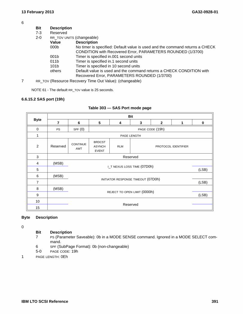
13 February 2013 GA32-0928-01
6Bit Description7-3 Reserved2-0 RR_TOV UNITS (changeable)
Value Description000b No timer is specified: Default value is used and the command returns a CHECK
CONDITION with Recovered Error, PARAMETERS ROUNDED (1/3700)001b Timer is specified in.001 second units011b Timer is specified in.1 second units101b Timer is specified in 10 second unitsothers Default value is used and the command returns a CHECK CONDITION with
Recovered Error, PARAMETERS ROUNDED (1/3700)7 RR_TOV (Resource Recovery Time Out Value): (changeable)
NOTE 61 - The default RR_TOV value is 25 seconds.
6.6.15.2 SAS port (19h)
Byte Description
0Bit Description7 PS (Parameter Saveable): 0b in a MODE SENSE command. Ignored in a MODE SELECT com-
mand.6 SPF (SubPage Format): 0b (non-changeable)5-0 PAGE CODE: 19h
1 PAGE LENGTH: 0Eh
Table 303 — SAS Port mode page
ByteBit
7 6 5 4 3 2 1 0
0 PS SPF (0) PAGE CODE (19h)
1 PAGE LENGTH
2 ReservedCONTINUE
AWT
BRDCST ASYNCH EVENT
RLM PROTOCOL IDENTIFIER
3 Reserved
4 (MSB)I_T NEXUS LOSS TIME (07D0h)
5 (LSB)
6 (MSB)INITIATOR RESPONSE TIMEOUT (07D0h)
7 (LSB)
8 (MSB)REJECT TO OPEN LIMIT (0000h)
9 (LSB)
10Reserved
15
IBM LTO SCSI Reference 391

GA32-0928-01 13 February 2013
2Bit Description7-5 Reserved6 CONTINUE AWT (continue arbitration wait timer): 1b (non-changeble)5 BRDCST ASYNCH EVENT: 0b (non-changeble)4 RLM (Ready LED Meaning): 0b (non-changeble)3-0 PROTOCOL IDENTIFIER: 6h (SAS)
3 Reserved4-5 I_T NEXUS LOSS TIME: 07D0h (non-changeable)6-7 INITIATOR RESPONSE TIMEOUT: 07D0h (non-changeable)8-9 REJECT TO OPEN LIMIT: 0000h (non-changeable)10-15 Reserved
392 IBM LTO SCSI Reference

13 February 2013 GA32-0928-01
6.6.16 MP 1Ah: Power Condition
See MODE SELECT (6/10) - 15h/55h (see 5.2.9 on page 89) for how to set these parameters and MODE SENSE (6/10) - 1Ah/5Ah (see 5.2.10 on page 91) for how to read these parameters.
The power condition mode page controls the timers that the drive uses to go into a low-power mode. If any idle condition timer is enabled, then the low power condition is entered as the result of the expiration of one of the power condition timers in this mode page even if a volume is loaded.
This page is defined as common to all initiators.
Table 304 defines the Power Condition mode page.
Byte Description
0Bit Description7 PS (Parameter Saveable): 0b in a MODE SENSE command. Ignored in a MODE SELECT com-
mand.6 SPF (SubPage Format): 0b5-0 PAGE CODE: 19h
1 PAGE LENGTH: 26h2
Bit Description7-1 Reserved0 STANDBY_Y: 0b (non-changeable)
Table 304 — MP 1Ah: Power Condition mode page format
ByteBit
7 6 5 4 3 2 1 0
0 PS SPF (0b) PAGE CODE (1Ah)
1 PAGE LENGTH (26h)
2 ReservedSTANDBY_Y(0
)
3 Reserved IDLE_C IDLE_B(0) IDLE_A(0)STANDBY_Z(0
)
4 (MSB)IDLE_A CONDITION TIMER (00000000h)
7 (LSB)
8 (MSB)STANDBY_Z CONDITION TIMER (00000000h)
11 (LSB)
12 (MSB)IDLE_B CONDITION TIMER (00000000h)
15 (LSB)
16 (MSB)IDLE_C CONDITION TIMER
19 (LSB)
20 (MSB)STANDBY_Y CONDITION TIMER (00000000h)
23 (LSB)
24 Reserved
39
IBM LTO SCSI Reference 393

GA32-0928-01 13 February 2013
3Bit Description7-4 Reserved3 IDLE_C: 1b (changeable)
Value Description0b The idle_c condition timer is disabled and the power condition is disabled.1b The idle_c condition timer is enabled.
2 IDLE_B: 0b (non-changeable)1 IDLE_A: 0b (non-changeable)0 STANDBY_Z: 0b (non-changeable)
4-7 IDLE_A CONDITION TIMER: 00000000h (non-changeable)8-11 STANDBY_Z CONDITION TIMER: 00000000h (non-changeable)12-15 IDLE_B CONDITION TIMER: 00000000h (non-changeable)16-19 IDLE_C CONDITION TIMER: 00002EE0h (i.e., 20 minutes)(changeable)
Initial value, in 100 millisecond increments, for the idle_c condition timer. This value may be rounded upor down to the nearest implemented time. When in the IDLE_C mode, a REQUEST SENSE commandreturns NO SENSE/IDLE_C CONDITION ACTIVATED BY TIMER (0/5E07).
20-23 STANDBY_Y CONDITION TIMER:00000000h (non-changeable)24-39 Reserved
394 IBM LTO SCSI Reference

13 February 2013 GA32-0928-01
6.6.17 MP 1Ch: Informational Exceptions Control
See MODE SELECT (6/10) - 15h/55h (see 5.2.9 on page 89) for how to set these parameters and MODE SENSE (6/10) - 1Ah/5Ah (see 5.2.10 on page 91) for how to read these parameters.
There is one copy of this page for each initiator.
Byte Description
0Bit Description7 PS (Parameter Saveable): 0b in a MODE SENSE command. Ignored in a MODE SELECT com-
mand.6 SPF (Subpage Format): 0b5-0 PAGE CODE: 1Ch
1 PAGE LENGTH: 0Ah2
Bit Description7 PERF(performance): 0b (non-changeable)6 Reserved5 EBF (enable background function): 0b (non-changeable)4 EWASC (enable warning): 0b (non-changeable)3 DEXCPT (disable exception control): 1b (changeable)
Value Description0b Exception Reporting is enabled1b Exception Reporting is disabled
2 TEST: 0b (changeable)Value Description0b The next command is processed normally (always on Mode Sense)1b The next command will fail with a 6/5DFF (Unit Attention, FAILURE PREDICTION
THRESHOLD EXCEEDED-FALSE).1 EBACKERR (enable background error): 0b (non-changeable)0 LOGERR (log errors): 0b (non-changeable)
3Bit Description7-4 Reserved3-0 MRIE: 3h (non-changeable)
If an exception occurs, the next command will return 1/5D00 (Recovered Error, FAILURE PREDICTION THRESHOLD EXCEEDED).
Table 305 — Informational Exceptions Control mode page
ByteBit
7 6 5 4 3 2 1 0
0 PS SPF (0b) PAGE CODE (1Ch)
1 PAGE LENGTH (0Ah)
2 PERF Reserved EBF EWASC DEXCPT TEST EBACKERR LOGERR
3 Reserved MRIE
4 (MSB)INTERVAL TIMER
7 (LSB)
8 (MSB)REPORT COUNT
11 (LSB)
IBM LTO SCSI Reference 395

GA32-0928-01 13 February 2013
4-7 INTERVAL TIMER: 00000000h (non-changeable)8-11 REPORT COUNT: 00000000h (non-changeable)
396 IBM LTO SCSI Reference

13 February 2013 GA32-0928-01
6.6.18 MP 1Dh: Medium Configuration
See MODE SELECT (6/10) - 15h/55h (see 5.2.9 on page 89) for how to set these parameters and MODE SENSE (6/10) - 1Ah/5Ah (see 5.2.10 on page 91) for how to read these parameters.
The Medium Configuration mode page (see table 306) specifies any special considerations the device server shall use when processing commands that access the medium.
Byte Description
0Bit Description7 PS (Parameter Saveable): 0b in a MODE SENSE command. Ignored in a MODE SELECT com-
mand.6 SPF (Subpage Format): 0b5-0 PAGE CODE: 1Dh
1 PAGE LENGTH: 1Eh2
Bit Description7-1 Reserved0 WORMM(WORM mode): (non-changeable)
Value Description0 The device server is not operating in WORM mode1 The device server is operating in WORM mode
This field is changed by the device and is not allowed to be changed in a MODE SELECT command.
3 Reserved4 WORM MODE LABEL RESTRICTIONS: 01h (non-changeable)
The device allows a tape label to be overwritten. The tape label is defined as 0, 1, or 2 logical blocksfollowed by nothing except 0 to n Filemarks and EOD. This must be overwritten from BOP.
5 WORM MODE FILEMARKS RESTRICTIONS: 02h (non-changeable)The device server shall allow any number of filemarks immediately preceding EOD to be overwrittenexcept the filemark closest to BOP.
6-31 Reserved
Table 306 — Medium Configuration mode page
ByteBit
7 6 5 4 3 2 1 0
0 PS SPF(0) PAGE CODE (1Dh)
1 PAGE LENGTH (1Eh)
2 Reserved WORMM
3 Reserved
4 WORM MODE LABEL RESTRICTIONS
5 WORM MODE FILEMARK RESTRICTIONS
6Reserved
31
IBM LTO SCSI Reference 397

GA32-0928-01 13 February 2013
6.6.19 MP 24h: Vendor-Specific
See MODE SELECT (6/10) - 15h/55h (see 5.2.9 on page 89) for how to set these parameters and MODE SENSE (6/10) - 1Ah/5Ah (see 5.2.10 on page 91) for how to read these parameters.
The Vendor-Specific Speed Matching Control mode page provides control over undocumented test options. Modifying these values could have adverse effects on the drives operation. As such, this page should never be used in a MODE SELECT operation. A MODE SENSE of this page may be used to determine if the drive supports encryption. The Vendor-Specific mode page is defined in table 307.
Byte Description
0Bit Description7 PS (Parameter Saveable): 0b in a MODE SENSE command. Ignored in a MODE SELECT com-
mand.6 SPF (SubPage Format): 0b5-0 PAGE CODE: 24h
1 PAGE LENGTH: 06h2 Vendor-Specific: 3 Vendor-Specific: 4-6 Reserved
Table 307 — Vendor-Specific mode page
ByteBit
7 6 5 4 3 2 1 0
0 PS (0) SPF(0) PAGE CODE (24h)
1 PAGE LENGTH (06h)
2 Vendor-Specific
3 Vendor-Specific
4Reserved
6
7 Reserved ENCR_E Reserved FIPS ENCR_C
398 IBM LTO SCSI Reference

13 February 2013 GA32-0928-01
7Bit Description7-4 Reserved3 ENCR_E (Device Supports Encryption - Enabled) (Changeable-Ignored)
Value Description0b Device does not support encryption1b Device supports encryption (encryption interface(s) are enabled)
NOTE 62 - There are multiple encryption methods, Application Managed Encryption (AME), System Managed Encryption (SME), and Library Managed Encryption (LME). When the drive is configured for SME or LME, encryption is transparent to the application and the SECURITY PROTOCOL IN command reports no encryption support.
2 Vendor-Reserved1 FIPS:
Value Description0b Code is not FIPS level of code1b Code is FIPS level of code
0 ENCR_C (Device Supports Encryption- Capable) (Changeable-Ignored)Value Description0b Device does not support encryption (does not have encryption hardware)1b Device supports encryption (encryption interface(s) are not necessarily enabled)
IBM LTO SCSI Reference 399

GA32-0928-01 13 February 2013
400 IBM LTO SCSI Reference

13 February 2013 GA32-0928-01
This page intentionally left blank
IBM LTO SCSI Reference 401

GA32-0928-01 13 February 2013
402 IBM LTO SCSI Reference

13 February 2013 GA32-0928-01
6.6.20 MP 2Fh: Behavior Configuration
There is one copy of this page for the drive.
Device support for the fields in this page vary by generation and/or code level. To discover if a field can be modified, issue a MODE SENSE with the PC field set to 01b to see if the field is changeable. This will also return the PAGE LENGTH, which must be examined to determined the length of this page, because it is expected to increase as additional Behavior configurations are added to subsequent code levels.
WARNING WARNINGThis page changes the normal behavior of the drive. Some settings effect error reporting and may even cause the drive to violate SCSI standards. Care should be taken to ensure that the behavior change and its effects on
WARNING WARNING
the system are understood.
Byte Description
0Bit Description7 PS (Parameter Saveable): 1b in a MODE SENSE command. Ignored in a MODE SELECT com-
mand.6 SPF (SubPage Format): 0b5-0 PAGE CODE: 2Fh
1 PAGE LENGTH:
Table 308 — Behavior Configuration Mode Page
ByteBit
7 6 5 4 3 2 1 0
0 PS SPF (0b) PAGE CODE (2Fh)
1 PAGE LENGTH (n-1)
2 FENCE BEHAVIOR
3 CLEAN BEHAVIOR
4 WORM BEHAVIOR
5 SENSE DATA BEHAVIOR
6Reporting Behavior
Reserved CCDM DDEOR CLNCHK
7Firmware Update Behavior
Reserved DFMRDL
8Unload On Error Behavior
Reserved UOE-C UOE-F UOE-D
9TapeAlert Behavior
Reserved TA10
…
n Reserved for Future Use
IBM LTO SCSI Reference 403

GA32-0928-01 13 February 2013
2 FENCE BEHAVIOR: 00h (changeable)This field defines drive behavior in situations deemed dangerous for either media or data on the media.Value Description00h Normal operation (i.e., MTR Fence) (see 4.16.5.1.4.1 on page 62)01h Panic Fence operation (see 4.16.5.1.4.2 on page 62)02h-FFh Reserved
3 CLEAN BEHAVIOR: 00h (changeable)Value Description00h Normal Operation01h Periodic Clean Notification
The device monitors criteria since last cleaning. When that criteria is exceeded, the drive puts itself in a clean needed notification state. The criteria used is subject to change. The criteria used at the publication of this document is listed in table 309.
When entering this state the device shall set the Drive Status Flags 1, Byte 7, Bit 6: Drive Clean Required as defined in the LDI and the device shall set TapeAlert flag 21.This device remains in this state until a successful cleaning cycle or a Power On Reset occurs (e.g. If there is another data cartridge inserted without the drive having been cleaned, the drive functions as normal. Once the TapeAlert is reported the first time it will be cleared following normal TapeAlert rules. The Drive Status Flags will function as defined in the LDI.)
02h-FFh Reserved
NOTE 63 - Note: On eServer enabled drives (i.e., The PRODUCT ID returned in Standard Inquiry is "HH LTO Gen x" where "x" is a number) that are attached to AIX, the CLEAN BEHAVIOR gets modified by the SCDD to use Periodic Clean Notification (01h).
4 WORM BEHAVIOR: 00h (changeable)Value Description00h Normal Operation (reset to this value on Medium Removal)01h Data Cartridge Emulates WORM
Treat data cartridge like a WORM cartridge. When a data cartridge is inserted into the drive the drive reports that it is WORM media and the drive behaves like the media is WORM. It follows all overwrite rules. This Emulate mode is cleared when the cartridge is unloaded. There is no emulation of the WORM tampering responses. Sense code of 300Dh is never reported in WORM Emulation mode. WTRE of the Sequential Access Device Configuration Mode page (10h) may be modified but does not affect device behavior in emulation mode.
02h-FFh Reserved5 SENSE DATA BEHAVIOR: 01h (non-changeable)
When the sense data is associated with an Illegal Length read, an 18-byte Request Sense data may beused regardless of the value in this field.Value Description00h Obsolete (Earlier generation devices used this to indicate Sense data was 35-bytes in
length)01h Sense data is 96-bytes in length02h-FFh Reserved
Table 309 — Periodic Clean Notification Criteria
Generation DriveData Sets
Processed
Approximate Equivalent Full
File Passes
Meters of tape pulled across
head
Ultrium 5 HH 5,000,000 8 2,500,000
Ultrium 5 FH 7,500,000 12 3,750,000
404 IBM LTO SCSI Reference

13 February 2013 GA32-0928-01
6 Reporting BehaviorConfigures behaviors related to reporting conditions across the primary interface.Bit Description7-3 Reserved2 CCDM(Check Condition for Dead Media): 0b (changeable)
On eServer enabled drives (i.e., The PRODUCT ID returned in Standard Inquiry is "HH LTO Gen x" where "x" is a number) the default of this field is one.
Value Description0b Does not specify CHECK CONDITION behavior when cleaning is required.1b Return a CHECK CONDITION with Sense Key set to 1h and the additional sense
code set to DEGRADED MEDIA (8252h) after a Rewind command when the cri-teria are met to set the DEAD MEDIA flag in Log Page 3Ch.
1 DDEOR (Disable Deferred Error On Rewind): 0b (changeable)
On eServer enabled drives (i.e., The PRODUCT ID returned in Standard Inquiry is "HH LTO Gen x" where "x" is a number) that are attached to AIX, the DDEOR bit gets set to one by the SCDD.
Value Description0b Deferred error may be reported to a rewind command.1b Deferred error shall not be reported to a rewind command.
0 CLNCHK(Clean Check): 0b (changeable)Value Description0b Does not specify CHECK CONDITION behavior when cleaning is required.1b Return a CHECK CONDITION with Sense Key set to 0h and the additional sense
code set to DRIVE REQUIRES CLEANING (8282h) after a REWIND, SPACE, LOCATE, or UNLOAD when cleaning is required.
7 Firmware Update BehaviorConfigures behaviors related to updating device firmware.Bit Description7-1 Reserved0 DFMRDL (Disable Field Microcode Replacement Down Level): 0b (changeable)
This configures the ability to use an FMR tape to update to a lower level of firmware. This bit does not effect code downloads by means other than an FMR tape (e.g. WRITE BUFFER over SCSI interface).
On eServer enabled drives (i.e., The PRODUCT ID returned in Standard Inquiry is "HH LTO Gen x" where "x" is a number) that are attached to AIX, the DFMRDL bit is set to one by the SCDD.
Value Description0b Device may accept down level firmware by FMR tape.1b Device shall not accept down level firmware by FMR tape.
8 Unload On Error BehaviorConfigures auto unload behaviors of different types of cartridges when the following errors occur:
a) Bad Media causes a mount failure;b) FMR cartridge is loaded when it has not been requested;c) Expired cleaner cartridge is loaded; or
IBM LTO SCSI Reference 405

GA32-0928-01 13 February 2013
d) An invalid or unsupported cleaner cartridge is loaded.Settings specified over a library interface (i.e. LDI or ADI) take precedence over these settings, but donot modify these values.Currently the only values allowed are 00h (no exceptional behavior for any cartridge type) or 15h (do notauto-eject on error for any cartridge type). That is, all fields shall have the same value.Bit Description7-6 Reserved5-4 UOE-C (Unload On Error - Cleaner): 00b (changeable)
Value Description00b No exceptional behavior specified01b Do not auto-eject on error10b-11b Reserved
3-2 UOE-F (Unload on Error - FMR): 00b (changeable)Value Description00b No exceptional behavior specified01b Do not auto-eject on error10b-11b Reserved
1-0 UOE-D (Unload On Error - Data): 00b (changeable)Value Description00b No exceptional behavior specified01b Do not auto-eject on error10b-11b Reserved
9 TapeAlert BehaviorThis field defines unique behaviors for specific TapeAlert flags.Bit Description7-1 Reserved0 TA10: 1b (changeable)
Value Description0b TapeAlert 10h is asserted when a Write, Read, or Verify command is aborted
because the unload button on the panel is pressed1b TapeAlert 10h is asserted when the unload button on the panel is pressed and
the tape is away from BOP (channel LBA != 0); TapeAlert 10h will not be asserted if the tape is at BOP 0 or BOP 1 or if the tape is not threaded.
10-n Future behaviors that may have been defined after publication of this document.
406 IBM LTO SCSI Reference

13 February 2013 GA32-0928-01
6.6.21 MP 30h: Device Attribute Settings
The device attribute settings page and the related subpages are used to query and configure settings used by the drive to control its behavior and configuration in a specified environment. The page_0 mode page 30h is the directory listing of supported subpages. Each subpage is for the query and/or setting of device attributes for a specific function. The persistence of parameters and statement of which parameters are settable or only readable is stated in the section describing each subpage.
See MODE SELECT (6/10) - 15h/55h (see 5.2.9 on page 89) for how to set these parameters and MODE SENSE (6/10) - 1Ah/5Ah (see 5.2.10 on page 91) for how to read these parameters.
6.6.21.1 MP 30h: Directory Listing - Device Attribute Settings
The directory listing - device attribute settings mode page is used to report the list of supported subpages in the device attribute settings mode page and subpages. The page is valid only for a Mode Sense command.
This page is defined as common to all initiators.
The supported subpage list is a list of supported subpages listed in ascending order. Since the list of supported subpages is anticipated to differ between code levels (i.e., newer code levels may add subpages) the complete list is not described here. A user should read this page to determine which subpages may be used.
The following parameters apply:
Byte Description
0Bit Description7 PS (Parameter Saveable): 1b in a MODE SENSE command. Ignored in a MODE SELECT com-
mand.6 SPF (SubPage Format): 0b5-0 PAGE CODE: 30h
1 PAGE LENGTH: 2-n Supported subpage list: Supported subpage list - Device Attribute Settings (see 6.6.21.2 on page 408)
describes the subpages that were implemented or planned at the time this document was published.
Table 310 — MP 30h: Directory Listing - Device Attribute Settings mode page format
ByteBit
7 msb 6 5 4 3 2 1 0 lsb
0 PS SPF(0) PAGE CODE (30h)
1 PAGE LENGTH (n-1)
Supported subpage list
2 Supported subpage [first]…
n Supported subpage [last]
IBM LTO SCSI Reference 407

GA32-0928-01 13 February 2013
6.6.21.2 Supported subpage list - Device Attribute Settings
The supported subpage list returns the list of supported subpages. These subpages are organized in logical groupings by function.
Range Description01h-03h MP 30h[01h-03h]: Ethernet attributes - Device attribute settings (see 6.6.21.3 on
page 409).04h-1Fh Reserved20h MP 30h[20h-(20h)]: Encryption Attributes - Device Attribute Settings (see 6.6.21.4 on
page 417).21h-3Fh Reserved40h-42h MP 30h[40h-42h]: Data processing attributes - Device attribute settings (see 6.6.21.5 on
page 418)43h-FEh Reserved
The list of subpages that were implemented or planned at the time this document was published follows:
MP 30h[01h]: Drive MAC address - Device attribute settings (see 6.6.21.3.2 on page 412)MP 30h[02h]: Drive IP address and subnet mask - Device attribute settings (see 6.6.21.3.3 on page 414)MP 30h[03h]: Key manager IP address information - Device attribute settings (see 6.6.21.3.4 on page 416)MP 30h[20h]: Encryption mode - Device Attribute Settings (see 6.6.21.4.1 on page 417)MP 30h[40h]: SkipSync - Device attribute settings (see 6.6.21.5.1 on page 418)MP 30h[42h]: End of partition behavior control - Device attribute settings (see 6.6.21.5.3 on page 422)
Byte Description
2 First subpage: 01h3 Second subpage: 02h4 Third subpage: 03h5 Fourth subpage: 20h6 Fifth subpage: 40h7 Sixth subpage: 41h8 Seventh subpage: 42h
408 IBM LTO SCSI Reference

13 February 2013 GA32-0928-01
6.6.21.3 MP 30h[01h-03h]: Ethernet attributes - Device attribute settings
6.6.21.3.1 Ethernet attributes overview
The Ethernet attributes subpages of the device attribute mode page describe information related to the drives Ethernet interface. The subclauses to this subclause list structures used by the Ethernet attribute subpages that are described in the subclauses that are at a peer level to this subclause.
6.6.21.3.1.1 Ethernet socket address descriptor
The IP address and subnet mask is defined in table 311..
The following parameters apply:
Byte Description
0-1 ETHERNET SOCKET ADDRESS DESCRIPTOR LENGTH - The number of bytes to follow in the Ethernet socketaddress descriptor.
2-3 RELATIVE SOCKET ADDRESS IDENTIFIER - A unique identifier for this Ethernet socket address.4-31 SOCKADDR - defined by type of IP address
Type DescriptionIPv4 6.6.21.3.1.1.1IPv6 6.6.21.3.1.1.2
32 SUBNET MASK LENGTH - The number of bits set to one in the subnet mask.33-35 Reserved
Table 311 — Ethernet socket address descriptor
ByteBit
7 6 5 4 3 2 1 0
0 MSBethernet socket address descriptor length (22h)
1 LSB
2 MSBrelative socket address identifier
3 LSB
4sockaddr
31
32 subnet mask length
33Reserved
35
IBM LTO SCSI Reference 409

GA32-0928-01 13 February 2013
6.6.21.3.1.1.1 Sockaddr for an IPv4 IP address
The sockaddr for an IPv4 IP address is defined in table 312.
The following parameters apply:
Byte Description
0 ADDRESS LENGTH (10h)1 ADDRESS FAMILY (02h)2-3 PORT - The TCP port number, if any. Zero if there is no TCP port number.4-7 INTERNET ADDRESS - The IP Address.8-27 Pad bytes - All bytes set to zero.
6.6.21.3.1.1.2 Sockaddr for an IPv6 address
The sockaddr for an IPv6 IP address is defined in table 313.
Table 312 — Sockaddr format for IPv4
ByteBit
7 6 5 4 3 2 1 0
0 address length
1 address family
2 MSBport
3 LSB
4 MSBinternet address
7 LSB
8Pad bytes
27
Table 313 — Sockaddr format for IPv6
ByteBit
7 6 5 4 3 2 1 0
0 address length
1 address family
2 MSBport
3 LSB
4flow info
7
8 MSBinternet address
23 LSB
24scope id
27
410 IBM LTO SCSI Reference

13 February 2013 GA32-0928-01
The following parameters apply:
Byte Description
0 ADDRESS LENGTH (1Ch)1 ADDRESS FAMILY (0Ah)2-3 PORT - The TCP port number, if any. Zero if there is no TCP port number.4-7 FLOW INFO - (0000 0000h)8-23 INTERNET ADDRESS - The IP Address.24-27 SCOPE ID - (0000 0000h)
IBM LTO SCSI Reference 411

GA32-0928-01 13 February 2013
6.6.21.3.2 MP 30h[01h]: Drive MAC address - Device attribute settings
The drive MAC address is read only and is defined in table 314.
The following parameters apply:
Byte Description
0Bit Description7 PS (Parameter Saveable): 0b in a MODE SENSE command. Ignored in a MODE SELECT com-
mand.6 SPF (1b)5-0 PAGE CODE (30h)
1 SUBPAGE CODE (01h)2-3 PAGE LENGTH
4-6 Reserved7 NUMBER OF DRIVE PORT MAC ADDRESS DESCRIPTORS - The number of descriptors to follow
Table 314 — Drive MAC address
ByteBit
7 6 5 4 3 2 1 0
0 ps (0b) spf(1b) PAGE CODE (30h)
1 SUBPAGE CODE (01h)
2 (MSB)PAGE LENGTH (n-3)
3 (LSB)
4 Reserved
5 Reserved
6 Reserved
7 number of drive port mac address descriptors
8 Drive port MAC address descriptor [first]
15
…
n-7 Drive port MAC address descriptor [last]
n
412 IBM LTO SCSI Reference

13 February 2013 GA32-0928-01
8-n Drive port MAC address descriptors.The Drive port MAC address descriptors are listed in ascending order by RELATIVE TARGET PORT
IDENTIFIER. The Drive port MAC address descriptor is defined in table 315.
Byte Description
0-1 RELATIVE TARGET PORT IDENTIFIER - The relative port value for the Ethernet port.2-7 MAC ADDRESS - The binary representation of the MAC address for that port.
Table 315 — Drive port MAC address descriptor
ByteBit
7 6 5 4 3 2 1 0
0 MSBrelative target port identifier
1 LSB
2mac address
7
IBM LTO SCSI Reference 413

GA32-0928-01 13 February 2013
6.6.21.3.3 MP 30h[02h]: Drive IP address and subnet mask - Device attribute settings
The drive IP address and subnet mask subpage is defined in table 316. When sending the drive IP address and subnet mask subpage in a Mode Select command the SP bit shall be set to one. If the SP bit is set to zero, then the drive rejects the command with a CHECK CONDITION and sets the sense key to ILLEGAL REQUEST and the additional sense code to INVALID FIELD IN CDB.
The following parameters apply:
Byte Description
0Bit Description7 PS (Parameter Saveable): 1b in a MODE SENSE command. Ignored in a MODE SELECT com-
mand.6 SPF (1b)5-0 PAGE CODE (30h)
1 SUBPAGE CODE (02h)2-3 PAGE LENGTH
4-5 Reserved6 Restricted7 NUMBER OF DRIVE PORT DESCRIPTORS - May be set to any number between one and the number of drive
Ethernet ports inclusive. Changes will only affect the ports for which a drive Ethernet port descriptor issent.
Table 316 — Drive IP address and subnet mask subpage
ByteBit
7 6 5 4 3 2 1 0
0 ps spf(1b) PAGE CODE (30h)
1 SUBPAGE CODE (02h)
2 (MSB)PAGE LENGTH (n-3)
3 (LSB)
4 Reserved
5 Reserved
6 Restricted
7 number of drive ethernet port descriptors
8Drive Ethernet port descriptor [first]
m
…
n-kDrive Ethernet port descriptor [last]
n
414 IBM LTO SCSI Reference

13 February 2013 GA32-0928-01
8-n Drive Ethernet port descriptors.The drive Ethernet port descriptors shall be sent in ascending order by RELATIVE TARGET PORT IDENTIFIER
(see table 317). The drive Ethernet port descriptor is defined in table 317.
Byte Description
0-1 DRIVE ETHERNET PORT DESCRIPTOR LENGTH - The number of bytes to follow in the drive Ethernet portdescriptor.
2-3 RELATIVE TARGET PORT IDENTIFIER - The relative port identifier of the Ethernet port.4-5 Reserved6
Bit Description7-1 Reserved0 DHCP_V4
Value Description1b DHCP shall be used to obtain an additional IPv4 address.0b DHCP shall not be used to obtain an additional IPv4 address.
7 NUMBER OF ETHERNET SOCKET ADDRESS DESCRIPTORS - Shall be set to 01h or 02h.8-n Ethernet socket address descriptors. The Ethernet socket address descriptor is defined in 6.6.21.3.1.1
on page 409.In each Ethernet socket address descriptor the PORT field of the SOCKADDR (see table 312 and table 313)is reserved and shall be set to zero.In each Ethernet socket address descriptor the FLOW INFO field of the SOCKADDR (see table 313), if any, isreserved and shall be set to zero.In each Ethernet socket address descriptor the SCOPE ID field of the SOCKADDR (see table 313), if any, isreserved and shall be set to zero.
Table 317 — Drive Ethernet port descriptor
ByteBit
7 6 5 4 3 2 1 0
0 MSBdrive ethernet port descriptor length (n-1)
1 LSB
2 MSBrelative target port identifier
3 LSB
4Reserved
5
6 Reserved dhcp_v4
7 number of ethernet socket address descriptors
8Ethernet socket address descriptor [first]
x
…
yEthernet socket address descriptor [last]
n
IBM LTO SCSI Reference 415

GA32-0928-01 13 February 2013
6.6.21.3.4 MP 30h[03h]: Key manager IP address information - Device attribute settings
The Key manager IP address information descriptor is defined in table 318. When sending the key manager IP address information subpage in a Mode Select command the SP bit shall be set to one. If the SP bit is set to zero, then the drive rejects the command with a CHECK CONDITION and sets the sense key to ILLEGAL REQUEST and the additional sense code to INVALID FIELD IN CDB.
The following parameters apply:
Byte Description
0Bit Description7 PS (Parameter Saveable): 1b in a MODE SENSE command. Ignored in a MODE SELECT com-
mand.6 SPF (1b)5-0 PAGE CODE (30h)
1 SUBPAGE CODE (03h)2-3 PAGE LENGTH
4-6 Reserved7 NUMBER OF ETHERNET SOCKET ADDRESS DESCRIPTORS - Shall be set to 01h or 02h.8-n Ethernet socket address descriptors. The Ethernet socket address descriptor is defined in 6.6.21.3.1.1
on page 409.In each Ethernet socket address descriptor the SUBNET MASK LENGTH field (see table 311) is reserved andshall be set to zero.In each Ethernet socket address descriptor the FLOW INFO field of the SOCKADDR (see table 313), if any, isreserved and shall be set to zero.In each Ethernet socket address descriptor the SCOPE ID field of the SOCKADDR (see table 313), if any, isreserved and shall be set to zero.
Table 318 — Key manager IP address information
ByteBit
7 6 5 4 3 2 1 0
0 ps spf(1b) PAGE CODE (30h)
1 SUBPAGE CODE (03h)
2 (MSB)PAGE LENGTH (n-3)
3 (LSB)
4 Reserved
5 Reserved
6 Reserved
7 NUMBER OF ETHERNET SOCKET ADDRESS DESCRIPTORS
8Ethernet socket address descriptor [first]
x
…
yEthernet socket address descriptor [last]
n
416 IBM LTO SCSI Reference

13 February 2013 GA32-0928-01
6.6.21.4 MP 30h[20h-(20h)]: Encryption Attributes - Device Attribute Settings
6.6.21.4.1 MP 30h[20h]: Encryption mode - Device Attribute Settings
The Encryption mode - Device attribute settings mode page allows an application client to query the encryption settings in the drive. If the drive receives an encryption mode - device attribute settings mode page in a Mode Select command it shall reject the command with an ILLEGAL REQUEST, INVALID FIELD IN PARAMETER LIST. The encryption mode - Device attribute settings mode page is defined in table 319.
The PS bit is set to 0b on a Mode Sense Command indicating that the parameters are not saveable via a Mode Select. The PS bit is ignored on MODE SELECT. Note that the parameters do change in response to configuration changes made via other paths (e.g., through the library).
The Encryption mode - Device attribute settings mode page is not allowed in a Mode Select command.The Encryption mode - Device attribute settings mode page may be used in a Mode Sense command to query the current Encryption settings. Some of the settings likely to be reported are listed in table 320.
Table 319 — Encryption mode mode page
ByteBit
7 6 5 4 3 2 1 0
0 ps spf(1b) Page Code (30h)
1 Subpage Code (20h)
2 (MSB)Page Length (0005h)
3 (LSB)
4 Reserved
5 Encryption Solution Method
6 Key Path
7 Default Encryption State
8 Density Reporting
Table 320 — Expected Encryption settings
Encryption settingMethod(byte 5)
Key Path(byte 6)
DefaultEncryption
State(byte 7)
DensityReporting
(byte 8)
No Encryption 01h 01h 01h 00h
AME (Application Managed Encryption) 03h 01h 01h 00h
LME (Library Managed Encryption) - Barcode policy 04h 01h 03h 00h
LME - Internal label (selects) policy 04h 01h 06h 00h
LME - Internal label (all) policy 04h 01h 07h 00h
LME - Encrypt Always policy 04h 01h 02h 00h
Custom combinations not listed above
IBM LTO SCSI Reference 417

GA32-0928-01 13 February 2013
6.6.21.5 MP 30h[40h-42h]: Data processing attributes - Device attribute settings
6.6.21.5.1 MP 30h[40h]: SkipSync - Device attribute settings
See MODE SELECT (6/10) - 15h/55h (see 5.2.9) for how to set these parameters and MODE SENSE (6/10) - 1Ah/5Ah (see 5.2.10) for how to read these parameters.
This page is defined as common to all initiators.
The SkipSync mode page is defined in table 314. SkipSync is a feature that performs a trade-off between howmuch data can be written to a volume and how fast that data can be written when the data is a small file size.This mode page allows the feature to be enabled and disabled. It also provides information that describes certainaspects of this trade-off, such as the Target Minimum Capacity. This feature is only available for use on volumesthat are not scaled and that are not partitioned. The volume must be an Ultrium 5 or newer cartridge.
Byte Description
0Bit Description7 PS (Parameter Saveable): 1b in a MODE SENSE command. Ignored in a MODE SELECT com-
mand.
It is recommended that users set the SP bit of the MODE SELECT command to one.
6 SPF (SubPage Format): 1b5-0 PAGE CODE: 01h
1 SUBPAGE CODE: 40h2-3 PAGE LENGTH: 10h
Table 321 — SkipSync - Device attribute settings mode page format
BitByte
7 6 5 4 3 2 1 0
0 PS SPF(1b) PAGE CODE (30h)
1 SUBPAGE CODE (40h)
2 (MSB)PAGE LENGTH 10h
3 (LSB)
4 Reserved SV ENABLE
5 Reserved
6 Reserved
7 SKIPSYNC POLICY
8 (MSB) TARGET MINIMUM CAPACITY
11 (LSB)
12 (MSB)Vendor-restricted
15 (LSB)
16 (MSB)Vendor-restricted
19 (LSB)
418 IBM LTO SCSI Reference
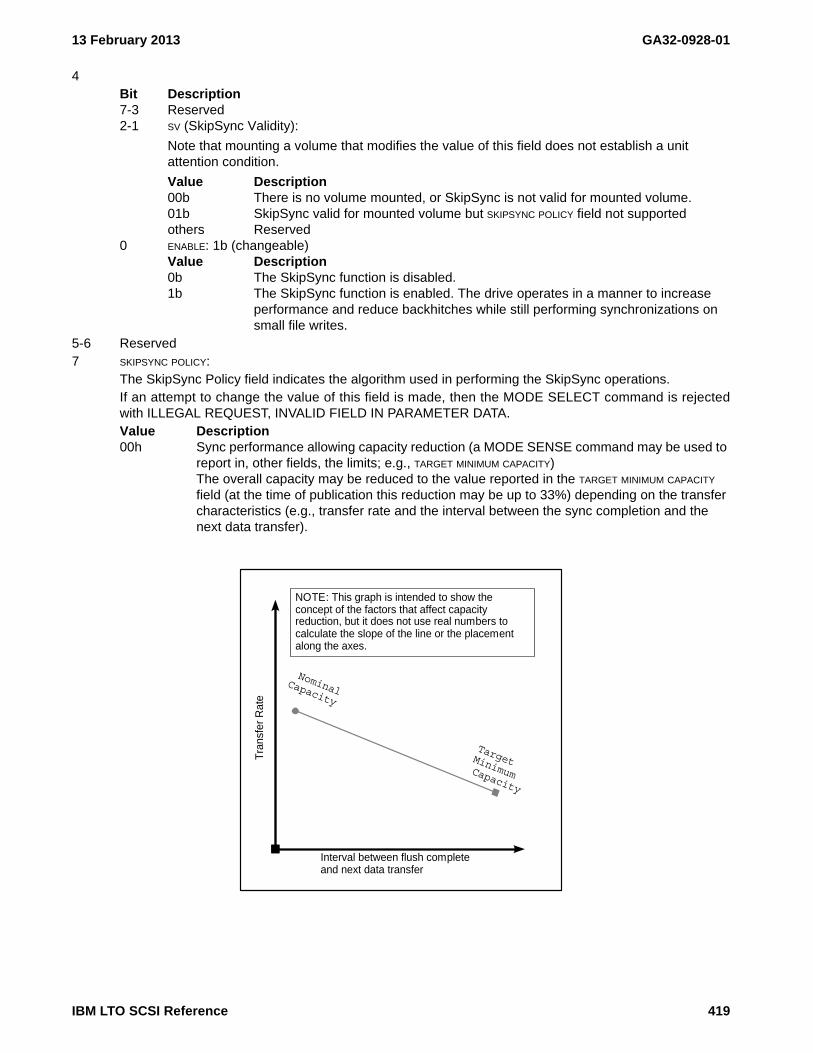
13 February 2013 GA32-0928-01
4Bit Description7-3 Reserved2-1 SV (SkipSync Validity):
Note that mounting a volume that modifies the value of this field does not establish a unit attention condition.
Value Description00b There is no volume mounted, or SkipSync is not valid for mounted volume.01b SkipSync valid for mounted volume but SKIPSYNC POLICY field not supportedothers Reserved
0 ENABLE: 1b (changeable)Value Description0b The SkipSync function is disabled.1b The SkipSync function is enabled. The drive operates in a manner to increase
performance and reduce backhitches while still performing synchronizations on small file writes.
5-6 Reserved7 SKIPSYNC POLICY:
The SkipSync Policy field indicates the algorithm used in performing the SkipSync operations.If an attempt to change the value of this field is made, then the MODE SELECT command is rejectedwith ILLEGAL REQUEST, INVALID FIELD IN PARAMETER DATA.Value Description00h Sync performance allowing capacity reduction (a MODE SENSE command may be used to
report in, other fields, the limits; e.g., TARGET MINIMUM CAPACITY)The overall capacity may be reduced to the value reported in the TARGET MINIMUM CAPACITY field (at the time of publication this reduction may be up to 33%) depending on the transfer characteristics (e.g., transfer rate and the interval between the sync completion and the next data transfer).
Interval between flush completeand next data transfer
Tra
nsfe
r R
ate
Nominal Target
Capacity Minimum
Capacity
NOTE: This graph is intended to show the concept of the factors that affect capacity reduction, but it does not use real numbers to calculate the slope of the line or the placement along the axes.
IBM LTO SCSI Reference 419

GA32-0928-01 13 February 2013
8-11 TARGET MINIMUM CAPACITY (MiB): (non-changeable) (ignored on MODE SELECT)This field indicates the target capacity in mebibytes (220) to which the capacity of the current partitionwhen full may be decreased in order to perform SkipSync operations. The total capacity may be smallerthan TARGET MINIMUM CAPACITY if the average of transaction sizes is very small. If the mounted volume is not capable of supporting skipsync this field is set to zero.
12-15 Vendor-restricted16-19 Vendor-restricted
420 IBM LTO SCSI Reference

13 February 2013 GA32-0928-01
6.6.21.5.2 MP 30h[41h]: Tape map control - Device attribute settings
The Tape map control - Device attribute settings mode page is not intended for general use.
IBM LTO SCSI Reference 421
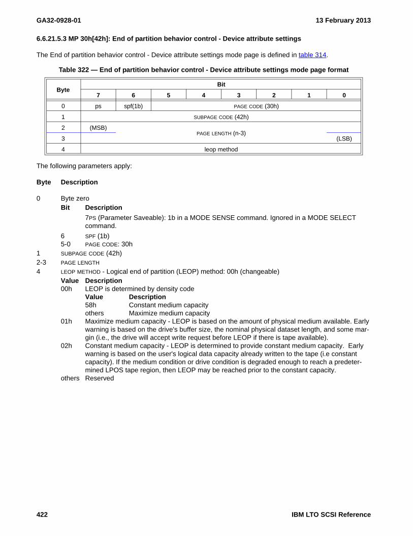
GA32-0928-01 13 February 2013
6.6.21.5.3 MP 30h[42h]: End of partition behavior control - Device attribute settings
The End of partition behavior control - Device attribute settings mode page is defined in table 314.
The following parameters apply:
Byte Description
0 Byte zeroBit Description
7PS (Parameter Saveable): 1b in a MODE SENSE command. Ignored in a MODE SELECT command.
6 SPF (1b)5-0 PAGE CODE: 30h
1 SUBPAGE CODE (42h)2-3 PAGE LENGTH
4 LEOP METHOD - Logical end of partition (LEOP) method: 00h (changeable)Value Description00h LEOP is determined by density code
Value Description58h Constant medium capacityothers Maximize medium capacity
01h Maximize medium capacity - LEOP is based on the amount of physical medium available. Early warning is based on the drive's buffer size, the nominal physical dataset length, and some mar-gin (i.e., the drive will accept write request before LEOP if there is tape available).
02h Constant medium capacity - LEOP is determined to provide constant medium capacity. Early warning is based on the user's logical data capacity already written to the tape (i.e constant capacity). If the medium condition or drive condition is degraded enough to reach a predeter-mined LPOS tape region, then LEOP may be reached prior to the constant capacity.
others Reserved
Table 322 — End of partition behavior control - Device attribute settings mode page format
ByteBit
7 6 5 4 3 2 1 0
0 ps spf(1b) PAGE CODE (30h)
1 SUBPAGE CODE (42h)
2 (MSB)PAGE LENGTH (n-3)
3 (LSB)
4 leop method
422 IBM LTO SCSI Reference

13 February 2013 GA32-0928-01
6.6.22 MP 3Eh: Engineering Support
See MODE SELECT (6/10) - 15h/55h (see 5.2.9 on page 89) for how to set these parameters and MODE SENSE (6/10) - 1Ah/5Ah (see 5.2.10 on page 91) for how to read these parameters.
The initiator behavior for this page is not defined, and may contain elements which are common to all initiators, as well as elements which are initiator unique.
NOTE 64 - As this page is not for normal application use, it is not returned in mode page 3Fh (all pages). Conse-quently, this page must be specifically queried and set.
NOTE 65 - For more information on special needs and the usage of this page contact IBM.
Byte Description
0Bit Description7 PS (Parameter Saveable): 0b in a MODE SENSE command. Ignored in a MODE SELECT com-
mand.6 SPF (SubPage Format): 0b5-0 PAGE CODE: 3Eh
1 PAGE LENGTH: 7Eh2-127 Vendor-Reserved
Table 323 — MP 3Eh: Engineering Support mode page
ByteBit
7 6 5 4 3 2 1 0
0 PS SPF (0b) PAGE CODE (3Eh)
1 PAGE LENGTH (n-1)
2Vendor-reserved
127
IBM LTO SCSI Reference 423

GA32-0928-01 13 February 2013
424 IBM LTO SCSI Reference

13 February 2013 GA32-0928-01
6.7 Read/Write Buffers (RB)
Read/Write Buffers are used with the READ BUFFER command (see 5.2.17) and/or the WRITE BUFFER command (see 5.2.41).
6.7.1 Supported Buffers for modes other than 1Ch
Table 324 lists the supported buffers and their IDs for modes other than 1Ch. MODE[1Ch] – Error history (see 5.2.17.7 on page 113) describes the supported buffers when the MODE field is set to 1Ch.
Table 324 — Supported Buffer IDs
ID a R/W Buffer Description Offset Boundary
00h R Format Buffer b (Main Data) 4
01h R Dump Data c d 4
02h R/W Test 4
03h R/W VPD 4
04h R/W Firmware 4
05h R Cartridge Memory 4
06h R Error Log 4
07h R SCSI Log 4
08h R WWN 4
50h R Active IP addresses TBD
20h R Cartridge Memory (same as Buffer ID 05h) 4
21h e R Cartridge Memory from EOD dataset 4
LegendR Read OnlyW Write OnlyR/W Read/Write- Not ApplicableNS Not Supported
Notesa In a WRITE BUFFER command, if the MODE field is 04h, 05h, 06h or 07h, then the BUFFER ID is ignored and the
command is treated as a Firmware buffer (i.e., BUFFER ID 04h).b MODE[07h] – Descriptor with algorithmic offset boundary (see 5.2.17.4 on page 112) describes how to interpret
the OFFSET BOUNDARY and BUFFER OFFSET fields for buffers that are too large to use the OFFSET BOUNDARY and BUFFER OFFSET fields such as the Format buffer (i.e., BUFFER ID 00h). This interpretation for the Format buffer is only valid for buffer modes 00h, 01h, 02h, 03h, and 07h.
c When reading dump data, take care to ensure that the amount of data in each transfer does not exceed the DMA settings of the HBA. The dump data currently exceeds 1 MiB in size. The default DMA setting for some HBAs is 1 MiB. For this reason, it is recommended that the dump data is read in a series of smaller blocks with appropriate offsets (for example, 256 KiB).
d When reading dump data the data should be read with strictly increasing offsets.e The volume must be positioned at the EOD from which the CM contents will be read (e.g., issue LOCATE to
desired partition then issue SPACE EOD then issue the READ BUFFER command). If the medium is not positioned at EOP, then the Read Buffer command is rejected with CHECK CONDITION status and Sense Key set to ILLEAGAL REQUEST with the additional sense code set to SEQUENTIAL POSITIONING ERROR. If the medium is positioned at EOP and the EOD cannot be found the READ BUFFER command is rejected with CHECK CONDITION status and Sense Key set to MEDIUM ERROR with the additional sense code set to END-OF-DATA NOT FOUND.
IBM LTO SCSI Reference 425

GA32-0928-01 13 February 2013
6.7.2 RB 06h: Error Log
The error log buffer (also known as Engineering Log) contains zero or more entries described in table 325. Entries are returned in order by the most recent entry first.
The following parameters apply to the Error Log Buffer:
Byte Description
0-3 TIME STAMP: The value of the drive's timestamp at the time of the error. This timestamp may be thepower-on seconds or it may be the value of the timestamp as set by the library or the host. It is generallynot sufficient on its own to provide relative ordering of the entries.
4 ENTRY NUMBER: This is a value used internally to the drive.5 ERROR CODE: The error code used for the Single Character Display.6-7 FSC 1ST TEXT: Fault Symptom Code text8-9 FSC 1ST DATA: Fault Symptom Code data10-11 FSC 2ND TEXT: Fault Symptom Code text12-13 FSC 2ND DATA: Fault Symptom Code data14-21 CARTRIDGE SERIAL NUMBER: This is the cartridge serial number of the volume that was mounted in the
drive when the error occurred. The cartridge serial number is set using this priority:1) Volume Serial Number set by library;2) Volume Serial Number set by host; then3) Cartridge Serial Number from Cartridge Memory.
22-27 LINK LEVEL: The link level of the code that was loaded in the drive when the error occurred.28-31 HARDWARE LEVEL: Not used.
Table 325 — Error Log Buffer (06h)
ByteBit
7 6 5 4 3 2 1 0
0 (MSB)TIME STAMP
3 (LSB)
4 ENTRY NUMBER
5 ERROR CODE
6FSC 1ST TEXT
7
8FSC 1ST DATA
9
10FSC 2ND TEXT
11
12FSC 2ND DATA
13
14CARTRIDGE SERIAL NUMBER
21
22LINK LEVEL
27
28HARDWARE LEVEL
31
426 IBM LTO SCSI Reference

13 February 2013 GA32-0928-01
6.7.3 RB 08h: World Wide Name
This buffer contains the World Wide Name values that are used by the drive.
The following parameters apply:
Byte Description
0-7 WORLD WIDE NODE NAME: The world wide identifier used by the drive to identify LUN 0.8-15 WORLD WODE PORT NAME: The world wide identifier used by the drive port through which the READ
BUFFER command was recevied.
Table 326 — World Wide Name Buffer (08h)
ByteBit
7 6 5 4 3 2 1 0
0 (MSB)WORLD WIDE NODE NAME
7 (LSB)
8 (MSB)WORLD WIDE PORT NAME
15 (LSB)
IBM LTO SCSI Reference 427

GA32-0928-01 13 February 2013
6.7.4 RB 07h: SCSI Log (aka Error log)
The SCSI Log Buffer contains 10 entries, each of which has the format described in table 327. An entry is created each time sense data with a Sense Key 3h or 4h is returned with a CHECK CONDITION Status to a command that is received on LUN 0.
The following parameters apply:
Byte Description
0-3 TIME STAMP: The time stamp in seconds when the entry was created.4 ENTRY NUMBER: A value of 0 indicates that the entry is not valid. The scheme used for setting the Entry
Number is not described in this manual.5 INITIATOR SCSI ID: The least significant byte of the address used to identify the initiator (e.g., on Fibre
Channel drives the ALPA)6 SCSI STATUS: The value that would be returned as SCSI Status.7 Reserved8-23 CDB: The contents of the CDB that was presented the CHECK CONDITION Status even if that CHECK
CONDITION is for a DEFERRED ERROR.24-59 SENSE DATA: The sense data that was created as a result of this error.
Table 327 — SCSI Log Buffer (07h)
ByteBit
7 6 5 4 3 2 1 0
0 (MSB)TIME STAMP (seconds)
3 (LSB)
4 ENTRY NUMBER
5 INITIATOR SCSI ID
6 SCSI STATUS
7 Reserved
8CDB
23
24SENSE DATA
59
428 IBM LTO SCSI Reference

13 February 2013 GA32-0928-01
6.7.5 RB 50h: Active IP addresses
The Active IP addresses buffer returns a list of IP addresses that have successfully completed negotiation on the Ethernet link and are active. This list does not contain IP addresses that the drive attempts but cannot use due to conflicts or other errors. The format of the Data field of the active IP addresses buffer depends on the value in byte 0. If byte 0 contains a non-zero value, then the format is defined in Active IP addresses fixed buffer (see 6.7.5.1). If byte 0 contains a zero value, then the format is defined in the Active IP addresses variable buffer (see 6.7.5.2).
6.7.5.1 Active IP addresses fixed buffer
The format of the Data field of the active IP addresses fixed buffer is described in table 328
.
The following parameters apply:
Byte Description
0 NUMBER OF ETHERNET PORTS - The number of physical Ethernet ports functioning in the drive.1-n List of Ethernet port descriptors. There will be one Ethernet port descriptor (see table 329) for each
physical Ethernet port functioning in the drive. The size of each descriptor may vary from Ethernet port toEthernet port.
The Ethernet port descriptor format is defined in table 329
Table 328 — Active IP addresses fixed buffer format
ByteBit
7 6 5 4 3 2 1 0
0 NUMBER OF ETHERNET PORTS
List of Ethernet port descriptors
1Ethernet port fixed descriptor [first]
x
…
yEthernet port fixed descriptor [last]
n
Table 329 — Ethernet port fixed descriptor format
ByteBit
7 6 5 4 3 2 1 0
0 SIZE OF SOCKADDR (m-1)
1 NUMBER OF SOCKADDR STRUCTURES
List of sockaddr structures (see 6.6.21.3.1.1.1 or 6.6.21.3.1.1.2)
2sockaddr [first]
m
…
n-msockaddr [last]
n
IBM LTO SCSI Reference 429

GA32-0928-01 13 February 2013
The following parameters apply:
Byte Description
0 SIZE OF SACKADDR - The size of each sockaddr. All sockaddr’s are the same size1 NUMBER OF SOCKADDR - The number of sockaddr structures returned.2-n List of sockaddr structures. Each sockaddr structure describes one active IP address. The sockaddr
structure is defined in clauses Sockaddr for an IPv4 IP address (see 6.6.21.3.1.1.1 on page 410) andSockaddr for an IPv6 address (see 6.6.21.3.1.1.2 on page 410).
6.7.5.2 Active IP addresses variable buffer
The format of the Data field of the active IP addresses buffer is described in table 328
.
The following parameters apply:
Byte Description
0 NUMBER OF ETHERNET PORTS - The number of physical Ethernet ports functioning in the drive.1-n List of Ethernet port descriptors. There will be one Ethernet port descriptor (see table 331) for each
physical Ethernet port functioning in the drive. The size of each descriptor may vary from Ethernet port toEthernet port.
Table 330 — Active IP addresses variable buffer format
ByteBit
7 6 5 4 3 2 1 0
0Reserved
1
2ACTIVE IP ADDRESSES BUFFER LENGTH (n-3)
3
4Reserved
6
7 NUMBER OF ETHERNET PORTS
List of Ethernet port descriptors
8Ethernet port variable descriptor [first]
…
Ethernet port variable descriptor [last]n
430 IBM LTO SCSI Reference

13 February 2013 GA32-0928-01
The Ethernet port variable descriptor format is defined in table 331
The following parameters apply:
Byte Description
0 SIZE OF SACKADDR - The size of each sockaddr. All sockaddr’s are the same size1 number of sockaddr - The number of sockaddr structures returned.2-n List of Ethernet socket address descriptors. Each Ethernet socket address descriptor describes one
active IP address and has the RELATIVE SOCKET ADDRESS IDENTIFIER field set to zero. The Ethernet socketaddress descriptor is defined in Ethernet socket address descriptor (see 6.6.21.3.1.1 on page 409).
Table 331 — Ethernet port variable descriptor format
ByteBit
7 6 5 4 3 2 1 0
0DESCRIPTOR LENGTH (m-1)
1
2PORT IDENTIFIEr
3
4Reserved
6
7 NUMBER OF SOCKADDR STRUCTURES
List of Ethernet socket address descriptors (see 6.6.21.3.1.1)
8Ethernet socket address descriptor [first]
…
Ethernet socket address descriptor [last]m
IBM LTO SCSI Reference 431

GA32-0928-01 13 February 2013
432 IBM LTO SCSI Reference

13 February 2013 GA32-0928-01
6.8 Security Protocol Parameters (SPP)
Security Protocol parameters are used by the SECURITY PROTOCOL IN (SPIN) - A2h (see 5.2.30 on page 161)command and by the SECURITY PROTOCOL OUT (SPOUT) - B5h (see 5.2.31 on page 162) command.
The following terms are used in this clause:
Term DescriptionSPIN Security Protocol InSPOUT Security Protocol Out
6.8.1 SPIN Pages (00h - Security Protocol Information)
See SECURITY PROTOCOL IN (SPIN) - A2h (see 5.2.30 on page 161) for a description of how to request this page. The Security Protocol Specific field of the SPIN CDB is defined by Table 332
Table 332 — Security Protocol Specific Definitions for Security Protocol 00h
Code Description Reference
0000h Supported security protocol list see page 434
0001h Certificate data see page 435
0002h - FFFFh Reserved
IBM LTO SCSI Reference 433

GA32-0928-01 13 February 2013
6.8.1.1 SPIN (00h[0000h]) - Supported Security Protocols List
See SECURITY PROTOCOL IN (SPIN) - A2h (see 5.2.30 on page 161) for a description of how to request this page. If the SECURITY PROTOCOL field is set to 00h and the SECURITY PROTOCOL SPECIFIC field is set to 0000h in a SECURITY PROTOCOL IN command, the parameter data shall have the format shown in Table 333.
The Supported Security Protocol list contains the following supported security protocols:
Value Description00h Security protocol information (see 6.8.1).20h Tape Data Encryption (see 6.8.2).
Table 333 — Supported Security Protocols List Structure
ByteBit
7 msb 6 5 4 3 2 1 0 lsb
0Reserved
5
6 (MSB)SUPPORTED SECURITY PROTOCOL LIST LENGTH (m-7)
7 (LSB)
8 Supported Security Protocol (first)
…
m Supported Security Protocol (last)
434 IBM LTO SCSI Reference

13 February 2013 GA32-0928-01
6.8.1.2 SPIN (00h[0001h]) - Certificate Data
See SECURITY PROTOCOL IN (SPIN) - A2h (see 5.2.30 on page 161) for a description of how to request this page. The drive certificate (if present) is provided in X.509 format via this interface (see SPC-4).
If the Security Protocol field is set to 00h and the Security Protocol Specific field is set to 0001h in a Security Protocol In command, the parameter data shall have the format shown in Table 334.
The following parameters apply:
• Certificate Length - The total length, in bytes, of the certificate that follows.
• Certificate - The drive certificate set during manufacturing is returned.
Table 334 — 0001h - Certificate Data Structure
ByteBit
7 msb 6 5 4 3 2 1 0 lsb
0Reserved
1
2 (MSB)CERTIFICATE LENGTH (m-3)
3 (LSB)
4CERTIFICATE
m
IBM LTO SCSI Reference 435

GA32-0928-01 13 February 2013
6.8.2 SPIN Pages (20h - Tape Data Encryption)
See SECURITY PROTOCOL IN (SPIN) - A2h (see 5.2.30 on page 161) for a description of how to request this page. The SECURITY PROTOCOL SPECIFIC field specifies the type of report that the application client is requesting. Table 335 shows supported SECURITY PROTOCOL SPECIFIC field values.
Table 335 — Security Protocol Specific Definitions for Security Protocol 20h
Page Code Description Reference
0000h Tape Data Encryption In Support Pages see page 437
0001h Tape Data Encryption Out Support Pages see page 438
0010h Data Encryption Capabilities see page 439
0011h Supported Key Formats see page 445
0012h Data Encryption Management Capabilities see page 446
0020h Data Encryption Status see page 447
0021h Next Block Encryption Status see page 450
0030h Random Number page see page 454
436 IBM LTO SCSI Reference

13 February 2013 GA32-0928-01
6.8.2.1 SPIN (20h[0000h]) - Tape Data Encryption In Support Pages page
See SECURITY PROTOCOL IN (SPIN) - A2h (see 5.2.30 on page 161) for a description of how to request this page. Supported protocol specific in pages for protocol 20h are indicated above (see SSC-3).
Table 337 on page 437 show which Tape Data Encryption In page codes are supported:
Table 336 — 0000h - Tape Data Encryption In Support Pages Structure
ByteBit
7 msb 6 5 4 3 2 1 0 lsb
0 (MSB)PAGE CODE (0000h)
1 (LSB)
2 (MSB)PAGE LENGTH (n-3)
3 (LSB)
Tape Data Encryption In Support page code list
4 (MSB)Tape Data Encryption In Support page code (first)
5 (LSB)
…n-1 (MSB)
Tape Data Encryption In Support page code (last)n (LSB)
Table 337 — Tape Data Encryption In page codes
Page Code Description Reference
0000h Tape Data Encryption In Support Pages see page 437
0001h Tape Data Encryption Out Support Pages see page 438
0010h Data Encryption Capabilities see page 439
0011h Supported Key Formats see page 445
0012h Data Encryption Management Capabilities see page 446
0020h Data Encryption Status see page 447
0021h Next Block Encryption Status see page 450
IBM LTO SCSI Reference 437

GA32-0928-01 13 February 2013
6.8.2.2 SPIN (20h[0001h]) - Tape Data Encryption Out Support Pages page
See SECURITY PROTOCOL IN (SPIN) - A2h (see 5.2.30 on page 161) for a description of how to request this page. Supported protocol specific out pages for protocol 20h are indicated above (see SSC-3).
Table 339 on page 438 show which Tape Data Encryption Out page codes are supported:
Table 338 — 0001h - Tape Data Encryption Out Support Pages Structure
ByteBit
7 msb 6 5 4 3 2 1 0 lsb
0 (MSB)Page Code (0001h)
1 (LSB)
2 (MSB)Page Length (n-3)
3 (LSB)
Tape Data Encryption Out Support page code list
4 (MSB)Tape Data Encryption Out Support page code (first)
5 (LSB)
…n-1 (MSB)
Tape Data Encryption Out Support page code (last)n (LSB)
Table 339 — Tape Data Encryption Out page codes
Page Code Description Reference
0010h Set Data Encryption 6.8.3.1 on page 456
438 IBM LTO SCSI Reference

13 February 2013 GA32-0928-01
6.8.2.3 SPIN (20h[0010h]) - Data Encryption Capabilities page
See SECURITY PROTOCOL IN (SPIN) - A2h (see 5.2.30 on page 161) for a description of how to request this page. Table 97 specifies the format of the Data Encryption Capabilities page.
The Data Encryption Capabilities page description follows:
Byte Description
0-1 PAGE CODE: 0010h2-3 PAGE LENGTH: The number of bytes that follow4
Bit Description7-4 Reserved3-2 EXTDECC (external data encryption control capable): Specifies the external data encryption con-
trol capability of the drive.Value Description00b The external data encryption control capability is not reported.01b The drive is not external data encryption control capable.10b The drive is external data encryption control capable.11b Reserved
1-0 CFG_P (configuration prevented): Specifies the logical block encryption parameters configuration capabilities for the algorithms reported in the logical block encryption algorithm descriptors.Value Description00b The logical block encryption configuration capabilities are not reported.01b The drive is configured to allow this device server to establish or change logical
block encryption parameters.10b The drive is configured to not allow this device server to establish or change logi-
cal block encryption parameters.
In code levels that set this field, this value is reported when in LME mode.
11b Reserved5-19 Reserved
Table 340 — 0010h - Data Encryption Capabilities page
ByteBit
7 msb 6 5 4 3 2 1 0 lsb
0 (MSB)PAGE CODE (0010h)
1 (LSB)
2 (MSB)PAGE LENGTH (n-3)
3 (LSB)
4 Reserved EXTDECC CFG_P
5Reserved
19
Data Encryption Algorithm descriptor list
20Data Encryption Algorithm descriptor (first)
…
Data Encryption Algorithm descriptor (last)n
IBM LTO SCSI Reference 439

GA32-0928-01 13 February 2013
20-n Data Encryption Algorithm descriptor list. There is one Data Encryption Algorithm Descriptor - StandardEncryption (see 6.8.2.3.1 on page 440) for each supported Data Encryption Algorithm (i.e., one for eachgeneration that supports encryption).Byte Description20-43 Data Encryption Algorithm descriptor [First], if any44-67 Data Encryption Algorithm descriptor [Second], if any68-91 Data Encryption Algorithm descriptor [Third], if any
6.8.2.3.1 Data Encryption Algorithm Descriptor - Standard Encryption
The Standard Encryption Algorithm Descriptor is shown in table 342
Table 341 — Data Encryption Algorithm descriptor list returned
Data Encryption Algorithm descriptor On Ultrium 4 drives On Ultrium 5 drives On Ultrium 6 drives
First (bytes 20-43) ALGORITHM INDEX (01h) ALGORITHM INDEX (01h) ALGORITHM INDEX (01h)
Second (bytes 44-67) N/A ALGORITHM INDEX (02h) ALGORITHM INDEX (02h)
Third (bytes 68-91) N/A N/A ALGORITHM INDEX (03h)
Table 342 — Data Encryption Algorithm Descriptor - Standard Encryption Structure
ByteBit
7 msb 6 5 4 3 2 1 0 lsb
0 ALGORITHM INDEX
1 Reserved
2 (MSB)DESCRIPTOR LENGTH (0014h)
3 (LSB)
4 AVFMV SDK_C (0b) MAC_C (1b) DELB_C (1b) DECRYPT_C (10b) ENCRYPT_C (10b)
5 AVFCLP NONCE_C (11b) KADF_C (1b) VCELB_C (1b) UKADF (0b) AKADF (0b)
6 (MSB)MAXIMUM UNAUTHENTICATED KEY-ASSOCIATED DATA (U-KAD) BYTES (0020h)
7 (LSB)
8 (MSB)MAXIMUM AUTHENTICATED KEY-ASSOCIATED DATA (A-KAD) BYTES
9 (LSB)
10 (MSB)LOGICAL BLOCK ENCRYPTION KEY SIZE (0020h)
11 (LSB)
12 DKAD_C (11b) EEMC_C (10b) RDMC_C (101b) EAREM (1b)
13 Reserved
14MSDK_COUNT (0000h)
15
16Reserved
19
20 (MSB)SECURITY ALGORITHM CODE (0001 0014h)
23 (LSB)
440 IBM LTO SCSI Reference

13 February 2013 GA32-0928-01
Each Data Encryption Algorithm Descriptor is specified by its ALGORITHM INDEX. For fields whose value changes depending on the ALGORITHM INDEX, the value is specified in the description of that field. The Data Encryption Algorithm Descriptor - Standard Encryption Structure description follows:
Byte Description
0 ALGORITHM INDEX: The index of the Data Encryption Algorithm being described. Used by the SECURITYPROTOCOL OUT command Set Data Encryption page to select this algorithm.
1 Reserved2-3 DESCRIPTOR LENGTH:4
Bit Description7 AVFMV (algorithm valid for mounted volume): Specifies if the algorithm selected by the
ALGORITHM INDEX is valid for the currently mounted volume.Value Description0b There is no volume mounted or the algorithm being described is not valid for the
currently mounted volume.1b A volume is currently mounted and the encryption algorithm being described is
valid for that volume.6 SDK_C (supplemental decryption key capable):5 MAC_C (message authentication code capable):4 DELB_C (distinguish encrypted logical block capable):3-2 DECRYPT_C (decryption capabilities):
Value Description00b No capability — The drive has no logical block decryption capability using this
algorithm. This value shall be returned if the specified algorithm is disabled.01b Software capable — Not Supported.10b Hardware capable — The drive has the ability to decrypt logical blocks using this
algorithm in hardware.11b Capable with external control — The drive has the capability to decrypt logical
blocks using this algorithm, but control of the logical block encryption parameters by this device server is prevented.
1-0 ENCRYPT_C (encryption capabilities):Value Description00b No capability — The drive has no logical block encryption capability using this
algorithm. This value shall be returned if the specified algorithm is disabled.01b Software capable — Not Supported.10b Hardware capable — The drive has the ability to encrypt logical blocks using this
algorithm in hardware.11b Capable with external control — The drive has the capability to encrypt logical
blocks using this algorithm, but control of the logical block encryption parameters by this device server is prevented.
IBM LTO SCSI Reference 441

GA32-0928-01 13 February 2013
5Bit Description7-6 AVFCLP (algorithm valid for current logical position): Specifies if the encryption algorithm being
specified is valid for writing to the mounted volume at the current logical positionValue Description00b Current logical position is not applicable to the encryption algorithm validity or no
volume is loaded.01b The encryption algorithm being specified is not valid for writing to the mounted
volume at the current logical position.10b The encryption algorithm being specified is valid for writing to the mounted vol-
ume at the current logical position.11b Reserved
5-4 NONCE_C:Value Description00b-10b Not Supported.11b The drive supports all or part of the nonce value provided by the application cli-
ent. If the Set Data Encryption page that enables encryption does not include a nonce value descriptor, the drive generates the nonce value.
3 KADF_C (KAD format capable): Indicates if the drive is KAD format capable, that is, it supports:A) the ENCRYPTION PARAMETERS KAD FORMAT field in the Data Encryption Status page (see
6.8.2.6);B) the NEXT BLOCK KAD FORMAT field in the Next Block Encryption Status page (see 6.8.2.7);
andC) the KAD FORMAT field in the Set Data Encryption page (see 6.8.3.1).Value Description0b The drive is not KAD format capable as described herein.1b The drive is KAD format capable as described herein.
2 VCELB_C (volume contains encrypted logical blocks capable): 1 UKADF (U-KAD fixed): Specifies restrictions on the length of the U-KAD, if present.
Value Description0b If the value in the MAXIMUM UNAUTHENTICATED KEY-ASSOCIATED DATA BYTES field is
non-zero, then the length of the U-KAD, if present in the parameter data for a SECURITY PROTOCOL OUT command, shall be a value between one and the value in the MAXIMUM UNAUTHENTICATED KEY-ASSOCIATED DATA BYTES field.
1b The length of the U-KAD in the parameter data for a SECURITY PROTOCOL OUT command shall be MAXIMUM UNAUTHENTICATED KEY-ASSOCIATED DATA BYTES
in length and the MAXIMUM UNAUTHENTICATED KEY-ASSOCIATED DATA BYTES field shall contain a non-zero value.
0 AKADF (A-KAD fixed): Specifies restrictions on the length of the A-KAD, if present.Value Description0b If the value in the MAXIMUM AUTHENTICATED KEY-ASSOCIATED DATA BYTES field is
non-zero, then the length of the A-KAD, if present in the parameter data for a SECURITY PROTOCOL OUT command, shall be a value between one and the value in the MAXIMUM AUTHENTICATED KEY-ASSOCIATED DATA BYTES field.
1b The length of A-KAD in the parameter data for a SECURITY PROTOCOL OUT command shall be MAXIMUM AUTHENTICATED KEY-ASSOCIATED DATA BYTES in length and the MAXIMUM AUTHENTICATED KEY-ASSOCIATED DATA BYTES field shall contain a non-zero value.
6-7 MAXIMUM UNAUTHENTICATED KEY-ASSOCIATED DATA BYTES:Indicates the maximum size of the unauthenticated key-associated data supported by the device serverfor this algorithm.
442 IBM LTO SCSI Reference

13 February 2013 GA32-0928-01
8-9 MAXIMUM AUTHENTICATED KEY-ASSOCIATED DATA BYTES:Indicates the maximum size of the authenticated key-associated data supported by the device server forthis algorithm. The value for each algorithm follows.ALGORITHM
INDEX Value01h 000Ch02h 003Ch03h 003Ch
10-11 LOGICAL BLOCK ENCRYPTION KEY SIZE:Indicates the size in bytes of the logical block encryption key required by the algorithm.
12Bit Description7-6 DKAD_C (decryption KAD capabilties):
Indicates the decryption capabilities when the DECRYPTION MODE field of the Set Data Encryption page (see 6.8.3.1) is set to DECRYPT or MIXED.
Value Description00b not specified — No capabilities are specified.01b KAD Required — Not Supported.10b KAD Not Allowed — Not Supported.11b KAD Capable — The drive has the capability to accept a U-KAD or A-KAD to be
provided by the application client with the Set Data Encryption page, but one is not required.
5-4 EEMC_C (external encryption mode control capabilities):
Indicates the capabilities the encryption algorithm provides to the application client to control write operations that transfer encrypted logical blocks while the encryption mode is set to EXTERNAL.
Value Description00b No capabilities are specified.01b Not Supported.10b The encryption algorithm allows write operations in EXTERNAL encryption mode.
The device server does act as a KCDLU for this encryption algorithm.11b Reserved
3-1 RDMC_C (raw decryption mode control capabilities):
Indicates the capabilities the encryption algorithm provides to the application client to control read operations that access encrypted logical blocks while the decryption mode is set to RAW.
Value Description000b No capabilities are specified.001b Not Supported.010b-011b Reserved100b Not Supported.101b The encryption algorithm enables read operations in RAW mode by default and
allows the application client to control RAW reads via the RDMC field in the Set Data Encryption page (see 6.8.3.1). The device server acts as a KCSLU for this encryption algorithm.
110b Not Supported.111b Not Supported.
0 EAREM (encryption algorithm records encryption mode):Value Description0b The encryption mode is not recorded with each encrypted logical block.1b The encryption mode is recorded with each encrypted logical block.
13 Reserved14-15 MSDK_COUNT (maximum supplemental decryption key count):16-19 Reserved
IBM LTO SCSI Reference 443

GA32-0928-01 13 February 2013
20-23 SECURITY ALGORITHM CODE:Contains a security algorithm code (see SPC-4).
444 IBM LTO SCSI Reference

13 February 2013 GA32-0928-01
6.8.2.4 SPIN (20h[0011h]) - Supported Key Formats page
See SECURITY PROTOCOL IN (SPIN) - A2h (see 5.2.30 on page 161) for a description of how to request this page.
The structure of the Supported Key Formats page is shown in Table 343 on page 445
6.8.2.4.1 Plaintext Key Format (00h)
The Plaintext Key Format structure is shown in Table 345 on page 445
Table 343 — 0011h - Supported Key Formats page Structure
ByteBit
7 msb 6 5 4 3 2 1 0 lsb
0 (MSB)PAGE CODE (0011h)
1 (LSB)
2 (MSB)PAGE LENGTH (n-3)
3 (LSB)
Supported Key Format list
4 Supported Key Format [first]
…n Supported Key Format [last]
Table 344 — Supported Key Formats
Key Format Description Reference
00h Plaintext Key Format See page 445
Table 345 — 00h - Plaintext Key Format Structure
ByteBit
7 msb 6 5 4 3 2 1 0 lsb
0KEY
n
IBM LTO SCSI Reference 445

GA32-0928-01 13 February 2013
6.8.2.5 SPIN (20h[0012h]) - Data Encryption Management Capabilities
See SECURITY PROTOCOL IN (SPIN) - A2h (see 5.2.30 on page 161) for a description of how to request this page.
Table 346 on page 446 specifies the format of the Data Encryption Management Capabilities page.
Table 346 — 0012h - Data Encryption Management Capabilities page
ByteBit
7 msb 6 5 4 3 2 1 0 lsb
0 (MSB)PAGE CODE (0012h)
1 (LSB)
2 (MSB)PAGE LENGTH (000ch)
3 (LSB)
4 Reserved LOCK_C (1b)
5 ReservedCKOD_C
(1b)CKORP_C
(1b)CKORL_C
(1b)
6 Reserved
7 Reserved AITN_C (1b)LOCAL_C
(1b)PUBLIC_C
(1b)
8Reserved
15
446 IBM LTO SCSI Reference

13 February 2013 GA32-0928-01
6.8.2.6 SPIN (20h[0020h]) - Data Encryption Status page
Table 347 specifies the format of the Data Encryption Status page
This is a query of information which was set with Security Protocol Out 0010h - Set Data Encryption and does not reflect the actual state of the medium itself or of any data on medium..
The I_T NEXUS SCOPE field shall contain the value from the logical block encryption scope saved for the I_T_L nexus through which this command was received.
The LOGICAL BLOCK ENCRYPTION SCOPE field shall contain the value from the logical block encryption scope in the saved logical block encryption parameters currently associated with the I_T_L nexus on which this command was received.
The ENCRYPTION MODE field shall contain the value from the encryption mode in the saved logical block encryption parameters currently associated with the I_T_L nexus on which this command was received.
The DECRYPTION MODE field shall contain the value from the decryption mode in the saved logical block encryption parameters currently associated with the I_T_L nexus on which this command was received.
The ALGORITHM INDEX field shall contain the value from the algorithm index in the saved logical block encryption parameters currently associated with the I_T_L nexus on which this command was received. If the ENCRYPTION MODE field and the DECRYPTION MODE field are both set to DISABLE, the value in the ALGORITHM INDEX field is undefined.
Table 347 — 0020h - Data Encryption Status page
ByteBit
7 msb 6 5 4 3 2 1 0 lsb
0 (MSB)PAGE CODE (0020h)
1 (LSB)
2 (MSB)PAGE LENGTH (n-3)
3 (LSB)
4 I_T NEXUS SCOPE Reserved LOGICAL BLOCK ENCRYPTION SCOPE
5 ENCRYPTION MODE
6 DECRYPTION MODE
7 ALGORITHM INDEX
8 (MSB)KEY INSTANCE COUNTER
11 (LSB)
12 Reserved parameters control VCELB CEEMS RDMD
13 ENCRYPTION PARAMETERS KAD FORMAT
14 (MSB)ASDK_COUNT (0000h)
15 (LSB)
16Reserved
23
Key-associated data descriptor list
24Key-associated data descriptor (first)
Key-associated data descriptor (last)n
IBM LTO SCSI Reference 447

GA32-0928-01 13 February 2013
The KEY INSTANCE COUNTER field contains the value of the logical block encryption parameters key instance counter assigned to the logical block encryption key indicated by the LOGICAL BLOCK ENCRYPTION SCOPE field value.
The PARAMETERS CONTROL field specifies information on how the logical block encryption parameters are controlled. The PARAMETERS CONTROL field values are specified in table 348.
A volume contains encrypted logical blocks (VCELB) bit set to one indicates that the mounted volume contains an encrypted logical block. A VCELB bit set to zero indicates that either:
a) the mounted volume does not contain any encrypted logical blocks;b) there is no volume mounted; orc) the VCELB_C bit in the Data Encryption Capabilities page is set to zero.
The raw decryption mode disabled (RDMD) bit shall be set to one if the device entity is configured to mark each encrypted record as disabled for raw read operations based on the RDMC_C value and the raw decryption mode disable parameter in the saved logical block encryption parameters currently associated with the I_T_L nexus on which the command was received.
The check external encryption mode status (CEEMS) field shall contain the value from the check external encryption mode parameter in the saved logical block encryption parameters currently associated with the I_T_L nexus on which the command was received.
The ENCRYPTION PARAMETERS KAD FORMAT field shall contain the value from the KAD_FORMAT in the saved logical block encryption parameters currently associated with the I_T_L nexus on which this command was received. If the encryption algorithm specified in the ALGORITHM INDEX field reports a KADF_C bit set to zero, then the ENCRYPTION PARAMETERS KAD FORMAT field shall be set to zero.
The available supplemental decryption key count (ASDK_COUNT) field shall bet set to zero because the device server is not capable of supporting supplemental decryption keys.
If the ENCRYPTION MODE field and the DECRYPTION MODE field are both set to DISABLE, the key-associated data descriptors list shall not be included in the page.
If either the ENCRYPTION MODE field or the DECRYPTION MODE field is set to a value other than DISABLE, the key-associated data descriptors list shall include Tape Data Encryption descriptors describing attributes assigned to the logical block encryption key defined by the I_T NEXUS SCOPE and LOGICAL BLOCK ENCRYPTION SCOPE fields at the time the logical block encryption key was established in the device entity (see “Key-Associated Data (KAD) Descriptors” on page 460). If more than one key-associated data descriptor is included, they shall be in increasing numeric order of the value in the KEY DESCRIPTOR TYPE field. Descriptors shall be included as defined by the following paragraphs.
An unauthenticated key-associated data descriptor shall be included if an unauthenticated key-associated data descriptor was included when the logical block encryption key was established in the device entity. The AUTHENTICATED field is reserved. The KEY DESCRIPTOR field shall contain the U-KAD value associated with the logical block encryption key.
Table 348 — PARAMETERS CONTROL field
Code Description
000bLogical block encryption parameters control is not reported.This value is returned on Ultrium 4 devices
001bLogical block encryption parameters are not exclusively controlled by external data encryption control.This value is returned when in AME encryption mode.
010b Logical block encryption parameters are exclusively controlled by the sequential-access device server.
011bLogical block encryption parameters are exclusively controlled by the automation/drive interface device server.This value is returned when in LME or ADC Controlled encryption mode.
100b Not supported.
101b-111b Reserved
448 IBM LTO SCSI Reference

13 February 2013 GA32-0928-01
An authenticated key-associated data descriptor shall be included if an authenticated key-associated data descriptor was included when the logical block encryption key was established in the device entity. The AUTHENTICATED field is reserved. The KEY DESCRIPTOR field shall contain the A-KAD value associated with the logical block encryption key.
A nonce value descriptor shall be included if a nonce value descriptor was included when the logical block encryption key was established in the device entity. The AUTHENTICATED field is reserved. The KEY DESCRIPTOR field shall contain the nonce value associated with the logical block encryption key. A nonce value descriptor may be included if no nonce value descriptor was included when the logical block encryption key was established in the device entity. In this case, the KEY DESCRIPTOR field shall be set to the nonce value established by the device entity for use with the selected logical block encryption key.
A metadata key-associated data descriptor shall be included if the metadata key-associated data descriptor was included when the logical block encryption parameters were established. The KEY DESCRIPTOR field shall contain the M-KAD value associated with the logical block encryption key.
IBM LTO SCSI Reference 449

GA32-0928-01 13 February 2013
6.8.2.7 SPIN (20h[0021h]) - Next Block Encryption Status page
See SECURITY PROTOCOL IN (SPIN) - A2h (see 5.2.30 on page 161) for a description of how to request this page.
NOTE 66 - Next block encryption status may not be available in all situations. When it is not known appropriate values are returned as per the standard. In most situations next block information is available during read opera-tions when read ahead is being performed. This is automatically managed by the device.
Table 349 specifies the format of the Next Block Encryption Status page
The LOGICAL OBJECT NUMBER field contains the logical object identifier of the next logical object.
The COMPRESSION STATUS field values are specified in table 350.
Table 349 — 0021h - Next Block Encryption Status page
ByteBit
7 msb 6 5 4 3 2 1 0 lsb
0 (MSB)PAGE CODE (0021h)
1 (LSB)
2 (MSB)PAGE LENGTH (n-3)
3 (LSB)
4 (MSB)LOGICAL OBJECT NUMBER
11 (LSB)
12 COMPRESSION STATUS (0h) ENCRYPTION STATUS
13 ALGORITHM INDEX
14 Reserved EMES RDMDS
15 NEXT BLOCK KAD FORMAT
Key-associated data descriptor list
16Key-associated data descriptor [first]
Key-associated data descriptor [last]n
Table 350 — COMPRESSION STATUS field
Code Description
0hThe device entity is incapable of determining if the logical object referenced by the LOGICAL OBJECT NUMBER field has been compressed.
1h Not Supported.
2h Not Supported.
3h Not Supported.
4h Not Supported.
5h-Fh Reserved
450 IBM LTO SCSI Reference

13 February 2013 GA32-0928-01
The ENCRYPTION STATUS field values are specified in table 351.
The ALGORITHM INDEX field indicates which of the encryption algorithms reported by the SECURITY PROTOCOL IN command Data Encryption Capabilities page was used to encrypt the logical block. For values in the ENCRYPTION STATUS field (see table 351) that do not indicate the ALGORITHM INDEX field is valid, the algorithm index is undefined.
The encryption mode external status (EMES) bit shall be set to one if:
a) the ENCRYPTION STATUS field is set to either 5h or 6h;b) the EAREM bit in the algorithm descriptor (see 6.8.2.3) for the algorithm specified by the ALGORITHM INDEX
field is set to one; andc) the next logical block is marked as having been written to the medium while the encryption mode was set
to EXTERNAL.
The EMES bit shall be set to zero if:
a) the ENCRYPTION STATUS field is set to a value other than 5h or 6h;b) the EAREM bit in the algorithm descriptor (see 6.8.2.3) for the algorithm specified by the ALGORITHM INDEX
field is set to zero; orc) the next logical block is marked as having been written to the medium while the encryption mode was set
to ENCRYPT.
The raw decryption mode disabled status (RDMDS) bit shall be set to one if:
a) the device server supports raw decryption mode;b) the ENCRYPTION STATUS field is set to either 5h or 6h; andc) the next logical block is marked as disabled for raw decryption mode operations.
The RDMDS bit shall be set to zero if:
a) the device server does not support raw decryption mode;b) the ENCRYPTION STATUS field is set to a value other than 5h or 6h; orc) the next logical block is not marked as disabled for raw decryption mode operations.
Table 351 — ENCRYPTION STATUS field
Code Description
0hThe device entity is incapable of determining if the logical object referenced by the LOGICAL OBJECT NUMBER field has been encrypted.
1h
The device entity is capable of determining if the logical object referenced by the LOGICAL OBJECT NUMBER field has been encrypted, but is not able to at this time. Possible reasons are:
the next logical block has not yet been read into the buffer;there was an error reading the next logical block; orthere are no more logical blocks (i.e., end-of-data).
2hThe device entity has determined that the logical object referenced by the LOGICAL OBJECT NUMBER field is not a logical block.
3hThe device entity has determined that the logical object referenced by the LOGICAL OBJECT NUMBER field is not encrypted.
4hThe device entity has determined that the logical object referenced by the LOGICAL OBJECT NUMBER field is encrypted by an algorithm that is not supported by this device server. The values in the key-associated data descriptors list contain information pertaining to the encrypted logical block.
5hThe device entity has determined that the logical object referenced by the LOGICAL OBJECT NUMBER field is encrypted by an algorithm that is supported by this device server. The values in the ALGORITHM INDEX field and key-associated data descriptors list contain information pertaining to the encrypted logical block.
6h
The device entity has determined that the logical object referenced by the LOGICAL OBJECT NUMBER field is encrypted by an algorithm that is supported by this device server, but the device entity is either not enabled to decrypt or does not have the correct logical block encryption key or nonce value to decrypt the encrypted logical block.
7h-Fh Reserved
IBM LTO SCSI Reference 451

GA32-0928-01 13 February 2013
If the value in the ENCRYPTION STATUS field indicates that the next logical block is encrypted by a supported algorithm, then the NEXT BLOCK KAD FORMAT field shall contain the KAD_FORMAT logical block encryption parameters associated with the encrypted logical block. If the value in the ENCRYPTION STATUS field does not indicate that the next logical object is an encrypted logical block, then the NEXT BLOCK KAD FORMAT field shall be ignored. If the encryption algorithm specified in the ALGORITHM INDEX field reports a KADF_C bit set to zero, then the NEXT BLOCK KAD FORMAT field shall be set to zero.
If the value in the ENCRYPTION STATUS field indicates that the next logical block is encrypted by a supported algorithm, then the device server shall include in the key-associated data descriptor list (see “Key-Associated Data (KAD) Descriptors” on page 460) all key-associated data that is associated with the encrypted logical block. If more than one key-associated data descriptor is included in the Next Block Encryption Status page, then they shall be in increasing numeric order of the value in the KEY DESCRIPTOR TYPE field.
An unauthenticated key-associated data descriptor (see 6.8.3.2.1) shall be included if any unauthenticated key-associated data is associated with the next logical block. The AUTHENTICATED field shall be set to 1. The KEY
DESCRIPTOR field shall contain the U-KAD value associated with the encrypted logical block.
An authenticated key-associated data descriptor (see 6.8.3.2.2) shall be included if any authenticated key-associated data is associated with the next logical block. The AUTHENTICATED field shall indicate the status of the authentication done by the device entity. The KEY DESCRIPTOR field shall contain the A-KAD value associated with the encrypted logical block.
The Next Block Encryption Status page may include a nonce value descriptor (see 6.8.3.2.3). If a nonce value descriptor is included, then the AUTHENTICATED field shall indicate the status of the authentication done by the device entity. The KEY DESCRIPTOR field shall contain the nonce value associated with the encrypted logical block.
A metadata key-associated data descriptor (see 6.8.3.2.4) shall be included if any M-KAD is associated with the next logical block and the decryption mode is set to RAW in the saved logical block encryption parameters currently associated with the I_T_L nexus on which this command was received. The KEY DESCRIPTOR field shall contain the M-KAD value associated with the encrypted logical block.
The following table indicates valid combinations of record status, Decryption Mode and returned Key-Associated Descriptors reflecting the currently setup state of the device.
Table 352 — SPIN (20h[0021h]) - KAD Parameters by Mode
RecordInformation
DecryptionMode
ReadData
Status
Key-Associated Descriptors
NotesuKAD00h
aKAD(DKi)01h
Nonce02h
Metadata03h
Unknown any ? 1h n/a n/a n/a n/a
Filemark any n/a 2h n/a n/a n/a n/a may be unknown
EOD any n/a 2h n/a n/a n/a n/a may be unknown
Error any n/a 1h n/a n/a n/a n/a may be unknown
Cleartext 0h Disable C 3h n/a n/a n/a n/a
Cleartext 1h Raw E 3h n/a n/a n/a n/a not readable
Cleartext 2h Decrypt E 3h n/a n/a n/a n/a not readable
Cleartext 3h Mixed C 3h n/a n/a n/a n/a
Legend: Y: element is required O: element is optional N: element is not present n/a: not applicable (element is not present) C: cleartext (not encrypted) R: raw (compressed encoded/encrypted) E: error condition, record cannot be read
Notes:1: Data is decrypted
452 IBM LTO SCSI Reference

13 February 2013 GA32-0928-01
6.8.2.7.1 Key-Associated Data (KAD) Descriptors
See “Key-Associated Data (KAD) Descriptors” on page 460
Encrypted 0h Disable E4h5hor 6h
N Y N N not readable
Encrypted 1h Raw R N N N Y
Encrypted 2h Decrypt C1 N Y N N
Encrypted 3h Mixed C1 N Y N N
Table 352 — SPIN (20h[0021h]) - KAD Parameters by Mode
RecordInformation
DecryptionMode
ReadData
Status
Key-Associated Descriptors
NotesuKAD00h
aKAD(DKi)01h
Nonce02h
Metadata03h
Legend: Y: element is required O: element is optional N: element is not present n/a: not applicable (element is not present) C: cleartext (not encrypted) R: raw (compressed encoded/encrypted) E: error condition, record cannot be read
Notes:1: Data is decrypted
IBM LTO SCSI Reference 453

GA32-0928-01 13 February 2013
6.8.2.8 SPIN (20h[0030h]) - Random Number page
Table 353 specifies the format of the Random Number page.
The RANDOM NUMBER field contains a secure random number, suitable for use as a random nonce, that is generated by the device server using a source of entropy available within the device. Each request for the Random Number page generates a new secure random number for the RANDOM NUMBER field.
Table 353 — Random Number page
ByteBit
7 msb 6 5 4 3 2 1 0 lsb
0 (MSB)PAGE CODE (0030h)
1 (LSB)
2 (MSB)PAGE LENGTH (32)
3 (LSB)
4 (MSB)RANDOM NUMBER
35 (LSB)
454 IBM LTO SCSI Reference

13 February 2013 GA32-0928-01
6.8.3 SPOUT Pages (20h - Tape Data Encryption security protocol)
See SECURITY PROTOCOL OUT (SPOUT) - B5h (see 5.2.31 on page 162) for a description of how to send this page.
The Security Protocol Specific field (see Table 119, “SECURITY PROTOCOL OUT B5h CDB,” on page 162) specifies the type of page that the application client is sending. Table 354 shows supported values.
Table 354 — Security Protocol Specific Definitions for Security Protocol 20h
Page Code Description Reference
0010h Set Data Encryption See page 456
IBM LTO SCSI Reference 455
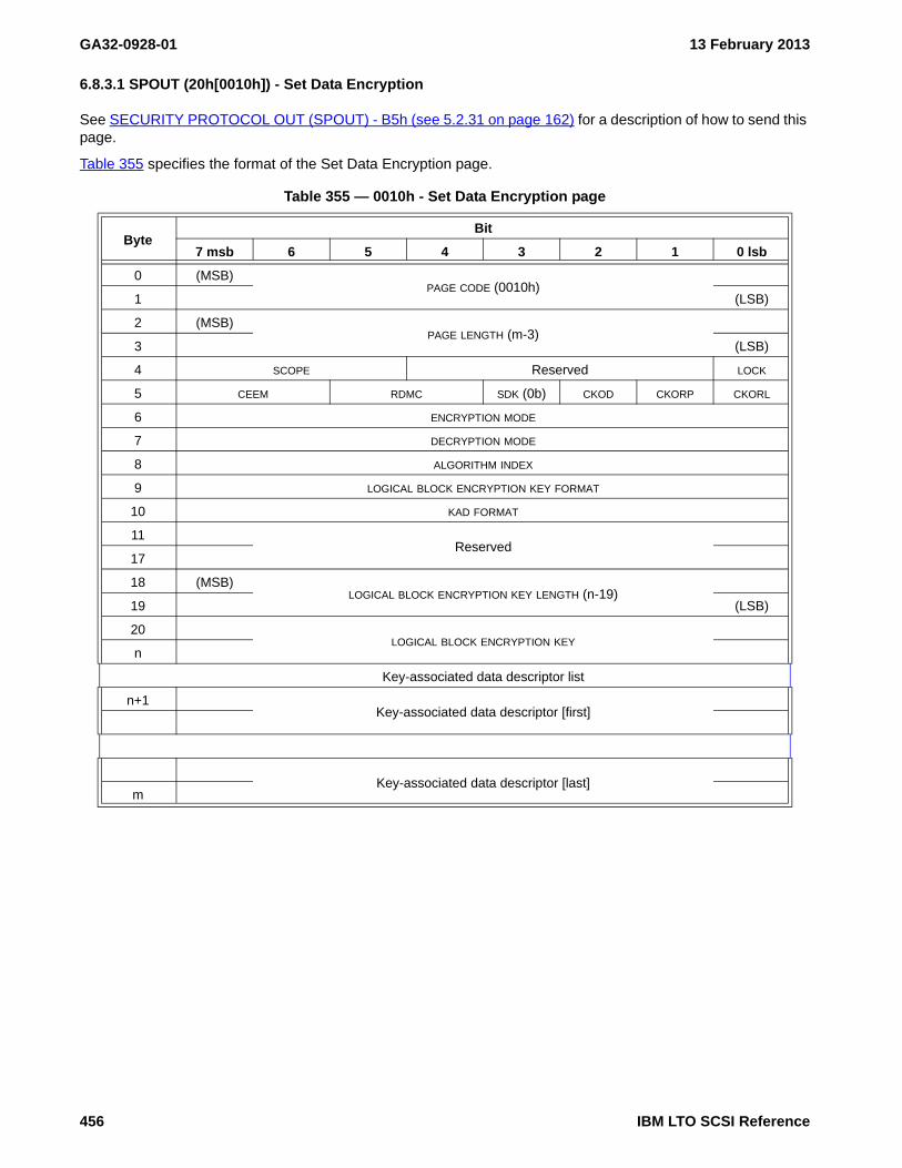
GA32-0928-01 13 February 2013
6.8.3.1 SPOUT (20h[0010h]) - Set Data Encryption
See SECURITY PROTOCOL OUT (SPOUT) - B5h (see 5.2.31 on page 162) for a description of how to send this page.
Table 355 specifies the format of the Set Data Encryption page.
Table 355 — 0010h - Set Data Encryption page
ByteBit
7 msb 6 5 4 3 2 1 0 lsb
0 (MSB)PAGE CODE (0010h)
1 (LSB)
2 (MSB)PAGE LENGTH (m-3)
3 (LSB)
4 SCOPE Reserved LOCK
5 CEEM RDMC SDK (0b) CKOD CKORP CKORL
6 ENCRYPTION MODE
7 DECRYPTION MODE
8 ALGORITHM INDEX
9 LOGICAL BLOCK ENCRYPTION KEY FORMAT
10 KAD FORMAT
11Reserved
17
18 (MSB)LOGICAL BLOCK ENCRYPTION KEY LENGTH (n-19)
19 (LSB)
20LOGICAL BLOCK ENCRYPTION KEY
n
Key-associated data descriptor list
n+1Key-associated data descriptor [first]
Key-associated data descriptor [last]m
456 IBM LTO SCSI Reference

13 February 2013 GA32-0928-01
The following parameters apply:
• SCOPE
Value Description0h Public1h Local2h All I_T Nexus
• LOCK
• CEEM (check external encryption mode)Value Description01b Do not check the encryption mode that was in use when the logical block was written to the
medium.10b On read and verify commands, check the encryption mode that was in use when the logical
block was written to the medium. Report an error if the logical block was written in EXTERNAL mode
11b On read and verify commands, check the encryption mode that was in use when the logical block was written to the medium. Report an error if the logical block was written in ENCRYPT mode
A CHECK CONDITION status, with the sense key set to ILLEGAL REQUEST, and the additional sense code set to INVALID FIELD IN PARAMETER DATA is returned if the CEEM field is set to either 10b or 11b, and:
a) the DECRYPTION MODE field is set to DISABLE; orb) the EAREM bit in the algorithm descriptor (see 6.8.2.3) for the algorithm specified by the ALGORITHM
INDEX field is set to zero.
• RDMC (raw decryption mode control)
This field is ignored if the ENCRYPTION MODE field is not set to ENCRYPT.
Value Description00b The device entity shall mark each encrypted logical block per the default setting for the
algorithm.10b The device entity shall mark each encrypted logical block written to the medium as enabled
for raw decryption mode operations.11b The device entity shall mark each encrypted logical block written to the medium as disabled
for raw decryption mode operations.
IBM LTO SCSI Reference 457

GA32-0928-01 13 February 2013
A CHECK CONDITION status, with the sense key set to ILLEGAL REQUEST and the additional sense key set to INVALID FIELD IN PARAMETER DATA is returned if:
a) the ENCRYPTION MODE field is set to ENCRYPT;b) the RDMC field is set to 10b or 11b; andc) the RDMC_C field in the algorithm descriptor for the encryption algorithm selected by the value in the
ALGORITHM INDEX field is set to 1h, 6h, or 7h.
• CKOD (clear key on demount)
• CKORP (clear key on reservation preempt)
• CKORL (clear key on reservation loss)
• ENCRYPTION MODE
Value Description0h Disable1h External2h Encrypt
• DECRYPTION MODE
Value Description0h Disable1h Raw2h Decrypt3h Mixed
• LOGICAL BLOCK ENCRYPTION KEY FORMAT
• KAD FORMAT
A non-zero value is only allowed if the algorithm in the ALGORITHM INDEX field reports a KADF_C bit set to one.
Value Description0h Unspecified1h Binary logical block encryption key name2h ASCII logical block encryption key name
If the KAD FORMAT value is non-zero, then:
a) a) only an A-KAD descriptor is provided and the authenticated key-associated data is the key name;b) b) only a U-KAD descriptor is provided and the unauthenticated key-associated data is the key
name; orc) c) both an A-KAD descriptor and a U-KAD descriptor is provided and the key name is formed by the
authenticated key-associated data followed by the unauthenticated key-associated data.
• LOGICAL BLOCK ENCRYPTION KEY LENGTH
Value Description0000h When no Key is specified0020h When Key is specified using Key Format 00h
• LOGICAL BLOCK ENCRYPTION KEY
• Key-Associated Descriptors List (See “Key-Associated Data (KAD) Descriptors” on page 460)
458 IBM LTO SCSI Reference

13 February 2013 GA32-0928-01
The following table indicates valid combinations of Encryption Mode and Decryption Mode and mandatory, optional and prohibited Key and Key-Associated Descriptors.
Table 356 — SPOUT (20h[0010h]) - KAD Parameters by Mode
EncryptionMode
DecryptionMode
R/WData
Key
Key-Associated Descriptors
NotesuKAD00h
aKAD(DKi)01h
Nonce02h
Metadata03h
0h Disable 0h Disable C/C P P P P P
0h Disable 1h Raw R/C P P P P P not recommended
0h Disable 2h Decrypt C4/C M 2 P P P P not recommended
0h Disable 3h Mixed C6/C M 2 P P P P
1h External 0h Disable C/R P P P P M 1 not recommended
1h External 1h Raw R/R P P P P M 1
1h External 2h Decrypt C4/R M 2 P P P M 1 not recommended
1h External 3h Mixed C6/R M 2 P P P M 1 not recommended
2h Encrypt 0h Disable C/C4 M 1 P O 1 O 1,3 P
2h Encrypt 1h Raw R/C4 M 1 P O 1 O 1,3 P not recommended
2h Encrypt 2h Decrypt C5/C4 M P O 1 O 1,3 P
2h Encrypt 3h Mixed C6/C4 M P O 1 O 1,3 P
Legend: M: element is mandatory (required) P: element prohibited (must not be present) O: element is optional (may be device generated) I: element is ignored (may be present) C: cleartext (not encrypted) R: raw (compressed encoded/encrypted)
Notes: 1: Only used for writing 2: Only used for reading 3: May be partially ignored 4: Data is encrypted 5: Data is decrypted 6: Data is decrypted (if needed)
IBM LTO SCSI Reference 459

GA32-0928-01 13 February 2013
6.8.3.2 Key-Associated Data (KAD) Descriptors
6.8.3.2.1 KAD 00h - UKAD (Unathenticated KAD)
The UKAD field is an optional field which is used when writing and is recorded with each record.
The following parameters apply:
• AUTHENTICATED
Value Description0h Reserved (must be set for Security Protocol Out - 0010h)1h Not Covered by Authentication (only Security Protocol In)
• KEY DESCRIPTOR LENGTH: Maximum size is determined by generation.
• UNATHENTICATED DATA
6.8.3.2.2 KAD 01h - DKi (Data Key Identifier)
The DKi KAD field is an optional field which is used when writing and is recorded with each record. This is the AKAD field.
The following parameters apply:
• AUTHENTICATED
Value Description0h Reserved (must be set for Security Protocol Out)2h No attempt has been made to authenticate (only Security Protocol In)
• KEY DESCRIPTOR LENGTH: may be up to 000Ch bytes
• DKi
Table 357 — KAD 00h - UKAD (Unathenticated KAD)
ByteBit
7 msb 6 5 4 3 2 1 0 lsb
0 KEY DESCRIPTOR TYPE (00h)
1 Reserved AUTHENTICATED
2 (MSB)KEY DESCRIPTOR LENGTH (n-3)
3 (LSB)
4UNAUTHENTICATED DATA
n
Table 358 — KAD 01h - DKi (Data Key Identifier)
ByteBit
7 msb 6 5 4 3 2 1 0 lsb
0 KEY DESCRIPTOR TYPE (01h)
1 Reserved AUTHENTICATED
2 (MSB)KEY DESCRIPTOR LENGTH (n-3)
3 (LSB)
4DKi
n
460 IBM LTO SCSI Reference

13 February 2013 GA32-0928-01
6.8.3.2.3 KAD 02h - Nonce
The Nonce/IV is not technically KAD. The Nonce may be set to provide the initial value for IV generation for write operations. This field is optional and the device is capable of generating high quality random IV values. When an application specifies nonce values, it is possible that a systemic cryptographic weakness may be introduced into the system. It is strongly recommended that nonce values are not supplied by the application.
NOTE 67 - The Nonce KAD is only reported by the device in Security Protocol In X'0020' - Data Encryption Status, and the value returned is the exact value specified in X'0010' - Set Data Encryption. This may not reflect the actual nonce or IV used for writing encrypted data.
NOTE 68 - IV values are constructed using only part of the specified Nonce value and are altered for each write in a device dependent manner.
The following parameters apply:
• AUTHENTICATED
Value Description0h Reserved (must be set for Security Protocol Out)1h Not Covered by Authentication (only Security Protocol In)
• KEY DESCRIPTOR LENGTH: the only supported length is 000Ch
• NONCE/IV
6.8.3.2.4 KAD 03h - MKAD (Metadata)
The MKAD field is used for a keyless copy operation (i.e., RAW decryption mode and EXTERNAL encryption mode).
Table 359 — KAD 02h - Nonce
ByteBit
7 msb 6 5 4 3 2 1 0 lsb
0 Key Descriptor Type (02h)
1 Reserved Authenticated
2 (MSB)KEY DESCRIPTOR LENGTH (000Ch)
3 (LSB)
4NONCE/IV
n
Table 360 — KAD 03h - MKAD (Metadata)
ByteBit
7 msb 6 5 4 3 2 1 0 lsb
0 KEY DESCRIPTOR TYPE (03h)
1 Reserved AUTHENTICATED (2h)
2 (MSB)KEY DESCRIPTOR LENGTH (n-3)
3 (LSB)
4KEY DESCRIPTOR
n
IBM LTO SCSI Reference 461

GA32-0928-01 13 February 2013
The following parameters apply:
• KEY DESCRIPTOR LENGTH
• KEY DESCRIPTOR: Data required by the encryption algorithm for a keyless copy operation.
462 IBM LTO SCSI Reference

13 February 2013 GA32-0928-01
This page intentionally left blank
IBM LTO SCSI Reference 463

GA32-0928-01 13 February 2013
464 IBM LTO SCSI Reference

13 February 2013 GA32-0928-01
Annex A. Summary of Drive Generation Differences
This chapter provides a summary of the differences in host attachment protocol between the Ultrium Internal Tape Drive (Generation 1), the TotalStorage® LTO Ultrium 2 Tape Drive (Generation 2), and the System Storage Ultrium 3 Tape Drive (Generation 3), the System Storage Ultrium 3 Half-High Tape Drive (Generation 3HH), the System Storage Ultrium 4 Tape Drive (Generation 4), the System Storage Ultrium 5 Tape Drive (Generation 5), and the System Storage Ultrium 6 Tape Drive (Generation 6).
The features of the Generation 2 drive that differ from the Generation 1 drive include:
a) 64-MiB read-and-write cacheb) Speed matchingc) Channel calibrationd) SET CAPACITY SCSI commande) Ultra160 SCSI interfacef) Drive external SCSI termination requiredg) Fibre Channel 2-Gb/s interfaceh) Fibre Channel support for direct connection to an F port (for example, a McData switch)i) Parallel SCSI Ultra 320 interface
The features of the Ultrium 3 Tape Drive that differ from those of the Ultrium 2 Tape Drive include the following:
a) 128 MiB read-and-write cacheb) New media, new media shell color (dark bluish gray, Pantone color number 7546C)c) Expanded request sense length to 96 bytesd) WORM capabilitye) Fibre Channel 2Gbit/sec interface or 4Gbit/sec interfacef) Half-Height drive option with:
A) Serial Attached SCSI (SAS) Interface, orB) Ultra160 SCSI Interface
The features of the Ultrium 4 Tape Drive that differ from those of the Ultrium 3 HH, Ultrium 3, and Ultrium 2 Tape Drive include the following:
a) Half-Height drive option with:A) Serial Attached SCSI (SAS) Interface, orB) Ultra160 SCSI Interface
b) 256 MiB read-and-write cachec) Encryption of data on Ultrium 4 cartridges
A) T10 key management methodB) Transparent management method
a) when using IBM® device driver, orb) when in an IBM library
d) New log pagesA) Device Statistics log page (14h)B) Tape Diagnostic data log page (16h)C) Performance Characteristics log page (37h)
e) Fibre Channel 4Gbit/sec interfacef) Serial Attached SCSI (SAS) interfaceg) Ultra320 SCSI Interface (OEM model only)h) WORM capability
The features of the Ultrium 5 Tape Drive that differ from those of the previous generations include the following:
a) Full-Height and Half-Height drive option with:A) Fibre Channel 8Gbit/sec Interface,orB) Serial Attached SCSI (SAS) 6Gbit/sec Interface
b) Full-Height 448 MiB read-and-write cachec) Half-Height 192 MiB read-and-write cache
A) Encryption of data on Ultrium 4 and Ultrium 5 cartridgesB) T10 key management method
IBM LTO SCSI Reference 465

GA32-0928-01 13 February 2013
C) Transparent management methoda) when using IBM device driver,b) when in an IBM library, orc) when using T10 External Encryption Control
d) Support for IKEv2-SCSIe) 14 Speeds in Digital Speed Matchingf) Partition capability up to two partitions (see 6.6.13)g) Data Safe Mode (i.e., Append-only mode) capability (see 4.1.3)h) SkipSync capability (see 6.6.21.5.1)i) Ideal Capacity (see 6.6.21.5.3)j) Dynamic Runtime Attributesk) Power Condition mode page for user controlled power management (see 6.6.16)l) Ethernet port for configuration/debug (see 6.6.21.3)m) Standards based setting of time (see 4.14)n) Logical block protection (i.e., CRC on bus; fixity checks; tape checksum) (see 4.5)o) Command timeout values reported at runtime with Report Supported Opcodes command (see 5.2.24)p) New standardized log pages with expanded counters:
A) Extended Device Statistics log page (14h) (see 6.4.10)B) Volume Statistics log page (17h) (see 6.4.12)C) Data Compression log page (1Bh) (see 6.4.14)
The features of the Ultrium 6 Tape Drive that differ from those of the previous generations include the following:
a) Full-Height and Half-Height drive option with:A) Fibre Channel 8Gbit/sec Interface,orB) Serial Attached SCSI (SAS) 6Gbit/sec Interface
b) Full-Height 860 MiB read-and-write cachec) Half-Height 348 MiB read-and-write cached) Encryption/Decryption of data
A) Encryption of data on Ultrium 5 and Ultrium 6 cartridgesB) Decryption of data on Ultrium 4, Ultrium 5, and Ultrium 6 cartridgesC) T10 key management methodD) Transparent key management method
a) if using IBM device driver,b) if in an IBM library, orc) if using T10 External Encryption Control
e) Support for IKEv2-SCSIf) 14 Speeds in Digital Speed Matchingg) Partition capability up to four partitions (see 6.6.13)h) Data Safe Mode (i.e., Append-only mode) capability (see 4.1.3)i) SkipSync capability (see 6.6.21.5.1)j) Ideal Capacity (see 6.6.21.5.3)k) Dynamic Runtime Attributesl) Power Condition mode page for user controlled power management (see 6.6.16)m) Ethernet port for configuration/debug/status (see 6.6.21.3)n) Standards based setting of time (see 4.14)o) Logical block protection (i.e., CRC on bus; fixity checks; tape checksum) (see 4.5)p) Command timeout values reported at runtime with Report Supported Opcodes command (see 5.2.24)q) Standards based retrieval of drive error logs (i.e., drive dump)r) New standardized log pages with expanded counters:
A) Extended Device Statistics log page (14h) (see 6.4.10)B) Volume Statistics log page (17h) (see 6.4.12)C) Data Compression log page (1Bh) (see 6.4.14)
466 IBM LTO SCSI Reference

13 February 2013 GA32-0928-01
Table 361 compares features of the different generations of Ultrium tape drives.
Table 361 — Features of the IBM Ultrium Tape Drives and the IBM 3580 Ultrium Tape Drive
Feature Ultrium 3Ultrium 3
Half-HeightUltrium 4
Ultrium 4Half-Height
Ultrium 5Ultrium 5
Half-HeightUltrium 6
Ultrium 6Half-Height
Native storage capacity
400 GB 400 GB 800 GB 800 GB 1500 GB 1500 GB 2500 GB 2500 GB
Storage capacity when compression enabled a
800 GB 800 GB 1.6 TB 1.6 TB 3.0 TB 3.0 TB 6250 GB 6250 GB
Native sustained data transfer rate
80 MB/s60 MB/s or80 MB/s f
120 MB/s 120 MB/s 140 MB/s 140 MB/s 160 MB/s 160 MB/s
Data transfer rate when compression enabled a
160 MB/s120 MB/s or160 MB/s f
240 MB/s 240 MB/s 280 MB/s 280 MB/s 400 MB/s 400 MB/s
Burst data transfer rate (1GFC)
100 MB/s N/A 100 MB/s 100 MB/s 100 MB/s 100 MB/s 100 MB/s 100 MB/s
Burst data transfer rate (2GFC)
200 MB/S N/A 200 MB/S 200 MB/S 200 MB/S 200 MB/S 200 MB/S 200 MB/S
Burst data transfer rate (4GFC)
400 MB/s N/A 400 MB/s 400 MB/s 400 MB/s 400 MB/s 400 MB/s 400 MB/s
Burst data transfer rate (8GFC)
N/A N/A N/A 800 MB/s f 800 MB/s 800 MB/s 800 MB/s 800 MB/s
Burst data transfer rate (3G SAS)
N/A 300 MB/s 300 MB/s 300 MB/s 300 MB/s 300 MB/s 300 MB/s 300 MB/s
Burst data transfer rate (6G SAS)
N/A 600 MB/s f N/A 600 MB/s f 600 MB/s 600 MB/s 600 MB/s 600 MB/s
Type of interfaceU160 e
LC-D bU160 e
SAS c
U160 e
LC-D b
SAS c
U320 d
LC-D b
SAS c
U320 d
LC-D b
SAS cLC-D b
SAS cLC-D b
SAS cLC-D b
SAS c
Note - All sustained data rates are dependent on the capabilities of the interconnect (for example, a 4GFC link is limited to less than 400MB/sec).
a The compression ratio in Generation 3 through Generation 5 is 2:1; Generation 6 is 2.5:1b LC-D: LC-Duplex Fibre Channel, with the use of SCSI protocolc SAS: Serial-Attached SCSId U320: Ultra 320 LVD SCSI - Not on V2 drivese U160: Ultra 160 LVD SCSI - Not on V2 drivesf V2 drives only
IBM LTO SCSI Reference 467

GA32-0928-01 13 February 2013
A.1. Differences in Command Timeout Values
Due to differences between each of the of the Ultrium drives, the maximum amount of time it takes for various SCSI commands to process and return status has changed. Table 362, “Command Timeout Values (Ultrium 1, 2, and 3 Full-Height) - OpCode Sort,” on page 469, Table 363, “Command Timeout Values (Ultrium 3 Half-Height and Ultrium 4) - OpCode Sort,” on page 471, Table 364, “Command Timeout Values (Ultrium 1, 2, and 3 Full-Height) - Alphabetic Sort,” on page 473, and Table 365, “Command Timeout Values (Ultrium 3 Half-Height and Ultrium 4) - Alphabetic Sort,” on page 475 each provides a list of all recommended host command time-outs from commands defined by the referenced SCSI-3 standard or by this product as vendor-unique for sequential access devices. The tables list the following information for each command: the operation code, recommended timeout, and notes.
It is strongly recommended that device drivers or host software implement device reservations using the Reserve or Persistent Reserve commands. Due to the sequential nature of tape devices, many host commands are serialized, and command time-outs consequently have an additive effect. Using reservations will prevent this from causing application disruptions in a multi-initiator or SAN environment. Similar additive timeout effects can occur if the host is using command Queuing (that is, simple queuing).
The time-outs in the following tables are based on the time from the start of the processing of the command, to its reported completion. Since applications are generally concerned with the time from the command being issued, to its reported completion, it should be noted that this overall time may be affected by currently processing operations. Some of these conditions include:
a) A prior command was issued with the Immediate bit set in the CDBb) Multiple concurrent commands with Simple queuing are processedc) Multi-initiator configurations without reservationsd) Non-host operations, such as manual unloads, power-on self tests, and so one) Commands issued shortly after certain aborted commandsf) Commands that force flushes when unwritten write data is in the buffer
Ultrium 5 and Ultrium 6 tape drives support the REPORT SUPPORTED OPERATION CODES - A3h[0Ch] (see 5.2.24 on page 139) command and provides command timeout values at run time. See the REPORT SUPPORTED OPERATION CODES command for Ultrium 5 and Ultrium 6 tape drive command timeouts. Command timeout values for Ultrium 1 through Ultrium 4 tape drives are listed in the following tables:
Table 362, “Command Timeout Values (Ultrium 1, 2, and 3 Full-Height) - OpCode Sort,” on page 469Table 363, “Command Timeout Values (Ultrium 3 Half-Height and Ultrium 4) - OpCode Sort,” on page 471Table 364, “Command Timeout Values (Ultrium 1, 2, and 3 Full-Height) - Alphabetic Sort,” on page 473Table 365, “Command Timeout Values (Ultrium 3 Half-Height and Ultrium 4) - Alphabetic Sort,” on page 475
468 IBM LTO SCSI Reference

13 February 2013 GA32-0928-01
Table 362 — Command Timeout Values (Ultrium 1, 2, and 3 Full-Height) - OpCode Sort (part 1 of 2)
OpCode Command
Timeoutfor
UltriumTapeDrive
(in minutes)
Timeout forUltrium 2
Tape Drive(in minutes)
Timeout forUltrium 3
Full-HeightTape Drive
(in minutes)
Gen 1Cartridge
Gen 2Cartridge
Gen 1Cartridge
Gen 2Cartridge
Gen 3Cartridge
00h TEST UNIT READY 1 1 1 1 1 1
01h REWIND 8 9 8 8 8 9
03h REQUEST SENSE 1 1 1 1 1 1
05h READ BLOCK LIMITS 1 1 1 1 1 1
08h READ 18 18 18 16 16 17
0Ah WRITE 18 18 18 N/A 16 18
0Bh SET CAPACITY N/A 13 13 N/A 11 12
10h WRITE FILEMARK 15 15 15 N/A 15 17
11hSPACE(6) (Normal) 16 15 14 14 14 16
SPACE(6) (Slow) 173 138 151 127 165 140
12h INQUIRY 1 1 1 1 1 1
13h VERIFY 18 18 18
15h/55h MODE SELECT(6/10) 1 1 1 1 1 1
16h/56h RESERVE UNIT(6/10) 1 1 1 1 1 1
17h/57h RELEASE UNIT(6/10) 1 1 1 1 1 1
19h ERASE 204 138 151 N/A 160 134
1Ah/5Ah MODE SENSE(6/10) 1 1 1 1 1 1
1Bh
LOAD (Cartridge Insert -> BOM) 11 12 12 8 8 8
LOAD (LP4 -> BOM) 8 9 8 8 8 9
UNLOAD (BOM -> Cartridge Eject) 10 10 10 10 10 11
UNLOAD (LP4 -> Cartridge Eject) 11 12 11 11 11 12
1Ch RECEIVE DIAGNOSTIC RESULTS 1 1 1 1 1 1
1Dh SEND DIAGNOSTIC 29 35 35 13 39 34
1Eh PREVENT/ALLOW MEDIUM REMOVAL 1 1 1 1 1 1
2Bh/92hLOCATE(10/16) (Normal) 16 15 14 14 14 16
LOCATE(10/16) (Slow) 173 138 151 127 165 140
34h READ POSITION 1 1 1 1 1 1
3Bh WRITE BUFFER 8 8 8 8 8 8
3Ch READ BUFFER 8 8 8 7 7 8
44h REPORT DENSITY SUPPORT 1 1 1 1 1 1
4Ch LOG SELECT 1 1 1 1 1 1
4Dh LOG SENSE 1 1 1 1 1 1
5Eh PERSISTENT RESERVE IN (PRIN) 1 1 1 1 1 1
5Fh PERSISTENT RESERVE OUT (PROUT) 1 1 1 1 1 1
IBM LTO SCSI Reference 469

GA32-0928-01 13 February 2013
8Ch READ ATTRIBUTE 1 1 1 1 1 1
8Dh WRITE ATTRIBUTE 1 1 1 1 1 1
91hSPACE(16) (Normal) N/A N/A N/A 14 14 16
SPACE(16) (Slow) N/A N/A N/A 127 165 140
A0h REPORT LUNS 1 1 1 1 1 1
A2h SECURITY PROTOCOL IN (SPIN) N/A N/A N/A N/A N/A 1
A3h:0ChREPORT SUPPORTED OPERATION CODES
N/A N/A N/A 1 1 1
A3h:0DhREPORT SUPPORTED TASK MANAGEMENT FUNCTIONS
N/A N/A N/A 1 1 1
A3h:0Fh REPORT TIMESTAMP N/A N/A N/A 1 1 1
A4h:0Fh SET TIMESTAMP N/A N/A N/A 1 1 1
B5h SECURITY PROTOCOL OUT (SPOUT) N/A N/A N/A N/A N/A N/A
Table 362 — Command Timeout Values (Ultrium 1, 2, and 3 Full-Height) - OpCode Sort (part 2 of 2)
OpCode Command
Timeoutfor
UltriumTapeDrive
(in minutes)
Timeout forUltrium 2
Tape Drive(in minutes)
Timeout forUltrium 3
Full-HeightTape Drive
(in minutes)
Gen 1Cartridge
Gen 2Cartridge
Gen 1Cartridge
Gen 2Cartridge
Gen 3Cartridge
470 IBM LTO SCSI Reference

13 February 2013 GA32-0928-01
Table 363 — Command Timeout Values (Ultrium 3 Half-Height and Ultrium 4) - OpCode Sort (part 1 of 2)
OpCode Command
Timeout for Ultrium 3 Half-Height Tape drive
(in minutes)
Timeout for Ultrium 4Tape Drive
(in minutes)
Gen 1Cartridge
Gen 2Cartridge
Gen 3Cartridge
Gen 2Cartridge
Gen 3Cartridge
Gen 4Cartridge
00h TEST UNIT READY 1 1 1 1 1 1
01h REWIND 11 11 13 8 9 9
03h REQUEST SENSE 1 1 1 1 1 1
05h READ BLOCK LIMITS 1 1 1 1 1 1
08h READ 21 21 23 16 17 22 c
0Ah WRITE N/A 21 24 N/A 18 23 d
0Bh SET CAPACITY N/A 14 16 N/A 12 12
10h WRITE FILEMARK N/A 21 23 N/A 17 22 e
11hSPACE(6) (Normal) 20 20 22 14 16 21
SPACE(6) (Slow) 199 264 201 165 140 183
12h INQUIRY 1 1 1 1 1 1
13h VERIFY 21 21 23 16 17 22 c
15h/55h MODE SELECT (6/10) 1 1 1 1 1 1
16h/56h RESERVE UNIT (6/10) 1 1 1 1 1 1
17h/57h RELEASE UNIT (6/10) 1 1 1 1 1 1
19h ERASE N/A 191 255 N/A 134 180 a
1Ah/5Ah MODE SENSE (6/10) 1 1 1 1 1 1
1Bh
LOAD (Cartridge Insert -> BOM) 9 9 9 8 8 8 b
LOAD (LP4 -> BOM) 11 11 13 8 9 9 b
UNLOAD (BOM -> Cartridge Eject) 12 12 14 10 11 11
UNLOAD (LP4 -> Cartridge Eject) 14 14 16 11 12 13
1Ch RECEIVE DIAGNOSTIC RESULTS 1 1 1 1 1 1
1Dh SEND DIAGNOSTIC 13 39 40 13 34 35
1Eh PREVENT/ALLOW MEDIUM REMOVAL 1 1 1 1 1 1
2Bh/92hLOCATE(10/16) (Normal) 20 20 22 14 16 21
LOCATE(10/16) (Slow) 199 264 201 165 140 183
34h READ POSITION 1 1 1 1 1 1
3Bh WRITE BUFFER 10 10 11 8 8 8
3Ch READ BUFFER 9 9 10 7 8 8
44h REPORT DENSITY SUPPORT 1 1 1 1 1 1
4Ch LOG SELECT 1 1 1 1 1 1
4Dh LOG SENSE 1 1 1 1 1 1
5Eh PERSISTENT RESERVE IN 1 1 1 1 1 1
5Fh PERSISTENT RESERVE OUT 1 1 1 1 1 1
91hSPACE(16) (NORMAL) 20 20 22 14 16 21
SPACE(16) (SLOW) 199 264 201 165 140 183
IBM LTO SCSI Reference 471

GA32-0928-01 13 February 2013
BCh READ ATTRIBUTE 1 1 1 1 1 1
BDh WRITE ATTRIBUTE 1 1 1 1 1 1
A0h REPORT LUNS 1 1 1 1 1 1
A2h SECURITY PROTOCOL IN N/A N/A N/A N/A N/A 1
A3h:0Ch REPORT SUPPORTED OP CODES 1 1 1 1 1 1
A3h:0DhREPORT SUPPORTED TASK MANAGEMENT FUNCTIONS
1 1 1 1 1 1
A3h:0Fh REPORT TIMESTAMP 1 1 1 1 1 1
A4h:0Fh SET TIMESTAMP 1 1 1 1 1 1
B5h SECURITY PROTOCOL OUT N/A N/A N/A N/A N/A 1a ERASE (at BOP): The following commands require an increased timeout when encryption is active and an
out-of-band key manager is used. The command timeout should be increased by 300 seconds. The following commands require an increased timeout when encryption is active and new wrapped or tracked keys are used. The command timeout should be increased by 600 seconds.
b LOAD (Unload): Special note: This command may require an increased timeout when encryption is active and the drive is set to request keys on mount, (the following commands require an increased timeout when encryption is active and an out-of-band key manager is used; the command timeout should be increased by 300 seconds), or when medium is loaded which has a drive detected key redundancy exposure (timeout increases by 900 seconds for recovery actions).
c READ/VERIFY: The following commands require an increased timeout when encryption is active and an out-of-band key manager is used. The command timeout should be increased by 300 seconds.
d WRITE: The following commands require an increased timeout when encryption is active and an out-of-band key manager is used. The command timeout should be increased by 300 seconds. The following commands require an increased timeout when encryption is active and new wrapped or tracked keys are used. The command timeout should be increased by 600 seconds, (at BOP with new key, longer if not at BOP with new key).
e WRITE FILEMARKS (at BOP): The following commands require an increased timeout when encryption is active and an out-of-band key manager is used. The command timeout should be increased by 300 seconds. The following commands require an increased timeout when encryption is active and new wrapped or tracked keys are used. The command timeout should be increased by 600 seconds.
Table 363 — Command Timeout Values (Ultrium 3 Half-Height and Ultrium 4) - OpCode Sort (part 2 of 2)
OpCode Command
Timeout for Ultrium 3 Half-Height Tape drive
(in minutes)
Timeout for Ultrium 4Tape Drive
(in minutes)
Gen 1Cartridge
Gen 2Cartridge
Gen 3Cartridge
Gen 2Cartridge
Gen 3Cartridge
Gen 4Cartridge
472 IBM LTO SCSI Reference

13 February 2013 GA32-0928-01
Table 364 — Command Timeout Values (Ultrium 1, 2, and 3 Full-Height) - Alphabetic Sort (part 1 of 2)
OpCode Command
Timeoutfor
UltriumTapeDrive
(in minutes)
Timeout forUltrium 2
Tape Drive(in minutes)
Timeout forUltrium 3
Full-HeightTape Drive
(in minutes)
Gen 1Cartridge
Gen 2Cartridge
Gen 1Cartridge
Gen 2Cartridge
Gen 3Cartridge
19h ERASE 204 138 151 N/A 160 134
12h INQUIRY 1 1 1 1 1 1
1BhLOAD (Cartridge Insert -> BOM) 11 12 12 8 8 8
LOAD (LP4 -> BOM) 8 9 8 8 8 9
2Bh/92hLOCATE(10/16) (Normal) 16 15 14 14 14 16
LOCATE(10/16) (Slow) 173 138 151 127 165 140
4Ch LOG SELECT 1 1 1 1 1 1
4Dh LOG SENSE 1 1 1 1 1 1
15h/55h MODE SELECT(6/10) 1 1 1 1 1 1
1Ah/5Ah MODE SENSE(6/10) 1 1 1 1 1 1
5Eh PERSISTENT RESERVE IN (PRIN) 1 1 1 1 1 1
5Fh PERSISTENT RESERVE OUT (PROUT) 1 1 1 1 1 1
1Eh PREVENT/ALLOW MEDIUM REMOVAL 1 1 1 1 1 1
08h READ 18 18 18 16 16 17
8Ch READ ATTRIBUTE 1 1 1 1 1 1
05h READ BLOCK LIMITS 1 1 1 1 1 1
3Ch READ BUFFER 8 8 8 7 7 8
34h READ POSITION 1 1 1 1 1 1
1Ch RECEIVE DIAGNOSTIC RESULTS 1 1 1 1 1 1
17h/57h RELEASE UNIT(6/10) 1 1 1 1 1 1
44h REPORT DENSITY SUPPORT 1 1 1 1 1 1
A0h REPORT LUNS 1 1 1 1 1 1
A3h:0ChREPORT SUPPORTED OPERATION CODES
N/A N/A N/A 1 1 1
A3h:0DhREPORT SUPPORTED TASK MANAGEMENT FUNCTIONS
N/A N/A N/A 1 1 1
A3h:0Fh REPORT TIMESTAMP N/A N/A N/A 1 1 1
03h REQUEST SENSE 1 1 1 1 1 1
16h/56h RESERVE UNIT(6/10) 1 1 1 1 1 1
01h REWIND 8 9 8 8 8 9
A2h SECURITY PROTOCOL IN (SPIN) N/A N/A N/A N/A N/A 1
B5h SECURITY PROTOCOL OUT (SPOUT) N/A N/A N/A N/A N/A N/A
1Dh SEND DIAGNOSTIC 29 35 35 13 39 34
0Bh SET CAPACITY N/A 13 13 N/A 11 12
A4h:0Fh SET TIMESTAMP N/A N/A N/A 1 1 1
IBM LTO SCSI Reference 473

GA32-0928-01 13 February 2013
91hSPACE(16) (Normal) N/A N/A N/A 14 14 16
SPACE(16) (Slow) N/A N/A N/A 127 165 140
11hSPACE(6) (Normal) 16 15 14 14 14 16
SPACE(6) (Slow) 173 138 151 127 165 140
00h TEST UNIT READY 1 1 1 1 1 1
1BhUNLOAD (BOM -> Cartridge Eject) 10 10 10 10 10 11
UNLOAD (LP4 -> Cartridge Eject) 11 12 11 11 11 12
13h VERIFY 18 18 18
0Ah WRITE 18 18 18 N/A 16 18
8Dh WRITE ATTRIBUTE 1 1 1 1 1 1
3Bh WRITE BUFFER 8 8 8 8 8 8
10h WRITE FILEMARK 15 15 15 N/A 15 17
Table 364 — Command Timeout Values (Ultrium 1, 2, and 3 Full-Height) - Alphabetic Sort (part 2 of 2)
OpCode Command
Timeoutfor
UltriumTapeDrive
(in minutes)
Timeout forUltrium 2
Tape Drive(in minutes)
Timeout forUltrium 3
Full-HeightTape Drive
(in minutes)
Gen 1Cartridge
Gen 2Cartridge
Gen 1Cartridge
Gen 2Cartridge
Gen 3Cartridge
474 IBM LTO SCSI Reference

13 February 2013 GA32-0928-01
Table 365 — Command Timeout Values (Ultrium 3 Half-Height and Ultrium 4) - Alphabetic Sort (part 1 of 2)
OpCode Command
Timeout for Ultrium 3 Half-Height Tape drive
(in minutes)
Timeout for Ultrium 4Tape Drive
(in minutes)
Gen 1Cartridge
Gen 2Cartridge
Gen 3Cartridge
Gen 2Cartridge
Gen 3Cartridge
Gen 4Cartridge
19h ERASE N/A 191 255 N/A 134 180 a
12h INQUIRY 1 1 1 1 1 1
1BhLOAD (Cartridge Insert -> BOM) 9 9 9 8 8 8 b
LOAD (LP4 -> BOM) 11 11 13 8 9 9 b
2Bh/92hLOCATE(10/16) (Normal) 20 20 22 14 16 21
LOCATE(10/16) (Slow) 199 264 201 165 140 183
4Ch LOG SELECT 1 1 1 1 1 1
4Dh LOG SENSE 1 1 1 1 1 1
15h/55h MODE SELECT (6/10) 1 1 1 1 1 1
1Ah/5Ah MODE SENSE (6/10) 1 1 1 1 1 1
5Eh PERSISTENT RESERVE IN 1 1 1 1 1 1
5Fh PERSISTENT RESERVE OUT 1 1 1 1 1 1
1Eh PREVENT/ALLOW MEDIUM REMOVAL 1 1 1 1 1 1
08h READ 21 21 23 16 17 22 c
BCh READ ATTRIBUTE 1 1 1 1 1 1
05h READ BLOCK LIMITS 1 1 1 1 1 1
3Ch READ BUFFER 9 9 10 7 8 8
34h READ POSITION 1 1 1 1 1 1
1Ch RECEIVE DIAGNOSTIC RESULTS 1 1 1 1 1 1
17h/57h RELEASE UNIT (6/10) 1 1 1 1 1 1
44h REPORT DENSITY SUPPORT 1 1 1 1 1 1
A0h REPORT LUNS 1 1 1 1 1 1
A3h:0Ch REPORT SUPPORTED OP CODES 1 1 1 1 1 1
A3h:0DhREPORT SUPPORTED TASK MANAGEMENT FUNCTIONS
1 1 1 1 1 1
A3h:0Fh REPORT TIMESTAMP 1 1 1 1 1 1
03h REQUEST SENSE 1 1 1 1 1 1
16h/56h RESERVE UNIT (6/10) 1 1 1 1 1 1
01h REWIND 11 11 13 8 9 9
A2h SECURITY PROTOCOL IN N/A N/A N/A N/A N/A 1
B5h SECURITY PROTOCOL OUT N/A N/A N/A N/A N/A 1
1Dh SEND DIAGNOSTIC 13 39 40 13 34 35
0Bh SET CAPACITY N/A 14 16 N/A 12 12
A4h:0Fh SET TIMESTAMP 1 1 1 1 1 1
11h/91hSPACE(16) (Normal) 20 20 22 14 16 21
SPACE(16) (Slow) 199 264 201 165 140 183
IBM LTO SCSI Reference 475
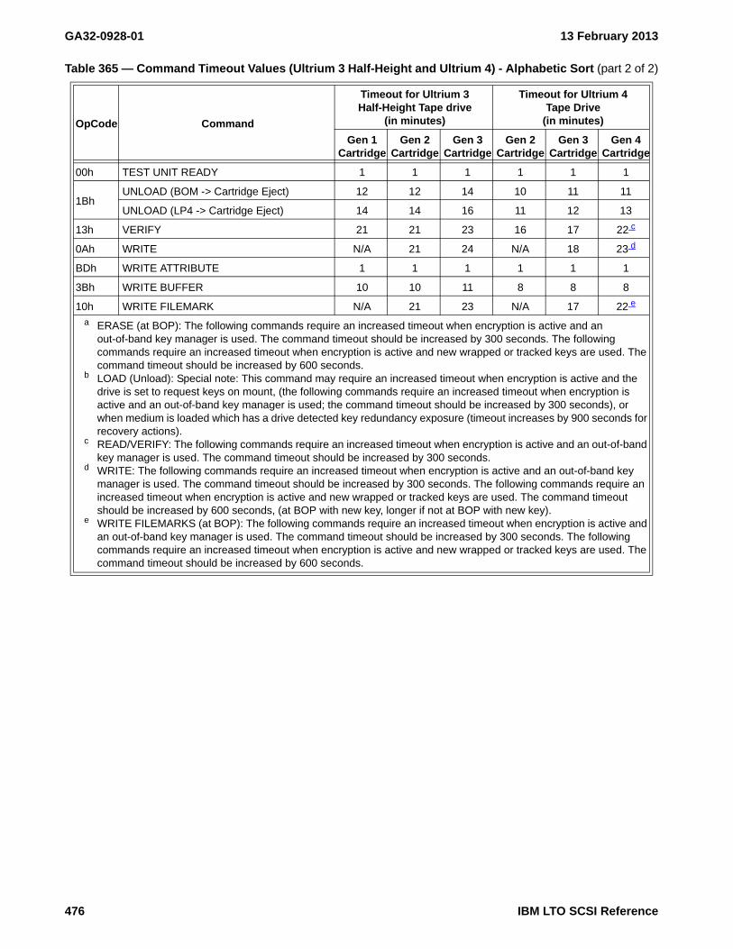
GA32-0928-01 13 February 2013
00h TEST UNIT READY 1 1 1 1 1 1
1BhUNLOAD (BOM -> Cartridge Eject) 12 12 14 10 11 11
UNLOAD (LP4 -> Cartridge Eject) 14 14 16 11 12 13
13h VERIFY 21 21 23 16 17 22 c
0Ah WRITE N/A 21 24 N/A 18 23 d
BDh WRITE ATTRIBUTE 1 1 1 1 1 1
3Bh WRITE BUFFER 10 10 11 8 8 8
10h WRITE FILEMARK N/A 21 23 N/A 17 22 e
a ERASE (at BOP): The following commands require an increased timeout when encryption is active and an out-of-band key manager is used. The command timeout should be increased by 300 seconds. The following commands require an increased timeout when encryption is active and new wrapped or tracked keys are used. The command timeout should be increased by 600 seconds.
b LOAD (Unload): Special note: This command may require an increased timeout when encryption is active and the drive is set to request keys on mount, (the following commands require an increased timeout when encryption is active and an out-of-band key manager is used; the command timeout should be increased by 300 seconds), or when medium is loaded which has a drive detected key redundancy exposure (timeout increases by 900 seconds for recovery actions).
c READ/VERIFY: The following commands require an increased timeout when encryption is active and an out-of-band key manager is used. The command timeout should be increased by 300 seconds.
d WRITE: The following commands require an increased timeout when encryption is active and an out-of-band key manager is used. The command timeout should be increased by 300 seconds. The following commands require an increased timeout when encryption is active and new wrapped or tracked keys are used. The command timeout should be increased by 600 seconds, (at BOP with new key, longer if not at BOP with new key).
e WRITE FILEMARKS (at BOP): The following commands require an increased timeout when encryption is active and an out-of-band key manager is used. The command timeout should be increased by 300 seconds. The following commands require an increased timeout when encryption is active and new wrapped or tracked keys are used. The command timeout should be increased by 600 seconds.
Table 365 — Command Timeout Values (Ultrium 3 Half-Height and Ultrium 4) - Alphabetic Sort (part 2 of 2)
OpCode Command
Timeout for Ultrium 3 Half-Height Tape drive
(in minutes)
Timeout for Ultrium 4Tape Drive
(in minutes)
Gen 1Cartridge
Gen 2Cartridge
Gen 3Cartridge
Gen 2Cartridge
Gen 3Cartridge
Gen 4Cartridge
476 IBM LTO SCSI Reference

13 February 2013 GA32-0928-01
A.2. Command and Parameter Differences Between Generations
Table A.1 shows commands and parameters added since Ultrium 1 and in which generation(s) it is applicable.
Table A.1 — Command and Parameter differences between generations
Command or Parameter DescriptionGeneration
2 3 4 5 6
ALLOW DATA OVERWRITECommand used in Append-only mode (also know as DataSafe mode) to allow an explicit overwrite
- - - Y Y
Volume Change Reference MAM Attribute
LTFS required MAM parameter - - - Y Y
Volume Coherency Information MAM Attribute
LTFS required MAM parameter - - - Y Y
FORMAT MEDIUM This command is related to partitioning - - - Y Y
REPORT SUPPORTED OPERATION CODES
- - Y Y Y
REPORT SUPPORTED TASK MANAGEMENT
- - Y Y Y
SET CAPACITYThe minimum capacity allowed varies by generation (see SET CAPACITY (not Ultrium 1)).
Y Y Y Y Y
Echo Buffer SupportEcho Buffer mode of the READ BUFFER and WRITE BUFFER commands (see READ BUFFER and WRITE BUFFER, respectively).
Y Y Y Y Y
Volume IdentifierVolume Identifier Part of the Device Attribute of Medium Auxiliary Memory (VolSer or BarCode value set by the library)
- - Y Y Y
SECURITY PROTOCOL IN (SPIN)This command is related to managing encryption. See SECURITY PROTOCOL IN (SPIN) A2h.
- - Y Y Y
SECURITY PROTOCOL OUT (SPOUT)
This command is related to managing encryption. See SECURITY PROTOCOL OUT (SPOUT) B5h.
- - Y Y Y
Key:- Not Supported
IBM LTO SCSI Reference 477

GA32-0928-01 13 February 2013
A.3. Data Changes Between Generations
The sections that follow describe the data changes between Generations of the Ultrium tape drive.
A.3.1. Standard Inquiry Data
The length of Standard Inquiry data on Ultrium 1 drives is less than on later generations. The Standard Inquiry data reported by Ultrium drives is shown in Table 11. The ADDITIONAL LENGTH field specifies how many bytes are returned. Currently, Ultrium 1 devices set this value to 33 (21h) and Ultrium 2 through Ultrium 4 devices set this value to 53 (35h). Ultrium 5 devices set this value to 65 (41h). This value is subject to change. It is strongly recommended that the user parse the data returned by using the ADDITIONAL LENGTH field instead of the published values.
Ultrium 5 drives add Protocol, Speed, and FIPS information as well as standardized version descriptors to Standard Inquiry.
Product Identification information returned is shown in Table 13.
For more information, see Standard Inquiry Data.
A.3.2. REPORT DENSITY SUPPORT Command
The REPORT DENSITY SUPPORT command has density values for all generations. Additionally, the units in which the Capacity value are returned changed in Ultrium 4 drives to match the SCSI standards and is carried forth in later generations to match the SCSI standards. See Table 272.
For more information, see REPORT DENSITY SUPPORT.
A.3.3. Mode Pages
On MODE SENSE commands the value returned in the MEDIUM TYPE field is shown in Table 157. On MODE SELECT commands any value is allowed and ignored.
Fibre Channel Port Control Page (19h) Page Length changed from 0Eh in Ultrium 1 drives to 06h in generation 2 drives. This matches the definition in the SCSI standards (FCP-2 and later). For more information, see Mode Page 19h: Protocol Specific Port Control Page.
A.3.4. READ POSITION Command
The READ POSITION command for all generation drives except Ultrium 1 behaves as described in the SCSI standards (SPC-2). Ultrium 5 added the Long data format and the extended data format parameter data. For more information, see READ POSITION.
A.3.5. Request Sense Changes
For Request Sense data, the Additional Sense Length is set to n-7, and is at least 10. When the sense data is associated with an Illegal Length read, the Additional Sense Length may be 10. In Ultrium 1 and Ultrium 2 drives, n can be as large as 35. In Ultrium 3 and later generation drives, n can be as large as 95. While this length is not anticipated to change, it is recommended that the Additional Sense Length be used to parse the data. For more information, see REQUEST SENSE.
478 IBM LTO SCSI Reference

13 February 2013 GA32-0928-01
A.4. Behavior Changes Between Generations
A.4.1. Cartridge Eject for Errors
Ultrium 1 drives auto-eject data cartridges when errors occur during loads. Later generation drives do not.
A.4.2. Queuing Issues
For all generations of drive later than Ultrium 1, when a cartridge is inserted into the drive through means other than SCSI commands to LUN 0, it is assumed that the host will poll the drive with TEST UNIT READY commands to determine its readiness before issuing in-order commands (for example, commands other than INQUIRY, TEST UNIT READY, REQUEST SENSE, or REPORT LUNS). If this is not the case, these commands may time out in ERP (Error Recovery Procedure) situations.
IBM LTO SCSI Reference 479

GA32-0928-01 13 February 2013
480 IBM LTO SCSI Reference

13 February 2013 GA32-0928-01
Annex B. Error Sense Information
This annex lists all possible combinations of Sense Keys, Additional Sense Codes (ASC), and Additional Sense Code Qualifiers (ASCQ) that are reported by this device.
NOTE 69 - ASCs of EEh and EFh are used for encryption related features and are only supported by encryption capable devices
NOTE 70 - When using encryption enabled devices in an in-band configuration (System method or key path), ASCs of EFh are used to initiate a key management session via a system proxy.
B.1. Sense Key 0 (No Sense)
Table 366 — ASC, and ASCQ Summary for Sense Key 0 (No Sense)
ASC ASCQ
Description
00 00 NO ADDITIONAL SENSE INFORMATION - (UNSOLICITED, NO CA/CC)
00 00 NO ADDITIONAL SENSE INFORMATION - EOM=1B (EARLY WARNING)
00 00 NO ADDITIONAL SENSE INFORMATION - ILI=1B
00 00 NO ADDITIONAL SENSE INFORMATION - FM=1B
00 01 FILEMARK DETECTED
00 02 END-OF-PARTITION/MEDIUM DETECTED, EARLY WARNING
00 04 BEGINNING-OF-PARTITION/MEDIUM DETECTED
00 07 PROGRAMMABLE EARLY WARNING DETECTED
00 16 OPERATION IN PROGRESS
5E 07 IDLE_C CONDITION ACTIVATED BY TIMER
82 82 DRIVE REQUIRES CLEARING
EF 13 ENCRYPTION - KEY TRANSLATE
Note - ASCs of EEh and EFh are used for encryption related features and are only supported by encryption capable devices
Note - When using encryption enabled devices in an in-band configuration (System method or key path), ASCs of EFh are used to initiate a key management session via a system proxy.
IBM LTO SCSI Reference 481
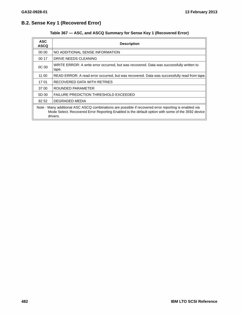
GA32-0928-01 13 February 2013
B.2. Sense Key 1 (Recovered Error)
Table 367 — ASC, and ASCQ Summary for Sense Key 1 (Recovered Error)
ASC ASCQ
Description
00 00 NO ADDITIONAL SENSE INFORMATION
00 17 DRIVE NEEDS CLEANING
0C 00WRITE ERROR: A write error occurred, but was recovered. Data was successfully written to tape.
11 00 READ ERROR: A read error occurred, but was recovered. Data was successfully read from tape.
17 01 RECOVERED DATA WITH RETRIES
37 00 ROUNDED PARAMETER
5D 00 FAILURE PREDICTION THRESHOLD EXCEEDED
82 52 DEGRADED MEDIA
Note - Many additional ASC ASCQ combinations are possible if recovered error reporting is enabled via Mode Select. Recovered Error Reporting Enabled is the default option with some of the 3592 device drivers.
482 IBM LTO SCSI Reference

13 February 2013 GA32-0928-01
B.3. Sense Key 2 (Not Ready)
Table 368 — ASC, and ASCQ Summary for Sense Key 2 (Not Ready)
ASC ASCQ
Description
04 00 LOGICAL UNIT NOT READY, CAUSE NOT REPORTABLE
04 01 LOGICAL UNIT IS IN PROCESS OF BECOMING READY
04 02 INITIALIZING COMMAND REQUIRED: A tape is present in the drive, but it is not logically loaded
04 12 LOGICAL UNIT NOT READY, OFFLINE
04 13 LOGICAL UNIT NOT READY, SA CREATION IN PROGRESS
0B 01 WARNING - SPECIFIED TEMPERATURE EXCEEDED
30 03 CLEANING IN PROGRESS
30 07 CLEANING FAILURE
3A 00 MEDIUM NOT PRESENT
3A 04 NOT READY - MEDIUM AUXILIARY MEMORY ACCESSIBLE
3E 00 LOGICAL UNIT HAS NOT SELF-CONFIGURED
53 00 MEDIA LOAD OR EJECT FAILED
74 11 SA CREATION PARAMETER VALUE REJECTED
IBM LTO SCSI Reference 483

GA32-0928-01 13 February 2013
B.4. Sense Key 3 (Medium Error)
Table 369 — ASC, and ASCQ Summary for Sense Key 3 (Medium Error)
ASC ASCQ
Description
04 10 LOGICAL UNIT NOT READY, AUXILIARY MEMORY NOT ACCESSIBLE
09 00 TRACK FOLLOWING ERROR
0C 00 WRITE ERROR
11 00 UNRECOVERED READ ERROR
11 12 AUXILIARY MEMORY READ ERROR
14 00 RECORDED ENTITY NOT FOUND
30 00 INCOMPATIBLE MEDIUM INSTALLED
30 01 CANNOT READ MEDIUM, UNKNOWN FORMAT
30 02 CANNOT READ MEDIUM, INCOMPATIBLE FORMAT
30 0D WORM MEDIUM - TAMPERING DETECTED
31 00 MEDIUM FORMAT CORRUPTED
3B 00 SEQUENTIAL POSITIONING ERROR
50 00 WRITE APPEND ERROR
51 00 ERASE FAILURE
52 00 CARTRIDGE FAULT
53 00 MEDIA LOAD OR EJECT FAILED
53 04 MEDIUM THREAD OR UNTHREAD FAILURE
EE 60 ENCRYPTION - PROXY COMMAND ERROR
EE D0 ENCRYPTION - DATA READ DECRYPTION FAILURE
EE D1 ENCRYPTION - DATA READ AFTER WRITE DECRYPTION FAILURE
EE E0 ENCRYPTION - KEY TRANSLATION FAILURE
EE E1 ENCRYPTION - KEY TRANSLATION AMBIGUOUS
EE F0 ENCRYPTION - DECRYPTION FENCED (READ)
EE F1 ENCRYPTION - ENCRYPTION FENCED (WRITE)
Note - ASCs of EEh and EFh are used for encryption related features and are only supported by encryption capable devices
Note - When using encryption enabled devices in an in-band configuration (System method or key path), ASCs of EFh are used to initiate a key management session via a system proxy.
484 IBM LTO SCSI Reference

13 February 2013 GA32-0928-01
B.5. Sense Key 4 (Hardware Error)
Table 370 — ASC, and ASCQ Summary for Sense Key 4 (Hardware Error)
ASC ASCQ
Description
04 03MANUAL INTERVENTION REQUIRED: A tape is present in the drive but could not be loaded or unloaded without manual intervention
10 01 LOGICAL BLOCK GUARD CHECK FAILED
40 XX DIAGNOSTIC FAILURE: The Additional Sense Code Qualifier (i.e., XX) indicates the failing component
41 00 DATA PATH FAILURE
44 00 INTERNAL TARGET FAILUREDrive Needs Cleaning, Warning Threshold Exceeded
51 00 ERASE FAILURE
52 00 CARTRIDGE FAULT
53 00 MEDIA LOAD OR EJECT FAILED
53 04 MEDIUM THREAD OR UNTHREAD FAILURE
EE 0E ENCRYPTION - KEY SERVICE TIME-OUT a
EE 0F ENCRYPTION - KEY SERVICE FAILURE a
Note - ASCs of EEh and EFh are used for encryption related features and are only supported by encryption capable devices
Note - When using encryption enabled devices in an in-band configuration (System method or key path), ASCs of EFh are used to initiate a key management session via a system proxy.
a Returned in LTO5 and earlier
IBM LTO SCSI Reference 485

GA32-0928-01 13 February 2013
B.6. Sense Key 5 (Illegal Request)
Table 371 — ASC, and ASCQ Summary for Sense Key 5 (Illegal Request) (part 1 of 2)
ASC ASCQ
Description
0E 03 INVALID FIELD IN COMMAND INFORMATION UNIT (e.g., FCP_DL error)
1A 00 PARAMETER LIST LENGTH ERROR
20 00 INVALID COMMAND OPERATION CODE
20 0C ILLEGAL COMMAND WHEN NOT IN APPEND-ONLY MODE
24 00 INVALID FIELD IN CDB
25 00 LOGICAL UNIT NOT SUPPORTED
26 00 INVALID FIELD IN PARAMETER LIST
26 02 PARAMETER VALUE INVALID
26 04 INVALID RELEASE OF PERSISTENT RESERVATION
26 11 ENCRYPTION - INCOMPLETE KEY-ASSOCIATE DATA SET
26 12 VENDOR SPECIFIC KEY REFERENCE NOT FOUND
29 04 DEVICE INTERNAL RESET
2A 0B ERROR HISTORY SNAPSHOT RELEASED
2C 00 COMMAND SEQUENCE ERROR
2C 0B NOT RESERVED - The OIR bit of the Sequential Access Device page is set and the I_T nexus attempting to communicate with the drive does not hold a reservation.
3B 00 SEQUENTIAL POSITIONING ERROR
3B 0CPOSITION PAST BEGINNING OF MEDIUM: A command that required the medium to be at BOP was attempted when the medium was not at BOP (for example, SET CAPACITY)
53 02 MEDIUM REMOVAL PREVENTED
55 08 MAXIMUM NUMBER OF SUPPLEMENTAL DECRYPTION KEYS EXCEEDED
74 08 DIGITAL SIGNATURE VALIDATION FAILURE
74 0C UNABLE TO DECRYPT PARAMETER LIST
74 10 SA CREATION PARAMETER VALUE INVALID
74 11 SA CREATION PARAMETER VALUE REJECTED
74 12 INVALID SA USAGE
74 30 SA CREATION PARAMETER NOT SUPPORTED
82 83BAD MICROCODE DETECTED: The data transferred to the drive during a firmware upgrade is corrupted or incompatible with the drive hardware
A3 01 OEM Vendor-specific
EE 00 ENCRYPTION - KEY SERVICE NOT ENABLED
EE 01 ENCRYPTION - KEY SERVICE NOT CONFIGURED
EE 02 ENCRYPTION - KEY SERVICE NOT AVAILABLE
EE 0D ENCRYPTION - MESSAGE CONTENT ERROR
EE 10 ENCRYPTION - KEY REQUIRED
EE 20 ENCRYPTION - KEY COUNT EXCEEDED
Note - ASCs of EEh and EFh are used for encryption related features and are only supported by encryption capable devices
Note - When using encryption enabled devices in an in-band configuration (System method or key path), ASCs of EFh are used to initiate a key management session via a system proxy.
486 IBM LTO SCSI Reference
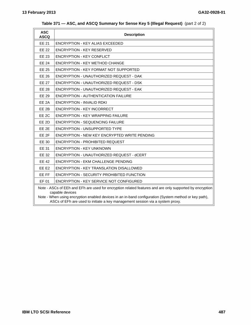
13 February 2013 GA32-0928-01
EE 21 ENCRYPTION - KEY ALIAS EXCEEDED
EE 22 ENCRYPTION - KEY RESERVED
EE 23 ENCRYPTION - KEY CONFLICT
EE 24 ENCRYPTION - KEY METHOD CHANGE
EE 25 ENCRYPTION - KEY FORMAT NOT SUPPORTED
EE 26 ENCRYPTION - UNAUTHORIZED REQUEST - DAK
EE 27 ENCRYPTION - UNAUTHORIZED REQUEST - DSK
EE 28 ENCRYPTION - UNAUTHORIZED REQUEST - EAK
EE 29 ENCRYPTION - AUTHENTICATION FAILURE
EE 2A ENCRYPTION - INVALID RDKI
EE 2B ENCRYPTION - KEY INCORRECT
EE 2C ENCRYPTION - KEY WRAPPING FAILURE
EE 2D ENCRYPTION - SEQUENCING FAILURE
EE 2E ENCRYPTION - UNSUPPORTED TYPE
EE 2F ENCRYPTION - NEW KEY ENCRYPTED WRITE PENDING
EE 30 ENCRYPTION - PROHIBITED REQUEST
EE 31 ENCRYPTION - KEY UNKNOWN
EE 32 ENCRYPTION - UNAUTHORIZED REQUEST - dCERT
EE 42 ENCRYPTION - EKM CHALLENGE PENDING
EE E2 ENCRYPTION - KEY TRANSLATION DISALLOWED
EE FF ENCRYPTION - SECURITY PROHIBITED FUNCTION
EF 01 ENCRYPTION - KEY SERVICE NOT CONFIGURED
Table 371 — ASC, and ASCQ Summary for Sense Key 5 (Illegal Request) (part 2 of 2)
ASC ASCQ
Description
Note - ASCs of EEh and EFh are used for encryption related features and are only supported by encryption capable devices
Note - When using encryption enabled devices in an in-band configuration (System method or key path), ASCs of EFh are used to initiate a key management session via a system proxy.
IBM LTO SCSI Reference 487

GA32-0928-01 13 February 2013
B.7. Sense Key 6 (Unit Attention)
Table 372 — ASC, and ASCQ Summary for Sense Key 6 (Unit Attention) (part 1 of 2)
ASC ASCQ
Description
28 00 NOT READY TO READY TRANSITION, MEDIUM MAY HAVE CHANGED
28 01 IMPORT OR EXPORT ELEMENT ACCESSED
29 00 POWER ON, RESET, OR BUS DEVICE RESET OCCURRED
29 04 DEVICE INTERNAL RESET
29 05 TRANSCEIVER MODE CHANGED TO SINGLE-ENDED
29 06 TRANSCEIVER MODE CHANGED TO LVD
2A 01 MODE PARAMETERS CHANGED
2A 02 LOG PARAMETERS CHANGED
2A 03 RESERVATIONS PREEMPTED
2A 04 RESERVATIONS RELEASED
2A 05 REGISTRATIONS PREEMPTED
2A 0A ERROR HISTORY I_T NEXUS CLEARED
2A 11 ENCRYPTION - DATA ENCRYPTION PARAMETERS CHANGED BY ANOTHER I_T NEXUS
2A 12ENCRYPTION - DATA ENCRYPTION PARAMETERS CHANGED BY VENDOR SPECIFIC EVENT
2A 14 SA CREATION CAPABILITIES DATA HAS CHANGED
2F 00 COMMANDS CLEARED BY ANOTHER INITIATOR
3B 12 MEDIUM MAGAZINE REMOVED
3B 13 MEDIUM MAGAZINE INSERTED
3F 01 MICROCODE HAS BEEN CHANGED
3F 02 CHANGED OPERATING DEFINITION
3F 03 INQUIRY DATA HAS CHANGED
3F 05 DEVICE IDENTIFIER CHANGED
3F 0E REPORTED LUNS DATA HAS CHANGED
5D FF FAILURE PREDICTION THRESHOLD EXCEEDED (FALSE)
EE 11 ENCRYPTION - KEY GENERATION
EE 12 ENCRYPTION - KEY CHANGE DETECTED
EE 13 ENCRYPTION - KEY TRANSLATION
EE 18 ENCRYPTION - CHANGED (READ)
EE 19 ENCRYPTION - CHANGED (WRITE)
EE 40 ENCRYPTION - EKM IDENTIFIER CHANGED
EE 41 ENCRYPTION - EKM CHALLENGE CHANGED
EE 50 ENCRYPTION - INITIATOR IDENTIFIER CHANGED
EE 51 ENCRYPTION - INITIATOR RESPONSE CHANGED
EF 01 ENCRYPTION - KEY SERVICE NOT CONFIGURED
Note - ASCs of EEh and EFh are used for encryption related features and are only supported by encryption capable devices
Note - When using encryption enabled devices in an in-band configuration (System method or key path), ASCs of EFh are used to initiate a key management session via a system proxy.
488 IBM LTO SCSI Reference

13 February 2013 GA32-0928-01
EF 10 ENCRYPTION - KEY REQUIRED
EF 11 ENCRYPTION - KEY GENERATION
EF 13 ENCRYPTION - KEY TRANSLATION
EF 1A ENCRYPTION - KEY OPTIONAL (i.e., chose encryption enabled/disabled)
Table 372 — ASC, and ASCQ Summary for Sense Key 6 (Unit Attention) (part 2 of 2)
ASC ASCQ
Description
Note - ASCs of EEh and EFh are used for encryption related features and are only supported by encryption capable devices
Note - When using encryption enabled devices in an in-band configuration (System method or key path), ASCs of EFh are used to initiate a key management session via a system proxy.
IBM LTO SCSI Reference 489

GA32-0928-01 13 February 2013
B.8. Sense Key 7 (Data Protect)
Table 373 — ASC, and ASCQ Summary for Sense Key 7 (Data Protect)
ASC ASCQ
Description
26 10 ENCRYPTION - DATA DECRYPTION KEY FAIL LIMIT
27 00 WRITE PROTECTED
2A 13 ENCRYPTION - DATA ENCRYPTION KEY INSTANCE COUNTER HAS CHANGED
30 05 CANNOT WRITE MEDIUM, INCOMPATIBLE FORMAT
30 06 CANNOT FORMAT MEDIUM - INCOMPATIBLE MEDIUM
30 0CDATA PROTECT/WORM MEDIUM - OVERWRITE ATTEMPTED: Set when the drive rejects a Write operation because the rules for allowing WORM writes have not been met
30 0DDATA PROTECT/WORM MEDIUM - INTEGRITY CHECK: Set when the drive rejects a Write operation because the current cartridge is a Suspicious WORM cartridge
50 01 WRITE APPEND POSITION ERROR (WORM)
52 00 CARTRIDGE FAULT
5A 02 OPERATOR SELECTED WRITE PROTECT
74 00 SECURITY ERROR
74 01 ENCRYPTION - UNABLE TO DECRYPT DATA
74 02 ENCRYPTION - UNENCRYPTED DATA ENCOUNTERED WHILE DECRYPTING
74 03 ENCRYPTION - INCORRECT DATA ENCRYPTION KEY
74 04 ENCRYPTION - CRYPTOGRAPHIC INTEGRITY VALIDATION FAILED
74 05 ENCRYPTION - ERROR DECRYPTING DATA
74 06 UNKNOWN SIGNATURE VERIFICATION KEY
74 07 ENCRYPTION PARAMETERS NOT USEABLE
74 09 ENCRYPTION MODE MISMATCH ON READ
74 0A ENCRYPTED BLOCK NOT RAW READ ENABLED
74 0B INCORRECT ENCRYPTION PARAMETERS
EE 0E ENCRYPTION - KEY SERVICE TIME-OUT a
EE 0F ENCRYPTION - KEY SERVICE FAILURE a
EF 10 ENCRYPTION - KEY REQUIRED
EF 11 ENCRYPTION - KEY GENERATION
EF 13 ENCRYPTION - KEY TRANSLATE
EF 1A ENCRYPTION - KEY OPTIONAL
EF A0 ENCRYPTION - KEY REQUIRED (T10)
EF A1 ENCRYPTION - KEY GENERATION (T10)
EF C0 ENCRYPTION - NO OPERATION
Note - ASCs of EEh and EFh are used for encryption related features and are only supported by encryption capable devices
Note - When using encryption enabled devices in an in-band configuration (System method or key path), ASCs of EFh are used to initiate a key management session via a system proxy.
a Returned in LTO6 and later
490 IBM LTO SCSI Reference

13 February 2013 GA32-0928-01
B.9. Sense Key 8 (Blank Check)
Table 374 — ASC, and ASCQ Summary for Sense Key 8 (Blank Check)
ASC ASCQ
Description
00 05 END-OF-DATA DETECTED
IBM LTO SCSI Reference 491
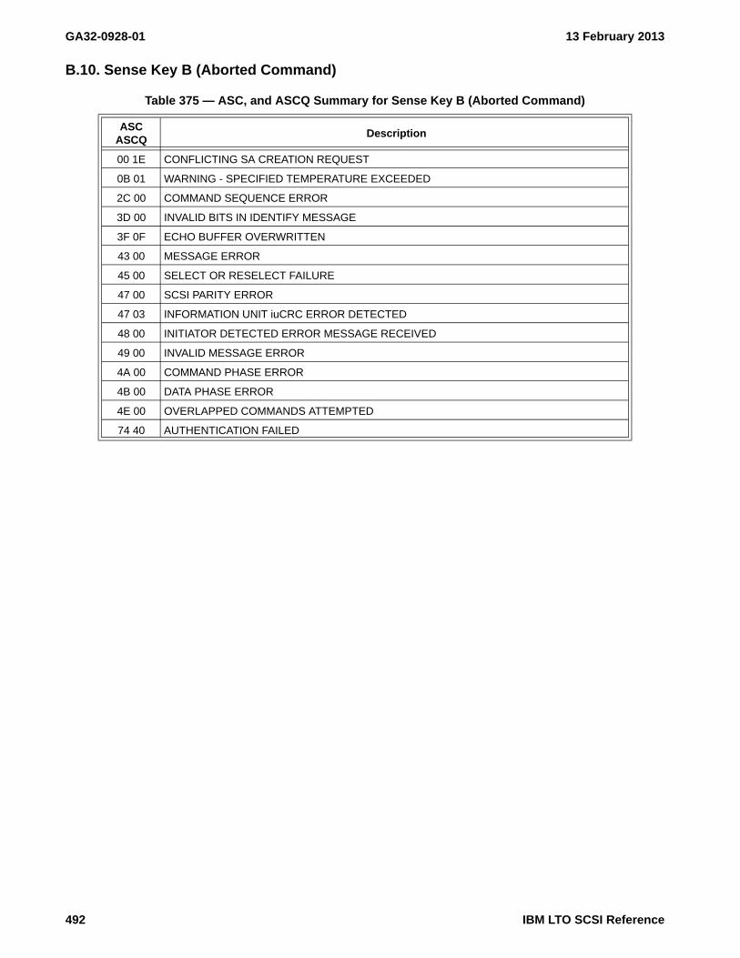
GA32-0928-01 13 February 2013
B.10. Sense Key B (Aborted Command)
Table 375 — ASC, and ASCQ Summary for Sense Key B (Aborted Command)
ASC ASCQ
Description
00 1E CONFLICTING SA CREATION REQUEST
0B 01 WARNING - SPECIFIED TEMPERATURE EXCEEDED
2C 00 COMMAND SEQUENCE ERROR
3D 00 INVALID BITS IN IDENTIFY MESSAGE
3F 0F ECHO BUFFER OVERWRITTEN
43 00 MESSAGE ERROR
45 00 SELECT OR RESELECT FAILURE
47 00 SCSI PARITY ERROR
47 03 INFORMATION UNIT iuCRC ERROR DETECTED
48 00 INITIATOR DETECTED ERROR MESSAGE RECEIVED
49 00 INVALID MESSAGE ERROR
4A 00 COMMAND PHASE ERROR
4B 00 DATA PHASE ERROR
4E 00 OVERLAPPED COMMANDS ATTEMPTED
74 40 AUTHENTICATION FAILED
492 IBM LTO SCSI Reference

13 February 2013 GA32-0928-01
B.11. Sense Key D (Volume Overflow)
Table 376 — ASC, and ASCQ Summary for Sense Key D (Volume Overflow)
ASC ASCQ
Description
00 02 END-OF-PARTITION/MEDIUM DETECTED
IBM LTO SCSI Reference 493

GA32-0928-01 13 February 2013
494 IBM LTO SCSI Reference

13 February 2013 GA32-0928-01
Annex C. Firmware Download
This annex describes how to compare a firmware level binary to information returned by a drive and determine which firmware is acceptable in which drive.
C.1. Identifying Level Hardware of Drive
The firmware that is loaded in the drive will report a LOAD ID and RU NAME in INQUIRY IP 03h: Firmware Designation (see 6.3.2 on page 243). The LOAD ID and RU NAME are used to designate the Level Hardware (i.e., Product). The following table defines the LOAD ID and RU NAME values for each Level Hardware.
Table 377 — Load ID and RU Name Designation for LTO2
Product(Level
Hardware)LOAD ID
RU NAME
“EBCDIC”Hex
Product ID(Left-Aligned)
IBM OEM eServer
U160 A1700299"AJEFGP99"
0xC1D1C5C6C7D7F9F9
ULT3580-TD2 ULTRIUM-TD2 -
FC2G A170029A"AJEFGP9A"
0xC1D1C5C6C7D7F9C1
U160 RoHS A1700D67"AJEFAX67"
0xC1D1C5C6C1E7F6F7
FC2G RoHS A1700D68"AJEFAX68"
0xC1D1C5C6C1E7F6F8
- Not ApplicableHH - Half-HighU - Ultra
IBM LTO SCSI Reference 495

GA32-0928-01 13 February 2013
Table 378 — Load ID and RU Name Designation for LTO3
Product(Level
Hardware)LOAD ID
RU Name“EBCDIC”
Hex
Product ID(Left-Aligned)
IBM OEM eServer
U160A1700D50
"AJEFAX50"0xC1D1C5C6C1E7F5F0
ULT3580-TD3 ULTRIUM-TD3 -U160 RoHS a
FC2GA1700D52
"AJEFAX52"0xC1D1C5C6C1E7F5F2FC4G RoHS a
HH SAS A1700D53"AJEFAX53"
0xC1D1C5C6C1E7F5F3- - HH LTO Gen 3
HH U160 A1700D69"AJEFAX69"
0xC1D1C5C6C1E7F6F9
HH SAS A1700D64"AJEFAX64"
0xC1D1C5C6C1E7F6F4
ULT3580-HH3 ULTRIUM-HH3
-
HH U160 A1700D63"AJEFAX63"
0xC1D1C5C6C1E7F6F3
HH SAS V2 A1700D79"AJEFAX79"
0xC1D1C5C6C1E7F7F9HH LTO Gen 3
- Not ApplicableHH - Half-HighU - Ultra
a Minimum level of firmware is 5BG2
496 IBM LTO SCSI Reference
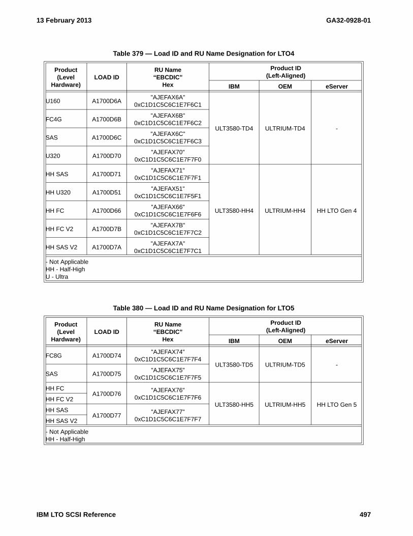
13 February 2013 GA32-0928-01
Table 379 — Load ID and RU Name Designation for LTO4
Product(Level
Hardware)LOAD ID
RU Name“EBCDIC”
Hex
Product ID(Left-Aligned)
IBM OEM eServer
U160 A1700D6A"AJEFAX6A"
0xC1D1C5C6C1E7F6C1
ULT3580-TD4 ULTRIUM-TD4 -
FC4G A1700D6B"AJEFAX6B"
0xC1D1C5C6C1E7F6C2
SAS A1700D6C"AJEFAX6C"
0xC1D1C5C6C1E7F6C3
U320 A1700D70"AJEFAX70"
0xC1D1C5C6C1E7F7F0
HH SAS A1700D71"AJEFAX71"
0xC1D1C5C6C1E7F7F1
ULT3580-HH4 ULTRIUM-HH4 HH LTO Gen 4
HH U320 A1700D51"AJEFAX51"
0xC1D1C5C6C1E7F5F1
HH FC A1700D66"AJEFAX66"
0xC1D1C5C6C1E7F6F6
HH FC V2 A1700D7B"AJEFAX7B"
0xC1D1C5C6C1E7F7C2
HH SAS V2 A1700D7A"AJEFAX7A"
0xC1D1C5C6C1E7F7C1
- Not ApplicableHH - Half-HighU - Ultra
Table 380 — Load ID and RU Name Designation for LTO5
Product(Level
Hardware)LOAD ID
RU Name“EBCDIC”
Hex
Product ID(Left-Aligned)
IBM OEM eServer
FC8G A1700D74"AJEFAX74"
0xC1D1C5C6C1E7F7F4ULT3580-TD5 ULTRIUM-TD5 -
SAS A1700D75"AJEFAX75"
0xC1D1C5C6C1E7F7F5
HH FCA1700D76
"AJEFAX76"0xC1D1C5C6C1E7F7F6
ULT3580-HH5 ULTRIUM-HH5 HH LTO Gen 5HH FC V2
HH SASA1700D77
"AJEFAX77"0xC1D1C5C6C1E7F7F7HH SAS V2
- Not ApplicableHH - Half-High
IBM LTO SCSI Reference 497

GA32-0928-01 13 February 2013
Table 381 — Load ID and RU Name Designation for LTO6
Product(Level
Hardware)LOAD ID
RU Name“EBCDIC”
Hex
Product ID(Left-Aligned)
IBM OEM eServer
FC8G A1700D81"AJEFAX81"
0xC1D1C5C6C1E7F8F1ULT3580-TD5 ULTRIUM-TD5 -
SAS A1700D82"AJEFAX82"
0xC1D1C5C6C1E7F8F2
HH FC A1700D83"AJEFAX83"
0xC1D1C5C6C1E7F8F3ULT3580-HH5 ULTRIUM-HH5 HH LTO Gen 5
HH SAS A1700D84"AJEFAX84"
0xC1D1C5C6C1E7F8F4
- Not ApplicableHH - Half-High
498 IBM LTO SCSI Reference

13 February 2013 GA32-0928-01
C.2. Identifying the product for which the firmware image is intended
The Firmware Image is defined in Table 398.
The LOAD ID and RU NAME fields in the Firmware Image are used to define the product (i.e., Level Hardware) for which the Firmware Image is intended.
Table 382 — Firmware Image
ByteBit
7 msb 6 5 4 3 2 1 0 osb
0Not Specified
3
4 (MSB)FIRMWARE LENGTH + HEADER LENGTH (m)
7 (LSB)
8 (MSB) LOAD ID(See “IP 03h: Firmware Designation” on page 243.)11
12 (MSB) FIRMWARE REVISION LEVEL (See Standard Inquiry Data bytes 32 - 35)15 (LSB)
16Reserved
23
24 (MSB) RU NAME (See “IP 03h: Firmware Designation” on page 243.)31 (LSB)
32Not Specified
m
IBM LTO SCSI Reference 499

GA32-0928-01 13 February 2013
C.3. Download Process
Confirm the Level Hardware of the Firmware Image (see C.2.) to be loaded matches the Level Hardware of the drive (see C.1.).
Download the Firmware Image using the WRITE BUFFER - 3Bh (see 5.2.41 on page 178) command.
500 IBM LTO SCSI Reference

13 February 2013 GA32-0928-01
Annex D. Sample C program to generate Reed-Solomon CRC
The following is sample C code for generating the Reed-Solomon CRC defined in ECMA-319
/*----------------------------------------------------------------------------** INPUTS: crc - initial crc (0 for fresh) (i.e., seed)** cnt - the number of data bytes to compute CRC for** start - the starting address of the data bytes (e.g., data buffer)** OUTPUTS: UINT32 - crc in big endian (MSB is first byte)*/UINT32 GenerateRSCRC(UINT32 crc, UINT32 cnt, const void *start){ static const UINT32 crcTable[256]= { 0x00000000,0x38CF3801,0x70837002,0x484C4803,0xE01BE004,0xD8D4D805, 0x90989006,0xA857A807,0xDD36DD08,0xE5F9E509,0xADB5AD0A,0x957A950B, 0x3D2D3D0C,0x05E2050D,0x4DAE4D0E,0x7561750F,0xA76CA710,0x9FA39F11, 0xD7EFD712,0xEF20EF13,0x47774714,0x7FB87F15,0x37F43716,0x0F3B0F17, 0x7A5A7A18,0x42954219,0x0AD90A1A,0x3216321B,0x9A419A1C,0xA28EA21D, 0xEAC2EA1E,0xD20DD21F,0x53D85320,0x6B176B21,0x235B2322,0x1B941B23, 0xB3C3B324,0x8B0C8B25,0xC340C326,0xFB8FFB27,0x8EEE8E28,0xB621B629, 0xFE6DFE2A,0xC6A2C62B,0x6EF56E2C,0x563A562D,0x1E761E2E,0x26B9262F, 0xF4B4F430,0xCC7BCC31,0x84378432,0xBCF8BC33,0x14AF1434,0x2C602C35, 0x642C6436,0x5CE35C37,0x29822938,0x114D1139,0x5901593A,0x61CE613B, 0xC999C93C,0xF156F13D,0xB91AB93E,0x81D5813F,0xA6ADA640,0x9E629E41, 0xD62ED642,0xEEE1EE43,0x46B64644,0x7E797E45,0x36353646,0x0EFA0E47, 0x7B9B7B48,0x43544349,0x0B180B4A,0x33D7334B,0x9B809B4C,0xA34FA34D, 0xEB03EB4E,0xD3CCD34F,0x01C10150,0x390E3951,0x71427152,0x498D4953, 0xE1DAE154,0xD915D955,0x91599156,0xA996A957,0xDCF7DC58,0xE438E459, 0xAC74AC5A,0x94BB945B,0x3CEC3C5C,0x0423045D,0x4C6F4C5E,0x74A0745F, 0xF575F560,0xCDBACD61,0x85F68562,0xBD39BD63,0x156E1564,0x2DA12D65, 0x65ED6566,0x5D225D67,0x28432868,0x108C1069,0x58C0586A,0x600F606B, 0xC858C86C,0xF097F06D,0xB8DBB86E,0x8014806F,0x52195270,0x6AD66A71, 0x229A2272,0x1A551A73,0xB202B274,0x8ACD8A75,0xC281C276,0xFA4EFA77, 0x8F2F8F78,0xB7E0B779,0xFFACFF7A,0xC763C77B,0x6F346F7C,0x57FB577D, 0x1FB71F7E,0x2778277F,0x51475180,0x69886981,0x21C42182,0x190B1983, 0xB15CB184,0x89938985,0xC1DFC186,0xF910F987,0x8C718C88,0xB4BEB489, 0xFCF2FC8A,0xC43DC48B,0x6C6A6C8C,0x54A5548D,0x1CE91C8E,0x2426248F, 0xF62BF690,0xCEE4CE91,0x86A88692,0xBE67BE93,0x16301694,0x2EFF2E95, 0x66B36696,0x5E7C5E97,0x2B1D2B98,0x13D21399,0x5B9E5B9A,0x6351639B, 0xCB06CB9C,0xF3C9F39D,0xBB85BB9E,0x834A839F,0x029F02A0,0x3A503AA1, 0x721C72A2,0x4AD34AA3,0xE284E2A4,0xDA4BDAA5,0x920792A6,0xAAC8AAA7, 0xDFA9DFA8,0xE766E7A9,0xAF2AAFAA,0x97E597AB,0x3FB23FAC,0x077D07AD, 0x4F314FAE,0x77FE77AF,0xA5F3A5B0,0x9D3C9DB1,0xD570D5B2,0xEDBFEDB3, 0x45E845B4,0x7D277DB5,0x356B35B6,0x0DA40DB7,0x78C578B8,0x400A40B9, 0x084608BA,0x308930BB,0x98DE98BC,0xA011A0BD,0xE85DE8BE,0xD092D0BF, 0xF7EAF7C0,0xCF25CFC1,0x876987C2,0xBFA6BFC3,0x17F117C4,0x2F3E2FC5, 0x677267C6,0x5FBD5FC7,0x2ADC2AC8,0x121312C9,0x5A5F5ACA,0x629062CB, 0xCAC7CACC,0xF208F2CD,0xBA44BACE,0x828B82CF,0x508650D0,0x684968D1, 0x200520D2,0x18CA18D3,0xB09DB0D4,0x885288D5,0xC01EC0D6,0xF8D1F8D7, 0x8DB08DD8,0xB57FB5D9,0xFD33FDDA,0xC5FCC5DB,0x6DAB6DDC,0x556455DD, 0x1D281DDE,0x25E725DF,0xA432A4E0,0x9CFD9CE1,0xD4B1D4E2,0xEC7EECE3, 0x442944E4,0x7CE67CE5,0x34AA34E6,0x0C650CE7,0x790479E8,0x41CB41E9, 0x098709EA,0x314831EB,0x991F99EC,0xA1D0A1ED,0xE99CE9EE,0xD153D1EF, 0x035E03F0,0x3B913BF1,0x73DD73F2,0x4B124BF3,0xE345E3F4,0xDB8ADBF5, 0x93C693F6,0xAB09ABF7,0xDE68DEF8,0xE6A7E6F9,0xAEEBAEFA,0x962496FB, 0x3E733EFC,0x06BC06FD,0x4EF04EFE,0x763F76FF};
UINT32 i;
IBM LTO SCSI Reference 501

GA32-0928-01 13 February 2013
const UINT8* d = start;
for ( i=0; i<cnt; i++ ) { crc = (crc << 8) ^ crcTable[*d ^ (crc >> 24)]; d++; }return crc;}
502 IBM LTO SCSI Reference

13 February 2013 GA32-0928-01
This page intentionally left blank
IBM LTO SCSI Reference 503

GA32-0928-01 13 February 2013
504 IBM LTO SCSI Reference

13 February 2013 GA32-0928-01
Annex E. Notices
E.1. Trademarks
The following terms are trademarks of International Business Machines Corporation in the United States or other countries (or regions) or both:
The following are U. S. trademarks of Hewlett-Packard Company, International Business Machines Corporation, and Seagate Technology:
Intel® and Itanium are registered trademarks of Intel Corporation in the United States, or other countries (or regions), or both.
Linux is a register trademark of Linus Torvalds.
NetBackup is a trademark of Symantec
Microsoft®, Windows®, Windows NT®, and the Windows logo are registered trademarks of Microsoft Corporation in the United States, or other countries (or regions), or both.
Other company, product, and service names may be trademarks or service marks of others.
AIX® OS/400® i5/OS
AS/400® pSeries® RAA
eServer™ SP zSeries
IBM® RS/6000® NetBackup (NBU)
iSeries® TotalStorage®
Linear Tape-Open
LTO
Ultrium
IBM LTO SCSI Reference 505

GA32-0928-01 13 February 2013
506 IBM LTO SCSI Reference

13 February 2013 GA32-0928-01
Index Of Counters (log parameters not in counter format are not included)Page
"DEAD DRIVE" Flag {3Ch:000Dh} . . . . . . . . . . . . . . . . . . . . . . . . . . . . . . . . . . . . . . . . . . . . . . . . . . . . . . . . . . . . . . . . . . 344"DEAD MEDIA" Flag {3Ch:000Ch} . . . . . . . . . . . . . . . . . . . . . . . . . . . . . . . . . . . . . . . . . . . . . . . . . . . . . . . . . . . . . . . . . 344"WORN MEDIA" Flag {3Ch:000Bh} . . . . . . . . . . . . . . . . . . . . . . . . . . . . . . . . . . . . . . . . . . . . . . . . . . . . . . . . . . . . . . . . . 344Abort Count [by port] {37h:0Fp8h} . . . . . . . . . . . . . . . . . . . . . . . . . . . . . . . . . . . . . . . . . . . . . . . . . . . . . . . . . . . . . . . . . . 334Abort Time [by port] {37h:0Fp9h} . . . . . . . . . . . . . . . . . . . . . . . . . . . . . . . . . . . . . . . . . . . . . . . . . . . . . . . . . . . . . . . . . . . 334Accumulated transitions to active . . . . . . . . . . . . . . . . . . . . . . . . . . . . . . . . . . . . . . . . . . . . . . . . . . . . . . . . . . . . . . . . . . . . 315Accumulated transitions to idle_c . . . . . . . . . . . . . . . . . . . . . . . . . . . . . . . . . . . . . . . . . . . . . . . . . . . . . . . . . . . . . . . . . . . . 315Active Capacity Efficiency {37h:7?00h} . . . . . . . . . . . . . . . . . . . . . . . . . . . . . . . . . . . . . . . . . . . . . . . . . . . . . . . . . . . . . . . 337Active CQs Loss (on-the-fly) {37h:7?13h} . . . . . . . . . . . . . . . . . . . . . . . . . . . . . . . . . . . . . . . . . . . . . . . . . . . . . . . . . . . . . 337Active Distance CQs (on-the-fly) {37h:7?23h} . . . . . . . . . . . . . . . . . . . . . . . . . . . . . . . . . . . . . . . . . . . . . . . . . . . . . . . . . . 337Active Distance DSS {37h:7?22h} . . . . . . . . . . . . . . . . . . . . . . . . . . . . . . . . . . . . . . . . . . . . . . . . . . . . . . . . . . . . . . . . . . . 337Active Distance Skip {37h:7?21h} . . . . . . . . . . . . . . . . . . . . . . . . . . . . . . . . . . . . . . . . . . . . . . . . . . . . . . . . . . . . . . . . . . . 337Active Distance Total {37h:7?2Fh} . . . . . . . . . . . . . . . . . . . . . . . . . . . . . . . . . . . . . . . . . . . . . . . . . . . . . . . . . . . . . . . . . . . 337Active DSS Loss {37h:7?12h} . . . . . . . . . . . . . . . . . . . . . . . . . . . . . . . . . . . . . . . . . . . . . . . . . . . . . . . . . . . . . . . . . . . . . . . 337Active Initiator Count {37h:0E00h} . . . . . . . . . . . . . . . . . . . . . . . . . . . . . . . . . . . . . . . . . . . . . . . . . . . . . . . . . . . . . . . . . . 333Active Skip Loss {37h:7?11h} . . . . . . . . . . . . . . . . . . . . . . . . . . . . . . . . . . . . . . . . . . . . . . . . . . . . . . . . . . . . . . . . . . . . . . . 337Active Sync Loss {37h:7?10h} . . . . . . . . . . . . . . . . . . . . . . . . . . . . . . . . . . . . . . . . . . . . . . . . . . . . . . . . . . . . . . . . . . . . . . 337Activity duty cycle {14h:0013h} . . . . . . . . . . . . . . . . . . . . . . . . . . . . . . . . . . . . . . . . . . . . . . . . . . . . . . . . . . . . . . . . . . . . . 292Approximate native capacity between BOP and EW of the current partition {0Ch:0005h} . . . . . . . . . . . . . . . . . . . . . . . . 276Approximate native capacity from BOP to EOD {0Ch:0004h} . . . . . . . . . . . . . . . . . . . . . . . . . . . . . . . . . . . . . . . . . . . . . 276Approximate native capacity from BOP to the current position of the medium {0Ch:0007h} . . . . . . . . . . . . . . . . . . . . . . 276Approximate native capacity of partition(s) {17h:0202h} . . . . . . . . . . . . . . . . . . . . . . . . . . . . . . . . . . . . . . . . . . . . . . . . . . 305Approximate remaining native capacity to early warning of partition(s) {17h:0204h} . . . . . . . . . . . . . . . . . . . . . . . . . . . 305Approximate used native capacity of partition(s) {17h:0203h} . . . . . . . . . . . . . . . . . . . . . . . . . . . . . . . . . . . . . . . . . . . . . 305Average Command Latency {37h:0DF0h} . . . . . . . . . . . . . . . . . . . . . . . . . . . . . . . . . . . . . . . . . . . . . . . . . . . . . . . . . . . . . 333Average Comp Buffer Rate {37h:2?92h} . . . . . . . . . . . . . . . . . . . . . . . . . . . . . . . . . . . . . . . . . . . . . . . . . . . . . . . . . . . . . . 336Average Comp Sync Length {37h:2?9Ch} . . . . . . . . . . . . . . . . . . . . . . . . . . . . . . . . . . . . . . . . . . . . . . . . . . . . . . . . . . . . . 336Average Comp Transfer Length {37h:2?98h} . . . . . . . . . . . . . . . . . . . . . . . . . . . . . . . . . . . . . . . . . . . . . . . . . . . . . . . . . . . 336Average Comp Transfer Rate {37h:2?91h} . . . . . . . . . . . . . . . . . . . . . . . . . . . . . . . . . . . . . . . . . . . . . . . . . . . . . . . . . . . . . 336Average Dequeue Latency {37h:0DF1h} . . . . . . . . . . . . . . . . . . . . . . . . . . . . . . . . . . . . . . . . . . . . . . . . . . . . . . . . . . . . . . 333Average Host Buffer Rate {37h:2?82h} . . . . . . . . . . . . . . . . . . . . . . . . . . . . . . . . . . . . . . . . . . . . . . . . . . . . . . . . . . . . . . . 336Average Host Sync Length {37h:2?8Ch} . . . . . . . . . . . . . . . . . . . . . . . . . . . . . . . . . . . . . . . . . . . . . . . . . . . . . . . . . . . . . . 336Average Host Transfer Length {37h:2?88h} . . . . . . . . . . . . . . . . . . . . . . . . . . . . . . . . . . . . . . . . . . . . . . . . . . . . . . . . . . . . 336Average Host Transfer Rate {37h:2?81h} . . . . . . . . . . . . . . . . . . . . . . . . . . . . . . . . . . . . . . . . . . . . . . . . . . . . . . . . . . . . . . 336Average Tape Buffer Rate {37h:2?A1h} . . . . . . . . . . . . . . . . . . . . . . . . . . . . . . . . . . . . . . . . . . . . . . . . . . . . . . . . . . . . . . . 336Band Change Count {37h:2?11h} . . . . . . . . . . . . . . . . . . . . . . . . . . . . . . . . . . . . . . . . . . . . . . . . . . . . . . . . . . . . . . . . . . . . 335Beginning of medium passes {17h:0101h} . . . . . . . . . . . . . . . . . . . . . . . . . . . . . . . . . . . . . . . . . . . . . . . . . . . . . . . . . . . . . 304Bytes read from medium {1Bh:0005h} . . . . . . . . . . . . . . . . . . . . . . . . . . . . . . . . . . . . . . . . . . . . . . . . . . . . . . . . . . . . . . . . 313Bytes read from tape {32h:0005h} . . . . . . . . . . . . . . . . . . . . . . . . . . . . . . . . . . . . . . . . . . . . . . . . . . . . . . . . . . . . . . . . . . . . 321Bytes transferred from application client {1Bh:0007h} . . . . . . . . . . . . . . . . . . . . . . . . . . . . . . . . . . . . . . . . . . . . . . . . . . . 313Bytes transferred from server {32h:0007h} . . . . . . . . . . . . . . . . . . . . . . . . . . . . . . . . . . . . . . . . . . . . . . . . . . . . . . . . . . . . . 321Bytes transferred to application client {1Bh:0003j} . . . . . . . . . . . . . . . . . . . . . . . . . . . . . . . . . . . . . . . . . . . . . . . . . . . . . . 313Bytes transferred to server {32h:0003h} . . . . . . . . . . . . . . . . . . . . . . . . . . . . . . . . . . . . . . . . . . . . . . . . . . . . . . . . . . . . . . . 321Bytes written to medium {1Bh:0009h} . . . . . . . . . . . . . . . . . . . . . . . . . . . . . . . . . . . . . . . . . . . . . . . . . . . . . . . . . . . . . . . . 314Bytes written to tape {32h:0009h} . . . . . . . . . . . . . . . . . . . . . . . . . . . . . . . . . . . . . . . . . . . . . . . . . . . . . . . . . . . . . . . . . . . . 321Cartridge Serial Number {3Ch:0015h} . . . . . . . . . . . . . . . . . . . . . . . . . . . . . . . . . . . . . . . . . . . . . . . . . . . . . . . . . . . . . . . . 344Clean Lifetime Mounts {3Dh:0060h} . . . . . . . . . . . . . . . . . . . . . . . . . . . . . . . . . . . . . . . . . . . . . . . . . . . . . . . . . . . . . . . . . 345Clean Requested Flag {3Ch:0011h} . . . . . . . . . . . . . . . . . . . . . . . . . . . . . . . . . . . . . . . . . . . . . . . . . . . . . . . . . . . . . . . . . . 344Cleaning Requested {0Ch:0100h}: . . . . . . . . . . . . . . . . . . . . . . . . . . . . . . . . . . . . . . . . . . . . . . . . . . . . . . . . . . . . . . . . . . . 276Command Count {37h:0Cp0h} . . . . . . . . . . . . . . . . . . . . . . . . . . . . . . . . . . . . . . . . . . . . . . . . . . . . . . . . . . . . . . . . . . . . . . 332Command Queue Count {37h:0CpCh} . . . . . . . . . . . . . . . . . . . . . . . . . . . . . . . . . . . . . . . . . . . . . . . . . . . . . . . . . . . . . . . . 332Command Queue Latency {37h:0CpDh} . . . . . . . . . . . . . . . . . . . . . . . . . . . . . . . . . . . . . . . . . . . . . . . . . . . . . . . . . . . . . . 333Command Queue Relative Time {37h:0CpEh} . . . . . . . . . . . . . . . . . . . . . . . . . . . . . . . . . . . . . . . . . . . . . . . . . . . . . . . . . . 333Command Relative Time {37h:0Cp2h} . . . . . . . . . . . . . . . . . . . . . . . . . . . . . . . . . . . . . . . . . . . . . . . . . . . . . . . . . . . . . . . . 332Command Timing {37h:0Cp1h} . . . . . . . . . . . . . . . . . . . . . . . . . . . . . . . . . . . . . . . . . . . . . . . . . . . . . . . . . . . . . . . . . . . . . 332
IBM LTO SCSI Reference 507

GA32-0928-01 13 February 2013
Command Transfer Byte Count from Host (out) {37h:0Cp9h} . . . . . . . . . . . . . . . . . . . . . . . . . . . . . . . . . . . . . . . . . . . . . . 332Command Transfer Byte Count to Host (in) {37h:0Cp5h} . . . . . . . . . . . . . . . . . . . . . . . . . . . . . . . . . . . . . . . . . . . . . . . . . 332Command Transfer Count from Host (out) {37h:0Cp8h} . . . . . . . . . . . . . . . . . . . . . . . . . . . . . . . . . . . . . . . . . . . . . . . . . . 332Command Transfer Count to Host (in) {37h:0Cp4h} . . . . . . . . . . . . . . . . . . . . . . . . . . . . . . . . . . . . . . . . . . . . . . . . . . . . . 332Command Transfer Timing from Host (out) {37h:0CpAh} . . . . . . . . . . . . . . . . . . . . . . . . . . . . . . . . . . . . . . . . . . . . . . . . 332Command Transfer Timing to Host (in) {37h:0Cp6h} . . . . . . . . . . . . . . . . . . . . . . . . . . . . . . . . . . . . . . . . . . . . . . . . . . . . 332Comp Buffer Efficiency {37h:2?94h} . . . . . . . . . . . . . . . . . . . . . . . . . . . . . . . . . . . . . . . . . . . . . . . . . . . . . . . . . . . . . . . . . 336Compressed Data (Medium) {37h:2?71h} . . . . . . . . . . . . . . . . . . . . . . . . . . . . . . . . . . . . . . . . . . . . . . . . . . . . . . . . . . . . . . 335Compressed Data {37h:2?61h} . . . . . . . . . . . . . . . . . . . . . . . . . . . . . . . . . . . . . . . . . . . . . . . . . . . . . . . . . . . . . . . . . . . . . . 335Compression Ratio {37h:2?6Ch} . . . . . . . . . . . . . . . . . . . . . . . . . . . . . . . . . . . . . . . . . . . . . . . . . . . . . . . . . . . . . . . . . . . . . 335Count {37h:0q00h} . . . . . . . . . . . . . . . . . . . . . . . . . . . . . . . . . . . . . . . . . . . . . . . . . . . . . . . . . . . . . . . . . . . . . . . . . . . . . . . 330Cumulative Cartridge Loads Counter {3Ch:0006h} . . . . . . . . . . . . . . . . . . . . . . . . . . . . . . . . . . . . . . . . . . . . . . . . . . . . . . 343Cumulative Cleaning Counter {3Ch:000Ah} . . . . . . . . . . . . . . . . . . . . . . . . . . . . . . . . . . . . . . . . . . . . . . . . . . . . . . . . . . . 344Cumulative Power On Time Counter {3Ch:0008h} . . . . . . . . . . . . . . . . . . . . . . . . . . . . . . . . . . . . . . . . . . . . . . . . . . . . . . 344Cumulative Time Tape is Loaded and Tensioned {3Ch:0009h} . . . . . . . . . . . . . . . . . . . . . . . . . . . . . . . . . . . . . . . . . . . . . 344Current Initiator {37h:0E03h} . . . . . . . . . . . . . . . . . . . . . . . . . . . . . . . . . . . . . . . . . . . . . . . . . . . . . . . . . . . . . . . . . . . . . . . 333Data Acquisition Temps {33h:0005h} . . . . . . . . . . . . . . . . . . . . . . . . . . . . . . . . . . . . . . . . . . . . . . . . . . . . . . . . . . . . . . . . . 322Data Acquisition Temps {34h:0005h} . . . . . . . . . . . . . . . . . . . . . . . . . . . . . . . . . . . . . . . . . . . . . . . . . . . . . . . . . . . . . . . . . 324Data compression enabled {1Bh:0100h} . . . . . . . . . . . . . . . . . . . . . . . . . . . . . . . . . . . . . . . . . . . . . . . . . . . . . . . . . . . . . . . 314Data Temps {33h:0007h} . . . . . . . . . . . . . . . . . . . . . . . . . . . . . . . . . . . . . . . . . . . . . . . . . . . . . . . . . . . . . . . . . . . . . . . . . . 322Data Temps {34h:0007h} . . . . . . . . . . . . . . . . . . . . . . . . . . . . . . . . . . . . . . . . . . . . . . . . . . . . . . . . . . . . . . . . . . . . . . . . . . 324Data Transients {33h:0002h} . . . . . . . . . . . . . . . . . . . . . . . . . . . . . . . . . . . . . . . . . . . . . . . . . . . . . . . . . . . . . . . . . . . . . . . . 322Data Transients {34h:0002h} . . . . . . . . . . . . . . . . . . . . . . . . . . . . . . . . . . . . . . . . . . . . . . . . . . . . . . . . . . . . . . . . . . . . . . . . 324Datarate Performance Impacting ERPs {37h:2?50h} . . . . . . . . . . . . . . . . . . . . . . . . . . . . . . . . . . . . . . . . . . . . . . . . . . . . . 335Dataset Overrun {34h:0019h} . . . . . . . . . . . . . . . . . . . . . . . . . . . . . . . . . . . . . . . . . . . . . . . . . . . . . . . . . . . . . . . . . . . . . . . 325Dataset Underrun {33h:000Fh} . . . . . . . . . . . . . . . . . . . . . . . . . . . . . . . . . . . . . . . . . . . . . . . . . . . . . . . . . . . . . . . . . . . . . . 323Datasets Corrected {33h:0000h} . . . . . . . . . . . . . . . . . . . . . . . . . . . . . . . . . . . . . . . . . . . . . . . . . . . . . . . . . . . . . . . . . . . . . 322Datasets Corrected {34h:0000h} . . . . . . . . . . . . . . . . . . . . . . . . . . . . . . . . . . . . . . . . . . . . . . . . . . . . . . . . . . . . . . . . . . . . . 324Datasets Processed {37h:2?68h} . . . . . . . . . . . . . . . . . . . . . . . . . . . . . . . . . . . . . . . . . . . . . . . . . . . . . . . . . . . . . . . . . . . . . 335Degate Data {37h:2?63h} . . . . . . . . . . . . . . . . . . . . . . . . . . . . . . . . . . . . . . . . . . . . . . . . . . . . . . . . . . . . . . . . . . . . . . . . . . 335Device Read Datasets Processed {38h:0006h} . . . . . . . . . . . . . . . . . . . . . . . . . . . . . . . . . . . . . . . . . . . . . . . . . . . . . . . . . . 338Device Read Datasets Transferred {38h:000Ah} . . . . . . . . . . . . . . . . . . . . . . . . . . . . . . . . . . . . . . . . . . . . . . . . . . . . . . . . 338Device Read Kebibytes Processed {38h:0007h} . . . . . . . . . . . . . . . . . . . . . . . . . . . . . . . . . . . . . . . . . . . . . . . . . . . . . . . . . 338Device Read Kebibytes Transferred {38h:000Bh} . . . . . . . . . . . . . . . . . . . . . . . . . . . . . . . . . . . . . . . . . . . . . . . . . . . . . . . 338Device Write Datasets Processed {38h:0004h} . . . . . . . . . . . . . . . . . . . . . . . . . . . . . . . . . . . . . . . . . . . . . . . . . . . . . . . . . . 338Device Write Datasets Transferred {38h:0008h} . . . . . . . . . . . . . . . . . . . . . . . . . . . . . . . . . . . . . . . . . . . . . . . . . . . . . . . . 338Device Write Kebibytes Processed {38h:0005h} . . . . . . . . . . . . . . . . . . . . . . . . . . . . . . . . . . . . . . . . . . . . . . . . . . . . . . . . 338Device Write Kebibytes Transferred {38h:0009h} . . . . . . . . . . . . . . . . . . . . . . . . . . . . . . . . . . . . . . . . . . . . . . . . . . . . . . . 338Drive Efficiency {37h:0000h} . . . . . . . . . . . . . . . . . . . . . . . . . . . . . . . . . . . . . . . . . . . . . . . . . . . . . . . . . . . . . . . . . . . . . . . 329Drive Lifetime Load Perms {3Dh:0092h} . . . . . . . . . . . . . . . . . . . . . . . . . . . . . . . . . . . . . . . . . . . . . . . . . . . . . . . . . . . . . . 346Drive Lifetime Load Temps {3Dh:00A2h} . . . . . . . . . . . . . . . . . . . . . . . . . . . . . . . . . . . . . . . . . . . . . . . . . . . . . . . . . . . . . 346Drive Lifetime Megabytes Read {3Dh:0042h} . . . . . . . . . . . . . . . . . . . . . . . . . . . . . . . . . . . . . . . . . . . . . . . . . . . . . . . . . . 345Drive Lifetime Megabytes Written {3Dh:0041h} . . . . . . . . . . . . . . . . . . . . . . . . . . . . . . . . . . . . . . . . . . . . . . . . . . . . . . . . 345Drive Lifetime Mounts {3Dh:0040h} . . . . . . . . . . . . . . . . . . . . . . . . . . . . . . . . . . . . . . . . . . . . . . . . . . . . . . . . . . . . . . . . . 345Drive Lifetime Read Perms {3Dh:0091h} . . . . . . . . . . . . . . . . . . . . . . . . . . . . . . . . . . . . . . . . . . . . . . . . . . . . . . . . . . . . . . 346Drive Lifetime Read Temps {3Dh:00A1h} . . . . . . . . . . . . . . . . . . . . . . . . . . . . . . . . . . . . . . . . . . . . . . . . . . . . . . . . . . . . . 346Drive Lifetime Unload Perms {3Dh:0093h} . . . . . . . . . . . . . . . . . . . . . . . . . . . . . . . . . . . . . . . . . . . . . . . . . . . . . . . . . . . . 346Drive Lifetime Unload Temps {3Dh:00A3h} . . . . . . . . . . . . . . . . . . . . . . . . . . . . . . . . . . . . . . . . . . . . . . . . . . . . . . . . . . . 346Drive Lifetime Write Perms {3Dh:0090h} . . . . . . . . . . . . . . . . . . . . . . . . . . . . . . . . . . . . . . . . . . . . . . . . . . . . . . . . . . . . . 346Drive Lifetime Write Temps {3Dh:00A0h} . . . . . . . . . . . . . . . . . . . . . . . . . . . . . . . . . . . . . . . . . . . . . . . . . . . . . . . . . . . . 346Drive manufacturer's serial number {14h:0040h} . . . . . . . . . . . . . . . . . . . . . . . . . . . . . . . . . . . . . . . . . . . . . . . . . . . . . . . . 292Drive serial number {14h:0041h} . . . . . . . . . . . . . . . . . . . . . . . . . . . . . . . . . . . . . . . . . . . . . . . . . . . . . . . . . . . . . . . . . . . . 292DT device primary port status: . . . . . . . . . . . . . . . . . . . . . . . . . . . . . . . . . . . . . . . . . . . . . . . . . . . . . . . . . . . . . . . . . . . . . . . 278Duty cycle sample time {14h:0010h}: . . . . . . . . . . . . . . . . . . . . . . . . . . . . . . . . . . . . . . . . . . . . . . . . . . . . . . . . . . . . . . . . . 292ECC Corrections Counter {3Ch:0004h} . . . . . . . . . . . . . . . . . . . . . . . . . . . . . . . . . . . . . . . . . . . . . . . . . . . . . . . . . . . . . . . 343ERP Servo Adjust Hi {34h:000Ch} . . . . . . . . . . . . . . . . . . . . . . . . . . . . . . . . . . . . . . . . . . . . . . . . . . . . . . . . . . . . . . . . . . . 325ERP Servo Adjust Lo {34h:000Dh} . . . . . . . . . . . . . . . . . . . . . . . . . . . . . . . . . . . . . . . . . . . . . . . . . . . . . . . . . . . . . . . . . . 325
508 IBM LTO SCSI Reference

13 February 2013 GA32-0928-01
FID Events {33h:000Dh} . . . . . . . . . . . . . . . . . . . . . . . . . . . . . . . . . . . . . . . . . . . . . . . . . . . . . . . . . . . . . . . . . . . . . . . . . . . 323FID Events {34h:001Dh} . . . . . . . . . . . . . . . . . . . . . . . . . . . . . . . . . . . . . . . . . . . . . . . . . . . . . . . . . . . . . . . . . . . . . . . . . . . 325First encrypted logical object identifier(s) {17h:0200h} . . . . . . . . . . . . . . . . . . . . . . . . . . . . . . . . . . . . . . . . . . . . . . . . . . . 305First unencrypted logical object on the EOP side of the first encrypted logical object identifier(s) {17h:0201h} . . . . . . . 305Flush Buffer Hits {37h:15F0h} . . . . . . . . . . . . . . . . . . . . . . . . . . . . . . . . . . . . . . . . . . . . . . . . . . . . . . . . . . . . . . . . . . . . . . 335Flush Count (Media) {37h:1580h} . . . . . . . . . . . . . . . . . . . . . . . . . . . . . . . . . . . . . . . . . . . . . . . . . . . . . . . . . . . . . . . . . . . 335Flush Count {37h:1500h} . . . . . . . . . . . . . . . . . . . . . . . . . . . . . . . . . . . . . . . . . . . . . . . . . . . . . . . . . . . . . . . . . . . . . . . . . . 335Flush Relative Time (Media) {37h:15A0h} . . . . . . . . . . . . . . . . . . . . . . . . . . . . . . . . . . . . . . . . . . . . . . . . . . . . . . . . . . . . 335Flush Relative Time {37h:1520h} . . . . . . . . . . . . . . . . . . . . . . . . . . . . . . . . . . . . . . . . . . . . . . . . . . . . . . . . . . . . . . . . . . . . 335Flush Time (Media) {37h:1590h} . . . . . . . . . . . . . . . . . . . . . . . . . . . . . . . . . . . . . . . . . . . . . . . . . . . . . . . . . . . . . . . . . . . . 335Flush Time {37h:1510h} . . . . . . . . . . . . . . . . . . . . . . . . . . . . . . . . . . . . . . . . . . . . . . . . . . . . . . . . . . . . . . . . . . . . . . . . . . . 335Fraction of Partition Traversed {38h:000Dh} . . . . . . . . . . . . . . . . . . . . . . . . . . . . . . . . . . . . . . . . . . . . . . . . . . . . . . . . . . . 339Fraction of Volume Traversed {38h:000Fh} . . . . . . . . . . . . . . . . . . . . . . . . . . . . . . . . . . . . . . . . . . . . . . . . . . . . . . . . . . . . 339Hard read errors {14h:000Fh}: . . . . . . . . . . . . . . . . . . . . . . . . . . . . . . . . . . . . . . . . . . . . . . . . . . . . . . . . . . . . . . . . . . . . . . 291Hard write errors {14h:000Eh}: . . . . . . . . . . . . . . . . . . . . . . . . . . . . . . . . . . . . . . . . . . . . . . . . . . . . . . . . . . . . . . . . . . . . . . 291Host Aborts {39h:0007h} . . . . . . . . . . . . . . . . . . . . . . . . . . . . . . . . . . . . . . . . . . . . . . . . . . . . . . . . . . . . . . . . . . . . . . . . . . 340Host Buffer Efficiency {37h:2?84h} . . . . . . . . . . . . . . . . . . . . . . . . . . . . . . . . . . . . . . . . . . . . . . . . . . . . . . . . . . . . . . . . . . 336Host Protocol Errors {39h:000h} . . . . . . . . . . . . . . . . . . . . . . . . . . . . . . . . . . . . . . . . . . . . . . . . . . . . . . . . . . . . . . . . . . . . . 340Host Read Blocks Processed {38h:0002h} . . . . . . . . . . . . . . . . . . . . . . . . . . . . . . . . . . . . . . . . . . . . . . . . . . . . . . . . . . . . . 338Host Read Kebibytes Processed {38h:0003h} . . . . . . . . . . . . . . . . . . . . . . . . . . . . . . . . . . . . . . . . . . . . . . . . . . . . . . . . . . . 338Host Recoveries {39h:0010h} . . . . . . . . . . . . . . . . . . . . . . . . . . . . . . . . . . . . . . . . . . . . . . . . . . . . . . . . . . . . . . . . . . . . . . . 340Host Resets {39h:0008h} . . . . . . . . . . . . . . . . . . . . . . . . . . . . . . . . . . . . . . . . . . . . . . . . . . . . . . . . . . . . . . . . . . . . . . . . . . . 340Host Write Blocks Processed {38h:0000h} . . . . . . . . . . . . . . . . . . . . . . . . . . . . . . . . . . . . . . . . . . . . . . . . . . . . . . . . . . . . . 338Host Write Kebibytes Processed {38h:0001h} . . . . . . . . . . . . . . . . . . . . . . . . . . . . . . . . . . . . . . . . . . . . . . . . . . . . . . . . . . 338Housekeeping Events {33h:000Ch} . . . . . . . . . . . . . . . . . . . . . . . . . . . . . . . . . . . . . . . . . . . . . . . . . . . . . . . . . . . . . . . . . . 323Housekeeping Events {34h:0017h} . . . . . . . . . . . . . . . . . . . . . . . . . . . . . . . . . . . . . . . . . . . . . . . . . . . . . . . . . . . . . . . . . . . 325Last load read compression ratio {17h:0013h} . . . . . . . . . . . . . . . . . . . . . . . . . . . . . . . . . . . . . . . . . . . . . . . . . . . . . . . . . . 303Last load write compression ratio {17h:0012h} . . . . . . . . . . . . . . . . . . . . . . . . . . . . . . . . . . . . . . . . . . . . . . . . . . . . . . . . . 303Last mount megabytes read {17h:000Fh} . . . . . . . . . . . . . . . . . . . . . . . . . . . . . . . . . . . . . . . . . . . . . . . . . . . . . . . . . . . . . . 303Last mount megabytes written {17h:000Eh} . . . . . . . . . . . . . . . . . . . . . . . . . . . . . . . . . . . . . . . . . . . . . . . . . . . . . . . . . . . . 303Last mount unrecovered read errors {17h:000Dh} . . . . . . . . . . . . . . . . . . . . . . . . . . . . . . . . . . . . . . . . . . . . . . . . . . . . . . . 302Last mount unrecovered write errors {17h:000Ch} . . . . . . . . . . . . . . . . . . . . . . . . . . . . . . . . . . . . . . . . . . . . . . . . . . . . . . . 302Library Interface Buffer Errors {3Dh:0083h} . . . . . . . . . . . . . . . . . . . . . . . . . . . . . . . . . . . . . . . . . . . . . . . . . . . . . . . . . . . 346Library Interface Efficiency {37h:001Ah} . . . . . . . . . . . . . . . . . . . . . . . . . . . . . . . . . . . . . . . . . . . . . . . . . . . . . . . . . . . . . 329Library Interface Framing Errors {3Dh:0085h} . . . . . . . . . . . . . . . . . . . . . . . . . . . . . . . . . . . . . . . . . . . . . . . . . . . . . . . . . 346Library Interface Loader Failures {3Dh:0088h} . . . . . . . . . . . . . . . . . . . . . . . . . . . . . . . . . . . . . . . . . . . . . . . . . . . . . . . . . 346Library Interface Logical Errors {3Dh:0087h} . . . . . . . . . . . . . . . . . . . . . . . . . . . . . . . . . . . . . . . . . . . . . . . . . . . . . . . . . . 346Library Interface Messages Received {3Dh:0080h} . . . . . . . . . . . . . . . . . . . . . . . . . . . . . . . . . . . . . . . . . . . . . . . . . . . . . . 346Library Interface Messages Transmitted {3Dh:0081h} . . . . . . . . . . . . . . . . . . . . . . . . . . . . . . . . . . . . . . . . . . . . . . . . . . . . 346Library Interface Protocol Errors {3Dh:0086h} . . . . . . . . . . . . . . . . . . . . . . . . . . . . . . . . . . . . . . . . . . . . . . . . . . . . . . . . . 346Library Interface Resets {3Dh:0082h} . . . . . . . . . . . . . . . . . . . . . . . . . . . . . . . . . . . . . . . . . . . . . . . . . . . . . . . . . . . . . . . . 346Library Interface Sync Errors {3Dh:0084h} . . . . . . . . . . . . . . . . . . . . . . . . . . . . . . . . . . . . . . . . . . . . . . . . . . . . . . . . . . . . 346Lifetime cleaning cycles {0Ch:8002h}: . . . . . . . . . . . . . . . . . . . . . . . . . . . . . . . . . . . . . . . . . . . . . . . . . . . . . . . . . . . . . . . . 277Lifetime cleaning operations {14h:0001h}: . . . . . . . . . . . . . . . . . . . . . . . . . . . . . . . . . . . . . . . . . . . . . . . . . . . . . . . . . . . . . 290Lifetime load cycles {0Ch:8001h}: . . . . . . . . . . . . . . . . . . . . . . . . . . . . . . . . . . . . . . . . . . . . . . . . . . . . . . . . . . . . . . . . . . . 277Lifetime medium motion (head) hours when incompatible medium was last loaded {14h:0005h}: . . . . . . . . . . . . . . . . . 290Lifetime medium motion (i.e., head) hours {14h:0003h}: . . . . . . . . . . . . . . . . . . . . . . . . . . . . . . . . . . . . . . . . . . . . . . . . . . 290Lifetime megabytes read {17h:0011h} . . . . . . . . . . . . . . . . . . . . . . . . . . . . . . . . . . . . . . . . . . . . . . . . . . . . . . . . . . . . . . . . 303Lifetime megabytes written {17h:0010h} . . . . . . . . . . . . . . . . . . . . . . . . . . . . . . . . . . . . . . . . . . . . . . . . . . . . . . . . . . . . . . 303Lifetime meters of tape processed {14h:0004h}: . . . . . . . . . . . . . . . . . . . . . . . . . . . . . . . . . . . . . . . . . . . . . . . . . . . . . . . . . 290Lifetime power cycles {14h:000Ch}: . . . . . . . . . . . . . . . . . . . . . . . . . . . . . . . . . . . . . . . . . . . . . . . . . . . . . . . . . . . . . . . . . 291Lifetime power on hours {14h:0002h}: . . . . . . . . . . . . . . . . . . . . . . . . . . . . . . . . . . . . . . . . . . . . . . . . . . . . . . . . . . . . . . . . 290Lifetime power on hours when the last operator initiated forced reset and/or emergency eject occurred {14h:000Bh}: . . 291Lifetime power on hours when the last power consumption condition occurred (i.e., TapeAlert code 1Ch) {14h:0007h}: . .290Lifetime power on hours when the last temperature condition occurred (i.e., TapeAlert code 24h) {14h:0006h}: . . . . . . 290Lifetime Power On Seconds {3Dh:0100h} . . . . . . . . . . . . . . . . . . . . . . . . . . . . . . . . . . . . . . . . . . . . . . . . . . . . . . . . . . . . . 346
IBM LTO SCSI Reference 509
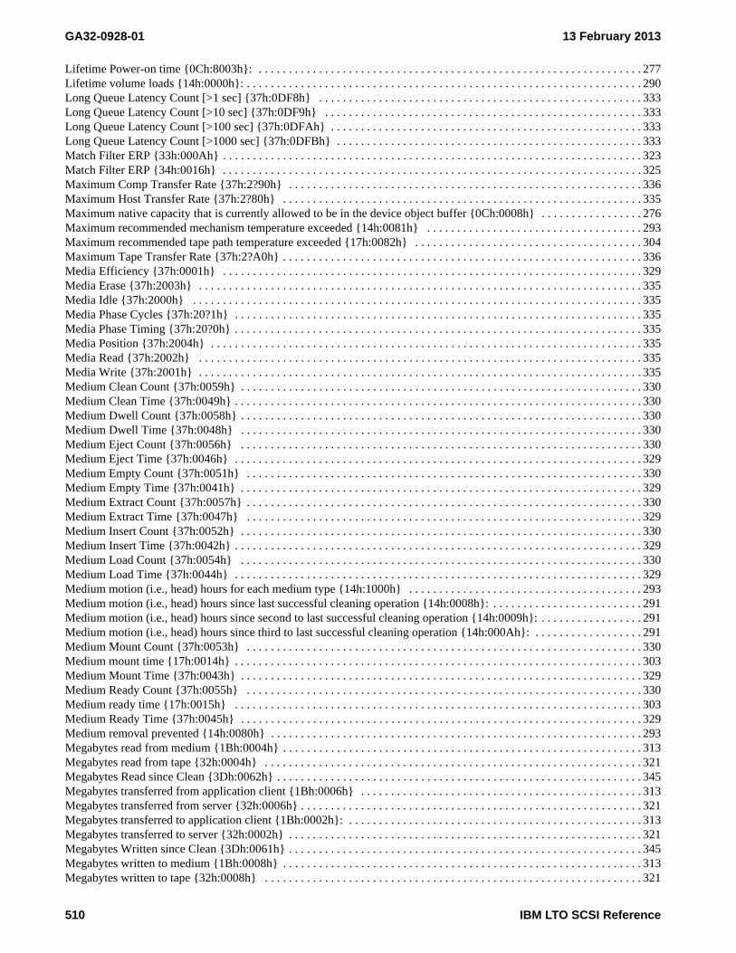
GA32-0928-01 13 February 2013
Lifetime Power-on time {0Ch:8003h}: . . . . . . . . . . . . . . . . . . . . . . . . . . . . . . . . . . . . . . . . . . . . . . . . . . . . . . . . . . . . . . . . 277Lifetime volume loads {14h:0000h}: . . . . . . . . . . . . . . . . . . . . . . . . . . . . . . . . . . . . . . . . . . . . . . . . . . . . . . . . . . . . . . . . . . 290Long Queue Latency Count [>1 sec] {37h:0DF8h} . . . . . . . . . . . . . . . . . . . . . . . . . . . . . . . . . . . . . . . . . . . . . . . . . . . . . . 333Long Queue Latency Count [>10 sec] {37h:0DF9h} . . . . . . . . . . . . . . . . . . . . . . . . . . . . . . . . . . . . . . . . . . . . . . . . . . . . . 333Long Queue Latency Count [>100 sec] {37h:0DFAh} . . . . . . . . . . . . . . . . . . . . . . . . . . . . . . . . . . . . . . . . . . . . . . . . . . . . 333Long Queue Latency Count [>1000 sec] {37h:0DFBh} . . . . . . . . . . . . . . . . . . . . . . . . . . . . . . . . . . . . . . . . . . . . . . . . . . . 333Match Filter ERP {33h:000Ah} . . . . . . . . . . . . . . . . . . . . . . . . . . . . . . . . . . . . . . . . . . . . . . . . . . . . . . . . . . . . . . . . . . . . . . 323Match Filter ERP {34h:0016h} . . . . . . . . . . . . . . . . . . . . . . . . . . . . . . . . . . . . . . . . . . . . . . . . . . . . . . . . . . . . . . . . . . . . . . 325Maximum Comp Transfer Rate {37h:2?90h} . . . . . . . . . . . . . . . . . . . . . . . . . . . . . . . . . . . . . . . . . . . . . . . . . . . . . . . . . . . 336Maximum Host Transfer Rate {37h:2?80h} . . . . . . . . . . . . . . . . . . . . . . . . . . . . . . . . . . . . . . . . . . . . . . . . . . . . . . . . . . . . 335Maximum native capacity that is currently allowed to be in the device object buffer {0Ch:0008h} . . . . . . . . . . . . . . . . . 276Maximum recommended mechanism temperature exceeded {14h:0081h} . . . . . . . . . . . . . . . . . . . . . . . . . . . . . . . . . . . . 293Maximum recommended tape path temperature exceeded {17h:0082h} . . . . . . . . . . . . . . . . . . . . . . . . . . . . . . . . . . . . . . 304Maximum Tape Transfer Rate {37h:2?A0h} . . . . . . . . . . . . . . . . . . . . . . . . . . . . . . . . . . . . . . . . . . . . . . . . . . . . . . . . . . . . 336Media Efficiency {37h:0001h} . . . . . . . . . . . . . . . . . . . . . . . . . . . . . . . . . . . . . . . . . . . . . . . . . . . . . . . . . . . . . . . . . . . . . . 329Media Erase {37h:2003h} . . . . . . . . . . . . . . . . . . . . . . . . . . . . . . . . . . . . . . . . . . . . . . . . . . . . . . . . . . . . . . . . . . . . . . . . . . 335Media Idle {37h:2000h} . . . . . . . . . . . . . . . . . . . . . . . . . . . . . . . . . . . . . . . . . . . . . . . . . . . . . . . . . . . . . . . . . . . . . . . . . . . 335Media Phase Cycles {37h:20?1h} . . . . . . . . . . . . . . . . . . . . . . . . . . . . . . . . . . . . . . . . . . . . . . . . . . . . . . . . . . . . . . . . . . . . 335Media Phase Timing {37h:20?0h} . . . . . . . . . . . . . . . . . . . . . . . . . . . . . . . . . . . . . . . . . . . . . . . . . . . . . . . . . . . . . . . . . . . . 335Media Position {37h:2004h} . . . . . . . . . . . . . . . . . . . . . . . . . . . . . . . . . . . . . . . . . . . . . . . . . . . . . . . . . . . . . . . . . . . . . . . . 335Media Read {37h:2002h} . . . . . . . . . . . . . . . . . . . . . . . . . . . . . . . . . . . . . . . . . . . . . . . . . . . . . . . . . . . . . . . . . . . . . . . . . . 335Media Write {37h:2001h} . . . . . . . . . . . . . . . . . . . . . . . . . . . . . . . . . . . . . . . . . . . . . . . . . . . . . . . . . . . . . . . . . . . . . . . . . . 335Medium Clean Count {37h:0059h} . . . . . . . . . . . . . . . . . . . . . . . . . . . . . . . . . . . . . . . . . . . . . . . . . . . . . . . . . . . . . . . . . . . 330Medium Clean Time {37h:0049h} . . . . . . . . . . . . . . . . . . . . . . . . . . . . . . . . . . . . . . . . . . . . . . . . . . . . . . . . . . . . . . . . . . . . 330Medium Dwell Count {37h:0058h} . . . . . . . . . . . . . . . . . . . . . . . . . . . . . . . . . . . . . . . . . . . . . . . . . . . . . . . . . . . . . . . . . . . 330Medium Dwell Time {37h:0048h} . . . . . . . . . . . . . . . . . . . . . . . . . . . . . . . . . . . . . . . . . . . . . . . . . . . . . . . . . . . . . . . . . . . 330Medium Eject Count {37h:0056h} . . . . . . . . . . . . . . . . . . . . . . . . . . . . . . . . . . . . . . . . . . . . . . . . . . . . . . . . . . . . . . . . . . . 330Medium Eject Time {37h:0046h} . . . . . . . . . . . . . . . . . . . . . . . . . . . . . . . . . . . . . . . . . . . . . . . . . . . . . . . . . . . . . . . . . . . . 329Medium Empty Count {37h:0051h} . . . . . . . . . . . . . . . . . . . . . . . . . . . . . . . . . . . . . . . . . . . . . . . . . . . . . . . . . . . . . . . . . . 330Medium Empty Time {37h:0041h} . . . . . . . . . . . . . . . . . . . . . . . . . . . . . . . . . . . . . . . . . . . . . . . . . . . . . . . . . . . . . . . . . . . 329Medium Extract Count {37h:0057h} . . . . . . . . . . . . . . . . . . . . . . . . . . . . . . . . . . . . . . . . . . . . . . . . . . . . . . . . . . . . . . . . . . 330Medium Extract Time {37h:0047h} . . . . . . . . . . . . . . . . . . . . . . . . . . . . . . . . . . . . . . . . . . . . . . . . . . . . . . . . . . . . . . . . . . 329Medium Insert Count {37h:0052h} . . . . . . . . . . . . . . . . . . . . . . . . . . . . . . . . . . . . . . . . . . . . . . . . . . . . . . . . . . . . . . . . . . . 330Medium Insert Time {37h:0042h} . . . . . . . . . . . . . . . . . . . . . . . . . . . . . . . . . . . . . . . . . . . . . . . . . . . . . . . . . . . . . . . . . . . . 329Medium Load Count {37h:0054h} . . . . . . . . . . . . . . . . . . . . . . . . . . . . . . . . . . . . . . . . . . . . . . . . . . . . . . . . . . . . . . . . . . . 330Medium Load Time {37h:0044h} . . . . . . . . . . . . . . . . . . . . . . . . . . . . . . . . . . . . . . . . . . . . . . . . . . . . . . . . . . . . . . . . . . . . 329Medium motion (i.e., head) hours for each medium type {14h:1000h} . . . . . . . . . . . . . . . . . . . . . . . . . . . . . . . . . . . . . . . 293Medium motion (i.e., head) hours since last successful cleaning operation {14h:0008h}: . . . . . . . . . . . . . . . . . . . . . . . . . 291Medium motion (i.e., head) hours since second to last successful cleaning operation {14h:0009h}: . . . . . . . . . . . . . . . . . 291Medium motion (i.e., head) hours since third to last successful cleaning operation {14h:000Ah}: . . . . . . . . . . . . . . . . . . 291Medium Mount Count {37h:0053h} . . . . . . . . . . . . . . . . . . . . . . . . . . . . . . . . . . . . . . . . . . . . . . . . . . . . . . . . . . . . . . . . . . 330Medium mount time {17h:0014h} . . . . . . . . . . . . . . . . . . . . . . . . . . . . . . . . . . . . . . . . . . . . . . . . . . . . . . . . . . . . . . . . . . . . 303Medium Mount Time {37h:0043h} . . . . . . . . . . . . . . . . . . . . . . . . . . . . . . . . . . . . . . . . . . . . . . . . . . . . . . . . . . . . . . . . . . . 329Medium Ready Count {37h:0055h} . . . . . . . . . . . . . . . . . . . . . . . . . . . . . . . . . . . . . . . . . . . . . . . . . . . . . . . . . . . . . . . . . . 330Medium ready time {17h:0015h} . . . . . . . . . . . . . . . . . . . . . . . . . . . . . . . . . . . . . . . . . . . . . . . . . . . . . . . . . . . . . . . . . . . . 303Medium Ready Time {37h:0045h} . . . . . . . . . . . . . . . . . . . . . . . . . . . . . . . . . . . . . . . . . . . . . . . . . . . . . . . . . . . . . . . . . . . 329Medium removal prevented {14h:0080h} . . . . . . . . . . . . . . . . . . . . . . . . . . . . . . . . . . . . . . . . . . . . . . . . . . . . . . . . . . . . . . 293Megabytes read from medium {1Bh:0004h} . . . . . . . . . . . . . . . . . . . . . . . . . . . . . . . . . . . . . . . . . . . . . . . . . . . . . . . . . . . . 313Megabytes read from tape {32h:0004h} . . . . . . . . . . . . . . . . . . . . . . . . . . . . . . . . . . . . . . . . . . . . . . . . . . . . . . . . . . . . . . . 321Megabytes Read since Clean {3Dh:0062h} . . . . . . . . . . . . . . . . . . . . . . . . . . . . . . . . . . . . . . . . . . . . . . . . . . . . . . . . . . . . . 345Megabytes transferred from application client {1Bh:0006h} . . . . . . . . . . . . . . . . . . . . . . . . . . . . . . . . . . . . . . . . . . . . . . . 313Megabytes transferred from server {32h:0006h} . . . . . . . . . . . . . . . . . . . . . . . . . . . . . . . . . . . . . . . . . . . . . . . . . . . . . . . . . 321Megabytes transferred to application client {1Bh:0002h}: . . . . . . . . . . . . . . . . . . . . . . . . . . . . . . . . . . . . . . . . . . . . . . . . . 313Megabytes transferred to server {32h:0002h} . . . . . . . . . . . . . . . . . . . . . . . . . . . . . . . . . . . . . . . . . . . . . . . . . . . . . . . . . . . 321Megabytes Written since Clean {3Dh:0061h} . . . . . . . . . . . . . . . . . . . . . . . . . . . . . . . . . . . . . . . . . . . . . . . . . . . . . . . . . . . 345Megabytes written to medium {1Bh:0008h} . . . . . . . . . . . . . . . . . . . . . . . . . . . . . . . . . . . . . . . . . . . . . . . . . . . . . . . . . . . . 313Megabytes written to tape {32h:0008h} . . . . . . . . . . . . . . . . . . . . . . . . . . . . . . . . . . . . . . . . . . . . . . . . . . . . . . . . . . . . . . . 321
510 IBM LTO SCSI Reference

13 February 2013 GA32-0928-01
Middle of tape passes {17h:0102h} . . . . . . . . . . . . . . . . . . . . . . . . . . . . . . . . . . . . . . . . . . . . . . . . . . . . . . . . . . . . . . . . . . . 304Minimum native capacity between EW and LEOP of the current partition {0Ch:0006h} . . . . . . . . . . . . . . . . . . . . . . . . . 276Mounts since Clean {3Dh:0063h} . . . . . . . . . . . . . . . . . . . . . . . . . . . . . . . . . . . . . . . . . . . . . . . . . . . . . . . . . . . . . . . . . . . . 346Moving Tape Buffer Efficiency {37h:2?A5h} . . . . . . . . . . . . . . . . . . . . . . . . . . . . . . . . . . . . . . . . . . . . . . . . . . . . . . . . . . . 336Moving Tape Buffer Rate {37h:2?A3h} . . . . . . . . . . . . . . . . . . . . . . . . . . . . . . . . . . . . . . . . . . . . . . . . . . . . . . . . . . . . . . . 336Nominal Capacity of Partition {38h:000Ch} . . . . . . . . . . . . . . . . . . . . . . . . . . . . . . . . . . . . . . . . . . . . . . . . . . . . . . . . . . . . 338Nominal Capacity of Volume {38h:000Eh} . . . . . . . . . . . . . . . . . . . . . . . . . . . . . . . . . . . . . . . . . . . . . . . . . . . . . . . . . . . . 339Number of mounts for the current volume . . . . . . . . . . . . . . . . . . . . . . . . . . . . . . . . . . . . . . . . . . . . . . . . . . . . . . . . . . . . . . 319Padded Data (Medium) {37h:2?72h} . . . . . . . . . . . . . . . . . . . . . . . . . . . . . . . . . . . . . . . . . . . . . . . . . . . . . . . . . . . . . . . . . . 335Padded Data {37h:2?62h} . . . . . . . . . . . . . . . . . . . . . . . . . . . . . . . . . . . . . . . . . . . . . . . . . . . . . . . . . . . . . . . . . . . . . . . . . . 335Page valid {17h:000h} . . . . . . . . . . . . . . . . . . . . . . . . . . . . . . . . . . . . . . . . . . . . . . . . . . . . . . . . . . . . . . . . . . . . . . . . . . . . . 302Partition 0 Maximum Capacity {31h:0003h} . . . . . . . . . . . . . . . . . . . . . . . . . . . . . . . . . . . . . . . . . . . . . . . . . . . . . . . . . . . 320Partition 0 Remaining Capacity {31h:0001h} . . . . . . . . . . . . . . . . . . . . . . . . . . . . . . . . . . . . . . . . . . . . . . . . . . . . . . . . . . . 320Partition 1 Maximum Capacity {31h:0004h} . . . . . . . . . . . . . . . . . . . . . . . . . . . . . . . . . . . . . . . . . . . . . . . . . . . . . . . . . . . 320Partition 1 Remaining Capacity {31h:0002h} . . . . . . . . . . . . . . . . . . . . . . . . . . . . . . . . . . . . . . . . . . . . . . . . . . . . . . . . . . . 320Performance Impact by ERPs {37h:2?52h} . . . . . . . . . . . . . . . . . . . . . . . . . . . . . . . . . . . . . . . . . . . . . . . . . . . . . . . . . . . . . 335Performance Impacting ERPs {37h:2?51h} . . . . . . . . . . . . . . . . . . . . . . . . . . . . . . . . . . . . . . . . . . . . . . . . . . . . . . . . . . . . . 335Port Rate Changes {37h:0Dp7h} . . . . . . . . . . . . . . . . . . . . . . . . . . . . . . . . . . . . . . . . . . . . . . . . . . . . . . . . . . . . . . . . . . . . . 333Port Throughput Efficiency {37h:0Dp4h} . . . . . . . . . . . . . . . . . . . . . . . . . . . . . . . . . . . . . . . . . . . . . . . . . . . . . . . . . . . . . . 333Port Throughput Rate {37h:0Dp3h} . . . . . . . . . . . . . . . . . . . . . . . . . . . . . . . . . . . . . . . . . . . . . . . . . . . . . . . . . . . . . . . . . . 333Port Throughput Rate Maximum Bursting {37h:0Dp1h} . . . . . . . . . . . . . . . . . . . . . . . . . . . . . . . . . . . . . . . . . . . . . . . . . . 333Port Throughput Rate Maximum Sustained {37h:0Dp2h} . . . . . . . . . . . . . . . . . . . . . . . . . . . . . . . . . . . . . . . . . . . . . . . . . 333Position Buffer Hits {37h:14F0h} . . . . . . . . . . . . . . . . . . . . . . . . . . . . . . . . . . . . . . . . . . . . . . . . . . . . . . . . . . . . . . . . . . . . 335Position Count (Media) {37h:1480h} . . . . . . . . . . . . . . . . . . . . . . . . . . . . . . . . . . . . . . . . . . . . . . . . . . . . . . . . . . . . . . . . . 334Position Count {37h:1400h} . . . . . . . . . . . . . . . . . . . . . . . . . . . . . . . . . . . . . . . . . . . . . . . . . . . . . . . . . . . . . . . . . . . . . . . . 334Position Relative Rate (Media) {37h:14B0h} . . . . . . . . . . . . . . . . . . . . . . . . . . . . . . . . . . . . . . . . . . . . . . . . . . . . . . . . . . . 334Position Relative Rate {37h:1430h} . . . . . . . . . . . . . . . . . . . . . . . . . . . . . . . . . . . . . . . . . . . . . . . . . . . . . . . . . . . . . . . . . . 334Position Relative Time (Media) {37h:14A0h} . . . . . . . . . . . . . . . . . . . . . . . . . . . . . . . . . . . . . . . . . . . . . . . . . . . . . . . . . . 334Position Relative Time {37h:1420h} . . . . . . . . . . . . . . . . . . . . . . . . . . . . . . . . . . . . . . . . . . . . . . . . . . . . . . . . . . . . . . . . . . 334Position Time (Media) {37h:1490h} . . . . . . . . . . . . . . . . . . . . . . . . . . . . . . . . . . . . . . . . . . . . . . . . . . . . . . . . . . . . . . . . . . 334Position Time {37h:1410h} . . . . . . . . . . . . . . . . . . . . . . . . . . . . . . . . . . . . . . . . . . . . . . . . . . . . . . . . . . . . . . . . . . . . . . . . . 334Power On Seconds {3Dh:0101h} . . . . . . . . . . . . . . . . . . . . . . . . . . . . . . . . . . . . . . . . . . . . . . . . . . . . . . . . . . . . . . . . . . . . . 346Primary Initiator {37h:0E01h} . . . . . . . . . . . . . . . . . . . . . . . . . . . . . . . . . . . . . . . . . . . . . . . . . . . . . . . . . . . . . . . . . . . . . . . 333Primary Interface Efficiency {37h:0010h} . . . . . . . . . . . . . . . . . . . . . . . . . . . . . . . . . . . . . . . . . . . . . . . . . . . . . . . . . . . . . 329Primary Interface Port 0 Efficiency {37h:0011h} . . . . . . . . . . . . . . . . . . . . . . . . . . . . . . . . . . . . . . . . . . . . . . . . . . . . . . . . 329Primary Interface Port 1 Efficiency {37h:0012j} . . . . . . . . . . . . . . . . . . . . . . . . . . . . . . . . . . . . . . . . . . . . . . . . . . . . . . . . 329Read Compression ratio {1Bh:0000h} . . . . . . . . . . . . . . . . . . . . . . . . . . . . . . . . . . . . . . . . . . . . . . . . . . . . . . . . . . . . . . . . . 313Read Compression ratio x 100 {32h:0000h} . . . . . . . . . . . . . . . . . . . . . . . . . . . . . . . . . . . . . . . . . . . . . . . . . . . . . . . . . . . . 321Read Count {37h:0300h} . . . . . . . . . . . . . . . . . . . . . . . . . . . . . . . . . . . . . . . . . . . . . . . . . . . . . . . . . . . . . . . . . . . . . . . . . . . 330Read Cycle Relative Time {37h:1220h} . . . . . . . . . . . . . . . . . . . . . . . . . . . . . . . . . . . . . . . . . . . . . . . . . . . . . . . . . . . . . . . 334Read Cycle Time {37h:1210h} . . . . . . . . . . . . . . . . . . . . . . . . . . . . . . . . . . . . . . . . . . . . . . . . . . . . . . . . . . . . . . . . . . . . . . 334Read Cycles {37h:1200h} . . . . . . . . . . . . . . . . . . . . . . . . . . . . . . . . . . . . . . . . . . . . . . . . . . . . . . . . . . . . . . . . . . . . . . . . . . 334Read duty cycle {14h:0011h} . . . . . . . . . . . . . . . . . . . . . . . . . . . . . . . . . . . . . . . . . . . . . . . . . . . . . . . . . . . . . . . . . . . . . . . 292Read Exit Relative Time {37h:1224h} . . . . . . . . . . . . . . . . . . . . . . . . . . . . . . . . . . . . . . . . . . . . . . . . . . . . . . . . . . . . . . . . 334Read Filemark (perf) Relative Time {37h:03D4h} . . . . . . . . . . . . . . . . . . . . . . . . . . . . . . . . . . . . . . . . . . . . . . . . . . . . . . . 331Read Media Blocks Counter {3Ch:0003h} . . . . . . . . . . . . . . . . . . . . . . . . . . . . . . . . . . . . . . . . . . . . . . . . . . . . . . . . . . . . . 343Read Pause Relative Time {37h:1223h} . . . . . . . . . . . . . . . . . . . . . . . . . . . . . . . . . . . . . . . . . . . . . . . . . . . . . . . . . . . . . . . 334Read Pauses {37h:1201h} . . . . . . . . . . . . . . . . . . . . . . . . . . . . . . . . . . . . . . . . . . . . . . . . . . . . . . . . . . . . . . . . . . . . . . . . . . 334Read Performance Efficiency {37h:03D0h} . . . . . . . . . . . . . . . . . . . . . . . . . . . . . . . . . . . . . . . . . . . . . . . . . . . . . . . . . . . . 331Read Ready Relative Time {37h:1222h} . . . . . . . . . . . . . . . . . . . . . . . . . . . . . . . . . . . . . . . . . . . . . . . . . . . . . . . . . . . . . . . 334Read Relative Time {37h:0302h} . . . . . . . . . . . . . . . . . . . . . . . . . . . . . . . . . . . . . . . . . . . . . . . . . . . . . . . . . . . . . . . . . . . . 331Read Setup Relative Time {37h:1221h} . . . . . . . . . . . . . . . . . . . . . . . . . . . . . . . . . . . . . . . . . . . . . . . . . . . . . . . . . . . . . . . 334Read Timing {37h:0301h} . . . . . . . . . . . . . . . . . . . . . . . . . . . . . . . . . . . . . . . . . . . . . . . . . . . . . . . . . . . . . . . . . . . . . . . . . . 331Read Traverse EM Relative Time {37h:1225h} . . . . . . . . . . . . . . . . . . . . . . . . . . . . . . . . . . . . . . . . . . . . . . . . . . . . . . . . . 334Ready duty cycle {14h:0015h} . . . . . . . . . . . . . . . . . . . . . . . . . . . . . . . . . . . . . . . . . . . . . . . . . . . . . . . . . . . . . . . . . . . . . . 292Relative Time {37h:0q01h} . . . . . . . . . . . . . . . . . . . . . . . . . . . . . . . . . . . . . . . . . . . . . . . . . . . . . . . . . . . . . . . . . . . . . . . . . 330Remaining Capacity of Partition {38h:0011h} . . . . . . . . . . . . . . . . . . . . . . . . . . . . . . . . . . . . . . . . . . . . . . . . . . . . . . . . . . 339
IBM LTO SCSI Reference 511

GA32-0928-01 13 February 2013
Remaining Capacity of Volume {38h:0010h} . . . . . . . . . . . . . . . . . . . . . . . . . . . . . . . . . . . . . . . . . . . . . . . . . . . . . . . . . . . 339Reread Media Blocks Counter {3Ch:0005h} . . . . . . . . . . . . . . . . . . . . . . . . . . . . . . . . . . . . . . . . . . . . . . . . . . . . . . . . . . . . 343Reset Count [by port] {37h:0Fp3h} . . . . . . . . . . . . . . . . . . . . . . . . . . . . . . . . . . . . . . . . . . . . . . . . . . . . . . . . . . . . . . . . . . . 334Reset Seconds {3Dh:0102h} . . . . . . . . . . . . . . . . . . . . . . . . . . . . . . . . . . . . . . . . . . . . . . . . . . . . . . . . . . . . . . . . . . . . . . . . 346Resource Recoveries [by port] {37h:0Fp2h} . . . . . . . . . . . . . . . . . . . . . . . . . . . . . . . . . . . . . . . . . . . . . . . . . . . . . . . . . . . . 334Rewrite Media Blocks Counter {3Ch:0002h} . . . . . . . . . . . . . . . . . . . . . . . . . . . . . . . . . . . . . . . . . . . . . . . . . . . . . . . . . . . 343Secondary Initiator {37h:0E02h} . . . . . . . . . . . . . . . . . . . . . . . . . . . . . . . . . . . . . . . . . . . . . . . . . . . . . . . . . . . . . . . . . . . . . 333Seek Block Count {37h:06D1h} . . . . . . . . . . . . . . . . . . . . . . . . . . . . . . . . . . . . . . . . . . . . . . . . . . . . . . . . . . . . . . . . . . . . . 332Seek Count {37h:0600h} . . . . . . . . . . . . . . . . . . . . . . . . . . . . . . . . . . . . . . . . . . . . . . . . . . . . . . . . . . . . . . . . . . . . . . . . . . . 332Seek Relative Time {37h:0602h} . . . . . . . . . . . . . . . . . . . . . . . . . . . . . . . . . . . . . . . . . . . . . . . . . . . . . . . . . . . . . . . . . . . . 332Seek Timing {37h:0601h} . . . . . . . . . . . . . . . . . . . . . . . . . . . . . . . . . . . . . . . . . . . . . . . . . . . . . . . . . . . . . . . . . . . . . . . . . . 332Sequence Errors {34h:0008h} . . . . . . . . . . . . . . . . . . . . . . . . . . . . . . . . . . . . . . . . . . . . . . . . . . . . . . . . . . . . . . . . . . . . . . . 324Servo Acquisition Temps {33h:0004h} . . . . . . . . . . . . . . . . . . . . . . . . . . . . . . . . . . . . . . . . . . . . . . . . . . . . . . . . . . . . . . . . 322Servo Acquisition Temps {34h:0004h} . . . . . . . . . . . . . . . . . . . . . . . . . . . . . . . . . . . . . . . . . . . . . . . . . . . . . . . . . . . . . . . . 324Servo AGA Gain ERP {34h:0010h} . . . . . . . . . . . . . . . . . . . . . . . . . . . . . . . . . . . . . . . . . . . . . . . . . . . . . . . . . . . . . . . . . . 325Servo Opposite Gap ERP {34h:0012h} . . . . . . . . . . . . . . . . . . . . . . . . . . . . . . . . . . . . . . . . . . . . . . . . . . . . . . . . . . . . . . . . 325Servo Position Events {33h:0011h} . . . . . . . . . . . . . . . . . . . . . . . . . . . . . . . . . . . . . . . . . . . . . . . . . . . . . . . . . . . . . . . . . . . 323Servo Position Events {34h:001Eh} . . . . . . . . . . . . . . . . . . . . . . . . . . . . . . . . . . . . . . . . . . . . . . . . . . . . . . . . . . . . . . . . . . 325Servo Skip Events {33h:000Bh} . . . . . . . . . . . . . . . . . . . . . . . . . . . . . . . . . . . . . . . . . . . . . . . . . . . . . . . . . . . . . . . . . . . . . 323Servo Skip Events {34h:001Bh} . . . . . . . . . . . . . . . . . . . . . . . . . . . . . . . . . . . . . . . . . . . . . . . . . . . . . . . . . . . . . . . . . . . . . 325Servo Speed Relative Time {37h:5Fs0h} . . . . . . . . . . . . . . . . . . . . . . . . . . . . . . . . . . . . . . . . . . . . . . . . . . . . . . . . . . . . . . 336Servo Temps {33h:0006h} . . . . . . . . . . . . . . . . . . . . . . . . . . . . . . . . . . . . . . . . . . . . . . . . . . . . . . . . . . . . . . . . . . . . . . . . . . 322Servo Temps {34h:0006h} . . . . . . . . . . . . . . . . . . . . . . . . . . . . . . . . . . . . . . . . . . . . . . . . . . . . . . . . . . . . . . . . . . . . . . . . . . 324Servo Transients {33h:0001h} . . . . . . . . . . . . . . . . . . . . . . . . . . . . . . . . . . . . . . . . . . . . . . . . . . . . . . . . . . . . . . . . . . . . . . . 322Servo Transients {34h:0001h} . . . . . . . . . . . . . . . . . . . . . . . . . . . . . . . . . . . . . . . . . . . . . . . . . . . . . . . . . . . . . . . . . . . . . . . 324Speed Changes {37h:2?F0h} . . . . . . . . . . . . . . . . . . . . . . . . . . . . . . . . . . . . . . . . . . . . . . . . . . . . . . . . . . . . . . . . . . . . . . . . 336Speed Forced {37h:2?F1h} . . . . . . . . . . . . . . . . . . . . . . . . . . . . . . . . . . . . . . . . . . . . . . . . . . . . . . . . . . . . . . . . . . . . . . . . . 336Static Capacity Efficiency (Partition t) {37h:8t00h} . . . . . . . . . . . . . . . . . . . . . . . . . . . . . . . . . . . . . . . . . . . . . . . . . . . . . . 337Static Capacity Efficiency {37h:7000h} . . . . . . . . . . . . . . . . . . . . . . . . . . . . . . . . . . . . . . . . . . . . . . . . . . . . . . . . . . . . . . . 337Static Datasets Media (Partition t) {37h:8t10h} . . . . . . . . . . . . . . . . . . . . . . . . . . . . . . . . . . . . . . . . . . . . . . . . . . . . . . . . . 337Static Datasets Media {37h:7010h} . . . . . . . . . . . . . . . . . . . . . . . . . . . . . . . . . . . . . . . . . . . . . . . . . . . . . . . . . . . . . . . . . . . 337Static Datasets Used (Partition t) {37h:8t11h} . . . . . . . . . . . . . . . . . . . . . . . . . . . . . . . . . . . . . . . . . . . . . . . . . . . . . . . . . . 337Static Datasets Used {37h:7011h} . . . . . . . . . . . . . . . . . . . . . . . . . . . . . . . . . . . . . . . . . . . . . . . . . . . . . . . . . . . . . . . . . . . . 337Static Distance Media (Partition t) {37h:8t20h} . . . . . . . . . . . . . . . . . . . . . . . . . . . . . . . . . . . . . . . . . . . . . . . . . . . . . . . . . 337Static Distance Media {37h:7020h} . . . . . . . . . . . . . . . . . . . . . . . . . . . . . . . . . . . . . . . . . . . . . . . . . . . . . . . . . . . . . . . . . . . 337Static Distance Used (Partition t) {37h:8t21h} . . . . . . . . . . . . . . . . . . . . . . . . . . . . . . . . . . . . . . . . . . . . . . . . . . . . . . . . . . 337Static Distance Used {37h:7021h} . . . . . . . . . . . . . . . . . . . . . . . . . . . . . . . . . . . . . . . . . . . . . . . . . . . . . . . . . . . . . . . . . . . . 337Static Remaining Capacity in SkipSync Buffer {37h:7030h} . . . . . . . . . . . . . . . . . . . . . . . . . . . . . . . . . . . . . . . . . . . . . . . 337Sync Count [Host] {37h:0500h} . . . . . . . . . . . . . . . . . . . . . . . . . . . . . . . . . . . . . . . . . . . . . . . . . . . . . . . . . . . . . . . . . . . . . 331Sync Count [Implicit] {37h:05D1h} . . . . . . . . . . . . . . . . . . . . . . . . . . . . . . . . . . . . . . . . . . . . . . . . . . . . . . . . . . . . . . . . . . 332Sync Relative Time [Host] {37h:0502h} . . . . . . . . . . . . . . . . . . . . . . . . . . . . . . . . . . . . . . . . . . . . . . . . . . . . . . . . . . . . . . . 332Sync Relative Time [Implicit] {37h:05D4h} . . . . . . . . . . . . . . . . . . . . . . . . . . . . . . . . . . . . . . . . . . . . . . . . . . . . . . . . . . . . 332Sync Timing [Host] {37h:0501h} . . . . . . . . . . . . . . . . . . . . . . . . . . . . . . . . . . . . . . . . . . . . . . . . . . . . . . . . . . . . . . . . . . . . 332Sync Timing [Implicit] {37h:05D2h} . . . . . . . . . . . . . . . . . . . . . . . . . . . . . . . . . . . . . . . . . . . . . . . . . . . . . . . . . . . . . . . . . 332Tape Buffer Efficiency {37h:2?A6h} . . . . . . . . . . . . . . . . . . . . . . . . . . . . . . . . . . . . . . . . . . . . . . . . . . . . . . . . . . . . . . . . . 336Tape Efficiency {37h:2?A8h} . . . . . . . . . . . . . . . . . . . . . . . . . . . . . . . . . . . . . . . . . . . . . . . . . . . . . . . . . . . . . . . . . . . . . . . 336Tape lot identifier {17h:0041h} . . . . . . . . . . . . . . . . . . . . . . . . . . . . . . . . . . . . . . . . . . . . . . . . . . . . . . . . . . . . . . . . . . . . . . 303Tape Thrashing {37h:2?A7h} . . . . . . . . . . . . . . . . . . . . . . . . . . . . . . . . . . . . . . . . . . . . . . . . . . . . . . . . . . . . . . . . . . . . . . . 336Time {37h:0040h} . . . . . . . . . . . . . . . . . . . . . . . . . . . . . . . . . . . . . . . . . . . . . . . . . . . . . . . . . . . . . . . . . . . . . . . . . . . . . . . . 329Time Since Last Cleaning Counter {3Ch:0007h} . . . . . . . . . . . . . . . . . . . . . . . . . . . . . . . . . . . . . . . . . . . . . . . . . . . . . . . . 344Timing {37h:0q01h} . . . . . . . . . . . . . . . . . . . . . . . . . . . . . . . . . . . . . . . . . . . . . . . . . . . . . . . . . . . . . . . . . . . . . . . . . . . . . . 330Total Channel Read Bytes {0Ch:0003h}: . . . . . . . . . . . . . . . . . . . . . . . . . . . . . . . . . . . . . . . . . . . . . . . . . . . . . . . . . . . . . . 276Total Channel Write Bytes {0Ch:0000h}: . . . . . . . . . . . . . . . . . . . . . . . . . . . . . . . . . . . . . . . . . . . . . . . . . . . . . . . . . . . . . . 276Total Corrected Read Errors {03h:0003h} . . . . . . . . . . . . . . . . . . . . . . . . . . . . . . . . . . . . . . . . . . . . . . . . . . . . . . . . . . . . . . 274Total Corrected Write Errors {02h:0003h}: . . . . . . . . . . . . . . . . . . . . . . . . . . . . . . . . . . . . . . . . . . . . . . . . . . . . . . . . . . . . . 273Total Device Read Bytes {0Ch:0002h}: . . . . . . . . . . . . . . . . . . . . . . . . . . . . . . . . . . . . . . . . . . . . . . . . . . . . . . . . . . . . . . . 276Total Device Write Bytes {0Ch:0001h}: . . . . . . . . . . . . . . . . . . . . . . . . . . . . . . . . . . . . . . . . . . . . . . . . . . . . . . . . . . . . . . . 276
512 IBM LTO SCSI Reference

13 February 2013 GA32-0928-01
Total Megabytes Processed Since Cleaning {0Ch:8000h}: . . . . . . . . . . . . . . . . . . . . . . . . . . . . . . . . . . . . . . . . . . . . . . . . . 277Total native capacity {17h:0016h} . . . . . . . . . . . . . . . . . . . . . . . . . . . . . . . . . . . . . . . . . . . . . . . . . . . . . . . . . . . . . . . . . . . 303Total Non-Medium Error Count {06h:0000h}: . . . . . . . . . . . . . . . . . . . . . . . . . . . . . . . . . . . . . . . . . . . . . . . . . . . . . . . . . . 275Total Read Kebibytes Processed {03h:0005h} . . . . . . . . . . . . . . . . . . . . . . . . . . . . . . . . . . . . . . . . . . . . . . . . . . . . . . . . . . 274Total Read Retries {03h:0004h} . . . . . . . . . . . . . . . . . . . . . . . . . . . . . . . . . . . . . . . . . . . . . . . . . . . . . . . . . . . . . . . . . . . . . 274Total Retries {33h:0008h} . . . . . . . . . . . . . . . . . . . . . . . . . . . . . . . . . . . . . . . . . . . . . . . . . . . . . . . . . . . . . . . . . . . . . . . . . . 322Total Retries {34h:0015h} . . . . . . . . . . . . . . . . . . . . . . . . . . . . . . . . . . . . . . . . . . . . . . . . . . . . . . . . . . . . . . . . . . . . . . . . . . 325Total Uncorrected Read Errors {03h:0006h} . . . . . . . . . . . . . . . . . . . . . . . . . . . . . . . . . . . . . . . . . . . . . . . . . . . . . . . . . . . . 274Total Uncorrected Write Errors {02h:0006h}: . . . . . . . . . . . . . . . . . . . . . . . . . . . . . . . . . . . . . . . . . . . . . . . . . . . . . . . . . . . 273Total used native capacity {17h:0017h} . . . . . . . . . . . . . . . . . . . . . . . . . . . . . . . . . . . . . . . . . . . . . . . . . . . . . . . . . . . . . . . 303Total Write Kebibytes Processed {02h:0005h}: . . . . . . . . . . . . . . . . . . . . . . . . . . . . . . . . . . . . . . . . . . . . . . . . . . . . . . . . . 273Total Write Retries {02h:0004h}: . . . . . . . . . . . . . . . . . . . . . . . . . . . . . . . . . . . . . . . . . . . . . . . . . . . . . . . . . . . . . . . . . . . . 273Transfer Byte Count from Host (out) {37h:0409h} . . . . . . . . . . . . . . . . . . . . . . . . . . . . . . . . . . . . . . . . . . . . . . . . . . . . . . . 331Transfer Byte Count from Host (out) {37h:0q09h} . . . . . . . . . . . . . . . . . . . . . . . . . . . . . . . . . . . . . . . . . . . . . . . . . . . . . . . 330Transfer Byte Count to Host (in) {37h:0305h} . . . . . . . . . . . . . . . . . . . . . . . . . . . . . . . . . . . . . . . . . . . . . . . . . . . . . . . . . . 331Transfer Byte Count to Host (in) {37h:0405h} . . . . . . . . . . . . . . . . . . . . . . . . . . . . . . . . . . . . . . . . . . . . . . . . . . . . . . . . . . 331Transfer Byte Count to Host (in) {37h:0505h} . . . . . . . . . . . . . . . . . . . . . . . . . . . . . . . . . . . . . . . . . . . . . . . . . . . . . . . . . . 332Transfer Byte Count to Host (in) {37h:0605h} . . . . . . . . . . . . . . . . . . . . . . . . . . . . . . . . . . . . . . . . . . . . . . . . . . . . . . . . . . 332Transfer Byte Count to Host (in) {37h:0q05h} . . . . . . . . . . . . . . . . . . . . . . . . . . . . . . . . . . . . . . . . . . . . . . . . . . . . . . . . . . 330Transfer Count from Host (out) {37h:0408h} . . . . . . . . . . . . . . . . . . . . . . . . . . . . . . . . . . . . . . . . . . . . . . . . . . . . . . . . . . . 331Transfer Count from Host (out) {37h:0q08h} . . . . . . . . . . . . . . . . . . . . . . . . . . . . . . . . . . . . . . . . . . . . . . . . . . . . . . . . . . . 330Transfer Count to Host (in) {37h:0304h} . . . . . . . . . . . . . . . . . . . . . . . . . . . . . . . . . . . . . . . . . . . . . . . . . . . . . . . . . . . . . . 331Transfer Count to Host (in) {37h:0404h} . . . . . . . . . . . . . . . . . . . . . . . . . . . . . . . . . . . . . . . . . . . . . . . . . . . . . . . . . . . . . . 331Transfer Count to Host (in) {37h:0504h} . . . . . . . . . . . . . . . . . . . . . . . . . . . . . . . . . . . . . . . . . . . . . . . . . . . . . . . . . . . . . . 332Transfer Count to Host (in) {37h:0604h} . . . . . . . . . . . . . . . . . . . . . . . . . . . . . . . . . . . . . . . . . . . . . . . . . . . . . . . . . . . . . . 332Transfer Count to Host (in) {37h:0q04h} . . . . . . . . . . . . . . . . . . . . . . . . . . . . . . . . . . . . . . . . . . . . . . . . . . . . . . . . . . . . . . 330Transfer Recover Time [by port] {37h:0Fp1h} . . . . . . . . . . . . . . . . . . . . . . . . . . . . . . . . . . . . . . . . . . . . . . . . . . . . . . . . . . 334Transfer Recoveries [by port] {37h:0Fp0h} . . . . . . . . . . . . . . . . . . . . . . . . . . . . . . . . . . . . . . . . . . . . . . . . . . . . . . . . . . . . 334Transfer Timing from Host (out) {37h:040Ah} . . . . . . . . . . . . . . . . . . . . . . . . . . . . . . . . . . . . . . . . . . . . . . . . . . . . . . . . . . 331Transfer Timing from Host (out) {37h:0q0Ah} . . . . . . . . . . . . . . . . . . . . . . . . . . . . . . . . . . . . . . . . . . . . . . . . . . . . . . . . . . 330Transfer Timing to Host (in) {37h:0306h} . . . . . . . . . . . . . . . . . . . . . . . . . . . . . . . . . . . . . . . . . . . . . . . . . . . . . . . . . . . . . 331Transfer Timing to Host (in) {37h:0406h} . . . . . . . . . . . . . . . . . . . . . . . . . . . . . . . . . . . . . . . . . . . . . . . . . . . . . . . . . . . . . 331Transfer Timing to Host (in) {37h:0506h} . . . . . . . . . . . . . . . . . . . . . . . . . . . . . . . . . . . . . . . . . . . . . . . . . . . . . . . . . . . . . 332Transfer Timing to Host (in) {37h:0606h} . . . . . . . . . . . . . . . . . . . . . . . . . . . . . . . . . . . . . . . . . . . . . . . . . . . . . . . . . . . . . 332Transfer Timing to Host (in) {37h:0q06h} . . . . . . . . . . . . . . . . . . . . . . . . . . . . . . . . . . . . . . . . . . . . . . . . . . . . . . . . . . . . . 330Uncompressed Data {37h:2?60h} . . . . . . . . . . . . . . . . . . . . . . . . . . . . . . . . . . . . . . . . . . . . . . . . . . . . . . . . . . . . . . . . . . . . 335Velocity Events {33h:0003h} . . . . . . . . . . . . . . . . . . . . . . . . . . . . . . . . . . . . . . . . . . . . . . . . . . . . . . . . . . . . . . . . . . . . . . . 322Velocity Events {34h:0003h} . . . . . . . . . . . . . . . . . . . . . . . . . . . . . . . . . . . . . . . . . . . . . . . . . . . . . . . . . . . . . . . . . . . . . . . 324Vendor-Reserved . . . . . . . . . . . . . . . . . . . . . . . . . . . . . . . . . . . . . . . . . . . . . . . . . . . . . . . . . . . . . . . . . . . . . . . . . . . . . . . . . 325Vendor-Reserved (Blocks Lifted) {33h:000Eh} . . . . . . . . . . . . . . . . . . . . . . . . . . . . . . . . . . . . . . . . . . . . . . . . . . . . . . . . . 323Vendor-Reserved {34h:0009h} . . . . . . . . . . . . . . . . . . . . . . . . . . . . . . . . . . . . . . . . . . . . . . . . . . . . . . . . . . . . . . . . . . . . . . 324Vendor-Reserved {34h:000Ah} . . . . . . . . . . . . . . . . . . . . . . . . . . . . . . . . . . . . . . . . . . . . . . . . . . . . . . . . . . . . . . . . . . . . . . 324Vendor-Reserved {34h:000Bh} . . . . . . . . . . . . . . . . . . . . . . . . . . . . . . . . . . . . . . . . . . . . . . . . . . . . . . . . . . . . . . . . . . . . . . 325Vendor-Reserved {34h:000Eh} . . . . . . . . . . . . . . . . . . . . . . . . . . . . . . . . . . . . . . . . . . . . . . . . . . . . . . . . . . . . . . . . . . . . . . 325Vendor-Reserved {34h:000Fh} . . . . . . . . . . . . . . . . . . . . . . . . . . . . . . . . . . . . . . . . . . . . . . . . . . . . . . . . . . . . . . . . . . . . . . 325Vendor-Reserved {34h:0013h} . . . . . . . . . . . . . . . . . . . . . . . . . . . . . . . . . . . . . . . . . . . . . . . . . . . . . . . . . . . . . . . . . . . . . . 325Vendor-Reserved {34h:0018h} . . . . . . . . . . . . . . . . . . . . . . . . . . . . . . . . . . . . . . . . . . . . . . . . . . . . . . . . . . . . . . . . . . . . . . 325Very high frequency data: . . . . . . . . . . . . . . . . . . . . . . . . . . . . . . . . . . . . . . . . . . . . . . . . . . . . . . . . . . . . . . . . . . . . . . . . . . 278Very high frequency polling delay: . . . . . . . . . . . . . . . . . . . . . . . . . . . . . . . . . . . . . . . . . . . . . . . . . . . . . . . . . . . . . . . . . . . 278Volume barcode {17h:0042h} . . . . . . . . . . . . . . . . . . . . . . . . . . . . . . . . . . . . . . . . . . . . . . . . . . . . . . . . . . . . . . . . . . . . . . . 304Volume Datasets Read {17h:0007h} . . . . . . . . . . . . . . . . . . . . . . . . . . . . . . . . . . . . . . . . . . . . . . . . . . . . . . . . . . . . . . . . . . 302Volume Datasets Read {30h:0007h}: . . . . . . . . . . . . . . . . . . . . . . . . . . . . . . . . . . . . . . . . . . . . . . . . . . . . . . . . . . . . . . . . . 319Volume Datasets Written {17h:0002h} . . . . . . . . . . . . . . . . . . . . . . . . . . . . . . . . . . . . . . . . . . . . . . . . . . . . . . . . . . . . . . . . 302Volume Datasets Written {30h:0002h}: . . . . . . . . . . . . . . . . . . . . . . . . . . . . . . . . . . . . . . . . . . . . . . . . . . . . . . . . . . . . . . . 319Volume Fatal Suspended Reads {30h:000Bh}: . . . . . . . . . . . . . . . . . . . . . . . . . . . . . . . . . . . . . . . . . . . . . . . . . . . . . . . . . . 319Volume Fatal Suspended Writes {30h:0006h}: . . . . . . . . . . . . . . . . . . . . . . . . . . . . . . . . . . . . . . . . . . . . . . . . . . . . . . . . . . 319Volume license code {17h:0044h} . . . . . . . . . . . . . . . . . . . . . . . . . . . . . . . . . . . . . . . . . . . . . . . . . . . . . . . . . . . . . . . . . . . 304
IBM LTO SCSI Reference 513
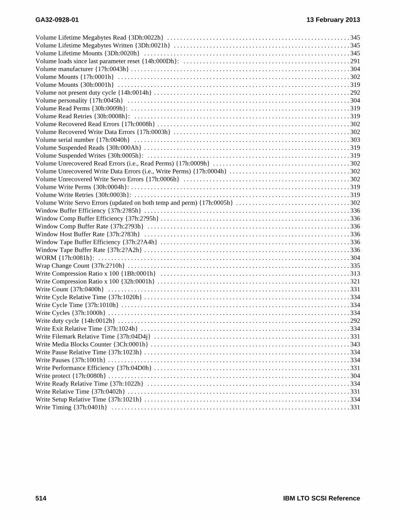
GA32-0928-01 13 February 2013
Volume Lifetime Megabytes Read {3Dh:0022h} . . . . . . . . . . . . . . . . . . . . . . . . . . . . . . . . . . . . . . . . . . . . . . . . . . . . . . . . 345Volume Lifetime Megabytes Written {3Dh:0021h} . . . . . . . . . . . . . . . . . . . . . . . . . . . . . . . . . . . . . . . . . . . . . . . . . . . . . . 345Volume Lifetime Mounts {3Dh:0020h} . . . . . . . . . . . . . . . . . . . . . . . . . . . . . . . . . . . . . . . . . . . . . . . . . . . . . . . . . . . . . . . 345Volume loads since last parameter reset {14h:000Dh}: . . . . . . . . . . . . . . . . . . . . . . . . . . . . . . . . . . . . . . . . . . . . . . . . . . . 291Volume manufacturer {17h:0043h} . . . . . . . . . . . . . . . . . . . . . . . . . . . . . . . . . . . . . . . . . . . . . . . . . . . . . . . . . . . . . . . . . . . 304Volume Mounts {17h:0001h} . . . . . . . . . . . . . . . . . . . . . . . . . . . . . . . . . . . . . . . . . . . . . . . . . . . . . . . . . . . . . . . . . . . . . . . 302Volume Mounts {30h:0001h} . . . . . . . . . . . . . . . . . . . . . . . . . . . . . . . . . . . . . . . . . . . . . . . . . . . . . . . . . . . . . . . . . . . . . . . 319Volume not present duty cycle {14h:0014h} . . . . . . . . . . . . . . . . . . . . . . . . . . . . . . . . . . . . . . . . . . . . . . . . . . . . . . . . . . . . 292Volume personality {17h:0045h} . . . . . . . . . . . . . . . . . . . . . . . . . . . . . . . . . . . . . . . . . . . . . . . . . . . . . . . . . . . . . . . . . . . . 304Volume Read Perms {30h:0009h}: . . . . . . . . . . . . . . . . . . . . . . . . . . . . . . . . . . . . . . . . . . . . . . . . . . . . . . . . . . . . . . . . . . . 319Volume Read Retries {30h:0008h}: . . . . . . . . . . . . . . . . . . . . . . . . . . . . . . . . . . . . . . . . . . . . . . . . . . . . . . . . . . . . . . . . . . 319Volume Recovered Read Errors {17h:0008h} . . . . . . . . . . . . . . . . . . . . . . . . . . . . . . . . . . . . . . . . . . . . . . . . . . . . . . . . . . . 302Volume Recovered Write Data Errors {17h:0003h} . . . . . . . . . . . . . . . . . . . . . . . . . . . . . . . . . . . . . . . . . . . . . . . . . . . . . . 302Volume serial number {17h:0040h} . . . . . . . . . . . . . . . . . . . . . . . . . . . . . . . . . . . . . . . . . . . . . . . . . . . . . . . . . . . . . . . . . . 303Volume Suspended Reads {30h:000Ah} . . . . . . . . . . . . . . . . . . . . . . . . . . . . . . . . . . . . . . . . . . . . . . . . . . . . . . . . . . . . . . . 319Volume Suspended Writes {30h:0005h}: . . . . . . . . . . . . . . . . . . . . . . . . . . . . . . . . . . . . . . . . . . . . . . . . . . . . . . . . . . . . . . 319Volume Unrecovered Read Errors (i.e., Read Perms) {17h:0009h} . . . . . . . . . . . . . . . . . . . . . . . . . . . . . . . . . . . . . . . . . . 302Volume Unrecovered Write Data Errors (i.e., Write Perms) {17h:0004h} . . . . . . . . . . . . . . . . . . . . . . . . . . . . . . . . . . . . . 302Volume Unrecovered Write Servo Errors {17h:0006h} . . . . . . . . . . . . . . . . . . . . . . . . . . . . . . . . . . . . . . . . . . . . . . . . . . . 302Volume Write Perms {30h:0004h}: . . . . . . . . . . . . . . . . . . . . . . . . . . . . . . . . . . . . . . . . . . . . . . . . . . . . . . . . . . . . . . . . . . . 319Volume Write Retries {30h:0003h}: . . . . . . . . . . . . . . . . . . . . . . . . . . . . . . . . . . . . . . . . . . . . . . . . . . . . . . . . . . . . . . . . . . 319Volume Write Servo Errors (updated on both temp and perm) {17h:0005h} . . . . . . . . . . . . . . . . . . . . . . . . . . . . . . . . . . . 302Window Buffer Efficiency {37h:2?85h} . . . . . . . . . . . . . . . . . . . . . . . . . . . . . . . . . . . . . . . . . . . . . . . . . . . . . . . . . . . . . . . 336Window Comp Buffer Efficiency {37h:2?95h} . . . . . . . . . . . . . . . . . . . . . . . . . . . . . . . . . . . . . . . . . . . . . . . . . . . . . . . . . . 336Window Comp Buffer Rate {37h:2?93h} . . . . . . . . . . . . . . . . . . . . . . . . . . . . . . . . . . . . . . . . . . . . . . . . . . . . . . . . . . . . . . 336Window Host Buffer Rate {37h:2?83h} . . . . . . . . . . . . . . . . . . . . . . . . . . . . . . . . . . . . . . . . . . . . . . . . . . . . . . . . . . . . . . . 336Window Tape Buffer Efficiency {37h:2?A4h} . . . . . . . . . . . . . . . . . . . . . . . . . . . . . . . . . . . . . . . . . . . . . . . . . . . . . . . . . . 336Window Tape Buffer Rate {37h:2?A2h} . . . . . . . . . . . . . . . . . . . . . . . . . . . . . . . . . . . . . . . . . . . . . . . . . . . . . . . . . . . . . . . 336WORM {17h:0081h}: . . . . . . . . . . . . . . . . . . . . . . . . . . . . . . . . . . . . . . . . . . . . . . . . . . . . . . . . . . . . . . . . . . . . . . . . . . . . . 304Wrap Change Count {37h:2?10h} . . . . . . . . . . . . . . . . . . . . . . . . . . . . . . . . . . . . . . . . . . . . . . . . . . . . . . . . . . . . . . . . . . . . 335Write Compression Ratio x 100 {1Bh:0001h} . . . . . . . . . . . . . . . . . . . . . . . . . . . . . . . . . . . . . . . . . . . . . . . . . . . . . . . . . . 313Write Compression Ratio x 100 {32h:0001h} . . . . . . . . . . . . . . . . . . . . . . . . . . . . . . . . . . . . . . . . . . . . . . . . . . . . . . . . . . . 321Write Count {37h:0400h} . . . . . . . . . . . . . . . . . . . . . . . . . . . . . . . . . . . . . . . . . . . . . . . . . . . . . . . . . . . . . . . . . . . . . . . . . . 331Write Cycle Relative Time {37h:1020h} . . . . . . . . . . . . . . . . . . . . . . . . . . . . . . . . . . . . . . . . . . . . . . . . . . . . . . . . . . . . . . . 334Write Cycle Time {37h:1010h} . . . . . . . . . . . . . . . . . . . . . . . . . . . . . . . . . . . . . . . . . . . . . . . . . . . . . . . . . . . . . . . . . . . . . . 334Write Cycles {37h:1000h} . . . . . . . . . . . . . . . . . . . . . . . . . . . . . . . . . . . . . . . . . . . . . . . . . . . . . . . . . . . . . . . . . . . . . . . . . . 334Write duty cycle {14h:0012h} . . . . . . . . . . . . . . . . . . . . . . . . . . . . . . . . . . . . . . . . . . . . . . . . . . . . . . . . . . . . . . . . . . . . . . . 292Write Exit Relative Time {37h:1024h} . . . . . . . . . . . . . . . . . . . . . . . . . . . . . . . . . . . . . . . . . . . . . . . . . . . . . . . . . . . . . . . . 334Write Filemark Relative Time {37h:04D4j} . . . . . . . . . . . . . . . . . . . . . . . . . . . . . . . . . . . . . . . . . . . . . . . . . . . . . . . . . . . . 331Write Media Blocks Counter {3Ch:0001h} . . . . . . . . . . . . . . . . . . . . . . . . . . . . . . . . . . . . . . . . . . . . . . . . . . . . . . . . . . . . . 343Write Pause Relative Time {37h:1023h} . . . . . . . . . . . . . . . . . . . . . . . . . . . . . . . . . . . . . . . . . . . . . . . . . . . . . . . . . . . . . . . 334Write Pauses {37h:1001h} . . . . . . . . . . . . . . . . . . . . . . . . . . . . . . . . . . . . . . . . . . . . . . . . . . . . . . . . . . . . . . . . . . . . . . . . . . 334Write Performance Efficiency {37h:04D0h} . . . . . . . . . . . . . . . . . . . . . . . . . . . . . . . . . . . . . . . . . . . . . . . . . . . . . . . . . . . . 331Write protect {17h:0080h} . . . . . . . . . . . . . . . . . . . . . . . . . . . . . . . . . . . . . . . . . . . . . . . . . . . . . . . . . . . . . . . . . . . . . . . . . . 304Write Ready Relative Time {37h:1022h} . . . . . . . . . . . . . . . . . . . . . . . . . . . . . . . . . . . . . . . . . . . . . . . . . . . . . . . . . . . . . . 334Write Relative Time {37h:0402h} . . . . . . . . . . . . . . . . . . . . . . . . . . . . . . . . . . . . . . . . . . . . . . . . . . . . . . . . . . . . . . . . . . . . 331Write Setup Relative Time {37h:1021h} . . . . . . . . . . . . . . . . . . . . . . . . . . . . . . . . . . . . . . . . . . . . . . . . . . . . . . . . . . . . . . . 334Write Timing {37h:0401h} . . . . . . . . . . . . . . . . . . . . . . . . . . . . . . . . . . . . . . . . . . . . . . . . . . . . . . . . . . . . . . . . . . . . . . . . . 331
514 IBM LTO SCSI Reference

13 February 2013 GA32-0928-01
IBM LTO SCSI Reference 1

GA32-0928-01 13 February 2013
Printed in USA
GA32-0928-00
GA32-0928-00
2 IBM LTO SCSI Reference