ltw-008rgb2-ph1 product data sheet specific lighting€¦ · ltw-008rgb2-ph1 spec no.:...
TRANSCRIPT

LITE-ON DCC
RELEASE
LITE-ON Technology Corp. / OptoelectronicsNo.90,Chien 1 Road, Chung Ho, New Taipei City 23585, Taiwan, R.O.C.
Tel: 886-2-2222-6181 Fax: 886-2-2221-1948 / 886-2-2221-0660http://www.liteon.com/opto
Specific LightingProduct Data SheetLTW-008RGB2-PH1 Spec No.: DS23-2014-0033Effective Date: 01/08/2016
Revision: B
BNS-OD-FC001/A4
BNS-OD-FC001/A4
BNS-OD-FC001/A4
BNS-OD-FC001/A4

1/15 Part No. : LTW-008RGB2-PH1 BNS-OD-FC002/A4
Specific Lighting
LTW-008RGB2-PH1
1. Description
The LTW (LiteOn White LED) is a revolutionary, energy efficient and ultra compact new light source, combining the lifetime and
reliability advantages of Light Emitting Diodes with the brightness of conventional lighting. It gives you total design freedom and
unmatched brightness, creating a new opportunities for solid state lighting to displace conventional lighting technologies...
1.1 Features
Package in 16mm tape on 10" diameter reels
Compatible with automatic placement equipment.
Compatible with infrared and vapor phase reflow
solder process.
EIA STD package.
I.C. compatible.
Meet green product and Pb-free(According to RoHS)
1.2 Benefits Features
Ambient lights (household appliances)
Portable (flashlight, bicycle)
Decorative/Entertainment
Bollards/Security/Garden
Traffic signaling/Beacons/ Rail crossing and Wayside
Indoor/Outdoor Commercial and Residential Architectural
Edge_lit signs (Exit, point of sale)
2. Outline Dimensions
2.1 Form Factor of 008RGB2
2.2 Coplanarity
Notes
1. All dimensions are in millimeters.
2. Tolerance is ±0.1 mm (.004") unless otherwise noted.
3. Coplanarity: The stand-off from PPA to solder surface of leads is limited by USL: 0.08mm; LSL: 0.00mm means the
solder surface of leads is higher 0.00mm or lower 0.08mm than PPA in limit.
4. The size of burr which is vertical to solder surface must lower than 0.08mm in limit.
LSL: 0.00 mm (Lead is higher)
USL: 0.08 mm (PPA is higher)

2/15 Part No. : LTW-008RGB2-PH1 BNS-OD-FC002/A4
Specific Lighting
LTW-008RGB2-PH1
3. Absolute Maximum Ratings at Ta=25℃
Notes
Operating the LED (in an application) under reverse bias condition might result in damage or failure of the component
Parameter Symbol Rating
Unit
R G B
Power Dissipation Po 75 120 120 mW
Peak Forward Current 1 IFP 100 100 100 mA
Continuous Forward Current IF 40 40 40 mA
Reverse Voltage VR 5 V
Operating Temperature Range Topr -40 ~ +80 °C
Storage Temperature Range Tstg -40 ~ +100 °C
Soldering Condition 1, 2
Tsol 260℃ For 5 Seconds
4. Suggest IR Reflow Condition
R-Reflow Soldering Profile for lead free soldering (Acc. to J-STD-020D)

3/15 Part No. : LTW-008RGB2-PH1 BNS-OD-FC002/A4
Specific Lighting
LTW-008RGB2-PH1
5. Electro-Optical Characteristics at Ta=25°C
Parameter Symbol
Values
Test Condition Unit
R G B
Luminous Flux 1
v
Min 2.12 4.88 0.46 R: IF = 25mA G: IF = 30mA B: IF = 15mA
lm Typ. 2.90 6.10 0.57
Max. - - -
Viewing Angle 2θ1/2 Typ. 130 R: IF = 25mA G: IF = 30mA B: IF = 15mA
°
Dominant Wavelength
2 d
Min 618 517 455 R: IF = 25mA G: IF = 30mA B: IF = 15mA
nm Typ.
Max. 630 532 465
Color Coordinate
d(Min) Typ. x 0.6879
0.1317~ 0.2150
0.1555
R: IF = 25mA G: IF = 30mA B: IF = 15mA
Typ. y 0.3115 0.6890 0.0283
d(Max) Typ. x 0.7055
0.0805~ 0.1825
0.1443
Typ. y 0.2940 0.7850 0.0461
Peak Wavelength p
Min R: IF = 25mA G: IF = 30mA B: IF = 15mA
nm Typ. 628 523 458
Max.
Forward Voltage 3
VF
Min 1.8 2.9 2.7 R: IF = 25mA G: IF = 30mA B: IF = 15mA
V Typ. 2.3 3.4 3.1
Max. 2.5 3.8 3.5
Spectrum Radiation Bandwidth
Typ. 20 33 22 R: IF = 25mA G: IF = 30mA B: IF = 15mA
nm
Reverse Current IR Max. 10 VR=5V μA
Notes
1. Tolerance of Luminous Intensity +/- 10%.
2. Tolerance of Dominant Wavelength +/- 1nm.
3. Tolerance of Forward Voltage +/- 0.1V
4. The chromaticity coordinates (x, y) is derived from the 1931 CIE chromaticity diagram.
5. Caution in ESD: Static Electricity and surge damages the LED. It is recommend to use a wrist band or anti-electrostatic
glove when handling the LED. All devices, equipment and machinery must be properly grounded.
6. CAS140B is the test standard for the chromaticity coordinates (x, y) & lm.

4/15 Part No. : LTW-008RGB2-PH1 BNS-OD-FC002/A4
Specific Lighting
LTW-008RGB2-PH1
6. Bin Code List
6.1 Luminous Flux Spec
Luminous Flux Spec. Table
IV Bin Luminous Flux (lm) at IF: R=25mA, G=30mA, B=15mA
Min. Max.
W0 7.46 8.20
W1 8.20 9.03
W2 9.03 9.93
W3 9.93 10.92
W4 10.92 12.00
Tolerance on each Luminous Intensity bin and Luminous Flux are +/- 10%
6.2 Color Ranks
Color Ranks Table
Ranks Color bin limits
Ranks Color bin limits
IF: R=25mA, G=30mA, B=15mA IF: R=25mA, G=30mA, B=15mA
C1 x 0.2490 0.2550 0.2623 0.2563
F2 x 0.2769 0.2828 0.2901 0.2842
y 0.2694 0.2561 0.2674 0.2809 y 0.2899 0.2760 0.2871 0.3011
D1 x 0.2563 0.2623 0.2696 0.2636
C3 x 0.2610 0.2670 0.2742 0.2683
y 0.2809 0.2674 0.2786 0.2923 y 0.2428 0.2295 0.2404 0.2539
E1 x 0.2636 0.2696 0.2769 0.2709
D3 x 0.2683 0.2742 0.2815 0.2755
y 0.2923 0.2786 0.2899 0.3038 y 0.2539 0.2404 0.2512 0.2649
F1 x 0.2709 0.2769 0.2842 0.2782
E3 x 0.2755 0.2815 0.2887 0.2828
y 0.3038 0.2899 0.3011 0.3152 y 0.2649 0.2512 0.2621 0.2760
C2 x 0.2550 0.2610 0.2683 0.2623
F3 x 0.2828 0.2887 0.2960 0.2901
y 0.2561 0.2428 0.2539 0.2674 y 0.2760 0.2621 0.2730 0.2871
D2 x 0.2623 0.2683 0.2755 0.2696
K1 x 0.2782 0.2841 0.2993 0.2934
y 0.2674 0.2539 0.2649 0.2786 y 0.3152 0.3011 0.3011 0.3152
E2 x 0.2696 0.2755 0.2828 0.2769
L1 x 0.2934 0.2993 0.3144 0.3087
y 0.2786 0.2649 0.2760 0.2899 y 0.3152 0.3011 0.3011 0.3152

5/15 Part No. : LTW-008RGB2-PH1 BNS-OD-FC002/A4
Specific Lighting
LTW-008RGB2-PH1
Color Ranks Table
Ranks Color bin limits
Ranks Color bin limits
IF: R=25mA, G=30mA, B=15mA IF: R=25mA, G=30mA, B=15mA
M1 x 0.3087 0.3144 0.3295 0.3239
KD x 0.2815 0.2742 0.2890 0.2963
y 0.3152 0.3011 0.3011 0.3152 y 0.2512 0.2404 0.2404 0.2512
K2 x 0.2841 0.2901 0.3051 0.2993
LD x 0.2963 0.2890 0.3037 0.3111
y 0.3011 0.2871 0.2871 0.3011 y 0.2512 0.2404 0.2404 0.2512
L2 x 0.2993 0.3051 0.3201 0.3144
MD x 0.3111 0.3037 0.3183 0.3258
y 0.3011 0.2871 0.2871 0.3011 y 0.2512 0.2404 0.2404 0.2512
M2 x 0.3144 0.3201 0.3352 0.3295
KE x 0.2887 0.2815 0.2963 0.3036
y 0.3011 0.2871 0.2871 0.3011 y 0.2621 0.2512 0.2512 0.2621
K3 x 0.2901 0.2960 0.3109 0.3051
LE x 0.3036 0.2963 0.3111 0.3185
y 0.2871 0.2730 0.2730 0.2871 y 0.2621 0.2512 0.2512 0.2621
L3 x 0.3051 0.3109 0.3259 0.3201
ME x 0.3185 0.3111 0.3258 0.3333
y 0.2871 0.2730 0.2730 0.2871 y 0.2621 0.2512 0.2512 0.2621
M3 x 0.3201 0.3259 0.3408 0.3352
KF x 0.2960 0.2887 0.3036 0.3109
y 0.2871 0.2730 0.2730 0.2871 y 0.2730 0.2621 0.2621 0.2730
KC x 0.2742 0.2670 0.2817 0.2890
LF x 0.3109 0.3036 0.3185 0.3259
y 0.2404 0.2295 0.2295 0.2404 y 0.2730 0.2621 0.2621 0.2730
LC x 0.2890 0.2817 0.2963 0.3037
MF x 0.3259 0.3185 0.3333 0.3408
y 0.2404 0.2295 0.2295 0.2404 y 0.2730 0.2621 0.2621 0.2730
MC x 0.3037 0.2963 0.3108 0.3183
y 0.2404 0.2295 0.2295 0.2404
Tolerance on each Hue (x, y) bin is +/- 0.01

6/15 Part No. : LTW-008RGB2-PH1 BNS-OD-FC002/A4
Specific Lighting
LTW-008RGB2-PH1
6.3 C.I.E 1931 Chromaticity Diagram for Color Ranks
6.4 Shipping Label Code list
Shipping Label Code
Luminous Flux Ranks
W0 W1 W2 W3 W4
Co
lor
Ran
ks
C1 A1 B1 C1 D1 E1
D1 A2 B2 C2 D2 E2
E1 A3 B3 C3 D3 E3
F1 A4 B4 C4 D4 E4
C2 A5 B5 C5 D5 E5
D2 A6 B6 C6 D6 E6
E2 A7 B7 C7 D7 E7
F2 A8 B8 C8 D8 E8

7/15 Part No. : LTW-008RGB2-PH1 BNS-OD-FC002/A4
Specific Lighting
LTW-008RGB2-PH1
Co
lor
Ran
ks
C3 A9 B9 C9 D9 E9
D3 A10 B10 C10 D10 E10
E3 A11 B11 C11 D11 E11
F3 A12 B12 C12 D12 E12
K1 A13 B13 C13 D13 E13
L1 A14 B14 C14 D14 E14
M1 A15 B15 C15 D15 E15
K2 A16 B16 C16 D16 E16
L2 A17 B17 C17 D17 E17
M2 A18 B18 C18 D18 E18
K3 A19 B19 C19 D19 E19
L3 A20 B20 C20 D20 E20
M3 A21 B21 C21 D21 E21
KC A22 B22 C22 D22 E22
LC A23 B23 C23 D23 E23
MC A24 B24 C24 D24 E24
KD A25 B25 C25 D25 E25
LD A26 B26 C26 D26 E26
MD A27 B27 C27 D27 E27
KE A28 B28 C28 D28 E28
LE A29 B29 C29 D29 E29
ME A30 B30 C30 D30 E30
KF A31 B31 C31 D31 E31
LF A32 B32 C32 D32 E32
MF A33 B33 C33 D33 E33

8/15 Part No. : LTW-008RGB2-PH1 BNS-OD-FC002/A4
Specific Lighting
LTW-008RGB2-PH1
7. Typical Electrical / Optical Characteristics Curves
(25C Ambient Temperature Unless Otherwise Noted)

9/15 Part No. : LTW-008RGB2-PH1 BNS-OD-FC002/A4
Specific Lighting
LTW-008RGB2-PH1
8. Reliability Test Plan
8.1 Reliability conditions
Item Test Item Condition Duration Sample
Size
P1 Resistance to soldering heat (RTSH)
JEITA ED-4701 300 301
IR soldering according attached
lead free (Refer to J-STD-020D.1) 10sec/3x 3lots*30
P2 Steady state life test(SSLT) Ta=60'C
If (RGB)=25/30/15mA 20000hrs 3lots*30
P3 Pulse life test(PLT) Ta=60’C
If (RGB)= 25/30/15mA 20000hrs 3lots*30
P4 Temperature cycle (TC) -20~25~85'C/
30min each (20mins trans) 2500cycles 3lots*30
P5 Thermal shock (TS) -40~105'C/5min each 100cycles 30
P6 High Temperature Storage (HTS) 100'C 1000hrs 30
P7 Low Temperature Storage (LTS) -40'C 1000hrs 30
P8 High Temperature/High Humidity (WHTS) 85'C/85% 1000hrs 30
8.2 Criteria for Judging the Damage
Item Symbol Test Condition Criteria for Judgment
Min. Max.
Forward Voltage VF IF =Typical Current U.S.L. x 1.1
Luminous Flux Lm IF =Typical Current L.S.L. x 0.5
CCX & CCY (mixing white) X,Y IF =Typical Current Shift<0.02
Notes
1. Operating life tests are mounted on thermal heat sink
2. Storage items are only component, not put on heat sink.

10/15 Part No. : LTW-008RGB2-PH1 BNS-OD-FC002/A4
Specific Lighting
LTW-008RGB2-PH1
9. User Guide
9.1 Cleaning
Do not use unspecified chemical liquid to clean LED they could harm the package.
If cleaning is necessary, immerse the LED in ethyl alcohol or isopropyl alcohol at normal temperature for less than one
minute.
9.2 Recommend Printed Circuit Board Attachment Pad
Infrared / vapor phase Reflow Soldering
9.3 Package Dimensions of Tape
Notes All dimensions are in mm.
11/15 Part No. : LTW-008RGB2-PH1 BNS-OD-FC002/A4
Specific Lighting
LTW-008RGB2-PH1
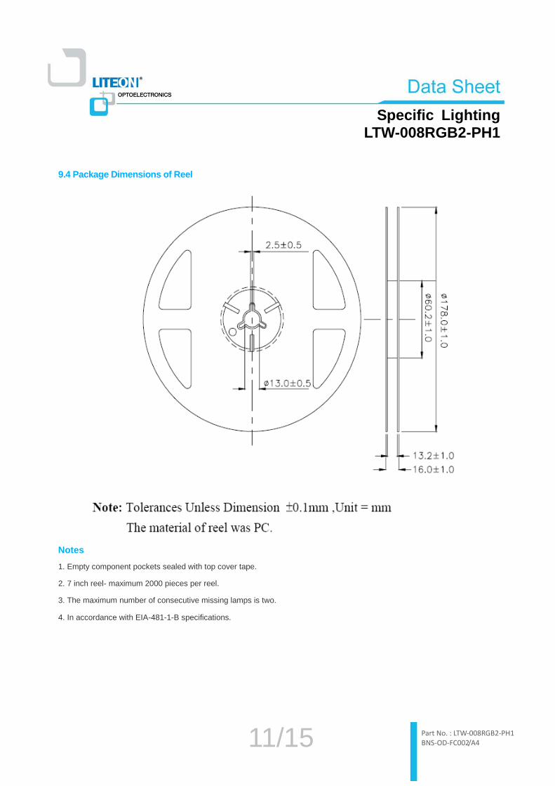
9.4 Package Dimensions of Reel
Notes
1. Empty component pockets sealed with top cover tape.
2. 7 inch reel- maximum 2000 pieces per reel.
3. The maximum number of consecutive missing lamps is two.
4. In accordance with EIA-481-1-B specifications.

12/15 Part No. : LTW-008RGB2-PH1 BNS-OD-FC002/A4
Specific Lighting
LTW-008RGB2-PH1
10. CAUTIONS
10.1 Application
The LEDs described here are intended to be used for ordinary electronic equipment (such as office equipment,
communication equipment and household applications).Consult Liteon’s Sales in advance for information on applications in
which exceptional reliability is required, particularly when the failure or malfunction of the LEDs may directly jeopardize l ife or
health (such as in aviation, transportation, traffic control equipment, medical and life support systems and safety devices).
10.2 Storage
This product is qualified as Moisture sensitive Level 3 per JEDEC J-STD-020 Precaution when handing this moisture sensitive
product is important to ensure the reliability of the product.
The package is sealed:
The LEDs should be stored at 30°C or less and 90%RH or less. And the LEDs are limited to use within one year, while the
LEDs is packed in moisture-proof package with the desiccants inside.
The package is opened:
The LEDs should be stored at 30°C or less and 60%RH or less. Moreover, the LEDs are limited to solder process within
168hrs. If the Humidity Indicator shows the pink color in 10% even higher or exceed the storage limiting time since opened,
that we recommended to baking LEDs at 60°C at least 48hrs. To seal the remainder LEDs return to package, it’s
recommended to be with workable desiccants in original package.
10.3 Cleaning
Use alcohol-based cleaning solvents such as isopropyl alcohol to clean the LED if necessary.
10.4 Soldering
Recommended soldering conditions:
Reflow soldering Soldering iron
Pre-heat
Pre-heat time
Soldering Temp.
Soldering time
120~150°C
120 sec. Max.
260°C Max.
30 sec. Max.
Temperature
Soldering time
300°C Max.
3 sec. Max.
(one time only)

13/15 Part No. : LTW-008RGB2-PH1 BNS-OD-FC002/A4
Specific Lighting
LTW-008RGB2-PH1
10.5 Drive Method
An LED is a current-operated device. In order to ensure intensity uniformity on multiple LEDs connected in parallel in an
application, it is recommended that a current limiting resistor be incorporated in the drive circuit, in series with each LED as
shown in Circuit A below.
Circuit model A Circuit model B
L E D
LED
(A) Recommended circuit.
(B) The brightness of each LED might appear different due to the differences in the I-V characteristics
of those LEDs.
10.6 ESD (Electrostatic Discharge)
Static Electricity or power surge will damage the LED.
Suggestions to prevent ESD damage:
Use of a conductive wrist band or anti-electrostatic glove when handling these LEDs.
All devices, equipment, and machinery must be properly grounded.
Work tables, storage racks, etc. should be properly grounded.
Use ion blower to neutralize the static charge which might have built up on surface of the LED’s plastic lens as a result of
friction between LEDs during storage and handling.
ESD-damaged LEDs will exhibit abnormal characteristics such as high reverse leakage current, low forward voltage, or “ no
light-up ” at low currents.
To verify for ESD damage, check for “ light-up ” and Vf of the suspect LEDs at low currents.
The Vf of “ good ” LEDs should be >[email protected] for InGaN product

14/15 Part No. : LTW-008RGB2-PH1 BNS-OD-FC002/A4
Specific Lighting
LTW-008RGB2-PH1
11. Suggested Checking List
Training and Certification
1. Everyone working in a static-safe area is ESD-certified?
2. Training records kept and re-certification dates monitored?
Static-Safe Workstation & Work Areas
1. Static-safe workstation or work-Sreas have ESD signs?
2. All surfaces and objects at all static-safe workstation and within 1 ft measure less than 100V?
3. All ionizer activated, positioned towards the units?
4. Each work surface mats grounding is good?
Personnel Grounding
1. Every person (including visitors) handling ESD sensitive (ESDS) items wear wrist strap, heel strap or conductive shoes
with conductive flooring?
2. If conductive footwear used, conductive flooring also present where operator stand or walk?
3. Garments, hairs or anything closer than 1 ft to ESD items measure less than 100V*?
4. Every wrist strap or heel strap/conductive shoes checked daily and result recorded for all DLs?
5. All wrist strap or heel strap checkers calibration up to date?
Note: *50V for Blue LED.
Device Handling
1. Every ESDS items identified by EIA-471 labels on item or packaging?
2. All ESDS items completely inside properly closed static-shielding containers when not at static-safe workstation?
3. No static charge generators (e.g. plastics) inside shielding containers with ESDS items?
4. All flexible conductive and dissipative package materials inspected before reuse or recycle?
Others
1. Audit result reported to entity ESD control coordinator?
2. Corrective action from previous audits completed?
3. Are audit records complete and on file?

15/15 Part No. : LTW-008RGB2-PH1 BNS-OD-FC002/A4
Specific Lighting
LTW-008RGB2-PH1
12. Revision Information
Version Page Content of Change Date Record
A 1 The package layout changed. 2010/05/05
B 3, 4
1. Red min. lumen spec modify from 1.61 to 1.70
2. White min. lumen spec modify form 6.32 to 6.41 (Based on
Red min lumen modify)
3. Green max. Vf spec modify from 3.6 to 3.55
2010/05/07
C 1, 6, 7 1. New design solder pin of lead frame modify.
2. Typical electrical / optical characteristics curves modify. 2010/07/13
D 3, 4, 5 Luminous flux and color spec modify. 2010/08/24
E 1, 3, 10
1. Add the dimensions of pick-up area.
2. Green max. Vf spec modify from 3.65 to 3.55
3. Duration time for RA test modify. (follow 2K10)
2010/10/22
F 6 Add shipping label code list 2010/12/08
G 4, 5, 6 Color spec modify 2011/01/24
H 3 Green max. Vf spec modify from 3.55 to 3.6 2012/05/08
I 4, 5, 6, 7, 8 1. Min. lumen spec modify
2. Color spec modify 2014/11/21
J 2 Modify solder pins description 2015/09/14