lu qianqian, tiainen jonna, kiani-oshtorjanimehran, wu
TRANSCRIPT

This is a version of a publication
in
Please cite the publication as follows:
DOI:
Copyright of the original publication:
This is a parallel published version of an original publication.This version can differ from the original published article.
published by
Lateral Force Acting on the Sliding Spool of Control Valve Due to Radial FlowForce and Static Pressure
Lu Qianqian, Tiainen Jonna, Kiani-Oshtorjani Mehran, Wu Yangfang
Lu, Q., Tiainen, J., Kiani-Oshtorjani, M., Wu, Y. (2021). Lateral Force Acting on the Sliding Spoolof Control Valve Due to Radial Flow Force and Static Pressure. IEEE Access, vol. 9. pp.126658-126669. DOI: 10.1109/ACCESS.2021.3112188
Author's accepted manuscript (AAM)
IEEE
IEEE Access
10.1109/ACCESS.2021.3112188
© IEEE 2021

Received August 30, 2021, accepted September 8, 2021, date of publication September 13, 2021,date of current version September 20, 2021.
Digital Object Identifier 10.1109/ACCESS.2021.3112188
Lateral Force Acting on the Sliding Spool ofControl Valve Due to Radial Flow Forceand Static PressureQIANQIAN LU 1, JONNA TIAINEN 2, MEHRAN KIANI-OSHTORJANI 2, AND YANGFANG WU11School of Engineering, Zhejiang University City College, Hangzhou, Zhejiang 310015, China2School of Energy Systems, LUT University, 53850 Lappeenranta, Finland
Corresponding author: Yangfang Wu ([email protected])
This work was supported by Zhejiang Provincial Natural Science Foundation under Grant LQ19E050018 and Grant LGG20E050007. Thework of Mehran Kiani-Oshtorjani was supported by the SIM-Platform at LUT University.
ABSTRACT The hydraulic sliding-spool valve is a key component to control the flow rates and thuspressures in different hydraulic volumes. The lateral force on the spool is one of the important effectsresulting from moving resistance. This paper presents research aimed at understanding the effects of radialflow force and static pressure upon the lateral force. The radial flow force is calculated from three typesof control surfaces labelled with square land, 45◦ conical, and round curved surfaces, for discovering theeffects of control profile, combined with inlet and outlet control conditions. The pressure difference effectis analyzed along with six cases under the same orifice opening, and the radial flow force is found to varylinearly with the pressure difference. The results also indicate that the radial force for the inlet control modeis less than that of the outlet control mode. The jet angle is discovered to not only be related to the annularorifice opening and gap clearance, but is also influenced by the flow direction and control surface profile.The static pressure is the predominant factor in the lateral force compared to the radial flow force. The resultsindicate that the static pressure variation on the surface of the cylindrical spool shoulder increased linearlywith the inlet pressure; and two stagnation points can be observed in the case of the valve cavity with oilpassages on the same section, and square land control edge profile. The lateral force on the spool increaseswith the pressure, and could reach to the maximum of 300 N, implying that this force should be taken intoaccount in the selection of an actuator, especially in high pressure applications.
INDEX TERMS Flow force, jet angle, lateral force, sliding-spool valve, static pressure.
I. INTRODUCTIONFlow force is often considered as one of the critical fac-tors affecting the performance of a hydraulic control unit.A hydraulic spool valve with a spool sliding along its axial,is used to control flow direction, or flux by manipulatingspool position or displacement. When the annular orificeformed by the spool land and housing is opened by a smallsize, the liquid flows through the orifice causing the flowvelocity to change. Therefore, there is a flow force acting onthe spool because of the time variation in fluid momentum.
The flow forces are usually divided into steady-state andtransient flow forces. However, the transient flow force asoften been ignored because it was smaller than the steady flowforce and the pressure force [1], [2]. Many researchers have
The associate editor coordinating the review of this manuscript and
approving it for publication was Agustin Leobardo Herrera-May .
focused on the axial steady-state flow force because it is oneof the axial components that the actuator should overcome.The expressions of steady-state and transient flow forces canbe used to obtain the equation of motion of the valve spool.This equation of motion has been used to calculate the axialflow forces acting on the spool of the directional controlvalves, and compensates for the flow forces [3]. The impor-tance of reducing the flow forces has been illustrated [4] whenthe flow forces are acting on the valve piston of the hydraulicsliding-spool valve, under high flow rate and pressure con-ditions. The compensation method has been presented [4]for inlet control edge, by modifying the sliding spool witha conical form on the inlet control edge. While for the outletcontrol edge, it has been demonstrated by designing a conicalsurface on the inner side of the valve socket at the outlet port,to conduct the outlet oil jet back to the slide spool. The spoolprofile of a hydraulic directional valve for compensation was
126658 This work is licensed under a Creative Commons Attribution 4.0 License. For more information, see https://creativecommons.org/licenses/by/4.0/ VOLUME 9, 2021

Q. Lu et al.: Lateral Force Acting on Sliding Spool of Control Valve Due to Radial Flow Force and Static Pressure
also studied [5], and a corrected equation to calculate flowforce while considering the static pressure distribution in thevalve cavity and pressure loss in nozzles was created [6].The flow forces between the traditional square land spool,and the turbine-bucket spool, were compared by conductingexperiments [6]. The results indicated that the flow forcewas influenced by the attachment of the jet to the spool, andthe beveled spool compensated for the flow force, becauseof the high and unbalanced pressure acting on the upstreamfrom the valve’s orifice [7]. Other compensation methodswere created by increasing the structure damping. The spoolstructure for instance, was optimized by adding a damping tailto compensate for the flow force acting on the spool, withoutaffecting the pressure drop between the inlet and the outletpassages [8]. In similar work [9], a damping flange on thespool of the same cartridge valve was designed to decreasethe axial flow force by 93 percent in the experimental test.In addition, flow force could be reduced by modifying thenon-metering port geometry which improved the agility ofthe single stage electrohydraulic valves [10].
Besides the optimization of the spool structure by useof the compensation method, the axial flow force of aone-directional valve was also simulated [11], [12], and it wasfound that the flow velocity values were influenced by thespool displacement. The flow force was also found to bemoreinfluenced by the valve opening, than by the temperature ofthe flow servo valve used for the fuel metering unit [13].
The above-mentioned studies focused on the axial compo-nent of the steady-flow force, because it acts in the oppositedirection to the drive force, and should be overcome duringthe work process. Thus, researchers have been trying to min-imize the axial force in order to improve the power-to-weightratio of the hydraulic control unit.
However, there exist frictional and inertial forces which areeffective against the drive forces [2], [4] except for the flowforce in a hydraulic spool valve. The reduction of the inertialforce can only be achieved through a reduction in the mass ofthe moving components. The friction forces however, consistof the Coulomb friction produced by the viscosity friction andradial forces. The former exists when the spool is located inthe exact centre of the bore, with constant radial clearanceover the entire periphery. The latter appears when the spool isaxially aligned but with eccentricity, tilt, as well as the profilemachining error, such as the taper of the spool land. The taperspool contributes to the increase of the radial forces when thepressure at the larger end of the shoulder is higher than at thesmaller end [3]. In addition, the contaminated friction of theclearance fit between the spool and its bore was also studiedthrough the experiments [14]. The contaminated friction wasincreased on the cis-conical spool, but was decreased onthe invert cone spool [14]. The contamination friction canbe prevented by using a fine filter and by improving themachining accuracy.
The frictional forces can prevent the spool from moving,this phenomenon is called a hydraulic lock. The spool strokemechanism of a pressure servo valve was investigated by
considering the static-sliding friction, gap flow theory, andthe flow force when the spool had the tendency to tilt axi-ally [15]. The experimental test results of static friction forcesacting on the spool of a hydraulic directional control valveloaded with axial and flow forces have been presented [16].The results indicated that the frictional forces depend on theaxial forces acting on the spool [16].
The forces derived from the liquid stream acting on thevalve spool of directional control valve were computed [17],and the results indicated that the flow forces acting perpen-dicular to the spool axially were 40 N, and 28 N at the inletpassage in the directions along the port and normal to theport axes, respectively. The forces were 252 N, and 83 N forthe outlet passage, when the flow rate was 450 l/min. Theseresults demonstrated that flow forces acting perpendicular tospool axis should not be neglected, especially when calculat-ing the driving force of the valve, as the force acting radiallyresults in increasing friction. However, a detailed analysiswas not provided [17].
So far, many researchers [4]–[7] have assumed that theradial flow force cancels itself out because of the assumptionthat the structure is symmetrical, and hence the radial flowforce balance being zero. Actually, the three dimensionalflow cavity inside the valve is not completely symmetrical,because the hydraulic valve should be arranged according toeither the pipe systems, or valve block. Most of the hydraulicdirectional control valves are subplate-mounted so that thelocation of the oil ports are machined on the installationsurface according to the ISO standards [18], resulting inunbalanced pressure, and velocity distributions around thecylindrical surfaces of the spool, as well as the annular ori-fices formed by the spool and sleeve (housing). The unbal-anced radial component will force the spool against the bore,and the Coulomb friction forces may cause the spool tostroke.
Numerical simulation can provide important informationabout the jet angle values and the flow rate distributioninside the valve, in order to assist in obtaining precise flowforce. The flow forces acting on the spool of an open-centerhydraulic directional control valve were studied throughexperiments, CFD simulation, and theoretical analysis [19].It was found that the maximum value of flow force appearedwhen the recirculating flow vanished, and the peak value offlow force occurred at the same opening around 2.4 mm,and the value increased along with the increasing pump flowrate [20]. The importance of using full 3D fluid dynamicsanalysis was emphasized [21], to more accurately evaluatethe flow forces in a hydraulic directional proportional valvethan it would in 2D and simplified 3D models. The structureof the sliding spool was modified to reduce the actuationforces [22].
The radial flow force at the annular orifice acting on thesliding spool with a conical side surface of a two-dimensionalvalve was studied numerically [23]. The results [23] demon-strated that the radial flow force increases with both thedecreasing valve opening and increasing inlet flow velocity,
VOLUME 9, 2021 126659
Q. Lu et al.: Lateral Force Acting on Sliding Spool of Control Valve Due to Radial Flow Force and Static Pressure
and the net flow force should be considered when calculatingresistant forces. However, the study [23] did not consider theeffects of control edge profiles, flow directions, or oil passagelocations on the radial flow force.
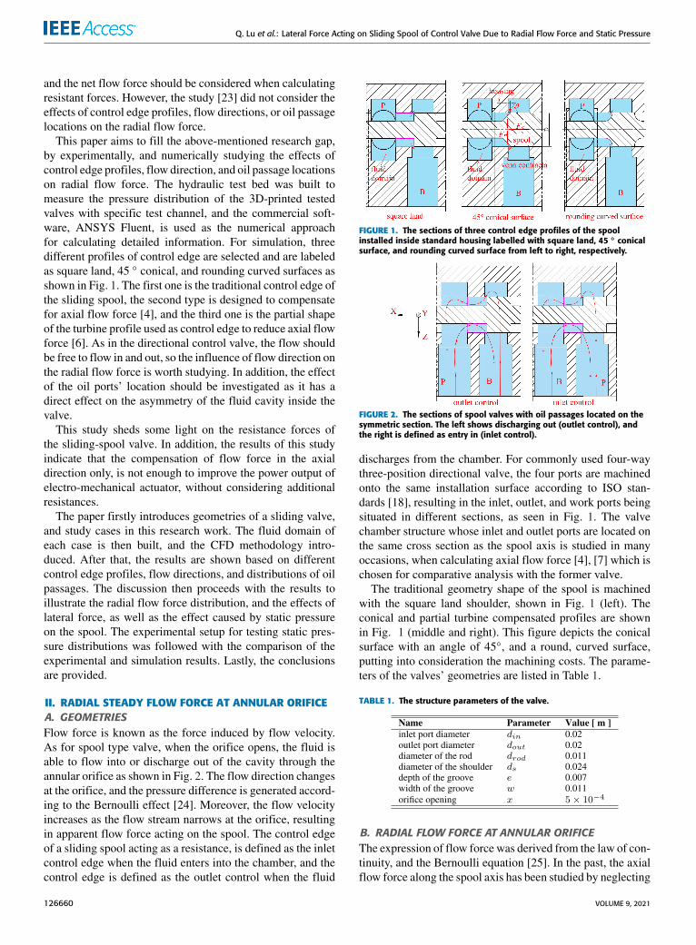
This paper aims to fill the above-mentioned research gap,by experimentally, and numerically studying the effects ofcontrol edge profiles, flow direction, and oil passage locationson radial flow force. The hydraulic test bed was built tomeasure the pressure distribution of the 3D-printed testedvalves with specific test channel, and the commercial soft-ware, ANSYS Fluent, is used as the numerical approachfor calculating detailed information. For simulation, threedifferent profiles of control edge are selected and are labeledas square land, 45 ◦ conical, and rounding curved surfaces asshown in Fig. 1. The first one is the traditional control edge ofthe sliding spool, the second type is designed to compensatefor axial flow force [4], and the third one is the partial shapeof the turbine profile used as control edge to reduce axial flowforce [6]. As in the directional control valve, the flow shouldbe free to flow in and out, so the influence of flow direction onthe radial flow force is worth studying. In addition, the effectof the oil ports’ location should be investigated as it has adirect effect on the asymmetry of the fluid cavity inside thevalve.
This study sheds some light on the resistance forces ofthe sliding-spool valve. In addition, the results of this studyindicate that the compensation of flow force in the axialdirection only, is not enough to improve the power output ofelectro-mechanical actuator, without considering additionalresistances.
The paper firstly introduces geometries of a sliding valve,and study cases in this research work. The fluid domain ofeach case is then built, and the CFD methodology intro-duced. After that, the results are shown based on differentcontrol edge profiles, flow directions, and distributions of oilpassages. The discussion then proceeds with the results toillustrate the radial flow force distribution, and the effects oflateral force, as well as the effect caused by static pressureon the spool. The experimental setup for testing static pres-sure distributions was followed with the comparison of theexperimental and simulation results. Lastly, the conclusionsare provided.
II. RADIAL STEADY FLOW FORCE AT ANNULAR ORIFICEA. GEOMETRIESFlow force is known as the force induced by flow velocity.As for spool type valve, when the orifice opens, the fluid isable to flow into or discharge out of the cavity through theannular orifice as shown in Fig. 2. The flow direction changesat the orifice, and the pressure difference is generated accord-ing to the Bernoulli effect [24]. Moreover, the flow velocityincreases as the flow stream narrows at the orifice, resultingin apparent flow force acting on the spool. The control edgeof a sliding spool acting as a resistance, is defined as the inletcontrol edge when the fluid enters into the chamber, and thecontrol edge is defined as the outlet control when the fluid
FIGURE 1. The sections of three control edge profiles of the spoolinstalled inside standard housing labelled with square land, 45 ◦ conicalsurface, and rounding curved surface from left to right, respectively.
FIGURE 2. The sections of spool valves with oil passages located on thesymmetric section. The left shows discharging out (outlet control), andthe right is defined as entry in (inlet control).
discharges from the chamber. For commonly used four-waythree-position directional valve, the four ports are machinedonto the same installation surface according to ISO stan-dards [18], resulting in the inlet, outlet, and work ports beingsituated in different sections, as seen in Fig. 1. The valvechamber structure whose inlet and outlet ports are located onthe same cross section as the spool axis is studied in manyoccasions, when calculating axial flow force [4], [7] which ischosen for comparative analysis with the former valve.
The traditional geometry shape of the spool is machinedwith the square land shoulder, shown in Fig. 1 (left). Theconical and partial turbine compensated profiles are shownin Fig. 1 (middle and right). This figure depicts the conicalsurface with an angle of 45◦, and a round, curved surface,putting into consideration the machining costs. The parame-ters of the valves’ geometries are listed in Table 1.
TABLE 1. The structure parameters of the valve.
B. RADIAL FLOW FORCE AT ANNULAR ORIFICEThe expression of flow force was derived from the law of con-tinuity, and the Bernoulli equation [25]. In the past, the axialflow force along the spool axis has been studied by neglecting
126660 VOLUME 9, 2021

Q. Lu et al.: Lateral Force Acting on Sliding Spool of Control Valve Due to Radial Flow Force and Static Pressure
FIGURE 3. Computational domain and grid.(a) the asymmetric controlvolume, (b) the symmetric control volume. Control surface: I - squareland, II - rounding control, III - 45◦ conical control.
the radial component. However, the existence of radial flowforce should be considered. It could be compensated for tosome extent, even though not in full as proven by Rajda andLisowski [17]. The radial flow force could be expressed asEq.(1) with the direction perpendicular to the spool axis.
Fr = 2CqCvπdsx1psinθ (1)
where, Fr is the radial flow force, in newtons (N); Cq isthe flow coefficient, Cv is the velocity coefficient, 1p isthe pressure difference in pascals (Pa), which is calculatedby subtracting outlet pressure from inlet pressure for thecontrol volume, and θ is the jet angle referring to the acuteangle between the velocity at the vena contracta, and the Xdirection, shown in Fig. 2.
Here, the radial flow distribution along the annular orificeis considered by assuming that the spool axis is co-axial tothe bore, which means that the effect of the radial force isdirectly related to the pressure difference, and the jet angleaccording to Eq.(1). Besides these two effects, the locationof the oil ports contributes to the pressure distribution at theorifice, which should be considered [23]. The flow directionreferred to as entry in, or discharge out from the cavity alsohas an influence over the flow force according to [4].
III. NUMERICAL MODELINGA. COMPUTATIONAL DOMAIN AND MODELINGThe parameters, shown in Table 1, were used to build thefinite-element model of the valve fluid domain. The 3D fluidasymmetric control volume was chosen to analyze the radialflow force at the annular orifice of the sliding valve. Thecomputational domain is shown in Fig. 3(a), (b), which rep-resents the Fig. 1 (left) and the rounding curved surface forsymmetric volume, respectively. The grid near the annularorifice where the maximum velocity, and pressure gradientsare, is refined as shown I, II, III in Fig. 3. Other cases withdifferent control edges or structures were processed in thesame way.
In the whole computational domain, the pressure inletand pressure outlet are chosen as inlet and outlet boundary
conditions. The rest of the surfaces were defined as walls withno-slip condition. The fluid is the 46# anti-wear hydraulicoil with the density of 899 kg/m3, and a kinematic viscosityof 46 mm2/s. Two flow directions (from P to B and viceversa) are analyzed by inverting the inlet and outlet pres-sure boundary conditions. The convergence criteria was setto the residual values of continuity, x-velocity, y-velocity,z-velocity, and k and epsilon were less than 10−5. Meanwhile,the mass flow rate difference between inlet and outlet wasset less than 10−5 as one requisite convergence criteria toguarantee the conservation of mass.
RNG k − ε model was used to predict the turbulence.In this study, the lowest Reynolds number is 346 at the annularorifice for all simulation conditions. This is higher than thecritical Reynolds number, which ranges from 250 to 275 ofthe slide valve [26]. The RNG k − ε model is the mostsuitable turbulence model for determining the valve flowfeatures, as the flow inside a hydraulic valve is characterizedby the coexistence of ‘‘free shear flows’’ due to the flow jetat the exit of the metering section [20]. The Enhanced WallTreatment (EWT) is used as the near-wall treatment, as EWTprovides consistent solutions for all y+ values, especiallywhen using the k − ε model for general single-phase fluidflow problems [27].
The governing equations were solved using the pressure-based solver. The SIMPLE scheme was selected for pressure-velocity coupling, and pressure discretization was producedby PRESTO!. The second-order upwind scheme was used todiscretize the momentum, turbulent kinetic energy, and theturbulent dissipation equations.
Simulations were conducted for four different inlet pres-sures of 5, 10, 15, and 25 MPa, three types of control edges,two flow directions, and standard ports distribution (asym-metric) versus symmetric distribution. For slide valves withplated installation, the fluid flows from cylindrical inlet pas-sage, as the internal flow and the inlet flow were fully devel-oped, intensity and hydraulic diameter were chosen as theturbulence specification method. The hydraulic diameter wasset to 20 mm equal to the diameter of the inlet port of themodel, and the turbulent intensity was set to 8%. The value ofturbulent intensity was estimated via the empirical correlation
I ≡ u′/uavg = 0.16(ReDH )−1/8 (2)
where, I is the turbulence intensity which is defined as theratio of the root-mean-square of the velocity fluctuations u′,to the mean flow velocity uavg, and ReDH is the Reynoldsnumber [27].
B. GRID INDEPENDENCE ANALYSISFour different unstructured meshes with 0.37, 0.99, 2.5, and5.7 million computational cells were created with the com-mercial software ANSYS Meshing, to investigate the meshindependence. These meshes are labeled with Grid 1 toGrid 4 in Fig. 4. The mesh independence simulations areconducted for a valve opening of 0.5 mm with outlet pres-sure being 0.1 MPa. The discretization error was estimated
VOLUME 9, 2021 126661

Q. Lu et al.: Lateral Force Acting on Sliding Spool of Control Valve Due to Radial Flow Force and Static Pressure
FIGURE 4. The mass flow rate comparison for grid independence analysis(x = 0.5 mm, inlet pressure is set to 10 MPa and outlet pressure is set to0.1 MPa).
using the procedure presented by Celik et al. [28]. The massflow rate was chosen as the studied variable. The error barsin Fig. 4 present the discretization error compared to thefinest grid (Grid 4). The relative error of mass flow rate ofGrid 3 is 0.08% compared to the Grid 4, and 1.2% and 2.5%for Grid 2 and Grid 1, respectively. Therefore, Grid 3 wasselected for the rest of fluid domains with the same opening.
IV. RESULTS AND ANALYSISA. THE CONTROL VOLUMEThe radial flow force here represents the flow force pro-jecting perpendicular to the spool axis, which influencesthe lateral force. As flow velocity changes dramatically atthe orifice, the pressure difference before and after orificemainly determines the radial flow force according to Eq. (1).In order to calculate the force value, the annulus fluid domainselected as the control volume shown in Fig. 5, was cutfrom whole computational fluid domain, which is displayedin dashed-line rectangles in Fig. 1, and Fig. 2. The controlvolume chosen here has an advantage in that, the effectsof the inner structure and oil passages location of the valvehave been considered. This is more reliable than simulationresults that held the assumption, that the fluid domain wascompletely symmetrical with the annulus being chosen as theonly computational domain.
Fig. 5(a) shows the annulus fluid domain selected for forcecalculation in the outlet control mode. The red annular surfaceshown on the left side of the volume, is the pressure inlet; andthe annular orifice opening, colored in green, is the pressureoutlet. The inner and outer walls are part of the spool andhousing surfaces, respectively. Fig. 5(b)–(d) represents oneof twelfth areas of the control volumes for square land, 45◦
conical, and rounding curved control surfaces. It is obviousthat the definition of the inlet and outlet boundaries should beexchanged in the inlet control condition. The pressure infor-mation was collected from the annulus fluid domain from the
FIGURE 5. Annular fluid domain cut from whole computational domainused as control volume for calculating radial flow force. (a) annular flowdomain, (b) one-twelfth fluid domain of square land, (c)one-twelfth fluiddomain of 45◦ conical surface, (d) one-twelfth fluid domain of roundingcurved surface.
numerical results of both the inlet and outlet surfaces. In orderto gather the flow force distribution around the orifice, sixsections through the spool axis were created, whose locationswere separated by an interval angle of 30 ◦ as shown on Fig. 6.
FIGURE 6. Six sections’ positions of annular fluid domain through spoolaxis.
The pressure distributions on the twelve inlet and outletlines are shown in Fig. 7, where the X -coordinate is the radialdistance from the inner wall to the outer wall, and Fig. 8where the X -coordinate is the distance of the orifice openingfrom the static housing control edge to the spool control edgeunder outlet control condition with rectangular edge, whenthe inlet pressure is 25 MPa and outlet pressure is 0.1 MPa.It is obvious that the pressure distributions at twelve inlet linesvary with the line position, while the pressure at twelve outletlines at the annular orifice shows similar trends, but the valuespresent differently.
The velocity at the orifice has a direct contribution to thefluid momentum, and is also used to determine the flow typeas the definition of the Reynolds number. The twelve velocitydistributions at the orifice along outlet lines under the samecondition of Fig. 8 are shown in Fig. 9, this demonstratesthat the flow is turbulent as the velocity values on the outletline are close except at the two ends. Even though the velocityat the orifice was easy to acquire, the radial flow force in this
126662 VOLUME 9, 2021

Q. Lu et al.: Lateral Force Acting on Sliding Spool of Control Valve Due to Radial Flow Force and Static Pressure
FIGURE 7. Pressure distributions along the inlet edge.
FIGURE 8. Pressure distributions at the orifice along the spool axis fromhousing edge to spool control edge.
work was calculated by using the pressure difference and notthe velocity, as the velocity directions at inlet lines are notalways parallel to the spool axis, and are hard to determine.In formula 1, the parameter jet angle was deduced by usingoverall velocity v, and the velocity u vx which projects in theX direction as the Eq.3, 1P is deduced by using the averagepressure on the inlet edge minus the value on the outlet edgeat the same position in Fig.5(b). Fig. 10 shows radial flowforce variations along the orifice periphery under three typesof control profiles, four different inlet pressures, metering-inand metering-out cases for the symmetric valve.
θ = acosvxv
(3)
B. RADIAL FLOW FORCEFig. 10(a) - (f) denotes the absolute radial flow force onthe spool increases with inlet pressure, which also representspressure difference; the outlet boundary here was set to anatmosphere that was suitable to the condition when the outlet
FIGURE 9. Velocity distributions at the orifice along the spool axis fromhousing edge to spool control edge.
port is directly connected to the tank. The mean radial flowforce has a linear relationship as analyzed by authors in[23]. In the outlet control conditions, the radial flow force issmallest at the 45◦ conical control edge among three controlprofiles. On the contrary, the force on the spool with conicalprofile is highest among the three inlet control profiles.
Figure 11 shows the radial flow force variation along theperiphery of the annular orifices under three control profilesof sliding spool, inlet, and outlet control cases when the inletpressure was set to four different pressures. This indicates thatthe radial flow forces are much higher when fluid dischargesout of the cavity, than when the fluid discharges out underthe circumstances of the rectangular and round control edges.The radial flow force differences between inlet and outletcontrol modes under the 45 ◦ conical profile, are closer thanthe force differences of the other two profile types.
C. NET RADIAL FLOW FORCEAs flow force has a direct connection with the velocity,and the direction of the force is determined by the direc-tion of the velocity at the orifice, this results in the orificeopening closing [7], and thus the direction of radial flowforces on the spool is bound to point towards the spool axisand circumferential distribution. The force therefore, couldself-compensate partially, but this will result in net radialflow force which should not be ignored as explained byLu et al. [23]. The net radial flow force of each case wascalculated by projecting the force at each position to the Y andZ directions, and summed up to achieve root-mean-squarevalue according to formula 6. The values of net radial flowforces of all the simulation results are presented in Fig. 12.
FrY = −∑
Fr (α)sinα (4)
FrZ = −∑
Fr (α)cosα (5)
VOLUME 9, 2021 126663

Q. Lu et al.: Lateral Force Acting on Sliding Spool of Control Valve Due to Radial Flow Force and Static Pressure
FIGURE 10. Radial flow force distributions along orifice periphery of threeprofiles under different pressures and flow directions. ( a ) the squareoutlet control surface, ( b ) the square inlet control surface, ( c ) the 45◦conical outlet control, ( d ) the 45◦ conical inlet control surface, ( e ) therounding outlet control surface, ( f ) the rounding inlet control surface.
where FrY is the Y component of the net radial flow force,and FrZ is the Z component. Net radial flow force Frn actingon the spool at the orifice is the square root of the FrY andFrZ values, according to the formula (6):
Frn =√F2rY + F
2rZ (6)
Fig. 12 demonstrates that the net radial flow force increaseswith the inlet pressure. The maximum net radial flow force isless than 4 N when the opening is 0.5 mm. And the forceof asymmetric structures is less than 4 N under the samecondition of symmetric structures, when the fluid flows outof the cavity. While the force in asymmetric structures ishigher than that of symmetric structures, when the controledge profiles are rectangular and round, but the value of theconical profile shows the opposite.
D. EFFECT OF THE PRESSURE DIFFERENCEThe pressure difference has a linear relationship with theradial flow force as shown in the formula 1. Fig. 13 shows the
FIGURE 11. Radial flow force variations of three profiles, inlet and outletcontrol modes, and four pressures when the oil ports are asymmetric.(a) 5 MPa, (b) 10 MPa, (c) 15MPa, (d) 25 MPa.
average radial flow force from the values of twelve positionchanges with inlet pressure, when outlet pressure is set toatmospheric pressure. The straight lines of different simu-lation conditions present the linearity which goes well withthe formula 1, and shows that the average radial flow forceincreases with the pressure difference. However, the slope ofthe lines in Fig. 13 varies with control surface profiles andflow directions, whereas straight lines are quite close underthe same conditions except the symmetry of the cavity. Thelargest slope appears at the outlet control with rectangularand round control edges when the cavity is plane symmetry,while the slope is the least steep at the inlet control withthe rectangular control edge. From formula 1, it expressesthat the slope of the lines in Fig. 13 has a direct relation to2CqCvπx sin θ . However, the pressure difference extractedfrom the calculation of flow domain acts as a vital effect. Onereason is that the jet angle θ is not always constant as shownin Fig.14, which is a critical factor on the slope in Fig.13.
In addition to the average radial flow force, the net radialflow force increases with the pressure difference demonstrat-ing linearity in Fig. 12.
E. EFFECT OF THE CONTROL SURFACE PROFILEThe radial flow forces show not only different values, butalso different trends in the three profiles on the spool usedfor control surface. The force values of the square and roundprofiles under the outlet control case present a similar trend asshown in Figs. 10,11, and 12. The largest percentage error ofaverage radial flow force between square and round profilesis 0.83 percent for the symmetric conical, and 0.82 percent forthe asymmetric conical. However, for the inlet control case,the radial flow force at square control edge is lower than the
126664 VOLUME 9, 2021

Q. Lu et al.: Lateral Force Acting on Sliding Spool of Control Valve Due to Radial Flow Force and Static Pressure
FIGURE 12. Net radial flow force of three types of control edges underdifferent pressures and flow directions. (a)-(b) the rectangular controledge, (c)-(d) the conical control edge, (e)-(f) the round control edge.
value at the round profile. The radial flow forces under thecondition of conical control edge present differently with theother two profiles, which shows that the force value is higherthan the other two inlet control cases, while smaller for outletcontrol edge.
For the square control profile, the radial flow force at theannular orifice of the inlet controlmode, ismuch less than thatof the value of outlet control for both symmetrical and asym-metrical valve structures. Fig. 13 shows the average radialflow force is 0.56 N for inlet control, and 7.45 N for outletcontrol for the symmetric structure when the inlet pressureis set to 5 MPa, and for the round control edge, the averageflow force is 1.00 N and 7.51 N under the same condition.However, for the conical control edge, the average flow forcefor inlet control is 3.86 N, and 5.30 N for outlet control at5 MPa inlet pressure with symmetric structure. Moreover,the value differences also increases with the pressure.
F. EFFECT OF CAVITY SYMMETRYThe symmetric cavity of the sliding spool valve here has thefeature that the inlet and outlet passages are machined on the
FIGURE 13. The straight lines of average radial flow force with respect topressure difference.
same section, and the other structure inwhich the passages arelocated on the respective sections according to ISO standard,is labeled with asymmetric valve. The average radial flowforce which increases with pressure for the symmetric valvehas similar tendencies to the asymmetric valve as shownin Fig. 13. The largest relative error for the square outletcontrol profile between the symmetric and asymmetric valvesis 8.3 percent by using the average flow force when theinlet pressure is 25 MPa, the relative error decreases withthe pressure. Thus the symmetry of the valve has little effecton the radial flow force. However, the net radial flow forcewhich contributes to one actual lateral force caused by radialflow force is influenced by valve symmetry. The net radialflow force of the asymmetric valve is less than the value ofthe symmetric valve for each result shown in Fig. 12. Thevalue of the square outlet control mode particularly, is atits minimum at 25 MPa, while the minimum value of theinlet control occurs at 25 MPa on the conical profile spool.There are two stagnation points on the symmetric plane forthe symmetric valve [29], which in turn affects the pressuredistribution around the spool, shown in Fig.20. This results ina larger pressure difference than the value of the asymmetricvalve in which the stream flows around the spool surface in ahelical manner without a typical stagnation point [17].
G. EFFECT OF FLUID FLOW DIRECTIONThe directional valve was designed with the ability to freelyflow in two directions, the outlet control indicates when fluiddischarges out, while the inlet control means that the fluidenters into the cavity. It is visible that the flow directionhas a significant effect on the radial flow force as shownin Fig. 10, Fig. 11, and Fig. 13. The radial flow force ofinlet control is much less than the value of the outlet controlfor the three types of control profiles, and the four differentpressures. In Fig. 13, the average value of radial flow force
VOLUME 9, 2021 126665

Q. Lu et al.: Lateral Force Acting on Sliding Spool of Control Valve Due to Radial Flow Force and Static Pressure
of outlet square control profile is 17.9 times the value of theinlet control case at 25 MPa, and 9.3 and 1.25 times the inletcontrol value, when the control surface is round and conical,respectively. The net radial flow force for the inlet control isless than the value for the outlet control edge in most cases,except for the conical control surface with symmetric volume,when pressure is less than 25 MPa.
The net radial flow force difference of the conical profile,which is the absolute value between inlet and outlet controlcases at the same pressure, shows closest compared to theother two control profiles. The values are shown in Table 2 ofthree profileswhen the pressure varies from 5MPa to 25MPa.It illustrates that the lesser the difference in the radial flowforce, the closer the net radial flow force is.
TABLE 2. The net radial flow force differences.
H. EFFECT OF JET ANGLEThe jet angle is a necessary part of determining the steadyflow force, as it determines the direction of the flow velocity[26]. When the shoulder of the sliding spool was square land,the perimeter of the shoulder (75.4 mm) was larger comparedto the opening of the orifice (0.5 mm). The flow was thusconsidered to be two-dimensional and the Laplace equationcan be solved to determine the jet angle, which is presentedin formula (7)
xcr=
1+ π2 sin(θ)− ln(tan[π−θ2 ]cos(θ ))
1+ π2 cos(θ)+ ln(tan[π/2−θ2 ]sin(θ ))
(7)
where the cr , is the radial clearance between the valve andthe valve housing (sleeve). From this equation, the jet anglevaries between 21 to 69 degrees and for most valve openings,an angle of 69 degrees has been used as a good estimation forjet angle [26].
Jet angle is defined as the acute angle of the velocityvector at the orifice relative to the axial of the spool, and theangle is calculated according to equation (3). The average jetangle at the orifice for the round and square control surfaceis between 65 degrees and 68 degrees when the pressuredifference increases from 5MPa to 25MPa. The angle valuesof the asymmetric and symmetric cavities are quite close forthe square and round control profiles, shown in Fig. 14. How-ever, the jet angle of the conical profile performs differently,the average value of which is around 56 degrees for inlet con-trol, and 35 degrees for outlet control. In addition, the valuedecreases with the increasing of pressure for metering outwhich is opposite in the other cases.
It is indicated that the jet angle is not only influenced bythe opening and the clearance for the spool valve, but also thepressure difference, and the control profile, which meant thatformula 7 needed to be modified.
FIGURE 14. The relation between average jet angle and pressuredifference.
I. EFFECT OF STATIC PRESSURE ON THE SPOOLThe radial force on the spool surface plays a vital role in thevalve design, as it increases the frictional resistance. The netradial force 6Fr , which is also called the net lateral force,acting on the inner surface (spool surface), was directly calcu-lated according to the simulation results presented in Fig. 12,by using root square value of forces in the Y direction, andZ direction, shown in Fig. 15. The net lateral force not onlyincreases with increasing pressure, but is also a dozen timesthe net radial flow force at the annular orifice as shownin Fig. 13. It is obviously that the net lateral force varies fromover 100 N to 300 N at 25 MPa. And the net lateral forcesunder conical profiles show less than the value under othertwo control surfaces’ conditions in Fig. 15.
In order to figure out how the static pressure on the spoolsurface act on the lateral force. Pressure data are extractedfrom the two circles which are located on the spool surfaceat the inlet and outlet cross sections perpendicular to the axisshowing in Fig. 17, the pressure variations along the circle areplotted in Fig. 16. Curves in Fig. 16 shows the static pressureon the spool is not uniformly circumferential, resulting in alateral force on the spool.
Themax static pressure differences shown in Fig. 16(a), (b)are calculated according to formula 8, by using the maximumstatic pressure psmax minus theminimum static pressure psmin.The values are 0.095 MPa, 0.180 MPa, 0.225 MPa, and0.045 MPa when the inlet pressures are 5 MPa, 10 MPa,15MPa, and 25MPa, respectively.Meanwhile, Fig. 16(c), (d)show that the pressure differences at the outlet section onthe valve surface are 0.231 MPa, 0.547 MPa, 0.896 MPa,and 1.437 MPa, respectively under four inlet pressures from5 MPa to 25 MPa. The max static pressure difference showslinearity with inlet pressure as shown in Fig. 18. In addition,the ratio rps variation with static pressure difference 1psversus inlet pressure pin as formula 9, is plotted in Fig. 18,
126666 VOLUME 9, 2021

Q. Lu et al.: Lateral Force Acting on Sliding Spool of Control Valve Due to Radial Flow Force and Static Pressure
FIGURE 15. The relation between lateral force and pressure difference.
FIGURE 16. The static pressure variation on the spool surface at circlelines of the inlet and outlet sections when the control edge is rectangularat metering-out and symmetric condition. (a),(b) normalized pressurep/pin variation along Y and Z directions on the inlet line of the spool;(c),(d) pressure variation along Y and Z directions on the outlet line ofthe spool.
which confirms that the maximum static pressure differenceon the spool has a linear relation with inlet pressure whenoutlet pressure is directly connected to the tank.
1ps = psmax − psmin (8)
rps = 1ps/pin (9)
The pressure distribution on the inlet and outlet circleshown in Fig. 16 present symmetrically about plane Y = 0.If we assumed that the pressure distribution along the axisremains unchanged except at orifice area, the lateral forcegenerated by static pressure could be estimated by usingvalues in Fig. 16, and the surface area of the spool. The lateralforce caused by static pressure was calculated, and shownin Fig. 15 under outlet control condition when the valveis symmetric. This verifies that the uneven static pressure
FIGURE 17. The position of inlet and outlet circles on the spool foracquiring static pressure.
FIGURE 18. The variation of static pressure difference and ratio of staticpressure on inlet and outlet circles with inlet pressure.
distribution on the spool surface, plays a critical role incausing lateral force on the sliding spool.
V. EXPERIMENTAL SETUPTo verify the computational simulation results of the staticpressure distribution on the spool surface, the experimen-tal test bed, whose hydraulic schematic diagram is shownin Fig. 19(a), was established with a prototype seat valvecontaining a special test channel made of nylon using athree-dimensional printer, as shown in Fig. 19(b). Becauseof the limited size of the prototype, seven valves were printedto cover seven circumferential test positions θ (180◦, 210◦,240◦, 270◦, 300◦, 330◦, 360◦ (0◦)), on the section throughthe outlet port axis, perpendicular to the spool axis.
All seven tested valves were printed with the same modelsize shown in Fig. 2, the orifice opening was 0.5 mm.The installation platform with a 3D-printed valve is shownin Fig. 19(c). In order to arrange the pressure sensor on thetest rig, a transition valve block was fabricated, so as toconnect the valve, and the pressure sensors. The features of
VOLUME 9, 2021 126667

Q. Lu et al.: Lateral Force Acting on Sliding Spool of Control Valve Due to Radial Flow Force and Static Pressure
FIGURE 19. Hydraulic test bed. (a) the schematic diagram, (b) one sectionof 3D printed symmetric valve, (c) the platform for test.
FIGURE 20. The experimental and simulation static pressure variationsalong half periphery of the outlet circle on the spool.
TABLE 3. Main sensors and equipment details.
the pressure sensor and the flowmeter are listed in Table 3.The pressure sensorsmeasured the pressure value at a specificposition on the spool, as well as pressure of the inlet port. Andthe flowmeter measured the flow rate passing through thevalve. All the signals were acquired using the NI USB 6363,a multi-function I/O device made by National Instruments,to the computer. Fig. 19(b) is the section of the prototypevalve with test position 180◦.
The leakage occurred on all outside surfaces of the 3Dprinted nylon valve during the experiment when the inletpressure was over 3.0 MPa, except for the interface betweentested valve and block. Due to this, the pressure test wascarried out with an inlet pressure below 3 MPa. Fig. 20presents experimental and tested results of the static pressurevariations with the angle position on the spool surface atthe outlet circle when the inlet pressure was 1.5 MPa and2.5 MPa. It showed that the pressure reached a maximalvalue at the angle position of 180◦, and decreased along thecylindrical surface reaching a minimum value around 330◦,finally, the pressure reached a peak value at 360◦ (0◦), the twomaximal values are two stagnation points as explained in [29].It is visible that the static pressure changes around the cylin-drical surface of the spool, and the amplitude of the varia-tion increased with inlet pressure, which was verified by theexperiment and provides the explanation; the variable staticpressure on the spool contributions radial force unbalance forthe sliding-spool, should be considered when selecting theelectoral-mechanical actuator.
VI. CONCLUSIONIn this study, the effect of the lateral force on the sliding-spoolvalve was analyzed. The results indicated that
1) the radial flow force varies linearly with pressure dif-ference.
2) the jet angle was not only influenced by the clearanceand opening, but was also affected by the control sur-face profile, and flow direction.
3) the radial flow force on the spool under the inlet controlmode was less than the value under outlet control, andthe force difference between inlet and outlet control ofconical profile was the least compared to the other twoprofiles.
4) the static pressure is an important contributing factorin the lateral flow force to the spool, and the amplitudeof static pressure variation increases linearly with pres-sure difference.
The results demonstrated that the lateral force on the spool isaffected by radial flow force, and static pressure distributionon the cylindrical surface. When the opening is 0.5 mm,the maximum net radial flow force is less than 4 N which ismuch smaller, compared to the lateral force caused by staticpressure with the value of 228 N when the inlet pressure is25 MPa. These results completed the factors which causedthe lateral force, by adding radial flow force, and static pres-sure on the sliding spool, in order to precisely evaluate theresistances that should be overcome by the actuator.
Further research should focus on the theoretical analysisof radial flow force, and static flow force acting on thespool, which would help to fulfill the mathematical models ofsliding valves, helping to select a more appropriate actuator.
REFERENCES[1] H. Gao, B. Li, andG. Yang, ‘‘Study on the influence of flow force on a large
flowrate directional control valve,’’ IFAC Proc. Volumes, vol. 46, no. 5,pp. 469–477, 2013.
126668 VOLUME 9, 2021

Q. Lu et al.: Lateral Force Acting on Sliding Spool of Control Valve Due to Radial Flow Force and Static Pressure
[2] N. D. Manring and R. C. Fales, Hydraulic Control Systems. Hoboken, NJ,USA: Wiley, 2019.
[3] H. E. Merritt, Hydraulic Control Systems. New York, NY, USA: Wiley,1967.
[4] N. Herakovič, ‘‘Flow-force analysis in a hydraulic sliding-spool valve,’’Strojarstvo, vol. 51, no. 6, pp. 555–564, 2009.
[5] J. Lugowski, ‘‘Steady-state flow-force compensation in a hydraulicspool valve,’’ 2013, arXiv:1312.1310. [Online]. Available:https://arxiv.org/abs/1312.1310
[6] J. Lugowski, ‘‘Flow-force compensation in a hydraulic valve,’’ in Proc.ASME BATH Symposium, 2015, pp. 1–7.
[7] J. Lugowski, ‘‘Flow force in a hydraulic spool valve,’’ in Proc. ASME-JSME-KSME Joint Fluids Eng. Conf., 2019, pp. 1–9.
[8] H. Xie, L. Tan, J. Liu, H. Chen, and H. Yang, ‘‘Numerical and experimentalinvestigation on opening direction steady axial flow force compensationof converged flow cartridge proportional valve,’’ Flow Meas. Instrum.,vol. 62, pp. 123–134, Aug. 2018.
[9] L. Tan, H. Xie, H. Chen, and H. Yang, ‘‘Structure optimization of conicalspool and flow force compensation in a diverged flow cartridge propor-tional valve,’’ Flow Meas. Instrum., vol. 66, pp. 170–181, Apr. 2019.
[10] Q. Yuan and P. Y. Li, ‘‘Using steady flow force for unstable valve design:Modeling and experiments,’’ J. Dyn. Syst., Meas., Control, vol. 127, no. 3,pp. 451–462, Sep. 2005.
[11] E. Frosina, A. Senatore, D. Buono, M. Pavanetto, and M. Olivetti,‘‘3DCFD transient analysis of the forces acting on the spool of a directionalvalve,’’ Energy Proc., vol. 81, pp. 1090–1101, Dec. 2015.
[12] E. Frosina, G. Marinaro, A. Senatore, and M. Pavanetto, ‘‘Numerical andexperimental investigation for the design of a directional spool valve,’’Energy Proc., vol. 148, pp. 274–280, Aug. 2018.
[13] Y. Zhang, S. Wang, J. Shi, and X. Wang, ‘‘Evaluation of thermal effects ontemperature-sensitive operating force of flow servo valve for fuel meteringunit,’’ Chin. J. Aeronaut., vol. 33, no. 6, pp. 1812–1823, Jun. 2020.
[14] S. Fan, R. Xu, H. Ji, S. Yang, and Q. Yuan, ‘‘Experimental investigation oncontaminated friction of hydraulic spool valve,’’ Appl. Sci., vol. 9, no. 23,p. 5230, Dec. 2019.
[15] L. Lu, F. Xia, Y. Yin, J. Yuan, and S. Guo, ‘‘Spool stuck mechanism of ball-type rotary direct drive pressure servo valve,’’ (in Chinese), J. ZheJiangUniv., Eng. Sci., vol. 53, no. 7, pp. 1265–1273, 2019.
[16] T. Siwulski, ‘‘Study on the friction forces in a spool-sleeve pair of hydraulicdirectional control valve,’’ in Proc. 24th Int. Conf. Eng. Mech., vol. 144,2018, pp. 761–764.
[17] J. Rajda and E. Lisowski, ‘‘Flow forces acting on the spool of directionalcontrol valve,’’ Czasopismo Techniczne, vol. 5, pp. 349–356, 2013.
[18] Hydraulic Fluid Power—Four- and Five-Port Servovalves—Mounting Sur-faces, Standard ISO 10372:1992, International Organization for Standard-ization, Geneva, Switzerland, 2017.
[19] R. Amirante, G. Dal Vescovo, and A. Lippolis, ‘‘Flow forces analysis ofan open center hydraulic directional control valve sliding spool,’’ EnergyConvers. Manage., vol. 47, no. 1, pp. 114–131, Jan. 2006.
[20] R. Amirante, G. Del Vescovo, and A. Lippolis, ‘‘Evaluation of the flowforces on an open centre directional control valve by means of a com-putational fluid dynamic analysis,’’ Energy Convers. Manage., vol. 47,nos. 13–14, pp. 1748–1760, Aug. 2006.
[21] R. Amirante, L. A. Catalano, and P. Tamburrano, ‘‘The importance of afull 3D fluid dynamic analysis to evaluate the flow forces in a hydraulicdirectional proportional valve,’’ Eng. Comput., vol. 31, no. 5, pp. 898–922,Jul. 2014.
[22] R. Amirante, E. Distaso, and P. Tamburrano, ‘‘Sliding spool design forreducing the actuation forces in direct operated proportional directionalvalves: Experimental validation,’’ Energy Convers. Manage., vol. 119,pp. 399–410, Jul. 2016.
[23] Q. Lu, J. Tiainen, M. Kiani-Oshtorjani, and J. Ruan, ‘‘Radial flow forceat the annular orifice of a two-dimensional hydraulic servo valve,’’ IEEEAccess, vol. 8, pp. 207938–207946, 2020.
[24] R. Fitzpatrick, Theoretical FluidMechanics. Bristol, U.K.: IOP Publishing,2017, pp. 2053–2563.
[25] S. Y. Lee and J. Blackburn, ‘‘Contributions to hydraulic control 1steady-state axial forces on control-valve pistons,’’ Trans. ASME, vol. 8,pp. 1005–1011, Aug. 1952.
[26] H. Sigloch, Technische Fluidmechanik, vol. 6. Berlin, Germany: Springer,2009.
[27] ANSYS Fluent User’s Guide, Release 19.2, ANSYS, Inc., Canonsburg, PA,USA, 2018.
[28] I. B. Celik, U. Ghia, P. J. Roache, and C. J. Freitas, ‘‘Procedurefor estimation and reporting of uncertainty due to discretization inCFD applications,’’ J. Fluids Eng.-Trans. ASME, vol. 130, no. 7,pp. 078001-1–078001-4, 2008.
[29] Q. Lu, J. Ruan, and S. Li, ‘‘Research on radial forces for hydraulic slidevalves caused by Bernoulli effect,’’ Chin. Mech. Eng., vol. 28, no. 19,pp. 2332–2338, 2017.
QIANQIAN LU was born in Anhui, China,in 1985. She received the bachelor’s degree inmechanical design and automation from North-eastern University, Shenyang, China, in 2007,the M.Sc. degree in mechatronics engineer-ing from Zhejiang University, Hangzhou, China,in 2010, and the Ph.D. degree from the School ofMechanical Engineering, Zhejiang University ofTechnology, Hangzhou, in 2019.
In 2010, she has worked as a Lecturer atZhejiang University City College, Hangzhou, and promoted as an AssociateProfessor, in 2021. She worked as a Visiting Scholar at Lahti University ofTechnology (LUT), Lappeenranta, Finland, in 2020. Her current researchinterests include fluid mechanics, computational fluid dynamics, hydrauliccomponents, and hydraulic transmission and control.
JONNA TIAINEN received the D.Sc. degreein heat transfer and fluid dynamics from LahtiUniversity of Technology (LUT), Lappeenranta,Finland, in 2018.
She is currently working as a PostdoctoralResearcher with the Laboratory of Fluid Dynam-ics, LUT. Her research concentrates on turbo-machinery. Her research interests include energystorage technologies and waste heat recovery.
MEHRAN KIANI-OSHTORJANI was born inIsfahan, Iran, in 1991. He received the B.Sc. degreefrom Yazd University, in 2013, the M.Sc. degreefrom Sharif University of Technology, in 2015,and the D.Sc. degree from Lahti University ofTechnology (LUT), Lappeenranta, in 2020.
He has been a Postdoctoral Researcher at LUT,since 2021. Since then, he has also been working atOilon Group Oy as a Research and DevelopmentEngineer. He is an Expert in algorithm design and
professional in scientific programming. He is interested in CFD, machine-learning algorithms, fluid power systems, energy systems, dynamic andthermal behaviour of granular materials, multi-phase flows, and their real-time simulations.
YANGFANG WU was born in Zhejiang, China,in 1974. She received the bachelor’s degree inmechanical design and automation from HarbinEngineering University, Harbin, China, in 1996,and the M.Sc. degree in mechanical manufac-turing and automation from Zhejiang University,Hangzhou, China, in 2003, where she is currentlypursuing the Ph.D. degree in engineering.
Since 2011, she has been working as an Asso-ciate Professor with Zhejiang University City Col-
lege, Hangzhou. Her current research interests include sensors and actuators,mechanics, and signal processing.
VOLUME 9, 2021 126669