lubricating oil filter - alfa laval...panies delivery of each alfa laval filter. your local alfa...
TRANSCRIPT
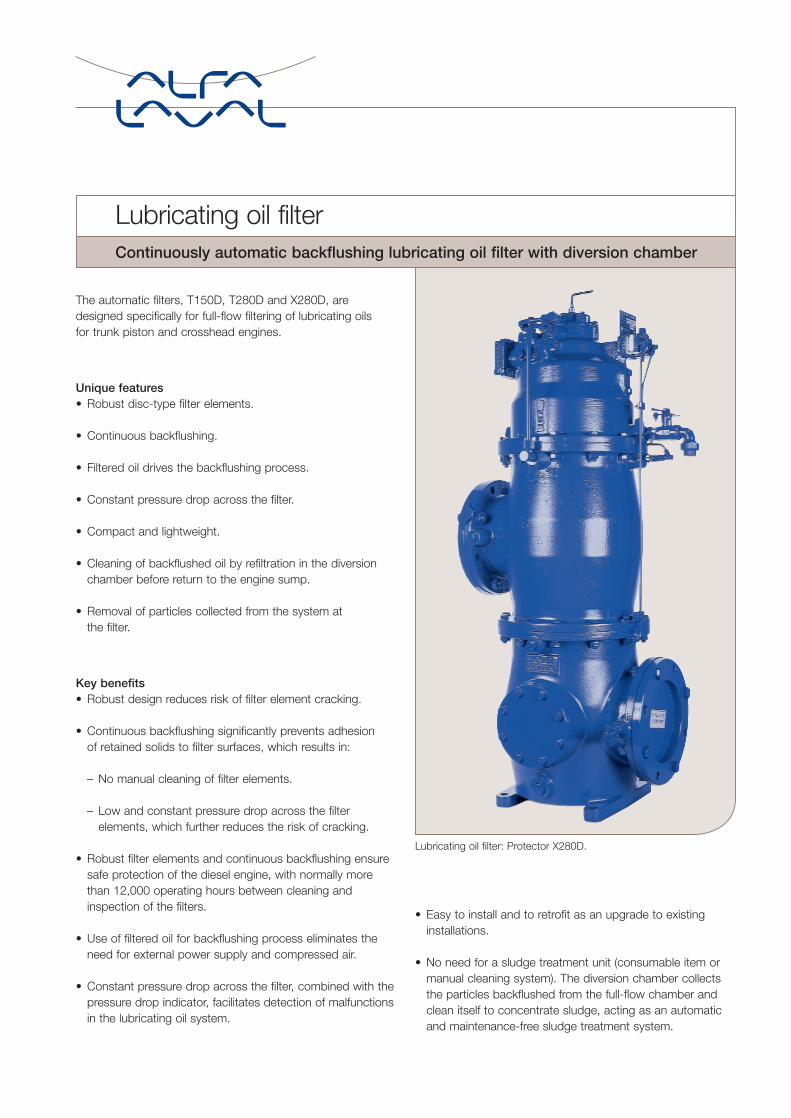
The automatic filters, T150D, T280D and X280D, aredesigned specifically for full-flow filtering of lubricating oils for trunk piston and crosshead engines.
Unique features• Robust disc-type filter elements.
• Continuous backflushing.
• Filtered oil drives the backflushing process.
• Constant pressure drop across the filter.
• Compact and lightweight.
• Cleaning of backflushed oil by refiltration in the diversionchamber before return to the engine sump.
• Removal of particles collected from the system at the filter.
Key benefits• Robust design reduces risk of filter element cracking.
• Continuous backflushing significantly prevents adhesion of retained solids to filter surfaces, which results in:
– No manual cleaning of filter elements.
– Low and constant pressure drop across the filterelements, which further reduces the risk of cracking.
• Robust filter elements and continuous backflushing ensuresafe protection of the diesel engine, with normally morethan 12,000 operating hours between cleaning andinspection of the filters.
• Use of filtered oil for backflushing process eliminates theneed for external power supply and compressed air.
• Constant pressure drop across the filter, combined with thepressure drop indicator, facilitates detection of malfunctionsin the lubricating oil system.
• Easy to install and to retrofit as an upgrade to existinginstallations.
• No need for a sludge treatment unit (consumable item ormanual cleaning system). The diversion chamber collectsthe particles backflushed from the full-flow chamber andclean itself to concentrate sludge, acting as an automaticand maintenance-free sludge treatment system.
Lubricating oil filter: Protector X280D.
Lubricating oil filterContinuously automatic backflushing lubricating oil filter with diversion chamber
Diesel engine protectionThe separator is installed in the bypass system. Its function is the removal of harmful contaminants (solid particles andwater) from the lubricating oil system.
The filter is installed in the full-flow system as close to theengine as possible to stop harmful solid particles that maynot have been removed by the separator. These particlescan then be removed from the system at the drain valveon the filters.
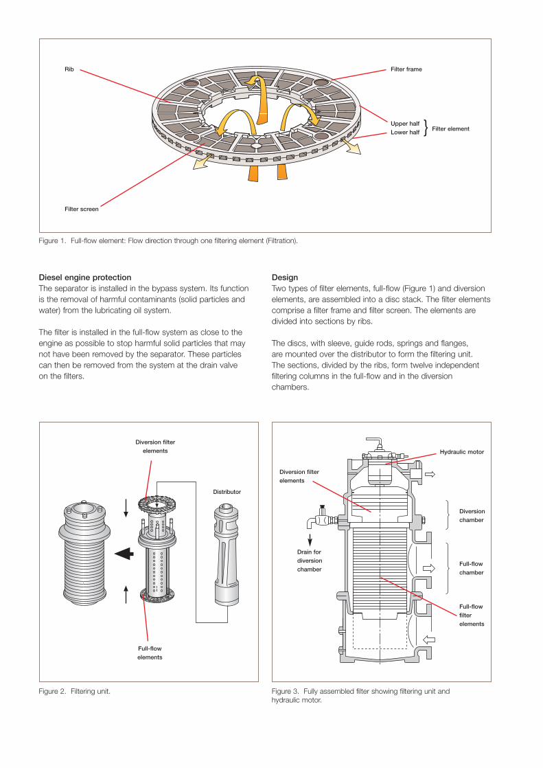
DesignTwo types of filter elements, full-flow (Figure 1) and diversionelements, are assembled into a disc stack. The filter elementscomprise a filter frame and filter screen. The elements aredivided into sections by ribs.
The discs, with sleeve, guide rods, springs and flanges, are mounted over the distributor to form the filtering unit. The sections, divided by the ribs, form twelve independentfiltering columns in the full-flow and in the diversionchambers.
Figure 2. Filtering unit. Figure 3. Fully assembled filter showing filtering unit and hydraulic motor.
Figure 1. Full-flow element: Flow direction through one filtering element (Filtration).
Rib
Filter screen
Filter frame
Upper halfLower half
Filter element}
Diversion filterelements Hydraulic motor
Diversion filterelements
Drain fordiversionchamber
Diversionchamber
Full-flowchamber
Full-flowfilterelements
Distributor
Full-flowelements
Operating principleThe unfiltered oil entering the filter is fed by the distributor to 11 of the 12 full-flow filtering columns. Solids are collectedon the filter surface and the filtered oil flows to the engine.Previously collected solids are removed in the twelfth column by backflushing with a small amount of the filtered oil andtaken through a passage in the distributor to the diversionchamber.
The distributor, which is driven by the hydraulic motor on top of the filter housing, rotates at regular intervals to feed oil for filtration in 11 columns and to backflush in the twelfth.In this way, all the columns are backflushed once per fullrotation of the distributor, which corresponds to every one to three minutes.
Backflushed oil is filtered in 11 of the 12 columns. Solids fromthe backflushed oil are directed to the diversion chamber.Cleaned backflushed oil is then led back to the lubricating oil sump. At the same time backflushing of the diversionchamber by clean oil takes place in the twelfth column andsolids settle to the bottom of the diversion chamber, wherethey are discharged periodically through the drain cock.
The pressure drop indicator connected between the inlet andoutlet of the full-flow chamber provides a reading and signalsan alarm condition if for any reason the pressure reaches the
alarm level. This indicates that there is a problem in the lubri-cating oil system.
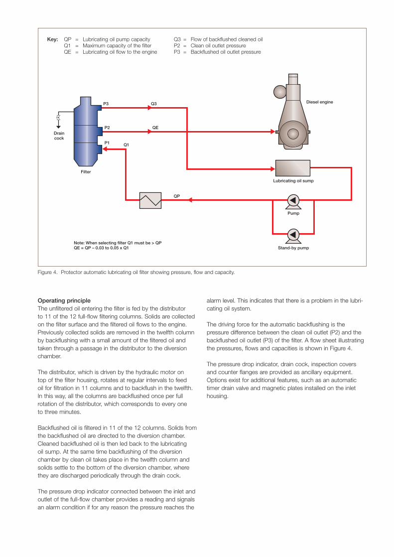
The driving force for the automatic backflushing is thepressure difference between the clean oil outlet (P2) and thebackflushed oil outlet (P3) of the filter. A flow sheet illustratingthe pressures, flows and capacities is shown in Figure 4.
The pressure drop indicator, drain cock, inspection coversand counter flanges are provided as ancillary equipment.Options exist for additional features, such as an automatictimer drain valve and magnetic plates installed on the inlethousing.
Filter
P2
P3 Q3
QE
Diesel engine
QP
Lubricating oil sump
Stand-by pumpNote: When selecting filter Q1 must be > QPQE = QP – 0.03 to 0.05 x Q1
P1 Q1
Pump
Draincock
Figure 4. Protector automatic lubricating oil filter showing pressure, flow and capacity.
Key: QP = Lubricating oil pump capacityQ1 = Maximum capacity of the filterQE = Lubricating oil flow to the engine
Q3 = Flow of backflushed cleaned oilP2 = Clean oil outlet pressureP3 = Backflushed oil outlet pressure
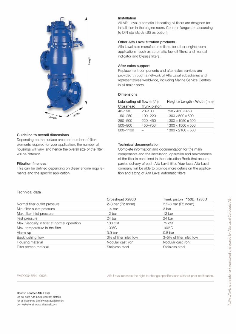
Guideline to overall dimensionsDepending on the surface area and number of filterelements required for your application, the number ofhousings will vary, and hence the overall size of the filterwill be different.
Filtration finenessThis can be defined depending on diesel engine require-ments and the specific application.
InstallationAll Alfa Laval automatic lubricating oil filters are designed forinstallation in the engine room. Counter flanges are accordingto DIN standards (JIS as option).
Other Alfa Laval filtration productsAlfa Laval also manufactures filters for other engine roomapplications, such as automatic fuel oil filters, and manualindicator and bypass filters.
After-sales supportReplacement components and after-sales services areprovided through a network of Alfa Laval subsidiaries andrepresentatives worldwide, including Marine Service Centresin all major ports.
Dimensions
Lubricating oil flow (m3/h) Height × Length × Width (mm)Crosshead Trunk piston40–150 20–100 750 × 450 × 450150–250 100–220 1300 × 500 × 500250–500 220–450 1300 × 1050 × 500500–800 450–700 1300 × 1500 × 500800–1100 – 1300 × 2100 × 500
Technical documentationComplete information and documentation for the maincomponents and the installation, operation and maintenanceof the filter is contained in the Instruction Book that accom-panies delivery of each Alfa Laval filter. Your local Alfa Lavalcompany will be able to provide more details on the applica-tion and sizing of Alfa Laval automatic filters.
EMD00048EN 0606 Alfa Laval reserves the right to change specifications without prior notification.
ALF
A L
AVA
L is
a t
rade
mar
k re
gist
ered
and
ow
ned
by A
lfa L
aval
Cor
pora
te A
B.
How to contact Alfa LavalUp-to-date Alfa Laval contact details for all countries are always available onour website at www.alfalaval.com
LengthWidth
Hei
ght
Technical data
Crosshead X280D Trunk piston T150D, T280DNormal filter outlet pressure 2–3 bar (P2 norm) 3.5–6 bar (P2 norm)Min. filter outlet pressure 1.4 bar 3 barMax. filter inlet pressure 12 bar 12 barTest pressure 24 bar 24 barMax. viscosity in filter at normal operation 130 cSt 75 cStMax. temperature in the filter 100°C 100°CAlarm ∆p 0.9 bar 0.8 barBackflushing flow 3% of filter inlet flow 3–5% of filter inlet flowHousing material Nodular cast iron Nodular cast ironFilter screen material Stainless steel Stainless steel