lubrication system - warzone.elhacker.netquads.ddns.net/service-manuals/kymco/mo mxu500...
TRANSCRIPT

4. LUBRICATION SYSTEM
4-0
MXU 500
4 __________________________________________________________________________________
__________________________________________________________________________________
__________________________________________________________________________________
__________________________________________________________________________________
__________________________________________________________________________________
LUBRICATION SYSTEM__________________________________________________________________________________
LUBRICATION SYSTEM DIAGRAM --------------------------------- 4- 1SERVICE INFORMATION----------------------------------------------- 4- 2TROUBLESHOOTING---------------------------------------------------- 4- 3LUBRICATION CHECK HOLE ----------------------------------------- 4- 4OIL PUMP REMOVAL/INSPECTION/INSTALLATION----------- 4- 5OIL PUMP DISASSEMBLY/INSPECTION/ASSEMBLY ---------- 4- 9RIGHT CRANKCASE COVER DISASSEMBLY/ASSEMBLY---- 4-12OIL PRESSURE RELIEF VALVE--------------------------------------- 4-14OIL PIPE REMOVAL/INSTALLATION------------------------------- 4-15
4

4. LUBRICATION SYSTEM
4-1
MXU 500
LUBRICATION SYSTEM DIAGRAM

4. LUBRICATION SYSTEM
4-2
MXU 500
SERVICE INFORMATION
GENERAL INSTRUCTIONS• The oil pump service may be done with the engine installed in the frame.• When removing and installing the oil pump use care not to allow dust or dirt to enter the engine.• If any portion of the oil pump is worn beyond the specified service limits, replace the oil pump as
an assembly.• After the engine has been installed check that there are no oil leaks and that oil pressure is
correct.
SPECIFICATIONS Unit: mm (in)
ITEM STANDARD SERVICE LIMITAt draining 3 liter (2.64 lmp qt, 3.18 Us qt) ⎯
At disassembly 3.6 liter (3.17 lmp qt, 3.82 Us qt) ⎯Engine oilcapacity
At draining and oilfilter cartridge change 3.2 liter (2.82 lmp qt, 3.39 Us qt) ⎯
Recommended engine oil
KYMCO 4-stroke oil or equivalentmotor oilAPI service classification SJViscosity: SAE 5W-50
⎯
Tip clearance 0.15 (0.006) max 0.2 (0.008)Body clearance 0.15 – 0.2 (0.006 – 0.008) 0.25 (0.01)Oil pump rotor
Side clearance 0.04 – 0.09 (0.0016 – 0.0036) 0.12 (0.0048)
TORQUE VALUES
Oil pump screw 0.3 kgf-m (3 N-m, 2 lbf-ft)Oil strainer screen cap 1.5 kgf-m (15 N-m, 11 lbf-ft) Apply oil to the threads and seating surface.Oil filter cartridge 1 kgf-m (10 N-m, 7 lbf-ft) Apply oil to the threads and seating surface.Oil pipe bolt 3.5 kgf-m (35 N-m, 25.2 lbf•ft)
Apply oil to the threads and seating surface.
Special tool:Oil seal & bearing drive A120E00014

4. LUBRICATION SYSTEM
4-3
MXU 500
TROUBLESHOOTINGOil level low High oil pressure• Oil consumption • Pressure relief valve stuck closed• External oil leak • Plugged oil filter, gallery, or metering orifice• Worn piston ring • Faulty oil pump• Incorrect piston ring installation• Worn valve guide or seal Seized engine
• No or low oil pressureOil contamination (White appearance) • Clogged oil orifice/passage• From coolant mixing with oil • Internal oil leak ─ Faulty water pump mechanical seal • Non-recommended oil used ─ Faulty head gasket ─ Water leak in crankcase Oil contamination
• Deteriorated oilNo oil pressure • Faulty oil filter• Oil level too low • Worn piston ring (White appearance with water or• Oil pump drive chain broken moisture)• Oil pump drive sprocket broken ─ Damaged water pump mechanical seal• Oil pump damaged (pump shaft) ─ Damaged head gasket• Internal oil leak ─ Oil relief not frequent enough
Low oil pressure• Pressure relief valve stuck open• Clogged oil filter and strainer screen• Oil pump worn or damaged• Internal oil leak• Incorrect oil being used• Oil level too low
4. LUBRICATION SYSTEM
4-4
MXU 500
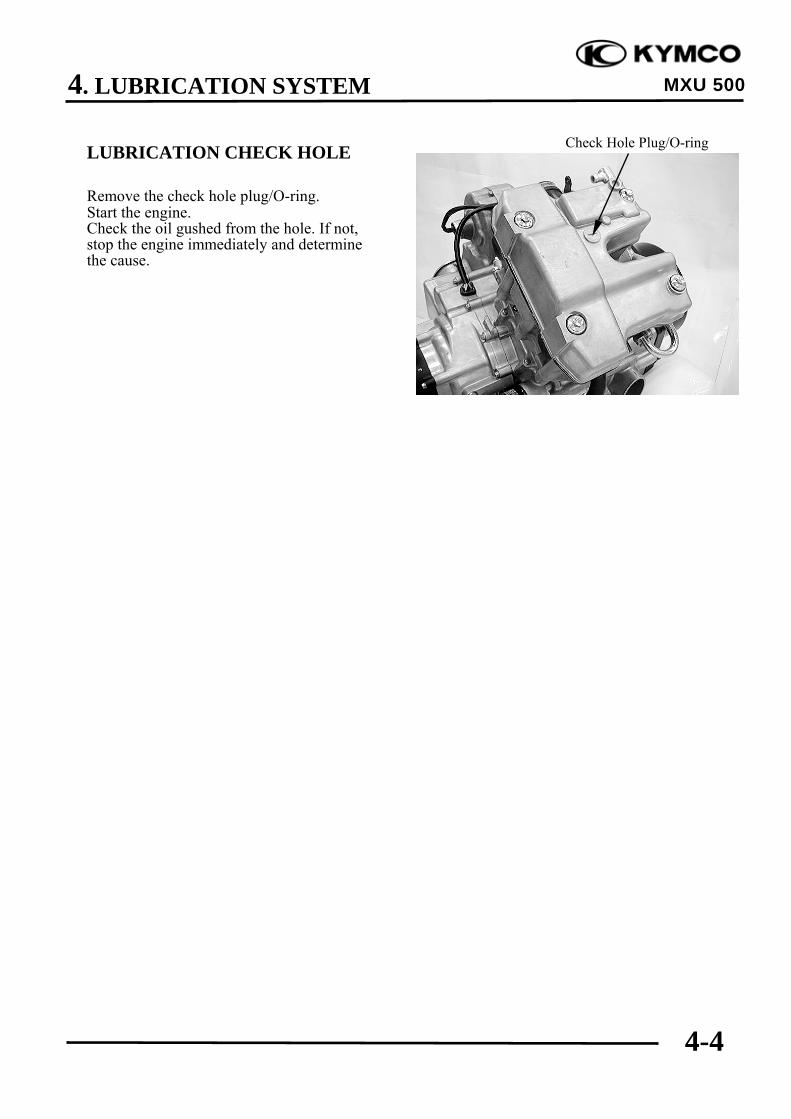
LUBRICATION CHECK HOLE
Remove the check hole plug/O-ring.Start the engine.Check the oil gushed from the hole. If not,stop the engine immediately and determinethe cause.
Check Hole Plug/O-ring
4. LUBRICATION SYSTEM
4-5
MXU 500
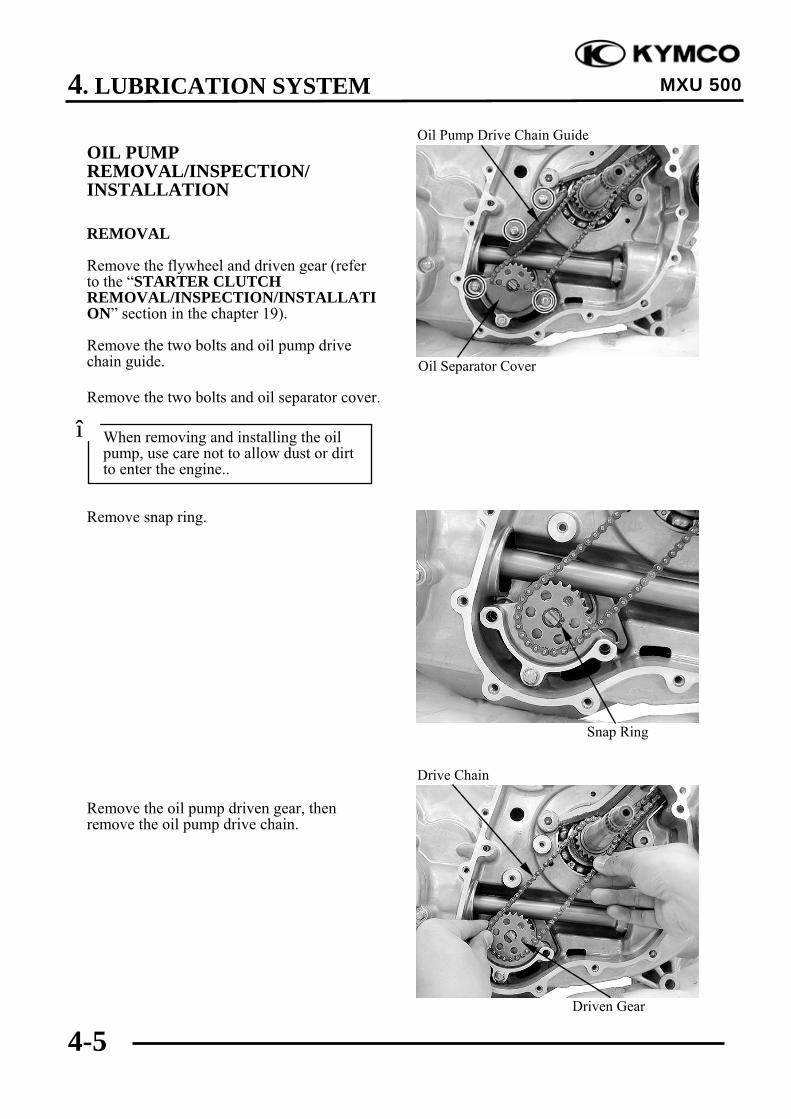
OIL PUMPREMOVAL/INSPECTION/INSTALLATION
REMOVAL
Remove the flywheel and driven gear (referto the “STARTER CLUTCHREMOVAL/INSPECTION/INSTALLATION” section in the chapter 19).
Remove the two bolts and oil pump drivechain guide.
Remove the two bolts and oil separator cover.
Remove snap ring.
Remove the oil pump driven gear, thenremove the oil pump drive chain.
Oil Separator Cover
Oil Pump Drive Chain Guide
Driven Gear
Drive Chain
Snap Ring
When removing and installing the oilpump, use care not to allow dust or dirtto enter the engine..
*

4. LUBRICATION SYSTEM
4-6
MXU 500
Remove a bolt and then remove the oil pumpholder.Remove the two dowel pins.
Remove the two bolts and then remove the oilpump.
INSPECTION
Oil pump drive chain guide
Inspect the drive chain slipper surface of thedrive chain guide for wear or damage.
INSTALLATION
Install the oil pump.
Holder Oil Pump
Dowel Pins
Slipper Surface
Oil Pump
Make sure the pump shaft rotates freelyand arrow on the oil pump is upside.*

4. LUBRICATION SYSTEM
4-7
MXU 500
Install and tighten the two bolts securely.Install two dowel pins
Install the holder, then install a bolt but donot tighten.
Install the driven gear and drive chain.
Install the snap ring.
Driven Gear
Drive Chain
Snap Ring
Oil Pump Holder
Dowel Pins
4. LUBRICATION SYSTEM
4-8
MXU 500
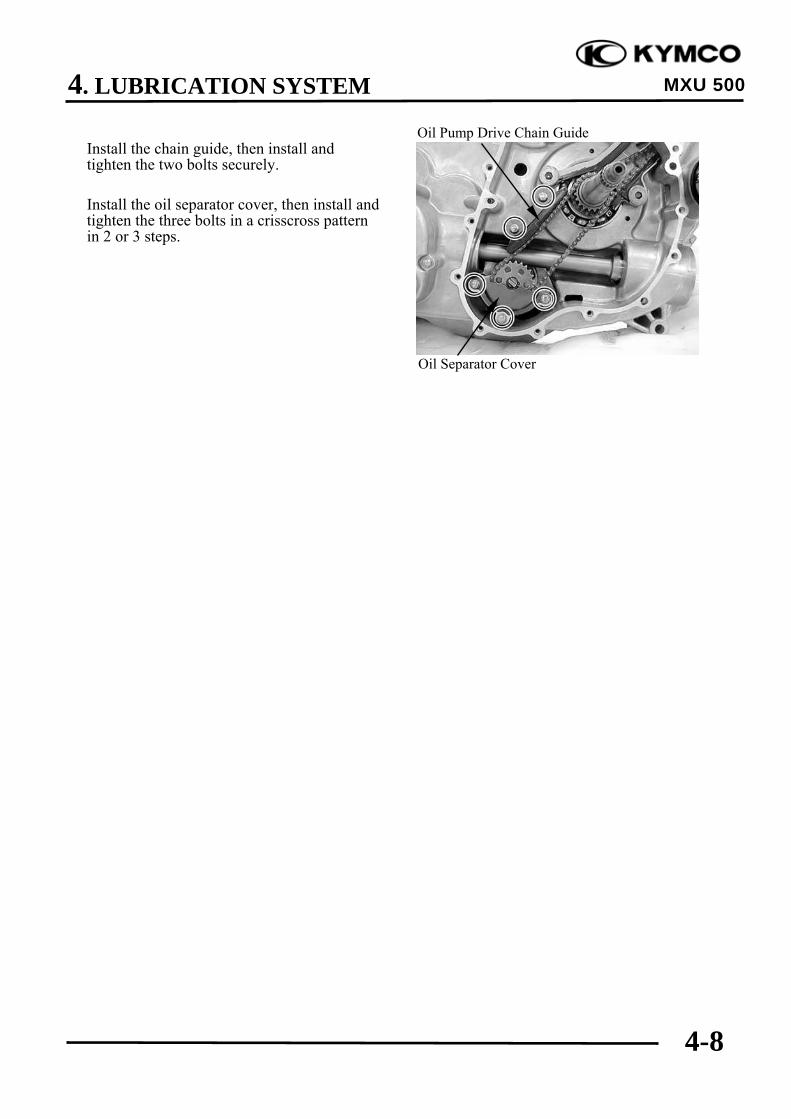
Install the chain guide, then install andtighten the two bolts securely.
Install the oil separator cover, then install andtighten the three bolts in a crisscross patternin 2 or 3 steps.
Oil Separator Cover
Oil Pump Drive Chain Guide
4. LUBRICATION SYSTEM
4-9
MXU 500
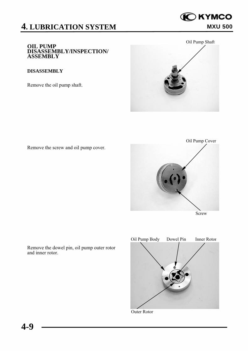
OIL PUMPDISASSEMBLY/INSPECTION/ASSEMBLY
DISASSEMBLY
Remove the oil pump shaft.
Remove the screw and oil pump cover.
Remove the dowel pin, oil pump outer rotorand inner rotor.
Oil Pump Shaft
Outer Rotor
Oil Pump Body Dowel Pin Inner Rotor
Screw
Oil Pump Cover

4. LUBRICATION SYSTEM
4-10
MXU 500
INSPECTION
Temporarily install the oil pump shaft.Install the outer and inner rotors into the oilpump body.
Measure the tip clearance.
Service limit: 0.2 mm (0.008 in)
Measure the pump body clearance.
Service limit: 0.25 mm (0.01 in)
Measure the side clearance with the straightedge and feeler gauge.
Service limit: 0.12 mm (0.0048 in)
Measure at several points and use thelargest reading to compare the servicelimit.
*

4. LUBRICATION SYSTEM
4-11
MXU 500
ASSEMBLY
Dip all parts in clean engine oil.
Install the outer rotor into the oil pump body.Install the inner rotor into the outer rotor.Install the oil pump shaft.Install the dowel pin onto the oil pump body.Install the oil pump cover onto the oil pumpbody by aligning the dowel pin.
Install and tighten the screw to the specifiedtorque.
Torqur: 3 N•m (0.3kgf•m, 2 lbf•ft)
Dowel Pin Oil Pump Cover
Screw
Oil Pump Cover
4. LUBRICATION SYSTEM
4-12
MXU 500
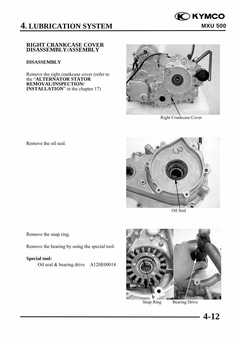
RIGHT CRANKCASE COVERDISASSEMBLY/ASSEMBLY
DISASSEMBLY
Remove the right crankcase cover (refer tothe “ALTERNATOR STATORREMOVAL/INSPECTION/INSTALLATION” in the chapter 17)
Remove the oil seal.
Remove the snap ring.
Remove the bearing by using the special tool.
Special tool:Oil seal & bearing drive A120E00014
Right Crankcase Cover
Snap Ring Bearing Drive
Oil Seal

4. LUBRICATION SYSTEM
4-13
MXU 500
ASSEMBLY
Install a new bearing by using the specialtool.
Special tool:Oil seal & bearing drive A120E00014
Install a new oil seal.
Bearing Drive Snap Ring
Oil Seal
4. LUBRICATION SYSTEM
4-14
MXU 500
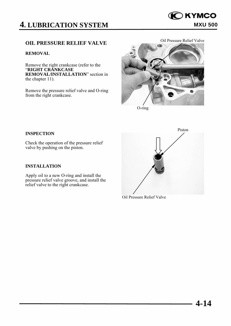
OIL PRESSURE RELIEF VALVE
REMOVAL
Remove the right crankcase (refer to the“RIGHT CRANKCASEREMOVAL/INSTALLATION” section inthe chapter 11).
Remove the pressure relief valve and O-ringfrom the right crankcase.
INSPECTION
Check the operation of the pressure reliefvalve by pushing on the piston.
INSTALLATION
Apply oil to a new O-ring and install thepressure relief valve groove, and install therelief valve to the right crankcase.
Oil Pressure Relief Valve
Piston
O-ring
Oil Pressure Relief Valve

4. LUBRICATION SYSTEM
4-15
MXU 500
OIL PIPEREMOVAL/INSTALLATION
REMOVAL
Remove the two bolts, washers (on the oilpipe), oil pipe and washers (under oil pipe).
INSTALLATIION
Install the inner washers on the rightcrankcase.
Install the oil pipe with the thick side faceupward.
Oil Pipe/Washer (under oil pipe)
Oil Pipe
Thick Side
Washers
Bolts/Washers (on the oil pipe)

4. LUBRICATION SYSTEM
4-16
MXU 500
Apply clean engine oil to the bolts, theninstall the outer washers and two bolts.Tighten the two bolts to the specified torque.
Torque: 3.5 kgf-m (35 N-m, 25.2 lbf•ft)
Oil Pipe/Washers (under oil pipe)
Bolts/Washers (on the oil pipe)