lucky seven game using 7 segment display in fpga
TRANSCRIPT
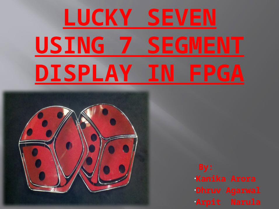
LUCKY SEVEN USING 7
SEGMENT DISPLAY IN FPGA
By:•Kanika Arora•Dhruv Agarwal•Arpit Narula

INTRODUCTION A field-programmable gate
array (FPGA) is an integrated circuit designed to be configured by a customer or a designer after manufacturing .
The FPGA configuration is generally specified using a hardware description language(HDL), similar to that used for an application-specific integrated circuit(ASIC).
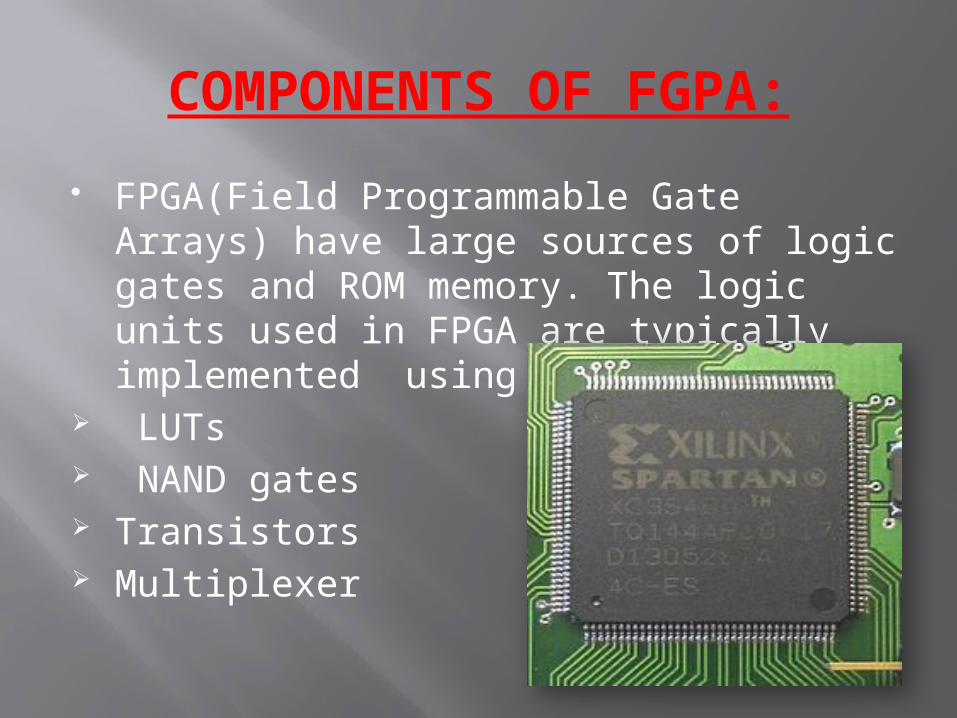
COMPONENTS OF FGPA: FPGA(Field Programmable Gate Arrays)
have large sources of logic gates and ROM memory. The logic units used in FPGA are typically implemented using :
LUTs NAND gates Transistors Multiplexer
7 Segment Display: A seven-segment display (SSD),
or seven-segment indicator, is a form of electronic display device for displaying decimal numerals that is an alternative to the more complex dot matrix displays.
Applications: Seven-segment displays are widely used
in digital clocks, electronic meters, basic calculators, and other electronic devices that display numerical information.
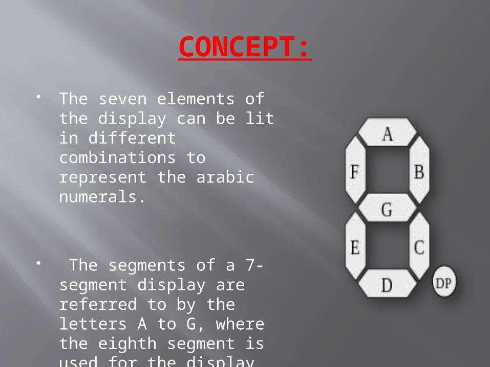
CONCEPT: The seven elements of
the display can be lit in different combinations to represent the arabic numerals.
The segments of a 7-segment display are referred to by the letters A to G, where the eighth segment is used for the display of non-integer numbers.
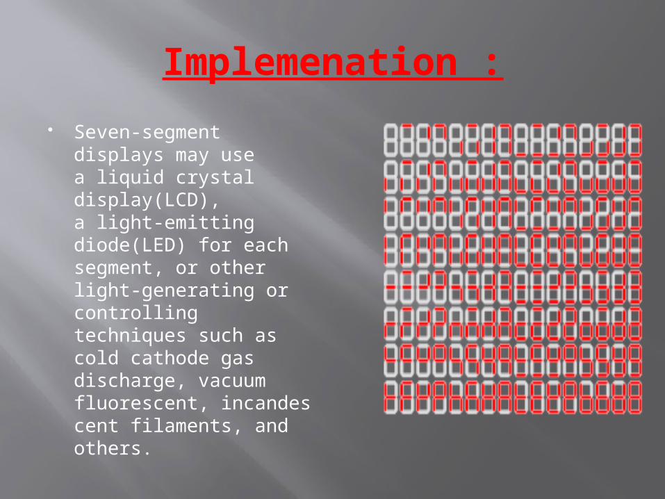
Implemenation : Seven-segment
displays may use a liquid crystal display(LCD), a light-emitting diode(LED) for each segment, or other light-generating or controlling techniques such as cold cathode gas discharge, vacuum fluorescent, incandescent filaments, and others.
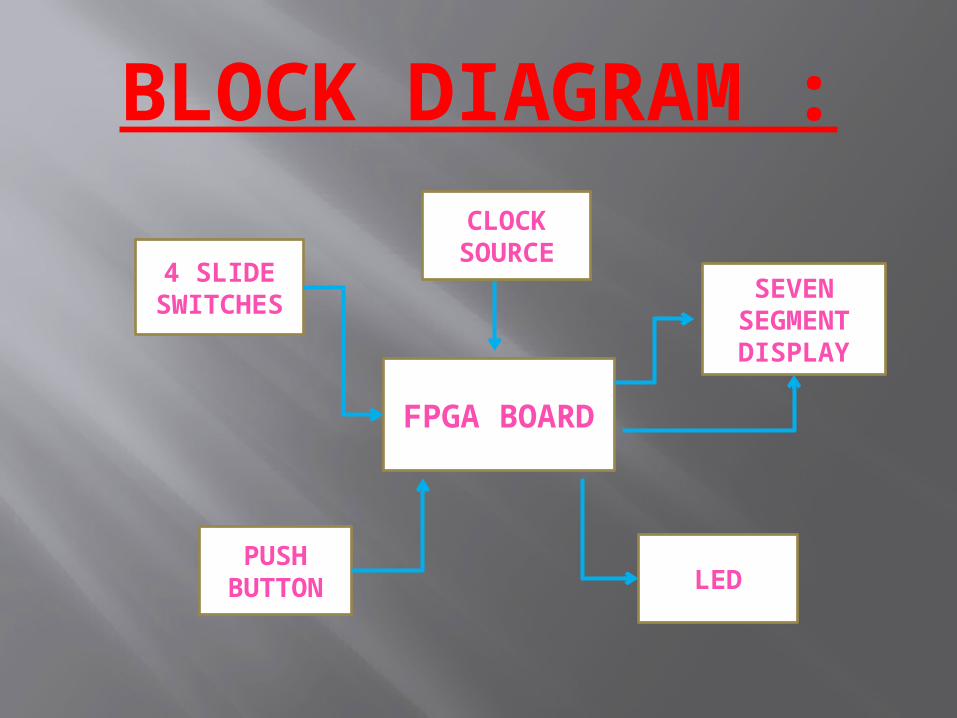
BLOCK DIAGRAM :
FPGA BOARD
CLOCK SOURCE
SEVEN SEGMENT DISPLAY
4 SLIDE SWITCHE
S
PUSH BUTTON LED
The above block diagram consist of 2 outputs and 2 inputs.
Firstly a delay and count is given by the FPGA clock which generates increasing numbers on the seven segment displays. Inputs: 4 Slide Switches and a Push Button.
The 4 slide switches are used to stop the counter of each seven segment display, that is, as soon as we switch on the switch, the number on the corresponding seven segment freezes.
The push button is used to reset the counter, as the button is pressed,
all the four seven segment displays go back to zero and start over again afresh. Outputs: 4 Seven Segment Display and all LEDs.
The seven segment displays are used throughout the project to display the numbers on them in increasing fashion or freeze state. The main purpose of using LEDs in this project is to indicate that the player wins the game as it will glow only when all the switches are high as well as the numbers on all the seven segment displays are identical.
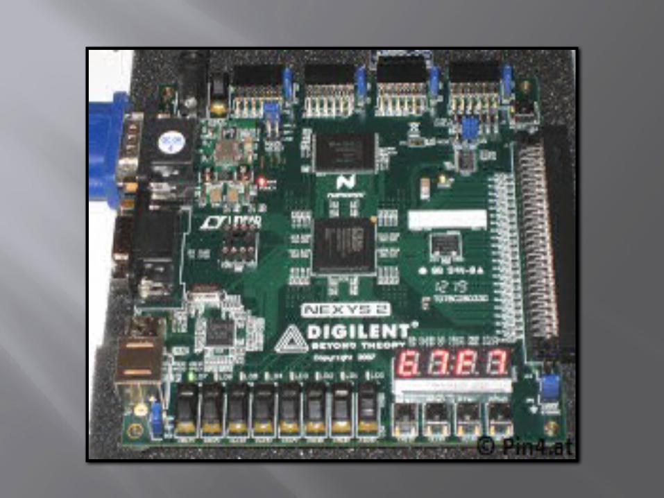
HARDWARE The Nexys 3 Spartan 6 FPGA board consists of five push
buttons of which we make use of the central push button for the reset purpose. We make use of all 4 seven segment LED displays available on the board and also 4 out of 8 slide switches are used. This board has 8 LED and we use all of them to signify the winning situation. The FPGA board connects to the Xilinx software in computer with the help of a USB cable connected to the USB port on the board . This USB cable supplies power to the FPGA board and is also used to implement the program code on the hardware. The main component of the hardware is the application based integrated circuit (ASIC) named as Nexys 3 Spartan-6 which works at the frequency of 50 MHz .
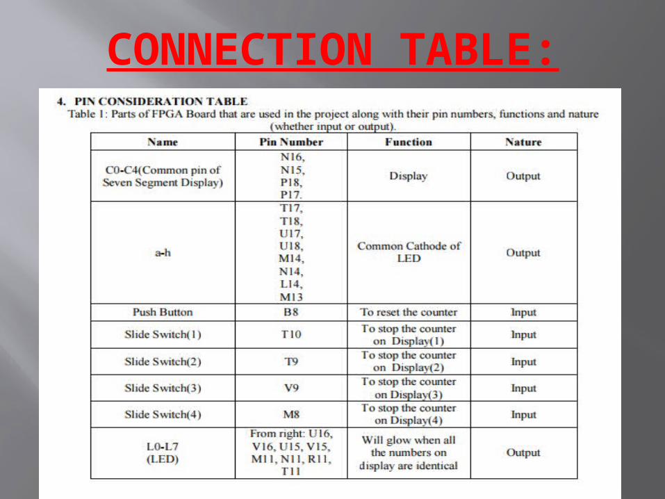
CONNECTION TABLE:
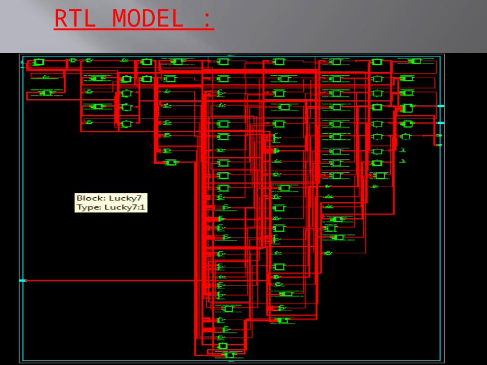
RTL MODEL :
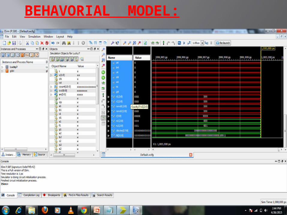
BEHAVORIAL MODEL:
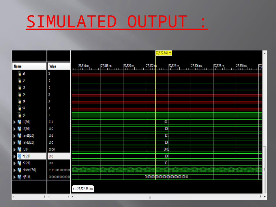
SIMULATED OUTPUT :
APPLICATION: This implementation of lucky 7 can be used in casino
gaming instead of the game slots. It can also be used in the restaurants for the order number machines which would look fascinating to display a customer’s order number while glowing LED.
RESULT After the implementation of a code written in Xilinx based on
the sequence of the block diagram, the numbers run from 0 to 9 on all the four seven segment display and are controlled by individual switches. When the switch is turned on the number on the corresponding seven segment freezes. When all the four switches are on the when the number frozen on the four seven segments are same, the LED lights on the Spartan 6 board glow, representing the winning position.

THANK YOU !!