ludv control block of sandwich re 64132/05.09 plate design · maximum pressure, pump side 250 bar...
TRANSCRIPT

Nominal size 10Series 1XMaximum pressure, pump side 250 barMaximum pressure, actuator side 300 barInlet flow 80 l/mnFlow at each directional valve element 50 l/mn
LUDV control block of sandwich plate design
RE 64132/05.09 1/14Replaces: 12.02
Type SX 10
– Distributes the flow between the directional valve elements according to the requirements, independently of the pressure and available flow.
– Compact sandwich plate design, can be combined so that the control block can meet the requirements of differing machines.
– No shuttle valves.– Limitation of system maximum pressure via LS pressure
relief valve.– System protection via LS and secondary pressure relief
valves.
Special featuresContents
Special features 1Functional description, Section 2Hydraulic Symbol 2Technical data 3 to 4Ordering details 5 to 7Inlet element - Final element 8Directional valve element 9 to 10Unit dimensions (in mm) 11 to 13Assembly possibilities 14Pipe connections 14
2/14 Bosch Rexroth AG Hydraulics SX 10 | RE 64132/05.09
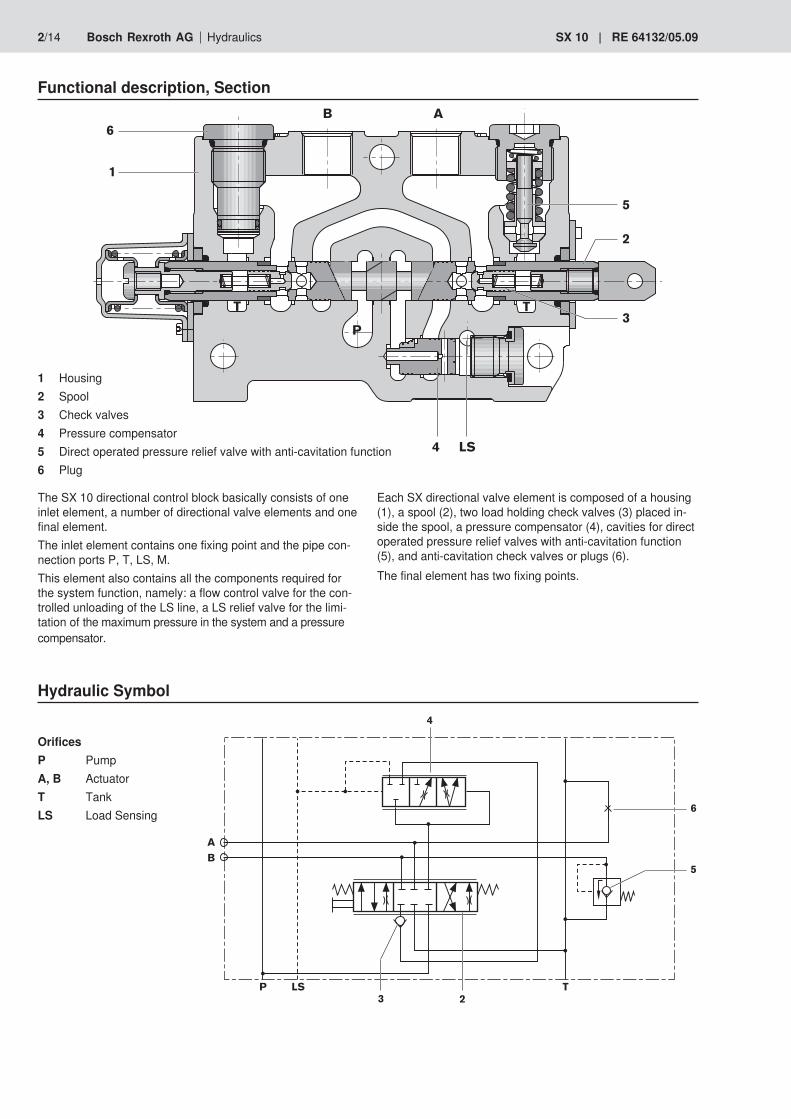
Functional description, Section
1 Housing2 Spool3 Check valves4 Pressure compensator5 Direct operated pressure relief valve with anti-cavitation function6 Plug
The SX 10 directional control block basically consists of one inlet element, a number of directional valve elements and one final element. The inlet element contains one fixing point and the pipe con-nection ports P, T, LS, M.This element also contains all the components required for the system function, namely: a flow control valve for the con-trolled unloading of the LS line, a LS relief valve for the limi-tation of the maximum pressure in the system and a pressure compensator.
Each SX directional valve element is composed of a housing (1), a spool (2), two load holding check valves (3) placed in-side the spool, a pressure compensator (4), cavities for direct operated pressure relief valves with anti-cavitation function (5), and anti-cavitation check valves or plugs (6).The final element has two fixing points.
OrificesP PumpA, B ActuatorT TankLS Load Sensing
�
�� �
�
�
�
�
�
��
��
��
� �� �
�
�
�
��
Hydraulic Symbol
3/14RE 64132/05.09 | SX 10 Hydraulics Bosch Rexroth AG
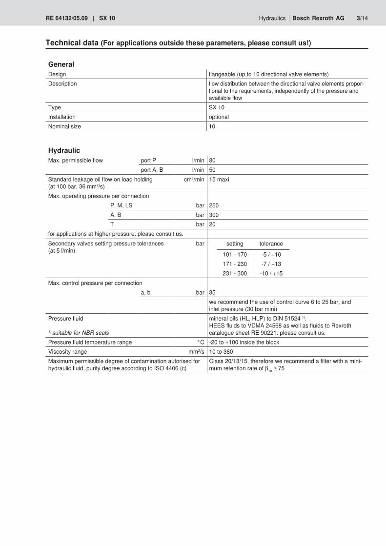
GeneralDesign flangeable (up to 10 directional valve elements)Description flow distribution between the directional valve elements propor-
tional to the requirements, independently of the pressure and available flow
Type SX 10 Installation optional Nominal size 10
HydraulicMax. permissible flow port P l/min 80
port A, B l/min 50Standard leakage oil flow on load holding (at 100 bar, 36 mm2/s)
cm3/min 15 maxi
Max. operating pressure per connectionP, M, LS bar 250A, B bar 300T bar 20
for applications at higher pressure: please consult us.Secondary valves setting pressure tolerances (at 5 l/min)
bar
Max. control pressure per connection a, b bar 35
we recommend the use of control curve 6 to 25 bar, and inlet pressure (30 bar mini)
Pressure fluid
1) suitable for NBR seals
mineral oils (HL, HLP) to DIN 51524 1).HEES fluids to VDMA 24568 as well as fluids to Rexroth catalogue sheet RE 90221: please consult us.
Pressure fluid temperature range °C -20 to +100 inside the blockViscosity range mm2/s 10 to 380Maximum permissible degree of contamination autorised for hydraulic fluid, purity degree according to ISO 4406 (c)
Class 20/18/15, therefore we recommend a filter with a mini-mum retention rate of β10 ≥ 75
Technical data (For applications outside these parameters, please consult us!)
setting tolerance
101 - 170 -5 / +10171 - 230 -7 / +13231 - 300 -10 / +15

4/14 Bosch Rexroth AG Hydraulics SX 10 | RE 64132/05.09
Installation guidelinesPipe connections
P, P2 T, T3 M, LS, T1 A, B, T2 a, b
Tightening torque for the pipe connections Nm 50 50 20 30 20Recommended fixing at 3 locationsFlatness of the mounting surface mm 0.5Setting of system pressureThe hydraulic circuit may not generate any un-controlled leak flow in the LS line
via the LS pressure relief valve
Do not direct the jet of a pressure washing unit directly at the unit
MechanicalWeight Inlet element kg 5Directional valve element kg 2.1Blanking plate kg 2
Spool return force N 55 to 95 (with standard spring)Max. permissible actuation force on the spool (for 1 million cycles)- axial N 1000 during 20% of total cycles then 500- radial N 16Storage temperature °C -40 to +60
Technical data (For applications outside these parameters, please consult us!)

5/14RE 64132/05.09 | SX 10 Hydraulics Bosch Rexroth AG
SX 10 L 1X ..0
Number or directional valve spools 1 to 10Medium pressure = Lseries 10 to 19 = 1X(10 to 19, unchanged installation and connection dimensions)Inlet elementClosed Center withflushing valve = S Open Center = P 1) Max. pressure in bar, measured at M, ad-justable via the LS pressure relief valve
1st directional valve element..0 ..0
2nd directional valve element..0 ..0
3rd directional valve element..0 ..0
4th directional valve element..0 ..0
5th directional valve element..0 ..0
6th directional valve element..0 ..0
7th directional valve element..0 ..0
8th directional valve element..0 ..0
9th directional valve element..0 ..0
10th directional valve element
..0 ..0
Dire
ctio
nal v
alve
spo
ol
Flow
at c
onne
ctio
n po
rt "A
" (in
l/m
m)
Flow
at c
onne
ctio
n po
rt "B
" (in
l/m
m)
Type
of o
pera
tion
Ope
ratio
n or
ient
atio
n
Seco
ndar
y va
lve a
t con
nect
ion
port
"A"
Seco
ndar
y va
lve a
t con
nect
ion
port
"B"
Ordering details: see page 6
SealsM = NBR seals
! Attention!The compatibility of the seals and pressure fluid has to be
taken into account
Connection threads01 = Pipe threads to standard ISO 228/1A, B, T2 = G 3/8p, P2, T, T3 = G 1/2M, LS, T1 = G 1/4a, b = G 1/4
Further details in clear text
M *
Final element L = Blanking plateLT = Blanking plate
with outlet T3
1) set with a ∆p of 15 bar between M and LS
Ordering details: SX 10 directional control block
directional valve element1 to 10 elements
inlet element final element
-
-
-
-
-
-
-
-
-
-

6/14 Bosch Rexroth AG Hydraulics SX 10 | RE 64132/05.09
port
"A"
port
"B"
Secondary valvesH..0* = direct actuated pressure relief valve with anti-cavitation function * = pressure value in barE = anti-cavitation check valveQ = plug
Operation orientationNo code = without mechanical operator (H200)A = mechanical operator on connection side AB = mechanical operator on connection side B
Type of operationA2 = 3 positions spool return via a springE2 = 4 positons spool return via a springZ1 = mechanical operator with tongue (Ø 6)H 200 = hydraulic operator, spool return via a springH 230 = hydraulic operator, spool return via a spring,
stroke limitation on connection sides A and BFlow at connection ports
050 = flow at connection port B in l/min Other flow values (rated in 10 l/min ranges): please consult us050 = flow at connection port A in l/min Other flow values (rated in 10 l/min ranges): please consult us
Directional valve spools
� �
� �
� � � = EA
� �
� � � = JA
� �
� � � = QA
= WA
Ordering details: additional details for the directional valve element (page 5)
-
� �
� � ��

7/14RE 64132/05.09 | SX 10 Hydraulics Bosch Rexroth AG
Ordering details: separate element
Inlet element SX 10 1X ..0 M *
see ordering details page 5
see ordering details of inlet element page 5
Directional valve ele-ment
SX 10 1X ..0 ..0 M *
see ordering details pages 5 and 6
see ordering details of directional valve element pages 5 and 6
Final element SX 10 1X M *
see ordering details page 5
see ordering details of final element page 5
Desired execution: 3 directional valve elements
Inlet element: Open Center, Max. pressure = 200 bar
3 directional valve elements: •1stand2ndelements: -Spoolsymbol=EA - Flow in A = 50 l/min, Flow in B = 50 l/min - Mechanical operator with tongue on connection side A, spool return via a spring - Secondary valve in A = direct operated pressure relief valve with anti-cavitation function set at 250 bar - Secondary valve in B = plug •3rdelement: -Spoolsymbol=JA - Flow in A = 50 l/min, Flow in B = 50 l/min - Hydraulic operator, spool return via a spring - Secondary valves in A and B = anti-cavitation check valve
Final element: Blanking plat
Ordering details:inlet element
1st directional valve element
3 SX 10 L 1X P 200 EA 50 50 A2Z1 A H250 Q2nd directional valve element
EA 50 50 A2Z1 A H250 Q3rd directional valve element
JA 50 50 H200 E E L M 01
final element
Ordering example - complete block SX10
-
-
-
-

8/14 Bosch Rexroth AG Hydraulics SX 10 | RE 64132/05.09
Closed center with flushing valve Open centerOrdering detailS
Ordering detailP
Inlet element
Final element
Blanking plateOrdering detailL
Blanking plate with outlet T3Ordering detailLT
�
�
��
�
��
��
��
�
�
��
�
��
��
��
� �� �
� ��
��

9/14RE 64132/05.09 | SX 10 Hydraulics Bosch Rexroth AG
Directional valve element
��
� �� �
Representation of the SX directional valve elementSimplified symbol used to illustrate SX directional control circuits
Spool variationsOrdering detail
EA...-...: Symbol EA
� �
� �
� � �
JA...-...: Symbol JA� �
� � �
QA...-...: Symbol QA� �
� � �
WA...-...: Symbol WA� �
� � ��
Type of operatorMechanical operator with tongue on connection side A, spool return via a spring 3 positionsOrdering detailA2Z1A
Mechanical operator with tongue on connection side B, spool return via a spring 4 positonsCodificationE2Z1B �
�
� �� �
AB
P LS T

10/14 Bosch Rexroth AG Hydraulics SX 10 | RE 64132/05.09
Hydraulic operator, spool return via a spring
Ordering detailH200
Hydraulic operator with adjustable stop pins, spool return via a spring
Ordering detailH230
Secondary valves
Direct operated pressure relief valve with anti-cavitation function (on connection side A); plug (on connection side B)
Ordering detailH...Q
Anti-cavitation check valve (on connection side A); plug (on connection side B)
Ordering detailEQ
�
�
� �� �
� �
��
����
��
�� ��
��
� �� �
� �
Directional valve element

11/14RE 64132/05.09 | SX 10 Hydraulics Bosch Rexroth AG
Unit dimensions (in mm)
1 Inlet element2 Directional valve element3 Blanking plate4 Cover for hydraulic operator5 Stroke limitation and hydraulic connection6 Mechanical operator with tongue7 Cover for spring return arrangement8 LS flow control valve
(tightening torque = 20 ± 10% Nm)9 LS pressure relief valve
(tightening torque = 45 ± 10% Nm)10 Secondary pressure relief valve
(tightening torque = 30 to 35 Nm)11 3 tie rods (nuts tightening torque =
20 ± 10% Nm)
��� �������
��
�����
����
����
����
������
����
������
������
����
���
���
����
����
����
����
������ ���� ��
�� ��
������
����
������
����
��
��
��
��
��
��
��
��
��
�
�
�
�
�
�
�
�
��
�
�
�
��
���
����
�
��
��
�
���� ��
��� ��
�
��� ��
�
��� ��
�
��� ��
�
��� ��
�
��� ��
�
��� ��
�
��� ��
�
��� ��
�
��

12/14 Bosch Rexroth AG Hydraulics SX 10 | RE 64132/05.09
Inlet element
Mechanical or manual operators, spool return via a spring
Spool return via a spring Manual operators3 positionsOrdering detailA2
Ordering detailZ1
4 positionsOrdering detailE2
Tongue thickness 6 mm
���
�
������
��� �������
��
�����
����
����
����
�
��
��
���� ��
�� ���� ��
������
����
������
���� ����
��
��
�
��
��
�
����
�� ��
��
Unit dimensions (in mm)

13/14RE 64132/05.09 | SX 10 Hydraulics Bosch Rexroth AG
Final element
Blanking plate
Ordering detailL
Blanking plate with outlet T3Ordering detailLT
����
�������
��
����
��
��
����
����
���
��
����
��
Hydraulic operator, spool return via a springOrdering detailH200
Hydraulic operator with adjustable stop pin, spool return via a spring
Ordering detailH230
���
��
���
��
���� ����
���
��
���
��
���� ����
Unit dimensions (in mm)

14/14 Bosch Rexroth AG Hydraulics SX 10 | RE 64132/05.09
Pipe connections
1 Inlet element2 Directional valve element3 Blanking plate L4 Cover for hydraulic operator H2005 Cover for hydraulic operator H2306 Mechanical operator with tongue type Z17 Spring return arrangement type A2
Assembly possibilities
01
ports d1 Ød2 t1 t2
A, B, T2 G 3/8 - 14 1
P, P2, T, T3 G 1/2 34 14 1
M, LS, T1, a, b G 1/4 25 12 1
���� ��
���
�
�
��
�
�
�
�
�
�
�
��
��
�
�
��
�
�
��
��
��
8 LS flow control valve9 LS pressure relief valve10 Secondary pressure relief valve11 Plug for individual pressure compensator12 Plug13 Seals plate
RE 64132/05.09 | SX 10 Bosch Rexroth AG Hydraulics
Notes
Bosch Rexroth DSI S.A.S.BP 10191,bdIrèneJoliot-Curie69634 Vénissieux Cedex, FranceTelefon +33 (0) 4 78 78 52 52 Telefax +33 (0) 4 78 78 52 26www.boschrexroth.fr
© This document, as well as the data, specifications and other informati-on set forth in it, are the exclusive property of Bosch Rexroth AG. It may not be reproduced or given to third parties without its consent.The data specified above only serve to describe the product. No state-ments concerning a certain condition or suitability for a certain applicati-on can be derived from our information. The information given does not release the user from the obligation of own judgment and verification. It must be remembered that our products are subject to a natural process of wear and ageing.
Subject to revision.
Bosch Rexroth AG Hydraulics Zum Eisengießer 197816 Lohr am Main, GermanyPhone +49 (0) 93 52 / 18-0Fax +49 (0) 93 52 / 18-23 [email protected]

SX 10 | RE 64132/05.09
Notes
Bosch Rexroth AG Hydraulics
Bosch Rexroth DSI S.A.S.BP 10191,bdIrèneJoliot-Curie69634 Vénissieux Cedex, FranceTelefon +33 (0) 4 78 78 52 52 Telefax +33 (0) 4 78 78 52 26www.boschrexroth.fr
© This document, as well as the data, specifications and other informati-on set forth in it, are the exclusive property of Bosch Rexroth AG. It may not be reproduced or given to third parties without its consent.The data specified above only serve to describe the product. No state-ments concerning a certain condition or suitability for a certain applicati-on can be derived from our information. The information given does not release the user from the obligation of own judgment and verification. It must be remembered that our products are subject to a natural process of wear and ageing.
Subject to revision.
Bosch Rexroth AG Hydraulics Zum Eisengießer 197816 Lohr am Main, GermanyPhone +49 (0) 93 52 / 18-0Fax +49 (0) 93 52 / 18-23 [email protected]