luminous characteristics of shading materials for office...
TRANSCRIPT

Luminous Characteristics of Shading Materialsfor Office Buildings: Perforated Panels vs.Fabric BlindsYu-Sin Kima, Ji-Sun Lima, Seong-Kwan Honga, Joon-Bum Kwunb*, An-Seop Choia,and Yong-Shik Kimc
Abstract—Contemporary office buildings are frequently designed withcurtain wall systems that inevitably allow enormous amounts of directsunlight. This fact has several negative effects on the workenvironment and as a result, from an energy usage point of view, mostof today’s curtain wall buildings use certain shading devices to keep acomfortable work environment. Among many shading devices,perforated aluminum panels have often been used as an estheticalrespond to popular High-tech and Neo Modern style architecture sincethe early 1980’s but their functional effectiveness has been notseriously examined. This study compared luminous environments inoffice buildings with illuminance and luminance values betweenseveral perforated panels and fabric roller shades, which are the mostwidely used shading devices. This study creates a new functionalstandard for perforated panels and demonstrates their value not onlyin style but also as a reliable shading device.
Keywords—shading device, luminous environments, office buildings,perforated panels, fabric roller shades.
1 INTRODUCTION
1.1 RESEARCH BACKGROUND
R ecently, high-rise buildings are becoming more complicated and taller,creating the need for more careful attention to technical issues. Among
those, energy usage is a major concern in contemporary building schemes.Thus, luminous environments in offices have become a priority (Aghemo, 2008).
aDepartment of Architectural Engineering, Sejong University, Kunja-Dong, Kwangjin-Gu,Seoul, Korea 143–747; bDepartment of Architecture, Sejong University, Kunja-Dong, Kwangjin-Gu, Seoul, Korea 143–747; cDepartment of Architectural Engineering, Incheon University, 177Dowha-Dong, Nam-Gu, Incheon, Korea 402–749*Corresponding author. e-mail:[email protected]; fax: �82–2-3408–4331
L E U K O S V O L 6 N O 3 J A N U A R Y 2 0 1 0 P A G E S 2 2 7 – 2 4 0
©2010 The Illuminating Engineering Society of North Americadoi: 10.1582/LEUKOS.2010.06.03003
227

Because of structural and economic reasons, today’s high-rise buildings areoften built with glass curtain wall systems, which inevitably allow enormousdirect sunlight that may negatively affect the working environment (Kim, 2007).To avoid this, many offices use shading systems such as venetian blinds, verticalblinds, fabric roller shades and others materials for blocking sunlight. Theseshading systems are not only used to block direct sunlight but they also controland diffuse incoming natural light (Park, 2007). Fabric roller shades are themost common but recently new products such as electro-motorized verticalblinds made with perforated aluminum panels (see Fig. 1) have been used toemphasize building facade in terms of esthetical design. For metal buildingmaterial options, no other product offers more choice and versatility thanperforated metals. Since mid 1980’s, perforated aluminum panels have beenwidely utilized as sunshades, ceilings, walls, stairs, acoustic applications, anddecorative accents.
However, despite its popularity and wide application, perforated panel’s func-tional effectiveness was not seriously examined, especially for luminous character-istics. For this reason, perforated panel’s luminous characteristics have to beexamined through computer simulations and experiments. With computer simu-lation, however, because of a great number of holes in perforated panels, it isdifficult to deal with the limited capacity of today’s computers. Therefore, an actualmeasurement is the only method to conduct this examination.
Furthermore, it will also not be reliable for evaluating perforated panel’sluminous characteristics with absolute values only. Therefore, to obtain anobjective outcome it will be necessary to compare the most widely used shades,which are fabric rollers (see Fig. 2.). This approach will build a criteria forperforated panel’s hole size and amount based on luminous characteristics thatwill improve its value as a promising and successful shading device. This studyfocuses on luminous environments and compares fabric roller shades and
Fig. 1. Perforated panels asvertical blinds.
L E U K O S V O L 6 N O 3 J A N U A R Y 2 0 1 0 P A G E S 2 2 7 – 2 4 0
228
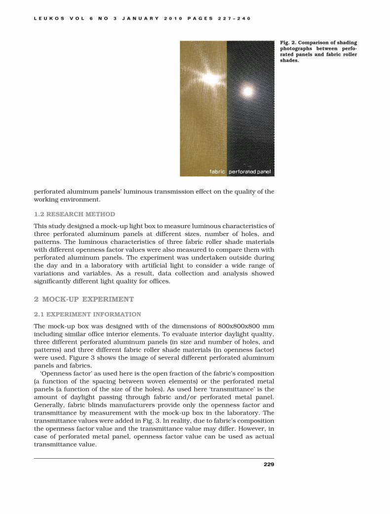
perforated aluminum panels’ luminous transmission effect on the quality of theworking environment.
1.2 RESEARCH METHOD
This study designed a mock-up light box to measure luminous characteristics ofthree perforated aluminum panels at different sizes, number of holes, andpatterns. The luminous characteristics of three fabric roller shade materialswith different openness factor values were also measured to compare them withperforated aluminum panels. The experiment was undertaken outside duringthe day and in a laboratory with artificial light to consider a wide range ofvariations and variables. As a result, data collection and analysis showedsignificantly different light quality for offices.
2 MOCK-UP EXPERIMENT
2.1 EXPERIMENT INFORMATION
The mock-up box was designed with of the dimensions of 800x800x800 mmincluding similar office interior elements. To evaluate interior daylight quality,three different perforated aluminum panels (in size and number of holes, andpatterns) and three different fabric roller shade materials (in openness factor)were used. Figure 3 shows the image of several different perforated aluminumpanels and fabrics.
‘Openness factor’ as used here is the open fraction of the fabric’s composition(a function of the spacing between woven elements) or the perforated metalpanels (a function of the size of the holes). As used here ‘transmittance’ is theamount of daylight passing through fabric and/or perforated metal panel.Generally, fabric blinds manufacturers provide only the openness factor andtransmittance by measurement with the mock-up box in the laboratory. Thetransmittance values were added in Fig. 3. In reality, due to fabric’s compositionthe openness factor value and the transmittance value may differ. However, incase of perforated metal panel, openness factor value can be used as actualtransmittance value.
Fig. 2. Comparison of shadingphotographs between perfo-rated panels and fabric rollershades.
L E U K O S V O L 6 N O 3 J A N U A R Y 2 0 1 0 P A G E S 2 2 7 – 2 4 0
229

To measure three different luminance values (A, B and C), a luminance meterwas installed at the back of the mock-box and measured through a pip-hole.Three different luminance values imply different viewing angles from inside tooutside according to the different inner locations and heights of people (either atchair or stand). To measure the illuminance value, the bottom of the mock-upbox was sectioned into three areas and measured at two points: A (1/3 depth)and B (2/3 depth). Figure 4 shows the outline of the mock-up experiment inlaboratory and outside.
In the case of the daylight experiment, both a clear sky with sunlight and anovercast sky without sunlight were tested. During the clear sky, two differentsunlight incident angles were tested. The mock-up box was laid on the ground fora common solar altitude situation, whereas the mock-up box’s angle was tilted toget the sunlight to be incident on a vertical glazing in a zero angle (see Fig. 5).
Fig. 3. Image of different per-forated aluminum panels andfabrics.
Fig. 4. Mock-up experiment.
L E U K O S V O L 6 N O 3 J A N U A R Y 2 0 1 0 P A G E S 2 2 7 – 2 4 0
230

Fig. 5. Image of the outsideexperiment.
L E U K O S V O L 6 N O 3 J A N U A R Y 2 0 1 0 P A G E S 2 2 7 – 2 4 0
231

In the laboratory experiment, an artificial light was projected with a narrowbeam angle to obtain a similar sunlight condition. It was tested with two differentsunlight incident angles as in the case of daylighting experiment. In addition,another artificial light with a wider beam angle was used. This artificial lightequipment was projected in the opposite direction of the mock-up box to reflecta sky condition (see Fig. 6).
2.2 EXPERIMENT WITH ARTIFICIAL LIGHTING
2.2.1 LUMINANCE MEASUREMENT
Three different luminance values (MA, MB, and MC) were measured by artificiallighting at different viewing angles from inside to outside based on different innerlocations and heights of individuals. To mimic similar direct sunlight conditions,artificial light was shined on the front of the mock-up box. Also, to simulate a sky(indirect condition), a screen was installed to reflect artificial light onto themock-up box. Table 1 shows the luminous values with its different lightingmethods and incident angles of direct sun: direct (0 degree incident angle) �indirect, direct (higher incident angle) � indirect, and indirect.
2.2.2 ILLUMINANCE MEASUREMENT
The illuminance values were measured at two different points: sensor 1 andsensor 2. Table 2 presents horizontal illuminance values at two different points,and the artificial light configuration was the same as the luminance measure-ment above. In addition, a vertical illuminance outside of the perforated panelsand fabrics was measured to compare values and inside horizontal illuminancevalues.
2.3 EXPERIMENT IN DAYLIGHT
2.3.1 LUMINANCE MEASUREMENT
Luminance values of a perforated panel and fabric roller shade were measuredfrom inside the mock up box facing the artificial light outside. Also, illuminancevalues were measured at two different points inside of the mock up box. Toobtain objective measurement values, an additional experiment was conductedoutside the mock up box under daylight with the same experimental conditions.Table 3 shows the luminous values under different lighting methods andincident angles of direct sun as with the measurement of artificial light.
Due to the luminance meter’s acceptance angle (1/3°), individual hole of aperforated panel was not able to be measured. Thus, luminance values differedfrom the perforated panel’s openness factors and patterns. During daylight,luminance values were sometimes not obtained because it was occasionally outof the possible evaluation range (0.001 – 999,900 cd/m2).
2.3.2 ILLUMINANCE MEASUREMENT
The illuminance values were also measured at identical points with the samemethod as with the measurement with artificial light. Table 4 presents theseresults.
L E U K O S V O L 6 N O 3 J A N U A R Y 2 0 1 0 P A G E S 2 2 7 – 2 4 0
232
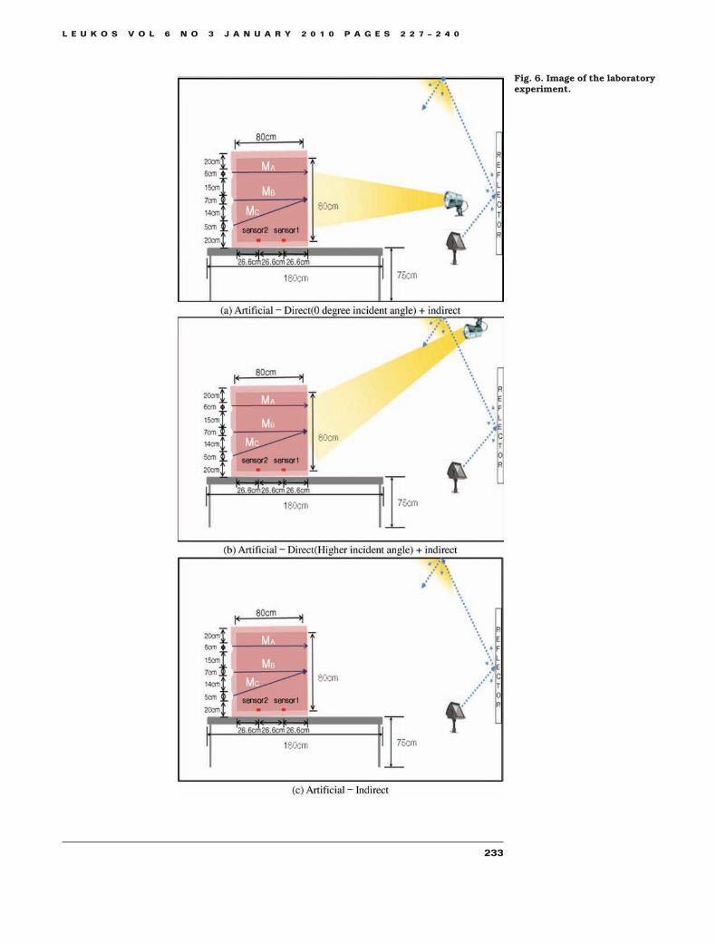
Fig. 6. Image of the laboratoryexperiment.
L E U K O S V O L 6 N O 3 J A N U A R Y 2 0 1 0 P A G E S 2 2 7 – 2 4 0
233

TABLE 1.Luminance MeasurementWith Artificial Lighting(Unit: cd/m2)
Artificial—Direct (0 degree incident angle) � indirect
Perforated Panels Fabrics
2mm (OpennessFactor 5.02%)
3mm (OpennessFactor 9.04%)
2mm (OpennessFactor 14.51%)
OpennessFactor 1%
OpennessFactor 3%
OpennessFactor 6%
MA 43.52 78.68 115.9 48.86 56.33 92.68
MB 21920 43610 57430 5488 9674 26710
MC 24450 44210 67320 5812 9738 29670
Artificial—Direct (Higher incident angle) � indirect
Perforated Panels Fabrics
2mm (OpennessFactor 5.02%)
3mm (OpennessFactor 9.04%)
2mm (OpennessFactor 14.51%)
OpennessFactor 1%
OpennessFactor 3%
OpennessFactor 6%
MA 2.54 5.07 9.88 43.49 53.24 68.65
MB 3.54 6.37 13.5 39.93 48.41 63.49
MC 2.24 4.46 7.31 39.78 48.4 62.3
Artificial—Indirect
Perforated Panels Fabrics
2mm (OpennessFactor 5.02%)
3mm (OpennessFactor 9.04%)
2mm (OpennessFactor 14.51%)
OpennessFactor 1%
OpennessFactor 3%
OpennessFactor 6%
MA 65.44 208.9 300.9 68.82 79.45 158.7
MB 106.6 234.2 368 67.32 89.12 194
MC 121.8 238.4 384.1 55.04 87.03 190.1
TABLE 2.Illuminance MeasurementWith Artificial Lighting(Unit: lx)
Artificial—Direct (0 degree incident angle) � indirect
Perforated Panels Fabrics
2mm(Openness
Factor 5.02%)
3mm(Openness
Factor 9.04%)
2mm(Openness
Factor 14.51%)
OpennessFactor 1%
OpennessFactor 3%
OpennessFactor 6%
Ev. 902
Sensor1 10.46 22.49 35.3 36.9 47.1 66.2
Sensor2 13.21 27.86 44.5 32.3 41.6 61.8
Artificial—Direct (Higher incident angle) � indirect
Perforated Panels Fabrics
2mm(Openness
Factor 5.02%)
3mm(Openness
Factor 9.04%)
2mm(Openness
Factor 14.51%)
OpennessFactor 1%
OpennessFactor 3%
OpennessFactor 6%
Ev. 1271
Sensor1 8.51 32.4 27.91 47.9 60.6 95.8
Sensor2 6.74 16.27 20.92 37.5 47 66.6
Artificial—Indirect
Perforated Panels Fabrics
2mm(Openness
Factor 5.02%)
3mm(Openness
Factor 9.04%)
2mm(Openness
Factor 14.51%)
OpennessFactor 1%
OpennessFactor 3%
OpennessFactor 6%
Ev. 953
Sensor1 9.45 22.31 31.2 39 48.9 69.5
Sensor2 10.88 24.8 35.4 34.3 43.7 63.9
L E U K O S V O L 6 N O 3 J A N U A R Y 2 0 1 0 P A G E S 2 2 7 – 2 4 0
234

TABLE 3.Luminance MeasurementWith Daylight (Unit: cd/m2)
Clear Sky With the Sunlight (Tilted)
Perforated Panels Fabrics
2mm (OpennessFactor 5.02%)
3mm (OpennessFactor 9.04%)
2mm (OpennessFactor 14.51%)
OpennessFactor 1%
OpennessFactor 3%
OpennessFactor 6%
MA 8042 11410 30040 12480 15630 17250
MB 9718 25300 3410 22400 64890 94490
MC 9288 17830 32460 19020 61450 92170
Clear Sky With the Sunlight
Perforated Panels Fabrics
2mm (OpennessFactor 5.02%)
3mm (OpennessFactor 9.04%)
2mm (OpennessFactor 14.51%)
OpennessFactor 1%
OpennessFactor 3%
OpennessFactor 6%
MA 64.1 164 339 1428 1622 2213
MB 88.6 253 391 1350 1594 2036
MC 104.3 282 393 1327 1496 1903
Overcast Sky Without the Sunlight
Perforated Panels Fabrics
2mm (OpennessFactor 5.02%)
3mm (OpennessFactor 9.04%)
2mm (OpennessFactor 14.51%)
OpennessFactor 1%
OpennessFactor 3%
OpennessFactor 6%
MA 846.2 1670 3083 1732 2369 3430
MB 1005 1876 3156 1777 2365 3401
MC 943.7 1902 3046 1953 2348 3351
TABLE 4.Illuminance MeasurementWith Daylight (Unit: lx)
Clear Sky With the Sunlight (Tilted)
Perforated Panels Fabrics
2mm (OpennessFactor 5.02%)
3mm (OpennessFactor 9.04%)
2mm (OpennessFactor 14.51%)
OpennessFactor 1%
OpennessFactor 3%
OpennessFactor 6%
Ev. 44800 45400 41500 42000 45300 44100
1 480 1047 1542 1655 2254 3140
2 568 1231 1761 1385 1902 2760
Clear Sky With the Sunlight
Perforated Panels Fabrics
2mm (OpennessFactor 5.02%)
3mm (OpennessFactor 9.04%)
2mm (OpennessFactor 14.51%)
OpennessFactor 1%
OpennessFactor 3%
OpennessFactor 6%
Ev. 31900 28000 29000 33500 38100 37200
1 615 1125 1450 1345 2067 3160
2 515 1049 1300 1158 1836 2960
Overcast Sky Without the Sunlight
Perforated Panels Fabrics
2mm (OpennessFactor 5.02%)
3mm (OpennessFactor 9.04%)
2mm (OpennessFactor 14.51%)
OpennessFactor 1%
OpennessFactor 3%
OpennessFactor 6%
Ev. 54200 53800 50700 48100 48500 50600
1 284 512 1800 2048 2650 1332
2 516 1186 1567 1493 1898 2690
L E U K O S V O L 6 N O 3 J A N U A R Y 2 0 1 0 P A G E S 2 2 7 – 2 4 0
235

3 DISCUSSION
3.1 SHADING EFFECT
The mock-up box’s inside illuminance values in both artificial light and daylightshowed that perforated panels were more effective in blocking lights than fabricroller shades. Two different types of perforated panels blocked more daylightthan the fabric roller shades with 1% openness factor. The interpretation of thisresult can be discussed based on the following assumptions. Perforated panelsin daylight or artificial light can only transmit through holes of a perforatedpanel, but in case of fabric roller shades, even if the openness factor rate is low,it is less effective than a perforated panel because the fabric itself diffuses light.Consequently, the illuminance comparisons between perforated panels andfabric panels can be summarized as follows. In the case of illuminance values,irrespective of openness factor rates, fabric panels showed higher illuminancevalues than perforated panels. This is because of the fabric’s light diffusingcharacteristics and the fact that perforated panels are opaque and reflective anddo not transmit diffuse light. Figures 7 and 8 show relative illuminance valuescompared to those of fabric at 3 percent. These are the average values of the twomeasuring points.
Fig. 7. Relative illuminancevalue (0 degree incident angle).
Fig. 8. Relative illuminancevalue (higher degree incidentangle).
L E U K O S V O L 6 N O 3 J A N U A R Y 2 0 1 0 P A G E S 2 2 7 – 2 4 0
236

In the case of artificial lighting with incoming light with 0 degree incidentangle, perforated panel’s values MA, MB, and MC were higher. On the other hand,in case of daylighting with the same setting, except the MA value, fabric blindsshowed generally higher values. Moreover, all the MA, MB, and MC values werehigher with general sunlight altitude angles. These differences can be explainedwith the circumstances of luminance measurement condition and the relativedistance between measurement points and sunlight/artificial light source. It isso because when measuring luminance values, fabric blinds showed relativelyuniformed luminance values within the measured diameter, but perforatedpanels are composed of holes and metal surface and therefore, it showedirregular values depending on the measured part whether includes more holesor more solid surface. (See Fig. 9) To avoid this kind of error, this experimentused 1/3 degree luminance meter and Table 5 shows the measured luminancevalues on each condition. Due to the small distance between artificial lightsource and the perforated panel’s holes, which is the measurement point in thisexperiment, higher luminance values can be generated.
3.2 SIZE AND NUMBER OF PERFORATED HOLES IN ALUMINUM PANELS
The amount of incoming light and angle may be different based on the orienta-tion of a certain building. However, the result of this experiment showed that theuse of perforated panels as a shading device is possible in all conditions and theappropriate hole size of a perforated panel should be 2 mm to ensure viewing andsun blockage at the same time. If the hole size is larger than 3 mm, it mayproduce an uncomfortable glare at sunset and/or sunrise due to low sun anglesand/or of the position of a office worker.
On the other hand, it will possible to consider mix use of different hole sizes inone perforated panel to deliver outside views to the inside and direct sunlightblockage at the same time. More specifically, if we assume the general viewingheight is 1.5 m, the hole size of 3 mm 9 percent can be used under 1.5 m and holesize of 2 mm 5 percent can be used upper 1.5 m to allow effective sun block withthe maximum view assurance. For this mixed-use idea, it will be necessary toexamine individual’s visual confusion with a full scale mock-up model.
Fig. 9. Measurement of lumi-nance values of perforatedpanels and fabric roller shade.
L E U K O S V O L 6 N O 3 J A N U A R Y 2 0 1 0 P A G E S 2 2 7 – 2 4 0
237
3.3 COLOR OF ALUMINUM PANELS
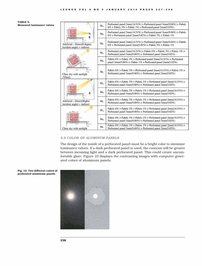
The design of the inside of a perforated panel must be a bright color to minimizeluminance values. If a dark perforated panel is used, the contrast will be greaterbetween incoming light and a dark perforated panel. This could create uncom-fortable glare. Figure 10 displays the contrasting images with computer gener-ated colors of aluminum panels.
TABLE 5.Measured luminance values
Fig. 10. Two different colors ofperforated aluminum panels.
L E U K O S V O L 6 N O 3 J A N U A R Y 2 0 1 0 P A G E S 2 2 7 – 2 4 0
238

On the other hand, if a perforated panel is designed with a bright color or withspecular texture that can generate a mirror effect for the outside, then it has thepotential to produce a disturbing glare toward surrounding buildings. Therefore,this was considered and we used two different colors (white and light green) foreach surfaces of the tested perforated panels and, since the vertical perforatedpanels can be rotated 180 degree, either white or light green perforated panelscan be seen from the outside and/or inside of a building. (See Fig. 11) To avoidany disturbing glare, both sides of the perforated panels have nonspecular mattesurface rather then glossy texture.
CONCLUSION
This study compared perforated panels (openness factor of 5 percent, 9 percent,and 15 percent) and fabric roller shades (openness factor of 1 percent, 3 percent,and 6 percent) to obtain quantitative values of perforated panel’s sun blockingeffects. Also, this experiment was conducted with both artificial light anddaylight to verify perforated panel’s shading effects under a wide range ofshading variables.
According to the mock-up test results with artificial light and daylight,perforated panels with openness factors of 5 percent and 9 percent were moreeffective in blocking sunlight than general fabric roller shades based on interiorilluminance values. With the exception of certain cases, most of the perforatedpanels showed lower luminance values than general fabric roller shades whileviewing inside and outside. This is because fabric roller shades, even with lowtransmitting rates, diffuse light while perforated panels allow light only throughhole openings. Consequently, fabric panels diffuse daylight, which could be anadvantage for a work environment, but they require high maintenance becauseof discolorations or fading of the fabric, which will not appear in perforatedpanels. When daylight shines directly through perforated panels, the luminancerate becomes excessive. Despite this negative point, perforated panels can beconsidered a valuable shading devices since they can deliver outside to insideviews through hole openings. Furthermore, to make a perforated panel amore suitable shading device, it is necessary to design the inside of aperforated panel with a bright color to minimize glaring. The surface of aperforated panel that faces outside should absorb sunlight as little as
Fig. 11. Real perforated alumi-num panels- electro-motor-ized vertical blind.
L E U K O S V O L 6 N O 3 J A N U A R Y 2 0 1 0 P A G E S 2 2 7 – 2 4 0
239

possible and, therefore, should avoid dark color. Simultaneously, it shouldminimize reflecting glare and, therefore, the texture of the surface should bedesigned with a nonspecular texture.
Throughout this study, a perforated panels with known openness factors andpatterns proved to be a potentially excellent shading device. To maximize itseffect, a mix use of different hole sizes with various opening rates are recom-mended to effectively deliver outside views while functioning as a shading device.More specifically, a hole size of 3 mm (openness factor of 9 percent) can beapplied for the lower part and a hole size of 2 mm (openness factor of 5 percent)can be used for the upper part according to human height. If manufacturingperforated panels that combines two or more different openness factors is notpractically possible, then a conservative approach, low openness factor such as5 percent, can be recommended to prevent excessive luminances. For furtherresearch, it will be necessary to examine office workers visual comfort as forqualitative aspects of luminous environments with a full scale mock-up test.This should be measured and experimented in an actual office space and actualoffice worker’s qualitative analysis should be an important check point.
REFERENCES
Aghemo C, Pellegrino A, Loverso VRM. 2008. The approach to daylighting by scale modelsand sun and sky simulators: A case study for different shading systems. Build Environ.43(5):917–927.
Kim YS, Park BC, Jeong KY, Choi AS, Lee JH. 2007. A comparison of daylight distributionfrom different height of roller shade and venetian blind. Architectural institute Korea. 24(1):1001–1004.
Park BC, Kim YS, Jeong KY, Choi AS, Lee JH. 2007. Analyzing daylight distribution andevaluating discomfort glare of roller shade and venetian blind using the RADIANCE software.Architectural institute Korea. 24(1):993–996.
Wittkopf SK. 2008. Daylight performance of anidolic ceiling under different sky conditions.Solar Energy. 81(2):199–211.
L E U K O S V O L 6 N O 3 J A N U A R Y 2 0 1 0 P A G E S 2 2 7 – 2 4 0
240