lycoming aircraft engines parts catalog & tvo-435...part no. pc-110 652 oliver street...
TRANSCRIPT

Part No. PC-110652 Oliver Street
Williamsport, PA 17701
VO-435 and TVO-435 SeriesHelicopter Engines
Lycoming Aircraft EnginesParts Catalog


SUPPLEMENTAL PARTS LIST NO. SSP3071-1
TO PROVIDE OIL LEVEL GAGE TO PARTS LIST SUPPLEMENT NO. SSP3071
LYCOMING TVO-435-F1A AIRCRAFT ENGINES
This information is being issued to provide an additional part not covered inthe original publication SSP3071. The oil level gage (sight gage), at the presenttime is being used on TVO-435-F1A model engines only. Lycoming PartsCatalog involved is PC-110.
PART NO. NAME QTY. PER ASS'Y. ENGINE MODEL
LW-12066 Gage, Oil Level 1 TVO-435-F1A(Sight Gage)


SUPPLEMENTAL PARTS LIST NO. SSP3071
TO PROVIDE COVERAGE FOR LYCOMING MODEL
TVO-435-B1A,-D1A,-D1B,-F1A AND -G1A
AIRCRAFT ENGINES
This supplement is arranged in the same basic format as the original catalog, Lycoming, PC-110.It will serve to update published information on the following models: TVO-435-B1A,-D1A and -G1A. Itwill also add parts coverage on two additional models, TVO-435-D1B and -F1A.
Page numbers listed in this supplement conform to basic page numbers in the original catalog. Figurereference numbers also conform to those parts breakdown illustrations contained in PC-110. Where afigure reference number is left blank in this supplement, it denotes a new part or that no referencenumber was assigned in the original catalog. If a page in the original catalog does not apply to subjectengines, it is so designated in this supplement. SSP1168 supplement is replaced by SSP3071.
1
SSP3071 PC-110 January 1972
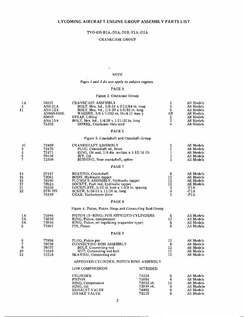
LYCOMING AIRCRAFT ENGINE GROUP ASSEMBLY PARTS LIST
1A4
11
76227AN6-21AAN4-12AAN960-616L60803AN4-15A75302
TVO-435-B1A,-D1A,-D1B,-F1A,-G1A
CRANKCASE GROUP
NOTE
Pages 1 and 2 do not apply to subject engines.
PAGE 3
Figure 2. Crankcase Group
CRANKCASE ASSEMBLYBOLT, Hex. hd., 3/8-24 x 2-13/64 in. longBOLT, Hex. hd., 1/4-20 x 1-9/32 in. longWASHER, 3/8 x 0.032 in. thick (1 max.)
STRAP, LiftingBOLT, Hex. hd., 1/4-28 x 1-21/32 in. long
DOWEL, Crankcase thru stud
PAGE 5
Figure 3. Crankshaft and Camshaft Group
CRANKSHAFT ASSEMBLYPLUG, Crankshaft oil, frontRING, Oil seal, 1/8 dia. section x 1-13/16 IDJET, OilBUSHING, Rear crankshaft, spline
PAGE 7
BEARING, CrankshaftBODY, Hydraulic tappetPLUNGER ASSEMBLY, Hydraulic tappetSOCKET, Push rod, hydraulic tappetLOCKPLATE, 5/16 in. bolt x 1-3/8 in. spacingSCREW, 5/16-24 x 11/16 in. longGEAR, Tachometer drive
PAGE 8
1 All Models4 All Models5 All Models
AR All Models2 All Models2 All Models4 All Models
1C3457
7246972470724717043472308
1 All Models1 All Models1 All Models1 All Models1 All Models
141516172122
6744773061782907852476332STD-70776319
8 All Models12 All Models12 All Models12 All Models
2 -F1A4 -F1A1 -F1A
1A2A3A5
75984739337393477857
Figure 4. Piston, Piston Rings and Connecting Rod Group
PISTON (3-RING) FOR NITRIDED CYLINDERSRING, Piston, compressionRING, Piston, oil regulating (expander type)PIN, Piston
PAGE 9
6 All Models12 All Models
6 All Models6 All Models
679
1012
7785678028780277464672218
PLUG, Piston pinCONNECTING ROD ASSEMBLY
BOLT, Connecting rodNUT, Connecting rod bolt
BEARING, Connecting rod
APPROVED CYLINDER, PISTON RING ASSEMBLY
12 All Models6 All Models
12 All Models12 All Models12 All Models
LOW COMPRESSION NITRIDED
CYLINDERPISTONRING, CompressionRING, OilEXHAUST VALVEINTAKE VALVE
742187598473933 ch.73934 ch.7480273129
6 All Models6 All Models
12 All Models6 All Models.6 All Models6 All Models
2

LYCOMING AIRCRAFT ENGINE GROUP ASSEMBLY PARTS LIST
TVO-435-B1A,-D1A,-D1B,-F1A,-G1A
CYLINDER GROUP
PAGE 11
Figure 5. Cylinder Group
NUT, Plain, 1/2 -20
NOTE
Figure reference numbers 3 and 5 no longer apply.
SEAT, Intake valve
PAGE 13
2 STD-2090 24 All Models
6 71895 6 All Models
79
7189475838
SEAT, Exhaust valveGUIDE, Valve exhaust
6 All Models6 All Models
NOTE
Figure reference numbers 14 and 16 do not apply to subject engines.
PAGE 14
2122
2425
262731
748026832573112LW-11797LW-10077LW-10076MS13997-3MS13998-372626
VALVE, Exhaust, rotator typeSEAT, Valve spring, lowerSEAT, Valve spring, lowerSPRING, Valve, auxiliarySEAT, Valve springSEAT, Valve spring (rotator type)KEY, Valve, rotator typeCAP, Valve stemSHAFT, Valve rocker
PAGE 15
6 All Models6 All Models6 All Models
12 All Models6 All Models6 All Models
12 All Models6 All Models
12 All Models
3640
74388STD-1925STD-1925STD-18747449479051LW-11964734347343573436
ROCKER ASSEMBLY, Exhaust valveSCREW, Pan-head, self-locking,1/4-20 x 5/8 longSCREW, Pan-head, self-locking,1/4-20 x 5/8 longSCREW, Fill. hd., self-locking, 1/4-20 x 15/16 longPLATE, Spark plug cautionSPRING, Shroud tubeSEAL, Shroud tube, crankcase endROD ASSEMBLY, PushROD ASSEMBLY, PushROD ASSEMBLY, Push
64847
16
1212ARARAR
All Models-B1A,-D1A,-D1B,-G1A-F1A-F1AAll ModelsAll ModelsAll ModelsAll ModelsAll ModelsAll Models
424547
PAGE 16
Figure 6. Induction System Group
NOTE
Pages 16, 17 and 18 do not apply to subject engines.
PAGE 19
1
234
77667LW-12025STD-8STD-160STD-9
Figure 7. Induction System Group
COVER ASSEMBLY, CrankcaseCOVER ASSEMBLY, CrankcaseWASHER, Plain, 1/4 in.WASHER, Internal lock, 1/4 in.NUT, Plain, 1/4-28
3
1 -B1A,-D1A,-D1B,-G1A1 -F1A
28 All Models18 All Models
9 All Models

LYCOMING AIRCRAFT ENGINE GROUP ASSEMBLY PARTS LIST
TVO-435-B1A,-D1A,-D1B,-F1A,-G1A
INDUCTION SYSTEM GROUP (CONT.)
56
15161718
STD-1679STD-1230AN4-12A7674077669STD-82STD-42577668LW-12001STD-1922STD-1921AN6289-D16LW-10126AN816-1673346
BOLT, Hex. hd., 1/4-28 x 1.00 in. longBOLT, Hex. hd., 1/4-28 x 1-9/32 in. longBOLT, Long hd., 1/4-28 x 1-9/32 in. longGASKET OIL SUMPBAFFLE, BreatherSCREW, Fill. hd., drilled, No. 10-24 x 1/2 in. longWASHER, Plain, No. 10GASKET, Breather baffleADAPTER ASSEMBLY, Oil fillerRING, Oil seal, 1-11/64 ID x 0.116 sectionRING, Back-up, 1.172 ID x 1.514 OD x 1/8 thickNUT, Flared tube, universal fitting 1-5/16-12CAP, Oil fillerNIPPLE, 1.00 in. flared tube, 1.00 in. NPTFLANGE, Intake pipe upper
PAGE 21
9 All Models9 -F1A9 -B1A,-D1A,-D1B,-G1A1 -B1A,-D1A,-D1B,-G1A1 All Models
18 All Models14 All Models
1 All Models1 -F1A1 -F1A1 -F1A1 -F1A1 -F1A1 -F1A6 All Models20
232428B34
STD-121571973738997334777304
1D
6
7
70406LW-12027STD-1339STD-133967742763397600175757763337633575162
BOLT, Hex. hd., 1/4-20 x 1-1/4 in. longGASKET, Two bolt flange, 1-7/8 in. IDCARBURETOR ASSEMBLY, MA-6AAADAPTER, Carburetor inletADAPTER, Carburetor inlet
PAGE 22
Figure 8. Accessory Housing Group
HOUSING ASSEMBLY, AccessoryHOUSING ASSEMBLY, Accessory
PLUG, Allen hd., 1/16-27 pipePLUG, Allen hd., 1/16-27 pipeBUSHING, 1-7/8 OD x 1-11/16 ID x 3/4 in. longBUSHING, 1-1/32 OD x 7/8 ID x 29/32 in. longBUSHING, 1-3/32 OD x 1.00 ID x 1-3/8 in. longBUSHING, 1-5/8 OD x 1-7/16 ID x 1-1/4 in.longBUSHING, 2-3/16 OD x 2.00 ID x 1-3/16 in. longBUSHING, 1-9/16 OD x 1-3/8 ID x 15/16 in. longBUSHING, 15/32 OD x 13/32 ID x 5/8 in. long
NOTE
12 All Models6 All Models1 All Models1 -B1A1 -D1A,-D1B,-F1A,-G1A
1 -B1A,-D1A,-D1B,-G1A1 -F1A5 -B1A,-D1A,-D1B,-G1A4 -F1A1 -B1A,-D1A,-D1B,-G1A1 -F1A1 -F1A1 -F1A1 -F1A1 -F1A1 -F1A
Figure reference number 8 does not apply to subject engines.
PAGE 23
9
12
14
16
STD-859STD-39466145STD-103725-1225-1225-1325-13STD-1003STD-1353STD-116425-1125-2831-1631-1731-1331-14
DOWEL, 1/8 in. dia. x 9/32 in. longDOWEL, 3/32 in. dia. x 11/32 in. longDOWEL, 1/4 in. dia. x 1/2 in. longDOWEL, 3/16 in. dia. x 1/4 in. longSTUD, 1/4-20 x 1-1/2 in. longSTUD, 1/4-20 x 1-1/2 in. longSTUD, 1/4-20 x 1-5/8 in. longSTUD, 1/4-20 x 1-5/8 in. longDOWEL, Oil, 1/4 OD x 3/16 ID x 1/2 in. longINSERT, Heli-coil, No. 10-24 x 3/8 in. longINSERT, Heli-coil, 5/16-18 x 5/8 in. longSTUD, 1/4-20 x 1-3/8 in. longSTUD, 1/4-20 x 3-1/2 in. longSTUD, 5/16-18 x 2.00 in. longSTUD, 5/16-18 x 2-1/8 in. longSTUD, 5/16-18 x 1-5/8 in. longSTUD, 5/16-18 x 1-3/4 in. long
4
1 -B1A,-D1A,-D1B,-G1A6 -F1A2 -B1A,-D1A,-D1B,-G1A1 -F1A
11 -B1A,-D1A,-D1B,-G1A9 -F1A
17 -B1A,-D11A,-D1B,-G1A3 -F1A1 -F1A4 -F1A1 -F1A6 -F1A2 -F1A1 -F1A3 -F1A8 -F1A4 -F1A

LYCOMING AIRCRAFT ENGINE GROUP ASSEMBLY PARTS LIST
TVO-435-B1A,-D1A,-D1B,-F1A,-G1A
ACCESSORY HOUSING GROUP (CONT.)
25-10 STUD, 1/4-20 x 1-1/4 in. long25-13 STUD, 1/4-20 x 1-5/8 in. long25-33 STUD, 1/4-20 x 4-1/8 in. long
29 69637 PLUG, 3/4 in. dia. x 9/16 in. long33 1102 PLUG, Allen hd., 1/8-27 NPT
1102 PLUG, Allen hd., 1/8-27 NPT34 STD-71 PLUG, Allen hd., 3/8 pipe
STD-784 PLUG, Allen hd., 3/8-18 pipe36 69636 TUBE AND STRAINER ASSEMBLY, Oil suction
76307 TUBE ASSEMBLY, Oil suction37 STD-111 GASKET, 1.00 ID x 1-1/4 OD x 3/32 annular
76340 GASKET, Oil suction tube42 AN816-4-4 NIPPLE, Flared tube and pipe thd.
AN912-3D BUSHING REDUCER, 3/8 to 1/8 in. pipe thd.STD-1431 SCREW, Hex. hd., drilled hd., 1/4-28 x 7/8 in. longAN825-4 TEE, 1/4 flared tube to 1/8 NPT. 90 (oil to turbo-
charger)78171 ELBOW, Turbocharger oil drain connection
NOTE
Figure reference numbers 11, 29, 38 and 39 do not apply to TVO-435-F1A model engines.does not apply to any of the subject engines.
PAGE 25
NOTE
333113211111112
11
-F1A-F1A-F1A-B1A,-D1A,-D1B,-G1A-B1A,-D1A,-D1B,-G1A-F1A-B1A,-D1A,-D1B,-G1A-F1A-B1A,-D1A,-D1B,-G1A-F1AAll Models-F1A-D1A,-D1B,-G1A-F1A-F1A
-F1A-F1A
Figure reference number 44
Figure 8 reference numbers 45, 46, 47 and 48 do not apply to subject engines.
Figure 9. Accessory Drives Group
NOTE
Figure references 1 thru 21, apply to TVO-435-BIA,A,-D1,-D1B,-GIA model engines only.
1216
763377605776334STD-1976016STD-160STD-976336MS16624-377627976300
SHAFT, Magneto drive idlerGEAR ASSEMBLY, Magneto drive idler
BUSHING, 3/8 ID x 7/16 OD x 7/8 in. longDOWEL, 3/32 in. dia. x 7/32 in. long
RING, Oil seal, 0.49 ID x 5/64 in. sectionWASHER, Internal lock, 1/4 in.NUT, Plain, 1/4-28WASHER, Thrust, magneto idler shaftRING, External retaining, 1-3/8 in. dia. shaftGEAR, MagnetoWASHER, Magneto drive shaft gear
PAGE 27
1 -F1A1 -F1A1 -F1A1 -F1A1 -F1A1 -F1A1 -F1A1 -F1A2 -F1A1 -F1A1 -F1A
31 AN115907 SCREW, Fill. hd., drilled, 1/4-28 x 1/2 in. long
NOTE
6 -B1A,-D1A,-D1B,-G1A
Figure reference numbers 22 thru 48 apply to TVO-435-B1A,-D1A,-DIB,-GIA model engines only.
LW-12023767757681676815STD-8STD-160STD-1411
STARTER MOTOR ASSEMBLY (24-Volt)SWITCH, Magnetic (Prestolite SAW-4411)PLATE, Starter retainingSTUD, Starter retaining plateWASHER, Plain, 1/4 in.WASHER, Internal lock, 1/4 in.NUT, Plain, 1/4-20
5
1 -F1A1 -F1A1 -F1A2 -F1A
14 -F1A12 -F1A4 -F1A
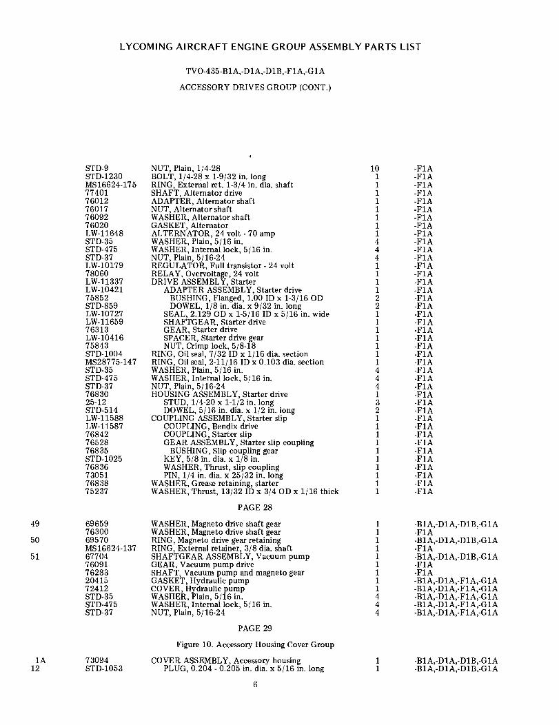
LYCOMING AIRCRAFT ENGINE GROUP ASSEMBLY PARTS LIST
TVO-435-B1A,-D1A,-D1B,-F1A,-G1A
ACCESSORY DRIVES GROUP (CONT.)
STD-9STD-1230MS16624-1757740176012760177609276020LW-11648STD-35STD-475STD-37LW-1017978060LW-11337LW-1042175852STD-859LW-10727LW-1165976313LW-1041675843STD-1004MS28775-147STD-35STD-475STD-377683025-12STD-514LW-11588LW-11587768427652876835STD-102576836730517683875237
NUT, Plain, 1/4-28BOLT, 1/4-28 x 1-9/32 in. longRING, External ret. 1-3/4 in. dia. shaftSHAFT, Alternator driveADAPTER, Alternator shaftNUT, Alternator shaftWASHER, Alternator shaftGASKET, AlternatorALTERNATOR, 24 volt - 70 ampWASHER, Plain, 5/16 in.WASHER, Internal lock, 5/16 in.NUT, Plain, 5/16-24REGULATOR, Full transistor - 24 voltRELAY, Overvoltage, 24 voltDRIVE ASSEMBLY, Starter
ADAPTER ASSEMBLY, Starter driveBUSHING, Flanged, 1.00 ID x 1-3/16 ODDOWEL, 1/8 in. dia. x 9/32 in. long
SEAL, 2.129 OD x 1-5/16 ID x 5/16 in. wideSHAFTGEAR, Starter driveGEAR, Starter driveSPACER, Starter drive gearNUT, Crimp lock, 5/8-18
RING, Oil seal, 7/32 ID x 1/16 dia. sectionRING, Oil seal, 2-11/16 ID x 0.103 dia. sectionWASHER, Plain, 5/16 in.WASHER, Internal lock, 5/16 in.NUT, Plain, 5/16-24HOUSING ASSEMBLY, Starter drive
STUD, 1/4-20 x 1-1/2 in. longDOWEL, 5/16 in. dia. x 1/2 in. long
COUPLING ASSEMBLY, Starter slipCOUPLING, Bendix driveCOUPLING, Starter slipGEAR ASSEMBLY, Starter slip coupling
BUSHING, Slip coupling gearKEY, 5/8 in. dia. x 1/8 in.WASHER, Thrust, slip couplingPIN, 1/4 in. dia. x 25/32 in. long
WASHER, Grease retaining, starterWASHER, Thrust, 13/32 ID x 3/4 OD x 1/16 thick
PAGE 28
10 -F1A1 -F1A1 -F1A1 -F1A1 -F1A1 -F1A1 -F1A1 -F1A1 -F1A4 -F1A4 -F1A4 -F1A1 -F1A1 -F1A1 -F1A1 -F1A2 -F1A2 -F1A1 -F1A1 -F1A1 -F1A1 -F1A1 -F1A1 -F1A1 -F1A4 -F1A4 -F1A4 -F1A1 -F1A3 -F1A2 -F1A1 -F1A1 -F1A1 -F1A1 -F1A1 -F1A1 -F1A1 -F1A1 -F1A1 -F1A1 -F1A
49
50
51
696597630069570MS16624-1376770476091762832041572412STD-35STD-475STD-37
WASHER, Magneto drive shaft gearWASHER, Magneto drive shaft gearRING, Magneto drive gear retainingRING, External retainer, 3/8 dia. shaftSHAFTGEAR ASSEMBLY, Vacuum pumpGEAR, Vacuum pump driveSHAFT, Vacuum pump and magneto gearGASKET, Hydraulic pumpCOVER, Hydraulic pumpWASHER, Plain, 5/16 in.WASHER, Internal lock, 5/16 in.NUT, Plain, 5/16-24
PAGE 29
1 -B1A,-D1A,-D1B,-G1A1 -F1A1 -B1A,-D1A,-D1B,-G1A1 -F1A1 -B1A,-D1A,-D1B,-G1A1 -F1A1 -F1A1 -B1A,-D1A,-F1A,-G1A1 -B1A,-D1A,-F1A,-G1A4 -B1A,-D1A,-F1A,-G1A4 -B1A,-D1A,-F1A,-G1A4 -B1A,-D1A,-F1A,-G1A
1A12
73094STD-1053
Figure 10. Accessory Housing Cover Group
COVER ASSEMBLY, Accessory housingPLUG, 0.204 - 0.205 in. dia. x 5/16 in. long
6
1 -B1A,-D1A,-D1B,-G1A1 -B1A,-D1A,-D1B,-G1A

LYCOMING AIRCRAFT ENGINE GROUP ASSEMBLY PARTS LIST
TVO-435-B1A,-D1A,-D1B,-F1A,-G1A
ACCESSORY HOUSING COVER GROUP (CONT.)
23 74097 ELBOW, Int. and ext. pipe, 90 ° (assemble inaccy. hsg. cover side oil-out boss)
DUAL VACUUM PUMP AND FUEL PUMP DRIVE
1 -B1A,-D1A,-D1B,-G1A
8313LW-1201025-1231-3166145LW-120067159676466MS16625-56LW-12008LW-1201769731LW-1202171596LW-12019STD-1339STD-93869318STD-548STD-20825-1225-1631-14STD-8STD-160STD-9
GASKET, Vacuum pump driveADAPTER ASSEMBLY, Dual accessory drive
STUD, 1/4-20 x 1-1/2 in. longSTUD, 5/16-18 x 2-7/8 in. longDOWEL, 1/4-20 x 1/2 in. long
GEAR, Dual accessory driveWASHER, Accessory drive gearSHAFT, Quill, dual drive adapterRING, Internal retainingGASKET, Dual accessory drive adapter coverGEAR ASSEMBLY, Accessory idler
BUSHING, Accessory idler gearGEAR ASSEMBLY, Vacuum pump drivenWASHER, Accessory drive gearCOVER ASSEMBLY, Vacuum pump and fuel pump drive
PLUG, Allen head, 1/16 in -27 NPTDOWEL, 3/32 in. dia. x 11/32 in. longSHAFT, Accessory idler gearSEAL, Oil, 7/8 ID x 1-3/8 OD x 5/16 in. wideSEAL, Oil, 7/8 ID x 1-1/2 OD x 5/16 in. wideSTUD, 1/4-20 x 1-1/2 in. longSTUD, 1/4-20 x 2.00 in. longSTUD, 5/16-18 x 1-3/4 in. long
WASHER, Plain, 1/4 in.WASHER, Internal lock, 1/4 in.NUT, Plain, 1/4-28
PAGE 31
NOTE
1 -F1A1 -F1A1 -F1A3 -F1A2 -F1A1 -F1A1 -F1A1 -F1A1 -F1A1 -F1A1 -F1A1 -F1A1 -F1A1 -F1A1 -F1A1 -F1A1 -F1A1 -F1A1 -F1A1 -F1A1 -F1A1 -F1A1 -F1A6 -F1A6 -F1A6 -FIA
Figure reference numbers 25 thru 28 are employed as required. (See Page 33 for -FIA, Tach.Drive).
Figure 12. Oil Pump Group
1B 73091730897633873086
PUMP ASSEMBLY, OilPUMP ASSEMBLY, OilPUMP ASSEMBLY, Oil
BODY ASSEMBLY, Oil pressure pump
PAGE 33
1 -B1A,-D1A,-D1B,-G1A1 -B1A,-D1A,-G1A1 -F1A1 -B1A,-D1A,-D1A B,-G1A5
8
23
30
730887631725D-1131-1231-14STD-11647551575516STD-1973STD-208STD-13157631676315STD-3947626966145
BODY ASSEMBLY, Oil pressure pumpBODY ASSEMBLY, Oil pressure pump
STUD, Drilled end, 1/4-20 x 1-3/8 in. longSTUD, 5/16-18 x 1-1/2 in. longSTUD, 5/16-18 x 1-3/4 in. long'INSERT, Heli-coil, 5/16-18 x 5/8 in. longSHAFT, Oil pumpSHAFT, Oil pumpKEY, Woodruff, 1/8 in. x 3/4 in. dia.OIL SEAL, 7/8 in. ID x 1-1/2 OD x 5/16 in. wideINSERT, Heli-coil, 1/4-28 x 1/2 in. long
COVER ASSEMBLY, Oil pump bodyBUSHING, Oil pump drive shaftDOWEL, 0.0907 x 11/32 in. longSHAFT, Oil pump idlerDOWEL, 1/4 in. dia. x 1/2 in. long
7
1 -B1A,-D1A,-G1A1 -F1A4 -F1A1 -B1A,-D1A,-G1A3 -B1A,-D1A,-G1A1 -B1A,-D1A,-G1A1 -B1A,-D1A,-D1B,-G1A1 -B1A,-D1A,-G1A1 -B1A,-D1A,-D1B,-G1A1 -B1A,-D1A,-G1A2 -F1A1 -F1A1 -F1A1 -F1A1 -F1A2 -F1A

LYCOMING AIRCRAFT ENGINE GROUP ASSEMBLY PARTS LIST
TVO-435-B1A,-D1A,-D1B,-F1A,-G1A
OIL PUMP GROUP (CONT.)
AN381-4-22762676129768404STD-197376274STD-61STD-713STD-8STD-43STD-208
AN763-16LW-1202276015AN763-1678048STD-1353STD-425STD-251MS24677-26AN763-1676329STD-425STD-18967630876280STD-1973MS16624-59760477633076022760217631461165STD-8STD-160STD-961549
PIN, Cotter, 1/8 in. dia. x 1-3/8 in. longSHAFT, Hydraulic or oil pumpIMPELLER, Oil pressure pump drivingIMPELLER, Oil pressure pump drivenKEY, Woodruff, 1/8 in. x 3/4 in. dia.GEAR, Oil pressure pumpNUT, Slotted shear, 1/2-20PIN, Cotter, 3/32 in. dia. x 3/4 in. longWASHER, Plain, 1/4 in.NUT, Slotted shear, 1/4-28SEAL, Oil, 7/8 in. ID x 1-1/2 in. OD x 5/16
in. wideGASKET, Oil pump outlet flangeFLANGE, Oil pump outletRING, Oil seal, 35/64 in. ID x 5/64 in. sectionGASKET, Oil pump outlet flangeADAPTER ASSEMBLY, Oil pump outlet
INSERT, Heli-coil, No. 10-24 x 3/8 in. longWASHER, Plain, No. 10-24WASHER, Internal lock, No. 10-24SCREW, Socket head, No. 10-24 x 7/8 in. longGASKET, Oil pump outlet flangeCOVER, Oil pump outlet flangeWASHER, Plain, No. 10-24SCREW, Fill. hd., drilled hd., No. 10-24 x 7/8 in.longSHAFT, Oil vacuum, hydraulic pump driveGEAR, Vacuum hydraulic pump driveKEY, Woodruff, 1/8 in. x 3/4 in. dia.RING, External retaining, 19/32 dia. shaftWASHER, Thrust, Oil pump drive shaftSHAFTGEAR ASSEMBLY, Tachometer driveSHIM, Tachometer adapterGASKET, Tachometer adapterADAPTER, TachometerSEAL, Tachometer drive, oilWASHER, Plain, 1/4 in.WASHER, Internal lock, 1/4 in.NUT, Plain, 1/4-28CAP, Tachometer drive
PAGE 34
OIL FILTER ASSEMBLYGASKET, Oil pump
ACCESSORY HOUSING ATTACHING PARTS
WASHER, Plain, 1/4 in.WASHER, Internal lock, 1/4 in.NUT, Plain, 1/4-28BOLT, Hex.hd., 1/4-28 x 1-9/32 in. long
1 -F1A1 -F1A1 -F1A1 -F1A1 -F1A1 -F1A1 -F1A1 -F1A4 -F1A4 -F1A
1 -F1A1 -F1A1 -F1A1 -F1A1 -F1A1 -F1A4 -F1A4 -F1A4 -F1A4 -F1A1 -F1A1 -F1A4 -F1A4 -F1A1 -F1A1 -F1A1 -F1A3 -F1A1 -F1A1 -F1A1 -F1A2 -F1A1 -F1A1 -F1A2 -F1A2 -F1A2 -F1A1 -F1A
4151
7278576321
1 -B1A,-D1A,-D1B,-G1A1 -F1A
STD-8STD-160STD-9AN4-12A
33 -B1A,-DlA,-D1B,-G1A32 -B1A,-D1A,-D1B,-G1A32 -B1A,-D1A,-D1B,-G1A
1 -B1A,-D1A,-D1B,-G1A
PAGE 35 AND 37
These pages do not apply to TVO-435-B1A,-DIA,-D1B and -G1A model engines. Oil pump for -F1A model engines hasbeen previously covered in this supplement.
PAGE 38
Figure 13. Magnetos and Magneto Drives Group
3 7203874174
MAGNETO, Conventional, S6LN-204MAGNETO, Retard breaker, S6RN-200
8
1 -B1A,-D1B1 -B1A,-D1B

LYCOMING AIRCRAFT ENGINE GROUP ASSEMBLY PARTS LIST
TVO-435-B1A,-D1A,-D1B,-F1A,-G1A
MAGNETOS AND MAGNETO DRIVES GROUP (CONT.)
4
567
89A
LW-11589755547589875900STD-1727STD-475STD-37759657829269208
MAGNETO, Retard breaker, S6LN-1208MAGNETO, Conventional, S6RN-1209MAGNETO, Retard breaker, S6RN-1208MAGNETO, Conventional, S6LN-1209WASHER, 3/4 in. OD x 11/32 in. ID x 1/8 in. thickWASHER, Internal lock, 5/16 in.NUT, Plain, 5/16-24CLAMP, MagnetoGASKET, MagnetoCOUPLING, Magneto drive
PAGE 39
1 -F1A1 -F1A1 -D1A,-G1A1 -D1A,-G1A4 -B1A,-D1B4 All Models4 All Models4 -D1A,-F1A,-G1A2 -D1A,-F1A,-G1A2 All Models
11 LW-12136 CUSHION, Magneto drive
NOTE
4 -F1A
Figure reference numbers 15 thru 17 may be purchased at owner's option.
PAGE 41
Figure 14. Accessory Drive Gear and Adapter Group
1 75026STD-131574412AN501A416-12762947600476342763277632376324AN4-4A
ADAPTER ASSEMBLY, Accessory driveINSERT, Heli-coil, 1/4-28 x 1/2 in. long
PLATE, Accessory drive shaft adapterSCREW, Fill. hd., drilled, 1/4-28 x 3/4 in. longSHAFT, Accessories drive, quillPLATE, Accessory drive gear thrustBEARING, Accessory drive gearGEAR AND SHAFT ASSEMBLY, Accessory drive
DOWEL, 1/4 in. dia. x 13/32 in. longLOCKPLATE, Accessories driveBOLT, Hex. hd., 1/4-28 x 17/32 in. long
PAGE 43
1 -B1A,-D1A,-D1B,-G1A4 -B1A,-D1A,-D1B,-G1A1 -B1A,-D1A,-D1B,-G1A4 -B1A,-D1A,-D1B,-G1A1 -F1A1 -F1A1 -F1A1 -F1A3 -F1A3 -F1A6 -F1A
1
345
73705LW-12029STD-8STD-160STD-9AN4-13ASTD-1392STD-1353MS124777STD-1315STD-91763057630676285STD-8STD-160STD-1679STD-1116933576320
Figure 15. Oil Sump and Related Parts Group
SUMP ASSEMBLY, OilSUMP ASSEMBLY, OilWASHER, Plain, 1/4 in.WASHER, Internal lock, 1/4 in.NUT, Plain, 1/4-28BOLT, 1/4-28 x 1-13/32 in. longPLUG, 0.268 to 0.269 dia. x 5/16 in. long
INSERT, Heli-coil, No. 10-24 x 3/8 in. longINSERT, Heli-coil, 5/16-24 x 7/8 in. longINSERT, Heli-coil, 1/4-28 x 1/2 in. longPLUG, Allen hd., 1/2-14 NPT
GASKET, Oil suction screenSCREEN ASSEMBLY, Oil suctionCOVER, Oil suction screenWASHER, Plain, 1/4 in.WASHER, Internal lock, 1/4 in.BOLT, Hex. hd., 1/4-28 x 1.00 in. longGASKET, 1.00 ID x 1-1/4 OD x 3/32 in. thickPLUG, 5/8 in. hex. hd., x 1.00-20 thd.GASKET, Oil sump
PAGE 45
TUBE, Rocker box, drain
9
1 -B1A,-D1A,-D1B,-G1A1 -F1A
29 -F1A18 -F1A18 -F1A11 -F1A
1 -F1A4 -F1A4 -F1A4 -F1A1 -F1A1 -F1A1 -F1A1 -F1A4 -F1A4 -F1A4 -F1A1 -F1A1 -F1A1 -F1A
11 71702 2 All Models

LYCOMING AIRCRAFT ENGINE GROUP ASSEMBLY PARTS LIST
TVO-435-B1A,-D1A,-D1B,-F1A,-G1A
OIL SUMP AND RELATED PARTS GROUP (CONT.)
131415
17
18
19
STD-1793STD-1924AN840-10D
73731760657204576064STD-1640
HOSE, 3/8 in. ID x 1-21/32 in. longCLAMP, Hose, 1/2 to 3/4 in. ID x 5/8 in. wideADAPTER, Hose to pipe thd., 1/2 in. pipe x 5/8 in.
dia. hoseHOSE, Rocker box drain tube, cyl. no. 2-4-6HOSE, Rocker box drain tube, cyl. no. 2-4-6HOSE, Rocker box drain tube, cyl. no. 1-3-5HOSE, Rocker box drain tube, cyl. no. 1-3-5CLAMP, Hose, 15/16 in. dia. x 1/2 in. wide
NOTE
6 All Models12 All Models
2 All Models1 -B1A,-D1A,-D1B,-G1A1 -F1A1 -B1A,-D1A,-D1B,-G1A1 -F1A4 All Models
Figure reference numbers 12 and 16 do not apply to subject engines
PAGE 47
Figure 16. Priming System
Figure reference numbers I thru 18 do not apply to subject engines,except as follows:
1718
1
23
110274376
69947699476994765614STD-1687STD-1686716297161172834STD-692STD-670
LW-11307LW-11549LW-620475-1LW-11308LW-620475-3
LW-11944-48S90-75LW-11944-72S90-75LW-11944-48S70-75LW-11944-48S70-75LW-11944-48S90-75LW-11944-72S90-75
PLUG, Allen head, 1/8-27 NPTELBOW ASSEMBLY, Primer, 45°
PAGE 50
Figure 17. Intercylinder Cooling Baffles
BAFFLE ASSEMBLY, IntercylinderBAFFLE ASSEMBLY, IntercylinderBAFFLE ASSEMBLY, IntercylinderPLUG Baffle attachingWASHER, External lock, no. 10SCREW, Fill. hd., no. 10-32 x 7/16 in. longHOOK, Intercylinder baffle retainerRETAINER, Intercylinder baffleCOVER, Baffle ignition cable holeSCREW, Rd., hd., no. 10-32 x 1/2 in. longNUT, Self-locking, no. 10-32
PAGE 51
Figure 18. Ignition Shielding Assembly
CABLE ASSEMBLY, Shielded, all weather harnessCABLE ASSEMBLY, Shielded, all weather harnessHARNESS ASSEMBLY, IgnitionCABLE ASSEMBLY, Shielded, all weather harnessHARNESS ASSEMBLY, Ignition
SERVICE LEADS
LEAD ASSEMBLY, 3T-4T
LEAD ASSEMBLY, 1T-2T
LEAD ASSEMBLY, All bottom, 5T-6T
LEAD ASSEMBLY, 1B-3B-4B-6B-5T-6T
LEAD ASSEMBLY, 2B-5B-3T-4T
LEAD ASSEMBLY, 1T-2T
6 All Models1 All Models
4 -B1A4 -F1A4 -D1A,-D1B,-G1A4 -B1A,-F1A4 -B1A,-F1A4 -B1A,-F1A4 All Models4 All Models4 -F1A8 -F1A8 -F1A
1 -F1A1 -B1A,-D1B1 -D1A,-G1A1 -G1A1 -D1B
1
2
2
8
6
4
2
-F1A
-F1A
-F1A
-B1A,-D1B
-B1A,-D1B
-B1A,-D1B
10

LYCOMING AIRCRAFT ENGINE GROUP ASSEMBLY PARTS LIST
TVO-435-B1A,-D1A,-D1B,-F1A,-G1A
IGNITION SHIELDING ASSEMBLY (CONT.)
10-620633-4810-620633-72LW-11944-48S70-75LW-11944-48S90-75-LW-11944-72S90-75LW-11944-48S90-75
LEAD ASSEMBLYLEAD ASSEMBLYLEAD ASSEMBLY, 5T-6T
LEAD ASSEMBLY, 3T-4T
LEAD ASSEMBLY, 1T-2T
LEAD ASSEMBLY, All bottom
6 -D1A,-G1A6 -D1A,-G1A2 -G1A
2 -G1A
2 -G1A
6 -G1A
NOTE
Harness assembly, ignition, P/N 78482 has been superseded by P/N 6204 75-3.
10-620633-4810-620633-72
LEAD ASSEMBLYLEAD ASSEMBLY
IGNITION HARNESS ATTACHING PARTS
6 -D1B6 -D1B
76734767347673468604686046860461385LW-12199STD-670STD-670STD-670STD-1925STD-19257673576735STD-692STD-692STD-692STD-6967182471824737517375173744STD-287235172453STD-553AN365-632C73152STD-1686STD-168765614
ZIP STRAPSZIP STRAPSZIP STRAPSCLIPS, 5/16 ID for 1/4 in. dia. screw (cushion type)CLIPS, 5/16 ID for 1/4 in. dia. screw (cushion type)CLIPS, 5/16 ID for 1/4 in. dia. screw (cushion type)CLIP, Ignition cableCLIP, 7/8 in. ID for no. 10 screwNUT, Self-locking, no. 10-32ELASTIC STOP NUT, No. 10-32NUT, Self-locking, no. 10-32SCREW, 1/4-20 x 5/8 in. longSCREW, 1/4-20 x 5/8 in. longBRACKET, ExtensionBRACKET, ExtensionSCREW, Round head, no. 10-32 x 1/2 in. longSCREW, Round head, no. 10-32 x 1/2 in. longSCREW, Round head, no. 10-32 x 1/2 in. longWASHER, Plain, thin, 1/4 in.CLAMP, Rubber dip, 2-wireCLAMP, Rubber dip, 2-wireCLAMP, Rubber dip, 3-wireCLAMP, Rubber dip, 3-wireCLIP, 3/4 in. dia. tubeWASHER, Plain, no. 10SCREW, Self-locking, no. 10-32CLAMP, 1-3/4 in. ID with 11/32 in. offsetSCREW, No. 6-32 x 1/2 in. longNUT, Self-locking, no. 6-32BRACKET, Support clampSCREW, Fill. hd., no. 10-32 x 7/16 in. longWASHER, External lock, no. 10PLUG, Attaching, no. 10-32
NOTE
16 -F1A8 -B1A,-D1B
12 -G1A2 -F1A3 -B1A,-D1B4 -G1A2 -F1A1 -B1A,-D1B,-F1A,-G1A1 -F1A13 -B1A,-D1B8 -G1A4 -B1A,-D1B,-F1A5 -D1A,-D1B,-G1A1 -B1A,-D1B,-F1A2 -G1A1 -F1A
13 -B1A,-D1B8 -B1A,-D1B
AR All Models3 -B1A,-D1B4 -G1A2 -B1A,-D1B3 -G1A4 B1A,-D1B4 -B1A,-D1B8 -B1A,-D1B6 -B1A,-D1B6 -B1A,-D1B6 -B1A,-D1B6 -G1A1 -G1A1 -G1A1 -G1A
Pages 53, 55, 57 and 59 are not applicable to subject engines, except for figure reference number 29 on page 59.
29 1182-Y3 SPARK PLUG, Champion RHB-36P
PAGE 60
Figure 22. Turbocharger Installation
11
12 All Models

LYCOMING AIRCRAFT ENGINE GROUP ASSEMBLY PARTS LIST
1
589
1014
729067651876525AN3C-4AAN960-C10MS20500-1032LW-10153LW-1015472905LW-10150LW-10149LW-10151LW-12093-57808476520LW-11205LW-1120678140
TVO-435-B1A,-D1A,-D1B,-F1A,-G1A
TURBOCHARGER EXHAUST SYSTEM
PAGE 61
Figure 23. Turbocharger Exhaust System
MANIFOLD AND PIPING ASSEMBLYMANIFOLD AND PIPING ASSEMBLYSTRAP, Clamp exhaust pipeBOLT, No. 10-32 NF-3 x 17/32 in. longWASHER, Flat, no. 10NUT, Self-locking, no. 10-32
PIPE, Exhaust, cyl. no. 1-2-5 and 6PIPE, Exhaust, cyl. no. 3 and 4PIPE, Exhaust, leftPIPE, ExhaustPIPE, ExhaustPIPE, ExhaustCOUPLING, V-bandGASKET, V-bandTRANSITION ASSEMBLY, Waste gate
SUPPORT, TurbochargerBRACKET, TurbochargerBAFFLE, Turbocharger heat from accy. housing
PAGE 63
1 -B1A1 -D1A,-D1B,-F1A,-G1A1 All Models2 All Models2 All Models2 All Models4 All Models2 All Models2 All Models1 -B1A1 -D1A,-D1B,-F1A,-G1A1 All Models1 All Models1 All Models1 -D1A,-D1B,-F1A,-G1A1 -D1A,-D1B,-F1A,-G1A1 -D1A,-D1B,-F1A,-G1A1 -F1A
16171823
24
1
4
57
9
10
1112
13
74423-174423-274423-3AN833-6DAN833-6DAN924-6D73321733207442276649-1LW-12093-675845756087378375330AN737W114STD-1241
Figure 24. Density Controller and Bypass Valve
CONTROLLER, DensityCONTROLLER, DensityCONTROLLER, DensityELBOW, Flared tube bulkhead, Universal 90ELBOW, Flared tube bulkhead, Universal 90 °
NUT, Flared tube bulkhead, Universal fittingHOSE ASSEMBLY, Bypass valve to controllerHOSE ASSEMBLY, Bypass valve to controllerVALVE, Exhaust bypassVALVE, Exhaust bypassCOUPLING, V-band, 2-1/4 in. OD tubeGASKET, V-band coupling, 2-1/4 OD tubeFLANGE, V-band coupling, 2-1/4 in. OD tubeHOSE, 3.00 in. ID (turbo to carb. adapter)HOSE, 2-1/2 in. ID (turbo to carb. adapter)CLAMP, 3-1/8 to 3-9/16 ID x 9/16 in. wideCLAMP, 2-13/32 to 3-9/32 ID x 9/16 in. wide
PAGE 65
1 -B1A1 -D1A,-D1B1 -F1A,-G1A2 -B1A1 All Models2 All Models1 -B1A1 -D1A,-D1B,-F1A,-G1A1 -B1A1 -D1A,-D1B,-F1A,-G1A2 All Models2 All Models1 All Models1 -B1A1 -D1A,-D1B,-F1A,-G1A2 -B1A2 -D1A,-D1B,-F1A,-G1A
1
2
7782475225AN6-12AAN6C-11A
Figure 25. Turbocharger, Check Valve and Turbo Support
TURBOCHARGER (T-1108)TURBOCHARGER (TE-0659)BOLT, Hex. hd., 3/8-24 x 1-21/64 in. longBOLT, Hex. hd., 3/8-24 x 1-13/64 in. long
1 -B1A1 -D1A,-D1B,-F1A,-G1A4 -B1A4 -D1A,-D1B,-F1A,-G1A
NOTE
AN960C-616 washer employ a max, of 8 pieces to eliminate bottoming bolt in nut. Applicable to all models. Figurereference numbers 3, 4 and 5 are no longer required.
6 STD-19321102STD-405
BUSHING REDUCER, 1/4 in. NPT to 1/8 in. NPTPLUG, Allen head, 1/8-27 NPTPLUG, Sq. hd., drilled, 1/8-27 NPT
12
1 All Models1 -B1A1 All Models

LYCOMING AIRCRAFT ENGINE GROUP ASSEMBLY PARTS LIST
TVO-435-B1A,-D1A,-D1B,-F1A,-G1A
TURBOCHARGER, CHECK VALVE AND TURBO SUPPORT (CONT.)
NOTE
The various turbo support installations that differ from PC-110 are listed under Page 61, figure reference number 23.Attaching parts are listed below.
8
11
12
13
1415
STD-8AN4-5AAN936-A416AN315-4R76738765217337773348769327377575731AN912-2DAN823-6D76023AN816-67332075667759497332576522LW-1217673779STD-1592
WASHER, Plain, 1/4 in.BOLT, 1/4-28 UNF-3BLOCKWASHER, 1/4 in.NUT, 1/4-28 UNF-3BCHECK VALVE ASSEMBLYCHECK VALVE ASSEMBLYCHECK VALVE ASSEMBLYBOLT, Allen hd., 3/8-16 NC-3 x 3/4 in. longBOLT, Allen hd., 3/8-16 NC-3 x 3/4 in. longGASKET, Check valveGASKET, Check valveBUSHING REDUCER, 3/8 pipe to 15/64 pipeELBOW, 3/8 in. flared tube coupling, 45 °
ELBOW, 3/8 in. flared tube coupling, 45 °
NIPPLE, Flared tube and pipe threadHOSE ASSEMBLY, Engine to check valveHOSE ASSEMBLY, Engine to check valveHOSE ASSEMBLY, Engine to check valveELBOW, Turbocharger oil outletELBOW, Turbocharger oil outletELBOW, Turbocharger oil outletBAFFLE, Turbocharger heat, innerBOLT, Hex. hd., 3/8-16 NC-3 x 3/4 in. long
PAGE 67
1 -B1A2 -D1A,-D1B,-F1A,-G1A2 -D1A,-D1B,-F1A,-G1A2 -D1A,-D1B,-F1A,-G1A1 -B1A1 -DlA,-D1B,-F1A,-G1A1 -B1A2 -B1A,-F1A2 -DlA,-D1B,-G1A1 -B1A1 -D1A,-D1B,-F1A,-G1A1 All Models1 -B1A1 -D1A,-D1B,-F1A,-G1A1 -B1A1 -B1A1 -D1A,-D1B,-G1A1 -F1A1 -B1A1 -D1A,-D1B,-G1A1 -F1A1 -B1A2 All Models
16
17
1820
21
22232425
7378275356STD-1928AN844-12D73781AN737TW3873641765237367176524
GASKET, Turbocharger oil outletGASKET, Turbocharger oil outletSEAL-WIRE (To seal density controller)ELBOW, Pipe thread and hose, 45 °
HOSE, 3/4 in. ID x 2-1/2 in. longCLAMP, 15/16 in. ID to 1-3/16 in. dia. x 9/16 in. wideTUBE, Turbocharger oil drainTUBE, Turbocharger oil drainTEE, Turbocharger oil drainBAFFLE, Turbocharger oil outlet
1 -B1A1 -D1A,-D1B,-F1A,-G1A1 All Models1 -B1A,-D1A,-D1B,-G1A2 -B1A,-D1A,-DlB,-G1A4 -B1A,-D1A,-D1B,-G1A1 -B1A1 -D1A,-D1B,-G1A
1 -B1A,-D1A,-D1B,-G1A1 -D1A,-D1B,-G1A
NOTE
The following parts are not listed in PC-110 but are applicable to all subject engines.
74266STD-8STD-160STD-473
STRAP, Exhaust manifoldWASHER, Plain, 1/4 in.WASHER, Internal lock, 1/4 in.SCREW, Hex. hd., 1/4-28 x 5/8 in. long
1 All Models2 All Models1 All Models1 All Models
NOTE
Cylinder, Piston and Ring Kits are available as follows for all models:
Chrome cylinders with plain piston rings -Avco Lycoming P/N's 76490, 76490-A.
Nitrided cylinders with chrome piston rings -Avco Lycoming P/N's 76491, 76491-A.
NOTE
Kits with Avco Lycoming P/N's employing an "A ", come with heavy piston pin 77857(1) and 77856 plugs (2). These areinterchangeable in engine sets only. See Avco Lycoming Service Bulletin No. 316.
13


November 1, 1966
SUPPLEMENTAL PARTS LIST
(supersedes supplemental parts list, dated February 28, 1966)
FOR
VO-435-B1A and VO-435-A1F
Helicopter Engines
This supplement provides parts application data on model VO-435-B1A engines and additional information onservice replacements for the model VO-435-A1F engines that have occurred since publication of the VO-435 andTVO-435 Parts Catalog.
The parts usage for the VO-435-B1A is the same as for the model VO-435-A1F with the following exceptions:
Qty. perEngine Nomenclature VO-435-A1F VO-435-B1A
1 Crankcase Assembly4 Dowel, Crankcase thru stud
12 Plunger Assembly, Hydraulic tappetSeal, Oil
1 Crankshaft Assembly12 Bolt, Connecting rod12 Nut, Connecting rod6 Piston6 Cylinder Assembly, nitrided
(long reach plugs)12 Insert, Spark plug (long reach)48 Screw (rocker box cover assemblies)
6 Plate, Spark plug caution1 Hose, Rocker box drain tube, cylinder
2-4-61 Hose, Rocker box drain tube, cylinder
1-3-56 Gasket, 2 bolt flange, 1-7/8 in. ID1 Gasket, Oil sump (crankcase cover
assy.)1 Cover Assembly, Crankcase1 Housing Assembly, Accessory1 Regulator, 12 volt, full transistor
voltage1 Relay, Overvoltage, 12 volt1 Ring, Oil seal1 Gage Assembly, Oil2 Gasket, Magneto1 Magneto, S6LN-1208, retard1 Magneto, S6RN-12094 Clamp, Magneto1 Gasket, Hydraulic pump1 Cover, Hydraulic Pump1 Elbow Assy., Primer6 Plug (assemble in cylinder heads)4 Cover, Baffle ignition cable hole8 Screw8 Nut1 Cable Assembly, Shielded all weather
harness12 Spring and eyelet assembly12 Terminal12 Grommet12 Spring Assembly12 Ferrule12 Nut4 Elbow8 Elbow
76227 instead of 736977530276289 instead of 7287672075(4) instead of 72075(8)72469 instead of 7043374667 instead of 6000774646 instead of 7195075984
STD-1925 instead of STD-18267449473731
72045
71973 instead of 6013168172
7391770406
76227 instead of 736977530276289 instead of 7287672075(4) instead of 72075(8)72469 instead of 7043374667 instead of 6000774646 instead of 719507617276662
69260P10STD-1925 instead of STD-18267449476065
76064
71973 instead of 6013176740
767397603474291
74661723127634573820754557555475965204157241274376
110272834STD-692STD-67076749
7226272263767187225076719767207672176722
Page 1 of 5

Qty. perEngine Nomenclature VO-435-A1F VO-435-B1A
468' Cable48" Sleeve, Ignition cable (5MM)
408' Sleeve, Ignition cable (5MM)12 Inner Sleeve, Shield terminal braid con-
fining (5MM)12 Inner Sleeve, Shield terminal braid con-
fining (5MM)12 Sleeve, Shield terminal (5MM)12 Ring
2 Plate2 Grommet, Distributor, 6 cyl. (5MM)2 Ventilator, Plug
11 Zip, Strap2 Clip2 Clip1 Clip1 Bracket, Extension
12 Spark Plug12 Spark Plug
76723767247672576726
76727
767287672976072767507673276734686046138572162767351182-Y3 (long reach)1182-A4 (long reach)
ACCESSORY DRIVE PARTS
The followingillustrations.
Ref. No.
1-123456789
1011121314151617181920212223242526272829303132333435
parts are applicable to the VO-435-B1A engines only. See Figure 1, Page 3 for detail part
Part No.
763387631768466STD-39425D-11STD-13157631676315STD-3947626966145AN381-4-22762676129768404STD-197376274STD-61STD-713STD-8STD-4376321STD-208AN763-16763227601576329STD-425STD-1896STD-1411STD-160STD-8768167681575787
Nomenclature
Pump Assembly, OilBody Assembly, Oil pump
Bushing, Oil drive shaftDowelStud, Drilled endInsert, Heli-Coil
Cover Assembly, Oil pump bodyBushing, Oil pump drive shaftDowelShaft, Oil pump idlerDowelPin, Cotter
Shaft, Hydraulic or oil pumpImpeller, Oil pressure pump drivingImpeller, Oil pressure pump drivenKey, WoodruffGear, Oil pressure pumpNut, Slotted shearPin, CotterWasher, PlainNut, Slotted shear
Gasket, Oil pumpSeal, OilGasket, Oil pump outlet flangeFlange, Oil pump outletRing, Oil sealCover, Oil pump outlet flangeWasher, PlainScrew, Fill. hd. drilled headNut, PlainWasher, Internal lockWasher, PlainPlate, Starter retainingStud, Starter retaining plateStarter Motor Assy. (12 volt-Prestolite) (MZ-4208)
Qty. perEngine
111142111121
11
11
11
4411
111444
1214
121
Page 2 of 5

Qty. perPart No. Nomenclature EngineRef. No.
36373839404142434445464748495051525354555657585960616263646566676869707172737475767778798081828384858687888990919293949596979899
100101
STD-9768417683974245768427652876835STD-1025768367305175237768387683025-12STD-514STD-1230760497554175852STD-8596928676311763137585175843STD-1004MS28775-147STD-35STD-475STD-3776333751627546769565763397603475757762947600476342763277632376324AN4-4ASTD-91STD-13921540STD-294STD-135367940STD-35166271226685426798168473AN763-1676329STD-425STD-15667046072785AN900-28717747634076307
Nut, PlainCoupling Assy., Starter slip
Shaft, Bendix drive, slip couplingCoupling, Bendix driveCoupling, Starter slipGear Assy., Starter slip coupling
Bushing, Slip coupling gearKeyWasher, Thrust slip couplingPin
Washer, ThrustPlate, Grease retaining, starterHousing Assy., Starter drive
StudDowel
BoltDrive Assembly, Starter
Adapter Assembly, Starter driveBushing, FlangedDowelAnnulus, Oil seal
Shaftgear, Starter driveGear, Starter driveSpacer, Starter drive gearNut, Crimp lock
Ring, Oil sealRing, Oil sealWasher, PlainWasher, Internal lockNut, PlainBushing, FlangedBushingCoupling Assembly, Magneto
Sleeve, Magneto drive shaftBushing, Oil pump drive (inner)Housing Assy. AccessoryBushing, Accessory driveShaft, Accessories drive quillPlate, Accessory drive gear thrustBearing, Accessory drive gearGear and Shaft Assy. Accessory drive
DowelLockplate, Accessories driveBolt, Hex. hd.
Plug, Allen headPlugPlug, Thermometer wellGasket, AnnularInsert, HelicoilNut, Oil relief crownGasket, AnnularNut, Relief valve adjusting lockScrew, Oil relief valve adjustingSpring, Oil pressure relief valvePlunger, Oil reliefSleeve, Oil'relief valveGasket, Oil inlet flangeCover, Oil pump outlet flangeWasher, PlainScrew, Fill. hd. drilled headWasher, Oil filter assemblyOil Filter AssemblyGasket, Copper asbestosCover, Oil filterGasket, Oil suction tubeTube Assembly, Oil suction
1011111111111132111221111111444111111111113361111412111111144111111
Page 3 of 5

Ref. No. Part No. Nomenclature
102103104105106107108109110111112113114115116117118119120121122123124125126127128129130131132133134135136137138139140141142143144145146147148149150151152153154155156157158159
STD-14317632076331STD-1315MS124777763057630676285STD-8STD-160STD-1679STD-111693357631976332STD-7077633076022760217631461165STD-8STD-160STD-97627976300MS16624-13776833695657633776016STD-160STD-97605776334STD-1976336MS16624-377609176283MS16624-175774017601276017760927602076341STD-35STD-475STD-37760017630876280STD-1973MS16624-597627476047STD-1708
Screw, Hex. hd. dr. hd.Gasket, Oil sumpSump Assembly, Oil
Insert, HelicoilInsert, Helicoil
Gasket, Oil suction screenScreen Assembly, Oil suctionCover, Oil suction screenWasher, PlainWasher, Internal lockBolt, Hex. hd.GasketPlug, Hex. hd.Gear, Tachometer driveLockplateScrewShaftgear Assy., Tachometer driveShim, Tachometer adapterGasket, Tachometer adapterAdapter, TachometerSeal, Tachometer drive oilWasher, PlainWasher, Internal teethNut, PlainGear, MagnetoWasher, Magneto drive shaftgearRing, External retainer, 1-3/8 in. dia. shaftShaft Assembly, Magneto drive
Sleeve, Magneto drive shaftShaft, Magneto drive idlerRing, Oil sealWasher, Internal lockNut, PlainGear Assy., Magneto drive idler
BushingDowel
Washer, Thrust, magneto idler shaftRing, External retainer, 3/8 in. dia. shaftGear, Vacuum pump driveShaft, Vacuum and magneto and pump gearRing, External retaining, 1-3/4 in. dia. shaftShaft, Alternator driveAdapter, Alternator shaftNut, Alternator shaftWasher, Alternator shaftGasket, AlternatorAlternator, 12 volt - 70 ampWasher, PlainWasher, Internal lockNut, PlainBashing, Oil pump driveShaft, Oil, vacuum, hydraulic pump driveGear, Vacuum, hydraulic pump driveKey, WoodruffRing, External retaining, 19/32 in. dia. shaftGear, Oil pressure pumpWasher, Thrust, oil pump drive shaftSeal
Qty. perEngine
211442114441112411211222111111111111111111111114441112311111
Page 4 of 5


Part No. PC-110652 Oliver Street
Williamsport, PA 17701
VO-435 and TVO-435 SeriesHelicopter Engines
Lycoming Aircraft EnginesParts Catalog


LYCOMING AIRCRAFT ENGINE GROUP ASSEMBLY PARTS LIST
TABLE OF CONTENTS
WARRANTY i
INTRODUCTION . .. . . . . . . . . .. .. .. iii
MODEL EXPLANATION SECTION .... .. ... iv
GROUP ASSEMBLY PARTS LIST ..... 1
Figure 1 Crankcase Group ... . VO-435-A1BFigure 2 Crankcase Group .............. ALL MODELS EXCEPT
VO-435-A1BFigure 3 Crankshaft and Camshaft Group ......... ALL MODELS .Figure 4 Piston, Piston Rings and Connecting Rod Group .... ALL MODELS .Figure 5 Cylinder Group .. .. ........... ALL MODELS .Figure 6 Induction System Group ........... VO-435-A1B, A1C,
A1D, AlEFigure 7 Induction System Group ... . .... . .. VO-435-A1F, TVO-435-
A1A, B1AFigure 8 Accessory Housing Group . . ........ ALL MODELS ..Figure 9 Accessory Drives Group ...... ALL MODELS ..Figure 10 Accessory Housing Cover Group ......... ALL MODELS ..Figure 11 Oil Pump Group . ........ . ALL MODELS .Figure 12 Oil Pump Group . ... .......... ALL MODELS ..Figure 13 Magnetos and Magneto Drive Group ........ ALL MODELS .Figure 14 Accessory Drive Gear and Adapter Group .. .... ALL MODELS ..Figure 15 Oil Sump and Related Parts Group .... ALL MODELS ..Figure 16 Priming System .. ..... .. ..... ALL MODELS ..Figure 17 Intercylinder Cooling Baffles .......... ALL MODELS .Figure 18 Ignition Shielding Assembly . .... .... VO-435-A1B, A1C, AID,
A1E, A1F, TVO-435-A1AFigure 19 Ignition Shielding Assembly . . ........ VO-435-A1B, AIC, A1D
A1EFigure 20 Ignition Shielding Assembly . ..... . .VO-435-A1F, TVO-435-A1AFigure 21 Ignition Shielding Assembly . ....... . TVO-435-BA ....Figure 22 Turbocharger Installation . ... . . ..... TVO-435-A1A, BA . . .Figure 23 Turbocharger Exhaust System ......... TVO-435-A1A, BA . . .Figure 24 Density Controller and By-pass Valve ....... TVO-435-A1A, BA . . .Figure 25 Turbocharger, Check Valve and Turbocharger Support. . TVO-435-AA, B1A . .
24
6101218
20
2426303236404244485052
54
565860626466
NUMERICAL OVERSIZE AND UNDERSIZE PARTS ................... 68
SERVICE REPLACEMENT SET SECTION ...................... 69
NUMERICAL INDEX PARTS SECTION .. . ....... ......... .... 75
ii
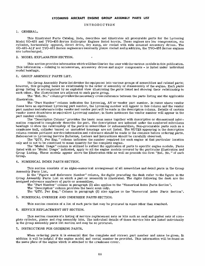
LYCOMING AIRCRAFT ENGINE GROUP ASSEMBLY PARTS LIST
INTRODUCTION
1 GENERAL.
This Illustrated Parts Catalog, lists, describes and illustrates all procurable parts for the LycomingModel VO-435 and TVO-435 Series Helicopter Engines listed herein. These engines are low compression, sixcylinder, horizontally opposed, direct drive, dry sump, air cooled with side mounted accessory drives. TheVO-435-A1F and TVO-435 Series engines are internally piston cooled and in addition, the TVO-435 Series enginesare turbocharged.
2. MODEL EXPLANATION SECTION.
This section provides information which will familiarize the user with the various models in this publication.This information - relating to accessories, accessory drives and major components - is listed under individualmodel headings.
3. GROUP ASSEMBLY PARTS LIST.
The Group Assembly Parts list divides the equipment into various groups of assemblies and related parts;however, this grouping bears no relationship to the order of assembly or disassembly of the engine. Each partsgroup listing is accompanied by an exploded view illustrating the parts listed and showing their relationship toeach other. The illustrations are adjacent to each parts group.
The "Ref. No." columnprovides the necessary cross reference between the parts listing and the applicableillustration.
The "Part Number" column indicates the Lycoming, AN or vendor part number. In cases where vendoritems have an equivalent Lycoming part number, the Lycoming number will appear in this column and the vendorpart number and reference to the vendor and vendor part will be made in the description column. Details of certainvendor items do not have an equivalent Lycoming number; in these instances the vendor number will appear in thepart number column.
The "Description Column" provides the basic noun name together with descriptive or dimensional infor-mation required to completely describe the part. The descriptions are indented under the numbered subcolumnheadings to show the relationship of the parts to assemblies or subassemblies, Non-procurable parts such as acrankcase half, cylinder barrel or unstudded housings are not listed. The NOTES appearing in the descriptioncolumn contain pertinent service information and reference should be made to the contents before ordering parts.References to Lycoming Service Bulletins, Letters and Instructions should be carefully observed.
The "QTY. Per Eng. " column indicates the number required for each engine at that particular locationonly and is not to be construed to mean quantity for the complete engine.
The "Model Usage" column is utilized to reflect the application of parts to specific engine models. Partslisted with no "Model Usage" indicated, apply to all the engine models covered by the particular Illustration andGroup Listing. These models appear above the Illustration title as well as precede the first "Ref. No. " of eachGroup.
4. NUMERICAL INDEX PARTS SECTION.
This section consists of an alpha-numerical arrangement of all assemblies and detail parts in the GroupAssembly Parts List.
In the "Figure and Reference Number" column, the digits preceding the dash refer to the figure in theGroup Assembly Parts List on which a part or assembly is illustrated. The digits following the dash are theassigned reference numbers of parts or assemblies.
The "Part Number" column in paragraph (3) also applies to the "Numerical Index Parts Section".The "Description" column provides the basic noun only.The "QTY. Per Eng. " Column in paragraph (3) also applies to the "Numerical Index Parts Section".
5. NUMERICAL OVERSIZE AND UNDERSIZE PARTS SECTION.
This section consists of a list of such parts that may be procured in sizes other than standard.
6. SERVICE REPLACEMENT SET SECTION.
This section consists of a listing of service replacement sets or kits such as seal and gasket sets of com-plete cylinder, piston and ring assembly kits. The individual details of these service kits are listed individuallyin the group assembly parts list section and may be so procured.
7. INSTRUCTIONS FOR ORDERING PARTS.
When ordering parts it is essential that the complete and correct part number and name be given. Inaddition it will be helpful if the engine model and serial number be provided. This information will be found onthe name plate of the engine which is attached to the crankcase cover.
iii
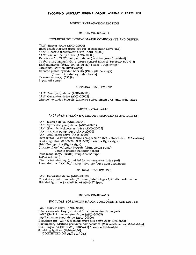
LYCOMING AIRCRAFT ENGINE GROUP ASSEMBLY PARTS LIST
MODEL EXPLANATION SECTION
MODEL VO-435-A1B
INCLUDES FOLLOWING MAJOR COMPONENTS AND DRIVES:
"AN" Starter drive (AND-20004)Hand crank starting (provided for at generator drive pad)"AN" Electric tachometer drive (AND-20005)"AN" Vacuum pump drive (AND-20000)Provision for "AN" fuel pump drive (no drive gear furnished)Carburetor, Manual alt. mixture control Marvel-Schebler MA-4-5)Dual magnetos (S6LN-20, S6RN-21) 1 each - lightweightShielding, Ignition (lightweight)Chrome plated cylinder barrels (Plain piston rings)
(Caustic treated cylinder heads)Crankcase assy. (69628)3-Pad oil sump
OPTIONAL EQUIPMENT
"AN" Fuel pump drive (AND-20003)"AN" Generator drive (AND-20002)Nitrided cylinder barrels (Chrome plated rings) 1/2" dia. exh. valve
MODEL VO-435-A1C
INCLUDES FOLLOWING MAJOR COMPONENTS AND DRIVES:
"AN" Starter drive (AND-20004)"AN" Hydraulic pump drive (AND-20001)"AN" Electric tachometer drive (AND-20005)"AN" Vacuum pump drive (AND-20000)"AN" Fuel pump drive (AND-20003)Carburetor, Altitude pressure compensator (Marvel-Schebler MA-4-5AA)Dual magnetos (S6LN-20, S6RN-21) 1 each - lightweightShielding ignition (lightweight)Chrome plated cylinder barrels (plain piston rings)
(Caustic treated cylinder heads)Crankcase assy. (70403) wrap-around type4-Pad oil sumpHand crank starting (provided for at generator drive pad)Provision for "AN" fuel pump drive (no drive gear furnished)
OPTIONAL EQUIPMENT
"AN" Generator drive (AND-20002)Nitrided cylinder barrels (Chrome plated rings) 1/2" dia. exh. valveShielded ignition (conduit type) AN-I-27 Spec.
MODEL VO-435-A1D
INCLUDES FOLLOWING MAJOR COMPONENTS AND DRIVES:
"AN" Starter drive (AND-20004)Hand crank starting (provided for at generator drive pad)"AN" Electric tachometer drive (AND-20005)"AN" Vacuum pump drive (AND-20000)Provision for "AN" fuel pump drive (No drive gear furnished)Carburetor, Altitude pressure compensator (Marvel-Schebler MA-4-5AA)Dual magnetos (S6LN-20, S6RN-21) 1 each - lightweightShielding ignition (lightweight)
(CONTINUED ON NEXT PAGE)
iv
LYCOMING AIRCRAFT ENGINE GROUP ASSEMBLY PARTS LIST
MODEL EXPLANATION SECTION
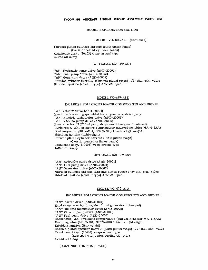
MODEL VO-435-A1D (Continued)
Chrome plated cylinder barrels (plain piston rings)(Caustic treated cylinder heads)
Crankcase assy. (70403) wrap-around type4-Pad oil sump
OPTIONAL EQUIPMENT
"AN" Hydraulic pump drive (AND-20001)"AN" Fuel pump drive (AND-20003)"AN" Generator drive (AND-20002)Nitrided cylinder barrels, (Chrome plated rings) 1/2" dia. exh. valveShielded ignition (conduit type) AN-I-27 Spec.
MODEL VO-435-A1E
INCLUDES FOLLOWING MAJOR COMPONENTS AND DRIVES:
"AN" Starter drive (AND-20004)Hand crank starting (provided for at generator drive pad)"AN" Electric tachometer drive (AND-20005)"AN" Vacuum pump drive (AND-20000)Provision for "AN" fuel pump drive (no drive gear furnished)Carburetor, Alt. pressure compensator (Marvel-Schebler MA-4-5AA)Dual magnetos (S6LN-204, S6RN-200) 1 each - lightweightShielding ignition (lightweight)Chrome plated cylinder barrels (Plain piston rings)
(Caustic treated cylinder heads)Crankcase assy. (70403) wrap-around type4-Pad oil sump
OPTIONAL EQUIPMENT
"AN" Hydraulic pump drive (AND-20001)"AN" Fuel pump drive (AND-20003)"AN" Generator drive (AND-20002)Nitrided cylinder barrels (Chrome plated rings) 1/2" dia. exh. valveShielded ignition (conduit type) AN-I-27 Spec.
MODEL VO-435-A1F
INCLUDES FOLLOWING MAJOR COMPONENTS AND DRIVES:
"AN" Starter drive (AND-20004)Hand crank starting (provided for at generator drive pad)"AN" Electric tachometer drive (AND-20005)"AN" Vacuum pump drive (AND-20000)"AN" Fuel pump drive (AND-20003)Carburetor, Alt. Pressure compensator (Marvel-Schebler MA-4-5AA)Dual magnetos (S6LN-204, S6RN-200) 1 each - lightweightShielding ignition (lightweight)Chrome plated cylinder barrels (plain piston rings) 1/2" dia. exh. valveCrankcase Assy. (70403) wrap-around type
(Equipped with piston cooling oil jets.)4-Pad oil sump
(CONTINUED ON NEXT PAGE)
v
LYCOMING AIRCRAFT ENGINE GROUP ASSEMBLY PARTS LIST
MODEL EXPLANATION SECTION
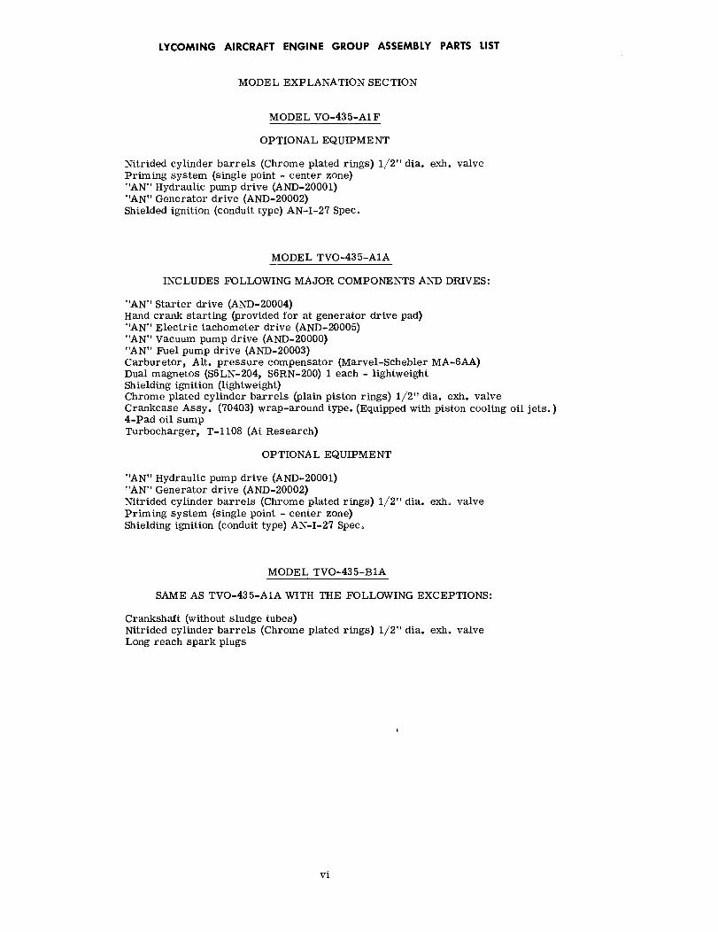
MODEL VO-435-A1F
OPTIONAL EQUIPMENT
Nitrided cylinder barrels (Chrome plated rings) 1/2" dia. exh. valvePriming system (single point - center zone)"AN" Hydraulic pump drive (AND-20001)"AN" Generator drive (AND-20002)Shielded ignition (conduit type) AN-I-27 Spec.
MODEL TVO-435-A1A
INCLUDES FOLLOWING MAJOR COMPONENTS AND DRIVES:
"AN" Starter drive (AND-20004)Hand crank starting (provided for at generator drive pad)"AN" Electric tachometer drive (AND-20005)"AN" Vacuum pump drive (AND-20000)"AN" Fuel pump drive (AND-20003)Carburetor, Alt. pressure compensator (Marvel-Schebler MA-6AA)Dual magnetos (S6LN-204, S6RN-200) 1 each - lightweightShielding ignition (lightweight)Chrome plated cylinder barrels (plain piston rings) 1/2" dia. exh. valveCrankcase Assy. (70403) wrap-around type. (Equipped with piston cooling oil jets.)4-Pad oil sumpTurbocharger, T-1108 (Ai Research)
OPTIONAL EQUIPMENT
"AN" Hydraulic pump drive (AND-20001)"AN" Generator drive (AND-20002)Nitrided cylinder barrels (Chrome plated rings) 1/2" dia. exh. valvePriming system (single point - center zone)Shielding ignition (conduit type) AN-I-27 Spec.
MODEL TVO-435-B1A
SAME AS TVO-435-A1A WITH THE FOLLOWING EXCEPTIONS:
Crankshaft (without sludge tubes)Nitrided cylinder barrels (Chrome plated rings) 1/2" dia. exh. valveLong reach spark plugs
vi

LYCOMING AIRCRAFT ENGINE GROUP ASSEMBLY PARTS LIST
FIGURE 1 - CRANKCASE GROUP
Ref.No.
PartNumber
DescriptionQty.perEng.
ModelUsage1 2 3 4 5
1-1 69628
2 STD-8723 STD-94 STD-5965 STD-86 STD-1607 STD-338 STD-678
9 STD-55710 6673411 6699012 50-1513 38-1314 25-1315 6875116 110217 38D-1918 STD-131519 38-1920 38-2121 6500722 25-823 31-1524 38-1225 STD-40526 STD-4727 6958028 6982329 25-1130 6745331 25-1232 72075
APPLICABLE MODEL - VO-435-A1B
CRANKCASE ASSEMBLY, Machining
NOTE
69628 crankcase assy. which requires either 69661or 70293 acc. hsg. assy. is no longer available. If69628 crankcase assy. need be replaced; servicewith 70403 crankcase assembly. Accessory hsg.assy. 69661 or 70293 must be modified to use withwrap-around crankcase (70403) by restudding thecrankcase mating surface in the following manner:
When facing the crankcase mating surface ofthe 69661 or 70293 acc. hsg., replace the two25-23 studs at the 11 and 1 o'clock position withtwo 25-13 studs, also, replace the 25-28 studimmediately to the right of the two 25-23 studs(or at the 2 o'clock position) with a 25-12 stud.No other changes to the acc. hsgs. are required.
CAUTION
Only STD-1688 bolts may be used to attach thecrankcase cover (68951) to the 69661 or 70293acc. hsg. due to the use of STD-1173 insertsat this location.
ATTACHING PARTS
NUT, Slotted, 3/8-24NUT, Plain, 1/4-28NUT, Plain, 3/8-24 x 21/64 in. thickWASHER, Plain, 1/4 in.WASHER, Lock internal teeth, 1/4 in.WASHER, Plain, 3/8 in.WASHER, Lock internal teeth, 3/8 in.
DOWEL, Hollow, 1/2 dia. x 11/16 in. longSTUD, 1/2-13 x 9-7/8 in. longSTUD, 5/16-18 x 1-1/2 in. longSTUD, 1/2-13 x 1-7/8 in. longSTUD, 3/8-16 x 1-5/8 in. longSTUD, 1/4-20 x 1-5/8 in. longSTUD, 1/2-20 x 10-21/32 in. longPLUG, Allen, 1/8-27 NPTSTUD, 3/8-16 x 2-3/8 in. longINSERT, Hell-Coil, 1/4-28 x 1/2 in. longSTUD, 3/8-16 x 2-3/8 in. longSTUD, 3/8-16 x 2-1/2 in. longRETAINER, Shroud tube sealSTUD, 1/4-20 x 1.00 in. longSTUD, 5/16-18 x 1-7/8 in. longSTUD, 3/8-16 x 1-1/2 in. longPLUG, 1/8 in. pipe, square hd. drilledPLUG, Allen, 1/4 in. pipeDOWEL, 5/16 dia. x 5/8 in. longSTUD, Drilled, 7/16-20 x 2 in. longSTUD, 1/4-20 x 1-3/8 in. longDOWEL, Crankshaft bearingSTUD, 1/4-20 x 1-1/2 in. long
SEAL, Oil, 3/32 dia. section x 15/32 in. ID
1
1
4737773
246
1224
7444322
124321228
22848

CR
AN
KC
AS
E A
SS
Y. R
EF.
NO
. I

LYCOMING AIRCRAFT ENGINE GROUP ASSEMBLY PARTS LIST
FIGURE 2 - CRANKCASE GROUP
Ref.No.
PartNumber
Description1 2 3 4 5
Qty.perEng.
ModelUsage
APPLICABLE MODELS - VO-435-A1C, A1D, A1E, A1F, TVO-435-A1A AND B1A
2-1 70403
1A 73697
2 AN6-163 AN6-244 AN6-21A5 AN6-22A6 STD-337 STD-8728 STD-7139 STD-67810 STD-59611 STD-123012 AN4-1613 STD-814 STD-16015 STD-916 STD-97
17 STD-55718 6673419 6699020 50-1521 38-1322 68751
69679
23 STD-131524 6500725 31-2126 STD-740
27 STD-40528 38D-1929 31-15
30 31-2431 6958032 6982333 110234 25-1135 6979636 STD-78337 25-1038 STD-162339 7033840 73772
41 72075
CRANKCASE ASSEMBLY, MachiningRequires use of accessory housing assemblies 70404or 70406 unless old acc. hsg. assemblies 69661 or70293 are reworked. See "NOTE", referencenumber, 1-1.
CRANKCASE ASSEMBLY, MachiningThis crankcase assy. is machined for use of six(73772) piston cooling nozzle assemblies.
ATTACHING PARTS
BOLT, Hex hd. dr. shank, 3/8-24 x 1-53/64 in. longBOLT, Hex. hd. dr. shank, 3/8-24 x 2-37/64 in. longBOLT, Hex. hd., 3/8-24 x 2-13/64 in. longBOLT, Hex. hd., 3/8-24 x 2-21/64 in. longWASHER, Plain, 3/8 in.NUT, Slotted, 3/8-24PIN, 3/32 dia. x 3/4 in. longWASHER, Shakeproof lock, 3/8 in.NUT, Plain, 3/8-24BOLT, Hex. head, 1/4-28 x 1-9/32 in. longBOLT, Hex. hd., dr. shank, 1/4-28 x 1-25/32 in. longWASHER, Plain, 1/4 in.WASHER, Internal teeth, 1/4 in. lockNUT, Plain, 1/4-28NUT, Slotted, 1/4-28
DOWEL, Hollow, 1/2 dia. x 11/16 in. longSTUD, 1/2-13 x 9-7/8 in. longSTUD, 5/16-18 x 1-1/2 in. longSTUD, 1/2-13 x 1-7/8 in. longSTUD, 3/8-16 x 1-5/8 in. longSTUD, 1/2-20 x 10-21/32 in. long
68751 stud is a detail part of 70403 crankcaseassy.
STUD, 9/16-18 x 10-21/32 in. long69679 stud is adetailpart of 73697 crankcase assy.
INSERT, Heli-Coil, 1/4-28 x 1/2 in. longRETAINER, Shroud tube sealSTUD, 5/16-18 x 2-5/8 in. longPLUG, Slotted, 3/4 in. pipe (shipping part; not
illustrated)PLUG, Sq. hd. dr., 1/8-27 NPTSTUD, Dr., 3/8-16 x 2-3/8 in. longSTUD, 5/16-18 x 1-7/8 in. long
Replaces 31-14 stud.STUD, 5/16-18 x 3.00 in. longDOWEL, 5/16 dia. x 5/8 in. longSTUD, Drilled, 7/16-14 N. Formx 2.00 in. longPLUG, Allen, 1/8-27 NPTSTUD, 1/4-20 x 1-3/8 in. longDOWEL, Crankshaft bearingPLUG, Allen, 1/4-18 NPTSTUD, 1/4-20 x 1-1/4 in.INSERT, Heli-Coil, 1/4-20 x 3/8 in. long
SPACER, Breather housing (shipped lose) not illustratedNOZZLE ASSY., Piston cooling
SEAL, Oil, 3/32 dia. section x 15/32 in. ID
3
1 VO-435-A1C, A1D,A1E
1 VO-435-A1F, TVO-435-A1A, B1A
1231
16414476
26776
246
12244 VO-435-A1C, A1D,
A1E
4 VO-435-A1F, TVO-435-A1A, B1A
1712
21
111
12844821126
8
VO-435-A1F, TVO-435-A1A, B1A

26
41
7 8
6 2
33
32
19
ALL
INS
ER
TS O
N B
OTT
OM
AN
D S
IDE
S A
RE
RE
F. N
O.2
3 C
RA
NK
CA
SE
AS
SE
MB
LIE
S-R
EF.
NO
S. I-
IA
LYCOMING AIRCRAFT ENGINE GROUP ASSEMBLY PARTS LIST
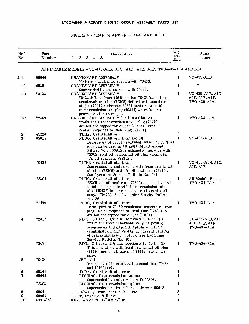
FIGURE 3 - CRANKSHAFT AND CAMSHAFT GROUP
Ref.No.
PartNumber
DescriptionQty.perEng.
ModelUsage1 2 3 4 5
APPLICABLE MODELS - VO-435-A1B, A1C, A1D, A1E, A1F, TVO-435-A1A AND B1A
3-1 69640
1A 69851
1B 70433
1C 72469
2 452263 69815
70432
72305
72470
4 72312
72471
5 70434
6 698447 69642
72308
8 696419 6896510 STD-858
CRANKSHAFT ASSEMBLYNo longer available; service with 70433.
CRANKSHAFT ASSEMBLYSuperseded by and service with 70433.
CRANKSHAFT ASSEMBLY70433 differs from 69851 in that 70433 has a frontcrankshaft oil plug (72305) drilled and tapped foroil jet (70434); whereas 69851 contains a solidfront crankshaft oil plug (69815) which has noprovisions for an oil jet.
CRANKSHAFT ASSEMBLY (Bell installation)72469 has a front crankshaft oil plug (72470)drilled and tapped for oil jet (70434). Plug(72470) requires oil seal ring (72471).TUBE, Crankshaft oilPLUG, Crankshaft oil, front (solid)
Detail part of 69851 crankshaft assy. only. Thisplug can be used in all installations exceptHiller. When 69815 is exhausted; service with72305 front oil crankshaft oil plug along withit's oil seal ring (72312).
PLUG, Crankshaft oil, frontSuperseded by and service with front crankshaftoil plug (72305) and it's oil seal ring (72312).See Lycoming Service Bulletin No. 261,
PLUG, Crankshaft oil, front72305 and oil seal ring (72312) supersedes andis interchangeable with front crankshaft oilplug (70432) in current version of crankshaftassy. (70433). See Lycoming Service BulletinNo. 261.
PLUG, Crankshaft oil, frontDetail part of 72469 crankshaft assembly. Thisplug, which requires oil seal ring (72471) isdrilled and tapped for oil jet (70434).
RING, Oil seal, 1/8 dia. section x 1.00 in. ID72312 and front crankshaft oil plug (72305)supersedes and interchangeable with frontcrankshaft oil plug (70432) in current versionof crankshaft assy. (70433). See LycomingService Bulletin No. 261.
RING, Oil seal, 1/8 dia. section x 13/16 in. IDThis ring along with front crankshaft oil plug(72470) are detail parts of 72469 crankshaftassy.
JET, OilIncorporated in crankshaft assemblies (70433and 72469) only.
TUBE, Crankshaft oil, rearBUSHING, Rear crankshaft spline
Superseded by and service with 72308.BUSHING, Rear crankshaft spline
Supersedes and interchangeable with 69642.DOWEL, Rear crankshaft spline
BOLT, Crankshaft flangeKEY, Woodruff, 5/32 x 5/8 in.
1 VO-435-A1B
1
1 VO-435-A1B, A1CA1D, A1E, A1F,TVO-435-A1A
1 TVO-435-B1A
61 VO-435-A1B
1 VO-435-A1B, A1C,A1D, A1E
1 All Models ExceptTVO-435-B1A
1 TVO-435-B1A
1 VO-435-A1B, A1C,A1D, A1E, A1F,TVO-435-A1A
1 TVO-435-B1A
1
11
1
381
5


LYCOMING AIRCRAFT ENGINE GROUP ASSEMBLY PARTS LIST
FIGURE 3 - CRANKSHAFT AND CAMSHAFT GROUP
Ref.No.
PartNumber
DescriptionQty.perEng.
ModelUsage1 2 3 4 5
3-11 67687 GEAR, Crankshaft timing
ATTACHING PARTS
1
12 6720413 67688
14 67447
6876315 69529
72877
73061
16 71791
72876
PLATE, Crankshaft gear lockNUT, Crankshaft gear retaining
BEARING, CrankshaftWhen supply of 67447 is exhausted; service with68763.
BEARING, Crankshaft (Alternate to 67447, use in pairs)BODY, Hydraulic tappet
(Straight body, narrow seat.)BODY, Hydraulic tappet
(Straight body, wide seat.)BODY, Hydraulic tappet
(Hyperbolic body, wide seat.)PLUNGER ASSY., Hydraulic tappet
(Fast leakdown, narrow seat.)PLUNGER ASSY., Hydraulic tappet
(Fast leakdown, wide seat.)
11
8
812
12
12
12
12
NOTE
Plunger assembly 71791 could be used only with69529 tappet body, (these two parts are notprocurable). Plunger assy. 72876 can be usedwith 69529, 72877 or 73061 bodies. See LycomingService Instruction No. 1011A for furtherinformation concerning hydraulic body andplunger assemblies.
17 6507418 7130419 STD-1066
20 69662
SOCKET, Push rod, hydraulic tappetCAMSHAFT ASSY.
DOWEL, Stepped, .310 and .251 dia. x 13/32 in.long
GEAR, Camshaft
1211
1
ATTACHING PARTS
21 66144
72078
22 STD-679
LOCKPLATE, 5/16 bolt x 1-21/64 in. spacingSuperseded by and service with 72078.
LOCKPLATE, 5/16 bolt x 1-21/64 in. spacingSupersedes and interchangeable with 66144.
SCREW, 5/16-24 x 27/64 in. long
2
2
4
7

LYCOMING AIRCRAFT ENGINE GROUP ASSEMBLY PARTS LIST
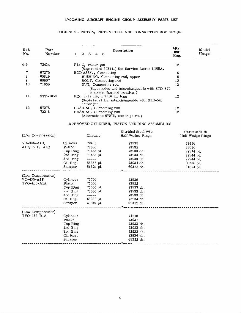
FIGURE 4 - PISTON, PISTON RINGS AND CONNECTING ROD GROUP
Ref.No.
PartNumber
Description Qty.perEng.
ModelUsage1 2 3 4 5
APPLICABLE MODELS - VO-435-A1B, A1C, A1D, A1E, A1F, TVO-435-A1A, B1A
4-1 71553
71553
PISTON, 4-ring (anodized)(Used with chrome cylinder assembly.)Superseded by 73620 (5 ring) piston beginning engineserial number 2824-31, 2827-31 and up. May beserviced with 73620 in complete sets only withassociated rings.
PISTON, 4-ring (anodized)(Used with chrome cylinder assembly.)
6 VO-435-A1B, A1C,A1D, A1E
6 TVO-435-A1A,VO-435-A1F
NOTE
Requires 2-71555, 1-68338 and 1-61824 unplatedrings.
1A 73620 PISTON, 5-ring (anodized)(Used with 72436 chrome cylinder assembly.)
6 VO-435-A1D, A1E
NOTE
Requires 3-72944, 1-68338 and 1-61824 unplatedrings. Piston (73620) supersedes and is inter-changeable with piston (71553) in complete setsonly, beginning engine serial number 2824-31,2827-31 and up. A supply of 71553 is beingmaintained for service purposes.
73932
73932
2 71555
2A 72944
73933
3 68338
3A 68338
73934
4 61824
4A 61824
69322
5 60403
PISTON, 5-ring (anodized)(Used with 73935 nitrided, cylinder assembly)
PISTON, 5-ring (anodized)(Used with 74218 nitrided cylinder assembly.)
RING, Piston, top compression (plain, full wedge)(Used with piston 71553.)
RING, Piston, top compression (plain, half wedge)(Used with piston 73620.)
RING, Piston, top compression (chrome, half wedge)(Used with piston 73932.)
RING, Piston, oil regulating, expander type (plain)(Used with piston 71553.)
RING, Piston, oil regulating, expander type(Used with piston 73620.)
RING, Piston, oil regulating, expander type(Used with piston 73932.)
RING, Piston, scraper(Used with piston 71553)
RING, Piston, scraper(Used with piston 73620)
RING, Piston, scraper(Used with piston 73932.)
PIN, Piston
6 VO-435-A1D, A1E,A1F, TVO-435-A1A
6 TVO-435-B1A
12 VO-435-A1B, A1C,A1D, A1E, A1F,TVO-435-A1A
18 VO-435-A1D, A1E
18 VO-435-A1D, A1E,A1F, TVO-435-A1A,B1A
6 VO-435-A1B,A1C,A1D, A1E, A1F,TVO-435-A1A
6 VO-435-A1D, A1E
6 VO-435-A1D, A1E,A1F, TVO-435-A1A,B1A
6 VO-435-AB, A1C,A1D, A1E, AIF,TVO-435-A1A
6 VO-435-A1D, A1E
6 VO-435-A1D, A1E,A1F, TVO-435-A1A,B1A
6
8
LYCOMING AIRCRAFT ENGINE GROUP ASSEMBLY PARTS LIST
FIGURE 4 - PISTON, PISTON RINGS AND CONNECTING ROD GROUP
Ref.No.
PartNumber
DescriptionQty.perEng.
ModelUsage1 2 3 4 5
4-6 72434
7 672758 658199 6000710 71950
11 STD-1853
12 6727672218
PLUG, Piston pin(Superseded 60311.) See Service Letter L108A.
ROD ASSY., ConnectingBUSHING, Connecting rod, upperBOLT, Connecting rodNUT, Connecting rod
(Supersedes and interchangeable with STD-872at connecting rod location.)
PIN, 3/32 dia. x 9/16 in. long(Supersedes and interchangeable with STD-543cotter pin. )
BEARING, Connecting rodBEARING, Connecting rod
(Alternate to 67276, use in pairs.)
12
66
1212
12
1212
APPROVED CYLINDER, PISTON AND RING ASSEMBLIES
Nitrided Steel WithHalf Wedge Rings(Low Compression) Chrome
Chrome WithHalf Wedge Rings
VO-435-A1B, Cylinder 72436 73935 72436A1C, A1D, A1E Piston 71553 73932 73620
Top Ring 71555 pl. 73933 ch. 72944 pl.2nd Ring 71555 pl. 73933 ch. 72944 pl.3rd Ring ---- 73933 ch. 72944 pl.Oil Reg. 68338 pl. 73934 ch. 68338 pl.Scraper 61824 pl. 69322 ch. 61824 pi.
(Low Compression)VO-435-A1F Cylinder 73704 73935TVO-435-A1A Piston 71553 73932
Top Ring 71555 pl. 73933 ch.2nd Ring 71555 pl. 73933 ch.3rd Ring ----- 73933 ch.Oil Reg. 68338 pl. 73934 ch.Scraper 61824 pl. 69322 ch.
(Low Compression)TVO-435-B1A Cylinder 74218
Piston 73932Top Ring 73933 ch.2nd Ring 73933 ch.3rd Ring 73933 ch.Oil Reg. 73934 ch.Scraper 69322 ch.
9

LYCOMING AIRCRAFT ENGINE GROUP ASSEMBLY PARYS LIST
I2
7
IO II
ALL MODELS
Figure 4 - Piston, Piston Rings and Connecting Rod Group
10

LYCOMING AIRCRAFT ENGINE GROUP ASSEMBLY PARTS LIST
FIGURE 5 - CYLINDER GROUP
Ref.No.
PartNumber
DescriptionQty.perEng.
ModelUsage1 2 3 4 5
APPLICABLE MODELS - VO-435-A1B, A1C, A1D, A1E, A1F, TVO-435-A1A, B1A
5-1 70353
1A 71850
1B 72436
CYLINDER ASSY. (Chrome plated)(Caustic treated for weight reduction.)70353 cylinder assy. incorporates exhaust valveguide 69358 to receive a (66714) solid stem exhaustvalve. This solid stem valve may be replaced witha sodium cooled valve by complying with LycomingService Instruction No. 1000. If 70353 need bereplaced; service with 72436 cyl. assy. and relatedsodium cooled parts.
CYLINDER ASSY. (Chrome plated.)(Caustic treated for weight reduction.)71850 differs from 70353 only in the thread fitbetween the head and barrel. If 71850 need bereplaced; service with 72436 cyl. assy. and relatedsodium cooled parts.
CYLINDER ASSY. (Chrome plated)(Caustic treated for weight reduction.)72436 differs from 71850 cyl. assy.in that 72436employs the use of a 7/16 in. dia. sodium cooledexhaust valve and related parts.
6 VO-435-A1B,A1C
6 VO-435-A1B,A1C,AID
6 VO-435-A1D, A1E
NOTE
Later versions of 72436 cyl. assy. do not incorporateSTD-859 dowel at rocker shaft bushing.
1C 73704
1D 73935
1E 74218
CYLINDER ASSY. (Chrome plated)This cyl. assy. incorporates flange type valveseats and has provisions for 1/2 in. dia. sodiumcooled exhaust valve.
CYLINDER ASSY. (Nitrided)This cyl. assy. incorporates flange type valveseats and has provisions for 1/2 in. dia. sodiumcooled exhaust valve.
CYLINDER ASSY. (Nitrided)This cyl. assy. incorporates flange type valveseats and a ni-resist exhaust valve guide (73979)to receive (74052) 1/2 in. dia. inconel sodiumcooled exhaust valve. Requires the use of longreach spark plugs.
6 VO-435-A1F,TVO-435-A1A
6 VO-435-AE, A1F,TVO-435-A1A
6 TVO-435-B1A
ATTACHING PARTS
2 STD-5283 STD-5294 383-B5 STD-39
6 66720
71895
NUT, Plain, 1/2-20LOCKNUT, Palnut, 1/2 in.NUT, Plain, 3/8-24LOCKNUT, Palnut, 3/8 in.
SEAT, Intake valveDetail part of cylinder assemblies, 70353,71850 and 72436.
SEAT, Intake valve (Flange type)Detail part of cylinder assemblies, 73704,73935 and 74218.
24242424
6 VO-435-A1B, A1C,AID, A1E
6 VO-435-A1E,A1F,TVO-435-A1A, B1A
11


LYCOMING AIRCRAFT ENGINE GROUP ASSEMBLY PARTS LIST
FIGURE 5 - CYLINDER GROUP
Ref.No.
PartNumber
DescriptionQty.perEng.
ModelUsage1 2 3 4 5
5-7 67835
71894
8 667139 69358
69693
72897
73979
10 66796 P10
69260 P10
11 31-1212 25-1213 6667014 STD-859
15 25-816 69814
17 STD-783
18 72343
19 72344
20 73129
SEAT, Exhaust valveDetail part of cylinder assemblies, 70353,71850 and 72436.
SEAT, Exhaust valve (Flange type)Detail part of cylinder assemblies, 73704,73935 and 74218.
GUIDE, Valve, intakeGUIDE, Valve, exhaust
Detail part of cylinder assemblies, 70353and 71850. This guide receives (66714)solid stem exhaust valve. Refer to LycomingService Instruction No. 1000.
GUIDE, Valve, exhaustDetail part of cylinder assembly, 72436.This guide receives (71381) 7/16 in. dia,sodium cooled exhaust valve.
GUIDE, Valve, exhaustDetail part of cylinder assemblies, 73704and 73935. This guide receives either a(73111 or 73875) 1/2 in. dia. sodium cooledexhaust valve.
GUIDE, Valve, exhaust (ni-resist)Detail part of 74218 cylinder assembly.This guide receives (74052) 1/2 in. dia.inconel sodium cooled exhaust valve.
INSERT, Spark plug, 18-1. 5MM (Short reach)(Available in P10 oversize only.)Detail part of cylinder assemblies, 70353,71850, 72436, 73704 and 73935.
INSERT, Spark plug, 18-1. 5 MM (Long reach)(Available in P10 oversize only.)Detail part of 74218 cylinder assembly.
STUD, 5/16-18 x 1-1/2 in. longSTUD, 1/4-20 x 1-1/2 in. longBUSHING, Rocker shaft innerDOWEL, 1/8 dia. x 9/32 in. long
Detail part of cylinder assemblies 70353,71850 and 72436. See "NOTE", reference 1B.
STUD, 1/4-20 x 1.00 in. longDECAL, Chrome cylinder identification (Opt.
Equipt. )Detail part of cylinder assemblies, 70353and 71850.
PLUG, Allen, 1/4-18 NPT(Supersedes STD-47)
STABILIZER, Cylinder head fins, 15 teethDetail part of 74218 cylinder assy.
STABILIZER, Cylinder head fins, 26 teethDetail part of 74218 cylinder assy.
VALVE, IntakeSupersedes and interchangeable with 72612.
6 VO-435-A1B,A1C,A1D, A1E
6 VO-435-A1E, A1F,TVO-435-A1A, B1A
66 VO-435-A1B, A1C,
A1D
6 VO-435-A1D, A1E
6 VO-435-A1E,A1FTVO-435-A1A
6 TVO-435-B1A
12 VO-435-A1B, A1C,A1D, A1E, A1F,TVO-435-A1A
12 TVO-435-B1A
12122412 VO-435-A1B, A1C,
A1D, A1E
246 VO-435-A1B,A1C,
A1D
6
6 TVO-435-B1A
6 "
6
13

LYCOMING AIRCRAFT ENGINE GROUP ASSEMBLY PARTS LIST
FIGURE 5 - CYLINDER GROUP
Ref.No.
PartNumber
DescriptionQty.perEng.
ModelUsage1 2 3 4 5
5-21 66714
71381
73111
73875
74052
22 68325
68325
73112
23 6832624 6832825 68327
68327
69698
73115
26 60009
60009
72050
MS13997-3
27 69697
MS13998-3
28 7154971549-171549-271549-3
29 6711330 6711431 6880632 66732
VALVE, Exhaust, solid stemUsed with cylinder assemblies, 70353 and 71850.Refer to Lycoming Service Instruction No. 1000.
VALVE, Exhaust, sodium cooled (7/16 in. dia.)Used with 72436 cylinder assy.
VALVE, Exhaust, sodium cooled (1/2 in. dia.)Used with cylinder assemblies, 73704 and 73935.
VALVE, Exhaust, sodium cooled (1/2 in. dia.)(Alternate to 73111 exhaust valve.)
VALVE, Exhaust, sodium cooled, inconel (1/2 in. dia.)Used with 74218 cylinder assy.
SEAT, Valve spring, lower (exhaust and intake)Used with cylinder assemblies, 70353, 71850 and72436.
SEAT, Valve spring, lower (intake)Used with cylinder assemblies, 73704, 73935 and74218.
SEAT, Valve spring, lower (exhaust)Used with cylinder assemblies, 73704, 73935 and74218.
SPRING, Valve, outerSPRING, Valve, auxiliarySEAT, Valve spring (exhaust and intake)
Used with cylinder assemblies, 70353 and 71850.SEAT, Valve spring (intake)
Used with cylinder assemblies, 72436, 73704,73935 and 74218.
SEAT, Valve spring (exhaust)Used with 72436 cylinder assembly.
SEAT, Valve spring (exhaust)Used with cylinder assemblies, 73704, 73935 and74218
KEY, Valve (exhaust and intake)Used with cylinder assemblies, 70353 and 71850.
KEY, Valve (intake)Used with cylinder assemblies, 72436, 73704,73935 and 74218.
KEY, Valve (exhaust)Used with 72436 cylinder assembly.
KEY, Valve (exhaust)Used with cylinder assemblies; 73704, 73935 and74218.
CAP, Valve stemUsed with 72436 cylinder assembly
CAP, Valve stemUsed with cylinder assemblies, 73704, 73935 and74218.
WASHER, Valve rocker thrustWASHER, Valve rocker thrustWASHER, Valve rocker thrustWASHER, Valve rocker thrust
(A total of twelve (12)required; select forclearance; see Lycoming Service Bulletin No.225A.) 71549 supersedes 66719.
ROCKER ASSEMBLY, Intake valveBUSHING, Valve rocker
SHAFT, Valve rockerGASKET, Valve rocker shaft cover
6 VO-435-AB, A1C,A1D
6 VO-435-A1D, A1E
6 VO-435-A1E, AF,TVO-435-A1A
6
6 TVO-435-B1A
12 VO-435-A1B, A1C,A1D, A1E
6 VO-435-A1E, AF,TVO-435-A1A, B1A
6
121212 VO-435-A1B, A1C,
AID6 VO-435-A1D, AlE,
A1F, TVO-435-A1AB1A
6 VO-435-A1D, A1E
6 VO-435-A1E, AF,TVO-435-A1A, B1A
24 VO-435-A1B, A1C,A1D
12 VO-435-A1D, A1E,A1F, TVO-435-A1A,B1A
12 VO-435-A1D, A1E
12 VO-435-A1E, A1F,TVO-435-A1A, B1A
6 VO-435-A1D, A1E
6 VO-435-A1E, AIF,TVO-435-A1A, B1A
ARARARAR
66
1212
14
LYCOMING AIRCRAFT ENGINE GROUP ASSEMBLY PARTS LIST
FIGURE 5 - CYLINDER GROUP
Ref.No.
PartNumber
Description1 2 3 4 5
Qty.perEng.
ModelUsage
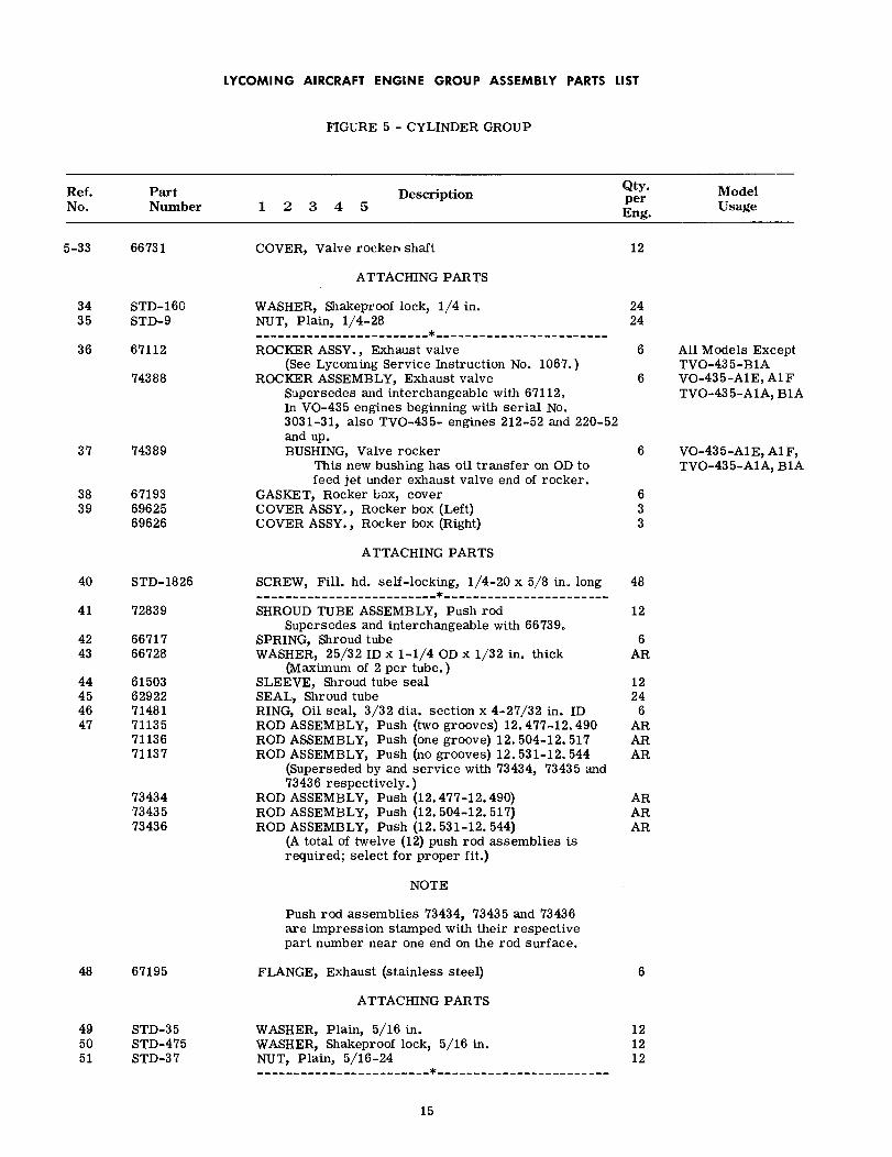
5-33 66731 COVER, Valve rocker shaft 12
ATTACHING PARTS
34 STD-16035 STD-9
36 67112
74388
37 74389
38 6719339 69625
69626
WASHER, Shakeproof lock, 1/4 in.NUT, Plain, 1/4-28
ROCKER ASSY., Exhaust valve(See Lycoming Service Instruction No. 1067.)
ROCKER ASSEMBLY, Exhaust valveSupersedes and interchangeable with 67112.In VO-435 engines beginning with serial No.3031-31, also TVO-435- engines 212-52 and 220-52and up.BUSHING, Valve rocker
This new bushing has oil transfer on OD tofeed jet under exhaust valve end of rocker.
GASKET, Rocker box, coverCOVER ASSY., Rocker box (Left)COVER ASSY., Rocker box (Right)
2424
6 All Models ExceptTVO-435-B1A
6 VO-435-AE, A1FTVO-435-A1A, B1A
6 VO-435-A1E, AF,TVO-435-A1A, B1A
633
ATTACHING PARTS
40 STD-1826
41 72839
42 6671743 66728
44 6150345 6292246 7148147 71135
7113671137
734347343573436
SCREW, Fill. hd. self-locking, 1/4-20 x 5/8 in. long
SHROUD TUBE ASSEMBLY, Push rodSupersedes and interchangeable with 66739.
SPRING, Shroud tubeWASHER, 25/32 ID x 1-1/4 OD x 1/32 in. thick
(Maximum of 2 per tube.)SLEEVE, Shroud tube sealSEAL, Shroud tubeRING, Oil seal, 3/32 dia. section x 4-27/32 in. IDROD ASSEMBLY, Push (two grooves) 12.477-12.490ROD ASSEMBLY, Push (one groove) 12. 504-12. 517ROD ASSEMBLY, Push (no grooves) 12. 531-12. 544
(Superseded by and service with 73434, 73435 and73436 respectively.)
ROD ASSEMBLY, Push (12.477-12.490)ROD ASSEMBLY, Push (12.504-12. 517)ROD ASSEMBLY, Push (12.531-12. 544)
(A total of twelve (12) push rod assemblies isrequired; select for proper fit.)
48
12
6AR
1224
6ARARAR
ARARAR
NOTE
Push rod assemblies 73434, 73435 and 73436are impression stamped with their respectivepart number near one end on the rod surface.
48 67195 FLANGE, Exhaust (stainless steel) 6
ATTACHING PARTS
49 STD-3550 STD-47551 STD-37
WASHER, Plain, 5/16 in.WASHER, Shakeproof lock, 5/16 in.NUT, Plain, 5/16-24
121212
15

LYCOMING AIRCRAFT ENGINE GROUP ASSEMBLY PARTS LIST
FIGURE 5 - CYLINDER GROUP
Ref.No.
PartNumber
DescriptionQty.perEng.
ModelUsage1 2 3 4 5
5-52 65614 PLUG, Baffle attaching 4
ATTACHING PARTS
53 STD-168754 STD-1686
WASHER, External teeth, no. 10 lockSCREW, Fill. head, no. 10-32 x 7/16 in. long
44
FIGURE 6 - INDUCTION SYSTEM GROUP
APPLICABLE MODELS - VO-435-A1B, A1C, A1D AND A1E
6-1 68951 COVER ASSY., Crankcase 1
ATTACHING PARTS
2 STD-83 STD-1604 STD-95 STD-1679
STD-16796 STD-12307 STD-1688
8 696029 31-1510 STD-405
74376
11 6154812 STD-1901
13 6817214 60069
73346
WASHER, Plain, 1/4 in.WASHER, Internal teeth, 1/4 in. lockNUT, Plain, 1/4-28BOLT, Hex. head, 1/4-28 x 1.00 in. long
BOLT, Hex. head, 1/4-28 x 1.00 in. longBOLT, Hex, head, 1/4-28 x 1-9/32 in. longBOLT, Hex. head, 1/4-20 x 1.00 in. long
CONNECTION, Intake pipeSTUD, 5/16-18 x 1-7/8 in. longPLUG, 1/8 in. pipe, square head drilled
ELBOW ASSY., Primer, 45 ° (single point primersystem, Bell installation; see "NOTE",Figure 16, reference 13.)
PLATE, NameSTUD, Drive, rd. head, no. 4 x 3/16 in. long
(Replaces AN535-4-3 screw.)GASKET, Oil sumpFLANGE, Intake pipe, upper
Replaced by 73346 upper intake pipe flange.60069 and 73346 are interchangeable.
FLANGE, Intake pipe, upper
34241014
1010
4
6411
VO-435-A1C, A1D,A1EVO-435-A1B
VO-435-A1B
VO-435-A1E
14
16
6
ATTACHING PARTS
15 STD-816 STD-16017 STD-9
18 6013119 68955
6895668957
20 STD-1792
WASHER, Plain, 1/4 in.WASHER, Internal teeth, 1/4 in. lockNUT, Plain, 1/4-28
GASKET, 2 bolt flange, 1-3/4 in. IDPIPE, Intake, cylinders no. 1 and 6PIPE, Intake, cylinders no. 2 and 5PIPE, Intake, cylinders no. 3 and 4HOSE, 1-3/4 ID x 2-3/16 OD x 2-3/8 in. long
121212
62226
16
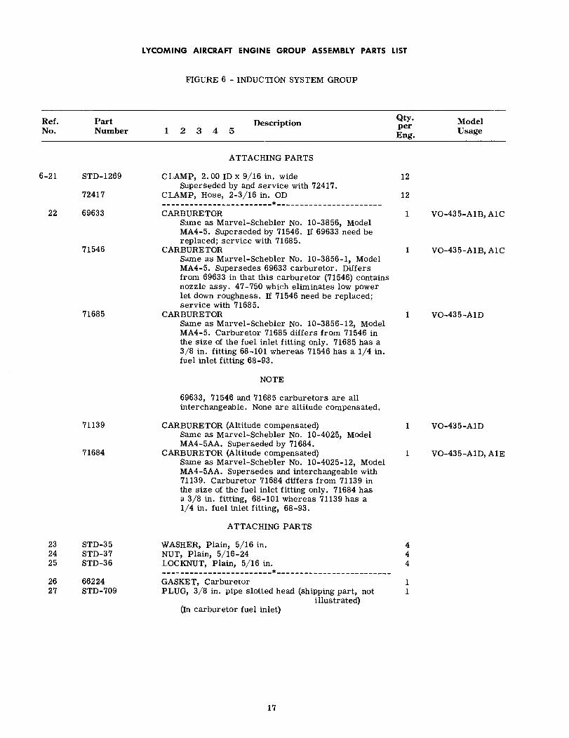
LYCOMING AIRCRAFT ENGINE GROUP ASSEMBLY PARTS LIST
FIGURE 6 - INDUCTION SYSTEM GROUP
Ref.No.
PartNumber
DescriptionQty.perEng.
ModelUsage1234 5
ATTACHING PARTS
6-21 STD-1269
72417
22 69633
71546
71685
CLAMP, 2.00 ID x 9/16 in. wideSuperseded by and service with 72417.
CLAMP, Hose, 2-3/16 in. OD
CARBURETORSame as Marvel-Schebler No. 10-3856, ModelMA4-5. Superseded by 71546. If 69633 need bereplaced; service with 71685.
CARBURETORSame as Marvel-Schebler No. 10-3856-1, ModelMA4-5. Supersedes 69633 carburetor. Differsfrom 69633 in that this carburetor (71546) containsnozzle assy. 47-750 which eliminates low powerlet down roughness. If 71546 need be replaced;service with 71685.
CARBURETORSame as Marvel-Schebler No. 10-3856-12, ModelMA4-5. Carburetor 71685 differs from 71546 inthe size of the fuel inlet fitting only. 71685 has a3/8 in. fitting 68-101 whereas 71546 has a 1/4 in.fuel inlet fitting 68-93.
12
12
1 VO-435-A1B,A1C
1 VO-435-A1B,A1C
1 VO-435-A1D
NOTE
69633, 71546 and 71685 carburetors are allinterchangeable. None are altitude compensated.
71139
71684
CARBURETOR (Altitude compensated)Same as Marvel-Schebler No. 10-4025, ModelMA4-5AA. Superseded by 71684.
CARBURETOR (Altitude compensated)Same as Marvel-Schebler No. 10-4025-12, ModelMA4-5AA. Supersedes and interchangeable with71139. Carburetor 71684 differs from 71139 inthe size of the fuel inlet fitting only. 71684 hasa 3/8 in. fitting, 68-101 whereas 71139 has a1/4 in. fuel inlet fitting, 68-93.
1 VO-435-A1D
1 VO-435-A1D, A1E
ATTACHING PARTS
23 STD-3524 STD-3725 STD-36
26 6622427 STD-709
WASHER, Plain, 5/16 in.NUT, Plain, 5/16-24LOCKNUT, Plain, 5/16 in.
GASKET, CarburetorPLUG, 3/8 in. pipe slotted head (shipping part, not
illustrated)(In carburetor fuel inlet)
444
11
17

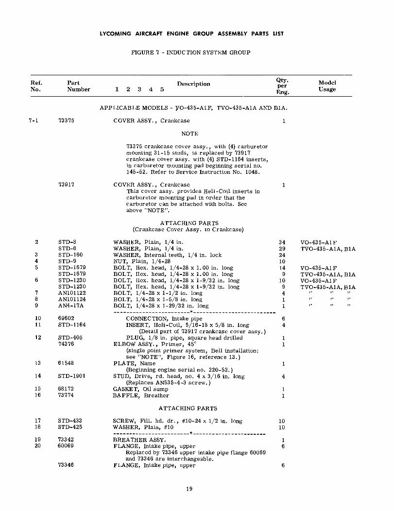
LYCOMING AIRCRAFT ENGINE GROUP ASSEMBLY PARTS LIST
FIGURE 7 - INDUCTION SYSTEM GROUP
Ref.No.
PartNumber
DescriptionQty.perEng.
ModelUsage1 2 3 4 5
APPLICABLE MODELS - VO-435-A1F, TVO-435-A1A AND B1A.
7-1 73375 COVER ASSY., Crankcase 1
NOTE
73917
73375 crankcase cover assy., with (4) carburetormounting 31-15 studs, is replaced by 73917crankcase cover assy. with (4) STD-1164 inserts,in carburetor mounting pad beginning serial no.145-52. Refer to Service Instruction No. 1048.
COVER ASSY., CrankcaseThis cover assy. provides Heli-Coil inserts incarburetor mounting pad in order that thecarburetor can be attached with bolts. Seeabove "NOTE".
ATTACHING PARTS(Crankcase Cover Assy. to Crankcase)
1
2 STD-8STD-8
3 STD-1604 STD-95 STD-1679
STD-16796 STD-1230
STD-12307 AN1011228 AN1011249 AN4-17A
10 6960211 STD-1164
12 STD-40574376
13 61548
14 STD-1901
15 6817216 73774
WASHER, Plain, 1/4 in.WASHER, Plain, 1/4 in.WASHER, Internal teeth, 1/4 in. lockNUT, Plain, 1/4-28BOLT,BOLT,BOLT,BOLT,BOLT,BOLT,BOLT,
Hex. head, 1/4-28 x 1.00 in. longHex. head, 1/4-28 x 1.00 in. longHex. head, 1/4-28 x 1-9/32 in. longHex. head, 1/4-28 x 1-9/32 in. long1/4-28 x 1-1/2 in. long1/4-28 x 1-5/8 in. long1/4-28 x 1-29/32 in. long
34292410149
109411
VO-435-A FTVO-435-A1A, B1A
VO-435-A FTVO-435-A1A, B1AVO-435-A1FTVO-435-A1A, B1A
CONNECTION, Intake pipeINSERT, Heli-Coil, 5/16-18 x 5/8 in. long
(Detail part of 73917 crankcase cover assy.)PLUG, 1/8 in. pipe, square head drilled
ELBOW ASSY., Primer, 45°
(single point primer system, Bell installation;see "NOTE", Figure 16, reference 13.)
PLATE, Name(Beginning engine serial no. 220-52.)
STUD, Drive, rd. head, no. 4 x 3/16 in. long(Replaces AN535-4-3 screw.)
GASKET, Oil sumpBAFFLE, Breather
64
11
1
4
11
ATTACHING PARTS
17 STD-43318 STD-425
19 7334220 60069
73346
SCREW, Fill. hd. dr., #10-24 x 1/2 in. longWASHER, Plain, #10
BREATHER ASSY.FLANGE, Intake pipe, upper
Replaced by 73346 upper intake pipe flange 60069and 73346 are interchangeable.
FLANGE, Intake pipe, upper
1010
16
6
19


LYCOMING AIRCRAFT ENGINE GROUP ASSEMBLY PARTS LIST
Ref.No.
PartNumber
FIGURE 7 - INDUCTION SYSTEM GROUP
Description1 2 3 4 5
ATTACHING PARTS
Qty.perEng.
ModelUsage
7-212223
STD-8STD-160STD-9
24 6013125 68955
6895668957
26 STD-179227 STD-126928 71684
28A 72936
28B 73899
WASHER, Plain, 1/4 in.WASHER, Internal teeth, 1/4 in. lockNUT, Plain, 1/4-28
GASKET, 2 bolt flange, 1-3/4 in. IDPIPE, Intake, cylinders no. 1 and 6PIPE, Intake, cylinders no. 2 and 5PIPE, Intake, cylinders no. 3 and 4HOSE, 1-3/4 ID x 2-3/16 OD x 2-3/8 in. longCLAMP, 2.00 ID x 9/16 in. wideCARBURETOR (Altitude compensated)
Same as Marvel-Schebler No. 10-4025-12, ModelMA4-5AA.
CARBURETORSame as Marvel-Schebler No. 10-4438, ModelMA-6. This carburetor is replaced by 73899carburetor.
CARBURETOR (Altitude compensated)Same as Marvel-Schebler No. 10-4438-1, ModelMA-6AA.
121212
62226
121 VO-435-A F
1 TVO-435-A1A
1 TVO-435-A1A, B1A
ATTACHING PARTS
29 STD-3530 7386431 73833
32 6622433 STD-709
34 73347
WASHER, Plain, 5/16 in.BOLT, Hex. hd. dr. hd., 5/16-18 x 1-11/32 in. longBOLT, Hex. hd. dr. hd., 5/16-18 x 1-1/8 in. long
GASKET, CarburetorPLUG, 3/8 in. pipe slotted head (shipping part, not
illustrated)ADAPTER, Carburetor inlet
422
11
1 TVO-435-A1A,B1A
ATTACHING PARTS
35 STD-836 STD-16037 STD-460
38 110239 STD-82940 AN814-4D41 73189
WASHER, Plain, 1/4 in.WASHER, Internal lock, 1/4 in.BOLT, 1/4-20 NG-3 x 3/4 in. long
PLUG, Allen, 1/8-27 NPTGASKET, .4710 x 11/16 OD x 5/64 in. thk.PLUG, Screw threadGASKET, Carburetor inlet
444
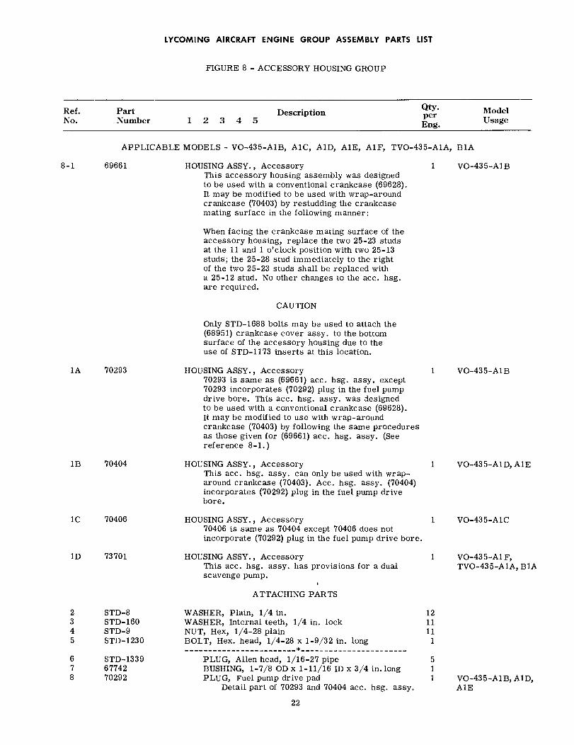
LYCOMING AIRCRAFT ENGINE GROUP ASSEMBLY PARTS LIST
FIGURE 8 - ACCESSORY HOUSING GROUP
Ref.No.
PartNumber
DescriptionQty.perEng.
ModelUsage1 2 3 4 5
APPLICABLE MODELS - VO-435-A1B, A1C, A1D, A1E, A1F, TVO-435-A1A, B1A
8-1 69661 HOUSING ASSY., AccessoryThis accessory housing assembly was designedto be used with a conventional crankcase (69628).It may be modified to be used with wrap-aroundcrankcase (70403) by restudding the crankcasemating surface in the following manner:
1 VO-435-A1B
When facing the crankcase mating surface of theaccessory housing, replace the two 25-23 studsat the 11 and 1 o'clock position with two 25-13studs; the 25-28 stud immediately to the rightof the two 25-23 studs shall be replaced witha 25-12 stud. No other changes to the acc. hsg.are required.
CAUTION
Only STD-1688 bolts may be used to attach the(68951) crankcase cover assy. to the bottomsurface of the accessory housing due to theuse of STD-1173 inserts at this location.
1A 70293
1B 70404
1C 70406
1D 73701
HOUSING ASSY., Accessory70293 is same as (69661) acc. hsg. assy. except70293 incorporates (70292) plug in the fuel pumpdrive bore. This acc. hsg. assy. was designedto be used with a conventional crankcase (69628).It may be modified to use with wrap-aroundcrankcase (70403) by following the same proceduresas those given for (69661) acc. hsg. assy. (Seereference 8-1.)
HOUSING ASSY., AccessoryThis acc. hsg. assy. can only be used with wrap-around crankcase (70403). Acc. hsg. assy. (70404)incorporates (70292) plug in the fuel pump drivebore.
HOUSING ASSY., Accessory70406 is same as 70404 except 70406 does notincorporate (70292) plug in the fuel pump drive bore.
HOUSING ASSY., AccessoryThis acc. hsg. assy. has provisions for a dualscavenge pump.
1 VO-435-A1B
1 VO-435-A1D, A1E
1 VO-435-A1C
1 VO-435-A1F,TVO-435-A1A, B1A
ATTACHING PARTS
2 STD-83 STD-1604 STD-95 STD-1230
6 STD-13397 677428 70292
WASHER, Plain, 1/4 in.WASHER, Internal teeth, 1/4 in. lockNUT, Hex, 1/4-28 plainBOLT, Hex. head, 1/4-28 x 1-9/32 in. long
PLUG, Allen head, 1/16-27 pipeBUSHING, 1-7/8 OD x 1-11/16 ID x 3/4 in. longPLUG, Fuel pump drive pad
Detail part of 70293 and 70404 acc. hsg. assy.
22
121111
1
511 VO-435-A1B, A1D,
A1E
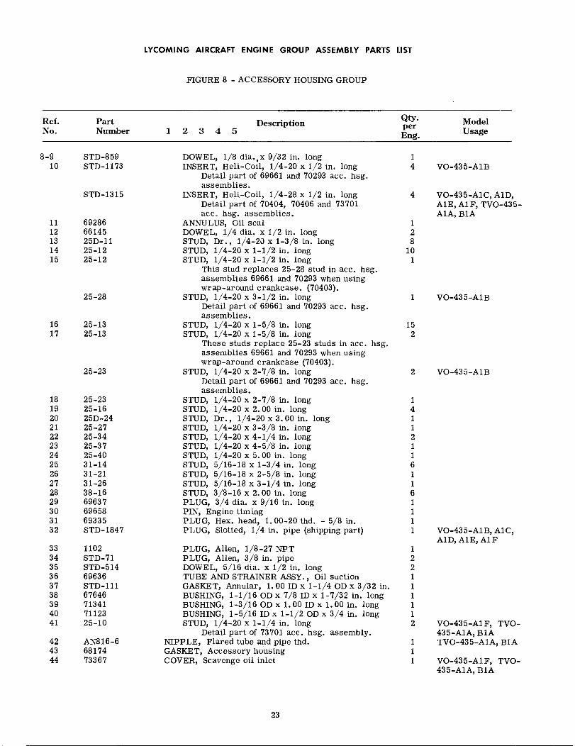
LYCOMING AIRCRAFT ENGINE GROUP ASSEMBLY PARTS LIST
FIGURE 8 - ACCESSORY HOUSING GROUP
Ref.No.
PartNumber
Description1 2 3 4 5
Qty.perEng.
ModelUsage
8-9 STD-85910 STD-1173
STD-1315
11 6928612 6614513 25D-1114 25-1215 25-12
25-28
16 25-1317 25-13
25-23
18 25-2319 25-1620 25D-2421 25-2722 25-3423 25-3724 25-4025 31-1426 31-2127 31-2628 38-1629 6963730 6965831 6933532 STD-1847
33 110234 STD-7135 STD-51436 6963637 STD-11138 6764639 7134140 7112341 25-10
42 AN816-643 6817444 73367
DOWEL, 1/8 dia.,x 9/32 in. longINSERT, Heli-Coil, 1/4-20 x 1/2 in. long
Detail part of 69661 and 70293 acc. hsg.assemblies.
INSERT, Heli-Coil, 1/4-28 x 1/2 in. longDetail part of 70404, 70406 and 73701acc. hsg. assemblies.
ANNULUS, Oil sealDOWEL, 1/4 dia. x 1/2 in. longSTUD, Dr., 1/4-20 x 1-3/8 in. longSTUD, 1/4-20 x 1-1/2 in. longSTUD, 1/4-20 x 1-1/2 in. long
This stud replaces 25-28 stud in ace. hsg.assemblies 69661 and 70293 when usingwrap-around crankcase. (70403).
STUD, 1/4-20 x 3-1/2 in. longDetail part of 69661 and 70293 acc. hsg.assemblies.
STUD, 1/4-20 x 1-5/8 in. longSTUD, 1/4-20 x 1-5/8 in. long
These studs replace 25-23 studs in acc. hsg.assemblies 69661 and 70293 when usingwrap-around crankcase (70403).
STUD, 1/4-20 x 2-7/8 in. longDetail part of 69661 and 70293 acc. hsg.assemblies.
STUD, 1/4-20 x 2-7/8 in. longSTUD, 1/4-20 x 2. 00 in. longSTUD, Dr., 1/4-20 x 3.00 in. longSTUD, 1/4-20 x 3-3/8 in. longSTUD, 1/4-20 x 4-1/4 in. longSTUD, 1/4-20 x 4-5/8 in. longSTUD, 1/4-20 x 5. 00 in. longSTUD, 5/16-18 x 1-3/4 in. longSTUD, 5/16-18 x 2-5/8 in. longSTUD, 5/16-18 x 3-1/4 in. longSTUD, 3/8-16 x 2.00 in. longPLUG, 3/4 dia. x 9/16 in. longPIN, Engine timingPLUG, Hex. head, 1.00-20 thd. - 5/8 in.PLUG, Slotted, 1/4 in. pipe (shipping part)
PLUG, Allen, 1/8-27 NPTPLUG, Allen, 3/8 in. pipeDOWEL, 5/16 dia. x 1/2 in. longTUBE AND STRAINER ASSY., Oil suctionGASKET, Annular, 1.00 ID x 1-1/4 OD x 3/32 in.BUSHING, 1-1/16 OD x 7/8 ID x 1-7/32 in. longBUSHING, 1-3/16 OD x 1.00 ID x 1.00 in. longBUSHING, 1-5/16 ID x 1-1/2 OD x 3/4 in. longSTUD, 1/4-20 x 1-1/4 in. long
Detail part of 73701 acc. hsg. assembly.NIPPLE, Flared tube and pipe thd.GASKET, Accessory housingCOVER, Scavenge oil inlet
14 VO-435-A1B
4 VO-435-A1C, A1D,A1E, A1F, TVO-435-A1A, B1A
128
101
1 VO-435-A1B
152
2 VO-435-A1B
141121161161111
122111112
111
VO-435-A1B, A1C,A1D,AlE, AF
VO-435-A1F, TVO-435-A1A, B1ATVO-435-A1A, B1A
VO-435-A1F, TVO-435-A1A, B1A
23
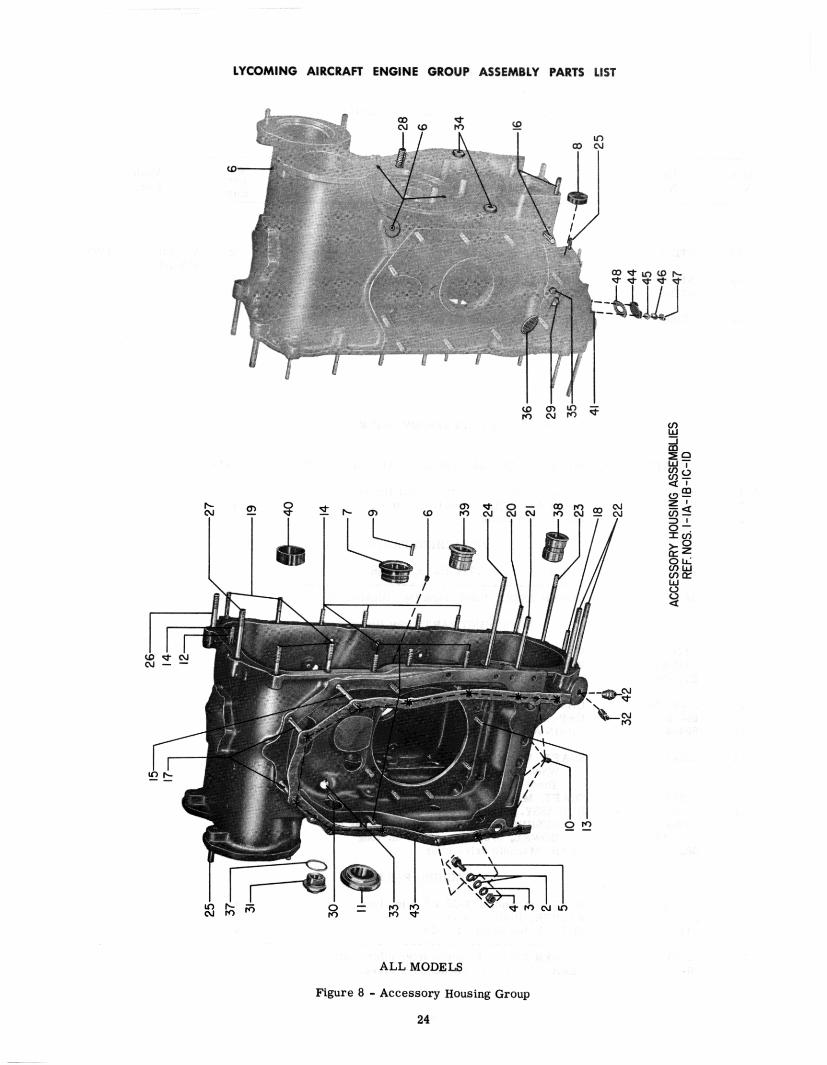

LYCOMING AIRCRAFT ENGINE GROUP ASSEMBLY PARTS LIST
FIGURE 8 - ACCESSORY HOUSING GROUP
Ref.No.
PartNumber
DescriptionQty.perEng.
ModelUsage1234 5
ATTACHING PARTS
8-45 STD-8
46 STD-16047 STD-9
48 73368
WASHER, Plain, 1/4 in.
WASHER, Internal teeth, 1/4 in. lockNUT, Hex. 1/4-28 plain
GASKET, Scavenge oil inlet adapter
FIGURE 9 - ACCESSORY DRIVES GROUP
APPLICABLE MODELS - VO-435-A1B, A1C, AID, A1E, A1F, TVO-435-A1A, B1A
9-123
676906917769645
WASHER, Generator drive gear thrustGEAR ASSEMBLY, Generator driveJAW, Hand crank
111
ATTACHING PARTS
4 STD-136
5 69568
CIRCLIP, Wire, .724 dia. x 1/16 in.
COVER ASSY., Hand crank (Not illustrated)
1
1
ATTACHING PARTS (Not illustrated)
6 STD-337 STD-6788 STD-596
9 AN4047-110 6981011 69494
12 68544
7238413 6856814 6856315 STD-1916 68553
WASHER, Plain, 3/8 in.WASHER, Internal teeth, 3/8 in. lockNUT, Plain, 3/8-24 x 21/64 in. thick
GASKET, Generator (Not illustrated)CAP ASSY., Hand crank (Not illustrated)CHAIN ASSY., Hand crank starting cap retainer (Not
illustrated)SHAFT, Magneto drive idler
When stock is exhausted; service with 72384.These shafts (68544 and 72384) are interchangeable.
SHAFT, Magneto drive idlerHUB ASSY., Magneto drive idler
BUSHING, Magneto drive idler gear hubDOWEL, 3/32 dia. x 7/32 in. long
GEAR, Magneto drive idler
666
111
1
11111
ATTACHING PARTS
17 AN10201018 STD-819 STD-43
20 6854521 68410
BOLT, Dr. end, 1/4-28 x 3/4 in. longWASHER, Plain, 1/4 in.NUT, Slotted shear, 1/4-28
WASHER ASSY., Magneto drive idler shaftGEAR ASSEMBLY, Tachometer driven
444
11
25

35
59
I 32
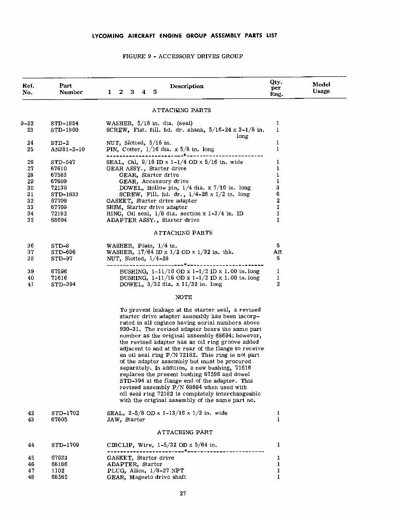
LYCOMING AIRCRAFT ENGINE GROUP ASSEMBLY PARTS LIST
FIGURE 9 - ACCESSORY DRIVES GROUP
Ref.No.
PartNumber
DescriptionQty.perEng.
ModelUsage1 2 3 4 5
ATTACHING PARTS
9-22 STD-185423 STD-1860
24 STD-225 AN381-2-10
26 STD-54727 6761028 6758329 6760930 7213931 STD-183332 6770833 6770934 7218235 68694
WASHER, 5/16 in. dia. (seal)SCREW, Flat. fill. hd. dr. shank, 5/16-24 x 3-1/8 in.
longNUT, Slotted, 5/16 in.PIN, Cotter, 1/16 dia. x 5/8 in. long
SEAL, Oil, 9/16 ID x 1-1/4 OD x 5/16 in. wideGEAR ASSY., Starter drive
GEAR, Starter driveGEAR, Accessory driveDOWEL, Hollow pin, 1/4 dia. x 7/16 in. longSCREW, Fill. hd. dr., 1/4-28 x 1/2 in. long
GASKET, Starter drive adapterSHIM, Starter drive adapterRING, Oil seal, 1/8 dia. section x 1-3/4 in. IDADAPTER ASSY., Starter drive
11
11
1111362111
ATTACHING PARTS
36 STD-837 STD-69638 STD-97
39 6759640 7161641 STD-394
WASHER, Plain, 1/4 in.WASHER, 17/64 ID x 1/2 OD x 1/32 in. thk.NUT, Slotted, 1/4-28
BUSHING, 1-11/16 OD x 1-1/2 ID x 1.00 in. longBUSHING, 1-11/16 OD x 1-1/2 ID x 1.00 in. longDOWEL, 3/32 dia. x 11/32 in. long
6AR
6
112
NOTE
To prevent leakage at the starter seal, a revisedstarter drive adapter assembly has been incorp-rated in all engines having serial numbers above920-31. The revised adapter bears the same partnumber as the original assembly 68694; however,the revised adapter has an oil ring groove addedadjacent to and at the rear of the flange to receivean oil seal ring P/N 72182. This ring is not partof the adapter assembly but must be procuredseparately. In addition, a new bushing, 71616replaces the present bushing 67596 and dowelSTD-394 at the flange end of the adapter. Thisrevised assembly P/N 68694 when used withoil seal ring 72182 is completely interchangeablewith the original assembly of the same part no.
42 STD-170243 67605
SEAL, 2-5/8 OD x 1-13/16 x 1/2 in. wideJAW, Starter
11
ATTACHING PART
44 STD-1709
45 6763346 6818647 110248 68565
CIRCLIP, Wire, 1-5/32 OD x 5/64 in.
GASKET, Starter driveADAPTER, StarterPLUG, Allen, 1/8-27 NPTGEAR, Magneto drive shaft
1111
27
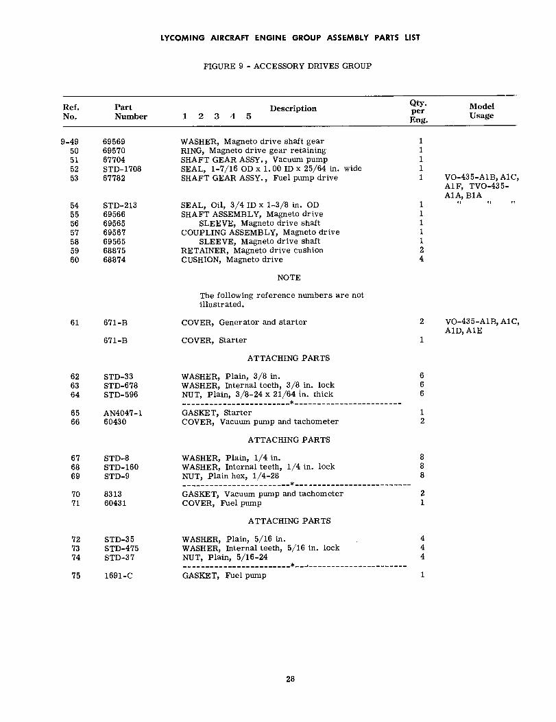
LYCOMING AIRCRAFT ENGINE GROUP ASSEMBLY PARTS LIST
FIGURE 9 - ACCESSORY DRIVES GROUP
Ref.No.
PartNumber
DescriptionQty.perEng.
ModelUsage1 2 3 4 5
9-4950515253
695696957067704STD-170867782
WASHER, Magneto drive shaft gearRING, Magneto drive gear retainingSHAFT GEAR ASSY., Vacuum pumpSEAL, 1-7/16 OD x 1.00 ID x 25/64 in. wideSHAFT GEAR ASSY., Fuel pump drive
11111 VO-435-A1B, A1C,
A1F, TVO-435-A1A, B1A
54 STD-21355 6956656 6956557 6956758 6956559 6887560 68874
SEAL, Oil, 3/4 ID x 1-3/8 in. ODSHAFT ASSEMBLY, Magneto drive
SLEEVE, Magneto drive shaftCOUPLING ASSEMBLY, Magneto drive
SLEEVE, Magneto drive shaftRETAINER, Magneto drive cushionCUSHION, Magneto drive
1111124
NOTE
The following reference numbers are notillustrated.
61 671-B
671-B
COVER, Generator and starter 2 VO-435-A1B, A1C,A1D, A1E
1COVER, Starter
ATTACHING PARTS
62 STD-3363 STD-67864 STD-596
65 AN4047-166 60430
WASHER, Plain, 3/8 in.WASHER, Internal teeth, 3/8 in. lockNUT, Plain, 3/8-24 x 21/64 in. thick
GASKET, StarterCOVER, Vacuum pump and tachometer
666
12
ATTACHING PARTS
67 STD-868 STD-16069 STD-9
70 831371 60431
WASHER, Plain, 1/4 in.WASHER, Internal teeth, 1/4 in. lockNUT, Plain hex, 1/4-28
GASKET, Vacuum pump and tachometerCOVER, Fuel pump
888
21
ATTACHING PARTS
72 STD-3573 STD-47574 STD-37
75 1691-C
WASHER, Plain, 5/16 in.WASHER, Internal teeth, 5/16 in. lockNUT, Plain, 5/16-24
GASKET, Fuel pump
444
1
28
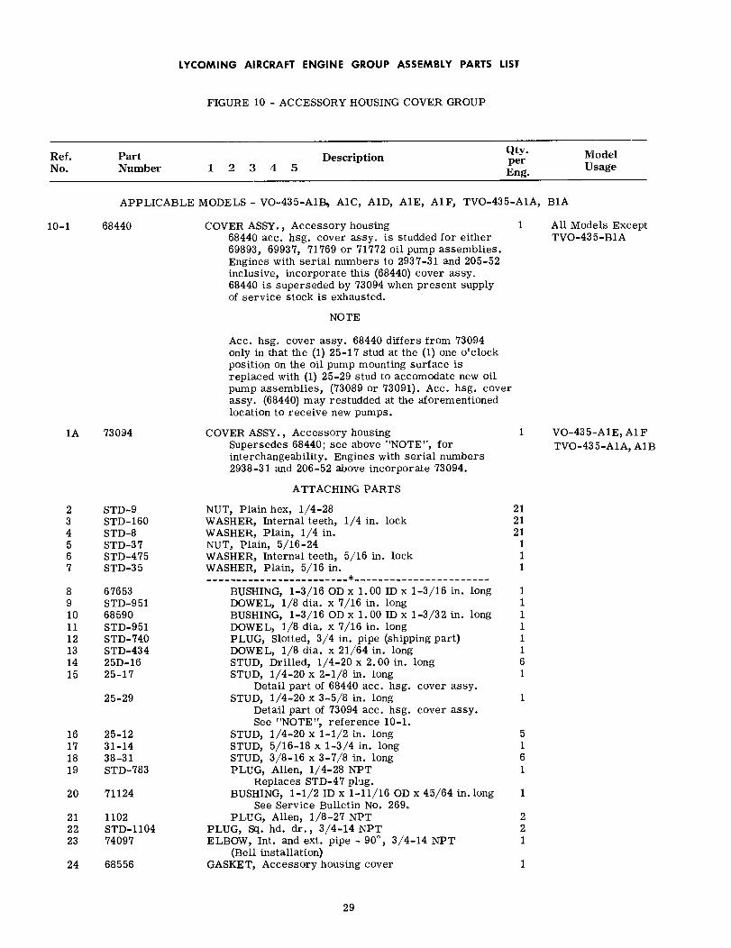
LYCOMING AIRCRAFT ENGINE GROUP ASSEMBLY PARTS LIST
FIGURE 10 - ACCESSORY HOUSING COVER GROUP
Ref.No.
PartNumber
DescriptionQty.perEng.
ModelUsage1 2 3 4 5
APPLICABLE MODELS - VO-435-A1B, A1C, A1D, A1E, A1F, TVO-435-A1A, B1A
10-1 68440 COVER ASSY., Accessory housing68440 acc. hsg. cover assy. is studded for either69893, 69937, 71769 or 71772 oil pump assemblies.Engines with serial numbers to 2937-31 and 205-52inclusive, incorporate this (68440) cover assy.68440 is superseded by 73094 when present supplyof service stock is exhausted.
1 All Models ExceptTVO-435-B1A
NOTE
Ace. hsg. cover assy. 68440 differs from 73094only in that the (1) 25-17 stud at the (1) one o'clockposition on the oil pump mounting surface isreplaced with (1) 25-29 stud to accomodate new oilpump assemblies, (73089 or 73091). Ace. hsg. coverassy. (68440) may restudded at the aforementionedlocation to receive new pumps.
COVER ASSY., Accessory housingSupersedes 68440; see above "NOTE", forinterchangeability. Engines with serial numbers2938-31 and 206-52 above incorporate 73094.
ATTACHING PARTS
1A 73094 1 VO-435-A1E,A1FTVO-435-A1A, A1B
2 STD-93 STD-1604 STD-85 STD-376 STD-4757 STD-35
8 676539 STD-95110 6859011 STD-95112 STD-74013 STD-43414 25D-1615 25-17
25-29
16 25-1217 31-1418 38-3119 STD-783
20 71124
21 110222 STD-110423 74097
24 68556
NUT, Plain hex, 1/4-28WASHER, Internal teeth, 1/4 in. lockWASHER, Plain, 1/4 in.NUT, Plain, 5/16-24WASHER, Internal teeth, 5/16 in. lockWASHER, Plain, 5/16 in.
BUSHING, 1-3/16 OD x 1.00 ID x 1-3/16 in. longDOWEL, 1/8 dia. x 7/16 in. longBUSHING, 1-3/16 OD x 1.00 ID x 1-3/32 in. longDOWEL, 1/8 dia. x 7/16 in. longPLUG, Slotted, 3/4 in. pipe (shipping part)DOWEL, 1/8 dia. x 21/64 in. longSTUD, Drilled, 1/4-20 x 2.00 in. longSTUD, 1/4-20 x 2-1/8 in. long
Detail part of 68440 acc. hsg. cover assy.STUD, 1/4-20 x 3-5/8 in. long
Detail part of 73094 acc. hsg. cover assy.See "NOTE", reference 10-1.
STUD, 1/4-20 x 1-1/2 in. longSTUD, 5/16-18 x 1-3/4 in. longSTUD, 3/8-16 x 3-7/8 in. longPLUG, Allen, 1/4-28 NPT
Replaces STD-47 plug.BUSHING, 1-1/2 ID x 1-11/16 OD x 45/64 in. long
See Service Bulletin No. 269.PLUG, Allen, 1/8-27 NPT
PLUG, Sq. hd. dr., 3/4-14 NPTELBOW, Int. and ext. pipe - 90° , 3/4-14 NPT
(Bell installation)GASKET, Accessory housing cover
212121
111
11111161
1
5161
1
221
1
29

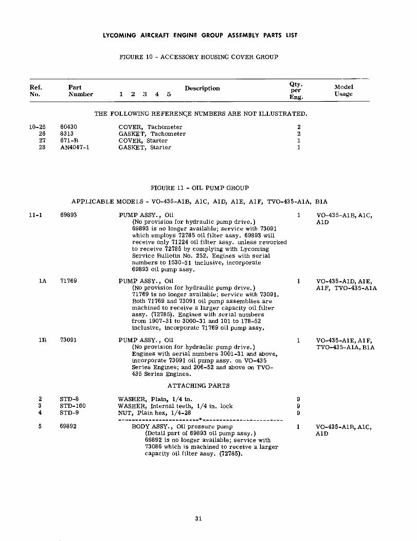
LYCOMING AIRCRAFT ENGINE GROUP ASSEMBLY PARTS LIST
FIGURE 10 - ACCESSORY HOUSING COVER GROUP
Ref.No.
PartNumber
DescriptionQty.perEng.
ModelUsage1 2 3 4 5
THE FOLLOWING REFERENCE NUMBERS ARE NOT ILLUSTRATED.
10-25262728
604308313671-BAN4047-1
COVER, TachometerGASKET, TachometerCOVER, StarterGASKET, Starter
2211
FIGURE 11 - OIL PUMP GROUP
APPLICABLE MODELS - VO-435-A1B, A1C, A1D, A1E, A1F, TVO-435-A1A, B1A
11-1 69893
1A 71769
1B 73091
PUMP ASSY., Oil(No provision for hydraulic pump drive. )69893 is no longer available; service with 73091which employs 72785 oil filter assy. 69893 willreceive only 71224 oil filter assy. unless reworkedto receive 72785 by complying with LycomingService Bulletin No. 252. Engines with serialnumbers to 1530-31 inclusive, incorporate69893 oil pump assy.
PUMP ASSY., Oil(No provision for hydraulic pump drive.)71769 is no longer available; service with 73091.Both 71769 and 73091 oil pump assemblies aremachined to receive a larger capacity oil filterassy. (72785). Engines with serial numbersfrom 1907-31 to 3000-31 and 101 to 178-52inclusive, incorporate 71769 oil pump assy.
PUMP ASSY., Oil(No provision for hydraulic pump drive. )Engines with serial numbers 3001-31 and above,incorporate 73091 oil pump assy. on VO-435Series Engines; and 206-52 and above on TVO-435 Series Engines.
ATTACHING PARTS
1 VO-435-A1B, A1C,AID
1 VO-435-A1D, A1E,A1F, TVO-435-A1A
1 VO-435-A1E,A1F,TVO-435-A1A, B1A
2 STD-83 STD-1604 STD-9
5 69892
WASHER, Plain, 1/4 in.WASHER, Internal teeth, 1/4 in. lockNUT, Plain hex, 1/4-28
BODY ASSY., Oil pressure pump(Detail part of 69893 oil pump assy.)69892 is no longer available; service with73086 which is machined to receive a largercapacity oil filter assy. (72785).
999
1 VO-435-A1B, A1C,AID
31
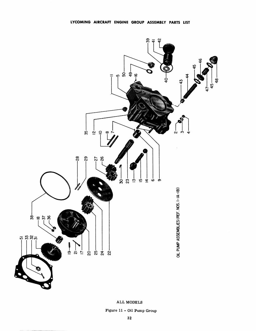

LYCOMING AIRCRAFT ENGINE GROUP ASSEMBLY PARTS LIST
FIGURE 11 - OIL PUMP GROUP
Ref.No.
PartNumber
Description1 2 3 4 5
Qty.perEng.
ModelUsage
11-5 71770 BODY ASSY., Oil pressure pump(Detail part of 71769 oil pump assy.)71770 is no longer available; service with73086 which is machined to receive a largercapacity oil filter assy. (72785).
NOTE
1 VO-435-A1D, A1E,A1F, TVO-435-A1A
If 69892 or 71770 oil pressure pump bodyassemblies need be replaced with 73086,the accessory housing cover assy. (68440)which they require, must be modified byreplacing the 25-17 stud at the one o'clockposition on the oil pump mounting surfacewith a 25-29 stud.
73086
6 684667 STD-3948 25D-219 25D-2410 25D-2511 6847312 STD-139213 7199914 1028-B15 73761
16 MS12220017 6961818 6846619 STD-39420 6816121 AN381-4-2022 6846823 6960524 6642625 6840326 6129727 6840428 6964729 6776230 AN280H40631 6846732 STD-6133 STD-6034 STD-740
35 STD-7136 STD-837 STD-4338 AN12390839 AN900-2840 70460
BODY ASSY., Oil pressure pump(Detail part of 73091 oil pump assy.)Provision for 3/4-14 NPT hole and 4-boltflange connection at oil inlet location.Requires acc. hsg. cover assy. 73094.BUSHING, Oil pump drive shaftDOWEL, 3/32 dia. x 11/32 in. longSTUD, 1/4-20 x 2-5/8 in. longSTUD, 1/4-20 x 3.00 in. longSTUD, 1/4-20 x 3-1/8 in. longSLEEVE, Oil relief valvePLUG, . 268-. 269 dia. x 5/16 in. longRETAINER, Ball check valveBALL, 11/16 in. dia.SPRING, Check valve
Supersedes and interchangeable with654-B.
INSERT, Heli-Coil, #10-24 x 31/64 in. longBODY ASSY., Oil scavenge pump
BUSHING, Oil pump drive shaftDOWEL, 3/32 dia. x 11/32 in. longSHAFT, Oil pump idler, longPIN, Cotter, 1/8 dia. x 1-1/4 in. long
SPACER, Oil pressure and scavenge pumpSHAFT, Oil pumpIMPELLER, Oil scavenge pump, drivingIMPELLER, Oil scavenge pump, drivenIMPELLER, Oil pressure pump, drivingIMPELLER, Oil pressure pump, drivenDOWEL, Oil pump, longDOWEL, Oil pumpKEY, Woodruff, 1/8-3/4 in. dia.GEAR, Oil pressure and scavenge pumpNUT, Slotted shear, 1/2-20PIN, Cotter, 3/32 dia. x 1.00 in. longPLUG, Slotted, 3/4 in. pipe (shipping part; Not
illustrated)PLUG, Allen head, 3/8 in. pipeWASHER, Plain, 1/4 in.NUT, Slotted shear, 1/4-28
RING, Oil seal, 4-3/4 ID x 1/8 in. dia. sectionGASKET, Copper-asbestos, 1-3/4 ID x 3/32 in. thickWASHER, Oil filter assy.
1 VO-435-A1E,A1F,TVO-435-A1A, B1A
1122211111
4111111111111111111
1662111
33
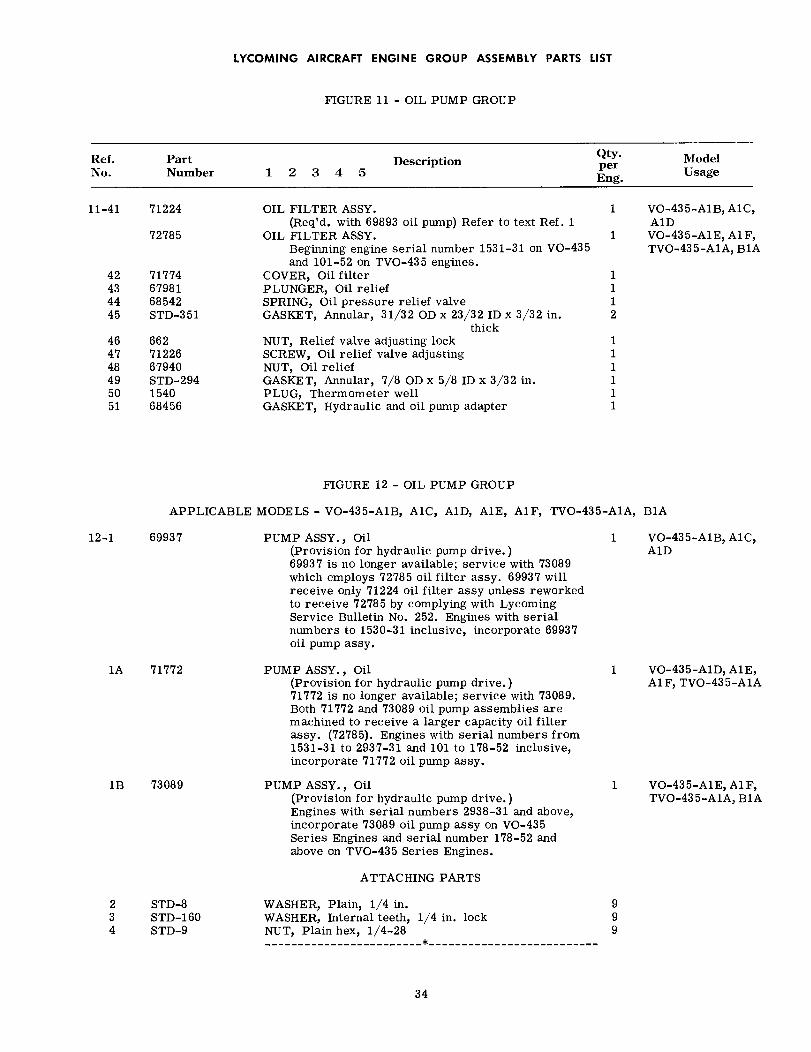
LYCOMING AIRCRAFT ENGINE GROUP ASSEMBLY PARTS LIST
FIGURE 11 - OIL PUMP GROUP
Ref.No.
PartNumber
Description1 2 3 4 5
Qty.perEng.
ModelUsage
11-41 71224
72785
42 7177443 6798144 6854245 STD-351
46 66247 7122648 6794049 STD-29450 154051 68456
OIL FILTER ASSY.(Req'd. with 69893 oil pump) Refer to text Ref. 1
OIL FILTER ASSY.Beginning engine serial number 1531-31 on VO-435and 101-52 on TVO-435 engines.
COVER, Oil filterPLUNGER, Oil reliefSPRING, Oil pressure relief valveGASKET, Annular, 31/32 OD x 23/32 ID x 3/32 in.
thickNUT, Relief valve adjusting lockSCREW, Oil relief valve adjustingNUT, Oil reliefGASKET, Annular, 7/8 OD x 5/8 ID x 3/32 in.PLUG, Thermometer wellGASKET, Hydraulic and oil pump adapter
1 VO-435-A1B,A1C,A1D
1 VO-435-A1E, A1F,TVO-435-A1A, B1A
1112
111111
FIGURE 12 - OIL PUMP GROUP
APPLICABLE MODELS - VO-435-A1B, A1C, A1D, A1E, A1F, TVO-435-A1A, B1A
12-1 69937
1A 71772
1B 73089
PUMP ASSY., Oil(Provision for hydraulic pump drive. )69937 is no longer available; service with 73089which employs 72785 oil filter assy. 69937 willreceive only 71224 oil filter assy unless reworkedto receive 72785 by complying with LycomingService Bulletin No. 252. Engines with serialnumbers to 1530-31 inclusive, incorporate 69937oil pump assy.
PUMP ASSY., Oil(Provision for hydraulic pump drive.)71772 is no longer available; service with 73089.Both 71772 and 73089 oil pump assemblies aremachined to receive a larger capacity oil filterassy. (72785). Engines with serial numbers from1531-31 to 2937-31 and 101 to 178-52 inclusive,incorporate 71772 oil pump assy.
PUMP ASSY., Oil(Provision for hydraulic pump drive. )Engines with serial numbers 2938-31 and above,incorporate 73089 oil pump assy on VO-435Series Engines and serial number 178-52 andabove on TVO-435 Series Engines.
1 VO-435-A1B, A1C,AID
1 VO-435-A1D, A1E,A1F, TVO-435-A1A
1 VO-435-A1E,A1F,TVO-435-A1A, B1A
ATTACHING PARTS
2 STD-83 STD-1604 STD-9
WASHER, Plain, 1/4 in.WASHER, Internal teeth, 1/4 in. lockNUT, Plain hex, 1/4-28
999
34

LYCOMING AIRCRAFT ENGINE GROUP ASSEMBLY PARTS LIST
FIGURE 12 - OIL PUMP GROUP
Ref.No.
PartNumber
DescriptionQty.perEng.
ModelUsage1 2 3 4 5
12-5 69938
71771
BODY ASSY., Oil'pressure pump(Detail part of 69937 oil pump assy.)69938 is no longer available; service with73088 which is machined to receive a largercapacity oil filter assy. (72785).
BODY ASSY., Oil pressure pump(Detail part of 71772 oil pump assy.)71771 is no longer available; service with73088 which is machined to receive alarger capacity oil filter assy. (72785).
1 VO-435-A1B,A1C,AID
1 VO-435-A1D, A1E,A1F, TVO-435-A1A
NOTE
If 69938 or 71771 oil pressure pump bodyassemblies need be replaced with 73088, theaccessory housing cover assy. (68440) whichthey require, must be modified by replacingthe 25-17 stud at the one o'clock position onthe oil pump mounting surface with a 25-29stud.
73088
6 684667 STD-3948 MS1222009 25D-2110 25D-2411 25D-2512 31-1213 31-1414 STD-116415 6847316 STD-139217 7199918 1028-B19 73761
20 6961821 6846622 STD-39423 6816124 AN381-4-2025 6846826 6967127 6642628 6840329 6129730 6840431 6964732 6776233 AN280H40634 6846735 STD-61
BODY ASSY., Oil pressure pump(Detail part of 73089 oil pump assy.)Provision for 3/4-14 NPT hole and 4-boltflange connection at oil inlet location. Requiresacc. hsg. cover assy. 73094.BUSHING, Oil pump drive shaftDOWEL, 3/32 dia. x 11/32 in. longINSERT, Heli-Coil, #10-24 x 31/64 in. longSTUD, 1/4-20 x 2-5/8 in. longSTUD, 1/4-20 x 3.00 in. longSTUD, 1/4-20 x 3-1/8 in. longSTUD, 5/16-18 x 1-1/2 in. longSTUD, 5/16-18 x 1-3/4 in. longINSERT, Heli-Coil, 5/16-18 x 5/8 in. longSLEEVE, Oil relief valvePLUG, . 268-. 269 dia. x 5/16 in. longRETAINER, Ball check valveBALL, 11/16 in. dia.SPRING, Check valve
Supersedes and interchangeable with654-B.
BODY ASSY., Oil scavenge pumpBUSHING, Oil pump drive shaftDOWEL, 3/32 dia. x 11/32 in. longSHAFT, Oil pump idler, longPIN, Cotter, 1/8 dia. x 1-1/4 in. long
SPACER, Oil pressure and scavenge pumpSHAFT, Oil pumpIMPELLER, Oil scavenge pump, drivingIMPELLER, Oil scavenge pump, drivenIMPELLER, Oil pressure pump, drivingIMPELLER, Oil pressure pump, drivenDOWEL, Oil pump longDOWEL, Oil pumpKEY, Woodruff, 1/8 x 3/4 in. dia.GEAR, Oil pressure and scavenge pumpNUT, Slotted shear, 1/2-20
1 VO-435-A1E,A1F,TVO-435-A1A, B1A
11422213111111
1111111111111111
35

2.9
27

LYCOMING AIRCRAFT ENGINE GROUP ASSEMBLY PARTS LIST
FIGURE 12 - OIL PUMP GROUP
Description1 2 3 4 5
Ref.No.
PartNumber
Qty.perEng.
ModelUsage
12-36 STD-6037 STD-740
38 STD-7139 STD-840 STD-4341 AN12390842 AN900-2843 STD-20844 7046045 71224
72785
46 7177447 6798148 6854249 STD-35150 66251 7122652 6794053 STD-29454 154055 68456
PIN, Cotter, 3/32 dia. x 1.00 in. longPLUG, Slotted, 3/4 in. pipe (shipping part) Not
illustratedPLUG, Allen head, 3/8 in. pipeWASHER, Plain, 1/4 in.NUT, Slotted shear, 1/4-28
RING, Oil seal, 4-3/4 ID x 1/8 in. dia. sectionGASKET, Copper, asbestos, 1-3/4 ID x 3/32 in. thickSEAL, Oil, 7/8 ID x 1-1/2 OD x 5/16 in. wideWASHER, Oil filter assy.OIL FILTER ASSY.
(Req'd. with 69937 oil pump) Refer to text, ref. 1.OIL FILTER ASSY.
Beginning engine serial number 1531-31 on VO-435 and 101-52 on TVO-435 engines.
COVER, Oil filterPLUNGER, Oil reliefSPRING, Oil pressure relief valveGASKET, Annular, 31/32 OD x 23/32 ID x 3/32 in. thickNUT, Relief valve adjusting lockSCREW, Oil relief valve adjustingNUT, Oil reliefGASKET, Annular, 7/8 OD x 5/8 ID x 3/32 in.PLUG, Thermometer wellGASKET, Hydraulic and oil pump adapter
11
16621111 VO-435-A1B, A1C,
A1D1 VO-435-A1E, A1F,
TVO-435-A1A, B1A
1112111111
THE FOLLOWING REFERENCE NUMBERS ARE NOT ILLUSTRATED
56 72412 COVER, Hydraulic pump 1
ATTACHING PARTS
57 STD-3558 STD-47559 STD-37
60 20415
WASHER, Plain, 5/16 in.WASHER, Internal teeth, 5/16 in. lockNUT, Plain, 5/16-24
GASKET, Hydraulic pump
444
1
37

71437
LYCOMING AIRCRAFT ENGINE GROUP ASSEMBLY PARTS LIST
FIGURE 13 - MAGNETOS AND MAGNETO DRIVE GROUP
Ref.No.
PartNumber
DescriptionQty.perEng.
ModelUsage1 2 3 4 5
APPLICABLE MODELS - VO-435-A1B, A1C, A1D, A1E, A1F, TVO-435-A1A, B1A
13-1 71436 MAGNETO(Same as Bendix-Scintilla No. 10-51365-33,Type S6LN-20) Supersedes and interchangeablewith 69606. Magneto 71436 does not conform toMIL. Specification AN-I-27.
1 VO-435-A1B,A1C,A1D
NOTE
Supersedure was made to provide for a strongerrotor shaft and an improved breaker assembly.New rotor shaft has a magnet capable ofreceiving a full charge without requiring thecharge to be knocked down.
MAGNETO(Same as Bendix-Scintilla No. 10-52350-22,Type S6LN-22). 71437 meets the radio inter-ference requirements of MIL. Spec. AN-I-27.
1
2 71435
71438
3 72038
4 71163
74174
MAGNETO, Impulse coupling(Same as Bendix-Scintilla No. 10-51365-34,Type S6RN-21). Supersedes and interchangeablewith 69607. Magneto 71435 does not conform toMIL. Specification AN-I-27. The above "NOTE",reference 13-1, also applies to 71435 magneto.
MAGNETO, Impulse coupling(Same as Bendix-Scintilla No. 10-52350-23,Type S6RN-23). 71438 meets the radio inter-ference requirements of MIL. Spec. AN-I-27.
MAGNETO(Same as Bendix-Scintilla No. 10-163050-1,Type S6LN-204.)
MAGNETORetard Breaker (retard angle 30°)(Scintilla P/N 10-163010-1) Superseded by 74174beginning engine serial No. 3031-31 and 220-52.
MAGNETO, Retard breaker (Retard angle 25 ° )(Same as Bendix Scintilla No. 10-163010-15,Type S6RN-200). Magneto 74174 supersedesand replaces 71163 to improve the starting ofvertical engines.
1
1
1 VO-435-A1E, A1F,TVO-435-A1A, B1A
ATTACHING PARTS
5 STD-17276 STD-4757 STD-37
8 62224
9 69208
9A 69208
10 68875
WASHER, Plain, 3/4 OD x 11/32 ID x 1/8 in. thk.WASHER, Internal teeth, 5/16 in. lockNUT, Plain, 5/16-24
GASKET, MagnetoReplaces 45663.
COUPLING, Magneto drive(Required with magnetos, 71436 and 71437.)
COUPLING, Magneto drive(Required with magnetos 72038 and 74174.)
RETAINER, Magneto drive cushion
444
2
1 VO-435-A1B,A1C,A1D
2 VO-435-AE, A1F,TVO-435-A1A, B1A
2
38

LYCOMING AIRCRAFT ENGINE GROUP ASSEMBLY PARTS LIST
FIGURE 13 - MAGNETOS AND MAGNETO DRIVE GROUP
Ref.No.
PartNumber
DescriptionQty.perEng.
ModelUsage1 2 3 4 5
13-11 68874 CUSHION, Magneto drive
ATTACHING PARTS
4
12 10-4093
12A 10-4093
13 10-4092
WASHER(Required with magnetos,
WASHER(Required with magnetos,
NUT
71436 and 71437.)
74174 and 72038.)
(Required with magnetos, 71436 and 71437.)NUT13A 10-163151
14 10-90751-19
14A 10-90751-19
15 61566
15A 70497
16 71574
17 71571
(Required with magnetos,PIN, Cotter
(Required with magnetos,PIN, Cotter
(Required with magnetos,
74174 and 72038.)
71436 and 71437.)
74174 and 72038.)
1 VO-435-A1B,A1C,A1D
2 VO-435-A1E, A1F,TVO-435-A1A, B1A
1 VO-435-A1B,A1C,A1D
2 VO-435-A1E, A1F,TVO-435-A1A, B1A
1 VO-435-A1B,A1C,A1D
2 VO-435-A1E, AF,TVO-435-A1A, B1A
2 VO-435-A1B,A1C,A1D
2
2 VO-435-A1E, A1F,TVO-435-A1A, B1A
KIT ASSY., Magneto ground terminal(Same as Bendix-Scintilla P/N 10-52305-1.)Procurable as an assembly only.Required with magnetos, 71435 and 71436.
KIT ASSY., Magneto ground terminal(Same as Bendix-Scintilla P/N 10-52306.)Procurable as an assembly only.Required with magnetos, 71437 and 71438.
KIT, Magneto ground terminal(Required with magnetos, 74174 and 72038.)
KIT, Magneto retard terminal(Required with magneto, 74174.)
39


LYCOMING AIRCRAFT ENGINE GROUP ASSEMBLY PARTS LIST
FIGURE 14 - ACCESSORY DRIVE GEAR AND ADAPTER GROUP
Ref.No.
PartNumber
DescriptionQty.perEng.
ModelUsage1 2 3 4 5
APPLICABLE MODELS - VO-435-A1B, A1C, A1D, A1E, A1F, TVO-435-A1A, B1A
14-1 67639 ADAPTER, Accessory drive shaft 1
ATTACHING PARTS
2 STD-83 STD-97
4 676385 303116 STD-16987 688358 676429 67641
WASHER, Plain, 1/4 in.NUT, Slotted, 1/4-28
SHIM, Accessory drive shaft adapterBEARING, Accessory drive gearRING, Internal-retaining, 2-5/8 dia. x 5/64 in. thickGEAR, Accessory driveLOCKWASHER, Accessory drive shaftNUT, Accessory drive shaft
88
111111
41

4 I

LYCOMING AIRCRAFT ENGINE GROUP ASSEMBLY PARTS LIST
FIGURE 15 - OIL SUMP AND RELATED PARTS GROUP
Ref.No.
PartNumber
DescriptionQty.perEng.
ModelUsage1 2 3 4 5
APPLICABLE MODELS - VO-435-A1B, A1C, A1D, A1E, A1F, TVO-435-A1A, B1A
15-1 70319 SUMP ASSY., OilSupersedes and interchangeable with 69756.
1 VO-435-A1B
NOTE
The difference between the two assemblies isas follows; The six mounting pad studs on69756 are 31-12, whereas the studs on 70319,part number 31-14 are 1/4 inch longer, 69756oil sump is made from aluminum casting,whereas 70319 is made from magnesiumcasting.
2 71142
73705
SUMP ASSY., Oil 1 VO-435-A1C, A1D,A1E
1 VO-435-A1F,TVO-435-A1A, B1A
SUMP ASSY., Oil
ATTACHING PARTS
3 STD-84 STD-1605 STD-9
6 31-12
31-14
7 MS124777
8 STD-111
8A AN6290-12
9 69335
9A MS9015-12
10 AN912-7D
73671
11 69663
WASHER, Plain, 1/4 in.WASHER, Internal teeth, 1/4 in. lockNUT, Plain, 1/4 in.
STUD, 5/16-18 x 1-1/2 in. longDetail part of 69756 oil sump assy.
STUD, 5/16-18 x 1-3/4 in. longDetail part of 70319 oil sump assy.
INSERT, Heli-Coil, 5/16-24 x 25/32 in. longDetail part of 71142 and 73705 oil sumpassemblies
GASKET, Annular, 1.00 ID x 1-1/4 OD x 3/32 in.STD-111 gasket along with 69335 plug is requiredat oil drain hole location in 70319 oil sump assy.
SEAL, 59/64 ID x 7/64 in. dia. sectionAN6290-12 seal along with MS9015-12 plug isrequired at oil drain hole location in 71142 and73705 oil sump assemblies.
PLUG, Hex head, 1.00-20 thd. x 5/8 in. long69335 plug along with STD-111 gasket is requiredat oil drain hole location in 70319 oil sump assy.
PLUG, Hex., 1-1/16-12 thd.MS9015-12 plug along with AN6290-12 seal isrequired at oil drain hole location in 71142 and73705 oil sump assemblies.
BUSHING, Reducer, 3/4 to 1/2 in. pipeRequired at oil drain-back hole location in 73705oil sump assy.
TEE, Turbocharger oil drainRequired at oil drain-back hole location in 73705oil sump assy.
TUBE, Rocker box drain (right) (Not illustrated)Requires STD-1576 hose. Tube 69663 is no longeravailable. If replacement is necessary, servicewith 71702 tube and 72045 hose.
111111
6 VO-435-A1B
6
13 VO-435-A1C, A1D,A1E, A1F, TVO-435-A1A, B1A
1 VO-435-A1B
1 VO-435-A1C, AID,AlE, AF, TVO-435-A1A, B1A
1 VO-435-A1B
1 VO-435-A1C, AD,A1E, A1F, TVO-435-A1A, B1A
1 VO-435-A1F
1 TVO-435-A1A, B1A
1 VO-435-A1B,A1C,A1D
43


LYCOMING AIRCRAFT ENGINE GROUP ASSEMBLY PARTS LIST
FIGURE 15 - OIL SUMP AND RELATED PARTS GROUP
Ref.No.
PartNumber
DescriptionQty.perEng.
ModelUsage1 2 3 4 5
15-11 71203
71702
12 69664
71204
71702
13 STD-1793
TUBE, Rocker box drain (right) (Not illustrated)Requires STD-1576 hose. Tube 71203 is nolonger available. If replacement is necessary,service with 71702 tube and 72045 hose.
TUBE, Rocker box drainRequires 73731 (left) hose and 72045 (right) hose.
TUBE, Rocker box drain (left) (Not illustrated)Requires STD-1576 hose. Tube 69664 is nolonger available. If replacement is necessary,service with 71702 tube and 73731 hose.
TUBE, Rocker box drain (left) (Not illustrated)Requires STD-1576 hose. Tube 71204 is nolonger available. If replacement is necessary,service with 71702 tube and 73731 hose.
TUBE, Rocker box drainRequires 73731 (left) hose and 72045 (right)hose.
HOSE, 3/8 ID x 1-21/32 in. long
1 VO-435-A1C, A1D,A1E
1 VO-435-A1D, A1E,A1F, TVO-435-A1A,B1A
1 VO-435-AB, A1C,A1D
1 VO-435-A1C, A1D,A1E
1 VO-435-A1D, A1E,A1F, TVO-435-A1A,B1A
6
ATTACHING PARTS
14 STD-1252
15 AN840-10D
16 STD-1576
17 73731
18 72045
CLAMP, Hose, 11/16 ID x 1/2 in. wide
ADAPTER, Hose to pipe thd., 1/2 pipe x 5/8 in. dia.hose
HOSE, 5/8 ID x 31/32 OD x 2-1/2 in. long (left andright)
Required with rocker box drain tubes 69663,69664, 71203 and 71204 (Not Illustrated).
HOSE, Rocker box drain tube, cylinder 2-4-6 (Left)Supersedes 71703
HOSE, Rock box drain tube, cylinder 1-3-5 (Right)Supersedes 71703.
12
2
2 VO-435-A1C, A1D,A1E
1 VO-435-A1D, A1E,A1F, TVO-435-A1A, B1A
ATTACHING PARTS
19 STD-1640
20 72437
CLAMP, Hose, 15/16 ID x 1/2 in. wide
GASKET, Oil sumpReplaces 69657.
4
1
45
LYCOMING AIRCRAFT ENGINE GROUP ASSEMBLY PARTS LIST
Ref.No.
PartNumber
DescriptionQty.perEng.
ModelUsage1 2 3 4 5
This page intentionally left blank.
46

LYCOMING AIRCRAFT ENGINE GROUP ASSEMBLY PARTS LIST
FIGURE 16 - PRIMING SYSTEM
Ref.No.
PartNumber
DescriptionQty.perEng.
ModelUsage1 2 3 4 5
APPLICABLE MODELS - VO-435-A1B, A1C, A1D, A1E, A1F, TVO-435-A1A, B1A
16-1 61581-9
2 61581-5
3 61581-10
4 61581-1
5 61581-4
6 61581-3
7 719108 62254
TUBE ASSEMBLY, Primer(16-11/16 in. long, cylinders 1 and 2)
TUBE ASSEMBLY, Primer(14-9/16 in. long, cylinders 3 and 4)
TUBE ASSEMBLY, Primer(5.00 in. extension.)
TUBE ASSEMBLY, Primer(15-5/16 in. long, cylinder 5)
TUBE ASSEMBLY, Primer(16-5/16 in. long, cylinder 6)
TUBE ASSEMBLY, Primer(10-5/16 in. long, inter.)
CLAMP, Primer lineCLIP, Primer line
ATTACHING PARTS
NUT, Self-locking, #6-32SCREW, Rd. head, #6-32 x 1/2 in. long
TEE, Union, 1/8 in. tubeNIPPLE, Primer
SLEEVE, Priming lineDetail part of primer tube assemblies, 61581-1,61581-4, 61581-5 and 61581-9.
NOTE
2
2
2
1
1
2
66
9 AN365-632C10 STD-553
11 STD-85312 STD-54613 71811
66
566
14 STD-1900
15 STD-17616 STD-86917 1102
18 74376
A single point primer system, assembled incenter zone at hole now used for measuringmanifold pressure, is provided for Bellinstallations. Use No. 6 cylinder primerhole for measuring manifold pressure. Thischange removed all primer lines and attachingparts and added the following parts which arenot illustrated.
NIPPLE, Primer (ship loose)
NUT, Union, 1/8 in. tubing (Ship loose)CONE, Union, 1/8 in. tubing (Ship loose)PLUG, Allen, 1/8-27 NPT
Assemble in each cyl. primer hole when usingsingle point priming system.
ELBOW ASSY., Primer, 45 ° (Ship loose)Supersedes and replaces STD-1900 nipple,STD-176 nut and STD-869 cone (Interchangeablein sets). See Figure 6, reference 10 or Figure7, reference 12 for this illustrated part.
1 VO-435-AE, A1F,TVO-435-A1A, B1A
6

LYCOMING AIRCRAFT ENGINE GROUP ASSEMBLY PARTS LIST
ALL MODELS
Figure 16 - Priming System
48
LYCOMING AIRCRAFT ENGINE GROUP ASSEMBLY PARTS LIST
Ref.No.
PartNumber
DescriptionQty.perEng.
ModelUsage1 2 3 4 5
This page intentionally left blank.
49

LYCOMING AIRCRAFT ENGINE GROUP ASSEMBLY PARTS LIST
FIGURE 17 - INTERCYLINDER COOLING BAFFLES
Ref. NO.
Part Number
Model usage
17-l
APPLICABLE MODELS - VO-435-A1B, A1C, A1D, A1E, A1F, TVO-435-A1A, B1A
69947 BAFFLE ASSY., Intercylinder 4
ATTACHING PARTS (Current)
2 71629 HOOK, Intercylinder baffle retainer 4 3 71611 RETAINER, Intercylinder baffle 4
NOTE
Attaching parts other than the current attaching parts listed above must be serviced in accordance with Lycoming Service Bulletin No. 254A (71611 retainer and 71629 hook).
ALL MODELS
Figure 17 - Intercylinder Cooling Baffles
50

LYCOMING AIRCRAFT ENGINE GROUP ASSEMBLY PARTS LIST
FIGURE 18 - IGNITION SHIELDING ASSEMBLY
Ref.No.
PartNumber
DescriptionQty.perEng.
ModelUsage1 2 3 4 5
APPLICABLE MODELS - VO-435-A1B, A1C, A1D, A1E, A1F, TVO-435-A1A
18-1 71396
2 58513-25043 58513-22044 58513-18045 58513-15046 58513-13047 58513-09048 58513-58049 58513-580410 58513-510411 58513-560412 58513-500413 58513-490414 7148915 7140116 6683517 6683618 71875
19 STD-69220 STD-67021 72351
CABLE ASSY., Ignition,shieldedSame as Co-operative Industries, Inc.Chester, N. J. P/N 58499. Does not meetMIL-Specification AN-I-27. Non-conduittype, spark plug elbows are not procurable.LEAD ASSY., Top No. 1LEAD ASSY., Top No. 2LEAD ASSY., Top No. 3LEAD ASSY., Top No. 4LEAD ASSY., Top No. 5LEAD ASSY., Top No. 6LEAD ASSY., Bottom No. 1LEAD ASSY., Bottom No. 2LEAD ASSY., Bottom No. 3LEAD ASSY., Bottom No. 4LEAD ASSY., Bottom No. 5LEAD ASSY., Bottom No. 6SLEEVE, Spark plug terminalCOLLAR, Spark plug terminalPLATE, Ignition cable outlet, shieldedGROMMET, Ignition cable, 6 wireWASHER, High tension cable contact
When supply of 71875 is exhausted; servicewith 73245 eyelet.
SCREW, Rd. head, #10-32 x 1/2 in. longNUT, Self-locking, #10-32SCREW, Self-locking, #10-32
1
111111111111
1212
22
12
888
REFERENCE NUMBERS 22 AND 23 ARE NOT ILLUSTRATED
22 STD-295
23 1182-K3
24 5421025 5421126 54219
GASKET, Annular, 31/32 OD x 23/32 ID x 5/64 in.(Furnished with spark plug)
SPARK PLUG (. 018-. 022 gap)(Same as AC SR-87)Alternate to 1182-B3.
PLATE, (single grommet)PLATE,(dual grommet)CLAMP
12
12
224
ATTACHING PARTS
27 515228 6799
NUTSCREW
44
NOTE
71396 shielded ignition cable assy. and its alternate69559, was used on VO-435-A1F engines withserial nos. to 3063-31 inclusive and on TVO-435-A1A engines to 236-52 inclusive. Engines abovethese serial numbers, use 74341 shieldedignition cable assy. See "NOTE", Figure 20,reference 1.
51

RE
F. N
O.
SP
AR
K PLU
G G
AS
KE
TS
PA
RK
PLU
G22 23
CO
-OP
ER
AT
IVE
(L
IGH
T W
EIG
HT
) RE
F. N
O.
1.

LYCOMING AIRCRAFT ENGINE GROUP ASSEMBLY PARTS LIST
FIGURE 19 - IGNITION SHIELDING ASSEMBLY
Ref.No.
PartNumber
DescriptionQty.perEng.
ModelUsage1 2 3 4 5
APPLICABLE MODELS - VO-435-A1B, A1C, A1D, A1E
19-1 70423 CABLE ASSY., Ignition shieldedSame as Breeze Corporation Inc. Union, N.J.P/N E-3561 or Co-operative Industries, Inc.Chester, N.J. P/N 59271. Conduit type,meets with MIL-Specification AN-I-27.
Service parts for 70423 are:
1
2 E-1199-602-180859278
3 E-1199-603-180059276
4 E-1199-602-120059281
5 E-1199-602-090859274
6 E-1199-603-060459279
7 E-1199-602-120059277
8 E-1134-111-1059273
9 E-1134-112-10
59280
10 E-1134-112-20
59275
11 E-1134-111-2059282
12 AN3104-25585
13 7148914 5651
E-1181-30-115 66836
E-1360-9-316 52426
E-1071-42-117 542218 71875
19 STD-69220 STD-67021 72351
CONDUIT ASSY.,CONDUIT ASSY.,CONDUIT ASSY.,CONDUIT ASSY.,CONDUIT ASSY.,CONDUIT ASSY.,CONDUIT ASSY.,CONDUIT ASSY.,CONDUIT ASSY.,CONDUIT ASSY.,CONDUIT ASSY.,CONDUIT ASSY.,CONDUIT ASSY.,CONDUIT ASSY.,
Top No. 1Top No. 1Top No. 2Top No. 2Top No. 3Top No. 3Top No. 4Top No. 4Top No. 5Top No. 5Top No. 6Top No. 6Bottom No. 1Bottom No. 1
BreezeCo-operativeBreezeCo-operativeBreezeCo-operativeBreezeCo-operativeBreezeCo-operativeBreezeCo-operativeBreezeCo-operative
DUAL CONDUIT ASSY., Bottom BreezeNo. 2 and 4
DUAL CONDUIT ASSY., Bottom Co-operativeNo. 2 and 4
DUAL CONDUIT ASSY., Bottom BreezeNo. 3 and 5
DUAL CONDUIT ASSY., Bottom Co-operativeNo. 3 and 5
CONDUIT ASSY., Bottom No. 6 BreezeCONDUIT ASSY., Bottom No. 6 Co-operativeELBOW ASSY. (110 ° ) BreezeELBOW ASSY. (110 ° ) Co-operativeSLEEVE, Spark plug terminalCOLLAR, Spark plug terminal Co-operativeCOLLAR, Spark plug terminal BreezeGROMMET, Ignition cable, 6 wire
Requires twelve 5178 (Co-operative) sleeves.GROMMET BreezePLATE, Ignition cable outlet, shielded Co-operativePLATE, Ignition cable outlet, shielded BreezeNAIL Co-operativeWASHER, High tension cable contact
When supply of 71875 is exhausted; servicewith 73245 eyelet.
111111111111111
1
1
1
11
12121212122
222
1212
888
SCREW, Rd. head, #10-32 x 1/2 in. longNUT, Self-locking, #10-32SCREW, Self-locking, #10-32
BOTTOM LEADS ATTACHING PARTS (Not Illustrated)
22 7191123 STD-55324 AN365-632C
CLAMP, Offset (intake pipe)SCREW, Rd. head, #6-32 x 1/2 in. longNUT, Self-locking, #6-32
666
53
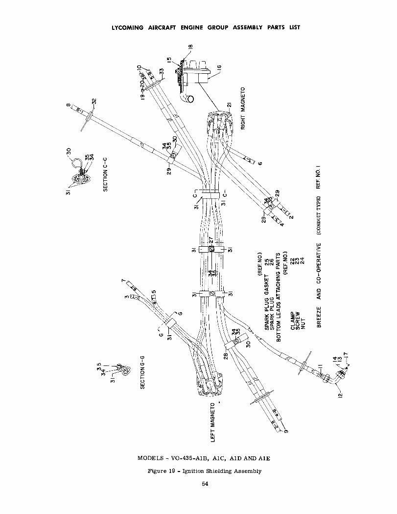
BR
EE
ZE
A
ND
CO
-OP
ER
AT
IVE
(C
ON
DU
IT
TY
PE)
RE
F. N
O. I
7

LYCOMING AIRCRAFT ENGINE GROUP ASSEMBLY PARTS LIST
FIGURE 19 - IGNITION SHIELDING ASSEMBLY
Ref.No.
PartNumber
DescriptionQty.perEng.
ModelUsage1 2 3 4 5
REFERENCE NUMBERS 25,AND 26 ARE NOT ILLUSTRATED.
19-25 STD-295
26 1182-K3
27 52442E-1046-41-8
28 6783E-1348-14-10
29 6778MS21919-G6
30 6802MS21919-G12
31 54219E-1348-13-10
32 5458633 54588
GASKET, Annular, 31/32 OD x 23/32 ID x 5/64 in,(Furnished with spark plug. )
SPARK PLUG, (.018-. 022 gap)(Same as AC SR-87) Alternate to 1182-B3.
BRACKET Co-operativeBRACKET BreezeCLAMP Co-operativeCLAMP BreezeCLAMP Co-operativeCLAMP BreezeCLAMP Co-operativeCLAMP BreezeCLAMP Co-operativeCLAMP BreezeBRACKET (single grommet) Co-operativeBRACKET (dual grommet) Co-operative
ATTACHING PARTS
SCREW Co-operativeSCREW BreezeNUT Co-operativeNUT Breeze
12
12
111133337722
34 6456STD-692
35 5152AN365-1032
7777
FIGURE 20 - IGNITION SHIELDING ASSEMBLY
APPLICABLE MODELS - VO-435-A1F, TVO-435-A1A
20-1 74341 CABLE ASSY., Ignition, shieldedSame as Co-operative Industries, Inc. Chester,N.J. P/N 59686. Does not meet MIL-Specifi-cation AN-I-27. Non-conduit type, spark plugelbows are not procurable.
NOTE
1
74341 shielded ignition cable assy. supersedes69559 and it's alternate 71396 on engine serialnos. beginning with 3064-31 on VO-435-A1Fengines and 237-52 on TVO-435-A1A engines.
Service parts for 74341 are:
2 59651-25043 59651-22044 59651-18045 59651-15046 59651-13047 59651-09048 59687-58049 59688-580410 59687-510411 59687-5604
LEAD ASSY.,LEAD ASSY.,LEAD ASSY.,LEAD ASSY.,LEAD ASSY.,LEAD ASSY.,LEAD ASSY.,LEAD ASSY.,LEAD ASSY.,LEAD ASSY.,
Top No. 1Top No. 2Top No. 3Top No. 4Top No. 5Top No. 6Bottom No. 1Bottom No. 2Bottom No. 3Bottom No. 4
55

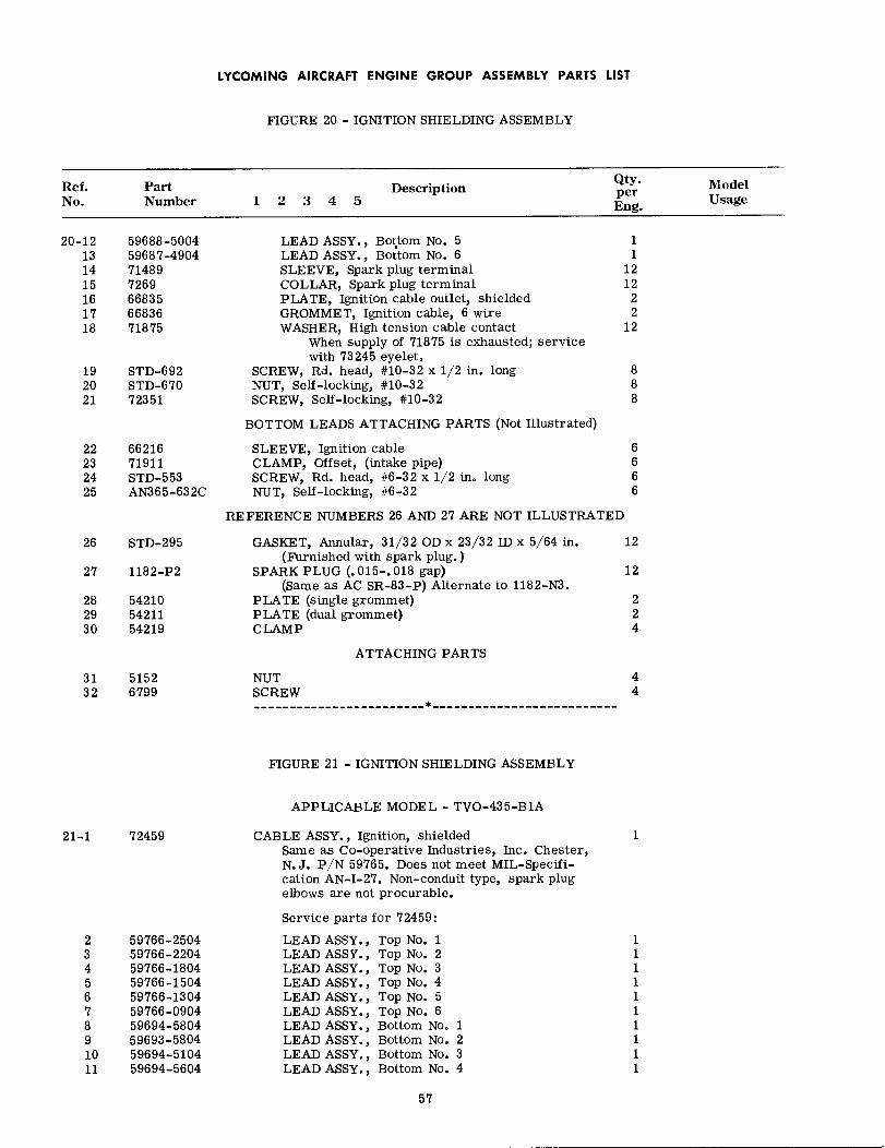
LYCOMING AIRCRAFT ENGINE GROUP ASSEMBLY PARTS LIST
FIGURE 20 - IGNITION SHIELDING ASSEMBLY
Ref.No.
PartNumber
DescriptionQty.perEng.
ModelUsage1 2 3 4 5
20-12 59688-500413 59687-490414 7148915 726916 6683517 6683618 71875
19 STD-69220 STD-67021 72351
LEAD ASSY., Bottom No. 5LEAD ASSY., Bottom No. 6SLEEVE, Spark plug terminalCOLLAR, Spark plug terminalPLATE, Ignition cable outlet, shieldedGROMMET, Ignition cable, 6 wireWASHER, High tension cable contact
When supply of 71875 is exhausted; servicewith 73245 eyelet.
SCREW, Rd. head, #10-32 x 1/2 in. longNUT, Self-locking, #10-32SCREW, Self-locking, #10-32
BOTTOM LEADS ATTACHING PARTS (Not Illustrated)
SLEEVE, Ignition cableCLAMP, Offset, (intake pipe)SCREW, Rd. head, #6-32 x 1/2 in. longNUT, Self-locking, #6-32
11
1212
22
12
888
22 6621623 7191124 STD-55325 AN365-632C
6666
REFERENCE NUMBERS 26 AND 27 ARE NOT ILLUSTRATED
26 STD-295
27 1182-P2
28 5421029 5421130 54219
GASKET, Annular, 31/32 OD x 23/32 ID x 5/64 in.(Furnished with spark plug. )
SPARK PLUG (.015-.018 gap)(Same as AC SR-83-P) Alternate to 1182-N3.
PLATE (single grommet)PLATE (dual grommet)CLAMP
ATTACHING PARTS
NUTSCREW
12
12
224
31 515232 6799
44
FIGURE 21 - IGNITION SHIELDING ASSEMBLY
APPLICABLE MODEL - TVO-435-B1A
21-1 72459 CABLE ASSY., Ignition, shieldedSame as Co-operative Industries, Inc. Chester,N.J. P/N 59765. Does not meet MIL-Specifi-cation AN-I-27. Non-conduit type, spark plugelbows are not procurable.
Service parts for 72459:
1
2 59766-25043 59766-22044 59766-18045 59766-15046 59766-13047 59766-09048 59694-58049 59693-580410 59694-510411 59694-5604
LEAD ASSY.,LEAD ASSY.,LEAD ASSY.,LEAD ASSY.,LEAD ASSY.,LEAD ASSY.,LEAD ASSY.,LEAD ASSY.,LEAD ASSY.,LEAD ASSY.,
Top No. 1Top No. 2Top No. 3Top No. 4Top No. 5Top No. 6Bottom No. 1Bottom No. 2Bottom No. 3Bottom No. 4
57


LYCOMING AIRCRAFT ENGINE GROUP ASSEMBLY PARTS LIST
FIGURE 21 - IGNITION SHIELDING ASSEMBLY
Ref.No.
PartNumber
DescriptionQty.perEng.
ModelUsage1 2 3 4 5
21-121314151617181920
59693-500459694-490472165121879825028668356683671875
LEAD ASSY., Bottom No. 5LEAD ASSY., Bottom No. 6SPRING ASSY.GROMMETSTUDSPRING ASSY.PLATE, Ignition cable outlet, shieldedGROMMET, Ignition cable, 6 wireWASHER, High tension cable contact
When supply of 71875 is exhausted; servicewith 73245 eyelet.
SCREW, Rd. head, #10-32 x 1/2 in. longNUT, Self-locking, #10-32SCREW, Self-locking, #10-32
BOTTOM LEADS ATTACHING PARTS (Not Illustrated)
11
12121212
22
12
888
21 STD-69222 STD-67023 72351
24 6621625 7191126 STD-55327 AN365-632C
SLEEVE, Ignition cableCLAMP, Offset, (intake pipe)SCREW, Rd. head, #6-32 x 1/2 in. longNUT, Self-locking, #6-32
6666
REFERENCE NUMBERS 28 AND 29 ARE NOT ILLUSTRATED
28 STD-295
29 1182-Y3
30 5421031 5421132 54219
GASKET, Annular, 31/32 OD x 23/32 ID x 5/64 in.(Furnished with spark plug.)
SPARK PLUG, 3/4-20 barrel (long reach)(Same as Champion RHB-36P) Alternate to 1182-A4.
PLATE (single grommet)PLATE (dual grommet)CLAMP
12
12
224
ATTACHING PARTS
33 515234 6799
NUTSCREW
44
59
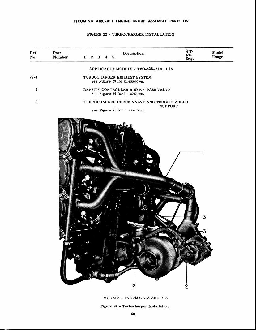
LYCOMING AIRCRAFT ENGINE GROUP ASSEMBLY PARTS LIST
FIGURE 22 - TURBOCHARGER INSTALLATION
Ref. NO.
Part Description Number 12345
Qty. per Eng
22-1
2
3
APPLICABLE MODELS - TVO-435-A1A, B1A
TURBOCHARGER EXHAUST SYSTEM See Figure 23 for breakdown.
DENSITY CONTROLLER AND BY-PASS VALVE See Figure 24 for breakdown.
TURBOCHARGER CHECK VALVE AND TURBOCHARGER SUPPORT
See Figure 25 for breakdown.
MODELS - TVO-435-A1A AND B1A
Figure 22 - Turbocharger Innstallation
60

LYCOMING AIRCRAFT ENGINE GROUP ASSEMBLY PARTS LIST
Ref.No.
PartNumber
FIGURE 23 - TURBOCHARGER EXHAUST SYSTEM
Description1 2 3 4 5
APPLICABLE MODELS - TVO-435-A1A, B1A
MANIFOLD AND PIPING ASSEMBLY
ATTACHING PARTS
Qty.perEng.
ModelUsage
23-1 72906 1
2 STD-353 STD-4754 STD-375 737336 733587 18928 STD-14599 STD-25110 STD-6311 7335712 73356
13 7290314 7290515 7290416 24502-20017 17189-200-N18 72928
WASHER, Plain, 5/16 in.WASHER, Shakeproof lock, 5/16 in.NUT, Plain, 5/16-24STRAP, Clamp exhaust pipeCLAMP, Exhaust manifoldSPRINGBOLT, #10-32 NF-3 x 17/32 in. longWASHER, Internal teeth, #10 lockNUT, #10-32 NF-3CLIP, Exhaust manifoldROD, Exhaust manifold
MANIFOLD ASSEMBLY (right and left)PIPE, Exhaust, leftPIPE ASSY., Exhaust, right
MARMAN COUPLINGMARMAN GASKET (Not Illustrated)
TRANSITION ASSEMBLY, Waste gate
121212
11222611
211111
ATTACHING PARTS
19 AN6C1OA20 AN960C61621 MS20500-624
22 7372023 7336124 73343
BOLT, Hex hd., 3/8-24 x 1-5/64 in. longWASHER, Plain, 3/8 in.NUT, 3/8-24
GASKET, Exhaust manifoldSUPPORT ASSY., TurbochargerBAFFLE, Turbocharger heat, outer
222
1211
61

MA
NIF
OLD
AN
D P
IPIN
G A
SS
EM
BLY
(RE
F. N
O. 1
)

LYCOMING AIRCRAFT ENGINE GROUP ASSEMBLY PARTS LIST
FIGURE 24 - DENSITY CONTROLLER AND BY-PASS VALVE
Ref.No.
PartNumber
DescriptionQty.perEng.
ModelUsage1 2 3 4 5
APPLICABLE MODELS - TVO-435-A1A, B1A
24-1 73784
74423
CONTROLLER, DensitySame as Airesearch Industrial Div., Dwg.#470620, Model CD2-2-1.
CONTROLLER, DensitySame as Airesearch Industrial Div., Model CD2-4.
1 TVO-435-A1A
1 TVO-435-B1A
ATTACHING PARTS
2 STD-375STD-28STD-251
3 733144 AN833-6D5 AN924-6D6 MS29512-67 733218 AN804-D6
AN924-6DMS29512-6
9 73785
74422
10 24502-22524096-225-N
11 16933-225-6
12 73783
SCREW, No. 10-24 NC 3 x 5/8 in. longWASHER, Plain, no. 10WASHER, Internal teeth, no. 10 lock
GASKET, Density controllerELBOW, Flared tube bulkhead, universal 90 °
NUT, Flared tube bulkhead, universal fittingGASKET, Straight thread tube fittingHOSE ASSEMBLY, By-pass valve to controllerTEE, 3/8 in. flared tube with bulkhead on runNUT, Flared tube bulkhead universal fittingGASKET, Straight thread tube fittingVALVE, Exhaust by-pass
Same as Airesearch Industrial Div., Dwg.#470622, Model VB3-2-1.
VALVE, Exhaust by-passSame as Airesearch Industrial Div., Model VB3-4.
COUPLING, J11 Marman Aircraft JointGASKET, Jll Marman Aircraft Joint (Not Illustrated)
(One additional of each shipped loose.)FLANGE, Jll Marman Aircraft Joint (Not Illustrated)
(Shipped loose)HOSE, 3.00 in. ID (Turbocharger to carb. adapter)
444
122211111
1
TVO-435-A1A
TVO-435-B1A
11
1
1
ATTACHING PARTS
13 AN737TW114
14 AN929-6
CLAMP, 3-1/8 to 3-9/16 ID x 9/16 in. wide
CAP ASSY., Press seal 3/8 in. flared tube fitting
2
1
63

LYCOMING AIRCRAFT ENGINE GROUP ASSEMBLY PARTS list
7
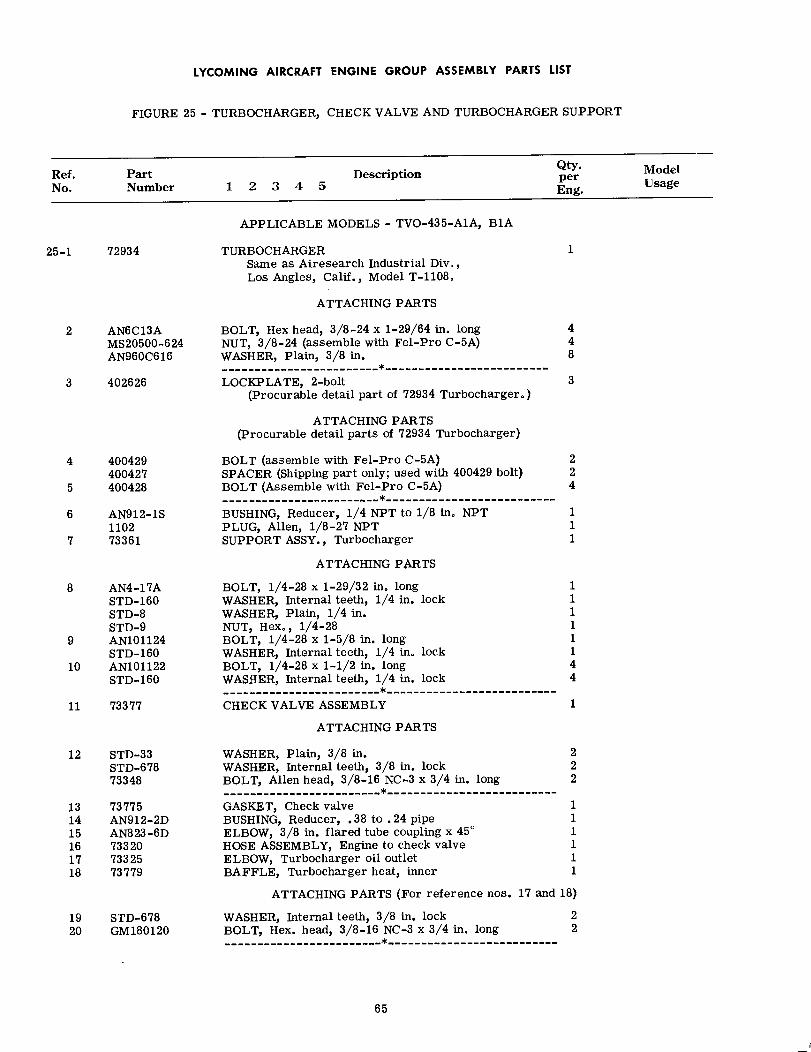
LYCOMING AIRCRAFT ENGINE GROUP ASSEMBLY PARTS LIST
FIGURE 25 - TURBOCHARGER, CHECK VALVE AND TURBOCHARGER SUPPORT
Ref.No.
PartNumber
DescriptionQty.perEng.
ModelUsage1 2 3 4 5
25-1 72934
APPLICABLE MODELS - TVO-435-A1A, B1A
TURBOCHARGERSame as Airesearch Industrial Div.,Los Angles, Calif., Model T-1108.
ATTACHING PARTS
1
2 AN6C13AMS20500-624AN960C616
3 402626
BOLT, Hex head, 3/8-24 x 1-29/64 in. longNUT, 3/8-24 (assemble with Fel-Pro C-5A)WASHER, Plain, 3/8 in.
LOCKPLATE, 2-bolt(Procurable detail part of 72934 Turbocharger.)
ATTACHING PARTS(Procurable detail parts of 72934 Turbocharger)
448
3
4 400429400427
5 400428
6 AN912-1S1102
7 73361
BOLT (assemble with Fel-Pro C-5A)SPACER (Shipping part only; used with 400429 bolt)BOLT (Assemble with Fel-Pro C-5A)
BUSHING, Reducer, 1/4 NPT to 1/8 in. NPTPLUG, Allen, 1/8-27 NPTSUPPORT ASSY., Turbocharger
224
111
8 AN4-17ASTD-160STD-8STD-9
9 AN101124STD-160
10 AN101122STD-160
11 73377
ATTACHING PARTS
BOLT, 1/4-28 x 1-29/32 in. longWASHER, Internal teeth, 1/4 in. lockWASHER, Plain, 1/4 in.NUT, Hex., 1/4-28BOLT, 1/4-28 x 1-5/8 in. longWASHER, Internal teeth, 1/4 in. lockBOLT, 1/4-28 x 1-1/2 in. longWASHER, Internal teeth, 1/4 in. lock
CHECK VALVE ASSEMBLY
11111144
1
ATTACHING PARTS
12 STD-33STD-67873348
13 7377514 AN912-2D15 AN823-6D16 7332017 7332518 73779
WASHER, Plain, 3/8 in.WASHER, Internal teeth, 3/8 in. lockBOLT, Allen head, 3/8-16 NC-3 x 3/4 in. long
GASKET, Check valveBUSHING, Reducer, .38 to .24 pipeELBOW, 3/8 in. flared tube coupling x 45°
HOSE ASSEMBLY, Engine to check valveELBOW, Turbocharger oil outletBAFFLE, Turbocharger heat, inner
222
111111
ATTACHING PARTS (For reference nos. 17 and 18)
19 STD-67820 GM180120
WASHER, Internal teeth, 3/8 in. lockBOLT, Hex. head, 3/8-16 NC-3 x 3/4 in. long
22
65
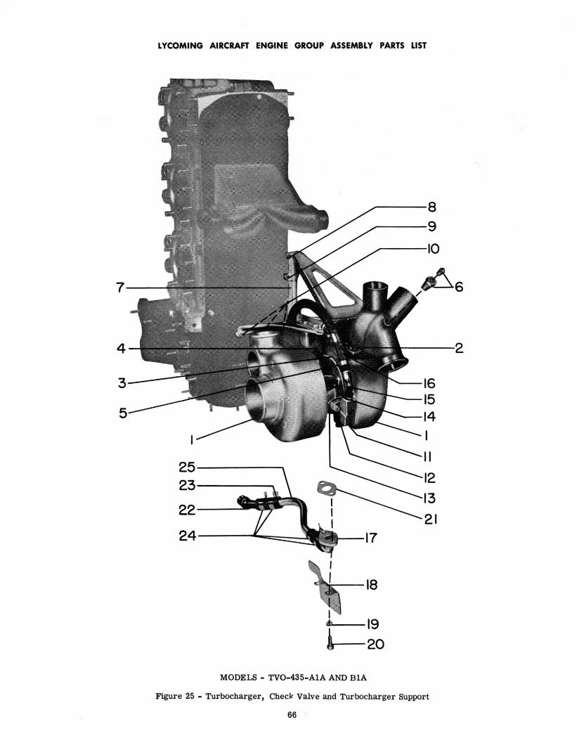
66
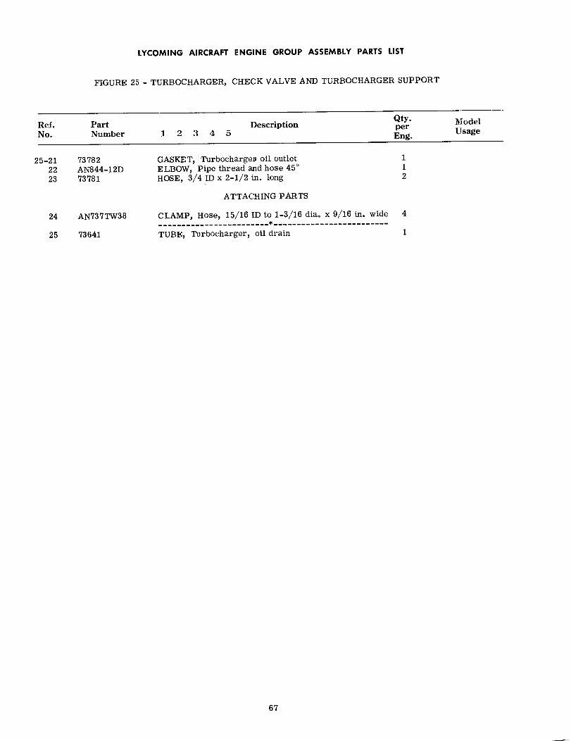
LYCOMING AIRCRAFT ENGINE GROUP ASSEMBLY PARTS LIST
FIGURE 25 - TURBOCHARGER, CHECK VALVE AND TURBOCHARGER SUPPORT
Ref.No.
25-212223
PartNumber
73782AN844-12D73781
DescriptionQty.perEng.
ModelUsage1 2 3 4 5
GASKET, Turbocharger oil outletELBOW, Pipe thread and hose 45 °
HOSE, 3/4 ID x 2-1/2 in. long
ATTACHING PARTS
112
24 AN737TW38
25 73641
CLAMP, Hose, 15/16 ID to 1-3/16 dia. x 9/16 in. wide
TUBE, Turbocharger, oil drain
4
1
67
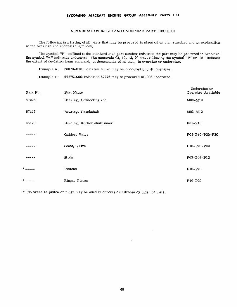
LYCOMING AIRCRAFT ENGINE GROUP ASSEMBLY PARTS LIST
NUMERICAL OVERSIZE AND UNDERSIZE PARTS SECTION
The following is a listing of all parts that may be procured in sizes other than standard and an explanationof the oversize and undersize symbols.
The symbol "P" suffixed to the standard size part number indicates the part may be procured in oversize;the symbol "M" indicates undersize. The numerals 03, 10, 12, 20 etc., following the symbol "P" or "M" indicatethe extent of deviation from standard, in thousandths of an inch, in oversize or undersize.
Example A: 66670-P10 indicates 66670 may be procured in .010 oversize.
Example B: 67276-M03 indicates 67276 may be procured in.003 undersize.
Part No.
67276
67447
66670
* No oversize piston
Part Name
Bearing, Connecting rod
Bearing, Crankshaft
Bushing, Rocker shaft inner
Guides, Valve
Seats, Valve
Studs
Pistons
Rings, Piston
or rings may be used in chrome or nitrided cylinder barrels.
Undersize orOversize Available
M03-M10
M03-M10
P05-P10
P05-P10-P20-P30
P10-P20-P30
P03-P07-P12
P10-P20
P10-P20
68
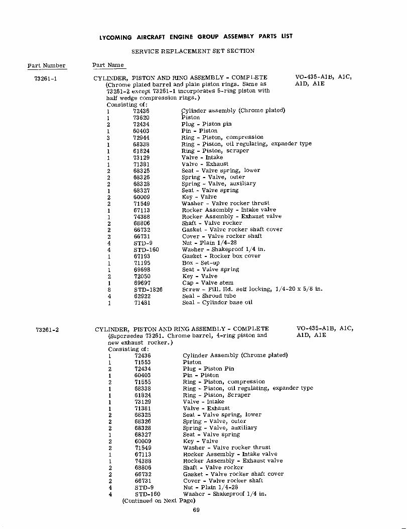
LYCOMING AIRCRAFT ENGINE GROUP ASSEMBLY PARTS LIST
SERVICE REPLACEMENT SET SECTION
Part Number
73261-1
73261-2
Part Name
CYLINDER, PISTON AND RING ASSEMBLY - COMPLETE(Chrome plated barrel and plain piston rings. Same as73261-2 except 73261-1 incorporates 5-ring piston withhalf wedge compression rings.)
VO-435-A1B, A1C,A1D, A1E
Consisting of:1 724361 736202 724341 604033 729441 683381 618241 731291 713812 683252 683262 683281 683272 600092 715491 671131 743882 688062 667322 667314 STD-94 STD-1601 671931 711951 696982 720501 696978 STD-18264 629221 71481
Cylinder assembly (Chrome plated)PistonPlug - Piston pinPin - PistonRing - Piston, compressionRing - Piston, oil regulating, expander typeRing - Piston, scraperValve - IntakeValve - ExhaustSeat - Valve spring, lowerSpring - Valve, outerSpring - Valve, auxiliarySeat - Valve springKey - ValveWasher - Valve rocker thrustRocker Assembly - Intake valveRocker Assembly - Exhaust valveShaft - Valve rockerGasket - Valve rocker shaft coverCover - Valve rocker shaftNut - Plain 1/4-28Washer - Shakeproof 1/4 in.Gasket - Rocker box coverBox - Set-upSeat - Valve springKey - ValveCap - Valve stemScrew - Fill. Hd. self locking, 1/4-20 x 5/8 in.Seal - Shroud tubeSeal - Cylinder base oil
CYLINDER, PISTON AND RING ASSEMBLY - COMPLETE(Supersedes 73261. Chrome barrel, 4-ring piston andnew exhaust rocker.)Cons1121211112221221122244
sisting of:72436 Cylinder Assembly (Chrome plated)71553 Piston72434 Plug - Piston Pin60403 Pin - Piston71555 Ring - Piston, compression68338 Ring - Piston, oil regulating, expan61824 Ring - Piston, Scraper73129 Valve - Intake71381 Valve - Exhaust68325 Seat - Valve spring, lower68326 Spring - Valve, outer68328 Spring - Valve, auxiliary68327 Seat - Valve spring60009 Key - Valve71549 Washer - Valve rocker thrust67113 Rocker Assembly - Intake valve74388 Rocker Assembly - Exhaust valve68806 Shaft - Valve rocker66732 Gasket - Valve rocker shaft cover66731 Cover - Valve rocker shaftSTD-9 Nut - Plain 1/4-28STD-160 Washer - Shakeproof 1/4 in.
(Continued on Next Page)
69
VO-435-A1B, A1C,A1D, A1E
der type

LYCOMING AIRCRAFT ENGINE GROUP ASSEMBLY PARTS LIST
SERVICE REPLACEMENT SET SECTION
Part Number
73261-2
Part Name
CYLINDER, PISTON AND RING ASSEMBLY - COMPLETE (Continued) VO-435-A1B, A1C,Consisting of: A1D, A1E1 67193 Gasket - Rocker box cover1 71195 Box - Set-up1 69698 Seat - Valve spring2 72050 Key - Valve1 69697 Cap - Valve stem8 STD-1826 Screw - Fill. hd. self locking, 1/4-20 x 5/8 in.4 62922 Seal - Shroud tube1 71481 Seal - Cylinder base oil
73804-1 CYLINDER, PISTON AND RING ASSEMBLY - COMPLETE(Nitrided barrels, chrome half wedge compression rings,5-ring piston. )Consisting of:1 73935 Cylinder Assembly (Allison valve1 73932 Piston1 60403 Pin - Piston2 72434 Plug - Piston pin3 73933 Ring - Piston, compression1 73934 Ring - Piston, oil regulating, ex1 69322 Ring - Piston, scraper1 73129 Valve - Intake1 73111 or 73875 Valve - Exhaust (rotator type)1 68325 Seat - Valve spring lower1 73112 Seat - Valve spring, lower2 68326 Spring - Valve, outer2 68328 Spring - Valve, auxiliary1 68327 Seat - Valve spring2 60009 Key - Valve1 73115 Seat - Valve spring (rotator type2 MS13997-3 Key - Valve (rotator type)1 MS13998-3 Cap - Valve stem2 71549 Washer - Valve rocker thrust1 67113 Rocker Assy. - Intake valve1 74388 Rocker Assy. - Exhaust valve2 68806 Shaft - Valve rocker2 66732 Gasket - Valve rocker shaft cove2 66731 Cover - Valve rocker shaft4 STD-9 Nut - Plain, 1/4-284 STD-160 Washer - Shakeproof lock, 1/4 in1 67193 Gasket - Rocker box cover8 STD-1826 Screw - Fill. hd. self locking, 14 62922 Seal - Shroud tube1 71481 Seal - Cylinder base oil1 71195 Box - Set-up
VO-435-A1B,A1C,A1D, A1E, A1F &TVO-435-A1A
e seats)
pander type (narrow)
/4-20 x 5/8 in. long
73804 CYLINDER, PISTON AND RING A(Consisting of:)1 73704 Cyli
1 71553 Pisti1 60403 Pin2 72434 Plug2 71555 Ring1 68338 Ring1 61824 Ring1 73129 Valv1 73111 or 73875 Valv
(Continued on Next Page)
SSEMBLY - COMPLETE
nder Assembly (Chrome plated)(Allison valve seats)
VO-435-A1F &TVO-435-A1A
- on- Piston- Piston pin- Piston, compression- Piston, oil regulating, expander type- Piston scraper
e - Intakee - Exhaust (rotator type)
70

LYCOMING AIRCRAFT ENGINE GROUP ASSEMBLY PARTS LIST
SERVICE REPLACEMENT SET SECTION
Part Number
73804
Part Name
CYLINDER, PISTON AND RING ASSEMBLY - COMPLETE (Continued) VO-435-A1F &Consisting of: TVO-435-A1A1 68325 Seat - Valve spring, lower1 73112 Seat - Valve spring, lower2 68326 Spring - Valve, outer2 68328 Spring, Valve, auxiliary1 68327 Seat - Valve spring2 60009 Key - Valve1 73115 Seat - Valve spring (rotator type)2 MS13997-3 Key - Valve (rotator type)1 MS13998-3 Cap - Valve stem2 71549 Washer - Valve rocker thrust1 67113 Rocker Assy. - Intake valve1 74388 Rocker Assy. - Exhaust valve2 68806 Shaft - Valve rocker2 66732 Gasket - Valve rocker shaft cover2 66731 Cover - Valve rocker shaft4 STD-9 Nut - Plain, 1/4-284 STD-160 Washer - Shakeproof lock, 1/4 in.1 67193 Gasket - Rocker box cover8 STD-1826 Screw - Fill. hd, self-locking, 1/4-20 x 5/8 in. long4 62922 Seal - Shroud tube1 71481 Ring - Oil seal, 3/32 in. dia. section x 4-27/32 in. ID1 71195 Box - Set-up
74035 CYLINDER, PISTON AND RING ASSY. - COMPLETE(Nitrided barrels, chrome half wedge compression rings,5-ring piston. Cylinder assy. incorporates Allison typevalve seats. Requires long reach plugs.
TVO-435-B1A
Consisting of:2 600091 604034 629222 667312 667321 671131 671931 683252 683261 683272 683282 688061 693221 711951 714812 715492 724341 731121 731151 731291 739323 739331 739341 740521 742181 743882 MS13997-31 MS13998-34 STD-94 STD-160
Key - ValvePin - PistonSeal - Shroud tubeCover - Valve rocker shaftGasket - Valve rocker shaft coverRocker Assy. - Intake valveGasket - Rocker box coverSeat - Valve spring, lowerSpring - Valve, outerSeat - Valve springSpring - Valve, auxiliaryShaft - Valve rockerRing - Piston, scraperBox - Set-upSeal - Cylinder base oilWasher - Valve rocker thrustPlug - Piston pinSeat - Valve spring, lowerSeat - Valve spring (rotator type)Valve - IntakePistonRing - Piston compressionRing - Piston, oil reg., expander type (Narrow)Valve - Exhaust, rotator type (inconel)Cylinder Assy. (Nitrided)Rocker Assy. - Exhaust valveKey - Valve (rotator type)Cap - Valve stemNutWasher
71

LYCOMING AIRCRAFT ENGINE GROUP ASSEMBLY PARTS LIST
SERVICE REPLACEMENT SET SECTION
Part Number
69934-1
Part Name
SEAL AND GASKET SETConsisting of:2 STD-111
1 STD-157
1 STD-29412 STD-295
8 720751 STD-5471 STD-17021 STD-17082 AN1239082 AN4047-11 STD-18541 AN900-281 1691-C2 8313
2 456636 60131
24 629221 66224
12 667326 671936 714811 676332 677081 681721 681741 684561 685561 724371 721822 STD-3511 204151 711891 STD-2131 740091 672041 720781 676421 72312
SEAL AND GASKET SET
VO-435-A1B, A1CA1D, A1E
Gasket - Annular (Magneto timingwindow and oil sump)
Gasket - Annular (Oil pressurerelief valve) (Old style)
Gasket - Annular (Thermometer Well Plug)Gasket - Spark plugSeal - Oil (Crankcase halves)Seal - Oil (Tachometer drive gear)Seal - Oil (Starter drive adapter)Seal - Oil (Vacuum pump shaft gear)Ring - Oil seal (Oil pump body assy.)Gasket - Accessory drive (Hand crank and starter pad)Washer - .3125 plainRing - Oil seal (Oil filter assy. )Gasket - Fuel pumpGasket - Vacuum pump (Vacuum pump and tachometer
drive pad)Gasket - MagnetoGasket - Intake flangeSeal - Shroud tubeGasket - CarburetorGasket - Valve rocker shaft coverGasket - Rocker box coverRing - Oil seal (Cylinder base)Gasket - Starter drive padGasket - Starter drive adapterGasket - Crankcase coverGasket - Accessory housingGasket - Hydraulic and oil pump adapterGasket - Accessory housing coverGasket - Oil sumpRing - Oil sealGasket - Annular (oil pressure relief valve)Gasket - Hydraulic pumpBox - Set-upSeal - Oil (Fuel pump)Tube - MailingLockplate - CrankshaftLockplate - Camshaft GearLockwasher - Acc. drive shaftRing - Oil seal
73805-1(This kit does not include gaskets or seals for the overhaulingof the density controller, exhaust by pass valve or turbocharger. )Consisting of:8 72075 Seal - Oil (Crankcase halves)
12 66732 Gasket - Valve rocker shaft cover6 67193 Gasket - Rocker box cover
24 62922 Seal - Shroud tube6 71481 Ring - Oil seal, 3/32 in. dia. sectior6 60131 Gasket - Intake flange1 68172 Gasket - Oil sump1 66224 Gasket - Carburetor1 73189 Gasket - Carburetor inlet1 68174 Gasket - Accessory housing1 73368 Gasket - Scavenge oil inlet adapter2 AN4047-1 Gasket - Accessory drive1 STD-547 Seal - Oil
(Continued on Next Page)
72
VO-435-A1F &TVO-435-A1A
n x 4-27/32 in. ID
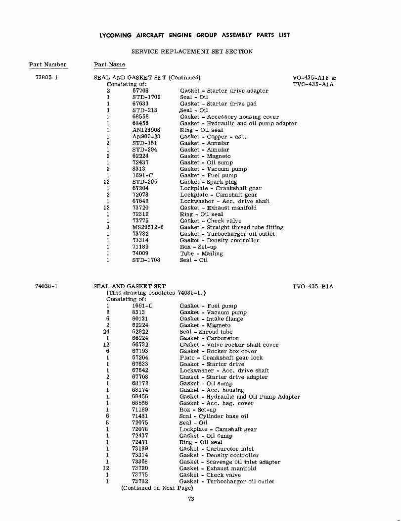
LYCOMING AIRCRAFT ENGINE GROUP ASSEMBLY PARTS LIST
SERVICE REPLACEMENT SET SECTION
Part Number
73805-1
Part Name
SEAL AND GASKET SET (Continued) VO-435-A1F &TVO-435-A1AConsisting of:
2 677081 STD-17021 676331 STD-2131 685561 684561 AN1239081 AN900-282 STD-3511 STD-2942 622241 724372 83131 1691-C
12 STD-2951 672042 720781 67642
12 737201 723121 737753 MS29512-61 737821 733141 711891 740091 STD-1708
Gasket - Starter drive adapterSeal - OilGasket - Starter drive pad,Seal - OilGasket - Accessory housing coverGasket - Hydraulic and oil pump adapterRing - Oil sealGasket - Copper - asb.Gasket - AnnularGasket - AnnularGasket - MagnetoGasket - Oil sumpGasket - Vacuum pumpGasket - Fuel pumpGasket - Spark plugLockplate - Crankshaft gearLockplate - Camshaft gearLockwasher - Acc. drive shaftGasket - Exhaust manifoldRing - Oil sealGasket - Check valveGasket - Straight thread tube fittingGasket - Turbocharger oil outletGasket - Density controllerBox - Set-upTube - MailingSeal - Oil
74038-1 SEAL AN(ThisCons1262
241
12611121111168111111
1211
D GASKET SETs drawing obsoletes 74035-1.)isting of:
TVO-435-B1A
1691-C Gasket - Fuel pump8313 Gasket - Vacuum pump60131 Gasket - Intake flange62224 Gasket - Magneto62922 Seal - Shroud tube66224 Gasket - Carburetor66732 Gasket - Valve rocker shaft cover67193 Gasket - Rocker box cover67204 Plate - Crankshaft gear lock67633 Gasket - Starter drive67642 Lockwasher - Acc. drive shaft67708 Gasket - Starter drive adapter68172 Gasket - Oil sump68174 Gasket - Acc. housing68456 Gasket - Hydraulic and Oil Pump Adapter68556 Gasket - Acc. hsg. cover71189 Box - Set-up71481 Seal - Cylinder base oil72075 Seal - Oil72078 Lockplate - Camshaft gear72437 Gasket - Oil sump72471 Ring - Oil seal73189 Gasket - Carburetor inlet73314 Gasket - Density controller73368 Gasket - Scavenge oil inlet adapter73720 Gasket - Exhaust manifold73775 Gasket - Check valve73782 Gasket - Turbocharger oil outlet
(Continued on Next Page)
73

LYCOMING AIRCRAFT ENGINE GROUP ASSEMBLY PARTS LIST
SERVICE REPLACEMENT SET SECTION
Part Number Part Name
74038-1 SEAL AND GASKET SETConsisting of:1 740091 AN900-282 AN4047-12 AN1239083 MS29512-61 STD-2131 STD-294
12 STD-2952 STD-3511 STD-5471 STD-8291 STD-17021 STD-1708
(Continued)
Tube - MailingGasket - Copper, asbestosGasket - Acc. driveRing - Oil sealGasket - Straight thread tube fittingSeal - OilGasket - AnnularGasket - Spark plugGasket - AnnularSeal - OilGasketSeal - OilSeal - Oil
TVO-435-B1A
(The above kit does not include gaskets or seals for the overhaulingof the density controller, exhaust by pass valve or turbocharger.)
74
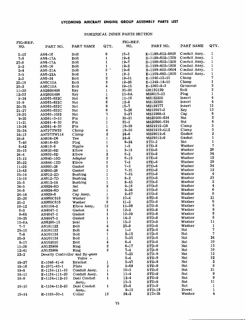
LYCOMING AIRCRAFT ENGINE GROUP ASSEMBLY PARTS LIST
NUMERICAL INDEX PARTS SECTION
FIG-REF.NO.
FIG-REF.NO.PART NO. PART NAME QTY. PART NO. PART NAME QTY.
2-127-9
25-82-22-42-52-3
23-1925-211-3012-33
9-2416-920-2521-2719-359-25
11-2112-2425-2424-1324-8
7-408-42
25-1524-415-1525-2211-3912-4225-1415-1025-624-524-824-1423-2025-219-129-99-65
10-2815-8A
7-725-10
7-825-9
9-1711-3812-4122-2
19-2719-1619-819-1119-9
19-10
19-14
AN4-16 BoltAN4-17A BoltAN4-17A BoltAN6-16 BoltAN6-21A BoltAN6-22A BoltAN6-24 BoltAN6C10A BoltAN6C13A BoltAN280H406 KeyAN280H406 KeyAN365-632C NutAN365-632C NutAN365-632C NutAN365-632C NutAN365-1032 NutAN381-2-10 PinAN381-4-20 PinAN381-4-20 PinAN737TW38 ClampAN737TW114 ClampAN804-D6 TeeAN814-4D PlugAN816-6 NippleAN823-6D ElbowAN833-6D ElbowAN840-10D AdapterAN844-12D ElbowAN900-28 GasketAN900-28 GasketAN912-2D BushingAN912-7D BushingAN912-1S BushingAN924-6D NutAN924-6D NutAN929-6 Cap Assy.AN960C616 WasherAN960C616 WasherAN3104-2 Elbow Assy.AN4047-1 GasketAN4047-1 GasketAN4047-1 GasketAN6290-12 SealAN101122 BoltAN101122 BoltAN101124 BoltAN101124 BoltAN102010 BoltAN123908 RingAN123908 RingDensity Controller and By-pass
6 19-51 19-41 19-71 19-23 19-61 19-32 19-312 19-284 19-151 25-201 15-9A6 11-166 12-86 15-76 5-267 5-271 23-211 25-21 19-294 19-302 24-61 24-81 9-241 1-51 2-132 6-22 6-151 7-21 7-21 7-211 7-351 8-21 8-452 9-181 9-361 9-672 10-48 11-2
12 11-361 12-21 12-391 14-21 15-34 25-84 1-31 2-151 5-354 6-42 6-172 7-4
7-238-4
1 8-472 9-691 10-21 11-41 12-4
15-51 25-8
9-1512 24-2
E-1199-602-0908E-1199-602-1200E-1199-602-1200E-1199-602-1808E-1199-603-0604E-1199-603-1800E-1348-13-10E-1348-14-10E-1360-9-3GM180120MS9015-12MS122200MS122200MS124777MS13997-3MS13998-3MS20500-624MS20500-624MS21919-G6MS21919-G12MS29512-6MS29512-6STD-2STD-8STD-8STD-8STD-8STD-8STD-8STD-8STD-8STD-8STD-8STD-8STD-8STD-8STD-8STD-8STD-8STD-8STD-8STD-8STD-8STD-8STD-9STD-9STD-9STD-9STD-9STD-9STD-9STD-9STD-9STD-9STD-9STD-9STD-9STD-9STD-9STD-19STD-28
Conduit Assy.Conduit Assy.Conduit Assy.Conduit Assy.Conduit Assy.Conduit Assy.ClampClampGrommetBoltPlugInsertInsertInsertKeyCapNutNutClampClampGasketGasketNutWasherWasherWasherWasherWasherWasherWasherWasherWasherWasherWasherWasherWasherWasherWasherWasherWasherWasherWasherWasherWasherNutNutNutNutNutNutNutNutNutNutNutNutNutNutNutDowelWasher
11111171221441312624332117263412293412433
246821
96968
11177
241012101232
28
2199
11114
E-1046-41-8E-1071-42-1E-1134-111-10E-1134-111-20E-1134-112-10
E-1134-112-20
E-1181-30-1
Valve -BracketPlateConduit Assy.Conduit Assy.Dual Conduit
Assy.Dual Conduit
Assy.Collar
75
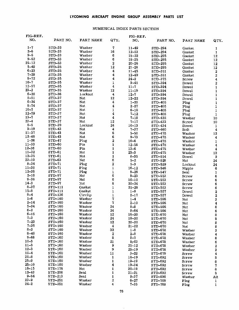
LYCOMING AIRCRAFT ENGINE GROUP ASSEMBLY PARTS LIST
NUMERICAL INDEX PARTS SECTION
FIG-RE F. FIG-RE F.NO. PART NO. PART NAME QTY. NO. PART NO. PART NAME QTY.
1-7 STD-33 Washer 7 11-49 STD-294 Gasket 12-6 STD-33 Washer 16 12-53 STD-294 Gasket 19-6 STD-33 Washer 6 18-22 STD-295 Gasket 129-62 STD-33 Washer 6 19-25 STD-295 Gasket 12
25-12 STD-33 Washer 2 20-26 STD-295 Gasket 125-49 STD-35 Washer 12 21-28 STD-295 Gasket 126-23 STD-35 Washer 4 11-45 STD-351 Gasket 27-29 STD-35 Washer 4 12-49 STD-351 Gasket 29-72 STD-35 Washer 4 24-2 STD-375 Screw 4
10-7 STD-35 Washer 1 9-41 STD-394 Dowel 212-57 STD-35 Washer 4 11-7 STD-394 Dowel 123-2 STD-35 Washer 12 11-19 STD-394 Dowel 1
6-25 STD-36 Locknut 4 12-7 STD-394 Dowel 15-51 STD-37 Nut 12 12-22 STD-394 Dowel 16-24 STD-37 Nut 4 1-25 STD-405 Plug 19-74 STD-37 Nut 4 2-27 STD-405 Plug 1
10-5 STD-37 Nut 1 6-10 STD-405 Plug 112-59 STD-37 Nut 4 7-12 STD-405 Plug 113-7 STD-37 Nut 4 7-18 STD-425 Washer 1023-4 STD-37 Nut 12 7-17 STD-433 Screw 10
5-5 STD-39 Locknut 24 10-13 STD-434 Dowel 19-19 STD-43 Nut 4 7-37 STD-460 Bolt 4
11-37 STD-43 Nut 6 5-50 STD-475 Washer 1212-40 STD-43 Nut 6 9-73 STD-475 Washer 4
1-26 STD-47 Plug 2 10-6 STD-475 Washer 111-33 STD-60 Pin 1 12-58 STD-475 Washer 412-36 STD-60 Pin 1 13-6 STD-475 Washer 411-32 STD-61 Nut 1 23-3 STD-475 Washer 1212-35 STD-61 Nut 1 8-35 STD-514 Dowel 223-10 STD-63 Nut 6 5-2 STD-528 Nut 248-34 STD-71 Plug 2 5-3 STD-529 Locknut 24
11-35 STD-71 Plug 1 16-12 STD-546 Nipple 612-38 STD-71 Plug 1 9-26 STD-547 Seal 1
2-16 STD-97 Nut 6 9-23 STD-553 Screw 69-38 STD-97 Nut 6 16-10 STD-553 Screw 6
14-3 STD-97 Nut 8 20-24 STD-553 Screw 68-37 STD-111 Gasket 1 21-26 STD-553 Screw 6
15-8 STD-111 Gasket 1 1-9 STD-557 Dowel 29-4 STD-136 Circlip 1 2-17 STD-557 Dowel 21-6 STD-160 Washer 7 1-4 STD-596 Nut 32-14 STD-160 Washer 7 2-10 STD-596 Nut 45-34 STD-160 Washer 24 9-8 STD-596 Nut 66-3 STD-160 Washer 24 9-64 STD-596 Nut 66-16 STD-160 Washer 12 18-20 STD-670 Nut 87-3 STD-160 Washer 24 19-20 STD-670 Nut 87-22 STD-160 Washer 12 20-20 STD-670 Nut 87-36 STD-160 Washer 4 21-22 STD-670 Nut 88-3 STD-160 Washer 32 1-8 STD-678 Washer 38-46 STD-160 Washer 2 2-9 STD-678 Washer 49-68 STD-160 Washer 8 9-7 STD-678 Washer 6
10-3 STD-160 Washer 21 9-63 STD-678 Washer 611-3 STD-160 Washer 9 25-12 STD-678 Washer 212-3 STD-160 Washer 9 25-19 STD-678 Washer 215-4 STD-160 Washer 11 3-22 STD-679 Screw 425-8 STD-160 Washer 1 18-19 STD-692 Screw 825-9 STD-160 Washer 1 19-19 STD-692 Screw 825-10 STD-160 Washer 4 19-34 STD-692 Screw 716-15 STD-176 Nut 1 20-19 STD-692 Screw 812-43 STD-208 Seal 1 21-21 STD-692 Screw 8
9-54 STD-213 Seal 1 9-37 STD-696 Washer AR23-9 STD-251 Washer 2 6-27 STD-709 Plug 124-2 STD-251 Washer 4 7-33 STD-709 Plug 1
76

LYCOMING AIRCRAFT ENGINE GROUP ASSEMBLY PARTS LIST
NUMERICAL INDEX PARTS SECTION
FIG-RE F. FIG-REF.NO. PART NO. PART NAME QTY. NO. PART NO. PART NAME QTY.
2-8 STD-713 Pin 1 16-14 STD-1900 Nipple 12-26 STD-740 Plug 1 6-12 STD-1901 Stud 4
10-12 STD-740 Plug 1 7-14 STD-1901 Stud 411-34 STD-740 Plug 1 22-1 Turbocharger Exhaust System -12-37 STD-740 Plug 1' 22-3 Turbocharger Check Valve and
2-36 STD-783 Plug 2 Turbocharger Support -5-17 STD-783 Plug 6 13-13 10-4092 Nut 1
10-19 STD-783 Plug 1 13-12 10-4093 Washer 17-39 STD-829 Gasket 1 13-12A 10-4093 Washer 2
16-11 STD-853 Tee 5 13-14 10-90751-19 Pin 13-10 STD-858 Key 1 13-14A 10-90751-19 Pin 25-14 STD-859 Dowel 12 13-13A 10-163151 Nut 28-9 STD-859 Dowel 1 1-22 25-8 Stud 4
16-16 STD-869 Cone 1 5-15 25-8 Stud 241-2 STD-872 Nut 4 2-37 25-10 Stud 12-7 STD-872 Nut 4 8-41 25-10 Stud 2
10-9 STD-951 Dowel 1 1-29 25-11 Stud 2210-11 STD-951 Dowel 1 2-34 25-11 Stud 4
3-19 STD-1066 Dowel 1 8-13 25D-11 Stud 810-22 STD-1104 Plug 2 1-31 25-12 Stud 412-14 STD-1164 Insert 1 5-12 25-12 Stud 12
7-11 STD-1164 Insert 4 8-14 25-12 Stud 108-10 STD-1173 Insert 4 8-15 25-12 Stud 12-11 STD-1230 Bolt 7 10-16 25-12 Stud 56-6 STD-1230 Bolt 10 1-14 25-13 Stud 77-6 STD-1230 Bolt 9 8-16 25-13 Stud 157-6 STD-1230 Bolt 10 8-17 25-13 Stud 28-5 STD-1230 Bolt 1 8-19 25-16 Stud 4
15-14 STD-1252 Clamp 12 10-14 25D-16 Stud 66-21 STD-1269 Clamp 12 10-15 25-17 Stud 17-27 STD-1269 Clamp 12 11-8 25D-21 Stud 21-18 STD-1315 Insert 3 12-9 25D-21 Stud 22-23 STD-1315 Insert 17 8-17 25-23 Stud 28-10 STD-1315 Insert 4 8-18 25-23 Stud 18-6 STD-1339 Plug 5 8-20 25D-24 Stud 1
11-12 STD-1392 Plug 1 11-9 25D-24 Stud 212-16 STD-1392 Plug 1 12-10 25D-24 Stud 223-8 STD-1459 Bolt 2 11-10 25D-25 Stud 215-16 STD-1576 Hose 2 12-11 25D-25 Stud 2
2-38 STD-1623 Insert 1 8-21 25-27 Stud 115-19 STD-1640 Clamp 4 8-15 25-28 Stud 1
6-5 STD-1679 Bolt 10 10-15 25-29 Stud 16-5 STD-1679 Bolt 14 8-22 25-34 Stud 27-5 STD-1679 Bolt 9 8-23 25-37 Stud 17-5 STD-1679 Bolt 14 8-24 25-40 Stud 15-54 STD-1686 Screw 4 5-11 31-12 Stud 125-53 STD-1687 Washer 4 12-12 31-12 Stud 16-7 STD-1688 Bolt 4 15-6 31-12 Stud 6
14-6 STD-1698 Ring 1 8-25 31-14 Stud 69-42 STD-1702 Seal 1 10-17 31-14 Stud 19-52 STD-1708 Seal 1 12-13 31-14 Stud 39-44 STD-1709 Circlip 1 15-6 31-14 Stud 6
13-5 STD-1727 Washer 4 1-23 31-15 Stud 36-20 STD-1792 Hose 6 2-29 31-15 Stud 17-26 STD-1792 Hose 6 6-9 31-15 Stud 4
15-13 STD-1793 Hose 6 2-25 31-21 Stud 25-40 STD-1826 Screw 48 8-26 31-21 Stud 19-31 STD-1833 Screw 6 2-30 31-24 Stud 18-32 STD-1847 Plug 1 8-27 31-26 Stud 14-11 STD-1853 Pin 12 1-24 38-12 Stud 29-22 STD-1854 Washer 1 1-13 38-13 Stud 249-23 STD-1860 Screw 1 2-21 38-13 Stud 24
77

LYCOMING AIRCRAFT ENGINE GROUP ASSEMBLY PARTS LIST
NUMERICAL INDEX PARTS SECTION
FIG-RE F.NO. PART NO. PART NAME QTY.
FIG-RE F.NO. PART NO. PART NAME QTY.
8-281-191-201-172-28
10-181-122-205-4
11-4612-509-619-61
10-2711-1412-18
1-162-337-388-339-47
10-2116-1725-618-2319-2620-2721-2911-5012-549-75
23-721-1718-2719-3520-3121-3319-1719-1219-1419-3419-2919-2818-2820-3221-3419-3021-1420-1521-16
9-7010-2624-1123-1712-6024-1023-1624-1014-5
3-221-15
38-1638-1938-2138D-1938D-1938-3150-1550-15383-B662662671-B671-B671-B1028-B1028-B110211021102110211021102110211021182-K31182-K31182-P21182-Y3154015401691-C18925028515251525152515254225585565164566778678367996799679968027216726979828313831316933-225-617189-200-N2041524096-225-N24502-20024502-225303114522651218
Stud 6Stud 2Stud 2Stud 4Stud 1Stud 6Stud 12Stud 12Nut 24Nut 1Nut 1Cover 1Cover 2Cover 1Ball 1Ball 1Plug 4Plug 4Plug 1Plug 1Plug 1Plug 2Plug 6Plug 1Spark Plug 12Spark Plug 12Spark Plug 12Spark Plug 12Plug 1Plug 1Gasket 1Spring 2Spring Assy. 12Nut 4Nut 7Nut 4Nut 4Nail 12Elbow Assy. 12Collar 12Screw 7Clamp 3Clamp 1Screw 4Screw 4Screw 4Clamp 3Spring Assy. 12Collar 12Stud 12Gasket 2Gasket 1Flange 1Marman Gasket 1Gasket 1Gasket 1Marman Coupling 1Coupling 1Bearing 1Tube 6Grommet 12
19-1619-2718-2420-2821-3018-2520-2921-3118-2619-3120-3021-3219-3219-3318-718-618-518-418-318-218-1318-1218-1018-1118-818-919-819-519-10
19-319-719-219-619-9
19-419-1120-720-620-520-420-320-220-1320-1020-1120-820-1220-921-1221-921-1321-1021-1121-821-721-621-521-421-3
524265244254210542105421054211542115421154219542195421954219545865458858513-090458513-130458513-150458513-180458513-220458513-250458513-490458513-500458513-510458513-560458513-580458513-5804592735927459275
5927659277592785927959280
592815928259651-090459651-130459651-150459651-180459651-220459651-250459687-490459687-510459687-560459687-580459688-500459688-580459693-500459693-580459694-490459694-510459694-560459694-580459766-090459766-130459766-150459766-180459766-2204
PlateBracketPlatePlatePlatePlatePlatePlateClampClampClampClampBracketBracketLead Assy.Lead Assy.Lead Assy.Lead Assy.Lead Assy.Lead Assy.Lead Assy.Lead Assy.Lead Assy.Lead Assy.Lead Assy.Lead Assy.Conduit Assy.Conduit Assy.Dual Conduit
Assy.Conduit Assy.Conduit Assy.Conduit Assy.Conduit Assy.Dual Conduit
Assy.Conduit Assy.Conduit Assy.Lead Assy.Lead Assy.Lead Assy.Lead Assy.Lead Assy.Lead Assy.Lead Assy.Lead Assy.Lead Assy.Lead Assy.Lead Assy.Lead Assy.Lead Assy.Lead Assy.Lead Assy.Lead Assy.Lead Assy.Lead Assy.Lead Assy.Lead Assy.Lead Assy.Lead Assy.Lead Assy.
21222222474422111111111111111
11111
1111111111111111111111111
78

LYCOMING AIRCRAFT ENGINE GROUP ASSEMBLY PARTS LIST
NUMERICAL INDEX PARTS SECTION
FIG-RE F.NO.
FIG-REF.NO.PART NO. PART NAME QTY. PART NO. PART NAME QTY.
21-24-95-265-266-147-206-187-244-59-66
10-259-27
11-2612-29
5-446-117-13
13-1516-416-616-516-216-116-34-44-4A
13-816-8
5-451-212-243-175-524-83-218-12
20-2221-246-267-32
11-2412-27
5-135-85-215-425-65-435-335-321-102-185-10
18-1620-1621-1818-1719-1520-1721-19
1-11
59766-2504600076000960009600696006960131601316040360430604306043161297612976150361548615486156661581-161581-361581-461581-561581-961581-106182461824622246225462922650076500765074656146581966144661456621666216662246622466426664266667066713667146671766720667286673166732667346673466796 P106683566835668356683666836668366683666990
Lead Assy.BoltKeyKeyFlangeFlangeGasketGasketPinCoverCoverCoverImpellerImpellerSleevePlatePlateKit Assy.Tube Assy.Tube Assy.Tube Assy.Tube Assy.Tube Assy.Tube Assy.RingRingGasketClipSealRetainerRetainerSocketPlugBushingLockplateDowelSleeveSleeveGasketGasketImpellerImpellerBushingGuideValveSpringSeatWasherCoverGasketStudStudInsertPlatePlatePlateGrommetGrommetGrommetGrommetStud
1 2-1912 5-3612 5-2924 5-30
6' 5-386 5-486 3-126 4-76 4-122 3-141 1-301 9-281 9-391 9-43
12 9-291 9-271 9-452 14-41 14-12 14-91 14-82 8-382 10-82 3-116 3-136 9-12 9-516 9-32
24 9-3312 8-712 11-2912 12-324 9-536 5-72 11-482 12-526 11-436 12-471 11-201 12-231 6-131 7-15
24 8-436 9-466 5-226 5-226 5-23
AR 5-2512 5-2512 5-244 4-34 4-3A
12 11-252 12-282 11-272 12-302 9-212 10-12 11-512 12-556 11-18
66990671126711367114671936719567204672756727667447674536758367596676056760967610676336763867639676416764267646676536768767688676906770467708677096774267762677626778267835679406794067981679816816168161681726817268174681866832568325683266832768327683286833868338684036840368404684046841068440684566845668466
StudRocker Assy.Rocker Assy.BushingGasketFlangePlateRod Assy.BearingBearingDowelGearBushingJawGearGear Assy.GasketShimAdapterNutLockwasherBushingBushingGearNutWasherShaft Gear Assy.GasketShimBushingDowelDowelShaft Gear Assy.SeatNutNutPlungerPlungerShaftShaftGasketGasketGasketAdapterSeatSeatSpringSeatSeatSpringRingRingImpellerImpellerImpellerImpellerGear Assy.Cover Assy.GasketGasketBushing
66666616
12881111111111111111211111611111111116
1212
61212
66111111111
79

LYCOMING AIRCRAFT ENGINE GROUP ASSEMBLY PARTS LIST
NUMERICAL INDEX PARTS SECTION
FIG-RE F.NO.
11-612-612-2111-3112-3411-2212-2511-1112-1511-4412-489-129-209-16
10-249-149-489-13
10-109-351-152-223-145-31
14-79-60
13-119-59
13-106-16-196-196-197-257-257-253-99-2
13-913-9A
5-108-114-4A8-31
15-95-99-113-159-569-589-559-579-59-499-501-272-316-87-10
11-2311-17
PART NO. PART NAME
68466 Bushing68466 Bushing68466 Bushing68467 Gear68467 Gear68468 Spacer68468 Spacer68473 Sleeve68473 Sleeve68542 Spring68542 Spring68544 Shaft68545 Washer Assy.68553 Gear68556 Gasket68563 Bushing68565 Gear68568 Hub Assy.68590 Bushing68694 Adapter Assy.68751 Stud68751 Stud68763 Bearing68806 Shaft68835 Gear68874 Cushion68874 Cushion68875 Retainer68875 Retainer68951 Cover Assy.68955 Pipe68956 Pipe68957 Pipe68955 Pipe68956 Pipe68957 Pipe68965 Bolt69177 Gear Assy.69208 Coupling69208 Coupling69260 P10 Insert69286 Annulus69322 Ring69335 Plug69335 Plug69358 Guide69494 Chain Assy.69529 Body69565 Sleeve69565 Sleeve69566 Shaft Assy.69567 Coupling Assy.69568 Cover Assy.69569 Washer69570 Ring69580 Dowel69580 Dowel69602 Connection69602 Connection69605 Shaft69618 Body Assy.
QTY.
11111111111111111111448
121442212222228112
12161161
121111111226611
FIG-RE F.NO.
12-205-395-391-16-228-36
8-293-13-83-79-3
11-2812-318-308-13-20
15-1115-1212-26
2-225-95-275-252-359-105-163-31-282-323-63-1A
11-511-112-112-517-1
8-88-1A
15-12-395-12-18-1B8-1C
19-13-23-1B3-5
11-4012-4413-15A
8-4010-20
5-475-475-476-22
15-213-415-11
PART NO. PART NAME QTY.
696186962569626696286963369636
696376964069641696426964569647696476965869661696626966369664696716967969693696976969869796698106981469815698236982369844698516989269893699376993869947702927029370319703387035370403704047040670423704327043370434704607046070497711237112471135711367113771139711427116371203
Body Assy. 1Cover Assy. 3Cover Assy. 3Crankcase Assy. 1Carburetor 1Tube and Strainer 1
Assy.Plug 1Crankshaft Assy. 1Dowel 3Bushing 1Jaw 1Dowel 1Dowel 1Pin 1Hsg.Assy.Acc. 1Gear 1Tube 1Tube 1Shaft 1Stud 4Guide 6Cap 6Seat 6Dowel 8Cap Assy. 1Dowel 6Plug 1Stud 8Stud 8Tube 1Crankshaft Assy. 1Body Assy. 1Pump Assy. 1Pump Assy. 1Body Assy. 1Baffle Assy. 4Plug 1Hsg.Assy.Acc. 1Sump Assy. 1Spacer 2Cylinder Assy. 6Crankcase Assy. 1Hsg. Assy. Acc. 1Hsg. Assy. Acc. 1Cable Assy. 1Plug 1Crankshaft Assy. 1Jet 1Washer 1Washer 1Kit Assy. 2Bushing 1Bushing 1Rod Assy. ARRod Assy. ARRod Assy. ARCarburetor 1Sump Assy. 1Magneto 1Tube 1
80

LYCOMING AIRCRAFT ENGINE GROUP ASSEMBLY PARTS LIST
NUMERICAL INDEX PARTS SECTION
FIG-RE F.NO.
15-1211-4112-4511-4712-51
3-188-395-21
18-118-1513-213-113-113-2
5-4618-1419-1320-14
6-225-285-285-285-284-14-2
13-1713-1617-3
9-4017-2
6-227-286-22
15-1115-1211-1A11-512-512-1A11-4212-46
3-1616-13
5-1A18-1819-1820-1821-20
5-75-6
16-79-22
20-2321-25
4-1011-1312-1713-315-18
5-261-322-41
PART NO. PART NAME
71204 Tube71224 Oil filter assy.71224 Oil filter assy.71226 Screw71226 Screw71304 Camshaft Assy.71341 Bushing71381 Valve71396 Cable Assy.71401 Collar71435 Magneto71436 Magneto71437 Magneto71438 Magneto71481 Ring71489 Sleeve71489 Sleeve71489 Sleeve71546 Carburetor71549 Washer71549-1 Washer71549-2 Washer71549-3 Washer71553 Piston71555 Ring71571 Kit71574 Kit71611 Retainer71616 Bushing71629 Hook71684 Carburetor71684 Carburetor71685 Carburetor71702 Tube71702 Tube71769 Pump Assy.71770 Body Assy.71771 Body Assy.71772 Pump Assy.71774 Cover71774 Cover71791 Plunger Assy.71811 Sleeve71850 Cylinder Assy.71875 Washer71875 Washer71875 Washer71875 Washer71894 Seat71895 Seat71910 Clamp71911 Clamp71911 Clamp71911 Clamp71950 Nut71999 Retainer71999 Retainer72038 Magneto72045 Hose72050 Key72075 Seal72075 Seal
QTY.
111
61
1211116
121212
1ARARARAR
612
1241411111111111
1266
12121212666666
121111
1288
FIG-RE F.NO.
3-219-309-343-33-73-45-185-19
18-2119-2120-2121-23
9-1212-566-214-65-1B
15-2021-13-1C3-33-4
11-4112-45
5-41
3-163-155-9
23-1323-1523-1423-1
23-1825-1
7-28A4-2A3-15
11-512-512-1B11-1B10-1A
5-215-225-255-207-41
24-325-1624-725-17
7-1923-24
6-147-207-34
25-1223-1223-1123-6
PART NO. PART NAME QTY.
72078721397218272305723087231272343723447235172351723517235172384724127241772434724367243772459724697247072471727857278572839
72876728777289772903729047290572906
72928729347293672944730617308673088730897309173094731117311273115731297318973314733207332173325733427334373346733467334773348733567335773358
Lockplate 2Dowel 3Ring 1Plug 1Bushing 1Ring 1Stabilizer 6Stabilizer 6Screw 8Screw 8Screw 8Screw 8Shaft 1Cover 1Clamp 12Plug 12Cylinder Assy. 6Gasket 1Cable Assy1 1Crankshaft Assy. 1Plug 1Ring 1Oil filter assy. 1Oil filter assy. 1Shroud Tube 12
Assy.Plunger Assy. 12Body 12Guide 6Manifold Assy. 2Pipe Assy. 1Pipe 1Manifold and 1
Piping Assy.Transition Assy. 1Turbocharger 1Carburetor 1Ring 18Body 12Body Assy. 1Body Assy. 1Pump Assy. 1Pump Assy. 1Cover Assy. 1Valve 6Seat 6Seat 6Valve 6Gasket 1Gasket 1Hose Assy. 1Hose Assy. 1Elbow 1Breather Assy. 1Baffle 1Flange 6Flange 6Adapter 1Bolt 2Rod 1Clip 1Clamp 1
81
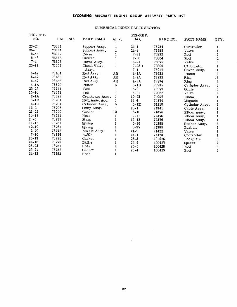
LYCOMING AIRCRAFT ENGINE GROUP ASSEMBLY PARTS LIST
NUMERICAL INDEX PARTS SECTION
FIG-REF.NO.
FIG-RE F.NO.PART NO. PART NAME QTY. PART NO. PART NAME QTY.
23-2325-7
8-448-487-1
25-11
5-475-475-474-1A
25-2515-10
2-1A8-1D5-1C
15-223-2215-1723-511-1512-192-407-16
25-1325-1825-2325-2124-12
733617336173367733687337573377
73434734357343673620736417367173697737017370473705737207373173733737617376173772737747377573779737817378273783
Support Assy.Support Assy.CoverGasketCover Assy.Check Valve
Assy.Rod Assy.Rod Assy.Rod Assy.PistonTubeTeeCrankcase Assy.Hsg. Assy, Acc.Cylinder Assy.Sump Assy.GasketHoseStrapSpringSpringNozzle Assy.BaffleGasketBaffleHoseGasketHose
1 24-11 24-91 7-311 7-301 5-211 7-28B
7-1AR 4-1AAR 4-2AAR 4-3A
6 5-1D1 5-91 5-211 10-231 13-46 5-1E1 20-1
12 6-101 7-121 16-181 5-361 5-376 24-91 24-11 25-31 25-42 25-51 25-41
737847378573833738647387573899739177393273933739347393573979740527409774174742187434174376743767437674388743897442274423402626400427400428400429
ControllerValveBoltBoltValveCarburetorCover Assy.PistonRingRingCylinder Assy.GuideValveElbowMagnetoCylinder Assy.Cable Assy.Elbow Assy.Elbow Assy,Elbow Assy.Rocker Assy.BushingValveControllerLockplateSpacerBoltBolt
11226116
186666116111166113242
82