lyft mobile - docs.i3-technologies.com
TRANSCRIPT

LYFT MOBILE(max. 86 inch / 120 kg)
1. BASIC KIT
- 1 -
Edited by : S. VrankenChecked by : N. VoldersApproved by : G. Van Erum
1.7 hardware (BS/A210010)
- 6*16 (1.7.1) eachscrew M 16
- ( .2) 4 eachU-spacer 1.7
- screw M8*30 (1.7.3) 2 each
1.3
1.2
1.2
1.1
Adapterkit VESA 600 high(see pg.7)
Instr.mount.-LYFT-01-11-2020
1.8
1.7
A.2 A.1 A.1
- set screw M8*30 (1.7.4) 2 each
- nut M8 (1.7.5) 2 each
1.5
1. .1 pre-assembled4 on VESA-mount (1.3)1. .2 loose4
1.6.2 used if optionONLYfront control1.6.2
1 6.. 1 pre-assembled on VESA-mount (1.3)

- 2 -
Edited by : S. VrankenChecked by : N. VoldersApproved by : G. Van Erum Instr.mount.-LYFT-01-11-2020
IMPORTANT SAFETY INFORMATION
Thoroughly read the safety instructions below before starting the installation. Failure of reading, understanding and
following all instructions can result in serious personal injury, equipment damage, or voiding factory warranty. This
product has been tested and certified on multiple strict safety standards, but which do not cover inproper handling
and/or installation of the device.
Make sure that all installers, users, and operators of the height adjustable trolley are thorougly informed about the
safety instructions and warnings. Do not throw away this manual, but keep it for further reference to instruct future
users and operators about the important safety instructions.
INSTALLATION WARNINGS
The assembly and installation should only be executed by qualified technicians.
ELECTRICAL SAFETY
1. Only connect this device to a grounded power outlet of the specified rating: 230V-AC 50Hz.
2. Apply safety measurements to the power cable, to prevent damage to the electrical components.
3. When noticing physical damage to the power cable, unplug the device immediately and replace the powercable.
4. Before relocating the product, always disconnect the device from the power outlet.
5. Do not place the product near any water sources that might spill onto the device.
MECHANICAL SAFETY
6. Do not assembly the device with any other custom parts than provided by the manufacturer.
7. Do not deviate from the instructions illustrated in this manual.
8. Do not exceed the load capacity of this product. Respect the maximum load specification of 120kg. Overloading
8. may result in the unit tipping over and can result in equipment damage and/or serious injury or even death.
9. Do not use this unit for any other purpose than its intended use, as described in this document.
10. Do not attach other custom parts to it.
OPERATION WARNINGS
Make sure that all users/operators are properly informed about these warnings.
11. Do not use this unit for other purposes than its intended use, as described in this document.
12. Don't attach custom parts to it.
13. Do not position the trolley on sloped or oneven surfaces or near balconies, ledges, stairs,platforms, steps, etc...
14. Lock the wheel brakes while in operation, after relocating the unit.
15. Always move the trolley with the display in lowest position.
16. When raising and lowering the height adjustible lift, always make sure that there are no obstructions or collisions.
17. Do not place object beneath the unit.
EU DECLARATION OF CONFORMITY
i3-Technologies N.V. declares that this product is in compliance with the essential requirements and
other relevant provisions of Directives 2014/30/EU, 2014/35/EU, and 2011/65/EU, where applicable.
The availability of products may vary by region. For more info, contact your dealer.This device may
contain commodities, technology or software subject to export laws and regulations.Diversion
contrary to law is prohibited. This equipment is for indoor use only, and is not intended for use in
machinery, medical or industrial applications.

- -3
Step 1
Edited by : S. VrankenChecked by : N. VoldersApproved by : G. Van Erum Instr.mount.-LYFT-01-11-2020
1.2
1.2
1.1
1.7.1 (4x)
1.7.1 (4x)

- -4
Step 2
Edited by : S. VrankenChecked by : N. VoldersApproved by : G. Van Erum Instr.mount.-LYFT-01-11-2020
Attention !!!
Install the VESA-mount (1.3) on the columns (1.2) and light tighten with screws (1.7.1) so that there isstill a clearance between the columns (1.2) and the lower back flange of the VESA-mount (1.3) to fitthe U-spacers (1.7.2).
After the U-spacers (1.7.2.) are in place tighten the screws (1.7.1).(1) -> (2) (3)
LR
LR
90°
90°
1.3
1.2
1.21
2
2
1.7.21.7.2
1.7.21.7.2
33
33
1
1.7.11.7.1
1.7.11.7.1
- -5
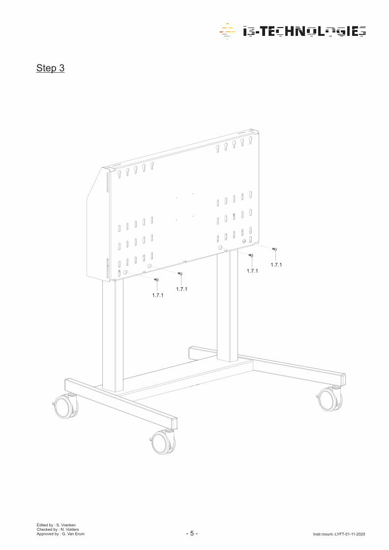
Step 3
Edited by : S. VrankenChecked by : N. VoldersApproved by : G. Van Erum Instr.mount.-LYFT-01-11-2020
1.7.11.7.1
1.7.11.7.1

- -6
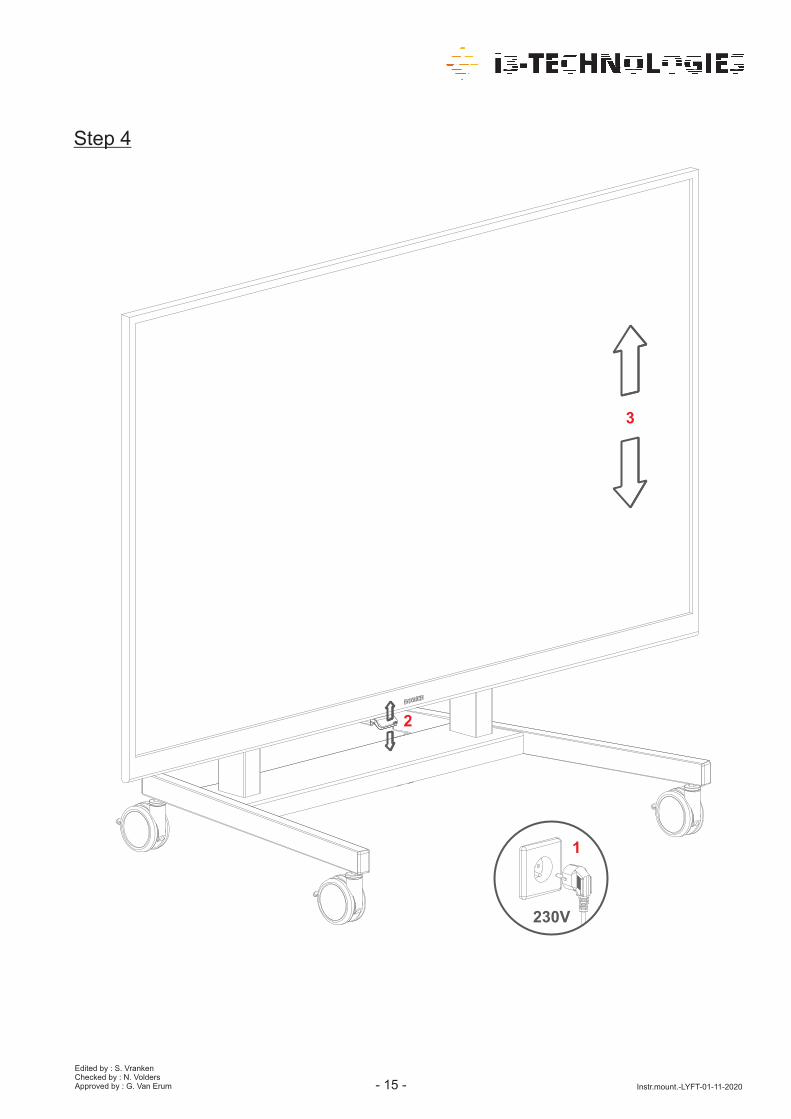
Step 4
Edited by : S. VrankenChecked by : N. VoldersApproved by : G. Van Erum Instr.mount.-LYFT-01-11-2020
1. .14
1. .4 2
1. .241.5
POWER STRIP(not included)
Note !!!
If go to LYFT A -ON after this step.the installation manual DDoption Add-on
1.5
- -7
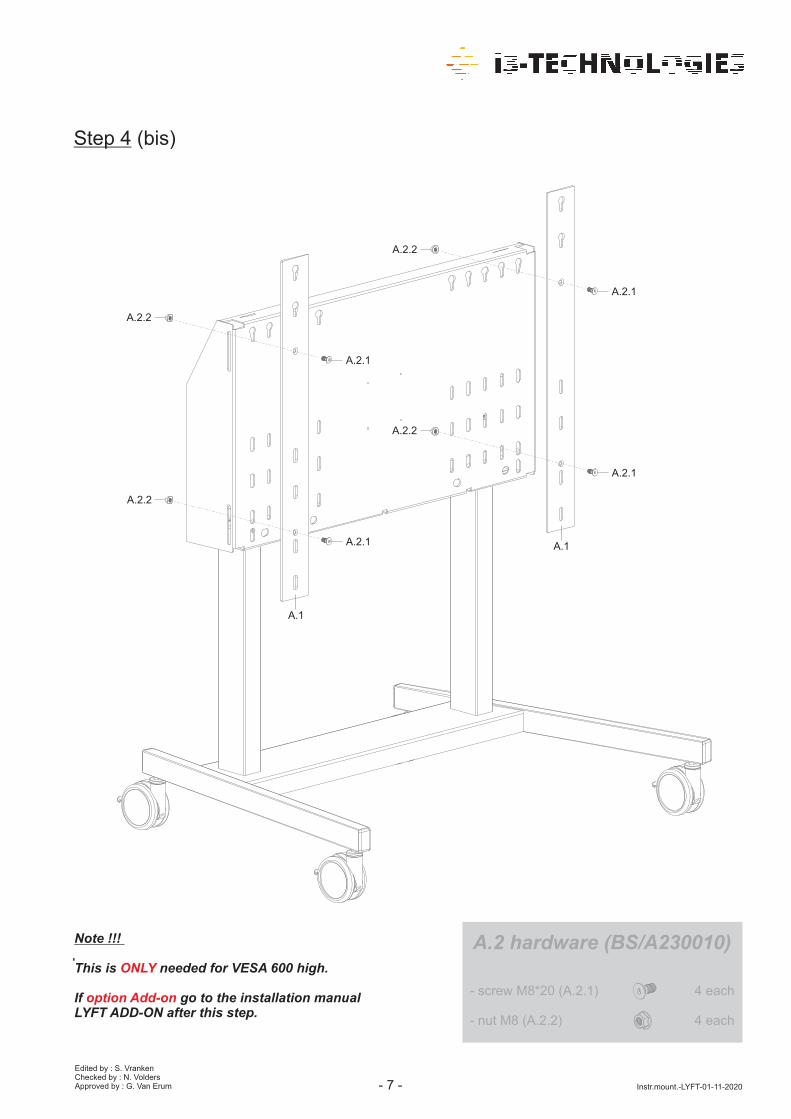
Step 4 (bis)
Edited by : S. VrankenChecked by : N. VoldersApproved by : G. Van Erum Instr.mount.-LYFT-01-11-2020
Note !!!
his is needed VESA 600 high.T forONLY
If go to the installation manualoption Add-onLYFT ADD-ON after this step.
A.2.2
A.2.2
A.2.2
A.2.2
A.2.1
A.2.1
A.2.1
A.2.1
A.1
A.1
A.2 hardware (BS/A230010)
- 8*20 (A. .1) eachscrew M 2 4
- nut M8 (A.2.2 each) 4
- -8
Edited by : S. VrankenChecked by : N. VoldersApproved by : G. Van Erum Instr.mount.-LYFT-01-11-2020
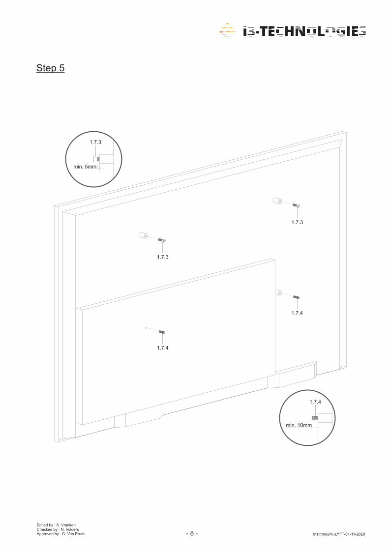
Step 5
1.7.4
1.7.3
1.7.3
1.7.4
min. mm5
min. mm10
1.7.3
1.7.4
- -9
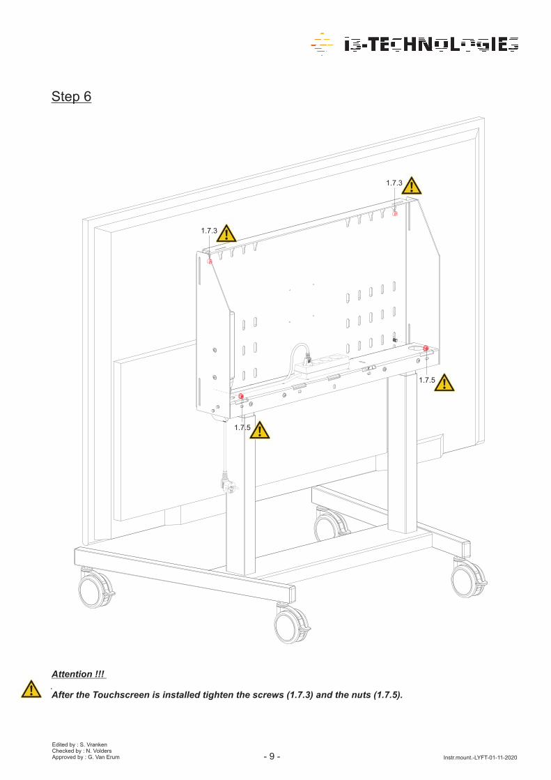
Step 6
Edited by : S. VrankenChecked by : N. VoldersApproved by : G. Van Erum Instr.mount.-LYFT-01-11-2020
Attention !!!
After the Touchscreen is installed tighten the (1.7.3) and the nuts (1.7. ).screws 5
1.7.3
1.7.3
1.7.5
1.7.5

Step 7
Edited by : S. VrankenChecked by : N. VoldersApproved by : G. Van Erum Instr.mount.-LYFT-01-11-2020
230V
2
3
1
- -10

- -11
Edited by : S. VrankenChecked by : N. VoldersApproved by : G. Van Erum Instr.mount.-LYFT-01-11-2020
2 OPTI. ON FRONT CONTROL (i3-TOUCH)
2.2
1.6.2 included with LYFT MOBILE packaging
1 6.. 1 pre-assembled on VESA-mount (1.3)
. hardware (BS/A226010)2 2
- * (2. .1) eachscrew M4 25 2 2
- ( .2) eachnut M4 2.2 2
- screw M3*8 ( . .3) 2 each2 2
2.1

- -12
Edited by : S. VrankenChecked by : N. VoldersApproved by : G. Van Erum Instr.mount.-LYFT-01-11-2020
Step 1
Note !!!
starting with step 1, shut down the system, remove the plug from the wall socket and demount /BEFOREunplug the control panel (1.6.1) from the VESA-mount (1.3).
2.2.2
2.2.1
2.2.2
2.2.2
1.6.1
1.6.2
2.1

- -13
Edited by : S. VrankenChecked by : N. VoldersApproved by : G. Van Erum Instr.mount.-LYFT-01-11-2020
2 2 3. .
2 2 3. .
Attention !!!
Before installing the pre-assembly front control panel, remove the existing screws and replace them withthe supplied screws (2.2.3).
Step 2

Step 3
Edited by : S. VrankenChecked by : N. VoldersApproved by : G. Van Erum Instr.mount.-LYFT-01-11-2020- -14
1. .6 1
- -15
Step 4
Edited by : S. VrankenChecked by : N. VoldersApproved by : G. Van Erum Instr.mount.-LYFT-01-11-2020
230V
2
3
1
- -16
Edited by : S. VrankenChecked by : N. VoldersApproved by : G. Van Erum Instr.mount.-LYFT-01-11-2020
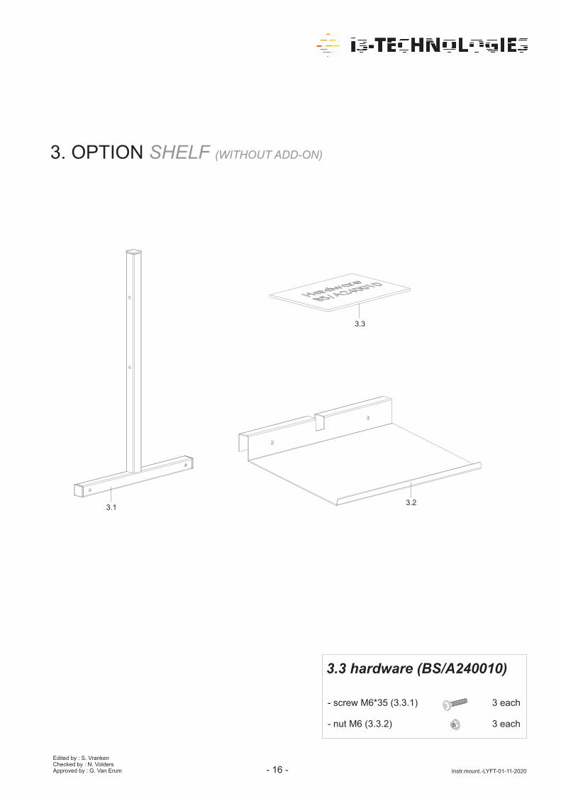
3. OPTION SHELF ( -ON)WITHOUT ADD
3 3.
. hardware (BS/A2 010)3 3 40
- *3 ( . .1) eachscrew M6 5 3 3 3
- ( .2) eachnut M6 3.3 3
3.23.1

- -17
Edited by : S. VrankenChecked by : N. VoldersApproved by : G. Van Erum Instr.mount.-LYFT-01-11-2020
Step 1
3.2
3.1
3 3. .1
3 3. .1
3.3.2
3.3.2

Step 2
Edited by : S. VrankenChecked by : N. VoldersApproved by : G. Van Erum Instr.mount.-LYFT-01-11-2020- -18
3.3.1
3.3.2

- -19
Edited by : S. VrankenChecked by : N. VoldersApproved by : G. Van Erum Instr.mount.-LYFT-01-11-2020
4 OPTION. COVER ( )ELECTRIFICATION
4.1

Step 1
Edited by : S. VrankenChecked by : N. VoldersApproved by : G. Van Erum Instr.mount.-LYFT-01-11-2020- -20
4.1
PADLOCK(not included)