m. gilinsky - nasa · internal designs application for inlet and nozzle airperformance improvement...
TRANSCRIPT
Internal Designs A plication for Inlet and Nozzle Aero ePformance I prove me nt
M. Gilinsky Hampton Universi Harnpton, VA
and
NASAGlenn Research Center, Cleveland,OH
36* AlAAIASM E/SA€/ASEE Joint Propulsion Conference
July 17-1 , 2000/H untsville, AL
For permission to copy or republish, contact ?he American InstItute of Aeronautlcs and Astronautlcs 370 L'Enfant Promenade, S.W., Washlngton, D.C. 20024
https://ntrs.nasa.gov/search.jsp?R=20040046151 2018-06-10T22:46:59+00:00Z
INTERNAL DESIGNS APPLICATION FOR INLET A N D NOZZLE A I R P E R F O R M A N C E I M P R O V E M E N T
M. Gilinskyt, Hampton University, Hampton, VA 23668
and I.M. Blankson'
NASA Glenn Research Center Cleveland, OH 44135
ABSTRACT
The following research results are based on develop- ment of an approach previously proposed by the authors for optimum nozzle design to obtain maximum thrust. The design was denoted a Telescope nozzle. A Telescope nozzle contains one or several internal designs of certain location, which are inserted at certain locations into a divergent conical or planar main nozzle near its exit. Such a design provides additional thrust augmentation over 20% by comparison with the optimum single nozzle of equivalent lateral area. What is more, recent experi- mental acoustic tests have discovered an essential noise reduction due to Telescope nozzles application. In this paper, some additional theoretical results are presented for Telescope nozzles and a similar approach is applied for aeroperformance improvment of a supersonic inlet. In addition, a classic gas dynamics problem of a simi- lar supersonic flow into a plate has been analyzed. In some particular cases, new exact analytical solutions are obtained for a flow into a wedge with an oblique shock wave. Numerical simulations were conducted for supersonuc flow into a divergent portion of a 2D or ax- isymmetric nozzle with several plane or conuical designs as well as into a 2D or axisymmetric supersonic inlet with a forebody. The 1st order Kryko-Godunov march- ing numerical scheme for inviscid supersonic flows was used. Several cases were tested using the NASA CFL3d code based on full Navier-Stokes equations. Numerical simulation results have confirmed essential benefits of Telescope design applications in propulsion systems.
I. INTRODUCTION
Several well-known experimental results show essen- tial acoustic benefits in the application of some untra- ditional nozzle designs. For example, nozzles with rect- angular or elliptic cross section in the supersonic part produce less jet noise than round nozzles designed for a fixed Mach number at the nozzle exit ( i.e. with uniform flow at the exit and pressure coinciding with the flight static pressure outside the exhausting jet). Thus, the theoretical perfectly shock free jets are "noisier" than
t Research Professor, Senior Member AIAA * Senior Scientist/Tectinologist, Associate Fellow AIAA
at least partially underexpanded (or overexpanded) jets with possible internal shocks. Moreover, the experimen- tal research of Ahuja, Krothapalli et al. [1,2] has shown that inserting disturbing elements into supersonic jet flow: slots, finger, tabs etc., can reduce jet noise (and screech tones) in spite of the presence numerous strong and weak shock waves. This contradicts the traditional view on the considered phenomenon. A reasonable ex- planation for these facts would be the appearance of more effective mixing and destruction of the regular cell-shock structure in the weakly underexpanded jet. Inside such a jet, the weak barrel-shaped shock waves are always present and these shock waves are the main sources of the oscillatory processes in the jet. In the reg- ular almost parallel ceannular mixing layers, unstable longitudinal waves are excited, and noise is produced in the fixed direction of the jet axis - 145'. Of course, the presence of shock waves in the jet exhaust, especially for a supersonic nozzle, can lead to some dangerous side ef- fects and performance penalties.
Developing previous ideas for jet noise reduction, two novel concepts were proposed in the papers [3-61. This first concept is denoted as the Telescope nozzle, for it consists of several internal nozzle surfaces that are arranged in a telescope fashion. The second concept is denoted as the Bluebell nozzle, based on the flower- like shape of its external jet plume. Bluebell nozzles utilize both chevrons and corrugation in its nozzle ge- ometry. Each concept is capable of achieving a thrust performance greater than the standard baseline conic or 2D plane convergent and convergent-divergent (CD) nozzles. The improved performance for Bluebell noz- zles occurs due to increase in nozzle internal surface area while maintaining nozzle-projected area equiva- lent to the baseline reference nozzle. Small scale and large scale acoustic tests of different modifications of Bluebell nozzles were conducted at the NASA Langley Research Center and Central AeroHydrodynamics In- stitute (TsAGI) in Moscow, Russia. These tests have shown essential acoustic benefits Bluebell design ap- plication in supersonic regimes as well as in subsonic regims. For example, the experimental tests of several Bluebell nozzle designs ([3]) have shown noise reduction
,
1
relative to a CD round nozzle with design exhaust Mach number M,=1.5. The best design provides an acoustic benefit near 4dB with about 1% thrust augmentation. Below, we consider only the first (Telescope) concept with the goal of the Telescope nozzle design optimiza- tion for the muximum nozzle thrust, with the intent application of this concept to propulsion systems, es- pecially, for a supersonic engine inlet. Detailed infor- mation about the second (Bluebell) concept is in the papers [3-61 and in the patent [7].
11. PLANE ELEMENT IN SUPERSONIC FLOW
2.1. The thrust on a plate element w i t h an oblique shock wave and Prandtl-Meyer rarefac- tion flow. A divergent flow can act on a plate or airfoil inserted into a flow so that a resulting force is directed against the flow. This effect is used for thrust by su- personic nozzles. Conversely, a uniform flow produces only drag for bodies and airfoils. Inserting a conical or wedge-shaped nozzle inside the divergent part of an ex- ternal nozzle so that the integral of the pressure on the low side of the inserted surface is greater than on the up- per side produces increased thrust. There is an optimal angle of the plate that provides the maximum thrust at each point of a divergent flow. The most efficient inter- nal design is produced from a pattern that looks like a telescope with extending tubes. The optimal number of internal designs is defined through dependence on the Mach number at the nozzle exit, Me. Telescoping de- signs must be located so that the compressible waves formed by interaction of a flow with this design would be passed on to the upper side of the next lower tele- scoping part. The best result will be produced by such a set if the external design inclination increases down- stream. Computations show that a significant thrust benefit from the Telescope nozzle occurs with an exter- nal telescoping design, using either wedge, conical or optimal contour shapes, and also in the case of a plug application.
This effect can be demonstrated by consideration of the classical steady supersonic flow which forms when an infinite uniform supersonic flow diverges at the de- viated wall (convex angle wall). The schematic wave picture of such a flow is shown in Figure 1. A super- sonic flow with Mach number, M = &Im >1 is flowing along a rectilinear wall EO. After point 0, the wall is turned at some angle 6,. The flow velocity increases in the centre wave so that all flow parameters depend only on the angle cp. All flow parameters can be calculated by:
P Sin2(Qcp), - = (1 - (1) 2 X ? = l + -
6 - 1 P o
wr = -sin(acp), 1 'WV = cos(qD) a
1 x sins=- 6 = a + ( p - - &I ' 2
(3)
(4)
where
c p O = c p o O + " C O (6) Here the angle cp is measured from the straight line cp = 0 which is inclined to the initial wall direction by the angle yo; 6 is the angle between local velocity and initial wall direction.
Let a plate element be inserted into this Prandtl- Meyer rarefaction wave. Then depending on this ele- ment's location and inclination to the local velocity vec- tor, W(wr,wY), two different cases are possible. The first, when the element is located in the uniform flow region (the region 5 in Figure 1). Then the flow at the plate is similar and the thrust (or drag) produced by this element can be calculated by relationships in the Prandtl-Meyer rarefaction wave (1-6) for one side of the plate and by relationships on the shock wave (BC) for the other side:
where /3 and 7 are local angles between the flow di- rection (the vector W) and the shock wave and plate respectively. This case is analyzed in paper [3]. It was shown that the optimal inclination of the plate de- pended on the local Mach number and flow direction. But these results were not connected with any fixed flow, so that the two given parameters, Mach number and angle of flow direction are independent. In the case of rarefaction flow, these parameters are dependent by relationships ( 1-6). Calculations show that maximal thrust is produced by the unit plate element when this plate is inclined to the initial wall direction of the angle, 7 - 100.
In the second case the plate is located in the rar- efaction wave and the flow at the plate is not similar. The unknown oblique shock wave is not rectilinear, and the flow behind it is not uniform and parallel to the plate direction. In some approximations, this problem has an analytical solution. For example, the flow on both sides of the plate can be calculated in acoustic ap- proximation for weak waves using an analytical or any numerical method for 2D flow.
2.2. Oblique shock relationship analysis. Some theoretical analysis of shock wave relationship (7) was conducted with the goal to simplify and increase the
2
efficiency of the numerical algorithms. Let a plate (or wedge) be located at the angle, -/ to the supersonic flow direction. It is well known that the formula (7) defines this angle implicitly through use of the angle, p, be- tween the shock wave and downstream flow direction. Usually, the plate or wedge angle, 7, is given, and the shock wave angle, p, is unknown, i.e. its value is cal- culated by iteration of (7) or by interpolation of the tabled curves y=F(,B, Ad,) where F is some function. Of course, explicit formulae are preferable, especially, in more complicated algorithms, which calculate this problem solution repeatedly as, for example, in mod- ern numerical schemes with the Riemann solver. The equation (7) can be transformed to a cubic equation of the variable y=f(p). For simplification, substitute also: x=tan2y, a = ( K + 1)/2, m=&!;2. Then this eqation be- comes:
Ay3 + By2 + cy+ D = 0 (8) where A=a( l+x), B=m-l+(m-2a)x, C=(a-%m)x, D=mx
Explicit solution of this equation can be given us ing Cordano formulae (see [8]). In accordance with the analysis of the coefficients in (8), we conclude that this equation has three real roots. The simpliest represen- tation of these roots can be given by introduction of the auxiliary angle. Only two positive roots are in the range of the variable y. The greater root corresponds to a subsonic value of shock wave inclination, and lower is for a supersonic value. Since these formulae for roots are combersome, we omit them in this paper.
Two important relationships can be found from (7) without use of its exact solution. The first is defi- nition of limit values for the angles 7 and p. They are determined at the maximum value of the function p = P(7), Le. using the relationship: dpldy = 0. Equating the derivative of the variable /3 on the right side in (7) to zero, we get the square equation for a variable z = sin2@:
K.Z2 - (a - 2m)z - ( 7 2 + am) = 0
and positive root is
2 = -(- K 2 l a - m+ /-) (9)
so that limited shock inclination ,Brim is calculated as P/im = asin(&) and the limited wedge inclination ylim is calculated using formulae ( 7 ) with prim on the right side. For hypersonic flows with Mach number, Mm = IX) (m=O) we have:
The corresponding curves for dependance of limit angles -/ and 0 on Mach number and specific heat ratio K are shown in Figures 2 which were calculated using (10) and (7).
The second relationship is for hypersonic Aows with Mach number, M , = 00. In this case, the solution comes to a solution of the square equation relative to variable, z = sin2@. Designate t=tany, then the roots of this equation are:
(11) 1 + ( K + 1)t f J1- ( K 2 - 1)tZ
2(1+ t 2 ) *1,2 =
where "p1us"sign corresponds to subsonic conditions and "minus" to supersonic condition. The set of well known "apple-like" curves for dependence angles p = F(7) for different specific heat ratios are shown in Figure 3. The black poins with numbers 1-11 correspond to limited values of these angles.
2.3. Optimum plate location. In common case, a plate (or airfoil) inserted into an inviscid supersonic flow produces a resulting force normal to the plate and its value and direction depend on the pressure difference on both sides of the plate. The nondimensional aero- dynamic characteristics of the plate, the thrust, Tn, or drag, CD, produced by this flow about the plate can be calculated with these four parameters: specific heat ra- tio K , flow Mach number, M,, an angle a between the flow and thrust direction, and the angle 7 between the flow and the plate. Schematic geometry and designa- tions for such a flow are shown in Figure 4a. An angle, y, is measured from the upstream flow direction. If 7 20 and less than the limited angle Trim, (05 y 5 ylim), the thrust (drag) is determined by the simple analyti- cal formulae using relationships for oblique shock waves and the Prandtl-Meyer rarefaction wave discussed in the previous sections. In this interval of the angle 7, for all another parameters there is an optimal value of the angle 7opi , which gives the thrust maximum value. Aerodynamic characteristics of the unit plane element in supersonic flow were calculated using the created code for a wide range of the parameters: k, M,, and a. Two examples are illustrated in Figures 4b,c by the curve families for the nondimensional variables (T, ,7') for Mach number n/r, = 2 and M , = 6 respectively. Numbers 1,2,3,4, and 5 at the curves correspond the angls, a = Oo,22.50,450,67.50, and 90°. Note, that for large attack angles to the thrust direction, a, maximum thrust is obtained at the limited angles, 71im.
Similar results were observed for another case that correspons to a pure Prandtl-Meyer flow at the turn- ing point of the 2 D nozzle wall. The schematic pic- ture of such Bow and designations are shown in Figure 5a. Tipical examples for Mach number, hIm = 1.5 and
3
3 are illustrated in Figure 5b,c. Here, the nondimen- sional thrust T, vs wall inclination angle, 7, for several slopes of the flow (or upstream wall) is given. Num- bers 1,2,3,4, and 5 on the curves correspond to angle a = 0", lo", 2O0, 30", and 40". Again, for small angles, a, there are maximum thrust values inside the interval 05 7 5 Yrj,,,, and for greater a, maximum thrust occurs at the limited value Trim. Similar results were observed with other Mach numbers.
111. TELESCOPE NOZZLE NUMERICAL SIMULATION RESULTS
The main numerical simulation results for Telescope nozzle based on the 1st order Krayko-Godunov march- ing scheme [9] for inviscid supersonic flows were dis- cribed in the papers [3,5]. Some of them will be illus- trated below. In particular, it was shown that by the standard deformation of single axisymmetric or 2D noz- zle it is possible to obtain only an insignificant thrust augmentation, even using optimal nozzle shape, i.e. N 1-4% by comparison with usual conical (wedge-shaped) nozzle. A Telescope nozzle can increase thrust signifi- cantly more.
3.1 Telescope nozzle geometry. Example of two possible Telescope nozzle embodiments are shown in Figure 7a and 7b. In Figure 7a, the external nozzle is constructed by giving the &xed contour z=z(x) in the zx-plane and a cross section contour is described by the super-elliptical equation:
(y/.(.))"'"' + (r/b(z))"(") = 1, 2 = f(2) n(z) = 2 + H ( z - E , ) * ne($ - $*)/(($e - z,) (12)
C(Z) = a(t)/b(x) = l+H(I-z*).ce(Z - ~.)/((te - 2,)
(13) where the Heaviside function H(x-t,) is defined: H(x- z.)=O if $0 5 2 5 z,, and H(x-z.)=l if Z, 5 t 5 ze. The subscripted indicies O,* and e correspond respec- tively to the nozzle inlet, throat and exit. The subsonic portion of the nozzle (from the inlet to the throat) has axisymmetric shape (a=b=l, n=2). In the supersonic portion (from the throat to the nozzle exit), a power n in (12) changes from the minimal throat value of 2 to the maximal exit value ne and an eccentricity c=a/b changes from the minimal throat value of 1 to the may- imal exit value ce. The nozzle contour z=f(x), in the plane of symmetry, y=O, is a cubic parabola in the sub- sonic part and then becomes rectilinear with the angle a = 10". For the Telescope nozzle in Figure 6a, the power n(x) increases from 2 to 10 downstream from the throat to the exit and two plane internal designs located symmetrically supported by the holders into the external design. In Figure 6b another style of the Telescope nozzle is shown. The external nozzle is de- scribed by a super-elliptical equation with constant val- ues n=2, a=b=l, and the internal design is described
4
by the same equation with a=l,b=O.5, i.e. cross section has an elliptical shape; the internal design is again sup- ported by holders to the external design. In the both cases, the nozzle contour in XZ-plane, z=f(x), contains rectilinear and round intervals with continuous inclina- tions in the points of discontinuous curvature.
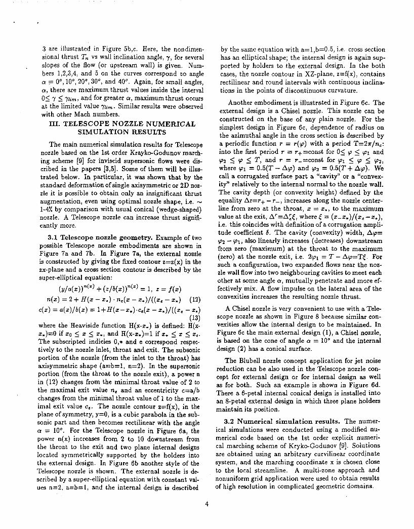
Another embodiment is illustrated in Figure 6c. The external design is a Chisel nozzle. This nozzle can be constructed on the base of any plain nozzle. For the simplest design in Figure 6c, dependence of radius on the azimuthal angle in the cross section is described by a periodic function r = r(p) with a period T=2?r/nc: into the first period r = r+=const for 05 p 5 pl and p2 5 cp 5 T , and r = r-=const for (PI 5 'p 5 972, where 91 = 0.5(T - Ap) and 972 = 0.5(T + Ap). We call a corrugated surface part a "cavity" or a "convex- ity" relatively to the internal normal to the nozzle wall. The cavity depth (or convexity height) defined by the equality Ar=r+ - r- , increases along the nozzle center- line from zero at the throat, z = $., to the maximum value at the exit, Ar=AZt, where ( = (z-z,)/(ze--t*), i.e. this coincides with definition of a corrugation ampli- tude coefficient 6 . The cavity (convexity) width, Ap= 972 - (PI, also linearly increases (decreases) downstream from zero (maximum) at the throat to the maximum (zero) at the nozzle exit, i.e. 2pl = T - Ap=TE. For such a configuration, two expanded flows near the noz- zle wall flow into two neighbouring cavities to meet each other at some angle a, mutually penetrate and more ef- fectively mix. A flow impulse on the lateral area of the convexities increases the resulting nozzle thrust.
A Chisel nozzle is very convenient to use with a Tele- scope nozzle as shown in Figure 8 because similar con- vexities allow the internal design to be maintained. In Figure 6c the main external design (l) , a Chisel nozzle, is based on the cone of angle a = 10" and the internal design (2) has a conical surface.
The Blubell nozzle concept application for jet noise reduction can be also used in the Telescope nozzle con- cept for external design or for internal design as well as for both. Such an example is shown in Figure 6d. There a 6-petal internal conical design is installed into an &petal external design in which three plane holders maintain its position.
3.2 Numerical simulation results. The numer- ical simulations were conducted using a modified nu- merical code based on the 1st order explicit numeri- cal marching scheme of Kryko-Godunov [9]. Solutions are obtained using an arbitrary curvilinear coordinate system, and the marching coordinate x is chosen close to the local streamline. A multi-zone approach and nonuniform grid application were used to obtain results of high resolution in complicated geometric domains.
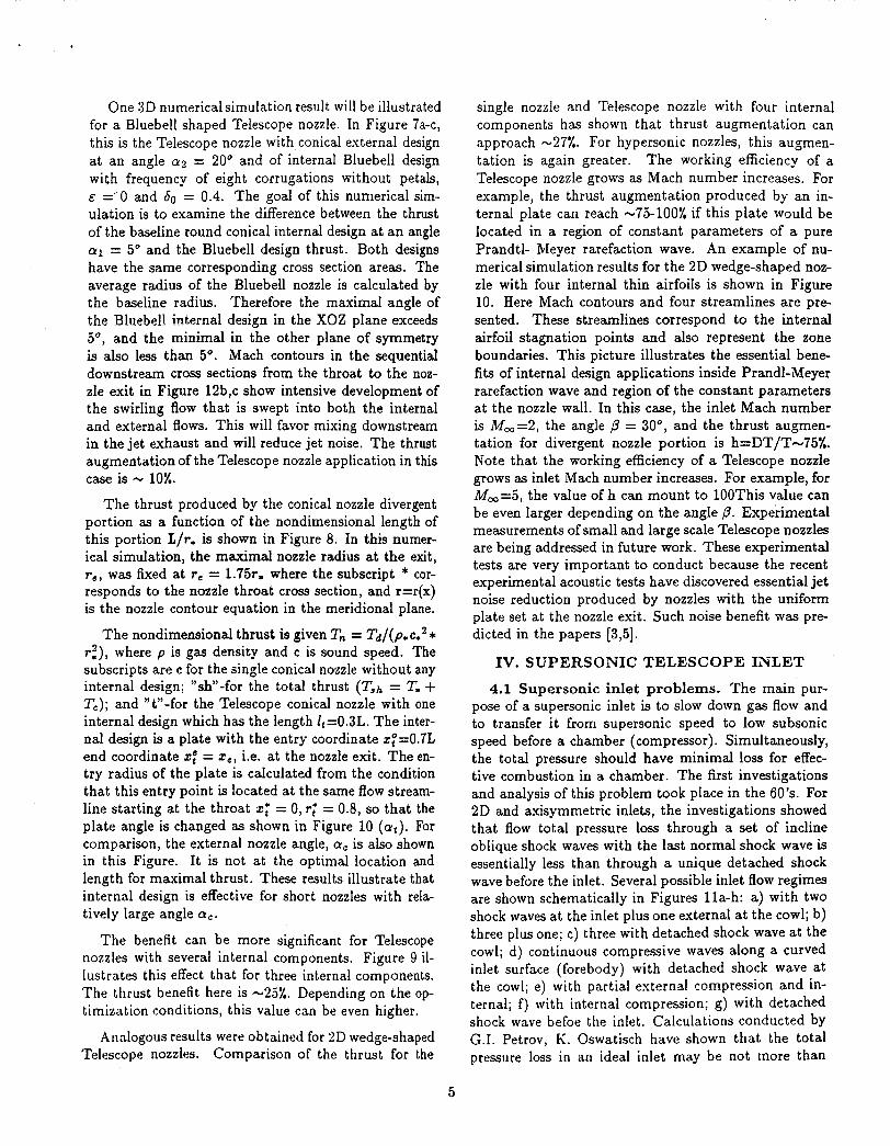
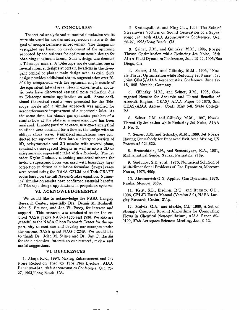
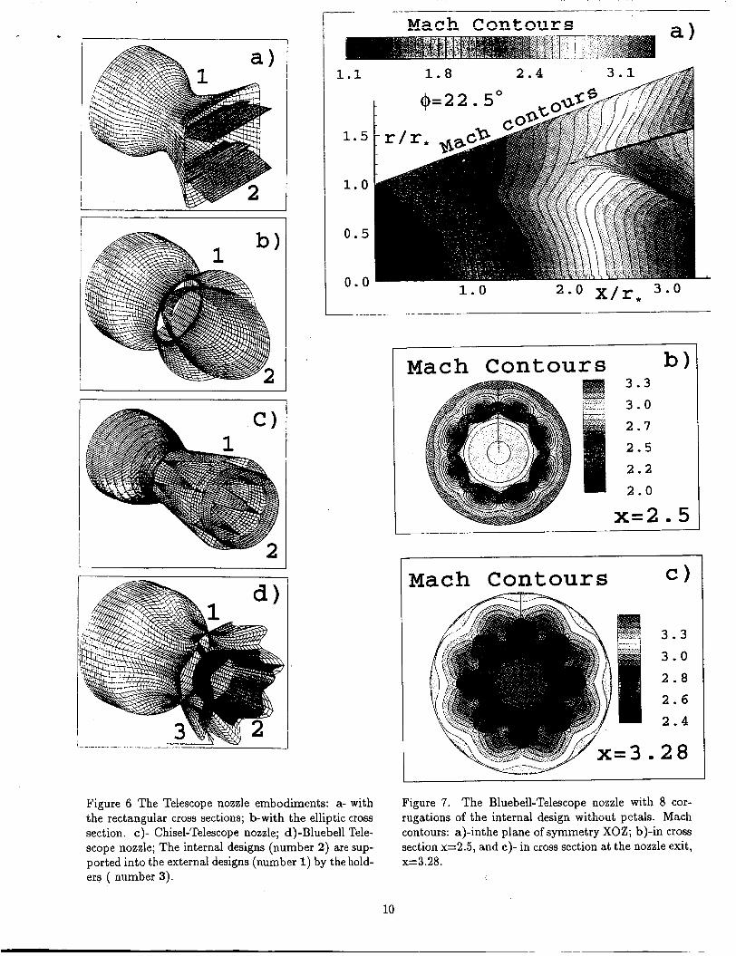
One 3D numerical simulation result will be illustrated for a Bluebell shaped Telescope nozzle. In Figure 7a-c, this is the Telescope nozzle with conical external design at an angle a2 = 20" and of internal Bluebell design with frequency of eight corrugations without petals, e ='0 and bo = 0.4. The goal of this numerical sim- ulation is to examine the difference between the thrust of the baseline round conical internal design at an angle a1 = 5" and the Bluebell design thrust. Both designs have the same corresponding cross section areas. The average radius of the Bluebell nozzle is calculated by the baseline radius. Therefore the maximal angle of the Bluebell internal design in the XOZ plane exceeds 5", and the minimal in the other plane of symmetry is also less than 5". Mach contours in the sequential downstream cross sections from the throat to the noz- zle exit in Figure 12b,c show intensive development of the swirling flow that is swept into both the internal and external flows. This will favor mixing downstream in the jet exhaust and will reduce jet noise. The thrust augmentation of the Telescope nozzle application in this case is - 10%.
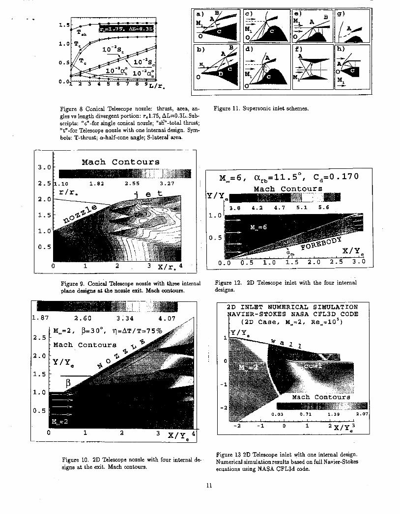
The thrust produced by the conical nozzle divergent portion as a function of the nondimensional length of this portion L/r, is shown in Figure 8. In this numer- ical simulation, the maximal nozzle radius at the exit, re, was fixed at re = 1.75r, where the subscript * cor- responds to the nozzle throat cross section, and r=r(x) is the nozzle contour equation in the meridional plane.
single nozzle and Telescope nozzle with four internal components has shown that thrust augmentation can approach -27%. For hypersonic nozzles, this augmen- tation is again greater. The working efficiency of a Telescope nozzle grows as Mach number increases. For example, the thrust augmentation produced by an in- ternal plate can reach -75-100% if this plate would be located in a region of constant parameters of a pure Prandtl- Meyer rarefaction wave. An example of nu- merical simulation results for the 2D wedge-shaped noz- zle with four internal thin airfoils is shown in Figure 10. Here Mach contours and four streamlines are pre- sented. These streamlines correspond to the internal airfoil stagnation points and also represent the zone boundaries. This picture illustrates the essential bene- fits of internal design applications inside Prandl-Meyer rarefaction wave and region of the constant parameters at the nozzle wall. In this case, the inlet Mach number is M,=2, the angle p = 30", and the thrust augmen- tation for divergent nozzle portion is h=DT/T-75%. Note that the working efficiency of a Telescope nozzle grows as inlet Mach number increases. For example, for M,=5, the value of h can mount to lOOThis value can be even larger depending on the angle p. Experimental measurements of small and large scale Telescope nozzles are being addressed in future work. These experimental tests are very important to conduct because the recent experimental acoustic tests have discovered essential jet noise reduction produced by nozzles with the uniform plate set at the nozzle exit. Such noise benefit was pre-
The nondimensional thrust is given T, = Td/(p,ce2* dicted in the papers [3,5]. r:), where p is gas density and c is sound speed. The subscripts are c for the single conical nozzle without any internal design; "sh-for the total thrust (Tsh = T, + T,); and "t"-for the Telescope conical nozzle with one internal design which has the length It=0.3L. The inter- nal design is a plate with the entry coordinate z,0=0.7L end coordinate xi = x,, Le. at the nozzle exit. The en- try radius of the plate is calculated from the condition that this entry point is located at the same flow stream- line starting at the throat z: = 0, r; = 0.8, so that the plate angle is changed as shown in Figure 10 ( C Y $ ) . For comparison, the external nozzle angle, a, is also shown in this Figure. It is not at the optimal location and length for maximal thrust. These results illustrate that internal design is effective for short nozzles with rela- tively large angle a,.
The benefit can be more significant for Telescope nozzles with several internal components. Figure 9 il- lustrates this effect that for three internal components. The thrust benefit here is -25%. Depending on the op- timization conditions, this value can be even higher.
Arialogous results were obtained for 2D wedge-shaped Telescope nozzles. Comparison of the thrust for the
IV. SUPERSONIC TELESCOPE INLET
4.1 Supersonic inlet problems. The main pur- pose of a supersonic inlet is to slow down gas flow and to transfer i t from supersonic speed to low subsonic speed before a chamber (compressor). Simultaneously, the total pressure should have minimal loss for effec- tive combustion in a chamber. The first investigations and analysis of this problem took place in the 60's. For 2D and &xisymmetric inlets, the investigations showed that flow total pressure loss through a set of incline oblique shock waves with the last normal shock wave is essentially less than through a unique detached shock wave before the inlet. Several possible inlet flow regimes are shown schematically in Figures lla-h: a) with two shock waves at the inlet plus one external a t the cowl; b) three plus one; c) three with detached shock wave at the cowl; d) continuous compressive waves along a curved inlet surface (forebody) with detached shock wave at the cowl; e) with partial external compression and in- ternal; f ) with internal compression; g) with detached shock wave befoe the inlet. Calculations conducted by G.I. Petrov, K. Oswatisch have shown that the total pressure loss in an ideal inlet may be not more than
5

-3-5% for a shock wave system with equal intensity. In real inlet flow, separation zones can be formed at the sharp change of centerbody inclination or at the point of interaction of the shock wave with the boundary layer at ,the forebody or cowl. This makes the inlet charac- teristics worse. Detailed analysis of the supersonic inlet problem is in G.N. Abromovitch’s book [lo]. Note that most of the optimization theories and numerical simula- tion methods for improving inlet efficiency do not take these effects into account.
Separation and inlet drag are important obstacles for inlet efficient work. To reduce these effects, applica- tion of 3D corrugated surfaces similar to those that were used for improving nozzle designs may be employed. For example, a star shaped forebody or its smooth modifica- tion can reduce forebody drag. Also, it is known from hydrodynamic stability theory (Lin C.C., and others) that 2D velocity distributions in boundary or mixing layers are less stable than corresponding distributions in 3D cases because there is one additional degree of freedom for perturbation amelioration. Semi-empirical separation criteria show the same phenomenon. Several unusual curvilinear surfaces were proposed and tested experimentally many years ago by Russian scientists. However, such shapes have not been used in the avia- tion industry and require further research. Preliminary estimations are very promising.
4.2 O p t i m u m cowl shape analysis. The impor- tant inlet problem is to reduce inlet drag, i.e. forebody and cowl. Our calculations, using analytical relation- ships for shck waves have shown, that inlet drag may be reduced through judicious choice of forebody and cowl location and shapees. A schematic draft of one possible configuration is shown in Figure 14h, where instead of turning oblique shock waves around a cowl front edge, a forebody corner point was used as the turning point. The problem is optimization of the length and angle of cowl front door for a 2D inlet of an air-breathing propul- sion system. A systems of three and four oblique shock waves forming at the designed inlet for fixed Mach num- ber with a one and double wedge-shaped forebody were analyzed. The leading edge of a cowl door is the point of crossiqg of two or three oblique shock waves and the last passes the forebody corner point. The last shock wave joins this corner point and back edge of the cowl door. The shock wave system compresses and turns the initial supersonic Row and again deflects it to the same initial direction. The forebody drag, Co, and total pressure losses , E = ( p , - p o e ) / p o , in the cross section behind the forebody corner point were calculated. Here p , and poe are the total pressures behind normal shock waves upstream of the inlet and behind the corner point. The results are presented as curves for IC[, and 0 (where p is an angle between flow and plane cowl door) in the
variables (cot ) and (Co, Mm) respectively. The main conclusion from this calculation is that for each Mach number there is an optimal value Popt 20 which pro- vides a maximum value for working efficiency param- eter of such 3 or 4 shocks inlet, = (Co * E ) - ’ . The main conclusion for this problem is that the frontal cowl cap can create the additional engine thrust, and wedge shaped forebody drag can be reduced up to 15-20%. Nu- merical simulations by K-G marching code have shown approximately the same estimations for axisymmetric or 2D inlet with a conical or wedge-shaped forebody nose. The benefits increase with increase a cone (wedge) angle and increase in flight Mach number.
4.3 Some numerical simulation results. The most previous untraditional nozzle designs discussed above can be employed for a supersonic inlet improvement. In particular, a Telescope nozzle and all results of theoret- ical analysis of this concept are useful. In this case, the energy of the turned flow along the forebody wall can be used for creation of additional thrust as in the previ- ous case with a cowl door. As in the first problem, the mutual locations, sizes and angles of the internal plates (thin airfoils) are very important for efficiency of the application. Optimal values of geometric parameters were determined from multi-parametric numerical sim- ulations based on the modified marching K-G code. The effect of four thin airfoils installed at the minimal crow section (nearby of the corner point) is illustrated Figure 12. Here Mach contours and corresponding streamlines are shown for the 2D Telescope inlet with a wedged fore- body. This design provides a forebody drag reduction of 25%.
Some previous designs were tested numerically with the purpose of upstream viscous effects influence to the main conclusions. Partially, viscows effects were counted using boundary layer correction in thrust cal- culation. These estimations were conducted on mid- dle size vehicles for low flight altitudes. Two numerical codes were used: the NASA LaRC CFLJD code [ll] and CRAFT-Tech code [12]. Both codes are based on an implicit upwind 2nd order numerical schemes (EN0 versions) for solution of the full unsteady and steady Navier-Stokes and Euler equations. An example of a such result is shown in Figure 13. For these conditions (high Mach and Reynolds numbers), the tests have con- firmed the main conclusions of Telescope nozzles and inlets efficiency which were made on the basis of an- alytical solutions and numerical simulations using the simplified marching scheme Krayko-Godunov [9].
Obviously, the same approach is applicable for other designs, such as transition sections inside variable cross section supersonic tunnels, blunt bodies with several ring-shaped sheets, projectiles, etc.
6
V. CONCLUSION
Theoretical analysis and numerical simulation results were obtained for nozzles and supersonic inlets with the goal of aeroperformance improvement. The designs in- vestigated are based on development of the approach proposed by the authors for optimum nozzle design for obtaining maximum thrust. Such a design was denoted a Telescope nozzle. A Telescope nozzle contains one or several internal designs at certain locations in the diver- gent conical or planar main design near its exit. Such design provides additional thrust augmentation over 20- 30% by comparison with the optimum single nozzle of the equivalent lateral area. Recent eqerimental acous- tic tests have discovered essential noise reduction due to Telescope nozzles application as well. Some addi- tional theoretical results were presented for the Tele- scope nozzle and a similar approach was applied for aeroperformance improvment of a supersonic inlet. At the same time, the classic gas dynamics problem of a similar flow at the plate in a supersonic flow has been analyzed. In some particular cases, new exact analytical solutions were obtained for a flow at the wedge with an oblique shock wave. Numerical simulations were con- ducted for supersonuc flow into a divergent portion of 2D, axisymmetric and 3D nozzles with several plane, conuical or corrugated designs as well as into a 2D or axisymmetric supersonic inlet with a forebody. The 1st order Kryko-Godunov marching numerical scheme for inviscid supersonic flows was used with boundary layer correction in thrust calculation formulae. Several cases were tested using the NASA CFL3d and Tech-CRAFT codes based on the full Navier-Stokes equation. Numer- ical simulation results have confirmed essential benefits of Telescope design applications in propulsion systems.
VI. ACKNOWLEDGEMENTS
We would like to acknowledge the NASA Langley Research Center, especially Drs. Dennis M. Bushnell, John S. Preisser, and Joe W. P a y , for interest and support. This research was conducted under the ex- pired NASA grants NAG-1-1835 and 1936, We also are grateful to the NASA Glenn Research Center for the op- portunity to continue and develop our concepts under the current NASA grant NAG-3-2249. We would like to thank Dr. John M. Seiner and Dr. Jay C. Hardin for their attention, interest to our research, review and useful suggestions.
VI. REFERENCES
1. Xhuja K.K., 1993, Mixing Enhancement and Jet Noise Reduction Through Tabs Plus Ejectors, AIAA Paper 93-4347, 15th Aeroacoustics Conference, Oct. 25- 27, 1993/Long Beach, CA.
2. Krothapalli, A. and King C.J., 1993, The Role of Streamwise Vortices on Sound Generation of a Super- sonic Jet, 15th AIAA Aeroacoustics Conference, Oct. 25-27, 1993/Long Beach, CA.
3. Seiner, J.M., and Gilinsky, M.M., 1995, Nozzle Thrust Optimization while Reducing Jet Noise, 26th AIAA Fluid Dynamics Conference, June 19-22,1995/San Diego, CA.
4. Seiner, J.M., and Gilinsky, M.M., 199.5, "Noz- zle Thrust Optimization while Reducing Jet Noise", 1st Joint CEAS/AIAA Aeroacoustics Conference, June 12- 15,1995, Munich, Germany.
Gilinsky, M.M., and Seiner, J.M., 1996, Cor- rugated Nozzles for Acoustic and Thrust Benefits of Aircraft Engines, CEAS/ AIAA Paper 96-1670, 2nd CEAS/AIAA Aeroac. Conf., May 6-8, State College, PA.
6. Seiner, J.M. and Gilinsky, M.M., 1997, Nozzle Thrust Optimization while Reducing Jet Noise, AIAA J, No. 3.
7. Seiner, J.M. and Gilinsky, M.M., 1999, Jet Nozzle Having Centerbody for Enhanced Exit Area Mixing, US Patent #5,924,632.
8. Brounshtein, I.N., and Semendyaev, K.A., 1981, Mathematical Guide, Nauka, Fizmatgiz, 718p.
9. Godunov, S.K. et al., 1976, Numerical Solution of Multidimensional Problems of Gas Dynamics, Moscow: Nauka, 1976,400~.
10. Abromovich G.N. Applied Gas Dynamics, 1976, Nauka, MOSCOW, 888p.
11. Krist, S.L., Biedron, R.T., and Rumsey, C.L., 1996, CFL3D User's Manual (Version 5.0), NASA Lan- gley Research Center, 311p.
12. Molvik, G.A., and Merkle, C.L. 1989, A Set of Strongly Coupled, Upwind Algorithms for Computing Flows in Chemical Nonequilibrium, AIAA Paper 89- 0199, 27th Aerospace Sciences Meeting, Jan. 9-12.
5.
7

. . - -
I P
I GI ,'
Figure 1. A similar flow in a Prandtl-Meyer rar- efaction wave; the thrust of the unit plate element (BD) in this wave. The regions and nomenclature: 1)- supersonic inviscid uniform flow at the rectilinear wall, 2)- steady rarefaction wave, pangle of the 1st family characteristic, a- local angle between this characteris- tic and a streamline; 3)-uniform flow at the plate be- hind'the-oblique shock wave (BC), @- angle between the plate element and shock wave; 4)-Prandtl-Meyer rarefaction flow at the plate element, 7-angle between this element and the streamline; 5)-uniform flow a t the wall behind its turn, &-turn angle.
20 40 .' 60 a" 80
Figure 3. Analytical solution for supersonic flow at the wedge with oblique shock wave for Mach number, At, = cc. Shock wave angle, /3 vs wedge angle, a.
0.25 0 . 5 0 . 7 5 1
8 5 i - - - - r - - - -;- -
1
I I
I I
I I I I
-1- -
- I - - -1- - - - -
Figure 2. Analytical solution for supersonic flow at the wedge with oblique shock wave: a)-Shock wave angle, P, vs Mach number function, M;? for different specific heat ratios: r(=I .O, 1.1, ...ll.9,2.0; b-Wedge angle, 7, vs Mi?; c)-Shock wave angle, PI vs wedge angle, 7.
8

I
J !
t ' 1
0 10 I I I I 1 1 2 b ,
I I
Figure 4. Unit plane element thrust, T,, vs flow angle a, plate slope, Y, and flow Mach number, Adm; Analytical solution for supersonic flow at the plate with oblique shock wave and Prandtl-bIeyer rarefaction wave: a)- Draft and designations; b) and c)- nondimensional thrust vs plate slope, Y for Mm=2 and 6 respectively. Nunibers: 1,2,3,4, and 5 are for flow attack angle a=O.O, 22.5, 45.0, 67.5, and 90.0 (deg.).
T
I I
Figure 5. Unit plane element thrust, Tn, vs flow angle y- , plate slope, a, and flow Mach number, M,; Analytical solution for supersonic flow at the turning wall with the Prandtl-kIeyer rarefaction wave: a)- Draft and designations; b) and c)- nondimensional thrust vs plateslope, a for hfW=1.5 and 3 respectively. Numbers: 1,2,3,4, and 5 are for flow attack angle ym=O, 10, 20, 30, and -LO (dey.).
9
1.1 1.8 2.4 3.1
1.5
1.0
0.5
n n v . v - 1.0
Mach Contours b) 3 . 3
3.0 2 . 7
2.5 2.2 2.0
x=2.5
Figure 6 The Telescope nozzle embouLments: a- with the rectanguiar cross sections; b-with the elliptic cross section. c)- Chisel-Telescope nozzle; d)-Bluebell Tele- scope nozzle; The internal designs (number 2) are sup- ported into the external designs (number 1) by the hold- ers ( number 3).
10
Mach Contours c)
Figure 7. The Bluebell-Telescope nozzle with 8 cor- rugations of the internal design without petals. Mach contours: a)-inthe plane of symmetry XOZ; b)-in cross section x=2.5, and c) - in cross section at the nozzle exit, x=3.28.
. * 1
1.5
1.
0 .
0 .
0
5
'1 2 3 4 5 6 7 8 9~/ , . ,
I E I ' 'I
Figure 8 Conical Telescope nozzle: thrust, area, an- gles vs length divergent portion: r,1.75, AL=O.3L. Sub- scripts: "c"-for single conical nozzle; "sk?'-total thrust; "t"-for Telescope nozzle with one internal design. Sym- bols: T-thrust; a-half-cone angle; S-lateral area.
- 1 - c
Mach Con tour s
1.82 2.55 3.27 I I 2.0
1.5
1 . 0' 0.5
0 1 2
Figure 9. Conical Telescope nozzle with three internal plane designs at the nozzle exit. Mach contours.
L. 87 2.60 3.34 4.07
1 M _ = 2 , P=3O0, 2.5
2.0
1.5
1.0
0.5
Mach Contours
0 1 2 X/Ya4
Figure 10. 2D Telescope nozzle with four internal de- signs at the exit. Mach contours.
Figure 11. Supersonic inlet schemes.
0 M , = 6 , a,,=11.5 , C,=O. 170 Mach Contours
3.8 4.2 4.7 5.1 5.6 1.0
0.5
0.0 0.5 1.0 1.5 2.0 2.5 3 . ' "
Figure 12. 2D Telescope inlet with the four internal designs.
2D INLET NUMERICAL SIMULATION AVIER-STOKES NASA CFL3D CODE
(2D Case, ~ _ = 2 , R e _ = 1 0 5 )
1
1 0
-1
-2
Figure 13 2D Telescope inlet with one internal design. Numerical simulation results based on full Navier-Stokes ecuations using NASA CFL3d code.
11