m. n. m. allam m. sobhy bending analysis of fg ... · bending analysis of fg viscoelastic sandwich...
TRANSCRIPT

Acta Mech 212, 233–252 (2010)DOI 10.1007/s00707-009-0252-6
Ashraf M. Zenkour · M. N. M. Allam · M. Sobhy
Bending analysis of FG viscoelastic sandwich beamswith elastic cores resting on Pasternak’s elastic foundations
Received: 30 April 2009 / Revised: 14 September 2009 / Published online: 27 November 2009© Springer-Verlag 2009
Abstract The investigation of bending response of a simply supported functionally graded (FG) viscoelasticsandwich beam with elastic core resting on Pasternak’s elastic foundations is presented. The faces of thesandwich beam are made of FG viscoelastic material while the core is still elastic. Material properties aregraded from the elastic interfaces through the viscoelastic faces of the beam. The elastic parameters of thefaces are considered to be varying according to a power-law distribution in terms of the volume fraction ofthe constituent. The interaction between the beam and the foundations is included in the formulation. Numer-ical results for deflections and stresses obtained using the refined sinusoidal shear deformation beam theoryare compared with those obtained using the simple sinusoidal shear deformation beam theory, higher- andfirst-order shear deformation beam theories. The effects due to material distribution, span-to-thickness ratio,foundation stiffness and time parameter on the deflection and stresses are investigated.
1 Introduction
Sandwich structures are often found in aerospace applications such as in the skin of wings, vertical fin torquebox, aileron, spoilers, etc. The advantages of these structures are that they provide high specific stiffness andstrength-to-weight ratios, good fatigue properties, good thermal and acoustical insulation and ease of mass pro-duction [1]. Recently, sandwich construction becomes even more attractive due to the introduction of advancedcomposite materials for the faces and the core. Considerable effort has been devoted to study viscoelastic sand-wich beam problems, with relatively little work directed toward developing numerical models that might beapplicable to more general beams and support conditions.
The damping behavior of a 0◦ laminated sandwich composite beam inserted with a viscoelastic layer isinvestigated by Yim et al. [2]. Barbosa and Farage [3] studied a sandwich viscoelastic beam based on a finite ele-ment model. In this work, an assessment of a time-domain formulation for numerical modelling of viscoelasticmaterials was made. This formulation is based on a second-order time-domain realization of Laplace-domain
A. M. Zenkour (B) · M. SobhyDepartment of Mathematics, Faculty of Science,Kafr El-Sheikh University, Kafr El-Sheikh 33516, EgyptE-mail: [email protected]
M. N. M. AllamDepartment of Mathematics, Faculty of Science,Mansoura University, Mansoura 35516, Egypt
Present address:A. M. ZenkourDepartment of Mathematics, Faculty of Science,King Abdul Aziz University, P. O. Box 80203, Jeddah 21589, Saudi Arabia

234 A. M. Zenkour et al.
motion equations. Bekuit et al. [4] presented a quasi-two-dimensional finite element formulation for the staticand dynamic analysis of sandwich viscoelastic beams that are composed of three layers. Nayfeh [5] developeda model to study the vibration parallel to the plane of lamination of a symmetric five-layer elastic–viscoelasticsandwich beam. The dynamic stability of a rotating composite beam with a viscoelastic core subjected to axialperiodic loads was investigated by Lin and Chen [6] using the finite element method. In Yan et al. [7], thetwo-dimensional problem of a simply supported laminated orthotropic strip with viscoelastic interfaces understatic loading was investigated. Barkanov et al. [8] employed the finite element method to analyze the transientresponse of sandwich beams, plates and shells with viscoelastic layers under impulse loading. Galucio et al. [9]presented a finite element formulation for transient dynamic analysis of sandwich beams with embedded visco-elastic material using fractional derivative constitutive equations. In their analysis, the sandwich configurationis composed of a viscoelastic core sandwiched between elastic faces. Analysis and calculating approaches asto sandwich viscoelastic beams may also be found in references [10–13].
In the above conventional sandwich structures, homogeneous elastic and viscoelastic layers are bondedtogether to obtain enhanced mechanical properties. However, the sudden change in material properties acrossthe interfaces among different materials can result in large interlaminar stresses. To overcome these adverseeffects, a new class of advanced inhomogeneous composite materials, composed of two or more phases withdifferent material properties and continuously varying composition distribution, has been developed which isreferred to as functionally graded materials (FGMs). Such materials were introduced as to take advantage ofthe desired material properties of each constituent material without interface problems.
The mechanical properties of FGMs are often being represented in the exponentially graded form [14–16]and power-law variations one [17–26]. Reddy [22] analyzed the static behavior of FG rectangular plates basedon his third-order shear deformation plate theory. Reddy and Chin [23] studied the dynamic thermoelasticresponse of FG cylinders and plates. In Reddy and Cheng [24], three-dimensional thermomechanical defor-mations of simply supported, FG rectangular plates were studied by using an asymptotic method. A new beamelement has been developed to study the thermoelastic behavior of FG beam structures by Chakraborty et al.[27] using the first-order shear deformation theory. A crack in a viscoelastic strip of an FGM under tensileloading conditions was studied by Jin and Paulino [28]. More reports on FG structures may also be found inthe literature, such as Refs. [29–31].
Although there are research works reported on general FG structures, studies related to FGM sandwichstructures are few in number. Zenkour [17,18] employed the sinusoidal shear deformation plate theory tostudy the bending response, buckling and free vibration of a simply supported functionally graded sandwichplate. Three-dimensional finite element simulations for analyzing low velocity impact behavior of sandwichbeams with a functionally graded core were conducted by Etemadi et al. [32]. Anderson [33] presented ananalytical three-dimensional elasticity solution method for a sandwich composite with a functionally gradedcore subjected to transverse loading by a rigid spherical indentor. Ávila [34] proposed a failure mode criterionfor piece-wise functionally graded sandwich beams and compared it against experimental data. In Bhangaleand Ganesan [35], the buckling and vibration of a FGM sandwich beam having viscoelastic layer was studiedin thermal environment by using a finite element formulation.
Beams resting on elastic foundations have wide applications in modern engineering and pose great techni-cal problems in structural design. This motivated many researchers to analyze the behavior of beam structureson various types of elastic foundations. Thermo-mechanical vibration analysis of FG sandwich beams restingon variable elastic foundations was investigated by Pradhan and Murmu [36]. Ying et al. [37] presented exactsolutions for bending and free vibration of functionally graded beams resting on Winkler-Pasternak elasticfoundations. Aköz and Kadioglu [38] studied circular beams with variable cross-sections on elastic foundationsunder arbitrary loading using the finite element method and using the Winkler’s hypothesis for the foundation.Chen et al. [39] proposed a mixed method, which combined the state space method and the differential quadra-ture method, for bending and free vibration of arbitrarily thick beams resting on Pasternak’s elastic foundations.Natural frequencies and buckling stresses of a deep beam-column on two-parameter elastic foundations wereanalyzed by Matsunaga [40] using a one-dimensional higher order theory and taking into account the effectof shear deformation depth change and rotatory inertia. Sato et al. [41] presented the mathematical hypothesisthat a beam on equidistant elastic supports can be considered as a beam on an elastic foundation in staticand free vibration problems. Tsiatas [42] has presented the solution of the nonlinear problem of non-uniformbeams on nonlinear triparametric elastic foundations.
In this article, we restrict our attention on the FG viscoelastic sandwich beam with elastic core, which hasfound application in functionally graded materials. The present beam is symmetric about its mid-plane andresting on Pasternak’s elastic foundations. The faces are considered as FG viscoelastic material whereas the

Bending analysis of FG viscoelastic sandwich beams 235
core is assumed to be elastic. The elastic properties of the faces are considered to vary according to power-lawvariations. The refined sinusoidal shear deformation beam theory (RSBT) (see [14,20]) is used for the bendingresponse of the present beam resting on Pasternak’s elastic foundations. One of the advantages of this theory isthat the effects of normal and shear deformation are both included. To investigate this effect, the convergenceof the deflection and stresses are compared with those obtained using the simple sinusoidal shear deforma-tion beam theory (SSBT), the higher-order shear deformation beam theory (HOBT) and the first-order sheardeformation beam theory (FOBT). The effective moduli methods are used to solve the governing equations.The effects of the foundations on the FG viscoelastic sandwich beams are included in the formulation with atwo-parameter Pasternak model.
2 Problem formulation
Figure 1 shows an elastic–viscoelastic FG beam of length a, width b and thickness h. Rectangular Cartesiancoordinates xi are used to describe infinitesimal deformations of a three-layer viscoelastic sandwich beam.The mid-plane of the composite sandwich beam is defined by x3 = 0. The vertical positions of the bottom andtop, and of the two interfaces between the layers are denoted by h0 = −h/2, h1, h2, h3 = h/2. The faces aremade of FG viscoelastic material while the core is still elastic. The material properties vary smoothly in thex3 direction from the interfaces (x3 = h1 and x3 = h2) to the outer surfaces of the faces (x3 = ±h/2).
It is assumed that the top surface of the FG viscoelastic sandwich beam is subjected to sinusoidal dis-tribution load q(x) and the lower one is supported by two-parameter elastic foundations. In this model, theboundary conditions on the beam surfaces are:
σ3 = K1w − K2w,11, σ5 = 0 at x3 = h0;σ3 = −q(x), σ5 = 0 at x3 = h3,
(1)
where K1 is Winkler’s foundation stiffness while K2 is the shear stiffness of the elastic foundation and thecomma followed by index j , for example, denotes the differentiation with respect to the position x j ( j = 1, 3)of material particle. Here, we replace the indices xx, zz and zx of the stresses and strains by 1, 3 and 5,respectively.
The stress–strain relationships accounting for transverse shear deformation in the beam coordinates canbe written as
⎧⎪⎨
⎪⎩
σ1
σ3
σ5
⎫⎪⎬
⎪⎭
(n)
=⎡
⎢⎣
c11 c13 0c13 c33 00 0 c55
⎤
⎥⎦
(n)⎧⎪⎨
⎪⎩
ε1
ε3
ε5
⎫⎪⎬
⎪⎭, (2)
or
{σ }(n) = [c(x3)](n){ε}, (n = 1, 2, 3). (3)
The elastic stiffness coefficients are assumed to vary in the x3 direction. Using the power-law index distribution,the elasticity matrix for each layer can be written as
[c(x3)](n) = [cv] + ([ce] − [cv]) V (n), (4)
3x
a3
h
h
0h
1h
2h
1x
Viscoelastic
Viscoelastic
Elastic core
Shear layer ( 2k )
Winkler's springs ( 1k )
Fig. 1 Geometry of the FG viscoelastic sandwich beam resting on Pasternak’s elastic foundations

236 A. M. Zenkour et al.
where [cv] and [ce] represent the matrix of viscoelastic and elastic parameters, respectively. These matricesare defined as
[ci ] = Ei
1 − ν2i
⎡
⎢⎣
1 νi 0νi 1 0
0 0 1−νi2
⎤
⎥⎦, (i = e, v), (5)
where Ee and νe are Young’s modulus and Poisson’s ratio of the elastic material and they take constant values.The viscoelastic modulus Ev and the corresponding Poisson’s ratio νv may be given in terms of the coefficientof volume compression K and the kernel of the relaxation function ω(t) = ω by
Ev(t) = 9K ω
2 + ω, νv(t) = 1 − ω
2 + ω. (6)
The volume fraction V (n) follows a simple power-law through the thickness of the sandwich beam faceswhile it equals unity in the core layer. It reads [17,18]
V (1) =(
x3 − h0
h1 − h0
)m
, h0 ≤ x3 ≤ h1, (7)
V (2) = 1, h1 ≤ x3 ≤ h2, (8)
V (3) =(
x3 − h3
h2 − h3
)m
, h2 ≤ x3 ≤ h3, (9)
where m denotes the power-law index (0 ≤ m ≤ ∞). The core layer is independent of the value of m, whichmakes it fully elastic layer, whereas the value of m equal to zero represents a fully elastic beam. The abovepower-law assumption given in Eqs. (7) and (9) reflects a simple rule of mixtures used to obtain the effectiveproperties of the elastic–viscoelastic beam faces (see Fig. 1). Note that the volume fraction of the elastic mate-rial is high near the interfaces, and that of the viscoelastic one is high near the bottom and the top surfaces ofthe beam. In addition, Eqs. (7)–(9) indicate that the top and bottom surfaces of the beam are viscoelastic-richwhile the bottom (x3 = h1) and top (x3 = h2) surfaces of the core are elastic-rich.
The displacements of a material point located at (x1, x3) in the beam may be written as follows:
{u1
u3
}
={
u
w
}
+ α x3
{w,1
0
}
+{ψ ϕ1
βψ,3 ϕ3
}
, (10)
where u and w denote the in-plane and transverse displacements of points on the neutral axis of the beam, ϕ1represents the rotation of a transverse normal about the x2-axis, ϕ3 is an additional undetermined function ofx1. All of the generalized displacements (u, w, ϕ1, ϕ3) are functions of x1.
The above displacement field gives the following theories:
• Refined sinusoidal beam theory (RSBT): α = −1, β = 1, ψ(x3) = h sin(πx3/h)/π .• Simple sinusoidal beam theory (SSBT): α = −1, β = 0, ψ(x3) = h sin(πx3/h)/π .• Higher-order beam theory (HOBT): α = −1, β = 0, ψ(x3) = x3
[1 − 4x2
3/3h2].
• First-order beam theory (FOBT): α = β = 0, ψ(x3) = x3.
The corresponding strain components associated with the displacement field in Eq. (10) are
⎧⎨
⎩
ε1ε3ε5
⎫⎬
⎭=
⎧⎨
⎩
e10e5
⎫⎬
⎭+ x3
⎧⎨
⎩
ζ00
⎫⎬
⎭+
⎧⎨
⎩
ψ η1ψ,33 η3
ψ,3 η5
⎫⎬
⎭, (11)
where
e1 = u,1, ζ = αw,11, η1 = ϕ1,1,
η3 = β ϕ3, e5 = (α + 1)w,1, η5 = ϕ1 + β ϕ3,1.(12)

Bending analysis of FG viscoelastic sandwich beams 237
The principle of virtual work in the present study yields
∫
⎡
⎢⎣
+h/2∫
−h/2
(σ(n)1 δε1 + σ
(n)3 δε3 + σ
(n)5 δε5
)dx3 + (
K1w − K2w,11 − q)δw
⎤
⎥⎦d = 0, (13)
orL∫
0
[Nδe1 + Qδe5 + Sδη3 + Rδη5 + Mδζ + Pδη1 + (
K1w − K2w,11 − q)δw
]bdx1 = 0, (14)
where N , Q, S, R, M and P are the stress resultants which can be expressed as
(N , M, P) =3∑
n=1
hn∫
hn−1
(1, x3, ψ)σ(n)1 dx3, S =
3∑
n=1
hn∫
hn−1
ψ,33σ(n)3 dx3,
(Q, R) =3∑
n=1
hn∫
hn−1
K (1, ψ,3)σ(n)5 dx3,
(15)
where K is the shear correction factor of FOBT and it is fixed to be 5/6; hn and hn−1 are the top and bottomx3-coordinates of the nth layers.
3 Governing equations
The governing equations of the equilibrium associated with the displacement field in Eq. (10) are
N,1 = 0,
α M,11 + (α + 1)Q,1 + K1w − K2w,11 − q = 0,
P,1 − R = 0,
β (P,11 − S) = 0.
(16)
Using Eqs. (2) and (15), the force and moment resultants can be related to the total strains in the followingequations:
⎧⎪⎪⎪⎨
⎪⎪⎪⎩
N
M
P
S
⎫⎪⎪⎪⎬
⎪⎪⎪⎭
=⎡
⎢⎣
F11 F12 F13 F14F22 F23 F24
F33 F34symm. F44
⎤
⎥⎦
⎧⎪⎪⎪⎨
⎪⎪⎪⎩
e1
ζ
η1
η3
⎫⎪⎪⎪⎬
⎪⎪⎪⎭
,
{Q
R
}
=[
H11 00 H22
]{e5
η5
}
.
(17)
The elements of matrices [F] and [H ] are given as follows:⎡
⎣F11 F12 F13
F22 F23symm. F33
⎤
⎦ =3∑
n=1
hn∫
hn−1
c(n)11
⎡
⎣1x3ψ
⎤
⎦[1 x3 ψ
]dx3,
{F14, F24, F34} =3∑
n=1
hn∫
hn−1
c(n)13 {1, x3, ψ}ψ,33 dx3, F44 =3∑
n=1
hn∫
hn−1
c(n)33 (ψ,33)2dx3,
{H11, H22} =3∑
n=1
hn∫
hn−1
c(n)55 ψ,3{1, ψ,3}dx3.
(18)

238 A. M. Zenkour et al.
Substituting Eq. (17) into Eq. (16), we obtain the following equations for all theories:
F11∇2u + F12α∇2w,1 + F13∇2ϕ1 + F14βϕ3,1 = 0,
α(F12∇2u,1 + F22α∇2w,11 + F23∇2ϕ1,1 + F24β∇2ϕ3)+ [(α + 1)2 H11 + K2]∇2w − K1w + q = 0
(19)F13∇2u + F23α∇2w,1 + F33∇2ϕ1 + F34βϕ3,1 − H22(ϕ1 + βϕ3,1) = 0,
β(F14u,1 + F24α∇2w + F34ϕ1,1 + F44βϕ3)− H22β(ϕ1,1 + β∇2ϕ3) = 0.
For further computational reasons, the converted expressions of the stresses as functions of the volume fractionV n are also recorded. They read
σ(n)1 = (φ(n) + φ(n))(u,1 + α x3w,11 + ψ ϕ1,1)+ (φ(n)νv + φ(n) νe)(βψ,33 ϕ3), (20)
σ(n)3 = (φ(n)νv + φ(n) νe)
(u,1 + α x3w,11 + ψ ϕ1,1
) + (φ(n) + φ(n))β ψ,33 ϕ3, (21)
σ(n)5 = 1
2
[(1 − νv)φ
(n) + (1 − νe)φ(n)
] [(1 + α)w,1 + (ϕ1 + β ϕ3,1)ψ,3
], (22)
where
φ(n) = (1 − V (n))Ev1 − ν2
v
, φ(n) = V (n)Ee
1 − ν2e. (23)
4 Exact solutions for FGMs sandwich beams
In order to show the applicability and reliability of the present refined sinusoidal shear deformation beamtheory for the analysis of transverse normal and shear deformations in beams, a simply supported FGMssandwich viscoelastic beam resting on two-parameter elastic foundations is analyzed. The following boundaryconditions for all theories are assumed:
w = βϕ3 = N = αM = P = 0 at x1 = 0, a. (24)
Following the Navier solution procedure, displacement components and the external force for the case ofsinusoidally distributed load may be expressed as
⎧⎪⎪⎪⎨
⎪⎪⎪⎩
u
w
ϕ1
ϕ3
⎫⎪⎪⎪⎬
⎪⎪⎪⎭
=
⎧⎪⎪⎪⎨
⎪⎪⎪⎩
U cos(λx1)
W sin(λx1)
�1 cos(λx1)
�3 sin(λx1)
⎫⎪⎪⎪⎬
⎪⎪⎪⎭
, (25)
q = q0(t) sin(λx1), (26)
whereλ = π/a and U, W, �1 and�3 are arbitrary parameters. Note that q0(t) is a transient function accordingto the viscoelastic response of the bending problem.
With the help of Eqs. (25) and (26), Eq. (19) becomes
[A]{�} = { f }, (27)
where {�} and { f } denote the columns
{�}T = {U, W, �1, �3},{ f }T = {0, q0(t), 0, 0}, (28)
and the elements Ai j = A ji of matrix [A] are given by:
A11 = λ2 F11, A12 = αλ3 F12, A13 = λ2 F13, A14 = −βλF14,
A22 = α2λ4 F22 − [(1 + α)2 H11 − K2
]λ2 + K1,
A23 = αλ3 F23, A24 = −α βλ2 F24,
A33 = λ2 F33 + H22, A34 = −βλ (F34 − H22),
A44 = β2(F44 + λ2 H22).
(29)

Bending analysis of FG viscoelastic sandwich beams 239
5 Method of time-dependent solution
For a given set of values of ω, the corresponding elastic solution is obtained numerically with q0(t) = q0 whereq0 is a constant. In the elastic composites, the stresses are functions of x1, x3 and ω, while in the viscoelasticcomposites they are operator functions of x1, x3 and time t . According to Illyushin’s approximation method[43] (see also [44,45]), the stresses σ (n)i , i = 1, 3, 5 can be represented in the form
σ(n)i (x1, x3, ω) =
5∑
j=1
�(n)i j (x1, x3)� j (ω), (30)
where � j (ω) are some known kernels, constructed on the base of the kernel ω and may be chosen in the form
�1 = 1, �2 = ω, �3 = �(t) = 1
ω, �4 = g 1
2(t) = 1
1 + 12 ω, �5 = g2(t) = 1
1 + 2ω. (31)
The functions �(n)i j (x1, x3) can be determined, for example, so as to achieve a minimum squared error fit
to σ (n)i (x1, x3, ω). For this reason, we have the following expression:
J =ω1∫
ω0
⎡
⎣σ(n)i (x1, x3, ω)−
5∑
j=1
�(n)i j (x1, x3)� j (ω)
⎤
⎦
2
dω, (32)
where ω0 and ω1 are the limits of kernel ω and 0 ≤ ω0 ≤ ω1 ≤ 1. Taking ω0 = 0 and ω1 = 1 and equating∂ J/∂�(n)i j to zero, we have the following system of algebraic equations:
1∫
0
5∑
j=1
�(n)i j (x1, x3)�k(ω)� j (ω)dω =1∫
0
�k(ω)σ(n)i (x1, x3, ω)dω. (33)
The viscoelastic solution may be recorded to determine explicit formulae for σ (n)i as functions of thecoordinates x1 and x3 and time t . Then
σ(n)i (x1, x3, t) = �(n)i1 q0(t)+ �(n)i2
t∫
0
ω(t − τ)dq0(τ )+ �(n)i3
t∫
0
�(t − τ)dq0(τ )
+�(n)i4
t∫
0
g 12(t − τ)dq0(τ )+ �(n)i5
t∫
0
g2(t − τ)dq0(τ ). (34)
Taking q0(t) = q0 H(t), where H(t) is Heaviside’s unit step function,
H(t) ={
1 if t ≥ 0,0 if t < 0.
(35)
Then Eq. (34) takes the form
σ(n)i (x1, x3, t) = q0
[�(n)i1 H(t)+ �(n)i2 ω(t)+ �(n)i3 �(t)+ �(n)i4 g 1
2(t)+ �(n)i5 g2(t)
]. (36)
Assuming an exponential relaxation function [45]
ω(t) = c1 + c2e−t/ts , (37)
where c1 and c2 are constants to be experimentally determined, and ts is the relaxation time, the Laplace-Carsontransform can be used to determine the functions �(t), g 1
2(t) and g2(t). Since the transform of ω(t) is

240 A. M. Zenkour et al.
ω∗(s) = c1 + c2s
s + 1/ts, (38)
we can obtain the following three equations (see Appendix A):
�(t) = 1
c1
[
1 − c2
c1 + c2e− c1τ(c1+c2)
]
, (39)
g 12(t) = 2
2 + c1
[
1 − c2
2 + c1 + c2e− (2+c1)τ
2+c1+c2
]
, (40)
g2(t) = 1
1 + 2c1
[
1 − 2c2
1 + 2(c1 + c2)e− (1+2c1)τ
1+2(c1+c2)
]
. (41)
Using Eqs. (37), (39), (40) and (41), the final form of the stresses in terms of the time parameter τ is givenby
σ(n)i (x1, x3, t) = q0
{
�(n)i1 H(t)+ �(n)i2 [c1 + c2e−τ ] + �(n)i3
c1
[
1 − c2
c1 + c2e− c1τ(c1+c2)
]
+ 2�(n)i4
2 + c1
[
1 − c2
2 + c1 + c2e− (2+c1)τ
2+c1+c2
]
+ �(n)i5
1 + 2c1
[
1 − 2c2
1 + 2(c1 + c2)e− (1+2c1)τ
1+2(c1+c2)
]}
. (42)
-0.5
-0.4
-0.3
-0.2
-0.1
0
0.1
0.2
0.3
0.4
0.5 (a) (c)
(d) (b)
0 0.1 0.2 0.3 0.4 0.5 0.6 0.7 0.8 0.9 1
x 3*
Volume Fraction Function
m = 0.20.5125
m = 0.20.512
5
( 1-0-1 )
-0.5
-0.4
-0.3
-0.2
-0.1
0
0.1
0.2
0.3
0.4
0.5
0 0.1 0.2 0.3 0.4 0.5 0.6 0.7 0.8 0.9 1
x 3*
Volume Fraction Function
( 2-1-2 )
m = 0.2m = 0.5m = 1m = 2m = 5
-0.5
-0.4
-0.3
-0.2
-0.1
0
0.1
0.2
0.3
0.4
0.5
0 0.1 0.2 0.3 0.4 0.5 0.6 0.7 0.8 0.9 1
x 3*
Volume Fraction Function
( 1-1-1 )
m = 0.2m = 0.5m = 1m = 2m = 5
-0.5
-0.4
-0.3
-0.2
-0.1
0
0.1
0.2
0.3
0.4
0.5
0 0.1 0.2 0.3 0.4 0.5 0.6 0.7 0.8 0.9 1
x 3*
Volume Fraction Function
( 1-2-1 )
m = 0.2m = 0.5m = 1m = 2m = 5
Fig. 2 Through-the-thickness distributions of volume fraction function for various values of the power-law index m and differenttypes of viscoelastic sandwich beams. a The (1-0-1) FGM sandwich beam, b the (2-1-2) FGM sandwich beam, c the (1-1-1)FGM sandwich beam, d the (1-2-1) FGM sandwich beam

Bending analysis of FG viscoelastic sandwich beams 241
Table 1 Effects of the stress resultants on the results of an FG viscoelastic sandwich beam (1-2-1) resting on elastic foundations
Theory w∗ σ ∗1 σ ∗
5
FOBT 0.25455 0.16004 0.40132HOBT 0.24879 0.15680 0.31629SSBT 0.24879 0.15684 0.29897RSBT 0.24896 0.14837 0.28136
Table 2 Effects of the power-law index and the relaxation function on dimensionless deflection of an FG viscoelastic sandwichbeam resting on or without elastic foundations
Scheme k1 k2 ω w∗
m = 0 m = 1 m = 2 m = 5 m = 10
1-0-1 0 0 0.1 12.55080 43.65980 87.94342 201.58951 263.683120.5 12.55080 32.27011 47.32595 63.72490 67.991400.9 12.55080 26.86554 35.15822 42.58908 44.32917
0.02 0 0.1 3.57556 4.48623 4.73102 4.87899 4.906950.5 3.57556 4.32922 4.52222 4.63623 4.657490.9 3.57556 4.21545 4.37746 4.47467 4.49320
0.02 0.01 0.1 3.45368 4.29601 4.51997 4.65484 4.680290.5 3.45368 4.15182 4.32901 4.43337 4.452810.9 3.45368 4.04708 4.19617 4.28541 4.30241
2-1-2 0 0 0.1 12.55080 31.10842 49.39640 87.38209 115.084570.5 12.55080 25.70429 34.82109 47.16011 53.014520.9 12.55080 22.63956 28.40463 35.06975 37.87535
0.02 0 0.1 3.57556 4.30764 4.54041 4.72938 4.791810.5 3.57556 4.18578 4.37219 4.52071 4.569070.9 3.57556 4.09550 4.25160 4.37609 4.41691
0.02 0.01 0.1 3.45368 4.13197 4.34567 4.51848 4.575430.5 3.45368 4.01972 4.19133 4.32762 4.371920.9 3.45368 3.93639 4.08038 4.19491 4.23241
1-1-1 0 0 0.1 12.55080 31.10842 49.39640 87.38209 115.083870.5 12.55080 25.70428 34.82109 47.16011 53.014490.9 12.55080 22.63956 28.40463 35.06975 37.87535
0.02 0 0.1 3.57556 4.30764 4.54041 4.72938 4.791810.5 3.57556 4.18578 4.37219 4.52071 4.569070.9 3.57556 4.09550 4.25160 4.37609 4.41691
0.02 0.01 0.1 3.45368 4.13197 4.34567 4.51848 4.575430.5 3.45368 4.01972 4.19133 4.32762 4.371920.9 3.45368 3.93639 4.08038 4.19491 4.23241
1-2-1 0 0 0.1 12.55080 25.22554 34.85778 50.76771 60.848070.5 12.55080 22.06429 27.82573 35.40348 39.274930.9 12.55080 20.09147 24.06573 28.75462 30.94833
0.02 0 0.1 3.57556 4.17288 4.37277 4.55171 4.620340.5 3.57556 4.07627 4.23840 4.38124 4.435350.9 3.57556 4.00365 4.13988 4.25936 4.30456
0.02 0.01 0.1 3.45368 4.00782 4.19186 4.35602 4.418840.5 3.45368 3.91862 4.06822 4.19964 4.249330.9 3.45368 3.85146 3.97737 4.08753 4.12913
6 Several types of viscoelastic sandwich beams
Through-the-thickness variations of the volume fraction function of the elastic properties for m = 0.2, 0.5,1, 2 and 5 are plotted in Fig. 2. Note that the core of the beam is a fully elastic material while the bottom andtop surfaces of the beam are viscoelastic-rich. Also note that the beam is symmetric about the mid-plane.
6.1 The (1-0-1) FGM viscoelastic sandwich beam
Here the beam is made of only two equal-thickness layers, i.e. there is no core layer as shown in Fig. 2a. Thus,
h1 = h2 = 0. (43)

242 A. M. Zenkour et al.
Table 3 Effects of the power-law index and the relaxation function on σ ∗1 for an FG viscoelastic sandwich beam resting on or
without elastic foundations (x3 = h/4)
Scheme k1 k2 ω σ ∗1
m = 0 m = 1 m = 2 m = 5 m = 10
1-0-1 0 0 0.1 29.96630 55.40711 60.60551 35.92500 27.996750.5 29.96630 46.36033 44.53615 31.90629 29.803200.9 29.96630 42.42696 40.08022 31.40443 30.10742
0.2 0 0.1 1.14806 0.62735 0.34262 0.08888 0.052990.5 1.14806 0.70736 0.46561 0.24840 0.217570.9 1.14806 0.77519 0.56201 0.36441 0.33580
0.2 1 0.1 0.77857 0.42164 0.22984 0.05956 0.035500.5 0.77857 0.47603 0.31284 0.16675 0.146030.9 0.77857 0.52220 0.37806 0.24494 0.22568
2-1-2 0 0 0.1 29.96630 56.36297 65.10285 43.39451 23.624870.5 29.96630 48.06738 49.38573 35.18787 28.293630.9 29.96630 44.05965 43.93772 33.56259 29.14396
0.2 0 0.1 1.14806 0.76932 0.50550 0.16474 0.064700.5 1.14806 0.82853 0.60471 0.31311 0.226830.9 1.14806 0.88128 0.68611 0.42377 0.34460
0.2 1 0.1 0.77857 0.51745 0.33934 0.11045 0.043360.5 0.77857 0.55794 0.40655 0.21027 0.152290.9 0.77857 0.59401 0.46178 0.28494 0.23164
1-1-1 0 0 0.1 29.96630 57.52296 70.13072 57.97754 27.891260.5 29.96630 49.71426 54.62257 43.31838 29.313960.9 29.96630 45.63644 48.28950 39.23804 29.74121
0.2 0 0.1 1.14806 0.90993 0.70276 0.32986 0.120650.5 1.14806 0.94859 0.77323 0.45445 0.273890.9 1.14806 0.98611 0.83532 0.55156 0.38750
0.2 1 0.1 0.77857 0.61247 0.47212 0.22128 0.080900.5 0.77857 0.63918 0.52017 0.30535 0.183960.9 0.77857 0.66503 0.56253 0.37104 0.26059
1-2-1 0 0 0.1 29.96630 61.15344 84.85233 123.89513 148.527590.5 29.96630 53.56673 67.92522 86.85145 96.528510.9 29.96630 49.18251 59.49758 71.83887 77.68345
0.2 0 0.1 1.14806 1.18857 1.19991 1.20832 1.210530.5 1.14806 1.18698 1.19900 1.20951 1.213450.9 1.14806 1.19424 1.21099 1.22782 1.23511
0.2 1 0.1 0.77857 0.80099 0.80720 0.81168 0.812730.5 0.77857 0.80064 0.80753 0.81361 0.815890.9 0.77857 0.80611 0.81634 0.82679 0.83137
6.2 The (2-1-2) FGM viscoelastic sandwich beam
In this state the core of the beam is half the face thickness. Figure 2b shows that
h1 = − h
10, h2 = h
10. (44)
6.3 The (1-1-1) FGM viscoelastic sandwich beam
As shown in Fig. 2c the beam is made of three equal-thickness layers. So, one gets
h1 = −h
6, h2 = h
6. (45)
6.4 The (1-2-1) FGM viscoelastic sandwich beam
In this state the core of the beam is twice the face thickness (see Fig. 2d). Thus, we have
h1 = −h
4, h2 = h
4. (46)
Bending analysis of FG viscoelastic sandwich beams 243
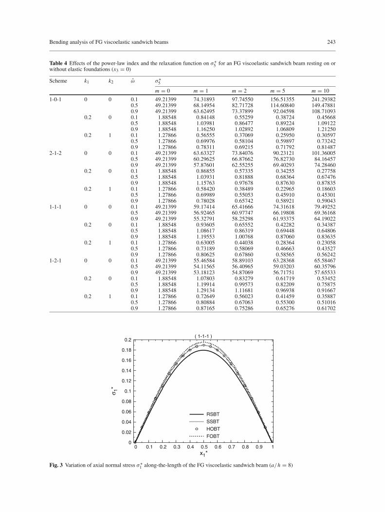
Table 4 Effects of the power-law index and the relaxation function on σ ∗5 for an FG viscoelastic sandwich beam resting on or
without elastic foundations (x3 = 0)
Scheme k1 k2 ω σ ∗5
m = 0 m = 1 m = 2 m = 5 m = 10
1-0-1 0 0 0.1 49.21399 74.31893 97.74550 156.51355 241.293820.5 49.21399 68.14954 82.71728 114.60840 149.478810.9 49.21399 63.62495 73.37899 92.04598 108.71093
0.2 0 0.1 1.88548 0.84148 0.55259 0.38724 0.456680.5 1.88548 1.03981 0.86477 0.89224 1.091220.9 1.88548 1.16250 1.02892 1.06809 1.21250
0.2 1 0.1 1.27866 0.56555 0.37069 0.25950 0.305970.5 1.27866 0.69976 0.58104 0.59897 0.732420.9 1.27866 0.78311 0.69215 0.71792 0.81487
2-1-2 0 0 0.1 49.21399 63.63327 73.84076 90.23121 101.360050.5 49.21399 60.29625 66.87662 76.82730 84.164570.9 49.21399 57.87601 62.55255 69.40293 74.28460
0.2 0 0.1 1.88548 0.86855 0.57335 0.34255 0.277580.5 1.88548 1.03931 0.81888 0.68364 0.674760.9 1.88548 1.15763 0.97678 0.87630 0.87835
0.2 1 0.1 1.27866 0.58420 0.38489 0.22965 0.186030.5 1.27866 0.69989 0.55053 0.45910 0.453010.9 1.27866 0.78028 0.65742 0.58921 0.59043
1-1-1 0 0 0.1 49.21399 59.17414 65.41666 74.31618 79.492520.5 49.21399 56.92465 60.97747 66.19808 69.361680.9 49.21399 55.32791 58.25298 61.93375 64.19022
0.2 0 0.1 1.88548 0.93605 0.65552 0.42282 0.343870.5 1.88548 1.08617 0.86319 0.69448 0.648060.9 1.88548 1.19553 1.00768 0.87060 0.83635
0.2 1 0.1 1.27866 0.63005 0.44038 0.28364 0.230580.5 1.27866 0.73189 0.58069 0.46663 0.435270.9 1.27866 0.80625 0.67860 0.58565 0.56242
1-2-1 0 0 0.1 49.21399 55.46584 58.89103 63.28368 65.584670.5 49.21399 54.11565 56.40965 59.03203 60.357960.9 49.21399 53.18123 54.87069 56.71751 57.65533
0.2 0 0.1 1.88548 1.07803 0.83279 0.61719 0.534520.5 1.88548 1.19914 0.99573 0.82209 0.758750.9 1.88548 1.29134 1.11681 0.96938 0.91667
0.2 1 0.1 1.27866 0.72649 0.56023 0.41459 0.358870.5 1.27866 0.80884 0.67063 0.55300 0.510160.9 1.27866 0.87165 0.75286 0.65276 0.61702
0
0.02
0.04
0.06
0.08
0.1
0.12
0.14
0.16
0.18
0.2
0 0.1 0.2 0.3 0.4 0.5 0.6 0.7 0.8 0.9 1
σ 1*
x1*
( 1-1-1 )
RSBT
SSBT
HOBT
FOBT
Fig. 3 Variation of axial normal stress σ ∗1 along-the-length of the FG viscoelastic sandwich beam (a/h = 8)

244 A. M. Zenkour et al.
-0.55
-0.45
-0.35
-0.25
-0.15
-0.05
0.05
0.15
0.25
0.35
0.45
0.55
0 0.1 0.2 0.3 0.4 0.5 0.6 0.7 0.8 0.9 1
σ 5*
x1*
( 1-1-1 )
RSBT
SSBT
HOBT
FOBT
Fig. 4 Variation of transverse shear stress σ ∗5 along-the-length of the FG viscoelastic sandwich beam (a/h = 8)
0
1
2
3
4
5
6
7
8
9
10
11
0 0.1 0.2 0.3 0.4 0.5 0.6 0.7 0.8 0.9 1
w*
x1*
( 1-1-1 )
RSBT
SSBT
HOBT
FOBT
Fig. 5 Variation of the central deflectionw∗ along-the-length of the FG viscoelastic sandwich beam (a/h = 15, k1 = k2 = 0.01)
7 Numerical results and discussions
In this paper, several examples are performed concerning bending response of FG viscoelastic sandwich beamswith rectangular cross section resting on elastic foundations. The results are evaluated for loading case involv-ing sinusoidal load on the top face whereas the bottom face is resting on two-parameter elastic foundationsand hence the effect on stress distribution and deflection is investigated thoroughly. Based on the analysis ofthe previous sections, the stresses and transverse displacements of simply supported beams are obtained by therefined sinusoidal shear deformation beam theory and compared with those obtained by the simple sinusoidal,higher-order and first-order shear theories.
Nondimensionalized central deflection and stresses given here are presented according to the followingdefinitions:
w∗ = Ee
100hq0w0(x1), σ ∗
1 = 1
q0σ1(x1, x3), σ ∗
5 = 10
q0σ5(x1, x3),
ξ = K
Ee, k1 = K1h
K, k2 = K2
K h, x∗
1 = x1
a, x∗
3 = x3
h.

Bending analysis of FG viscoelastic sandwich beams 245
0
0.5
1
1.5
2
2.5
3
3.5
4
4.5
5(a) (c)
(d)(b)
4 6 8 10 12 14 16 18 20
w*
a / h
( 1-0-1 )
viscoelastic
m = 5
m = 2
m = 1
elastic
0
0.5
1
1.5
2
2.5
3
3.5
4
4.5
5
4 6 8 10 12 14 16 18 20
w*
a / h
( 2-1-2 )
viscoelastic
m = 5
m = 2
m = 1
elastic
0
0.5
1
1.5
2
2.5
3
3.5
4
4.5
5
4 6 8 10 12 14 16 18 20
w*
a / h
( 1-1-1 )
viscoelastic
m = 5
m = 2
m = 1
elastic
0
0.5
1
1.5
2
2.5
3
3.5
4
4.5
5
4 6 8 10 12 14 16 18 20
w*
a / h
( 1-2-1 )
viscoelastic
m = 5
m = 2
m = 1
elastic
Fig. 6 The maximum central deflection w∗ versus a/h for various values of the power-law index m and different types of visco-elastic sandwich beams (k1 = k2 = 0.02). a The (1-0-1) FGM sandwich beam, b the (2-1-2) FGM sandwich beam, c the (1-1-1)FGM sandwich beam, d the (1-2-1) FGM sandwich beam
Numerical results are tabulated in Tables 1–4 and are plotted in Figs. 3–14. Plots of the volume fractionfunction through the thickness of the FG viscoelastic sandwich beam are given in Fig. 2 for different values ofthe power-law index m. The longitudinal stress σ ∗
1 is computed at x1 = a/2, x3 = h/2 and the transverse shearstress σ ∗
5 is computed at x1 = 0, x3 = 3h/10 while the transverse deflection w∗ is computed at x1 = a/2.The value of Poisson’s ratio of the elastic material is taken to be νe = 0.25. It is assumed (unless otherwisestated) for the FG sandwich beam that
ξ = 0.1, m = 1, ω = 0.3, c1 = 0.1, c2 = 0.9, a/h = 10, k1 = 0.2, k2 = 2.
Note that, for the time-dependence solution, the stresses and the deflection may be given in terms of the timeparameter in the following forms:
σ ∗1 = 0.05884073 + 0.16010276 e−τ + 0.00004406 e−0.1τ + 0.04895176 e−0.7τ + 0.09640154 e−0.4τ ,
σ ∗5 = 0.17163142 + 0.09687815 e−τ + 0.00000534 e−0.1τ − 0.00696426 e−0.7τ + 0.01198476 e−0.4τ ,
w∗ = 13.91219899 − 0.57564870 e−τ − 0.00043891 e−0.1τ − 0.87743037 e−0.7τ − 0.70937452 e−0.4τ .
For the sake of completeness and comparison, the influence of the higher-order stress resultants P and Ron the numerical results of FG viscoelastic sandwich beam (1-2-1) resting on elastic foundations is explainedin Table 1. It is to be noticed that the results obtained by the higher-order shear deformation beam theories arelower than those obtained by the first-order one, indicating the influence of the higher-order stress resultants Pand R. Note that for the FOBT, the stress couple M and the stress couple associated with the transverse sheareffect P are equal. In addition, the transverse stress resultants Q and R are also equal.

246 A. M. Zenkour et al.
0.02
0.07
0.12
0.17
0.22
0.27
0.32
0.37
0.42
0.47
0.52 (a) (c)
(d) (b)
4 6 8 10 12 14 16 18 20
σ 1*
a / h
( 1-0-1 )( 1-0-1 )
m = 1m = 2m = 5
0.04
0.1
0.16
0.22
0.28
0.34
0.4
0.46
0.52
0.58
0.64
4 6 8 10 12 14 16 18 20
σ 1*
a / h
( 2-1-2 )
m = 1m = 2m = 5
0.06
0.14
0.22
0.3
0.38
0.46
0.54
0.62
0.7
4 6 8 10 12 14 16 18 20
σ 1*
a / h
( 1-1-1 )
m = 1m = 2m = 5
0.2
0.3
0.4
0.5
0.6
0.7
0.8
0.9
1
4 6 8 10 12 14 16 18 20
σ 1*
a / h
( 1-2-1 )
m = 1m = 2m = 5
Fig. 7 The stress σ ∗1 versus a/h for various values of the power-law index m and different types of viscoelastic sandwich beams
(x3 = h/4). a The (1-0-1) FGM sandwich beam, b the (2-1-2) FGM sandwich beam, c the (1-1-1) FGM sandwich beam, d the(1-2-1) FGM sandwich beam
The stresses σ ∗1 and σ ∗
5 and deflectionw∗ of the mid-plane of FG viscoelastic sandwich beams for differentvalues of the power-law index m and the relaxation function ω and different states of the sandwich beam withvarious types of elastic foundations are listed in Tables 2–4. Since the homogeneous elastic beam is independentof the relaxation function, the results do not change with the variation of ω. Table 2 reveals that, irrespective ofthe elastic foundations, the dimensionless deflectionw∗ of the FG sandwich beams increases with the increaseof m (i.e. with the increase of viscoelastic constituents), whereas its change is reversed with the increase of therelaxation function ω. For the sandwich beams without elastic foundation, regardless of the relaxation functionω, the axial normal stress σ ∗
1 increases to its maximum values and then decreases as m increases, except σ ∗1
for the (1-2-1) sandwich beam, which increases directly (see Table 3). It is also observed from this table that,with the presence of Winkler’s or Pasternak’s elastic foundations, the normal stress σ ∗
1 decreases directly asthe power-law index m increases for the all values of ω, except σ ∗
1 for the (1-2-1) sandwich beam, its changeis reversed because it is estimated at the top interface. It can be seen that the stress σ ∗
1 for the FG foundationbeams is proportional to the relaxation function ω excluding σ ∗
1 for the (1-2-1) FG sandwich beam, while thenormal stress for the foundationless beams decreases as ω increases for m = 1, 2, 5. Table 4 shows that thetransverse shear stress σ ∗
5 increases directly as the power-law index m increases for foundationless sandwichbeams, whereas, for foundation beams, its change is reversed excluding σ ∗
5 for (1-0-1) beams at the all valuesof ω and (2-1-2) beams at ω = 0.9. In general, the results show that the presence of Winkler’s or Pasternak’selastic foundations leads to a significant reduction in the variation of the deflections and stresses.
Figures 3–5 demonstrate the stresses σ ∗1 and σ ∗
5 and central deflection w∗ plots, respectively, using theRSBT, SSBT, HOBT and FOBT. It can be seen that the stress σ ∗
1 and deflection w∗ have their maximumvalues at the center of the beam (x1 = a/2), while σ ∗
5 has its maximums at the tip of the beam. FromFig. 3, significant differences between the results obtained by the refined theory (RSBT) and those obtainedby sinusoidal, higher-order and first-order theories are noted, indicating the effect of transverse normal strainwhich is included in the stress-strain relation of RSBT. It is clear from Figs. 4 and 5 that the disagreement

Bending analysis of FG viscoelastic sandwich beams 247
0
0.2
0.4
0.6
0.8
1
1.2
1.4
1.6
1.8
2 (a) (c)
(d) (b)
4 6 8 10 12 14 16 18 20
σ 5*
a / h
( 1-0-1 )
m = 1m = 2m = 5
0
0.2
0.4
0.6
0.8
1
1.2
1.4
1.6
1.8
2
4 6 8 10 12 14 16 18 20
σ 5*
a / h
( 2-1-2 )
m = 1m = 2m = 5
0
0.2
0.4
0.6
0.8
1
1.2
1.4
1.6
1.8
2
4 6 8 10 12 14 16 18 20
σ 5*
a / h
( 1-1-1 )
m = 1m = 2m = 5
0
0.2
0.4
0.6
0.8
1
1.2
1.4
1.6
1.8
2
2.2
4 6 8 10 12 14 16 18 20
σ 5*
a / h
( 1-2-1 )
m = 1m = 2m = 5
Fig. 8 The stress σ ∗5 versus a/h for various values of the power-law index m and different types of viscoelastic sandwich beams
(x3 = 0). a The (1-0-1) FGM sandwich beam, b the (2-1-2) FGM sandwich beam, c the (1-1-1) FGM sandwich beam, d the(1-2-1) FGM sandwich beam
-0.5
-0.4
-0.3
-0.2
-0.1
0
0.1
0.2
0.3
0.4
0.5
-0.45 -0.35 -0.25 -0.15 -0.05 0.05 0.15 0.25 0.35 0.45
x 3*
σ1*
( 2-1-2 )
∧ ω = 0.1 ∧ ω = 0.2 ∧ ω = 0.5
Fig. 9 Through-the-thickness distributions of axial normal stress σ ∗1 for different values of the relaxation function ω
between RSBT, SSBT and HOBT is much less than the disagreement between any of them and FOBT. Also,it is to be noticed that the sinusoidal shear deformation beam theory suggested by Zenkour [14,17–19,45] isin extremely good agreement with the higher-order shear deformation beam theory.

248 A. M. Zenkour et al.
-0.5
-0.4
-0.3
-0.2
-0.1
0
0.1
0.2
0.3
0.4
0.5
0 0.06 0.12 0.18 0.24 0.3 0.36 0.42 0.48 0.54
x 3*
σ5*
( 2-1-2 )
∧ ω = 0.1 ∧ ω = 0.2 ∧ ω = 0.5
Fig. 10 Through-the-thickness distributions of transverse shear stress σ ∗5 for different values of the relaxation function ω
0
0.4
0.8
1.2
1.6
2
2.4
2.8
3.2
3.6
0 0.1 0.2 0.3 0.4 0.5 0.6 0.7 0.8 0.9 1
w*
x1*
( 2-1-2 )
∧ ω = 0.1 ∧ ω = 0.2 ∧ ω = 0.5
Fig. 11 Along-the-length distributions of the central deflectionw∗ for various values of the relaxation function ω (a/h = 8, k1 =k2 = 0.02)
Figure 6 illustrates the variation of central deflection w∗ as a function of the span-to-thickness ratio a/hfor various values of the power-law index m and different types of viscoelastic sandwich beams. It is to benoted that the deflection w∗ of the homogeneous sandwich beams and FG ones increases gradually as thespan-to-thickness ratio a/h increases. Note that since the stiffness of the elastic materials is higher than thatof the viscoelastic materials, the central deflection of the fully elastic beam (m = 0) is less than that of theviscoelastic sandwich beam, especially for the thick beam. All the FG sandwich beams with intermediateproperties undergo corresponding intermediate values of the deflection.
Figures 7 and 8 exhibit the variations of axial normal stress σ ∗1 and transverse shear stress σ ∗
5 against thespan-to-thickness ratio a/h for various values of the power-law index m and different types of viscoelasticsandwich beams. It is to be seen that the stress σ ∗
1 decreases gradually as the span-to-thickness ratio a/hincreases just as σ ∗
5 . Note that for the (1-2-1) FG sandwich beam, the axial normal stress increases with theincrease of the power-law index m, while for the other types of beams it is monotonically decreasing as thepower-law index increases just as σ ∗
5 for the all types of sandwich beams.Variations of the stresses σ ∗
1 and σ ∗5 through the thickness of the FG sandwich beam are shown graphically
in Figs. 9 and 10. The results for the relaxation function ω = 0.1, 0.2, 0.5 are presented here. The maximum

Bending analysis of FG viscoelastic sandwich beams 249
0
0.04
0.08
0.12
0.16
0.2
0.24
0.28
0.32
0.36
0 1 2 3 4 5 6 7 8 9 10
σ 1*
τ
( 1-1-1 )
k1 = 0.2, k2 = 2.0
k1 = 0.5, k2 = 2.0
k1 = 0.2, k2 = 10
Fig. 12 Dimensionless stress σ ∗1 as a function of the time parameter τ for different values of the elastic foundation parameters
k1 and k2
0.05
0.075
0.1
0.125
0.15
0.175
0.2
0.225
0.25
0.275
0 1 2 3 4 5 6 7 8 9 10
σ 5*
τ
( 1-1-1 )
k1 = 0.2, k2 = 2.0
k1 = 0.5, k2 = 2.0
k1 = 0.2, k2 = 10
Fig. 13 Dimensionless stress σ ∗5 as a function of the time parameter τ for different values of the elastic foundation parameters
k1 and k2
compressive {tensile} stress σ ∗1 occurs in the top {bottom} layer of the beam as shown in Fig. 9. Note that
the plots read negative sign for tensile stresses and positive sign for compressive stresses. Figure 10 shows thesensitivity of the transverse shear stress σ ∗
5 through the thickness of the sandwich beams. It is to be seen fromFigs. 9 and 10 that the stresses are proportional to the relaxation function ω.
Variations of the central deflection w∗ along the length of FG sandwich beams for different values of therelaxation function ω are shown graphically in Fig. 11. It is noticed that the deflection decreases as ω increases.
The plots of the axial stress σ ∗1 , transverse shear stress σ ∗
5 and central deflection w∗ as functions ofthe time parameter τ for different values of the elastic foundation parameters k1 and k2 are presented inFigs. 12–14. As expected the results decrease as the elastic foundation stiffnesses increase. The longitudinalstress σ ∗
1 and transverse shear stress σ ∗5 decrease directly to reach its constant values with the increase of
the time parameter τ . Figure 14 shows that, for k1 = 0.002 and k2 = 0.02, the time parameter τ effectis more pronounced on the deflection of the beam, and it is less pronounced on w∗ for k1 = 0.002 andk2 = 0.1. But for k1 = 0.005 and k2 = 0.02, the deflection takes intermediate values between the two abovestates.

250 A. M. Zenkour et al.
5.8
6.6
7.4
8.2
9
9.8
10.6
11.4
12.2
13
13.8
0 1 2 3 4 5 6 7 8 9 10
w*
τ
( 1-1-1 )
k1 = 0.002, k2 = 0.02
k1 = 0.005, k2 = 0.02
k1 = 0.002, k2 = 0.10
Fig. 14 Dimensionless deflectionw∗ as a function of the time parameter τ for different values of the elastic foundation parametersk1 and k2
8 Conclusions
Refined sinusoidal shear deformation beam theory is effectively used to extensively study the stresses andcentral deflection of the bending of FG viscoelastic sandwich beams resting on two-parameter (Pasternak’s)elastic foundations. The effects of transverse normal strain as well as the shear deformation are included inthe present theory. In order to show that effect, the three shear deformation theories SSBT, HOBT and FOBTare used in our study. Each face of the present sandwich beam is considered to be made of an FG viscoelasticmaterial while the core is considered to be made of an elastic material. The variation of properties throughthe thickness of the faces follows a power-law type. The deflection for the given boundary conditions is highfor a viscoelastic rich beam when compared to an elastic rich beam and it increases as the power-law indexincreases. Investigations on the effects of the relaxation function, span-to-thickness ratio, elastic foundationparameters and the time parameter on the FG viscoelastic sandwich beams with elastic cores are presented.
Appendix A
Denoting the transforms of �(t) and gχi (t) by �∗(t) and g∗χi(t), respectively, where i = 1, 2 and χ1 =
1/2, χ2 = 2, we may deduce the Laplace–Carson transform of them as follows:
�∗(s) = 1
ω∗(s)= 1
c1 + c2s/(s + 1/ts), (47)
or
�∗(s) = 1
c1
(
1 − c3s
s + c4
)
, (48)
where
c3 = c2
c1 + c2, c4 = c1
(c1 + c2)ts. (49)
Then we can find the function �(t) by using the inverse Laplace–Carson transform of Eq. (48) in the form
�(t) = 1
c1
[
1 − c2
c1 + c2e− c1τ(c1+c2)
]
, τ = t
ts. (50)

Bending analysis of FG viscoelastic sandwich beams 251
Similarly
g∗χi(s) = 1
1 + χiω∗(s)= 1
1 + χi {c1 + c2 [s/(s + 1/ts)]} , (51)
or
g∗χi(s) = 1
1 + c1χi
(
1 − c5s
s + c6
)
, (52)
where
c5 = c2χi
1 + (c1 + c2)χi, c6 = 1 + c1χi
[1 + (c1 + c2)χi ]ts . (53)
Using the Laplace–Carson transform of Eq. (52), one obtains
gχi (t) = 1
1 + c1χi
[1 − c5e−c6t] , (54)
or
gχi (t) = 1
1 + c1χi
[
1 − c2χi
1 + (c1 + c2)χie−(1+c1χi )τ/[1+(c1+c2)χi ]
]
. (55)
References
1. Shi, Y., Sol, H., Hua, H.: Material parameter identification of sandwich beams by an inverse method. J. Sound Vib. 290, 1234–1255 (2006)
2. Yim, J.H., Cho, S.Y., Seo, Y.J., Jang, B.Z.: A study on material damping of 0◦ laminated composite sandwich cantileverbeams with a viscoelastic layer. Compos. Struct. 60, 367–374 (2003)
3. Barbosa, F.S., Farage, M.C.R.: A finite element model for sandwich viscoelastic beams: Experimental and numerical assess-ment. J. Sound Vib. 317, 91–111 (2008)
4. Bekuit, J.-J.R.B., Oguamanam, D.C.D., Damisa, O.: A quasi-2D finite element formulation for the analysis of sandwichbeams. Fin. Elem. Anal. Des. 43, 1099–1107 (2007)
5. Nayfeh, S.A.: Damping of flexural vibration in the plane of lamination of elastic-viscoelastic sandwich beams. J. SoundVib. 276, 689–711 (2004)
6. Lin, C.Y., Chen, L.W.: Dynamic stability of rotating composite beams with a viscoelastic core. Compos. Struct. 58, 185–194 (2002)
7. Yan, W., Chen, W.Q., Wang, B.S.: On time-dependent behavior of cross-ply laminated strips with viscoelastic inter-faces. Appl. Math. Model. 31, 381–391 (2007)
8. Barkanov, E., Rikards, R., Holste, C., Täger, O.: Transient response of sandwich viscoelastic beams, plates, and shells underimpulse loading. Mech. Compos. Mater. 36, 215–222 (2000)
9. Galucio, A.C., Deü, J.-F., Ohayon, R.: Finite element formulation of viscoelastic sandwich beams using fractional derivativeoperators. Comput. Mech. 33, 282–291 (2004)
10. Yen, J.Y., Chen, L.W., Wang, C.C.: Dynamic stability of a sandwich beam with a constrained layer and electrorheologicalfluid core. Compos. Struct. 84, 209–219 (2008)
11. Yan, W., Ying, J., Chen, W.Q.: Response of laminated adaptive composite beams with viscoelastic interfaces. Compos.Struct. 74, 70–79 (2006)
12. Teng, T.L., Hu, N.K.: Analysis of damping characteristics for viscoelastic laminated beams. Comput. Methods Appl. Mech.Engrg. 190, 3881–3892 (2001)
13. Beldica, C.E., Hilton, H.H.: Nonlinear viscoelastic beam bending with piezoelectric control—analytical and computationalsimulations. Compos. Struct. 51, 195–203 (2001)
14. Zenkour, A.M.: Benchmark trigonometric and 3-D elasticity solutions for an exponentiolly graded thick rectangularplate. Arch. Appl. Mech. 77, 197–214 (2007)
15. Zenkour, A.M., Elsibai, K.A., Mashat, D.S.: Elastic and viscoelastic solutions to rotating functionally graded hollow andsolid cylinders. Appl. Math. Mich. Engl. Ed. 29(12), 1601–1616 (2008)
16. Sankar, B.V.: An elasticity solution for functionally graded beams. Compos. Sci. Tech. 61, 689–696 (2001)17. Zenkour, A.M.: A comprehensive analysis of functionally graded sandwich plates: Part 1-deflection and stresses. Int. J.
Solids Struct. 42, 5224–5242 (2005)18. Zenkour, A.M.: A comprehensive analysis of functionally graded sandwich plates: Part 2-Buckling and free vibration. Int.
J. Solids Struct. 42, 5243–5258 (2005)19. Zenkour, A.M.: Generalized shear deformation theory for bending analysis of functionally graded plates. Appl. Math.
Model. 30, 67–84 (2006)20. Zenkour, A.M., Alghamdi, N.A.: Thermoelastic bending analysis of functionally graded sandwich plates. J. Mater.
Sci. 43, 2574–2589 (2008)

252 A. M. Zenkour et al.
21. Kadoli, R., Akhtar, K., Ganesan, N.: Static analysis of functionally graded beams using higher order shear deformationtheory. Appl. Math. Modell. 32, 2509–2525 (2008)
22. Reddy, J.N.: Analysis of functionally graded plates. Int. J. Numer. Meth. Eng. 47, 663–684 (2000)23. Reddy, J.N., Chin, C.D.: Thermomechanical analysis of functionally graded cylinders and plates. J. Thermal Stresses 21, 593–
626 (1998)24. Reddy, J.N., Cheng, Z.Q.: Three-dimensional thermomechanical deformations of functionally graded rectangular plates. Eur.
J. Mech. A Solids 20, 841–855 (2001)25. Arciniega, R.A., Reddy, J.N.: Large deformation analysis of functionally graded shells. Int. J. Solids Struct. 44, 2036–
2052 (2007)26. Praveen, G.N., Reddy, J.N.: Nonlinear transient thermoelastic analysis of functionally graded ceramic–metal plates. Int. J.
Solids Struct. 35, 4457–4476 (1998)27. Chakraborty, A., Gopalakrishnan, S., Reddy, J.N.: A new beam finite element for the analysis of functionally graded mate-
rials. Int. J. Mech. Sci. 45, 519–539 (2003)28. Jin, Z.H., Paulino, G.H.: A viscoelastic functionally graded strip containing a crack subjected to in-plane loading. Eng. Fract.
Mech. 69, 1769–1790 (2002)29. Ghosh, M.K., Kanoria, M.: Analysis of thermoelastic response in a functionally graded spherically isotropic hollow sphere
based on GreenuLindsay theory. Acta Mech. 207, 51–67 (2009)30. Ueda, S.: A cracked functionally graded piezoelectric material strip under transient thermal loading. Acta Mech. 199,
53–70 (2008)31. Li, X.Y., Ding, H.J., Chen, W.Q.: Axisymmetric elasticity solutions for a uniformly loaded annular plate of transversely
isotropic functionally graded materials. Acta Mech. 196, 139–159 (2008)32. Etemadi, E., Khatibi, A.A., Takaffoli, M.: 3D finite element simulation of sandwich panels with a functionally graded core
subjected to low velocity impact. Compos. Struct (2009) (in press)33. Anderson, T.A.: A 3-D elasticity solution for a sandwich composite with functionally graded core subjected to transverse
loading by a rigid sphere. Compos. Struct. 60, 265–274 (2003)34. Ávila, A.F.: Failure mode investigation of sandwich beams with functionally graded core. Compos. Struct. 81, 323–330 (2007)35. Bhangale, R.K., Ganesan, N.: Thermoelastic buckling and vibration behaior of functionally graded sandwich beam with
constrained viscoelastic core. J. Sound Vib. 295, 294–316 (2006)36. Pradhan, S.C., Murmu, T.: Thermo-mechanical vibration of FGM sandwich beam under variable elastic foundations using
differential quadrature method. J. Sound Vib. 321, 342–362 (2009)37. Ying, J., Lü, C.F., Chen, W.Q.: Two-dimensional elasticity solutions for functionally graded beams resting on elastic foun-
dations. Compos. Struct. 84, 209–219 (2008)38. Aköz, A.Y., Kadioglu, F.: The mixed finite element solution of circular beam on elastic foundation. Comput.
Struct. 60(4), 643–651 (1996)39. Chen, W.Q., Lü, C.F., Bian, Z.G.: A mixed method for bending and free vibration of beams resting on a Pasternak elastic
foundation. Appl. Math. Model. 28, 877–890 (2004)40. Matsunaga, H.: Vibration and buckling of deep beam-columns on two-parameter elastic foundations. J. Sound Vib. 228, 359–
376 (1999)41. Sato, M., Kanie, S., Mikami, T.: Mathematical analogy of a beam on elastic supports as a beam on elastic foundation. Appl.
Math. Model. 32, 688–699 (2008)42. Tsiatas, G.C.: Nonlinear analysis of non-uniform beams on nonlinear elastic foundation. Acta Mech. (2009) (in press)43. Illyushin, A.A., Pobedrya, B.E.: Foundation of mathematical theory of thermo viscoelasticity. Moscow: Nauka (1970) (in
Russian)44. Allam, M.N.M., Pobedrya, B.E.: On the solution of quasi-static problem in anisotropic viscoelasticity. ISV Acad Nauk Ar
SSR, Mech. 31, 19–27 (1978) (in Russian)45. Zenkour, A.M.: Buckling of fiber-reinforced viscoelastic composite plates using various plate theories. J. Eng. Math. 50,
75–93 (2004)