m103 99r dc2 operation - e.d. etnyre centennial operation maintenance and safety manual ... heating...
TRANSCRIPT

1
Black-TopperBlack-TopperBlack-TopperBlack-TopperBlack-TopperCentennialCentennialCentennialCentennialCentennial
Operation Maintenance and Safety Manualfor Units with DC2 Controls
E. D. ETNYRE & Co., Oregon, Illinois 61061-9778
M-103-00Supercedes M-103-99R
1333 South Daysville Road Phone: 815-732-2116Fax: 815-732-7400 www.etnyre.com
© Copyright 2000 E. D. ETNYRE & CO. All rights reserved. No part of this publication may be reproduced by any means,electronic or mechanical, without the express permission of E. D. ETNYRE & CO. The enclosed drawings remain the property of
E. D. ETNYRE & CO. and no part may be copied or used without the express permission of E. D. ETNYRE & CO.

2
M-103-00(Supercedes M-103-99R)
Black-Topper Centennial Operation Maintenance and Safety Manual
WARRANTYE. D. Etnyre & Co. warrants to the original Purchaser, it’s new product to be free from defects in material and workmanship for a period of twelve(12) months after date of delivery to original Purchaser. The obligation of the Company is limited to repairing or replacing any defective partreturned to the Company and will not be responsible for consequential damages or any further loss by reason of such defect.
The company excludes all implied warranties of merchantability and fitness for a particular purpose. There are no warranties, express or implied,which extend beyond the description of the goods contained in this contract.
This warranty does not obligate the Company to bear the cost of machine transportation in connection with the replacement or repair of defectiveparts, nor does it guarantee repair or replacement of any parts on which unauthorized repairs or alterations have been made or for components notmanufactured by the Company except to the extent of the warranty given by the original Manufacturer.
This warranty does not apply to:
(1) Normal startup services, normal maintenance services or adjustments usually performed by the selling dealer, factory service representativeor customer personnel.
(2) Any product manufactured by E. D. Etnyre & Co. purchased or subjected to rental use.
(3) Any product or part thereof which shows improper operation, improper maintenance, abuse, neglect, damage or modification after shipmentfrom factory.
(4) Any product or part thereof damaged or lost in shipment. Inspection for damage should be made before acceptance or signing any deliverydocuments releasing responsibility of the delivering carrier.
This warranty and foregoing obligations are in lieu of all other obligations and liabilities including negligence and all warranties of merchant-ability or otherwise, express or implied in fact or by law.
WARNING
Fluoroelastomer HandlingSome O-rings and seals used in this vehicleare made from fluoroelastomers, When usedunder design conditions, fluoroelastomers donot require special handling. However, whenfluoroelastomers are heated to temperaturesbeyond their design temperature (around600º Fahrenheit), decomposition may occurwith the formation of hydrofluoric acid.Hydrofluoric acid can be extremely corrosiveto human tissue if not handled properly.
A degraded seal may appear as a charred orblack sticky mass, Do not touch either theseal or the surrounding equipment withoutwearing neoprene or PVC gloves ifdegradation is suspected. Wash parts andequipment with 10% lime water (calciumhydroxide solution) to neutralize anyhydrofluoric acid.
If contact with the skin occurs, wash theaffected areas immediately with water. Thenrub a 2.5 calcium gluconate gel into the skinuntil there is no further irritation, whileseeking prompt medical attention.
Note to Physicians: For advice or treatmentof HF burns, call the DuPont MedicalEmergency number, 1-800-441-3637
WARNING
Do not use this machine for any operationwhich is not described in this manual.If you have any questions about operationof this machine, contact the Etnyre ServiceDepartment at1-800-995-2116 or 1-815-732-2116.Operations that are not approved couldcause serious injury or death.
Please note this warning and remember -Always start and operate the engine in awell ventilated area;
If in an enclosed area, vent the exhaust tothe outside;
Do not modify or tamper with the exhaustsystem.
CALIFORNIAProposition 65 WARNING
Diesel engine exhaust and some of its con-stituents are known to the State of Californiato cause cancer, birth defects, and otherreproductive harm.

3
TABLE OF CONTENTS
Figure 1 Etnyre Computator ............................................ 16Figure 2 Using the Measuring Stick ................................ 20Figure 3. Valve Positions for Filling Through Fill Line ...... 21Figure 4. Valve Positions for Filling Through Manhole ..... 22Figure 5 Valve Positions for Circulating in the Tank ......... 23Figure 6. Valve Positions for Circulating in the Bar .......... 24Figure 7. Adjusting the Spray Bar Nozzles ...................... 26Figure 8. Adjusting the Spray Bar Height. ....................... 26Figure 9. Valve Positions - Spraying Through Spray Bar. 27Figure 10. Valve Positions for Suck Back of Spray Bar. ... 28Figure 11. Valve Positions for Handspray. ....................... 29Figure 12 Valve Positions for Handspray Suckback ........ 30Figure 13. Valve Positions for Pump Off .......................... 31Figure 14. Valve Positions for Transfer ............................ 32Figure 15. Valve Positions for Flushing ............................ 33Figure 16. Manual Control Burner System ...................... 35Figure 17. Outfire Controlled Burner System .................. 37Figure 18 Burner with Auto Ignition&Temp Cont ............. 38Figure 19. Electric Burner System .................................. 39Figure 20. Burner Electrode Adjustments ....................... 43Figure 21. Electrode Assembly Installation ..................... 43Figure 21a. Nozzle Adjustment ....................................... 43Figure 23 Nozzle Height Adjustment ............................... 44Figure 22. Nozzle Angle Adjustment ............................... 44Figure 24 Etnyre Asphalt Pump ..................................... 45Figure 25 Fluid Cleanliness Chart ................................... 48Figure 26 Serial Number Plate Location ......................... 52
Warranty ............................................................................ 2Introduction ............................................................. 8
General Safety InstructionsWarning And Instruction Plates ......................................... 4General Safety Instructions ............................................... 5Safety Precautions, Hazard Seriousness Level ................ 5Reporting Safety Defects .................................................. 8Fluoroelastomer Handling ................................................. 2
Component Location And IdentificationComponent Location And Identification ............................ 9Hydraulic Tank and Components .................................... 10Spray Bar Component Identification ............................... 10Cab Control panel ........................................................... 11Rear Control panel .......................................................... 14
Preparing for OperationPreparing for Operation ................................................... 16General Operation ........................................................... 19Set up of the DC-2 Computer .......................................... 16Using the Etnyre Computator (See Fig. 1) ...................... 16Engaging Pump on PTO Equipped Distributors .............. 18Foaming .......................................................................... 18Mixing Dow-Corning DC-200 Anti Foam Agent ............... 19Tank Capacity .................................................................. 19Filling Through the Fill Line ............................................. 19Connections and Preliminary Checks ............................. 19Filling from the Cab ......................................................... 20Filling from the Rear Control Panel ................................. 21Filling through the Manhole ............................................. 22Circulating Product in the Tank........................................ 23Circulating in the tank from the cab................................. 23Circulating in the Tank from the Rear Control Panel ....... 24Circulating Product in the Bar ......................................... 25Spraying Operations ....................................................... 25Adjusting the Spray Bar Nozzle Angle ............................ 26Adjusting the Spray Bar Height ....................................... 26Spraying through the Bar ................................................ 26Setting the Digital Memory Presets ................................. 27Suckback from the Cab ................................................... 28Handspraying .................................................................. 29Suck Back for Hand Spray Operations ............................ 30Pump Off Operations ...................................................... 31Transfer Operations ......................................................... 32Flushing Operations ........................................................ 33
HeatingHeating with Liquid Propane Gas (LPG) Burners ........... 34LPG Supply Tank Requirements ..................................... 34Manual Control Burners .................................................. 34Burner Operation ............................................................ 34Burners With Outfire Controls ......................................... 36Burner Operation with Outfire Controls ........................... 36Burners with Auto Ignition and Temp Limiting Control ..... 38Burner Operation with Auto Ignition & Temp Control ....... 38Electric Driven Burner Operation .................................... 39
Troubleshooting .................................................. 41
MaintenanceElectrode Assembly Adjustments .................................... 43Burner Air Band Settings ................................................ 43Check Ignition Transformer Spark ................................... 43Fire Burners .................................................................... 44Adjusting Spray Bar Nozzle Angle .................................. 44Adjusting Spray Bar Height ............................................. 44Servicing The Etnyre P-15 Pump .................................... 45
Vacuum Check ......................................................... 45Pump Disassembly And Inspection ......................... 45Impeller Installation And Pump Assembly ................ 45
General Fuel DataAnd Heating Terminology ................................................ 4646DRHydraulic Fluid Requirements
General Information ................................................. 47Hydraulic fluid requirements .................................... 47Viscosity & Temperature Requirements ................... 47Contamination Levels .............................................. 48
Lubrication Chart ................................................ 50
Etnyre Spraybar Nozzles .................................... 51
Decimal Equivalvent Chart ................................... 1
List of Illustrations
4 Specify Unit Serial No., Part No., & Part Description
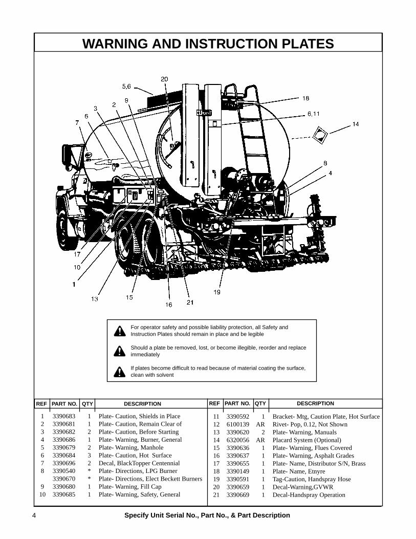
WARNING AND INSTRUCTION PLATES
REF PART NO. QTY DESCRIPTION REF PART NO. QTY DESCRIPTION
For operator safety and possible liability protection, all Safety andInstruction Plates should remain in place and be legible
Should a plate be removed, lost, or become illegible, reorder and replaceimmediately
If plates become difficult to read because of material coating the surface,clean with solvent
1 3390683 1 Plate- Caution, Shields in Place 2 3390681 1 Plate- Caution, Remain Clear of 3 3390682 2 Plate- Caution, Before Starting 4 3390686 1 Plate- Warning, Burner, General 5 3390679 2 Plate- Warning, Manhole 6 3390684 3 Plate- Caution, Hot Surface 7 3390696 2 Decal, BlackTopper Centennial 8 3390540 * Plate- Directions, LPG Burner
3390670 * Plate- Directions, Elect Beckett Burners 9 3390680 1 Plate- Warning, Fill Cap10 3390685 1 Plate- Warning, Safety, General
11 3390592 1 Bracket- Mtg, Caution Plate, Hot Surface12 6100139 AR Rivet- Pop, 0.12, Not Shown13 3390620 2 Plate- Warning, Manuals14 6320056 AR Placard System (Optional)15 3390636 1 Plate- Warning, Flues Covered16 3390637 1 Plate- Warning, Asphalt Grades17 3390655 1 Plate- Name, Distributor S/N, Brass18 3390149 1 Plate- Name, Etnyre19 3390591 1 Tag-Caution, Handspray Hose20 3390659 1 Decal-Warning,GVWR21 3390669 1 Decal-Handspray Operation

5
GENERAL SAFETY INSTRUCTIONSThe operation of a Bituminous Distributor normally requires handling of liquid products at elevated tempera-
ture. Also, these liquids may be of a volatile nature. A heating system is supplied to raise or maintain the producttemperature, and these systems use highly combustible fuels. As with any type of construction equipment, there arecertain hazards associated with careless or improper operation.
Safety warnings have been provided to call attention to any potentially hazardous situation that may causeproperty damage, personal injury or death to the operator or bystanders. These safety warnings will be shown atvarious times throughout this manual, as they are applicable to the subject being presented. These safety warnings areidentified by the following warning symbols:
Safety Precautions, Hazard Seriousness LevelYou will find safety information boxes throughout this manual. These boxes contain information alerting you to
situations or actions to avoid.
Signal words (DANGER, WARNING and CAUTION) are used to identify levels of hazard seriousness. Theirselection is based on the likely consequence of human interaction with a hazard. Definitions of hazard levels are asfollows.
DANGER - Immediate hazards which will result in severe personal injury or death.
WARNING - Hazards or unsafe practices which could result in severe personal injury ordeath.
CAUTION - Hazards or unsafe practices which could result in minor personal injury or prod-uct or property damage.
All of these warnings are listed below and they also appear throughout the manual. In addition to these, you willfind notes throughout the manual.
NOTE - A note provides general information that the operator should be aware of when performingan operation.
DANGER
To avoid an extreme fire hazard or explosion,NEVER use gasoline as fuel in low pressure orgenerating burners.
WARNING
A fully charged dry chemical type fireextinguisher must be within easy reachwhenever the burners are operating or there isan open flame near the distributor. Theminimum capacity of the fire extinguishershould be 10 pounds.

6
WARNING
To prevent an explosion or fire hazard: Positionthe unit broadside to the wind to preventvolatile fumes from drifting toward the burners.
To prevent an explosion or fire hazard: Do notoperate the burners if the tank is damaged orleaking
To prevent an explosion or fire hazard: Ensurethat the burners are extinguished beforeremoving any material from the tank in anymanner. Liquid petroleum (LP) burners cansupport a flame for several minutes after thefuel supply is turned off.
To prevent an explosion: Do not operate theburners when the vehicle is unattended, whenthe vehicle is in motion, or with the vehicle in aconfined area.
To prevent an explosion or fire hazard: Whenthe burners go out, shut off the fuel supply toboth burners and allow the flues to ventilate forat least 3 minutes before re-lighting theburners.
To prevent an explosion or fire hazard: Do notheat the material beyond the manufacturer’srecommended temperature.
To prevent an explosion or fire hazard: Keepburning cigarettes or other sources ofcombustion away from manholes and overflowvents.
To prevent possible hand or facial burns:Always light the inside burner first. Do notreach across a lit burner to light or re-light theinside burner. Shut off the outside burnerbefore lighting the inside burner.
To prevent possible burns: Always use a torchto light the burners. Never attempt to light theburners using a match or pocket lighter.
WARNING
To prevent an explosion or fire hazard: Checkthe tank vent to insure that it is free fromobstruction before lighting the burners.
To prevent an explosion or fire hazard: Do notoperate the burners with the manhole open oropen the manhole while the burners are inoperation.
To prevent possible burns to operators orbystanders, or possible equipment damage, donot start any operation if any control settingsare unknown.
To prevent possible burns from leakingmaterial: Be sure all pipe, cap and hoseconnections are secure before opening valves,or beginning any operation.
To prevent possible burns from hot asphaltspray: Do not stand, or allow anyone to stand,where accidental opening of a valve maycause contact with hot asphalt.
To prevent an explosion or fire hazard: Keeparea free of all sources of combustion whenspraying.
To prevent possible burns from foaming orviolent eruption, do not load tank with materialtemperature over 200ºF if water orcondensation is present in tank, or if emulsionwas used in the previous load. Do not heatmaterial over 200ºF if moisture or emulsifiedmaterial is present in tank.
To prevent an explosion or fire hazard:Eliminate sparks from engine exhaust.
To prevent burns from hot asphalt whenhandspraying: Hold the handspray gun inproper position and watch for other people.
To prevent burns: Always wear insulatedgloves when handling spray bar sections orhoses.

7
WARNING
To prevent severe injury from becomingentangled in machinery: Stand clear of rotatingdrives.
To prevent possible injury: Always open themanhole cover slowly. Pressure build up in thetank may cause the cover to burst open.
To prevent possible fire hazards, burns or falls:Keep the unit clean for safe operation.
To prevent possible burns from materialoverflow: Allow sufficient space in the tank forexpansion of the material when heating
Before removing the fill line cap, make certainthat the asphalt pump is turning and thesuction valve is closed.
To prevent possible personal injury: Do notload the vehicle beyond the GAWR or GVWR.The maximum load volume must be calculatedbased on material density
To prevent possible burns: Use extremecaution when using a torch to heat the pump.Asphalt accumulated around the pump mayignite when heating the pump with a torch
Allowing the burners to operate for a longperiod of time without circulating can damagethe product and create explosive fumes. Ifproduct cannot be circulated after fifteenminutes of heating without circulation, theburners should be extinguished for 20 - 30minutes before re-lighting the burners.
To prevent burns: Always wear eye protection,long sleeve shirt, insulated gloves, boots, andlong pants outside the boots when workingaround the distributor.
To prevent an explosion or fire hazard: Flues,must be covered by a minimum 6 inches ofmaterial (bitumen) when burners are inoperation
Use the measuring stick as shown in figure 2 on page21 to determine the amount of product in the tank be-fore lighting burners. The minimum amounts shownon the warning placard only apply if the tank is level.Remember that the measuring stick is accurate onlywhen the tank is level. If the tank is not level, reposi-tion the distributor to place the tank in a level positionbefore taking final measurement. You must have at leastthe amounts shown, with the tank level, in order to safelylight the lower burner and upper burner respectively.Failure to have the appropriate amount, accuratelymeasured can result in an explosion causing deathor serious injury.

8
INTRODUCTION
Your Etnyre Blacktopper Centennial Distributor isdesigned to give you many years of accurate, depend-able, and economic service. The following instructionswill enable you to receive the maximum performancefrom your Blacktopper Centennial Distributor.
The Blacktopper Centennial Distributor’s controlsare designed for simple operation. They require a mini-mum of training for proficient usage. The exclusiveEtnyre circulating system is designed and built for han-dling all grades of bituminous materials efficiently.
This manual is provided as a tool to aid personnel inthe operation of the Etnyre Blacktopper CentennialDistributor in a safe and efficient manner, As with anytype of construction equipment, there are certain haz-ards associated with improper or careless operation. Theability to read and understand the instructions in thismanual should be a required qualification to becomean operator. There are also functions that require a cer-tain amount of physical strength to accomplish. Per-sons lacking the required strength may not only placethemselves in jeopardy, but also others in the vicinity.
This manual covers standard features and optionsfor truck mounted units with DC-2 controllers only. Ifyour unit is equipped with Basic Controls, please referto Operation manual number M-102-99 or later. If yourunit incorporates custom features, some of the infor-mation contained in this manual may not apply. If youhave any questions regarding this manual or your unit,contact your Etnyre dealer or the E. D. Etnyre ServiceDepartment at 1-800-995-2116.
CAUTION
Unusually strong electromagnetic interferencecould cause the electronic controls on thisequipment to temporarily malfunction. Test theeffect of two way radios and similar equipmentwhile operating in a safe area.
Reporting Safety DefectsIf you believe that your vehicle has a defect which
could cause a crash, or could cause injury or death, youshould immediately inform the National Highway Traf-fic Safety Administration (NHTSA) in addition to no-tifying E. D. Etnyre & Co.
If NHTSA receives similar complaints, it may openan investigation; and, if it finds that a safety defect ex-ists in a group of vehicles, it may order a recall andremedy campaign. However, NHTSA cannot becomeinvolved in individual problems between you, yourdealer, or E. D. Etnyre & Co.
To contact NHTSA, you may either call the AutoSafety Hotline toll free at 1-800-424-9393 (or 336-0123in the Washington, D.C. area). or write to NHTSA, U.S.Department of Transportation, Washington, DC, 20696.You can also obtain other information about motor ve-hicle safety from the hotline.

9
COMPONENT LOCATION AND IDENTIFICATION
Right Spray BarFeed Tube
Left Spray BarFeed Tube
Hand Spray Gun
Left Spray Bar Carry Tube
Asphalt PumpDrive Motor
Right Spray BarCarry Tube
Asphalt Pump
4 Way Valve ControlLever
Suction Screen
Optional Front Suction Valve(not shown)
Rear Suction ValveSuck Back Valve Control
Butterfly Valve (underneath)
Strainer/Valve Box
Handspray Suck Back Valve
Transfer Valve
Transfer Line
Transfer LineSuck Back Valve
Butterfly Valve Lever
Fill Line
Fill Line Strainer
Flushing SystemValve
Hand Spray Valve

10
COMPONENT LOCATION AND IDENTIFICATION
Gang On/Off Controls(optional)Air cylinder on spraybar iscontrolled by a switch in thecab control panel. This onecylinder controls on/off of allspray bar valves simulta-neously (gang). Flip levers onvalves allow manual control ofindividual valves.
One Foot Controls (standard)Air cylinders on spraybar are individually controlled byswitches in the cab control panel. Each cylinder controlson/off of 3 spray bar valves (one foot of spray). Flip leverson valves allow manual control of individual valves.
1. Hydraulic Filter2. Thermo Switch3. Hydraulic Oil Specifications
Instruction Plate4. Mounting Bracket5. Hydraulic Tank Assembly6. Breather7. Fill Cap8. Pipe Plug9. Thermometer10.Oil Eye Sight Plug
Right Wing Sectionwith Spray Valves
Left Wing Section
8' Center Sectionwith Valves and Nozzles
Spray BarFeed Tubes
Spray Valve
Flip Lever
BreakawaySwivel Joint
Nozzle
Control Options:Gang On/Off ControlsOne Foot Controls
4
1
15
6
7
8
8
9
2
310
4
Spray Bar Component Identification
Hydraulic Tank and Components

11
R
HYD OIL
PTO LOWTANK LEVEL
FRFRONTONT
REARREAR
SUCTION
3361133G
SHIFT LIFT
WING FOLD
1 2 3 4 5
CHANGECHANGE
DISPLADISPLAY
RESETRESET
GALLONSGALLONSLITRESLITRES
RESETRESET
FEETFEETMETRESMETRES
ON
OFF
ON
OFF
APPLICAAPPLICATIONTIONRARATETE
POWER
CIRCULACIRCULATION TION RARATETE
SPRAYBAR
MEMORMEMORY
MAIN BAR
LEFT WING RIGHT WING
TEMP 4 3 2 1 1 2 3 4
CIRC. IN TANKLOADSUCK BACK
CIRC.IN BAR
MARKER 12 11 10 9 8 7 6 5 5 6 7 8 9 10 11 12 MARKER
HYD MOTORSUCKBACK
BAR
CENTERED
HIGHHIGH
LOLOW
ONON
OFFOFF
ONON
OFFOFF
MIRROR BAR LATCH
1
2
3
4
5
6
7
8 8
9
10
11
12
1313
14
151516 17
18
19
20
21
2223
24
COMPONENT LOCATION AND IDENTIFICATION
CAB CONTROL PANELSEE PAGE 13 FOR DESCRIPTION OF ITEMS

12
COMPONENT LOCATION AND IDENTIFICATION
Cab Control Panel
1. Spray Bar Switch
Turns all activated spray bar valves On or Off.
2. Hydraulic Oil Temperature Warning Light
Indicates that at the hydraulic oil temperature hasexceeded 180ºF. Stop immediately and determine thecause of the high temperature. Failure to do so will re-sult in damage to hydraulic components.
3. PTO Indicator Light
Indicates PTO engagement for units equipped witha PTO driven hydrostatic pump.
4. Low Tank Level Indicator Light
Indicates low material level in the tank when lit.
5. Power Switch
Controls power to both the front and rear control pan-els, either On or Off. Both the front and rear panel powerswitches must be on to operate the distributor.
6. Bar Shift Switch
Moves the entire Spray Bar left or right. It is part ofthe power lift, shift and wing fold option.
7. Bar Lift Switch
This switch raises and lowers the bar to the lowerbar stops and the upper position where it may be latched.It is part of the power lift, shift and wing fold option.
8. Wing Fold Switches
Raise and lower the left and right wings. They arealso part of the power lift, shift and fold option. It ispossible to have three separate folding sections on eachwing. If you only have one folding section on a sideyou will only have one switch per side, and so on.
9. Digital Display Screen
The digital display shows the application rate in gal-lons/sq yd on the upper line of the display. The lowerline shows the speed in fpm on the left side and thepump rate in gpm on the right side. Pushing the changedisplay button once will move you to the next screenwhich shows the feet of bar selected, feet traveled andthe gallons sprayed since the last time the reset gallonsbutton or reset feet button was pushed. Pushing thechange display button again will move you to the next
screen which displays the sq. yd. shot since the last timethe reset buttons were pushed simultaneously. Pushingthe change display button again will move you to thenext screen which displays the material temperature(optional). Pushing the change display button again willmove you to the next screen which displays the startup factor. The start up factor sets how the spray barwill act when it is first turned on. It is adjusted usingthe Application Rate switch. The start up factor is nor-mally set at 100% from the factory. If the start is thin orweak, you can increase the start up factor to compen-sate for this. A higher number will make the beginningof the shot more aggressive or fatter. You may have tochange the start up factor by as much as 25 to 30% tosee the appropriate change. Conversely if the start ofthe shot is too fat and heavy you would have to de-crease the start up factor by as much as 25 to 30% toget it where you want it. You can then make some fineradjustments once you get it close to what you desire.Pushing the change display button again will move youto the next screen which displays the minimum pumpspeed. The minimum pump speed should be set to 0using the application rate switch. When the minimumpump speed has been set, depress the reset gallons but-ton to move to the next screen. The display can also bechanged to show all of the above items in metric unitsif so desired. See the part of the manual on screen setup for a description of how to do this.
10. Circulation Rate Switch
This switch controls the speed of the asphalt pumpfor all functions requiring circulation or transfer ofmaterial except spraying. You should select the spraybar length to be used before setting the circulation rate.When spraying (the spray bar switch is on), the asphaltpump is controlled by the setting of the Application Rateswitch. To increase the circulation rate, hold the Circu-lation Rate switch up, and to decrease the circulationrate, hold the Circulation Rate switch down. Holdingthe switch up or down for more than a 5 seconds, causesthe circulation rate to change faster. The last number toappear on the digital screen immediately after releas-ing the circulation rate switch will be the set point.
11. Reset Feet Button
This button resets the feet traveled count to zero. Itcan be used after each shot if so desired or at the end ofthe day’s work.

13
COMPONENT LOCATION AND IDENTIFICATION
12. Suction Switch
This switch is used to select the use of the optionalfront suction valve instead of the rear suction valve.This switch is only installed on distributors which havethe optional front suction valve installed.
13. Bar Selector Switches
These switches actuate each individual foot of spraybar for control of which parts of the spray bar will openwhen the spray bar switch is turned on. In the up posi-tion, the selected foot of spray bar will come on whenthe spray bar switch is turned on. The computer willautomatically change the pumping rate whenever aswitch is turned on or off while spraying, to compen-sate for the shorter or longer number of feet beingsprayed. These switches are only installed when thedistributor is equipped with the one foot control op-tion, and then only for the number of feet of bar origi-nally installed at the factory.
14. Rotary Actuator
This knob is for the optional cab control of the 4-way valve and the suction valve at the rear of the dis-tributor. This makes it unnecessary to get out of the caband go to the back of the vehicle to manually positionthe 4-way valve for each operation.
15. Memory Buttons
The computer can store 5 different application ratesin internal memory. In order to program a button youmust hold the button down while adjusting the applica-tion rate using the application rate switch. Once theapplication rate is stored in a location, you merely needto tap the appropriate button to bring it back to use.
16. Change Display Button
This button changes the display through the 5 screensof information available. (6 screens if the temperatureoption is on the machine.) The normal operating screenshows gal/sq yd, fpm and gpm. Depressing the buttononce will take you to the next screen, feet of bar, feettraveled and gallons sprayed. Depressing the buttononce again will take you to the next screen, sq yd shot,temperature in ºC, temperature in ºF (optional). De-pressing the button once more will take you to the startup factor screen. Depressing the button again will bringyou to the minimum pump speed screen. Depressingthe button once more will bring the main operatingscreen back up.
17. Reset Gallons Button
This button resets the gallons sprayed count to zero.It can be used after each shot if so desired or at the endof the day’s work. The total square yards is reset tozero by depressing the reset gallons and reset feet but-tons down simultaneously.
18. Application Rate Switch
This switch is used to set the application rate forspraying. This switch is also used to change other func-tions while in screen other than the main operator scree,
19. Motor Speed Switch
This switch selects the high or low hydrostatic mo-tor speed to drive the asphalt pump. Always use thelow speed as long as the pump rates can be reached.Only use the high speed if you are unable to reach thenecessary rate using the low speed.
20. Suckback Switch
This switch selects the suckback function. Hold theswitch Up to activate suckback and release to have nor-mal operation. (optional)
21. Display backlight switch
Push up to turn on display backlight and push downto turn the backlight off.
22. Bar Latch Switch
This is part of the power bar latch option. Push up tolatch the bar in its transport position and push down torelease the bar so that it can be lowered to its sprayposition. If your Distributor is not equipped with thisoption, this switch will not be there.
23. Mirror Switch
This switch controls the optional electrically adjust-able mirror. Push up to raise the mirror and down tolower the mirror. Push left to rotate the mirror to theleft and push right to rotate the mirror to the right. Ifyour Distributor is not equipped with this option, thisswitch will not be there.
24. Bar Centered Light.
This light is part of the lift shift and raise option andshows when the spraybar is centered. If your Distribu-tor is not equipped with this option, this light will notbe there.

14
REAR CONTROL PANELSEE PAGE 15 FOR DESCRIPTION OF ITEMS
COMPONENT LOCATION AND IDENTIFICATION

15
Rear Control Panel
1. Pump Control Knob
This knob controls the speed of the asphalt pumpwhenever the pump control switch is in the rear posi-tion.
2. Pump Control Switch
This switch selects which pump control is connectedto the pump. In the front position, the cab mounted con-trol is active, while in the rear position, the pump con-trol knob adjacent to the switch is connected to thepump. Be sure to select the front position before get-ting into the cab.
3. Suction Valve Switch
This switch turns the selected suction valve on oroff.
4. Bar Shift Switch
This switch moves the spray bar left and right. It is apart of the power lift, shift and raise option. If yourDistributor is not equipped with this option, this switchwill not be there.
5. Bar Lift Switch
This switch moves the spray bar up to the latch posi-tion and down to the spray position. It is a part of thepower lift, shift and raise option. If your Distributor isnot equipped with this option, this switch will not bethere.
6. Wing Fold Switches
These switches raise and lower the right and left spraybar wings. It is possible to have three separate sectionson each wing so the panel is set up for that. They are
part of the power lift, shift and raise option. If yourDistributor is not equipped with this option, theseswitches will not be there. If you have single foldingwing sections, there will only be one switch per side.
7. Burner Power Switches
These switches apply power to drive the burner blow-ers and start the burners. Before operating the burners,refer to the portion of the manual which explains theburner operation.
8. Bar Latch Switch
This switch operates the power bar latches for travel.This is a separate option. If your Distributor is notequipped with this option, this switch will not be here.
9. Washdown Switch
This switch activates the pump for power washdown.When the pump is turned on, the indicator light andbuzzer will be on. This is a separate option. If yourDistributor is not equipped with this option, this switchwill not be here.
10. Master Power Switch
This switch turns the power to the front and rear con-trol panels on or off. Be sure to turn this switch off atthe back of the distributor when you are finished, toguard against movement by untrained personnel. Sinceall power is disabled by this switch it can also be usedas an emergency shutdown switch
11. Suckback Switch
This switch selects the suckback function. Hold theswitch Up to activate suckback and release to have nor-mal operation. (optional)
COMPONENT LOCATION AND IDENTIFICATION
16
Always refer to the truck chassis owner’s manualfor chassis and engine maintenance information.
The following procedures apply to new or rebuiltunits.
1. Inspect the unit for damage that may have occurredduring transporting.
2. Check and tighten all fasteners, body tie-downbolts, pipe and circulating line connections, etc. thatmay have loosened in transit.
3. Check the fluid level in the hydraulic reservoir.The fluid must always be visible in the sight glass.
WARNING
To prevent becoming entangled in machineryremain clear of rotating drives.
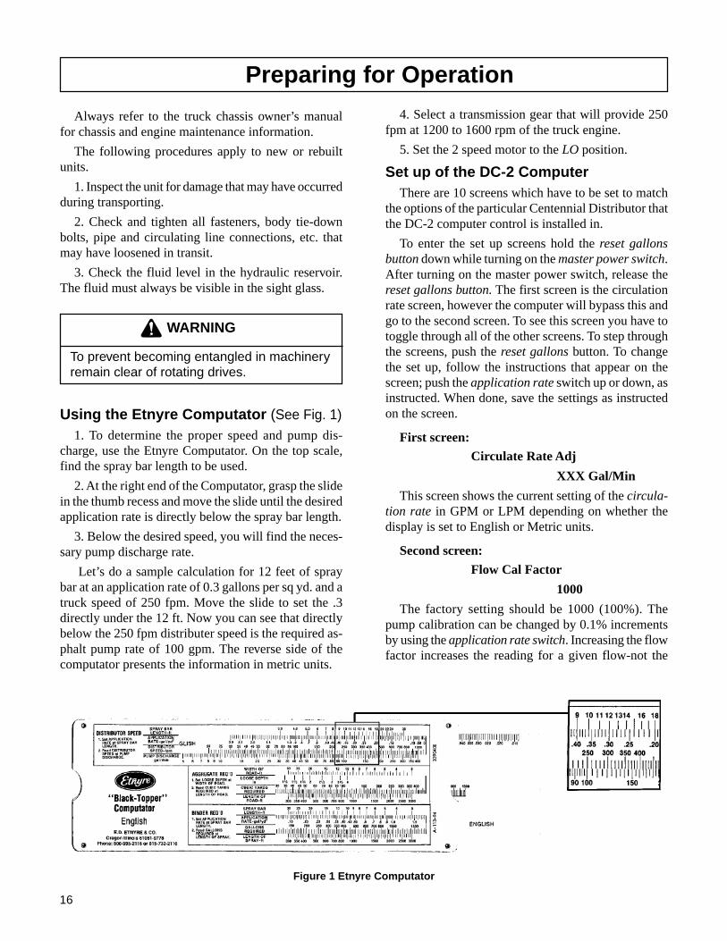
Using the Etnyre Computator (See Fig. 1)1. To determine the proper speed and pump dis-
charge, use the Etnyre Computator. On the top scale,find the spray bar length to be used.
2. At the right end of the Computator, grasp the slidein the thumb recess and move the slide until the desiredapplication rate is directly below the spray bar length.
3. Below the desired speed, you will find the neces-sary pump discharge rate.
Let’s do a sample calculation for 12 feet of spraybar at an application rate of 0.3 gallons per sq yd. and atruck speed of 250 fpm. Move the slide to set the .3directly under the 12 ft. Now you can see that directlybelow the 250 fpm distributer speed is the required as-phalt pump rate of 100 gpm. The reverse side of thecomputator presents the information in metric units.
Preparing for Operation
Figure 1 Etnyre Computator
4. Select a transmission gear that will provide 250fpm at 1200 to 1600 rpm of the truck engine.
5. Set the 2 speed motor to the LO position.
Set up of the DC-2 ComputerThere are 10 screens which have to be set to match
the options of the particular Centennial Distributor thatthe DC-2 computer control is installed in.
To enter the set up screens hold the reset gallonsbutton down while turning on the master power switch.After turning on the master power switch, release thereset gallons button. The first screen is the circulationrate screen, however the computer will bypass this andgo to the second screen. To see this screen you have totoggle through all of the other screens. To step throughthe screens, push the reset gallons button. To changethe set up, follow the instructions that appear on thescreen; push the application rate switch up or down, asinstructed. When done, save the settings as instructedon the screen.
First screen:Circulate Rate Adj
XXX Gal/Min
This screen shows the current setting of the circula-tion rate in GPM or LPM depending on whether thedisplay is set to English or Metric units.
Second screen:
Flow Cal Factor
1000
The factory setting should be 1000 (100%). Thepump calibration can be changed by 0.1% incrementsby using the application rate switch. Increasing the flowfactor increases the reading for a given flow-not the

17
This screen allows for adjusting the target currentfor the start of spraying. This number can be adjustedup or down. A higher number will give a more aggres-sive start when the master spray switch is turned on. Alower number will give a more gentle start. The num-ber on each distributor needs to be set to match the cur-rent in milliamps that is required to just start the as-phalt pump turning. Refer to engineering instruction#9100411 or the service video for detailed instructionson how to find the right value for the threshold.
Ninth screen:
3.1 to 1 Ratio
Decrease to Change
While there is no gearbox, this must be set to 3:1.
Tenth screen:Spray Delay
0.2
Sets the spray delay to allow for the 4-way valve tobe moved before opening the spray nozzle valves. Thespray delay should be set to 0.2 seconds using the ap-plication rate switch.
Eleventh screen:
EXIT=PUSH APP INC
SAVE=PUSH APP DECR
This screen allows you to return to the operatingmode, or saving the setting and returning to the operat-ing mode. Push down and hold the application rateswitch to save the settings. When the screen changes,release the switch. Push up to exit without saving.
WARNING
To prevent severe injury from becomingentangled in machinery: Stand clear ofrotating drives
WARNING
To prevent possible burns to operators orbystanders, or possible equipment damage,do not start any operation if any controlsettings are unknown.
CAUTION
To prevent damage to the asphalt pump, donot run pump for more than 5 minuteswithout bitumen to supply lubrication
flow. Decreasing the flow factor decreases the readingfor the given flow. Use the application rate switch tochange. Only make a change is you are absolutely surethat the calibration is incorrect.
Third screen:
Speed Cal Factor
100
This screen shows a ground speed radar calibrationfactor. The factory setting should be 100. The groundspeed calibration can be changed in 1% increments. Bychanging this factor. Increasing the speed factor willincrease the reading for a given speed and decreasingthe speed factor will decrease the reading for a givenspeed. Use the application rate switch to change.
Fourth screen:English Units
Decrease to Change
This screen allows you to change the display unitsto Metric or English. Push the application rate switchdown to change to Metric units and if it is set to Metricunits, push the application rate switch up to change toEnglish units.
Fifth screen:Series 40 Pump
Decrease to Change
This screen sets the type of hydrostatic pump thatthe machine has. Push the application rate switch downto change to the 90 Series and push the application rateswitch up to select the 40 Series.
Sixth screen:
1 ft controls
Decrease to Change
This screen selects between 1 foot controls or gangbar controls. Push the application rate switch down tochange to gang bar. If the control is set to gang barcontrol push the application rate switch up to changeto 1 ft controls.
Seventh screen:
Pulses/Gallon Adjust
65
This screen allows for changing the number of pulsesper gallon being fed to the computer. This numbershould be set to 65 (17 for metric).
Eighth screen:
Threshold Adjust
16

18
Engaging Pump on PTO EquippedDistributors
Before getting into the cab, check to make sure thatthe front/rear pump control switch on the rear controlpanel is in the forward position.
Start the truck engine with the transmission in neu-tral and engage the PTO. On trucks with a manual trans-mission, depress the clutch and pull outward or upwardon the PTO control knob. Slowly let the clutch up, ifthe PTO fails to engage, depress the clutch pedal andpull up on the PTO handle until engagement occurs.Or, depress the electric air shift PTO switch if yourvehicle is so equipped. Increase the engine rpm to afast idle.
On trucks with an automatic transmission, push downon the foot brake pedal, move the gear selector to anyforward gear and pull upward or outward on the PTOcontrol knob. Or depress the electric air shift PTO switchif your vehicle is so equipped. When the PTO engages,move the gear selector to neutral.
If the PTO fails to engage, continue pulling on theknob while releasing the brake pedal slightly, allowingthe truck to inch forward until the PTO engages andthen move the gear selector back to neutral.
Ensure that the truck parking brake is engaged be-fore leaving the cab.
WARNING
To prevent an explosion or fire hazard: Donot heat the material beyond themanufacturer’s recommended temperature.
CAUTION
To prevent possible damage to equipmentfrom material setting up in hose or distributor,ensure that bitumen in supply tank is heatedsufficiently.
WARNING
To prevent possible burns: Use extremecaution when using a torch to heat the pump.Asphalt accumulated around the pump mayignite when heating the pump with a torch.
FoamingIf the distributor is to be filled with hot bitumen,
proceed very cautiously. If there is any moisture in thetank, or if an emulsion product was the last load, foam-ing or eruption may occur.
Dow-Corning DC-200 may be used to prevent foam-ing in Distributors, Transports, and Maintenance Units.
Mix the contents of one can (16 oz.) with one (1)gallon of diesel fuel or kerosene. Add one (1) oz. ofthis diluted mixture to each 1000 gallons of asphalt.The correct amount may be poured through the man-hole. This will assist in reducing foaming, particularlyif moisture is present or if an emulsified asphalt wasused in a previous load.
If foaming does not occur at the start of the fillingoperation, but you suspect that there may be moisturein the spray bar or circulating system, the filling opera-tion should be stopped when the tank is no more than25% full. The product should then be circulated throughthe spray bar at a rate of 80 to 100 GPM before con-tinuing the filling operation.
If foaming does occur, continue circulating until thefoaming stops, and then suck back the product in thespray bar back into the tank before filling the tank therest of the way.
Asphalt InstituteTo further increase awareness of the hazards associ-
ated with the operation of a bituminous distributor, andbefore beginning initial operation, the operator shouldalso receive instruction by an authorized Etnyre dealer,or Etnyre representative.
The Centennial Distributor is designed to handle anumber of different products, such as AC’s, cutbacks& emulsions.
Knowledge of these liquid asphalts is required forsafe operation of the distributor. It is critical to knowwhich product can be loaded after the previous prod-uct, and which products react with each other.
The Asphalt Institute is a source of asphalt handlingsafety information.
Asphalt InstituteResearch Park DrivePO Box 140052Lexington, KY 40512-4052606-288-4960

19
Tank CapacityThe Centennial Distributor is designed to pump and
spray a variety of asphalt products in an efficient anduser friendly manner with great accuracy. The Centen-nial Distributor utilizes a computer to sense the vehicle’sground speed and control the hydrostatically drivenasphalt pump to maintain the set application rate, re-gardless of variations in vehicle speed or spray bar widthin use.
For a complete description of each of the controlsand how to set up the machine, refer to the set sectionof this manual.
WARNING
To prevent possible personal injury: Do notload the vehicle beyond the GAWR orGVWR. The maximum load volume must becalculated based on material density
The Centennial Distributor tank has a built-in airspace, or expansion space, above the “Tank Full” level.This air space is designed to minimize the chance thatthe tank will overflow if the material in the tank ex-pands due to heating or foaming. This air space shouldnot be used to carry product. The “Tank Full” level isbased on the vehicle’s axle ratings, and, GVWR at amaterial density of 7.7 lbs/gallon. A lower “tank full”must be calculated if a product with a density greaterthan 7.7 lbs/gallon is to be loaded. The lower “tank full”is calculated by multiplying the original “tank full” by7.7 and dividing the result by the new heavier productdensity.
If you suspect there may be moisture or emulsion inthe tank, Dow-Corning DC-200 additive can be usedto reduce foaming if a product being pumped is at atemperature in excess of 200ºF. Additional DC-200 ad-ditive may be obtained from E. D. Etnyre & Co. oryour Etnyre dealer.
Mixing Dow-Corning DC-200 Anti FoamAgent
Mix the contents of one can (16 oz.) with one (1)gallon of diesel fuel or kerosene. Add one (1) ounce ofthis diluted mixture to each 1000 gallons of asphalt.The correct amount may be poured through the man-hole. This will assist in reducing foaming, particularly
if moisture is present or if an emulsified asphalt wasused in a previous load.
If you suspect that there may be moisture in the spraybar or circulating system, the filling operation shouldbe stopped when the tank is no more than 25% full.The product should then be circulated from the tankthrough the spray bar for a minimum of 2 minutes at arate of 80 to 110 GPM before continuing the fillingoperation. After circulating product in the spray bar,suck back the material from the bar and then return tothe loading configuration and continue loading.
If foaming does occur, continue circulating until thefoaming stops, and then suck back the product fromthe spray bar into the tank before continuing the load-ing operation.
Filling Through the Fill Line
WARNING
To prevent possible burns from foaming orviolent eruption, do not load tank withmaterial temperature over 200ºF if water orcondensation is present in tank, or ifemulsion was used in the previous load. Donot heat material over 200ºF if moisture oremulsion is present in tank.
See the section on foaming on the previous page.
Connections and Preliminary Checks
WARNING
To prevent possible burns from leakingmaterial: Be sure all pipe, cap and hoseconnections are secure before openingvalves or beginning any operation..
WARNING
To prevent possible burns to operators orbystanders, or possible equipment damage,do not start any operation if any controlsettings are unknown.
GENERAL

20
WARNING
To prevent an explosion or fire hazard: Keepburning cigarettes or other sources ofcombustion away from manholes andoverflow vents.
WARNING
To prevent burns: Always wear eyeprotection, long sleeve shirt, insulatedgloves, boots, and long pants outside theboots when working around the distributor.
Ensure that both the fill line and the suction strain-ers are clean and properly installed.
Ensure that all connections between the distributorand the supply source are tight to prevent asphalt leaks.Air leaks will reduce the vacuum and slow down thefilling operation. The distributor is designed to suckasphalt through the fill line. Do not pressurize the fillline with an external pump.
WARNING
Before removing the fill line cap, makecertain that the asphalt pump is turning andthe suction valve is closed.
Filling from the CabIf you have not yet done so, read “Filling through
the fill line” before continuing.
1. Set all of the valve positions first. (See Fig 3)
2. Be sure that the master power switch is in the offposition to insure that nothing can function whileswitches are being set.
3. Turn the “Spray Bar” switch “off” to insure thatthe spray bar valves remain closed when the “Master”switch is turned back on..
4. The optional Front/Rear “Suction” switch can bein either position.
5. Place the Hyd Motor switch in the “Low” posi-tion.
6. Turn the “Rotary Actuator” knob to the “Load/Suckback” position. This positions the 4-way valve inthe “Load” position. If your distributor is not equippedwith a rotary actuator, at the rear of the distributor, placethe 4-way valve lever in the “Circulate in Tank” posi-tion. Figure 2 Using the Measuring Stick
At the rear panel:
Place the “Pump Control” switch in the “front” po-sition. This disables the rear panel pump control andmakes the front panel pump control active.
Place the “Suction Valve” switch in the closed posi-tion. This insures that the pump will not remove anymaterial from the tank.
Turn the “Master Power” switch “on” to enable thefront control panel.
7. At the cab panel, turn the “ Power” switch “on”.Both the front and rear power switches must be on tooperate.
8. Set the digital display to “GAL/SQ. YD; FPM;GPM” by using the “Change Display” button so youcan see the pumping rate displayed.
9. Run the engine at a minimum of 1100 RPM.
WARNING
To prevent possible burns from materialoverflow: Allow sufficient space in the tankfor expansion of the material when heating
10. Toggle the “Circulation Rate” switch up or downto obtain the desired rate. A pump rate of 75 GPM isrecommended to begin the loading operation. The pumprate can be increased at any time after loading has be-gun by using the circulation rate toggle switch. Depend-ing on material viscosity, as the loading rate is increased,the asphalt pump may cavitate. When this happens, thepump will make a distinctive sound, easily recognizedwith experience. Short periods of operation while thepump is cavitating will not damage the pump but you
00
100
"0"
End of stick touchestop of oil
Read amount ofmaterial in tankat top edge ofmanhole ring
Full
Using the Measuring Stick
The measuring stick is only accurate when the tank is level.

21
should not operate the pump in this condition for ex-tended periods. Higher speeds will not load thick ma-terial faster. Light materials or materials at sprayingtemperature, may be loaded at faster pump speeds.
WARNING
To prevent an explosion or fire hazard: Keepburning cigarettes or other sources ofcombustion away from manholes andoverflow vents.
11. Open the valve at the supply source and monitorthe tank gage. When the gage shows full, close the sup-ply valve.
12. After closing off the supply valve, While the dis-tributor pump is turning, carefully break the connec-tion between the supply source valve and the hose untilyou hear a vacuum and elevate the hose to allow maxi-mum drainage to the fill line.
WARNING
To prevent burns: Always wear insulatedgloves when handling spray bar sections orhoses.
13. Allow the pump to continue turning while thehose is disconnected from the fill line and the fill linecap is replaced and secured.
14. Reduce the pump rate to 0 using the circulationrate switch.
Filling from the Rear Control Panel1. Set all of the valve positions first.
2. Turn the “Power Switch” “on” at the cab controlpanel.
3. Put the motor speed switch in the Low position.
4. At the rear control panel, turn the “Pump Con-trol” knob fully counterclockwise to insure the pumpis at minimum speed before switching to the rear pumpcontrol.
5. Place the “Pump Control” switch to the “rear” po-sition to enable control of the pump from the rear.
6. Place the “Suction Valve” switch in the “Closed”position to prevent sucking material out of the tank.
7. Turn the “Master Power” switch “On”.
8. Adjust the “Pump Control” knob to get the de-sired rate.
A pump rate of 75 GPM is recommended to beginthe loading operation. The pump rate can be increasedat any time after loading has begun by using pump con-trol knob. Depending on material viscosity, as the load-ing rate is increased, the asphalt pump may cavitate.When this happens, the pump will make a distinctivesound, easily recognized with experience. Short peri-ods of operation while the pump is cavitating will notdamage the pump but you should not operate the pumpin this condition for extended periods.
Figure 3. Valve Positions for Filling Through the Fill Line
Suck Back
OffHand Spray
Hand Spray Valve Positions
Hand Spray ValveClosed
Right Suck Back ValveClosed
4 Way ValveCirculate in Tank
Suction ValveClosed
Left Suck Back ValveClosed
Suckback Control Lever(Manual Control)Pulled Out
Handspray ValveOff
Transfer ValveClosed
Suckback Control Cylinder(Air Operated)Closed
Transfer Line Suck BackValve Closed
Butterfly Valve LeverNormal Position
Flush ValveClosed

22
WARNING
To prevent burns: Always wear insulatedgloves when handling spray bar sections orhoses.
12. Allow the pump to continue turning while thehose is disconnected from the fill line and the fill linecap is replaced and tightened.
Filling through the ManholeBe sure that the suction valve switch is in the closed
position before starting to fill the distributor throughthe manhole.
Set all of the valve positions first.
To reduce the risk of accidental discharge of asphalt,the asphalt pump should not be running when fillingthrough the manhole. When the gage shows full, closethe supply valve
WARNING
To prevent possible injury: Always open themanhole cover slowly. Pressure build up inthe tank may cause the cover to burst open.
Figure 4. Valve Positions for Filling Through the Manhole
WARNING
To prevent possible burns from materialoverflow: Allow sufficient space in the tankfor expansion of the material when heating
Higher pump speeds will not load thicker materialsfaster. Lighter materials, or heavy materials which arealready at spraying temperature, may be loaded at fasterrates.
WARNING
To prevent an explosion or fire hazard: Keepburning cigarettes or other sources ofcombustion away from manholes andoverflow vents.
9. Open the valve at the supply source and monitorthe tank gauge. When the gauge shows full, Close thesupply valve
10. After closing the supply tank valve, while theasphalt pump is still turning, carefully break the con-nection between the supply source valve and the hoseuntil you hear a vacuum and elevate the hose to al-low maximum drainage to the fill line.
11. Disconnect the hose at the supply end and el-evate the hose to allow maximum drainage of the prod-uct into the fill line.
SUCK BACK
OFF
HAND SPRAY
Hand Spray Valve Positions
Hand Spray ValveClosed
Right Suck Back ValveClosed
4 Way ValveCirculate in Tank
Suction ValveClosed
Left Suck Back ValveClosed
Suckback Control Lever(Manual Control)Pulled Out
Handspray ValveOff
Transfer ValveClosed
Suckback Control Cylinder(Air Operated)Closed
Transfer Line Suck BackValve Closed
Butterfly Valve LeverNormal Position
Flush ValveClosed

23
Circulating Product in the Tank
WARNING
To prevent an explosion or fire hazard: Keepburning cigarettes or other sources ofcombustion away from manholes andoverflow vents.
Circulating in the tank from the cabSet all of the valve positions first .
In the cab
Be sure that the “Power” switch is in the “Off” posi-tion to insure that nothing can function while switchesare being set.
Turn the “Spray Bar” switch “Off” to insure that thespray bar valves remain closed when the master powerswitch is turned back on.
Place the hydraulic motor switch in the “Low” posi-tion.
Turn the “Rotary Actuator” to the “Circulate in Tank”position to position the 4-way valve in the circulate intank position. If your distributor is not equipped with a
rotary actuator, at the rear of the distributor, place the4-way valve lever in the “Circulate in Tank” position.
The optional “Front/Rear Suction” switch can be ineither position.
At the rear control panel.
a. Place the “Pump Control switch in the frontposition to supply power to the cab pump control.
b. Place the “Suction Valve” switch in the“Open” position to open the suction valve.
c. Turn the “Master Power” switch “On”.
At the cab control panel, turn the “Power” switch“on”
Set the digital display to “GAL/SQ. YD; FPM; GPM”by using the “Change Display” button.
WARNING
To prevent possible burns from materialoverflow: Allow sufficient space in the tank forexpansion of the material when heating
Toggle the “Circulation Rate” switch up or down toobtain a rate of 100 to 150 GPM which is the recom-mended rate for heating operations.
Figure 5 Valve Positions for Circulating in the Tank
Suck Back
Off
Hand Spray
Hand Spray Valve Positions
Hand Spray ValveClosed
Right Suck Back ValveClosed
4 Way ValveCirculate in Tank
Suction ValveOpen
Left Suck Back ValveClosed
Suckback Control Lever(Manual Control)Pulled Out
Handspray ValveOff
Transfer ValveClosed
Suckback Control Cylinder(Air Operated)Closed
Transfer Line Suck BackValve Closed
Butterfly Valve LeverNormal Position
Flush ValveClosed

24
WARNING
To prevent possible burns: Use extremecaution when using a torch to heat the pump.Asphalt accumulated around the pump mayignite when heating the pump with a torch
If the product is too cold to be circulated, some heat-ing with the burners will be needed to increase the tem-perature enough to be able to start circulating. Refer tothe portion of this operating manual for instructions onyour particular type of burner.
WARNING
To prevent an explosion or fire hazard: Whenthe burners go out, shut off the fuel supply toboth burners and allow the flues to ventilatefor at least 3 minutes before re-lighting theburners
WARNING
To prevent an explosion: Do not operate theburners when the vehicle is unattended,when the vehicle is in motion, or with thevehicle in a confined area
Figure 6. Valve Positions for Circulating in the Bar
Circulating in the Tank from the RearControl Panel
Before going to the cab to turn the Master Powerswitch on, be sure that the Power switch in the rearpanel is “Off”.
In the cab turn the “Power Switch” to the “On” posi-tion.
Put the hydraulic motor switch in the low position.
Turn the “Rotary Actuator” knob to the “Circulatein Tank” position. If your distributor is not equippedwith a rotary actuator, at the rear of the distributor, placethe 4-way valve lever in the “Circulate in Tank” posi-tion.
At the rear control panel, turn the “Pump Control”knob fully counterclockwise, place the “Pump Control”switch in the “Rear” position.
Turn the “Master Power” switch “On”.
Place the “Suction Valve” in the “Open” position.
Adjust the “Pump Control” to obtain the desired rate.100 to 150 GPM is recommended for heating opera-tions.
Suck Back
OffHand Spray
Hand Spray Valve Positions
Hand Spray ValveClosed
Right Suck Back ValveClosed
4 Way ValveCirculate in Bar
Suction ValveOpen
Left Suck Back ValveClosed
Suckback Control Lever(Manual Control)Pulled Out
Handspray ValveOff
Transfer ValveClosed
Suckback Control Cylinder(Air Operated)Closed
Transfer Line Suck BackValve Closed
Butterfly Valve LeverNormal Position Flush Valve
Closed

25
Circulating Product in the Bar
WARNING
To prevent an explosion or fire hazard:Ensure that the burners are extinguishedbefore removing any material from the tankin any manner. Liquid petroleum (LP)burners can support a flame for severalminutes after the fuel supply is turned off.
1. Set all of the valve positions first.
Perform the procedure for circulating in the tank first.Then move the rotary actuator knob to the “Circulatein Bar” position. If your distributor is not equipped witha rotary actuator, at the rear of the distributor, place the4-way valve lever in the “Circulate in Bar” position.The circulate in tank procedure can be performed fromeither the cab or the rear control panel.
CAUTION
To prevent excessive pressure in the spraybar, the asphalt pump speed should notexceed 160 GPM while circulating in thespray bar.
Circulate product long enough to ensure removal ofall air from the bar and to heat the spray bar valvessufficiently. Material will circulate in the bar endswhether the wings are folded or extended.
Spraying OperationsA correct spray pattern cannot be obtained unless
the product is heated to its proper spraying tempera-ture. Cold product will not provide sharp spray edges,and will cause streaking. If heating of the product isrequired, refer to the section of this manual on “Heat-ing Product in Distributors” or your Operator’s Manualfor instruction on operation of your particular type ofburners.
The DC-2 computer automatically adjusts the asphaltpump speed to deliver the correct amount of asphaltfor the application rate, spray width and vehicle speed.The circulation rate in the bar when not spraying shouldbe set to 50% of the pump speed while spraying. Thiscirculation rate will allow the asphalt pump to reachthe desired speed quickly when spraying is started. Cir-culation rates higher than 50% will result in a heavierstart while rates below 50% will produce a lighter start.
WARNING
To prevent an explosion or fire hazard: Ensurethat the burners are extinguished beforeremoving any material from the tank in anymanner. Liquid petroleum (LP) burners cansupport a flame for several minutes after thefuel supply is turned off.
To prevent an explosion: Do not operate theburners when the vehicle is unattended,when the vehicle is in motion, or with thevehicle in a confined area.
To prevent an explosion or fire hazard: Whenthe burners go out, shut off the fuel supply toboth burners and allow the flues to ventilate forat least 3 minutes before re-lighting theburners.
To prevent an explosion or fire hazard: Do notheat the material beyond the manufacturer’srecommended temperature.
To prevent an explosion or fire hazard: Keepburning cigarettes or other sources ofcombustion away from manholes and overflowvents.
To prevent possible hand or facial burns:Always light the inside burner first. Do notreach across a lit burner to light or re-light theinside burner. Shut off the outside burnerbefore lighting the inside burner.
To prevent possible burns from materialoverflow: Allow sufficient space in the tank forexpansion of the material when heating
To prevent possible burns to operators orbystanders, or possible equipment damage, donot start any operation if any control settingsare unknown.
To prevent possible burns from leakingmaterial: Be sure all pipe, cap and hoseconnections are secure before opening valves.

26
WARNING
To prevent possible burns from hot asphaltspray: Do not stand, or allow anyone to stand,where accidental opening of a valve maycause contact with hot asphalt.
Spray bar nozzles have a limited flow range at whichoptimal performance will be achieved. Flow ratesgreater than this optimal range will cause excessivefogging. Rates that are too low will cause the fan tosag and cause heavy edges. Refer to the nozzle selec-tion chart in the operator’s manual to select the nozzlesappropriate for your conditions.
Adjusting the Spray Bar Nozzle AngleAdjust the nozzles to obtain an angle of approxi-
mately 30 degrees with the spraybar centerline. Everynozzle should be at the same angle. A nozzle adjust-ment wrench is supplied with each new unit.
Figure 7. Adjusting the Spray Bar Nozzles
Figure 8. Adjusting the Spray Bar Height.
Adjusting the Spray Bar HeightLower the spraybar and adjust the down stops so that
the nozzles are approximately 12” above the road, onthe main bar with both wings folded, when the tank isempty. At this height, the spray fans from the nozzleswill overlap to provide triple lap coverage of materialon the ground. This is the normal spraying height. Lowerthe wings and adjust them with the cylinder nuts to fol-low the crown of the road. The spray bar should be at anangle of 100 to 105 degrees with the surface of the roadwhen viewed across the road. This slight rearward tra-jectory compensates for the forward movement of thedistributor to evenly coat the front and back sides ofprojections on the road surface.
Spraying through the BarBefore spraying, place the valves in position for spray-
ing.
At the Rear Panel
a. Put the “Pump Control” switch in the “Front” po-sition.
b. Put the “Suction Valve” in the “open” position.
c. Turn the “Master Power” switch “on”.
If the distributor is equipped with a gang spray bar
a. Change the display to “Bar Ft.” using the “ChangeDisplay” button.
b. Toggle the “Application Rate” switch to obtain thedesired bar width.
c. Adjust the spray bar valves to the same width se-lected in the cab, using the flip levers on each nozzlevalve. Disengage the flip lever from the buss bar pin todeactivate the nozzle.
d. Press the “Change Display” switch to show the“Application Rate” screen.
If equipped with 1 foot controls, select the desiredspray bar sections to spray by placing the appropriateswitches in the “On” or up position.. The spray bar valvescorresponding to the selected bar switches will openwhen the “Spraybar” switch is turned on. Individualswitches may be turned on or off during the spray op-eration, and the DC-2 computer will adjust the pump-ing rate to maintain the desired Application Rate.
Turn the “Master Power” switch “On”.
Put the hydraulic motor switch in the “Low” posi-tion.
Choose the desired application rate by depressing theappropriate “Memory” button or by toggling the “Ap-plication rate” switch up or down to obtain the desired
30º

27
spraying, the truck speed does not have to remain con-stant to maintain the application rate accuracy. At higherspeeds, flow rates can increase beyond the nozzle flowrating. When this occurs, fogging will result and youshould slow down. At lower speeds, the flow rate maydecrease below the recommended nozzle flow rating.When this occurs, the fan droops causing incompleteoverlapping, heavy edges and streaking.
When the end of the shot is reached, turn the “SprayBar” switch “off” or down. The 4-way valve is auto-matically returned to the “Circulate in Bar” positionwhen the spray bar is turned off.
During the periods between shots, material shouldbe circulated in the spray bar to keep the bar warm andprevent material set up in the bar. However, materialshould not be circulated in the bar when travelling fromlocation to location. If you want to shut the distributordown at the end of the day or between shots, you mustsuck back the system. Refer to the suck back portion ofthis manual for instructions.
CAUTION
Do not run the pump above rated capacity of400 GPM. Damage to equipment may occur.
Setting the Digital Memory PresetsSetting the digital memory presets is not required to
spray. The memory buttons offer the operator a conve-
application rate on the digital display. The ApplicationRate may be changed while spraying simply by usingthe “Application Rate” toggle switch. You may returnto the original application rate at any time by eitherusing the toggle switch or depressing the proper presetmemory button. Engage the PTO if the distributor hasa PTO driven hydrostatic pump. Before moving the bar,circulate some hot material through the bar. This al-lows the bar to warm up and also extends the life of thebar seals and o-rings.
Prior to setting the “Rotary Actuator” to the “Circu-late in Bar” position, decrease the asphalt pump flowrate to a maximum of 160 GPM, to avoid excessivepressure in the spray bar when you are not spraying. Ifyour distributor is not equipped with a rotary actuator,at the rear of the distributor, place the 4-way valve le-ver in the “Circulate in Bar” position. The circulationrate in the bar when not spraying, should be set to 50%of the spray rate, but not greater than 160 gpm. Whenthe desired application rate is set in the computer, placethe “Rotary Actuator” in the “Circulate in Bar” posi-tion and allow the material to circulate in the bar for afew minutes to warm up the bar, valves and nozzles.Lower the spray bar and continue to heat to bring thespray bar up to operating temperature.
Put the truck transmission and rear axle in the propersettings for the shot.
Start the distributor moving in the pre selected gear.
At the start line of the shot, move the “Spray Bar”switch to the “On” position. While the distributor is
Figure 9. Valve Positions for Spraying Through the Spray Bar.
Suck Back
OffHand Spray
Hand Spray Valve Positions
Hand Spray ValveClosed
Right Suck Back ValveClosed
4 Way ValveCirculate in Bar
Suction ValveOpen
Left Suck Back ValveClosed
Suckback Control Lever(Manual Control)Pulled Out
Handspray ValveOff
Transfer ValveClosed
Suckback Control Cylinder(Air Operated)Closed
Transfer Line Suck BackValve Closed
Butterfly Valve LeverNormal Position
Flush ValveClosed

28
WARNING
To prevent possible burns from hot asphaltspray: Do not stand, or allow anyone tostand, where accidental opening of a valvemay cause contact with hot asphalt.
After sucking back for approximately 2 minutes,open the end valves on the spray bar momentarily to letair into the system. You must hear a positive indicationof vacuum for proper suckback.
Close the suckback valves.
Reduce the asphalt pump speed to 100 gpm.
Open the self-flush valve located on the strainer box.This will allow diesel fuel to enter the system and washout the pump.
After 2 minutes, shut the self-flush valve.
Turn the “Master Power” switch off.
If the unit is equipped with auto wash option, turnthe electric pump on with the flush valve open and as-phalt pump turned off and run for 2 minutes. This willplace a quart of diesel fuel on top of the asphalt pumpfor better starts after long periods of shutdown.
If not equipped with the electric pump, it is helpfulto pour some diesel fuel down the fill line after all op-erations are completed. The diesel fuel will remain inthe pump overnight to keep the pump free for the nextmorning’s operation.
Figure 10. Valve Positions for Suck Back of the Spray Bar.
nient way to store 5 different preset application rates.These settings are saved in the memory even after themaster power switch has been shut off.
To store an application rate in a memory location,set the digital display to “Gal/Sq Yd using the “ChangeDisplay switch.
To set a memory, push that preset button in and holdit in. While holding it in, set the application rate to thedesired value using the “Application Rate” toggleswitch. To raise the application rate hold the applica-tion rate switch up and to lower the application rate,hold the application rate switch down. When you havethe application rate set to the desired value, release thememory button. The displayed application rate will bestored in that memory location until it is over writtenwith a new application rate using the same procedure.
Suckback from the CabSet all of the valve positions first.
Raise the spray bar and fold the wings up.
Turn the “Rotary Actuator” knob to the “Load/Suck-back” position. If your distributor is not equipped witha rotary actuator, at the rear of the distributor, place the4-way valve lever in the “Circulate in Tank” position.
Run the pump at 200 gpm using the circulation rateswitch in the cab or set the pump control to “rear” andadjust the pump speed with the rear pump control knob.Remember the gpm reading is displayed only in thecab.
Suck Back
OffHand Spray
Hand Spray Valve Positions
Hand Spray ValveClosed
Right Suck Back ValveOpen
4 Way ValveCirculate in Tank
Suction ValveClosed
Left Suck Back ValveOpen
Suckback Control Lever(Manual Control)Pushed In
HandsprayValveOff
Transfer ValveClosed
Suckback Control Cylinder(Air Operated)Extended
Transfer Line Suck BackValve Closed
Butterfly Valve LeverNormal Position
Flush ValveClosed

29
Ensure that the self flush valve is closed at the endof this function, or before loading or circulating asphaltto eliminate chances of inducing asphalt into the selfflush fuel tank.
HandsprayingBefore spraying, place the valves in position for
handspray.
WARNING
To prevent burns from hot asphalt whenhandspraying: Hold the handspray gun inproper position and watch for other people.
WARNING
To prevent burns: Always wear eyeprotection, long sleeve shirt, insulatedgloves, boots, and long pants outside theboots when working around the distributor.
At the rear panel, turn the master power switch off.
In the cab
Turn the “Rotary Actuator” knob to the “Circulatein Tank” position. If your distributor is not equipped
with a rotary actuator, at the rear of the distributor, placethe 4-way valve lever in the “Circulate in Tank” posi-tion.
Turn the spray bar switch “off”.
Turn the “Power” switch “On”.
At the rear panel, turn the Master Power switch onand place the “Suction Valve” switch in the “Open”position.
Adjust the asphalt pump speed to 80 GPM using the“Circulation Rate” switch in the cab, or set the “PumpControl” switch to “rear” and adjust the pump speedwith the “Pump Control” knob. Remember, the GPMreading is only available in the cab of the distributor.
CAUTION
When using rear pump control, engine RPMchanges will affect asphalt pump speed
Turn the handspray valve on the spray wand 90 de-grees to spray.
Adjust the handspray pressure with the “Butterfly”valve. Turn the “Butterfly” valve counter clockwise (towards transfer) to increase the handspray pressure.Do not turn the handle of the “Butterfly” valve com-pletely to the “Transfer” position as this will cause the
Figure 11. Valve Positions for Handspray.
Suck Back
Off Hand Spray
Hand Spray Valve Positions
Hand Spray ValveClosed
Right Suck Back ValveClosed
4 Way ValveCirculate in Tank
Suction ValveOpen
Left Suck Back ValveClosed
Suckback Control Lever(Manual Control)Pulled Out
Handspray ValveHandspray
Transfer ValveClosed
Suckback Control Cylinder(Air Operated)Closed
Transfer Line Suck BackValve Closed
Butterfly Valve LeverHandspray Position
Flush ValveClosed

30
Suck back the asphalt from the handspray hose byturning the “Butterfly” valve to the “Normal” position.
Open the handspray suckback valve.
Increase the pump speed to approximately 200 GPM.
After approximately 1 minute, crack the handsprayvalve on the handspray wand “open”. Suck the hand-spray wand back for about 2 minutes. If finished hand-spraying for the day, crack open the handspray valvewith the nozzles submerged in flushing oil. Close thehandspray wand valve and shut off the pump.
Return all of the valves to their normal positions.
Figure 12 Valve Positions for Handspray Suckback
asphalt to dead head into the handspray hose when thehandspray wand is shut off.
If the “Butterfly” valve is approaching the completelyclosed position and pressure in the wand is insufficient,reset the “butterfly” valve to the “handspray” positionand increase the asphalt pump flow rate.
When finished hand spraying suck back the hand-spray system.
Suck Back for Hand Spray OperationsWhen finished hand spraying, set all valves and le-
vers to their positions for handspray suck back.
Turn the “Rotary Actuator” to the “Load/Suckback”position. If your distributor is not equipped with a ro-tary actuator, at the rear of the distributor, place the 4-way valve lever in the “Circulate in Tank” position.
Suck Back
OffHand Spray
Hand Spray Valve Positions
Hand Spray ValveOpen
Right Suck Back ValveClosed
4 Way ValveCirculate in Tank
Suction ValveClosed
Left Suck Back ValveClosed
Suckback Control Lever(Manual Control)Pulled Out
Handspray ValveSuckback
Transfer ValveClosed
Suckback Control Cylinder(Air Operated)Closed
Transfer Line Suck BackValve Closed
Butterfly Valve LeverNormal Position
Flush ValveClosed

31
When pump-off is complete, turn the “Butterfly”valve to the “Normal” position.
Close the transfer valve.
Decrease the pump speed to approximately 50 GPM.
Close the “Suction” valve.
Close the valve at the storage tank.
Open the suckback valve in the transfer line, andcarefully break the connection at the storage tank,between the storage tank valve and the fill hose toallow air into the hose.
WARNING
To prevent burns: Always wear insulatedgloves when handling spray bar sections orhoses.
Increase the pump speed to approximately 150 GPMfor 2 minutes.
Increase the pump speed to 200 GPM. Carefully andslowly disconnect the hose at the storage tank end andelevate the hose to allow the maximum drainage of as-phalt to the transfer line. Allow the pump to continueturning while the hose is carefully disconnected fromthe transfer line and the transfer line cap is replacedand secured.
Then shut the pump down and return the suckbackvalve to its normal position.
Pump Off OperationsConnect the pump-off hose from the storage tank to
the transfer line.
When preparing to pump off, ensure that all valvesin the pump-off line between the distributor and thestorage tank are open before opening the suction valveon the distributor.
Set all of the valves and levers to their proper posi-tions for pump-off.
Place the “Rotary Actuator” knob in the “Circulatein Tank” position If your distributor is not equippedwith a rotary actuator, at the rear of the distributor, placethe 4-way valve lever in the “Circulate in Tank”position.
Open the “Transfer” gate valve.
Open the “Suction” valve.
Increase the pump speed to approximately 150 GPMusing the “Circulation Rate” switch in the cab, or setthe “Pump Control” switch in the rear control box to“Rear” and adjust the pump speed with the “Pump Con-trol” knob. Remember that the GPM reading is onlyavailable in the cab.
Turn the “Butterfly” valve to the “Transfer” posi-tion, watch that the pump off hose does not becomeplugged.
If this happens return the Butterfly valve to the nor-mal position.
Figure 13. Valve Positions for Pump Off
Suck Back
OffHandSpray
Hand Spray Valve Positions
Hand Spray ValveClosed
Right Suck Back ValveClosed
4 Way ValveCirculate in Tank
Suction ValveOpen
Left Suck Back ValveClosed
Suckback Control Lever(Manual Control)Pulled Out
Handspray ValveOff
Transfer ValveOpen
Suckback Control Cylinder(Air Operated)Closed
Transfer Line Suck BackValve Closed
Butterfly Valve LeverTransfer Position
Flush ValveClosed

32
Slowly and carefully open the valve at the supplysource.
WARNING
To prevent burns: Always wear insulatedgloves when handling spray bar sections orhoses
Turn the “Rotary Actuator” to “Load Fill” or closethe suction valve.
Turn the “Butterfly” valve to the “Normal” position.
Close the valve at the storage tank.
Close the transfer valve.
Open the suckback valve on the transfer line.
Increase the pump speed to 200 GPM for about 2minutes. Disconnect the hose at the storage tank endand elevate it to allow maximum drainage of asphaltinto the transfer line.
Carefully break the connection between the valve,at the tank being filled, and the fill hose, to allow airinto the hose.
Allow the pump to continue to turn while discon-necting the hose from the transfer line and the transferline cap is replaced and tightened.
Figure 14. Valve Positions for Transfer
Transfer OperationsSet all of the valves and levers to their proper posi-
tions for transfer.
Connect the loading hose from the supply source tothe fill connection. Be sure that the connections are tight.
Connect the transfer hose from the transfer connec-tion to the storage tank. Be sure that the connectionsare tight.
Open the Suction valve with the switch at the rearpanel.
When preparing to transfer, be sure that all of thevalves in the pump off line between the distributor andthe storage tank are open before opening the valve onthe storage tank containing liquid.
Turn the “Rotary Actuator” to the “Circulate in Tank”position. If your distributor is not equipped with a ro-tary actuator, at the rear of the distributor, place the 4-way valve lever in the “Circulate in Tank” position.
Open the Transfer valve.
Increase the pump speed to approximately 150 GPMusing the “Circulation Rate” switch in the cab or setthe “Pump Control” switch at the rear control panel to“Rear” and adjust the pump speed using the “PumpControl” knob in the rear control panel.
Turn the “Butterfly” valve to the “Transfer” posi-tion.
Suck Back
OffHand Spray
Hand Spray Valve Positions
Hand Spray ValveClosed
Right Suck Back ValveClosed
4 Way ValveCirculate in Tank
Suction ValveClosed
Left Suck Back ValveClosed
Suckback Control Lever(Manual Control)Pulled Out
Handspray ValveOff
Transfer ValveOpen
Suckback Control Cylinder(Air Operated)Closed
Transfer Line Suck BackValve Closed
Butterfly Valve LeverTransferl Position
Flush ValveClosed

33
Flushing OperationsSet all of the valves and levers to their proper posi-
tions for flushing.
Turn the “Rotary Actuator” to the “Load/Suckback”position. If your distributor is not equipped with a ro-tary actuator, at the rear of the distributor, place the 4-way valve lever in the “Circulate in Tank” position.
Ensure that the suction valve is closed.
Open the self-flushing valve and run the pump atapproximately 100 GPM.
After 2 minutes, close the self flush valve.
Normally the suckback procedure will remove suf-ficient material from the circulating system to negatethe need for draining the circulating system and spraybar before proceeding with the wash out operation. Theflushing operation requires only 3 quarts of flushingsolvent. This small amount is not sufficient to fill thelines to the tank, thus preventing solvent from beingforced into the tank.
A common practice following completion of theflushing procedure and subsequent shutdown is to pour1 to 2 quarts of solvent into the fill line. This softens ordissolves the residual asphalt in the pump. Allow thesesolvents to remain in the system until the next use.
If unit has electric washdown option, open flushvalve and turn on electric pump for 2 minutes. Thiswill pump 2 quarts of diesel fuel on top of the asphaltpump.
Figure 15. Valve Positions for Flushing
Suck Back
OffHandSpray
Hand Spray Valve Positions
Hand Spray ValveClosed
Right Suck Back ValveClosed
4 Way ValveCirculate in Tank
Suction ValveClosed
Left Suck BackValveClosed
Suckback Control Lever(Manual Control)Pulled Out
Handspray ValveOff
Transfer ValveClosed
Suckback Control Cylinder(Air Operated)Closed
Transfer Line Suck BackValve Closed
Butterfly Valve LeverNormal Position Flush Valve
Open

34
LPG Supply Tank RequirementsUse only liquid withdrawal type supply tanks for your
LPG burners.
Two types of LPG supply tanks are available: tanksfor liquid type burners and tanks for vapor type burn-ers. The LPG burners on your Etnyre distributor re-quire a supply tank for liquid type burners. Liquid typeburners will operate from a vapor withdrawal tank,however the amount of heat delivered will be dramati-cally reduced, and the life of the burner will be short-ened.
There are three different types of LPG burners:manual control burners, burners with outfire control,and burners with automatic ignition and temperaturelimiting control.
Manual Control BurnersThere are four valves associated with operation of
the manual control burners: one at the supply tank, andthree in the burner piping.
The two smaller valves (one at each burner) arebleeder type valves with a small hole drilled throughthe valve case. Propane liquid is supplied to the bleedervalve directly from the supply tank shutoff valve. Be-cause of the bleeder hole in this valve, it is NOT pos-sible to shut off all of the fuel to the lower burner byshutting the main valve at the burners. The main burnervalve will only shut off the upper burner. The lowerburner must be shut off using the supply tank valve.
WARNING
Always shut off burners using the mainshutoff valve on the supply tank
The large valve located in the fuel line to the outsideor upper burner is a positive cut off valve that allowsall fuel to be cut off to the bleeder valve on the outsideburner only.
Burner OperationBe sure that the main supply valve and the main
burner valves are fully closed and the bleeder valvesare turned fully clockwise before starting.
Open the dampers in the flue exhaust stacks.
Open the valve at the supply tank and immediatelylight the inside burner. As soon as the burner lights,open the bleeder valve. No preheating is necessary.
Heating Asphalt with Liquid PropaneGas (LPG) Burners
IMPORTANT
Circulating the asphalt in the tank while heatingis recommended for faster heating andreduced carbon formation on the flues. Onlywhen the asphalt pump is “Frozen” is itacceptable to operate the burners withoutcirculating asphalt in the tank. However, if theasphalt pump is frozen, carefully apply heat tothe pump and start circulating the material assoon as possible.
WARNING
Residual fuel in LPG burners will support a flamefor several minutes after the fuel flow has beenshut off. After using LPG burners, confirm that allflame has been extinguished before attemptingany operation that could release flammablevapors.
Failure to ensure that the flame is completelyextinguished could result in an explosion or firethat can cause injury or death.
To prevent an explosion or fire hazard: Positionunit broadside to wind whenever possible toprevent volatile fumes from drifting towardburners
To prevent an explosion or fire hazard: FluesMUST be covered by a minimum of 6 inches ofmaterial when the burners are in operation.
To prevent an explosion or fire hazard: Do notremove material from tank in any manner whenthe burners are in operation.
To prevent an explosion or fire hazard: Do notdrive unit when burners are operating.
To prevent an explosion or fire hazard: Do notoperate burners if tank is damaged or leaking.
To prevent an explosion or fire hazard: Whenburners go out, allow flues to ventilate for severalminutes before relighting burners.
To prevent an explosion or fire hazard: Do notheat material beyond the manufacturersrecommended temperature.
To prevent foaming or violent eruption, do notheat material over 200ºF if moisture is present intank.
To prevent possible burns from material overflow,allow sufficient space in tank for expansion ofmaterial when heating.

35
IMPORTANT
When the main fuel valve is opened at thebottle or tank, there is an immediate trickle ofgas passing through the inside burnerbleeder valve. Light the burner immediately
Check the fuel pressure at the pressure regulator. Toomuch pressure for a small asphalt tank will waste fuel.Too little pressure will increase heating time. Some ex-perimentation with the pressure will allow you to de-termine the most efficient fuel pressure to use. The fol-lowing is a good rule of thumb.
1000-1250 gallon tank- 15 psi
1500-1750 gallon tank- 20 psi
2000-2250 gallon tank- 25 psi
2250-2500 gallon tank- 30 psi
2750 gallon and larger- 40 psi
If necessary, adjust the flame with the bleeder valveat the burner.
When the LPG burners are operating, the outside ofthe fuel line up to the first coil of the burner shouldfrost over. If no frost forms it is an indication that theburners are operating on vapor instead of liquid. Thiscondition must be corrected immediately to preventdamage to the burners.
If after the lines frost over, the flame starts to diedown and the frost melts off the fuel line, it is likelythat there is moisture in the fuel supply tank. Moisturein the fuel can form ice crystals that stop the fuel flow.Your local LPG supplier can add an anti-icing agent toprevent burner icing.
IMPORTANT
It is recommended that two persons beinvolved in lighting the first burner. When themain fuel valve is opened at the tank, thereis an immediate trickle of gas passingthrough the inside burner valve. The longerthe gas is allowed to collect in the flue, themore likely there will be a flashback whenthe burner is ignited. Having one person lightthe burner while the other opens the mainsupply valve will reduce the likelihood of aflashback.
WARNING
To prevent possible burns, always use atorch to light the burners. Never attempt tolight the burners with a match or pocketlighter.
WARNING
A fully charged dry chemical type fireextinguisher must be within easy reachwhenever the burners are operating or thereis an open flame near the distributor.Minimum dry chemical capacity of the fireextinguisher should be 10 pounds.
Figure 16. Manual Control Burner System

36
Burners With Outfire ControlsEquipment Design
The burner and the burner control valves are identi-cal to the manual operated burner system. However,burners with outfire controls are equipped with an out-fire control box. The outfire controls consist of two ther-mocouples, a push button start switch, an electric fuelsolenoid valve, a pressure regulator and a pressure gage.
The heat sensing thermocouples are positioned ineach burner. If either burner loses its flame, the ther-mocouple senses the drop in temperature, and deacti-vates the fuel solenoid, and the fuel to both burners isshut off.
The only operational differences between the manualburners and burners with the optional outfire controlsis the start up and shut down procedures. Unlike themanual burners, when the burners are equipped withoutfire controls, no fuel flows to the burners when themain solenoid shutoff valve is closed.
Burner Operation with Outfire ControlsTurn on the Master Power switches.
Open the dampers in the exhaust stacks.
Ensure that the main burner control valve is closedand that the bleeder valves for both burners are turnedfully clockwise.
IMPORTANT
It is recommended that two persons beinvolved in lighting the burners. One personshould hold the torch while the other personopens the valves and holds the pushbuttonin.
Open the main fuel supply valve at the tank.
No fuel will be flowing at this point.
As soon as the low fire is established at the innerburner, open the positive shutoff valve to the outsideburner and light the outside burner on low fire.
After 30 to 40 seconds, release the pushbutton andobserve the pressure gage. If the pressure starts to droprapidly, depress the pushbutton and hold it in for an-other 30 seconds. It may require a slight increase infuel to the outside burner to adequately heat the ther-mocouple. Once both of the thermocouples are heatedthe pushbutton can be released.
IMPORTANT
If there is at least 6” of material covering theentire length of the upper flue, the secondburner can be lit.
WARNING
To prevent possible burns, always use atorch to light the burners. Never attempt tolight the burners with a match or pocketlighter.
To ignite the second burner ensure that the bleedervalve on the burner is turned fully clockwise. Positiona lit torch at the burner nozzle and open up the positiveshutoff valve in the line to the burner. As soon as thelow fire is established, the bleeder valve can be opened.
Never leave operating burners unattended.
WARNING
When heating, temperatures within the tankcan vary. Shut the burners off when thethermometer reaches a reading 10ºF. lowerthan the desired temperature. Continue tocirculate & monitor temperature untiltemperature stabilizes. Add remaining heatby operating burners for short periods,monitoring stabilized temperature after eachperiod.
WARNING
Calibration of thermometers should beverified to be within + 2% of full scalereading annually.
Certification can be accomplished by aqualified laboratory or by comparingstabilized dial readings to the pencilthermometer reading. Replace anythermometer that does not meet the +2%accuracy requirement.
When the desired temperature is reached, close themain fuel supply valve, at the lpg tank, first. Allowthe burners to operate at full capacity until the fuel inthe line from the tank burns out, then close both bleedervalves and the positive shutoff valve for the outsideburner.
Close the exhaust stack dampers to prevent heat loss.

37
IMPORTANT
In order to activate the thermocouples, bothburners must be lit on low flame even if onlyone burner will be used for heating. Placethe ignition torch at the inside burner nozzleand depress the pushbutton in the outfirecontrol box. Continue to hold the pushbuttonin until both burners are lit.
If both burners are to be used for heating, you cannow open both bleeder valves. If only the inside burneris to be used for heating, open the bleeder valve on theinside burner and allow the outside burner to remainburning on low flame so the thermocouple will beheated. Remember, if either burner flame goes out, theoutfire control will shut the solenoid valve cutting thefuel off to both burners.
WARNING
A fully charged dry chemical type fireextinguisher must be within easy reachwhenever the burners are operating or thereis an open flame near the distributor.Minimum dry chemical capacity of the fireextinguisher should be 10 pounds.
Figure 17. Outfire Controlled Burner System
WARNING
When heating, temperatures within the tankcan vary. Shut the burners off when thethermometer reaches a reading 10ºF lowerthan the desired temperature. Continue tocirculate & monitor temperature untiltemperature stabilizes. Add remaining heatby operating burners for short periods,monitoring stabilized temperature after eachperiod.
When the desired product temperature is reached:
Close the main fuel supply valve at the tank.
After all the fuel is burned and there is no flame ateither burner, turn both bleeder valves fully clockwiseand close the positive cut off valve at the burners.
Close the exhaust stack dampers to prevent heat loss.
WARNING
Calibration of thermometers should beverified to be within + 2% of full scalereading annually.
Certification can be accomplished by aqualified laboratory or by comparingstabilized dial readings to the pencilthermometer reading. Replace anythermometer that does not meet the +2%accuracy requirement.

38
Figure 18 Burner System with Auto Ignition & Temperature Control
Burners with Automatic Ignition andTemperature Limiting Control
Equipment Description
The temperature limiting control box contains thetemperature limiting control components as well as theautomatic ignition circuitry.
The automatic ignition circuit consists of two 12Vcoils, two spark plugs, a pair of thermocouples, (one ateach burner), and a momentary pushbutton switch. The12V coils send high voltage to the spark plugs thatcauses sparks to arc intermittently at each pilot burnerwhenever there is fuel pressure in the line from the mainsupply tank. The thermocouples provide a signal thatindicates when there is a flame at the pilot burners. Themomentary pushbutton switch on the control box is usedto fire the main burners once the pilot burners have ig-nited and the thermocouples have been heated suffi-ciently.
The temperature limiting control circuit consists ofa temperature probe in the distributor tank that sensesthe asphalt temperature, a thermostatic switch in thecontrol box and a temperature adjustment dial on theface of the control box. When the temperature of theasphalt in the distributor is heated to the temperatureselected with the temperature adjustment dial, the ther-mostatic switch shuts down the burners.
Burner Operation with Auto Ignition &Temp Control
Open the dampers on the exhaust stacks
Ensure that all burner valves are closed.
With this type of control, the inside or lower burnermay be operated without opening the positive shut offvalve to the outside burner. If both burners are to beused, the positive shutoff valve should be opened.
Open the main fuel valve at the supply tank. Thespark plugs will begin to arc and will ignite the pilotburners.
Set the thermostat to the desired temperature.
Allow the pilot burners to heat the thermocoupleprobes for at least 2 minutes. When the pilot burnershave heated the thermocouples sufficiently the sparkerwill stop. Press the cycle button to fire the main burn-ers. The bleeder valves may then be opened.
On new or rebuilt units, monitor the product ther-mometer to make certain that the burners shut downwhen the desired temperature is reached. (as set on thetemperature adjustment dial. If the burners do not shutdown at the correct temperature, refer to “Calibratingthe Thermostat”.
Once the burner shuts off automatically, it will notrestart until the cycle button is again depressed.

39
Figure 19. Electric Burner System
To shut the system down: Close the main fuel sup-ply valve at the tank.
Increase the thermostat setting 50 to 75ºF higherand push the start button. This will bring on the mainburners and quickly burn off all of the fuel in the linebetween the tank and the control box. The pilot burn-ers may continue to burn for a short time after themain burners cut off. Do not draw material from thetank as long as there is a flame present.
Close the exhaust stack dampers.
Electric Driven Burner OperationOpen the dampers in the exhaust stacks.
To light the burner, turn on the “Lower BurnerPower” switch.
If upper burner operation is desired, turn on the “Up-per Burner Power” switch.
Do not heat the material higher than the sprayingtemperature recommended by the asphalt supplier.
To shut down the burners, turn off the burner powerswitches.

40

41
TROUBLESHOOTING
Trouble Cause Remedy
Spray Fogs Pump speed too fast for size of nozzle Lower pump speed or change nozzles. See“Establishing Flow Rate/Ground SpeedRatio.”
Spray Streaks Pump speed too slow. Increase pump speed. See “EstablishingFlow Rate/Ground Speed Ratio.”
Nozzles not at proper angle. Adjust angle of nozzles.
Spray bar at improper height Adjust spray bar height.above ground.
Material temperature too low. Heat material to correct temperature.
Spray Lacks Pressure Pump speed too slow. Adjust pump speed.
One or more control valves in incorrect Check position of all control valves. Be sureposition, not fully opened or closed, or all valves are fully opened or closed.leaking. Repair leaking valves as necessary.
Suction strainer plugged. Clean suction strainer.
All Nozzles Do Not Spray bar linkages not adjusted Adjust linkage.Cut Off Spray correctly.
Pump Will Not Turn, Material in tank or pump below Heat material to proper pump temperature.Or Turns Slowly. pumping temperature.
Air leak in suction line from reservoir Locate and repair leak.to filter to inlet of charge pump.
Hydraulic system pressure low. Raise pressure.
Low oil in hydraulic reservoir. Add hydraulic oil to correct level.
Spray bar valves set improperly. Correct spray bar valve settings.
Defective Hyd. motor. Check for excessive case drain in motor.Repair or replace defective components.
Hydraulic Oil Material in tank or pump below Heat material to proper pump temperature.Overheats. pumping temperature.
Air leak in suction line from reservoir to Locate and repair leak.
filter to inlet of charge pump.
Low oil in hydraulic reservoir. Add hydraulic oil to correct level.
Spray bar valves set improperly. Correct spray bar valve settings.

42
Trouble Cause Remedy
Spray Bar SupplyTube Ball Joints Leak Ball joint O-ring is loose. Replace ball joint O-ring.
Ball joint gaskets not fully seated. Circulate hot material through spray bar andsupply tubes while shifting spray bar fromside to side. This should seat gaskets andstop leaks. CAUTION: To prevent damageto equipment, do not allow flame to beapplied directly to gasket material.
Application RateVaries Quantity of material in tank not being Use Etnyre measuring stick for accurate
measured accurately. readings. Be sure tank is level whenmeasuring.
Suction strainer plugged. Clean suction strainer regularly.
Hydrostatic controls not firmly Ensure that all controls are firmly locked inpositioned. place.
Suck back valves not fully closed.

43
Burner Air Band Settings1. Close bulk air bank (outside diameter band).
2. Set end air band between 3.5 - 4.0 on scale (seefigure 21a).
3. Open covers or dampers on exhaust stacks.
WARNING
To prevent an explosion or fire hazard: Keeparea free of sparks or open flames whentesting burners.
Check Ignition Transformer Spark1. Turn on master power switch in rear control box.
2. Turn on Burner Power switch.
3. Hold an insulated screwdriver approximately 1to 1-1/2 inches above the two wire springs on the trans-former and hold the ignition switch down. It should bepossible to jump a spark across the 1 to 1-1/2 inch gap
Electrode Assembly Adjustments1. Adjust electrode assembly per Figure 20.
NOTE: Before installing electrode assembly, checkthat blower wheel turns freely and that all set screwsare tightened securely.
2. Install electrode assembly into air tube unit. Useescutcheon plate for mounting (see Figure 21).
Electrode
Nozzle3/16" to 1/8"
5/16" to 1/4"
3/16" to 5/32"
3"+ 1/16"-
Figure 20. Burner Electrode Adjustments
Hole For Fuel Line
Mounting Screw - slide plate againstmounting screw. This will positionnozzle in air tube.
Figure 21. Electrode Assembly Installation
MAINTENANCE
Figure 21a. Nozzle Adjustment

44
between the springs and the screwdriver. If unable togenerate a spark, check the voltage at terminal spadesof the 12 volt ignition control box. Voltage must be110 volts AC minimum. If voltage is incorrect or notpresent, check ground wiring.
4. Reposition ignition transformer and secure toburner housing.
Fire Burners1. Ensure that fuel oil pressure is 100 PSIG.
WARNING
To prevent an explosion or fire hazard: Fluesmust be covered by minimum 6 inches ofmaterial when burners are in operation.When testing burners, do not run burners formore than 15 seconds if tank is empty.
2. Hold ignition switch down until ignition occurs,and keep switch down for an additional 2 to 4 secondsbefore releasing.
3. Run burner for 15 seconds maximum, then shutdown.
Figure 22. Nozzle Angle Adjustment
Figure 23 Nozzle Height Adjustment
30º
Adjusting Spray Bar Nozzle Angle
Adjust nozzles to obtain an angle of approximately30° with bar centerline (see Figure 22). Every nozzleshould be at the same angle.
NOTE: A nozzle adjustment wrench is supplied inthe tool box of each new unit.
Adjusting Spray Bar Height
Lower spray bar and adjust so that nozzles are ap-proximately 12 inches above road when tank is empty.At this height spray fans will overlap to provide triplelap coverage. See Figure 23
NOTE: Under heavy wind conditions it may be nec-essary to lower spray bar further.

45
SERVICING THE ETNYRE P-15 PUMP
6. Next, measure the case bore vertically at a point2.8 inches from each side. The vertical measurementmust not exceed 5.660 inches. If any bore measure-ments exceed these limits, the entire pump must be re-placed.
7. If inspection indicates the pump case is accept-able, measure the outside diameter of the impeller gears.Measure the impeller gears from tooth point to toothpoint on teeth directly opposite each other. The mini-mum outside diameter of the gears should be 5.635inches. The minimum length of the gears should be3.628 inches.
8. If any impeller gear is undersize, the entire four-gear set must be replaced.
9. End plate gasket thickness should be 0.014 - 0.016inches.
10. Divider plate thickness should be 0.127 - 0.128inches.
Impeller Installation And PumpAssembly
Each impeller gear set uses a series of dots on thegear faces to indicate position of the gears within thepump. Refer to Figure 24 for proper positioning of thegears. The dots must face away from the divider plate(towards the ends of the pump). Install the impellers innumerical order.
Vacuum Check1. Flush pump with 3 quarts of diesel fuel through
fill line.
2. Set controls for filling operation.
3. Install vacuum gauge in fill line cap.
4. Operate pump at 140 GPM on pump tachometer.A vacuum reading of less than 5Hg. (inches of mer-cury) after 2 minutes of operation indicates a vacuumleak or a worn pump.
Pump Disassembly And Inspection1. Remove 20 capscrews from perimeter of pump
end plate (see Figure 24).
2. Install two capscrews in the threaded holed nearthe outer edge of the end plate at approximately the 5o’clock and 11 o’clock positions. Tighten thecapscrews evenly to force the endplate away from thepump body.
3. Remove the endplate, impeller shafts and impel-lers (gears) as an assembly.
4. Clean the interior of the pump case. Slide yourfingers across the interior surfaces of the case. If anarrow raised area can be felt midway between the frontand the rear of the case, the entire pump should bereplaced.
5. If there is no raised area, measure the bore of thecase at its widest point horizontally (side-to-side). Thismeasurement must not exceed 9.910 inches.
Figure 24 Etnyre Asphalt Pump
Dots on this end (4)
Dots on this end (2)
Dots on this end (1)
Dots on this end (3)
Divider Plate

46
Fuel DataFuel Weight Per Gallon BTU Content
#2 Fuel Oil 7.49 lbs 144,300 per gallon
Kerosene 6.97 lbs. 134,500 per gallon
Propane 4.20 lbs. 91,500 per gallon
Approximate Burner FuelConsumptionLow Pressure Fuel Oil
935,000 BTU @ PSI
6.5 GPH per burner
(144,000 BTU per gallon)
Kerosene Generating575,000 BTU @ 40 PSI
4.25 GPH per burner
(135,000 BTU per gallon)
Heating TerminologyFlash Point (Open Cup)
The temperature at which a flammable liquid in anopen container emits vapor that will flash when ex-posed to a direct flame. This temperature is lower thanrequired for the liquid mass to ignite.
Closed Flash PointThe temperature at which a flammable liquid in a
closed container emits a vapor that will flash when ex-posed to a direct flame. This temperature is lower than
required for the liquid mass to ignite. The closed flashpoint is generally 30° (F) lower than the open cup flashpoint.
Fire PointThe temperature at which a flammable liquid emits
a vapor at a rate that will continue to burn after it hasflashed.
Ignition Temperature(Kindling Temperature)
The lowest temperature at which a combustiblematerial will continue to burn once ignited.
ConvectionHeat transfer by a flow of a liquid or gas over a solid
material. Example: Flues in asphalt tank are heatedfrom hot gases passing through them, or, heat transfercoils in tank are heated from steam or hot oil passingthrough them.
ConductionHeat transfer through a solid mass by direct molecu-
lar contact. Example: Heat applied only to one end ofa metal rod will be transferred throughout the entirebody by molecular transfer.
GENERAL FUEL DATAAND HEATING TERMINOLOGY

47
HYDRAULIC FLUID REQUIREMENTS
General InformationThe ability of a hydrostatic transmission to maintain
desired performance for the expected life depends onthe quality of fluid being circulated in the units. Fluidquality can be measured in three general categories:lubricity, contaminants, and temperature. Obtainingsatisfactory values in these three areas depends on thefluid and the circuit in which it is used.
Etnyre field service experience indicates that mosttransmission failures result from a breakdown of fluidquality. Primary causes are solid particle contamina-tion and overheating. Water or oil in the fluids are alsosignificant contributors. These problems are usually theresult of poor maintenance. Sometimes fluid selectioncan lessen the impact of unusual environmental fac-tors.
Hydraulic fluid requirementsThe catalog ratings and performance data are based
on operating with good quality petroleum based fluids.Premium hydraulic fluids containing high quality rust,oxidation and foam inhibitors are required. These in-clude premium turbine oils, API CD engine oils perSAE J183, M2C33F or G automatic transmission fluid(Type F), power shift transmission fluids meeting Alli-son C-3 or Caterpillar TO-2, and certain specialty agri-cultural tractor fluids.
Although fluids containing anti-wear additives arenot necessary for satisfactory performance, when used,the fluids must possess good thermal and hydrolyticstability to prevent wear, erosion and corrosion of theinternal components.
Where water contamination is likely due to conden-sation, operation in a damp environment or frequentsplashing, a fluid with outstanding hydrolytic stabilityis recommended. Consult the Etnyre Service Depart-ment for recommendations for these fluids. Avoidingthe use of Dexron II transmission fluids which do notmeet Allison C-3 specification is recommended.
Viscosity & Temperature RequirementsThe fluid must have sufficient viscosity to maintain
an oil film at the bearing surfaces. This depends on fluidselection and on operating temperature. Recommendedviscosity for best life and efficiency, and minimum forintermittent and continuous operation is listed below.
Fluid Viscosity Limits
For Petroleum Based Fluids
Maximum Continuous SUS (cSt) 500 (110)
Optimum Viscosity SUS (cSt) 70 (13)
Minimum Continuous SUS (cSt) 55 (9.0)
Minimum Intermittent SUS (cSt) 47 (6.4)
Viscosity index improved (multi-viscosity) fluidsmay noticeably shear down in service when used inhydrostatic transmissions. This will lower the operat-ing viscosity below the originally specified value. Thelowest expected viscosity must be used when selectingfluids. Consult your fluid supplier for details on vis-cosity sheardown.
Fluid temperature affects the viscosity of the fluidand resulting lubricity and film thickness. High tem-peratures can also limit seal life, as most nonmetallicseals are adversely affected by use at elevated tempera-tures. Also, fluids may break down or oxidize at hightemperatures, reducing their lubricity and the resultinglife of the unit. Cavitation is more likely at high tem-perature. Recommended limits for operating tempera-tures are tabulated below.
Fluid Temperature Limits
For Petroleum Based Fluids
Continuous Limit 180ºF.
Intermittent Limit 220ºF.
These temperature limits apply at the hottest pointin the transmission, which is normally the motor casedrain.
Heat problems sometimes occur because of prob-lems with one of the circuit components. A partiallystuck relief valve will heat up the oil rapidly. Circuitcomponents that have developed high internal leakagerates will contribute to heat generation.

48
Contamination LevelsClean fluid implies the absence of impurities such
as solid particles, water and air. Contamination controlincludes proper design, installation, and maintenanceof hydraulic components.
The reservoir is designed to limit entry of contami-nation during servicing and operation. A sealed reser-voir with a low pressure relief valve reduces the intro-
duction of contaminants while maintaining inlet andcase drain pressures below the maximum recom-mended.
The purpose of the filter in a system is to clean theoil at initial start up and to maintain acceptable levelsof particle contaminants as they are ingested or gener-ated during operation of the system. Filtration is a mat-ter of controlling the particle sizes and their respectivequantities to appropriate levels so as to avoid degrada-tion of the system components and thereby assure thedesired life.
Fluid contaminant profile requirements for Etnyrehydraulic units have been determined empirically basedon measuring fluid quality in successful application,and in laboratory tests designed to evaluate hydraulicunit contaminant sensitivity. General contaminant lev-els have been developed based on this experience andare shown in Figure 25.
Acceptable contamination levels at machine start upfor the system loop should be equal to or better thanCurve D. The machine may be exercised to 500 psi butshould not be worked (pressure over 500 psi) until theoil cleanliness meets or exceeds Curve C.
The machine should clean up during a relatively shortperiod of normal operation to meet the oil cleanlinesslevel of Curve A or Curve B. A system that meets CurveA will provide the user with a longer trouble-free oper-ating life than one that meets Curve B. The Curve Acleanliness level should be met in systems exceedingthe continuous pressure limit for 1000 hours/years ma-chine use.
Some control valves may require better contamina-tion limits than specified in Figure 25. Controls withsmall area screens or low force level values may besusceptible to malfunction from contamination.
The contamination sensitivity of components gen-erally increases with higher pressure, temperature orspeed. A better fluid contaminant profile may be re-quired for systems which operate near the extremes oftheir ratings. Short life or infrequent operation require-ments may increase allowable contaminants.
The selection of a filter depends on a number of fac-tors including the contaminant ingression rate, the gen-eration of contaminants in the system, the required fluidcleanliness, and the desired maintenance interval. Fil-ters are selected to meet the above requirements usingrating parameters of efficiency and capacity.
Filter efficiency may be measured with a Beta ratio.for simple closed circuit transmissions with controlledreservoir ingression, a filter with a Beta ratio of 1.5 to2 has been found to be satisfactory. For some open cir-
Curve CLimit at machine ship and newfluid added to transmission
Curve DLimit at machine start up
Curve ADesired limit for longer life (3500PSI continuous system pressure)
Curve BContinuous oper ating limit (2000PSI continuous pressure) system
Figure 25 Fluid Cleanliness Chart

49
cuit systems, and closed systems with cylinders beingsupplied from the same reservoir, a considerably higherfilter efficiency is recommended. This applies to sys-tems with gears or clutches using a common reservoir.For these systems, Beta ratios of 10 or 20 are typicallyrequired.
The filter capacity required depends on the amountof contaminants ingressed and retained in the filter and
the desired maintenance interval. As a rough guide, acapacity in grams equal to twice the charge flow in GPMhas been found to be satisfactory for our systems.
Since each system is unique, the filtration require-ments for that system will be unique and must be deter-mined by test in each case. It is essential that monitor-ing be the final criteria for judging the adequacy of thefiltration system.

50
INTERVAL POINT IDENTIFICATION LUBRICANT QUANTITY
DAILY 1 Pump Discharge Strainer Clean
WEEKLY 2 Air Oiler EO Fill
3 Manhole Cover EO Sparingly
4 Spray Bar Controls AS Sparingly
30 DAYS 5 4-way Valve Handle MPG Sparingly
6 Bar Swivels MPG Sparingly
7 Bar Carry Mechanism EO Sparingly
8 Mechanism Swivels MPG Sparingly
9 Mechanism Pivot Bar Ends MPG Sparingly
10 Mechanism Cylinders MPG Sparingly
SERVICE 11 Bell Crank AS Sparingly
12 PUMP SHAFT AS Sparingly
13 Bar Balls MPG Sparingly
14 Hydraulic Reservoir HTF 3/4 Full
15 Hydraulic Oil Filter Replace ifVacuum showsin the red area
MPG: Multi Purpose Grease MIL-G-18458B-SHEO: (Engine Oil) 10W MIL-L-2104-FAS: Anti-Seize MIL-T-5544HTF: Hydraulic Transmission Fluid - Type F
NOTE: Fill line oiler, located on outlet side of air reservoir, with light oil as needed. Also wipe cylinder rods clean and lightlyoil. Drain water from air reservoir daily.
NOTE: Fill Air oiler completely for winter storage. This will prevent condensation in the reservoir. Drain down to thermometerhole prior to use.
LUBRICATION CHART

51
Ref. Part No. Description Application Application FlowPer Square Yard (Metric) Liters Per Gallons Per
Square Meter Minute Per Foot
1 3351013** 1/16” Coin Slot .05 – .20 .23 – .90 3.0 to 4.5
2 3351008 S36-4 V Slot .10 – .35 .45 – 1.60 4.0 to 7.5
3 3351009 S36-5 V Slot .18 – .45 .82 – 2.00 7.0 to 10.0
4 3352368 Multi-Material V Slot .15 – .40 .68 – 1.80 6.0 to 9.0
5 3351015 3/32” Coin Slot .15 – .40 .68 – 1.80 6.0 to 9.0
6 3352204* Multi-Material V Slot .35 – .95 1.60 – 4.30 12.0 to 21.0
7 3352205* Multi-Material V Slot .20 – .55 .90 – 2.50 7.5 to 12.0
8 3352210 End Nozzle (3352205) .20 – .55 .90 – 2.50 7.5 to 12.0
9 3351014 3/16” Coin Slot .35 – .95 1.60 – 4.30 12.0 to 21.0
10 3351010 1/4” Coin Slot .40 – 1.10 1.80 – 5.00 15.0 to 24.0
* Recommended nozzles for seal and chip with emulsified asphalts.** For application prior to laying a hot mat.
ETNYRE SPRAYBAR NOZZLES

52
Figure 26 Serial Number Plate Location
1/16 .06
1/8 .12
3/16 .19
1/4 .25
5/16 .31
3/8 .38
7/16 .44
1/2 .50
Fraction Decimal Fraction Decimal
9/16 .56
5/8 .62
11/16 .69
3/4 .75
13/16 .81
7/8 .88
15/16 .94
1 1.00
Decimal Equivalvent Chart