m14 thermal fluid
DESCRIPTION
gdfgfdTRANSCRIPT
7/18/2019 M14 Thermal Fluid
http://slidepdf.com/reader/full/m14-thermal-fluid 1/486
7/18/2019 M14 Thermal Fluid
http://slidepdf.com/reader/full/m14-thermal-fluid 2/486
AALBORG
I N D U S T R I E S
Aalborg indust i ies BV
P.O. Box 145
3200 AC Spijkenisse
Ohmweg 8
3208 KE Spijkenisse
The Netherlands
Tel, +31 (0)181 550 500
Fax +31 (0)181 650 501
Traderegister Rotterdam
No .
24234179
VAT No. NL0081.91.694.B.01
E-mail: r tmw@aalborg- indus t r ies .n l
h t tp : / /www.aalborg- indus t r ies .n l
Bankers: Fort is Bank, Rotterd am
Account No. 25.75.69.618
IBAN No. NL85FTSB0257569618
BIC.Code FTSBNL2R
DESCRIPTION AND MAINTENANCE
OF
THERMAL FLUID INSTALLATION
INCLUDING
FINAL DRAWINGS
7/18/2019 M14 Thermal Fluid
http://slidepdf.com/reader/full/m14-thermal-fluid 3/486
AALBORG
I N D U S T R I E S
Aalborg Industr ies BV
P.O. Box 145
3200 AC Spijkenisse
Ohmweg 8
3208 KE Spijkenisse
The Netherlands
Tel. +31 (0)181 550 500
Fax +31 (0)181 650 501
Traderegister Rotterdam
No. 24234179
VAT No. NL0081.91 594.B.01
E-mail: r tmw@aalborg- indus t r ies .n l
h t tp : / /www.aalborg- indus t r ies .n l
Bankers: Fort is Bank, Rotterda m
Account No. 25.75.69.618
IBAN No. NL85FTSB0257559618
BIC Code FTSBNL2R
223
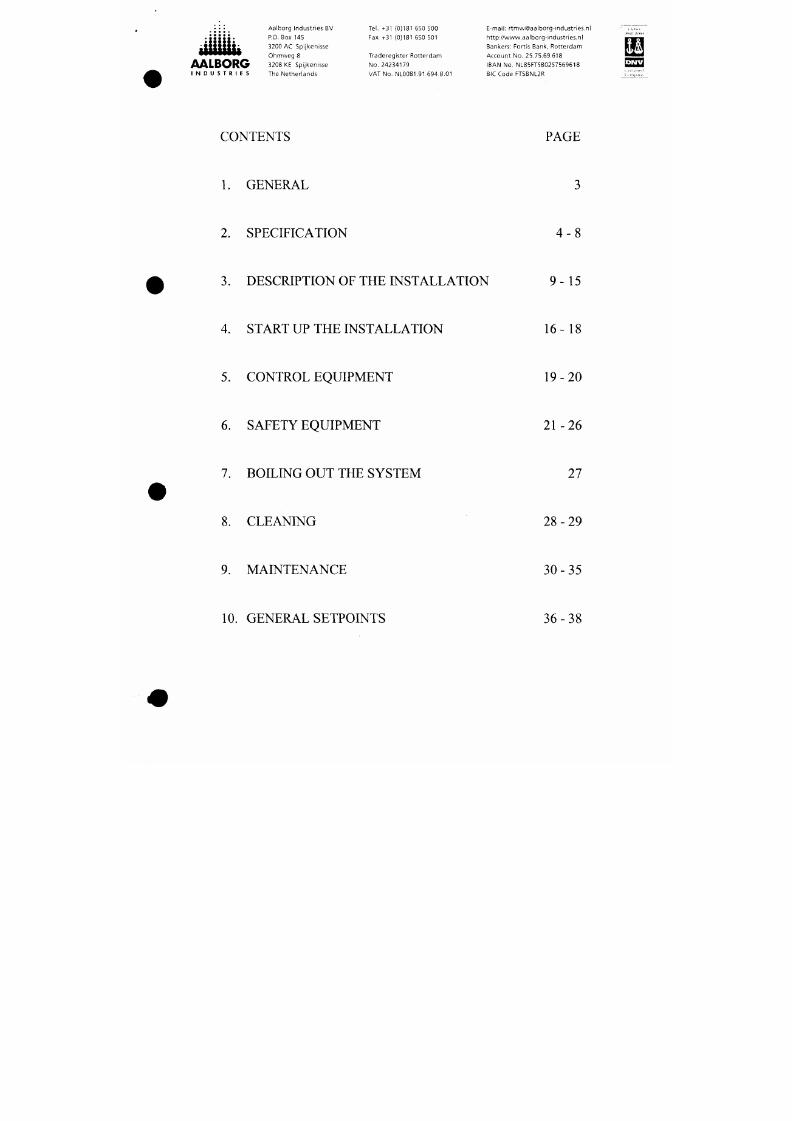
CONTENTS PAGE
L GENERAL
2.
SPECIFICATION
4 - 8
3.
DESCRIPTION OF THE INSTALLATION 9 - 1 5
4. START UP THE INSTALLATION 1 6 -1 8
5.
CONTROL EQUIPMEN T
1 9 - 2 0
7/18/2019 M14 Thermal Fluid
http://slidepdf.com/reader/full/m14-thermal-fluid 4/486
AALBORG
I N D U S T R I E S
Aalborg Industr ies BV
P.O. Box 145
3200 AC Spijkenisse
Ohm weg 8
3208 KE Spijkenisse
The Netherlands
Tel. +31 (0)181 650 500
Fax +31 (0)181 650 501
Traderegister Rotterdam
No. 24234179
VAT No. NL0081.91.694.8.01
E-mail: r tmw@aalborg-industr ies.nl
h t tp : / /www.aalborgHndus t r ies .n l
Bankers: Fort is Bank, R otterda m
Account No. 25.75.69.618
IBAN No. NL85FTSB0257559618
BIC Code FTSBNL2R
^^3
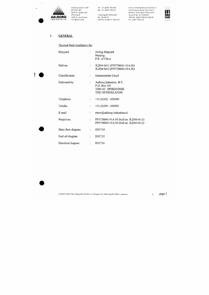
G E N E R A L
Thermal fluid installation for:
Shipyard
Hull no.
Classification
Delivered by
Telephone
Jinling Shipyard
Nanjing
P.R. of China
JLZ04-0411 (PP5738841-01A.00)
JLZ04-0412 (PP5738842-01A.00)
Germanischer Lloyd
Aalborg hidustries B.V.
P.O.
Box 145
3200 AC SPIJKENISSE
THE NETHERLANDS
+31 (0)181-650500
7/18/2019 M14 Thermal Fluid
http://slidepdf.com/reader/full/m14-thermal-fluid 5/486
AALBORG
I N D U S T R I E S
Aalborg Industr ies BV
P.O. Box 145
3200 AC Spijkenisse
Ohrnweg 8
3208 KE Spijkenisse
The Netherlands
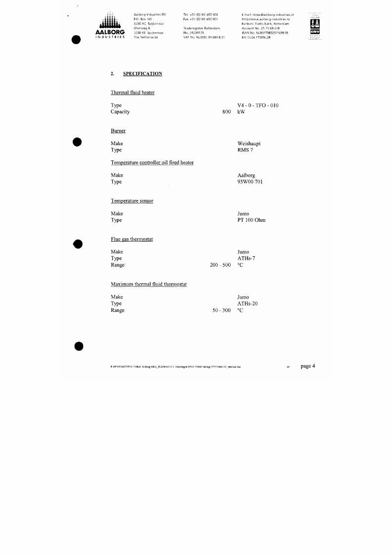
SPECIFICATION
Thermal fluid heater
Tel. +31 (0)181 650 500
Fax +31 (0)181 650 501
Traderegister Rotterdam
No. 24234179
VAT No. NL0081.91,694.B.01
E-mail: r tmw@aalborg- indus t r ies .n l
h t tp : / /www,aa lborg-industr ies.nl
Bankers: Fortis Bank, Rotterdam
Account No. 25.75.69.618
IBAN No . NL85FTSB0257569618
BIC Code FTSBNL2R
Type
Capacity
V 4 - 0 - T F O - 0 1 0
800 kW
Burner
Make
Type
Weishaupt
R M S 7
Tem perature controller oil fired heater
Make
Type
Aalborg
93 WOO 701
7/18/2019 M14 Thermal Fluid
http://slidepdf.com/reader/full/m14-thermal-fluid 6/486
AALBORG
I N D U S T R I E S
Aalborg Industr ies BV
P-O. Box 145
3200 AC Spijkenisse
Ohmvveg 8
3208 KE Spijkenisse
The Netherlands
Tel. +31 (0)181 650 500
Fax +31 (0)181 650 501
Traderegister Rotterdam
No. 24234179
VAT No. NL 0081.91.694.B.01
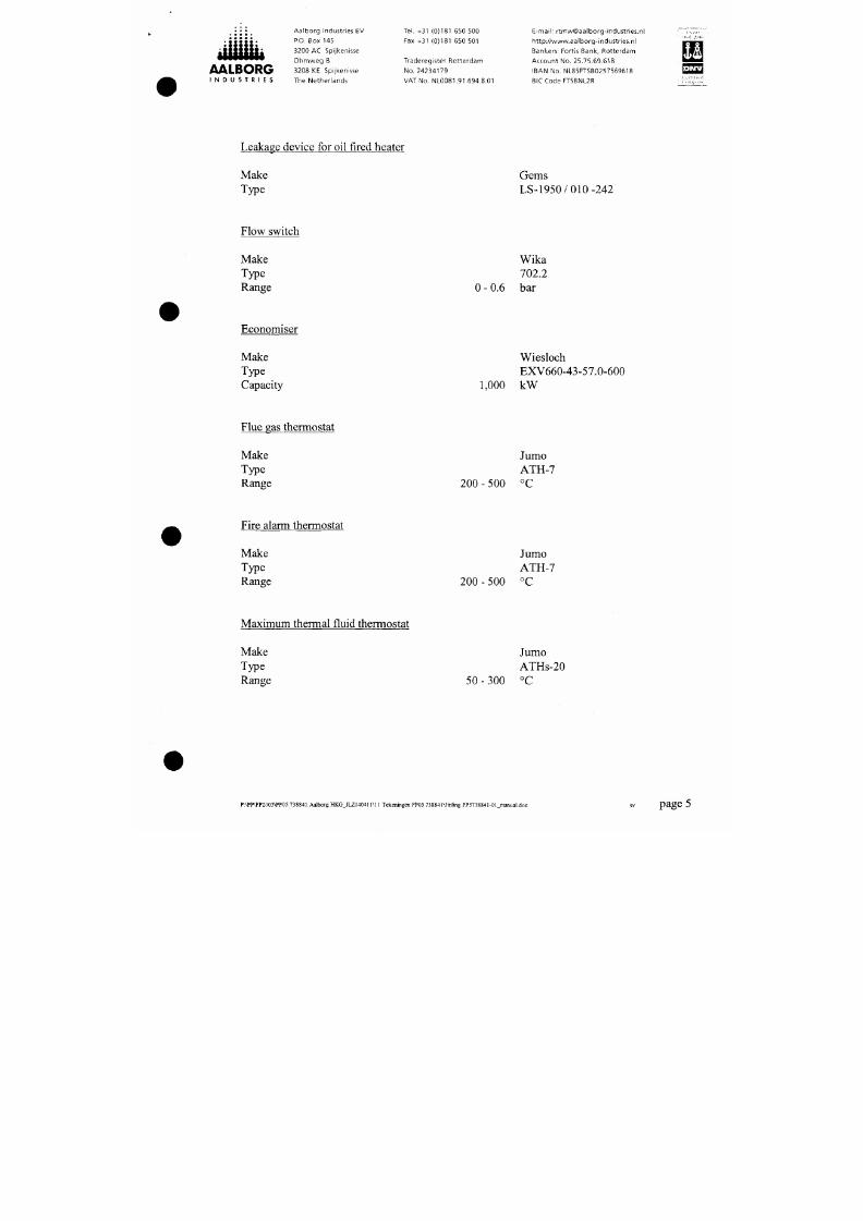
Leakage device for oil fired heater
E-mail: r tmw@aalborg-industr ies.nl
ht tp: / /www.aalborg-industr ies.nl
Bankers: Fortis Bank, Rotterdam
Account No. 25,75.69.618
IBAN N o. NL85FTSB0257569618
BIC Code FT5BNL2R
Make
Type
Gems
LS-1950 /010-242
Flow switch
Make
Type
Range
Wika
702.2
0 - 0.6 ba r
Economiser
Make
Type
Capacity
Wiesloch
EXV660-43-57.0-600
1,000 kW
7/18/2019 M14 Thermal Fluid
http://slidepdf.com/reader/full/m14-thermal-fluid 7/486
AALBORG
I N D U S T R I E S
Aalborg Industr ies BV
P.O. Box 145
3200 AC Spijkenisse
Ohm w eg 8
3208 KE Spijkenisse
The Netherlands
Tel. +31 (0)181 650 500
Fax +31 (0)181 650 501
Traderegister Rotterdam
No.
24234179
VAT No. NL0081.91.594.B.01
E-mail: r tmw@aalborg-industr ies.nl
ht tp: / /www.aalborg-industr ies.ni
Bankers: Fortis Bank, Rotterdam
Account No. 25.75.59.618
IBAN No. NL85FTSB0257569618
BICCode FTSBNL2R
E ^
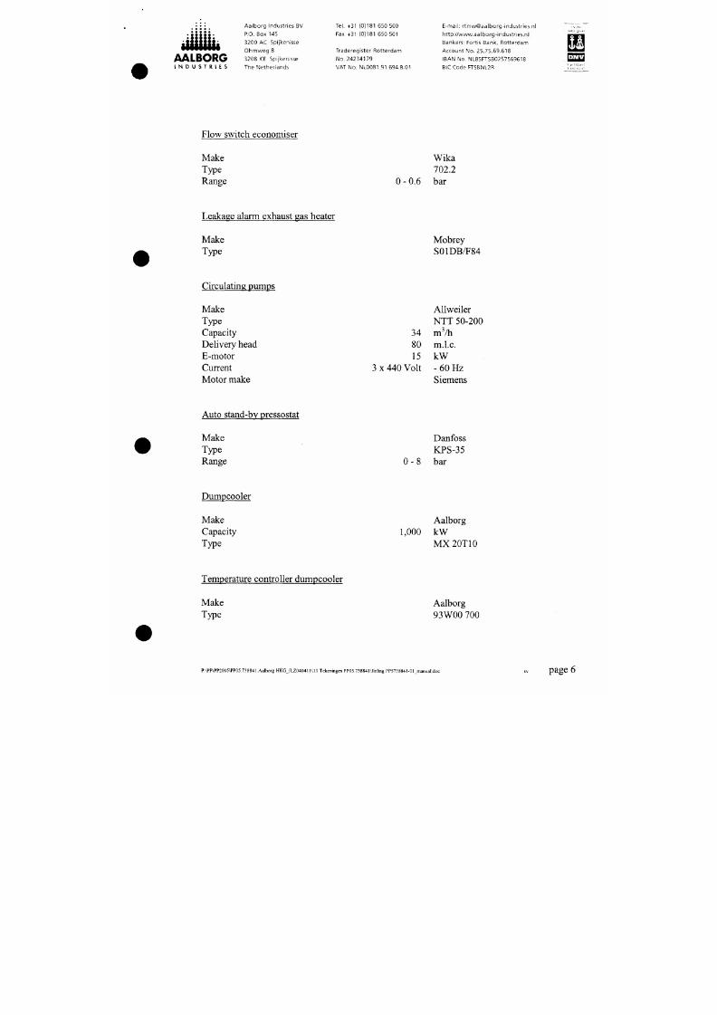
Flow switch economiser
Make
Type
Range
Wika
702.2
O
- 0.6 bar
Leakage alarm exhaust gas heater
Make
Type
Mobrey
S01DB/T84
Circulating pumps
Make
Type
Capacity
Delivery head
34
Allweiler
NTT 50-200
m^/h
m.l.c.
7/18/2019 M14 Thermal Fluid
http://slidepdf.com/reader/full/m14-thermal-fluid 8/486
• • • • •
AALBORG
I N D U S T R I E S
Aalborg Industr ies BV
P.O. Box 145
3200 AC Spijkenisse
Ohmweg 8
3208 KE Spijkenisse
The Netherlands
Tel. +31 (0)181 650 500
Fax +31 (0)181 550 501
Traderegister Rotterdam
No.
24234179
VAT No. NL0081.91.694.B.01
E-mail: r tmw@aalborg-industr ies.nl
ht tp; / /www.aalborg- indus t r ies .n l
Bankers: Fortis Bank, Rotterdam
Account No, 25.75.69.618
IBAN No. NL85FTSB0257569618
BICCode FTSBNL2R
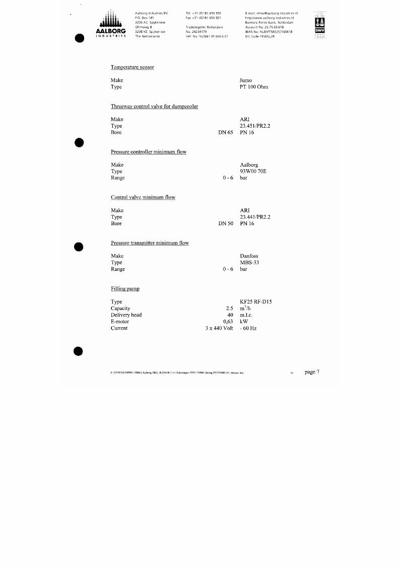
Temperature sensor
Make
Type
Jumo
PT 100 Ohm
Threeway control valve for dum pcooler
Make
Type
Bore
D N 6 5
ARI
23.451/PR2.2
PN 16
Pressure controller minimum flow
Make
Type
Range
Aalborg
93W00 70E
0-6 bar
7/18/2019 M14 Thermal Fluid
http://slidepdf.com/reader/full/m14-thermal-fluid 9/486
AALBORG
I N D U S T R I E S
A a l b o r g I n d u s t r i e s B V
P.O. Box 145
3200 AC Sp i j ken i sse
Ohmweg 8
3208 KE S p i j ken i sse
T h e N e t h e r l a n d s
Te l .
+31 (0 )181 650 500
Fax +31 (0)181 550 501
T r a d e r e g i s t e r R o t t e r d a m
N o . 2 4 2 3 4 1 7 9
VAT No . NL0081 .91 .694 .B .01
E - m a i l : r t m w @ a a i b o r g - i n d u s t r i e s . n l
h t t p : / / w w w . a a l b o r g - i n d u s t r i e s . n l
B a n k e r s : F o r t i s B a n k , R o t t e r d a m
A c c o u n t N o . 2 5 . 7 5 . 6 9 . 6 1 8
I B A N N o . N L 8 5 F T 5 B 0 2 5 7 5 6 9 6 1 8
BIC Code FTSBNL2R
22H
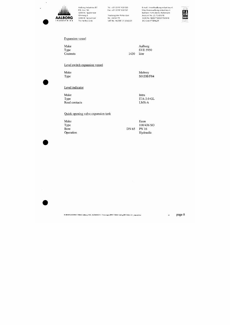
Expansion vessel
Make
Type
Contents
Aalborg
SVE 5950
1430 liter
Level switch expansion vessel
Make
Type
Mobrey
S01DB/F84
Level indicator
Make
Type
Reed contacts
Intra
ITA-3.0-GL
LMS-A
7/18/2019 M14 Thermal Fluid
http://slidepdf.com/reader/full/m14-thermal-fluid 10/486
• • • •
•
: S S S S S :
iiuuiiå
AALBORG
I N D U S T R I E S
Aalborg Industries BV
P.O. Box 145
3200 AC Spijkenisse
Ohmweg 8
3208 KE Spijkenisse
The Netherlands
Tel. +31 (0)181 650 500
Fax +31 (0)181 650 501
Traderegister Rotterdam
No .
24234179
VAT No. NL0081.91.694.8,01
E-mail: r tmw@aalborg- indust r ies .nl
ht tp: / /www.aalborg- indust r ies .nl
Bankers: Fort is Bank, Ro tterdam
Account No. 25.75.69.618
IBAN No. NL85FTSB0257569618
BIC Code FTSBNL2R
[^^
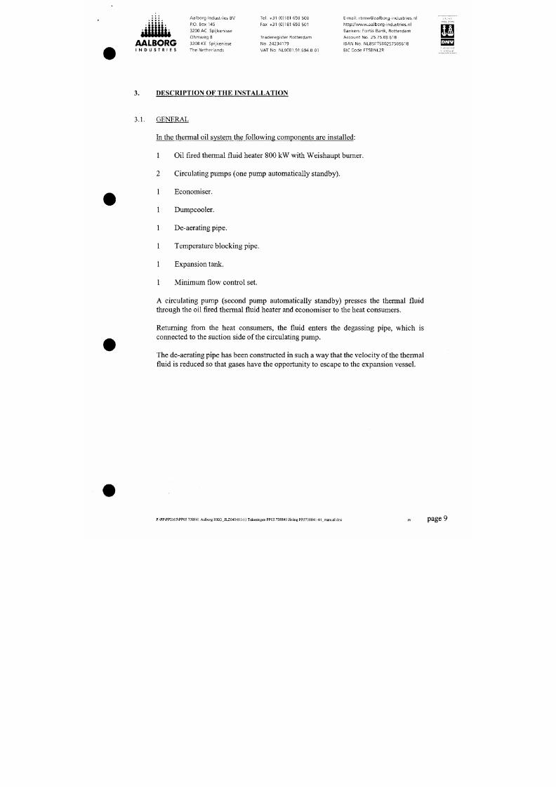
3.
DESCRIPTION O F THE INSTALLATION
3.1. GENERAL
In the thermal oil system the following components are installed:
1 Oil fired thermal fluid heater 800 kW with W eishau pt bum er.
2 Circulating pum ps (one pum p automatically standby).
Economiser.
Dumpcooler.
De-aerating pipe.
Temperature block ing pipe.
Expansion tank.
7/18/2019 M14 Thermal Fluid
http://slidepdf.com/reader/full/m14-thermal-fluid 11/486
AALBORG
I N D U S T R I E S
Aalborg Industr ies BV
P.O. Box 145
3200 AC Spijkenisse
Ohmweg 8
3208 KE Spijkenisse
The Netherlands
Tel. +31 (0)181 650 500
Fax +31 (0)181 650 501
Traderegister Rotterdam
No. 24234179
VAT No. NL0081.91.694.B.01
Em a i l : r tmw@aalborgHndustr ies.nl
ht tp: / /www.aalborg-industr ies.nl
Bankers: Fortis Bank, Rotterdam
Account No. 25.75.69.618
IBAN No. NL85FTSB0257569618
BIC C ode FTSBNL2R
^ 3
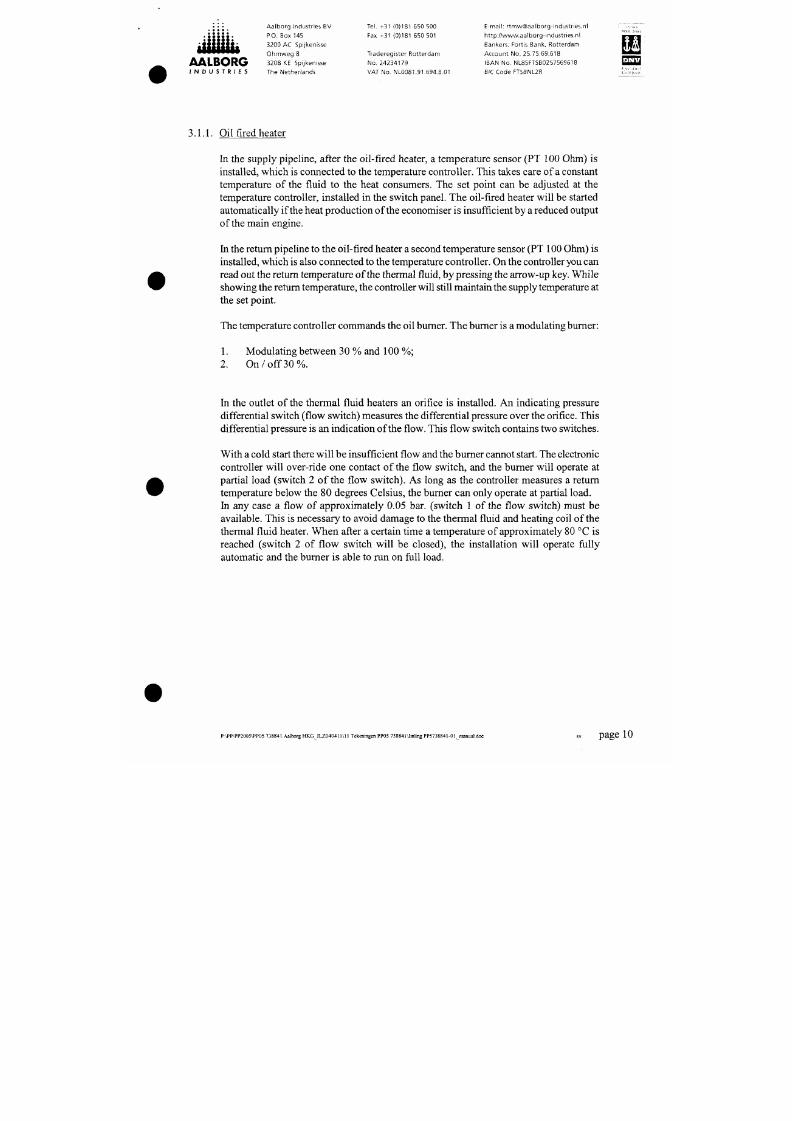
3.1.1.
Oil fired heater
In the supply pipeline, after the oil-fired heater, a temperature sensor (PT 100 Ohm) is
installed, which is connected to the temperature controller. This takes care of a constant
temperature of the fluid to the heat consumers. The set point can be adjusted at the
temperature controller, installed in the switch panel. The oil-fired heater will be started
autom atically if the heat production of the economiser is insufficient by
a
reduced o utput
of the main engine.
In the return pipeline to the oil-fired h eater a second temperatu re sensor (PT 100 Ohm ) is
installed, which is also connec ted to the tempe rature con troller. On the controller you can
read out the return tempe rature of the therm al fluid, by pressing the arrow-up key. While
showing the return tem pera ture, the controller will still maintain
the
supply temperature at
the set point.
The temperature controller com mands the oil burner. The burner is a modulating burner:
1.
Modulating betwe en 30 % and 100 %;
2. O n / o f f
30%.
7/18/2019 M14 Thermal Fluid
http://slidepdf.com/reader/full/m14-thermal-fluid 12/486
Aa lbo rg Industries BV Tel. +31 (0)181 650 500 E-mail: r tmw@aalborg-indu5tr ies.nl iTTCi
P.O. Box 145 Fax +31 (0)181 650 501 http ;// www.aalborg- indus t r ies .n l nrm
3200 AC Spijkenisse Bankers: Fortis Bank, Rotterd am P jØ ^^
Oh mw eg 8 Traderegister Rotterda m Account No. 25.75.69.618 i S S S l
A A L B O R G 3208 KE Spijkenisse No. 24234 179 IBAN No. NL85FTSB0257559618 ^ ^ Q
I N D U S T R I E S The Ne ther land s VAT No. NL008 1.91.694.B.01 BIC Code FTSBNL2R
"^"^"t
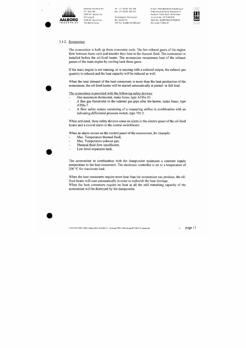
3.1.2. Economiser
The economiser is built up from concentric coils. The hot exhaust gases of the engine
flow between these coils and transfer their heat to the thermal fluid. The economiser is
installed before the oil-fired heater. The economiser recuperates heat of the exhaust
gasses of the main engine by cooling back these gases.
If the main engine is not running, or is running with a reduced output, the exhaust gas
quantity is reduced and the heat capacity will be reduced a s well.
When the heat demand of the heat consumers is more than the heat production of the
economiser, the oil-fired heater will be started automatically at partial- or full load.
The economiser is provided w ith the following safety de vices:
One maximum thermostat, make Jum o, type ATH s-20.
A flue gas thermostat in the exhaust gas pipe after the heater, make Jumo, type
ATHs-7.
A flow safety system consisting of a measuring orifice in combination with an
indicating differential pressure switch, type 702-2.
7/18/2019 M14 Thermal Fluid
http://slidepdf.com/reader/full/m14-thermal-fluid 13/486
.
:i i.
• •
• • •
:S t tS S :
iiiiiiiji
AALBORG
I N D U S T R I E S
Aalborg Industr ies BV
P.O. Box 145
3200 AC Spijkenisse
Ohmweg 8
3208 KE Spijkenisse
The Netherlands
Tel. +31 (0)181 550 500
Fax +31 (0)181 650 501
Traderegister Rotterdam
No. 24234179
VAT No. NL0081.91.594.B.01
E-mail; r tmw@aalborg-industr ies.nl
h t tp : / /www.aalborg- indus t r ies .n l
Bankers: Fortis Bank, Rotterdam
Account No. 25.75.69.618
IBAN No. NL85FT5B0257569618
BICCode FTSBNL2R
As with the oil-fired heater, the minimum quantity of thermal fluid flowing through the
heater tubes must be maintained in order to prevent cracking of the thermal fluid and
damag ing the heater tubes. During port operation th e econom iser has to circulate as well.
This is to prevent dew point corrosion.
The econom iser is provided with cleaning nozz les, which are installed in
the
bottom part
and connected to the w ater system of the ship.
During operation the valves before the nozzles can be opened and the heater will be
cleaned. To keep the heat surface of the econom iser clean, it is advisable to open these
valves once a week, during 20 - 30 sec. with intervals of approx. 15 minutes until the
economiser is clean.
The bottom of the thermal fluid heater is provided with a drain connection, which is
connected
to
a float chamber with a level switch (leakage device). If there is
a
leakage the
level switch will give an alarm on th e control panel of the thermal fluid system.
Furthermore the economiser is provided with extinguish nozzles. These nozzles can be
opened at a safe plac e and are able to cool the heating surface during 30 m inutes.
The se nozzles are only to be used in case of a fire.
u
223
7/18/2019 M14 Thermal Fluid
http://slidepdf.com/reader/full/m14-thermal-fluid 14/486
. ; i ; .
• • • • •
iflliijii
AALBORG
I N D U S T R I E S
Aalborg Industries BV
P.O. Box 145
3200 AC Spijkenisse
Ohmweg 8
3208 KE Spijkenisse
The Netherlands
Tel. +31 (0)181 550 500
Fax +31 (0)181 650 501
Traderegister Rotterdam
No .
24234179
VAT No. NL0081.91.694.B.01
E-mail: [email protected]
ht tp: / /www.aalborg- indust r ies .nl
Bankers: Fortis Bank, Rotterd am
Accou nt No. 25.75.69.618
IBAN No. NL85FTSB0257569618
BIC Code FTSBNL2R
^ ^
3.1.3. Dumpcooler
After the oil-fired heater, a dump cooler is installed. It is made of steel so the cooling
water can only be closed fresh water. A dumpcooler is necessary when the heat
production of the economiser is m ore than the heat demand of the heat consumers.
An electronic temperature c ontroller will activate an electric three-way
valve,
depending
on the temperature and the (partial) flow will pass through the dumpcooler.
After passing the cooler the thermal fluid is directed to the heat consumers.
IMPORTANT:
Do not close the valves on the waterside.
3.1.4. M inim um flow control set
As mentioned before the oil-fired thermal fluid heater and econom iser are equipped with
flow switches. The system must guarantee sufficient flow.
7/18/2019 M14 Thermal Fluid
http://slidepdf.com/reader/full/m14-thermal-fluid 15/486
Ill
«
• • •
:tittt:
ittsiiib
AALBORG
I N D U S T R I E S
Aalborg Industries BV
P.O. Box 145
3200 AC Spijkenisse
Ohmweg 8
3208 KE Spijkenisse
The Netherlands
Tel. +31 (0)181 650 500
Fax +31 (0)181 650 501
Traderegister Rotterdam
No.24234179
VAT No. NL0081.91.694.B.01
E-mail: r tmw@aalborg-industr ies.nl
ht tp: / /www.aalborg-industr ies.nl
Bankers: Fortis Bank, Rotterdam
Account No. 25.75.59.618
IBAN No. NL85FTSB0257569618
BIC Code FTSBNL2R
rrr .,
F S H
im
' ',;,. |; ^ '
3.1.5.
De-aeration pipe
The return line of the heat consum ers is connected with the d e-aerating pipe. The bottom
side of this pipe is connected to the suction side of the circulating pumps. During the
operation of the installation, light fractions or vapours can develop. To give these gases
the opportunity to escape via the expansion tank to the atmosphere, the velocity of the
fluid is reduced in the de-aeration p ipe, the top of wh ich is connected with the top of the
expansion tank.
The de-aerating pipe gives the possibility of a continuous de-aeration.
Ano ther pipe is the expansion pipe ; it is connected to the bottom of the exp ansion tank.
This pipeline gives the thermal fluid the opp ortunity to increase and decrease in vo lume
caused by tem perature differences.
3.1.6. Temperature blocking pipe
The lifetime of thermal fluid can be greatly reduced if the thermal fluid is in contact with
oxygen (air) by high temperature.
7/18/2019 M14 Thermal Fluid
http://slidepdf.com/reader/full/m14-thermal-fluid 16/486
AALBORG
I N D U S T R I E S
Aalborg Industr ies BV
P.O. Box 145
3200 AC Spijkenisse
Ohmvveg 8
3208 KE Spijkenisse
Tlie Netherlands
Tel. +31 {0)181 650 500
Fax +31 {0)181 650 501
Traderegister Rotterdam
No .
24234179
VAT No. NL0081,91.694.B.01
E-mail: r tmw@aalborg-industr ies.nl
h t tp : / /www.aalborg- indus t r ie5.n l
Bankers: Fortis Bank, Rotterdam
Account No. 25.75.69.618
IBAN No. NL8SFTSB0257569618
BIC Code FTSBNL2R
t M , . .
i n
Im
T?P]
; ' : ; ' , ; ' ; ; , v
IMPORTANT:
It is very important to keep the expansion tanks as cool as possible because the
quality of the thermal fluid will reduce greatly if the fluid is in contact with oxygen
(air) by high temperature. Therefore be sure that the temperature does not rise
above app roximately 70 °C. To ensure this a high temp erature alarm is installed.
3.1.8. Boiling out pipe
Most light
fi-actions
and vapours will develop by heating the fluid during the first start up.
Furthermore it can happen that some water is in the installation, which w ill evaporate in
the heater. To give the steam and light gases the opportunity to leave the installation as
soon as possible, a boiling out pipe is mounted directly behind the heater on the de-
aerator. This boiling out pipe is provided with a valve, which is connected to the top of
the expansion tank.
IMPORTANT:
It is only allowed to open the boiling out valve during the first start up period, until
all the gases have escaped to the atmospher e.
7/18/2019 M14 Thermal Fluid
http://slidepdf.com/reader/full/m14-thermal-fluid 17/486
AALBORG
I N D U S T R I E S
Aalborg Industr ies 6V
P.O. Box 145
3200 AC Spijkenisse
Ohmweg 8
3208 KE Spijkenisse
The Netherlands
Tel. +31 (0)181 650 500
Fax +31 (0)181 650 501
Traderegister Rotterdam
No.
24234179
VAT No. NL0081.91.694.B.01
E-mail: r tmw@aalborg-industr ies.nl
h t tp : //www.aalborg- indus t r ies .n l
Bankers: Fortis Bank, Rotterda m
Account No. 25.75.69.618
IBAN No. NL85FTSB0257569618
BIC Code FTSBNL2R
I N ; M / ^
WIFM
W i
[ ^ > : - ^ - ^ , - - l
START LP THE INSTALLATION
4.1. GENERAL:
1. Main switch in position "O N "
2. Start one of the thermal fluid circulating pum ps of the oil fired heater and
economiser.
Check flow over oil fired h eaters and eco nomiser.
3.
Start fuel oil supply pum ps
4. Adjust temperature on temperature controller of oil-fired heater.
5.A. For W eishaupt burner
5.A. 1 Place switch "BURNER ON/O FF" in position "ON".
7/18/2019 M14 Thermal Fluid
http://slidepdf.com/reader/full/m14-thermal-fluid 18/486
AALBORG
I N D U S T R I E S
Aalborg Industr ies BV
P.O. Box 145
3200 AC Spijkenisse
Ohmweg 8
3208 KE Spijkenisse
The Netherlands
Tel. +31 (0)181 650 500
Fax +31 (0)181 650 501
Traderegister Rotterdam
No . 24234179
VAT No. NL0081.91.694.B.01
E-mail: r tmw@aalborg-industr ies.nl
ht tp: / /wvvw,aalborg-industr ies.nl
Bankers: Fortis Bank, Rotterdam
Account No. 25.75.69.618
IBAN No. NL85FTSB0257569618
BIC Code FTSBNL2R
4.2. FUEL OIL OPERATION
General:
The system is able to handle and to b um heavy fiiel oil w ith a viscosity of 380 cSt at
50 °C.
For the first start-up and also if the therm al fluid installatio n has been o ut of operation for
a longer period of
time,
M.D .O. has to be used.
Before starting the burner, be sure that a fuel pu mp is running. You can start the burner as
described earlier.
If you wan t to operate on H .F.O., be sure that the fuel oil in the service tank is between
70-80°C and that the tracing of the H.F.O.-pipelines for the thermal fluid is in operation.
The H.F .O. will now circulate from the H.F.O. service tank to the ga s-air separator over a
pressure reh ef valve. T he pressure relief valve will adjust at a set point of 2,5 - 3 bar(g),
the pressure can be read out on the pressure gauge, moun ted before th e relief valve.
7/18/2019 M14 Thermal Fluid
http://slidepdf.com/reader/full/m14-thermal-fluid 19/486
•
•
• •
>
« • • • «
iijiiiiii
AALBORG
I N D U S T R I E S
Aalborg Industries BV
P.O. Box 145
3200 AC Spijkenisse
Ohmweg 8
3208 KE Spijkenisse
The Nether lands
Tel.
+31 (0)181 550 500
Fax +31 (0)181 650 501
Traderegister Rotterdam
No .
24234179
VAT No. NL0081.91.694.B.01
E-mail: [email protected]
ht tp: / /www.aalborg- indust r ies .nl
Bankers: Fortis Bank, Rotterd am
Accoun t No. 25.75.69.618
IBAN No. NL85FT5B0257569618
BIC Code FTSBNL2R
^ ^
It can happe n that after th e change over proced ure the burn er stops. Reason for this is that
the heavy fuel oil temperature at the burn er is too low . This situation will be shown on the
electric panel. After a few m inutes the temperature is sufficient and the burner re-starts
automatically.
Furthermore the fuel pre-heater is provided with a maximum thermostat for fuel oil. If
this thermostat is activated, the burner will be blocked electrically and has to be reset.
CHANGE OVER FROM H.F.O. TO M.D.O.
When chang ing back to M .D.O., you manu ally activate the change over valves slowly
during operation of the burner.
When switching back, activate valve 1.After a few minutes activate valve 2.
This is necessary to avoid that H.F.O . will enter the M.D .O. service tank. Then you
activate the switch "M.D.O. - H.F.O." back in position M.D.O.
7/18/2019 M14 Thermal Fluid
http://slidepdf.com/reader/full/m14-thermal-fluid 20/486
• • • • •
« • •
•
•
üttüsii
AALBORG
I N D U S T R I E S
Aalbo rg Industr ies BV
P.O. Box 145
3200 AC Spijkenisse
Ohmweg 8
3208 KE Spijkenisse
The Netherlands
Tel. +31 (0)181 650 500
Fax +31 (0)181 650 501
Traderegister Rotterdam
No .
24234179
VAT No. NL0081.91.694.B.01
E-mail ; r tmwQaalborg-industr ies.n
http: / /www.aalborg-industr ies.nl
Bankers: Fortis Bank, Rotterdam
Account No. 25.75.69.618
IBAN No. NL85FTSB0257569618
SIC Code FTSBNL2R
^33
5.
CONTROL EQUIPMENT
5.1.
OIL FIRED HEATER
Temperature controller
The set point of the temperature controller can be adjusted by pressing the "P " button (see
also instruction book temperature co ntroller). As a temperature sensor a PT 100 Ohm is
connected to the controller.
By pressing the "P" button you can read out this set point. After releasing the press
button, the measured temperature to the heat consum ers will be shown on the display.
After adjusting the correct supply temperature, the burner is allowed to start.
The burner w ill start fully automatic according to the following procedu re:
Be s ure that one o f the fiiel oil transfer pumps is in operation.
Fan a nd fuel oil pum p will be started.
7/18/2019 M14 Thermal Fluid
http://slidepdf.com/reader/full/m14-thermal-fluid 21/486
Aa lb or g Industries BV Tel. +31 (0)181 650 500 E-mail: r tmw@aalborgHndust r ies .nl " 7 ^ . " ^
P.O. Box 145 Fax +31 (0)181 650 501 http ;//www.aalborg- indust r ies .nl '^mrm
3200 AC Spijkenisse Bankers: Fortis Bank, Ro tterd am fiff'^
Oh mw eg 8 Traderegister Rotterda m Account No. 25.75.69.618 S i S l
A A L B O R G 3208 KE Spijkenisse No. 24234179 IBAN No. NL85FTSB0257559618 ^ ^
I N D U S T R I E S The Neth erlan ds VAT No. NL0081 .91.694.B.01 BiC Code FTSBNL2R
The temperature controller is provided with two switches. When there is a large heat
demand the second switch will be closed and the burner will operate at full load. If the
heat demand is reduced the burner modulates automatically back to partial load.
If the heat prod uction of the econo mizer is high enough the burner will be switched off
In the return lin e of the oil fired heater a second PT 100 Ohm sensor is installed, which is
also connected to the temperature controller. By means of a push-button (see the
description of the controller) you are able to read out the inlet temperature of the thermal
fluid into the oil fired heater. While showing the return temperature, the controller will
maintain the supply temperature at the set point.
5.2. DUMPCOOLER
When there is an overproduction of heat by the econo mizer, the supply temperature will
be controlled by a temperature controller in combination with a three-way valve. The
three-way va lve m ixes the un-cooled th erm al fluid with the thermal fluid that is cooled by
the Dum pcooler to the required supply temp erature.
The three-way valve is controlled by a stop controller with a P + I action.
7/18/2019 M14 Thermal Fluid
http://slidepdf.com/reader/full/m14-thermal-fluid 22/486
AALBORG
I N D U S T R I E S
Aalborg Industr ies BV
P.O. Box 145
3200 AC Spijkenisse
Ohm w eg 8
3208 KE Spijkenisse
The Netherlands
Tel. +31 (0)181 650 500
Fax +31 (0)181 650 501
Traderegister Rotterdam
No . 24234179
VAT No. NL0081.91.694.B.01
E-mail: r tmw@aalborg-industr ies.nl
ht tp: / /www.aalborg-indu5tr ies.nl
Bankers: Fortis Bank, Rotterdam
Account No. 25.75.69.618
IBAN No. NL85FTSB0257569618
BIC Code FTSBNL2R
[233
6. SAFETY EQUIPM ENT
IMPORTANT: IT IS NEVER ALLOWED TO OVERRULE THE SAFETY DEVICES
6.1.
OIL FIRED HEATER
6.1.1. Minimum flow switch
In the outlet of the oil fired heater an orifice is installed. With a pressure differential
switch the flow will be registered. The larger the flow, the larger the pressure drop is at
the pressure differential switch.
The pressure differential switch is provided with two contacts. After starting the
circulating pump the first contact has to be closed and is adjusted at 0.05 bar.
The flow switch will give an indication of approx. 0.4 bar pressure difference through the
installed orifice. During normal circumstances the indication of the pressure differential
switch is 0.4 bar. The secon d contact is adjusted at approx. 0.25 bar.
7/18/2019 M14 Thermal Fluid
http://slidepdf.com/reader/full/m14-thermal-fluid 23/486
Aa lbo rg Industries BV Tel. +31 (0)181 650 500 E-mail: r tmw@aalborg-industr ies.nl
P.O. Box 145 Fax +31 (0)181 550 501 ht tp: / /www.aalborg-industr ies.nl
3200 AC Spijkenisse Bankers: Fortis Bank, Rotte rdam
Oh mw eg 8 Traderegister Rotterd am Account No. 25.75.69,618 mmmm
L ORG 3208 KE Spijkenisse No. 2423417 9 IBAN No. NL85FTSB0257569618 E ^ l
I N D U S T R I E S The Nethe rlands VAT No. NL0081.91.694.E.01 BIC Code FTSBNL2R I:,':;";"™
6.1.2. Maximum temperature of thermal fluid
ha the supply line of the oil-fired heater a maximum fluid thermostat is installed.
The adjusted value w ill be approx. 20 °C (or ±10 % ) above the operation temperature.
Check if this temp erature is not above the allow ed m aximum bulk temp erature according
to the instructions of the supplier of the thermal fluid.
If this thermostat is activated, the burner will be stopped and electrically b locked.
6.1.3. Maximum flue gas thermostat
In the flue gas connection of the oil-fired heater a m aximum thermostat is installed. This
thermostat has to b e adjusted at a set point 10 % higher than the flue gas temperatu re at
fiill load of the burner, at the temperature of the thermal fluid during operation.
If this temperature is exceeded the burner will switch off and block electrically.
For a good adjustment of the thermostat adjust it above the measured temperature, and
turn it back very slowly with several time intervals. At a certain m oment the b urner trips,
7/18/2019 M14 Thermal Fluid
http://slidepdf.com/reader/full/m14-thermal-fluid 24/486
• • • • •
• • • • •
;ssstS:
«ttüüi*
AALBORG
I N D U S T R I E S
Aalborg Industr ies BV
P.O. Box 145
3200 AC Spijkenisse
Ohmweg 8
3208 KE Spijkenisse
The Netherlands
Tel. +31 (0)181 650 500
Fax +31 (0)181 650 501
Traderegister Rotterdam
No. 24234179
VAT No. NL0081.91.694.B.01
E-mail: r tmw@aalborg-industr ies.nl
h t tp : / /www.aalborg- indus t r ies .n l
Bankers: Fortis Bank, Rotterdam
Account No. 25.75.69.618
IBAN No. NL85FT5B0257569618
SIC Code FT5BNL2R
2^3
6.2. ECONOMISER
6.2.1. Flow switch
The flow alarm switc h will give an indication of ap prox. 0.4 bar pressu re difference over
the installed orifice. If the pressu re difference (= flow) is too low, an alarm in the ECR is
generated.
The alarm is adjusted at approx. 0.25 bar.
6.2.2. Maxim um temperature of thermal fluid
The economiser is provided with
a
maximum thermal fluid thermostat (ATH-SE-20). The
set point of the thermostat is approx. 2 0 "C higher than the maximum operating tempera
ture. If this thermostat is activated, only an alarm in the EC R is generated.
6.2.3.
Maxim um exhaust gas thermostat
7/18/2019 M14 Thermal Fluid
http://slidepdf.com/reader/full/m14-thermal-fluid 25/486
AALBORG
I N D U S T R I E S
Aalborg Industr ies BV
P.O. Box 145
3200 AC Spijkenisse
Ohmweg 8
3208 KE Spijkenisse
Tiie Netherlands
Tel. +31 (0)181 650 500
Fax +31 (0)181 650 501
Traderegister Rotterdam
No .
24234179
VAT No. NL0081.91.694.B.01
E-mail: r tmw@aalborg- indus t r ies .n l
h t tp : / /www.aalborg- indus t r ies .n l
Bankers: Fort is Bank, Ro tterdam
Account No. 25.75.69.618
IBAN No. NL85FTSB0257569618
BIC Code FTSBNL2R
^ ^
6.2.4.
Fire alarm
A second flue gas therm ostat is installed and has a higher set point. This thermostat is
activated in case of a fire in the economiser.
If there is a
fire
n the econom iser, the valves for the extinguish nozzles
have to
be opened
and the fire fighting pum p has to be started.
The main engine has to be reduced to 50 % of the ou tput.
Note:
Before resetting the failure on the alarm panel of the ECR, first reset the thermo
stat itself (with the reset-button).
6.2.5.
Leakage device
If there is a leakage in the economiser, a floating switch is activated and will stop the
burner. To empty the float chamber the valve under the float chamber should be open ed.
On top of the floating chamber of the leakage device a second valve is mounted. Through
7/18/2019 M14 Thermal Fluid
http://slidepdf.com/reader/full/m14-thermal-fluid 26/486
AALBORG
I N D U S T R I E S
Aalbo rg Industr ies BV
P.O. Box 145
3200 AC Spijkenisse
Ohmweg 8
3208 KE Spijkenisse
The Netherlands
Tel. +31 (0)181 650 500
Fax +31 (0)181 550 501
Traderegister Rotterdam
No.
24234179
VAT No. NL0081.91.694.B.01
E-mail: r tmw@aalborg-industr ies.nl
ht tp: / /www.aalborg-industr ies.nl
Bankers: Fortis Bank, Rotterdam
Account No. 25.75.69.618
IBAN No. NL85FTSB0257569618
BIC Code FTSBNL2R
[ 3 2 3 3
6.3. EXPANSION TANK
On the expansion tank following level switches are mou nted:
6.3.1.
Low low level
This level switch is mo unted on the tank and after en ergizing the switch the circulating
pumps and b urner will be switched off. The level switch will be electrically blocked.
6.3.2. Low level
This level sw itch (reed contact) is adjustable and moun ted on the level indicator.
The adjustable alarm has to be adjusted in such a way that by a normal op eration the level
switch is just below the level in the expansion tank.
The alarm h as a time delay to avoid alarms due to rolling of the ship.
Alarm can be caused by:
7/18/2019 M14 Thermal Fluid
http://slidepdf.com/reader/full/m14-thermal-fluid 27/486
AALBORG
I N D U S T R I E S
Aalb org Industr ies BV
P.O. Box 145
3200 AC Spijkenisse
Ohm w eg 8
3208 KE Spijkenisse
The Netherlands
Tel. +31 (0)181 650 500
Fax +31 (0)181 650 501
Traderegister Rotterdam
No.
24234179
VAT No. NL0081.91.694.B.01
E-mail: [email protected]
ht tp: / /www.aalborg-industr ies.nl
Bankers: Fortis Bank, Rotterdam
Account No. 25.75.69.618
IBAN No. NL85FTSB0257569618
SIC Code FT5BNL2R
u
^21
6.3.3 Quick emptying valve
Li emergency cases the expansion tank can be emptied quickly by activating the valve.
The contents of the expansion tank will be drained in the drain/collecting tank.
The valve is spring opening and will be activated by means of
a
pneumatic / hydraulic
actuator which is energized by means of a solenoid valve or a pressurised air cylinder
from the safety station of the ship.
After releasing the solenoid valve the valve is closed and the electrical filling pump can
fill the tank.
6.3.4. General reset
If one of the safety devices is activated, the installation will be switched off and
electrically blocked. T he installation h as to b e reset by pressing the reset button on the
switch panel and the burner can be started again.
7/18/2019 M14 Thermal Fluid
http://slidepdf.com/reader/full/m14-thermal-fluid 28/486
Aa lbo rg Industries BV Tel. +31 (0)181 650 500 E-mail: r tmw@aalborg-industr ies.nl ''^.Z^r"
P.O. Box 145 Fax +31 (0)181 650 501 http;//vvw w.aa lborg -indu stries.n l rSTI
3200 AC Spijkenisse Bankers: Fortis Bank, Rotterd am
R f t v l
Oh mw eg 8 Traderegister Rotterdam Account No. 25.75.69.518 sSSSl
A A L B O R G 3208 KE Spijkenisse No. 24234179 IBAN No. NL85FTSB0257569618 [ iHåiA
I N D U S T R I E S The Netherlands VAT No. NL0081.91.694.ß.01 BIC Code FTSßNL2R r " ,i;.',n', '
7. BOILING OUT THE SYSTEM
In spite of our advic e to pres sure test the installation w ith nitrogen, it will be necessary to
boil out the installation.
Boiling out is necessary:
1.
After the first start-up of the installation .
2.
If the installation is not used during 3 months or mo re.
3.
After replacement of the thermal fluid.
4.
After entering water or air into the system.
Procedure:
After filling the installation with thermal fluid, the circulating pump has to be started and
air has to be removed by opening air vents.
When the pressure differential indicator shows a constant flow, the burner has to be
7/18/2019 M14 Thermal Fluid
http://slidepdf.com/reader/full/m14-thermal-fluid 29/486
AALBORG
I N D U S T R I E S
Aalb org Industr ies BV
P.O. Box 145
3200 AC Spijkenisse
Ohmvveg 8
3208 KE Spijkenisse
The Netherlands
Tel. +31 (0)181 650 500
Fax +31 (0)181 650 501
Traderegister Rotterdam
No.
24234179
VAT No. NL0081.91.694.B.01
E-mail: r tmw@aalborg-industr ies.nl
h t tp : / /www.aalborg- indus t r ies .n l
Bankers: Fortis Bank, Rotterdam
Account No. 25.75.69.618
IBAN No . NL85FTSB0257569618
SIC Code FTSBNL2R
1^^
CLEANING
CLEANING OF THE HEAT EXCHANGER OF THE OILFIRED HEATER
With an oil-fired heater that bum s on M DO , it is hardly ever necessary to clean the heat
exchanger.
If it will happen that the heat exchanger is dirty, you have to clean it with water with an
alkalic additive, steam cleaner or a high-pressure waterjet.
On the outside at the bottom of the heater, two thread connections have to be opened so
that water with removed and dirt can be drained.
The cover can be removed easily without special tools, be aware of the weight of the
cover, for this is provided with refractory lining.
7/18/2019 M14 Thermal Fluid
http://slidepdf.com/reader/full/m14-thermal-fluid 30/486
.; i;.
• • • • •
iitiittift
AALBORG
I N D U S T R I E S
Aalb org Industr ies BV
P.O. Box 145
3200 AC Spijkenisse
Ohm w eg 8
3208 KE Spijkenisse
The Netherlands
Tei.
+31 (0)181 650 500
Fax +31 (0)181 650 501
Traderegister Rotterdam
No. 24234179
VAT No. NL0081.91.694.B,01
E-mail: r tmw@aalborg-industr ies.nl
ht tp: / /wvvw.aalborg-industr ies.nl
Bankers: Fortis Bank, Rotterdam
Account No. 25.75.69.518
IBAN No. NL85FTSB0257569618
BIC Code FTSBNL2R
^^3
8.2. CLEANING OF THE ECONOMISER
The economiser has a high flue g as speed and sm ooth pipes. This results in a very good
self-cleaning effect. We know from experience that for some economisers cleaning
programm es are totally unnecessary.
Cleaning the main motor blower with water will result in a speed increase in the
economiser, w hich will have a cleaning effect.
This economiser is provided with cleaning nozzles. Depending on the capacity of the
economiser one or mo re nozzles are mounted.
In order to prevent sulphur corrosion, water mu st not be allowed to com e into frequent
contact with the materials.
There must always be a water pressu re of 0.8 - 1.5 bar available on the nozzle, otherwise
no spray shower will occur.
As already mentioned, some vessels require no cleaning at all. By measuring the flue gas
7/18/2019 M14 Thermal Fluid
http://slidepdf.com/reader/full/m14-thermal-fluid 31/486
AALBORG
I N D U S T R I E S
Aalborg Industr ies BV
P.O. Box 145
3200 AC Spijkenisse
Ohmweg 8
3208 KE Spijkenisse
The Net l ier lands
Tel, +31 (0)181 650 500
Fax +31 (0)181 650 501
Traderegister Rotterdam
No. 24234179
VAT No. NL0081.91,694.B.01
E-mail: r tmw@aalborg- indus t r ies .n l
h t tp : / /www.aalborg- indus t r ies .n l
Bankers: Fort is Bank, Rotterda m
Account No. 25.75.69.618
IBAN No. NL85FTSB0257569618
BIC Code FTSBNL2R
2553
MAINTENANCE
9.1. EVERYDAY
1. Oil fired heate r:
a. Outside.
2.
Thermal fluid:
a. Level expansio n tank.
b.
The temperature in the expansion tank must never exceed 70
°C.
3.
Burner: (see also burner instruction s)
a. Outside oft he burner installation.
b.
Fuel pressure.
c. Leakage of fuel oil pum p, hoses and noise.
7/18/2019 M14 Thermal Fluid
http://slidepdf.com/reader/full/m14-thermal-fluid 32/486
Aa lbo rg Industries BV Tel. +31 (0)181 650 500 E-mail: r tmw@aalborg- industr ies.nl
" 7 7 , ^ " ' :
P.O. Box 145 Fax +31 (0)181 550 501 h t tp : / /www.aa lborg- indu5tr ies.n l ^^^w
3200 AC Spijkenisse Bankers: Fortis Bank, Ro tterd am fijf/\l
Oh mw eg 8 Traderegister Rotterd am Accou nt No. 25.75.59.618
JS»»
AALBORG
3208 KE Spijkenisse No, 24234179 IBAN No. NL85FT5B0257559618 ^ ^
I N D U S T R I E S
The Neth erland s VAT No. NL0081.91.694.B.01 BIC Code FTSBNL2R
l,",',; ,',"'
6. Piping:
Check all:
a. Flanges and gaskets
b.
Compensators
c. Valves
d. Fixed points
of the installation on leakage.
If thermal fluid is absorbed by the insulation, the insulation has to be removed
immediately and replaced.
7.
Strainers:
Check strainers in thermal fluid system (first month after installation; thereafter
every three months).
7/18/2019 M14 Thermal Fluid
http://slidepdf.com/reader/full/m14-thermal-fluid 33/486
• • • •
•
; 2 S S S S :
iilliiiii
AALBORG
N D U S T R I E S
Aalborg Industr ies BV
P.O. Box 145
3200 AC Spijkenisse
Ohmweg 8
3208 KE Spijkenisse
The Netherlands
Tel. +31 (0)181 650 500
Fax +31 (0)181 650 501
Traderegister Rotterdam
No .
24234179
VAT No. NL0081.91.694.B.01
E-mail : r tmw@aalborg-industr ies.n
ht tp : / /www.aalborg- indus t r ies .n l
Bankers: Fort is Bank, Rotterd am
Account No. 25.75.69.618
IBAN No. NL85FTSB0257569ei8
BIC Code FTSBNL2R
^^3
9.2. EVERY MONTH
9.2.1.
Bum er (See also instructions for burner)
a. Clean ignition pins.
b. Clean flame scanner
c. Rem ove flame scanner from the burner during operation.
The burner must then switch off within 4 seconds and on the switch panel the
burner failure must be lit.
9.2.2. Safety equipment
a. Flow switches
Flow switches of oil fired heater and economiser.
Check flow switches by closing the valve behind every oil-fired heater and every
economiser.
N ote: Do not forget to fully open the valve after the testing.
1 \ . M ,
7/18/2019 M14 Thermal Fluid
http://slidepdf.com/reader/full/m14-thermal-fluid 34/486
. • • •.
• • • • •
ülttttii
AALBORG
N D U S T R I E S
Aalborg Industr ies BV
P.O. Box 145
3200 AC Spijkenisse
Ohmweg 8
3208 KE Spijkenisse
The Netherlands
Tel. +31 (0)181 650 500
Fax +31 (0)181 550 501
Traderegister Rotterdam
No .
24234179
VAT No, NL0Ü81.91.694.8.01
E-mail: r tmw@aalborg- indus t r ies .n l
ht tp: / /www.aalborg~industr ie5.nl
Bankers: Fort is Bank, Rotterdam
Account No. 25.75,69.618
IBAN No. NL85FTSB0257569618
BIC Co de FTSBNL2R
W W M
BP
; M J , ; '
9.2.4. Pumps
1. Therma l fluid circulating pum ps:
a. Lubrication of the circulating pum ps (see instruction pum p set).
b.
Coupling
c. Autom atic standby function
Check autom atic stand-by function of circulating pumps by slowly closing the
valve on the pressure side of the running pump. Second pump must start
automatically.
Note:Do no t forget to open valve after testing.
2.
Filling pump :
Start the filling pum p and make sure of a good functioning.
7/18/2019 M14 Thermal Fluid
http://slidepdf.com/reader/full/m14-thermal-fluid 35/486
AALBORG
I N D U S T R I E S
Aalborg Industr ies BV
P.O. Box 145
3200 AC Spijkenisse
O h mwe g 8
3208 KE 5pijkenisse
The Netherlands
Tel. +31 (0)181 650 500
Fax +31 (0)181 650 501
Traderegister Rotterdam
No .
24234179
VAT No. NL0081,91.694.B.01
E-mail: r tmw@aalborg- industr ies.nl
h t tp : / /www.aa lborg- industr ies.n l
Bankers: Fortis Bank, Rotterdam
Account No. 25.75,59.618
IBAN No. NL85FTSB0257569618
BIC Code FTSBNL2R
ISS
9.3. EVERY THREE MONTHS
1.
Burner:
a. Che ck or let check the flue gasse s.
C 0 2 - approx. 9 -12 %
CO - nihil
Sootnumber in accordance with Bacharach max . 1 - 2.
Do not increase the capacity of your installation, (for capacity see page 4).
Over-firing of your heat exchang er can cause cracking of the thermal fluid and
damag e to the coils.
b.
Che ck if burne r is adjusted in the right way.
c. Clea n ignition electrodes.
d. Cle an diffuser and flame head .
Aalborg Industr ies BV Tel. +31 (0)181 650 500 E-mail: r tmw@aalborg-industr ies.nl " l M ~ ,
7/18/2019 M14 Thermal Fluid
http://slidepdf.com/reader/full/m14-thermal-fluid 36/486
• • • • •
• • • • •
'.ttttt:
iillfflfi
AALBORG
N D U S T R I E S
P.O. Box 145
3200 AC Spijkenisse
Ohm w eg 8
3208 KE Spijkenisse
The Netherlands
Fax +31 (0)181 550 501
Traderegister Rotterdam
No.24234179
VAT No. NL0081.91.694.B.01
ht tp : //www.aalborg- indus t r ies .n l
Bankers: Fortis Bank, R otterda m
Accoun t No. 25.75.69.518
IBAN No. NL85FT5B0257569618
BiC Code FTSBNL2R
n r i
øP
ISS
1 "ns'.';;>
9.4. EVERY YEAR
1. Thermal fluid:
a. Take a samp le of your thermal fluid and have its condition checked by e.g. the
supplier of the fluid.
This sample has to be taken from a part of the installation, which is mostly in
circulation, e.g. the drain valve at the circulating pump.
Burner installation:
a. Clean impeller of blower and combustion air fan.
b.
Replace nozzles.
c. Replace ignition electrodes.
d. Replace flame scanner.
e. Check servom otor air dumper,
f Clean air inlet.
Aalborg Industr ies BV
Tel. +31 (0)181 650 500 E-mail; r tmw@aalborg-industr ies.nl
7/18/2019 M14 Thermal Fluid
http://slidepdf.com/reader/full/m14-thermal-fluid 37/486
AALBORG
I N D U S T R I E S
P.O. Box 145
3200 AC Spijkenisse
Ohmweg 8
3208 KE Spijkenisse
The Netlnerlands
Fax +31 (0)181 650 501
Traderegister Rotterdam
No. 24234179
VAT No. NL0081.91.694.B.01
ht tp : / /www.aalborg- indus t r ies .n l
Bankers: Fort is Bank, Ro tterdam
Accou nt No. 25.75.69.618
IBAN N o. NL85FTSB0257B69618
BIC Code FTSBNL2R
^ J J
10.
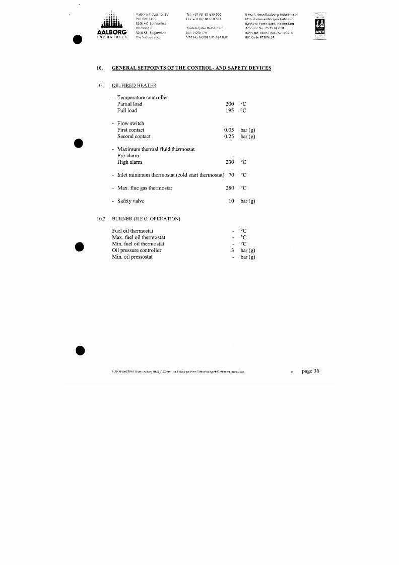
GENERAL SETPOINTS OF THE CONTR OL- AND SAFETY DEVICES
10.1 OIL FIRED HEATER
- Temperature controller
Partial load
Full load
- Flow switch
First contact
Second contact
- Maxim um thermal fluid thermostat
Pre-alarm
High alarm
200
195
0.05
0.25
-
230
°C
°C
bar (g)
bar(g)
°C
- Inlet minimum thermostat (cold start thermostat) 70 °C
- Max. flue gas thermostat 280 °C
Aalborg Industr ies BV Tel. +31 (0)181 650 500
E-mail: r tmw@aalborg-industr ies.nl
7/18/2019 M14 Thermal Fluid
http://slidepdf.com/reader/full/m14-thermal-fluid 38/486
AALBORG
I N D U S T R I E S
P.O. Box 145
3200 AC Spijkenisse
Ohmweg 8
3208 KE Spijkenisse
The Netherlands
Fax +31 (0)181 650 501
Traderegister Rotterdam
No. 24234179
VAT No. NL0081.91.694.B.01
ht tp : / /www.aalborg- indus t r ies .n l
Bankers; Fortis Bank, Rotterdam
Account No. 25.75.69.618
IBAN No. NL85FTSB0257569618
BIC Code FTSBNL2R
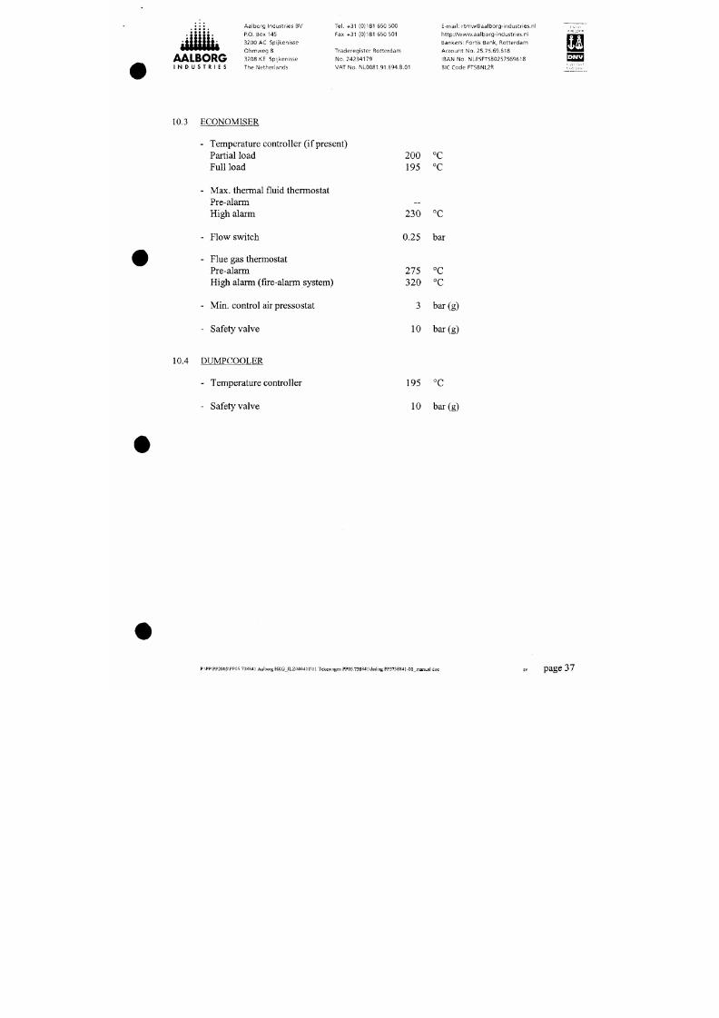
10.3 ECONOMISER
- Tem perature controller (if present)
Partial load
Full load
- Ma x. thermal fluid thermostat
Pre-alarm
High alarm
- Flow switch
- Flue gas thermostat
Pre-alarm
High alarm (fire-alarm system)
- Min. control air pressostat
- Safety valve
200 °C
195 °C
230 °C
0.25 bar
275 °C
320 °C
3 bar (g)
10 bar (g)
Aalborg Industr ies BV Tel. +31 (0)181 650 500
E-mail: r tmw@aalborg-industr ies.nl
7/18/2019 M14 Thermal Fluid
http://slidepdf.com/reader/full/m14-thermal-fluid 39/486
AALBORG
I N D U S T R I E S
P.O. Box 145
3200 AC Spijkenisse
Ohm w eg 8
3208 KE Spijkenisse
The Netherlands
Fax +31 (0)181 650 501
Traderegister Rotterdam
No. 24234179
VAT No. NL0081.91.694,6.01
ht tp : //www.aalborg- indus t r ies .n l
Bankers: Fortis Bank, Rotterdam
Account No. 25.75.69.618
IBAN No. NL85FTSB0257569618
SIC Code FTSBNL2R
^ ^
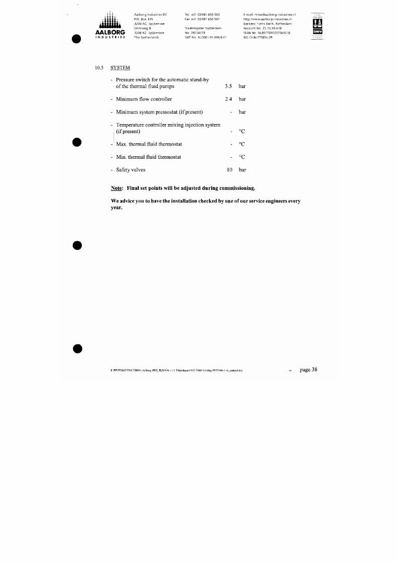
10.5 SYSTEM
- Pressure switch for the autom atic stand-by
ofthe thermal fluid pum ps 3.5 bar
- Minimum flow controller 2.4 bar
Minimum system pressostat (if present)
bar
Temperature controller mixing injection system
(if present)
Max. thermal fluid thermostat
°C
°C
Min. thermal fluid thermostat
Safety valves
- °C
10 bar
Note: Final set points will be adjusted during comm issioning.

7/18/2019 M14 Thermal Fluid
http://slidepdf.com/reader/full/m14-thermal-fluid 40/486
AALBORG
I N D U S T R I E S
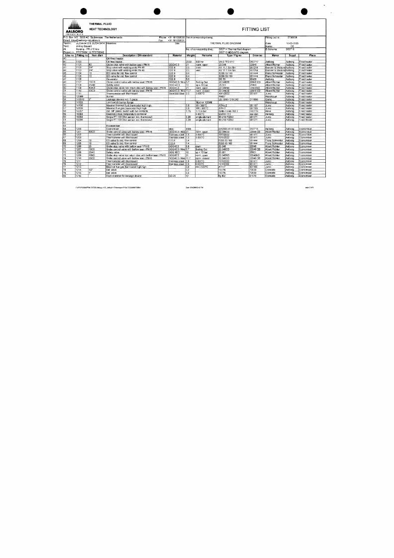
P.O. Box 1
Email:
rtmw
Yardnr.:
Yard:
45, 3200 AC
/@aalborg-ir
J LZ04-041 :
Jinling Sipy
At: Nanjing - P
Project nr.: PP573 8841
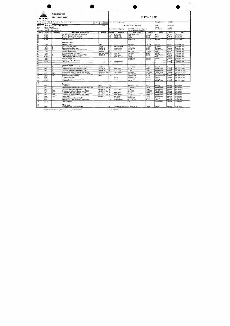
Line no
1
2
3
4
5
6
7
8
9
10
11
12
13
14
15
16
17
18
19
20
21
22
23
24
25
26
27
28
29
30
31
32
33
34
35
36
37
38
39
Fitting no
1001
1002
141S19
141S16
1010
1011
1012
1013
1014
1015
1016
1017
1018
1019
1020
1021
1022
1023
1024
1025
1030
1031
1032
1033
1034
1035
1036
1037
1038
1039
1040
1041
1042
20M10
20M14
30S12
THERMAL FLUID
HEAT TECHNOLOGY
; Spijkenisse, The Netherlands Phone:
idustr ies.nl F a x :
i & J L Z 0 4 - 0 4 1 4
ard
R of China
& PP5738842
Norn diam
100
100
15
100x1/2"
1/2"
1/2"
100
80
80ND
100x1/2"
1/2"
1/2"
15CD
1/2"
1/2"
100
100
15
100x1/2"
1/2"
1/2"
100
80
80ND
100x1/2"
1/2"
1/2"
/ i te ra t ions:
Description / D IN-standard
De-airat ing pipe
Temp, blocking pipe
Minimal therma l f luid thermostat inol thermowell
Maximal thermal f luid thermostat inci thermowell
Circ. pumps
Circulating pump with 15kW E-motor
Globe stop valve with bellow seal / PN16
St ra ine r /PN 16
Globe stop valve with bellow seal / PN16
Mano-vacuum meter glycerine f i l led
Manometer valve / PN40
Manometer syphon / PN40
Suction bellow with double braiding and f langes
Delivery bellow with double braiding and f langes
Globe stop valve non return disc with bellow seal / PN16
Mano-vacuum meter glycerine f i l led
Manometer valve / PN40
Manometer syphon / PN40
Globe control valve with bellow seal / PN16
Manometer valve with test connection / PN40
Manometer syphon / PN40
Circulating pump with 15kW
E-motor
Globe stop valve with bellow seal / PN16
S t r a i n e r / P N 1 6
Globe stop valve with bellow seal / PN16
Mano-vacuum meter glycerine f i l led
Manometer valve / PN40
Manometer syphon / PN40
Suction bellow with double braiding and f langes
Delivery bellow with double braiding and f langes
Globe stop valve non return disc with bellow seal / PN16
Mano-vacuum meter glycerine f i l led
Manometer valve / PN40
Manometer syphon / PN40
E-motor 15kW
E-motor 15kW
Auto stand-by pressostat ind. reducer 3/8"x1/2"
»-31 181650500
<-31 181650501
Date
•Mater ial
steel
steel
GGG40.3
GGG40.3
GGG40.3/Niro
GGG40.3
AISI-304/316
steel
steel
steel
steel
GGG40.3
AISI-304/316
steel
steel
GGG40.3 / Niro
steel
steel
GGG40.3
GGG40.3
GGG40.3/Niro
GGG40.3
AISI-304/316
steel
steel
steel
steel
GGG40.3
AISI-304/316
steel
steel
FITTING LIST
Titel of corresponding drawing:
THERMAL FLUID D IAGRAM
No .
of correspon dig dnwg.:
Weight
15
78
0,8
0,8
231,5
28
16
3,7
0.9
0,55
0,69
9,1
7,3
21
0.9
0,55
0,69
3,7
1
0,69
231,5
28
16
3,7
0.9
0,55
0,69
9,1
7,3
21
0.9
0,55
0,69
1
Remarks
50 / 300°C
50 / 300°C
Q=34m3/h H=80mlc
norm, open
drain
-1+3B
norm,
open
0-16B
keep hot
Q=34m3/h H=80mlc
norm,
open
drain
-1+38
norm,
open
0-16B
SP = 3,5 bar
D53714 Thermal f luid diagram
D53715 MDO/HFO d iagram
Type / Fig no
D50
5950
ATHs-2
ATHs-2
NTT 50-200
22.046
22.05
22.046
type 213.53.100
S004.16.100
S006.07.110
RFB
RFB
22.046ND
type 213.53.100
S004.16.100
S006.07.110
22.046CD
S004.60.100
S006.07.110
NTT 50-200
22.046
22.05
22.046
type 213.53.100
S004.16.100
S006.07.110
RFB
RFB
22.046ND
type 213.53.100
S004.16.100
S006.07.110
K P S 3 5
Draw no
90427
90429
951167
951167
D53720
22046
22050
22046
62053
941037
941041
90424
90424
22046ND
62053
941037
941041
22046 CD
941037
941041
D53720
22046
22050
22046
62053
941037
941041
90424
90424
22046ND
62053
941037
941041
941032
Fitfing List nr.:
Date:
Name:
E-Schema:
Maker
Aalborg
Aalborg
Jumo
Jumo
Allweiler
Albert Richter
Albert Richter
Albert Richter
Wika
Franz Schneider
Franz Schneider
Senior Flexonics
Senior Flexonics
Albert Richter
Wika
Franz Schneider
Franz Schneider
Albert Richter
Franz Schneider
Franz Schneider
Allweiler
Albert Richter
Albert Richter
Albert Richter
Wika
Franz Schneider
Franz Schneider
Senior Flexonics
Senior Flexonics
Albert Richter
Wika
Franz Schneider
Franz Schneider
Siemens
S iemens
Danfoss
5738659
16-03-2005
CE
D53716
SuppI
Aalborg
Aalborg
Aalborg
Aalborg
Aalborg
Aalborg
Aalborg
Aalborg
Aalborg
Aalborg
Aalborg
Aalborg
Aalborg
Aalborg
Aalborg
Aalborg
Aalborg
Aalborg
Aalborg
Aalborg
Aalborg
Aalborg
Aalborg
Aalborg
Aalborg
Aalborg
Aalborg
Aalborg
Aalborg
Aalborg
Aalborg
Aalborg
Aalborg
Aalborg
Aalborg
Aalborg
P lace
System
System
System
System
Circ. pumps
Circ. pumps
Circ. pumps
Circ. pumps
Circ. pumps
Circ. pumps
Circ. pumps
Circ. pumps
Circ. pumps
Circ. pumps
Circ. pumps
Circ. pumps
Circ. pumps
Circ. pumps
Circ. pumps
Circ. pumps
Circ. pumps
Circ. pumps
Circ. pumps
Circ. pumps
Circ. pumps
Circ. pumps
Circ. pumps
Circ. pumps
Circ. pumps
Circ. pumps
Circ. pumps
Circ. pumps
Circ. pumps
Circ. pumps
Circ. pumps
Circ. pumps
P:\PP\PP2004\PP04.737230.Aalborg HKG_JinllngM1 Tekeningen PP04.737230\ritl5738841
Date 12/4/2006 2:43 PM
page
1
of 5
7/18/2019 M14 Thermal Fluid
http://slidepdf.com/reader/full/m14-thermal-fluid 41/486
« ü t t i i ü
AALBORG
I N D U S T R I E S
P.O. Box 1
Email: rtmw
Yardnr.:
Yard:
At:
Project nr.:
Line no
40
41
42
43
44
45
46
47
48
49
50
51
52
53
54
55
56
57
58
59
60
61
62
63
64
65
66
67
68
69
70
71
72
73
74
75
76
77
78
79
80
45,
3200 AC
/@aalborg-ir
J LZ04-041 :
Jinling Sipy
Nanjing - P
PP5738841
Fitting no
1100
1101
1102
1103
1104
1105
1106
1107
1108
1109
1110
1111
120M6
141S12
141S3
141S6
141S9
142S7
160B3
160B4
160B6
1200
1201
1202
1203
1204
1205
1206
1207
1208
1209
1210
1211
1212
1213
1214
1215
1216
THERMAL FLUID
HEAT TECHNOLOGY
) Spijkenisse, The Netherlands Phone:
idustr ies.nl Fax:
& JLZ04-0414
ard
R of China
& PP5738842
Nom diam
80
3/4"
3/4"
10
10
15CD
25/40
80ND
65CD
2"
80CD
10
10
25
15CD
25/40
80ND
65CD
1/2"
1"
Alterations:
Description / DIN-standard
Oil fired heater
Oil f ired heater
Globe stop valve with bellow seal / PN16
Stop valve with welding ends PN 40
Stop valve with welding ends PN 40
EO valve for ind. f low control
EG valve for ind. f low control
De-aerator
Globe control valve with bellow seal / PN16
Safety valve
Globe stop valve n on return disc with bellow seal / PN16
Globe control valve with bellow seal / PN16
Thermometer with thermowell
Burner
Leakage devoce
incl.
T-piece
Limit switch burner f lange
Maximal thermal f luid thermostat high high
Maximal f lue gas thermostat high high
Ind. diff. press, switch with two contacts
Electronic mod. temperature controller
Single PT 100 Ohm sensor
incl.
thermowell
Single PT 100 Ohm sensor incl. thermowell
Economiser
Economiser
Globe control valve with bellow seal / PN16
Thermometer with thermowell
Thermometer with thermowell
EO valve for ind. f low control
EO valve for ind. f low control
Globe stop valve with bellow sea l / PN16
Globe control valve with bellow seal / PN16
Safety valve
Globe stop valve non return disc with bellow seal / PN16
Globe control valve with bellow seal / PN16
Thermometer with thermowell
Thermometer with thermowell
Maximal f lue gas thermostat high high
Ball valve
Ball valve
Float chamber for leakage device
*•3^ 181650500
t-31 181650501
Date
Material
GGG40.3
C22.8
C22.8
C22.8
C22.8
C22.8
GGG40.3 / Niro
GGG 40.3
GGG40.3
GGG40.3 / Niro
Stainless steel
steel
GGG40.3 / Niro
Stainless steel
Stainless steel
C22.8
022.8
GGG40.3
GGG40.3 / Niro
GGG 40.3
GGG40.3
GGG40.3 / Niro
Stainless steel
Stainless steel
GG-20
FITTING LIST
Titel of corresponding drawing:
THERMAL FLUID DIAGRAM
No . of correspondig drwg.:
Weight
2300
21
2,5
2,5
0,4
0,4
5,8
3,7
10
21
11,7
0.5
0,8
0,8
1,75
0,28
0,28
4500
21
0.5
0.5
0,4
0,4
8,8
3,7
10
21
11,7
0.5
0.5
0,8
0,2
0,5
12
Remarks
800 kw
norm,
open
drain
vent
Boiling Out
sp= 10 bar
norm,
open
norm, closed
0-500°C
f i t ted on 120M6
50 / 30 0°C
200 / 500°C
0
/ 0,6 bar
0-300°C
single element
single element
norm,
open
0-300°C
0-300°C
drain
Boil ing Out
sp= 10 bar
norm, open
norm, closed
0-500°G
0-500°C
200 / SOOX
D53714 Thermal f luid diagra
D53715 MDO/HFO diagram
Type / Fig no
V4-0-TFO-010
22.046
A V 1 1 . 1 S m S m
A V 1 1 . 1 S m S m
S338.03.160
S338.03.160
DE 50
22.046CD
25.901
22.046ND
22.046CD
10/1/2002
RMS7
LS-1950/010-242
ATHs-2
ATH-7
Delta Comb 702.2
93W00 701
90.210.F02/dl
90.210.F02/dl
EXV568-41-57.0-600
22.046CD
10/1/2002
10/1/2002
S338.03.160
S338.03.160
22.046
22.046CD
25.901
22.046ND
22.046CD
10/1/2002
10/1/2002
ATH-7
1607N
1607N
fig 802
m
Draw no
D53717
22046
951214
951214
951444
951444
90428
22046 CD
25901
22046ND
22046 CD
951411
D11855
951167
951165
D00776
see doc
901071
901071
D53718
22046 CD
951411
951411
951444
951444
22046
22046 CD
25901
22046ND
22046 CD
951411
951411
951165
72859
72859
61670
Fitting List nr.:
Date:
Name:
E-Schema:
Maker
Aalborg
Albert Richter
5738659
16-03-2005
CE
D53716
SuppI
Aalborg
Aalborg
Deinzer & Weilanc Aalborg
Deinzer & Weilanc Aalborg
Franz Schneider
Franz Schneider
Aalborg
Albert Richter
Albert Richter
Albert Richter
Albert Richter
Jumo
Weishaupt
Gems
Weishaupt
Jumo
Jumo
Wika
Aalborg
Jumo
Jumo
Aalborg
Albert Richter
Jumo
Jumo
Franz Schneider
Franz Schneider
Albert Richter
Albert Richter
Albert Richter
Albert Richter
Albert Richter
Jumo
Jumo
Jumo
Econosto
Econosto
Econosto
Aalborg
Aalborg
Aalborg
Aalborg
Aalborg
Aalborg
Aalborg
Aalborg
Aalborg
Aalborg
Aalborg
Aalborg
Aalborg
Aalborg
Aalborg
Aalborg
Aalborg
Aalborg
Aalborg
Aalborg
Aalborg
Aalborg
Aalborg
Aalborg
Aalborg
Aalborg
Aalborg
Aalborg
Aalborg
Aalborg
Aalborg
Aalborg
Aalborg
Aalborg
Place
Fired heater
Fired heater
Fired heater
Fired heater
Fired heater
Fired heater
Fired heater
Fired heater
Fired heater
Fired heater
Fired heater
Fired heater
Fired heater
Fired heater
Fired heater
Fired heater
Fired heater
Fired heater
Fired heater
Fired heater
Fired Heater
Economiser
Economiser
Economiser
Economiser
Economiser
Economiser
Economiser
Economiser
Economiser
Economiser
Economiser
Economiser
Economiser
Economiser
Economiser
Economiser
Economiser
P:\PP\PP2004\PP04.737230.Aalboig HKG_Jinling \11 Tekening en PP04.737230\fltl57388 41 Date 12/4/20O6 2:43 PM
page 2 of 5
7/18/2019 M14 Thermal Fluid
http://slidepdf.com/reader/full/m14-thermal-fluid 42/486
AALBORG
I N D U S T R I E S
P.O. Box 1
Email:
rtmv
Yardnr.:
Yard:
At:
Project nr.:
Line no
81
82
83
84
85
86
87
88
89
90
91
92
93
94
95
96
97
98
99
100
101
102
103
104
105
106
107
108
109
110
111
112
113
114
115
116
117
118
119
120
121
122
123
45,
3200 AC
/@aalborg-l
J LZ04-041 ;
Jinling Sipy
Nanjing - P
PP5738841
Fitting no
91S2
91S4
91S6
91S8
1300
1301
1302
1303
1304
1305
1306
40S11
40S14
40S17
40S8
1400
1401
1402
1403
1404
1405
9087
9082
90Y5
1450
1451
1452
1453
1454
1455
1456
8982
8987
89Y5
1510
THERMAL FLUID
HEAT TECHNOLOGY
/ Spijkenisse, The Netherlands Phone:
idustr ies.nl Fax:
i & JLZ04-0414
ard
R of China
& PP5738842
Norn diam
25
65
25
50
50
65
65
40CD
1/2"
1/2"
65
80
65CD
80
50CD
25/40
/Mterations;
Description / DIN-standard
Ind. diff. press, switch with two contacts
IVIaximal thermal fluid thermostat
IVIaximal flue gas thermostat high
Level switch high
Expansion tanl(
Expansion tank
Self closing drain valve
Quick opening globe valve
Globe stop valve with bellow seal / PN16
IVIagnetic level gauge
Thermometer with thermowell
Globe stop valve with bellow seal / PN16
Level switch low (reedoontact)
Level switch low low
Level switch high high
Limit switch
IMin.
f low control
Elect, controlled two-way valve with bellow se al
Globe stop valve with bellow seal / PN1 6
Globe stop valve with bellow seal / PN 16
Globe control valve with bellow seal / PN16
Manometer valve with test connection / PN40
Manometer syphon / PN40
Pressure transmitter
Modulating elec. pressure controller
Electr ic actuator
Dumpcooler
Dumpcooler
Electr ic controlled three-way valve with bellow s eal
Globe stop valve with bellow seal / PN16
Globe control valve with bellow seal / PN16
Globe stop valve with bellow seal / PN16
Globe control valve with bellow seal / PN 16
Safety valve
Modulating temperature controller
Single PT 100 Ohm sensor
incl.
thermowell
Electr ic actuator
Filling pum p
Fil l ing pump with 0,63 kw E-motor
f31 181650500
1-31 181650501
Date
IMaterial
steel
C. steel
GGG40.3
GGG40.3
AISI-304
Stainless steel
GGG40.3
GGG40.3
GGG40.3
GGG40.3
G G G 4 0 . 3 / N i r o
steel
steel
steel
G G G 4 0 . 3 / N i r o
GGG40.3
G G G 4 0 . 3 / N i r o
GGG40.3
G G G 4 0 . 3 / N i r o
GGG40.3
FITTING LIST
Titel of
corresponding
drawing:
THERMAL FLUID D IAGRAM
No .
of correspondig drwg.:
Weight
1,75
0,8
0,8
3
5,3
21
5,1
15
0.5
11,7
0,2
3
3
0,2
19,5
14,7
14,7
8,8
1
0,69
197
35,5
14,7
11,7
14,7
11,7
10
0,28
41
Remarks
0 / 0,6 bar
50 /300°C
200 / 500°C
Norm,
closed
norm,
closed
norm,
closed
0-160°C
norm,
open
fit ted on 1304
Fitted on 1302
norm,
open
norm,
open
norm,
closed
0-6 bar
0-6 bar
norm,
open
norm,
open
norm,
closed
sp=10 bar
0 - 300°C
single element
Q=2,5m3/h H=4 bar
D53714 Thermal f luid diagram
D53715 MDO/HFO diagram
Type / Fig no
Delta Comb 702.2
ATHs-2
ATH-7
S01DB/F84
SVE 5950
574
100/432SO
22.046
ITA-3,0-GL
10/1/2002
22.046
LMS-A
S01DB/F84
S01DB/F84
23.441/PR2.2
22.046
22.046
22.046CD
3004,60.100
S006.07.110
IVIBS33M (rel)
93W00 70E
PR2.2
M X 2 0 T 1 0 L = 1 2 0 0
23.451/PR2.2
22.046
22.046CD
22.046
22.046CD
25.901
93W00 700
90.210.F02/dl
PR2.2
KF25 RF2-D15
Draw no
D00776
951167
951165
D00734
D53719
D00894
90236
22046
D01054
951411
22046
D00734
D00734
73851
22046
22046
22046 CD
941037
941041
951182
see doc
D53721
72903
22046
22046 CD
22046
22046 CD
25901
see doc
901071
61943
Fitting List nr.:
Date:
Name:
E-Schema:
IVIalter
Wika
Jumo
Jumo
Mobrey
Aalborg
Econosto
Econosto
Albert Richter
Intra
Jumo
Albert Richter
Intra
Mobrey
Mobrey
Albert Richter
Albert Richter
Albert Richter
Albert Richter
Franz Schneider
Franz Schneider
Danfoss
Aalborg
Albert Richter
Aalborg
Albert Richter
Albert Richter
Albert Richter
Albert Richter
Albert Richter
Albert Richter
Aalborg
Jumo
Albert Richter
Kracht
5738659
16-03-2005
CE
D53716
SuppI
Aalborg
Aalborg
Aalborg
Aalborg
Aalborg
Aalborg
Aalborg
Aalborg
Aalborg
Aalborg
Aalborg
Aalborg
Aalborg
Aalborg
Aalborg
Aalborg
Aalborg
Aalborg
Aalborg
Aalborg
Aalborg
Aalborg
Aalborg
Aalborg
Aalborg
Aalborg
Aalborg
Aalborg
Aalborg
Aalborg
Aalborg
Aalborg
Aalborg
Aalborg
Aalborg
Place
Economiser
Economiser
Economiser
Economiser
Expansion tank
Expansion tank
Expansion tank
Expansion tank
Expansion tank
Expansion tank
Expansion tank
Expansion tank
Expansion tank
Expansion tank
Expansion tank
Min. f low control
Min . f low control
Min. f low control
Min.
f low control
Min.
f low control
Min. f low control
Min .
f low control
Min .
f low control
Min.
f low control
Dumpcooler
Dumpcooler
Dumpcooler
Dumpcooler
Dumpcooler
Dumpcooler
Dumpcooler
Dumpcooler
Dumpcooler
Dumpcooler
Fil l ing pump
P:\PP\PP2004\PP04.737230.Aalborg
HKG_JinlingM
1
Tekeningen PP04.737230\ritl5738841 Date 12/4/2006 2:43 PM
7/18/2019 M14 Thermal Fluid
http://slidepdf.com/reader/full/m14-thermal-fluid 43/486
• • • • • • • • • H E A T T E C H N O L O G Y
AALBORG
I N D U S T R I E S
P.O. Box 1
Email:
rtm\A
Yardnr.:
Yard:
45,
3200 AC
/@aalborg-ir
J LZ04-041 :
Jinling Sipy
; Spijkenisse, The Netherlands Phone: +31 181650500
idustr ies.nl Fax: +31181650501
i & JLZ04-0414
ard
At: Nanjing - PR of China
Project nr.: PP5738841 & PP5738842
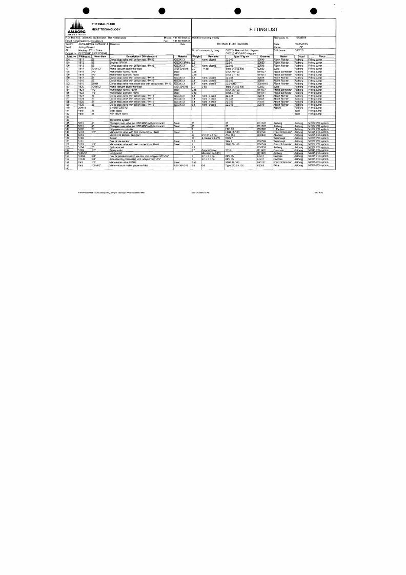
Line no
124
125
126
127
128
129
130
131
132
133
134
135
136
137
138
139
140
141
142
143
144
145
146
147
148
149
150
151
152
153
154
155
156
157
158
159
160
Fi t t ing no
1511
1512
1513
1514
1515
1516
1517
1518
1519
1520
1521
1522
1523
1524
1525
1526
20M18
Yard
Yard
5001
5001
5002
5003
5010
5100
5101
5103
5104
5105
180S12
180S6
31S12
Yard
Yard
Nom d iam
25
25
25
100x1/2"
1/2"
1/2"
25
25
25ND
100x1/2"
1/2"
1/2"
25
25
25
25
25
25
40
40
20
1/2"
1/2"
25
1/2"
3/8"
3/8"
1/2"
100x1/2"
/iterations: Date
Descr ip t ion / D IN-standard
Globe stop valve with bellow seal / PN16
St ra iner /PN16
Globe stop valve with bellow seal / PN16
Mano-vacuum glycerine f i l led
Manometer valve / PN40
Manometer syphon / PN40
Globe stop valve with bellow seal / PN16
Globe stop valve with bellow seal / PN16
Globe stop valve non return disc with bellow seal / PN16
Mano-vacuum glycerine f i l led
Manometer valve / PN40
Manometer syphon / PN40
Globe stop valve with bellow seal / P N16
Globe stop valve with bellow seal / P N16
Globe stop valve with bellow seal / P N16
Globe stop valve with bellow seal / P N16
E-motor 0,63 kw
Sight glass
Non return valve
IVIDO/HFO sy stem
Changes over valve set HFO/MDO with l imit switch
Changes over valve set HFO/MDO with l imit switch
Oil pressure controller
Manometer valve with test connection / PN40
MDO/HFO Booster pumpset
Burner
Fuel oi l de-aerator
Manometer valve with test connection / PN40
Ball valve set
Safety valve
Limit switch
Fuel oi l pressure switch low low, incl.:adaptor 3/8"x1/2"
Auto standby pressostat, incl. :adaptor3/8"x1/2"
Manometer valve / PN40
Mano-vacuum meter glycerine f i l led
•Material
GGG40.3
GGG40.3/Niro
GGG40.3
AISI-304/316
steel
steel
GGG40.3
GGG40.3
GGG40.3
AISI-304/316
steel
steel
GGG40.3
GGG40.3
GGG40.3
GGG40.3
Steel
Steel
Steel
Steel
Steel
Steel
AISI-304/316
FITTING LIST
Titel of corresponding drawing:
THERMAL FLUID D IAGRAM
No .
of correspondig drwg.: D53714 Thermal fluid diagram
D53715 MDO/HFO diagram
W e i g h t
5,1
5,5
5,1
0.9
0,55
0,69
5,1
5,1
5,1
0.9
0,55
0,69
5,1
5,1
5,1
5,1
25
25
1
1
62
111
6.5
1
1.2
0.7
1
1
0.55
0.9
Remar l (s
norm, closed
norm,
closed
-1+3B
norm, closed
norm,
closed
norm, closed
0-6B
norm,
closed
norm,
closed
norm,
closed
norm,
closed
672 l/h 2-5 bar
E-Heater
2.6 kW
Setpoint 8 bar
Mounted on 5001
SP = 3,5 bar
SP = 3.5 bar
0-6
Type / F ig no
22.046
22.05
22.046
Type 213.53.100
S004.16.100
S006.07.110
22.046
22.046
22.046ND
Type 213.53.100
S004.16.100
8006.07.110
22.046
22.046
22.046
22.046
25
25
FDR 20
S004.60.100
ZAS 550
RMS 7
Size 2
S004.60.100
1515
K P S 3 5
K P S 3 5
S004.16.100
Type 213.53.100
Draw no
22046
22050
22046
62053
941037
941041
22046
22046
22046ND
62053
941037
941041
22046
22046
22046
22046
D01026
D01026
D00800
D00749
D00840
D00799
D00749
D00839
D11428
D01026
61727
61727
941037
62053
Fitting List nr.: 5738 659
Date:
16-03-2005
Name:
CE
E-Schema: D53716
•Maker
Albert Richter
Albert Richter
Albert Richter
Wika
Franz Schneider
Franz Schneider
Albert Richter
Albert Richter
Albert Richter
Wika
Franz Schneider
Franz Schneider
Albert Richter
Albert Richter
Albert Richter
Albert Richter
Kracht
Aalborg
Aalborg
H.Paulsen
Franz Schneider
Allweiler
Weishaupt
Weishaupt
Franz Schneider
Aalborg
Econosto
Aalborg
Danfoss
Danfoss
Franz Schneider
Wika
Suppi
Aalborg
Aalborg
Aalborg
Aalborg
Aalborg
/Aalborg
Aalborg
Aalborg
Aalborg
Aalborg
Aalborg
Aalborg
Aalborg
Aalborg
Aalborg
Aalborg
Aalborg
Yard
Yard
Aalborg
Aalborg
Aalborg
Aalborg
Aalborg
Aalborg
Aalborg
Aalborg
Aalborg
Aalborg
Aalborg
Aalborg
Aalborg
Aalborg
Aalborg
P lace
Fil l ing pump
Fil l ing pump
Fil l ing pump
Fil l ing pump
Fil l ing pump
Fil l ing pump
Fil l ing pump
Fil l ing pump
Fil l ing pump
Fil l ing pump
Fil l ing pump
Fil l ing pump
Fil l ing pump
Fil l ing pump
Fil l ing pump
Fil l ing pump
Fil l ing pump
Fil l ing pump
Fil l ing pump
MDO/HFO system
MDO/HFO system
MDO/HFO system
MDO/HFO system
MDO/HFO system
MDO/HFO system
MDO/HFO system
MDO/HFO system
MDO/HFO system
MDO/HFO system
MDO/HFO system
MDO/HFO system
MDO/HFO system
MDO/HFO system
MDO/HFO system
P:\PP\PP2004\PP04.737230.Aalborg HKG_Jinling\11 Takaningen PP04.737230\ffll5738841 Dale 12/4/2006 2:43 PM
page 4 of 5

7/18/2019 M14 Thermal Fluid
http://slidepdf.com/reader/full/m14-thermal-fluid 44/486
• • • " " • ' H EA T T EC H NO L OG Y
AALBORG
I N D U S T R I E S
P 0. Box 1
Email:
rtmvi
Yardnr.:
Yard:
45,
3200 AC
/@aalborg-ir
J LZ04-041 :
Jinling Sipy
; Spijkenisse, The Netherlands Phone: +31 181650500
idustr ies.nl Fax: +31181650501
i & JLZ04-0414
ard
At: Nanjing - PR of China
Project nr; PP5738841 & PP5738842
Line no
161
162
163
164
165
166
167
168
169
170
171
172
173
174
175
176
177
178
179
180
181
182
183
184
185
186
187
188
189
190
191
192
193
194
195
Fi t t ing no
9001
9002
9003
9004
9005
9006
9007
9100
9101
9102
9103
9104
9105
9106
9107
9108
9109
9110
9200
9201
9202
9300
9301
9302
9303
9304
9305
9306
9307
9308
9309
Nom d iam
1 pc
1 pc
1 pc
1 pc
2 PC
2pc
1 pc
1 pc
1 pc
2 PC
2 p c
1 pc
2 p c
2 p c
1 pc
1 pc
2 p c
2 p c
1 pc
1 pc
1 pc
1 pc
1 pc
1 pc
1 pc
1 pc
1 pc
1 pc
1 pc
1 pc
10 PC
Alterations: Date
Descr ip t ion / D IN-standard
Spare par ts
IVIodulating Nozzle
Ignit ion electrode left
Ignit ion electrode r ight
Flame sensor RAR7
Rubber cross coupling
Ignit ion cables complete
Coupling for burner pump
Joint 400.1
Joint 400.3
Gland seal packing 461.01
Joint 411.06/07
IVIechanical seal 433.01 (IVI3N4/32-SBVGG)
Distance washer 551.4/5
Circl ip 932.02/04
Washer 932.01
Seegerr ing 936.01
Ball bearings for Pump
Ball bearing for E-motor
PT 100 ohm sensor
Max. thermal f luid thermostat type ATH-SE-20
Max. f lue gas thermostat type ATH-SE-20
Aux relais
Aux relais
Aux relais
Signal lamp glass green
Signal lamp glass red
Signal lamp glass yellow
Signal lamp glass blue
Signal lamp glass white
Lampholder complete
Lampbulbs
Mater ia l
FITTING LIST
Titel of corresponding drawing:
THERMAL FLUID D IAGRAM
No . of correspondig drvig.: D53714 Thermal f luid diagram
D53715 MDO/HFO diagram
Weigh t Remarks Type / F ig no
212 163 1020/7
212 163 1021/7
111 964 1201/2
111 151 0901/2
111 782 0901/2
ALXA402
ALXA403
ALR 060782
ALR049680
ALXA 551
ALXA 932
ALXA932
ALXA936
ALR0112062
6309-2Z
90.21-F02/dl
ATH-SE-20
ATH-SE-20
CAD32P7
CAD32P7
CAD50P7
ZB-V03
ZB-V04
ZB-V05
ZB-V06
ZB-V07
Draw no
Fitting List nr.:
Date:
Name:
E-Schema:
Maker
Monarch
Monarch
Monarch
Monarch
Monarch
Monarch
Monarch
Allweiler
Allweiler
Allweiler
All Weiler
Allweiler
Allweiler
Allweiler
Allweiler
Allweiler
Allweiler
Allweiler
Jumo
Jumo
Jumo
Telemecanique
Telemecanique
Telemecanique
Telemecanique
Telemecanique
Telemecanique
Telemecanique
Telemecanique
Telemecanique
5738659
16-03-2005
CE
D53716
SuppI
Aalborg
Aalborg
Aalborg
Aalborg
Aalborg
Aalborg
Aalborg
Aalborg
Aalborg
Aalborg
Aalborg
Aalborg
Aalborg
Aalborg
Aalborg
Aalborg
Aalborg
Aalborg
Aalborg
Aalborg
Aalborg
Aalborg
Aalborg
Aalborg
Aalborg
Aalborg
Aalborg
Aalborg
Aalborg
Aalborg
Aalborg
P lace
Spares for Burner
Spares for Burner
Spares for Burner
Spares for Burner
Spares for Burner
Spares for Burner
Spares for Burner
Spares for circ. Pump
Spares for circ. Pump
Spares for circ. Pump
Spares for circ. Pump
Spares for circ. Pump
Spares for circ. Pump
Spares for circ. Pump
Spares for circ. Pump
Spares for circ. Pump
Spares for circ. Pump
Spares for circ. Pump
Spares for Safeties
Spares for Safeties
Spares for Safeties
Spares for Control Box
Spares for Control Box
Spares for Control Box
Spares for Control Box
Spares for Control Box
Spares for Control Box
Spares for Control Box
Spares for Control Box
Spares for Control Box
Spares for Control Box
P;\PP\PP2004\PP04.737230.Aalborg HKG_JinlingM
1
Tekening en PP04.737230Mitl5738841 Date 12/4/2006 2:43 PM
page 5 of 5
WTESnWP
06-12-04
U:13J2
JUL
I
8 I 9 I 10 I 11 I 12 "
I '* I ^^~T
16
1 7
I 1'8
•J9 20
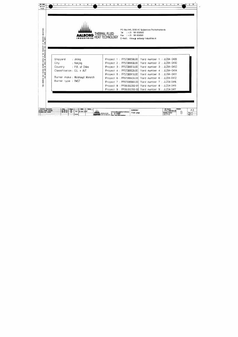
7/18/2019 M14 Thermal Fluid
http://slidepdf.com/reader/full/m14-thermal-fluid 45/486
3
i
Li. ^
^ Q:
o; o
UJ l i .
o.
o Q
o: UJ
o. o
UJ a
I - o:
«2 ul
(K
"->
UJ _
-^ Ul
i
o tu
s •"
o z
-i
1
o <
z
i
o
< / )
/ S S S S f t TH ER M AL F L U ID
™
r S ^ ? S ? ? ?
HEAT
T E C H N O L O G Y 'Zo,
PO Box 145, 3200 AC Spijkenisse The Netherlands
+31 181 650500
+31 181650501
rtmw @ aa lborg- industr ies.n l
Shipyard
City
Count ry
C lass i f ica t ion
Burner make
Burner type
Jinling
Nanjing
P.R. of China
Gl. + AUT
Welshaupt Monarch
RMS7
Pro ject 1
Pro je c t 2
Pro ject 3
Pro ject 4
Pro ject 5
Pro ject 6
Pro ject 7
Pro ject 8
Pro ject 9
PP5738659A.00
PP5738660A.00
PP5738661A.0O
PP5738862A.00
PP5738841A.00
; PP5738842A.00
PP5739698A,00
; PP06.052352-01
: PP06.052352-02
Yard
Yard
Yard
Yard
Yard
Yard
Yard
Yard
Yard
nunnber 1
nunnber 2
number 3
number 4
number 5
number 6
number 7
number 8
number 9
; JLZ04-0409
; JLZ04-0410
: JLZ04-0413
; JLZ04-0414
; JLZ04-0411
JLZ04-0412
JLZ04-0416
: JLZ04-0415
JLZ04-0417
Yard number chonQ«d
Reviaion Dgscription
Added ygrj number
Dots
0 5 -0 8 -2 9
06-04-20
Noma
RP
OS
Dot«
05-04-25
RP
Noma
,|{{}{{i,
THERMAL FLUID
HEAT TECHNOLOGY
PO amM^imm
n r-Mi inagos»
F« :+3\ ISISaOSOl
OILFIREDHEAT
Front page
Job Number
PP5738659A.0CI
Drowing number
D53716
Revision
B
A3
Page
1 0
Next
11
DMESTMIP
06-12-04
14:13:17
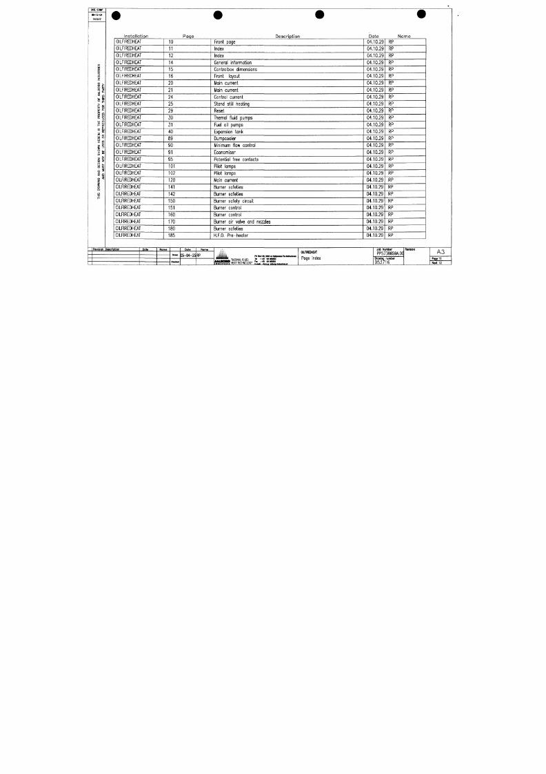
7/18/2019 M14 Thermal Fluid
http://slidepdf.com/reader/full/m14-thermal-fluid 46/486
i
i
UJ Li.
O.
O Q
o: iij
o. u
E o
« &j
o:
1
li
o <
z
i
o
I n s ta l l a t i o n
OILFIREDHEAT
OILFIREDHEAT
OILFIREDHEAT
OILFIREDHEAT
OILFIREDHEAT
OILFIREDHEAT
OILFIREDHEAT
OILFIREDHEAT
OILFIREDHEAT
OILFIREDHEAT
OILFIREDHEAT
OILFIREDHEAT
OILFIREDHEAT
OILFIREDHEAT
OILFIREDHEAT
OILFIREDHEAT
OILFIREDHEAT
OILFIREDHEAT
OILFIREDHEAT
OILFIREDHEAT
OILFIREDHEAT
OILFIREDHEAT
OILFIREDHEAT
OILFIREDHEAT
OILFIREDHEAT
OILFIREDHEAT
OILFIREDHEAT
OILFIREDHEAT
OILFIREDHEAT
Pcqe
10
11
12
14
15
16
20
21
24
25
29
30
31
40
89
90
91
95
101
102
120
141
142
150
151
160
170
180
185
De sc r i p t i o n
Front page
Index
Index
General information
Controlbox dimensions
Front layout
Main current
Main current
Control current
Stand still heating
Reset
Themal fluid pumps
Fuel oi l pumps
Expansion tank
Dumpcooler
Minimum flow control
Economiser
Potential free contacts
Pilot lamps
Pilot lamps
Main current
Burner safeties
Burner safeties
Burner safety circuit
Burner control
Burner control
Burner ai r valve an d nozzles
Burner safeties
H.F.O. Pre-heoter
Date
04.10.29
04.10.29
04.10.29
04.10.29
04.10.29
04.10.29
04.10.29
04.10.29
04.10.29
04.10.29
04.10.29
04.10.29
04.10.29
04.10.29
04.10.29
04.10.29
04.10.29
04.10.29
04.10.29
04.10.29
04.10.29
04.10.29
04.10.29
04.10.29
04.10.29
04.10.29
04.10.29
04.10.29
04.10.29
Na me
RP
RP
RP
RP
RP
RP
RP
RP
RP
RP
RP
RP
RP
RP
RP
RP
RP
RP
RP
RP
RP
RP
RP
RP
RP
RP
RP
RP
RP
Rflvlaion Daacription
Dote
Noma Data
35-04-25 RP
Nama
(iiiiiij^
THERMAL FLUID
HEAT TECHNOLOGY
P O l a i l M i a o O A C ^ I I n k H l l M l t a l l M M n ^
ra :-)« laieoono
F B i+ai
isiuosoi
E-<HJ: rtnwa adbaiu liitirtilMjii
OIUHREDHEAT
Page index
Job Number
PP5738659A.0a
Drawing number
D53716
R e v i s i o n
A3
Poge 11
Next 12
MIESTMIP
06-12-04
14:13:12
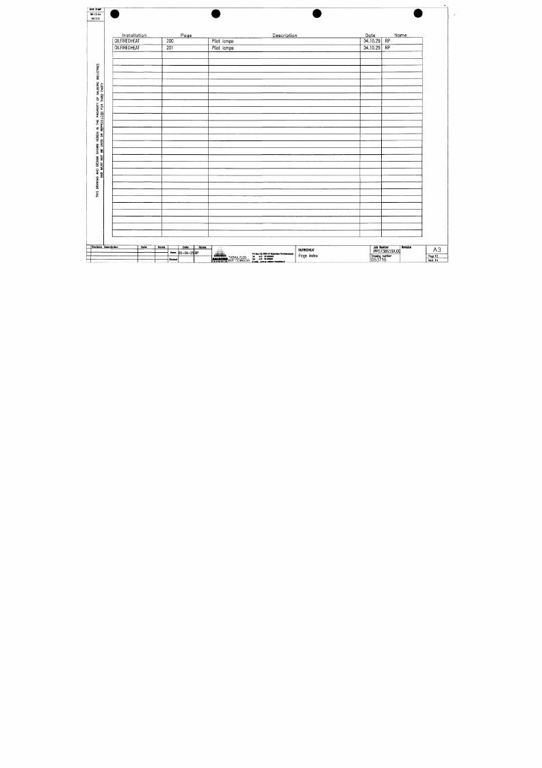
7/18/2019 M14 Thermal Fluid
http://slidepdf.com/reader/full/m14-thermal-fluid 47/486
i
o
o:
o
3
c- 0^
b: o
LU L-
o Q
o: ui
Q. O
i= o:
« Si
o:
z
i-
O UJ
S""
o z
< " 1 _
O <
z
i
Insta l la t ion
OILFIREDHEAT
OILFIREDHEAT
Paqe
200
201
Descrip t ion
Pilot lamps
Pilot lamps
Date
04.10.29
04.10.29
Name
RP
RP
Revision Degcription
Pote
Norne
Dote
D5-04-25 RP
Norne
THERMAL FLUID
HEAT TECHNOLOGY
po B>i4&a
n r-Mi imaaoaoo
F M :-f31 181100601
E-mal: rtnw o^wu tHtwIilMiJ
OimREDHEAT
Page index
Job Number
PP5738659A.0q
browing nunnber
D53716
Revision
A3
Page 12
Next 14
•
*
I
V
C
^o"ea
O
—
r
M
^
(
O
i
n
•
r
o
C
-
m
1
i
T
^
s
S
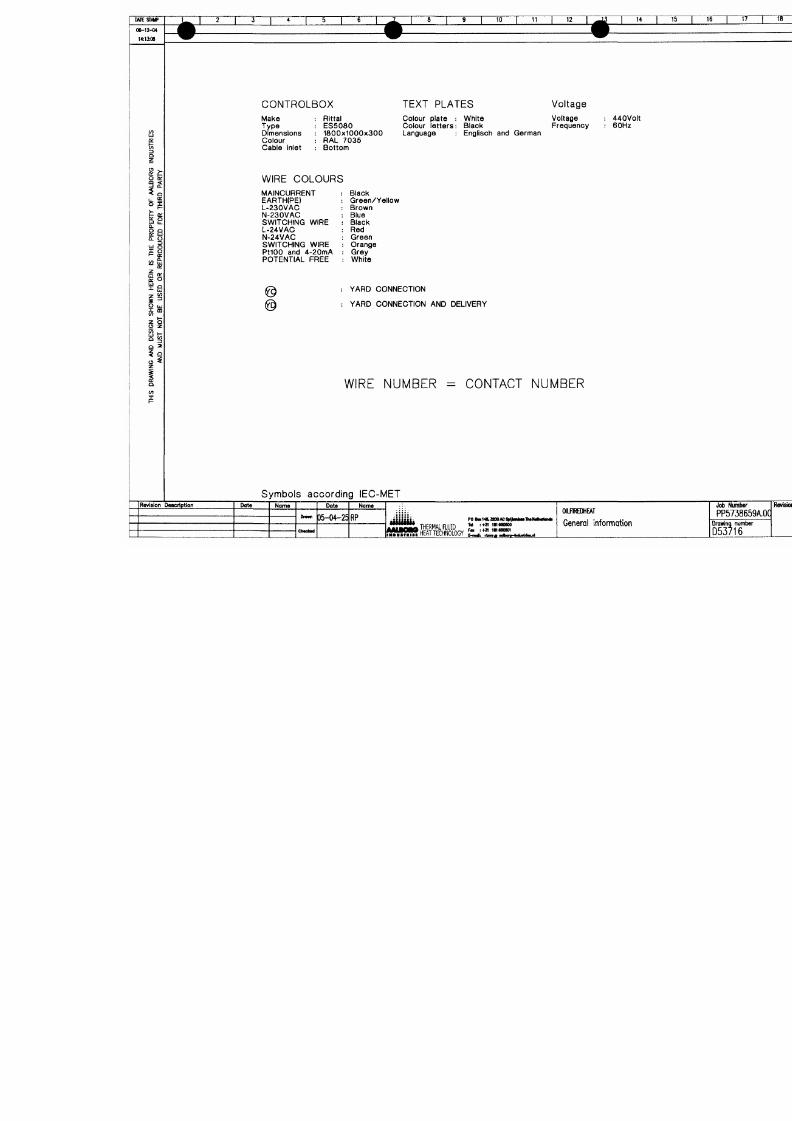
7/18/2019 M14 Thermal Fluid
http://slidepdf.com/reader/full/m14-thermal-fluid 48/486
O
)
C
"5>
L
U
1
—
<
_
CXL
U
1
—
X
om
_
j
o
C
-
o
Ü
o
>
N
o
x
•
*
o
•
>
D
Ü
S
=
2
C
O
w
>
L
L
C
C
Eo
O
•
o
co
S
t
o
0
C
1
_
0
^
=
2
o
o
e
o
o
§
Ü
Ü
"
ooC
O
O
o
^
.
t
c
o
c
u
^
æ
t
D
c
<
D
o
c
C
>
,
£
o
<
2
I
-
Q
O
Ü
s
a
s
N
io
«>
C
D
C
3
0
D
C
Q
0
D
Q
C
C
3
O
O
>
C
D
C
<
3
U
l
U
c
l
J
O
l
r
C
3
^
-
>
2
l
L
I
_
j
Z
C
0
_
i
Z
C
0
ü
.
ü
.
A
y
a
H
y
o
a
o
o
w
JO
A
a
3
H
s
>tL
>
_
U
QQZ
<
z
z
o
o
H
1
-
Ü
O
U
U
z
z
z
z
o
o
o
o
Q
Q
C
C
<
<
>
>
©
y
o
a
3
N
3
H
N
M
eÜ
J
mI
D
z
1
—
Ü<I
—
zoo
I
QL
Ü
m
3z
U
e
i
O
S
W
Q
N
S
Q
O
M
MTESr/W
06-12-04
H:13K)3
J ^
1 2 1 3 1 4 1 5 1 6 1 ^ ^ 1 8 1 9 1 10 1 11 1 12
1 .^i
| 14 | 15 | 16 | 17 | 18 L ^ 9
m
w w w
W ^ ^ ^ ^ ^ ^
FRDNT-VIEW SIDE-VIEW GROUND PLATE
1 20
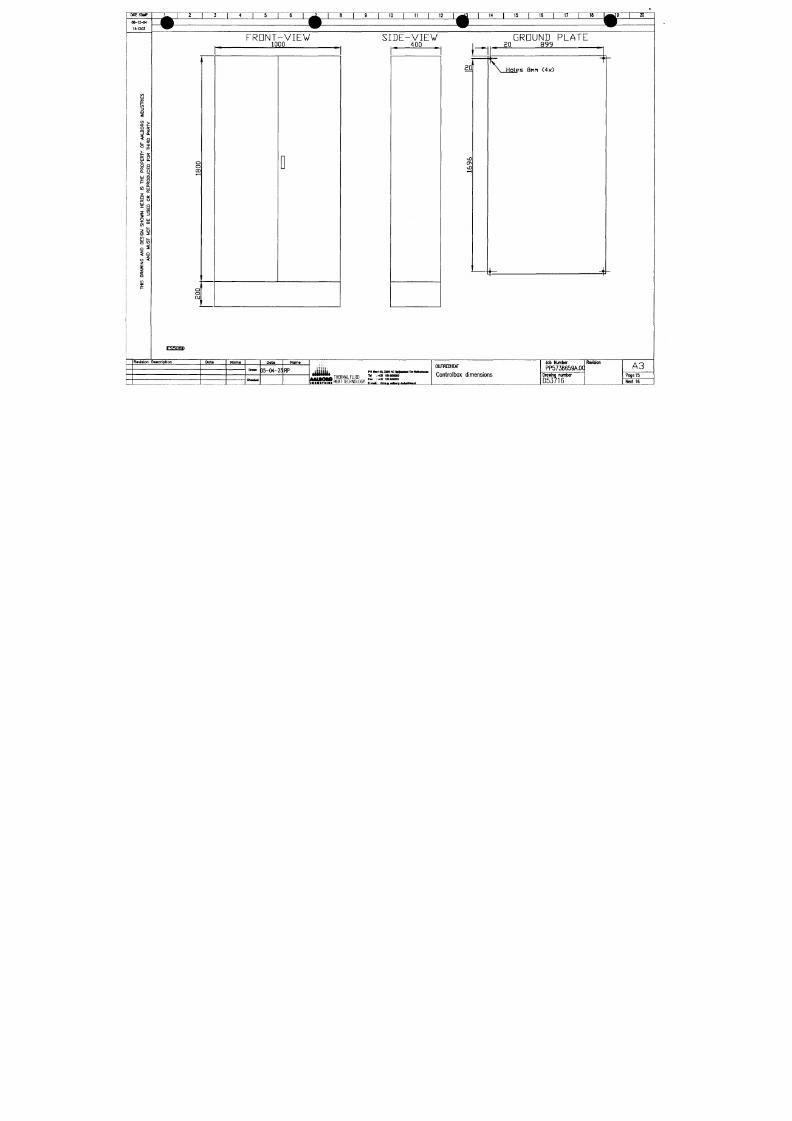
7/18/2019 M14 Thermal Fluid
http://slidepdf.com/reader/full/m14-thermal-fluid 49/486
i
5
Cl
z
«3 •>-
9 2
$ o
L.
^
°f
æ O
UJ u.
Q-
O Q
tr UJ
Q. Ü
r)
u
o
?=
o
f- o;
w
u3
o:
°g
x f ü
i^'
O UJ
S""
z S
o z
Q 3
^9
o <
z
i
Rovision
o
o
00
*—
C 3
O
OJ
1
'
i
1000
D
400
20
>X)
ON
^—1
'
20 899
' ^
\
Holes 8mn (4x)
i- 4
FS.M1HII
Description
Data Norne
nr,^
ClMck«d
Dote
D5-04-25
Name
RP
« " « # 1 1 *
THERMAL FLUID
1* : J
IS ISS?
OltflREDHEAT
Controlbox dimensions
Job Number
PP5738659A.0C
Drawing number
D53716
Revision
A3
Poge 15
Next 16
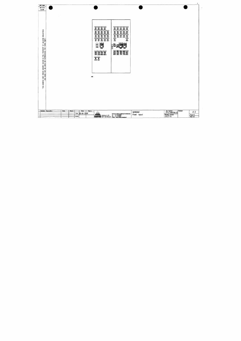
7/18/2019 M14 Thermal Fluid
http://slidepdf.com/reader/full/m14-thermal-fluid 50/486
9
C
i
pVS
j
ivno
^V
mV3
w
m
B
d
•
A
t
B
PP
^
Z8
T
l
•
I
T
HKD
n
«WM
ITT
tS
iwou
w
T
nWK
r
MM
I
immm
r
MT E STAMP
0S-12-«
mn
l l I 9 I 10
12
I 14 I 15 I TT 17
" • I ^ 9 I 20
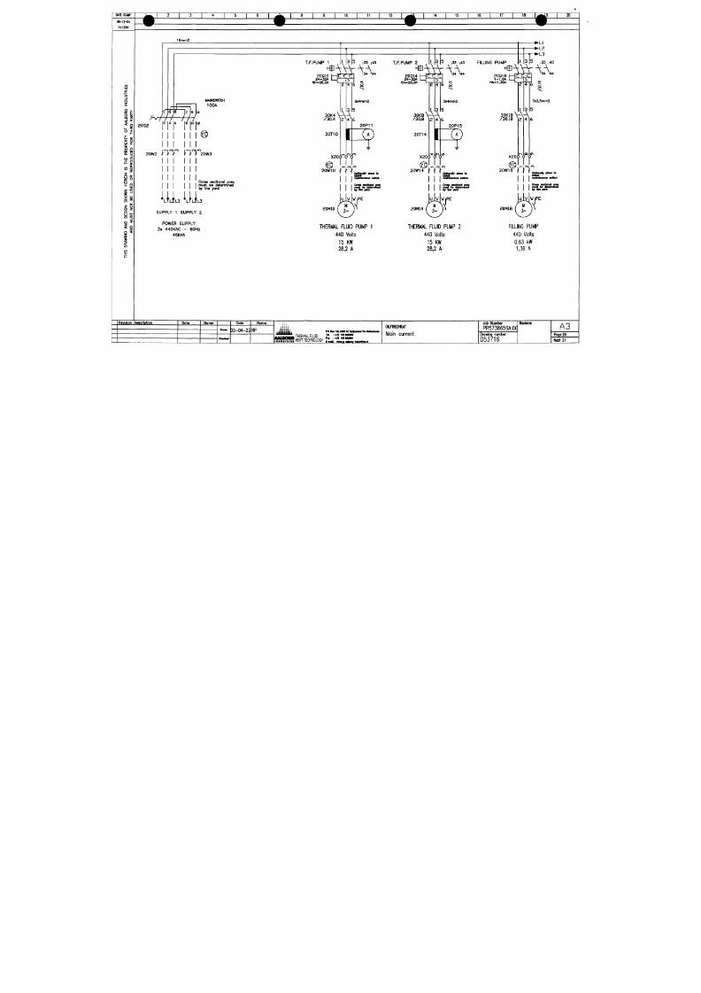
7/18/2019 M14 Thermal Fluid
http://slidepdf.com/reader/full/m14-thermal-fluid 51/486
13
3
O
O
L. £
UJ £
o.
o Q
o:
iij
o. u
« a
o:
o;
O
X
Q
o
1x1
S""
Z &
u z
ig
^i
C3
<
Z
i
Cl
w/
R;
/ •
?
MAINSWTTCH
100A
aos2
20W2
I
I I
H
@
I
rrr nr
20W3
I I I
I
I
I I
1 1 _ ^
I I must
IM
determinsd
1
I by
Crosa sectional
ana
•t
IM
dati
the yard
L3
SUPPLY 1 SUPPLY 2
POWER SUPPLY
3x 440VAC 60Hz
46kVA
T.F.PUMP 1
3 |5 ,33 ,43
20Q10
24-32A
lth-2a.2A
m^A
2 K | 6
S
30K4
/30
1 o
4 12 HI
20T10
I
X20<rö"ö'
3x4mm2
5
6
20P11
?
C M.ro
ppdgnaHy ploM
to
20W10
I I I
_
I I 1fnafeilMianM swHch
I
I I CreM ••oMcifKil ana
I l iy iL '^F'^
20M10
THERMAL FLUID PUMP 1
440 Volts
15 KW
28.2 A
T.F.PUMP 2
^
3 |5 ,33 ,43 FILLNG PUMP
20Q14 f— EIEJ
1—
l
4-32A
lth-28,2A
m ^ » ^ - ^
Tn6
s
30K8 V- \Ä
/30.8
20T14
I
X20<)'o"ö
3x4<nm2
20P15
?
20W14
i i Ir
< ' ' a p $ 2 « ^ P"«* <
I
I
I
I I Cro« —cttcyml ang
I
I
muit IM MunnrMd
I I by l lM yonl
20M14
THERMAL FLUID PUMP 2
440 Volts
15 KW
28,2 A
^
• L l
>L2
'L3
3 |5 33 43
20Q18 | —
1-1j6A I I />
^A
th-1.i6A
^^^
i
30K18 \ - \ A
/30.18 12141
X20p 9 9
3x2,5mm2
5
6
20wia i l l
OptSondty ploM
to
20M18
FILLING PUMP
440 Volts
0.63 kW
1,36 A
R ev is ion D aocr ipt ion
D o t e N o m e
D ot e
D5-04-25 RP
Nome
PO hül14&32aOM:
THERMAL FLUD "
[ ^ Z
dflREDHEAT
Main current
Job Number
PP5738659A.0q
D rawing num ber
Revson
A3
Poge
20
MIESTMP
06-12-04
t4:12:4S
IZZ
^ I 5 I 1 r
9 I 10 I 11 I 12 I
I 14 I 15 I 16 I 17 18
^ 9
I 20
L1
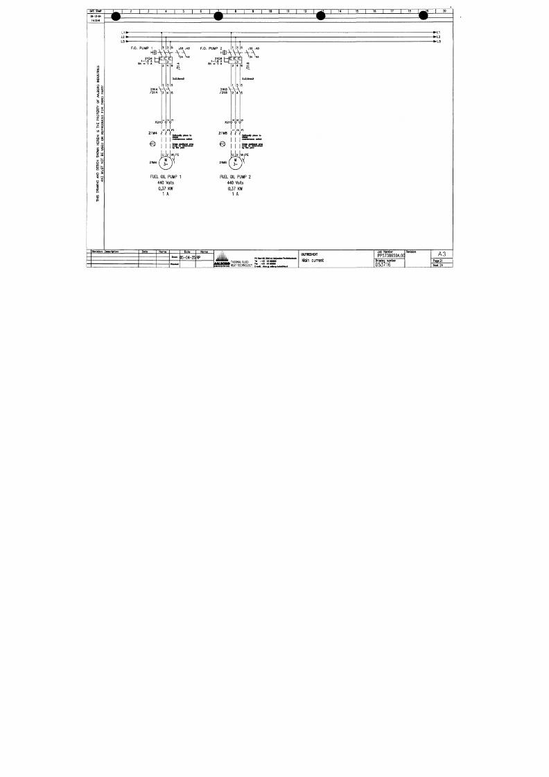
7/18/2019 M14 Thermal Fluid
http://slidepdf.com/reader/full/m14-thermal-fluid 52/486
i
O
o
O "^
uj £
o.
S o
CC Ul
o. o
UJ Q
M
Si
o:
tt: o
-^ UJ
•7
w
O UJ
S " "
o z
^1
O <
z
i
a
L1
L2
L3
»
•
F.O. PUMP 1
1
1
3 |a
|33 |43
F . O . PU M P 2 ,
1
1
' ' '
3
Is
|33 |43
».
•
L2
L3
^
21Q 4
1-1 "
Ith - 1 A
6
A I — 75
1 A I I. r. A •*.
2 4 6 -f
31K 4
/ 3 1 .
*V\A
4 1 2 H 1
X 2 i p Ö Ö
21W4 H I ,
I I I I»
D M
yird
21M 4
FUEL OIL PUMP 1
440 Volts
0,37 KW
1 A
^
21Q8 h—
1-1,6
K
I f />
m ^ « ^
4 6 r;
3x2,6fnm2
\ : \ - ^
1K 8
/31.8 12 14^6
X 2 1 6 Ö Ö
2iwa \ \ \
a>
OfnOftB^f pMOtt to
@
2 i M e
I
I
l _ _ ^
I
I I muBc bs oMflfi tw isa
I I l « l h >yvd
FUEL OIL PUMP 2
440 Volts
0.37 KW
1 A
Ravlslon Daacription Dote
Dot«
35-04-25
RP
Noma
iiiliiii«
-——* THERMAL FLUID
PO BMl«3I0OAC44|nkMllwlMtotaiA
T« •.*3t inuogoo
Fai :+ 3l intSOaOl
OimREDHEAT
Main current
Jo b
Number
PP5738659A.0a
D r a w i n g n u m b e r
Revision
A 3
Page
21
MTESrWP
06-12-04
14:12:45
W | 2 1 3 1 4 1 5 1 6 1
^ H CONmOL CURRENT 230VAC
^ ^
CDNTRDL C
4
1 8 1 9 1 10 1 11 1
t
24VAC
L I » f f
12 1 . ^ ^ 1 14 1 15 1 16 1 17 1 18 1 ,^ 9 | 20
9
9
• L I
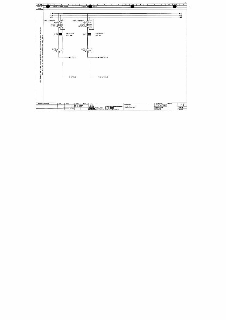
7/18/2019 M14 Thermal Fluid
http://slidepdf.com/reader/full/m14-thermal-fluid 53/486
a
^
(/)
a
z
<J
•>-
9 2
< Q
Li.
£
^ 0^
LU U.
O Q
o: iij
0 . U
3
Lij a
I - IE
« Si
o:
CC o
•^ Ui
i ^
o u
ä""
z 5
o 2
o s
? o
o <
2
i
o
n
L 2 *
CONT. CURRENT
a4Q3 1—C
1.6-2,5
1 -
24T3
^^'' A
*^>J?\
1 3
A
.
ci
c
/>
2 4
1
2
r
6
CONT. CURF
2
0 . 2 5 -
i E N T
*Q7
f - S
-0.4A 1
44 0/2 3 0V 24T7
630 VA
^
2 ^S <N V
4 ^
^
cl d,
i>
2 4
1
\
2
^
6
440/24VDC
100 VA
3
4
Revision Description
Date
Nama
Omwn
O m k «
Data
05-04-25
Noma
RP
^ I S I S L THERMAL FLUD I* =1? )2 2S?
0ILF1REDHEAT
Control current
•LS
Job Number
PP5738659A.0C
Drawing number
D53716
Revision
A3
Poge 24
Next 25
WiTESrWP
0 6 - 1 2 - «
14:12:40
i I 6
ANTI CONDENS HEATll
THERMAL FLUID PUMP
1
I 10 I 1
ANTI CONDENS HEATING
12
14 15
I 16 I
LAMP TEST
17
18 20
THERMAL auiO PUMP 2
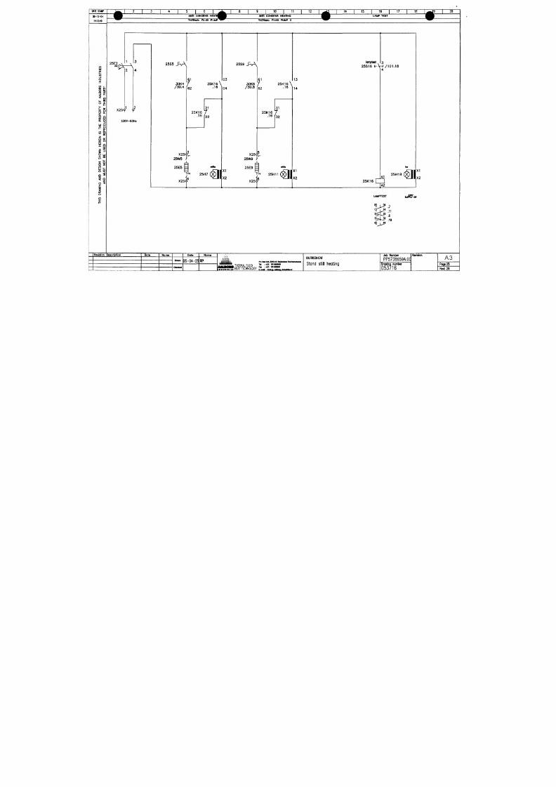
7/18/2019 M14 Thermal Fluid
http://slidepdf.com/reader/full/m14-thermal-fluid 54/486
o
o:
O
u- S
CO ilj
o uj
o
z
i
2 5 F 2
2A
^ 5 ^ '
X25<;)
1 <t^
230V-60HZ
2 5S5 _ R A
30K4 7
/30.4 f62
25S9 _F\A
2 5 K 1 6 \
.16
25K16 7
.16
I22
X25<jit
25W5
_L
25E5 =
03
04
30K8
/30.a 62
lamptest 3
25S16 E-V-//101.18
13
2 5 K 1 6 \
.16 V 4
hi
25K16 7
•16 f32
X25i'*
25H7
< ^ l
XI
X2
X25<j?.
25Wg
JL
25E9
=
y^
25H11
X25i^
XI
X2
AI
25H18
25K16
< a i
X,
1X2
M .
LAMPTEST
' ^ J ^ * .11
.b
.10
>|--?
Revision Deacription Dote
Nome
Dots
D5-04-25 RP
Noma
,i\Mu
THERMAL FLUID
HEAT TECHNOLOGY
PO • « m s a o A c
Tai
i-H)
181
Fai i-f» in
OILflREDHEAT
Stand still heating
Job Number
PP5738659A.0CI
Drawing nunnber
D53716
Revision
A3
Page 25
Next 29
O A I E S T W
0 e - 1 2 - ( K
10 12
14
15
16
E M E R G E N C Y
1 ^7 I 18-
20
S T D P
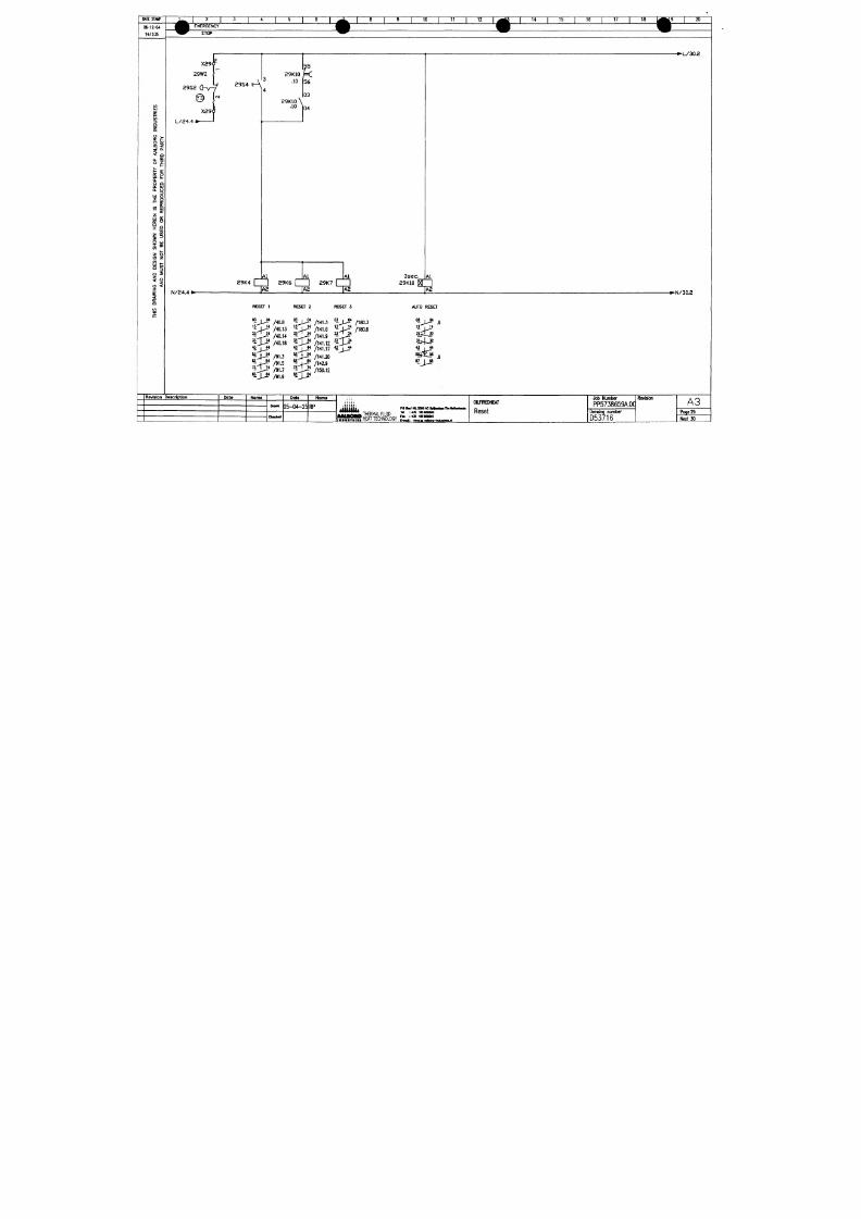
7/18/2019 M14 Thermal Fluid
http://slidepdf.com/reader/full/m14-thermal-fluid 55/486
UJ
i
o.
o
o:
o.
a
u
o
M Si
-^ ui
0 UJ
1 en
<n
i
X29
29W2
I;
2 9 S 2 ( H r - y
2 9 S4 E A
X29
L/24,4
I
Al
N/24,4
I
lAl lAl
29K4 I I 29K6
\ ~ \
29K7
\ ~ ]
^ Ä 2 ^ Ä 2 ^ Ä 2
•L /30 .2
3 s e c ^ l A l
29K10
WT
1^
••N/30.2
RESET 1
'^J^
/40.a
- J - ^ *
/40.13
" ^ ^ * /40.14
_ /40.18
/141.3
03
/iao.3
KP ^ /40M KP^
03
"J^*
/ H l 6
' - J - J - *
/ia0.6
^ • / 1 4 1 . 9 " - ^ *
Ain^O RESET
03 , 04
1.3
- - + ^
/91.5
^ 3 ^ *
/91.7
• ^ J ^
/91.9
/141.12
/141.17
/14U0
/142.9
/150.12
rpf-
2lji^
3 i4 ja
« j 4 *
«7 J J B •
R ev is ion D ascr ipt lon
D a t e
N o m a
D ot e
Q5-04-25 RP
Nome
THERMAL FLUID
P O l l e > t 4 & a o a « C 4 < | n m T l M l M l i i r i n *
n :43i isiaaiaoo
Fn i-^a tmaaosoi
OILFIREIMEAT
Reset
Job Number
PP5738659A.0CI
U rawing
Revision
A3
Poge 29
l
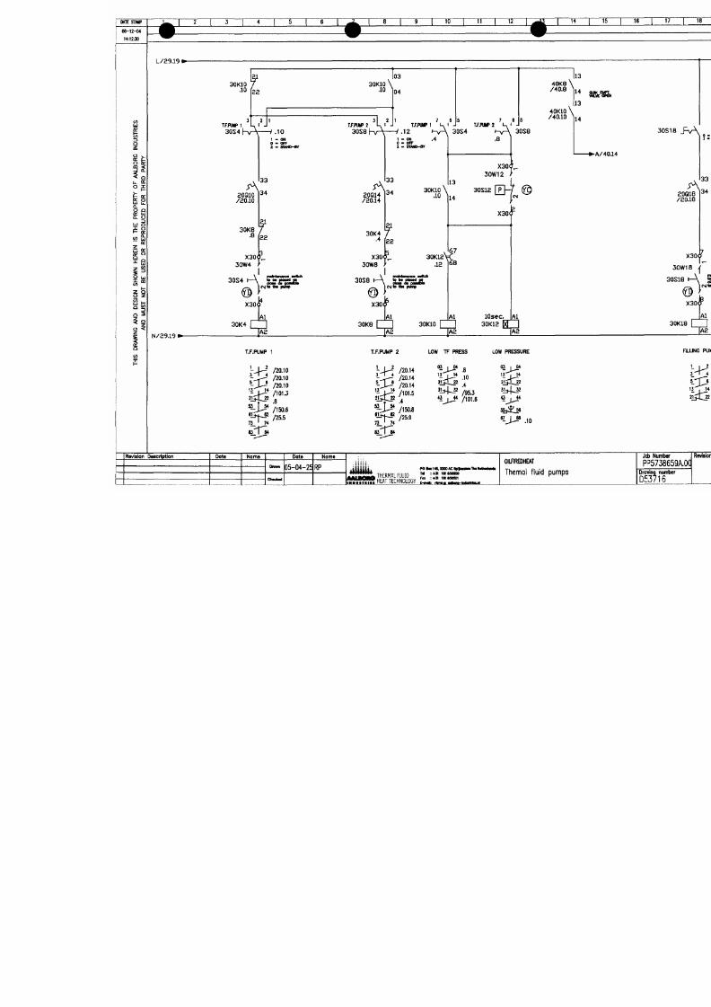
7/18/2019 M14 Thermal Fluid
http://slidepdf.com/reader/full/m14-thermal-fluid 56/486
t
"
i
S
r
(
x
^
o
A
(
V
J
O
O
s
0
-
^
•
H
^
^
"
1
1
1
^
1
°
I
"
i
"
-
Ö
0
X
o
i
-
ß
o
P
S
|
2
_
^
j
~
~
^
-
J
%
l
0
r
V
å
<
.
^
J
^
-
O
U
O
O
0
-
r
uO
n
K
l
^
S
o
o°
•
^
A
O
.
^
S
S
(
g
s
o
n
o
H
A
U
v
a
H
a
a
a
a
3
O
s
w
Q
N
V
s
a
s
N
o
w
3
A
a
3
H
S
N
I
3
M
3
H
N
M
O
H
S
N
s
Q
N
V
o
N
M
^
l
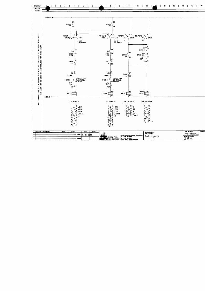
7/18/2019 M14 Thermal Fluid
http://slidepdf.com/reader/full/m14-thermal-fluid 57/486
O
t
o
S
l
I
B
-
<
^
O
K
—
s
^
r
s
V
r
—
^
^
1
^
5
l
O
0
©
i
A
C
d
C
A
ad
A
y
a
H
H
a
a
a
3
O
s
Q
s
y
s
N
o
o
w
o
A
y
3
H
s
N
H
NM
N
s
O
O
M
1
l
»
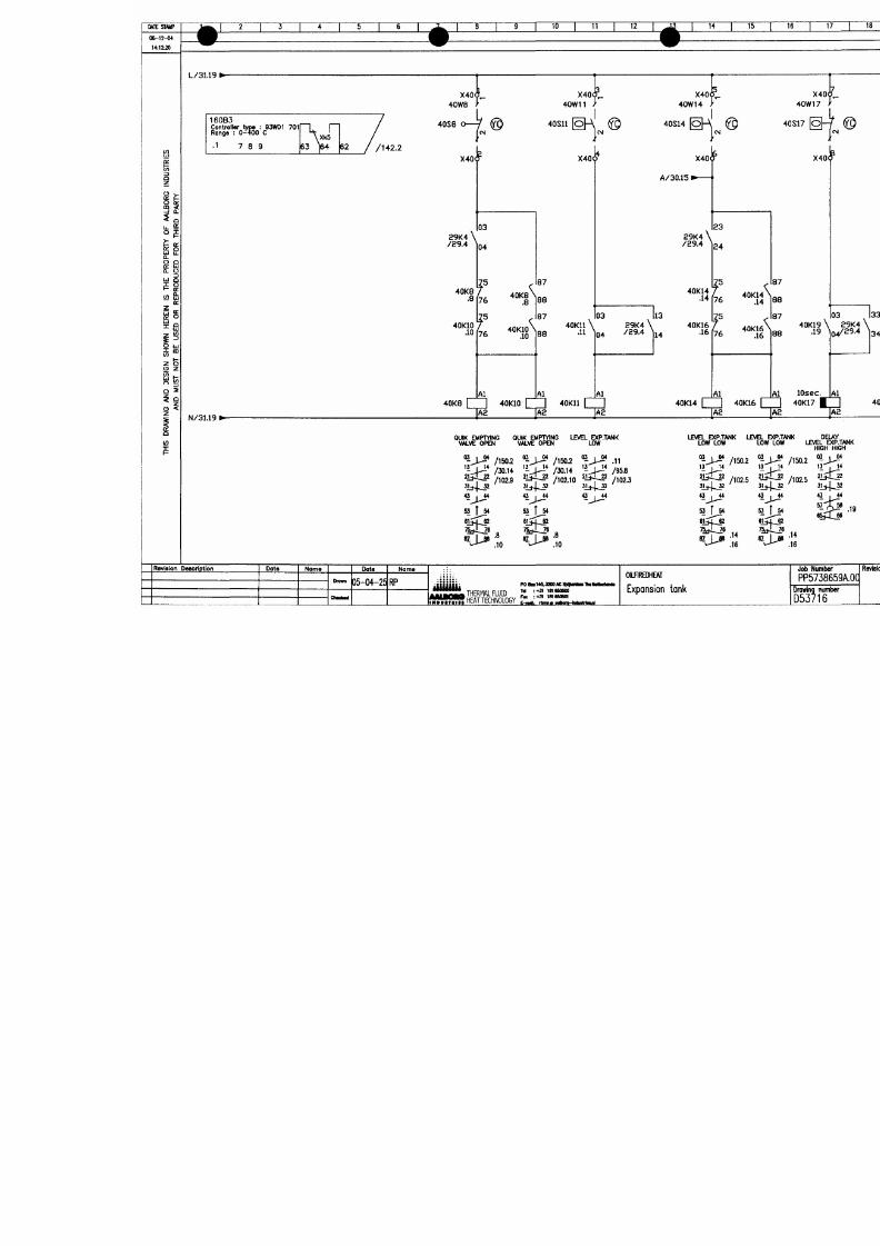
7/18/2019 M14 Thermal Fluid
http://slidepdf.com/reader/full/m14-thermal-fluid 58/486
O
^
5
1
o
o
5
i
5
'
i
æ
A
1
u
sX
r
~
,
_
^
n»
o
s
i
"
,
0
«
S
^
O
Q
:
0*
\
C<
•
o
<
>
f
mr
^
A
-
y
a
H
y
a
y
a
3
O
s
w
Q
N
V
s
y
s
N
o
w
J
O
A
y
3
H
s
N
3
H
N
W
O
H
S
N
s
Q
N
V
O
M
OME STAMP
06-12-04
14:12:16
CONTROL VALVE
OPEN CLOSE
" ^ T O P
10
I
11 I
12
14
15 16
T T
I 18
[~^^
I 2Ö"
lUPPLY
PERATURE
L/40.19i
•L/90.2
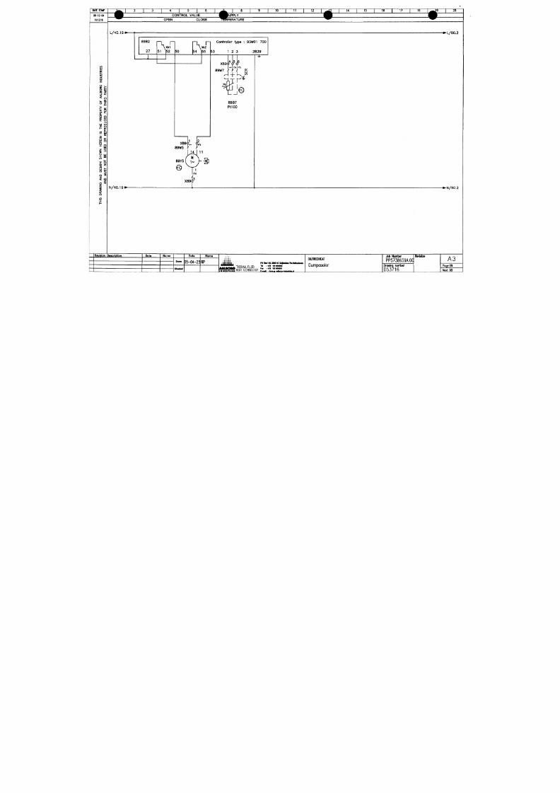
7/18/2019 M14 Thermal Fluid
http://slidepdf.com/reader/full/m14-thermal-fluid 59/486
I
o
a:
o
9
5
o
Q
Q: UJ
a. o
13
UJ a
>- Od
m
ui
QC
ÜJ _
I""
o
UJ
o z
is
O <
a9B2
27
\Xk1
51 ]52
5 0
Rv n
\Xk2
54 155
Controller type
:
93W01
700
153
1 2 3
2 8 2 9
N/40.191
89B7
Pt IOO
• N / 9 0 . 2
Revision Dascriptlon
Oats
No mo
Dots
D5-04-25
RP
Nome
po BKtAaiooM:
THERMAL FLUID
" =«i
i"« «»»o
HEAT TECHNOLOGY
Fax
r-MI
imaSOSOl
OILflREDHEAT
Dumpcooler
Job Number
PP5738659A.0q
Drowng number
D53716
Revision
A3
Page 89
Next 90
MTESMiP
06-12-04
14:1111
^ 1
2 1 3 1 4 1 5 1 6 1
^ B CONTROL VALVE
" ^ OPEN CLOSE
#
1
8 1 9 1 10 1 11 1
ESSURE
TWRNSMTTER
12
1 . ^2
1 14 1 15 1 16 1 17 1 18 1 . ^ 9 | 20
9
V
to
1
'0 1 ^
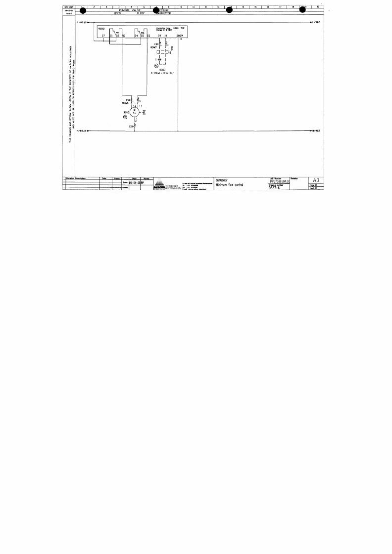
7/18/2019 M14 Thermal Fluid
http://slidepdf.com/reader/full/m14-thermal-fluid 60/486
a
(/>
3O
z
" •> -
tl^
K
o s
Ü. £
°g
ir o
Q.
O Q
o; UJ
0. U
=
J a
P ir
M S
or:
or: O
-^
UJ
i "
UJ
o z
Q
3
5 Q
O <
I
Ü1
f
90B2
37
1
r
r-
X k 1
51 ]
52 50
r\ n
X k 2
54
^55
Controllar type :93W01 70E
Ronga
0- 6 BAR
53 99 10 2829
X90(l <cM
90W7 ,
>
o:
1 1
t é
90B7
4-20nA 1 0-6 Bar
X9oL <L
90W5 > >
LiiJ '•'
goYs i~ V ^
.._ .B
X90<y
j .
Rflvision Description
Data
Nama
Dmm
Cliiri lK il
Data
05-04-25
Noma
RP
it iJ H it ; POaai14M200AC4>l]>nlMllMlMliirin4i
/HiJrZ.. THERMAL FLUD ™' ?15 25?
)GY ^ü ,;
r t n i v A o^BW"~«winii&nl
OimREDHEAT
Mnmum tlow control
Job Number
PP5738659A0]
Drowing number
D53716
Revison
A3
PoqeSO
Next 91
*
t
t
1
i
u
1
Æ
m
^
H
h
0
-
K
m
—
^
^
^
B
0
C _O I
r
o
^'
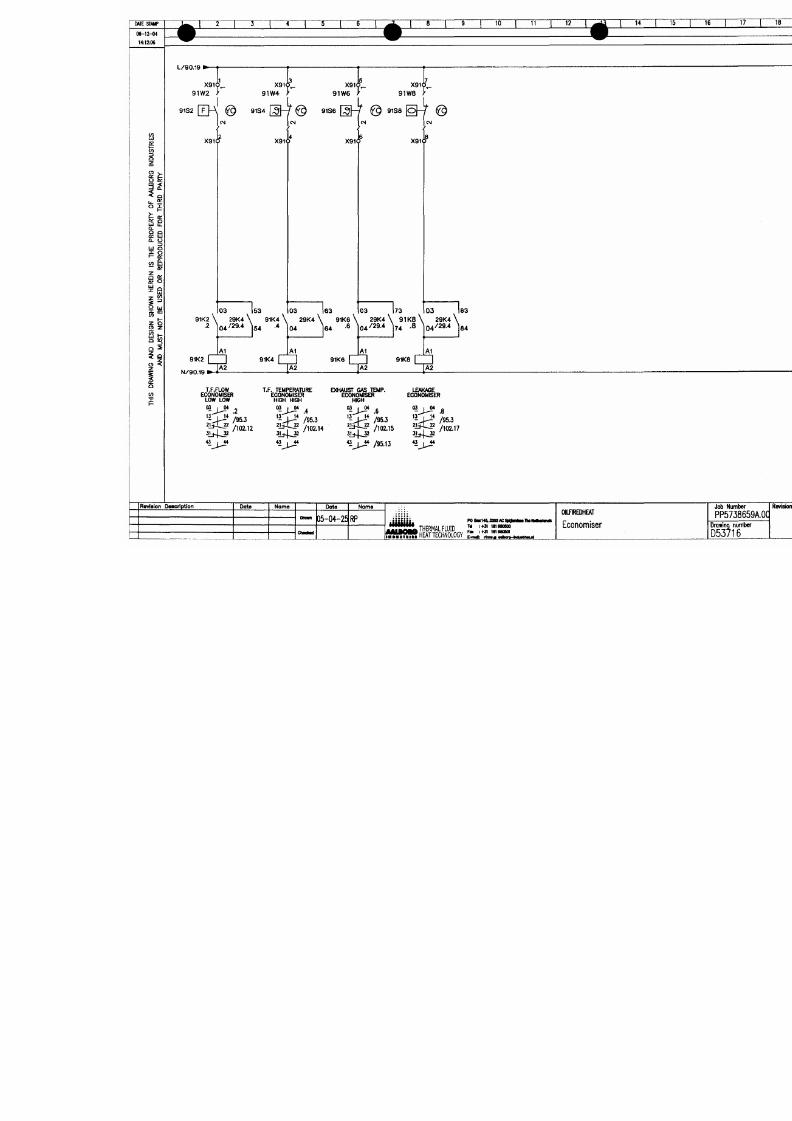
7/18/2019 M14 Thermal Fluid
http://slidepdf.com/reader/full/m14-thermal-fluid 61/486
W
I
N
A
D
G
S
W
N
H
N
S
T
H
P
O
A
I
N
E
A
M
N
B
zN
(
0
(
O
2
A
5
"
5
O
l
O
f
O
>
o
o
N
I
S
i
«
£
O
a
0
*
C
*
.
A
1
.
*
*
"
>
U
O
R
F
O
T
R
P
X
(
0
O
X
C
^
z
>
o
o
l
o
(
0
0
0
*
»
•
>
r
o
^
>
-
9
P
^
C
i
^
C
~
~
2
*
o
u
T
-
0
.
3
1
1
0
"
>
r
o
^
> -
^
o
o
*
O
J
^
0
"
1
°
s
O
o
5
Cro
-n
^
©
(O
to
»
io
^
©
(D
o
>
ä
^
©
C
C
O
0
^
1
^
©
rV S
,
n
°
2
i
s
-
_
—
~
'
T
—
L
~
C
^
g
—
•
^
-
o
—
:
^
°
C
(
O
J
_
•
^
°
^
^
C i
g
—
v
-
S
—
.
:
^
1
^
^
MI E STAMP
06-12-04
14:t2.-02
'^ T
10 12
I 14 I TS I Te" I 17 I 18
39 I 20
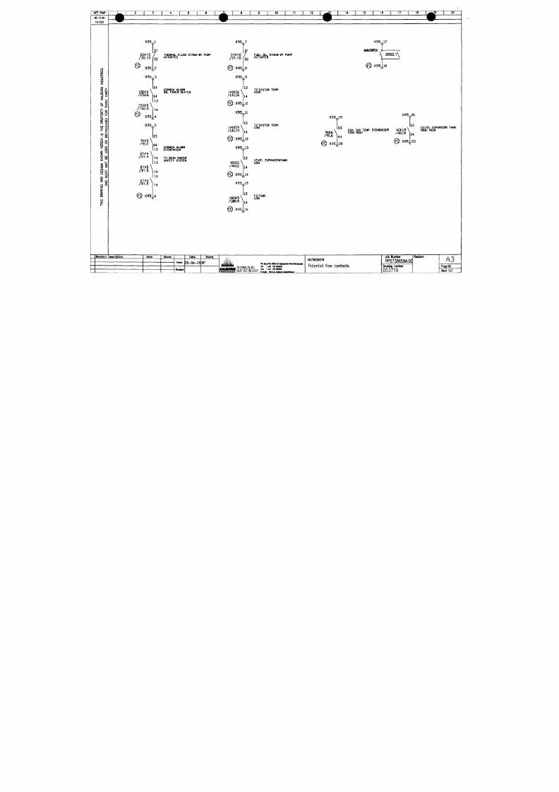
7/18/2019 M14 Thermal Fluid
http://slidepdf.com/reader/full/m14-thermal-fluid 62/486
£3
i
Lu ¥
o:
a
a. u
< n &
i'
< i
O <
i
to
X95 1
3 0 K1
/ 3 0 ,
(10 7
.10 I',.
X95
32
2
THERMAL FLUID STAND-BY PUMP
ACTUATED
X95 3
13
150K6
/150,6
150Ka\
/150.8 ^
@ X95
CDMMDN ALARM
DIL FIRED HEATER
14
113
14
4
X95 5
9iKa
/91,2
13
14
9 1 K4
/ 9
COMMON ALARM
13 CCONOMISER
••*
114 TO MAIN ENG INE
, SAFETY SYSTEM
X95 7
31K10
/31.10
f
32
@ X95j,8
X95 9
141K16 \
/141,16
13
14
@ X95J,10
X95 11
141K19 \
/141.19
13
14
@ X95j,12
X95 13
40K11 \
/40.11 ^
@ X95,
X 9 5
180K9
\
/180.9 ^
@ X95,
13
14
il4
f
13
14
[l6
FUEL O IL STAND-BY PUMP
ACTUATED
T.F.SYSTEM TEMP.
HIGH
T.F.SYSTEM TEMP.
LOW
LEVEL EXPANSIONTANK
LOV
F.O.TEMP.
LOV
X95 17
MAINSWITCH
20S2.1
^
@
X95Jjl8
X 9 5 Q 1 9
X95 21
13
91K6
/91.6
@ X95
4 3 \ LEVEL EX
\ EXH. GAS TEMP. ECONOMISER 40 K1 9 \ HIGH HIGH
\ HIGH HIGH
/4019 \ ^
@ X95
LEVEL EXPANSION TANK
44
20
14
22
Raviaion Deacfiptlon
Dote
Name
Pate
35-04-25 RP
Nome
Müh
THERMAL
FLUID
poBla14^^laoAc
n :+3i i n
OlLflRmEAT
Potential free contacts
Job Number
PP5738659A.0q
Drowinq number
Revision
A3
Poge 95
Next 101
MI E STAMP
0 6 - 1 2 - «
H:US
^
1
2 1 3 1 4 1 5 1 6 1
^ B
^ ^
L 2 4 V / 2 4 . a »
^ i ^
1 8 1 9 1 10 1 11 1 12 1 ^13 1 14 1 15 1 16 1 17 1 18 1
m m
F
^W
é
1 20
. ^ 4 V / 1 0 2 . 3
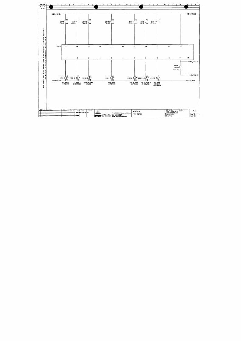
7/18/2019 M14 Thermal Fluid
http://slidepdf.com/reader/full/m14-thermal-fluid 63/486
u
o:
&i
13Cl
z
a:
C
° 5
< °
< o
Ü. £
O ^
0^
Q-
O Q
IK U
Q. O
r>
UJ o
f- o:
o: o
i -
2 S
O Z
2
^
a
X
Revislon
3 0 K 4 \
/ 3 0 . 4 1
101D3
13
3 0 K 8 \
1 4 / 3 0 . 8 ^
13
3 0 K 1 0 \
1 4 / 3 0 . 1 0 ^
43
4 4
13 14 15
1 2 3
X I
X I
X I
l O I H S ^ ^ " "
1 0 1 H 5 ( 5 ^ ' " 1 0 1 H 6 ( 5 ^ " '
N 2 4 V / 2 4 . 8 » •
| X 2 j X 2 ] X 2
T.F. PUMP 1 T.F. PUMP 2 STAND-BY PUMP
IN OPERATION IN OPERATION ACIUATH)
D e s c r i p t i o n
Dots
Norne
Dnnm
D a t e
05-04-25
Norne
RP
3 0 K 1 8 \
/ 3 0 . i a 1
13
3 1 K 4 \
1 4 / 3 1 - 4 ^
13
3 1 K 8 \
1 4 / 3 1 - 8
13
3 1 K 1 0 \
1 4 / 3 1 . 1 0 >
4 3
4 4
16 17 18 19 20 21
4 5 6 7 8 9
XI X I X I
X I
101H9 (X ) • " 101H12 0 * " 101H14 Ø *" 101H15 0 "*
1X2 |X2 TX2 J[X2
• t • •
nUJNG PUMP FU a OIL PUMP 1 FU a OIL PUMP 2 F.O. PUMP
IN OPERATION IN OPERATION IN OPERATION STANO-BT
IN OPERATION
å i i i i i t ; P O B i > i « ] 2 0 0 A C 4 iq M k a i i M iM i M i « < i
- Z I I U I I L
THERMAL FLUD If. :t2
12S2?
OllflREDHEAT
Pilot lamps
2 2 2 3
10 11
lamptest
2 5 S 1 6 - \
/ 2 5 . 1 6
3
4
Job Number
PP5738659A.0C
Drawing number
D53716
Revision
12
A 3
Poge 101
Next 102
MI E STAMP
0S-12-M
14:1132
J ^ 1
2 1 3
^ B
^ ^
L24V /101 .19 *
1 4 1 5 1 6 1 ^ 1 8 1 9 1 10 1
9
11 1 12 l ^ i 1 14 1 15 1
9
6 1 17 1 18 1
•
9 1 20
\
L24V/200.3
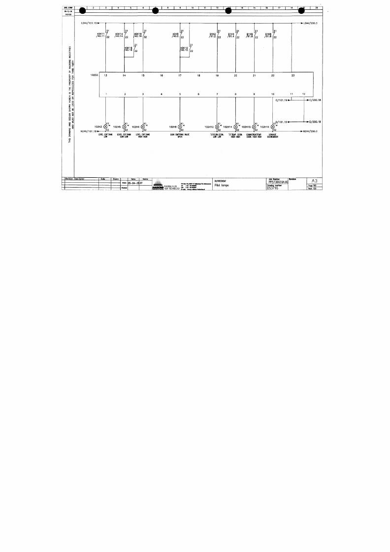
7/18/2019 M14 Thermal Fluid
http://slidepdf.com/reader/full/m14-thermal-fluid 64/486
K 3
i
a
z
'S V
Q.
O Q
o: u j
1 -
C£
m Si
o:
^ g
: o
O UJ
o z
< " l _
s§
1
i
f
Revision
40K11
/40 .11
102D3
7
22
13
1
102H3
^
N24V/101 .19» '
1
XI
yx2
40K14
/40 .14
f
22
40K16
'40.16
40K19
'40.19
r
22
f
32
14 15
2 3
102H5 6^
X I
h " 1 0 2 H 6 6
XL
1X2 TX2
fVE L EXP.TANK LE Va EXP.TANK LEVEL EXP.TANK
LOW LOW LOW HIGH HIGH
}escrip t ion
Dot«
Noma
Dmm
Chmod
Data
D5-04-25
Nome
RP
40K8
/40 .8
f
22
40K10
'40.10
f
22
16 17 18
4 5 6
102H9 6^
.XI
yx2
Q U I K E M P T Y I N G V A L V E
O P E N
j t H H i i ;
poBoiH«i32oo«sn»«*«n
A U Z M A THERMAL FLUID I* =* " 1?? ? ??
91K2
/91 .2
7
?1K4
'22 /91.4
7 91 KB
2 2 / 9 1 - 6
t /
19 20 21
7 8 9
102H12 (X
XI
?) 102H14 6
X I
h 102H15 6
1K8
91.8
7
2 2
22 23
10 11
XI
0 102H16 6
| X 2 y X 2 y X 2
T.F.aOW ECON. T.F.TEMP. ECON. EXHAUSTGASTEMP.
LOW LOW HIGH HIGH ECON. HIGH HIGH
OIlflREDHEAT
Pilot lamps
C/101.19
x f / 1 0 1 . 1 9
. 1
p<2
LEAKAGE
ECONOMISER
Job Number
PP5738659A.0C
Drawing number
Revision
12
2 0 0 . 1 8
^24V/200.3
A3
Paqe102
Next 120
DMESTW
06-12-04
14:11:47
I
g T
1
« I
I
'° r
12 14
I 15 I 16 I 17
18 J 9 20
L I
I
L 2 I
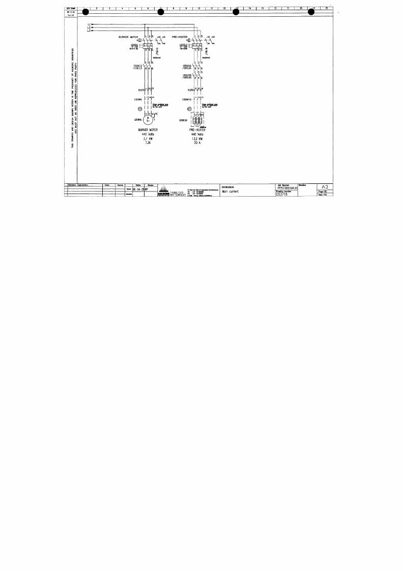
7/18/2019 M14 Thermal Fluid
http://slidepdf.com/reader/full/m14-thermal-fluid 65/486
&5
1=1
O
o:
o
o.
O
a
C H
lu
a. u
11 1 a
P o:
a:
X
Cl
tn
3
9 UJ
S""
o
z
5 9
i
L 3 I
BURNER MOTOR
. \ 3 ^ ,33 ,43
PRE-HEATER
6-
lth-7.3A
'
i
150K13 V-V Ä
/150,13 12 1416
X120<r<^<?
CraM Mcnonoi orM
I
t fmiM M Mnf nwwo
I i ir8i.xrt
120M6
BURNER MOTOR
440 Volts
3.7
KW
7,3A
^
1 3 5
|3 3
|43
120Q10 h-g
1 7 - 2 3 A
_ " 7>^
^-N-
2 4 6 -J
3)l2.aniin2
185K16V-\ ,
/185.16 ]2)4l6
185K18
\ - \ Ä
/ 1 8 5 . 1 8 1 2 1 4 1 6
in
>o
X120Ö Ö Ö
120W10
>'"]•>
I I
l Imu s t
am
OVH
120E10
PRE-HEATER
440 Volts
13,2
KW
20 A
Reviaion Daaeriptlon
Pote
Name
Dote
"^ D5-04-25RP
Name
- — • ^
THERMAL FLUID
HEAT
TECHNOLOGY
PO
B M I « ^
3200 AC y f iMi lMI
T4 :-tJI laSBQSOO
te i-f» laiHoaoi
OllilRmEAT
Main current
Job Number
PP5738659A.0a
Drawing number
D53716
Revision
A3
Poge 1 2 0
Next 141
l
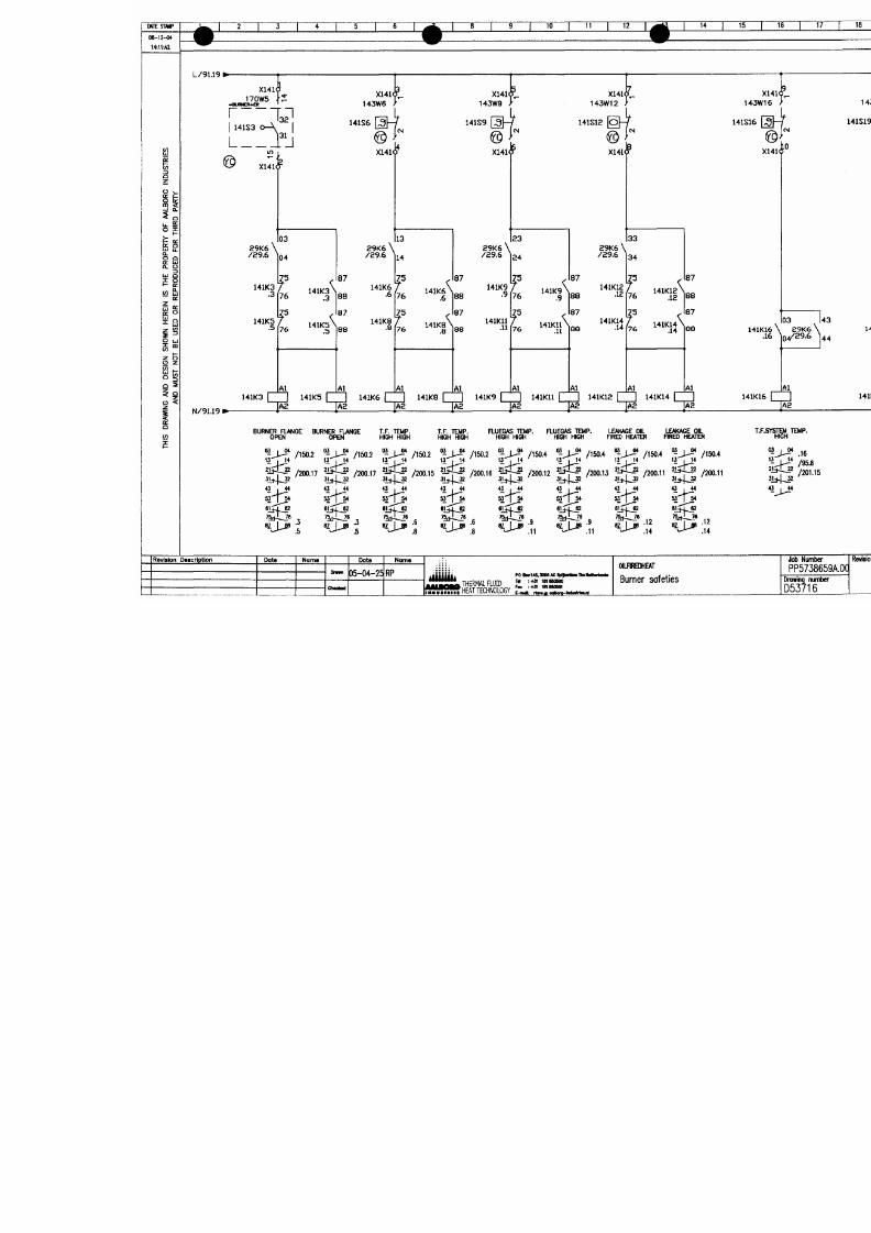
7/18/2019 M14 Thermal Fluid
http://slidepdf.com/reader/full/m14-thermal-fluid 66/486
_
-
o
U
J
^
a
o
^
C
o
X
2
w
-
O
U
-
«
2
o
X
s
t
o
^
©
^
-
A
*
^
2
•
X
o
S
"
I
s
I
v
D
O
r
^
0
(
^
0
0
0
0
0
-
f
i
n
v
i
n
v
O
C
•
^
^
^
r
^
0
N
0
0
æ
G
0
r
~
0
t
^
0
0
0
æ
0
C
V
J
1
L
—
i
w
-
T
O
A
y
a
H
y
o
a
a
a
3
O
s
w
Q
s
y
s
N
o
w
o
A
ü
3
H
s
N
3
H
NM
N
S
a
m
O
M
U
§
é
S
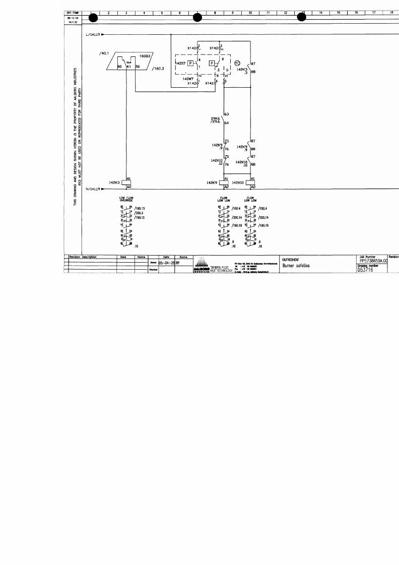
7/18/2019 M14 Thermal Fluid
http://slidepdf.com/reader/full/m14-thermal-fluid 67/486
C
0
C
^
•
e
s
o
•
^
y
O
2
^
•
O
C
^
o
o
i
£
.
*
^
S
^
o
o
—
c
^
<
^
•
<
1
—
n
o(
V
•
+
r
•
^
—
1
<
>
(
X
i
d
O
k
z
x
y
a
H
a
a
y
a
3
B
O
s
w
Q
s
y
s
N
o
B
w
JO
A
y
3
H
s
N
H
H
NW
N
O
S
O
Q
O
M
W1ESMff>
06-12-04
14:11J2
5
I 6"
^
]I3:
9
I 1° r
12
14
1~^
16
17 18
L/142.19 I
X150(
SPARE BURNER RELAY
TO BE
INSTALLED
|03 103
1S0B8
n2
20
• L / 1 5 1 , 2
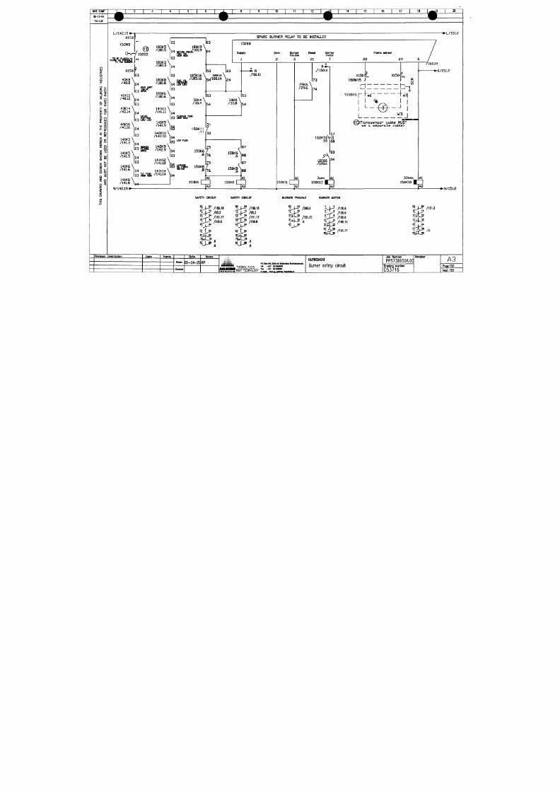
7/18/2019 M14 Thermal Fluid
http://slidepdf.com/reader/full/m14-thermal-fluid 68/486
3
O
o:
o
uj S
Q.
O Q
o:
Lj
o.
o
UJ
Q
I -
(E
2
fe
o:
a:
o
-^
ui
S""
o z
< ._
s§
^1
O <
z
i
Cl
150W6
I
C H r - y 1 5 0 S 2
180K5
\
/ 1 8 0 . 5
\
180K3
\
/ 1 8 0 . 3
^
180K9
\
P R E S S .
.9
X150O"
|03
4 0 K 8 \
/ 4 0 . 8
^04
03
40K10 \
/40.10 ^4
|03
40K14
\
'""''
104
04
Supply
Zsro
2
Bum«r
trouble
Rasat
21
Bumar
motor
Rama aanaor
2 2
24
W^'
180K8
/ 1 8 0 . 8
180K6
\
/ 1 8 0 . 6
\
04
|03
5 3
I
185K16
\
180K14
\
/185.16 ls/180,14 ^
2 3
2 4
3 0 K 4 \
/ 3 0 . 4
^
/40.14
40K16
\
/Arne \
0 3 LOW mv
/40,16 04
03
141K3 \
/141.3
^04
^
lo3
141K5 '
/141,5
141K11 \
/141.11 V4
103
141K9 \
/141.9 ]^^
142K10 \
/142.10 V4
^
|03
1 4 2 K 9
'
/ 1 4 2 , 9
1 5 0 K 1 1
.11
5 3
5 4
• * • R
/150.13
5 3
3 0 K 8 \
/ 3 0 . 8
^54
I
141K6 \
/in £. \
04
03
141K12
/141.12
/141.6
141K8
/141.8 \Q^
N/142,19
I
i V
04
03
JW^
141K14 \
/141.14
150K11
r
^ F l a n e s e n s o r c a b l e M UST
be
a
s e p a r o t e c a b l e )
.
57
1 5 0 K 1 8 V #
A
20Q6
/120.6
Al
3sec.
IAI
150K13
3 3
34
A2
S
3 s e c
JAI
15 K18
S
7160,14
•6/151,2
SAFETf CIRCUrr
'^-JJ /160.18
'KP* /95.3
K P ^ '
/151.17
" J ^ / 2 0 0 . 8
53 t 54
61513
SAFETY CIRCUIT
'^JJ^
/160.18
''-J^' /95.3
^Ji*
/ 1 5 1 . 1 7
KP / 2 0 0 . 8
M f 54
BURNER TROUBLE
BURNER MOTOR
03
I 04
2j5X,_a
43
, 44
/200.9
/151.17
' J - ^
/120.6
* /120.6
5
13 ' , 14
j5.
/120.6
' i
X - i '
/160.15
/151.17
03
I 04
2 l 3 X j 2
3 1 4 ^
«
j44
66
/151.3
.13
• N / 1 5 1 . 2
Ravlsion Oascription
Data
Noma Data
D 5 - 0 4 - 2 5 R P
N a m e
PO 801146^3200 AC
THERMAL FLUID
f l l ^ S S T
HEATTECHNOLOGY
E-mai; rt wa idhBfQ hdwMw jil
OIUnREDHEAT
B u r n e r s a f e t y c i r c u i t
Job Number
P P 5 7 3 8 6 5 9 A . 0 q
Drawing number
D53716
Revision
A3
Poge 150
Next
151
l
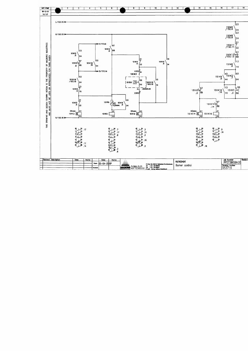
7/18/2019 M14 Thermal Fluid
http://slidepdf.com/reader/full/m14-thermal-fluid 69/486
o
<
0
^
dX
J
^
I
(
O
O
^
•
x
g
X
I
o0
o
s
<
t
o
V
C
O
i
S
o
s
V
C(0
1
C
o
ai
d
•
O
1
(
D
(
O
O
^
(
O
<
M
>
M
a
m
^
I
0
A
OÖ
1
N
Z
A
H
a
H
a
a
y
a
3
O
N
s
w
Q
N
V
S
y
s
N
o
w
JO
A
a
3
R
S
N
3
H
N
N
S
O
O
M
OME STAMP
ae-n-o*
14:11:22
BURMER OFF/ON SOMMOPQ R
12
U
15 16 17 18 20
dOSE/OPEN
L/151,19 I
•L/iso.a
/150.8
Burner relay LAL2.25
150B8
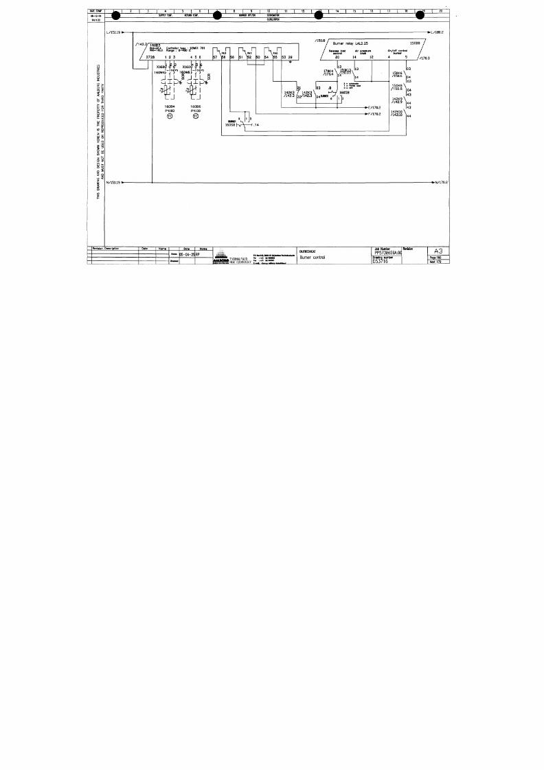
7/18/2019 M14 Thermal Fluid
http://slidepdf.com/reader/full/m14-thermal-fluid 70/486
a
O
ar
o
u. £
UJ £
O.
O Q
CH
t iJ
Q. O
o: o
o UJ
z o
u z
o
z
i
m
I
160B3
X k 4 - 4 0 . 4 C o n t r o l l a r t y p a : 9 3 W 0 1 7 0 1
X k S - 1 4 2 . 3 R o n g a : 0-4S5o C
2728 1 2 3 4 5 6
N/151,19 ^
X160
JfF^aeJW
160B6
P-tlOO
160B4
P-tlOO
BURNER
160S8 h v
> 1
R alaaaa load
c o n t r o l
20
Air pranura
chak
On/off control
bumar
14
12
170K4 \
/170 .4 >
21 |03
142K3 7 142K3 \
' '"^"^ (22/142.3 ^
13
150K13
/150 ,13
14
13
14
/ 1 4 2 . 3
.8
t - ^ 160S8
2 - A u t ono l l o
1 "
PtrtU
looil
O - OTF
g BURNER r
•E/170.2
•F/170.2
- / . 1 4
/ 1 5 0 ,6
' / 1 7 0 . 3
•N/170.2
R av is ion D ascr ipf aon
D a t e
N o r n e
D at a
D5-04-25 RP
N o m a
itm^fi
T H E R M A L F L U I D
H E A T T E C H N O L O G Y
poaKi4&]20OM:
U :+31 in
Fa» : 43 i innoaoi
O i m R E D H E A T
Bumer control
Job N um ber
PP5738659A.O0
D rawing num ber
16
D rawing r
D5371
R e v i s i o n
A3
P a g e 1 6 0
N ext 170
06-12-04
14:11:17
'2 T
/160.14
/
Burner relay LAL2.25
150B8
Bumer
in
operation
19
""8 T
10
I 11 I 12 ~ r
I 14 I 15 I
"W
17
"*
1 ^ ^ I °
Servomotor Feedback
opan
«Ignal
9
8
Servomotor Servomotor
cloae cloae
11 10
Nozzle* Ignition
traneformer
18 16
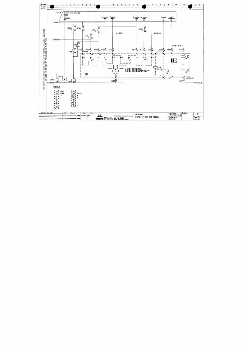
7/18/2019 M14 Thermal Fluid
http://slidepdf.com/reader/full/m14-thermal-fluid 71/486
i3
i
i
li . ^
°f
fe "^
O.
o
Q
o: uj
Q-
O
tt: < - >
-^
UJ
O Ui
S "
o
z
< " l _
S |
^1
O <
z
i
F/160.16
I
E/160,16
I
170P3
143
170K2 \ 170K4
.2
\AA .4
7
'32 170K4
\
.4
^
170K
170K4
\
87
A l
170K2
N/160.20
[
88
7 6
X170
r
170K4
,4
7
122
X170
03
04
X1706: X170
X170
170W5
2 7
12 8 129 114 112 til-
•H/151 .5
X170'
170K2
.2
f
22
L
X170'
W i l
t ^ ^
L_J
L_J
@
X170
iG/151 .5
IL
X170<
t
X170
M/151.19
t
I
\ I
L_J
L_J
15 13 16 JT ti
23
I
I
iE
I
Y15
CLGSE
I
-U MI T SWITCH ÜPEN
U = LIMIT SWITCH CLOSED
111 = LIMIT SWITCH IGNITION POSITION
VI I= LIMIT SWITCH PARTIAL LOAD
> ^
Y14
A l
]
i N
; ^ N i N
b T N
^\ _ /
j ^ _ y L j
^ |A2
j ~ ^
170K4~]Ä2
X170 X170
TM »BURNER+ER
3
•N/180.2
BURNER
IN
OPERATION
/200.3
' i J ^ "
/200.6
' ^
M
43 |_J4 4
BI^ TM
n _ ' 74
" j - i *
/160.14
2151122
g
^J^M^ is
M
| M
« l i T j E
Revieion Descfiption
Date
Norne
Date
D5-04-25 RP
Nome
iitiiitii
THERMAL FLUD " : ^
S S S f
HEAT TECHNOLOGY
c l ^ j ^ ^ r * "
OlREDHEAT
Burner air valve and nozzles
Job Number
PP5738659A.0CI
Drawing number
Revision
A3
Poge
170
Next 180
i
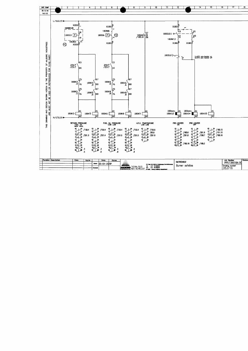
7/18/2019 M14 Thermal Fluid
http://slidepdf.com/reader/full/m14-thermal-fluid 72/486
I
i
n
n
<0
™
C
00
"
<
0
00
v
O
0
i
n
s
o
m
o
•
"
Vo0
«
«
X
If
1
i
A
,
=
2o0
5«
—
O
•
^
—
W
I
—
1
<
u
0
O
i
n
d
-
1
—
l
a
o
5
n
O
n
s
x
a
a
H
y
a
a
a
3
O
s
w
Q
s
M
i
s
N
o
w
o
A
a
3
S
N
3
H
N
N
s
Q
O
M
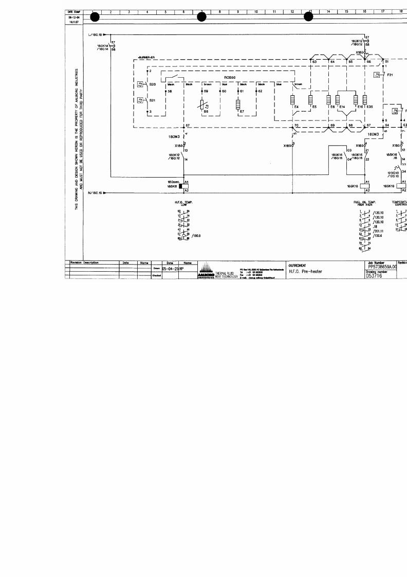
7/18/2019 M14 Thermal Fluid
http://slidepdf.com/reader/full/m14-thermal-fluid 73/486
•
O
O
)
é
O
cO
o
»
N
[
3
I
-
,
2
(
D
U
g
n
s
o
2
(
O
rI
c
1
n
^
^
J
I
^
n
I
I
L
_
"
z
J
L
«
7
f
?
J
s
p
j
g
l
i
o
A
a
a
H
a
a
a
a
3
O
N
s
w
Q
s
a
s
N
o
w
o
A
a
3
H
s
H
H
N
M
N
O
s
Q
o
N
M
MTE S TMIP
0 6 - 1 2 - 0 4
14:11:01
^ 1 2 1 3 1 4 1 5 1 6
^ ^
L 2 4 V / 1 0 2 . 1 9 »
0 3
13
^ ^ 1 8 1 9 1 10 1 1 1 i 12 1 ^ 1 1 4 1 1 5 1
^ H ^ H
^m ^^'
3 3 0 3
16 1 17 1 18 1
\
•
9 1 20
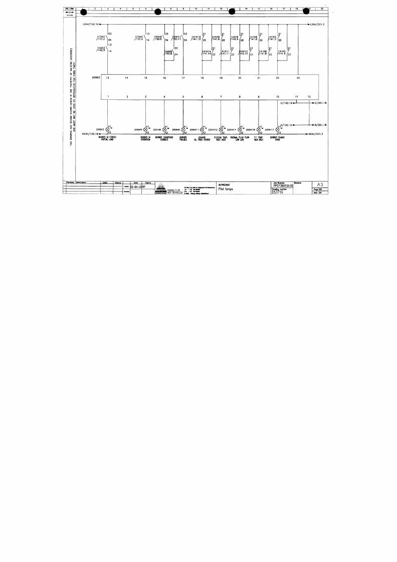
7/18/2019 M14 Thermal Fluid
http://slidepdf.com/reader/full/m14-thermal-fluid 74/486
^
3O
z
< 3 s .
O E
3 f
5 o
li.
e
uj Q
o Q
o:
i±i
Q. O
3
UJ Q
F= o:
</l UJ
o:
• ^ U J
i"
I m
( / )
1-
z o
o z
5 Q
§
z
£
o
en
Ravialon
1 7 0 K 2 \
/ 1 7 0 . 2 ^
1 4 2 K 3 \
/ 1 4 2 . 3 ^
2 0 0 D 3
1 7 0 K 2 \
0 4 / 1 7 0 . 2
13
14
1 4
13 14 15
1 2 3
X I
X I
2 0 0 H 3 ( X ) 2 0 0 H 6 ( X )
N 2 4 V / 1 0 2 . 1 9 » >
J X 2 ] X 2
BURNER IN FORCED BURNER IN
PARTIAL LOAD OPERATON
Description Data
Noma
Oman
O M C I X I
Data
D5-04-25
Noma
RP
1 5 0 K 6 \
/ 1 5 0 . 6 ^
/
1 5 0 K 8 \
'150.8
) 0 K 1 l \
50.11 ^
3 3
3 4
1 4 1 K 1 2
0 4 / l + L I Z
/
f
2 2
4 1 K 1 4
1 4 1 . 1 4
141K9
' 1 4 1 . 9
f ,
22 /
f
2 2
41K11
141.11
142K9
' 1 4 2 . 9
t
)
f
2 2
4 2 K 1 0
142.10
1 4 1 K 6
M 4 1 . 6
f
f
2 2
141
KB
2 2 , ' 1 4 1 . 8
16 17 18 19 20 21
4 5 6 7 8 9
X1 X I X I X I X I X I
141K3
' 1 4 1 . 3
' 1
2 2
T
2 2
141K5
' 1 4 1 . 5
I
2 2
2 2 2 3
10 11
C/102.19
. 1
0/102.19
^
A^
rd
2 0 0 H 8 ( X ) 2 0 0 H 9 ( X ) 2 0 0 H 1 1 ( X ) 2 0 0 H 1 2 ( X ) 2 0 0 H 1 4 ( X ) 2 0 0 H 1 5 ( X ) 2 0 0 H 1 7 ( X J
]X2 1X2 1X2 1X2 1X2 1X2
• • • I I «
BURNER CONDdONS BURNER LEAKAGE FLUEGAS TEMP. THERMAL FLUID FLOW T.F. TEMP.
CORREa TROU BII (XL RRED HEATER HIGH HIGH LOW LOW HIGH HIGH
j t i H i t i ;
poaaii4&aoo«c4i|MiiMiiMiMiiirin4i
y^JJJJpJL THFRMA Flllin ™ i « laieeoMo
OlfREDHEAT
Pilot lamps
T X 2
*
BURNER FIANGE
OPEN
Job Number
PP5738659A.0C
Drawing number
Revision
12
201.18
1
1
g 2 4 V / 2 0 1 . 3
A 3
Page 200
eC
^
M
0
.
9
S
CCC
1
*
^
^
t
d
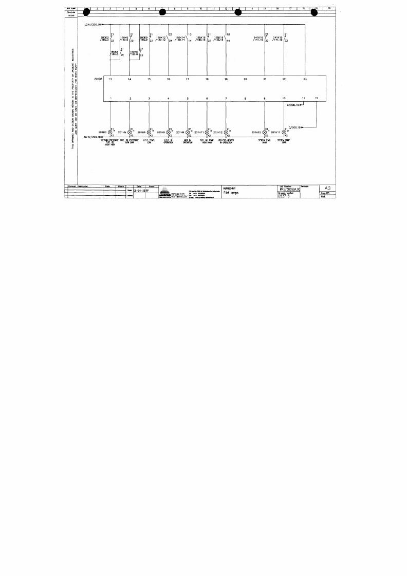
7/18/2019 M14 Thermal Fluid
http://slidepdf.com/reader/full/m14-thermal-fluid 75/486
V
W
e
A
9
jn
)VS
M
-
3
^HO
5
I
Z
C
Z
6
HH
d
^
^O
I
6
su
m
(s
d
m
d
»
uQ
a
HHH
NOHHQVG
fOH
^
(
I
^
i
3
9
t
,
\
9
9
,
\
,
\
3
J
6
6
8
8
3
3
1
9
9
S
9
C
C
C
i
U
D
5
5
S
Z
m
s
o
'
:
[
o
o
c
o
m
o
-
"
O
3
s
o
2
g
^
o
c
e
To a SAFE place
/ • " N i n t he at mospher e
25
I
PRESSURE INDICATOR
PRESSURE ALARM
PRESSURE CONTROLLER
PRESSURE TRANSMITTER
PRESSURE INDICATING CONTROLLER
TEMPERATURE INDICATOR
TEMPERATURE ALARM
TEMPERATURE CONTROLLER
TEMPERATURE TRANSMITTER
TEMP. INDICATOR CONTROLLER
FLOW INDICATING ALARM
IM I
MANUAL VALVE
IM I MANUAL VALVE N.C.
I^<1| MANUAL VALVE
"^ ' WITH LOOSE DISC
f^ MANUAL VALVE
WITH WELDING ENDS
^ MANUAL VALVE N.C.
WITH WELDING ENDS
|j<^|
MANUAL VALVE
WITH REGULATION DISC
1^1 MANUAL VALVE N.C.
WITH REGULATION DISC
<<>i MANUAL VALVE
^' ^ WITH REGULATION DISC
AND WELDING ENDS
^ MANUAL VALVE N.C.
' ^ WITH REGULATION DISC
AND WELDING ENDS
v < i M A N U A L V A L V E
WITH LOOSE DISC
AND WELDING ENDS
J _ ^ S E L F C L O SI N G
SOUNDING PIPE VALVE
• . BLOCKIN G VALVE
. ^ * S E L F C L O S I N G
Æk. FLAME ARESTOR
1^1 ELECTRIC TWOWAY VALVE
r/\ STRAINER
I m ) M A N U A L D R I V EN PU M P
_ ^ 3 \ _ E L E C T R I C D R I VE N P U M P
<
NON RETURN VALVE
"Z i lREDUCER
l y BELLOW
FILTER AIRREDUCER
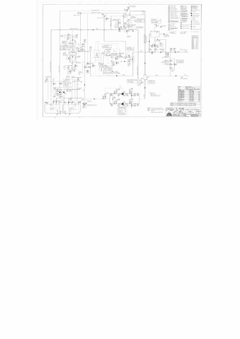
7/18/2019 M14 Thermal Fluid
http://slidepdf.com/reader/full/m14-thermal-fluid 76/486
PRESSURE DIFFERENTIAL SWITCH
INCL. VALVES AND ORIFICE
LEVEL INDICATOR
LEVEL ALARM
LEVEL CONTROLLER
TEMPERATURE TRANSMITTER
WITH DOUBLE ELEMENT
" " " " CAPILLARY TUBE
0 0 0 0 A I R - T U B E
ELECTRIC LINES
11^ SAFETY VALVE
P<i\ PNEUMATIC CONTROLED VALVE —
1 ^ 1 E L E C T R I C
3-WAY
VALVE '
) ^ _
6^
2-WAY
SOLENOID VALVE
3 - WAY SOLENOID VALVE
CALORIMAT
m\
ELECTRIC 2- WAY VALVE
I I XI I
THERMAL FLUD
STEAM
WATER
IIXII MECHANICAL CONTROL VALVE
L.C. = Loose Co ne
DN80
TO
HEAT CONSUMERS
200*0
PPE SIZING TABLE
ACQ TO ISO
OUTSDE
DN15
DN20
DN25
DN32
DN40
DN50
DN65
DN80
DN100
DN125
DN150
DN200
DN250
DN300
DAMETER
21.3
26.9
33.7
42.4
48.3
60.3
76.1
88.9
114.3
139.7
168.3
219.1
273.0
323.9
Min f l ow cont r ol
TYPE:
E l ect r i cal
acc. dwg 62050
150°C
^
FROM
HEAT CONSUMERS
YARD : J in l ing Shipyard
At : Nonjlng - P.R. of China
CLASS :
Germanischer Lloyd
+
MCE,AUT(SBG)
Aolborg
Project
PP5758659A.00
PP5738660A.00
PP5758661A.00
PP5758662A.00
PP5738841A.00
PP5758842A.00
052352-1
PP5739698A.00
052352-2
Newbuilding
JLZ04-0409 A
JLZ04-0410
A
JLZ04-0413 A
JLZ04-0414 A
JLZ04-0411 A
JLZ04-0412 A
JLZ04-0415 A
JLZ04-0416
A
JLZ04-0417 A
REMARK
A
REMARK A
Type EXV568-41-57.0-600 is used
dwgnr.
D53718
Type EXV660-43-57.0-600 is used
dwgnr.
054051
( 20M7
) For
electrical diagram
see DWG
D53716
ÖlT l
For
item number
see
fittingli st FITL5738659
Yard Delivery
For MDO/HFO diagram
see DWG
D53715
add new Fitno.
Hul numbers added
DESCRIPTION
AALBORG
NAME
PROJECTION
0 4 - 0 5 - 2 0 0 6
1 3 - 0 2 - 2 0 0 6
DATE
Thermal Fluid Diagram
DRAWN
CE
SCALE none
DAT 16-03-2005
DRAWING
No:
D53714
PO Bo 145,3200 AC Spienisse The Netherands
Id :+31 181650500
H E R M A L F L U I D
H E A T T E C H N O L O G Y ' ""
' • * '
'^'^'
REVSON
B
THIS DRAWING
AND
DESGN SHOWN
HERDN
IS THE
PROPERTY
OF
AALBORG
INDUSTRIES
AND
MUST NOT
BE
USED
SHEET
1
0 F 1
AI
in
D AIL Y
SERVICE
TAN K
MD O
PART OF MAIN
FUEL SYSTEM
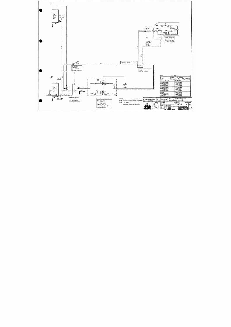
7/18/2019 M14 Thermal Fluid
http://slidepdf.com/reader/full/m14-thermal-fluid 77/486
S
115V
S e t p o i n t 8 Bar
rHTl—Ä-ff
0-6
Æ ]jiM n
^
DN
25
DISTANCE FROM DE-AERATORS TO BURNER
AS SHORT AS POSSIBLE
Oi l Pressure
Control ler
Type: FDR 20
A c e dw g . : D 00800
o<
ISSD
BURNER WEISHAUPT
Type RMS
7-ZMD
E-motor:
2.6 [kW]
E-heater: 13.2 [kW]
FUEL OIL DE-AERATOR
Size 2
Ace.
dwg D00799
DN 25
Y ARD :
J'mlbq
Shipyard
At : Nanjing - P.R. of China
CIASS : Germanischer Uoyd + MCE,AUT(SBG)
Aalborg Project
PP5738659A.00
PP5738660A.00
PP5738661A.00
PP5738662A.00
PP5738841A.00
PP5738842A.00
052352-1
PP5739698A.00
052352-2
Newbuilding
1204-0409
JLZ04-0410
JI204-0413
1104-0414
1.Z04-0411
1204-0412
JLZ04-0415
1204-0416
1.Z04-0417
Change Over Valves
Type:
PHD 40
Ace dwg. D42950
H.F.O. Circulating Pumps
Type:
ZAS 550
Cap.:
672 L/hr
H.: 2- 5 Bar(g)
E-Motor:
0,37 kW
Current: 3x440V -
Aec. Dwg. D00840
60Hz
QOMTJ For electrical diagram see DWG D53716
150031 For item number see fittinglist FITL5738659
E Ä R |
Yard Delvery
For System diagram see DWG D53714
R EV.
Hull Numbers added
DESCRIPTON
«iiliiiU
AALBORG
I N D U S T R I E S
PJ
NAME
PROECKN
€ 3
13-02-2006
D A T E
MDO / HFO Diagram
Modulating Burner
DRAWN CE
SCALE none
D A T E : 1 6 - 0 3 - 2 0 0 5
DRAWING No:
D53715
THERMAL FLUID
l ^ ' ^ l ^ ' S T A ' " ' " ' ^ '
HEAT TECHNOLOGY
^ - — ^ . ^ . ^
R E V I S I O N
DB MUWK AW DESm SHOW
WREn
rS
1HE PROFERY
OF
At i ra»
MUSnss MB HSr NOT
S
USED
Bv 01
t E m o n x a
F O R D M I P A RT Y
SHEET
1
0 F1
A2
ALUVEILER
7/18/2019 M14 Thermal Fluid
http://slidepdf.com/reader/full/m14-thermal-fluid 78/486
Operating and Maintenance Instructions
VM No.:
Edition:
Ident No.
460.0008 GB
07.01
55 0 102
Volute-Casing Centrifugal Pumps
Series NTT and CTT
Retain
for future
use
Order No.:
Machine No.:
Pump Ident. No.:
Pump Type:
Operating
data,
dimensions and other additional information can be found in the order-specific part of the
documentation.
A
hese Operating and Maintenance
Contents
1.
General
7/18/2019 M14 Thermal Fluid
http://slidepdf.com/reader/full/m14-thermal-fluid 79/486
NTT/CTT ALLWEILER
1 General
1.1 Pu mp designation
The exact designat ion ca n be found In the order-sp e
cif ic documents (see data sheet).
1.2 Properuse
Information on proper use of the pumps is provided in
the technical data sheet.
The pumped l iquid must not contain any abrasive con
stituents nor corrode the pump materials.
1.3 Pe rforman ce data
The exact p erformance data can be taken from the or
der data sheet and/or acceptance test report.
1.4 Warranty
Our warranty for shortcomings in the supply is laid
down in our delivery co ndit ions. No l iabil i ty wil l be un
dertaken for damages caused by non-compliance with
the operating instructions and service condit ions.
If at any later date the operating co nditions cha nge (e.g.
different f luid co nvey ed, sp eed , viscosity, tempe rature
or supply condit ions), i t must be checked by us from
case to case and confinned , if necessary, that the pum p
is suited for those purposes. Where no special agree
ments were m ade, pump s suppl ied by us may, dur ing
the wan-anty period, only be ope ned or varied by us or
our authorized c ontract se rvice wori<shops; otherwise
our l iabil ity for any de fects w il l cease.
1.5 Testing
NTT/CTT
ALIWEILER
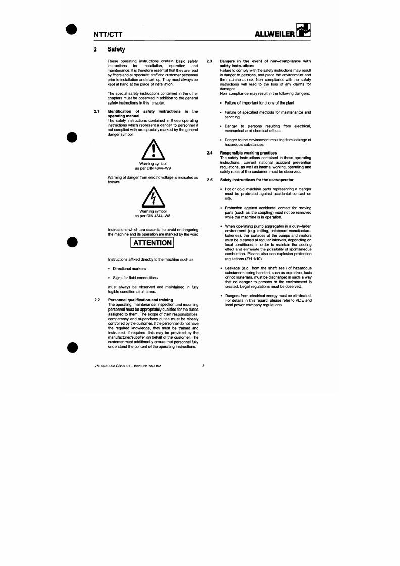
7/18/2019 M14 Thermal Fluid
http://slidepdf.com/reader/full/m14-thermal-fluid 80/486
2 Safety
2.1
These operating instructions contain basic safety
instnjctions for installation, operation and
mainten ance. It is therefore essential that they are read
by fitters and all specialist staff and cus tome r pe rsonnel
prior to installation and start-u p. They m ust always b e
kept at hand at the place of installation.
The special safety instructions contained in the other
chapters must be observed in addit ion to the general
safety instructions in this chapter.
Identification of safety instructions in the
operating manual
The safety instmctions contained in these operating
instmctions which represent a danger to personnel if
not complied with are specially marked by the general
danger symbol:
Warning symbol
as per DIN 484 4-W9
Wam ing of danger from electric voltage is indicated as
follows:
2.3 Dangers in the event of non-co mplian ce with
safety instructions
Failure to comply with the safety instructions may result
in danger to persons, and place the environment a nd
the machine at r isk. Non-compl iance wi th the safety
instructions wil l lead to the loss of any claims for
damages.
Non -comp l iance may resul t in the following dangers:
• Failure of important functions of the plant
• Failure of spec if ied metho ds for maintenance an d
servicing
• Danger to persons result ing from electrical,
mechanical an d chemical ef fects
• Danger to the environment result ing f i-om leakage of
hazardous substances
2.4 Responsible working practices
The safety instructions contained in these operating
instmctions, current national accident prevention
regulations, as well as intemal working, operating and
safety rules of the customer, must be observed.
2.5 Safety instructions for the user/operator
• Hot or cold machine parts representing a dan ger
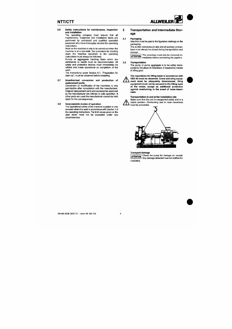
7/18/2019 M14 Thermal Fluid
http://slidepdf.com/reader/full/m14-thermal-fluid 81/486
NTT/CTT
ALLWEILER
2.6 Safety instructions for maintenance, inspection
and installation
The operating company must ensure that all
maintenance, inspection and installation tasks are
performed by authorized and qualif ied specialist
personnel who have thoroughly studied the operating
Instructions.
Wort< on the m achine Is only to be carried out when the
machine Is at a standsti l l . The procedure for shutting
down the machine described In the operating
Instructions must always be followed.
Pumps or aggregates handling f luids which are
detrimental to health must be decontaminated. All
safety and protective devices must Immediately be
refitted and made operational on completion of the
work.
The Instnjctlons under Section 6.1 , "Preparation for
start-up", must be observed before restarting.
2.7 Unauthorized conversion and production of
replacement parts
Conversion or modification of the machines Is only
permissible after consultation with the manufacturer.
Original replacement parts and accessories approved
by the manufacturer are intr insic to safe operation. If
other parts are used the manufacturer cannot be held
liable for the consequences.
2.8 Unacceptable mo des of operation
The ope rational safety of the machine su pplied Is only
ensured w hen it Is used In accordance with Section 1 o f
the operating instructions. The l imit values given on the
3.1
Transportation and Intermediate Stor
age
Packaging
Attention m ust be paid to the f igurative markings on th e
packaging.
The suctk)n and pressure side an d all auxil iary con nec
tions must always be closed during transportation an d
storage.
The cover ings must only be removed im
mediately before connecting the pipeline.
3.2
A
A
A T T E N T I O N
Transportation
The pump or pump aggregate Is to be safely trans
ported to the place of Installation, if required by mean s
of lifting gear.
The regulations for lifting loads in accordance with
VBG 9a must be observed. Crane and sling equip
ment must be adequately dimensioned. Sling
equipment m ust not be secured to the lifting eyes
of the motor, except as additional protection
against overturning in the event of nose-heavi
ness.
Transportation to and at the Installation site
Make sure that the unit Is transported safely and In a
stable posi t ion. Overtuming due to nose-heaviness
must be prevented.
NTT/CTT
ALIWEILER
7/18/2019 M14 Thermal Fluid
http://slidepdf.com/reader/full/m14-thermal-fluid 82/486
3.3 P reservation / Storage of centrifugal pump s
3.3.1 Preservation
In the case of storage or prolonged standsti l l , the
pumps must be protected against corrosion. In those
cases , an outside and inside preservation is to be pro
vided. The durabil i ty of the protection against corro
sion, which is l imited in time, depends o n the com posi
t ion of the preservative to be applied and the storage
condit ions.
Under normal ci rcumstances the pumps
have no special preservative.
T T E N T I O N
At an addit ional charge we can, however, supply
pumps and replaceme nt parts ex factory with a preser
vative adequate to the planned storage period.
3.3.1.1
Outside preservation
The outside preservative should be app lied by painting
or spraying with a spray gun .
Po ints of preservation:
All bright and unvamished parts (e.g. shaft ends, cou
pl ings, f lange facings, valve and m anometer connec
tions).
3.3.1.2 Inside preservation
(Not required for pum ps made of stainless materials.)
Intemal preservation is applied by painting, spraying
using spray
guns,
f i ll ing/dipping and s ubseq uent drain
i n g . Finally, the suction and outlet branch es as well as
all other supply and discharge branches must be
A
Note: The preservatives l isted are to be regarded as a
recommendation. Altematively, technically equivalent
products from other manufacturers can be used.
When handling preservatives, the safety hints con
tained in the relevant DIN safety data sheets and thos e
of the manufacturer must be complied with.
3.3.1.4 Depreservation
Prior to sett ing the pum p in mo tion, the inside preserva
t ion must be removed.
A
Environmentally compatible disposal must be en
sured.
Preservatives can be removed wi th wax solvents, pe
troleum ether, diesel, petroleum or alkaline cleaners.
However, the simplest method is to use a steam clean
er.
Recommendation for Tectyl 506 EH: Al low petro
leum ether to act for 10 minutes before any further ac
tion.
A
Pumps that are used in the food or drinking water sector
must be dism antled and thoroughly cleaned prior to de-
preservatk)n.
A suitable so lvent that is compatible with the liqukj to
b e
pumped (dr inking water / food) can be used as the
cleaning age nt, e.g. Spiritus, Ritzol 155 or suds with a
high alkaline content. Steam cleaning is ideal.
A T T E N T I O N
After a prolonged storage period (more
than 6 months) , al l elastomers (O-r ings,
shaft seals) must be checked for elasticity of shape.
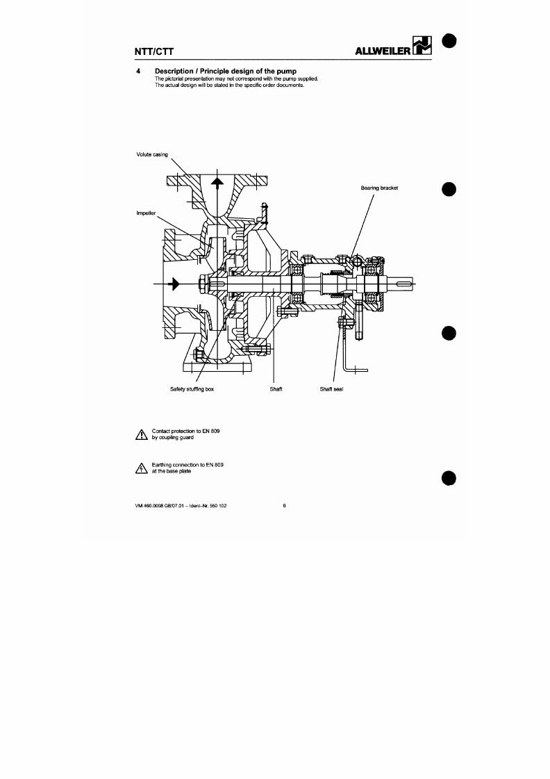
7/18/2019 M14 Thermal Fluid
http://slidepdf.com/reader/full/m14-thermal-fluid 83/486
NTT/CTT
ALLWEILER
4 Description / P rinciple design of the pum p
The pictorial presentation may not correspond with the pump supplied.
The actual design wil l be stated in the specif ic order documents.
Volute casing
Impeller
Bearing bracket
NTT/CTT
ALIWEILER
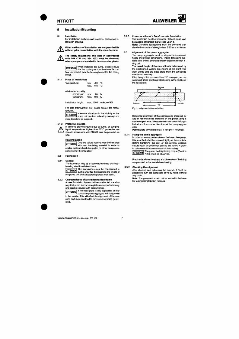
7/18/2019 M14 Thermal Fluid
http://slidepdf.com/reader/full/m14-thermal-fluid 84/486
Installation/Mounting
5.1
A
A
Installation
For installation methods and locations, please see in
stallation drawing.
Other m ethods of instal lation are not pe rmissible
without prior consultation with the m anufacturer.
The safety regulations and tests in accordance
with DIN 4754 and VDI 3033 must be observed
where pumps are instal led in heat-transfer plants.
5.2.3
A H E N T I O N
When install ing the pump, please ensure
that the cooling air from the mo tor fan can
flow unimpede d over the bearing bracket to the casing
cover.
5.1.1 P lace of Installation
Temp erature: min . -2 0 °C
max. +40 °C
relative air hum idity:
permanent max. 85 %
temporary max . 100 %
Installation height: max. 1000 m abo ve NN
For data differing from this, please consult the manu
facturer.
Intensive vibrations in the vicinity of the
T T E N T I O N
5.3
Characteristics of a floor/concrete foundation
The foundation m ust be horizontal, f lat and clean, and
be capable of b earing the full load upon it.
Note:
Concrete foundations must be executed with
standard concrete of strengfl i das s B 25 as a minimum.
Alignment of the pump aggregate
The pump aggregate must be al igned to i ts pre-set
height and system dimensions. This is done using
s u i
table steel shims, an-anged direcfly adjacent to each f i
xing bolt.
The overall height of the steel shims is determined by
the established system dimensions of the plant. The
steel shims and the base plate must be posit ioned
evenly and securely.
If the fixing holes are more than 750 mm apart, we re
comme nd fitt ing addit ional steel shims in the middle of
the base plate.
Baseplate
a
7L T.
V
F i g . 1 : Alignment
with
steel shims
NTT/CTT
ALLWEILER
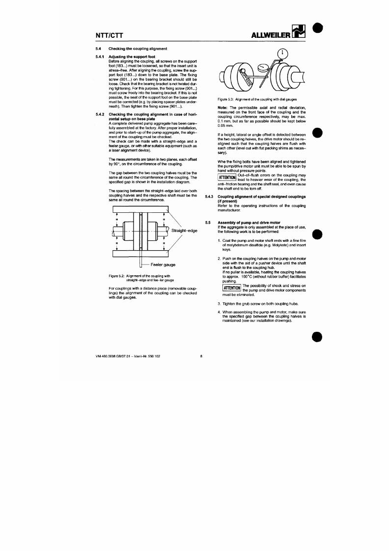
7/18/2019 M14 Thermal Fluid
http://slidepdf.com/reader/full/m14-thermal-fluid 85/486
5.4 Checking the coupling al ignment
5 .4.1 Adjusting the support foot
Before aligning the coupling, all screws on the sup port
foot (183...) m ust be loosened, so that the insert unit is
stress -free. After aligning the coupling, screw the sup
port foot (183...) down to the base plate. The fixing
screw (901...) on the bearing bracket should sti l l be
loose.
Che ck tha t the bearing bracke t Is not twisted du r
ing tightening. Fo r this purpose, the fixing screw (901...)
must SCTew free ly into the bea ring b racket. If this is n ot
possible, the se at of the support foot on the base plate
must be corrected (e.g. by placing spacer plates under
neath). Then tighten the fixing saew (901...).
5.4.2 Checking the coupling al ignment in case of hori
zontal setup on base plate
A complete delivered pump aggregate has t)een care
fully ass emb led at the factory. After proper Installation,
and prior to star t-up of the pump a ggregate, the al ig n
ment of the coup l ing must be checked.
The check can be made wi th a straight-edge and a
feeler gauge , or with other suitable equipment (such as
a laser alignment device).
The measurements are taken in two planes, each offset
by 90°, on the circumference of the coupling.
The gap between the two coupl ing halves must be the
same all round the circumference of the coupling. Th e
specif ied ga p is shown In the installation diagram .
Figure 5.3: Alignment of the coupling with dial gauges
Note: The permissible axial and radial deviation,
measured on the front face of the coupling and the
coupling circumference respectively, may be max.
0.1 mm, but as far as possible should be kept below
0.05 mm.
If a height, lateral or angle offset is detected betwee n
the two coupling halves, the drive motor should be re
aligned such that the coupling halves are f lush with
each other ( level out with f lat packing shims as ne ce s
sary).
Whe the fixing bolts have been aligned and tightened
the pump/drive motor unit must be able to be spun by
hand without pressure points.
Out-of- f lush errors on the coupl ing may
lead to heavier wear of the coupling, the
T T E N T I O N
anti-fr ict ion t)earing and the shaft
seal,
and even cause
NTT/CTT
ALIjyVEILER
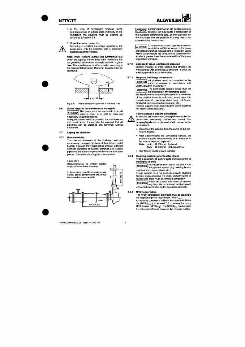
7/18/2019 M14 Thermal Fluid
http://slidepdf.com/reader/full/m14-thermal-fluid 86/486
A
5.6
5. In the case of horizontally mou nted pump
aggregates f ixed on a base plate or directly on the
foundat ion, the coupl ing must be al igned as
described in Section 5.4.
6. Mount the contact protection.
According to accident prevention regulations, the
pump must only be operated wi th a protect ion
against accidental contact.
Note: When install ing pumps with symmetrical feet
which are supplied without base plate, make sure that
the gu ide bolt at the volute cas ing is seated In a guide
hole. Th e hole diameter must be provided according to
the representation below. The 5 mm distance must be
observed.
A T T E N T I O N
F i g . 5.4: Volute casing with guide bolt in the base plate
Space required for maintenance and repair
The pump must be accessible from all
sides in order to be able to cany out
H E M T I O N
necessary visual inspections.
Shorter pipelines on the suction side are
possible, but may lead to a deterioration of
the hydraulic performance data. Shorter pipelines on
the discharge side are possible, but may lead to in
creased noise developmen t.
A T T E N T I O N
Compensators must not generate any un
acceptable addit ional forces on the pump
connection branches. Special care is needed in cases
where compensators are used, whose pressurised di
ameter is greater than the nominal width of the pump
connect ion branches.
5.7.2 Changes in cross-s ection and direction
Sudden changes in cross-sect ion and direct ion, as
we ll as bends with a bend radius less than 1.5 times the
interior pipe width, mus t be avoided.
5.7.3 Supports and flange connections
All pipelines must be connected to the
pump stress- f ree in accordance wi th
T T E N T I O N
VDM A standard sheet 24277.
The permissible pipeline forces must not
be exceeded in any operating status.
T T E N T I O N
We therefore recommend on principle that a calculation
of the pipeline forces is performed, which takes into
consideration all operating status (e.g. cold/warm,
empty/full , depressurised/pressurised, etc.).
Pipeline suppo rts mu st always be free sIkJing and m ust
not rust in (check regu lariy).
How to assess a pipel ine conn ection
To conduct an assessment, the pipeline must be de-
NTT/CTT
ALLWEILER
7/18/2019 M14 Thermal Fluid
http://slidepdf.com/reader/full/m14-thermal-fluid 87/486
5.7.6
A T T E N T I O N
The applicable NPSH values in the char
acteristic curves a re for water with 20 ° C .
For other med ia and/or temperatures, the NPSH value
may deviate from the cha racteristic curves.
A T T E N T I O N
Uncertainties in the determination of
NPSH condit ions, particularly for media
other than water and/or other temperatures, must be
compensated for by increased safety factors (please
consult the ma nufacturer).
Inlet pipeline
In order to avoid the formation of air bags, the inlet
pipeline m ust be laid rising to the pu mp.
5.7.6.1 Stop valve (inlet mode)
A stop valve is to
b e
installed in the inlet pipeline. It must
be fully op en during operation (see figure DN 1 ).
5 .7.7 Pres sure pipeline
5.7.7.1 Stop valve in the pressure pipeline
A stop valve should be installed in the pressure pipe
line.
5.9
A
Electrical connections
The power supply cables of the drive motor must be
connected by a trained electrician, according to the
motor manufacturer's circuit diagram. The valid VDE
regulations, the regulations of the local electricity board
and the operating manual for the motor must be
compl ied
with.
Danger due to electrical power must be excluded and
an EMERGENCY STOP switch in accordance with EN
809 m ust be provided.
A T T E N T I O N
The pump must not run dry, not even for
checking the sense of rotation.
Refer
6.1. . . Control of drive motor sense of rotation
5.10
A
Checking the pressure of the system with b uil t-in
pump
If the whole system with built- in pump is to be sub
jected to a f inal pressure test, the test pressure must
not be more than the maximum permissible internal
pressure of the pump (see data sheet).
5.7.7.2 Non -return valve in the pressure pipel ine
A
The pump m ust not njn liackward s. It is recommen ded
that a non-retum valve is f i t ted between the pressure
branch and th e stop valve.
5.7.7.3 Bleeding
In the pressure pipeline, bleeding facil i t ies should be
provided at th e highest point and in front of the norv-re-
NTT/CTT
ALLWEILER
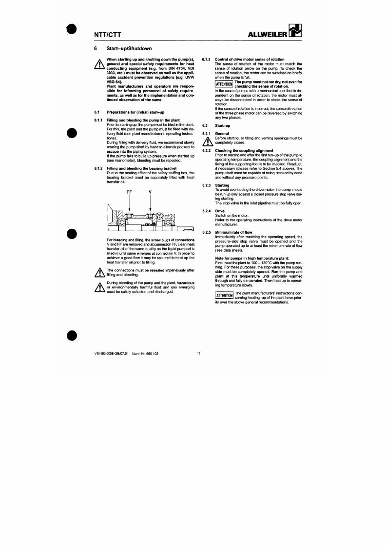
7/18/2019 M14 Thermal Fluid
http://slidepdf.com/reader/full/m14-thermal-fluid 88/486
6 Start-up/Shutdown
A
When starting up and shutting down the pump (s),
general and special safety requirements for heat
conducting equipment (e.g. from DIN 4754, VDI
3033,
etc.) must be observed as well as the app li
cable accident prevention regulations (e.g. U W /
VBG 64).
Plant manufacturers and operators are respon
sible for informing personnel of safety require
ments, as we ll as for the implementation a nd con
tinued observation of the same.
6.1 Preparations for (initial) star t-up
6.1.1 Filling an d bleeding the pump in the plant
Prior to starting u p, the p ump must l e bled In the plant.
For this, the plant and the pu mp must l3e fi lled with d e
livery fluid (see plant manufacturer's operating Instruc
tions).
During fi l l ing with delivery f lu id, we recommend slowly
rotating the pump shaft by han d to allow air pockets to
escape into the piping system.
If the pump fails to build up pressure when started up
(see manome ter) , bleeding must
be
repeated.
6.1.2 Filling and bleeding the bearing bracket
Due to the sealing effect of the safety stuff ing box , the
bearing bracket must be separately f i l led with heat
transfer oil.
6.1.3 Control of drive moto r sens e of rotation
The sense of rotation of the motor must match the
sense of rotation arrow on the pump. To check the
sense of rotation, the m otor can be switched on briefly
when the pump is
full.
The pump must not run dry, not even for
checking the sen se of rotation.
T T E N T I O N
In the case of pumps with a mechanical seal that is de
pendent on the sense of rotation, the motor must al
ways be disconnected in order to check the sense of
rotation.
if the se nse of rotation is Incon^ect, the sense of rotation
of the three phase motor can be reversed by sw itching
any two phases.
6.2 Start-up
6.2.1
A
.2.2
6.2.3
General
Before starting, all fi l ling an d venting openings must be
completely closed.
Checking the coupling al ignment
Prior to starting and after the f irst mn-u p of the pump to
operating temperature, the co upling alignment and the
fixing of the suppo rting foot Is to be c hecked. Readjust,
if necessary (please refer to Section 5.4 above). The
pump shaft must be capable of being cranked by hand
and without any pressure points.
Starting
NTT/CTT
ALLWEILER
7/18/2019 M14 Thermal Fluid
http://slidepdf.com/reader/full/m14-thermal-fluid 89/486
6.2.6
6.2.7
A
6.2.8
Setting the pump power output values
The pressure-side stop valve must be opened unti l the
required pump power output values are obtained (see
data sheet).
Unti l the operating temperature has been
reached,
it may be necessary to run the
6.4
Measures in the event of standsti lls
A T T E N T I O N
pump at a reduced capacity. This wil l compensate for
the increased power consumption due to high viscosity.
Temperature
In order to prevent injuries due to bums, at pumping
liquid temperatures higher than 60°C protective de
vices In accordance with EN 809 must be provided on
site.
A H E N T I O N
It must be ensured that the pum p ho using
is evenly heated. Differences in tempera
ture b etween the top and bottom of t h e pump, as well as
sudden temperature ch anges, should be avoide d.
Temperature changes in the material of more th an
SO'C per minute are not permissible.
Spare pump
A spare pump belonging to the plant must always be
kept ready for operation. For these purposes, the stop
valve on the supply side must be completely open. The
stop valve on the outlet side must be opened to such a
degre e that the pump, f i lled and Weeded, has operating
temperature.
Pumped liquid
May solidify
+
has a preservative effect
<3>
May solidify
+•
does not have a preserva
tive effect
Does not solidi^
+
has a preservative effect
Does not solidify
+
does not have a presen/a-
tive effect
Measures in ttie event of
brief standstill
Hear or drain pump
Hear or drain pump
-
-
Measures in the event of
prolonged standstill
Drain pump
Drain and preserve pump
-
Drain arxj preserve pump
® See section 3.3
A T T E N T I O N
In plants in which imperm issible tem pera
ture may arise due to failure of the o perat
NTT/CTT
ALLWEILER
7/18/2019 M14 Thermal Fluid
http://slidepdf.com/reader/full/m14-thermal-fluid 90/486
7 Maintenance/Repair
7.1 Maintenance
• The instructions in Section 2, Safety, must be
observed in maintenance and repair work.
• Regular mon itoring and maintena nce of the pump
and the drive motor are essential for optimum ser
vice l i fe an d sa fety.
7.1.1 General mon itoring
1. The pum p mus t not run dry.
2.
The pump must not run in cavitation.
3. The minimum delivery rate must always be main
tained (see S ection 6.2..).
4. The drive motor must not be over loaded.
5. The bearing temperature of roll ing bearings must
not exceed 120*C.
6. The shaft seal must have no inadmissible leakage.
7. The pum p unit must not experience or generate an y
undue vibrations (e.g. as a resu lt of incorrect align
ment). Intemational standard ISO 10816 must be re
ferred to for assessment.
The pump side medium-lubr icated rol l ing bear ing is
maintenance-free.
The drive-s ide roll ing bearing is lubricated with spec ial
grease and is f i l led with greas e at the factory.
•
Bearing bracket size 360 and 470:
Sealed roll ing bearing with guard discs, provided
with a l i fetime greas e fi l l ing at the factory.
• Bearing bracket size 530 and 65 0:
Open roll ing bearing with Nilos rings and grease
fi l led at the factory. These bearings must be regu-
lariy relubricated.
For the relubrication periods, please refer to the
fol
lowing l ist ing.
Speed
mirr ' '
1450
1750
Bearing bracket size
530
650
Lubrication period in operating hours
11.400
10.100
10.500
9.300
Notes:
1. At a maximum ambient temperature of 35*0 and
maximum admissible operat ing temperature, the
temperature at the drive-side roll ing bearing is ap-
NTT/CTT
ALLWEILER
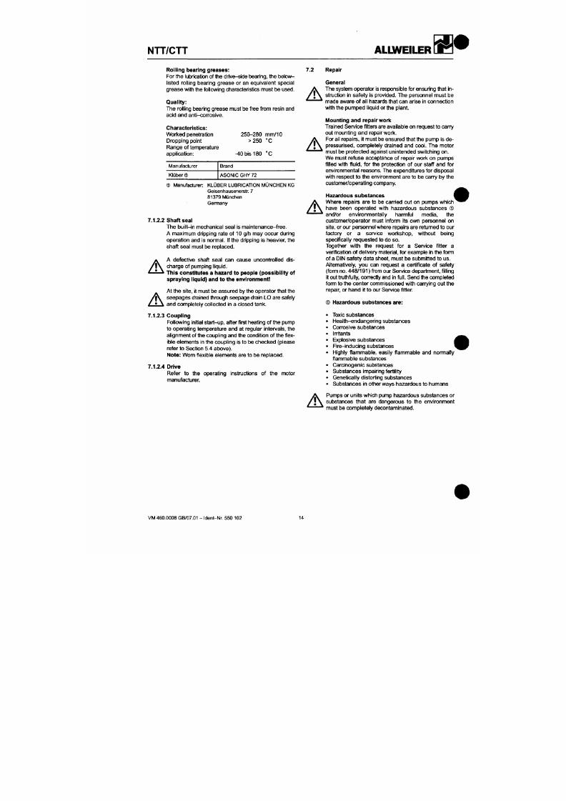
7/18/2019 M14 Thermal Fluid
http://slidepdf.com/reader/full/m14-thermal-fluid 91/486
Rolling bearing greases:
For the lubrication of the drive -side t)earing, the belov\f-
l isted roll ing bearing grease or an equivalent special
greas e w ith the following characteristics m ust be use d.
Quality:
The rolling bearing grease must be free from resin and
acid and anti-con-osive.
7.2 Repair
Characteristics:
Worked penetration
Dropping point
Range of temperature
application:
250-280 mm/10
> 2 5 0 ' C
-40 bis 180 'C
Manufacturer
Klüber ®
Brand
ASONIC GHY 72
(3) M anufacturer KLÜBER LUBRICATION MÜNCHEN KG
Gelsenhausenerstr. 7
81379 München
Germany
7.1.2.2
Shaft seal
The bui l t - in mechanical seal is ma intenance-free.
A maximum dripping rate of 10 g/h may occur during
operation and is nonnal. If the dripping is heavier, the
shaft seal must be replaced.
A
A defective shaft seal can cause uncontrolled dis
charge of pumping l iquid.
This constitutes a hazard to people (possibility of
A
A
A
General
The system operator is responsible for ensuring that in
struction in safety is provided. The personnel must be
made aw are of all hazards that can a rise in connection
with the pump ed l iquid or the p lant.
•Mounting and repair work
Trained Service f itters are available o n request to carry
out m ounting and repair wori<.
For all repairs, i t must be ensured that the pump is de-
pressurised, completely drained and cool. The motor
must be protected against unintended switching on.
We must refuse acceptance of repair wori< on pumps
filled with fluid, for the protection of our staff and for
environmental reasons. The expenditures for disposal
with respect to the environment are to be cany by the
customer/operating company.
Hazardous substances
Where repairs are to be earned out on pumps which"
have been operated wi th hazardous substances ®
and/or environmentally harmful media, the
customer/operator must inform its own personnel on
site, or our person nel where repairs are retumed to o ur
factory or a service wori<shop, without being
specif ically requ ested to do so.
Together wrtt i the request for a Service f itter a
verif ication of delivery material, for example in the form
of a DIN safety data sheet, must be submitted to us.
Altematively, you can request a certif icate of safety
(form no. 448 /191 ) from our Service department, f i l l ing
NTT/CTT
ALIWEILER
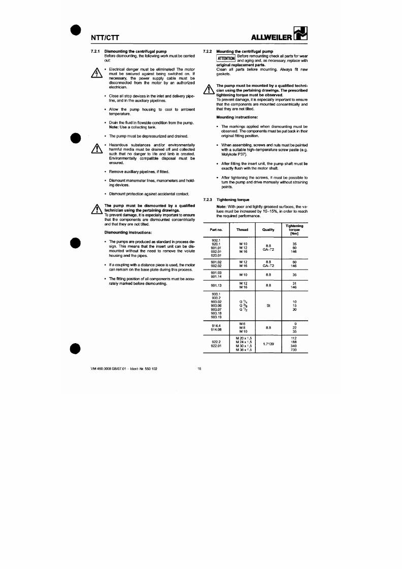
7/18/2019 M14 Thermal Fluid
http://slidepdf.com/reader/full/m14-thermal-fluid 92/486
7.2.1
A
A
Dismounting the centrifugal pump
Before dismo unting, the following work must be carried
out:
• Electrical dang er must be eliminated The motor
must be secured against being switched on. If
necessary, the power supply cable must be
disconnected from the motor by an authorized
electrician.
• Close all stop devices in the inlet and delivery pipe
line, and in the auxil iary pipelines.
• Allow the pump housing to cool to ambient
temperature.
• Drain the f luid in f lowable condit ion from the pump .
Note: Use a collecting tank.
• The pump must be depressur ized and drained.
• Hazardous substances and/or environmentally
harmful media must be drained off and collected
such that no danger to l i fe and l imb is created.
Environmentally compatible disposal must be
ensured.
• Remove auxil iary pipelines, if f i t ted.
• Dismount man ometer lines, manom eters and hold
ing devices.
• Dismount protection against accidental contact.
7.2.2 Moun ting the centrifugal pum p
Before remounting che ck all parts for wear
and aging and, as necessary, replace with
T T E N T I O N
A
original replacement parts.
Clean all parts before mounting. Always fit new
gaskets.
The pum p must be mounted by a quali fied techn i
cian using the pertaining drawings. The prescribed
tightening torque must be observe d.
To prevent dama ge, it is espe cially important to e nsure
that the componen ts are mounted concentrically and
that they are no t ti l ted.
•Mounting instructions:
• The mari<ings applied wh en dismoun ting mu st be
obse rved. The components mus t be put back in their
original fitting position.
• When assem bling, screws and nuts must be painted
with a sui table high-tem perature screw paste (e.g.
Molykote P37).
• After f i t t ing the insert unit, the pum p shaft mu st l ie
exactly f lush with the mo tor s haft.
• After t ightening the scre ws , it must
be
possible to
turn the pump and drive manually without straining
points.
NTT/CTT
ALLWEILER
æ»
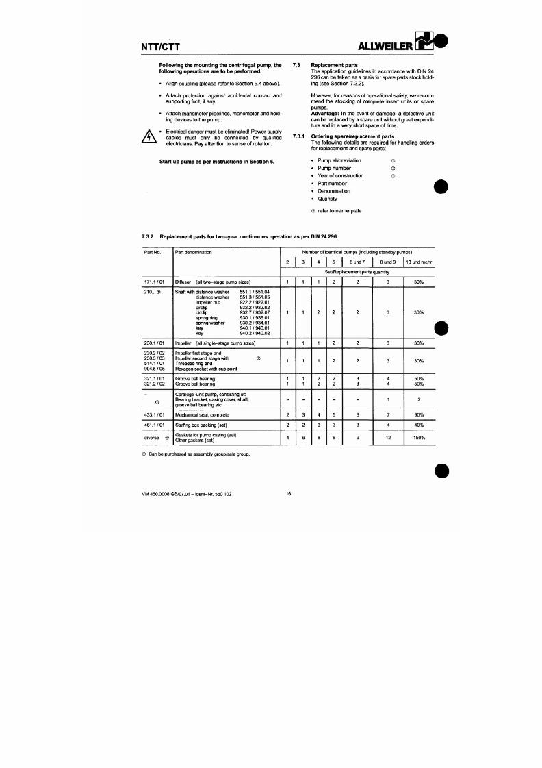
7/18/2019 M14 Thermal Fluid
http://slidepdf.com/reader/full/m14-thermal-fluid 93/486
A
Following the mounting the centri fugal pum p, the
fol lowing operations are to be p erforme d.
• Align coupling (please refer to Section 5.4 above).
• Attac h protection against accidental contac t and
supporting foot, i f any.
• Attach manome ter pipelines, mano meter and hold
ing devices to the pump.
Electrical danger mus t be eliminatedl Pow er supply
cables must only be connected by qualif ied
electricians. Pay attention to sense o f rotation.
7.3 Replacement parts
The application guidelines in accordance with DIN 24
296 can b e tak en as a basis for spare parts stock hold
ing (see Section 7.3.2).
However, for reasons of operational safety, we rec om
mend the stocking of complete insert units or spare
pumps.
Advantage: In the event of damage, a defective unit
can be replaced by a spare unit without great expen di
ture and in a very short space o f t ime.
7.3.1 Ordering spare/replacement parts
The following details are required for handling orders
for replacement and spare parts:
Start up pump as per instructions in Section 6.
P u m p a b b r e v i a t i o n
P u m p n u m b e r
Y e a r o f c o n s t r u c t i o n
P a r t n u m b e r
D e n o m i n a t i o n
Quant i t y
ffi
®
®
® refer to nam e plate
7.3.2 Replacement parts for two -yea r continuous operation as per DIN 24 296
Part No.
Part denomination Number of ident ical pumps (including standby pumps)
2 3 4 5 6 und 7 8 und 9 10 und mehr
NTT/CTT
ALLWEILER
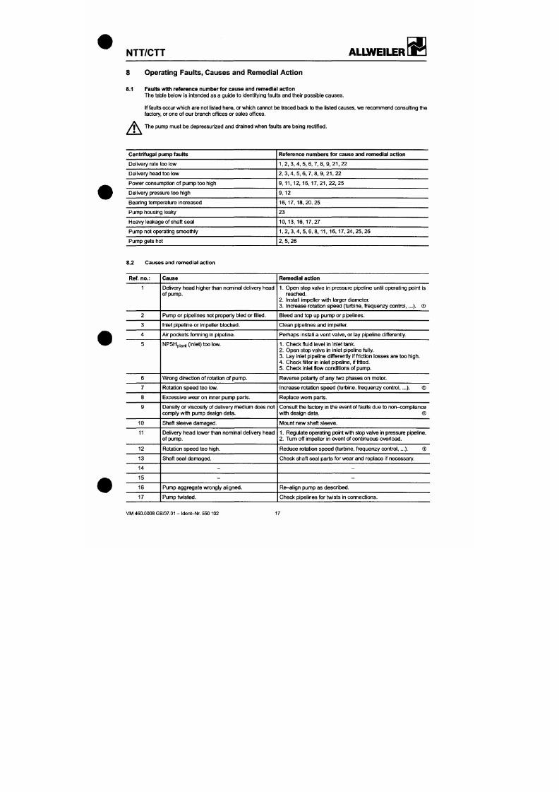
7/18/2019 M14 Thermal Fluid
http://slidepdf.com/reader/full/m14-thermal-fluid 94/486
8 Operating Faults, Causes and Remedial Action
8.1 Faults with referen ce number for caus e and remed ial action
The table below is intended as a guide to identifying faults and their possible ca uses .
If faults occur which a re not l isted here, or which cannot be traced back to the l isted causes, we recomm end consult ing the
factory, or one of ou r branch off ices or sales off ices.
The pump must be depressurized and drained when faults are being rectif ied.
A
Centrifugal pump faults
Delivery rate too low
Delivery head too low
Power consumption of pump too high
Delivery pressure too h igh
Bearing temperature increased
Pump housing leaky
Heavy leakage of shaft seal
Pump not operating smoothly
Pump gets hot
Reference numb ers for cause and remedial action
1,2,3,4,5,6,7,8,9,21,22
2 , 3 , 4 , 5 , 6 , 7 , 8 , 9 , 2 1 , 2 2
9 , 1 1 , 1 2 , 1 6 , 1 7 , 2 1 , 2 2 , 2 5
9 ,12
1 6 , 1 7 , 1 8 , 2 0 , 2 5
23
1 0 , 1 3 , 1 6 , 1 7 , 2 7
1,2, 3, 4 , 5, 6, 8, 11 , 16 , 17 , 24, 25, 26
2, 5, 26
8.2 Causes and remedial action
NTT/CTT
ALLWEILER
» •
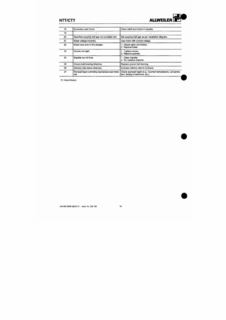
7/18/2019 M14 Thermal Fluid
http://slidepdf.com/reader/full/m14-thermal-fluid 95/486
18
19
20
21
22
23
24
25
26
27
Excessive axial thrust.
-
Specified coupling half gap not com plied
with.
l\4otor voltage incon-ect.
Motor runs only to two phases.
Screws not tight.
Impeller out-of-true.
Groove ball bearing defective.
Delivery rate below minimum.
Pumped liquid corroding m echanical seal mate
rial.
Clean relief bore holes in impeller.
-
Set coupling half gap as per Installation diagram.
Use motor with correct voltage.
1.
Check cable connection.
2.
Replace fuses.
1.
Tighten screws.
2.
Replace gaskets.
1.
Clean impeller.
2.
Re-balance impeller.
Replace groove ball bearing.
Increase delivery rate to minimum.
Check pumped liquid
(e.g.:
incon-ect temperature , concentra
tion,
dosing of additives, etc.)
® Consult factory
NTT/CTT
ALLWEILER
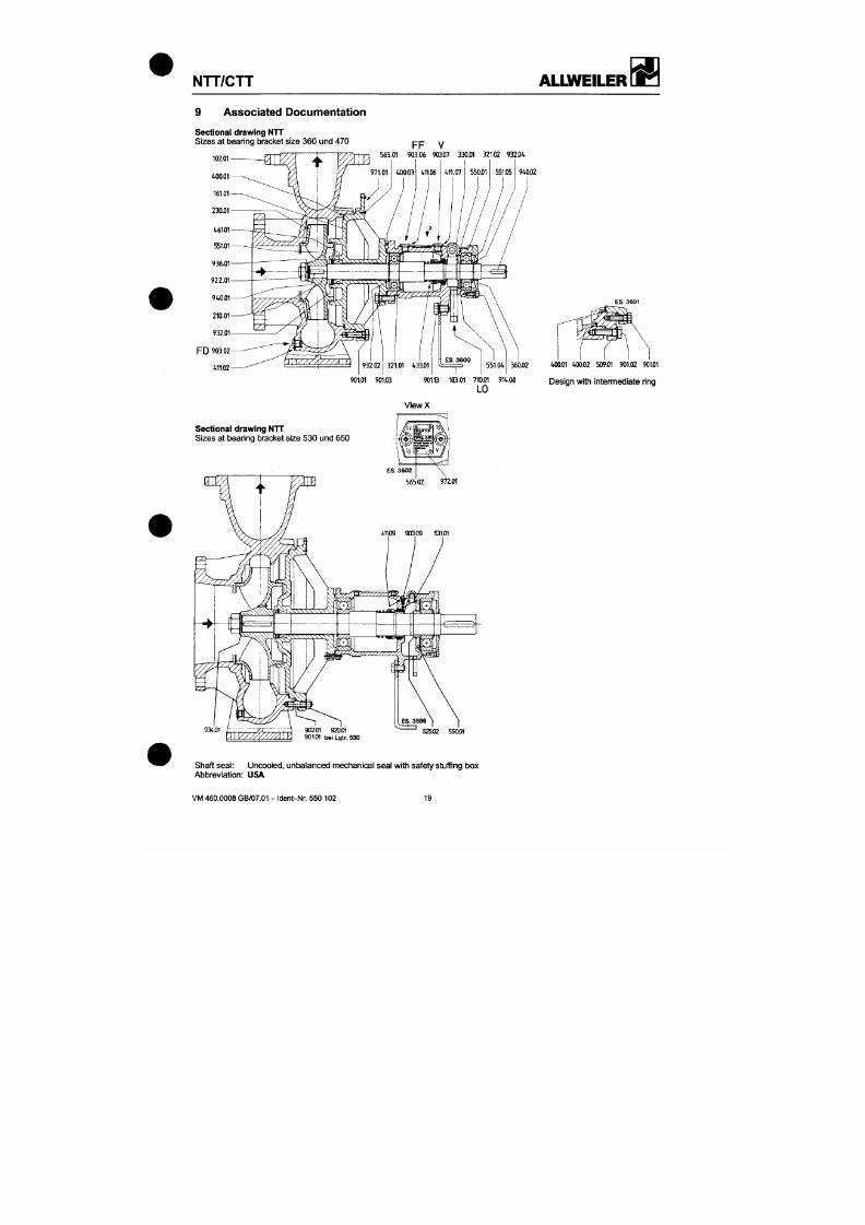
7/18/2019 M14 Thermal Fluid
http://slidepdf.com/reader/full/m14-thermal-fluid 96/486
Associated Documentation
Sectional drawing NTT
Sizes at bearing bracket size 360 und 470
FF V
565.01 903.06 903.07 330.01 321.02 932f lt
9W.02
360.02
901.01 901.03
901.B 183fl1 710.01 914.08
LO
«».01 «•00.02 509.01 901.02
901J01
Des ig n w i th in te rme d ia te r ing
ViewX
NTT/CTT
ALlMfEILER
æ »
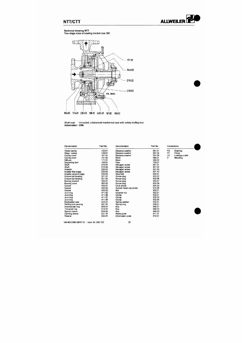
7/18/2019 M14 Thermal Fluid
http://slidepdf.com/reader/full/m14-thermal-fluid 97/486
Sectional drawing NTT
Two-stage sizes at bear ing bracket size 360
171.01
940.03
210.02
230.02
904 05 514.01 230.03 108.01 400 .01 161.02 901.01
NTT/CTT
ALLWEILER
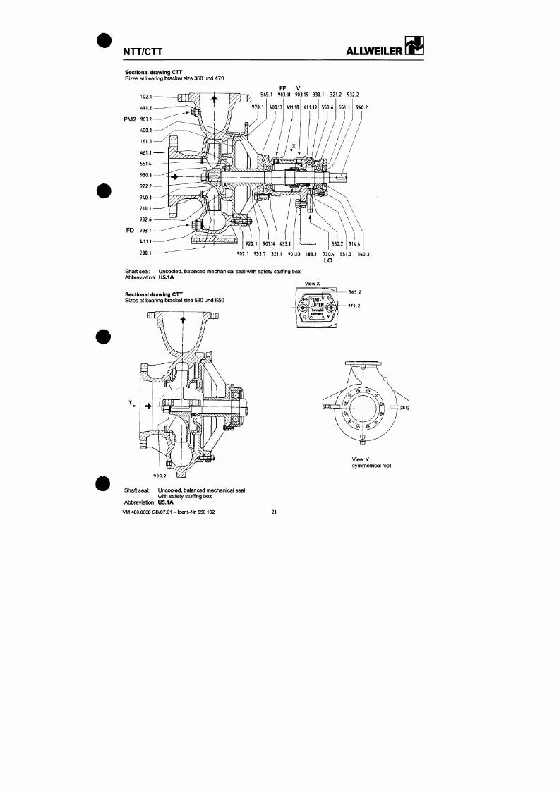
7/18/2019 M14 Thermal Fluid
http://slidepdf.com/reader/full/m14-thermal-fluid 98/486
Sectional drawing CT T
Sizes at bear ing bracket size 360 und 47 0
FF V
565 .1 903.18 903.19 330 .1 3 21.2 932 .2
551.1 I 9W).2
902.1 932.7 321.1 901.13 183.1 730.1» 551.3 360.2
LO
NTT/CTT
ALIWEILER
W ß
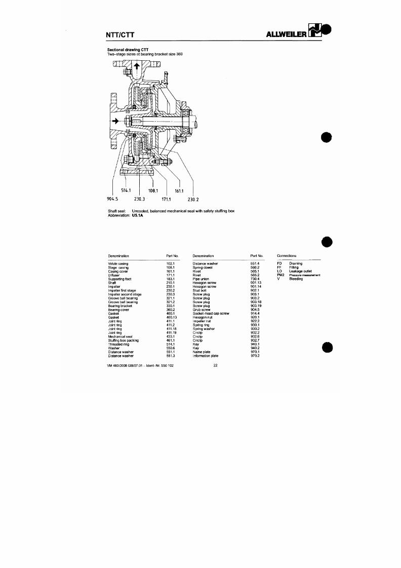
7/18/2019 M14 Thermal Fluid
http://slidepdf.com/reader/full/m14-thermal-fluid 99/486
Sectional drawing CTT
Two-stage sizes at bearing bracket size 360
NTT/CTT
ALIWEILER
7/18/2019 M14 Thermal Fluid
http://slidepdf.com/reader/full/m14-thermal-fluid 100/486
Order-specific Documentation
These operating instructions are supplemented by the following documents:
Acceptance of order No .
Data sheet No .
Installation drawing No .
Sectional drawing No .
Part list No.
NTT/CTT
ALLWEILER
^
7/18/2019 M14 Thermal Fluid
http://slidepdf.com/reader/full/m14-thermal-fluid 101/486
ALLWEILER
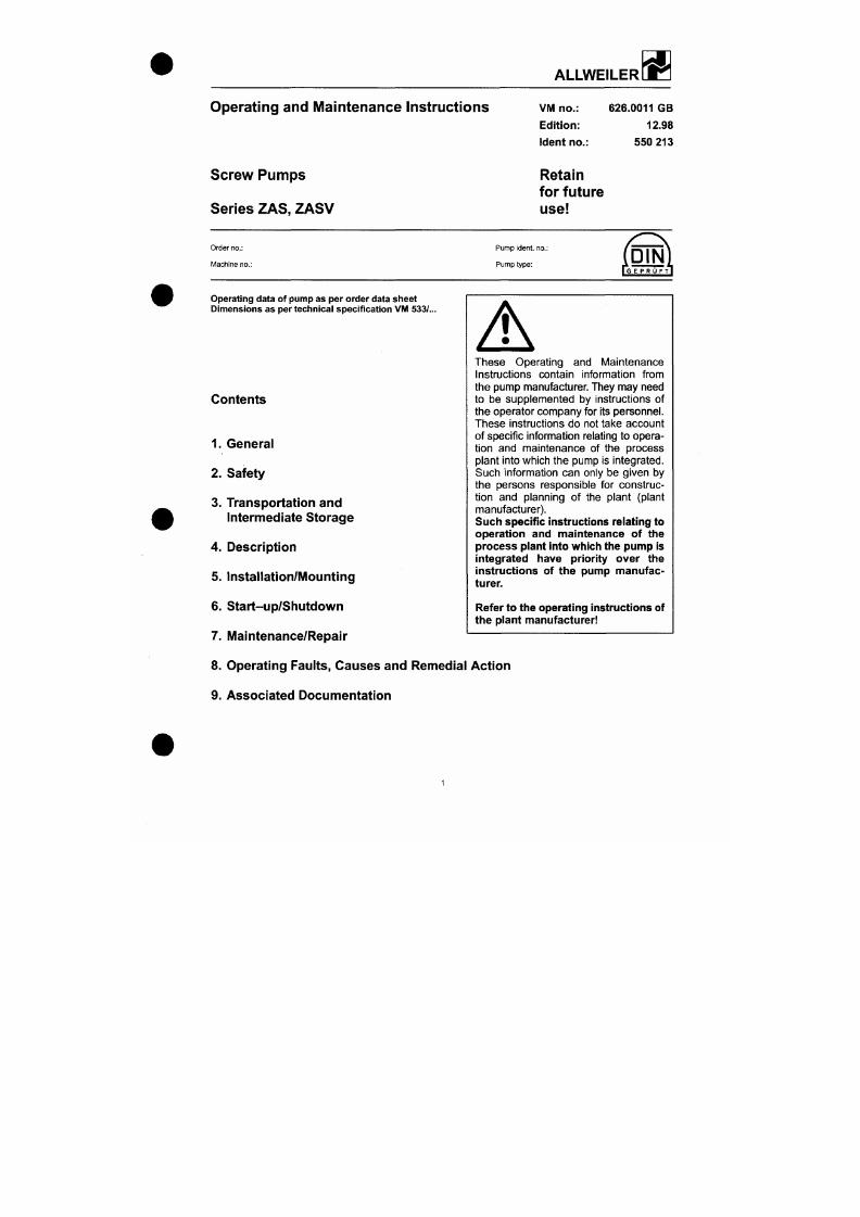
7/18/2019 M14 Thermal Fluid
http://slidepdf.com/reader/full/m14-thermal-fluid 102/486
Operating and Maintenance Instructions
Screw Pumps
Series Z AS, ZASV
VM no.:
Edition:
Ident no.:
Retain
for future
use
626.0011 GB
12.98
55 0 213
Order no.:
Machine no.:
Pump ident. no.:
Pump type:
Operating data of pump as per order data sheet
Dimensions as per technical specification VIM 533/..
Contents
A
hese Operating and Maintenance
Instructions contain information from
tiie pump manufacturer. Ttiey may need
to be supplemented by instructions of
the ope rator company for its personnel.
ZAS, ZASV
ALLWEILER
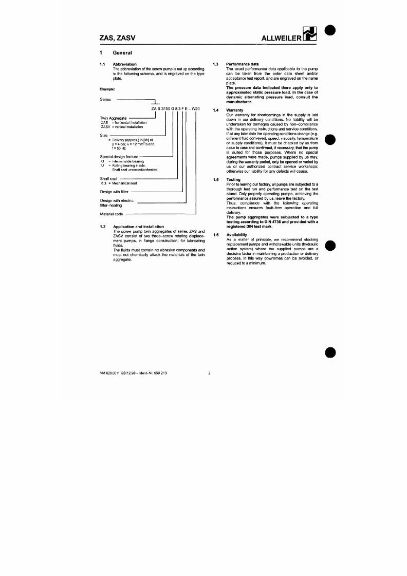
7/18/2019 M14 Thermal Fluid
http://slidepdf.com/reader/full/m14-thermal-fluid 103/486
General
1.1 Abbreviation
The abbreviation of the screw pump is set up according
to the following schema, and is engraved on the type
plate.
Example:
Series
Z A S 3 15 0 G 8 .3 F E - W 2 0
Twin Aggregate
ZAS = horizontal installation
ZASV = vertical Installation
Size
= Delivery (approx.) in [l/h] at
p = 4
bar,
v = 12 mm /s and
f = 50Hz
Special design feature
G = Internal slide bearing
U = Rolling bearing inside.
Shaft seal uncooled/unheated
Shaft seal
8.3 = Mechanical seal
Design with filter
1.3 Pe rformanc e data
The exact performance data applicable to the pump
can be taken from the order data sheet and/or
acceptanc e test report, and are engraved on the name
plate.
The pressure data indicated there apply only to
approximated static pressure load. In the case of
dynamic alternating pressure load, consult the
manufacturer.
1.4 Warranty
Our wananty for shortcomings in the supply is laid
down in our delivery condit ions. No l iabil i ty wil l be
undertaken for damages caused by non-compl iance
with the operating instructions and service condit ions.
If at any later date the ope rating co nditions change (e.g.
different f luid convey ed, speed , viscosity, temperature
or supply condit ions), i t must be checked by us from
case to case and confinned, if necessary, that the pump
is suited for those purposes. Where no special
agreements were made, pumps suppl ied by us may,
during the warranty period, only be opened or varied by
us or our authorized contract service workshops;
othenA/ise our liability for any defects will cease.
1.5 Testing
Prior to leaving our factory, all pumps are subjected to a
thorough test run and performance test on the test
stand. Only properly operating pumps, achieving the
ZAS, ZASV
ALLWEILER
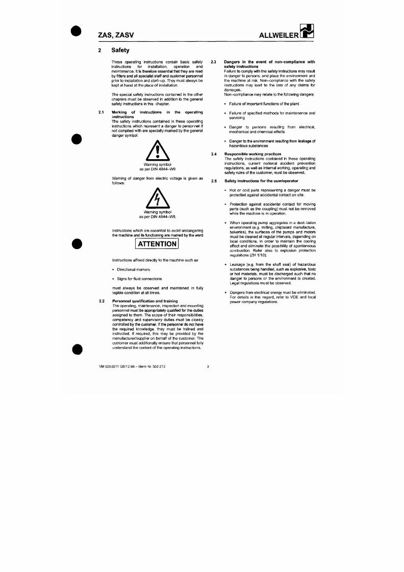
7/18/2019 M14 Thermal Fluid
http://slidepdf.com/reader/full/m14-thermal-fluid 104/486
2 Safety
2.1
These operating instructions contain basic safety 2.3
instructions for installation, operation and
maintenance. It Is therefore essential that they are read
by fitters and a ll specialist staff and c ustomer person nel
prior to installation and start-u p. They must always be
kept at hand at the place of installation.
The special safety instructions contained in the other
chapters must be observed in addit ion to the general
safety instructions in this chap ter.
Marking of instructions in the operating
instructions
The safety instructions contained in these operating
instructions which represent a danger to personnel if
not complied with are specially marked by the g eneral
danger symbol:
A
Warning symbol
as per DIN 4844-W9
arning of danger from electric voltage is given as
follows:
2.4
Dangers in the event of non-compliance with
safety instructions
Failure to comply with the safety instructions may result
in danger to persons, and place the environment and
the machine at r isk. Non-compliance with the safety
instructions may lead to the loss of any claims for
damages.
Non-compliance may relate to the following dangers:
• Failure of important functions of the plant
• Failure of specif ied methods for maintena nce and
servicing
• Danger to persons result ing from electrical,
mechanical and chemical effects
• Da nge r to the environm ent resulting from leakage of
hazardous substances
Respon sible working practices
The safety instructions contained in these operating
instructions, current national accident prevention
regulation s, as well as intemal working, operating and
safety rules of the customer, must be observed.
2.5 Safe ty instructions for the user/operator
• Hot or cold parts representing a dange r must be
Z A S , ZASV
ALLWEILER
7/18/2019 M14 Thermal Fluid
http://slidepdf.com/reader/full/m14-thermal-fluid 105/486
2.6 Safety instructions for maintena nce, inspection
and mounting work
The operator company shall ensure that all
maintenance, inspection and mounting work is
performed by authorized and qualif ied specialist
personnel who have thoroughly studied the operating
Instructions.
Work on the machine is only to be earned out when the
machine is at a standsti l l . The means of shutdown of
the machine described in the operating instructions
must always be followed.
Pumps or aggregates handling f luids which are
detrimental to health must be decontaminated. All
safety and protective devices must immediately be
refitted and made operational on completion of the
work.
The instnjctions under Section 6 .1, "Preparation for
start-up", must be observed before restarting.
2.7 Unauthorized conversion and production of
replacement parts
Conversion or modification of the machines is only
permissible after consultation with the manufacturer.
Original replacement parts and accessories approved
by the manufacturer serve safety purposes. If other
parts are used the manu facturer cannot be held l iable
for the consequences.
2.8 Impen nissible modes of operation
The operating safety of the machine supplied is only
ensured when it is used in accordance w ith Section 1 of
3.1
3.2
A
Transportation and Intermediate
Storage
Packaging
Attention must be paid to the markings on the
packaging.
The suction and pressure sides and all auxil iary
connections must always be closed during
transportation and storage. The closing plugs must be
removed when the pump aggregate is installed.
Transportation
The pump or pump aggregate is to be safely
transported to the place of installation, if required by
means of lifting gear.
The generally applicable safety regulations for
lifting loads must be observed. The crane device
and cables must be adequately dimensioned. The
cables must not be attached to the attachment eyes
of the motor.
A H E N T I O N
During transportation ensure that the
aggregate is secured against toppling
over. The attachment eyes of the m otor can be used to
secu re it.
Transport damage
Check the pump for damage on receipt.
Any da mage detected must be notified im-
H E N T I O N
mediately.
Z A S , ZASV
ALLWEILER
3.3 Preservation and storage of the screw pumps 3.3.1.4 Depreservation
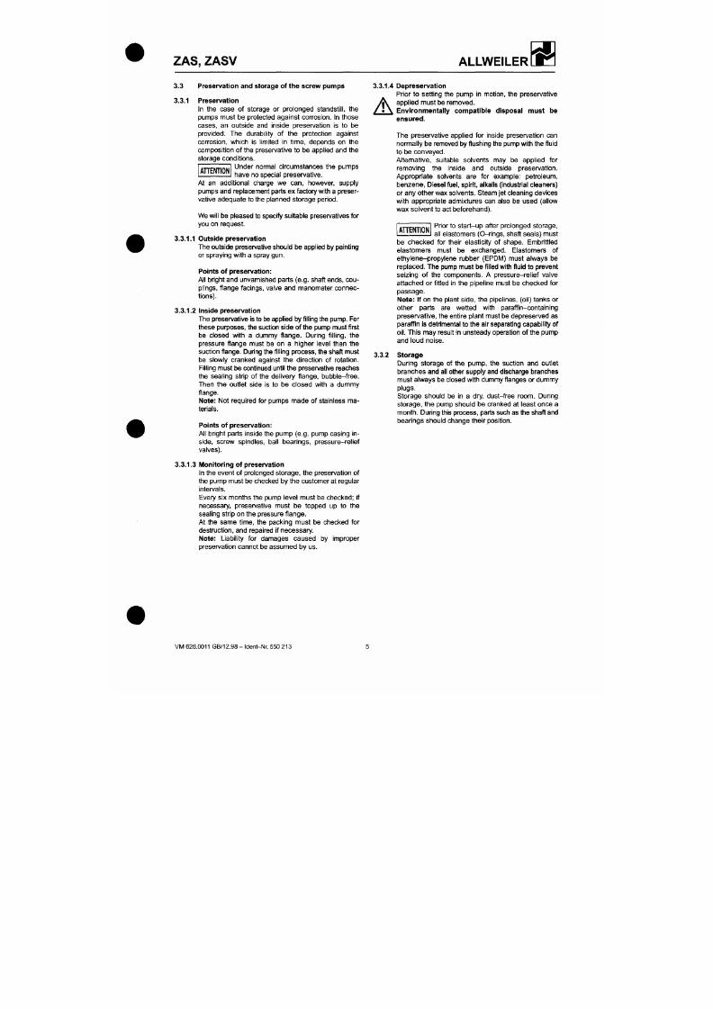
7/18/2019 M14 Thermal Fluid
http://slidepdf.com/reader/full/m14-thermal-fluid 106/486
A H E N T I O N
3.3.1 Preservation
In the case of storage or prolonged standsti l l , the
pumps must be protected against corrosion. In those
cases, an outside and inside preservation is to be
provided. The durabil i ty of the protection against
corrosion,
which is l imited In t ime, depends on the
composit ion of the preservative to be applied and the
storage condit ions.
Under normal circumstances the pumps
have no special preservative.
At an addit ional charge we can, however, supply
pumps a nd replacement parts ex factory with a preser
vative adequate to the planned storage period.
We will be pleased to specify suitable preservatives for
you on request.
3.3.1.1 Outside preservation
The outside preservative should be applied by painting
or spraying with a spray gun .
Points o f preservation:
All bright and unva mished p arts (e.g. shaft ends,
cou
plings, f lange facings, valve and manometer connec
tions).
3.3.1.2 Inside preservation
The presen/a tive Is to be applied by filling the pump. For
these pu rposes, the suction side of the pump must f irst
be closed with a dummy flange. During fi l l ing, the
pressure f lange must be on a higher level than the
Prior to sett ing the pump in motion, the preservative
^ \ appl ied must be removed.
Environmental ly
ensured.
compatible disposal must be
The preservative applied for inside preservation can
norm ally be removed by flushing the pump with the fluid
to be conveyed.
Alternative, suitable solvents may be applied for
removing the inside and outside preservation.
Appropriate solvents are for example: petroleum,
benzen e, Diesel fuel, spirit, alkalis (industrial cleaners)
or any othe r wax solvents. Steam jet cleaning devices
with appropriate admixtures can also be used (allow
wax solvent to act beforehand).
A H E N T I O N
Prior to start-up after prolonged storage,
all elastomers (0-rings, shaft seals) must
be checked for their elasticity of shape. Embritt led
elastomers must be exchanged. Elastomers of
ethylene-propylene aibber (EPDM) must always be
rep laced.
The pump mus t be fi l led with f iuid to prevent
seizing of the components. A pressure-relief valve
attached or f i t ted in the pipeline must be checked for
passage.
Note: If on the plant side, the pipelines, (oil) tanks or
other parts are wetted with paraff in-containing
preservative, the entire plant must be depreserved as
paraffin is detrimental to the air separating capability of
o i l .
This m ay result in unsteady operation of the pump
and loud noise.
ZAS, ZASV
ALLWEILER
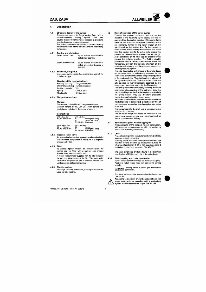
7/18/2019 M14 Thermal Fluid
http://slidepdf.com/reader/full/m14-thermal-fluid 107/486
Description
4.1 Structural design of the pumps
Three-screw pumps in f lange design form, wi th a
double- threaded dr iving spindle and two
double-threaded idler spindles, enclosed in a housing
insert with narrow running clearance.
The delivery elements are installed in a pump housing
whic h is closed off on the drive side and the end side by
pump caps.
4.1.1 Bearing and lubrication
Sizes 150 to 3150: By an intemal me dium -lubri
cated slide bearing.
4.1.2
Sizes 3600 to 6450:
By an intemal medium-lubr i
cated groove ball bearing to
DIN 625.
Shaft seal, design 8.3
Uncooled, maintenance-free mechanical seal of the
unbalanced type.
Materials of the mec hanical
seal:
Rotating seal ring: Tung sten carbide
Stationary seal
ring:
Tungsten carbide
Auxil iary gaskets: Viton
Spring:
CrNIM o steel
M etal parts : CrNilVIo steel
4.1.3 Flanges/connections
4.2 Mode of operation of the screw pumps
Through the suction connection and the suction
chamber in the reversing valve casing, the f luid is
conveyed into the suction chamber of the pump. From
there the fluid f lows into the spindle cham bers, wh ich
are constantly formed by the rotary motion at the
spindle end on the suction side. By the translatory
rotary motion, the cham bers f i l led with the f luid mov e
from the suction side to the outlet side. During this
process the closed chamber volum e does not change .
At the spindle end on the outlet side the cham ber opens
towards the delivery chamber. The fluid is steadily
pushed out into the delivery cham ber from whe re it is
transported, through the delivery chamber of the
reversing valve casing and the pressure connection,
into the pressure pipeline.
The axial thrust acting o n the face s of the profile flanks
on the ouflet side is hydraulically balanced by an
appropriate dimensioning of the compensating piston
of the driving spind le. Thus the bea ring is relieved of
the hydraulic axial thrust. The axial thrust of the two
idler spindles is hydrodynamically absorbed by the
pump cover, non -drive side or by the fi lter casing.
The idler spindles a re hydraulically driven by means of
appropriate dimensioning of the spindles. Only the
torque resulting from the fluid friction is transmitted via
the profile flanks. They are therefore practically
stress-ft-ee, and not subject to any wear.
As a result of the cons tant chamber volume the medium
ZAS, ZASV
ALLWEILER
If no contact protection is provided, it must be attached
Switching diagram
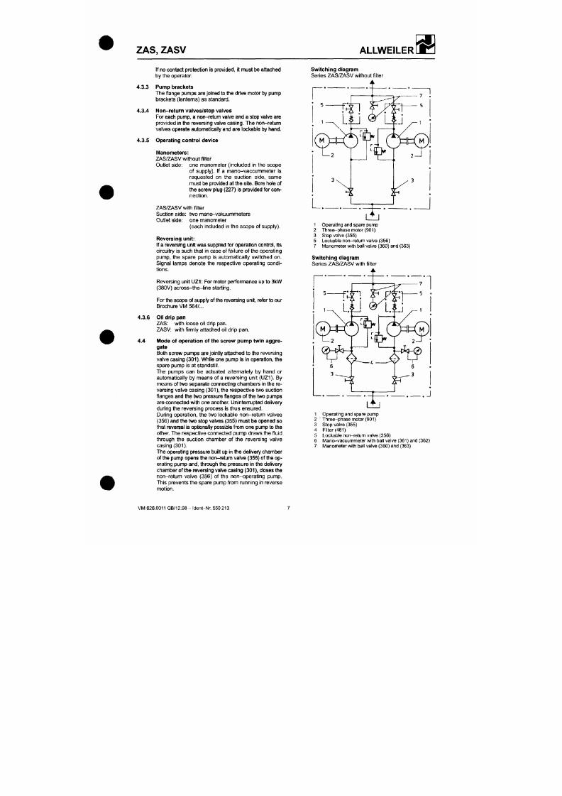
7/18/2019 M14 Thermal Fluid
http://slidepdf.com/reader/full/m14-thermal-fluid 108/486
by the operator
4.3.3 Pump brackets
The flange pumps are joined to the drive motor by pump
brackets (lanterns) as standard.
4.3.4 Non-return valves/stop valves
Fo r each pump, a non -return valve and a stop valve are
provided in the reversing valve casing . The non-return
valves operate automatically and are lockable by hand.
4.3.5 Operating control device
Manometers:
ZAS/ZASV without filter
Outlet side: one manometer (Included In the scope
of supply). I f a mano-vaccummeter is
requested on the suction side, same
mu st be provided at the site . Bore hole of
the screw plug (227) is provided for con
nection.
ZAS/ZASV with filter
Suction side: two mano-vakuummeters
Outlet side: one manom eter
(each included In the scop e of supply).
Reversing unit:
If a reversing unit wa s supplied for operation control, its
circuitry is such tha t in case of failure of the operating
pump, the spare pump is automatically switched on.
Signal lamps denote the respective operating condi
tions.
Series ZAS/ZASV without filter
1 Operating and spare pump
2 Three-pha se motor (901)
3 Stop valve (355)
5 Lockable non-retum valve (356)
7 Manometer with ball valve (360) and (363)
Switching diagram
Series ZAS/ZASV with filter
Z A S ,
ZASV
ALLWEILER
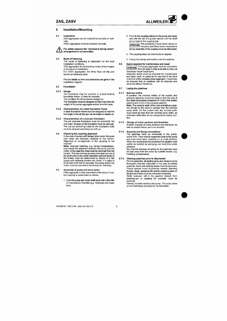
7/18/2019 M14 Thermal Fluid
http://slidepdf.com/reader/full/m14-thermal-fluid 109/486
Installation/Mounting
5.1 Installation
ZAS aggregates can be installed horizontally or verti
cally.
ZASV aggregates must be Installed vertically.
A
For safety reasons the "downward-facing motor"
arrangement is not permitted.
5 .2
Mode of fastening
The mode of fastening Is dependent on the local
Installation conditions.
2 J ^ S aggregates are fastened by means of foot angles
at the place of installation.
For ZASV aggregates, the firmly fixed oil drip pan
serves as fastening base.
Precise details on form and dimensions are given in the
Installation diagram.
5.3 Foundation
5.3.1 Design
The foundation may be concrete or a load-bearing
foundation frame, of steel for example.
The condition for all foundation designs is:
The foundation must be designed so that it can take the
weight of the pump aggregate across Its entire area.
5.3.2 Characteristics of a steel foundation frame
5.6
Push on the coupling halves on the pump and m otor
side with the aid of a pusher device until the shaft
end is flush to the coupling hu b.
The possibility of axia l shock stress on
the pump and drive motor components
T T E N T I O N
during assembly of the coupling must be eliminated.
3. The coupling does not need to be re-allgned.
4 . Flange the pumps and motors onto the lantem s.
Space required for maintenance and repair
A H E N T I O N
The pump aggregate must be accessible
from all sides In order to be able to carry out
necessary visual inspections.
Adequate space must be provided for maintenance
and repair work, in particular for removal of the drive
motors or of the complete pump aggregate. It must also
be ensured that all pipelines can be attached and
removed without hindrance.
5.7 Laying the pipelines
5 .7.1 Nominal widths
If possible, the nominal widths of the suction and
pressure pipelines should be rated so that the rate of
flow does not exceed a maximum of 1 m/s In the suction
pipeline and 3 m/s In the pressure pipeline.
Note: The nom inal width of the inlet and delivery pip e
line should be the same or greater than the nominal
ZAS, ZASV
ALLWEILER
5.7.5 Non-r eturn valves/stop valves
5.9
Electrical connections
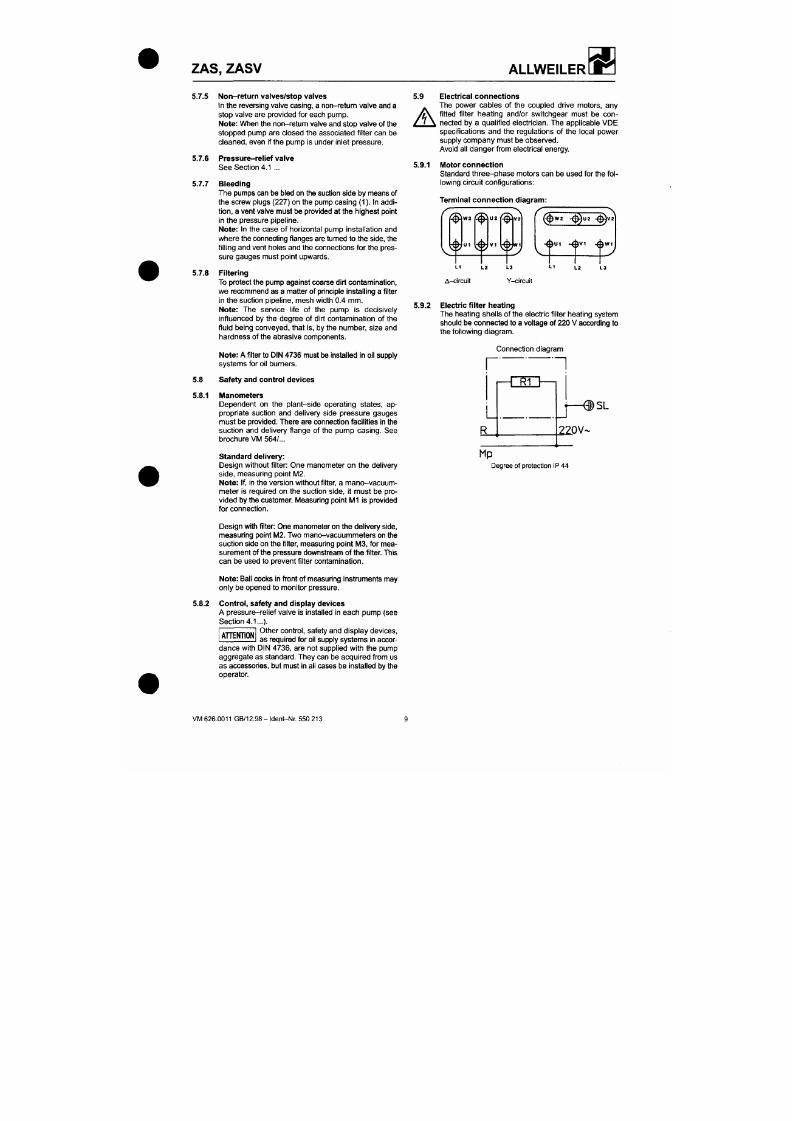
7/18/2019 M14 Thermal Fluid
http://slidepdf.com/reader/full/m14-thermal-fluid 110/486
In the reversing valve casing, a no n-return v alve and a
stop valve are provided for each pump.
Note:
When the n on-return valve and stop valve o f the
stopped pump are closed the associated fi l ter can be
cleaned, even If the pu mp Is under Inlet pressure.
5.7.6 Pres sure-rel ief valve
See Section 4.1 ...
5.7.7 Bleeding
Th e pum ps can be bled on the suction side by means of
the screw plugs (227) on the pump cas ing (1). In addi
t ion,
a vent valve must be provided at the highest point
in the pressure pipeline.
Note: In the case of horizontal pump installation and
where the connecting flanges are turned to the side, the
fi l ling and vent holes and the connections for the pres
sure gauges must point upwards.
5.7.8 Filtering
To protect the pum p against coarse dirt contamination,
we recommend as a matter of principle installing a filter
in the suction pipeline, mes h width 0.4 mm .
Note: The service l i fe of the pump is decisively
influenced by the degree of dirt contamination of the
fluid being conv eyed , that is, by the numb er, size and
hardness of the abrasive components.
Note: A filter to DIN 473 6 m ust be Installed in oil supply
systems for oil bumers.
5.8 Safety and control devices
A
The power cables of the coupled drive motors, any
fitted f i l ter heating and/or switchgear must be con
nected by a qualif ied electrician. The applicable VDE
specif ications and the regulations of the local power
supply com pany must be observed.
Avoid all dange r from electrical ene rgy
5.9.1 Motor connection
Standard three-phase motors can be used for the
fol
lowing circuit con figurations:
Terminal connection diagram:
^ v » 2 ( ^ " * ( ^ ' " ^ w i - ^ U 2 . ^ v a
^b
^b
v i ( ^ ^
-0U1 -A v i .Aw i
LI LZ
A-circult
L3
Y-clrcult
5 .9.2 Electric filter heating
The hea ting shells of the electric f il ter heating system
should be con nected to a voltage of 220 V according to
the fol lowing diagram.
Connection diagram
r'
"~]
Z A S , ZASV
ALLWEILER
Sta rt -u p/s h utdo wn
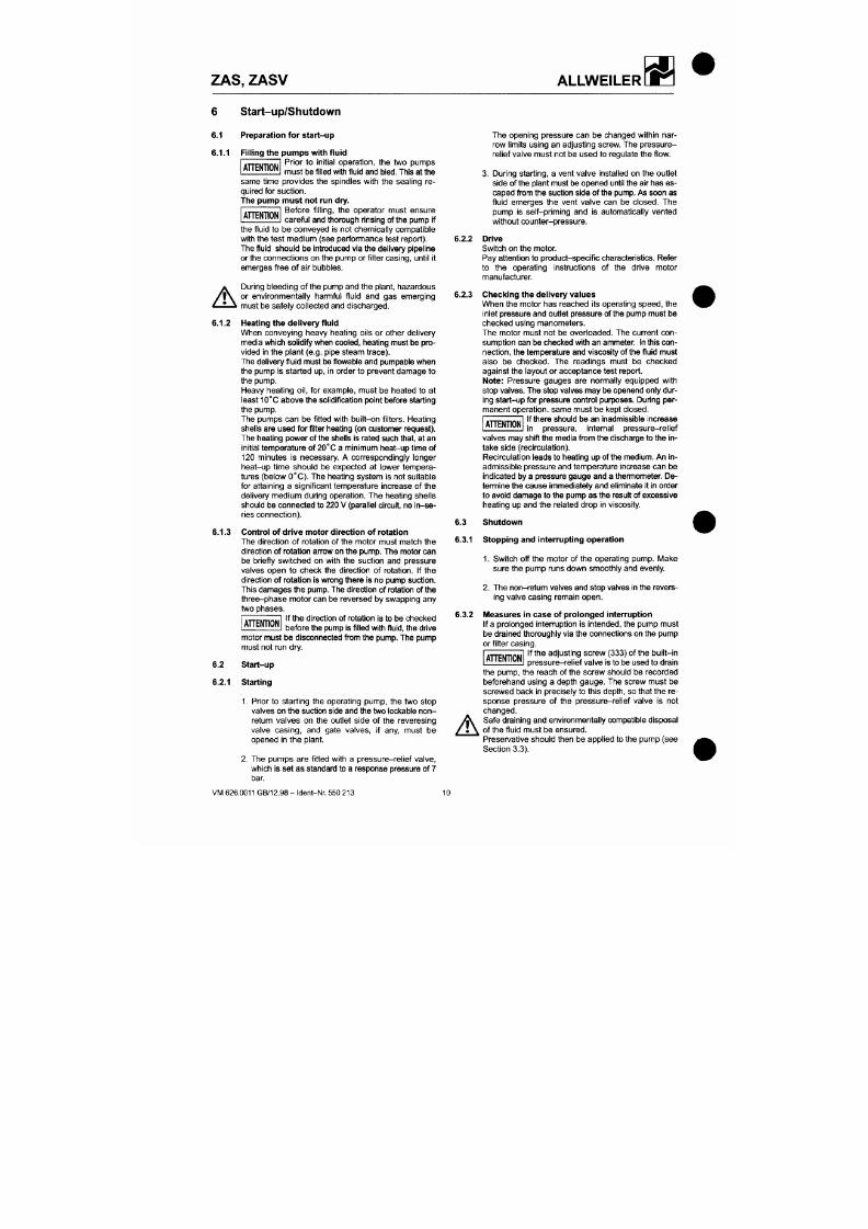
7/18/2019 M14 Thermal Fluid
http://slidepdf.com/reader/full/m14-thermal-fluid 111/486
6.1 Preparation for start-up
6.1.1
Filling the pu mp s with fluid
Prior to init ial operation, the two pumps
mu st be filled with fluid and bled. This at the
H E N T I O N
same time provides the spindles with the sealing re
quired for suc tion.
The pump must not run dry.
Before f i l l ing, the operator must ensure
careful and thorough rinsing of the pump if
H E N T I O N
A
the f luid to be conveyed is not chemically compatible
with the test med ium (see performanc e test report).
The fluid sho uld be Introduced via the delivery pipeline
or the con nections on the pump or f il ter casing, unti l i t
emerges free of air bu bbles.
During bleeding of the pump and the plant, hazardous
or environmentally harmful f luid and gas emerging
must be safely collected and discharged.
6.1.2 Heating the delivery fluid
When conveying heavy heating oils or other delivery
media which solidify when cooled, heating must be pro
vided in the plant (e .g. pipe steam trace).
The delivery fluid must be flowable and pum pable when
the pump is started up, in order to prevent damage to
the pump.
Heavy heating oil, for example, must be heated to at
least 10°C above the solidification point before starting
the pump.
6.2.2
6.2.3
The opening pressure can be changed within nar
row l imits using an adjusting screw. The pressure-
relief valve mu st not be used to regulate the flow.
3. During starting, a vent va lve Installed on the outlet
side o f the plant must be opene d until the air has es
caped from the suction side of the pump. As soon as
fluid emerges the vent valve can be closed. The
pump is self-priming and is automatically vented
without counter-pressure.
Drive
Switch on the motor.
Pay attention to product-specific characteristics. Refer
to the operating Instructions of the drive motor
manufacturer
Checking the del ivery values
When the motor has reached its operating speed, the
Inlet pressure and ouflet pressure of the pump must be
checked using manometers.
The motor must not be overioaded. The current con
sum ption can be checke d with an ammeter. In this
con
nection, the temperature and viscosity of the fluid must
also be checked. The readings must be checked
against the layout or accep tance test report.
Note: Pressure gauges are normally equipped with
stop valves. The stop valves may be openend only dur
ing start-up for pressure control purposes. During per
manent operation, same must be kept closed.
ZAS,
ZASV ALLWEILER
Maintenance/Repair
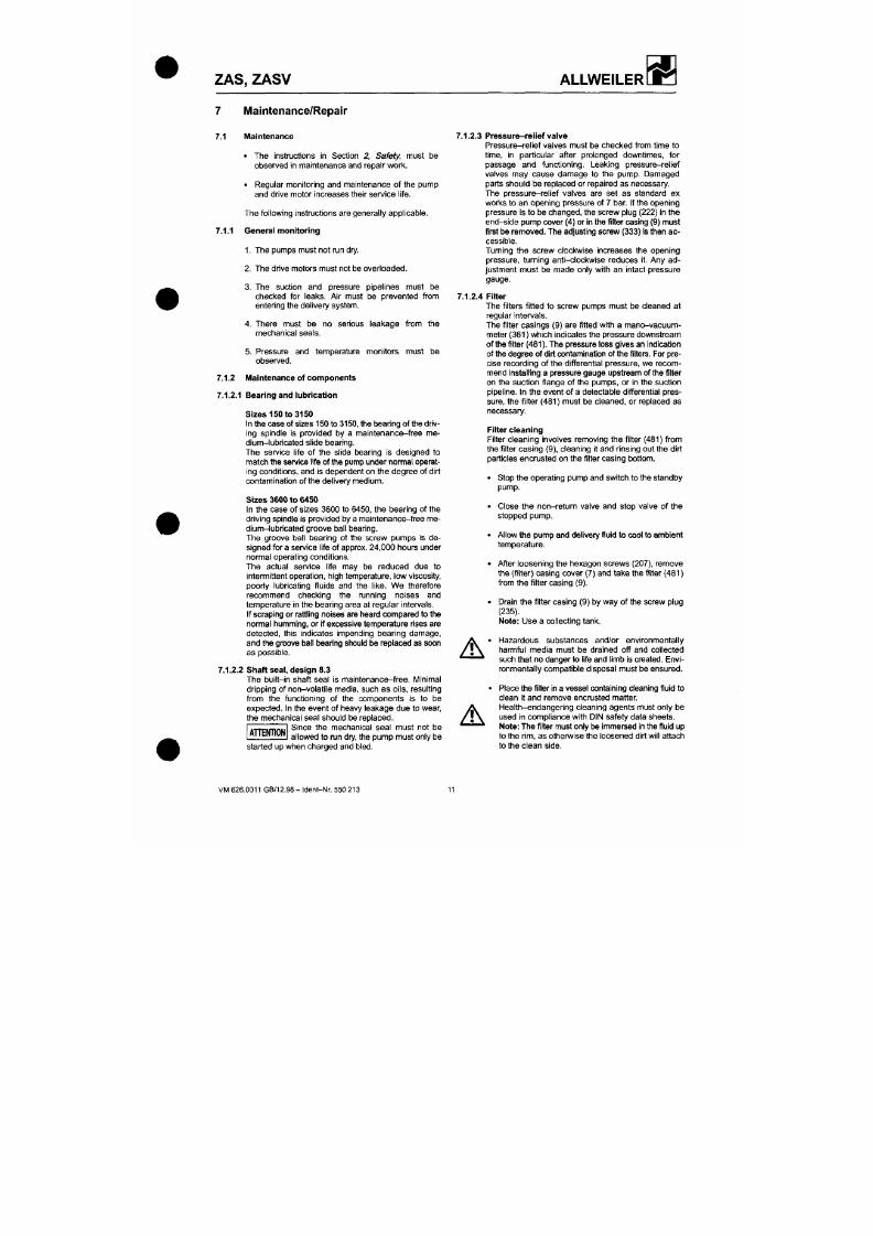
7/18/2019 M14 Thermal Fluid
http://slidepdf.com/reader/full/m14-thermal-fluid 112/486
7.1 Maintenance
• The instructions in Section 2, Safety, must be
observed in maintenance and repair work.
• Regular monitoring and maintenance of the pump
and drive motor increases their service life.
The following instructions are generally applicable.
7.1.1 Gene ral monitoring
1. The pumps must not run dry.
2. The drive motors must not be overloaded.
3. The suction a nd pressure p ipelines must be
checked for leaks. Air must be prevented from
entering the delivery system.
4. There m ust be no serious leakag e from the
mechanical seals.
5. Pressure an d temperature m onitors must be
observed.
7.1.2 IMaintenance of compo nents
7.1.2.1 Bearing and lubrication
Sizes 150 to 3150
7.1.2.3 Pressure-relief valve
Pressure-rel ief valves must be checked from time to
time, in particular after prolonged downtimes, for
passage and functioning. Leaking pressure-relief
valves may cause damage to the pump. Damaged
parts should be replaced or repaired as necessary.
The pressure-relief valves are set as standard ex
works to an opening pressure of 7 bar. If the opening
pressure is to be change d, the screw plug (222) in the
end- side pump cover (4) or in the filter casing (9) m ust
first be removed . The adjusting screw (333) is then ac
cessible.
Turning the screw clockwise increases the opening
pressure, turning anti-clockwise reduces it. Any ad
justment must be made only with an intact pressure
gauge.
7.1.2.4 Filter
The filters fitted to screw pumps must be cleaned at
regular intervals.
The filter casings (9) are fitted with a mano-vacuum-
meter (361) which indicates the pressure downstream
of the filter (481). The pressure loss gives an indication
of the degree of dirt contamination of the filters. For pre
cise recording of the differential pressure, we recom
mend installing a pressure gauge upstream of the filter
on the suction flange of the pumps, or in the suction
pipeline. In the event of a detectable differential pres
sure, the filter (481) must be cleaned, or replaced as
necessary.
ZAS, ZASV
ALLWEILER
• After allowing the filter to drip off from the clean side
7.2 Repair (Dismo unting and IVIounting Instructions)
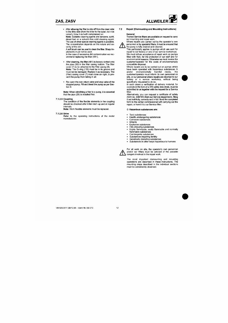
7/18/2019 M14 Thermal Fluid
http://slidepdf.com/reader/full/m14-thermal-fluid 113/486
to the dirty side (from the inner to the outer, not vice
versa ), blow it out with compress ed air.
Note:
Suitable cleaning agents are benzene, spirit,
diesel fuel or a solvent-free cold cleaning agent.
The use of other special cleaning agents Is possible.
The concentration depends on the nature and se
verity of the dirt.
A soft brush can be used to clean the filter. Sharp im
plements must not be used.
In the case of excessive dirt contamination we rec
ommend replacing the filter (481).
• After cleaning, the filter (481) is loosely slotted onto
the pipe (30) in the filter casing bottom. The filter
cover (7) is re-attached to the filter casing (9).
Note:
The O-ring (119) must be in its groove and
must not be damage d. Replace it as necessary. The
(filter) casing cover (7) must close air-tight, to pre
vent the pump from taking in air.
• Re- ope n the non-return valve and stop vatve of the
stopped pump. Fill and bleed the pump as per Sec
tion 6.
Note:
When retrofitting a filter to a pump , it is essential
that the pipe (29) is installed first.
7.1.2.5
Coupling
The condition of the flexible elements in the coupling
should be checked after initial start-up and at regular
intervals.
Note:
Worn flexible elements must be replaced.
A
General
Trained Service fitters are available on request to ca ny
out mounting and repair work.
Where repairs are carried out by the operator's own
perso nne l or by specialist fitters, it must be ensured th at
the pump is fully drained and cleaned.
This particulariy applies to pumps which are sent for
repair to our factory or one of our service workshops.
We must refuse acceptance of repair work on pumps
filled with fluid, for the protection of our staff and for
environm ental reasons. Otherwise we must invoice the
customer/operator for the costs of environmentally
compatible disposal.
Where repairs are to be carried out on pumps which
have been operated with hazardous substances (D
and/or environmentally harmful media, the
customer/operator must inform its own personnel on
site,
or our personnel where repairs are retumed to our
factory or a service workshop, without being
specifically requested to do so.
In such cases a verification of delivery material, for
exam ple in the form of a DIN safety data sheet, m ust be
subm itted to us together with the request for a Service
fitter.
Altematively, you can request a certificate of safety
(form no. 448/191) from our Service departm ent, filling
it out truthfully, correctly and in full. Send the completed
forni to the center commissioned with carrying out the
repair, or hand it to our Service fitter.
® Hazardous substances are:
ZAS, ZASV
ALLWEILER
7.2.1 Dismounting the screw pump
• Use an impleme nt to dismount mechanical seal
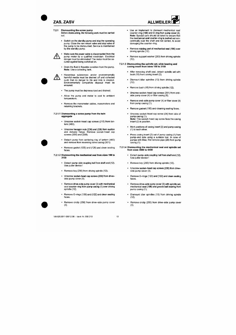
7/18/2019 M14 Thermal Fluid
http://slidepdf.com/reader/full/m14-thermal-fluid 114/486
Before dismounting, the following work must be carried
out:
• Switch on the standby pump and stop the operating
pump. Close the non-retum valve and stop valve of
the pump to be dismounted. Service is maintained
by the standby pump.
A
A
• Mal<e sure the power cable is disconnected from the
pump motor by a qualif ied electrician. Electrical
danger must be el iminated The motor must be se
cured against being switched on.
• Drain the fluid In f lowable condit ion from the pu mp.
Note:
Us e a collecting tank .
, . • Haza rdous substances and/or environme ntally
* \ harmful media must be drained of f and col lected
such that no danger to l i fe and l imb is created.
Environmentally compatible disposal must be
ensured.
• The pump must be depressur ized and drained.
• Allow the pump and motor to cool to amb ient
temperature.
• Remov e the manometer cables, manometers and
retaining brackets.
7.2.1.1 Dismounting a screw pump from the twin
coun ter-ring (186 ) and O-ring from pump cover (3).
Note:
Special care should be taken to ensure that
the mechanical seal coun ter-ring is pushed out con
centrically over the shaft and not canted, to avoid
damaging the counter-r ing.
• Remove rotating part of mechanical seal (186) over
driving spindle (12).
• Remove support washer (263) from driving spindle
(12).
7.2.1.3 Dismounting the spindle set, slide bearing and
casing insert from sizes 150 to 315 0
• After removing shaft
seal,
detach spindle set with
bush (10) from c asing insert (2).
• Dismount idler spindles (13) from driving spindle
(12).
• Remove bush (10) from driving spindle (12).
• Unscrew socket-head cap screws (201) f rom en d-
side pump c over (4) or fi l ter casing (9).
• Remove en d-s ide pump cover (4) or f i lter cover (9)
from pump casing (1).
• Remove gasket (100) and cleaning sealing faces.
• Unscrew soc ket- hea d cap screw (24) from side of
ZAS,
ZASV
ALLWEILER
• Press driving spindle (12) with groove ball bearing
7.2.2
Mounting the screw pum p
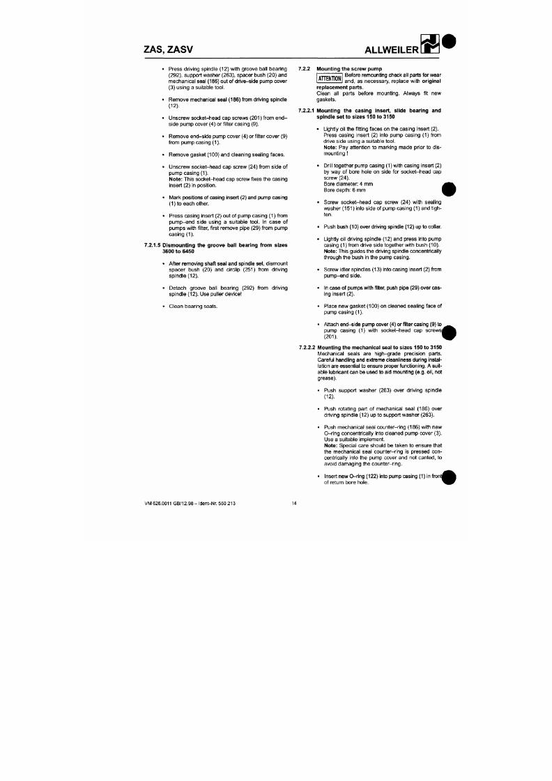
7/18/2019 M14 Thermal Fluid
http://slidepdf.com/reader/full/m14-thermal-fluid 115/486
(292), support washer (263), spacer bush (20) and
mec hanica l seal (186) out of drive-side pump cover
(3) using a suitable
tool.
• Rem ove mechanical seal (186) from driving spindle
(12).
• Unscrew socl<et-head cap screws (201) f rom en d -
side pu mp cover (4) or fi l ter casing (9).
• Rem ove end -side pump cover (4) or f i lter cover (9)
from pump casing (1).
• Rem ove gasket (100) and cleaning sealing face s.
• Unscrew socket-head cap screw (24) f rom side of
pump casing (1).
Note: This socket-head cap screw fixes the casing
Insert (2) in position.
• M ark positions of casing insert (2) and pump casing
(1)to each other.
• Press casing insert (2) out of pump casing (1) from
pump-end side using a sui table
tool.
In case of
pumps with f i l ter, f irst remove pipe (29) from pump
casing (1).
7.2.1.5 Dismounting the groove bal l bearing from sizes
3600 to 645 0
• After removing shaft seal and spindle set, dismount
Before remounting check all parts for wear
and, as necessary, replace with original
T T E N T I O N
replacement parts.
Clean all parts before mounting. Always fit new
gaskets.
7.2.2.1 Mounting the casing insert, slide bearing and
spindle set to sizes 15 0 to 3150
• Lightly oil the f itting faces on the casing insert (2).
Press casing insert (2) into pump casing (1) from
drive side using a suitable tool.
Note: Pay attention to marking made prior to dis
mounting
• Dri ll together pump ca sing (1) with casing insert (2)
by way of bore hole on side for socket-head cap
screw (24).
Bore diameter: 4 mm
Bore depth: 6 mm
• Screw soc ket-h ead cap screw (24) with sealing
washer (151) Into side of pump casing (1) and tigh
ten.
• Push bush (10) over driving spindle (12) up to collar.
• Lightly oil driving spindle (12) and press into pump
casing (1) from drive side together with bush (10).
Note: This guides the driving spindle concentrically
through the bush in the pump casing.
ZAS, ZASV
ALLWEILER
• Attach pump cover (3) with new O-ring (120) and
centrically into the pump cover and not canted, to
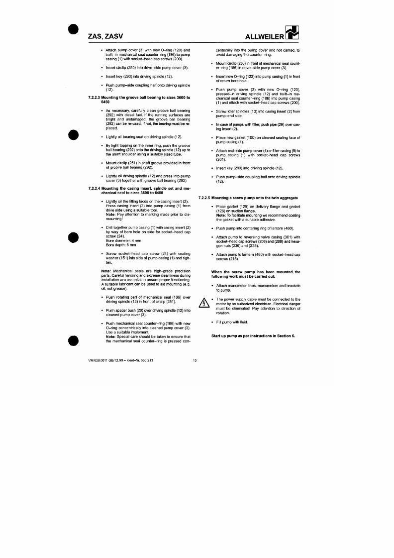
7/18/2019 M14 Thermal Fluid
http://slidepdf.com/reader/full/m14-thermal-fluid 116/486
bu ilt- in mechanical seal counter-ring (186) to pum p
casing (1) with socket-head cap screws (200).
• Insert circl ip (250) into drive-side pum p cover (3).
• Insert key (290) into drivin g spindle (12).
• Push pump -side coupling half onto driving spindle
(12).
7.2.2.3 Mounting the groove ball bearing to sizes 3600 to
6450
• As necessary, carefully clean groove ball bearing
(292) with diesel
fuel.
If the mnning surfaces are
bright and undamaged, the groove ball bearing
(292) can be re-use d. If not, the bearing must be re
placed.
• Lightly oil bearing seat on driving spindle (12).
• By l ight tapping on the inner ring, push the groove
ball bearing (292) onto the driving spindle (12) up to
the shaft shoulder using a suitably sized tube.
• Mo unt circl ip (251) in shaft groove provided in front
of groove ball bearing (292).
• Lightly oil driving spindle (12) and press into pump
cover (3) together with groove ball bearing (29 2).
7.2.2.4 Mounting the casing insert, spindle set and me
avoid damaging the coun ter-r ing.
• M oun t circlip (250) in front of mechanical seal count
er-r ing (186) in dr ive-sid e pump cover (3) .
• Insert new 0-rin g (122 ) into pump casing (1) in front
of return bore hole.
• Push pump cover (3) with new 0-r in g (120),
pressed-in driving spindle (12) and built- in me
chanical seal counter-ring (186) into pump casing
(1) and attach with socket-head cap screws (200).
• Scre w idler spindles (13) into casing insert (2) from
pump-end side.
• In case of pumps with filter, push pipe (29) over cas
ing insert (2).
• Place new gasket (100) on cleaned sealing face of
pump casing (1).
• Attac h end-side pu mp cover (4) or filter casing (9) to
pump casing (1) wi th socket-head cap screws
(201).
• Insert key (290) into driving spindle (12).
• Push pum p-side coup ling half onto driving spindle
(12).
ZAS, ZASV ALLWEILER
7.3 Replaceme nt parts/spare parts
The parts marked with footnote ® in the parts list can be
7/18/2019 M14 Thermal Fluid
http://slidepdf.com/reader/full/m14-thermal-fluid 117/486
provided as replacement/spare parts.
The casing insert (2) with spindles (12) and (13) are
available only as a complete spare part set.
However, for operational safety reasons, we recom
mend you always stock a complete car t r idge-uni t or
standby pump.
The adv antage Is that in the event of a fault or damage
the standby unit can replace the non-functioning unit
quickly a nd w ithout great effort.
When order ing spare and replacement parts, besides
th e
part number, denomination
a nd
quantity,
th e
fol
lowing should also be quoted:
Pump abbreviation,
Pump number,
Year of construction.
This information is engraved on the rating plate of the
pump.
ZAS,
ZASV
ALLWEILER
8 Operating Faults, Causes and Remed ial Action
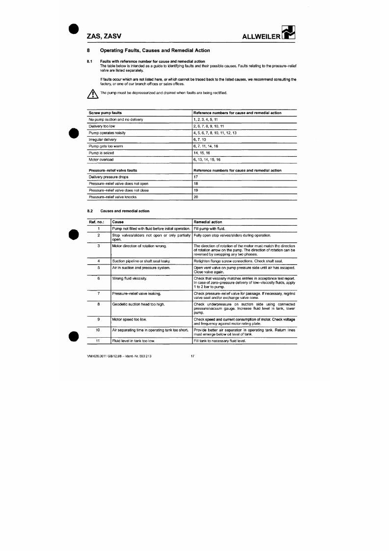
7/18/2019 M14 Thermal Fluid
http://slidepdf.com/reader/full/m14-thermal-fluid 118/486
8.1 Faults with refere nce number for cause and rem edial action
The table below is intended as a g uide to identi lying faults and their possible causes. Faults relating to the pressure-relief
valve are l isted separately.
If faults occur which are not l isted here, or which cannot be traced back to the l isted causes, we recommend consult ing the
factory, or one of our branch offices or sales offices.
'iX The pump mus t be depressurlzed and drained when faults are being rectified.
A
Screw pump faults
No pump suction and no delivery
Delivery too low
Pump operates noisi ly
Irregular delivery
Pum p gets too warm
Pump is seized
Motor overload
Pressure-rel ief valve faults
Delivery pressure drops
Pressure-relief valve does not open
Reference numbers for cause and remedial action
1,2,3,4,5,11
2 , 6 , 7 , 8 , 9 , 1 0 , 1 1
4 , 5 , 6 , 7 , 8 , 1 0 , 1 1 , 12,13
6,7,10
6 , 7 , 1 1 , 1 4 , 1 6
14 , 15, 16
6 ,13 , 14 ,15 ,16
Reference numbers for cause and remedial action
17
18
ZAS, ZASV
ALLWEILER
12 Flow rate in suction and pressure pipelines too
high.
Flow rate in suction pipe line must not exce ed m ax. 1 m/s, an d
in pressure pipeline max. 3 m/s.
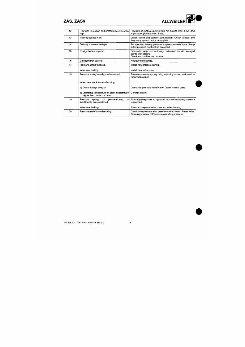
7/18/2019 M14 Thermal Fluid
http://slidepdf.com/reader/full/m14-thermal-fluid 119/486
13
14
15
16
17
18
19
20
Motor speed too
high.
Delivery pressure too
high.
Foreign bodies in pump.
Damaged ball bearing.
Pressure spring fatigued.
Valve seat leaking.
Pressure spring heavily pre-tensioned.
Valve cone stuck in valve housing .
a) Due to foreign body or
b) Operating temperature of plant substantial ly
higher than q uoted on order.
Pressure spring not pre-tensioned, or
insufficiently pre-tensioned.
Valve seat leaking.
Pressure-relief valve knocking.
Check speed and current consumpt ion. Check vol tage and
frequen cy ag ainst mo tor rating plate.
Set specif ied delivery pressure via pressu re-relief valve. Pump
outlet pressure must not be exceeded.
Dismantle pump, remove foreign bodies and smooth damaged
points with oilstone.
Che ck s uction f il ter and strainer.
Replace ball bearing.
Install new pressure spring.
Install new valve cone.
Release pressure spring using adjusting screw, and reset to
required pressure.
(
Dismant le pressure-rel ief
valve.
Clean internal parts.
Con sult factory.
Tum adjusting screw to right unti l required operating pressure
is reached.
Rework or replace valve cone and valve housing.
Check overpressure with pressure valve closed. Reset valve.
Opening pressure 10 % above operating pressure.
ZAS, ZASV
ALLWEILER
Sectional drawing
Series Z AS w ithout f il ter
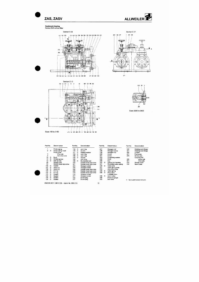
7/18/2019 M14 Thermal Fluid
http://slidepdf.com/reader/full/m14-thermal-fluid 120/486
Sect ion A-B
441 124 355 123 440 204 356 108 206 125 236 900 290 216 231
/ / / / / /
• / / /
Section E-F
227 156 107 1 301 126
• g ^ r . r , - n t r 7 r , / i r i l f 4 U ^ - H | F -
238 100 222 142 333 340 331 330 120 200 263 217 231 901 910
Sect ion C-D
ZAS, ZASV
ALLWEILER
Sectional drawing
Series ZAS with filter
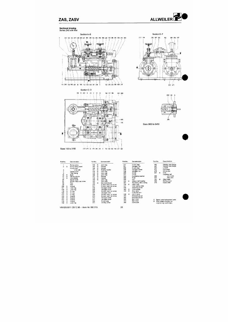
7/18/2019 M14 Thermal Fluid
http://slidepdf.com/reader/full/m14-thermal-fluid 121/486
Section A- B
7 362 146 143 207 238 208 441 301 206 124 204 356 108 440 123 206 125 236 216 360
i ; i i I I / I I 1 i I I I i I , I
Section E-F
22 7 156 355 107 126 152 361 364 157
M i l '
119 235 159 962 431 30 100 142 333 340 331 330 1 120 200 263 250 900 217
Section C-D
151 13 201 9 29 2 12 10 160 122 186 901 290
ZAS, ZASV
ALLWEILER
Sectional drawing
Series ZASV without filter
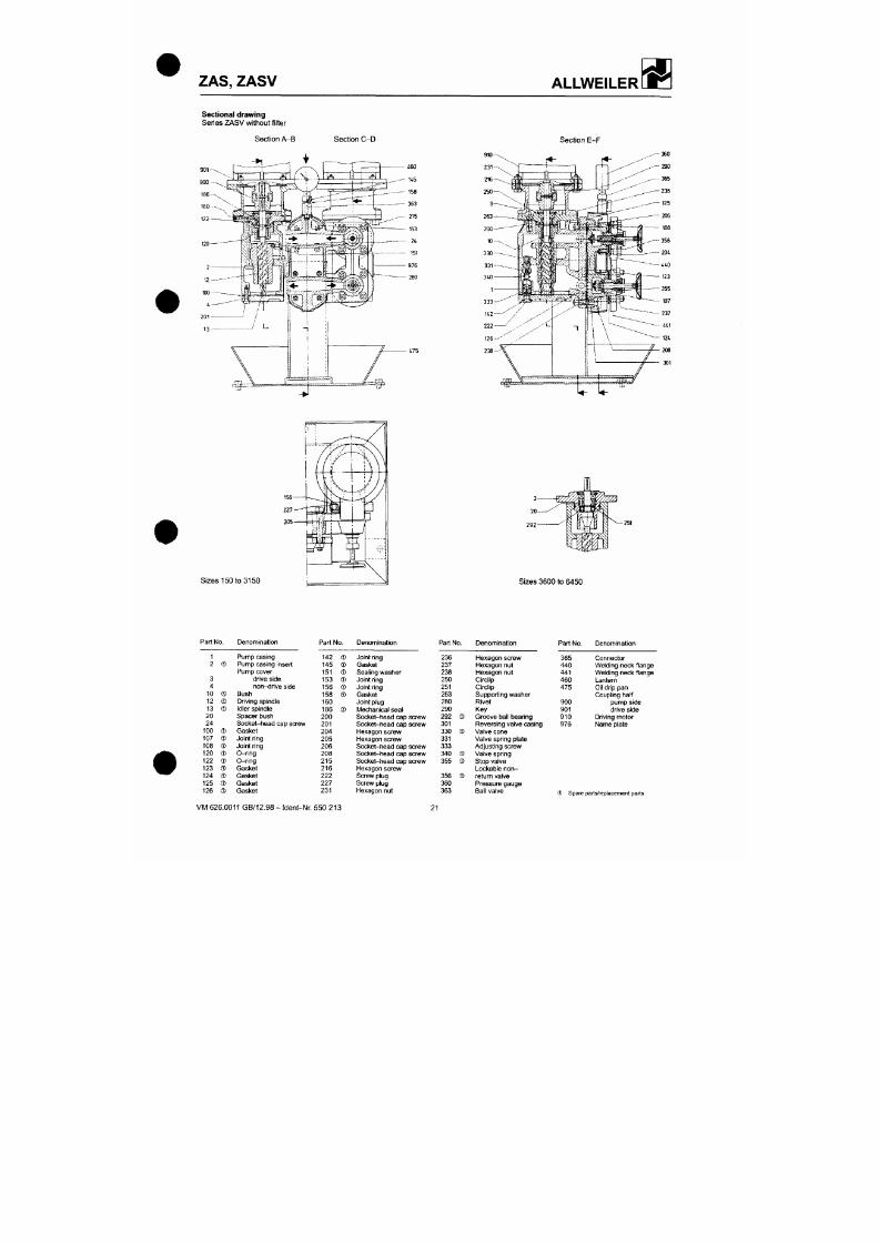
7/18/2019 M14 Thermal Fluid
http://slidepdf.com/reader/full/m14-thermal-fluid 122/486
Section A -B
Section C-D
Section E-F
rx^
ZAS, ZASV
ALLWEILER
W ß
Sectional drawing
Series ZASV with filter
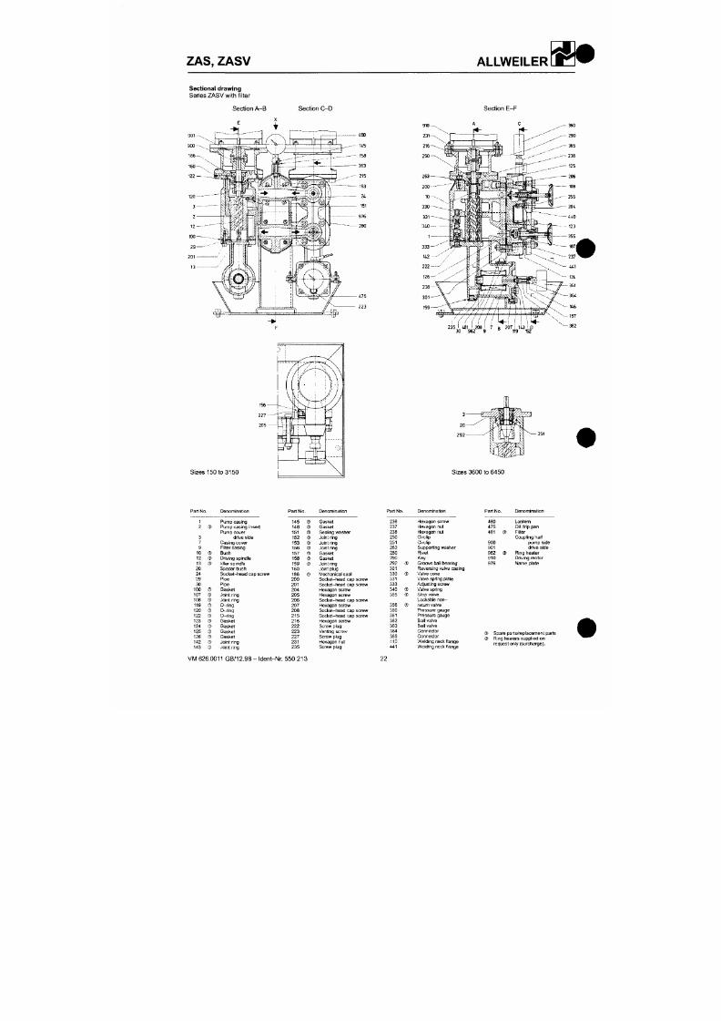
7/18/2019 M14 Thermal Fluid
http://slidepdf.com/reader/full/m14-thermal-fluid 123/486
Section A-B Section C-D
Section E-F
235 481 i 208
^
7 R 207 i 143
•
D
30 962 9 ° 119 152
#
V
M
6
0
G
1
9
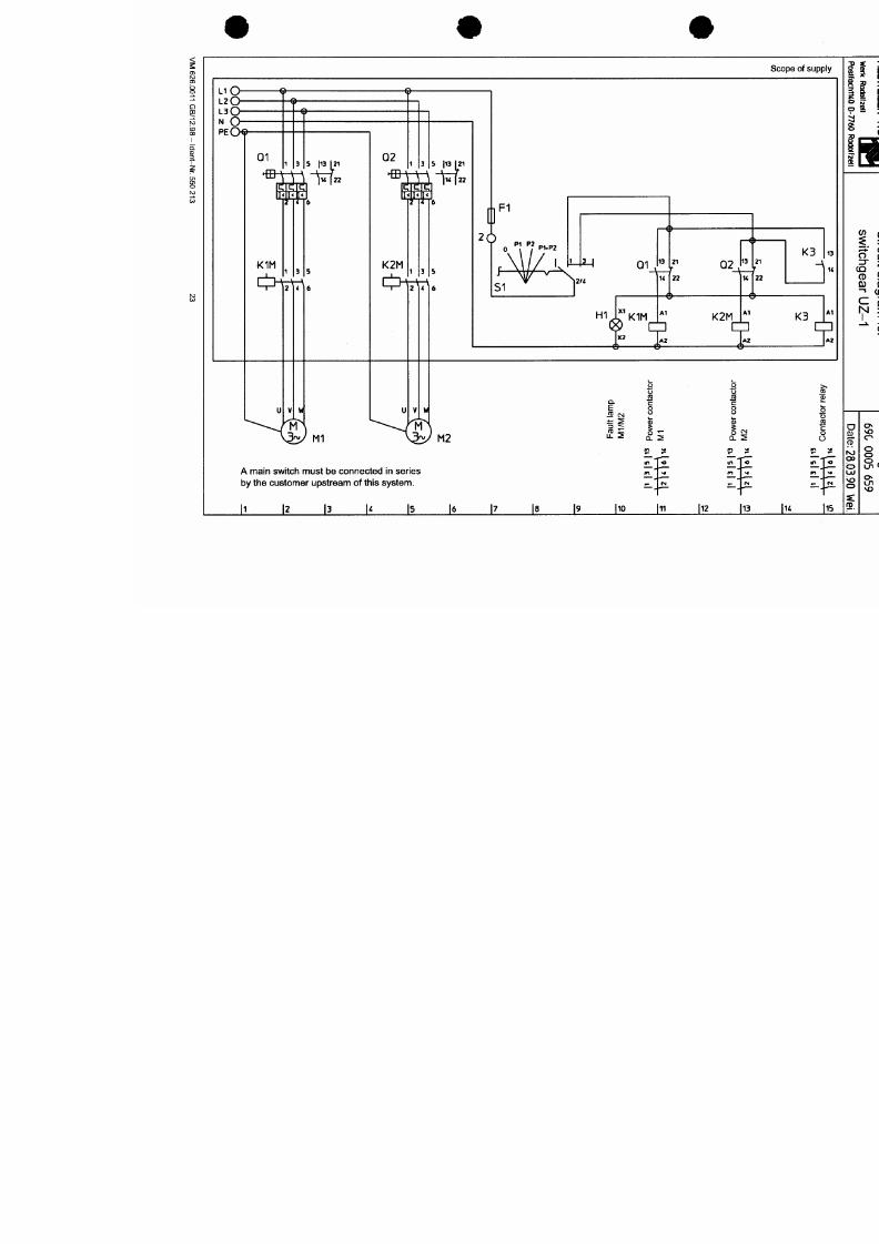
7/18/2019 M14 Thermal Fluid
http://slidepdf.com/reader/full/m14-thermal-fluid 124/486
z
d
u
n
J
O
U
O
J
M
j
o
o
u
a
M
d
N
5
2
2
ZAS, ZASV ALLWEILER
W ß
7/18/2019 M14 Thermal Fluid
http://slidepdf.com/reader/full/m14-thermal-fluid 125/486
#
A R M A T U R E N
Betriebs- und Montageanleitung
Durchgangs-Stellventile - STEVl® 440 /
441,
445 / 446
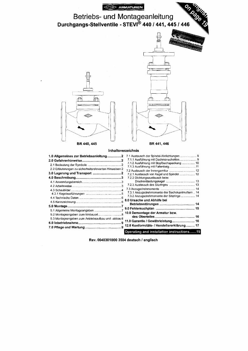
7/18/2019 M14 Thermal Fluid
http://slidepdf.com/reader/full/m14-thermal-fluid 126/486
: ^ l T f e > A R M A T U R E N
Betriebs- und Montageanleitung
DG-Stellventile - STEVI® 440 / 441, 445 / 446
1.0 A l lgem eines zur B et r iebsan le i tung
Diese Betriebsanleitung gilt als Anweisung, d ie Armaturen sicher zu montieren und zu
warten. Bei Schwierigkeiten, die nicht mit Hilfe der Betriebsanleitung gelöst werden
können,
nehmen Sie Kontakt mit dem Lieferant oder Hersteller auf.
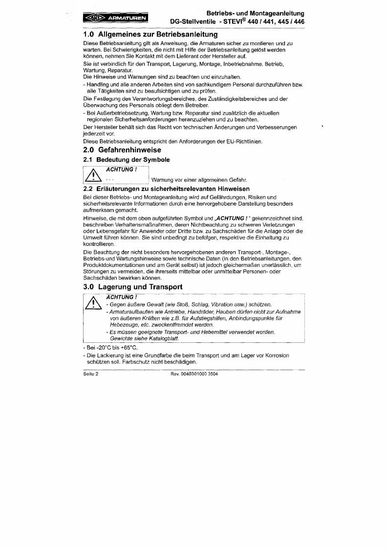
7/18/2019 M14 Thermal Fluid
http://slidepdf.com/reader/full/m14-thermal-fluid 127/486
Sie ist verbindlich für den Transport, Lagerung, IVIontage, Inbetriebnahme, Betrieb,
Wartung, Reparatur
Die Hinweise und Warnungen sind zu beachten und einzuhalten.
- Handling und alle anderen Arbeiten sind von sachkundigem Personal durchzuführen bzw.
alle Tätigkeiten sind zu beaufsichtigen und zu prüfen.
Die Festlegung des Verantwortungsbereiches, des Zuständigkeitsbereiches und der
Überwachung des Personals obliegt dem Betreiber.
- Bei Außerbetriebsetzung, Wartung bzw. Reparatur sind zusätzlich die aktuellen
regionalen Sicherheitsanforderungen heranzuziehen und zu beachten.
Der Hersteller behält sich das Recht von technischen Änderungen und Verbesserungen
jederzeit vor.
Diese Betriebsanleitung entspricht den Anforderungen der EU-Richtlinien.
2.0 Gefahrenh inweise
2.1 Bedeutung der Symbole
ACHTUNG
V
A
Warnung vor einer allgemeinen Gefahr
g Q * > A R M A T U R E N
Betriebs- und Montageanleitung
DG -Stellventile - STEVI® 440 / 441, 445 / 446
4 .0 Be s c h r e ib u n g
4.1 Anwendungsbereich
Armaturen werden zum „Regeln von flüssigen, gasförmigen und dampfförmigen Medien in
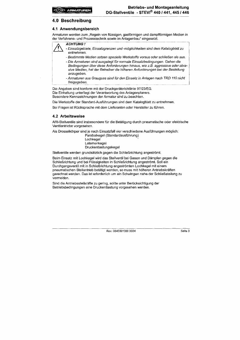
7/18/2019 M14 Thermal Fluid
http://slidepdf.com/reader/full/m14-thermal-fluid 128/486
der Verfahrens- und Prozesstechnii^ sowie im Anlagenbau" eingesetzt.
A
ACHTUNG
- Einsatzgebiete, Einsatzgrenzen und -mögliclikeiten sind dem Kataiogblatt zu
entnehmen.
- Bestimmte Medien setzen spezieile Werkstoffe voraus oder schiießen sie aus.
- Die
Armaturen
sind
ausgelegt für normale
Einsatzbedingungen.
Gehen
die
Bedingungen über diese Anforderungen hinaus, wie z.B. aggressive oder abra
sive l\Aedien, hat der Betreiber die höheren Anforderungen bei der Bestellung
anzugeben.
- Armaturen aus Grauguss sind für den Einsatz in Anlagen nach TRD 110 nicht
freigegeben.
Die Angaben sind konform mit der Druckgeräterichtlinie 97/23/EG.
Die Einhaltung unterliegt der Verantwortung des Anlagenplaners.
Besondere Kennzeichnungen der Armatur
sind
zu beachten.
Die Werkstoffe der Standard-Ausführungen sind dem Katalogblatt zu entnehmen.
Bei Fragen ist Rücksprache mit dem Lieferanten oder Hersteller zu füh ren.
A R M A T U R E N
Betriebs- und Montageanleitung
DG -Stellventile - STEVI® 440 /
441,
445 / 446
4.3 Schaubilder
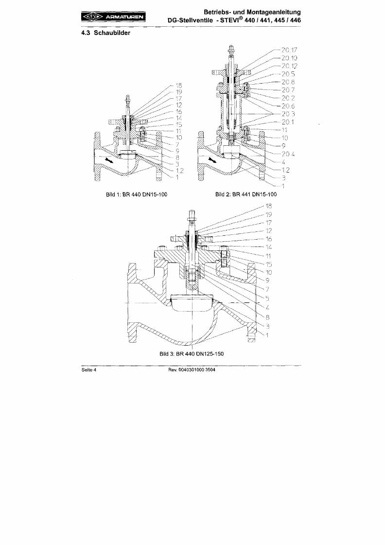
7/18/2019 M14 Thermal Fluid
http://slidepdf.com/reader/full/m14-thermal-fluid 129/486
« K J y § > A R M A T U R E N
Betriebs- und Montageanleitung
DG-Stellventile - STEVI® 440 / 441 , 445 / 446
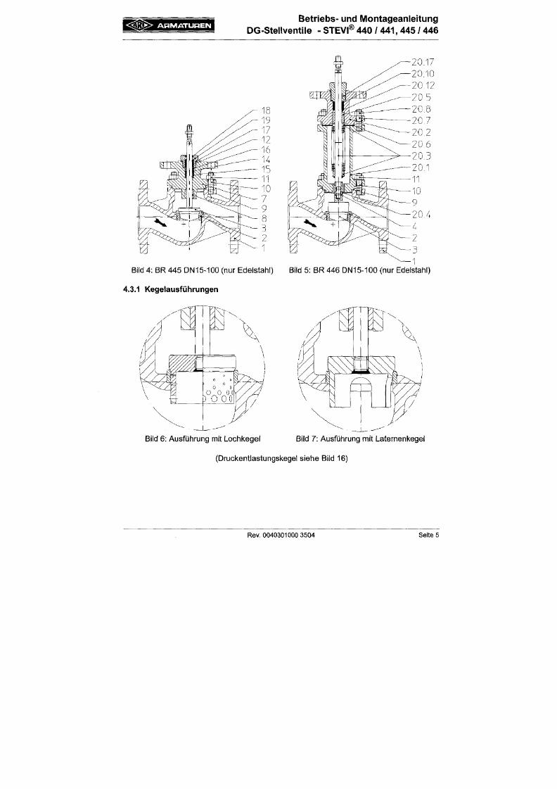
7/18/2019 M14 Thermal Fluid
http://slidepdf.com/reader/full/m14-thermal-fluid 130/486
A R M A T U R E N
Betriebs- und Montageanleitung
DG-Stellventile - STEVI® 440 /
441,
445 / 446
4.4 Technische Daten
wie z.B.
- Hauptabmessungen ,
- Druck-Temperatur-Zuordnungen, usw.
sind dem Kata logbla tt zu entnehm en.
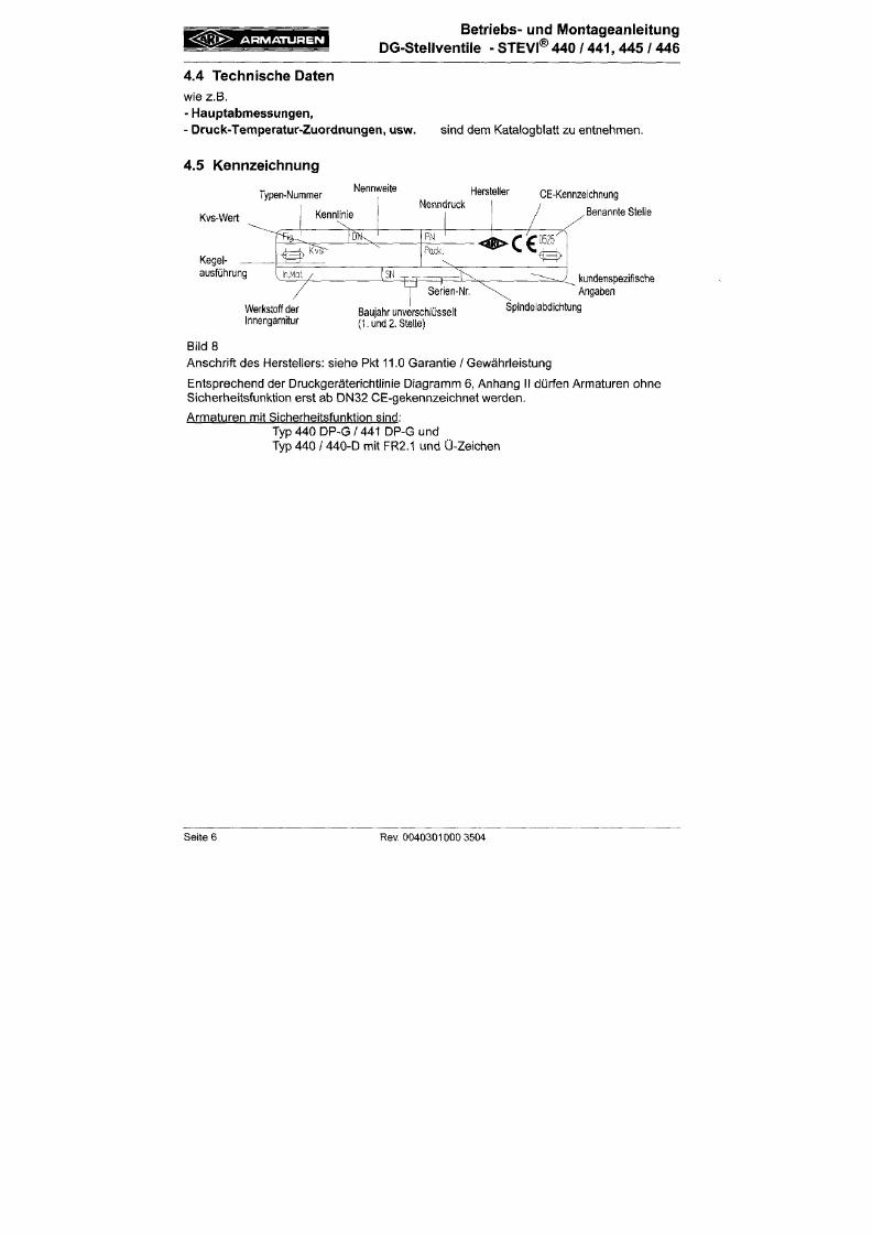
7/18/2019 M14 Thermal Fluid
http://slidepdf.com/reader/full/m14-thermal-fluid 131/486
4.5 Kennzeichnung
Typen-Nummer
Kvs-Wert
Kegel
ausführung
Werkstoff der
Innengarnitur
Nennweite
Hersteller
CE-Kennzeichnung
Benannte Stelle
kundenspezifische
Angaben
Baujahr unverschlüsselt
(1. und 2. Stelle)
Spindelabdichtung
B i l d s
Ans chri f t de s Herstel lers: siehe Pkt 11.0 Garan t ie / Gew ährleistung
Entsprechend der Druckgeräter icht l in ie Diagramm 6, Anhang I I dürfen Armaturen ohne
Sicherhei tsfunkt ion erst ab DN 32 CE -gekennzeichnet werde n.
Armaturen mit Sicherhei tsfunkt ion sind:
A R M A T U R E N
Betriebs- und M ontageanleitung
DG -Stellventile - STEVI® 440 / 441, 445 / 446
5 .0 Mont age
5.1 Allgemeine Montageangaben
Neben den allgemeingültigen Montagerichtlinien sind folgende Punkte zu beachten;
7/18/2019 M14 Thermal Fluid
http://slidepdf.com/reader/full/m14-thermal-fluid 132/486
A
ACHTUNG
- Flanschabdeckungen, falls vorhanden, entfernen.
- Der Innenraum von A rmatur und Rohrleitung muss frei von Fremdpartikeln sein.
-
Einbaulage
in
Bezug
auf
Durchströmung
beachten,
siehe Kennzeichnung
auf
der Armatur
- Dampfieitungssysteme sind so
auszulegen,
dass Wasseransammlungen
vermieden
werden.
- Die Rohrleitungen so verlegen, dass schädliche Schub-, Biege- und
Torsionskräfte ferngehalten
werden.
- Bei
Bauarbeiten Armaturen
vor
Verschmutzung
schützen.
-
Anschlussflansche müssen
übereinstimmen.
-Armaturaufbauten wie
A ntriebe,
Handräder, Hauben dürfen nicht
zur A ufnahme
von
äußeren Kräften
wie
z.B.
Aufstiegshilfen,
Anbindungspunkte
für
Hebezeuge etc. zweckentfremdet werden.
- Für
Montagearbeiten müssen geeignete
Transport-
und Hebemittel verwendet
werden.
Gewichte siehe Katalogblatt.
-
Spindelgewinde
und
Spindelschaft müssen farbfrei
bleiben.
A R M A T U R E N
Betriebs- und Montageanleitung
DG -Stellventile - STEVI® 440 /
441,
445 / 446
5.2 IVIontageangaben zum Einbauort
Die Einbaustelle soll gut zugänglich sein und genügend Freiraum zur Wartung und zum
Abnehmen der S tellantriebe aufweisen. Vor und h inter dem Stellventil sind
Handabsperrventile vorzusehen, die Wartungs- und Reparaturarbeiten am Stellventil
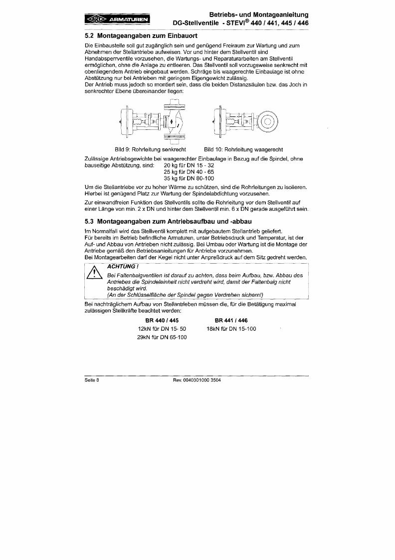
7/18/2019 M14 Thermal Fluid
http://slidepdf.com/reader/full/m14-thermal-fluid 133/486
ermöglichen, ohne die Anlage zu entleeren. Das Stellventil soll vorzugsweise senkrecht mit
obenliegendem Antrieb eingebaut
werden.
Schräge bis waagerechte Einbaulage ist ohne
AbStützung nur bei Antrieben mit geringem Eigengewicht zulässig.
Der Antrieb muss jedoch so m ontiert sein, dass die beiden Distanzsäulen bzw. das Joch in
senkrechter Ebene übereinander liegen:
Bild 9: Rohrleitung senkrecht Bild 10: Rohrleitung waagerecht
Zulässige Antriebsgewichte bei waagerechter Einbaulage in Bezug auf die Spindel, ohne
bauseitige Abstützung, sind: 20 kg für DN 1 5 -3 2
25 kg für DN 40 - 65
35 kg für DN 80-100
Um die Stellantriebe vor zu hoher Wärme zu schützen, sind die Rohrleitungen zu isolieren.
A R M A T U R E N
Betriebs- und Montageanleitung
DG -Steilventile - STEVI® 440 / 441, 445 / 446
6 .0 Inbe t r i ebnahme
ACHTUNG
- Vorder
Inbetriebnahme sind die Angaben
zu
Werkstoff, Druck, Temperatur und

7/18/2019 M14 Thermal Fluid
http://slidepdf.com/reader/full/m14-thermal-fluid 134/486
A
Strömungsrichtung zu
übe rprüfen.
- Grundsätzlich sind die regionalen Sicherheitsanweisungen e inzuhalten.
-
Rückstände
in
Rohrleitungen und Armaturen (wie Schmutz, Schweißperlen,
usw.) führen
zu
Undichtigkeiten bzw. Beschädigungen.
-
Beim Betrieb
m it
hohen
(> 50 "C) oder
tiefen
(<0°C)
Medientemperaturen
besteht Verletzungsgefahr
be i
Berühren
der
Armatur.
Ggf Warnhinweise oder Isolierschutz
anbringen
Vor Jeder Inbetriebnahme einer Neuanlage
bzw.
Wiederinbetriebnahme einer
Anlage
nach Reparaturen
oder
Umbauten
is t
sicherzustellen:
- Der
ordnungsgemäße Abschluss aller
A rbeiten
- Die
richtige Funktionsstellung
der A rmatur
-
Schutzvorrichtungen sind angebracht.
7 .0 P f l ege und W ar t un g
Die Wartung und Wartungsintervalle sind entsprechend den Anforderungen vom Betreiber
festzulegen.
7.1 Austausch der Spindel-Abdichtungen
A R M A T U R E N
Betriebs- und M ontageanleitung
DG -Steilventile - STEVI® 440 /
441,
445 / 446
7.1.2 Ausführung mit Stopfbuchspackung
Die Stopfbuchspackung (Pos. 23) ist nicht wartungsfrei.
Bei auftretenden Undichtigkeiten sofort stufenweise die Verschraubung (Pos. 25) bis zur
Dichtheit der Packung (Pos. 23) anziehen.
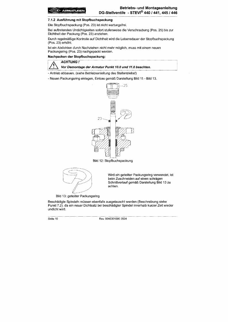
7/18/2019 M14 Thermal Fluid
http://slidepdf.com/reader/full/m14-thermal-fluid 135/486
Durch regelmäßige Kontrolle auf Dichtheit wird die Lebensdauer der Stopfbuchspackung
(Pos. 23) erhöht.
Ist ein Abdichten durch Nachziehen nicht mehr möglich, muss mit einem neuen
Packungsring (Pos. 23) nachgepackt werden.
Nachpacken der Stopfbuchspackung:
A
ACHTUNG
Vor Demontage der Armatur Punkt 10.0
und
11.0 beachten.
• Antrieb abbauen, (siehe Betriebsanleitung des Stellantriebs )
• Neuen Packungsring einlegen, Einbau gemäß Darstellung Bild 11 - Bild 13.
A R M A T U R E N
Betriebs- und Montageanleitung
DG -Stellventile - STEVI® 440 /
441,
445 / 446
7.1.3 Ausführung mit Faltenbalg
Bei Undichtigkeiten an der Spindel liegt ein Defekt des eingebauten Faltenbalges
(Pos. 20.3) vor. Zunächst kann durch leichtes Anziehen der Verschraubung (Pos. 20.17)
eine ausreichende Dichtheit erzielt werde n.
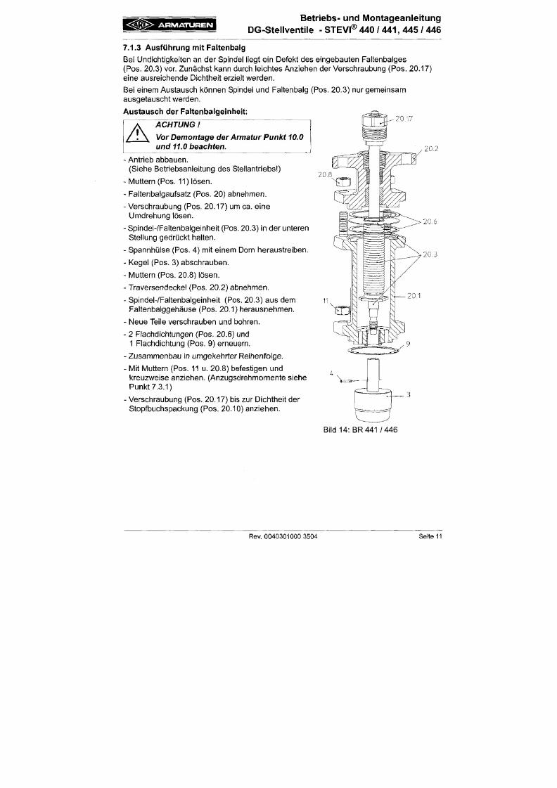
7/18/2019 M14 Thermal Fluid
http://slidepdf.com/reader/full/m14-thermal-fluid 136/486
Bei einem Austausch können Spindel und Faltenbalg (Pos. 20.3) nur gemeinsam
ausgetauscht werden.
Austausch der Faltenbalgelnheit:
A
ACHTUNG
Vor Demontage der Armatur
Punkt
10.0
und
11.0
bea chten.
20,17
- Antrieb abbauen.
(Siehe Betriebsanleitung des Stellantriebs )
- Muttern (Pos. 11) lösen.
- Fa ltenbalgaufsatz (Pos. 20) abnehmen.
-Verschraubung (Pos. 20.17) um ca. eine
Umdrehung lösen.
- Spindel-ZFaltenbalgeinheit (Pos. 20.3) in der unteren
Stellung gedrückt halten.
- Spannhülse (Pos. 4) mit einem Dorn heraustreiben.
- Kegel (Pos. 3) abschrauben.
20.8
20.2
20.6
20.3
A R M A T U R E N
Betr iebs- und Montageanlei tung
DG -Stel lventi le - STEVi® 440 / 441 , 445 / 446
7.2 Austausch der Innengarni tur
7.2.1 Austausch von Kegel und Spindel
ACHTUNG
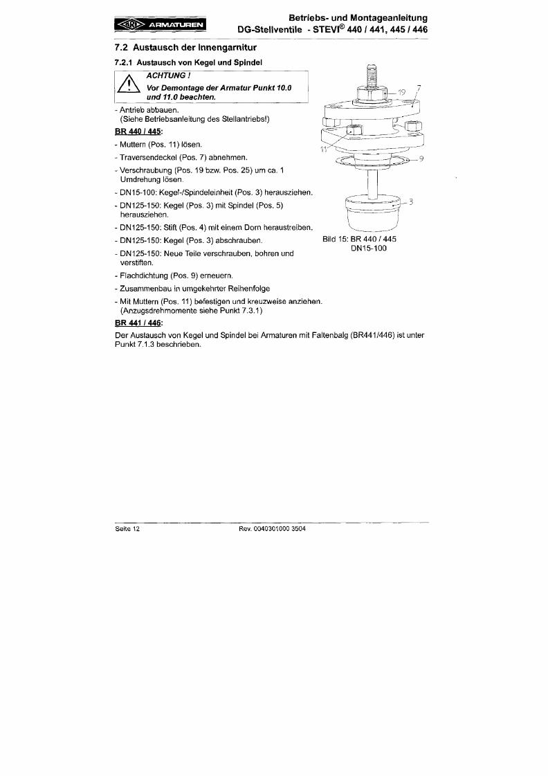
7/18/2019 M14 Thermal Fluid
http://slidepdf.com/reader/full/m14-thermal-fluid 137/486
A
Vor Demontage
der Armatur
Punkt 10.0
und 11.0 bea chten.
- Antrieb abbauen.
(Siehe Betriebsanleitung des Stellantriebs )
BR
440
/
445:
- Muttern (Pos. 11) lösen.
- Traversendeckel (Pos. 7) abnehmen.
- Verschraubung (Pos. 19 bzw. Pos. 25) um ca. 1
Umdrehung lösen.
- DN15-100: Kegel-ZSpindeleinheit (Pos. 3) herausziehen.
- DN125-150: Kegel (Pos. 3) mit Spindel (Pos. 5)
herausziehen.
- DN125-150: Stift (Pos. 4) m it einem Dorn heraustreiben.
- DN125-150: Kegel (Pos. 3) abschrauben.
- DN125-150: Neue Teile verschrauben, bohren und
verstiften.
Bild 15: BR 44 0/ 4 45
DN15-100
<^3>>
A R M A T U R E N
Betriebs- und Montageanleitung
DG-Steliventile - STEVI® 440 / 441, 445 / 446
7.2.2 Dichtungsaustausch beim Druckentlastungskegel
ACHTUNG
Vor Demontage der Armatur
Punkt
10.0
und
11.0
beachten.
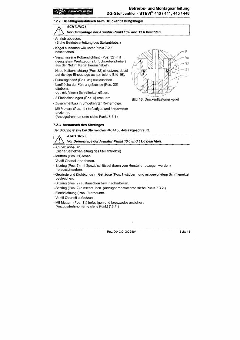
7/18/2019 M14 Thermal Fluid
http://slidepdf.com/reader/full/m14-thermal-fluid 138/486
A
•
Antrieb abbauen.
(Siehe Betriebsanleitung des Stellantriebs )
• Kegel ausbauen wie unter Punkt 7.2.1
beschrieben.
•
Verschlissene Kolbendichtung (Pos. 32) mit
geeignetem W erkzeug (z.B. Schraubendreher)
aus der Nut im Kegel heraushebeln.
-
Neue Kolbendichtung (Pos. 32) einsetzen , dabei
aufrich tige Einbaulage achten (siehe Bild 16).
• Führungsband (Pos. 31) austauschen.
- Lauffläche der Führungsbuchse (Pos. 30)
säubern;
ggf. mit feinem Schleifmittel glätten.
-
2 Flachdichtungen (Pos. 9) erneuern.
-
Zusammenbau in umgekehrter Re ihenfolge.
• M it Muttern (Pos. 11) befestigen und kreuzweise
anziehen.
Bild 16: Druckentlastungskegel
A R M A T U R E N
Betriebs- und Montageanleitung
DG-Stellventile - STEVI® 440 / 441, 445 / 446
7.3 Anzugsdrehimomente
7.3.1 Anzugsdrehmomente der Sechskantmuttern
M 1 0 = 1 5 - 3 0 N m
7/18/2019 M14 Thermal Fluid
http://slidepdf.com/reader/full/m14-thermal-fluid 139/486
M 12 = 3 5 - 5 0 Nm
M 16 = 80-1 20N m
7.3.2 Anzugsdrehmomente der Sitzringe
DN 15/20
DN
25/ 32
DN
40 /
50
DN65
DN80
DN100
=
=
=
=
=
=
100 Nm
150 Nm
350 Nm
480 Nm
660 Nm
980 Nm
/
A ntriebsaufbau siehe Betriebsanleitung
für betreffenden A ntrieb
8.0 Ursache und Abh i l f e be i Be t r i ebss tö rungen
• C S I S ^
A H M A T U H E I M
Betriebs- und Montageanleitung
DG-Stellventile - STEVI® 440 /
441,
445 / 446
9.0 Feh lersuchp lan
ACHTUNG
- vor Mo ntage- und Reparaturarbeiten Punkte 10.0 und 11.0 beachten
- vor Wiederinbetriebnahme Punkt 6.0 beachten
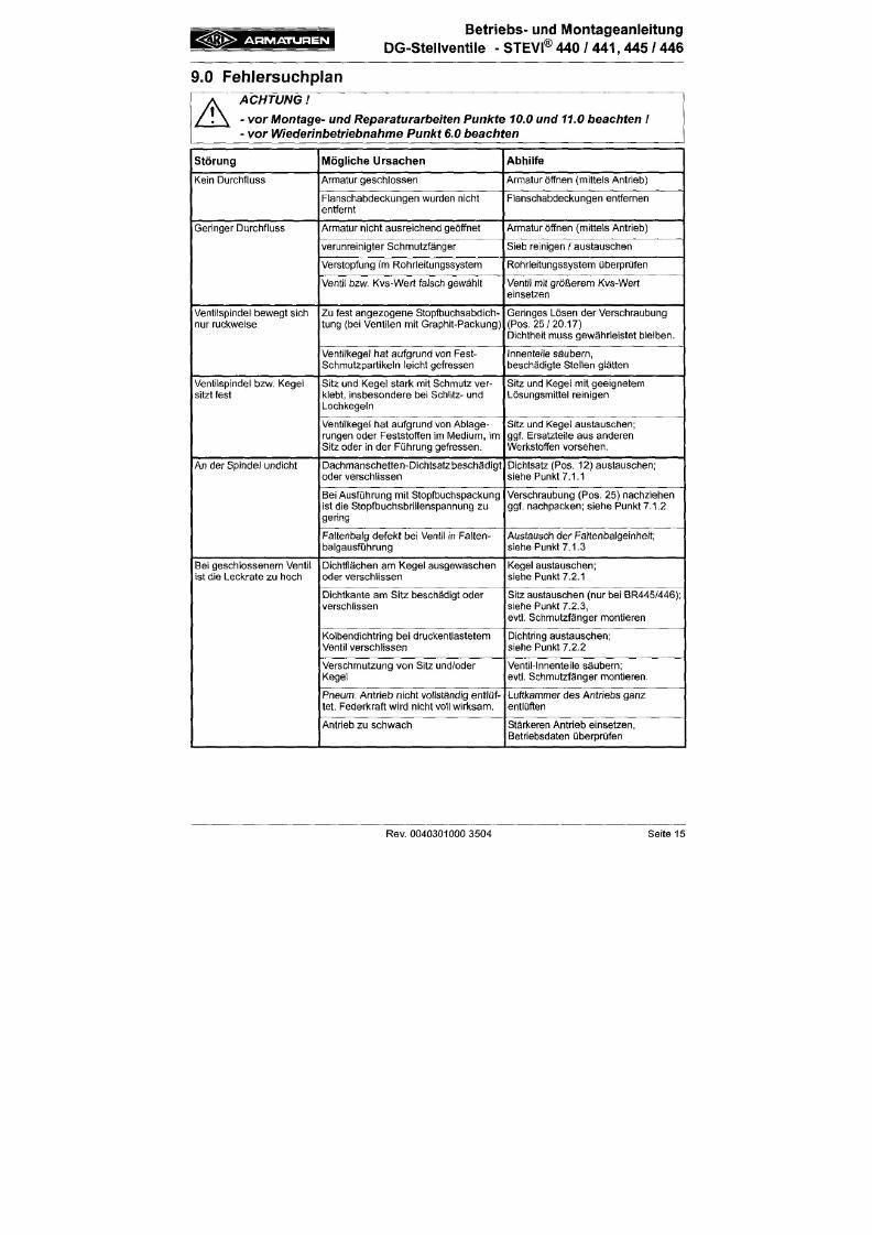
7/18/2019 M14 Thermal Fluid
http://slidepdf.com/reader/full/m14-thermal-fluid 140/486
A
Störung
Kein Durchfluss
Geringer Durchfluss
Ventilspindel bewegt sich
nur ruckweise
Ventilspindel bzw. Kegel
sitzt fest
Mö g l ich e Ursach en
Armatur geschlossen
Flanschabdeckungen wurden nicht
entfernt
Armatur nicht ausreichend geöffnet
verunreinigter Schmutzfänger
Verstopfung im Rohrleitungssystem
Ventil bzw. Kvs-Wert falsch gewählt
Zu fest angezogene Stopfbuchsabdich
tung (bei Ventilen mit Graphit-Packung)
Ventilkegel hat aufgrund von Fest-
Schmutzpartikeln leicht gefressen
Sitz und Kegel stark mit Schmutz ver
klebt, insbesondere bei Schlitz- und
Lochkegeln
Abhil fe
Armatur öffnen (mittels Antrieb)
Flanschabdeckungen entfernen
Armatur öffnen (mittels Antrieb)
Sieb reinigen / austauschen
Rohrleitungssystem überprüfen
Ventil mit größerem Kvs-Wert
einsetzen
Geringes Lösen der Verschraubung
(Pos.
25 /20 .17 )
Dichtheit muss gewährleistet bleiben.
Innenteile sä ubern ,
beschädigte Stellen glätten
Sitz und Kegel mit geeignetem
Lösungsmittel reinigen
A R M A T U R E N
Betriebs- und Montageanleitung
DG-Stellventile - STEVI® 440 /
441,
445 / 446
10.0 Dem ontage de r Arm atu r bzw. des Obe r te i les
ACHTUNG
Insbesondere sind folgende Punkte zu beachten:
7/18/2019 M14 Thermal Fluid
http://slidepdf.com/reader/full/m14-thermal-fluid 141/486
A
- Druckloses Rohrleitungssystem .
-
Abgekühltes
Medium.
-
Entleerte
A nlage.
- Bei ä tzenden, brennbaren,
aggressiven oder toxischen Medien
Rohrleitungs
system
belüften.
11.0 Garant ie / Ge w äh r le is tung
Umfang und Zeitraum der Gewährleistung ist in der
zum
Zeitpunl<t der Lieferung gültigen
Ausgabe der "Allgemeinen Geschäftsbedingungen der Albert Richter GmbH & Co. KG"
oder abweichend davon im Kaufvertrag selbst angegeben.
Wir leisten Gewähr für eine dem jeweiligen Stand der Technik und dem bestätigten Verwen
dungszweck entsprechenden Fehlerfreiheit.
Für Schäden, die durch unsachgemäße Behandlung oder Nichtbeachtung der Betriebs
und M ontageanleitung, des Katalogblattes und der einschlägigen Regelwerken entstehen,
können keine Gewährleistungsansprüche geltend gemacht werden.
Schäden die während des Betriebes, durch vom Datenblatt oder anderen Vereinbarungen
abweichenden Einsatzbedingungen entstehen, unterliegen ebenso nicht der Gewährleis
< Ä ß K > A R M A T U R E N
Betr iebs- und Montageanle i tung
DG -Ste liventile - STEVI®
440
/ 441,
445
/
446
1 2 . 0 K o n f o r m i t ä t s -
/
H ers t e l l e re rk lä rung
ARl-Armaturen Albert Richter Gm bH & Co. KG,
Mergelheide 5 6-60, 33756 Schloß Holte-Stukenbrock
7/18/2019 M14 Thermal Fluid
http://slidepdf.com/reader/full/m14-thermal-fluid 142/486
EG-Konformitätserklärung
im Sinne der
EG-Druckgeräterichtlinie97/23/EG
Hiermit erklären wir,
dass gemäß der oben genannten Druckgeräterichtlinie, die unten aufgelisteten Produkte ausgeführt
sind und nach D iagramm 6, Anhang II Modul H bzw. Modul H l (mit Sicherheitsfunktion; zusä tzlich
EG-Baumusterprüfung gemäß M odul B+D) von LLOY D'S REGISTER QUALITY ASSURANCE
(BS-Nr.
0525), Mönckebergstr. 2 7, 20095 Hamburg, geprüft wurden.
Modul H, Z ertifikat-Nr; 50003/1
Absperr- u. Stellventi l in Durchgangsform
Typ 405 , 460 , 440 , 441 , 445 , 446 , 470 , 471 , 422, 462, 425 , 426, 480
Angewendete Normen;
DIN EN 60534 Teil 1
VDIA/DE 3844 Blatt 1
DIN 3840
AD 2000 Merkblatt A4
- Gusseisen mit Kugelgraphit
- Stahlguss
- Schmiedestahl
A R M A T U R E N
Betriebs- und Montageanieitung
DG-Stellventiie - STEVI® 440 /
441,
445 / 446

7/18/2019 M14 Thermal Fluid
http://slidepdf.com/reader/full/m14-thermal-fluid 143/486
A R M A T U R E N
Operating and installation instructions
str a igh t throu gh co ntro l valves - STEVI® 440 /
441,
445 / 446
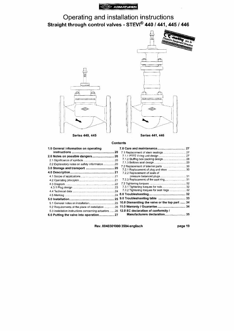
7/18/2019 M14 Thermal Fluid
http://slidepdf.com/reader/full/m14-thermal-fluid 144/486
S ? - ^ ^
"^^^^'o
A R M A T U R E N
Operating and installation instructions
Str. thr. control valves
- STEVI® 440
/ 441,445 /
446
1.0 Genera l in fo rmat ion on opera t ing ins t ruc t ions
These operating instructions provide information on mounting and maintaining the fittings.
Please contact the supplier or the manufacturer in case of problems which cannot be
solved by reference to the operating instructions.
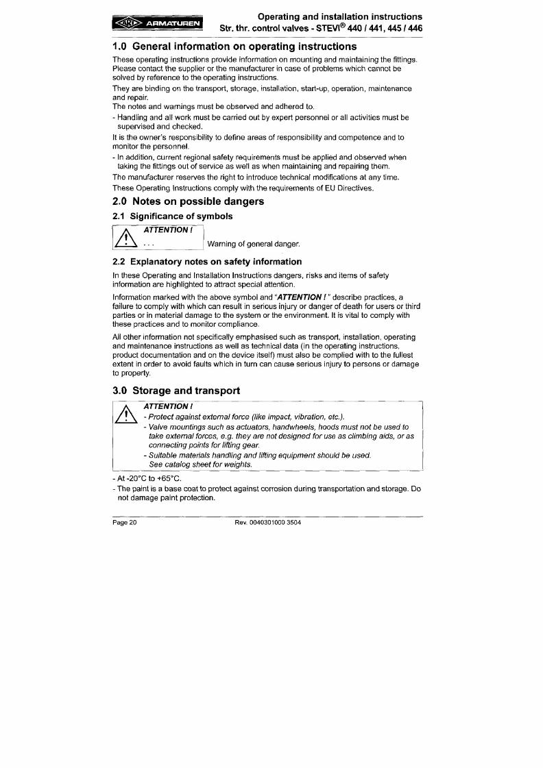
7/18/2019 M14 Thermal Fluid
http://slidepdf.com/reader/full/m14-thermal-fluid 145/486
They are binding on the transport, storage, installation, start-up, operation, maintenance
and repair.
The notes and warnings must be observed and adhered to.
- Handling and all work must be carried out by expert personnel or all activities must be
supervised and checked.
It is the owner's responsibility to define areas of responsibility and competence and to
monitor the personnel.
- In addition, current regional safety requirements must be applied and observed when
taking the fittings out of service as well as when maintaining and repairing them.
The m anufacturer reserves the right to introduce techn ical modifications at any time.
These Operating Instructions comply w ith the requirements of
EU
D irectives.
2.0 Notes on poss ib le dangers
2.1 Significance of symbols
A
ATTENTION
Warning of general danger.
i:aV'
A R M A T U R E N
Operating and installation instructions
Str. thr. control valves - STEVI®
440
/ 441,445 / 446
4 .0 Descr ip t ion
4.1 Scope of applications
Valves are used for „controlling the flow of liqu ids, gases and vapours in chemical and other
processing plants and for plant engineering".
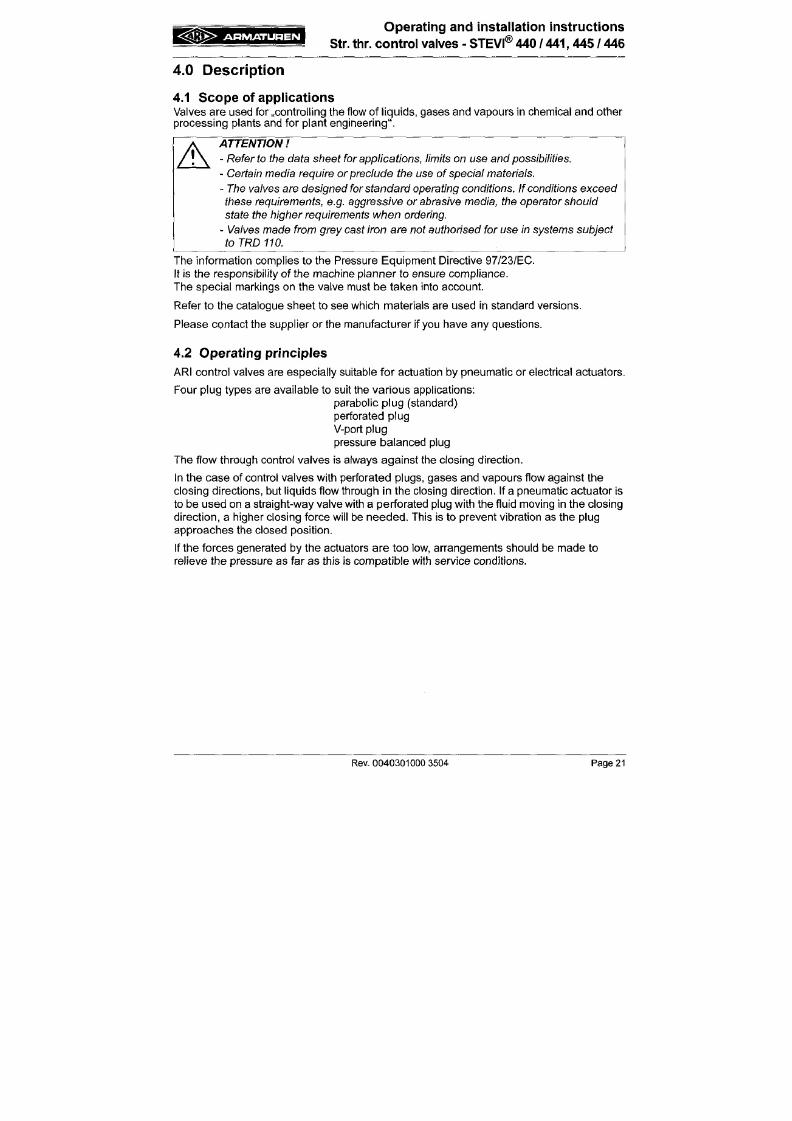
7/18/2019 M14 Thermal Fluid
http://slidepdf.com/reader/full/m14-thermal-fluid 146/486
A
ATTENTION
-
Refer to
the data sheet
for applications, limits
on use and
possibilities.
- Certain media require or preclude the use of special
materials.
-The
valves are designed for
standard
operating conditions.
If
conditions exceed
these requirements, e.g. aggressive
or
abrasive
media, the
operator should
state the higher requirements
when
ordering.
- Valves made from grey cast iron are no t authorised for use in systems subject
to
TRD 110.
The information complies to the Pressure Equipment Directive 97/23/EC.
It is the responsibility of the machine planner to ensure compliance.
The special markings on the valve must be taken into account.
Refer to the catalogue sheet to see which materials are used in standard versions.
Please contact the supplier or the manufacturer if
you
have any questions.
4.2 Operating principles
ARI control valves are especially suitable for actuation by pneumatic or electrical actuators.
A R M A T U R E N
Operat ing and insta l lat ion inst ruct ions
Str. thr . con trol va lves - STEVI® 440 / 441,445 / 446
4.3 Diagram
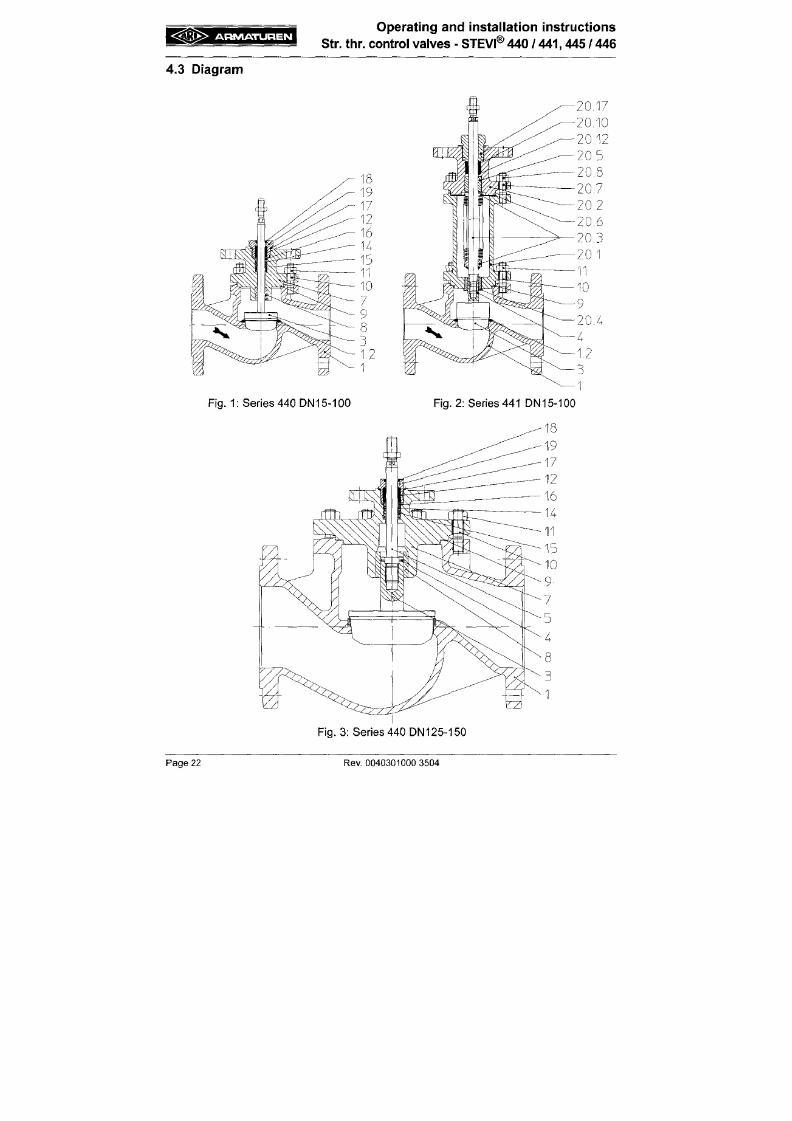
7/18/2019 M14 Thermal Fluid
http://slidepdf.com/reader/full/m14-thermal-fluid 147/486
A R M A T U R E N
Operat ing and insta l lat ion inst ruc t ions
Str. th r. contro l valves - STEVI® 440 / 441, 445 / 446
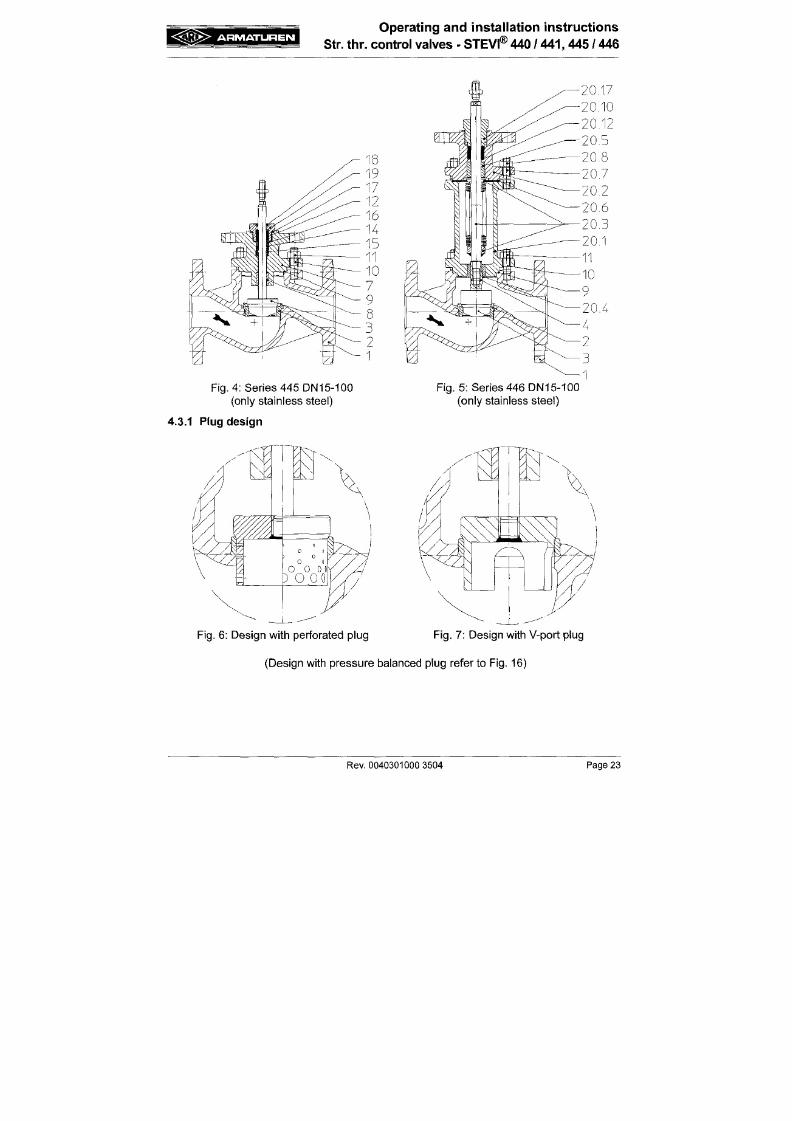
7/18/2019 M14 Thermal Fluid
http://slidepdf.com/reader/full/m14-thermal-fluid 148/486
A R M A T U R E N
Operat ing and insta l lat ion inst ruct ion s
Str. thr. co nt ro l valves - STEVI® 440 / 441,445 / 446
4.4 Technical data
for
- Principal dimensions
- Pressure-temperature-rat ings, etc. refer to data sheet.
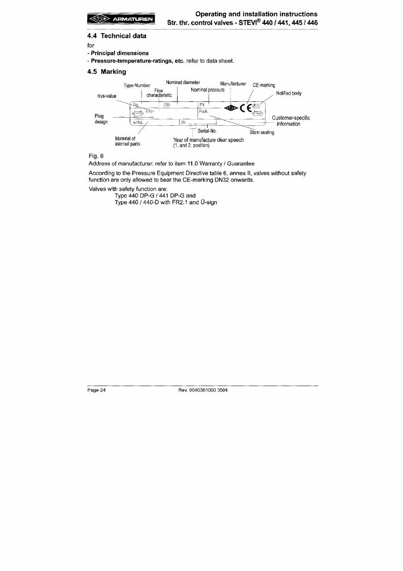
7/18/2019 M14 Thermal Fluid
http://slidepdf.com/reader/full/m14-thermal-fluid 149/486
4.5 Marking
Kvs-value
Plug
design
_ ., , Nominal diameter
Type-Number
Flow
characteristic
4E^
T K V ^
DN
Manufacturer
Nominal pressure
PN
Pack.
CE-marking
Notified body
^ >C €
<^
laMat.
SN
IVIaterial of
internal parts
Customer-specific
^ information
Serial-No,
Year of manufacture clear speech
( L a n d 2 .
position)
Stem sealing
Fig.
8
Address of manufacturer: refer to i tem 11.0 Warranty / Guarantee
Acc ording to the P ressure Equipmen t Direct ive table 6, an nex I I , valves without safety
funct ion are only al lowed to bear the CE-marking DN32 onwards.
Valves w ith safety funct ion a re:
A R M A T U R E N
Operating and installation instructions
Str. thr. control valves • STEVi® 440 / 441,445 / 446
5.0 Insta l la t ion
5.1 General notes on instal lat ion
The following items should be taken into account besides the general principles governing
installation work:
7/18/2019 M14 Thermal Fluid
http://slidepdf.com/reader/full/m14-thermal-fluid 150/486
A
ATTENTION
-
Remove flange covers
if
present.
-
Ttie
interior of
valve and
pipeline
must be
free from
foreign particles.
-
Note installation position
with
reference
to
flow,
see
mark on
valve.
- Steam line systems should be designed to prevent water accum ulation.
- Lay pipelines so that damaging
transverse,
bending and torsional forces are
avoided.
-
Protect valves from dirt
during
construction work.
-
Connection flanges must
mate
exactly.
- Valve mountings such as actuators, handwheels, hoods must not be used to
take external forces,
e.g. they
are
not
designed
fo r
use
as
climbing aids,
or
as
connecting points for lifting
gear
-
Suitable materials handling and lifting equipment should be
used.
Refer to data sheet fo r weights.
-
Keep
the
thread and
sha ft of
the stem
free
from paint.
- Centre gaskets between the
flanges.
A R M A T U R E N
Operat ing and insta l lat ion inst ruc t ions
Str. th r. con tro l valves - STEVI®
440
/ 441 ,445 / 446
5.2 Req uiremen ts at the place of instal lat ion
Th e place of instal lat ion should be easi ly accessible and provide am ple space for
maintenance and removing the actuator. Stop valves should be instal led before and after
the control valve to enable maintenance working without draining the piping system. The
va lve should preferably installed vert ical ly with the actuator at the top. Incl ined or horizontal
installation without supports is permissible only with l ight actuators.
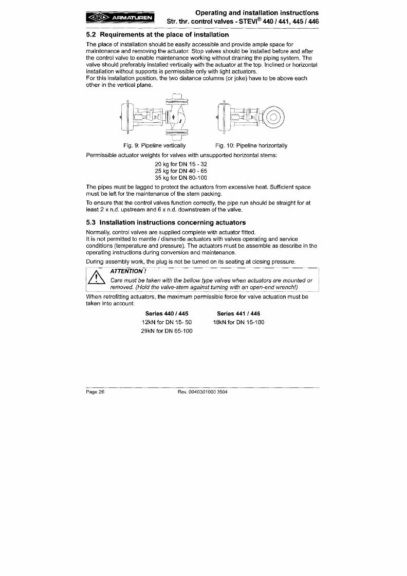
7/18/2019 M14 Thermal Fluid
http://slidepdf.com/reader/full/m14-thermal-fluid 151/486
For this installation posi t ion , the two distan ce column s (or jok e) have to be above eac h
other in the vertical plane.
Fig.
9: Pipe line vertically Fig. 10: Pipeline horizontally
Permissible actuator weights for valves with unsupported horizontal stems:
20 kg for DN 1 5 - 3 2
25 kg for DN 40 - 65
35 kg for DN 80-100
Th e pipes must be lagge d to protect the actuators from exce ssive heat. Suff ic ient sp ace
mu st b e left for the ma intenanc e of the ste m pa cking.
A R M A T U R E N
Operating and installation instructions
Str. thr. control valves • STEVI® 440 / 441,445 / 446
6.0 Pu t t ing th e valve into op era t ion
ATTENTION
- Before putting the valve into operation, check material, pressure, temperature
and
direction
of
flow.
- Regional safety instructions must be adhered to.
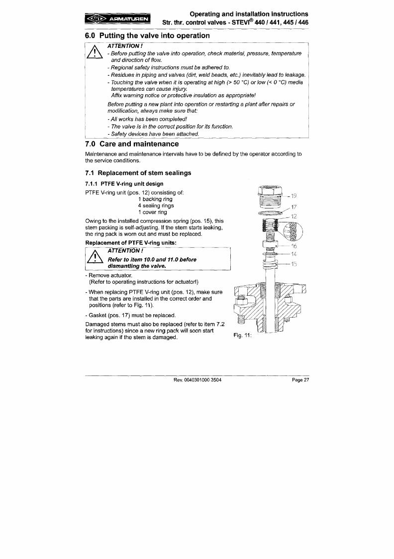
7/18/2019 M14 Thermal Fluid
http://slidepdf.com/reader/full/m14-thermal-fluid 152/486
A
- Residues in piping and valves (dirt, weld beads, etc.) inevitably lead to leakage.
-
Touching
the
valve when
it is
operating
at
high
(> 50
°C)
or
low (<
0
°C)
m edia
temperatures can cause injury.
Affix
warning notice
or
protective insulation
as appropriate
Before
putting a
new
plant
into operation
or
restarting
a plant
after repairs
or
modification,
always make
sure
that:
- Al l
works
has
been completed
-
The
valve is in the
correct position
fo r
its
function.
- Safety devices have been attached.
7.0 Care an d ma inten an ce
Maintenance and maintenance intervals have to be defined by the operator according to
the service conditions.
7.1 Replacement of stem sealings
7.1.1 PTFE V-ring unit design
g 3fe>
A R M A T U R E N
Operat ing and insta l lation inst ruc t ions
Str. thr. co ntro l valves - STEVI® 440 / 441,445 / 446
7.1.2 Stuffing box packing design
- The stuffing box packing (pos. 23) requires maintenance.
- If leaks develop, immediately tighten the screw joint (pos. 25) gradually until the packing
(pos.
23) stops leaking.
- The service life of stuffing box packings (pos. 23) can be increased by checking regularly
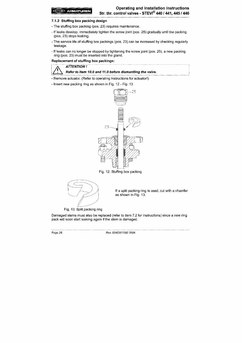
7/18/2019 M14 Thermal Fluid
http://slidepdf.com/reader/full/m14-thermal-fluid 153/486
leakage.
- If leaks can no longer be stopped by tightening the screw join t (pos. 25), a new packing
ring (pos. 23) must be inserted into the gland.
Replacement of stuffing box packings:
A
ATTENTION
Refer to
item
10.0
and
11.0 before dismantling
th e valve.
• Remove actuator. (Refer to operating instructions for actuator )
•
Insert new packing ring as shown in Fig. 12 - Fig. 13.
A R M A T U R E N
Operating and Installation instructions
Str. thr. control valves • STEVI® 440 / 441 ,445 / 446
7.1.3 Bellows seal design
I f the stem leaks, the bel lows seal (p os . 20.3) is defect ive. Th e leak can in i t ia l ly be stopped
by t ightening the sc rew joint (pos. 20.1 7).
Stem and bel lows (pos. 20.3) can only be replaced together.
Replacem ent of bel lows seals:
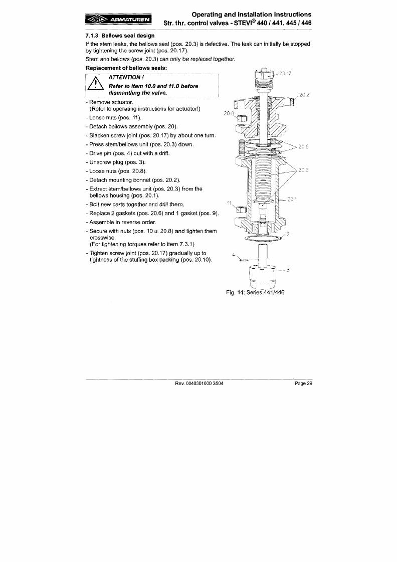
7/18/2019 M14 Thermal Fluid
http://slidepdf.com/reader/full/m14-thermal-fluid 154/486
A
ATTENTION
Refer to item 10.0 and 11.0 before
dismantling the valve.
20,17
- Remove actuator.
(Refer to operating instructions for actuator )
- Loose nuts (pos. 11).
- Detach bel lows assembly (pos. 20).
- Slacken screw joint (pos. 20.17) by about one turn.
- Press stem/bel lows uni t (pos. 20.3) down.
- D rive pin (pos . 4) out with a drift.
- Unscrew plug (pos. 3).
- Loose nuts (pos. 20.8).
- Detach mount ing bonnet (pes. 20.2).
- Extract stem/bel lows uni t (pos. 20 .3) f rom the
20,8
20,2
20,6
20,3
A R M A T U R E N
Operat ing and insta l lat ion inst ruc t ions
Str. thr. co nt ro l valves - STEVI® 440 / 441, 445 / 446
7.2 Replacem ent of intern al parts
7.2.1 Replacem ent of plug and stem
ATTENTION
Refer to item 10.0 and 11.0 before
dismantling the valve.
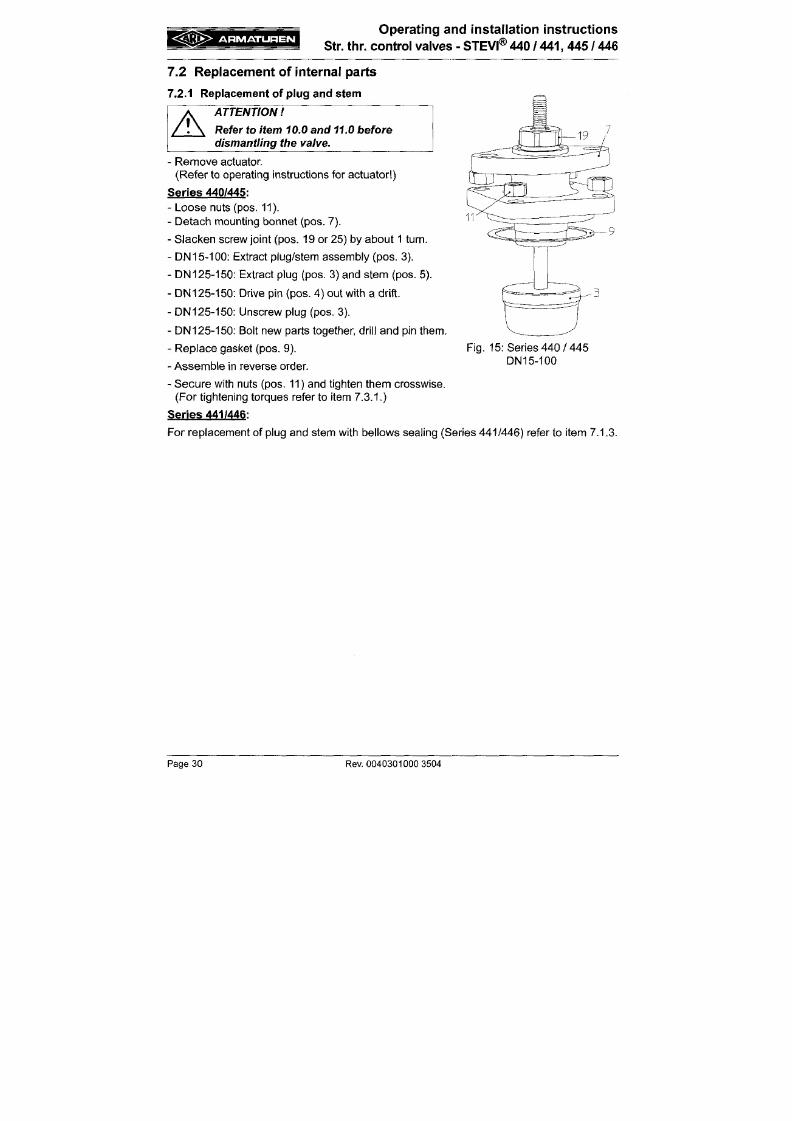
7/18/2019 M14 Thermal Fluid
http://slidepdf.com/reader/full/m14-thermal-fluid 155/486
A
-
Remove actuator.
(Re fer to operat ing instruct ions for actua tor )
Series 440/445:
- Loose nuts (pos. 11).
- Detach mount ing bonnet (pos. 7),
- Slac ken screw joint (pos. 19 or 25) by about 1 turn.
- D N 15-100: Extract plug/stem assem bly (pos. 3).
- D N 125-150 : Extract plug (pos. 3) and stem (pos. 5).
- D N1 25- 150 : Drive pin (pos. 4) out wi th a d r i ft .
- DN125-150: Unscrew plug (pos. 3).
- DN125-150: Bolt new parts together, dri l l and pin them.
- Replace gasket (pos. 9).
- Assemble in reverse order.
Fig. 15: Series 440 / 445
DN15-100
g J i ^
A R M A T U R E N
Operating and installation instructions
Str. tlir. control valves - STEVI® 440 / 441 ,445 / 446
7.2.2 Rep lacem ent of seals of pre ssu re balanced plu gs
A
ATTENTION
Refer to item 10.0 and 11.0 before dismantling tfie valve.
-
Remove actuator.
(Refer to operating instructions for actuator )
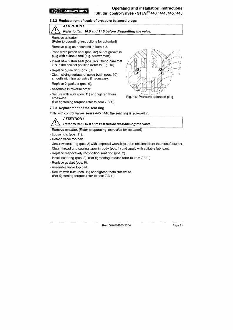
7/18/2019 M14 Thermal Fluid
http://slidepdf.com/reader/full/m14-thermal-fluid 156/486
- Remove plug as described in i tem 7.2.
- Prise worn piston seal (pos. 32) out of groove in
plug with su i table tool (e.g. screwd river).
- Insert new piston seal (pos. 32), taking care that
it is in the corre ct position (refer to F ig. 16 ).
- Replace guide ring (pos. 31).
- Clean sl iding surfac e of guide bush (p os. 30);
smoo th with f ine abrasive if necessary.
- Replace 2 ga skets (pos. 9).
- Assemble in reverse order.
- Secure with nuts (po s. 11) and t ighten them
crosswise.
(For tightening torques refer to item 7.3.1.)
7.2.3 Rep lacem ent of the seat ring
Fig .
16: Pressure balanced
A R M A T U R E N
Operating and installation instructions
Str. thr. control valves
- STEVI® 440
/ 441,445 / 446
7.3 Tightening torques
7.3.1 Tightening torques for
M 1 0 = 1 5 - 3 0 N m
M 1 2 = 3 5 - 5 0 Nm
M 16 = 80 -12 0Nm
7/18/2019 M14 Thermal Fluid
http://slidepdf.com/reader/full/m14-thermal-fluid 157/486
7.3.2 Tightening torques for seat rings
DN 15/20
DN 25/ 32
DN
40 / 50
DN65
DN80
DN100
=
=
=
=
=
=
100 Nm
150 Nm
350 Nm
480 Nm
660 Nm
980 Nm
/ Refer to operating instructions for actuator concerned for
installing actuators I
8 .0 Troub leshoo t ing
In the event of m alfunction or faulty operating performance checl< that the installation and
A R M A T U R E N
Operating and installation instructions
Str. thr. control valves - STEVI® 440 / 441,445 / 446
9 .0 T roub leshoot ing t ab le
ATTENTION
- read item 10.0 and 11.0 prior to dismantling and repair
work
- read
item
6.0
before
restarting
the
plant
7/18/2019 M14 Thermal Fluid
http://slidepdf.com/reader/full/m14-thermal-fluid 158/486
A
Fault
No flow
Little flow
Valve stem moves in jerks.
Valve stem or plug cannot be
moved.
P os s ib le c a us e
Valve close d.
Flange covers not removed.
Valve not sufficiently open.
Dirt sieve clogg ed.
Piping system clogged.
Kvs value of valve unsuitable.
Stuffing box sealing too tight
(for valves with graphite packings).
Valve plug slightly seized owing to
solid dirt particles.
Seating and plug clogged with dirt;
especially with V-port and perforated
plugs.
Valve plug seized in seating or guide
owing to d eposits or dirt in medium .
Correct ive measures
Open valve (using actuator).
Remove flange cov ers.
Open valve (using actuator).
Clean / replace sieve.
Check piping system .
Fit valve with higher Kvs value.
Slacken screw joint (pos. 25/20.17)
slightly Valve must nor start leaking
Clean internals, smooth rough spots.
Clean seating and plug with suitable
solvent.
Replace plug and seating; use parts
made from different material if neces
sary.
A R M A T U R E N
Operating and installation instructions
Str. thr. control valves
- STEVI® 440
/ 441,445 /
446
10.0 Dismant l ing the valve or the top part
A
ATTENTION
The following points
must
be
observed:
-
Pressureless
pipe sys tem.
- Medium must be
cool.
7/18/2019 M14 Thermal Fluid
http://slidepdf.com/reader/full/m14-thermal-fluid 159/486
-
Plant must be drained.
- Purge piping systems in case o f caustic, inflammable, aggressive or toxic
media.
11.0 Warranty / Guarantee
The extent and period of warranty cover are specified in the "Standard Terms and
Conditions of Albert Richter GmbH & Co. KG" va lid at the time o f delivery or, by way of
departure, in the contract of sale itself.
We guarantee freedom of faults In compliance w ith state-of-the-art technology and the
confirmed application.
No warranty claims can be made for any damage caused as the result of incorrect handling
or disregard of operating and installation Instructions, datasheets and relavant regulations.
This warranty also does not cover any damage which occurs during operation under
conditions deviating from those laid down by specifications or other agreements.
Justified complaints will be eliminated by repair carried out by us or by a specialist
A R M A T U R E N
Operating and installation instructions
Str. thr. control valves - STEVI®
440
/ 441,445 / 446
12 .0 EC dec la ra t ion o f conformi ty / Manufac turers dec la ra t ion
ARI-Armaturen Albert Richter Gm bH & C o. KG,
Mergelheide 56-60, D-33756 Schloß Holte-Stukenbrock
EC declaration of conformity
as defined by
7/18/2019 M14 Thermal Fluid
http://slidepdf.com/reader/full/m14-thermal-fluid 160/486
the Pressure Equipment Directive 97/23/EC
Herewith we declare,
that according to the above m entioned Pressure Equipmen t Directive (PE D) the below listed
prod
ucts comp ly an d have been app roved according to table 6, annex II module H or module H1 (w ith
safety function: also EC type test according to module B+D) through LLOYD'S REGISTER QUAL
ITY ASSU RANC E (NB-No. 0525), M önckebergstr, 27 , D-20095 Hamburg.
Module H, Certificate-No: 50003/1
Straight through stop and control valves
Type 405 , 460, 440, 4 41 , 445 , 446, 470, 4 71 , 422, 462, 425 , 426, 480
Applied stan dard:
DIN EN 6 0534 part 1
VDIA/DE 384 4 sheet 1
DIN 3840
AD 2000 leaflet A4
- C ast iron with spheroidal graphite
- Cast steel
- Forged steel
ARMATUREN
Operating and installation instructions
Str. thr. control valves
-
STEVI®
440
/ 441,445 / 446

7/18/2019 M14 Thermal Fluid
http://slidepdf.com/reader/full/m14-thermal-fluid 161/486
A R M A T U R E N
Betriebs- und Montageanleitung
3-W ege-Stellventile - STEVI® 450 / 451
7/18/2019 M14 Thermal Fluid
http://slidepdf.com/reader/full/m14-thermal-fluid 162/486
^M
d ia
A R M A T U R E N
Betriebs- und M ontageanleitung
3-Wege-Steilventiie
- STEVI®
450
/ 451
1.0 A l lge m eine s zur B et r iebsa n le i tun g
Diese Betriebsanleitung gilt als Anweisung, die Armaturen sicher zu montieren und zu
warten.
Bei Schwierigkeiten, die nicht mit Hilfe der Betriebsanleitung gelöst werden
können, nehm en Sie Kontakt mit dem Lieferant oder Hersteller auf.
Sie ist verbindlich für den Transport, Lagerung, M ontage, Inbetriebnahme, Betrieb,
Wartung,
Reparatur.
7/18/2019 M14 Thermal Fluid
http://slidepdf.com/reader/full/m14-thermal-fluid 163/486
Die Hinweise und Warnungen sind zu beachten und einzuhalten.
- Handling und alle anderen Arbeiten sind von sachkundigem Personal durchzuführen bzw.
alle Tä tigkeiten sind zu beaufsichtigen und zu prüfen.
Die Festlegung des Verantwortungsbereiches, des Zuständigkeitsbereiches und der
Übenwachung des Personals obliegt dem Betreiber.
- Bei Außerbetriebsetzung, Wartung bzw. Reparatur sind zusätzlich die aktuellen
regionalen Sicherheitsanforderungen heranzuziehen und zu beachten.
Der Hersteller behält sich das Recht von technischen Änderungen und Verbesserungen
jederzeit vor.
Diese Betriebsanleitung entspricht den Anforderungen der EU-Richtlinien.
2.0 Gefahrenh inweise
2.1 Bedeutung der Symboie
A
ACHTUNG
Warnung vor einer allgemeinen Gefahr.
= ^ 3 T K > ARMATUREN
Betriebs- und Montageanleitung
3-Wege-Stellventile - STEVI® 45 0 / 45 1
4 .0 Be s c h r e ib u n g
4.1 Anwendungsbereich
Armaturen werden zum „Regeln von flüssigen, gasförmigen und dampfförmigen M edien in
der Verfahrens- und Prozesstechnik sowie im Anlagenbau" eingesetzt.
7/18/2019 M14 Thermal Fluid
http://slidepdf.com/reader/full/m14-thermal-fluid 164/486
A
ACHTUNG
- Einsatzgebiete, Einsatzgrenzen und -möglichil<eiten sind dem Katalogblatt zu
entnehmen.
- Bestimmte Medien setzen spezielle Werkstoffe voraus oder sctiließen sie aus.
- Die Armaturen sind ausgelegt fü r normale Einsatzbedingungen. Gehen die
Bedingungen über diese Anforderungen
hinaus,
wie
z.B.
aggressive
oder abra
sive Med ien, hat der Betreiber die höheren Anforderungen bei der Bestellung
anzugeben.
- Armaturen aus Grauguss sind fü r den Einsatz in Anlagen nach TRD 110 nicht
freigegeben.
Die Angaben sind konform mit der Druckgeräterichtlinie 97/23/EG.
Die Einhaltung unterliegt der Verantwortung des Anlagenplaners.
Besondere Kennzeichnungen der Armatur s ind zu beachten.
Die Werkstoffe der Standard-Ausführungen sind dem Katalogblatt zu entnehmen.
Bei Fragen ist Rücksprache mit dem Lieferanten oder Hersteller zu führen.
A R M A T U R E N
Betriebs- und iVIontageanleitung
3-Wege-Stellventile
- STEVI® 450 / 451
4.3 Schaubilder
4.3.1 Ausführung mit Mischkegel
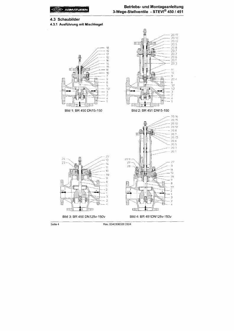
7/18/2019 M14 Thermal Fluid
http://slidepdf.com/reader/full/m14-thermal-fluid 165/486
Bild
1:BR450DN15-150
Bild 2 : ER
451
DN15-150
A R M A T U R E N
Betriebs- und Montageanleitung
3-Wege-Stellventiie
- STEVI® 450 / 451
4.3.2 Ausführung mit Verteill^egei
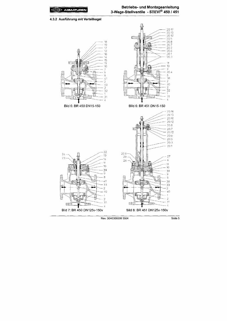
7/18/2019 M14 Thermal Fluid
http://slidepdf.com/reader/full/m14-thermal-fluid 166/486
Bild 5: BR 450 DN15-150 Bild 6: BR
451
DN15-150
A R M A T U R E N
Betr iebs- und Montageanlei tung
3-W ege -Stel iventi le - STEVf® 450 / 451
4.4 Techiniscl ie Daten
wie z.B.
-
Hauptabmessungen,
- Druck-Temperatur-Zuordnungen, usw.
s ind dem Katalogblatt zu entnehm en.
4.5 Kennzeichinung
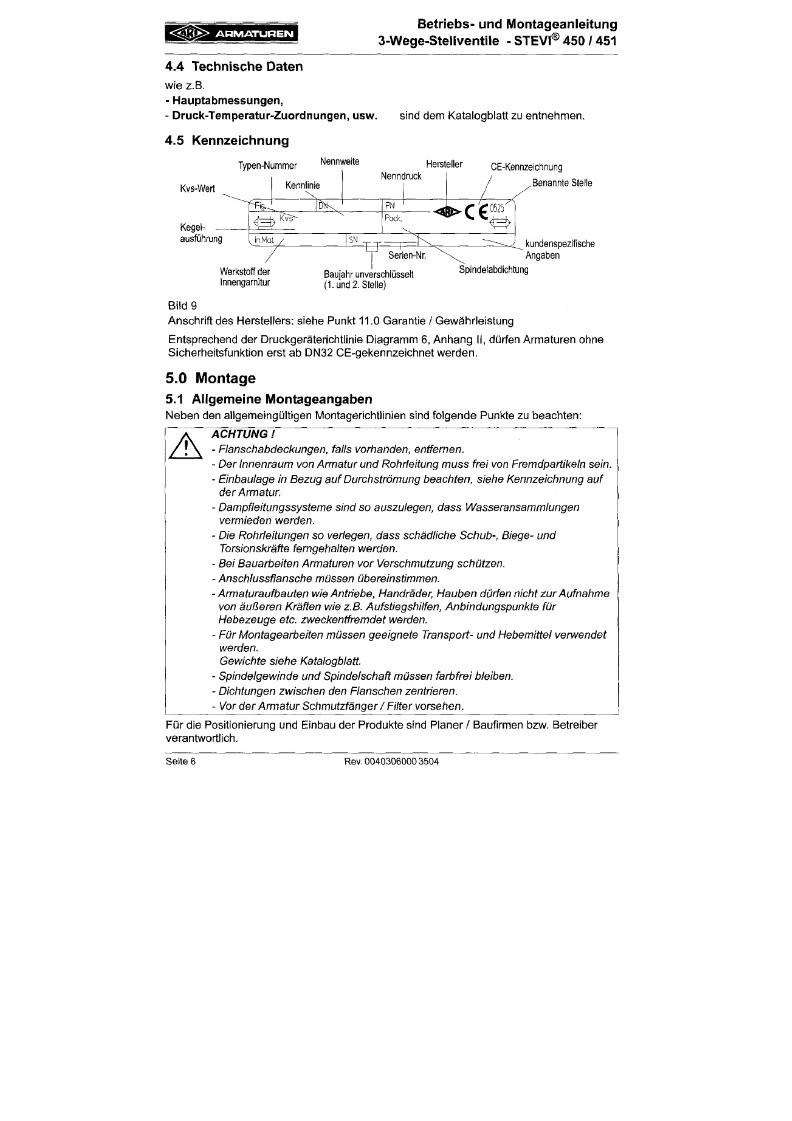
7/18/2019 M14 Thermal Fluid
http://slidepdf.com/reader/full/m14-thermal-fluid 167/486
Kvs-Wert
Kegei-
ausführung
Typen-Nummer
Kennlinie
Nennweite
Hersteller
Nenndrucl<
CE-Kennzeichnung
, Benannte Stelle
kundenspezifsche
Angaben
Werkstoff der
Innengarnitur
Baujahr unverschlüsselt
( lu n d 2. Stelle)
Spindelabdichtung
Bild 9
Anschri f t des Herstel lers: s iehe Punkt 11.0 Garantie / Gewährleistung
Entsprech end der Druckgerätericht l lnle Diagram m 6, An ha ng II , dürfen Arm aturen ohne
Sicherheitsfunkt ion erst ab DN32 CE-gekennzelchnet werden.
5 . 0 M o n t a g e
« Ä M K >
ARMATUREN
Betr iebs- und Montageanlei tung
3-Wege-Stellventile
- STEVI® 450 / 451
5.2 IVIontageangaben zum Einbauort
Die Einbaustelle soll gut zugänglich sein und genügend Freiraum zur Wartung und zum
Abnehmen der Stellantriebe aufweisen. Vor und hinter dem Stellventil sind
Handabsperrventile vorzusehen, die Wartungs- und Reparaturarbeiten am Stellventil
ermöglichen, ohne die Anlage zu entleeren. Das Stellventil soll vorzugsweise senkrecht mit
obenliegendem Antrieb eingebaut
werden.
Schräge bis waagerechte Einbaulage ist ohne
AbStützung nur bei Antrieben mit geringem Eigengewicht zulässig.
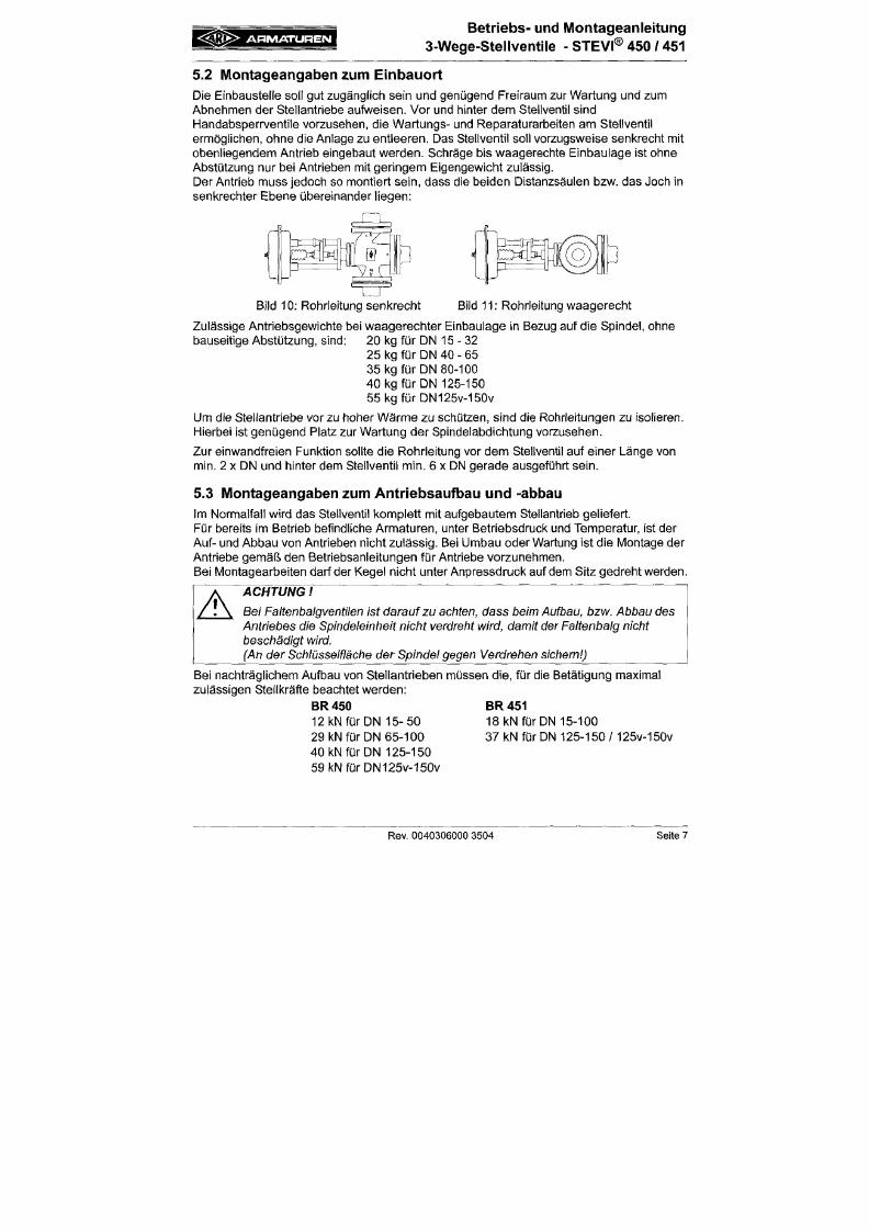
7/18/2019 M14 Thermal Fluid
http://slidepdf.com/reader/full/m14-thermal-fluid 168/486
Der Antrieb muss jedoch so montiert sein, dass die beiden Distanzsäulen bzw. das Joch in
senkrechter Ebene übereinander liegen:
Bild 10; Rohrleitung senkrecht
Bild
11:
Rohrleitung waagerecht
Zulässige Antriebsgewichte bei waagerechter Einbaulage in Bezug auf die Spindel, ohne
bauseitige Abstützung, sind: 20 kg für DN 15 -3 2
25 kg für
DN
40 - 65
35 kg für DN 80-100
40 kg für DN 125-150
55kgfürDN125v-150v
Um die Stellantriebe vor zu hoher Wärm e zu schützen, sind die Rohrleitungen zu isolieren.
A R M A T U R E N
Betriebs- und Montageanleitung
3-Wege-Steliventile - STEVI® 45 0 / 45 1
6 .0 Inbe t r i ebnahme
A
ACHTUNG
- Vor der Inbetriebnahme sind die Angaben zu Werkstoff,
Druck,
Temperatur und
Strömungsrichtung
zu überprüfen.
- Grundsätzlich sind die regionalen Sicherheitsanweisungen einzuhalten.
-
Rückstände
in
Rohrleitungen
und
Armaturen
(wie
Schmutz,
Schweißperlen,
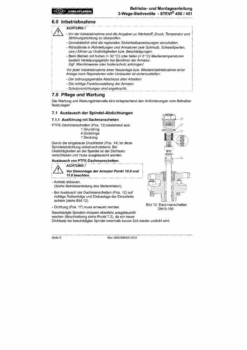
7/18/2019 M14 Thermal Fluid
http://slidepdf.com/reader/full/m14-thermal-fluid 169/486
usw.) führen zu Undichtigkeiten bzw.
Beschädigungen.
-
Beim Betrieb
mit
hohen
(> 50 °C) oder
tiefen
(<0°C)
Medientemperaturen
besteht
Verletzungsgefahr bei
Berühren
der A rmatur
Ggf
Warnhinweise
oder
Isoiierschutz
anbringen
Vor eder
Inbetriebnahme einer Neuanlage bzw. Wiederinbetriebnahme
einer
Anlage nach Reparaturen oder Umbauten ist sicherzustellen:
- Der ordnungsgemäße Abschluss aller A rbeiten
-
Die richtige Funktionssteliung
der A rmatur
-
Schutzvorrichtungen
sind angebracht.
7 .0 P f l ege und W ar t u ng
Die Wartung und Wartungsintervalle sind entsprechend den Anforderungen vom Betreiber
festzulegen
7.1 Austausch der Spindel-Abdichitungen
A R M A T U R E N
Betriebs- und Montageanleitung
3-Wege-Stellventile - STEVI® 45 0 / 45 1
7.1.2 Ausführung mit Stopfbuchspackung
Die Stopfbuchspackung (Pos. 13) ist nicht wartungsfrei.
Bei auftretenden Undichtigkeiten sofort die Verschraubung (Pos. 42) bzw. stufenweise die
Sechskantmuttern (Pos. 24) gleichmäßig, bis zur Dichtheit der Packung (Pos. 13)
anziehen.
Durch regelmäßige Kontrolle auf Dichtheit wird die Lebensdauer der Stopfbuchspackung
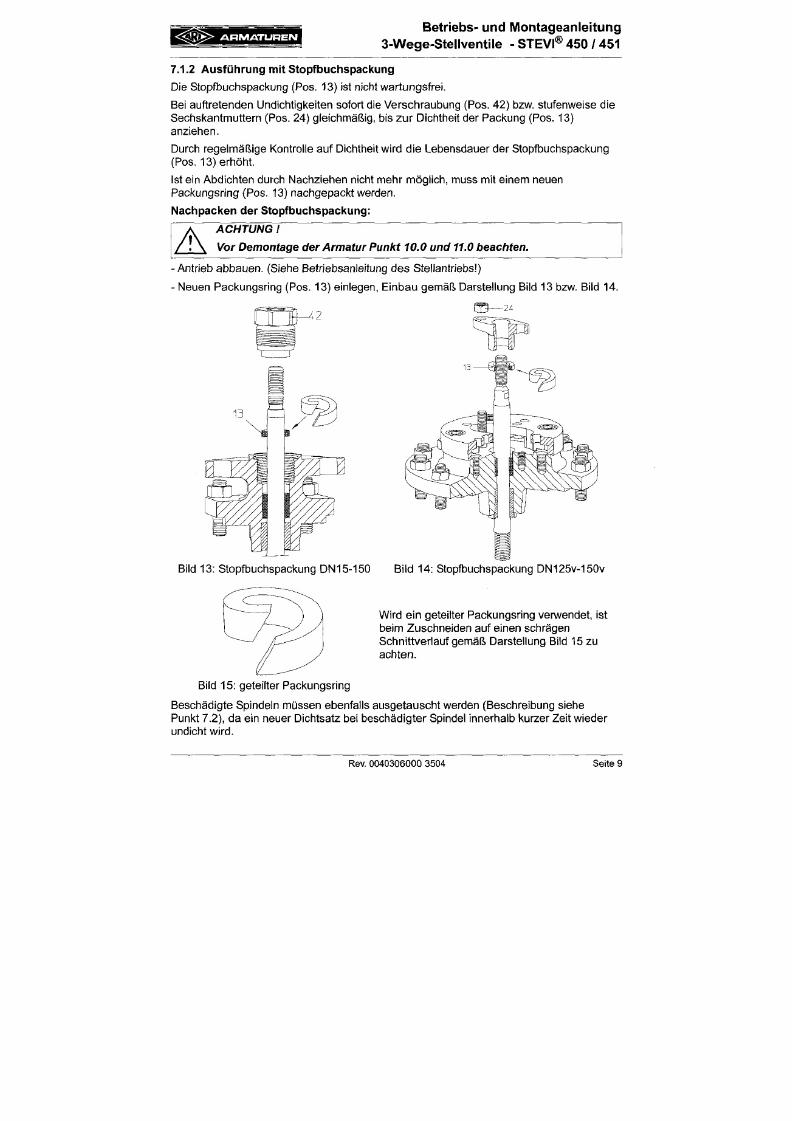
7/18/2019 M14 Thermal Fluid
http://slidepdf.com/reader/full/m14-thermal-fluid 170/486
(Pos. 13) erhöht.
Ist ein Abdichten durch Nachziehen nicht mehr möglich, muss mit einem neuen
Packungsring (Pos. 13) nachgepackt werden.
Nachpacken der Stopfbuchspackung:
A
ACHTUNG
Vor
Demontage der Armatur Punkt
10.0 und
11.0
beachten.
•
Antrieb abbauen. (Siehe Betriebsanleitung des Stellantriebs )
• Neuen Packungsring (Pos. 13) einlegen, Einbau gemäß Darstellung Bild 13 bzw. Bild 14.
A R M A T U R E N
Betr iebs- und Montageanlei tung
3-Wege-Stellventile
- STEVI® 450 / 451
7.1.3 Ausführung mit Faltenbalg
Bei Undichtigkeiten an der Spindel liegt ein Defekt des eingebauten Faltenbalges
(Pos. 20.3) vo r Zunächst kann durch leichtes Anziehen der Verschraubung (Pos. 20.17)
bzw. der Überwurfmutter (Pos. 20.16) eine ausreichende Dichtheit erz ielt werden.
Bei einem Austausch können Spindel und Faltenbalg (Pos. 20.3) nur gemeinsam
ausgetauscht werden.
Austausch der Faltenbalgeinheit:
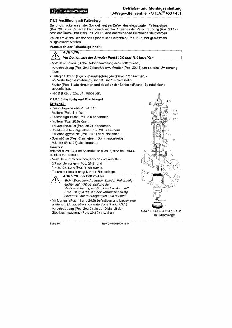
7/18/2019 M14 Thermal Fluid
http://slidepdf.com/reader/full/m14-thermal-fluid 171/486
A
ACHTUNG
Vor Demontage
der Armatur Punkt
10.0
und
11.0
beachten.
-
Antrieb abbauen. (Siehe Betriebsanleitung des Stellantriebs )
- Verschraubung (Pos. 20.17) bzw.Übenwurfmutter (Pos. 20.16) um ca . eine Umdrehung
lösen.
- Unteren Sitzring (Pos. 2) herausschrauben (Punkt 7.2 beachten) -
bei Verteilkegelausführung (Bild 18, Bild 19) nicht nötig.
- Mutter (Pos. 4) abschrauben und dabei an der Schlüsselfläche (Spindel oben)
gegenhalten.
- Kegel (Pos. 3 bzw. 31) ausbauen .
7.1.3.1 Faltenbalg und Mischkegel
P NI 5-150
- Demontage gemäß Punkt 7.1.3.
A R M A T U R E N
Betriebs- und Montageanleitung
3-Wege-Stellventile - STEVI® 45 0 / 45 1
DN125V-150V
- Demontage gemäß Punkt 7.1.3.
- Muttern (Pos. 29) lösen.
- Fal tenbalgaufsatz (Pos. 20) abnehmen.
- M ut tem (Pos. 20.8) lösen.
20 16
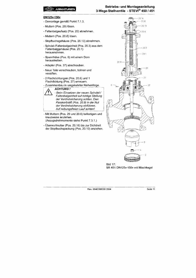
7/18/2019 M14 Thermal Fluid
http://slidepdf.com/reader/full/m14-thermal-fluid 172/486
- Stopfbuchsgehäuse (Pos . 20.13) abneh m en.
- Spindel-ZFaltenbalgeinheit (Pos. 20.3) aus dem
Faltenbalggehäuse (Pos. 20.1)
herausnehmen.
- Spannhülse (P os. 6) mit e inem Dorn
heraustreiben.
- Adapter (Pos. 37) abschrauben.
- Neue Tei le verschrauben, bohren und
verstiften.
- 2 Flachdichtungen (Pos. 20.6) und 1
Flachdichtung (Pos. 27) erneuern.
- Zusammenbau in umgekehr ter Reihenfo lge.
ACHTUNG
-
Beim Einsetzen der neuen Spindei-/
A R M A T U R E N
Betriebs- und Montageanleitung
3-Wege-Stellventile - STEVI® 45 0 / 45 1
7.1.3.2 Faltenbalg und Verteilkegel
DN40-150
- Demontage gemäß Punkt 7.1.3.
- Distanzhülse (Pos. 32) von dem Adapter (Pos. 38)
ziehen.
Hinweis:
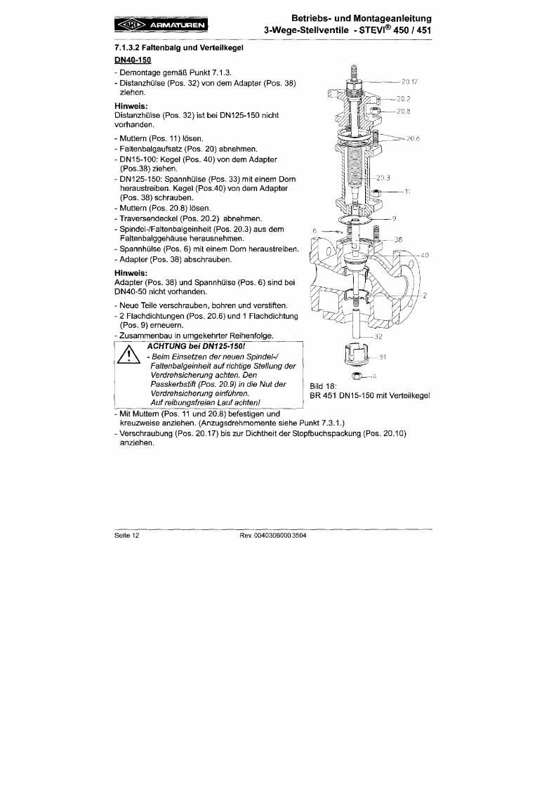
7/18/2019 M14 Thermal Fluid
http://slidepdf.com/reader/full/m14-thermal-fluid 173/486
Distanzhülse (Pos. 32) ist bei DN125-150 nicht
vorhanden.
- IVluttern (Pos. 11) lösen.
- Faltenbalgaufsatz (Pos. 20) abnehmen.
- DN15-100: Kegel (Pos. 40) von dem Adapter
(Pos.38) ziehen.
- DN125-150: Spannhülse (Pos. 33) mit einem Dorn
heraustreiben. Kegel (Pos.40) von dem Adapter
(Pos.
38) schrauben.
- IVluttern (Pos. 20.8) lösen.
- Traversendeckel (Pos. 20.2) abnehmen.
- Spindel-ZFaltenbalgeinheit (Pos. 20.3) aus dem
Faltenbalggehäuse herausnehmen.
- Spannhülse (Pos. 6) mit einem Dorn heraustreiben.
- Adapter (Pos. 38) abschrauben.
A R M A T U R E N
Betr iebs- und Montageanlei tung
3-W ege-Stellventile - STEVI® 450 / 45 1
DN125V-150V
- De mo ntage gem äß Punl<t 7.1.3.
- Muttern (Pos. 11) lösen.
- Fal tenbalgaufsatz (Pos. 20)
incl.
Stopfbuchsgehäuse (Pos. 39) abnehmen.
- Spannhülse (Pos. 33) mit e inem Dorn
20,16
20,8
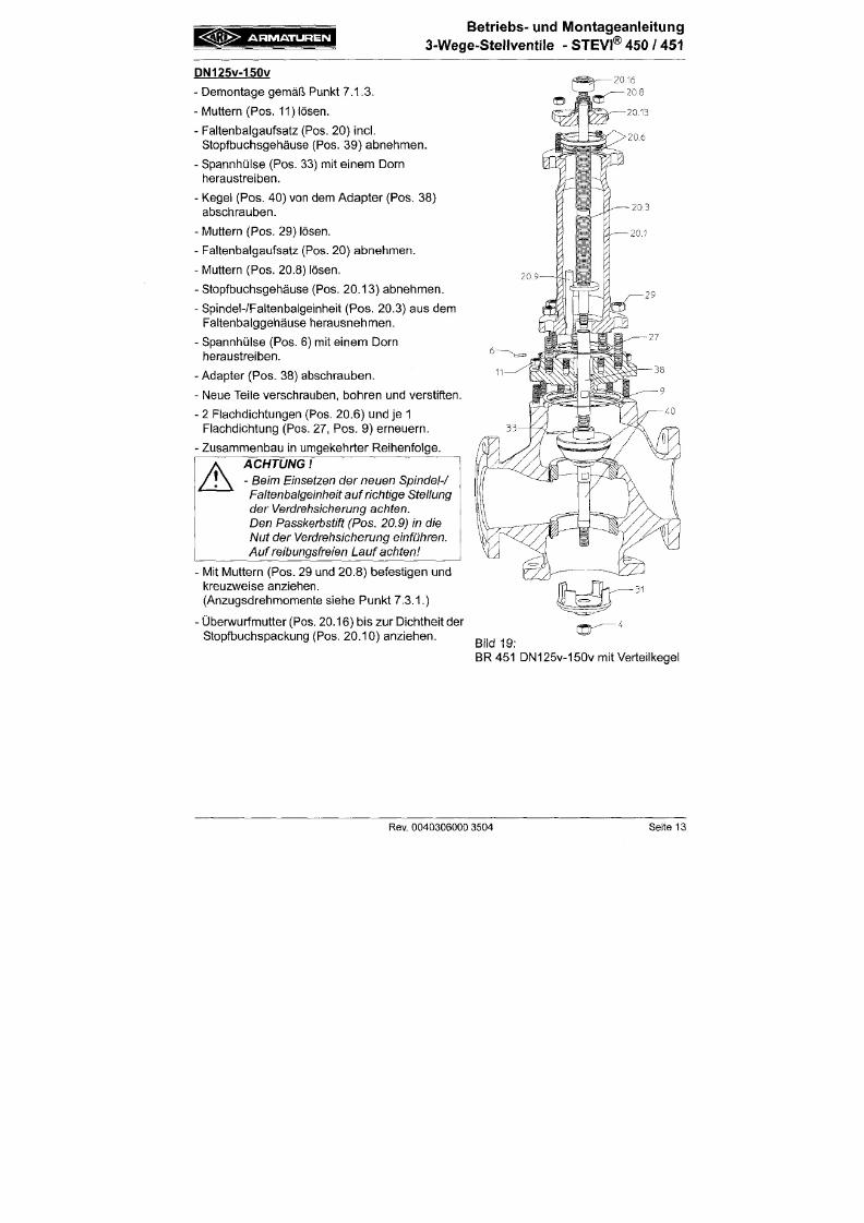
7/18/2019 M14 Thermal Fluid
http://slidepdf.com/reader/full/m14-thermal-fluid 174/486
heraustreiben.
- Kegel (Pos. 40) von dem Adapter (Pos. 38)
abschrauben.
- Mu ttern (Pos . 29) lösen.
- Fal tenbalgaufsatz (Pos. 20) abnehmen.
- Muttern (Pos. 20.8) lösen.
- Stopfbuchsgehäuse (Pos. 20.13) abne hm en.
- Spindel-ZFaltenbalgeinheit (Pos. 20.3) aus dem
Fal tenbalggehäuse herausnehmen.
- Spannhülse (Pos. 6) mit e ine m Dorn
heraustreiben.
- Adapter (Pos. 38) abschrauben.
- Neue Tei le verschraube n, bo hren und verst i ften.
- 2 Flachdichtungen (Pos. 20.6) und je 1
A R M A T U R E N
Betr iebs- und Montageanlei tung
3-W ege -Stellven tile - STEVI® 450 / 45 1
7.2 Austauscl i der Innengarni tur
A
ACHTUNG
Vor Demontage der Armatur Punkt 10.0 und 11.0 beachten.
-
Ant r ieb abbauen.
(Siehe Betriebsanleitung des Stel lantriebs )
Zum Herausschrauben des Si tzr ings (Pos. 2) ist e in Spezialschlüssel erforderl ich, der vom
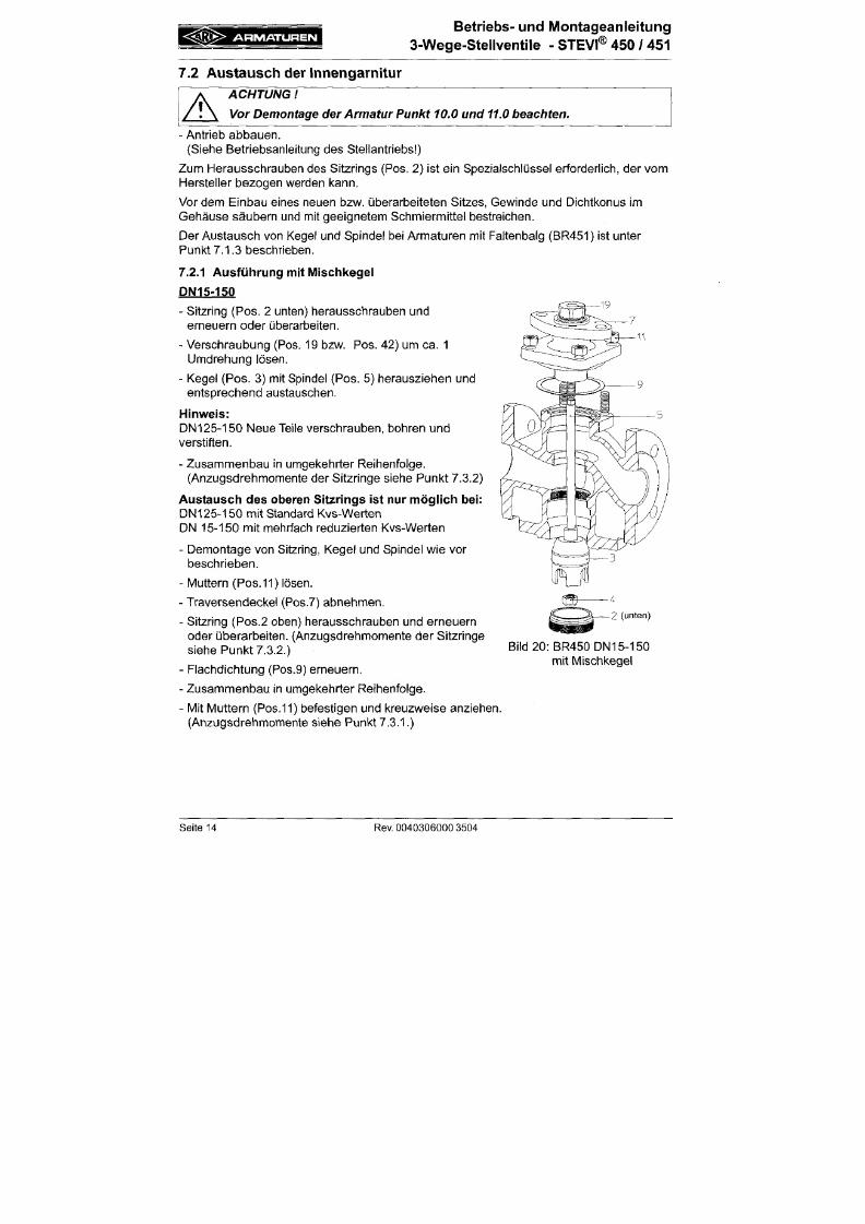
7/18/2019 M14 Thermal Fluid
http://slidepdf.com/reader/full/m14-thermal-fluid 175/486
Herstel ler bezogen werden kann.
Vor dem Einbau eines neuen bzw. überarbei teten Si tzes, Gewinde und Dichtkonus im
Ge häu se sä ubern und mi t geeignetem Schm iermi t te l best re ichen.
Der Austausch von Kegel und Spindel bei Armaturen mit Fal tenbalg (BR451) ist unter
Punkt 7.1.3 beschrieben.
7.2.1 Ausführung mit Mischkegel
D N 1 5 - 1 5 0
- Si tzr ing (Pos. 2 unten) herausschrauben und
erneuern oder überarbei ten.
- Vers chra ubu ng (Pos. 19 bzw. Pos. 42) um ca. 1
Umdrehung lösen.
- Kegel (P os. 3) mit Spindel (Po s. 5) heraus ziehen und
entsprec hend austauschen.
Hinwels:
g M f e > A R M A T U R E N
Betr iebs- und M ontageanle itung
3-Wege-Steliventile
- STEVI® 450 / 451
DN125v-150v
- Sitzring (Pos. 2 unten) herausschrauben und
erneuern oder überarbeiten.
- M uttern (Pos. 24) um ca. 2-3 Umdrehungen
lösen.
- Kegel (Pos. 3) mit Spindel (Pos. 5) herausziehen
und entsprechend austauschen.
2(oben)
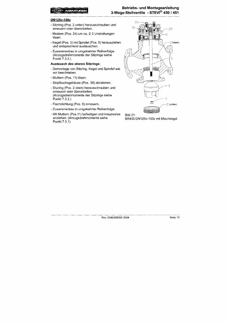
7/18/2019 M14 Thermal Fluid
http://slidepdf.com/reader/full/m14-thermal-fluid 176/486
- Zusammenbau in umgel<ehrter Reihenfolge.
(Anzugsdrehmomente der Sitzringe siehe
Punkt 7.3.2.)
Austausch des oberen Sitzrings:
- Demontage von Sitzring, Kegel und Spindel wie
vor beschrieben.
- M uttern (Pos. 11) lösen.
- Stopfbuchsgehäuse (Pos. 39) abnehmen.
- Sitzring (Pos. 2 oben) herausschrauben und
erneuern oder überarbeiten.
(Anzugsdrehmomente der Sitzringe siehe
Punl<t
7.3.2.)
- Flachdichtung (Pos. 9) erneuern.
- Zusam menbau in umgel<ehrter Reihenfolge.
2 (unten)
= K Q * >
ARMATUREN
Betr iebs- und Montageanle i tung
3-W ege -Stellventile - STEVI® 450 / 451
7.2.2 Ausführung mit Verteilkegel
DN40-150
- Verschraubu ng (Pos. 19 bzw. Pos. 42 ) um ca. 1
Umdrehung lösen.
- Muttern (Pos. 11) lösen.
- Traversendeckel (Pos.7) abheben.
- Mutter (Pos. 4) lösen.
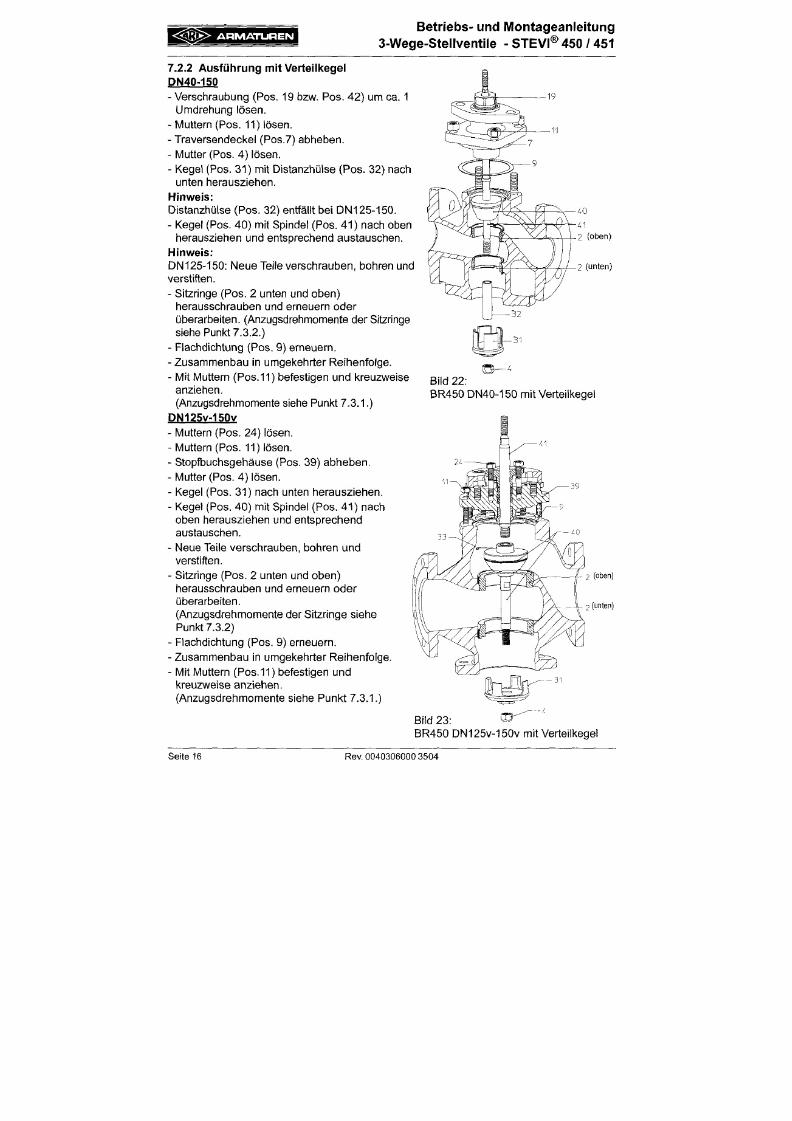
7/18/2019 M14 Thermal Fluid
http://slidepdf.com/reader/full/m14-thermal-fluid 177/486
- Kegel (Pos. 31) mit Distanzhülse (Po s. 32) nach
unten herausziehen.
Hinweis:
Distanzhülse (Po s. 32) entfäl lt bei DN 125 -150.
- Kegel (Pos. 40) mit Spindel (Pos. 41) nach oben
herausziehen und entsprechend austauschen.
Hinweis:
DN125-150: Neue Tei le verschrauben, bohren und
verstif ten.
- Sitzringe (Pos. 2 unten und oben)
herausschrauben und erneuern oder
übera rbeiten. (Anzugsdrehm omente der Sitzringe
siehe Punkt 7.3.2.)
- Flachdichtung (Pos. 9) erneu ern.
- Zusammenbau in umgekehrter Reihenfolge.
- Mit Muttern (Pos.11) befest igen und kreuzweise
2 (unten)
A R M A T U R E N
Betr iebs- und M ontageanle itung
3-Wege-Stellventile
- STEVI® 450 / 451
7.3 Anzugsdrehmomente
7.3.1 Anzugsdrehmomente der Sechskantmuttern
M 1 0 = 1 5 - 3 0 N m
M 12 = 35 -50 Nm
M 1 6 = 8 0 - 1 2 0 N m
M 20 = 150-200 Nm
7/18/2019 M14 Thermal Fluid
http://slidepdf.com/reader/full/m14-thermal-fluid 178/486
7.3.2 Anzugsdrehmomente der Sitzringe
DN 15/20
DN 25/ 32
DN
40/ 50
DN65
DN80
DN100
DN125/125V
DN150/150V
=
=
=
=
=
=
=
=
100 Nm
150 Nm
350 Nm
480 Nm
660 Nm
980 Nm
1450 Nm
2000 Nm
/
A ntriebsaufbau siehe Betriebsan leitung für betreffenden
Antrieb
i ß ß > A R M A T U R E N
Betriebs- und Montageanleitung
3-Wege-Stellventile - STEVI® 45 0 / 45 1
9 . 0 F e h l e r s u c h p l a n
A
ACHTUNG
- vor Mo ntage- und Reparaturarbeiten Punkte 10.0 und 11.0 beachten
- vor Wiederinbetriebnahme Punkt
6.0
beachten
S t ö ru n g
Kein Durchfluss
Mö g f ich e Ursach en
Armatur gesctilossen
Abhi l fe
Armatur öffnen (mittels An trieb)
7/18/2019 M14 Thermal Fluid
http://slidepdf.com/reader/full/m14-thermal-fluid 179/486
Geringer Durclifluss
Spindel bewegt sicti nur
rucl<weise
Spindel bzw. Kegel sitzt
fest
Flansctiabdeckungen wu rden nicht ent
fernt
Armatur nicht ausreichend geöffnet
Verunreinigter Schmutzfänger
Verstopfung im Rohrleitungssystem
Armatur bzw. Kvs-W ert falsch gewä hlt
Zu fest angezogene Stopfbuchsabdich
tung (bei Armaturen mit Graphit-
Packung)
Kegel hat aufgrund von Fest-, Schm utz
partikeln leicht gefressen
Sitz und Kegel stark mit Schmutz ver
klebt, insbesondere bei Schlitz- und
Lochkegeln
Flanschabdeckungen entfernen
Armatur öffnen (mittels Antrieb)
Sieb reinigen / austauschen
Rohrieitungssystem überprüfen
Armatur mit größerem Kvs-Wert einset
zen
Geringes Lösen der Verschraubung
(Pos. 42/20.17) bzw. der IMuttern
(Pos. 24)
Jedoch
muss Dichtheit
gewährleistet bleiben
Innenteile säubern, beschädigte Stellen
glätten
Sitz und Kegel mit geeignetem
Lösungsmittel reinigen
A R M A T U R E N
Betriebs- und Montageanleitung
3-Wege-Stellventile
- STEVI®
450
/ 451
10.0 Dem ontage der A rm a tu r bzw. des Ob er te i les
A
ACHTUNG
Insbesondere sind folgende Punkte zu beachten:
-
Druckloses Rohrleitungssystem.
- Abgekühltes Medium.
-
Entleerte
A nlage.
7/18/2019 M14 Thermal Fluid
http://slidepdf.com/reader/full/m14-thermal-fluid 180/486
- Bei ätzenden, brennbaren, aggressiven oder toxischen Medien Rohrleitungs
system
be lüften.
11.0 Garant ie / Gewähr le is tung
Umfang und Zeitraum der Gewährleistung ist in der zum Zeitpunkt der Lieferung gültigen
Ausgabe der "Allgemeinen Geschäftsbedingungen der Albert Richter GmbH & Co. KG"
oder abweichend davon im Kaufvertrag selbst angegeben.
Wir leisten Gewähr für eine
dem
jew eiligen Stand der Technik und dem bestätigten Verwen
dungszweck entsprechenden Fehlerfreiheit.
Für Schäden, die durch unsachgemäße Behandlung oder Nichtbeachtung der Betriebs
und Montageanleitung, des Katalogblattes und der einschlägigen Regelwerken entstehen,
können keine Gewährleistungsansprüche geltend gemacht werden.
Schäden die während des Betriebes, durch vom Datenblatt oder anderen Vereinbarungen
abweichenden Einsatzbedingungen entstehen, unterliegen ebenso nicht der Gewährleis
Betr iebs- und M ontageanlei tung
3-Wege-Steliventile
- STEVI®
45 0
/ 451
1 2 . 0 K o n f o r m i t ä t s - / H ers t e l l e re rk lä rung
ARI-Armaturen A lbert Richter GmbH & C o. KG,
Mergelhejde 56-60, 33756 Schloß Holte-Stukenbrock
EG-Konformitätserklärung
im Sinne der
EG-Druckgeräterichtlinie 97/23/EG
7/18/2019 M14 Thermal Fluid
http://slidepdf.com/reader/full/m14-thermal-fluid 181/486
Hierm it erklären wir,
das s gem äß der oben genannten Druckgeräterichtlinie, die unten aufgelisteten Produkte ausgeführt
sind und nach Diagramm 6, Anhang II, M odul H von LLOYD'S RE GISTER QUALITY ASSUR ANC E
(BS-Nr.
0525), Mönckebergstr. 27, 20095 H am burg, geprüft wurden.
Zertifikat-Nr: 50003/1
Stellventi l in Dreiwegeform
Typ 45 0 ,
4 5 1 ,
423, 463, 483
Angewendete Normen:
DIN EN 60534 Teil 1
VDI/VDE 3844 Blatt 1
DIN 3840
AD 2000 M erkblatt A4
g3 iS> A R M A T U R E N
Operating and installation instructions
3-way co n tro l va lves - STEVI® 450 / 451
7/18/2019 M14 Thermal Fluid
http://slidepdf.com/reader/full/m14-thermal-fluid 182/486
CTZD
A R M A T U R E N
Operating and installation instructions
3-way
con trol valves - STEVI® 450 / 451
1.0 Ge nera l in fo rm at io n on op era t ing ins t ru c t io ns
These operating instructions provide information on mounting and maintaining the fittings.
Please contact the supplier or the manufacturer in case of problems which cannot be
solved by reference to the operating instructions.
They are binding on the transport, storage, installation, start-up, operation, maintenance
and repair.
The notes and warnings must be observed and adhered to.
- Handling and all work must be carried out by expert personnel or all activities must be

7/18/2019 M14 Thermal Fluid
http://slidepdf.com/reader/full/m14-thermal-fluid 183/486
supervised and checked.
It is the owner's responsibility to define areas of responsibility and competence and to
monitor the personnel.
- In addition, current regional safety requirements must be applied and observed when
taking the fittings out of service as well as when maintaining and repairing them.
The manufacturer reserves the right to introduce technical modifications at any time.
These Operating Instructions comply with the requirements of ED Directives.
2.0 Notes on poss ib le dangers
2.1 Significance of symbols
A
ATTENTION
Warning of general danger.
A R M A T U R E N
Operat ing and insta l la t ion instruc t ions
3-way
co ntrol val ve s - STEVI® 450 / 451
4 . 0 D e s c r i p t i o n
4.1 Scope of appl icat ions
Valves are used for „controlling the flow of liquids, gases and vapours in chemical and other
processing plants and for plant engineering".
ATTENTION
- Refer to the data sheet for applications, iimits on use and possibilities.
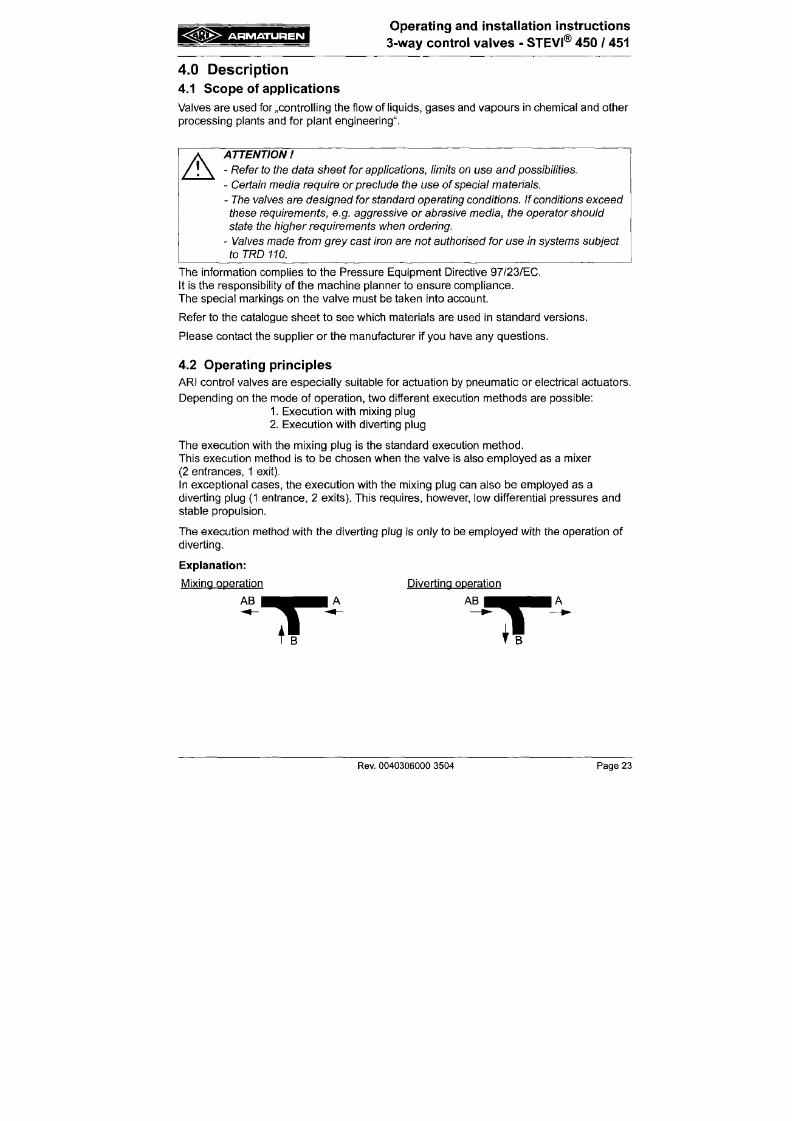
7/18/2019 M14 Thermal Fluid
http://slidepdf.com/reader/full/m14-thermal-fluid 184/486
A
- Certain media require or preclude the use of special materials.
- The valves are designed forstandard operating conditions. If conditions exceed
these requirements,
e.g.
aggressive
or
abrasive
m edia, the
operator should
state the higher requirements when ordering.
-
Valves made
from grey cast
iron
are not
authorised
fo r
use
in
systems
subject
to TRD
110.
The information complies to the Pressure Equipment Directive 97/23/EC.
It is the responsibility of the machine planner to ensure compliance.
The special markings on the valve must be taken into account.
Refer to the catalogue sheet to see which materials are used in standard versions.
Please contact the supplier or the manufacturer if you have any questions.
4.2 Operat ing principles
g Ö > > A R M A T U R E N
Operat ing and insta l la t ion instruc t ions
3-way c on tr o l valves - STEVI® 450 / 451
4.3 Diagram
4.3.1 Mixing plug design
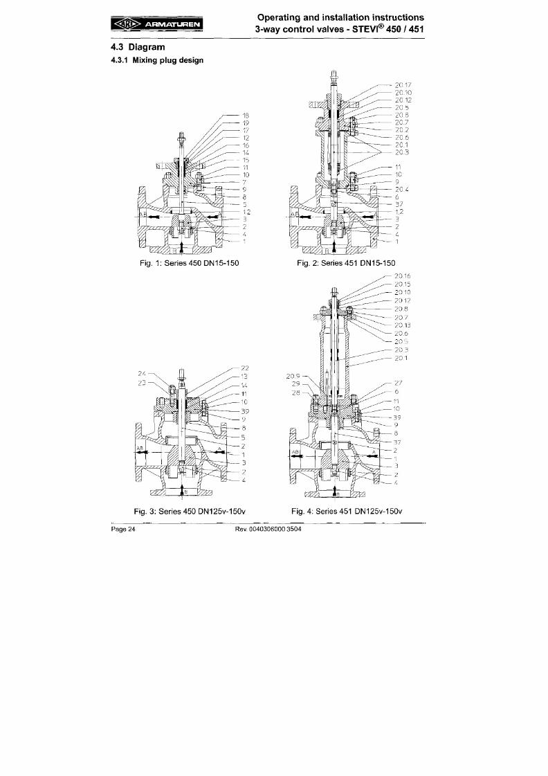
7/18/2019 M14 Thermal Fluid
http://slidepdf.com/reader/full/m14-thermal-fluid 185/486
1 iSe r ies 450 D N15-150
i : ^ i « > A R M A T U R E N
Operat ing and insta l la tion instru ct ion s
3-way co ntro l va lve s - STEVI® 450 / 451
4.3.2 Diverting plug design
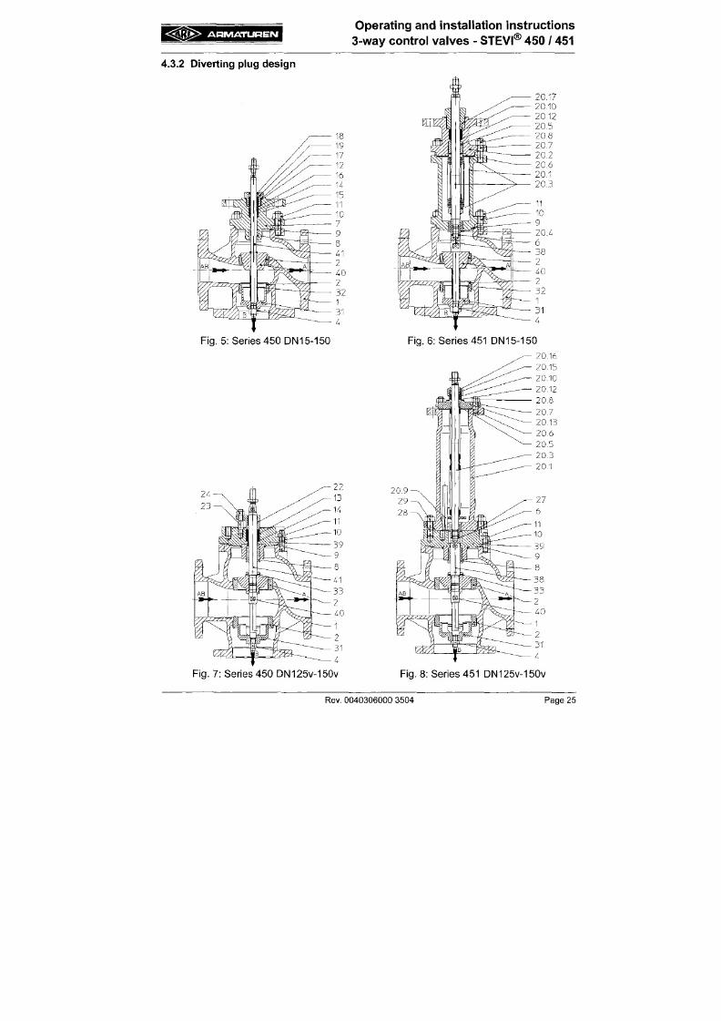
7/18/2019 M14 Thermal Fluid
http://slidepdf.com/reader/full/m14-thermal-fluid 186/486
Series 450 DN15-150
Fig.
6 : Ser ies 451 DN15-150
< S 3 ^ A R M A T U R E N
Operating and instal lat ion instruct ions
3-way c on tro l va lves - STEVI® 450 / 451
4.4 Technical data
for
- Principal dimensions
- Pressure-temperature-rat ings, etc. refer to datasheet.
4.5 Marking
Type-Number
Nominal diameter
Manufacturer CE-marking
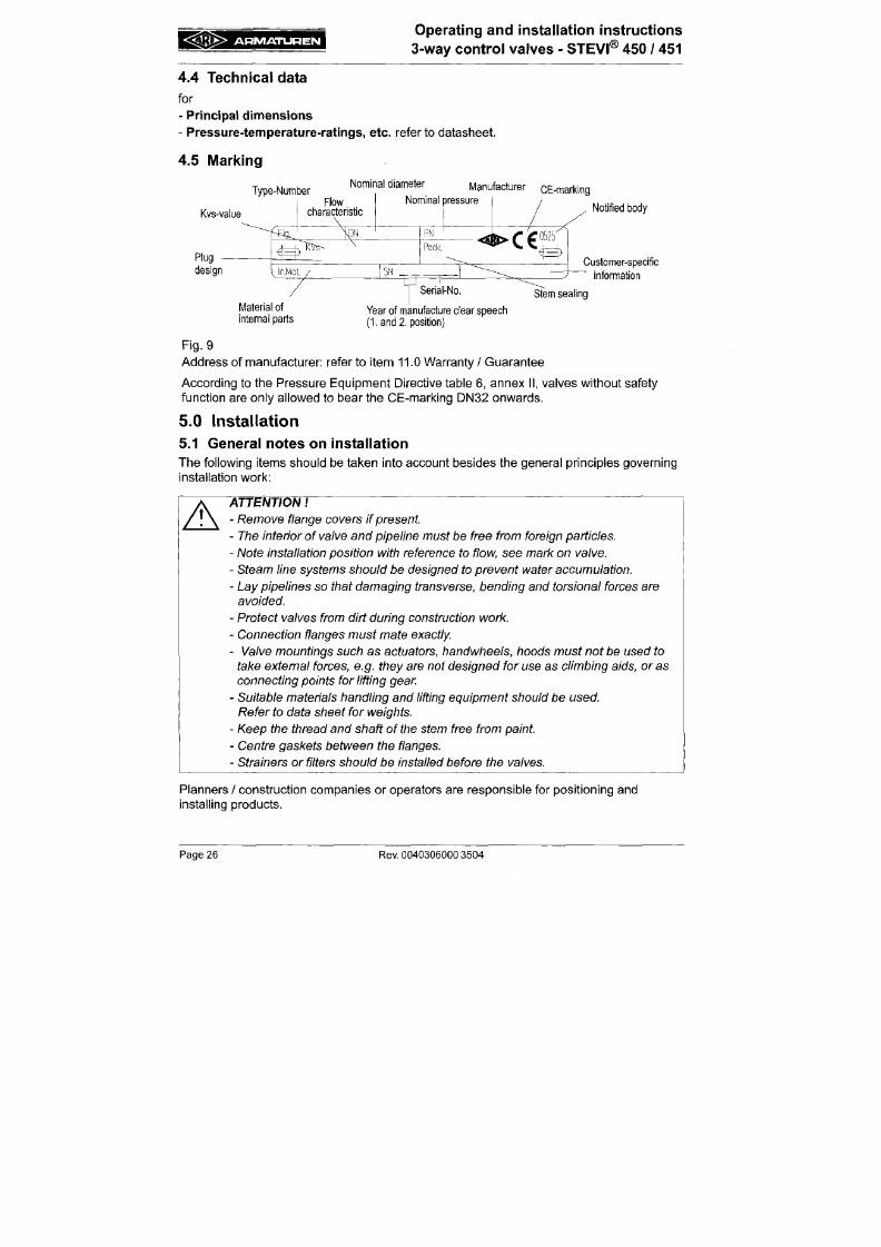
7/18/2019 M14 Thermal Fluid
http://slidepdf.com/reader/full/m14-thermal-fluid 187/486
Kvs-value
Notified body
Customer-specific
information
Stem
sealing
IVIaterial
of
internal parts
Year of manufacture clear speech
(1.
and
2. position)
Fig. 9
Address of manufacturer: refer to i tem 11.0 Warranty / Guarantee
Acco rding to the Pressure Equ ipmen t D irect ive table 6, annex I I , valves withou t safety
funct ion are only al lowed to bear the CE-marking DN32 onwards.
5.0 Instal lat ion
= : K ( I K > ARMATUREN
Operating and instal lat ion instruct ions
3-way con tro l va lve s - STEVI® 450 / 451
5.2 Requirements at the place of instal lation
The place of instal lat ion should be easi ly accessible and provide ample space for
maintena nce and remo ving the actuator. Stop valves should be instal led before and behind
the control valve to enable maintenance working without draining the piping system. The
valve should preferably installed vertically with the actuator at the top. Inclined or horizontal
installation without supports is permissible only with l ight actuators.
For this installation pos i t ion, the two distan ce columns (or joke ) have to be above each
other in the vertical plane.
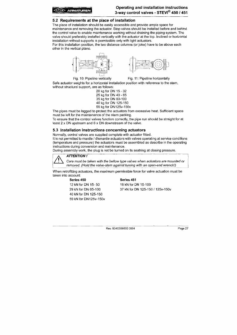
7/18/2019 M14 Thermal Fluid
http://slidepdf.com/reader/full/m14-thermal-fluid 188/486
X U ,
a
Fig.
10: Pip eline vertically Fig. 11 : Pip eline horizontally
Safe actuator weights for a horizontal installation position with reference to the stem,
without structural support, a re as fol lows:
20 kg for DN 1 5 -3 2
25 kg for D N 40 - 65
35 kg for DN 80-100
40 kg for DN 125-150
5 5 k g f o r D N 1 2 5 v - 1 5 0 v
The pipes must be lagge d to protect the actuators from exces sive heat. Suffic ient sp ace
A R M A T U R E N
Operating and installation instructions
3-way
contro l valves - STEVI® 450 / 451
6.0 Pu t t ing th e valve in to ope rat io n
A
ATTENTION
- Before putting the valve into operation, check material, pressure, temperature
and direction of
flow.
- Regional safety instructions must be adhered to.
- Residues in piping and valves (dirt, weld beads, etc.) inevitably lead to leal<age.
-
Touching
the
valve when
it is
operating
at
high
(> 50
°C) or low (<
0
°C)
media
temperatures can cause injury.
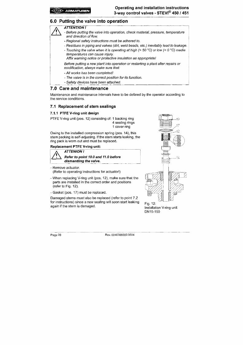
7/18/2019 M14 Thermal Fluid
http://slidepdf.com/reader/full/m14-thermal-fluid 189/486
Affix
warning notice
or
protective insulation
as appropriate
Before putting a new plant into operation o r restarting a plant after repairs or
modification, always make sure that:
- A ll works has
been
completed
- T he valve is in
the correct position
for
its
function.
- Safety devices have been
attached.
7.0 Care an d m aintenan ce
IVIaintenance and maintenance intervals have to be defined by the operator according to
the service cond itions.
7.1 Replacement of stem sealings
7.1.1 PTFE V-ring unit design
Operating and installation instructions
3-way control valves - STEVI® 450 / 451
7.1.2 Stuffing box packing design
The stuff ing box packing requires maintenance.
If leaks develop, imm ediately t ighten th e screw joint (pos. 42 ) respect ively the he xago n nuts
(pos.
24) gradually unti l the packing ring (pos. 13) stops leaking.
The service l i fe of stuffing box packings (pos. 13) can be Increased by checking regularly
leakage.
If leaks can no long er be stopped by t ightening the screw joint (pos. 42) respe ct ively the
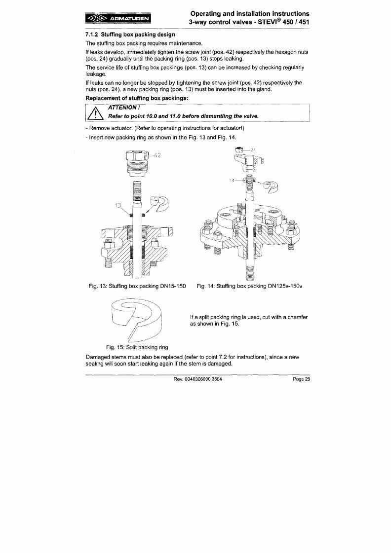
7/18/2019 M14 Thermal Fluid
http://slidepdf.com/reader/full/m14-thermal-fluid 190/486
nuts (pos. 24), a new packing r ing (po s. 13) must be Inserted Into the gland .
Replacement of stuff ing box packings:
A
ATTENION
Refer to point 10.0 and 11.0 before dismantling the valve.
Rem ove actuator. (Refer to ope rat ing Instruct ions for actu ator )
Insert new packing ring as shown in the Fig. 13 and Fig. 14.
A R M A T U R E N
Operat ing and insta l lat ion inst ruct ions
® .
3-way contro l valves - S T E V r 450 / 451
7.1.3 Bellows seal des ign
I f the stem leaks the b el lows seal (pos. 20.3) is defect ive. The leak can ini tially be stopped
by t ighten ing the screw joint (pos. 20.17) respec t ively the sleeve nut (pos. 20.1 6).
Stem and bel lows (pos. 20.3) can only be replaced together.
Replacement of bel lows
seal:
ATTENION
Refer to point 10.0 and 11.0 before dismantling the valve.
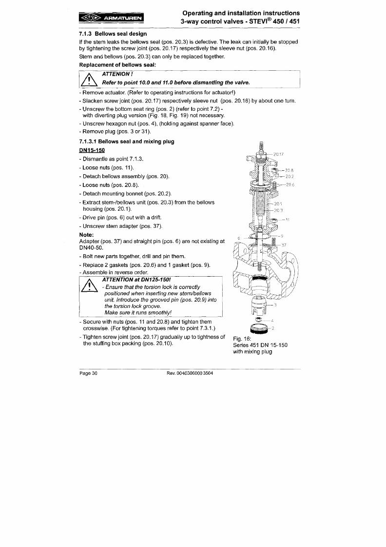
7/18/2019 M14 Thermal Fluid
http://slidepdf.com/reader/full/m14-thermal-fluid 191/486
A
20,17
- Re m ove actuator. (Refer to operat ing instruct ions for actua tor )
- Slack en screw joint (pos. 20.17) respect ively sleeve nut (pos, 20.16) by abou t one
turn.
- Unscrew the bottom seat ring (pos. 2) (refer to point 7.2) -
with diverting plug version (Fig. 18, Fig. 19) not necessary.
- Unscrew hexagon nut (pos. 4), (holding against spanner face).
- Remove plug (pos. 3 or 31).
7.1.3.1 Bellows seal and mixing plug
P N I 5 - 1 5 0
- Dismantle as point 7.1.3.
- Loose nuts (pos. 11).
- Detach bel lows assembly (pos. 20).
- Loose nuts (pos. 20.8).
< Ä Q X >
ARMATUREN
Operating and installation instructions
3-way control valves - STEVI® 45 0 / 45 1
DN125v-150v
- Dismantle as point 7.1.3.
- Loose nuts (pos. 29 ).
- Detach bel lows assembly (pos. 20).
- Loose nuts (pos. 20.8 ).
- Detach stuff ing box housing (pos. 20.13).
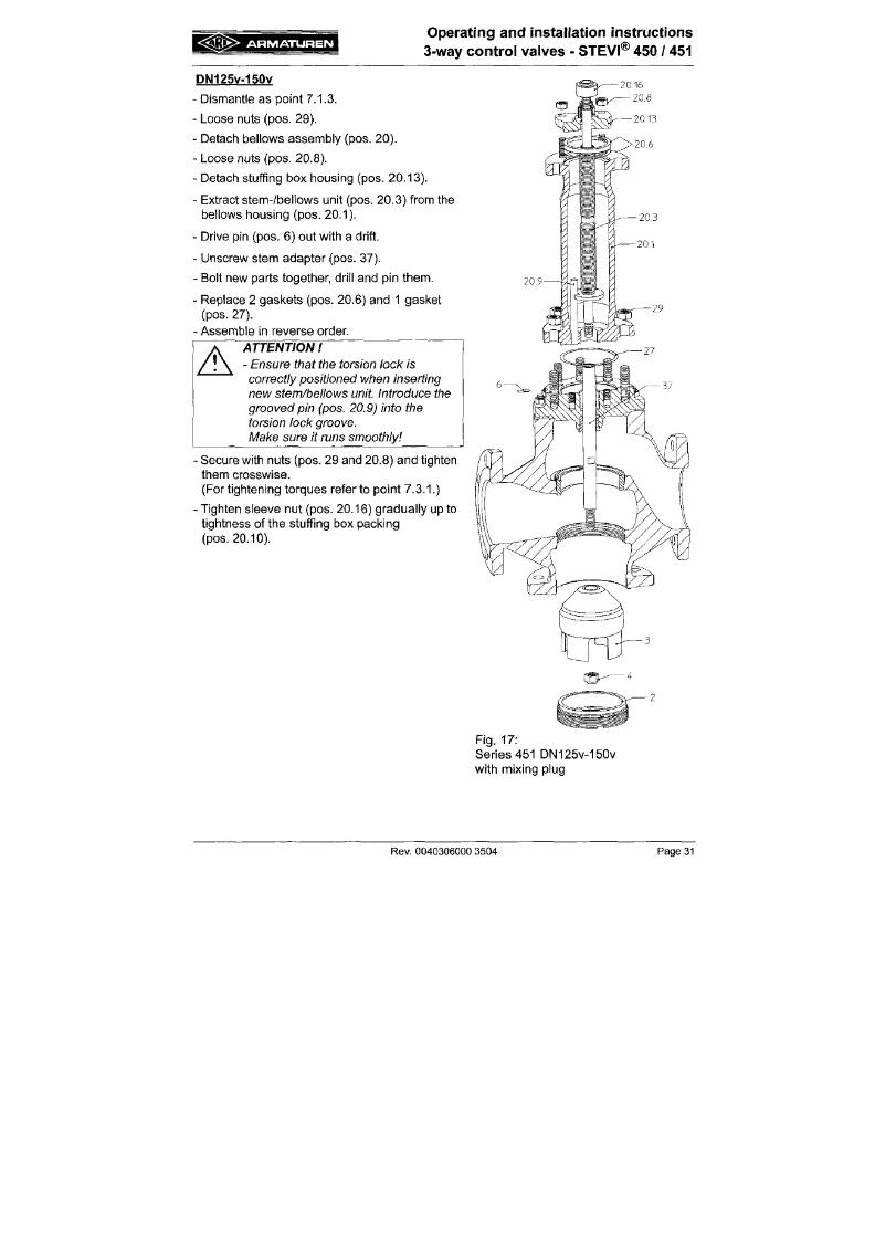
7/18/2019 M14 Thermal Fluid
http://slidepdf.com/reader/full/m14-thermal-fluid 192/486
- Extract stem-/be l lows unit (pos. 20.3) from the
bel lows housing (pos. 20.1).
- Drive pin (pos. 6) out with a drift.
- Unscrew stem adapter (pos. 37).
- Bolt new parts together, dri l l and pin them.
- Replace 2 gaskets (pos. 20.6) and 1 gasket
(pos. 27).
- Assemble in reverse order.
A
ATTENTION
- Ensure that the torsion lock is
correctly positioned when inserting
new stem/beliows unit Introduce the
grooved pin (pos. 20.9) into the
A R M A T U R E N
Operat ing and insta l lat ion inst ruct ions
3-way co ntr ol v alv es - STEVI® 450 / 451
7.1.3.2 Bellows seal and diverting plug
DN40-150
- Dismantle as i tem 7.1.3.
- Pul l distance bush (po s. 32) from adapter (pos. 38).
Note:
There is no distance bush (pos. 32) on DN 125-150.
- Loose nuts (pos. 11).
20,17
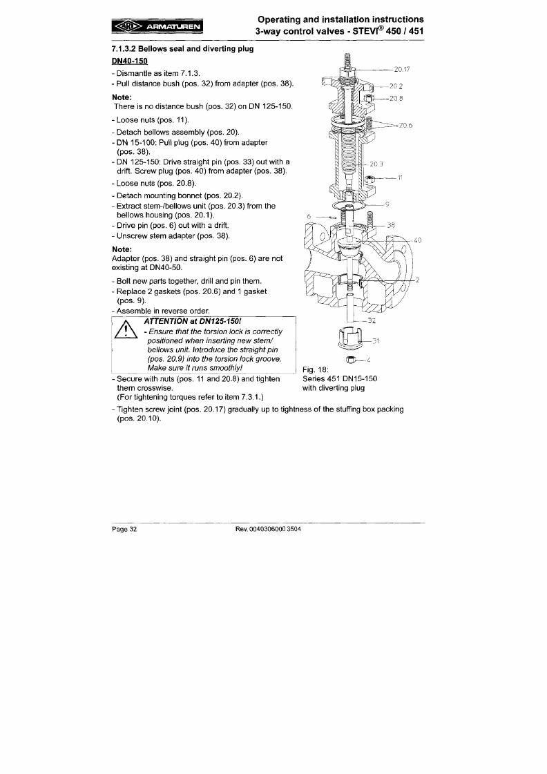
7/18/2019 M14 Thermal Fluid
http://slidepdf.com/reader/full/m14-thermal-fluid 193/486
- Detach bel lows assembly (pos. 20).
- DN 15-100: Pul l plug (pos. 40) from adapter
(pos.
38).
- DN 125-150: Drive straight pin (pos. 33) out with a
drift. Screw plug (pos. 40) from adapter (pos. 38).
- Loose nuts (pos. 20.8).
- Detach mounting bonnet (pos. 20.2).
- Extract s tem-/bel lows unit (pos. 20.3) from the
bel lows housing (pos. 20.1).
- Drive pin (pos. 6) out with a drift.
- Unscrew stem adapter (pos. 38).
Note:
Ad apte r (pos. 38) and straight pin (pos. 6) are not
A R M A T U R E N
Operating and installation instructions
3-way control valves - STEVI® 450 / 451
DN125v -150v
- Dismantle as item 7.1.3.
- Loose nuts (pos. 11).
- Detach bellows assembly (pos. 20 ) i n d .
stuffing box housing (pos. 39).
- Drive pin (pos. 33) out with a drift.
- Unscrew plug (pos . 40) from ad ap ter (pos. 38).
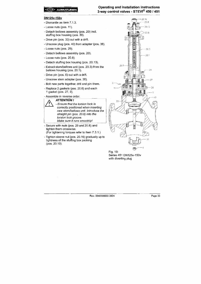
7/18/2019 M14 Thermal Fluid
http://slidepdf.com/reader/full/m14-thermal-fluid 194/486
- Loose nuts (pos. 29).
- Detach bel lows assembly (pos. 20).
- Loose nuts (pos. 20.8).
- Detach stuff ing box housing (pos. 20.13).
- Extract stem/bel lows unit (pos. 20.3) from the
bel lows housing (pos. 20.1).
- Drive pin (pos. 6) out with a drift.
- Unscrew stem adapter (pos. 38).
- Bolt new parts together, dri l l and pin them.
- Replace 2 gaskets (pes. 20.6) and each
1 gasket (pos. 27, 9).
- Assemble in reverse order.
g © Ä > A R M A T U R E N
Operat ing and insta l la t ion instruct ions
3-way co ntro l valve s - STEVI® 450 / 451
7.2 Replacement of internal parts
A
ATTENION
Refer to item 10.0 and 11.0 before dismantling the valve.
-
Remove actuator. (Refer to operat ing instruct ions for actuator )
A special wrench is needed to remove the seatr ing (pos. 2). I t can be obtained from the
manufacturer .
When f i t t ing a new or recondit ioned seatr ing, clean thread and seal ing taper in body and
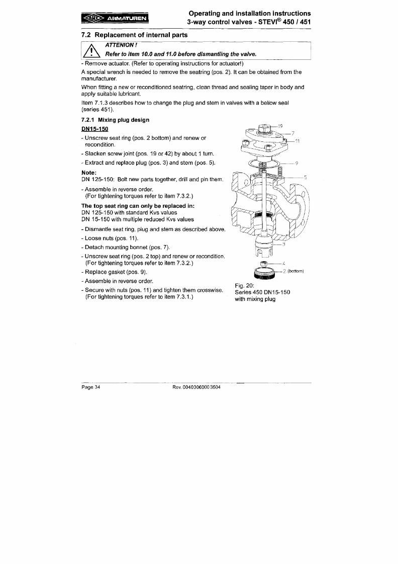
7/18/2019 M14 Thermal Fluid
http://slidepdf.com/reader/full/m14-thermal-fluid 195/486
apply sui table lubricant.
I tem 7.1.3 describes how to change the plug and stem in valves with a bel low seal
(ser ies 451 ).
7.2.1 Mixing plug design
P N I 5 - 1 5 0
- Unscrew seat r ing (pos. 2 bottom) and renew or
recondi t ion.
- Slacken screw joint (pos. 19 or 42) by about 1 turn.
- Extract and replace plug (pos. 3) and stem (pos. 5).
Note:
DN 12 5-1 50 : Bolt new parts together, dr i l l an d pin them .
- Assemble in reverse order.
A R M A T U R E N
Operating and installation instructions
3-way control valves - STEVI® 450 / 451
DN125v-150v
- Unscrew seat r ing (pos. 2 bottom) and renew or
recondit ion.
- Slacken nuts (pos. 24) by about 2-3 turns.
- Extract and replace plug (pos. 3) and stem
(pos. 5).
- Assemble in reverse order.
(For tightening torques refer to item 7.3.2.)
2 (top)
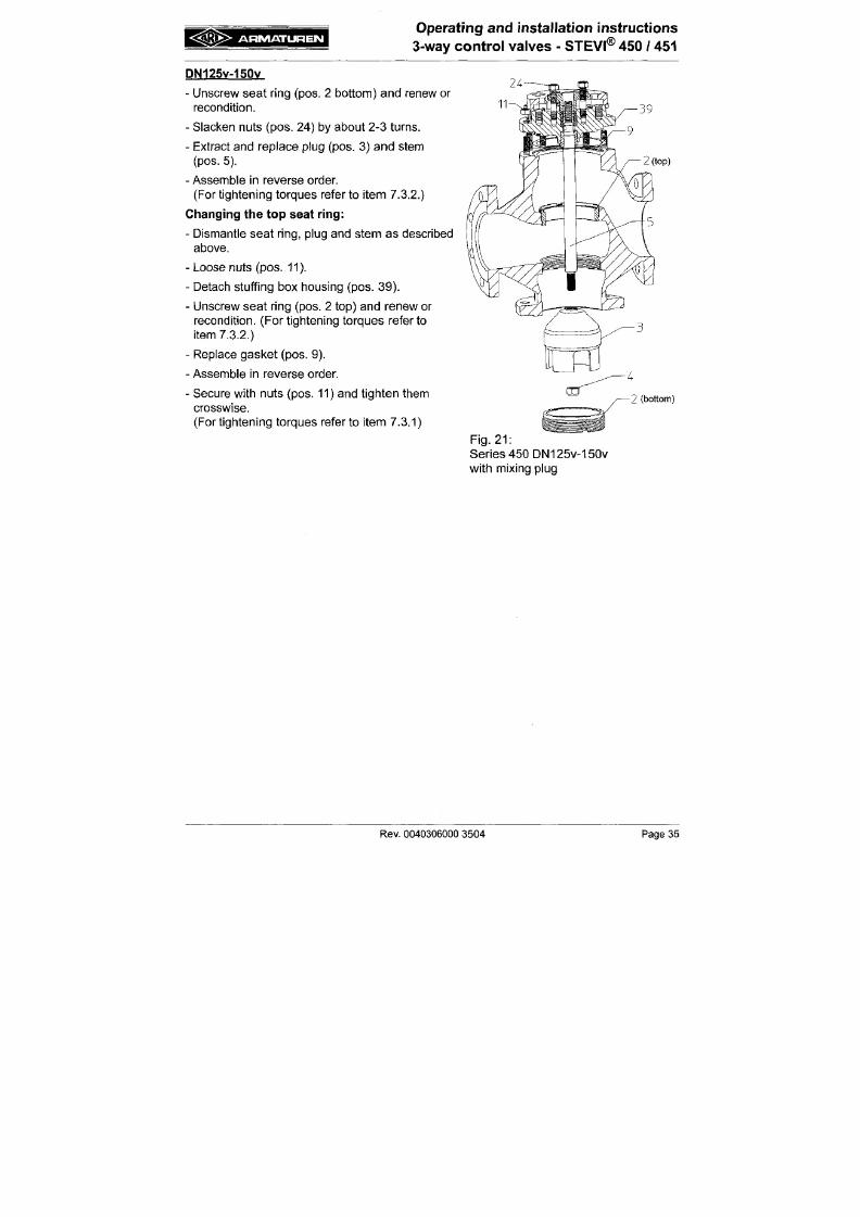
7/18/2019 M14 Thermal Fluid
http://slidepdf.com/reader/full/m14-thermal-fluid 196/486
Changing the to p seat r ing:
- Dismantle seat r ing, plug and stem as described
above.
- Loose nuts (pos. 11).
- Detach stuff ing box housing (pes. 39).
- Unscrew seat r ing (pes. 2 top) and renew or
recondit ion. (For t ightening torq ues refer to
item 7.3.2.)
- Replace gasket (pos. 9).
- Assemble in reverse order
- Secure with nuts (pos. 11) and t ighten them
crosswise.
2 (bottom)
A R M A T U R E N
Operat ing and insta l la t ion instruc t ions
3-way co ntro l va lve s - STEVI® 450 / 451
7.2.2 Diverting plug de sign
DN40-150
- Slacken screw joint (pos. 19 and 24) by about 1
turn.
- Loose nuts (pos. 11).
- Detach mounting bonnet (pos. 7).
- Loose nut (pos. 4) and pull plug (pos. 31) with
distance bush (pos. 32) down.
Note:
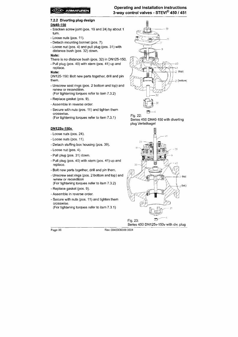
7/18/2019 M14 Thermal Fluid
http://slidepdf.com/reader/full/m14-thermal-fluid 197/486
There is no distance bush (pos. 32) in DN125-150.
- Pul l plug (pos. 40) with stem (pos. 41) up and
replace.
Note:
DN
125 -15 0: Bolt new p arts together, dri l l and pin
them.
- Unscrew seat r ings (pos. 2 bottom and top) and
renew or recondit ion.
(For tightening torques refer to item 7.3.2)
- Replace gasket (pos. 9).
- Assemble in reverse order.
- Secure with nuts (pos. 11) and t ighten them
crosswise.
2 (bottom;
A R M A T U R E N
Operating and installation instructions
3-way
con tro l valves - STEVI®
450
/ 451
7.3 Tightening torques
7.3.1 Tightening torques for hexagon nuts
M 1 0 = 1 5 - 3 0 N m
M 1 2 = 3 5 - 5 0 N m
M 16 = 8 0 - 1 2 0 Nm
M 20 = 150 -200 Nm
7.3.2 Tightening torques for seat rings
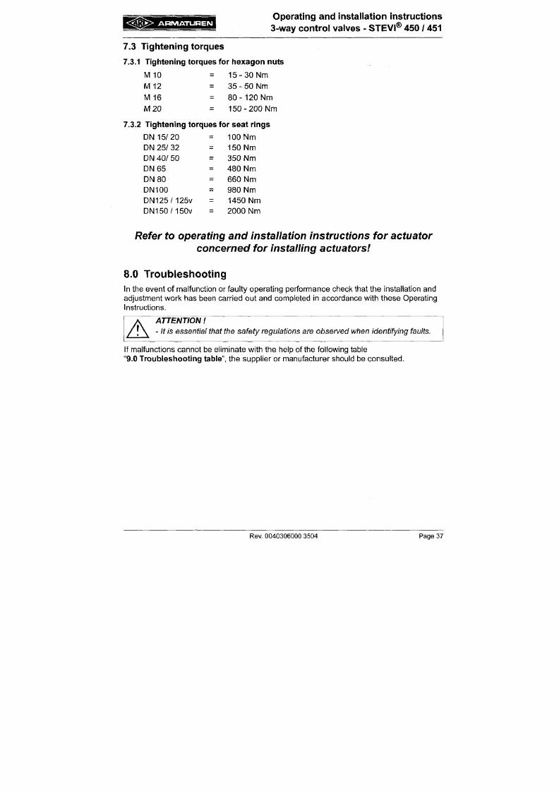
7/18/2019 M14 Thermal Fluid
http://slidepdf.com/reader/full/m14-thermal-fluid 198/486
DN 15 /20
DN 25/ 32
DN 40/ 50
D N 6 5
D N 8 0
DN100
D N 1 2 5 / 1 2 5 V
D N 1 5 0 / 1 5 0 V
=
=
=
=
=
=
=
=
100 Nm
150 Nm
350 Nm
480 Nm
660 Nm
980 Nm
1450 Nm
2000 Nm
Refer to operating and installation instructions for actuator
concerned for installing actuators
A R M A T U R E N
Operating and installation instructions
3-way control valves - STEVI® 450 / 451
9.0 Troubleshooting table
A
ATTENTION
- read item 10.0 and 11.0 prior to dismantling and repair work
- read item 6.0 before restarting the plant
Fault
No flow
Possible cause
Valve closed
Flange covers
not
removed
Corrective m easures
Open valve (using actuator)
Remove flange covers
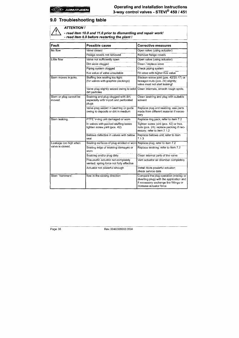
7/18/2019 M14 Thermal Fluid
http://slidepdf.com/reader/full/m14-thermal-fluid 199/486
Little flow
Stem m oves in jerks.
Stem
or
plug cannot
be
moved.
Valve
not
sufficiently ope n
Dirt sieve clogged
Piping system clogged
Kvs value
of
valve unsuitable
Stuffing box sealing too tight
(for valves with graph ite pacl<ings)
Valve plug slightly seized owing
to
solid
dirt particles
Seatring and plug clogged with dirt;
especially with V-port and perforated
plugs
Valve plug seized
in
seatring
or
guide
owing
to
deposits
or
dirt
in
medium
Open valve (using actuator)
Clean
/
replace sieve
Check piping system
Fit valve with higher Kvs value
Slacken screw joint (pos. 42/20 .17)
or
hexagon nuts (pos. 24) slightly;
valve must not start leaking
Clean internals, smooth rough spots.
Clean seatring and plug with suitable
solvent
Replace plug and sea tring; use parts
made from different material
if
neces
sary
A R M A T U R E N
Operating and installation instructions
3-way
control valves - STEVI® 450 / 451
10.0 Dism antling tlie valve or the top part
A
ATTENTION
The
following points must be
observed:
- Pressureless pipe system.
-
Medium must be
cool.
- Plant
must be
drained.
- Purge piping systems in case o f
caustic,
inflammable, aggressive or toxic
media.
7/18/2019 M14 Thermal Fluid
http://slidepdf.com/reader/full/m14-thermal-fluid 200/486
11.0 Warranty / Guarantee
The extent and period of warranty cover are specified in the "Standard Terms and
Conditions of Albert Richter GmbH & Co. KG" valid at the time of delivery or, by way o f
departure, in the contract of sale itself.
We guarantee freedom of faults in compliance with state-of-the-art technology and the
confirmed application.
No warranty claims can be made for any damage caused as the result of incorrect handling
or disregard of operating and installation instructions, datasheets and relavant regulations.
This warranty also does not cover any damage w hich occurs during operation under
conditions deviating from those laid down by specifications or other agreements.
Justified com plaints w ill be eliminated by repair carried out by us or by a specialist
A R M A T U R E N
Operating and instal lat ion instruct ions
3-way
control valves - STEVI®
45 0
/ 451
12 .0 EC dec la ra t ion o f conformi ty
/
iV Ianufacturers declarat ion
ARI-Armaturen Albert Richter GmbH & Co. KG,
Mergelheide 56-60, D-33756 Schloß Holte-Stukenbrock
declaration of conform ity EC
as defined by
the Pressure Equipment Directive 97/23/EC
Herewith we declare,
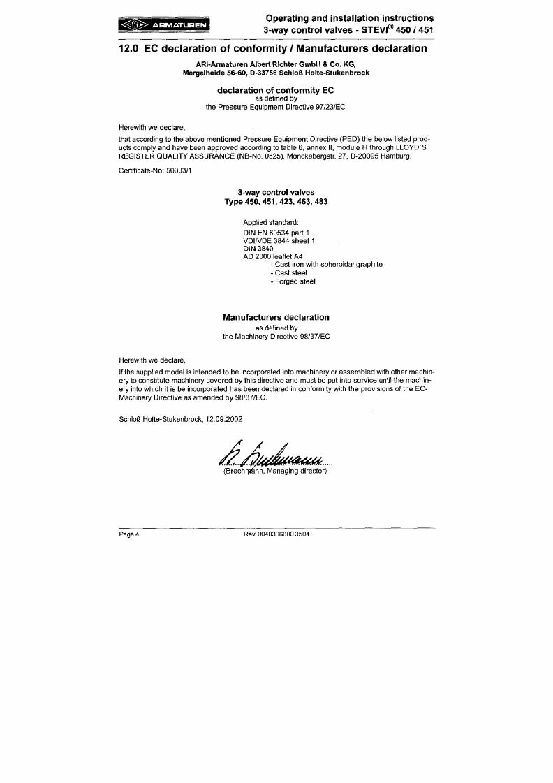
7/18/2019 M14 Thermal Fluid
http://slidepdf.com/reader/full/m14-thermal-fluid 201/486
that according to the above mentioned Pressure Equipmen t Directive (PED) the below listed prod
ucts comply and have been approved according to table 6, annex II, module H through LLOYD'S
REGISTER QU ALITY ASSU RANCE (NB-No. 0525), Mönckebergstr. 27, D-20095 Hamburg.
Certificate-No: 50003/1
3-way
control valves
Type 45 0, 45 1, 423, 463, 483
Applied standard:
DIN EN 60534 part 1
VDIA/DE 3844 sheet 1
DIN 3840
AD 2000 leaflet A4
- Cast iron with spheroidal graphite
A R M A T U R E N
Operating and Installation Instructions
Thrust Actuator A RI-P REM IO

7/18/2019 M14 Thermal Fluid
http://slidepdf.com/reader/full/m14-thermal-fluid 202/486
5.3 Instal lation inst ruc t ions for mo unt in g to valv es 16
5.3.1 M ount ing for valve- l i f t up to 30 mm (yoke ver s ion ) 16
5.3 .2 M ount ing for va lv e l if t over 30 mm to 80 mm (co lum n vers ion) 17
5.4 Elect r ical con ne ct ion 19
5.4 .1 Wir ing d iag ram AR I -PR EM IO 2.2 - 5 kN 19
5.4 .2 Wir ing d iagra m AR I -PR EM IO 12 -1 5 kN 20
5.4.2.1 ARI-PR EM IO 12 -1 5 kN 1 Ph~ / 3 Ph~ without reversing contactor 20
5.4.2.2 ARI-PR EM IO 12 -1 5 kN 1 Ph~ / 3 Ph~ with reversing contactor 21
5.4.3 Con nect ion 22
5.5 Se tt ings : 23
5.5.1 Torque and t rave l switch es - s tand ard featu re 23
5.5.2 Con nect ion boa rds PA or NA (only 2.2 - 5 kN) 23
5.5.3 Travel switch 24
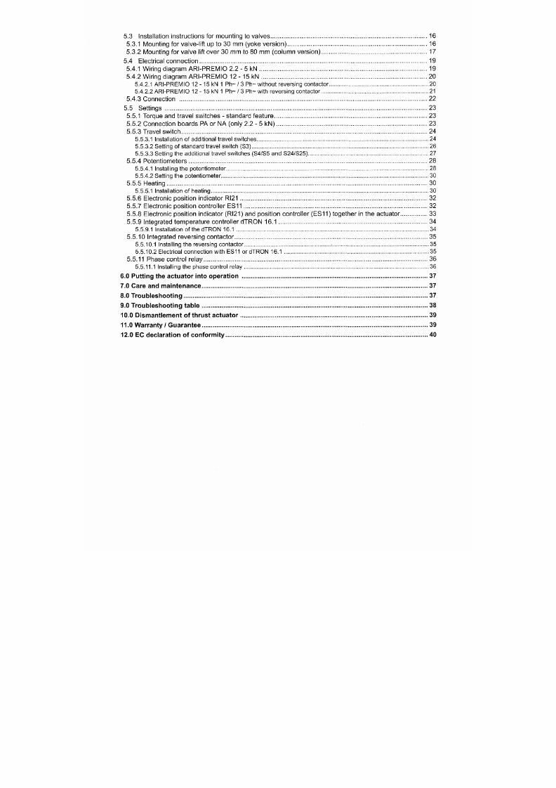
7/18/2019 M14 Thermal Fluid
http://slidepdf.com/reader/full/m14-thermal-fluid 203/486
5.5.3.1 Installation of additional trave l switches 24
5.5.3.2 Setting of standard travel switch (S3) 26
5.5.3.3 Setting the additional travel switches (S4/S5 and S24/S25) 27
5.5 .4 Potent iometers 28
5.5.4.1 Installing the potentiom eter 28
5.5.4.2 Setting the potentiometer 30
5.5.5 Heat ing 30
5.5.5.1 Installation of heating 30
5.5.6 Elect ronic pos i t ion indicator Ri2 1 32
5.5.7 Elect ronic pos i t ion control ler ES11 32
5.5.8 Elect ronic pos i t ion indicator (RI21 ) and pos i t ion control ler (ES11 ) toge ther in the actuator 33
5.5 .9 In tegra ted temp erature cont ro l le r dTR ON 16.1 34
5.5.9.1 Installation of the dTRO N 16.1 34
5.5.10 Integrated reve rs ing con tactor 35
5.5.10.1 Installing the reversing contac tor -. 35
5.5.10.2 Electrical connection with ES11 or dTRO N 16.1 35
5.5.11 Pha se con trol relay 36
5.5.11.1 Installing the phase control relay 36
A R M A T U R E N
Operating and installation instructions
Thrust actuator ARI-PREMIO
1.0 Ge nera l infornnation on op era ting instruc tions
These operating instructions provide information on mounting and maintaining the fittings.
Please contact the supplier or the manufacturer in case of problems which cannot be
solved by reference to the operating instructions.
They are binding on the transport, storage, installation, start-up, operation, maintenance
and repair.
The notes and warnings must be observed and adhered to.
- Handling and all work must be carried out by expert personnel or all activities must be
supervised and chec ked.
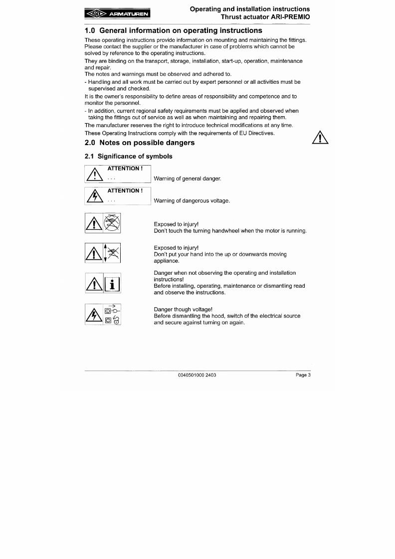
7/18/2019 M14 Thermal Fluid
http://slidepdf.com/reader/full/m14-thermal-fluid 204/486
It is the owner's responsibility to define areas of responsibility and competence and to
monitor the personne l.
- In addition, current regional safety requirements must be applied and observed when
taking the fittings out of service as well as when maintaining and repairing them.
The manufacturer reserves the right to introduce technical modifications at any time.
These Operating Instructions comply with the requirements of EU Directives.
2.0 Notes on poss ible dang ers
2.1 Significance of symbols
Warning of general danger.
A
A R M A T U R E N
Operating and installation instructions
Thrust actuator ARI-PR EM IO
2.2 Explanatory notes on safety information
In these Operating and Installation Instructions dangers, risks and items of safety
information are highlighted to attract special attention.
Information m arked with the above sym bol and
"ATTENTION "
describe practices, a
failure to comply with which can result in serious injury or danger of death for users or third
parties or in material damage to the system or the environment. It is vital to comply with
these practices and to m onitor com pliance.
All other information not specifically emphasised such as transport, installation, operating
and maintenance instructions as well as technical data (in the operating instructions,
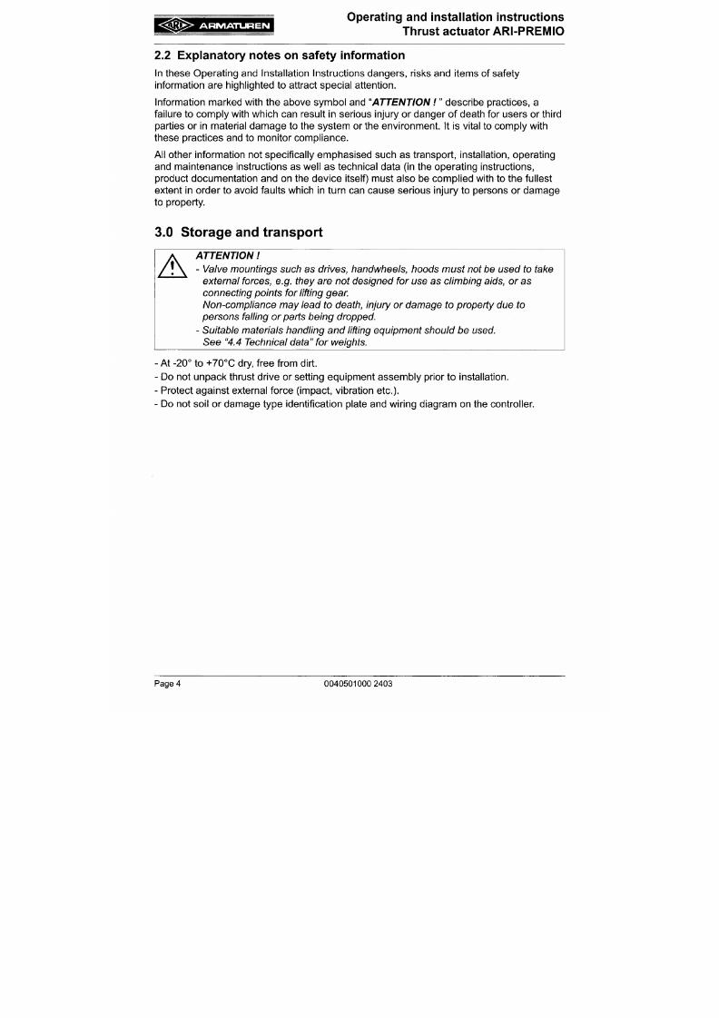
7/18/2019 M14 Thermal Fluid
http://slidepdf.com/reader/full/m14-thermal-fluid 205/486
product documentation and on the device itself) must also be complied with to the fullest
extent in order to avoid faults which in turn can cause serious injury to persons or damage
to property.
3.0 Storage and transport
Ä
ATTENTION
- Valve mountings such as drives, handwheels, i ioods must not be used to tai<e
external forces, e.g. they are not designed for use as climbing
aids,
or as
conne cting points for lifting gear.
Non-compliance m ay lead to death, injury or damage to property due to
persons falling or parts being dropped.
- Suitable materials handling and lifting equipment should be used.
See "4.4 Technical data" for weights.
A R M A T U R E N
Operating and installation instructions
Thrust actuator ARI-PREMIO
4 . 0 D escr i p t i on
4.1 Field of application
ARI-PREMIO linear thrust actuators are employed to actuate control or shut-off valves
requiring a nominal linear stroke distance of up to 80 mm and thrust from 2.2 kN to 15 kN.
The thrust a ctuators are set to the thrust forces specified in the technical da ta. If supplied
with the valve , the lift of the thrust actuator will be set to the stroke distanc e of the valve.
Selection of the proper actuator version in alignment with the corresponding fitting as well
as use of the thrust actuator in accordance with the specified technical data is the
responsibility of the systems engineer.
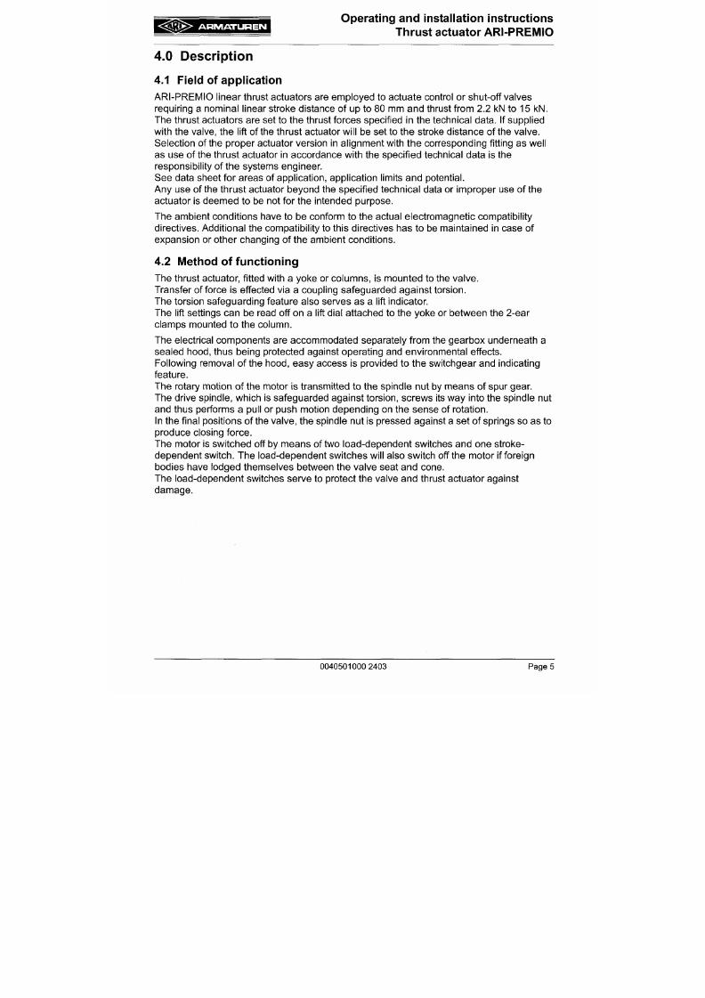
7/18/2019 M14 Thermal Fluid
http://slidepdf.com/reader/full/m14-thermal-fluid 206/486
See data sheet for areas of application, application limits and potential.
Any use of the thrust actuator beyond the specified technical data or improper use of the
actuator is deemed to be not for the intended purpose.
The ambient conditions have to be conform to the actual electromagnetic compatibility
directives. Additional the compatibility to this directives has to be maintained in case of
expansion or other changing of the ambient conditions.
4.2 Method of functioning
The thrust actuator, fitted with a yoke or columns, is mounted to the valve.
Transfer offeree is effected via a coupling safeguarded against torsion.
The torsion safeguarding feature also serves as a lift indicator.
The lift settings can be read off on a lift dial attached to the yoke or betwee n the 2-ear
clamps mounted to the column.
A R M A T U R E N
Operating and installation instructions
Thrust actuator ARl-PREIVIIO
4.3 Diagram
4.3.1 ARl-PRE M IO 2,2 - 5 kN
Yoke Vers ion
Column Vers ion
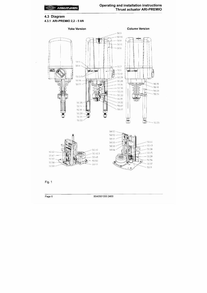
7/18/2019 M14 Thermal Fluid
http://slidepdf.com/reader/full/m14-thermal-fluid 207/486
A R M A T U R E N
Operating and installation instructions
Thrust actuator ARI-PREIVIIO
4.3.2
ARI-PREMIO
12 -1 5 kN
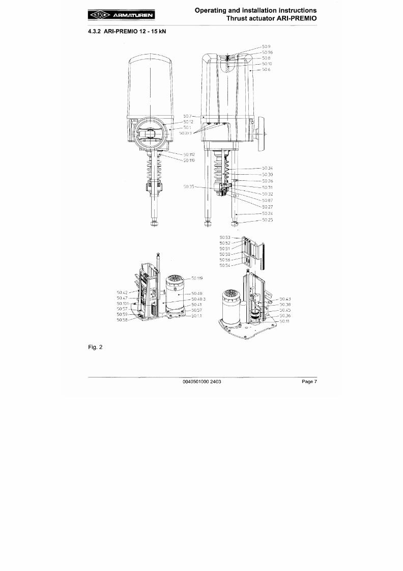
7/18/2019 M14 Thermal Fluid
http://slidepdf.com/reader/full/m14-thermal-fluid 208/486
A R M A T U R E N
Operating and installation instructions
Thrust actuator ARI-PREMIO
4.3.3 Parts list
50.1
50.1.1
50.2
50.3
Designation
Gearbox
Gearbox cover plate
Cable co nduit fitting
2.2-5l<N:
2 x P G 1 1
1 2 - 1 5 k N : 2 X P G 1 3 . 5 / 1 x P G 9
Blanking plate
50.34
50.35
50.36
50.37
50.38
50.39
Designation
Bellow
Grub screw DIN ISO 4766 - M6
Set co llar
Grub screw DIN 913-M3x5
Guide spindle
Hexagon nut DIN EN ISO 4034 - M5
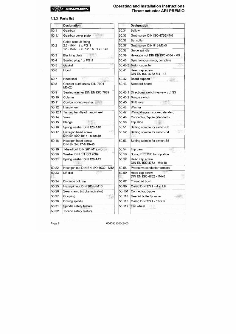
7/18/2019 M14 Thermal Fluid
http://slidepdf.com/reader/full/m14-thermal-fluid 209/486
50.4
50.5
50.6
50.7
50.8
50.9
50.10
50.11
50.12
50.12.1
Sealing plug 1 x PG11
Gasket
Hood
Hood seal
Counter-sunk screw DIN 7991-
M5x20
Sealing washer DIN EN ISO 7089
Column
Conical spring washer
Handwheel
Turning handle of handwheel
50.40
50.40.3
50.41
50.42
50.43
50.43.1
50.43.2
50.45
50.46
50.47
Synchronous motor, complete
Motor capacitor
Head cap screw
DIN EN IS0 47 62-M 4-18
Board support
Standard board
Directional switch (valve - up) S3
Torque switch
Shift lever
Washer
Wiring diagram sticker, standard
A R M A T U R E N
Operating and installation instructions
Thrust actuator ARI-PR EMIO
4.4 Technical data
Type
Thrust force l<N
Strol<e dista nce max. mm
Duty classification in accordance
with DIN VDE 0530
Control speed mm /sec.
Motor voltage
ARI-PREMIO
2,2 5,0
50
S1 -1 0 0 % duty cycle; S4 - 80% duty cycle
1200 c/h
0.25 ' 0.38 ; 0.38
230V - 50Hz / 60Hz *
1,0
12,0 15,0
80
SI -100% ED;
S4-50% ED 1200 c/h
0.79
0.38
230V - 50Hz
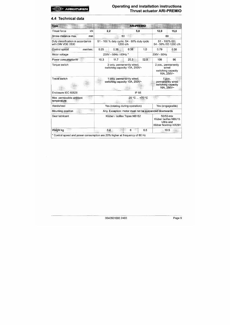
7/18/2019 M14 Thermal Fluid
http://slidepdf.com/reader/full/m14-thermal-fluid 210/486
Power consumptionW
Torque switch
Travel switch
Enclosure IEC 60529
Max. permissible ambient
temperature
Handwheel
10.3 11.7 25.3 52.9
2 only, permanently w ired,
switching capacity 10A, 250V~
1 only, permanently w ired,
switching capacity 10A, 250V~
IP 65
-20 °C ... +70 °C
Yes (rotating during operation)
109 96
2 pes., permanently
wired
switching capacity
16A, 250V~
1 pes.,
permanently wired
switching capacity
16A, 250V-
Yes (engageable)
A R M A T U R E N
Operating and installation instructions
Thrust actuator ARI-PREMIO
Accessories
Type
Thrust force
kN
I
Additional travel switches
ARI-PREMIO
2,2
5,0 12,0
15,0
2 additional travel switches, zero potential.
Switching capacity 10A, 250V
~
Additional travel switches
for
low-voltage
/
electronic system
2 additional travel switches, zero potential, with gold contacts,
fo r
low
breaking capacity a nd
in an
aggressive atmosphere,
switching capacity max.
0.1 A,
4-30V
Potentiometer max.
2
only Ohmage optional: 100, 20 0, 500, 1000, 1000 Ohm ;
1,5
Watt
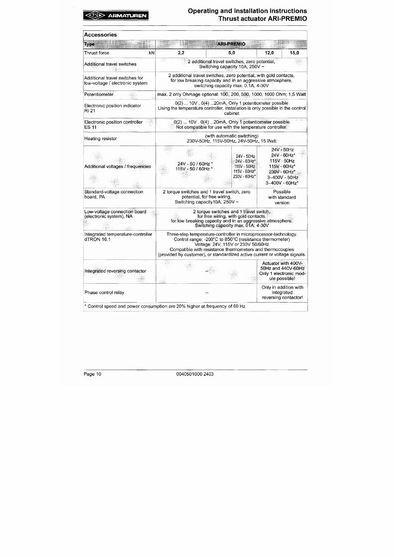
7/18/2019 M14 Thermal Fluid
http://slidepdf.com/reader/full/m14-thermal-fluid 211/486
Electronic position indicator
RI21
0(2)...
10V . 0(4)
...20mA, Only 1 potentiometer possible
Using the temperature controller, installation
is
only possible
in the
control
cabinet
Electronic position controller
ES
11
0(2)...
10V . 0(4)
...20mA, O nly
1
potentiometer possible
Not compatible for use with the temperatu re controller.
Heating resistor
(with automatic switching)
230V-50HZ, 115V-50HZ, 24V-50Hz, 15 Watt
Additional voltages
/
frequencies
24V
- 50 /
60Hz
1 1 5 V - 5 0 / 6 0 H Z '
24V-50HZ
24V -
60Hz*
115V-50Hz
115V-60HZ*
230V-60Hz*
24V
-
50Hz
24V
-
60Hz*
115V-50HZ
115V-60HZ*
230V
-
60Hz*
3~400V - 50Hz
3~400V
-
60Hz*
T I
cp'
CO
o
in
/////////////////////
Clearance required for
removal of hood
. 1 6 5 x 1 5 0
/////////////////////
Clearance required for
removal of hood
/////////////////////
Clearance required for
removal of hood
2 0 0 x 1 7 5
4^
b i
D
I'
(D
3
(A
5"
3
(A
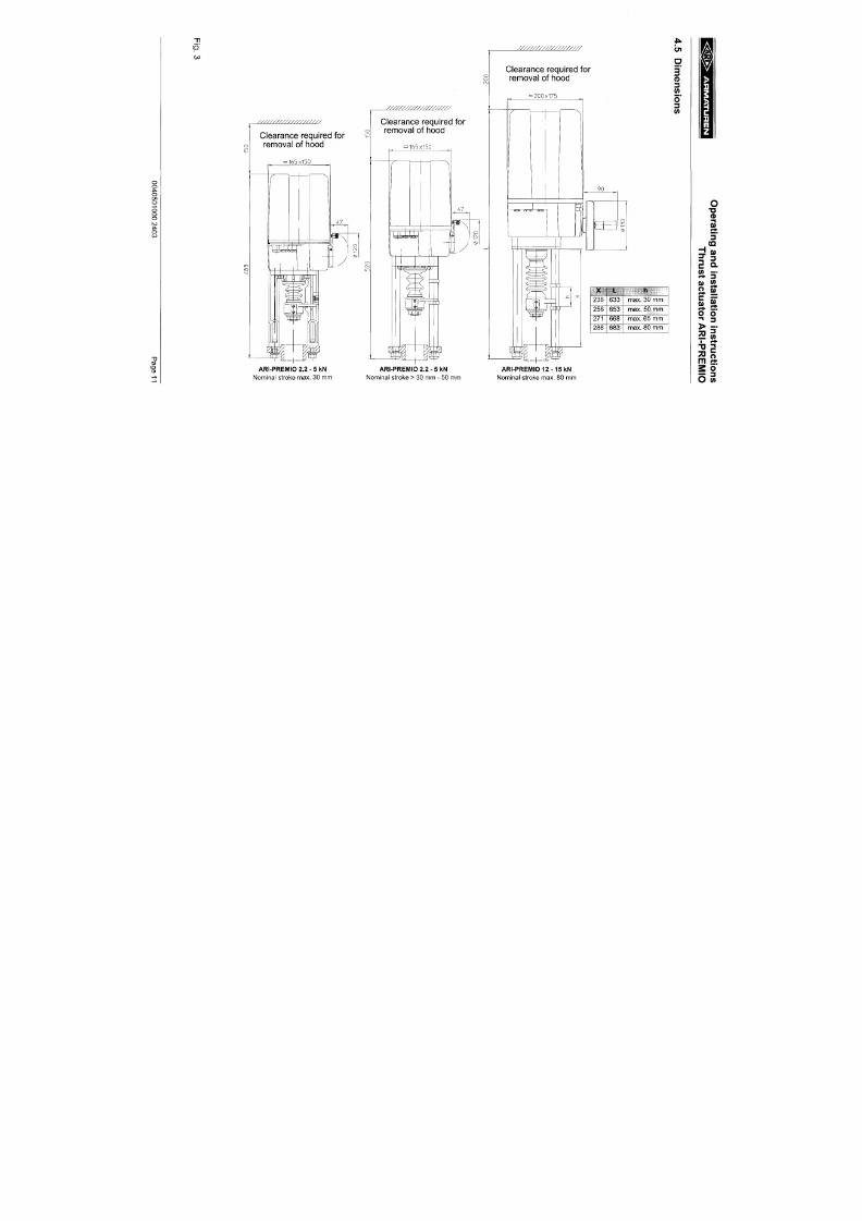
7/18/2019 M14 Thermal Fluid
http://slidepdf.com/reader/full/m14-thermal-fluid 212/486
ARI-PREMIO 2.2 - 5 kN
Nominal stroke max. 30 mm
J^K.
236
256
271
286
..X,
633
653
668
683
h
max.
30 mm
max.
50
mm
max.
65 mm
max.
80
mm
ARI-PREMIO 2.2 - 5 kN
Nominal stroke > 30 mm - 50 mm
ARI -PREMIO 12-15 kN
Nominal stroke max. 80 mm
A R M A T U R E N
Operating and installation instructions
Thrust actuator A RI-P REM IO
5.0 Insta l la t ion
A
ATTENTION
' \ -
W ork on electrical systems or equipment m ust only be carried out by qu alified
electricians or by trained individuals under the guidance and supen/ision of
a
qualified electrician in compliance w ith regional electrical safety requ irements
and regulations.
- Valve mountings such as drives, handwheels, ho ods must n ot be used to take
external forces, e.g. they are not designed for use as climbing aids, or as
conne cting points for lifting gear
Non-compliance m ay lead to death, injury or dam age to property due to
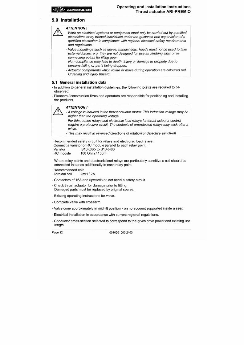
7/18/2019 M14 Thermal Fluid
http://slidepdf.com/reader/full/m14-thermal-fluid 213/486
persons falling or parts being dropped.
- A ctuator comp onents which rotate or move during operation a re coloured red.
Crushing and injury hazard
5.1 General installation data
- In addition to gene ral installation g uidelines, the following points are required to be
observed:
- Planners / construction firms and operators are responsible for positioning and installing
the products.
A
ATTENTION
- A voltage is induce d in the thrust actuator mo tor This induction voltage may be
higher than the operating voltage.
A R M A T U R E N
Operating an d installation instructions
Thrust actuator ARI-PREMIO
- Mains fuse rating max. 6A.
- C ircuit breakers in the plant to cut off the mains supply to the actuator.
- Conformity of technical data on thrust actuator with field conditions.
- Mains voltage in accordance with data specified on rating plate of thrust actuator.
- Thrust actuator complete with yoke or distance columns and coupling parts intended for
mounting to the corresponding valve.
- Ease o f access to installation s ite.
- Adequate clearance space above the thrust actuator for removing the hood
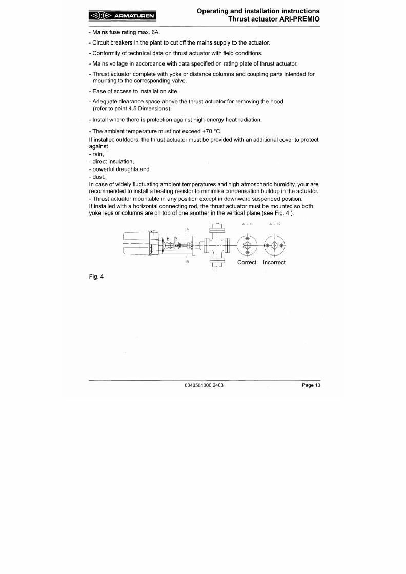
7/18/2019 M14 Thermal Fluid
http://slidepdf.com/reader/full/m14-thermal-fluid 214/486
(refer to point 4.5 Dimensions).
- Install where there is protection against high-energy heat radiation.
- The ambient temperature must not exceed +70 °C.
If installed outdo ors, the thrust actuator must be provided with an additional cover to protect
against
-
rain,
- direct insulation,
- powerful draughts and
- dust.
In case of widely fluctuating am bient temp eratures and high atmospheric humidity, your are
recommended to install a heating resistor to minimise condensation buildup in the actuator.
A R M A T U R E N
Operating and installation instructions
Thrust actuator ARI-PREiVIIO
5.2 iVIanual operation
5.2.1 ARI-PREMIO 2.2 - 5 kN
A
ATTENTION
1
- The handwheel always rotates during motor-driven operation (running
indicator). Never activate manual operation while the motor is running.
Injury hazard
- In the manu al operating m ode pa y careful attention in the final positions tha t the
handwheel is only turned to the point where the torque switch trips (audible
click) as otherwise damage will be caused to the thrust actuator Since the
handwheel always follows during motor-driven operation (running indication),
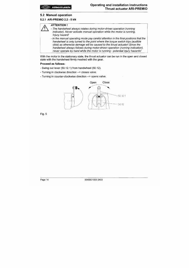
7/18/2019 M14 Thermal Fluid
http://slidepdf.com/reader/full/m14-thermal-fluid 215/486
never operate by h and while the motor is running - potential injury hazards
With the m otor in the stationary state, the thrust actuator can be run in the open and closed
state with the handwheel firmly meshed with the gear.
P roceed as follows:
- Swing out lever (50.12.1) from handwheel (50.12).
- Turning in clockwise direction --> closes valve.
- Turning in counter-clockwise direction - > opens valve.
Open Close
A R M A T U R E N
Operating and installation instructions
Thrust actuator ARI-PREMIO
5.2.2 ARI-PREMIO 12 -15 kN
A
ATTENTION
- D o not attempt to engage manu al operation unti l the motor has stopped.
Switching over w hile the motor is running may dam age the thrust actuator.
- In the manua l operating mode pay careful attention in the final positions that the
handwheel is only turned to the point where the torque switch trips (audible
click) as otherwise damage will be caused to the thrust
actuator
With the motor in the stationary state, the thrust actuator can be run in the open and closed
state with the engagea ble hand whee l.
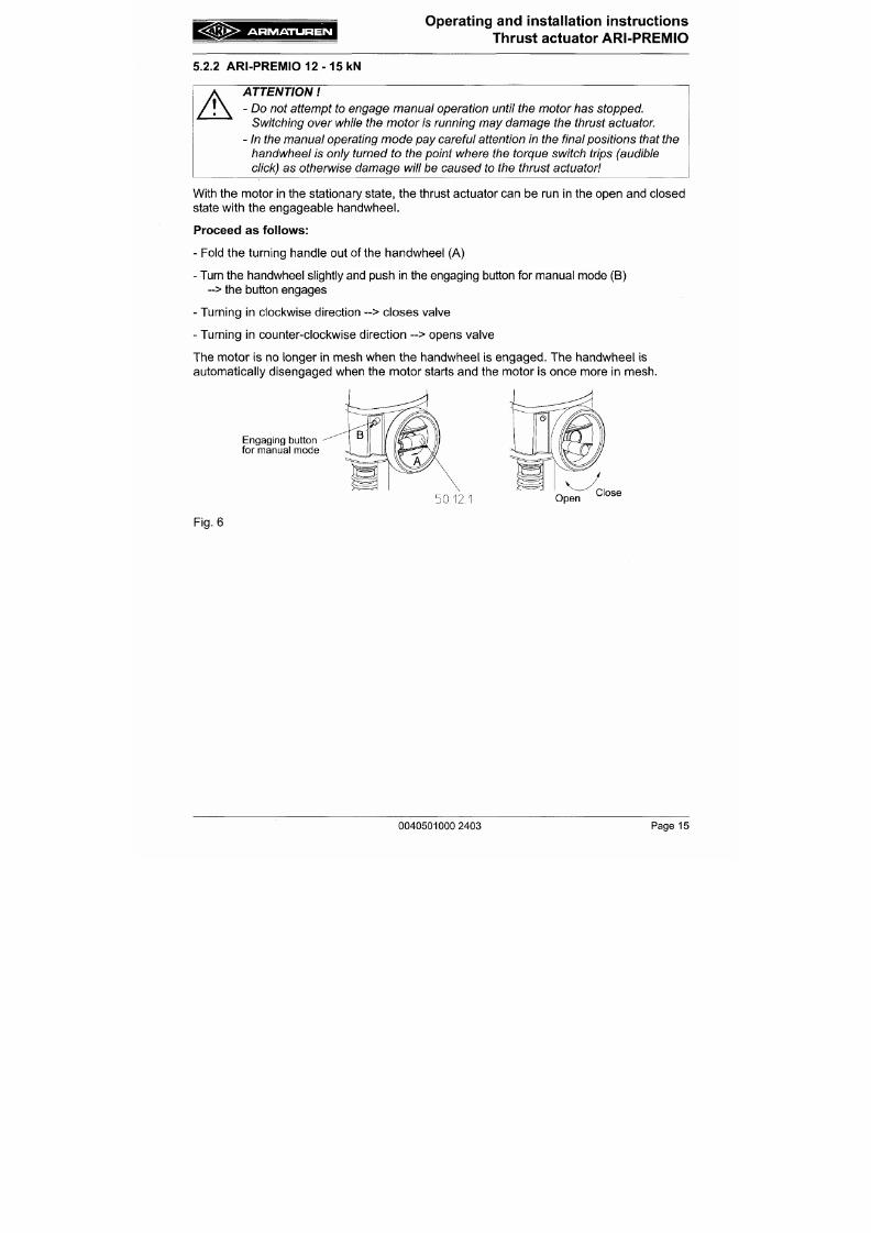
7/18/2019 M14 Thermal Fluid
http://slidepdf.com/reader/full/m14-thermal-fluid 216/486
Proceed as follows:
- Fold the turning handle out of the handwheel (A)
- Turn the handwhee l slightly and push in the engaging button for manua l mode (B)
- > the button engages
- Turning in clockwise direction -> closes valve
- Turning in counter-clockwise direction - > opens valve
The m otor is no longer in mesh wh en the handwheel is engage d. The handwheel is
automatically disengaged when the motor starts and the motor is once more in mesh.
A R M A T U R E N
Operating and installation instructions
Thrust actuator ARI-PREMIO
5 .3 Installation instructions for mounting to valves
5 .3.1 Mou nting for valve-lift up to 30 mm (yok e version)
A B C D E
turn
50.87
50.27
50.12.1
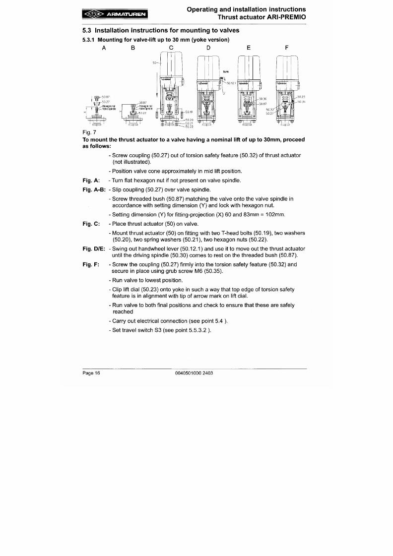
7/18/2019 M14 Thermal Fluid
http://slidepdf.com/reader/full/m14-thermal-fluid 217/486
nut
•Vave spindle
ttf
å s::^Valvespi
Fig. 7
To moun t the thrust actuator to a valve hav ing a nom inal lift of up to 30 m m, proceed
as follow s:
- Screw coupling (50.27) out of torsion safety feature (50.32) of thrust actuator
(not illustrated).
- Pos ition valve cone approximately in mid lift position.
Fig.
A : - Turn flat hexagon nut if not present on valve spindle.
A R M A T U R E N
Operating and installation instructions
Thrust actuator ARI-PR EMIO
5 .3.2 Mounting for valve lift over 30 mm to 80 mm (column version)
A B C D E
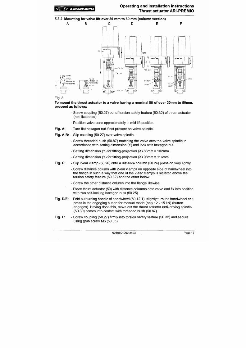
7/18/2019 M14 Thermal Fluid
http://slidepdf.com/reader/full/m14-thermal-fluid 218/486
5 0 . 8 7
5 0 . 2 7
lexagon nut
^aive spind le
Fig. 8
To mount the thrust actuator to a valve having a nom inal lift of over 30mm to 5 0mm ,
proceed as follows:
- Screw coupling (50.27) out of torsion safety feature (50.32) of thrust actuator
(not illustrated).
A R M A T U R E N
Operating and installation instructions
4B .^^-iiu^r,ii-iii-i> i Thrust actuator ARI-PREIVIIO
Move the valve to the lowest position.
Press 2-ear clamps (50.26) into position according to the stroke so they cannot
slip,
with the bottom clamp in the lowest valve position located directly below
torsion safety feature (50.32) and the top clamp in the highest valve position
located directly above the torsion safety feature.
M ove the valve to both travel positions and ch eck that it reaches them reliably.
Fold turning handle of handwheel (50.12.1) back in.
Make the electrical connection (see point "5.4 Electrical connection"). The
engaging button for manual mode (only 12-15 kN) disengages when the
motor starts up.

7/18/2019 M14 Thermal Fluid
http://slidepdf.com/reader/full/m14-thermal-fluid 219/486
Set standard trave l switch S3 (see point 5.5.3.2 ).
F
g
9
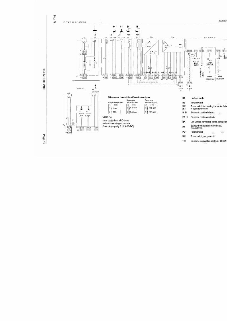
7/18/2019 M14 Thermal Fluid
http://slidepdf.com/reader/full/m14-thermal-fluid 220/486
f
3^
Rä
l
E
i
I
I
I«
a
^é
c
(
D
C
L
O
C
C
<
—
^
a
£
n
7i
-
O
)
<<
—
i^
•
C
Oo
^
-
^
^
0
0
2
F
g
1
P
2
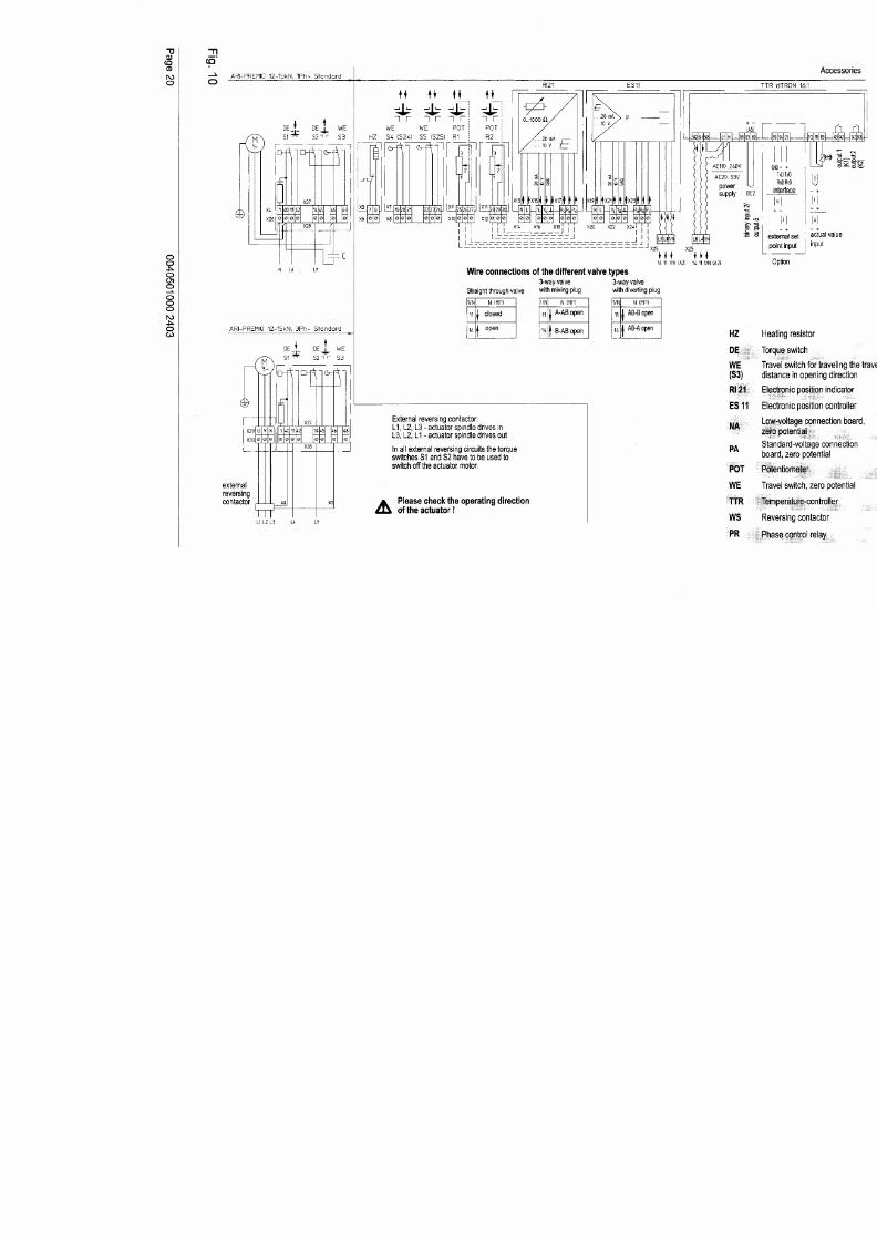
7/18/2019 M14 Thermal Fluid
http://slidepdf.com/reader/full/m14-thermal-fluid 221/486
I
M
U
X
a
:
s
i
£
i
I
8
^
i
f
T
5z
^
i
S
m
<
s
n<
^^
2
-
<<
<d
i
i
1
?
1
^
-I
f1
a
c
—
T
0
^
^
é
Ü
-
L
'
M
J
r
^
X
h
n
i
0
2
F
g
1
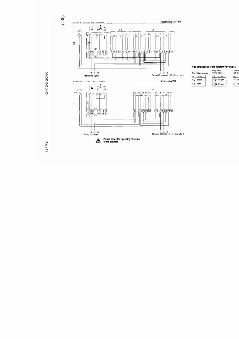
7/18/2019 M14 Thermal Fluid
http://slidepdf.com/reader/full/m14-thermal-fluid 222/486
2
^
o
f
c
s
,
^
D
H
Æ
n
U
e
I
T
CI
Z
Æ
X
L
C
Q
o
H
d
-
n
^
E
s
^
0
0
2
A R M A T U R E N
Operating and installation instructions
Thrust actuator ARI-PREMIO
5.4.3 Connection
A
ATTENTION
- Work on electrical systems or equipment must only be carried out by qualified
electricians or by trained individuals under the guidance and supervision of a
qualified electrician in compliance with regional electrical requirement and
regulations.
- Wh en connecting the thrust actuator the supply line m ust be disconnected from
the ma ins (no t live) during connection work. It must be imposs ible to switch the
power on unintentionally while the mains are disconnected in this way. Failure
to comply may result in death, serious injury or substantial damage to property.
7/18/2019 M14 Thermal Fluid
http://slidepdf.com/reader/full/m14-thermal-fluid 223/486
To connect the thrust actuator up to the electrical power supply, proceed as follows:
- Run the thrust actuator a few mm out of the lower final position applying the manual mode.
- Loosen countersunk screw in hood, carefully remove hood in upward direction.
- Screw out one of the two cable inlets and re-assemble in the same w ay without the
supplied blank flange.
- Insert the conn ection line through this cable inlet until sufficient co nductor length is
available up to the corresponding terminals; then tighten the cable connection until the
connecting cable is clamped in place inside it.
- Strip connecting cable approx. 1-1.5 cm above cable inlet.
- Strip the individual conductors approx. 5mm away from the end and fit with conductor end
A R M A T U R E N
Operating and installation instructions
Thrust actuator ARI-PREMIO
5.5 Settings
A
A
ATTENTION
- The thrust actuator may only be operated for a short time without the hood for
unavo idable setting operations to the potentiom eters, travel switches and the
electrical options. W hile these operations are in progress, the thrust actuator
has hazardous, live, uninsulated parts exposed as well as moving and rotating
parts.
- Improper execution of
the
setting operations or lack of
care
may cause d eath,
grievous bodily injury or substantial property damage.
- Operation of the thrust actuator without the hood for any purpose other than
that described above is strictly prohibited.
7/18/2019 M14 Thermal Fluid
http://slidepdf.com/reader/full/m14-thermal-fluid 224/486
5 .5.1 Torque and travel switches - standard feature
As standard, thrust actuators are equipped with a load-dependent travel switch for the
closing direction (S1), a load-dependent travel switch for the opening direction (S2) and a
stroke-dependent travel switch for the opening direction (S3).
The load-dependent travel switches
(S1,
S 2) switch off the motor as soon as the factory-set
thrust force is attained.
A
ATTENTION
- The settings of the load-dependent travel switches must on no account
whatsoever be chan ged
A R M A T U R E N
Operating and installation instructions
Thrust actuator ARI-P REM IO
The optional boards may only be installed at the factory due to the switching points of the
load-dependent switches having to be reset following installation of these boards
A
ATTENTION
" '^ - W hen using optional boards PA o r
N A ,
it mus t be warranted - due to the
operator's individual circuitry- that, when switching the load-dependent travel
switches
S11/21,
S12/S22 and S13/S23 the motor of
the
thrust actuator comes
to a standstill without
delay.
This function is not provided for on the optional boards PA and NA in the
supplied state
5.5.3 Travel switch
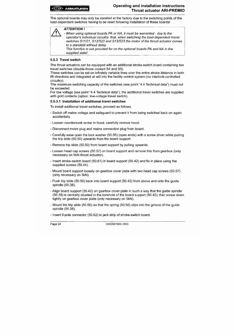
7/18/2019 M14 Thermal Fluid
http://slidepdf.com/reader/full/m14-thermal-fluid 225/486
The thrust actuators can be equipped with an additional stroke-switch board containing two
travel switches (double-throw contact S4 and S5).
These switches can be set on infinitely variable lines over the entire stroke distance in both
lift directions and integrated at w ill into the facility control sys tem (no interlock-controlled
circuitry).
The maximum switching capacity of the switches (see point "4.4 Technical data") must not
be exceeded.
For low voltage (see point "4.4 Technical data"), the additional travel switches are supplied
with gold contacts (option: low-voltage travel switch).
5 .5.3.1 Installation of additional travel switches
To install additional travel switche s, proceed as follows .
- Switch off mains voltage and safeguard to prevent it from being switched back on again
A R M A T U R E N
Operating and installation instructions
Thrust actuator ARI-P REM IO
Proceed to strip the connecting cable that has been led in through the cable inlet and
fastened,
and connect the individual conductors to the terminal strip in accordance with
the desired circuitry and the wiring diagram.
Set switch points on travel switches in accordance with section 6.3.2. Setting the travel
switches
Insert motor connection plug in jack strip (50.43.4) provided for the purpose.
Insert mains connection plug in jack strip (50.43.3) provided for the purpose.
Carefully place hood onto gearbox and mount firmly on thrust actuator with rubber gasket
and countersunk screw.
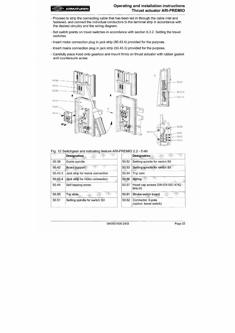
7/18/2019 M14 Thermal Fluid
http://slidepdf.com/reader/full/m14-thermal-fluid 226/486
50X4
50.62
A R M A T U R E N
Operating and installation instructions
Thrust actuator ARI-PREMIO
5 .5.3.2 Setting of standard travel switch (S3)
On delivery of the thrust actuator, the standard travel switch (S3) is already set to the
existing valve-lift and the setting spindle for the travel switch S3 (50.51) is sealed with
screw glyptal.
This setting needs no changing for nornnal operation.
If reinstalling the thrust actuator on a straight-way valve, the travel switch S3 needs to be
set as follows:
- M ove valve out of the lowes t position so as to run valve-lift to up position.
- Using a screw driver, proc eed to turn setting spindle for switch S3 (50.51) until the trip cann
(50.54) arriving from below trips the switch (audible click).
7/18/2019 M14 Thermal Fluid
http://slidepdf.com/reader/full/m14-thermal-fluid 227/486
- Run thrust actuator briefly in closing direction and then in opening direction once more,
checking to see whether the thrust actuator is switched off at the desired point (nominal
lift).
- If need be, correct the setting as described.
If reinstalling the thrust actuator on a three-way valve, the travel switch S3 needs to be set
as follows:
- Run valve in both final positions and check in each final position whether the valve
switches off via the load-dependent switch.
- Carry out a check in the top final position the see whether, after switching off the thrust
actuator, the trip cam (50.54) of the travel switch S3 is situated below switch S3 and has
not tripped the latter. If the trip cam (50.54) is situated above the travel sw itch S3 or trips
A R M A T U R E N
Operating and installation instructions
Thrust actuator ARI-P REM IO
5.5 .3.3 Setting the additional travel switches (S4/S5 and S24 /S25 )
The two a dditional travel switches c an be freely set in both lift directions for indicating
certain valve positions.
To do this, proceed as follows :
- Run valve to desired position due to be indicated by the corresponding switch.
- Proceed to turn the setting spindle belonging to the appurtenant switch until the switch is
tripped (audible click).
- Run thrust actuator briefly in both directions, checking and, if need be, correcting the
setting.
The actuating feature on the travel switches is designed in such a way that both travel
7/18/2019 M14 Thermal Fluid
http://slidepdf.com/reader/full/m14-thermal-fluid 228/486
switches can be overrun in both directions.
Standard design:
Fo rthat reaso n, care should be taken on additional travel switches to see that the actuating
state of the sw itches remains active on ly for a short time while the thrust actua tor co ntinues
to run and that switching back takes place afterwards.
The ac tuating state of the travel switches remains in force over a lift of 4 mm .
Special de sign:
At additional travel switches with extended switch levers, the actuating state of the travel
switches remains in force over a lift of 49 mm.
A R M A T U R E N
Operating and installation instructions
Thrust actuator A RI-PRE MIO
5.5.4 Potentiometers
The potentiometers are used for electrical position acknowledgement on the facility control
system or for the options - electronic position controller ES11 or electronic position indicator
RI21
A maximum of 2 potentiometers can be installed (= 1 double potentiometer).
The potentiometers can be supplied with different resistance values (see point „4.4
Technical data").
For the electronic position controller ES11 and the electronic position indicator RI21 use
must be made solely of 1000 ohm potentiometers.
Conversion of the relevant valve-lift to the potentiometer angle of rotation is effected by
means of transmission determined in respect of each valve-lift between the toothed rack on
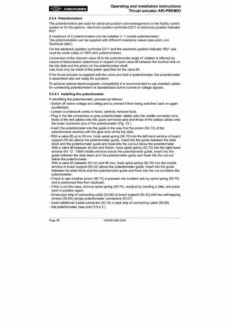
7/18/2019 M14 Thermal Fluid
http://slidepdf.com/reader/full/m14-thermal-fluid 229/486
the trip slide and the pinion on the potentiometer shaft.
Use must only be made of the pinion specified for the valve-lift.
If the thrust actuator is supplied with the valve and built-in potentiome ter, the potentiome ter
is assembled and set ready for operation.
To achieve optimal electromagnetic compatibility it is recommended to use shielded cables
for connecting potentiometers or standardized active current or voltage signals.
5 .5.4.1 Installing the potentiometer
If retrofitting the potentiometer, proceed as follows:
- Switch off mains voltage and safeguard to prevent it from being switched back on again
accidentally.
A R M A T U R E N
Operating and installation instructions
Thrust actuator ARI-PREMIO
Place hood carefully onto thrust actuator and fasten it on the actuator with rubber gasket
and countersunk screw.
red
grey
yellow
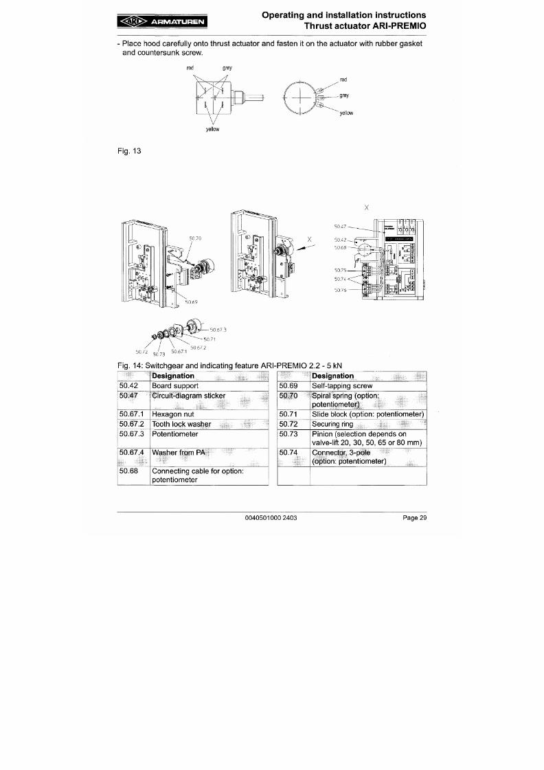
7/18/2019 M14 Thermal Fluid
http://slidepdf.com/reader/full/m14-thermal-fluid 230/486
Fig. 13
X
50.47
A R M A T U R E N
Operating and installation instructions
Thrust actuator ARI-PREMIO
5.5.4.2 Setting the potentiometer
To set the potentiometer, proceed as follows:
- Move thrust actuator to closing position.
- Switch off mains voltage and safeguard to prevent it from being switched back on again
accidentally.
- Turn potentiometer shaft in counter-clockwise direction until reaching the travel stop.
This places the potentiometer in the initial position (approx. 0 ohm).
- For checking purposes, the resistance of the potentiometer needs to be measured using
an ohmmeter.
- Measure resistance on potentiometer 1 between terminals 25 and 26 .
- M easure resistance on potentiometer 2 between terminals 28 and 29 .
7/18/2019 M14 Thermal Fluid
http://slidepdf.com/reader/full/m14-thermal-fluid 231/486
- In this position of the actuator, the measured value should be approx. 0 ohm.
- Run thrust actuator to upper final position and read off corresponding resistance value on
ohmmeter.
- The resistance values thus measured need to be taken into account for the settings to the
facility control system .
5.5.5 Heating
A heating resistor can be fitted as a means of protection against the formation of
condensation water in cases involving widely varying ambient temperatures and high
atmospheric humidity (outdoor use). The heating resistor is self-regulating so that a
continuous supply of current merely needs to be connected up.
A R M A T U R E N
Operating and installation instructions
Thrust actuator ARI-PREMIO
Mounting thread M3
for heating resistor
Mounting th read M3^
for
jacl<
strip
Mounting thread M3
for thermal circuit breal<er
Mounting thread M4
for options ES 11 and RI21
50.83.6
Fig.
15: Heating installation ARI-PREMIO
2.2-15
kN
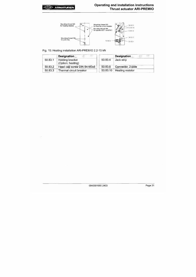
7/18/2019 M14 Thermal Fluid
http://slidepdf.com/reader/full/m14-thermal-fluid 232/486
50.83.1
50.83.2
50.83.3
Designation
Holding bracket
(Option: heating)
Head cap screw DIN 84-M3x8
Thermal circuit breaker
50.83.4
50.83.6
50.83.10
Designation
Jack strip
Connector, 2-pole
Heating resistor
A R M A T U R E N
Operating and installation instructions
Thrust actuator ARI-PREMIO
5 .5.6 Electronic position indicator RI21
The electronic position indicator RI21 converts the resistance of the 1000 ohm
potentiometer corresponding to the lift into an optional output control signal 0 (2) ...10V DC
or 0 (4) ...20mA DC. For installing and setting the electronic po sition indicator RI21 the
operating instructions applicable to this unit must be observed in the appropriate valid
version. The corresponding operating instructions are supplied with each unit.
5 .5.7 Electronic position controller ES11
The electron ic position controller ES 11 converts co ntinuous input control signals 0 (2)
...10V DC or 0 (4) ...20mA into a 3-point output signal for the m otor, In which case
interrogation of the valve position takes place via a 1000 ohm potentiometer. For installing
and setting the e lectronic position controller ES11 the operating instructions applicable to
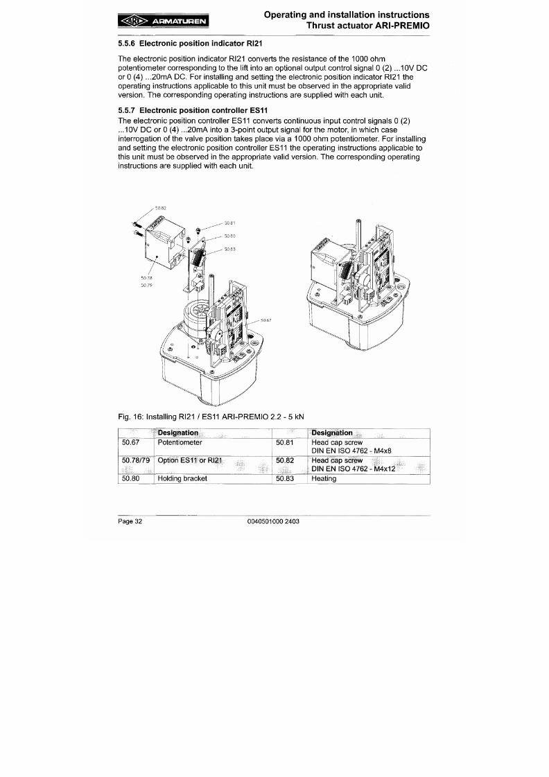
7/18/2019 M14 Thermal Fluid
http://slidepdf.com/reader/full/m14-thermal-fluid 233/486
this unit must be observed in the appropriate valid version. The corresponding operating
instructions are supplied with each unit.
• 50,82
A R M A T U R E N
Operating and installation instructions
Thrust actuator ARI-PREMIO
5 .5.8 Electronic position indicator (RI21) and position controller (ES11) toge ther in
the actuator
Except or the 5 kN , 12 kN and 15 kN type in 24V ve rsion , the e lectronic position indicator
RI21 and the electronic position controller
E S 1 1
can be build-in together in the A R I-
PREMIO.
It must be used a double potentiometer with 1000/1000 Ohm.
To install the R I21 and ES11 proceed a s follows:
- Switch off mains voltage and safeguard to prevent it from being switched back on again
accidentally.
- Loosen counter-sunk screw in hood, carefully remove hood.
- Mount RI21 and ES11 with mounting kit according to Fig. 17 .
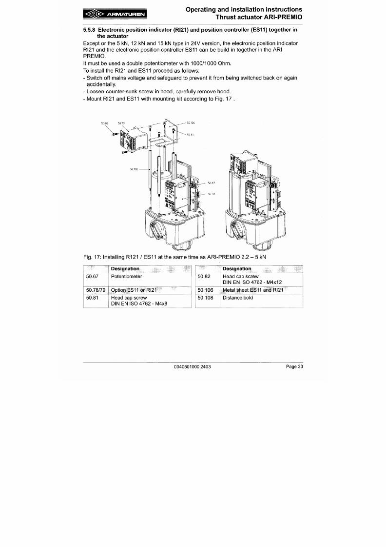
7/18/2019 M14 Thermal Fluid
http://slidepdf.com/reader/full/m14-thermal-fluid 234/486
5 0 8 2
5 0 1 0 6
5 0 6 7
A R M A T U R E N
Operating an d installation instructions
Thrust actuator ARI-PREMIO
5 .5.9 Integrated tempe rature controller dTRON 16.1
The integrated temperature controller controls temperatures, which are measured by input-
connected tem perature sensors, to a m anual given setpoint by m eans of a three-step
output connected with the actuator.
5.5.9.1 Installation of the dTR ON 16.1
The dTR ON 16.1 can be mou nted in the ARI-PRE M IO as a complete unit with a mou nting
kit.
It cannot be combined w ith ES1 1.
To install the dTRO N 16.1 proceed as follows :
In addition to "5.4.3 Connection", the electrical connection of the dTRON 16.1 has to be
done in the following way:
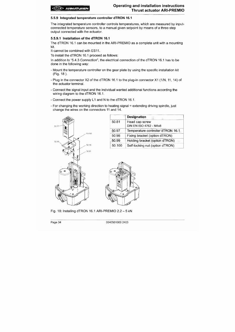
7/18/2019 M14 Thermal Fluid
http://slidepdf.com/reader/full/m14-thermal-fluid 235/486
- Mount the temperature controller on the gear plate by using the specific installation kit
(Fig.
18) .
- Plug in the connector X2 of the dTRON 16.1 to the plug-in connector
X1
(1/N, 1 1, 14) of
the actuator terminal.
- Connect the signal input and the individual wanted additional functions according the
wiring diagram to the dTRON 16 .1.
- Connect the power supply L I and N to the dTRO N 16 .1.
- For changing the working direction to heating signal = extending driving spindle, just
change the wires on the connectors 11 and 14.
A R M A T U R E N
Operating and installation instructions
Thru st actuator ARI-P REIVIIO
5.5.10 Integrated reversing contactor
The integrated reversing contactor is actuated using a 3-step input signal.
The reversing contactor swa ps over phases
L1,
L2 and L3 to achieve the desired direction
of rotation of the three-phase motor.
5 .5.10.1 Installing the reversing contactor
The reversing contactor can be mounted in the ARI-PR EM IO as a complete unit using a
mounting kit.
The reversing contactor can only be combined with one of the ES11, RI21 or tempe rature
controller options. It is also possible to install the heating and the phase control relay.
Proceed as follows to install the reversing contactor:
Switch off the mains voltage and take measures to prevent it being switched back on
inadvertently.
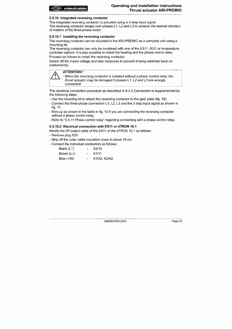
7/18/2019 M14 Thermal Fluid
http://slidepdf.com/reader/full/m14-thermal-fluid 236/486
A
ATTENTION
- When the reversing contactor is installed without a phase control
relay,
the
thrust actuator may be dam aged if phases L1, L2 and L3 are wrongly
connected
The electrical connection procedure as described in 6.4.3 Connection is supplemented by
the following steps:
- Use the mounting kit to attach the reversing contactor to the gear plate (fig. 19).
- Con nect the three-phase conn ection L I , L2, L3 and the 3-step input signal as show n in
fig. 11.
- Wire up as shown in the table in fig. 10 if you are connecting the reversing contactor
A R M A T U R E N
Operating and installation instructions
Thrust actuator ARI-PR EM IO
5 .5.11 P hase control relay
The phase control relay monitors phases L1, L2 and L3 in the mains input supply. The
reversing contactor is only activated by the phase con trol relay providing phases L1, L2 and
L3 are connected correctly. This protects the thrust actuator.
5 .5.11.1 Installing the phas e control relay
The phase control relay is installed in the ARI-PREMIO next to the reversing contactor. It is
only possible to use the phase control relay in conjunction with the reversing contactor. It
cannot be combined with the dTR ON 16.1 temperature controller in the actuator.
Proceed as follows to install the phase control relay:
Switch off the mains voltage and take measures to prevent it being switched back on
inadvertently.
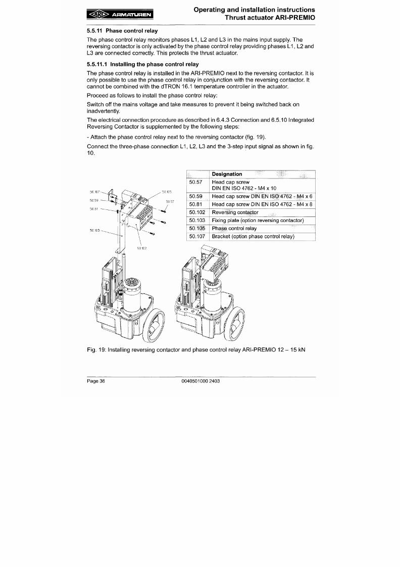
7/18/2019 M14 Thermal Fluid
http://slidepdf.com/reader/full/m14-thermal-fluid 237/486
The electrical connection procedure as described in 6.4.3 Connection and 6.5.10 Integrated
Reversing C ontactor is supplemented by the following steps:
- Attach the phase control relay next to the reversing contactor
(fig.
19).
Conne ct the three-phase connection L I , L2, L3 and the 3-step input signal as shown in fig.
10.
50.105
50.57
Designation
Head cap screw
DIN EN ISO 47 62 -M 4x 10
A R M A T U R E N
Operating and installation instructions
Thrust actuator ARI-PREMIO
6.0 P utt ing the actuato r into operat ion
A
ATTENTION
- Actuator componen ts which rotate or move d uring ope ration are coloured red.
Crushing or injury hazard
Before putting a new plant into operation o r restarting a plant after repairs or
modification, always make sure
that:
- all works has been completed
- Regional safety instructions must be observed as a matter of policy.
- hood of thrust actuator assembled.
W hen placing into service proceed as follows:
- Using the handwheel, run the thrust actuator to approximately mid lift position.
7/18/2019 M14 Thermal Fluid
http://slidepdf.com/reader/full/m14-thermal-fluid 238/486
- Apply brief pulses to the thrust actuator for each direction of movement and check
whether the directions of movement correspond to those desired. If this is not the case,
the pulse lines governing the opening and closing action must be exchanged on the thrust
actuator.
- Run thrust actuator to the final position in each direction of movement and check whether
it switches off automatically and whether all externally moving parts are able to move
freely.
- If failing to function properly, check all installation and setting w ork p reviously carried out,
correcting if necessary, and afterwards place into service once again.
7.0 Care and m aintenanc e
The thrust actuator requires very little maintenance. Accordingly maintenance in specified
A R M A T U R E N
Operating and installation instructions
Thrust actuator ARI-PREIVIIO
9 . 0 T r oub l eshoot i ng tab l e
A
A
ATTENTION I
- read point 10.0 a nd
11.0
prior to disman tling and repair work
- read point 6.0 be fore restarting the
plant
Fault
Thrust actuator fails to move
Possible Causes
Power failure
Fuse has blown
Thrust actuator not properly
connected
Remedy
Ascertain and eliminate cause
Replace fuse
Rectify connection on thrust
actuator in accordance with wiring
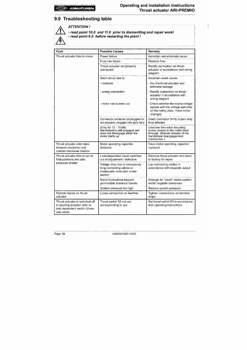
7/18/2019 M14 Thermal Fluid
http://slidepdf.com/reader/full/m14-thermal-fluid 239/486
Short circuit due to:
- moisture
- wrong connection
- motor has burned out
Connector contacts not plugg ed in/
diagram
Ascertain exact cause,
- Dry the thrust actuator and
eliminate leakage
- Rectify connection on thrust
actuator in accordance with
wiring diagram
- Check whether the m ains voltage
agrees with the voltage specified
on the rating plate. Have motor
changed.
Insert connector firmly in jack strip
A R M A T U R E N
Operating and installation instructions
^Bi^^^-i.iiirinn.i-iri Thrust actuator ARI-PREMIO
10.0 Dism antlem en t of thru st actua tor
A
A
A
ATTENTION
- The supply line for connecting up the thrust actuator must be in the dead state
i.e. disconnected while dismantlement work is being carried
out.
After being
disconnected, the mains power must be prevented from being switched back
on again accidentally.
- The system must be run down (depressurised state) as the valve cone is not
held without the thrust actuator and wou ld thus be conducted by the system
pressure.
- Valve plug approximately in mid lift position - on no account supported inside a
seat
To disma ntle the thrust actuator proce ed as follows:
7/18/2019 M14 Thermal Fluid
http://slidepdf.com/reader/full/m14-thermal-fluid 240/486
- Loosen counter-sunk screw in hoo d, carefully rem ove hood.
- Disconnect all cables led into thrust actuator from outside and remove from thrust
actuator.
- Place hood on carefully from above and fix in place with counter-sunk screw and rubber
gasket.
- Loosen grub screw inside torsion safety feature; screw coupling out of torsion safety
feature.
- Loosen clamping bolts connecting the thrust actuator to the fitting.
- Remove thrust actuator from valve.
11.0 Warranty / Guarantee
The extent and period of warranty cover are specified in the "Standard Terms and
A R M A T U R E N
Operating and installation instructions
Thrust actuator ARI-PRE MIO
12.0 EC declaration of conformity
EC declaration of conformity
as defined by
Directive about electromagnetic compatibility 89/336/EEC and the
EG-Low voltage directive 73/23/EEC
Declaration of the manufacturer
as defined by
the M achinery Directive 98/37/EC
Herewith we declare,
7/18/2019 M14 Thermal Fluid
http://slidepdf.com/reader/full/m14-thermal-fluid 241/486
ARI-Armaturen A lbert Richter GmbH & Co. KG,
M ergeiheide 56-60 , 33756 Schloß Holte-Stukenbrock
that the supplied model of
electric thrust actuator AR I-PREM IO
In the delivered version complies with the following regulations:
- Directive about electromagnetic compatibility 89/336/EEC
(amended by 92/31/EEC and 93/68/EEC)
Applied harm onized standards:
Data sheet
Pressure switches and the rm os tats , type KPS
Description
_ .^-- ,^
- n H S ^ ^
)
€ f |
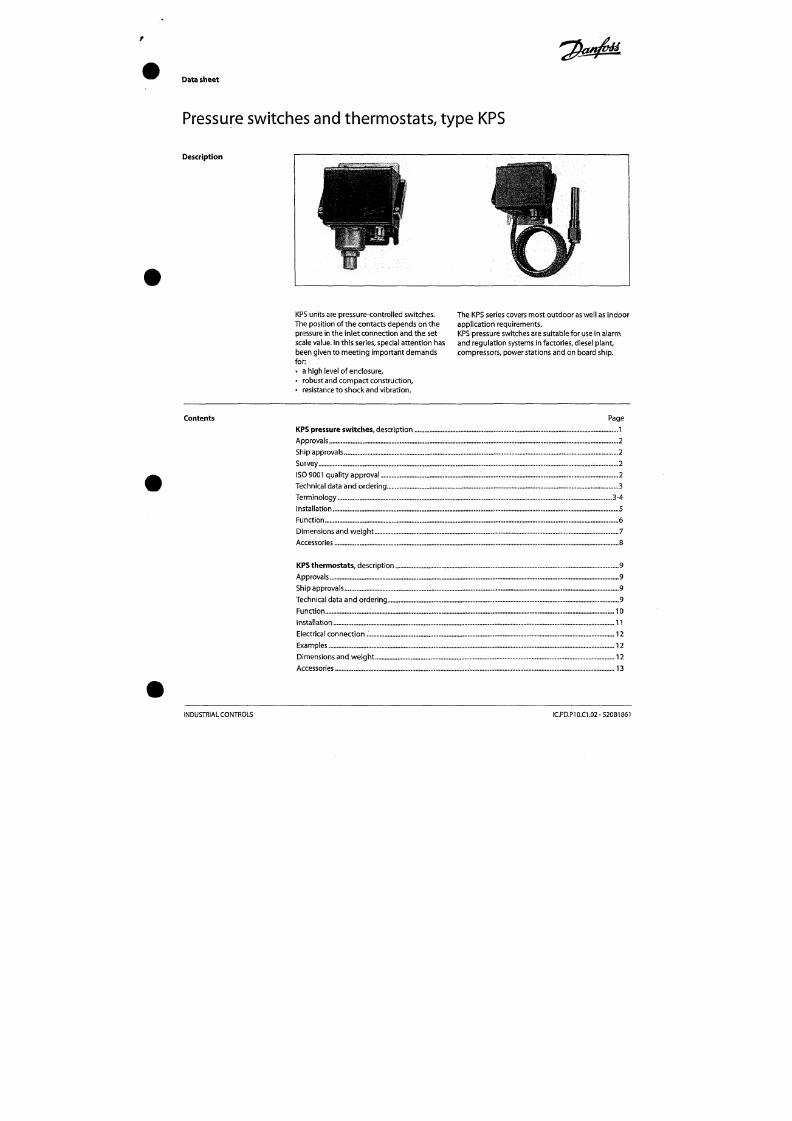
7/18/2019 M14 Thermal Fluid
http://slidepdf.com/reader/full/m14-thermal-fluid 242/486
W
¥
•ß.
, ^ ä ^ f c
mk
f
'
^f\M
U
PS units are press ure-controlled switches.
The position of the contacts depends on the
pressure in the I nlet con nection an d the set
scale value. In this series, special attention has
been given to m eeting im portant dem ands
for:
• a high level of enclosure,
• robust and compact construction,
The KPS series covers mo st o utdo or as well as indoor
application requirements.
KPS pressure switches are suitable for use in alarm
and re gula tion systems in factories, diesel plant,
compressors, power stations and on board ship.
Data sheet
Pressure switches an d therm ostats, ty pe KPS
Approvals
Ship approvals
EN 60 947-4-1
EN 60 947-5-1
American Bureau of Shipping
Lloyds Register of
Shipping,
UK
Germanischer Lloyd , Germany
Bureau Veritas, France
Includes thermostats with fixed sensor
and pressure controls with armoured
capillary tube.
Reglstro Itallano Navale, Italy
Unde rwriters Laboratories Inc., USA
CCC, China Compulsory Certificate
RMRS, M aritim e Register of Ship ping, Russia
Nippon KaijI
Kyokal,
Japan
CCS, China Classification Society
Survey
Type KPS pressure switches
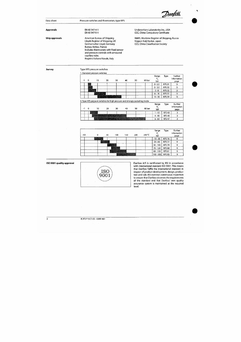
7/18/2019 M14 Thermal Fluid
http://slidepdf.com/reader/full/m14-thermal-fluid 243/486
1. Standard pressure switches
-1 0 10 20
30 40 50
60 bar
Range
P
e
bar
0-2 .5
0-3 .5
0 - 8
6 - 1 8
10-35
Type
KPS
3 1
KPS
33
KPS
35
KPS 37
KPS 39
Further
informat ion
page
3
3
3
3
3
2. Type KPS pressure switches for high pressure and strongly pulsating media
-1 0 10 20
30 40
50
60 bar
Range
P.
bar
1-10
4 - 4 0
Type
KPS 43
KPS 45
Further
informat ion
page
3
3
Data sheet
Pressure switches and th ermo stats, typ e KPS
Technical data and or dering
When ordering, please state
type and code number
1.
Pressure switches
7-
KPS
31,33
Sett ing range
P
e
[bar]
0-2.5
0-2.5
0-3.5
0-3.5
0 - 8
0 - 8
0 - 8
6 - 1 8
6 - 1 8
Adjus table/
fixed
differetial
[bar]
0.1
0.1
0.2
0.2
0.4-1.5
0.4-1.5
0.4
0.85 - 2.5
0.85 - 2.5
Permissible
operat ing
pressure P
[bar]
6
6
10
10
12
12
12
22
22
Max. test
pressure
[bar]
6
6
10
10
12
12
12
27
27
Pressure
connect ion
G 1/4
G
3/8 A
G 1/4
G 3/8 A
G l / 4
G 3 /8 A
G l / 4
G l / 4
G 3 /8 A
Code no.
060-311066
060-310966
060-310466
060-310366
060-310566
060-310066
060-310866
060-310666
060-310166
Type
KPS
31
KPS
31
KPS 33
KPS
3 3
KPS 35
KPS 3 5
KPS
3 5
KPS 3 7
KPS 3 7
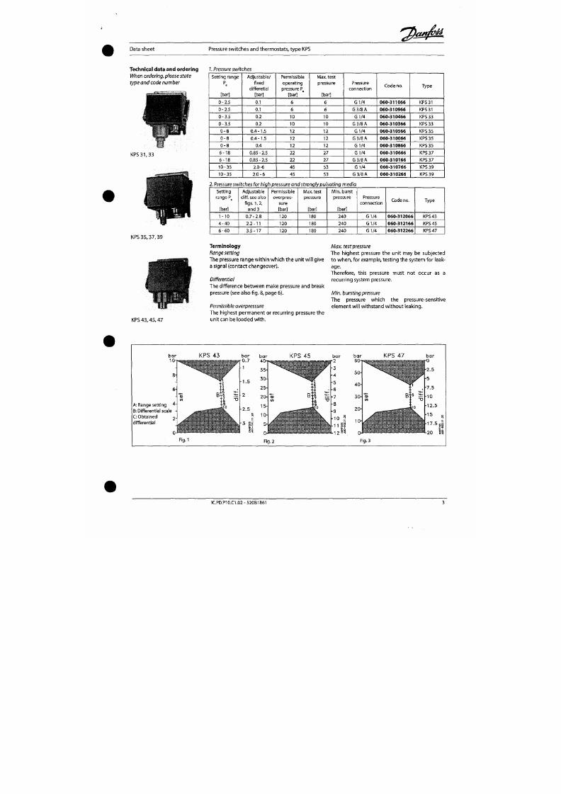
7/18/2019 M14 Thermal Fluid
http://slidepdf.com/reader/full/m14-thermal-fluid 244/486
KPS
35 , 37 , 39
10-35
10-35
2.0-6
2 . 0 -6
45
45
53
53
G l / 4
G 3/8 A
060-310766
060-310266
KPS 39
KPS 3 9
2
Pressure switches for high pressure and strongly pulsating media
Setting
range P
[bar]
1-10
4 - 4 0
6 - 6 0
Adjustable
diff. see aiso
f igs.
1,2,
and 3
0.7-2.8
2.2 -11
3.5 -17
Permissible
overpres
sure
[bar]
120
120
120
Max. test
pressure
[bar]
180
180
180
M i n . burst
pressure
[bar]
240
240
240
Pressure
connect ion
G 1/4
G 1/4
G l / 4
Code no.
060-312066
060-312166
060-312266
Type
KPS 43
KPS 45
KPS 47
Terminology
Range setting
The pressure range within w hich the unit wi l l give
a signal (contact changeover).
Max. test pressure
The highest pressure the unit may be subjected
to w he n, for example, test ing the system for leak
age.
Data sheet Pressure switches and therm ostats, type KPS
Switch
Single pole changeover (SPOT)
Contact material: Gold-plated silver contact
Contact load
(whe n Au surface is burnt away)
1.
Alternating current:
Ohm ic: 10 A,440V,AC-1
Induct ive : 6A,440V,AC-3
4A,440V,AC-15
Startin g curre nt max. 50 A (locked rotor)
2. Direct current: 12
W,
22 0 V, DC-13
Ambient temperature
KPS 31 -39 : -40 to+ 70 "C
KPS 43 -47 : -25 to+ 70 °C
Temperature of m edium
K P S 31-39 : -40 to+100°C
KPS
43-4 7:- 25 to+ 100 °C
For wate r an d seawa ter, max. 80°C.
Vibration resistance
Vibration-stable in the range 2-30 Hz,
am plitud e 1.1 m m og 30-300 Hz, 4 G.
Enclosure
IP 67 t o IEC 529 a n DIN 40050.
The pressure switch housing is enam elled
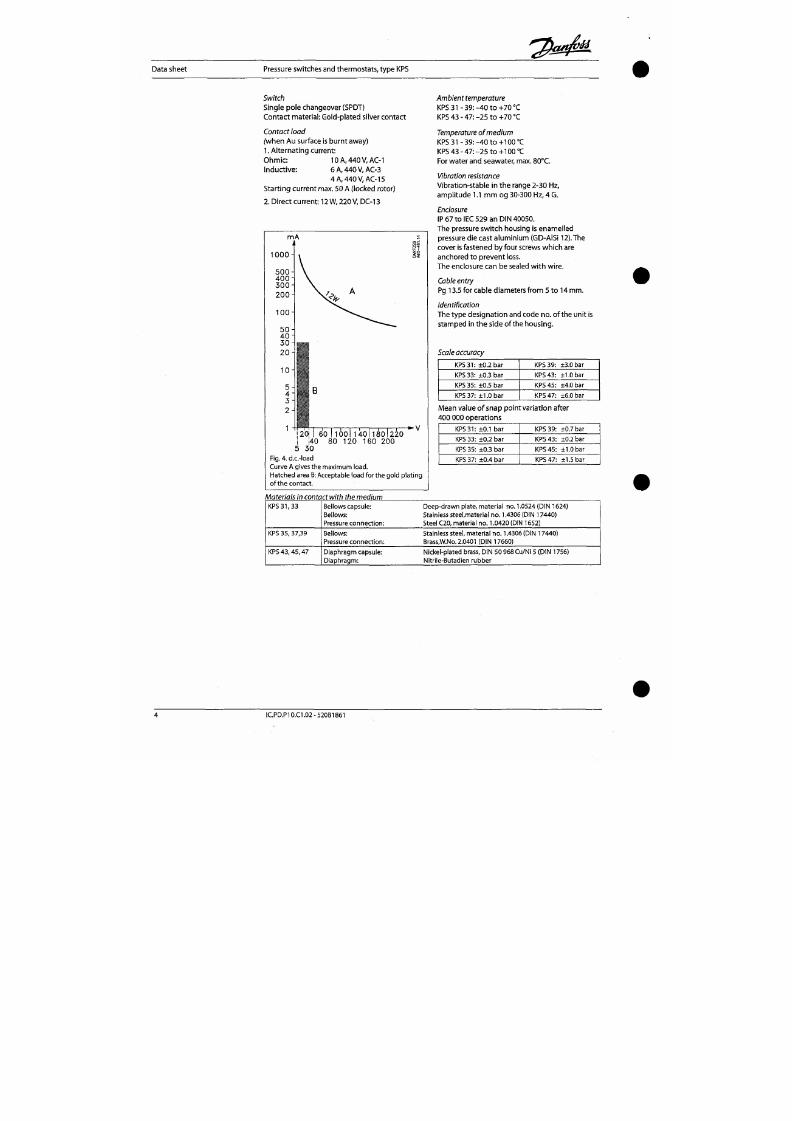
7/18/2019 M14 Thermal Fluid
http://slidepdf.com/reader/full/m14-thermal-fluid 245/486
1 0 0 0 -
pressure die cast alum inium (GD-AISi 12). The
cover is fastened by four screws whi ch are
anchored to p reven t loss.
The enclosure can be sealed wit h wi re.
Cable entry
Pg 13.5 for cable diameters from 5 to 14 mm .
Identification
The type des ignat ion and code no . of the unit is
stamped in the side of the housing.
Scale accuracy
KPS 3 1: ±0.2 bar
KPS 3 3: ±0.3 bar
KPS
3 9:
±3.0 bar
KPS 43 : ±1.0 bar
Data sheet
Pressure sw itches and th erm ostats, type KPS
Installation Installation
KPS pressure switches are fitte d wi th a 3 mm steel
mou nting plate. The units should n ot be al lowed
to hang from the pressure connect ion.
Pressure connection
When f i t t in g or removing pressure l ines, the
spanner f lats on the pressure conn ect ion should
be used to ap ply cou nter- torque.
Steam plant
To prote ct the pressure eleme nt from excessive
heat, the insert ion of a water- f i l led loop is
recommended. The loop can, for example , be
made of 10 mm copper tub e as shown in
f ig .
5.
Setting
When the pressure switch cover is removed, and
th e lockin g screw (5) is loosened, the range can
be set with the sp indle (1) whi le at the same t ime
th e scale (2) is bein g
read.
In units having an ad
justable differential, the spindle (3) must be used
to make the adjustment.
The
di f ferent ial ob tained
can be read dire ct on th e scale (4) or, w ith types
KPS 43,45 ,47, can be determined by reading the
scale value and using the nomo grams In figs. 1,2,
3 (page 3).The wo rk ing l ine for determin ing t he
differen tial mu st not intersect the shaded areas in
the nomograms.
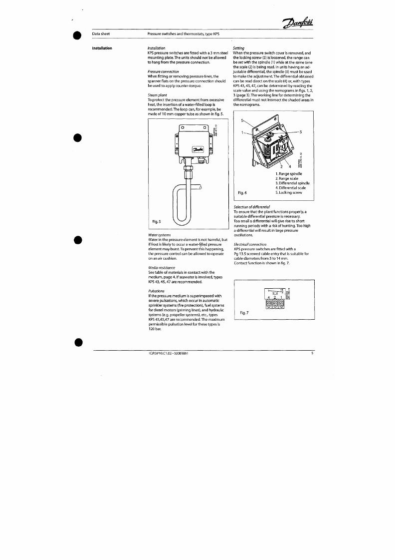
7/18/2019 M14 Thermal Fluid
http://slidepdf.com/reader/full/m14-thermal-fluid 246/486
1.
Range spind le
2. Range scale
3. Differential spindle
4. Differential scale
Data sheet
Pressure switches and therm ostats, ty pe KPS
Function 1.KPS 31
Contacts 1-2 m ake and contacts 1-4 break wh en
the pressure falls under th e set range
value.
The
contacts changeover to their initial position when
the pressure again rises to the set range value
plus the differential (see fig. 8).
I. Alarm for fallin g pressure given at the set
range value.
II. Alarm for rising pressure given at the set
range value plus the differential.
Scale setting
o 4
2
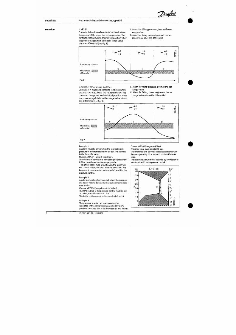
7/18/2019 M14 Thermal Fluid
http://slidepdf.com/reader/full/m14-thermal-fluid 247/486
Mechanical \^^^^^
differential
Fig.
8
2.
Al l other KPS pressure switches
Contacts 1-4 make and contacts 1-2 break w hen
the pressure rises above the set range value. The
contacts changeover to their initial position when
the pressure again fails to th e range value minus
the differe ntial (see f ig. 9).
I. Alarm for rising pressure given at the set
rangevalue.
II. Alarm for falling pressure given at th e set
range value minu s the differential.
Data sheet Pressure switches and therm ostats , type KPS
Dimensions a nd weigFit
@
- 1 1 6 -
- 9 0 -
- 6 8 -
-^ ^
y
KPS 31,33
0
= » — \— ^
1
KPS
43 ,45 ,47
1
1
1
1
S
o
1
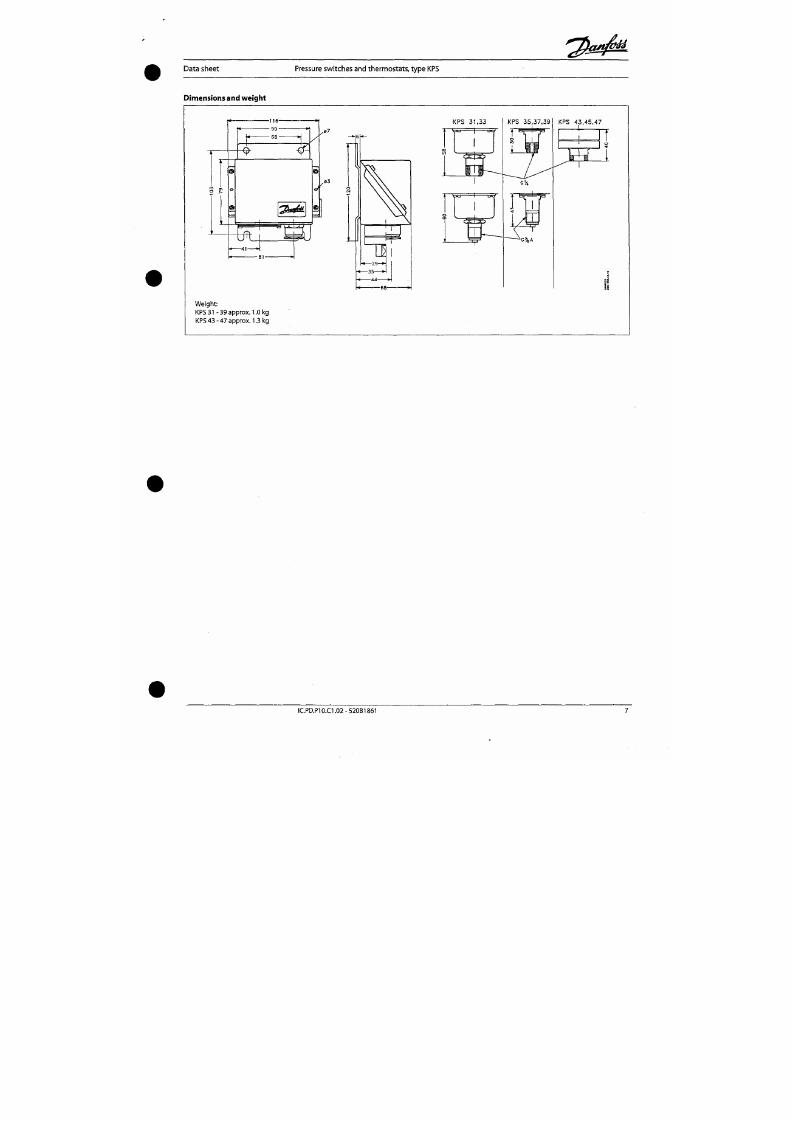
7/18/2019 M14 Thermal Fluid
http://slidepdf.com/reader/full/m14-thermal-fluid 248/486
BJ
Weight :
KPS
31
- 39 approx. 1.0 kg
KPS 43-47 appro x . 1.3 kg
Data sheet
Pressure sw itches and therm ostats, typ e KPS
Accessories
Part
Connector wi th
nipple
Connector wi th
nipple
Reducer
Adapter
Nipple
Nipple
@
© L D ©
@
@ n ) ^
@ © >
e #
^ 0
« ^
Descr ipt ion
G 3/8 connector, nipp le and washer
(10 mm)
o.d.
x 6.5 m m i.d.), for braz
ing
G 3/8 connector, nipple and washer
(10 mm
o.d.
X 6.5 mm i.d.) for welding
G3/8 X 7/16-20UNF (1 /4 f l a re )
reduct ion wi th washer
G 3/8 X1/8 - 27 MPT with washer
G 3/8 o.d X 7/16 - 20 UNF (1/4 flare)
G 3/8 A -1 /4 NPT wit h washer
Code no.
017-436866
017-422966
017-420566
060-333466
060-324066
060-333566
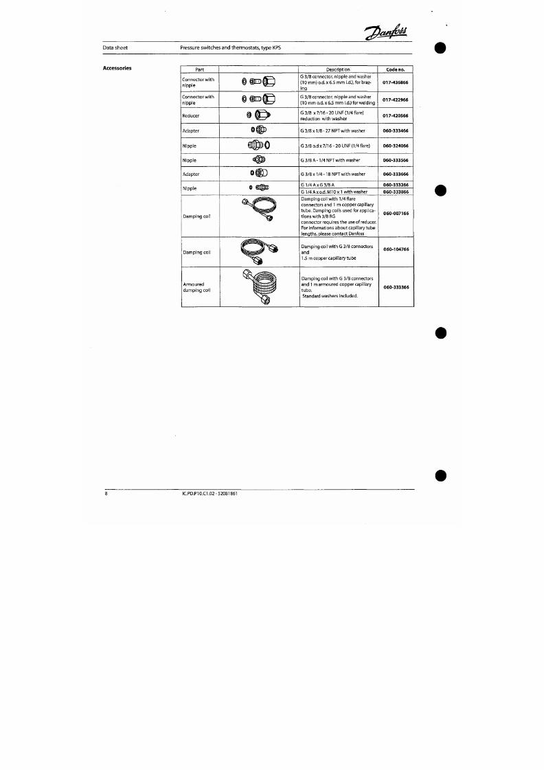
7/18/2019 M14 Thermal Fluid
http://slidepdf.com/reader/full/m14-thermal-fluid 249/486
Adapter
Nipple
Damping coi l
Damping coi l
o®D
0 @ @1
^
^
G 3/8 X1/4 -18 NPT wi th washer
G 1 / 4 A x G 3 / 8 A
G 1 /4 A X
o.d.
M l 0 X1 wit h washer
Damp ing coil wi th 1/4 f lare
connectors and 1 m copp er capil lary
t ube . Damping coils used for applica
t ions w ith 3/8 RG
connector requires the use of reducer.
For informations ab ou t capillary tube
lengths, please co ntact Danfoss
Dam ping coil wi th G 3/8 connectors
and
1.5 m copper cap il lary tub e
060-333666
060-333266
060-333866
060-007166
060-104766
Data sheet
Pressure switches and thermostats, type KPS
Tliermostats
Description
KPS thermostats are temp erature-control led
switches. The position o f the contacts depends
on the tempe rature o f the sensor and the set
scale value. In this series, special attention has
been given to m eeting demand s fo r:
• a high level of enclosure,
• robust and compact construction ,
• resistance to shock and vibr atio n.
Th e KPS series covers most ou tdo or as well as
indoor application requirements.
KPS thermostats are suitable for use in mo nitoring ,
alarm and re gulatio n systems in factories, diesel
plant, compressors, power stations and o n board
ship.
Approvals
Ship approvals
EN 60 947-4-1
EN 60 947-5-1
Det norske Veritas, Norway
American Bureau of Shipping
Lloyds Register of
Shipping,
UK
CCC,
China Compulsory Certificate
Underwriters Laboratories Inc., USA
Registro Italiano Navale, Italy
RMRS, Ma ritime Register of Shipping, Russia
Nippon Kaiji
Kyokai,
Japan
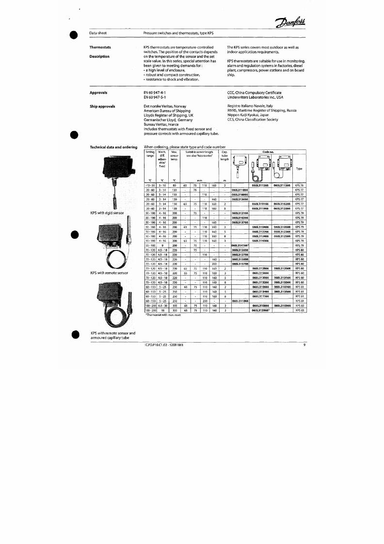
7/18/2019 M14 Thermal Fluid
http://slidepdf.com/reader/full/m14-thermal-fluid 250/486
Germanischer Lloyd, Germany
Bureau Veritas , France
Includes thermostats w ith fixe d sensor and
pressure controls with armoured capillary tube.
CCS,
China Classification Society
Technical data and orde ring
Wheno
Setting
range
"C
- 1 0 - 3 0
rdering
Mech.
diff.
adjust
able/
f ixed
°C
3 - 1 0
please state type and code number
Max.
sensor
temp.
'C
80
Suitable sensor length
see also'Accessories"
m m
65
75 110
160
Cap.
tube
length
m
2
\ C D i
" f e r
1
Code no.
1« 0
n l
o l
iKrsi
060L311266
[
JO OT
o
IÄ5
oJ
060L311366
Type
KPS 76
Data sheet Pressure switches and therm ostats, typ e KPS
nnA
i
1000-
500
400
300
200
100
Contact load (Alternating
current):
(whe n Au surface Is burned away)
Ohm ic: 10 A,440V,AC-1
Induc tive: 6 A, 440 V, AC-3
4 A, 440
V,
AC-15
Starting c urrent m ax. 50 A (locked rotor)
Am bient temperature -40 to +70 °C
Vibration
resistance
Vibration-stable in the range 2-30 Hz, amplitude
1.1 mm og 30-300 Hz, 4 G.
Enclosure
IP 67 to IEC 529 an d DIN 40050.
The thermostat housing is enamelled pressure
die cast alu min ium (GlD-AISi 12).The cover is
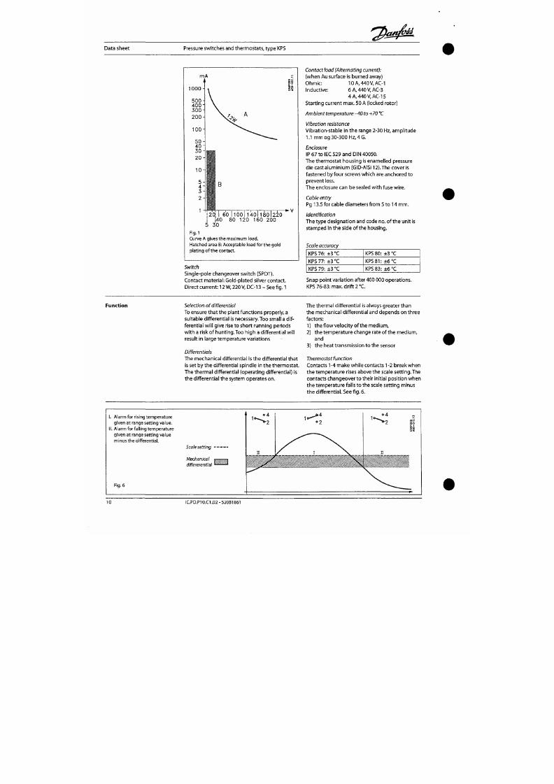
7/18/2019 M14 Thermal Fluid
http://slidepdf.com/reader/full/m14-thermal-fluid 251/486
60 I 1001 1401180 1220
80 120 160 200
Fig.l
Curve A gives the maximum load.
Hatched area
B:
Acceptable load for
the
gold
plating of the contact.
fastened by four screws which are anchore d to
preven t loss.
The enclosure can be sealed wi th fuse wire .
Cable
entry
Pg 13.5 for cable diameters from 5 to 14 m m .
identification
The type des ignatio n and code no. of the u nit is
stamped in the side of the housing.
Scale accuracy
KPS 76: ± 3 "C
KPS
77:
± 3 °C
KPS
80:
+3 °C
KPS
81:
±6°C
Data sheet
Pressure switches and the rmosta ts, type KPS
Installation
Installation
Location of u nit :
KPS
thermostats are designed t o
withstand the shocks that
occur,
e.g. in ships, on
compressors and in large machine installations.
KPS
thermostats w ith remote sensor are f i t ted
wi th a base of
3
m m steel plate for f ix ing to
bulkheads, etc. KPS thermostats with bulb sensor
are self-support ing from th e sensor pocket.
Resistance to media
Ma terial specifications for sensor pockets:
Sensor
pocket,
brass
The tub e is made of
M s
72 to DIN 17660, the
threaded por t ion of So Ms 58Pb to DIN 17661.
Flow velocity o f the med ium is also of s ignif i
cance. (The optimum flow velocity for liquids is
about 0.3 m/s).
For permissible media pressure see fig. 2.
ba r
2 0 0 -
150 -
100 -
80 -
6 0 -
4 0 -
3 0 -
2 0 -
y—Brass j — S t a i n l e s s s t e e
1
-i
/
.S
ii
- 4 0 ' 6 2 0 ' 6 0 ' l b o ' l 4 o ' l 8 o ' 2 2 o ' 2 4 o ' 2 8 o ' °C
Fig. 2 . P e r m i s s i b l e m e d i a p r e s s u r e o n t h e
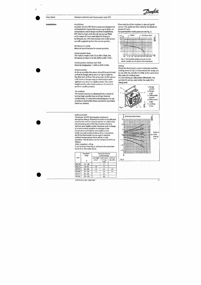
7/18/2019 M14 Thermal Fluid
http://slidepdf.com/reader/full/m14-thermal-fluid 252/486
Sensorpod<et, stainless steel 18/8
Mater ial designation
1.4305
to DIN 17440.
Sensor position
As far as possible the sensor should be pos itione d
so tha t its long itud ina l axis is at righ t angles to
the dire ct ion of f low. The act ive part of the sensor
is 013 mm x 50 mm long on thermostats wit h
rigid sensors and 2 m cap illary tu be. The active
length o n the other thermostats is 70 mm (5 m
and 8 m capillary tubes).
The
medium
The fastest react ion is obtained from a me dium
having high specif ic heat and h igh therm al
Setting
Whe n the thermosta t cover is removed, and the
locking screw (5, fig. 3) is loosened, th e range can
be set with the spindle (1) whi le at the same t ime
the scale (2) is being
read.
In units having an adjustable differential, the
spind le (3) can be used w hile the scale (4) is
being
read.
5 \ ^
- — 3
1.Range
s p i n d l e
2 . R a n g e
sca le
3 . D i f f e ren t i a l
Data sheet
Pressure sw itches and therm ostats, ty pe KPS
Electrical connection
KPS thermostats are fitted with a Pg 13.5 screwed
cable entry suitable for cables from 5 to 14 mm .
Contact functio n is shown in Fig. 5
Fig.
5
4 2 1
M
i
Examples Example 1
A diesel engine w ith cooling water tem perature
of 85 °C (normal). An alarm must be tr iggered if
the c ooling water tempe rature exceeds 95 "C.
Choose a KPS 80 therm osta t (ra nge 70 to 120 °C).
Main s pind le setting: 95 °C.
Example 2
Find the necessary scale correction for a KPS 80
set at 95 °C in 50 °C am bient tem pera ture .
The relative scale setting Z can be calculated
from the fol lowing formula:
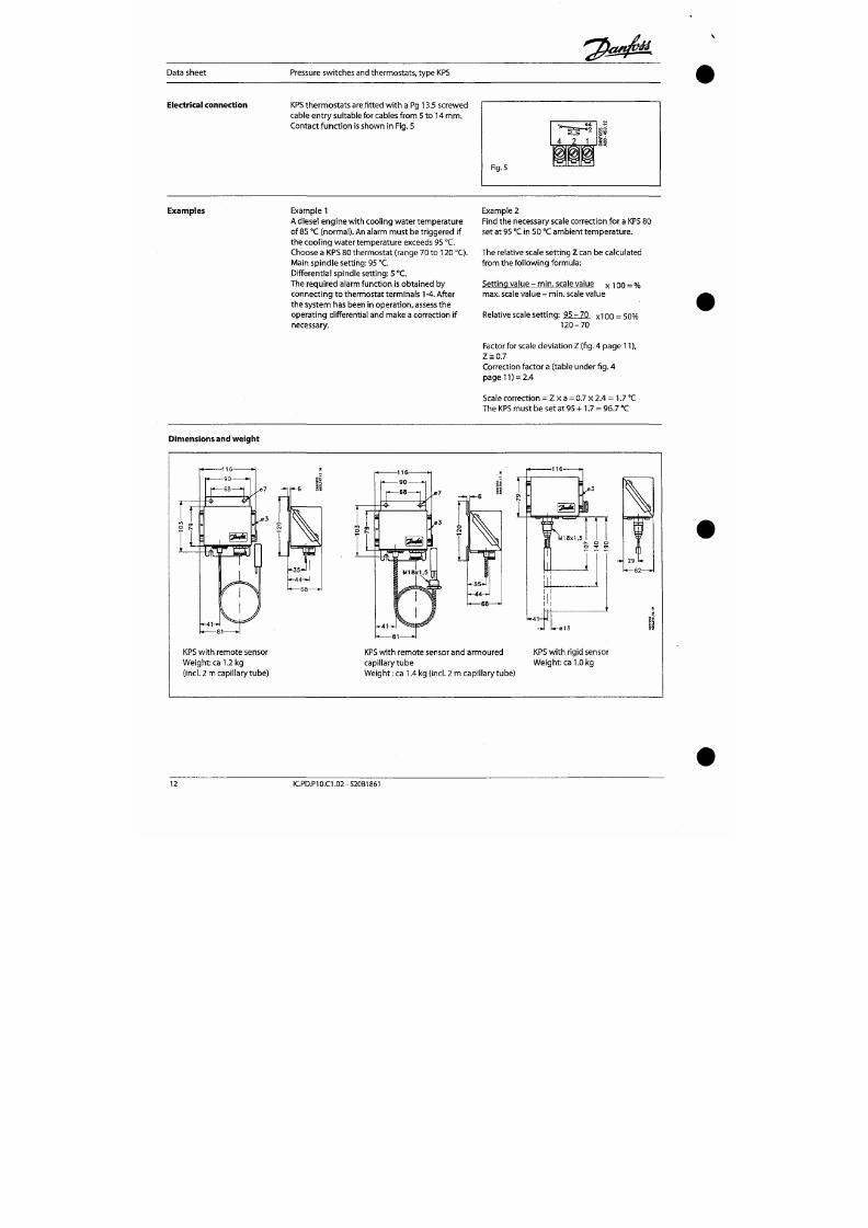
7/18/2019 M14 Thermal Fluid
http://slidepdf.com/reader/full/m14-thermal-fluid 253/486
Differentia l spind le settin g: 5 °C.
The required alarm function is obtained by
connecting to thermostat terminals 1 -4. After
the sys tem has been in operati on, assess the
operating differential and make a correction if
necessary.
Setting value - m in , scale value x 100 = %
max. scale value - mi n. scale value
Relative scale set ting : 95 - 70 x100 = 50%
1 2 0 - 7 0
Factor for scale dev iation Z (fig. 4 page 11),
Z sO.7
Correction factor a (table under
f ig.
4
page 11) = 2.4
Scale corre ctio n = Z x a = 0.7 x 2.4 = 1.7 °C
Th e KPS m ust be se t at 95 + 1.7 = 96.7 °C
Data sheet
Pressure switches and therm ostats, type KPS
Accessories:
Sensor pockets
fo r KPS thermo stats
O
M g
V~
m A » 1 /
M 1 Ö X 1 . 3
Sensor
Brass
Brass
Brass
Brass
Brass
A
m m
65
75
75
75
75
no
110
110
110
160
160
200
200
200
Thread
B
1/2 NPT
1/2
NPT
G 1/2 A
G
3/8 A
G 1/2 A
(ISO
228/1)
1/2 NPT
G 1/2 A
G 1/2 A (ISO 228/1)
G 3/4 A (ISO 228/1)
G 1/2
A
G 3 /4 A (ISO 228/1)
G 1/2 A
G 1/2 A (ISO 228/1)
G 3/4 A (ISO 228/1)
Code no.
0 6 0 1 3 2 6 5 6 6
060L326466
060L326266
060L326666
0 6 0 1 3 2 8 1 6 6
060L328066
060L327166
060L340666
060L340366
060L326366
0 6 0 L 3 4 0 5 6 6
060L320666
060L340866
060L340266
Sensor
S t e e l
8/8
Steel 18/8
Steel 18/8
Steel 18(8
A
m
75
110
110
160
200
200
I
Thread
B
G1/ 2A
G 1/2 A
1/2 NPT
G 1/2 A
G 1/2 A
G 3/4 A
Code no.
060L326766
0601326866
060L327066
060L326966
060L323766
060L323866
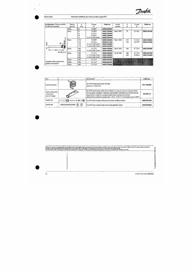
7/18/2019 M14 Thermal Fluid
http://slidepdf.com/reader/full/m14-thermal-fluid 254/486
Supplied without gland nut,
gask
sts
ana wasner
Brass
Brass
Brass
250
330
400
G 1/2
A
G 1/2
A
G 1/2 A
0 6 0 L 3 2 5 4 6 6
0 6 0 L 3 2 5 5 6 6
0 6 0 L 3 2 5 6 6 6
>
I - ' - lA
V
*'
• • ^ ^
- •
Part
Clamping band
Heat-conduct ive
Descript ion
For KPS thermostats w i th remote
sensor (L = 392 mm)
For KPS thermostats with sensor fitted in a sensor pocket. Compound for
f i l l ing sensor pocket to imp rove heat t ransfer betwe en pocket and sensor.
Code no.
017 -420466
Instructions
Pressure
Transm itters
Types MBS 32, MBS 33, MBS 33M,MBS 2050, MBS 2100, MBS 2150, MBS 2200, MBS 2250
MBS 3000, MBS
3050, MBS 3100,
MBS
3150,
MBS 3200, MBS 3250,
MBS 4010, MBS 4050, MBS 4500, MBS 4510
A
Elektrisk tilslutning :
Electrical conne ction:
Elektrischer Anschluss:
Raccordement électrique:
Conexiön electrica:
Connessione elettrica:
Se produktskilt
See
product label
Siehe Produktschild
Voir etiquette du p roduit
Ver la pecatina en el produao
Vedi etichetta sulla confezione
lEC 947-5-2, M 12 x1
ISO15170A1-3.2-Sn/Au
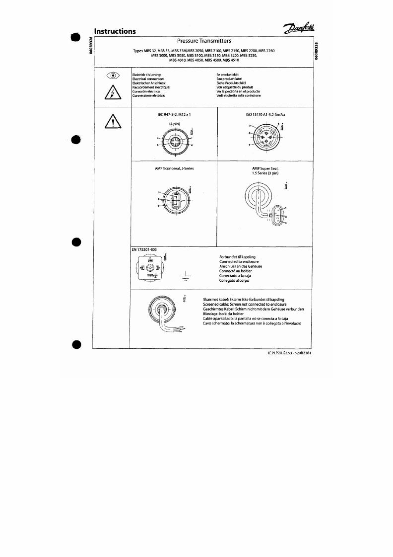
7/18/2019 M14 Thermal Fluid
http://slidepdf.com/reader/full/m14-thermal-fluid 255/486
A
(4 pin)
AMP Econoseal, J-Series
AMP Super Seal,
1.5 Series (3 pin)
Instructions
A
^^
MBS 32, MBS 33
MBS33M
MBS
2100,
MBS
2200,
MBS
3000,
MBS 3100,
MBS
3200, MBS
4500
MBS
2050,
MBS 2150,
MBS 2250, MBS 3050,
MBS
3150,
MB S
3250,
MBS 4050
MBS 4010
MBS 4510
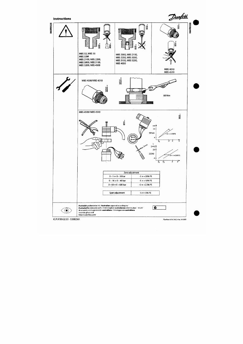
7/18/2019 M14 Thermal Fluid
http://slidepdf.com/reader/full/m14-thermal-fluid 256/486
^
MBS4500/MBS4510
60 Nm
MBS 4500/MBS 4510
AALBORG
I N D U S T R I E S
Aalborg Industr ies BV
P.O. Box 145
3200 AC Spijkenisse
Ohm w eg 8
3208 KE Spijkenisse
The Netherlands
Tel. +31 (0)181 650 500
Fax +31 (0)181 650 501
Traderegister Rotterdam
No .
24234179
VAT No. NL0081.91.694.B.01
E-mail : r tmw®aalborg-industr ies.nl
h t tp : / /www.aalborg- indus t r ies .n l
Bankers: Fort is Bank, Rotterda m
Accoun t No. 25.75.69.618
IBAN No . NL85FTSB0257569618
BIC Code FTSBNL2R
Cer t i f ied
Company
WORKING PRINCIPLE OF Q UICK OPENING V ALV E
The Econ quick opening valve Fig. 100/432 SO, 100/433 SO, 100/436SO and 100/43 7SO
has been designed to open a thermic oil (fuel) line rapidly in case of em ergency.
Operating can be manual, pneumatic or hydraulic. The last two options make it possible
to open the valve by rem ote controle. Hydraulic operation can be effected by means of
an impulse unit Fig.107 and Fig. 108.
Fluid flow is with the pressure above the disc. The reason for this is that the line
pressure helps closing the disc when the valve is closed.
Let's assume that the valve is open. To get the valve in operational position, start by
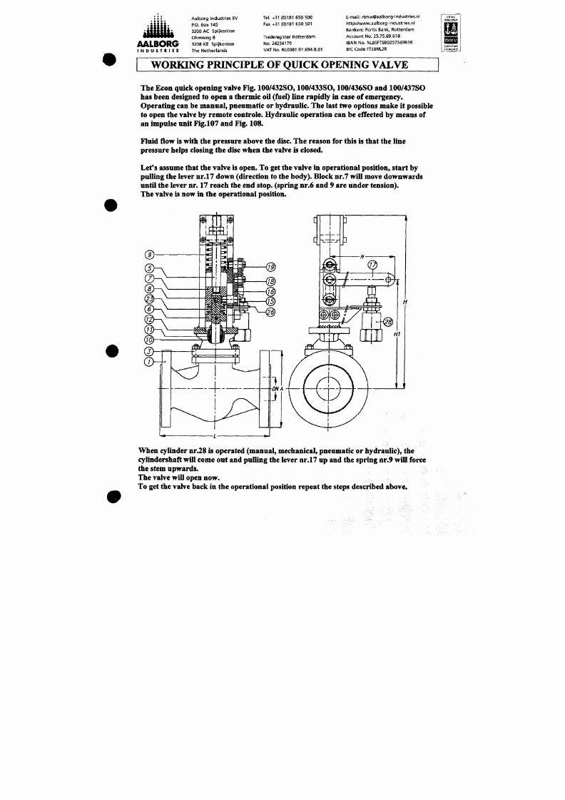
7/18/2019 M14 Thermal Fluid
http://slidepdf.com/reader/full/m14-thermal-fluid 257/486
pulling the lever nr.17 down (direction to the body). Block nr.7 will move downw ards
untU the lever nr. 17 reach the end stop, (spring nr.6 and 9 are under tension).
The va lve is now in the operational position.
: : : :
A A L B O R G
I N D U S T R I E S
Differential Pressure Switch
With integral Working Pressure Gauge and Micro Switch
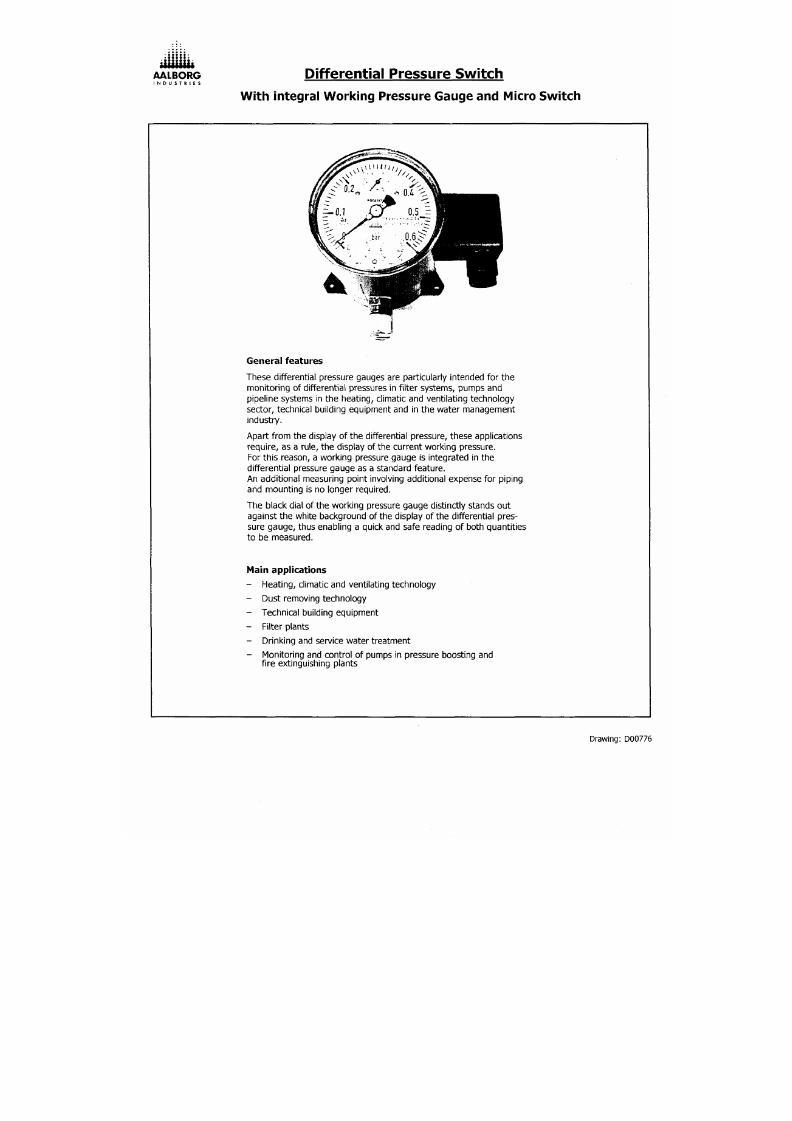
7/18/2019 M14 Thermal Fluid
http://slidepdf.com/reader/full/m14-thermal-fluid 258/486
General features
These differential pressure gauges are particularly intended for the
Scale ranges
per EN 837
Differential pressure gauge: 0 - 0.6 bar
Working pressure gauge:
0 - 0,6 bar
146
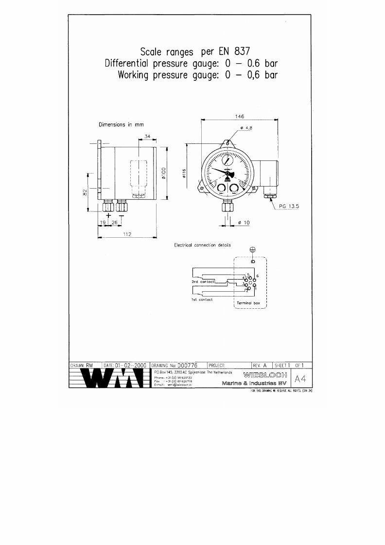
7/18/2019 M14 Thermal Fluid
http://slidepdf.com/reader/full/m14-thermal-fluid 259/486
Dimensions
in mm
oo
« I
measuring medium chambers
A A L B O R G
I N D U S T R I E S
Design and operating principle.
Pressure p' and p^ are given in + and
separated by an elastic d iaph rag m( l).
The differential pressure (Ap=pi - p^) causes axial movement (measuring
travel) of the diaphragm against the measuring range spring (2).
The transmission of the differential pressure proportional to the th e
measuring travel to the movement (4) within the indicating case and to the
plungers of the microswitches (5) and is carried out pressure sealed and
with little friction by means of connection rod (3).
The overpressure protection is provided by contoured metal bolsters for the
elastic diaphragm (6).
The adju stme nt of the switchpoint is made by setpoint screws accessible
from the fro nt (7). The assistant scales (8) enable a relatively accurate
adjustment of the sw itchpoints over 270< ° and indicate the setpoint tha t is
I l lustrat ion of operating principle
3
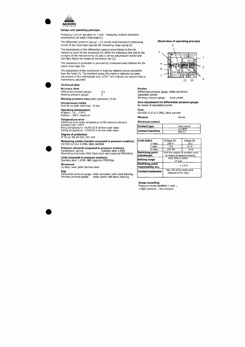
7/18/2019 M14 Thermal Fluid
http://slidepdf.com/reader/full/m14-thermal-fluid 260/486
momentarily adjusted.
Technical data
Accuracy class
Differential pressure gaug e: 2,5
Working pressure gauge: 4
Working pressure max.(static pressure) 25 bar
Overpressure safety
Must be on both sides max. 25 bar
Operat ing temperature
Ambient: -10....+70°C
Medium: +90°C maximum
Pointer
Differential pressure gauge: white aluminium
adjustable pointer
Working pressure gauge: black plastic
Zero adjustment for differential pressure gauge
By means of adjustable pointer
Case
GD-AISi 12 (Cu) 3.2982, black painted
Window Acrylic
AALBORG
I N D U S T R I E S
Aalborg Industr ies NL BV
P o Box 145
3200 AC Spljkenisse
Ohmweg 8
3208 KE Spljkenisse
The Netherlands
Tel. +31 181 650 500
Fax +31 181 650 501
Traderegister Rotterdam
No. 24234179
VAT No. NL0081.91.694.B.01
E-mail: r tmw@aalborg- indus tnes .n l
h t tp : / /www.aalborg- indus t r ies .com
Bankers: Rabobank, Hoogvl iet
Accou nt No. 32.95.68.094
Swif t -address: RAB0NL2U
Magnetically controlled level Indicator, type ITA
Indicates the fluid level of irritant, toxid or inflammable media with a se
paration of the measurement and indication area
The magnetic transfer of the fluid level from the tank to the indicator is
continuous and vibration-resistant
May be used for level measurements in non-pressurised and presssuri-
sed vessels
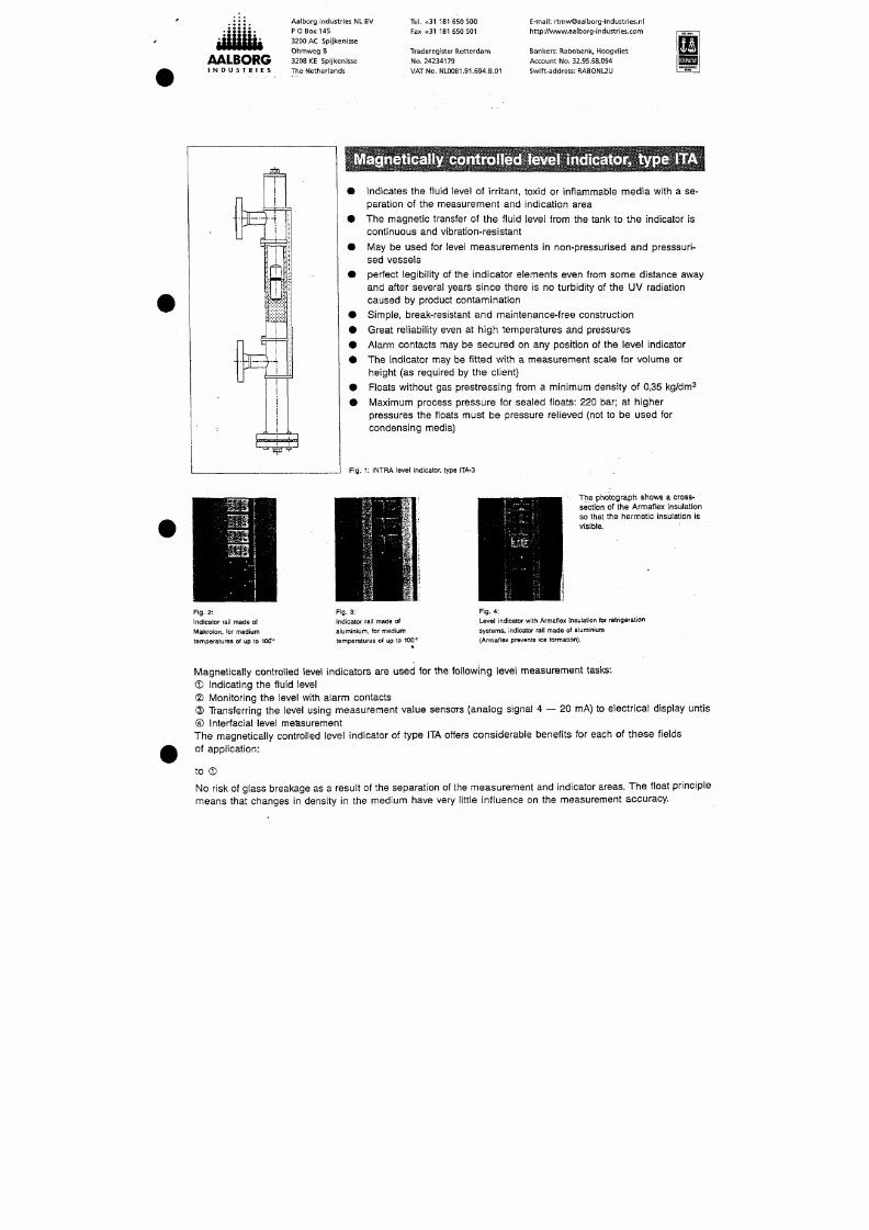
7/18/2019 M14 Thermal Fluid
http://slidepdf.com/reader/full/m14-thermal-fluid 261/486
perfect legibility of the indicator elements even from some distance away
and after several years since there is no turbidity of the UV radiation
caused by product contamination
Simple, break-resistant and maintenance-free construction
Great reliability even at high temperatures and pressures
Alarm contacts may be secured on any position of the level indicator
The indicator may be fitted with a measurement scale for volume or
height (as required by the client)
Floats without gas prestressing from a minimum density of 0,35 kg/dm^
Maximum process pressure for sealed floats: 220 bar; at higher
pressures the floats must be pressure relieved (not to be used for
f
to®
Magnetic level indicators
can be
equipped with
an
arbitrary num ber
of
switch contacts.
In
contrast
to
electric
float switches, switch contacts
may be
installed
at any
position
of the
stand pipe. Wherever additional float
chambers are used for f loat switches, magnetically controlled level indicators offer a considerable price
advantage.
to
®
Electrical level measurement transducers which use the displacem ent principle must be recalibrated each time
the fluid density
is
changed.
The pr ice
of a
magnetically controlled level indicator with integral electrical measurement transducer
is
considerably lower than level measurement transducers.
The reed chain with
an R/l
measurement transducer
can be
changed without interuppting operation.
The measurement chamber
is
hermetically sealed
—
there
is no
contact between
the
f luid chamber and
the
reed chain.
Anz e ige r
T y p : 420
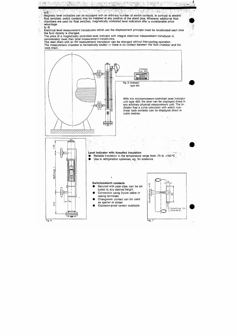
7/18/2019 M14 Thermal Fluid
http://slidepdf.com/reader/full/m14-thermal-fluid 262/486
Fig. 5: Indicator
type 420
1250ir.v^i
With
the
microprocessor-controlled level indicator
unit type 420,
the
level
can be
displayed direct
in
any arbitrary physical measurement unit.
The in
dicator
has a
curve calculator with which
non
linear tank contents
can be
displayed direct
in
cubic metres.
l i
INTRA level indicators — overview of standard deslg
Level indicators for low and medium pressures,
series ITA-3/6/7
• Parts in contact with tine me dium made as
standard of stainless steel (316Ti)
• Pressure ranges PN16 to PN 64
• DIN or AN SI connection flange s
• precise float desig n for the opera ting cond itions
• Versions up to 12 m length (in two sections )
• Special ma terials for special opera ting
conditions:
— titanium, Hastelloy C4, Inconel 625, 1.4539
— PTFE lining . (PN16 only)
• Acces sories: vent and drain flanges, valves,
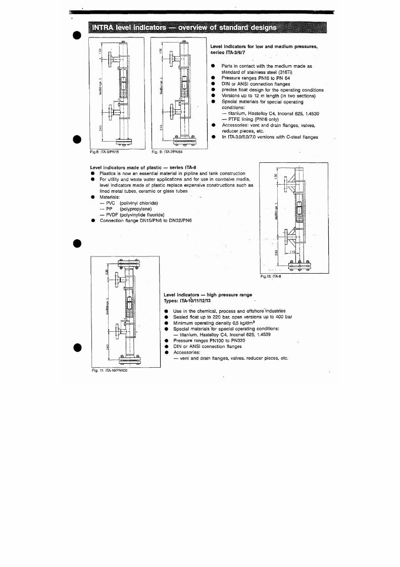
7/18/2019 M14 Thermal Fluid
http://slidepdf.com/reader/full/m14-thermal-fluid 263/486
reducer pieces, etc.
• In ITA-3.0/6.0/7.0 version s w ith C-stee l flan ge s
Fig.8:
ITA-3/PN16
Fig.
9: ITA-7/PN64
Level indicators made of plastic — series ITA-8
• Plastics is now an essential material in pipline and tank construction
• For util ity and waste water applications and for use in corrosive me dia,
level indicators made of plastic replace expensive constructions such as
lined metal tubes, ceramic or glass tubes
O
1
— 1 —
1
i
1
i—
U v e l indicators - - special versions and additionat equipment
Special versions:
a) Two-piece versions
to order or for measurement lengths of over 6 m
b)
Steam jacket
with thread or flange connection; for heating the indicator with steam or hot water,
eg . for viscous media
c) Level indicator with
PTFE lining,
for use in corrosive media
d) Level indicator in
GL design
(Germanischer Lloyd)
e) To act as an
overfilling guard
for tanks for storing inflammable and non-flammable fluids which pose a
threat to water
f) ITA cryogenic version for refrigerants
g) Special versions to meet the client's requirements for specific operating conditions
Additional equipment:
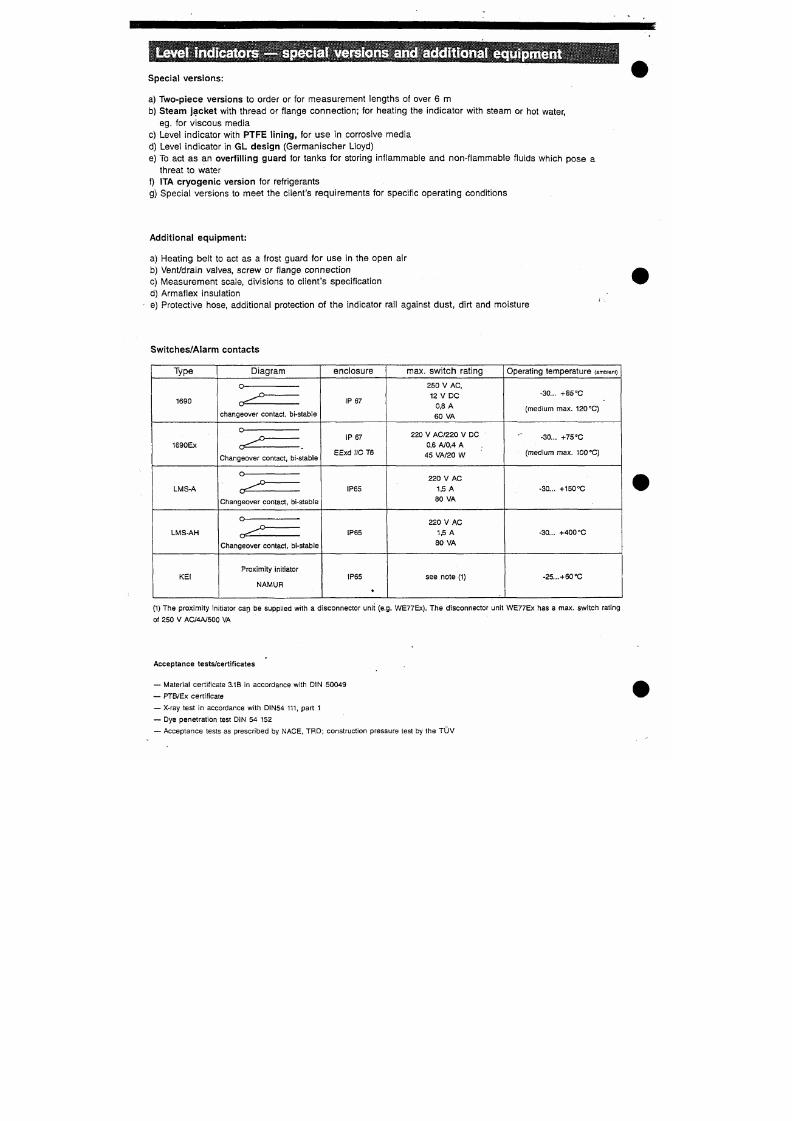
7/18/2019 M14 Thermal Fluid
http://slidepdf.com/reader/full/m14-thermal-fluid 264/486
a) Heating belt to act as a frost guard for use in the open air
b) Vent/drain valves, screw or flange connection
c) Measurement scale, divisions to client's specification
d) Armaflex insulation
e) Protective hose, additional protection of the indicator rail against dust, dirt and moisture
Switches/Alarm contacts
Type Diagram
enclosure
max. switch rating
Operating temperature (ambient)
Magnetically Operated Levelgauges Type ITA-3 ... ITA-13
Instal lat ion and operat ion manual
I . I n s t a l l a t i o n
As soon as instrument is received it should be carefully inspected to determine
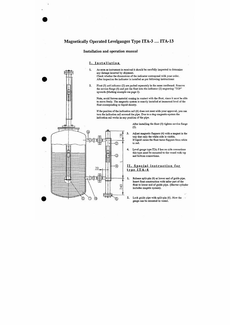
7/18/2019 M14 Thermal Fluid
http://slidepdf.com/reader/full/m14-thermal-fluid 265/486
i-x
any damage incurred by shipment.
Check whether the dimens ions of the indicator correspond with your order.
After inspection the indicator is installed as per following instructions:
Float (3) and indicator (2) are packed seperately in the sam e cardboard. Remove
the service flange (5) and put the float into the indicator (2) engraving "TOP"
upwards (Marking example see page 2).
Note, avoid ferrous material coming in contact with the float, since it must be able
to move freely. The magnetic system is exactly installed at immersed level of the
float correspondmg to liquid density.
i n . Electric alarm con tacts
Electric alarm contacts can be m ounted in
any position and direction. Th ere is a collection of alarm
contacts selected by temperature and electrical
load.
cable 3m
(standard)
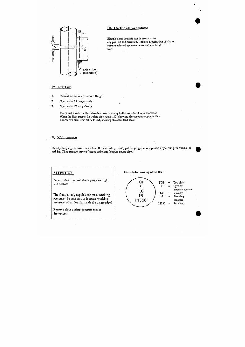
7/18/2019 M14 Thermal Fluid
http://slidepdf.com/reader/full/m14-thermal-fluid 266/486
I V . S t a r t u p
1. Close drain valve and service flange
2 . Open valve lA very slowly
3 . Open valve IB very slowly
The liquid inside the float chamber now moves up to the same level as in the vessel.
When the float passes the wafers they rotate 180° showing the observer opposite face.
AALBORG
N o U s T « i t s
Surface-mounting Thermostat
Series A TH
^
^ ^ i
^ ^ ^ ^ ^ -
7/18/2019 M14 Thermal Fluid
http://slidepdf.com/reader/full/m14-thermal-fluid 267/486
"
( *
Description
All necessary settings and possible adjustments are described in these Operating Instructions. If, however,
any difficulties should arise during start-up you are asked not to carry out any man ipulations on the
instruments which are not permitted.- You could endanger your rights under the instrument warranty.-
Please contact Aalborg Industries NL B.V.
Phone:
The Netherlands (+31 181 650 500)
Arrangements to DIN 3440 as
Type designation
ATH.-.. /
Thermostat, surface-mounting,
AALBORG
I N D U S T R I E S
Temperature probe w i th and w i thout pocket
The temperature is sensed by means of the temperature
probe.
The prob e must be immerse d in the medium for
its entire length, otherwise there are appreciable
deviations in the switching point.
1 cap illary
2 temperature probe
3 pocket
'A/ith probe mounting ES
the probe is secured by fitting attached to the capillary at
the factory.
Securing the thermostat case
UJ
w
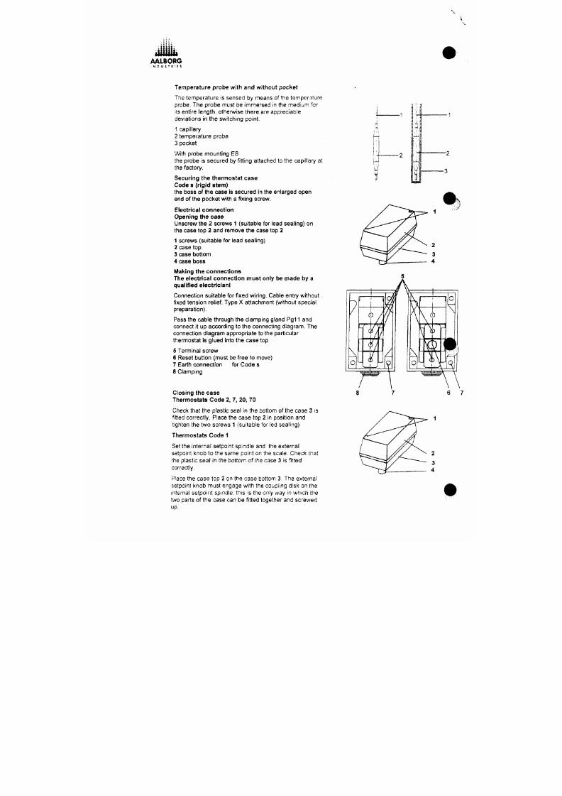
7/18/2019 M14 Thermal Fluid
http://slidepdf.com/reader/full/m14-thermal-fluid 268/486
Code s (rigid stem)
the boss of the case is secured in the enlarged open
end of the pocket w ith a f ixing screw.
Electrical connection
Opening the case
Unscrew the 2 screws 1 (suitable for lead sealing) on
the case top 2 and rem ove the case top 2
1 screws (suitable for lead sealing)
2 case top
3 case bottom
4 case boss
AALBORG
I N D U s
T
« 1
E
s
Different ia l ( l iqu id- f i l led)
monitor TW
monitor
STW(STB)
Differential
monitor TW
monitor
3+1%
6+2%
1.5±0.5%
5±1%
9+2/-1%
2±1 %
(gas-fi l led)
5+5%
9+2%
1.5±0.5%
standard
optional
extra charge
standard
optional
extra charge
standard
optional
extra charge
Permit ted ambient temperature at probe
in operation
max. end of scale +15 °C
min,
-50°C
Permit ted storage temperature
thermostat head, capillary, temperature probe
max. +50°C
min.
- 5 0 X
Operating med ium
water,
oil, air, dry steam
Time constant
in water 45 sec max. in oil
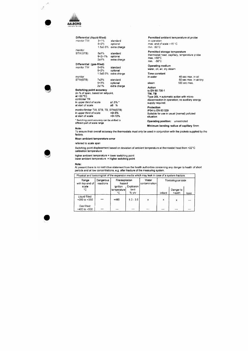
7/18/2019 M14 Thermal Fluid
http://slidepdf.com/reader/full/m14-thermal-fluid 269/486
^
STW(STB)
7±2%
9+3%
2±1%
standard
optional
extra charge
steam
60 sec max, in air/dry
120 sec max.
Action
to EN 60 730-1
TW , IB
Type 2BL = automatic action with micro-
disconnection in opera tion; no auxiliary energy
supply required.
Protection
IP54 to EN 60 529
Suitable for use in usual (normal) polluted
situation
Switching point accuracy
(in % of span, based on setpoint,
at +22 "C)
controller TR
in upper third of scale ±1.5 % *
at start of sca le ±6 %
monitor/limiter TW. STB, TB. STW(STB)
in upper third of scale +0/-5%
at start of scale +0/-10%
AALBORG
: N D ; s • « : t s
Connection diagrams
Code 2
With changeover contact
, (
1
1 1 - h
' — ' r
2 4
1 -4 -•
J
i
1
2
4
f ^ ^ ^
After the temperature has dropped by approx. 10% of
span below set limit (safe temperature limit) the
1 _
I
I
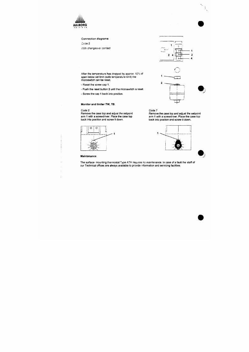
7/18/2019 M14 Thermal Fluid
http://slidepdf.com/reader/full/m14-thermal-fluid 270/486
microswitch can be reset.
- Reset the screw cap 1.
- Push the reset button 2 until the microswitch is reset.
- Screw the cap 1 back into position.
Monitor and limiter TW, TB.
Code 2
Remove the case top and adjust the setpoint
arm 1 with a screwdriver. Place the case top
bacl< into position and screw it dow n.
2
•
1
q=^
V
C ode ?
Remove the case top and adjust the setpoint
arm 1 with a screwdriver. Place the case top
back into position and screw it down.
(iE
Industry controllers K FM 93 W0.
operating instructions
B 93W 0_ E
- page
1
-
1 Digital display actual valu e
2 2nd digital display attand ant unit of
measure or name of input
3 LED-display relais func tion
4 Key for setpoint and param eter mode
5 Setpoint adjustment
6 Param eter mode lock switc h (back face)
DIN-certificate: TR (TW) 949 ..
3
:: Kg
Q QQ
3
1
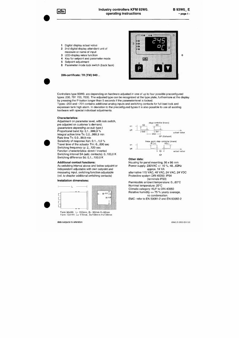
7/18/2019 M14 Thermal Fluid
http://slidepdf.com/reader/full/m14-thermal-fluid 271/486
Controllers type 93W0. are depending on hardware adjusted in one of up to four possible preconfigured
types: 200, 701 70 0, 700E. The adjusted type can be recognized at the type plate, furthermore at the display
by pressing the P-button longer than 5 seconds if the parameterlevel is locked.
Types -2 00 and -70 1 contains additional analog inputs and switching contacts for full load lock and
expansian tank high alarm. In deviation to the preconfigured types it is also possible to use all existing
hardware with special individual adjustments.
Indu stry con troller type 9... B 9... E
Installation and conn ection -
page 2 -
Installation:
Before installation inspect the controller for any visible signs of damage caused during transport
Check power supply ace. to name plate.
Push the housing from the front into the DIN- panel cut-out and secure from behind with the
fastening devices sup plied.
Electrical wiring:
Plug bar on the back face of the controller; connect up the controller at the rear following the
wiring diagram; wire cross section m ax. 1,5 mm ^
- To avoid cross interference
all low voltage measuring lines and pilot wires
must be encased
in a shielded cable (the shielding must be earthed one-sided).
- The control leads must be fused
externally lo
protect the output relays.
- Phase wire and neutral wire must not be transposed.
7/18/2019 M14 Thermal Fluid
http://slidepdf.com/reader/full/m14-thermal-fluid 272/486
P utting into operation:
Switch on power supply. Digital display and control lamps will light up according to
the setpoint after some seconds. If nothing happens check the fine-wire fuse on the back panel
of the controller and the electrical wiring. Adjust set value and check other adjustments.
IVIaintenance:
All electronic controllers In the KFM range are virtually maintenance-free.
Provided that the
controller is correctly installed and put into operation and is protected against mechanical
damage and inadmissible operating conditions, it should give years of trouble-free service.
In case of faults
repair wo rk by the customer should be restricted to the externally accessible
leads and connections and components the customer is expressly permitted to deal with himself,
Industry controller KFM 9.
Operation
B 9 ... E
- page 3
Operating status:
The upper display shows the actual value (channel / meas uring input 1),
6 3 5
the lower display shows the attendant unit of measure (°C, °F, %, bar...)
(depending on the settings)
types 93W00 200 and 701
only:
Switch over the upper display to the further actual values by pressing the O key,
the lower display shows the number of the attendant measuring input
("Ist2" = return temperature)
or an abbreviation of the input's name ("EP tH" = exp ansion tank high).
Return to operating level:
Press O - key shortly (or automatically after 30 seconds without any key-action)
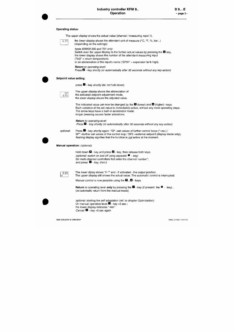
7/18/2019 M14 Thermal Fluid
http://slidepdf.com/reader/full/m14-thermal-fluid 273/486
Setpoint value setting:
5P
6 3 5
press B - key shortly (do no t hold down)
Th e upper display shows the abbreviation of
the activated setpoint adjustment mode,
the lower display shows the adjusted value.
The indicated value can now be changed by the D (lower) and O (higher) -keys.
Each variation of the set value is immediately active, without any more operating steps.
The arrow keys have a built-in accelerator mode:
Industry controller type KFM 9.
Parameter level
B 9... E
-
page 4
Access from operating level.
Unlock
the access first:
Turn the switch on the rear panel of the controller to position "U " = unlocked
(Lock acce ss after the adjustments: S witch position to "L" = locked).
After the parameter level (refer to the instructions to each level) has been invoked,
the first setting is shown and can be modified.
It is n ot possible to invoke the parameter level whe n the switch is locked.
In this case the d isplay shows the abbreviation o f
the
configured con troller type.
Confirm the entry and / or
move on
to next param eter:
press the Q -key briefly
Settings in detail:fnof ava ilable on all types)
Invoke: Hold down the B - key for more than 5 sec until the display changes
P
t y p
70 /
Level 1:
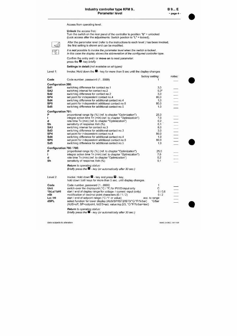
7/18/2019 M14 Thermal Fluid
http://slidepdf.com/reader/full/m14-thermal-fluid 274/486
Code
Code number, password (1...9999)
factory setting:
1
Configuration 200:
Sd 1
switching difference for contact no.1
SA2 switching interval for contact no.2
Sd2 switching difference for contact no.2
SP 4 set point for independent contact no.4
Sd4
switching difference for additional contact no.4
SP 5
set point for independent additional contact no.5
Sd5
switching difference for additional contact no.5
Configuration 701:
3,0
5,0*
3,0
80,0
1,0
80,0
1,0
notes:
Industry controller type 9.. B 9... E
Optimization -
page 5 -
1.
manual optimization
An optimum adaptation of the control parameters (P,I,D) is necessary in order to balance
an appearing deviation as quickly, non-oscillating and exactly as possible,
according to the given op erating conditions.
Generally these adjustments require a lot of professional knowledge that cannot be replaced
by this brief information.
The following informations are for help purpose only:
P
=
proportional band Xp
(%):
/overvalue =/onger impulses, more sensitive reaction
highervalue -
srtorfer impulses, less sensitive reaction
Examples: -
Oscillating temperature without distinct initial overshot: Xp too low;
- The setpoint is reached very slowly after initial exceeding: Xp too high.
I
=
integral action time I n (min):
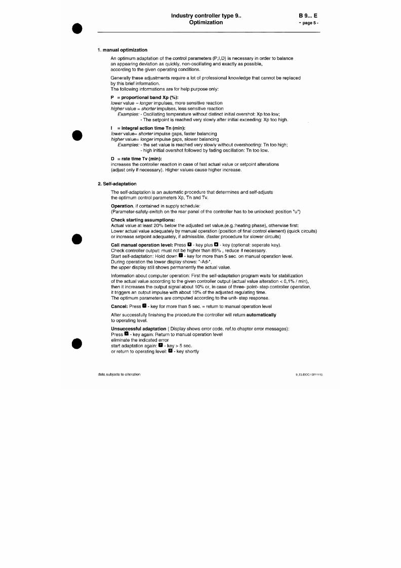
7/18/2019 M14 Thermal Fluid
http://slidepdf.com/reader/full/m14-thermal-fluid 275/486
/oi/vervalue= shorter impulse gaps, faster balancing
higherva\ue=
/onger impulse gaps, slower balancing
Examples: -
the set va lue is reached very slowly without overshooting: Tn too high;
- high initial overshot followed by fading oscillation: Tn too low.
D
=
rate time Tv (m in):
increases the controller reaction in case of fast actual value or setpoint alterations
(adjust only if necessary). Higher values cause higher increase.
2. Self-adaptation
The self-adaptation is an automatic procedure that determines and self-adjusts
Indus try con troller type KFM 9.
Configuration
B 9... E
- page 6 -
CodE
0
Cod I
/
ConF
ID I
Access from the operating level.
Unlock
the access first: Turn the switch on the rear panel of the controller to position "U"
(= unlocked). It Is no t possible to configure the controller with locked switch.
(Lock access after the adjustments: Switch position to "L"= locked)
Hold down the O - key and press the D - key,
hold down both keys for more than 5 sec. until the display changes
Enter the code number (password)
I1. . .D
(1...9999), factory setting: 1
move on
to next input: orieffy press D - key
Alternatively: Hold down key after entering code for more than 10 sec.
Possibility to modify code number (optional)
Select control function (type dependent): the displayed ID number for the configured
control function can b e changed by pressing the D - key:
-
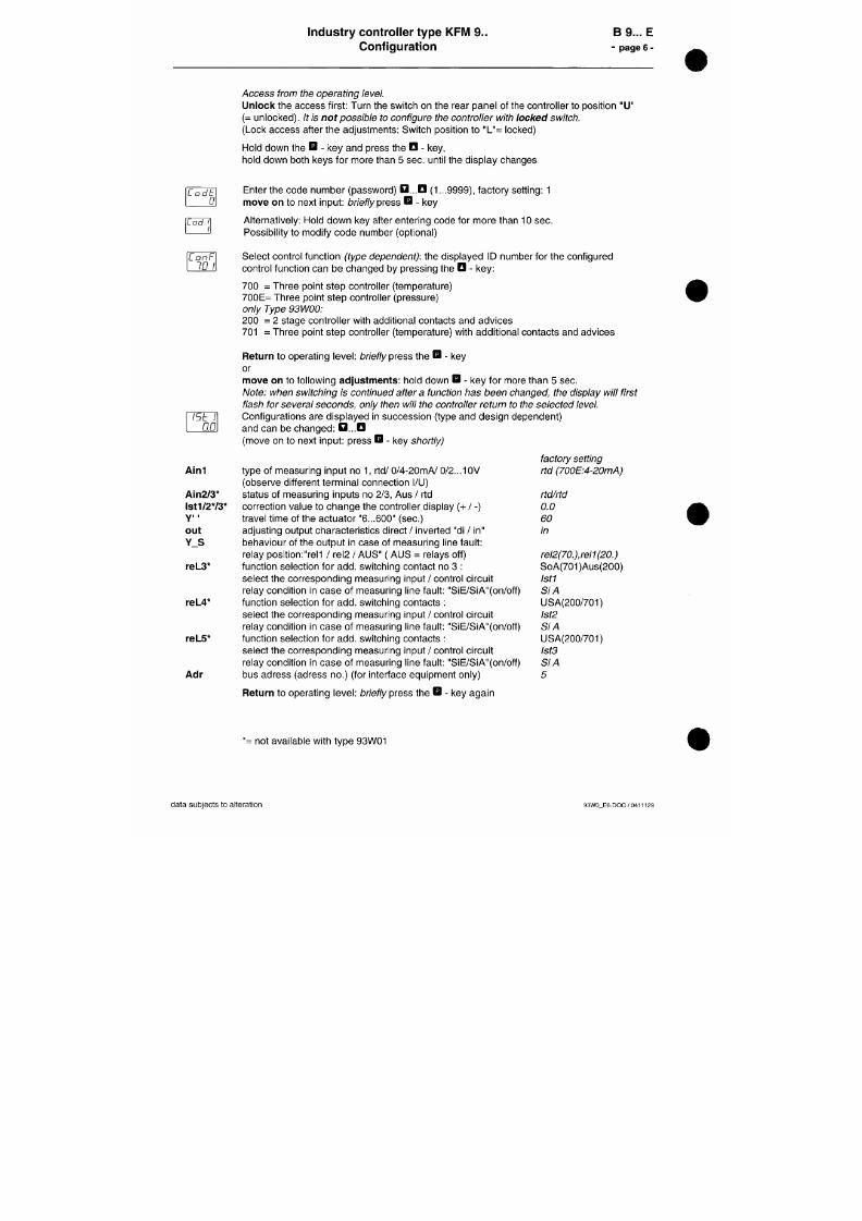
7/18/2019 M14 Thermal Fluid
http://slidepdf.com/reader/full/m14-thermal-fluid 276/486
700 Three point step controller (temperature)
700E= Three point step controller (pressure)
only Type 93W00:
200 = 2 stage controller with additional contacts and a dvices
701 = Three point step controller (temperature) with additiona l contac ts and advices
Return
to operating lev el: briefly press the
B
- key
or
move on to following adjustments: hold down Q - key for more than 5 sec.
Note: w hen switching is continued after a function has been changed, the display will first
flash for several seconds, only then w ill the controller return to the selected level.
Industrial controller type 9..
Facilities for Setting Supplementary Contacts
B 9... E
- page 7
-
Selectable switching functions
(depending on version):
For setting please refer to configuration leve l under „reL..'
Switching functions for trailing c ontacts :
LC A
Break contact on either side of setpoint
(Limit comparator). Relay drops out as
deviation increases (Aus = off)
LC E M ake contact on either side of setpoint
(Limit com parator). Relay picks up as
deviation increases (Ein = on)
Su
A Break contact below setpoint. Relay drops
out as actual value decreases (Aus
-
off)
Su
E M ake contact below setpoint. Relay picks
up as actual value decreases (Ein = on)
A Break contact above setpoint. Relay drops
off
1 x=r
off
on
of f
on
off
l Ä ^
X ^
S d ^
SA
W I
A -
1 TZI
A -
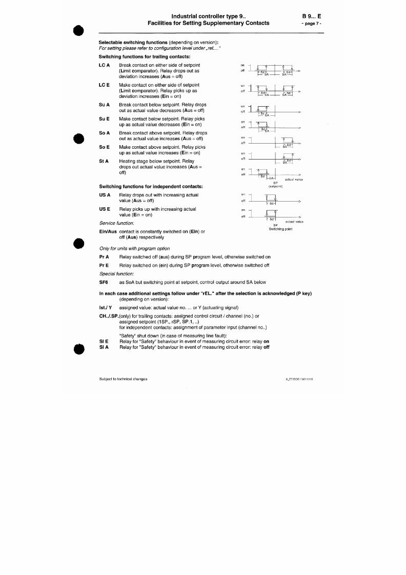
7/18/2019 M14 Thermal Fluid
http://slidepdf.com/reader/full/m14-thermal-fluid 277/486
So
out as actual value increases (Aus = off)
So E Make contact above setpoint. Relay picks
up as actual value increases (Ein
-
on)
St
A Heating stage below setpoint. Relay
drops out actual value increases
(Aus
=
off)
Switching functions for independent contacts:
US A
Relay drops out with increasing actual
on
off
on
off
o f f
T^,
1
^ÄHT
iZT
1 rg
^ d
u
actua l va l ue
S P
(se tpo in t )
Industry controller KFM 9.
Wiring diagrams
B9E
page 8 -
Wir ing d ia gram conf "2 00" (Type 93W00.. ): Example for co nne ct ing a 2 stage burner
A 927_W H I 0110118
controller electronics
measur ing input s
r iFuse:
[J230V:T0,1A
power supply relay outputs
LLL
99 10
JsM
11
1st? IsLa
^m^m'S
2 7
28 29
Rsl 1
5 0 5 l |
1 52
Bfil 2
53 54 55
Bel 3 Rfil 4
56 57158 59 6o|61
BaL
62
63 64
L N (é)
supply return exp. tank
(protect relay outputs by external fuse 2A)
fu l l l oad expan s ion
stage 1 s tage 2 unu sed i^^k tank high
Wir ing d iagram conf
" 7 0 1 "
(Type 93W00. . ): Example for co nne ct ing a m od . burner

7/18/2019 M14 Thermal Fluid
http://slidepdf.com/reader/full/m14-thermal-fluid 278/486
A927_WMl01101ie
controller electronics
mrarømR
1+
9 9
10 11
,
measur ing i r
St 1
1 2 3
•t]
4
i p u t s
St ?
5 6
^tJ
7
St 3
8 9
*
^
power supp l j
27 28 29
L N ®
/
Rel 1
5 0 5 l | 5 2
relay outputs
Re l ?
53 54 55
Rel 3
5 6 5 7 | 5 8
Rel 4
5 9 6 0 | 6 1
(p ro tec t re l ay ou tpu ts by ex te rna l f use ;
Rel f
62 63
A)
6 4
ful l load exp ans ion
i
AALBORG:;
I N D U S T R I E S
Aalborg Industries A/S
Gasvaerksvej 24
P 0 Box 844
9100 Aalborg
Denmark
CVR No. 17830635
Tel. +45 99 30 40 00
Fax +45 98 16 83 16
Telex 69705 albor dk
Giro No. 844-7756
VAT No. DK 17937677
E-mail: aal9aalborg-industries.dk
httpyAmvw.aalborg-lndustries.com
Bankers: Danske Bank A/S, Copenhagen
IBAN: DK 73 3000 3201 669138
Nordea A/S, Copenhagen
IBAN:
DK 30 2000 0270 344283
INSTRUCTIONS FOR SHELL & TUBE HEATER
Instruction Manual
for VESTA™ MX
Table of contents for instruction m anual
1. General Description 1
7/18/2019 M14 Thermal Fluid
http://slidepdf.com/reader/full/m14-thermal-fluid 279/486
2.
Installation Space Requirements 2
3.
Storage 3
4. Mounting and Installation 2
5. Connecting the Heat Exchanger 3
6. Operation 3
7. Conservation during shut down periods 4
8. Maintenance and Cleaning 4
INSTRUCTIONS FOR SHELL & TUBE HEATER
Safety valve, thermometer, and pressure gauge may be mounted on a standard
outlet tube (optional).
Regulating equipment for either oil, steam or water is optional.
All heaters have been hydrostatic pressure tested before delivery.
Vesta MX heat exchangers have been type approved by all major classification
societies.
2. Installation Space Requirements
2.1. Space allowance
When mounting the heater sufficient space must be allowed for withdrawal of
the tube insert for cleaning, inspection, or replacement purposes.
Please refer to dimensional drawing for withdrawal space requirements.
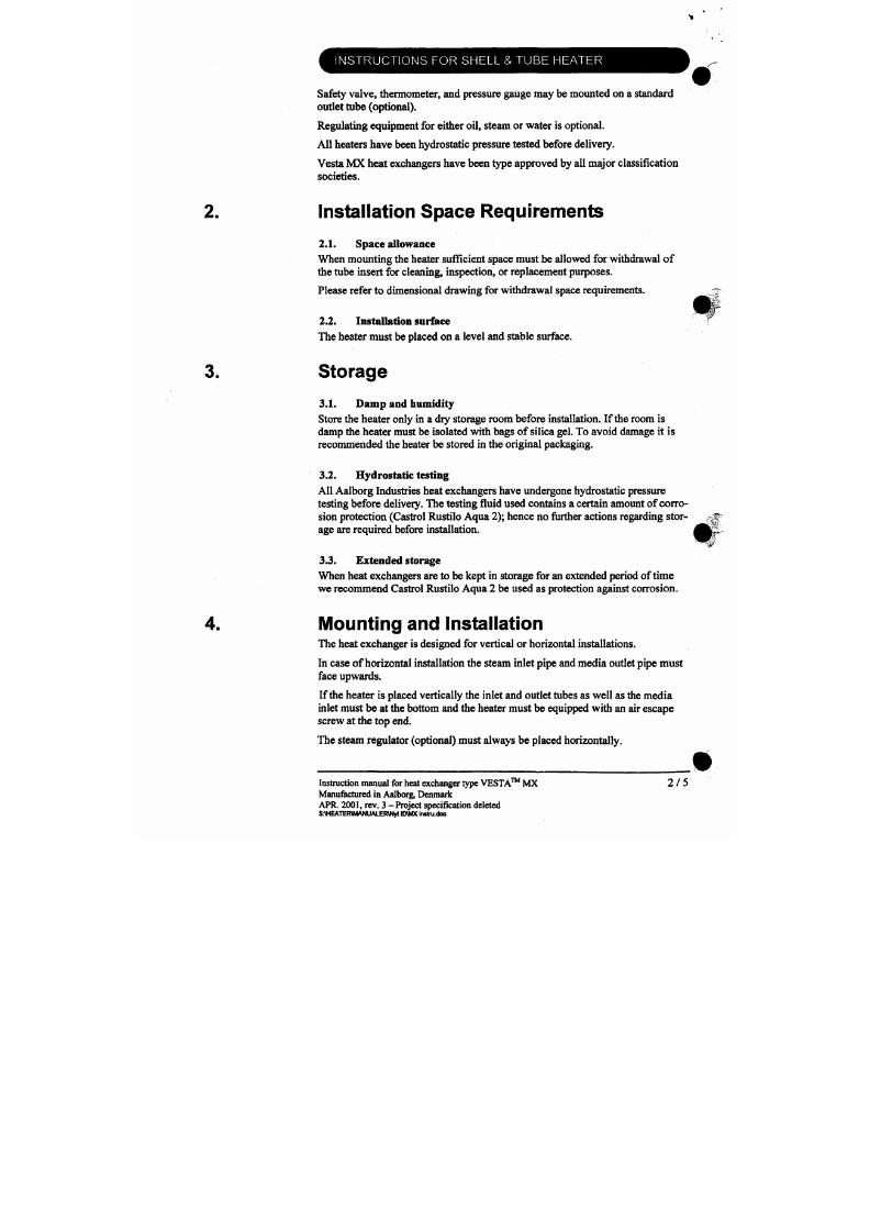
7/18/2019 M14 Thermal Fluid
http://slidepdf.com/reader/full/m14-thermal-fluid 280/486
2.2 . Installation surface
The heater must be placed on a level and stable surface.
3. Storage
3.1. Dam p and humidity
Store the heater only in a dry storage room before installation. If the room is
INSTRUCTIONS FOR SHELL & TUBE HEATER
The steam trap (optional) should be mounted as close to the condensate outlet as
possible and somewhat lower. The steam trap is always to b e placed horizon
tally.
Place the heater
on the
surface and drill the ho les for
the
foundation bolts. Place
the bolts into the holes and tighten up.
Connecting the Heat Exchanger
5.1.
Preparation and pipe connection of tlie heat exchanger
Remove all plugs and cover flanges before connecting the heater. Make sure
sand and other impurities are removed from all connections. Set up the pipe con
nections and make sure that no forces are transferred to the heat exchanger.
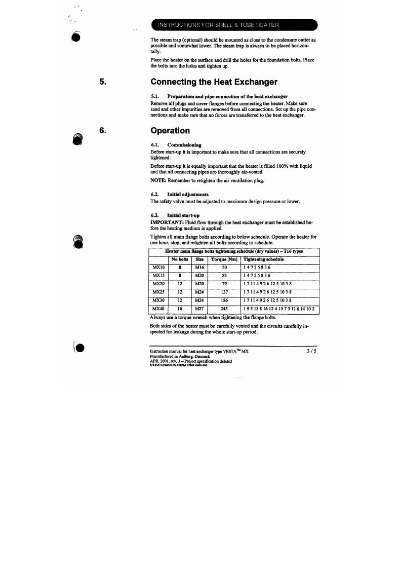
7/18/2019 M14 Thermal Fluid
http://slidepdf.com/reader/full/m14-thermal-fluid 281/486
Operation
6.1. Commissioning
Before start-up it is important to m ake sure that all connections are securely
tightened.
Before start-up it is equally important that the heater is filled
100%
with liquid
and that all connecting
pipes
are thoroughly air-vented.
NOTE: Remember
to
retighten th e air ventilation plug.
INSTRUCTIONS FOR SHELL & TUB E HEATER
6.4. Output
The output of the heater is subject to the supply of dry saturated steam at the in
let steam valve . The steam pressure applied to be as basis heater size calculation.
The output is furthermore subject
to
correct tj pe of steam trap be ing used. C or
rect layout of the condensate system avoids nega tive effect of counter pressure.
Conservation during shut down periods
Corrosion occurrences in shut down periods are mainly caused by oxygen. The
corrosion occurs if non-distilled or alkaline water remains in the heat exchanger.
However, even when fully emptied, heaters are exposed to corrosion caused by
water residues or condensation. Hence, heaters out of service should be protected
against corrosion.
If the heater is out of service for an extended period of time - in particular du ringwinter seasons with
frost
- it must be carefully em ptied. Open the air escape
^ ^
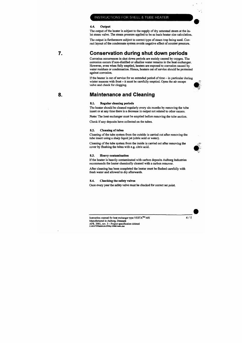
7/18/2019 M14 Thermal Fluid
http://slidepdf.com/reader/full/m14-thermal-fluid 282/486
valve and check for clogging.
f B ^
8. IVIaintenance and Cleaning
8.1. Regu lar cleaning periods
The heater should be cleaned regularly every six months by removing the tube
insert or at any time there is a decrease in output not related to other causes.
No te: The heat exchanger m ust be emptied before removing the tube section.
INSTRUCTIONS FOR SHELL & TUBE HEATER
Dismantling and reassembling of the tube
section
The tube section is inserted
into
the heater and fastened tightly between the shell
flange and the end flange. The back end o f the tube section is not fixed.
The steam connection for primary steam m ust
be
dismantled before dismantling
the tube section for inspection, cleaning, etc.
The
tube flange has threaded holes
for dismantling screws and for mounting eyebolts for lifting devices.
Gasket surfaces are to be cleaned and protected against damage. New gaskets are
to be fitted every time the flange connection has been dismantled.
IMPORTANT: Fluid flow through the heat exchanger must be established be
fore the heating medium is applied.
Tighten all mam flange bo lts according to below schedule. Operate the heater for
one hour, stop, and retighten a ll bolts according
to
schedule.
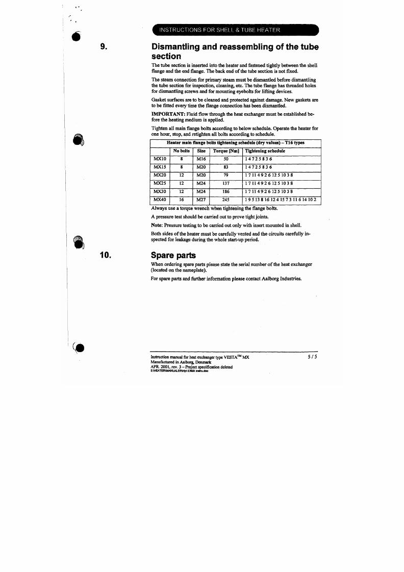
7/18/2019 M14 Thermal Fluid
http://slidepdf.com/reader/full/m14-thermal-fluid 283/486
Heater
main
flang e bolts tightening schedule (dry va lues) -
T16
types
MXIO
MX15
MX20
MX25
MX30
No bolts
8
8
12
12
12
Size
M16
M20
M20
M24
M24
Torque [Nm]
50
83
79
137
186
Tightening schedule
1 4 7 2 5 8 3 6
1 4 7 2 5 8 3 6
1 7 1 1 4 9 2 6 1 2 5 1 0 3 8
1 7 1 1 4 9 2 6 1 2 5 1 0 3 8
1 7 1 1 4 9 2 6 1 2 5 1 0 3 8
ucav.1 ipii ui
Type number changed
A 2S0900 \ JBL
Option I
•pt- 1^4
c q . . l
,1
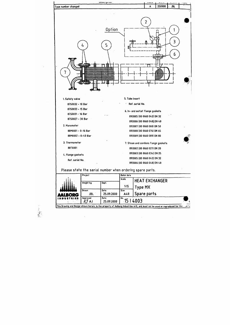
7/18/2019 M14 Thermal Fluid
http://slidepdf.com/reader/full/m14-thermal-fluid 284/486
1. Safefy valve
8750032 -10 Bar
875 0033 -15 B ar
5. Tube insert'
Ref. serial No.
T r a n s f e r G e a r P u m p s
O p e r a t i n g a n d M a i n t e n a n c e I n s t r u c t i o n s
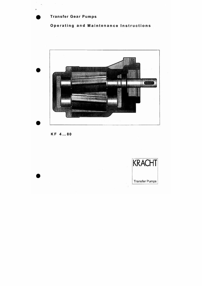
7/18/2019 M14 Thermal Fluid
http://slidepdf.com/reader/full/m14-thermal-fluid 285/486
L is t o f Conten ts
Safety
Safety Instruction Symbols
General Safety Instructions
Address of Manufacturer:
The D ocumentation
Description of Equipment
General
Specified Use
Construction
Technical Data
Explanation of Type Code
1
1
1
1
2
2
2
3
3
4
4
7/18/2019 M14 Thermal Fluid
http://slidepdf.com/reader/full/m14-thermal-fluid 286/486
General Data
Overview of Nominal sizes
Overview of Materials
Overview of Operating Pressures
Pump installation and removal
Mechanical Installation
5
5
6
6
6
6
Safety
Safety Instruction Symbols
The safety notes contained in these ope rating instructions are iden tified by the following warning sym
bol.
A
If these warnings are not heeded , the consequence can be danger to life and limb and damage to
equipment..
Other notes, which do not w arn of danger, but which provide tips for optimum operation, are symbo
lised by a hand.
7/18/2019 M14 Thermal Fluid
http://slidepdf.com/reader/full/m14-thermal-fluid 287/486
A
General Safety Instructions
The operat ing safe ty of the pump suppl ied is only guaranteed i f the pump is
us e d a s s pe c i f i e d (s e e "D e s c r i p t i on o f e qu i pme nt " ) . The s ta te d l i m i t i ng v a l ue s
(see "Technica l data" ) must not b .e exceeded under any c i rcumstances .
Personnel hav ing the responsibi l i ty for ins ta l l ing, operat ing or repa i r ing the
pump mus t pos s e s s the a ppr opr i a te qua l i f i c a t i ons ; the s e ma y ha v e be e n ob
ta i ne d th r ough t r a i n i ng or a ppr opr i a te i ns t r uc t i on . S uc h pe r s onne l mus t be
fa mi l i a r w i th the c onte n ts o f the s e ope r a t i ng i ns t r uc t i ons .
The Documentat ion
Thes e operating instructions des cribe the installation, the operation and the repair of
the
KRACHT
KF 4...80 tranfer gear pump.
The equipment is manufactured in various versions. The specific version can be identified from the
type label affixed to the pump. The format of the type designation and a detailed description of the
individual versions and nominal sizes is to be found in the "Technical da ta" section (see "Description of
equipment").
Descr ipt ion of Equipment
General
KRACHT pumps in the KF Series are outside gear wheel pumps, which operate according to the dis
placement principle. Two gear wheels which are rotating in mesh with each other cause an increase in
volume to occur as the spaces between the gear wheels are exposed at the pump inlet (suction side),
so that the medium can flow into the pump. Simultaneously, a corresponding volume is displaced at the
pump outlet (pressure side) through rotation of the gear teeth into the filled area va cated by the prece
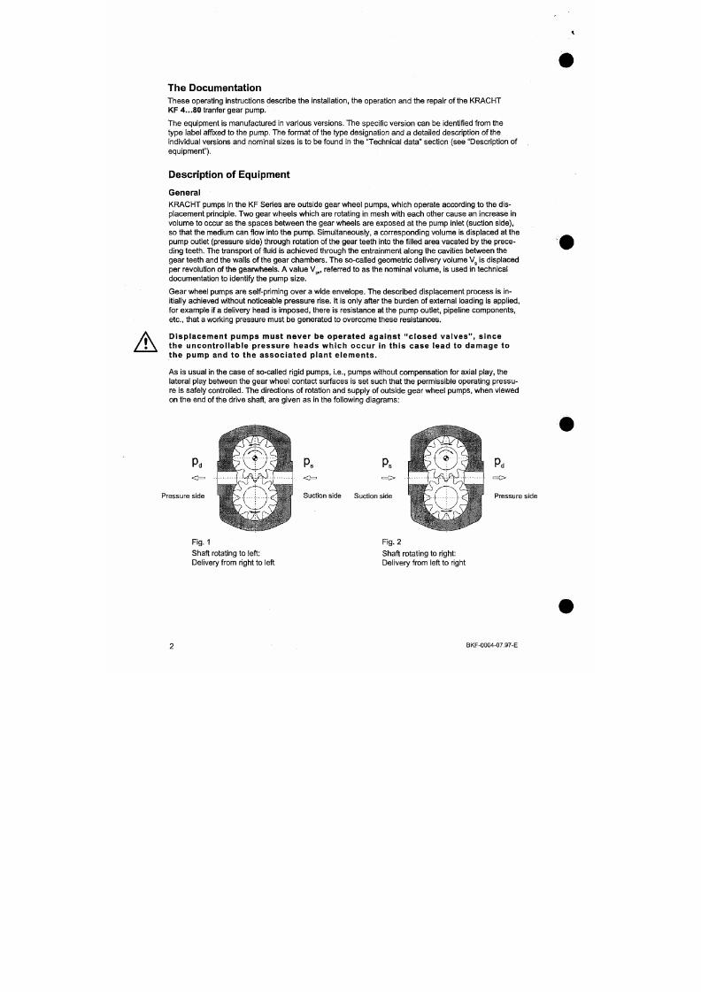
7/18/2019 M14 Thermal Fluid
http://slidepdf.com/reader/full/m14-thermal-fluid 288/486
ding teeth. The transport o f fluid is ach ieved through the entrainment a long the cavities between the
gear teeth and the walls of the gear cham bers. The so-called ge ometric delivery volum e V^ is displaced
per revolution of the gearwheels. A value
Vg„,
referred to as the nom inal volume , is used in technical
documentation to identify the pump size.
Gear wheel pumps are self-priming over a wide envelope. The described displacement process is in
itially achieved w ithout noticeable p ressure rise. It is only after the burde n of external loading is applied,
for example if
a
delivery head is impos ed, there is resistance at the pum p outlet, pipeline com ponents,
etc., that a working pressure must be generated to overcome these resistances.
D i s p l a c e me nt pumps mus t ne v e r be ope r a te d a ga i ns t "c l os e d v a l v e s " , s i nc e
Specified Use
The KF is a pump for the continuous delivery of fluids. The different types of seals available enable the
pump to be used for various media.
It must be ascertained that the m edium to be delivered is compatible with the materials used in the
construction of the pump (see "Technical data").
The maximum perm issible op erating data given in the "Technical data" section m ust be unconditionally
adhered to.
Construction
The drawing below illustrates the principle features of the KF pump.
8
1
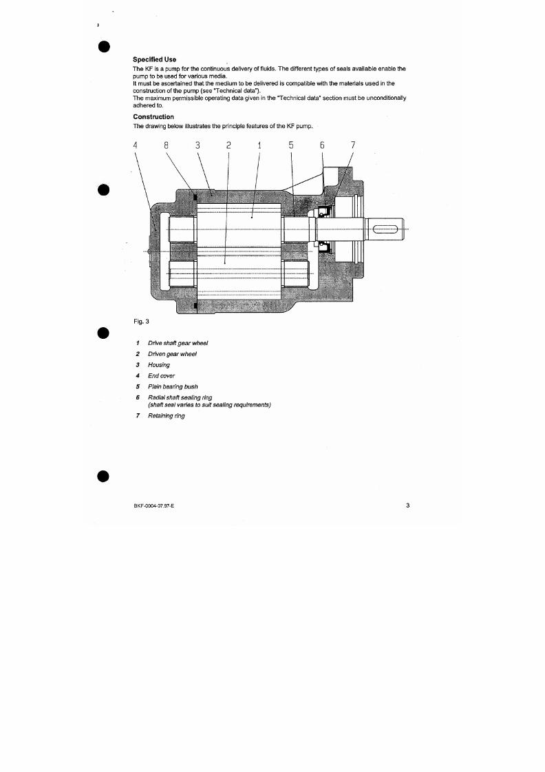
7/18/2019 M14 Thermal Fluid
http://slidepdf.com/reader/full/m14-thermal-fluid 289/486
Tec hnical Data
Explanation of Type Code
Example:
Product name
K F
Nominal size
V g = 4 / 5 / 6 , 3 / 8 / 1 0 / 1 2 , 5
1 6 / 2 0 / 2 5 c m ^
V g = 3 2 / 4 0 / 5 0 / 6 3 / 8 0 c m ^
4 0
Direction of rotation
R
= right
L = left
D 1 5
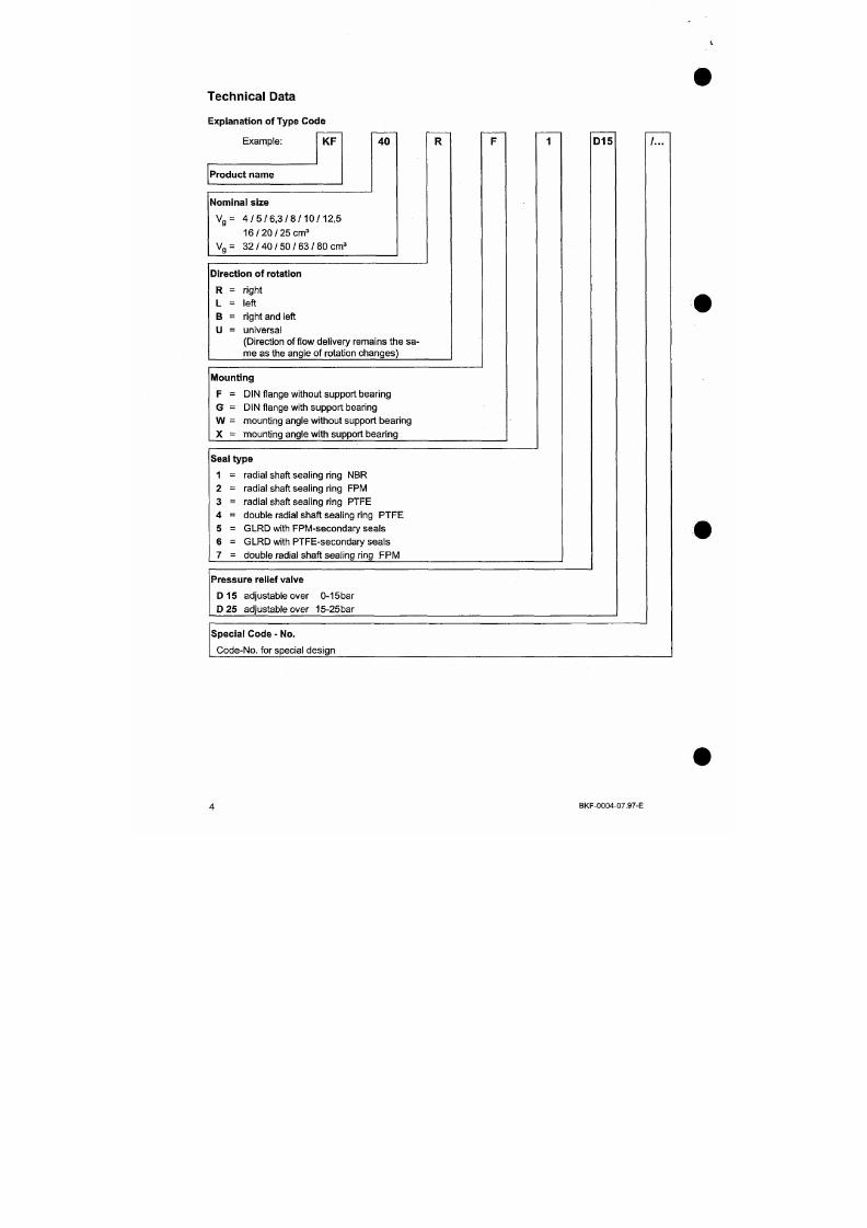
7/18/2019 M14 Thermal Fluid
http://slidepdf.com/reader/full/m14-thermal-fluid 290/486
B = right and left
U = universal
(Direction of flow delivery remains th e sa-
rnea s the angle of rotation changes)
Mounting
F
= DIN flange without support bearing
G = DIN flange with support bearing
General Data
Type of construction
Materials
Type of mounting
Drive siiaft end
Pipe line connection
installed attitude
Viscosity
Ambient temperature
Filtering
min
V
max
u mm
Umax
External gear pump
see "M aterials" overview
Flange DIN ISO 3019
ISO R 775 short/cylindrical
KF 4 to 25 Whitworth - pipe thread
KF 32 to 80 SAE - flange connection
Arbitrary*
12 mm^/s
20000 mm%
-20
'C
60 "C
Filter fineness < 60 pm
*
With exception of universal version
(KF.
..U...)
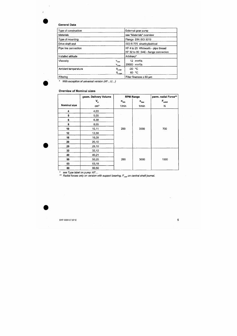
7/18/2019 M14 Thermal Fluid
http://slidepdf.com/reader/full/m14-thermal-fluid 291/486
Overview of Nominal sizes
Nominal size
4
geom. Delivery Volume
cm^
4,03
RPMF
" m l n
1/min
tange
max
1/min
perm, radial Force**
'^radial
N
Overview of Materials
Type of
seal*
1
2
3
4
5
6
7
Housing /
Cover
GG25
Gear
Carburising
steel
(1.7139)
Bearing
P 1 0
Shaft se als
NBR
FPM
PTFE
PTFE
Carbonaceous (in synthetic resin),
CrMo-Guß.FKM,
1.4571
SiC-Si,FFKM,
1.4571
FPM
O-Ring
NBR
FPM
FEP
FEP
FP
FEP
FPM
*
se e
Type
label on pum p: KF...
Overview of Operating Pressures
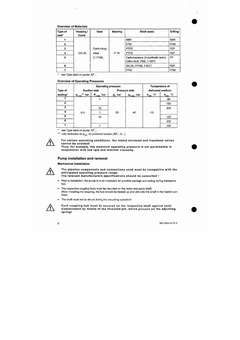
7/18/2019 M14 Thermal Fluid
http://slidepdf.com/reader/full/m14-thermal-fluid 292/486
Type of
sealing*
1
2
3
4
Suctio
Pemin** bar
-0,4
Operatinc
n side
P
bar
e max
1
10
1
pressure
Pressu
Pb
bar
25
re side
Pbn,3x bar
40
Temper
deliverec
1
, °C
-10
ature of
medium
max
90
150
200
• Al ignment of the Cou pl ing
When installing the coup ling, care should be taken that the dimens ion E is precisely maintained, so
that during operation the coup ling is free to move axially. In order that the e lastic toothed rim is not
exposed to pressure on its fac e, for axial movement, the dimension "E " is to be taken as a mini
mum.
Shaft with adjuster spring
sits in toothed rim ( d j
haft separation "E "
r
1
•
- ^
J
. 1 .
rn
E
• K
1
•m?i^^
S
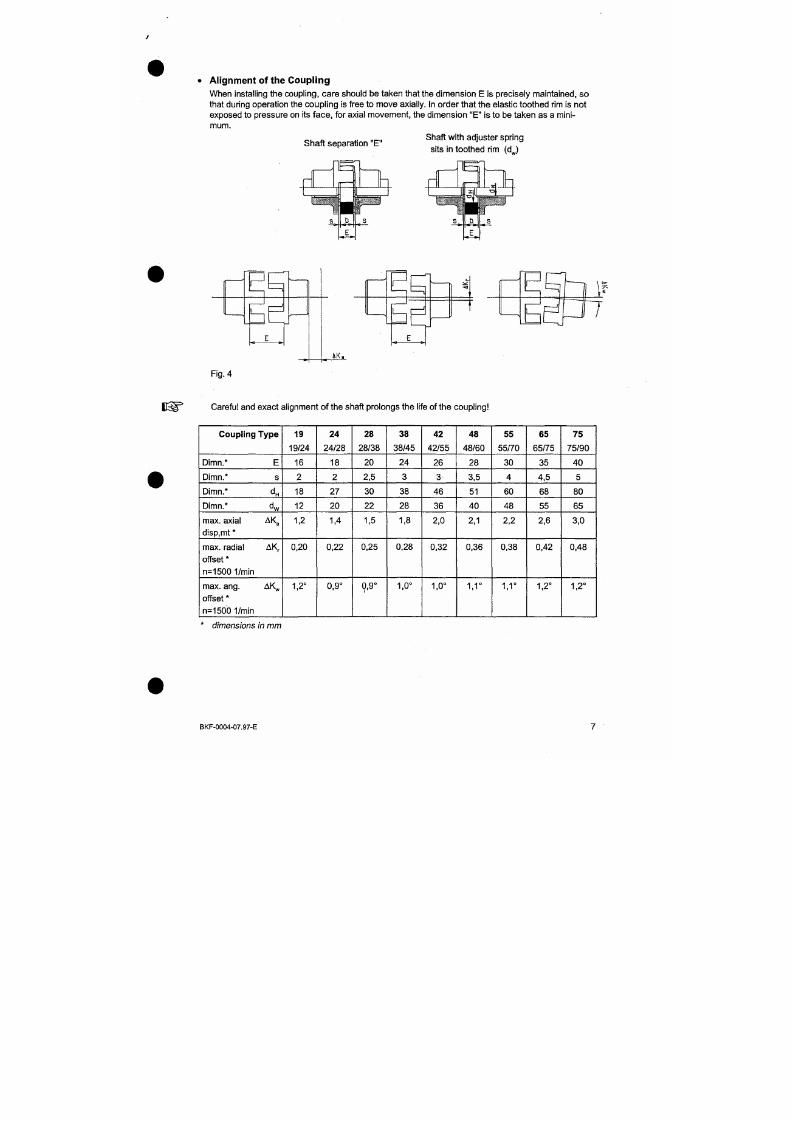
7/18/2019 M14 Thermal Fluid
http://slidepdf.com/reader/full/m14-thermal-fluid 293/486
Fig. 4
iKa
A
The given permissible misalignment values for the couplings represent general guidelines which ta
ke the loading of the cou pling into consideration up to the n ominal torque T| ,an operating rpm
n = 1500 and an ambient temperature o f +30°C. For operating conditions outs ide these limits,
KRACHT GmbH should be consulted.
The misalignment values a re individually applicable, in the ca se of a simultaneous o ccurrence they
should be applied proportionately.
The couplings can either take up a radial or an angular m isalignment.
If
the
shaft clearance dim ension is less than the coupling d imension "E", then one of
the
shaft ends
can extend into the toothed rim section. The dimension "d„" corresponds to the maximum shaft
diameter which, with the adjuster spring, is allowed to pene trate into the toothed rim, dimension "d„".
If it is possible to remove th e adjuster
spring,
i.e., only the sha ft penetrates into the toothed rim sec
tion, then the shaft dimension can be increased to up to 2 mm less than the given dimension "dH",
so that the axial freedom of m ovement of the toothed rim is no t restricted.
Rotat ing par ts must be protected by the customer aga inst unintent iona l c o n
t a c t
• Mount the pump on the pump supports or feet.
• Before installing the pump, clean the pipework, removing dirt, sand,
swarf,
etc. Welded pipes, in
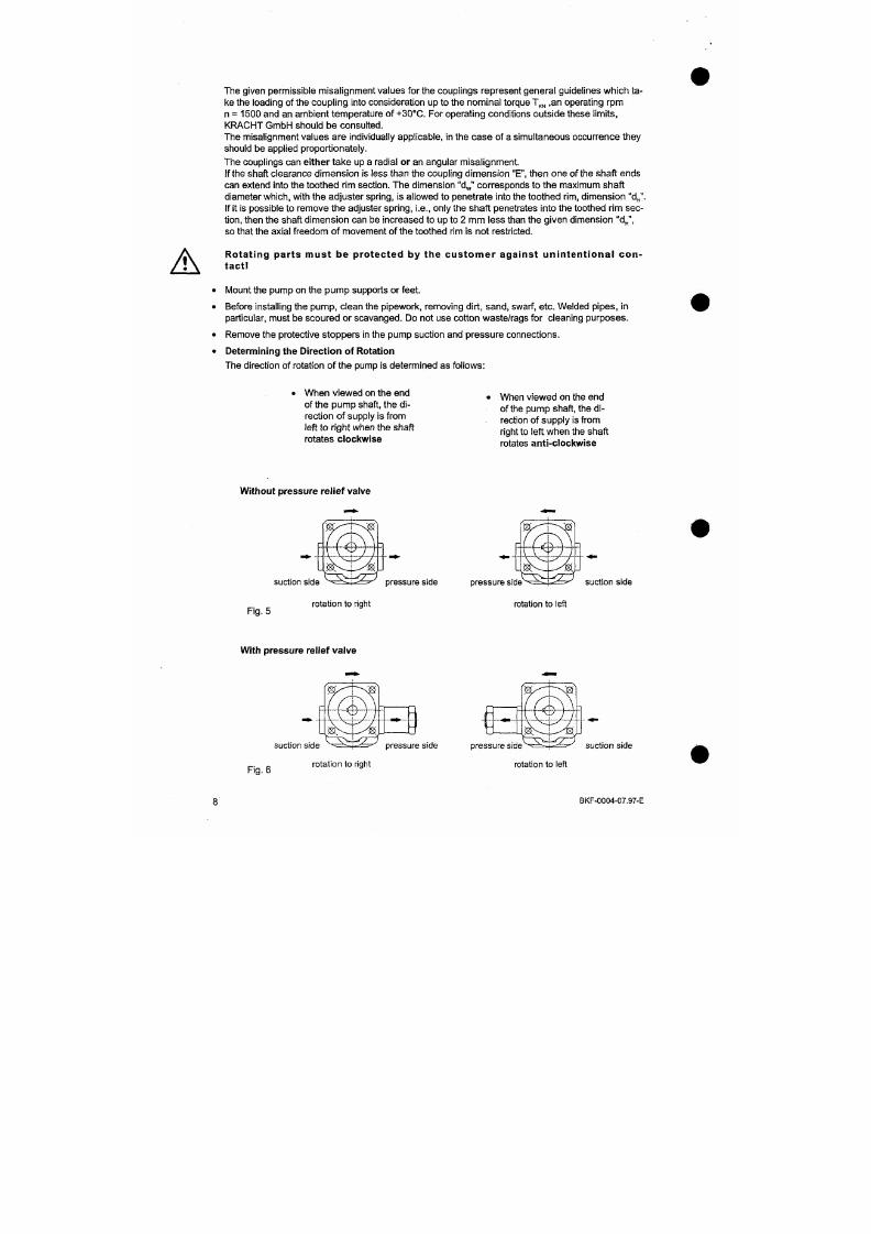
7/18/2019 M14 Thermal Fluid
http://slidepdf.com/reader/full/m14-thermal-fluid 294/486
particular, must be scoure d or scavange d. Do not use cotton waste/rags for cleaning purposes .
• Remove the protective stoppe rs in the pump suction and press ure connections.
• Determining the Direction of Rotation
The direction of rotation of the pump is determined as follows :
When viewed on the end
of the pum p shaft, the di
rection of supply is from
When viewed on the end
of the pump shaft, the di
rection of supply is from
• Suction P ipework
Provision of the suction pipework should be carried out with great
care,
since the operational beha
viour of the pump is greatly affected by this factor.
The suction pipe should be as short and as straight as possible. Additional sources of pipeline
resi
stance, such as formed parts and valves, should be avoided.
The reduced pressure in the suction pipe depends on the sum of all the resistances in the suction
line and the suction head, taking account of the data specific to the m edium in the line.
The suction can be checked by installing a vacuum meter on the pump/suction connection.
The permissible pressure at the pump inlet must not fail below the value p , „,„ given in the "Techn i
cal data" sec tion.
The only exception to this is the start-up condition of the pump , when a pressure of - 0.6 bar (suc
tion) is tolerable for up to 30 m inutes.
The nominal diameter of the suction line can be chosen to be considerably larger than that of the
pump connection.
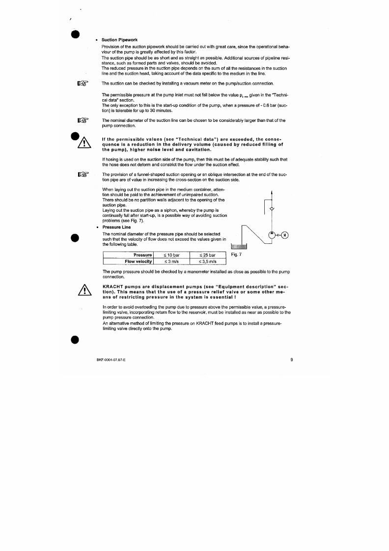
7/18/2019 M14 Thermal Fluid
http://slidepdf.com/reader/full/m14-thermal-fluid 295/486
'A
I f t h e p erm iss ib le va lu es ( see "T ech n ica l d a t a" ) a re exceed ed , t h e co n se
quence is a reduct ion in the del ivery vo lume (caused by reduced f i l l ing of
the pump) , h igher no ise level and cavi tat ion .
If hosing is used on the suction side of the pump , then this must be of adequate stability such that
the hose does not deform and constrict the flow under the suction effect.
The provision of a funnel-shaped suction opening or an oblique intersection at the end of
the
suc
tion pipe are of value in increasing the cross-section on the suction side.
When operating a pump which is to feed, via a non-return valve, into a circuit which is under pres
sure (e.g. reserve pump in a lubrication circuit), suction difficulties can occur if the suction line is
fil
led with air. In these cases, the pressure line should be vented directly before the non-return valve.
This can be achieved, for example, by fitting a venting jet in the circuit (Fig. 8), or by providing a re
stricted by-pass (Fig. 9).
V
p^
V ^
) (
) (
^
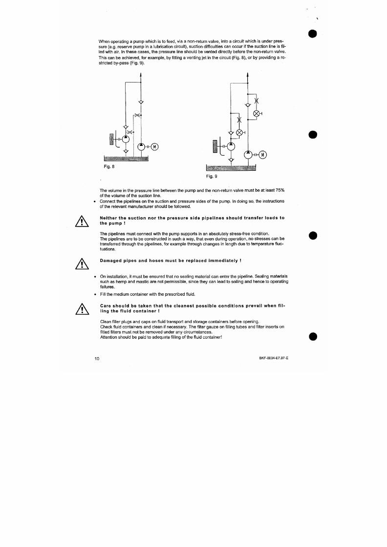
7/18/2019 M14 Thermal Fluid
http://slidepdf.com/reader/full/m14-thermal-fluid 296/486
'?,
M)
Fig.
8
?
Fig.
9
Y
?,
M)
A
In order to achieve optimum noise protection, it is recommended tha t an anti-vibration flange is fitted
between the pump and the pump supports and that damping elements are inserted b etween the elec
tric m otor and the installation.
Likewise, the use of suction and pressure hoses reduces the noise level of
an
hydraulic installation.
Pump Removal
The cleanest possible conditions should be assured during all work. Prior to loosening screwed
con
nections, their external surroundings should be cleaned.
Dur ing a l l work on the pump and pr ior to removal , the connect ing pipework
mus t be de pr e s s ur i s e d a nd the motor i s o l a te d
In addi t ion, precaut ions must be taken to ensure that the motor cannot run-up
dur ing work on the pump.
• Remove the depressurised pipelines from the pum p.
Leakages of dangerous media must be col lec ted and disposed of in such a way
that no danger resul ts to personnel or to the env i ronment . In so doing, the s ta
7/18/2019 M14 Thermal Fluid
http://slidepdf.com/reader/full/m14-thermal-fluid 297/486
^
tu tor y r e gu l a t i ons mus t be obs e r v e d . .
• Secure the pump connections and pipelines against the ingress of dirt.
Commissioning
Commiss ioning is only to be carr ied out by appropr ia te ly t ra ined and qua l i f ied
personnel . Pr ior to s tar t ing up plant , i t must be ascer ta ined that an adequate
quant i ty of the operat ing medium is ava i lable , in order to avoid dry running.
A
• Special feature on sealing variants 4 and 7 (Double radial shaft sealing ring)
• The sealing chamber (see F ig. 10) must be filled with a
suitable barrier medium prior to initial operation of the
pump.
B e for e c ommi s s i on i ng , the s e a l i ng
chamber must be f i l led wi th a barr ie r me
dium. .
Sealing chamber
The pumps should be started up at either very low or zero pressure
loading.
The existing shut-off devices should be fully opened and
the pressure relief
valve,
installed in the pressure line, should be
adjusted to the lowest opening pressure setting.
Pressure setting of the pressure relief valve
Fig. 10
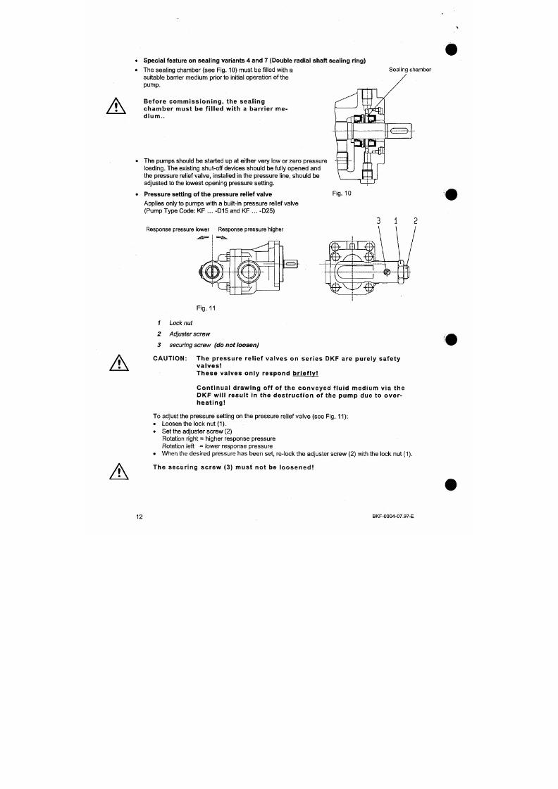
7/18/2019 M14 Thermal Fluid
http://slidepdf.com/reader/full/m14-thermal-fluid 298/486
Applies only to pumps w ith a built-in pressu re relief valve
(Pump Type Code: KF ... -D15 and KF ... -D25)
Response pressure lower Response pressure higher
start-up is achieved by repeated rapid switching on and off of the drive motor (inching mode), wi
thout reaching full rpm, until it is apparent that the pump is operating satisfactorily. The satisfactory
operation being detectable either from manometer readings, or from the noise generated by the
pump, and being achieved over a period of not longer than 30 seconds . This particularly applies
when a cold pum p must be started-up w ith a fluid medium that has already been warmed , in order
to achieve a slow heating up of the pump and to prevent jamming of the pump due to heat shock.
After switching on the motor, it is then allowed to run for a few m inutes , under zero or low pressure.
The pressure loading can then be increased in stages until the desired operating pressure is re
ached.
• On attaining the required operating values, the tempe rature of the medium and of the pump should
be checked. The control points on the pump are the shaft bearing positions and the shaft seals. The
temperatures reached on the surface of the pump housing should be approx. 10°C greater than the
temperature of the medium.
• After several hours of running time, the final operating temperature shou ld be checked (for maxi
mum temperatures, see the section on "Technical data").
Maintenance
Assuming correct installation in accordance with the conditions of use and correct
operation,
KRACHT
7/18/2019 M14 Thermal Fluid
http://slidepdf.com/reader/full/m14-thermal-fluid 299/486
gear pumps are of such construction tha t a long and fault-free operational life should be obtained. The y
require a minimum of maintenance which, however, is necessary for reliable operation, since experi
ence has shown that a high percentage of the faults and damage which can occur are attributable to
the ingress of dirt and inadequate maintenance. The extent of servicing required and the service and
inspection intervals are, in general, laid down by the m anufacturer in an app ropriate plan.
The regular examination of
all
operating data, such as pressure, temperature, current consumption,
degree of filter soiling, etc., contributes to the early detection of potential failure.
Changing the direction o f rotation of the pump
On pump types K F... R.. . and K F...L ... , i.e. pure left or right rotating pumps , a change in the direc
tion of rotation is only possible by re-building the pump.
cover
fixing
scews
cover fixing scews
cover
fixing
scews cover
fixing
scews
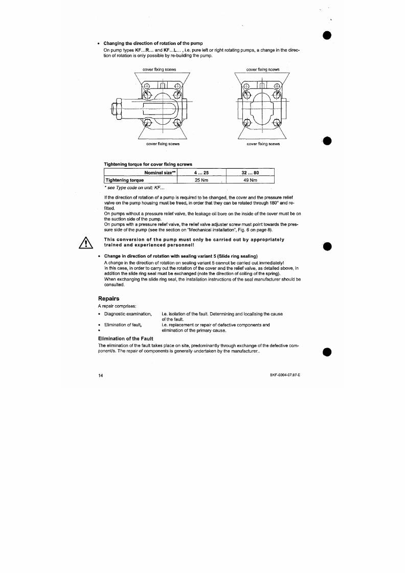
7/18/2019 M14 Thermal Fluid
http://slidepdf.com/reader/full/m14-thermal-fluid 300/486
Tightening torque for co ver fixing
Nominal size**
Tightening torque
screws
4 . „ 2 5
25 Nm
32
. ..
80
49 Nm
*
see Type code on unit: KF...
A
Repai rs must only be carr ied out by t ra ined spec ia l is t personnel .
Given the appropriate know-how and adequate equipment, the repa ir may also be carried out by the
end user or the initial equipper. Assistance in this is available in the form of spares lists and repair
instructions.
Diagnosis
Lack of adequate sealing is a freque nt source of failure. If this occurs at the pipeline connec tions, it
may be eliminated by simply tightening the screwe d fittings.
In the case of a lack of sealing o n the pump, the respective seals m ust be replaced (see spares list).
Detection and Elimination of Faults
The following list gives the causes of faults which are most frequently encountered during operational
failures together with an indication of the problem areas to be rectified.
In the event of the occurrence o f a fault which canno t be iden tified, please request assistance from
KRACHT.
Fault P ossible cause
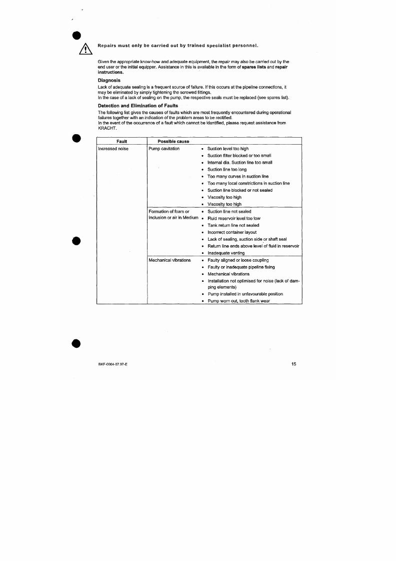
7/18/2019 M14 Thermal Fluid
http://slidepdf.com/reader/full/m14-thermal-fluid 301/486
Increased noise
Pump cavitation • Suction level too high
> Suction filter blocked or too small
> Internal dia. Suction line too small
> Suction line too long
• Too many curves in suction line
> Too many local constrictions in suction line
> Suction line blocked or not sealed
Fault
Pump does not suck
Insufficient supply flow
Possible cause
•
•
•
•
•
Fluid level in reservoir too low
Incorrect direction of rotation
Throttling element in suction line
Foreign body in suction line
Volume of the pressure linebetween pum p and
non-return valve too sm all, pump cannot com
press the air found in the suction line into the
pressure line
Non-return valve in the pressure line not vented
Throttling element in suction line
> Fluid leve l in reservoir too low
> Suction filter blocked or too small
> Viscosity too high
' Rpm too high
> Pressure too high
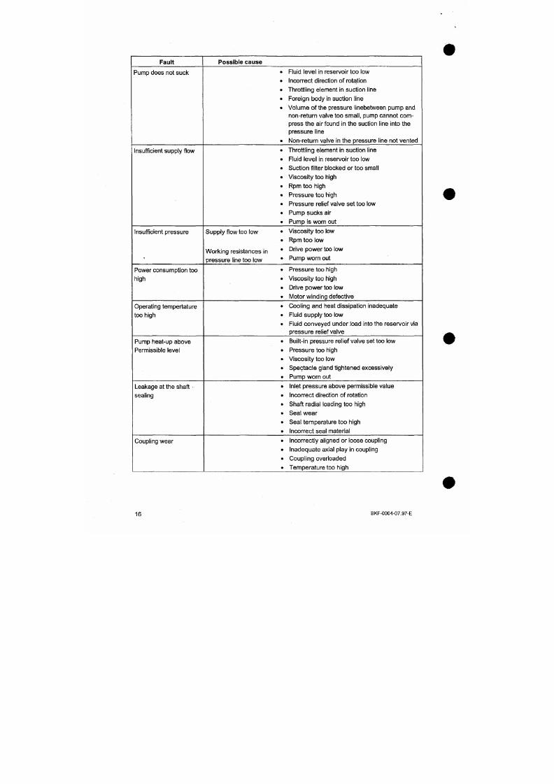
7/18/2019 M14 Thermal Fluid
http://slidepdf.com/reader/full/m14-thermal-fluid 302/486
Insufficient pressure Supply flow too low «
Working resistances In '
pressu re line too low '
• Pressure relief valve set too low
> Pump sucks air
> Pump is worn out
> Viscosity too low
» Rpm too low
» Drive power too low
» Pump worn out
f • • • • •
il{ll{lti
I l^^^k R I E S
Aalbo rg Industries NL BV
P o Box 145
3200 AC Spijkenisse
Ohmweg 8
3208 KE Spijkenisse
The Netherlands
Tel. +31 181 650 500
Fax +31 181 650 501
Traderegister Rotterdam
No .
24234179
VAT No. NL0081.91.694.B.01
E-mail: [email protected]
http://www.aalborg-industries.com
Bankers: Rabobank, Hoogvliet
Account No. 32.95.68.094
Swift-address: RABONL2Ü
153
Oil Burner Controls
LAL...
Series 0 2
ISO 9001
C€
Supplementarv data sheets 7713 and 77 14
7/18/2019 M14 Thermal Fluid
http://slidepdf.com/reader/full/m14-thermal-fluid 303/486
Oil burner controls designed for use with atomizing expanding flame burners of
medium to high capacity (intermittent operation*) with air checic supervision for
supervised air damper control. Flame supervision with photoresistive detector
QRB..., blue flame detector QRC1... or selenium photocell detector RAR...
The oil burner controls are tested and certified in accordance with EN 230. They
carry the CE mark in compliance with the directives on electromagnetic
compatibility.
M o d e o f o p e r a t i o n
A
A-B
B-C
C
C-D
Prerequisites for
burner
start-up
The diagrams above show both the connections and the control program of the
permissible or required input signals to the control section of the bumer control as well
as to their flame supervision circuit. If the required input signals are not present, the
burner control interrupts the start-up seque nce at the points m arked by the sym bols and
initiates lockout w here this is required b y the safety regulations. The sym bols used are
identical to those on the bumer control's lockout indicator.
Start comm and (e.g. given by the control thermostat or pressurestat R of the installation)
Start-up sequence
Burner operation (according to the control commands given by load controller LR)
Controlled shutdown through R
Sequence switch runs into start position A , post-purge
During burner off periods the flame supe rvision circuit is under voltage, in order to carry
out the detector and extraneous light test.
- Burner control not interiocked in lockout position
- Sequen ce switch in start position (with
LAL1...
indicated by voltage on terminals 4
an d
11 ;
with LAI_2... indicated by vo ltage on temninals
11
and 12)
- Air damper closed. Limit switch zfo r th e CLOSED position must feed voltage from
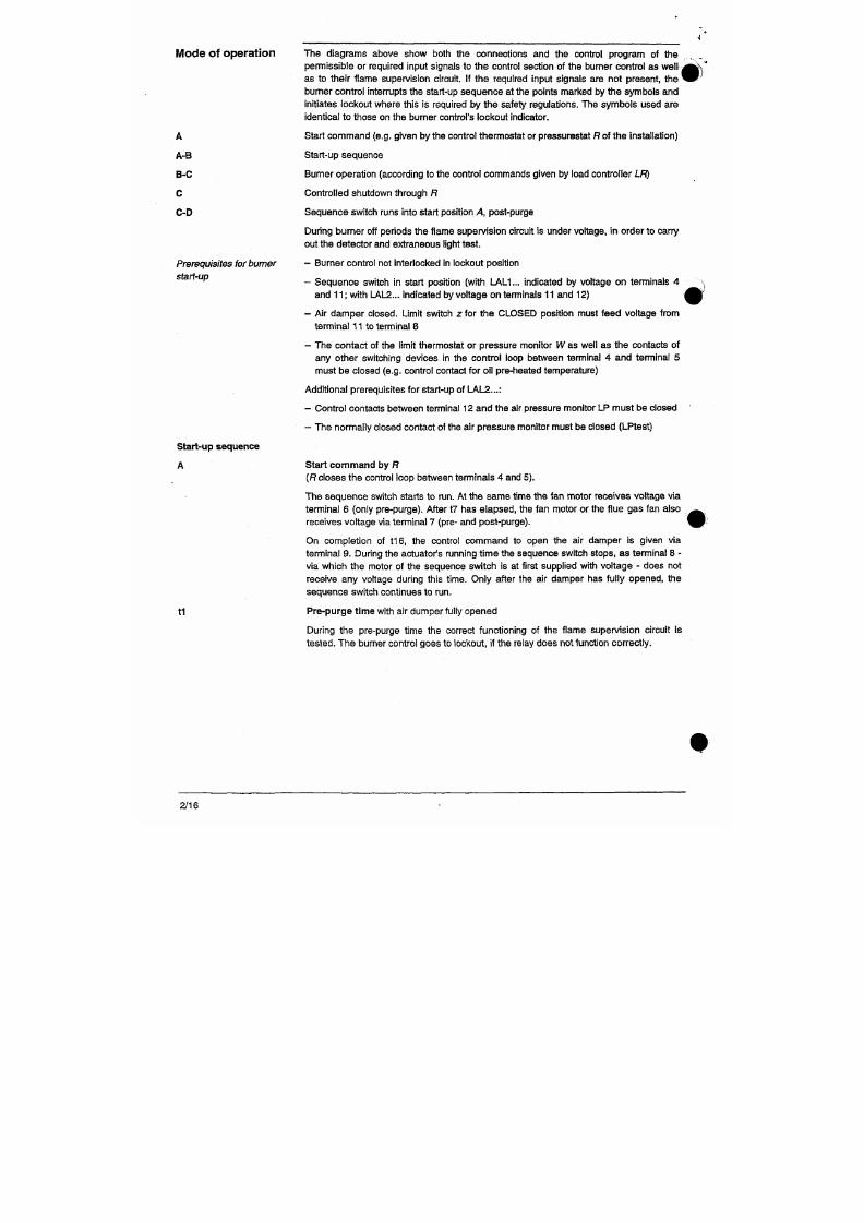
7/18/2019 M14 Thermal Fluid
http://slidepdf.com/reader/full/m14-thermal-fluid 304/486
terminal 11 to terminal 8
- The con tact of the limit thermostat or pressure monitor W as well as the contacts of
any other switching devices in the control loop between terminal 4 and terminal 5
must be closed (e.g. control contact for oil pre-heated temperature)
Additional prerequisites for start-up of LAL2...:
- Control contacts between temninal 12 and the air pressure monitor LP must be closed
*
With LA L2...:
Shortly after the beginning of the pre-pu rge time , the air pressure monitor must change
over from terminal 13 to terminal 14, as otherwise the bumer control initiates lockout
(start of air pressure check).
t3 '
Long pre-ignition time
(Ignition transformer connected to term inal 15)
With the LAL1... bumer controls the ignition transformer is switched on with the start
command;
with the LAL2... types only when the air pressure monitor LP has changed
over, that is on completion of tlO a t the latest.
After completion of the pre-purge time, the burner control drives the air damper via
tenminal 10 into the low flame position which is determined by the changeover point of
auxiliary switch m. During the running time the sequence switch stops until terminal 8
receives voltage via
m .
Then the m otor of the seq uence switch is switched to the control
section of the bumer control. Hence, from now on control signals to terminal 8 do not
affect the further start-up of the burner and the subsequent bumer operation.
t3 Sho rt pre-ignition time,
provided Z i s connected to terminal 16; then release of fuel at
terminal 18.
t2 Safety time
On completion of the safety time, a flame signal m ust be present at terminal 22. It must
be present until controlled shutdown takes place, otherwise the burner control initiates
lockout and interiocks itself in lockout position.
tSn P re-ignition time ,
provided the ignition transformer is connected to terminal 15. With
short pre-ignition (connection to terminal 16), it remains switched on only up to the endof the safety time .
t4 interval. On completion of t4, terminal 19 is under voltage. Thus the fuel valve at
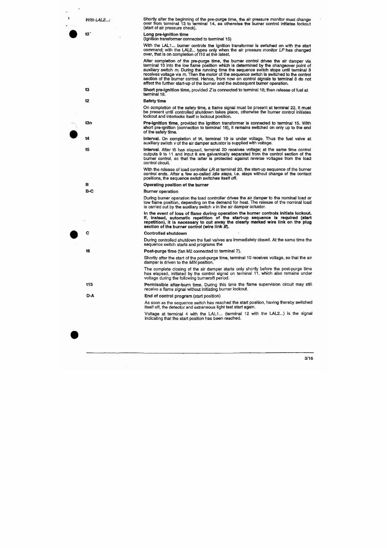
7/18/2019 M14 Thermal Fluid
http://slidepdf.com/reader/full/m14-thermal-fluid 305/486
auxiliary switch vo f the air damper actuator is supplied with voltage.
t5 Interval. After ts has elapsed, terminal 20 receives voltage; at the same time control
outputs 9 to 11 and input 8 are galvanically separated from the control section of the
bumer control, so that the latter is protected against reverse voltages from the load
control c ircuit.
W ith the release of load controller LR at terminal 2 0, the start-up sequence of the burner
control ends. After a few so-called idle steps, i.e. steps without change of the contact
positions, the sequence switch switches itself off.
B Operating position of the burner
Funct ions
With
regard to
standards
With
regard to the
control of the burner
The following LAL... features exceed the standards, thus offering a high level of
additional safety:
- Detector and extraneous light test are restarted imm ediately after the tolerate d after-
burn time. This means that open or not fully closed fuel valves initiate lockout
immediately after this time has elapsed. Th e test ends only o n completion of the pre-
purge time of the next burner start-up
- The correct functioning of the flame superv ision circuit is automa tically chec ked
during each burner start-up sequence
- The control contacts for the fuel release are checked for welding during the post-
purge time
- A built-in unit fuse protects the control contac ts against overloading
- The units permit burner operation with or without post-purge
- Fan motors with an amperage of up to 4 A (starting current 20 A max.) can be directly
connected
- Separate control outputs for: pre-ignition from start comm and, post-ignition until
shortly before completion of the burner start-up program
as well as for
short pre-
ignition w ith post-ignition to the en d of the safety time
- Separate control outputs for
OPEN,
CLOSE and M A/o f the air damper actuator
- Checked air damper operation to ensure pre-purge with the nominal amount of air.
Checked positions: CLOSED or MIN (low flame position) at the start, OPEN at the
beginning and MIN on completion of the pre-purge time. In case the actuator does not
drive the air damper to the required position, the burner start-up sequence will beintermpted
- Two control outputs for the release of the 2 nd and, if necessary, 3rd output stage (or
load control)
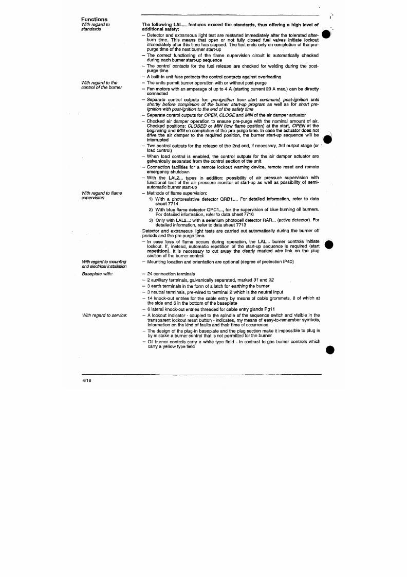
7/18/2019 M14 Thermal Fluid
http://slidepdf.com/reader/full/m14-thermal-fluid 306/486
With
regard to flame
- When load control is enabled, the control outputs for the air damper actuator are
galvanically separated from the control section of the unit
- Connection facilities for a remote lockout warning device, remote reset and remote
emergency shutdown
- With the LAL2... types in addition: possibility of air pressure supervision with
functional test of the air pressure monitor at start-up as well as possibility of semi
automatic burner start-up
- Methods of flame supervision:
Technical data
U^ns voltage AC 220 V -1 5 % ... 240 V + 10 %.
LAL2...
also
A C 100 V -15 % ... 110 V + 10%
50 Hz-
6 %
... 60
Hz +
6
%
3 .5 VA
Mains frequency
Consumption
Unit fuse, built-in
T6 , 3H 250
V
according
to
IEC
127
Unit fuse, external 10 A max.
Radio interference protection
N according to VDE 0875
Permissible input current to tenninal
1
5 A permanently, peaks of up to 20 A max.
Permissible current load of control terminals
4 A permanen tly, peaks
of
up
to
20
A
max.
to ta l 5 A max.
Environmental conditions
- Transport
Climatic conditions
Temperature
Humidity
Mechanical conditions
- Operation
Climatic conditions
Temperature
Humidity
IEC721-3-2
class 2K2
-50...+60 °C
< 95 % r.h.
class 2M2
IEC721-3-3
class 3K5
-20...+60 °C
< 9 5 % r.h.
Weight
- Burner control
- Baseplate
approx. 1000 g
approx. 165 g
Required switching capacity
of
switching devices
- Between terminals
4
an d
5
1
A
- Between terminals 4 an d 12 1 A
- Between terminals 4 and 14
5 A, peaks 20 A
Pennissible mounting position
Degree of protection
optional
IP 4 0
CE conformance
Accordng to the dreclives of the European Community
Electromagnetic compatibility EMC
89/336 EEC include. 92/31 EEC
Gas appliance directive 90/396 EEC
Emissions EN 50081-1
Immunity EN 50082-2
Condensat ion , fo rmat ion of Ice and ingres s of water are not permitted.
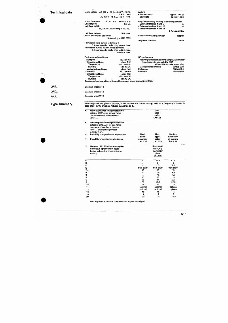
7/18/2019 M14 Thermal Fluid
http://slidepdf.com/reader/full/m14-thermal-fluid 307/486
QRB...
QRC...
RAR...
See data sheet 7714
See data sheet 7716
See data sheet 7713
Type summary
Switching times
are
given
in
seconds,
in the
sequence
of
burner start-up, valid
for a
frequency
of 50
Hz.
in
case of 60 Hz, the times are reduced by approx. 20 %.
Connec t ion
diagrams
LAL1.. .
[1
®D ^
(ZJOC
BV1
g
BV2
S
|fe(|biy=a'
X
LK
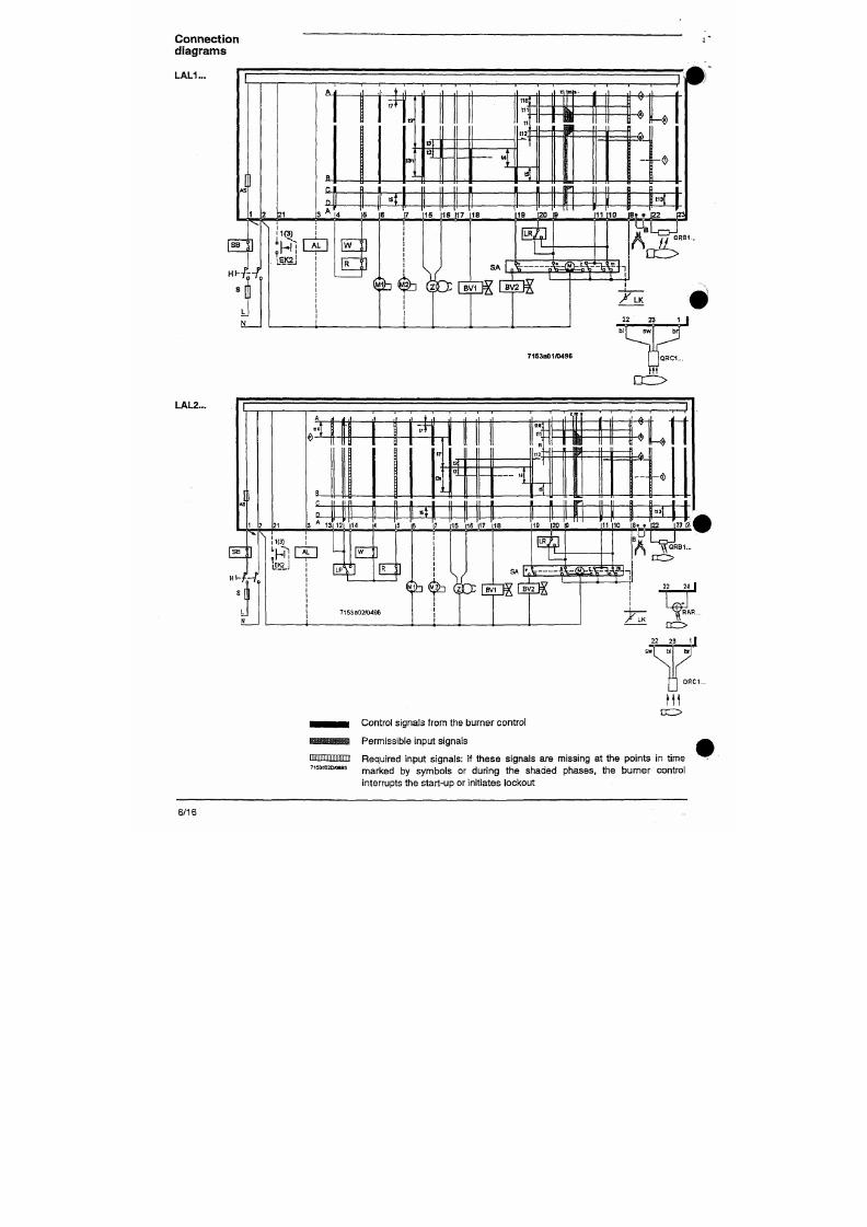
7/18/2019 M14 Thermal Fluid
http://slidepdf.com/reader/full/m14-thermal-fluid 308/486
7153a01/0496
LAL2...
Flame supervision
LAL1... with detector
QRB..
QRC1.
Required min. detector cun^nt at
AC
230 V
l^ax. p erm , detector current without flame
Max. possible detector current
+pole of instrument
Length of detector line
- In the same cable as the control lines
- Separate cable in cable duct
- Three-core cable
- Two-core cable for
the
detector line
(bl, sw ], separate one-core cable
for the phase (br)
95 ^A
160
|iA
to term. 23
3 0 m max.
1000 m max.
BOpA
12nA
to term. 23
1 mmax.
2 0
m
max.
23 LAL1...I I 22 23 1
LAL1...|
QRB1..
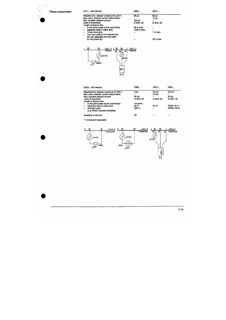
7/18/2019 M14 Thermal Fluid
http://slidepdf.com/reader/full/m14-thermal-fluid 309/486
LAIZ... with detector
QRB..
QRC1...
RAR...
Required m in. detector current at AC 230 V
It ax. pe mi. detector current without flame
Max. possible detector current
+pole of instalment
length of detector line
- In the same cable as the control lines
- Separate cable in cable duct
- Shielded cable
8 ^
35 pA
to
term.
22
not perm.
20 m
200 m
3.9 nA
0.8 tiA
to tenri. 22
2 0 m*
6. 5
MA
25 ^A
to term. 22
RAR7: 30 m
RAR8; 100 m
Connect ion
diagrams
L A U . . .
QRC1...
EKI*
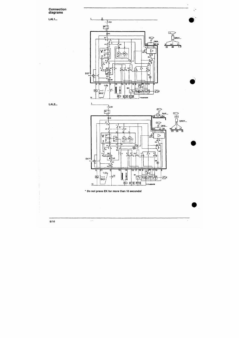
7/18/2019 M14 Thermal Fluid
http://slidepdf.com/reader/full/m14-thermal-fluid 310/486
LAL2...
Legend a
for the entire data sheet
AL
AR
AS
B
BR
BV...
d.;.
Etc..
FR
FS
H
L...
L3
UK
LP
LR
M...
bl
br
Changeover limit
switch
for OPEN position
of the air damper
Remote lockout warning device (alarm)
Main relay (load relay) with contacts ar...
Unit fuse
Wire link
(on
the plug section of
the
burner control)
Lockout relay w ith contacts br...
Fuel valve
Contactor or relay
Lockout reset button
Rame relay with contacts fr...
Rame signal amplifier
Mains isolator
' Fault signal lamp
Operational readiness indication
Air damper
Air pressure monitor
Load controller
Fan or burner motor
Blue core
Brown core
m
NTC
QRB...
QRC1...
R
RAR...
RV
S
SA
SB
SM
V
V
W
Z
z
sw
Auxiliary switch for the M IN position of
the air damper
NTC resistor
Photoresistive detector
, Blue flame detector
Control thermostat or pressurestat
Selenium photocell detector
Continuously adjustable fuel valve
Fuse
Air damper actuator
Safety limiter (temperature, pressure, etc.)
Synchronous motor of the sequence
mechanism
Rame signal amplifier
In the actuator auxiliary changeover
switch for the release of fuel in function
of the air damp er position
Limit thennostat or pressure monitor
Ignition transformer
In
the actuator limit
switch
for the
CLOSED position of the air damper
Black core
For circuit variants refer to "connection examples"
Warnings
• In the geographical areas wh ere DIN standards are in use, the installation m ust
be in compliance with VDE requirements, particularly with the standards
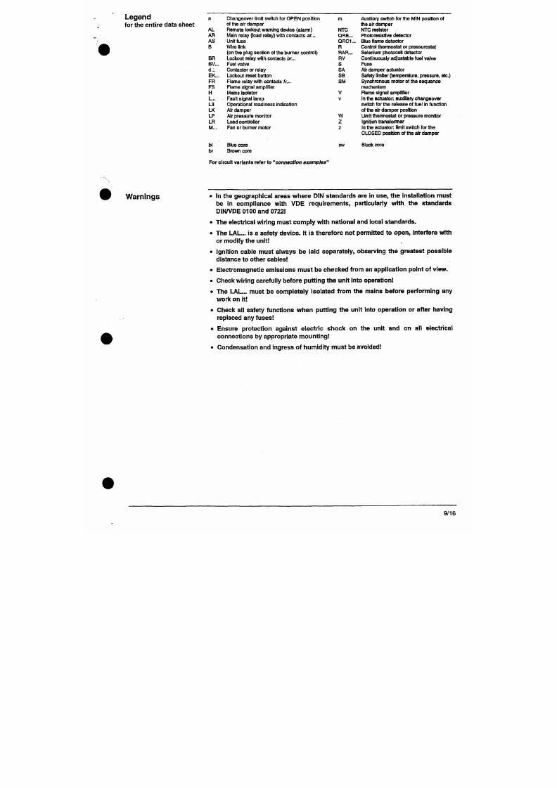
7/18/2019 M14 Thermal Fluid
http://slidepdf.com/reader/full/m14-thermal-fluid 311/486
DIN/VDE 0100 and 0722
• The electrical wiring must comp ly with national and local standa rds.
• The LAL ... is a safety device. It is therefore not permitted to op en, interfere with
or modify the unit
• ignition cable must always be laid separately, observing the greatest po ssible
distance to other cables
Control program
under fault conditions
and lockout indication
In case of any disturbance, the sequence switch stops and with it the lockout indicator.
The symbol above the reading mark of the indicator gives the type of d isturbance:
^
No start,
because one contact has not been closed (see also
"Prerequisites for
^ burner
start-up")
or
lockout during or after, completion of the control sequ ence
due to extraneous light (e.g. non-extinguished flame, leaking fuel valves, defects
in the flame supervision circuit, etc.).
J^
Interruption of start-up sequence,
because the OPEN signal has not been
delivered to terminal 8 by limit switch a. Terminals 6, 7 and 15 remain under
voltage until the fault has been corrected
p
With LAL2...:
lockout,
because there is no air pressure indication at the beginning
of air pressure control. Every air pressure failure after this moment In time
leads to a lockout, too
I Lockout due to a fault in the flame su pervision circuit.
y^
Interruption of start-up sequence,
because the position signal for the low flame
position has not been delivered to terminal 8 by auxiliary switch m . Terminals 6, 7
and 15 rem ain under voltage until the fault has been corrected
1 Lockout, because no flame signal is present after completion of the safety time .
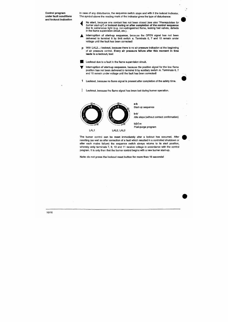
7/18/2019 M14 Thermal Fluid
http://slidepdf.com/reader/full/m14-thermal-fluid 312/486
Lockout,
because the flame signal has been lost during burner operation.
a-b
Start-up sequence
Notes
Engineering
LAL2
7 15 16 17 18
(T) @ 7153s03ffl396 ®
Switches, fuses, earthing, e tc. must be in compliance with the local regulations. For the connection of v alves
and other components, the diagram provided by the burner manufacturer is valid.
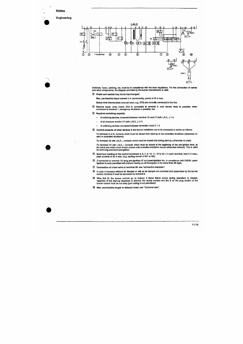
7/18/2019 M14 Thermal Fluid
http://slidepdf.com/reader/full/m14-thermal-fluid 313/486
G) Phase and neutral may not be interchanged
Max. p ermissible input current: 5 A permanently, peaks of 20 A m ax.
Safety limit therm osta ts (manual reset, e.g . STB) are normally connected in the line.
(D Remo te reset: when button EK 2 is connected to terminal 3, only remote reset is possible; when
connected to tenTiinal 1 , em ergency shutdown is possible, too .
(D Required switchin g capacity
C o n n e c t i o n
e x a m p l e s
19
20 91 1 1 0 8 Connection of actuators without changeover
TIT^
N
S A E V
iwg
^ ^ -
TlK
limit switch for the CLOSED position
z
is
adjusted
to the air
volume required
for low
flame operation.
18
19 17 9 20 11 10 8 6
LR
N^^^^_5>^1K
Control of the air damper actuator during
operation by control signals at terminal 17.
Signal path: refer
to
"connection
diagrams".
19 20 9 11 10 8 6
S
^ i i
Control of a fuel valve via terminal 20
(Burner w ithout
air
damper
or
with
an air
damper
not c ontrolled by the burner control).
The
relay
is
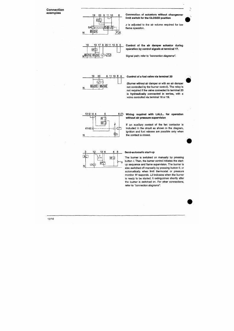
7/18/2019 M14 Thermal Fluid
http://slidepdf.com/reader/full/m14-thermal-fluid 314/486
not required
if
the valve connected
to
terminal
20
is hydraulically connected in series, with
a
valve controlled via terminal
18 or 19.
C o n n e c t i o n
e x a m p l e s
Two-stage expanding
flame burner
C
Mi^m
1 5(13"/t3n)
16(13) 1 7 1 8
U'¥>
19 9 20 11 10 8
SA 11
L R
^
[^lE [A
IV
3 1 1 — r x
^VJ
^ ^ f ^ - H i
7153a05/1195
; *TK
Load control with an on/off controller. The air dannper is closed during burner off
periods.
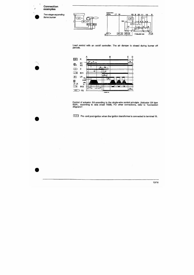
7/18/2019 M14 Thermal Fluid
http://slidepdf.com/reader/full/m14-thermal-fluid 315/486
Modulating expanding
flame burner
16 17 18 19 20
1110
U
LR
SA
-M—^M
BV1
i
LR
N'
-z-
( f> jy HE Rv LK
SA
, a . ^ z .
7153a06/119S
Load control with a m odulating controller w ith galvanically separated control contacts for
OPEN and CLOSED positions.
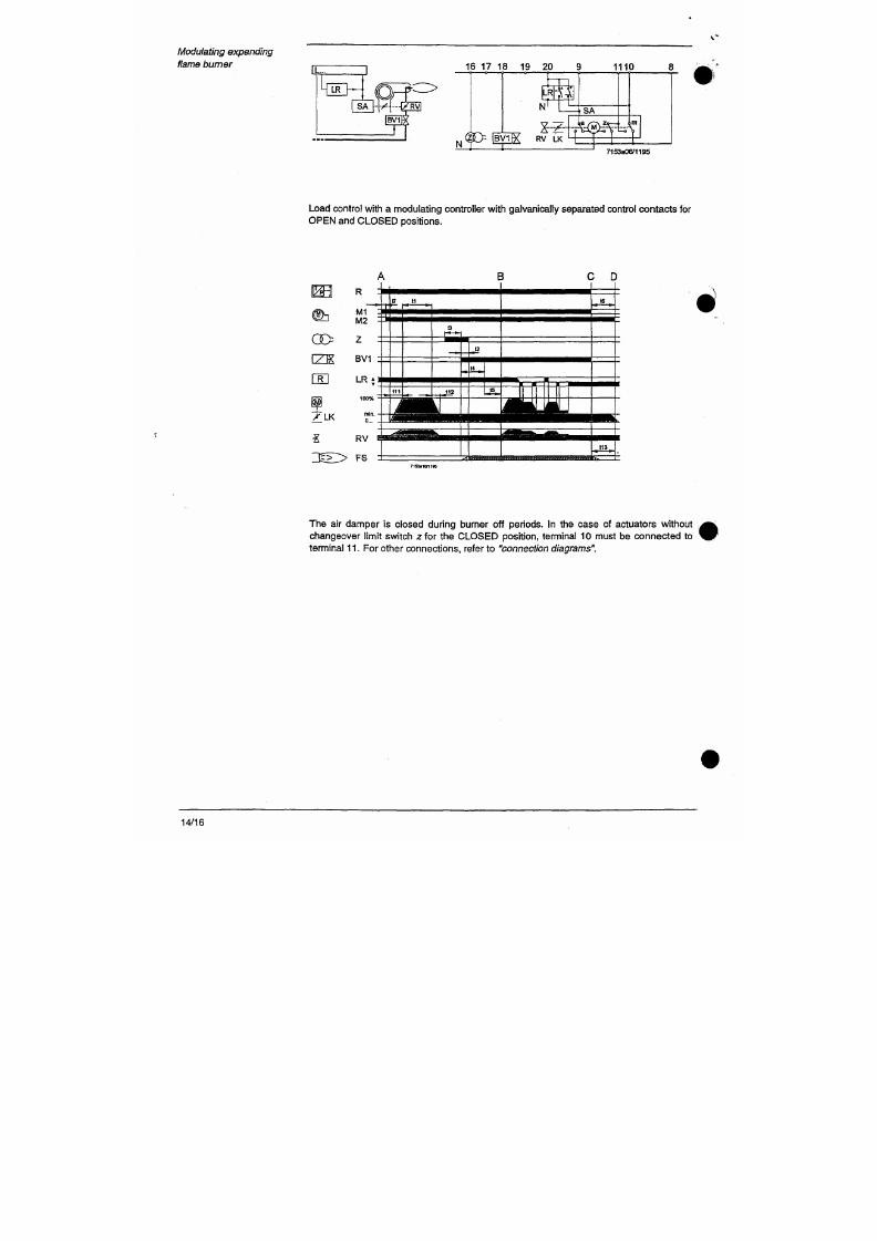
7/18/2019 M14 Thermal Fluid
http://slidepdf.com/reader/full/m14-thermal-fluid 316/486
GO
CEl
X L K
Sequence d iagram
Control output
®
®
®
A ... B C æ
1 J
"»IT
II S
" b
III b
IV
V
I
VI
VII
I
VIII
I
IX
X
I
XI =
XII I *
XIII
I
XIV ^
116
LLLLU
l l l l l l
tio*
n - r m
i r
u
I J J I M
M i l l
M I M I
J?.
" • -
. I 2 _
1311
. "
•
l u l l
• T i l l
I I I M
BO
M i l l
I I I M
inn
I H
. •"
D at termin
f7\(Pfi'
(A) (35
Of
— ®
®
iSSk
(S9
1
— ©
— @
®
®
Positions of
the
lockout indicator
I \ \ 1
7 1 5 3 d 0 1 E / 0 1 9 7
H h
^ I I ^ i i i i i iMii i i i ii i i i P i i i ii i i i i • i i i i i i i i i i i i i i i i ^ i i i i i i imii i i i i i i i i i
^ 1 i i i i i i i i i i ii i i i i i i i i i i ii i i i i i i i i i i
["-(iiiiMiiiiiiiiiiiiiiiiiniiii
^
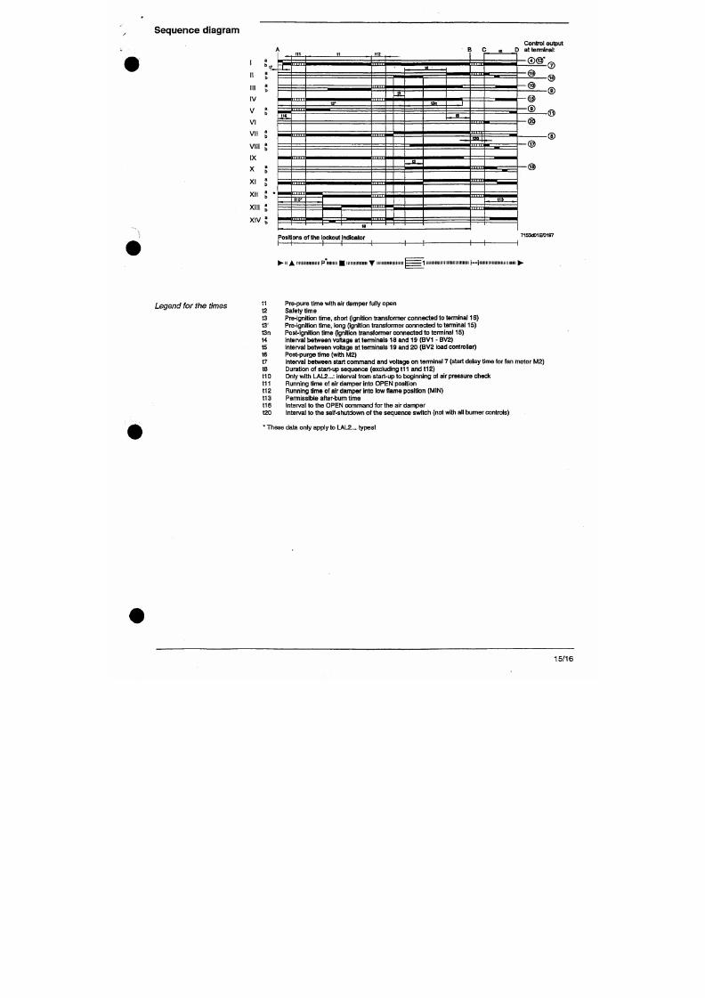
7/18/2019 M14 Thermal Fluid
http://slidepdf.com/reader/full/m14-thermal-fluid 317/486
Legend for the times
t1 Pre-pure time with air damper fully open
t2 Safety time
t3 Pre-ignition time, short (ignition transfomier connected to terminal 16)
t3'
Pre-ignition time, long (ignition transformer connected to terminal 15 )
t3n Post-ignition time (ignition transformer connected to terminal 15)
t4 Interval between voltage at terminals 18 and 19 (BV1 - BV2)
Dimensions
Dimensions in mm
LAL...
with baseplate AGM 41049055 0
123
^
27,5 27,5
/^ i X
7153m 02/0396
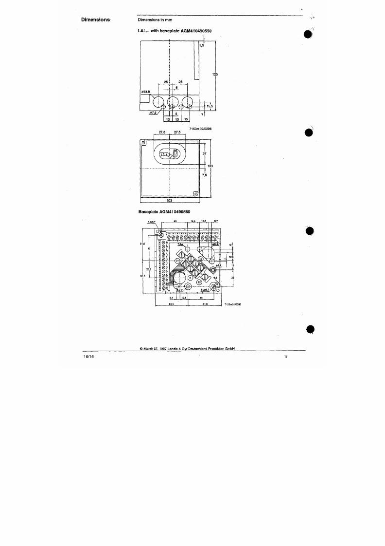
7/18/2019 M14 Thermal Fluid
http://slidepdf.com/reader/full/m14-thermal-fluid 318/486
wm)
;
^
3
7,
1
103
5
AALBORG
I N D U S T R I E S
Jj,
^'
i-.-
Aalborg Industries BV
3200 AC Spijkenisse
Ohmweg 8
3208 KE Spijkenisse
Tlie Netherlands
Tel. +31 (0)181 650 500
Fax +31 (0)181 650 501
Traderegis ter Rot terdam
No . 24234179
VAT No. NL0081.91.694.B.01
E-mail : r tmw ®aalborg- indu st r ies .nl
ht tp: / /www.aalborg- indust r ies .nl
Bankers: Fort is Bank, Rotterdam
Account No. 25.75.69.618
IBAN No. NL85FT5B0257569618
BiC Cod e FTSBNL2R
E.S1SO
9001:2000
m
Cer t i f ied
Company
Mgi lß l tT MOBRiV:
'S^-
^,^iéeli.;-
L IQ W IK lp f i t ; AiAR M Til ilØ PUJHI» eONTR OL
4^*^^/
7/18/2019 M14 Thermal Fluid
http://slidepdf.com/reader/full/m14-thermal-fluid 319/486
f""
T H E C O M P L E T E M O B R E Y H O R IZ O N T A L F L O A T S W IT C H R A N G E
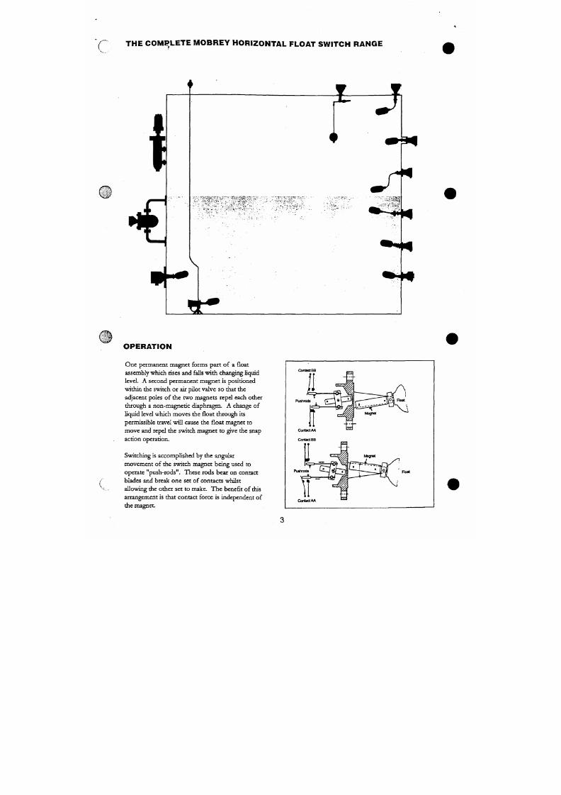
7/18/2019 M14 Thermal Fluid
http://slidepdf.com/reader/full/m14-thermal-fluid 320/486
S W I T C H S E L E C T I O N
AL ARM SWIT CHING • EL ECT RICAL OR PNEUM AT IC
H or iz on ta l o r ve r t i c a l :
High or low alarm switches are of
robu st construction, making them ideal
for a wide range of liquids in industrial
applications.
Dirty
l i qu id a pp l i c a t ion s :
The shrouded model should be
specified, thus eliminating fouling of
the float movement due to deposits or
large particles becom ing wed ged.
S u b m e r s i o n :
Fo r those applictions where the
equipment may b e subject to occasional
or continuous submersion the
submersible mode l should be specified.
H o s e p r o o f
m ar ine
a p p l i c a t i o n s :
Switches have be en specifically designe d
for the reqtiirements of these m arkets
& approval au thorides, (for details o f
approvals contact th e &ctory).
Vacuum applications:
All metallic floats are capable of
operating in full vacuum conditions.
High Alarm
Low Aiarm
High or Low
Aiarm
Viscous liquids
Cranked arm float units should be
specified to enable the o perating
mechanism to be ke pt clear of th e
liquid. Rod extensions shaped to
individual requirem ents are available
to fit all Mobrey level switches.
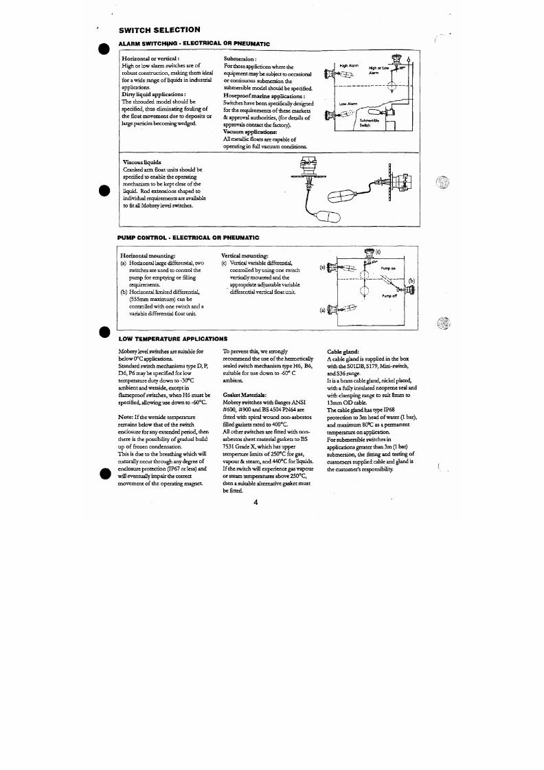
7/18/2019 M14 Thermal Fluid
http://slidepdf.com/reader/full/m14-thermal-fluid 321/486
P U M P C O N T R O L • E L E C T R IC A L O R P N E U M A T I C
H o r i z o n t a l m o u n t i n g :
V e r t i c a l moun t ing :
| ( c )
C H O I C E OF S W I T C H M E C H A N I S M S
ELECTRICAL
T Y P E D
Fo r alternative ma ke and break circuits.
Fu nct ion : 2 independent s ingle pole
single throw con tact sets: "Snap Action" .
May be wired
S.P.CO.
on site.
T Y P E D 6
Fo r switching two independ ent circuits.
Fu nct i on: Do uble pole change over (2
independent circuits): "Snap Action".
T y P E P & P 6
As type D & D 6 b ut with gold plated
contacts for sw itching low power (e.g.
intrinsically safe) elec trical circuits.
T y P E H 6
For use in corrosive area an d/ or lo w
temperature applications. As type D 6
but with gold plated contacts and all
W A R N I N G
Th e plating of gold contact switches
may be perm anendy damaged if this
mechanism
is
used to switch circuits
above the following limits:
300V: 12mA Resistive
24V: 2m H/2 00m A Induct ive
24V: 250m A Resistive
24V : 750mH /10mA Induc t ive
L V D - L o w V o l tag e Direc t iv e .
Thes e switches complywith
the^|;|Ä;.^?',
provisions o f the machinery directive
8 9 / 3 9 2 / E E C a n d t h e L o w V o l t ^ é V . '
Direct ive 73 /23 /E EC . ' -^ -^ r '
Standardsappl ied: EN60947Parts 1
and 5.1
T Y P E B 6
For use in Zone 11 Hazardous A reas.
As type H6 but BASEE FA approved
c oded EX N IIT 6 to BS
4683:
Part 3:
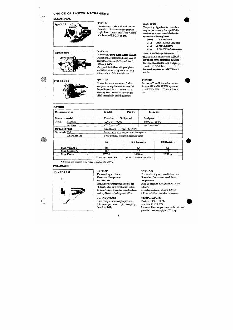
7/18/2019 M14 Thermal Fluid
http://slidepdf.com/reader/full/m14-thermal-fluid 322/486
RATING
mov ing parts hou sed in an inert gas
filled hermetically sealed enclsoure.
1972.
M e c h a n i s m T y p e
D & D 6
P & P 6
H 6 & B 6
GENERAL PURPOSE APPLICATIONS
A L U M I N I U M B R O N Z E W E T S I D E M O D E L S
S0 1 D B/F8 4
4
Contact switc h
Eifrl
-^3
s U J Z i ™
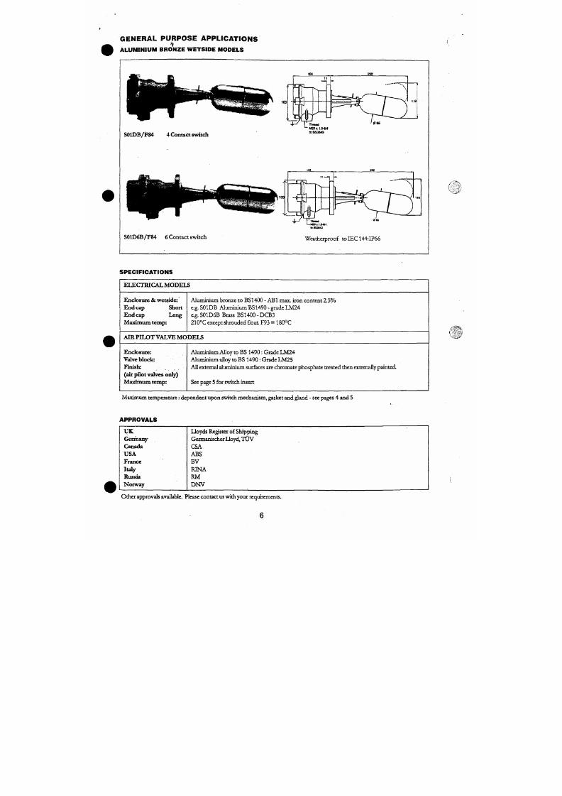
7/18/2019 M14 Thermal Fluid
http://slidepdf.com/reader/full/m14-thermal-fluid 323/486
ttru
S01D 6B /F84 6 C on ta c t sw i t c h
f l l W M d
1—MZO
X t.5
10BS3M3
Weatherproof toIEC144:IP66
O R D E R IN G IN FO R MA TIO N
V ^
Code
S
General purpose a luminium bronze wetside m odels
Switch
Code
01
Fla ng e (H e a d)
Size Rating Standard
M obrey A 18 bar Mobrey
Code
D B
P B
D 6 B
F6 B
A PA
A M A
Switch mechan ism
4 Contac t-generali» short end cap
4 Contact
-
gold plated contacts
1>
short end cap
6 Co ntact - general
1>
long end cap
6 Conta ct - gold plated contacts t long end cap
Pneumatic on/ off
Pneumatic modtüating
C O D E
F84
F185
F 6 8 / +
F264
F 2 1 / +
F 1 0 4 / +
F9 3
Float - appl icat ion information
High or low alarm or 2 off
for pump control wide differential
Horizonta l pum p control
Hor izontal limited differential
Verticat pum p control or alarm
Crank ed arm vertical or horizon tal ( See pag e 19 for arm lengths )
Shro uded for dirty liquids Silicone rubb er gaiter with 316 stainless steel
shroud and float
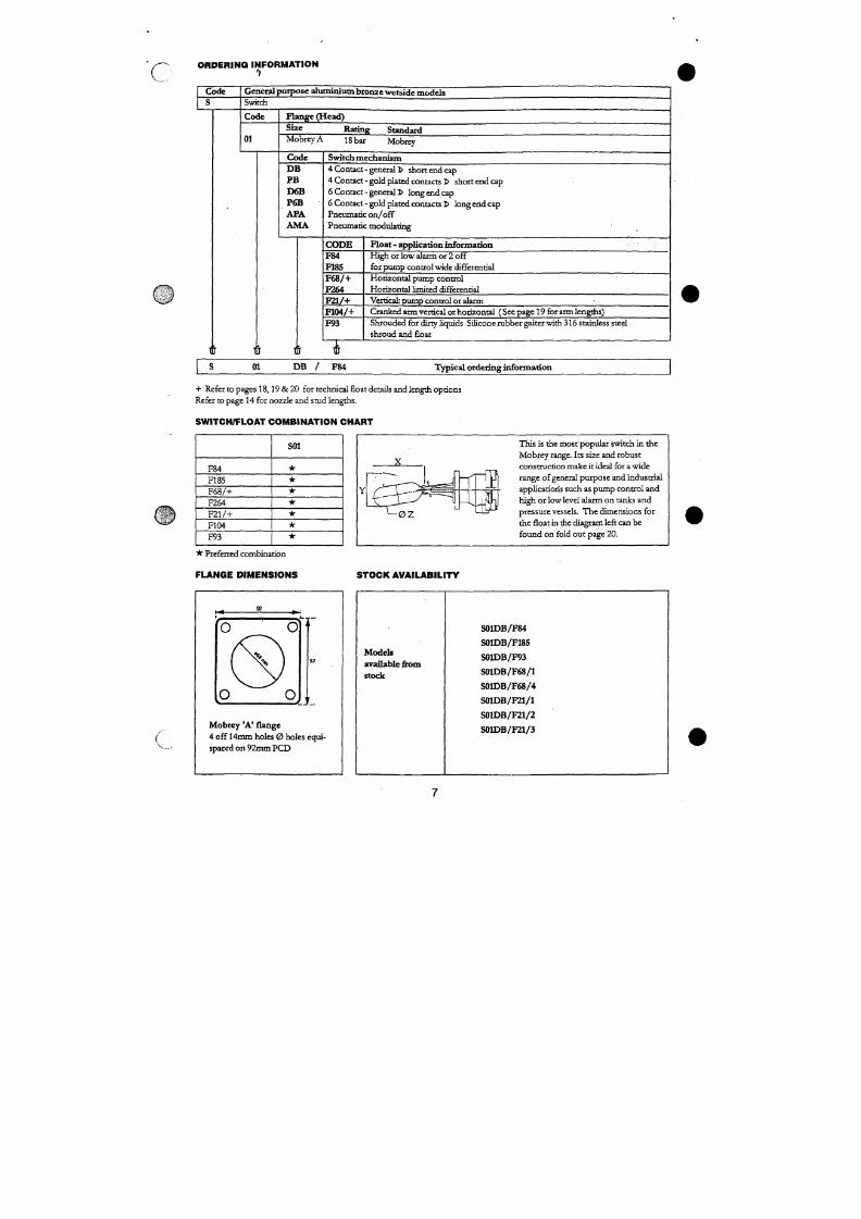
7/18/2019 M14 Thermal Fluid
http://slidepdf.com/reader/full/m14-thermal-fluid 324/486
t 1 1
J
i
5
01
D B
/
F84
Typical order ing information
+ Refer to pages 18,19 & 20 for technical float details and length opti ons
Refer to page 14 for nozzle and smd lengths.
M A R I N E A P P L I C A T I O N S
S U B M E R S I B L E
•
H O S E P R O O F
•
M A R I N E
Aluminium bronze submersible /hoseproof
Stainless stee l sub mersible /hoseproof
103
i S03*B
,: S179*B
1 S195*B
1 ^
101
^
IT
Sld3*
S181*
ConduKanry
PQisteDttMtwao
S P E C I F I C A T I O N S
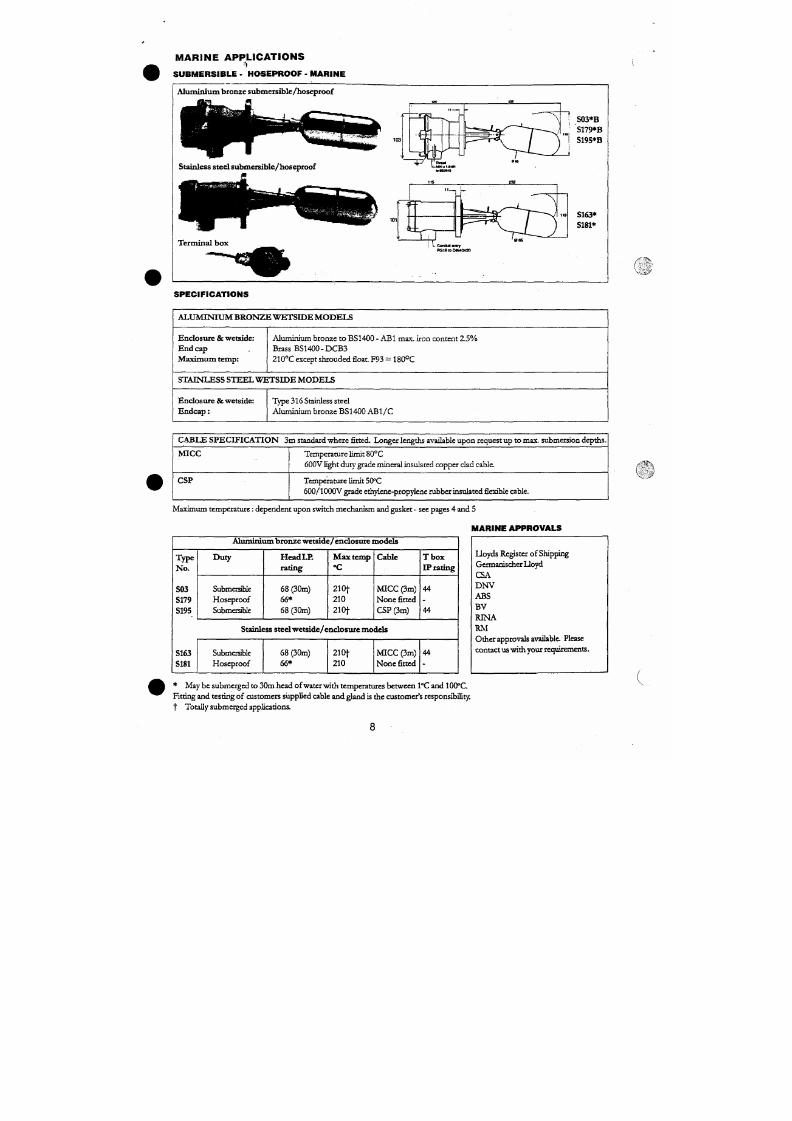
7/18/2019 M14 Thermal Fluid
http://slidepdf.com/reader/full/m14-thermal-fluid 325/486
A L U M I N r U M B R O N 2 æ W E T S I D E M O D E L S
Enclosure & wetside:
End cap
Ma x imum te mp:
Aluminium bronze to BS1400 - ABl max. iron content 2 .5%
Brass BS1400-DCB3
210°C except shroud ed Boat. F93 = 180°C
S T A I N L E S S S T E E L W E T S I D E M O D E L S
ORDE RING INF ORM AT ION
Code
S
General purpose, submerisb le . hoseproo f & ma rine appl icat ions
S^witch
Cod e
03
179
195
163
181
Plange (bead) S ize
MobreyA
MobrejrA
MobrevA
M o b rey A
MobreyA
Code
D
P
D 6
P6
Rating
18 bar
18
bar
18
bar
18
bar
18
bar
Switch mechanism
Standard
Mobrey
Mobrey
Mobrey
Mobrey
Mobrey
4 contact
-
general
4 contact - gold plated conta cts
*6 conta ct - general
*6 contact - gold plated contac ts
* No te: n ot for use with stainless steel wetside/en closure models SI 63 & S181
Code
B
Enclosure bousing
Aluminium bron ze: no cod e letter with 5163 or 5181 stainless steel models
Cod e
F84
F185
F98
F 6 8 / +
F 2 1 / +
F 264
Float - appl icat ion information
General purpo se high or low alarm
or 2 off for pu m p control
Hor izon tal pum p cont ro l
Vertical pum p control o r alarm
Hor izonta l limited differential
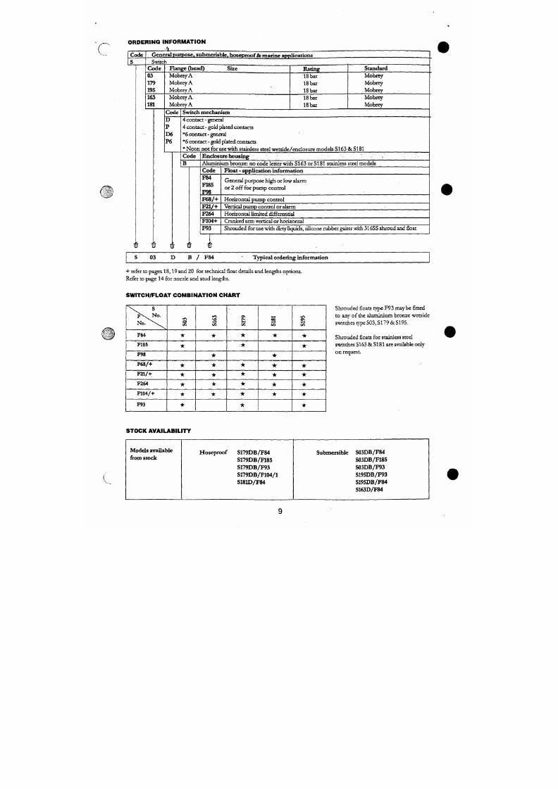
7/18/2019 M14 Thermal Fluid
http://slidepdf.com/reader/full/m14-thermal-fluid 326/486
1
J 1
J
t
r
t
7
F104+
F 9 3
Cranked arm vertical or horizo ntal
Shro uded for use with dirty Hquids, silicone rubb er gaiter with 316SS shroud and float
03
B / F8 4 Typical ordering information
G E N E R A L P U R P O S E A P P L I C A T I O N S
ST AINL ESS ST E^L WET SIDE M ODEL S
S 3 6 D A / F 8 4
TTvead
M20x1.5-6n
toBS3643
Weatherproof to E C 144:IP66
» 126
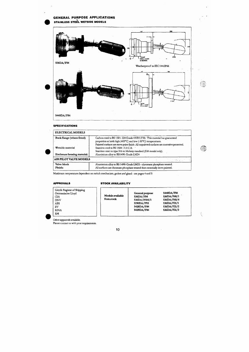
7/18/2019 M14 Thermal Fluid
http://slidepdf.com/reader/full/m14-thermal-fluid 327/486
T 7 ^
TKHEAO
TO B.S.3M3
S 440DA/F 84
c
3 . 1 . 1 .
ORDERING
_ . i —
C OD E
S
II FOR
Mi
UTIO
H
Genual purpose stainless steel wetside models
Switch
C O D E
3«
190
440
441
424
425
489
490
428429
430
431
432
417
418
419
433
434
488
435
436
43 7 V
i-lange
(Head)
Size
Mobrey
A
Mobrey A
3"
4"
3"
4"
3"
3"
DN65DN80
DNIOO
DN12S
D N I 5 0
D N 6 5
D N 8 0
DNIOO
DN125
DN ISO •
D N 8 0
DNIOO
DN125
DN150
C OD E
D
P
Rating
33.8
bar
33.8
bar
150 RF
I50RF
300
R F
300 RF
600
RF
900 R F
PN 16
PN 40
PN 64
Switch Mechanism
4 Contact
-
General
4 Contact - Gold Plated Contacts
Standard
Mobrey
Mobrey : Use float F93 only
To BS 1560
o r
ANSI
B16.S
to BS 4504
or
DIN 2633
To BS 4504
or DIN 2635
To BS 4504
or DIN 2636
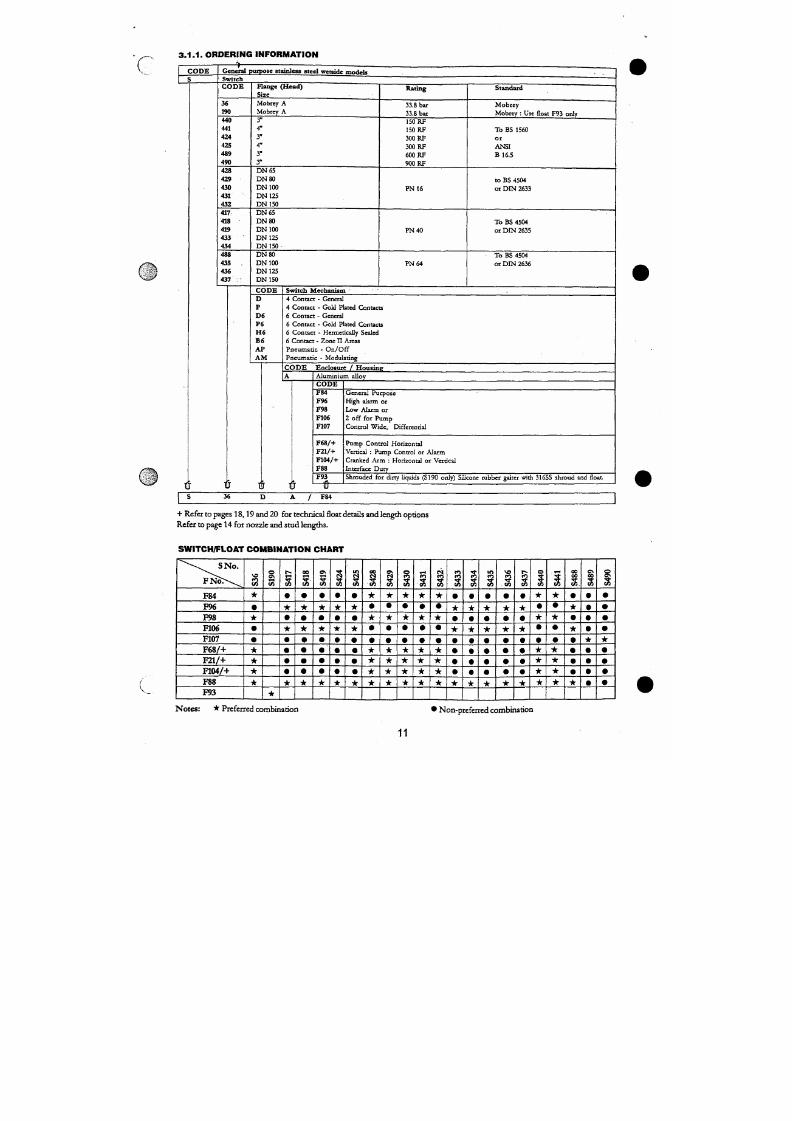
7/18/2019 M14 Thermal Fluid
http://slidepdf.com/reader/full/m14-thermal-fluid 328/486
D 6
P6
H 6
B6
AP
AM
6 Contact - General
6 Contact - Gold Plated Contacts
6 Contact - Hermetically Sealed
6 Contact - Zone II Areas
Pneumatic
-
On/Off
Pneumatic - Modulating
CODE Enclosure
/
Hous ins
A Aluminium allov
H A Z A R D O U S A R E A A PPL IC A T IO N S
FLA ME P R O O F ZO N E 1 G A S G R O U P I & | IC MO D E LS
133
IJhM
S2S0D A /F84
Weatherproof to IE C 144: IP66
C ondu i t e n t ry th re a d
Gunmeta l body 25tnm
Aluminium body 20nim
/ 3 6 5
For min in g a pp l i c at ions
S276 & S277 are supplied with flanged
adaptor suitable for a bander type cable
gland, the use o f which is obligatory
S P E C I F I C A T I O N S
( '-
B a c k f l a nge
(where fit ted)
W e t s i d e m a t e d a l
Carbon steel to BS 15 01 :22 4: Gra de 430B LT50. T his material has guaranteed properties
at both high (400° Q and low (-50°Q temperatures. Painted surfaces are stove paint finish whilst
all unpainted surfaces are corrosio n p rotected .
Stainless steel to BS 15 04 :31 6 C I 6
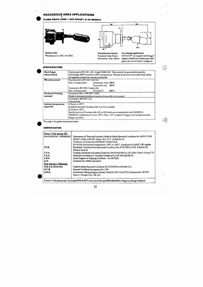
7/18/2019 M14 Thermal Fluid
http://slidepdf.com/reader/full/m14-thermal-fluid 329/486
E n c l o s u r e / h o u s i n g
m a t e r i a l
Max. working temp* : Alum inium body 400°C
Gun metal body 350OC
Gunm etal to BS 1400: Grade L G2 .
Max. working temp*: S275 &S 277 200°C
Aluminium alloy to BSl 490: LM 25
Finish is Chromate phosphate treated and externally stove painted
r
O R D E R I N G
1 C O D E S
I N F O
RM
lATIO
N
Swi tc l f fo r haz ard ous area app l i c a t io ns , f lameproof zon e 1 gas e«> "P I »" d l i e m ode l s
C O D E
250
275
2 7 6 < >
2 7 7 < >
256
257
278
251
254
260
261
253
2 5 5 ^
26»
2 7 2 '
268
270
271
F l a n g e ( H e a d ) S i z e
C O D E
D
P
D 6
P 6
H 6
M o b r e y G
Mobrej r G
M o b r e y G
M o b r e v G
3"
4"
6"
3"
4"
3"
3"
O N 8 0
D N I O O
D N 1 2 5
D N 8 0
D N I O O
D N 1 2 5
D N I S O
Rat in f r
21 bar
21 bar
21 bar
21 bar
150 RF
150 RF
150 RF
300 RF
300 RF
600 RF
900 RF
P N 4 0
P N 6 4
W e t s i d e
Stainless s teel
G u n m e t a l
Stainle ss s teel } ^o ne 1 gas group I models
G u n m e t a l
To BS 1560
o r
ANSI
B 1 6 . 5
ro BS 4504
o r D I N 2 6 3 5
To BS 4504
o r D I N 2 6 3 6
S w i t c h M e c h a n i s m
4 Contact - General
4 Contact - Gold Plated Contacts
6 Con tac t - Genera l
6 Con tac t - Go ld Pla t ed Conuct s
6 Con tac t - Heimedcal ly Sealed
C O D E
A
G
X
N o t e : T h e B A S E E F A / C E N E L E C
cert i ficat ion covering use -20°C to -60°C
ambien t t empera tu re requ i res the
hermedcal ly sea l ed swi t ch mechan i sm type
H6 to be fitted.
E n c l o s u r e / H o u s i o e - J
A l u m i n i u m A l l o y
Gunmeta l (mandato ry on gas g roup 1 swi t ches : <>)
Suffix X must be specified for appl icat ions with ambient temperatures -20°C to -60°C
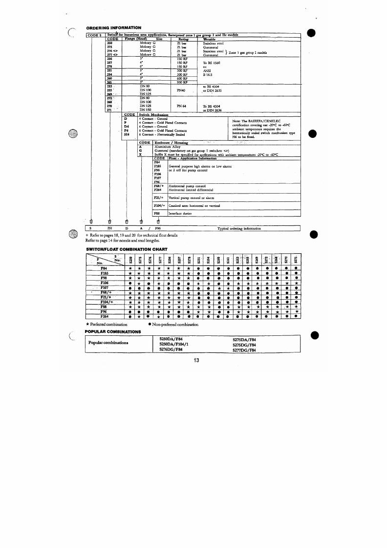
7/18/2019 M14 Thermal Fluid
http://slidepdf.com/reader/full/m14-thermal-fluid 330/486
C O D E
F 8 4
F185
F 9 8
F106
F107
F 9 6
F 6 8 / +
F l o a t - A p p l i c a t i o n I n f o r m a t i o n
Genera l pu rpose h igh a l arms o r l ow a l arms
or 2 o f f fo r pump con t ro l
H o r i z o n t a l p u m p c o n t r o l
CHEMICAL APPLICATIONS
P.T.F.E. WETSIDE
S3S7D/F317.
S357P/F317
1 J
^ ^ g J L f
71
- 1
124
18 —
Mr
é- ^
i
_
1 Conduit entry
^ P g 1 6 t o D I N 4 0 4 3 0
ST'
297
1063
\
\
1
)
I
112
S P E C I F I C A T I O N S
T y p e n u m b e r
Sw i tc h me c ha n i sm
H o u s i t i g n i a t e d a l -
W e t s ide ma te z i a l
Fin ish : .
I P r a t i n g
S357D/F317
General
Aluminium alloy
P T F E
Chromate phos/pa inted
IP66
S357P/F317
Gold plated
Aluminium alloy
P T F E
Chromate phos/pa inted
IP66
N ote s :
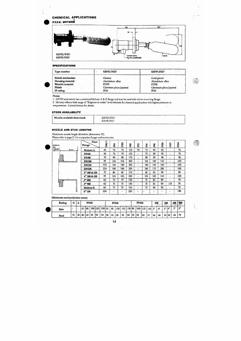
7/18/2019 M14 Thermal Fluid
http://slidepdf.com/reader/full/m14-thermal-fluid 331/486
1. S357D level switch has a comb inedM obrey A & E flange and may be used with either m ounting flange.
2.
M obr ey offers a wide range of "Engineer to or der " level switches for chemical applications with higher pressures or
temperatures. Consult factory for details.
S TO C K A V A ILA B IL ITY
F L OAT CHAMBE RS
Fabricated chambers
UITHORAUAL
175
Switch
Switch
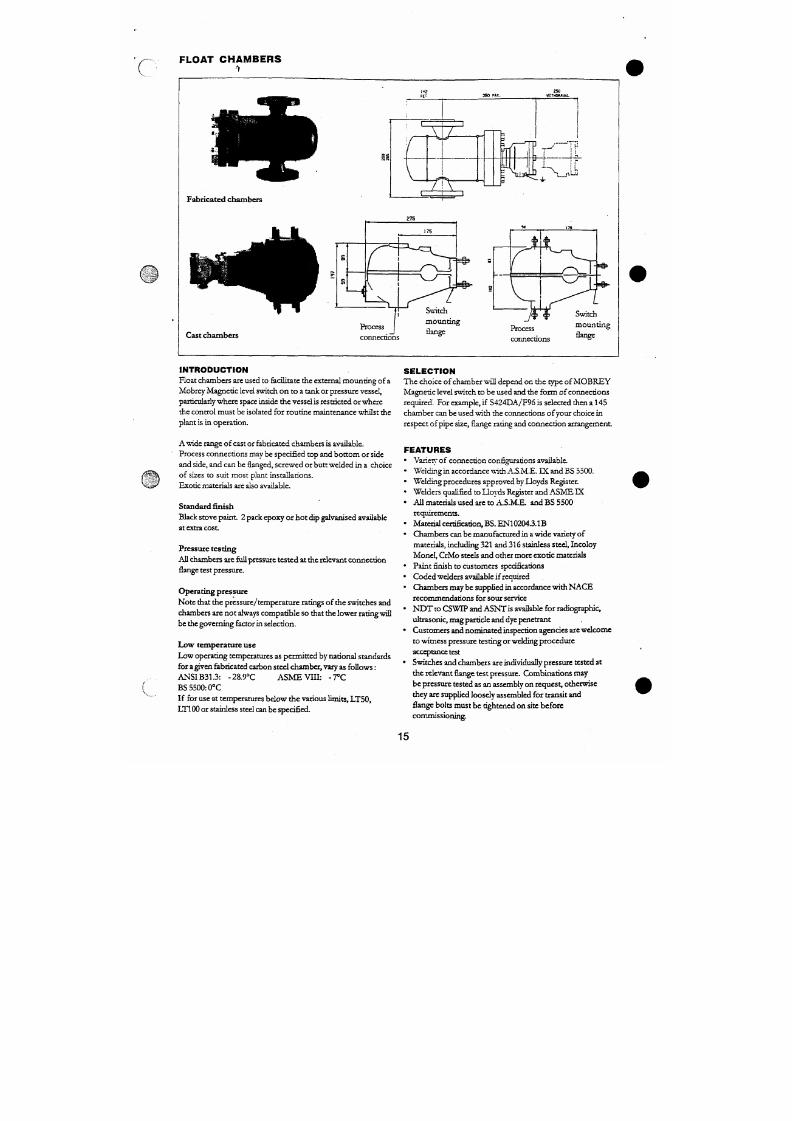
7/18/2019 M14 Thermal Fluid
http://slidepdf.com/reader/full/m14-thermal-fluid 332/486
C a s t c ha mbe rs
Process
connections
moun t ing
flange
Process
connections
moun t ing
flange
I N T R O D U C T I O N
Float chambers are used to feidlitate the external mounting of a
S E L E C T I O N
Th e choice of chamber will depend on the type of M OB RE Y
F A B R IC A T E D C H A M B E R D I M E N S I O N S
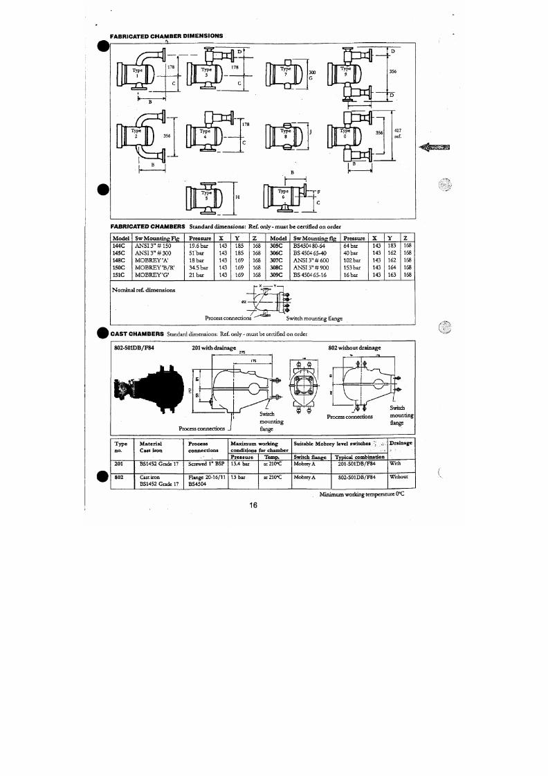
7/18/2019 M14 Thermal Fluid
http://slidepdf.com/reader/full/m14-thermal-fluid 333/486
F A B R IC A T E D C H A M B E R S S tan da r d d im ens i ons : Re f. on lv - m u s t be ce r ti f ied on o rde r
M o d e l
144C
145C
148C
S w M o u n t i n g F i g
A N S I 3 " # 1 5 0
A N S I 3 " # 3 0 0
M O B R E Y ' A '
P r e s s u r e
19.6 bar
S l b a r
18 bar
X
143
143
143
Y
185
185
169
Z
168
168
168
M o d e l
305C
306C
307C
S w Mount ing f ig
BS4504 80-64
BS 4504 65-40
A N S I 3 " # 6 0 0
Pressure
64 bar
40
bar
102 bar
X
143
143
143
Y
183
162
162
Z
168
168
168
r
v.
FA BR IC A TED C H A M BER S : O R D ER IN G IN FO R MA TIO N
Code
144C
14SC
148C
150C
IS lC
305C
306C
307C
308C
309C
O
MatéSial switch flange max . Pressu re aO'C Max Tem p °C See page 4 for gasket l imits
Carbon steel/A NS I 3" Class 150 19.6 bar 400°C
Carbon steel/ANSI 3 " Class 300 51 bar 400''C
Carbon steel/Mo brey'A' 18 bar 400°C
Carbon steel/Mobrey TB/R' 34.5 bar 400°C
Carbon steel/M obrey 'G' 21 bar 400°C
Carbon steel/BS 4504 DN8 0 PN64 64 bar 400°C
Carbon steel/BS 4504 DN6 5 PN40 40 bar 400''C
Carbon steel/ANSI 3" Class 600 102 bar 400''C
Carbon steel/ANSI 3" Qass 900 153 bar 400°C
Carbon steel/BS 4504 DN6 5 PN I 6 16 bar 400''C
C O D E
1
2
3
4
5
6
7
8
9
0
Process Coimecdon Style
Side & top or side & bottom Flanged
Side & side Flanged
Side & top or side & bottom Flanged 'with %" flanged vent/d rain
Side & top or side & bottom Flanged with %" threaded vent/dr ain
Top & bottom Flanged
Side & top or side & bottom Flanged (dose centres)
Top & bottom stub pipe
Top & b ottom threadolet or sockolet
Side & side Flanged with '/«" flanged ven t/dr ain
Side & side Flanged with %" threaded vent/d rain
C O D E
00
01
02
03
Process Connect ion size / ra t ins
1"NB Sockolet
1" NPT threaded (female)
1 'A" NPT direaded (female)
2"
NPT threaded (female)
C H A M B E R O P T I O N S T O
C U S T O M E R O R D E R
• Chambers can be manufactured in
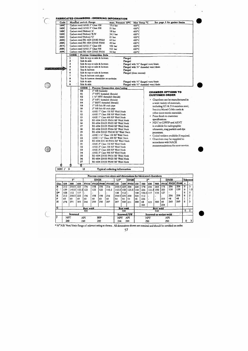
7/18/2019 M14 Thermal Fluid
http://slidepdf.com/reader/full/m14-thermal-fluid 334/486
04
08
10
11
12
13
1"
BSPT threaded (female)
l " N B S c h 8 0 s m h p i p e
2"
NB Sch 80 stub pipe
ANSI 1" Qass 150 RF Weld Neck
ANSI 1" Class 300 RF Weld Neck
ANSI 1" Qass 600 RF Weld Neck
a wide variety of m aterials,
including
321
& 3 16 stainless steel,
Incoloy Monel CrM o steels &
other more exotic materials.
• Paint finish to custome r
spedficarions.
F L O A T S P E C I F I C A T I O N
H O R I Z O N T A L F « 8 P U M P C O N T R O L A N D A L A R M F L O AT
S 3 6 D A / F 6 8 / 4 w i th r od c u t t o / 3 d i m e n si o n
1
>
•
/
r
L
- IW EW
10 B.S.3M3
Switches fitted wi th F 68 tj pe float unit may be adjusted o n site to meet pu m p co ntrol differential re quirem ents.
Th e float is available as a F6 8/1 or F 6 8 / 4 .
Th e F6 8/ 4 has pre-diilled holes along the rod to allow the user to achieve the / 2 and / 3 differentials in the table below:
Maximum intrusion
• \ ^ t s i d e ( m n n ) x ":•••:/:',•"••.'-'^"; ;;> " •.'' '"• *
Min imum SG
Minimum ta nk d im e ns io n
a bo v e /be lo w c e ntr e l ine (mm )
Maxim um differentia l (mm )
F6 8 /1
360
0.72
216
247
F 6 8 / 2
470
0.8
292
360
F 6 8 / 3
590
0.82
368
483
F 6 8 / 4
643
0.85
406
555
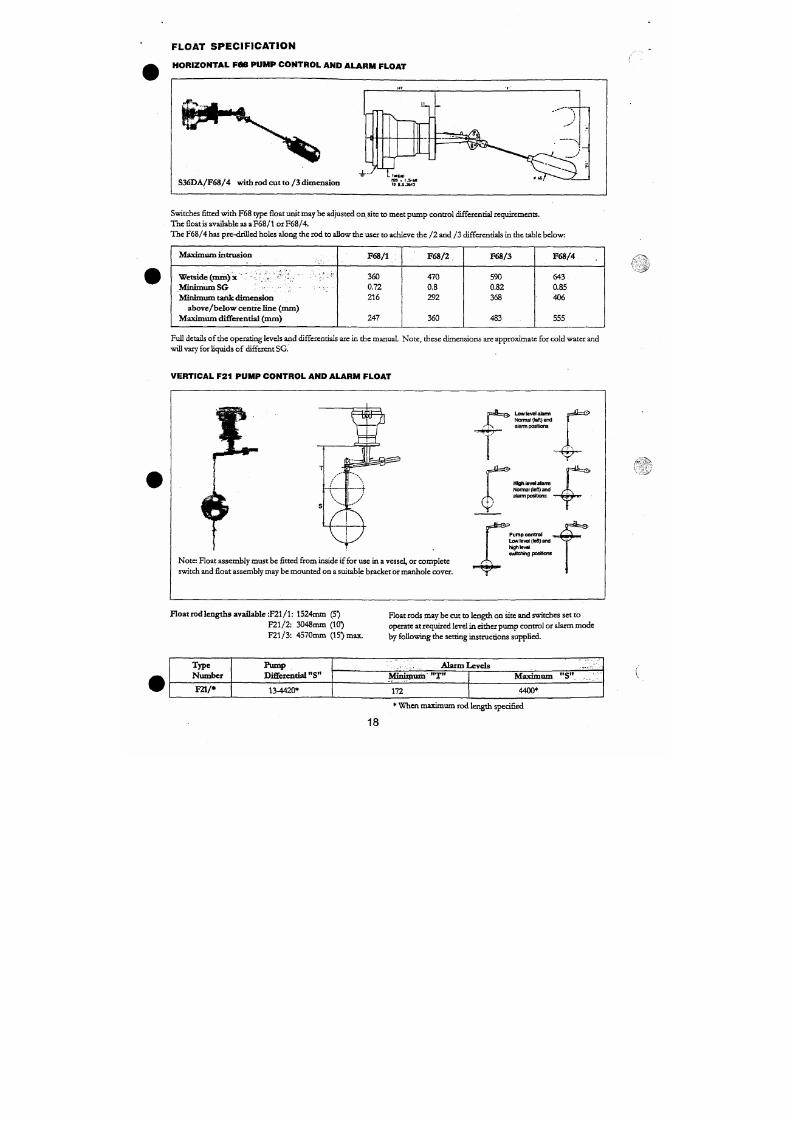
7/18/2019 M14 Thermal Fluid
http://slidepdf.com/reader/full/m14-thermal-fluid 335/486
Full details of the o perating levels and differentials are in the manual. No te, thes e dimensio ns are approxim ate for cold water and
will vary for liquids of different SG.
V E R TIC A L F21 P U MP C O N TR O L A N D A LA R M FLO A T
C R A N K E D A R I^ FLO A TS F l 04
H O W T O O R D E R :
Specify - F104 float with:
1. A and B or V and W dims. 4. Mobrey magnetic switch head
2 Liquid in contact type
no .
(eg. SOID B/F)
3.
Specific gravity of liquid 5. State land or mar ine application
A + B , Must not
f e x c e e d
V + W 7 5 0 i n m
A or V ' Shou ld not
be less
B or W than 75 mm
For Straight arm float, suffix float number with "B' dimension as required
H O R I Z O N T A L L Y M O U N T E D S W I T C H E S
F o r l a n d a p p l i c a t io n
A and B dimensions with relevant minimum specific gravity
O
A ^ 75 100 125 190 17 5 2 00 2 2 5 2 5 02 75 3 0) 3 2 5 3 5 03 75 40 04 2 5 450|475 500|S25|5SO|575| eOo|625|6So| 675l'B'rriril
ISO
200
250
.64
J64
er
.70
SB
.73
.70
Æ7
^
.73
.76
.72
IS
.78
.71
.73
yr
.78
X
71
.75
* l
.72
79
.80
Si
.73
.77
X
sa
.73
.82
.74
.80
.84
.85
.75
.78
.76
.86
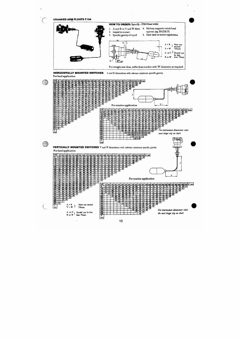
7/18/2019 M14 Thermal Fluid
http://slidepdf.com/reader/full/m14-thermal-fluid 336/486
300
325
450
4 ^
500
.70
.73
.74
.76
.72
.73
.74
76
.78
.80
Æ
.79
.80
.82
.83
.78
.86
m
.85
.78
.84
S7
30
SB
sa
5 1
J M
sr
.90
.33
55
S3
32.
X
-W
JO
æ .
.92
For miar ine appl ica t ion
>^l
0179
100
125
75
.67
.68
.69
100
jsr
.68
.70
125
.68
.é9
.71
150
.68
,7o
.71
175
.69
.70
.72
200
.68
.71
.73
225
.70
.72
.74
250
.71
.73
.75
275
.72
.74
.76
300
.73
.74
.76
325
.73
.ii
.77
350
.74
~M
.7»
375
.75
.77
.79
400
.76
.78
.80
425
.77
.79
450
.78
.80
.82
4 ^
.79
.81
.83
s n
.79
3 1
3 4
525
3 0
3 2
3 4
550
3 1
33
3 5
srs
3 2
3 4
3 6
6G0
3 3
3 5
3 7
625
.84
3 6
.88
650
3 5
.87
675 "B'minl
.86
F L O A T S F O R U S E W I T H S T A I N L E S S S T E E L
F l o a t
T y p e
F 8 4
F 9 6
F 9 8
F106
F107
F 6 8 / +
F 2 1 / +
F 1 Ö 4 / +
F 8 8
F 9 3
F317
n?5
F 2 6 4
M i n .
S.G.
0.65
0.60
0.45
0.51
0.71
0.72 to
0.82
0.70
Various
0.8/1.0
0.75
0.7
0.65
0.85
M a x . .
P t e s s u r e
a t 20°C
(BAR)
34.5
74.0
34.5
74.0
200.0
34.5
30.0
34.5
74.0
Atmosphcctc
0.6
34.5
32.0
Y
T empera tu re
>c
M a x i m u m
4 0 0
400
400
400
400
400
400
400
400
180
6 0
210
210
X
W E T S I D E S W I T C H E S
Dif fe ren t ia l
( m m )
1 3
13
1 4
1 3
1 3
15 to 483
13 to 4420
-
2 6
1 3
1 3
1 3
2 3 ,
29 or 33
— 1 ' "
D i m e n s i o n X
L e n g t h f r o m
P r i v o t P o i n t
164
164
184
185
172
294 to 522
Variable
As ordered
359
183
229
164
179
D i m e n s i o n
Y
M a x i m u m
T r a v e l
119
119
127
108
120
204 to 736
-
198
124
112
119
Variable
(V
r
D i m e n s i o n Z
M a x .
E x t e r n a l
D i a m e t e r
6 5
65
65
65
6 5
6 5
129
6 5
6 5
65
67
6 5
63.5
.Float
Material
316
Stainless
Steel
PTFE
Monel
Monel
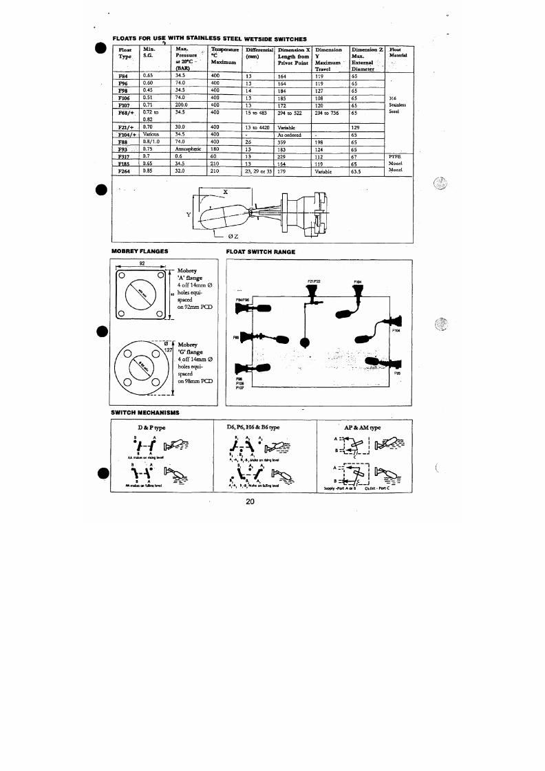
7/18/2019 M14 Thermal Fluid
http://slidepdf.com/reader/full/m14-thermal-fluid 337/486
\ ^ *
' VJ i^
k
A
1
Jr
M OBREY F L ANGES F L OAT SWIT CH RANGE
A C C E S S O R IE S
a_
Test devices for Mo brey 'A'
flanged
switches to facilitate mechanical testing of electrical circuit
a r-
11
'T
TD lOOM (Sandwich)
1
ä
.-'_.
. . 1 .
i
c
•-e-
1
i -
TO
ioi/A(wad)
h
b —»j °rD102/10 & / 1 6 ( F l a i ^
Ty pe
T D 1 0 0 / A
T D I O I / A
T D 1 0 2 /1 0
TD 1 (^/1 6
Vesse l Flange
Mobrey'A'
Weld on
P N 1 0 D N 8 0
P N 1 6 D N 8 0
M ax. Pressure
Bar
1 8 "
18
10
16
Max.
Te mp.°C
c d
Ø n u n
120
120
120
120
120
85
200
200
35
64
85
85
155
155
155
155
-
92
92
92
-
-
21
21
67.5
67.5
67.5
67.5
No te: Maximum temperature can be increased to 210°C with Viton 'O ' ring. Please state when ordering.
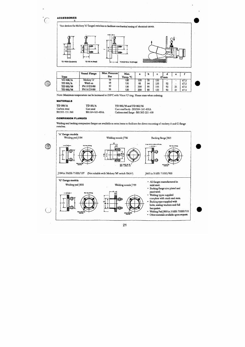
7/18/2019 M14 Thermal Fluid
http://slidepdf.com/reader/full/m14-thermal-fluid 338/486
MA TE R IA LS
T D 1 0 0 / A
Carbon steel
BS1501-151-360
T D I O I / A
Cast steel
BS1504-161-430A
T D 102/10 and TD 102/16
Cast steel body-B S1504-161-430A
Carb on steel
flange
BS 1 5 0 3 -2 2 W 3 0
A P P L I C A T I O N S
V
g
A LA R M D U TY
Perhaps the most common application for the original Mobrey float switch is liquid
level dete ction for alarm duty. W hethe r for high or low alarm,
th e
" M o b r e / '
is
on e
of
the mo st reliable and cost effective in strum ents available today Using the time
prov en princip le of magnetic coupling, the switch is gjandlcss, snap-acting and
suitable for almos t any
liquid.
Manufactured w ith a range of wetside m aterials and
with a choice of electrical or pneumatic output, side or top mounting models have a
tough IP6 6 weatherproof housing and are flange moun ted to provid e the "fit and
forget" so lution for liquid level alarm.
R u ^ e d , Rel iable, Glandless , Weatherproof
P U M P C O N T R O L
Mobrey sw itches m aybe specified with pump control float mechanisms which can be
site adjusted to give contro l ove r the required liquid differential. Side m oimtin g
models ope rate ov er 500mm —ideal for small hea der o r filling tanks, and vertical
mo unting m odels with cüfferenrials up to 450 0m m are commonly used in sumps
and storage tanks.
Side mou nt , Top m oun t. Site iadjustable
S U B M E R S E D A P P L I C A T I O N S
If it is no t possible to side or top mou nt a switch, then specify the Submersible m od el
This switch is watertight IP6 8 to 30m sub mersion, an d may be tank floor mounted to
provide low level alarm or pum p cut-off/pu mp protection in sumps and pits. For
heavily fouled liquids, a shro ude d m odel
is
ideal as all the moving p arts are pro tected
inside an and-fouling shroud. Switches may be supplied with or without factory fitted
and tested cable, with the option of Rubber or copper Pyrotenax cable to suit.
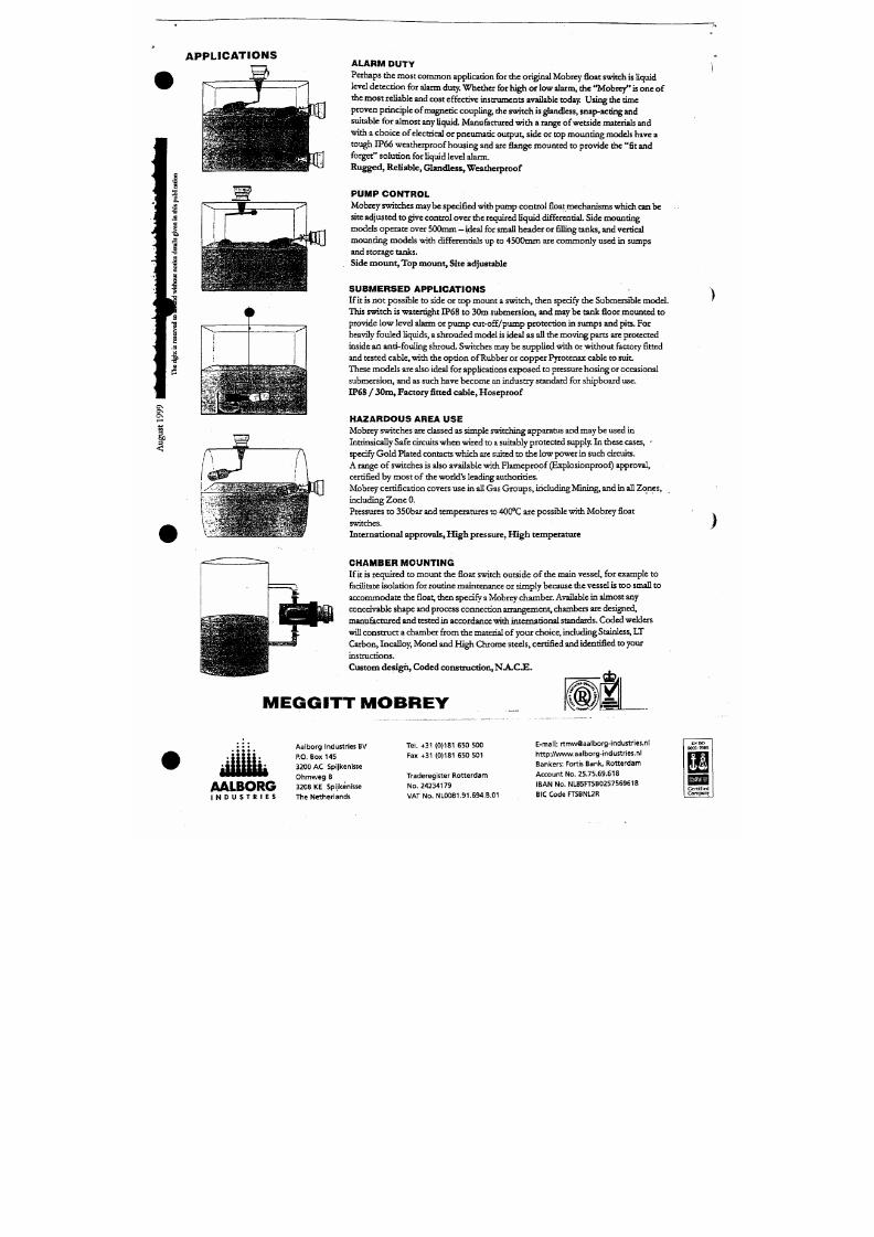
7/18/2019 M14 Thermal Fluid
http://slidepdf.com/reader/full/m14-thermal-fluid 339/486
These m ode ls are also ideal for applications exp ose d to pressure ho sing or occasional
submersion, and as such have become an industry standard for shipboard use.
IP68
/ 30nQ, Fac tory
fitted cable, Hoseproof
H A ZA R D O U S A R E A U S E
AALBORG
I N D U S T R I E S
Aalborg Industr ies NL BV
P
O Box 145
3200 AC Spijkenisse
Ohmweg 8
3208 KE Spijkenisse
Tl ie Netherlands
0
•* I i ^ - ^m
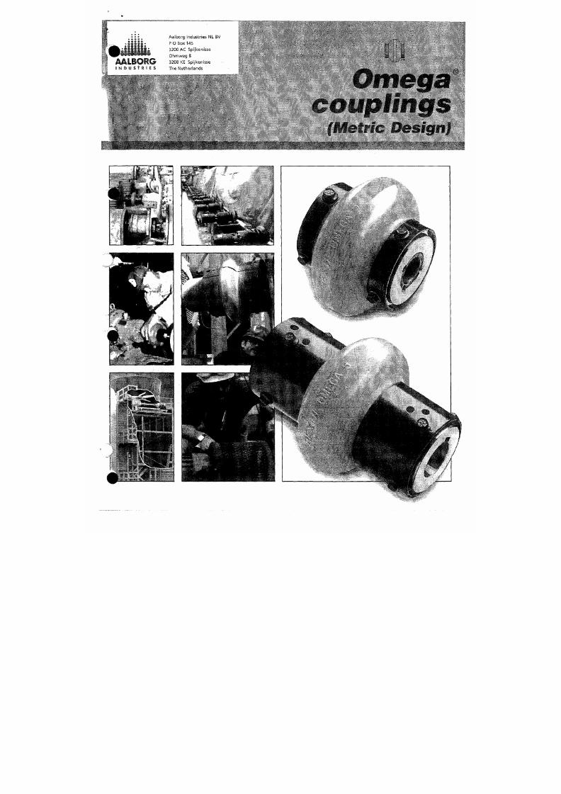
7/18/2019 M14 Thermal Fluid
http://slidepdf.com/reader/full/m14-thermal-fluid 340/486
REX OMEGA COUPLINGS
N O O T H E R C O U P L I N G C A N O F F E R
A L L T H E S E F E A T U R E S & B E N E F I T S
r i f i f
W
Features
Benefits
Split-In-Half Flex Element Design
Polyurethane Flex Element
Torsionally Soft
High M isalignment Capacity
Visua l Inspection
Interchangeable Hubs
Adjustable Spacer
Easy replacement without moving the hubs or connected equipment
No lubrication required, excellent ch emical resistance
Protects equipment by cushioning shock loads and torsional v ibration
Accommodates unavoidable misalignment with low reactionary forces
No need for coupling disassem bly to inspect
Standard and spacer cou pling hubs are identical
One spacer coupling size can accom mod ate different shaft separations
Rex Omega Standard Coupl ing
standard "close coupled" design available in 15 sizes covering
applications up to 48,000 Nm torque a nd bores up to 229mm.
Rex Omegja Spacer Coupl ing
Spacer design available In 12 sizes covering applications up to
5,580 Nm torque and bores up to 155mm.
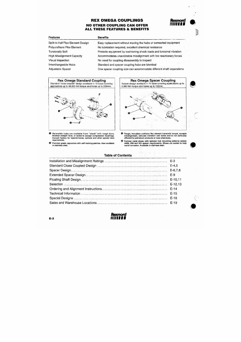
7/18/2019 M14 Thermal Fluid
http://slidepdf.com/reader/full/m14-thermal-fluid 341/486
Ifffif
REX OMEGA COUPL INGS
I N S T A L L A T I O N . . . A S S I M P L E
AS
P E E L I N G A N O R A N G E
Mount one hu b to shaft, leave other
hub loose for adjustment of spacing.
#
Place ha l f of the O me g a e le me n t
a round hubs and secure wi th sel f-
locking capscrews. Omega e lement
will space the other hub. Now secure
the other hub.
T e s te d T o u g h
Rigorous testing demonstrates that the
Rex O mega coupling protects connected
equipment from the damaging effects of
misa l ignment , v ib ra t ion , and g ross
overload.
Where other coupling designs
Mount o ther ha l f of the O m e g a
e lement . T igh ten al l ca p sc r e ws to
recommended torques (below) and
you're don e
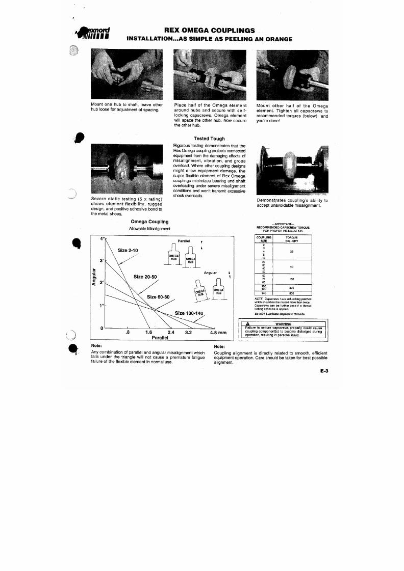
7/18/2019 M14 Thermal Fluid
http://slidepdf.com/reader/full/m14-thermal-fluid 342/486
might al low equipment damage, the
super flexible element of Rex Omega
couplings minimizes bearing and shaft
overloading under severe misalignment
conditions and won't transmit excessive
OMEGA STANDARD COUPLING
With Straight Bore Hubs
%
Note: l-lub/shoulder
design
varies per coupling size.
Consult Rexnord for spe
cific size assembly draw
ings.
(Hubs Outboard)
(Hubs Inboard)
ü
Specification Data With Straight Bo re Hubs
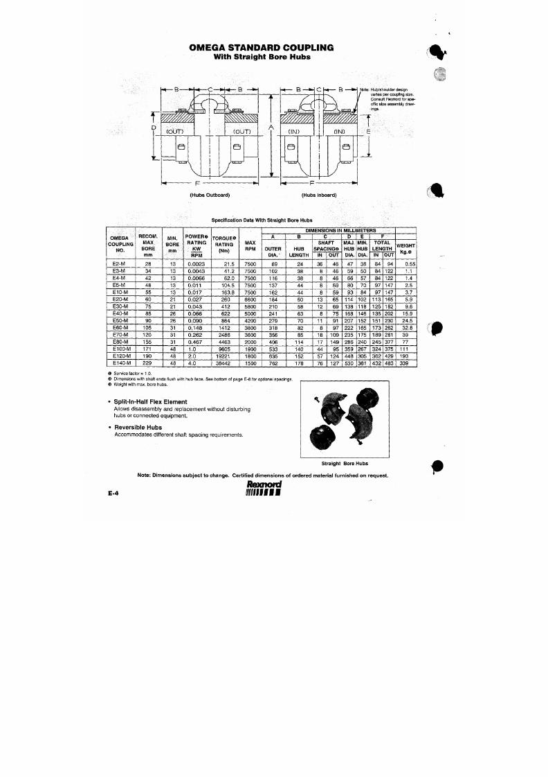
7/18/2019 M14 Thermal Fluid
http://slidepdf.com/reader/full/m14-thermal-fluid 343/486
OMEGA
COUPLING
NO.
E 2- M
RECOM.
MAX.
BORE
mm
28
MIN.
BORE
mm
13
P OWE RO
RATING
KW
RP M
0.0023
TORQUE©
RATING
(Nm)
21.5
MAX
RPM
7500
DIMENSIONS IN MILLIMETERS
A
OUTER
DIA.
-
89
B
HUB
LENGTH
24
C
SHAFT
SPACING©
IN
36
OUT
4 6
D
MAJ.
HUB
DIA.
47
E
MIN.
HUB
DIA.
38
F
TOTAL
LENGTH
IN
8 4
OUT
94
WEIGHT
Kg.©
0.55
OMEGA STANDARD COUPLINGS
With Compression Buslied Hubs
Specification Data Witii TAP ER-LOCK™ Hubs
RECOM.
POWER©
DIMENSIONS IN MILLIMETERS
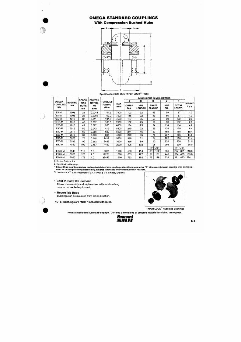
7/18/2019 M14 Thermal Fluid
http://slidepdf.com/reader/full/m14-thermal-fluid 344/486
OMEGA
COUPLING
NO.
E3-iVl
:E 4 -M
BUSHING
NO.
1008
1008
MAX
BORE
mm
25
25
RATING
KW
RPM
0.0043
0.0066
TORQUE©
RATING
(Nm)
41.2
62.0
MAX
RPM
7500
7500
A
OUTER
DIA.
102
116
B
HUB
LENGTH
2 2
2 2
C
SHAFT
SPACING
43
43
D
HUB
DIA.
59
66
F
TOTAL
LENGTH
87
87
WEIGHT
Kg .«
1.0
1.3
OMEGA SPACER COUPLING
With Straight Bore Hubs
Note: Hub/shoulder design
varies per coupling size.
Consu lt Rexnord for spe
cific size assembly draw
ings.
OMEGA
COUPLING
NO.O
ES2-R-M
RECOM.
MAX
BORE
mm
28
MIN.
BORE
mm
13
POWER
RATING
KW
RPM®
0.0023
Specifica tion Data With Stra ight
TORQUE
RATING
(Nm)@
21.5
MAX
RPM
®
7500
Bore Hubs
DIMENSIONS
IN
MILLIMETERS
A
OUTER
DIA.
89
B
HUB
LENGTH
24
C
SHAFT
SPACINGO
MIN
91
MAX
100
D
MAJ.
HUB
DIA.
47
E
MIN.
HUB
DIA.
38
F
TOTAL
LENGTH
MiN.@
146
MAX
149
W EI GH T
K g . ®
1.0
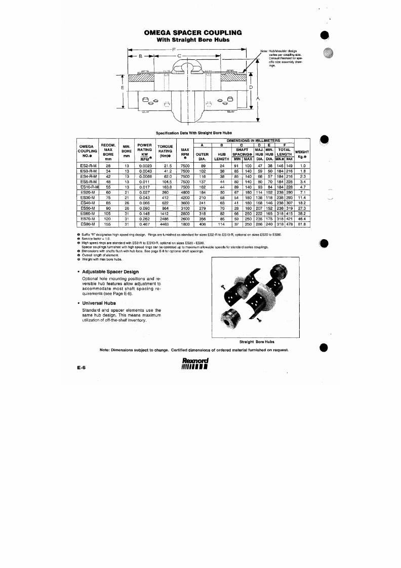
7/18/2019 M14 Thermal Fluid
http://slidepdf.com/reader/full/m14-thermal-fluid 345/486
ES3-R-M
ES4-R-M
ES5-R-M
ES10-R-M
ES20-M
34
42
48
55
60
13
13
13
13
21
0.0043
0.0066
0.011
0.017
0.027
41.2
62.0
104.5
163.8
260
7500
7500
7500
7500
4800
102
116
137
162
184
38
38
44
44
50
85
85
89
89
67
140
140
140
140
180
59
66
80
93
114
50
57
70
84
102
184
184
184
184
238
216
216
228
228
280
1.8
2.3
3.4
4.7
7.1
OMEGA SPACER COUPLINGS
With Compression Bust led Hubs
OIVIEGA
COUPLING
NO.O
BUSHING
NO.
RECOM.
MAX
BORE
mm
Specification Data With TAPE R-LOCK™ Hubs
POWER
RATING
KW
TORQUE©
RATING
(Nm)
MAX
RPM
@
DIMENSIONS IN MILLIMETERS
A
OUTER
DIA.
B
HUB
LENGTH
C
SHAFT
SPACINGO
MIN. MAX
D
HUB
DIA.
F
TOTAL
LENGTH
MIN.
MAX
WEIGHT
Kg.©
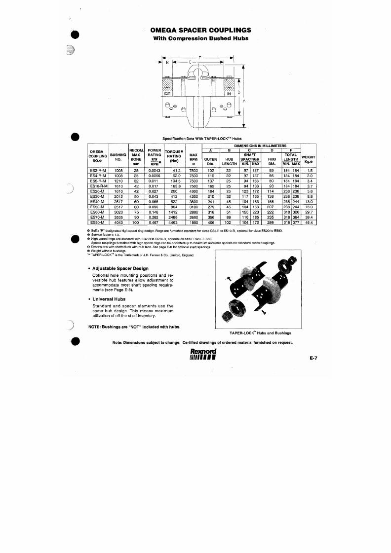
7/18/2019 M14 Thermal Fluid
http://slidepdf.com/reader/full/m14-thermal-fluid 346/486
ES3-R-M
ES4-R-M
ES5-R-M
ES10-R-M
1008
1008
1210
1610
25
25
32
4 2
RPM®
0.0043
0.0066
0.011
0.017
41.2
62.0
104.5
163.8
7500
7500
7500
7500
102
116
137
162
22
22
25
25
97
97
94
94
137
137
133
133
5 9
66
80
93
184
184
184
184
184
184
184
184
1.5
2.0
3.4
3.7
O M E G A S P A C E R C O U P L I N G " A D J U S T A B I L I T Y "
Shaft Spacing Possibi l i t ies
(Using Straight Bored Hubs)
The Omega spacer coupling design provides a clear space between hubs. The element is split longitudinally and there are no
interfering center members or spools. Thus, shaft spacings as small as 6 mm can be achieved by recessing the hubs on the
shaft (see Figure F below). However, for such small spacings, use of the standard Omega coupling would be recommended.
The maximum shaft spacing ("C" dimension) for each coupling is shown on page E6 and E7. However any ANSI, ISO or DIN
spacing between 6 mm and the m axim um listed can be achieved without any additional parts. Hubs can be placed on the shafts
as shown below.
Figure A
Both hubs mounted outward
Figure B
One hub mounted Inward
One hub mounted outward
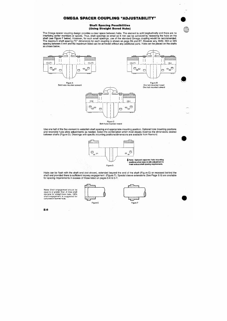
7/18/2019 M14 Thermal Fluid
http://slidepdf.com/reader/full/m14-thermal-fluid 347/486
Rsxnord
i/fffffl
OMEGA EXTENDED SPACER COUPLING
Omega extended spacer couplings are designed to connect equipment with shaft spacing requirements beyond the Omega
spacer coupling capabil i t ies. They are ideal for applications with wide non-standard shaft gaps, and can be an economic
alternative to floating shaft couplings (i.e. stock pump applications).
Sleeve extensions
("SE")
are furnished in steel. They mount to regular Omega spacer elements (standard elements for sizes
E l 00 & El2 0) and cast iron or steel hubs — straight bore or com pres sion bu shed des ign. By adjusting the hub/shaft
engagement (see f igures E & F on page E-8) and spacer element mounting posit ion, the Omega extended spacer coupling
can be utilized for many shaft spacing requirements.
'Z/^'///.
^-
^
r m
^ ? ^ % : ^ 5 ^ ^
0
® e
— C
V
/
j^K^j^yf,
e e ®
^.fCT.
F=Ci
^5n-l
, \ , , x -
&
Single Extension
Maximum Spacing O
Double Extension
" C" Dimension - Millimeters
SPACER
MAX
RPM
MAX RPM©
MATCHED
WITH SHRB / SHRB HUBS With HTUHTL Hubs
WEIGHT
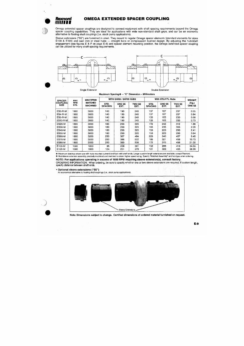
7/18/2019 M14 Thermal Fluid
http://slidepdf.com/reader/full/m14-thermal-fluid 348/486
COUPLING
SIZE
ES3-R-M
ES4-R-M
E S 5 -R-M
STD.
1800
1800
1800
MACHINED
3600
3600
3600
STD.
SPACING
140
140
140
O N E S E
EXT.
190
190
190
T W OS E
EXT.
240
240
240
STD.
SPACING
137
137
133
ONE S E
EXT.
187
187
183
T W OS E
EXT.
237
237
233
(Kg.)
ONE S E
0.55
0.84
0.68
OM E GA P ILOTE D
FLOATING S HAFT COUPLINGS
Super Flexible Polyurethane Elements:
Protects equipment from the damaging effects of misalignment
and shock loads. Elements are split longitudinally for easy
assembly/disassembly.
Specially Designed Capture Feature:
Minimizes chances for catastrophic fai lures result ing from
fatigue or excessive misalignment.
Option al Center IVIembers:
Steel ,
stainless steel or composite materials are avai lable
depending on application and environmen tal requirements.
No Lubrication:
Pi lo t bush ing and po lyure thane e lement do not requ i re
lubrication.
Corrosion Resistance:
Zinc plated steel, stainless steel, composite material, or acid
and alkali protective coatings a re available.
Long Span Capability:
Optional composi te tubes al low s igni f icant ly longer span
capabilities than conve ntional steel tubes.
Rex Omega Piloted f loating shaft couplings are uti l ized to
connect equ ipment wh ich i s re la t i ve ly fa r apar t . Such
arrangements are particularly suited to transmit torque into
areas where moisture, dust or corrosive conditions would be
detrimental to driving machinery.
Typical applications Include cooling tower drives, steel mill roll
drives and paper machine drives®.
The Omega coupling's floating center member may be either
solid or tubular, depending upon the system requirements. The
assembly is piloted at each end by a resilient rubber bushing
assembly which eliminates the need for intermediate support
bearings.
Besides reliability, safety was engineered into the design by
incorporation of the captured center member feature, which
minimizes the possibility of a catastrophic failure due to fatigue
or severe misalignment.
Omega Pi loted f loat ing shaft coupl ings are designed to
alleviate situations where excessive misalignment in cooling
tower applications are trouble-some.
Self aligning:
Omega Piloted Floating
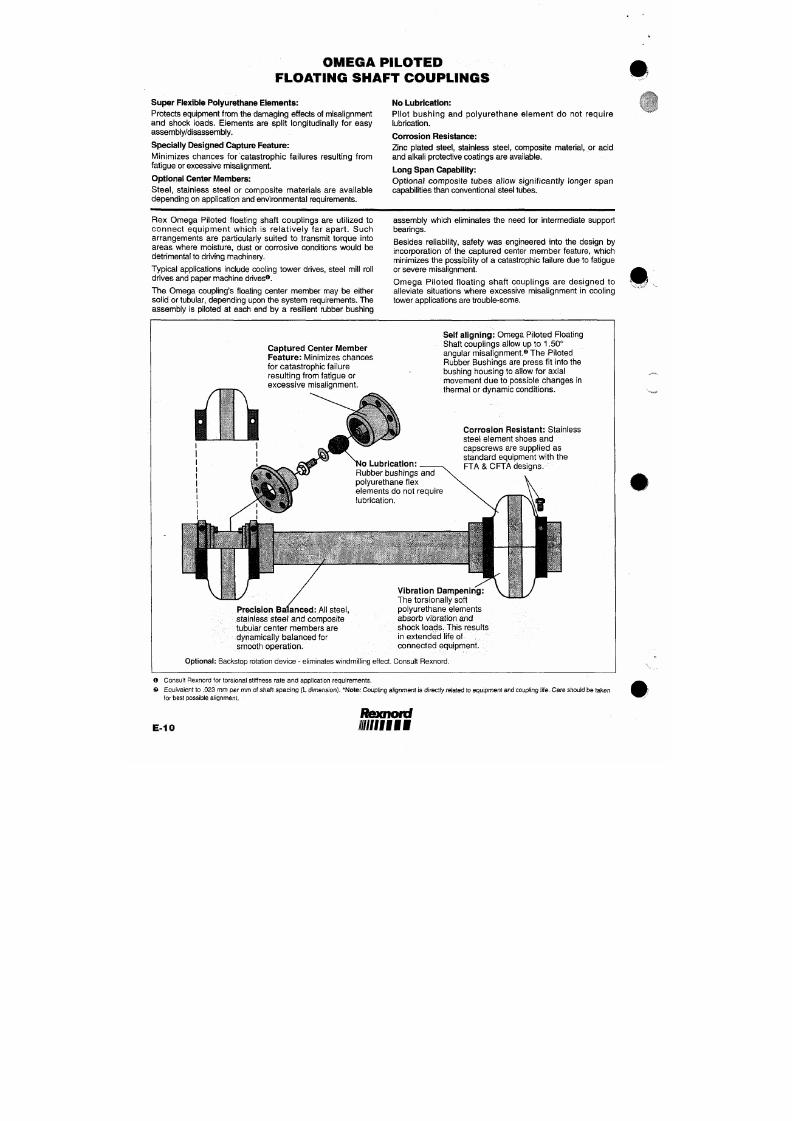
7/18/2019 M14 Thermal Fluid
http://slidepdf.com/reader/full/m14-thermal-fluid 349/486
Captured Center iUlember
Feature:
M inimizes chances
for catastrophic failure
resulting from fatigue or
Shaft couplings allow up to 1.50°
angular misalignment.® The Piloted
Rubber Bushings are press fit into the
bushing housing to allow for axial
movement d ue to possible chang es in
OM E GA P ILOTE D
FLOATING SHAFT COUPLINGS
(COOLING TOWER DRIVE COUPLINGS)
Floating Tubular Assembly
( F T A )
Ome ga Composite Floating Tubular Assembly
(CFTA)
SPECIFICATION DATA
Omega
Size
No.
E10-M
E20-M
E30-M
E40-M
PowerO
Rating
KW
RPM
0.017
0.027
0.043
0.066
Torque©
Capacity
(Nm)
164
260
412
622
Max
RPIVI
1800
1800
1800
1800
Max@
Bore
(mm)
5 5
60
75
85
Dimensions
(mm)
A
162
184
210
241
B
43
4 8
5 4
5 9
Minimum
Span
(L)
mm
213
251
267
292
Maximum Span (L) in mm
@Ma x RPM@
Steel
FTA
1905
2 1 59
2286
2540
Composite
(CFTA)
2642
2642
3277
3277
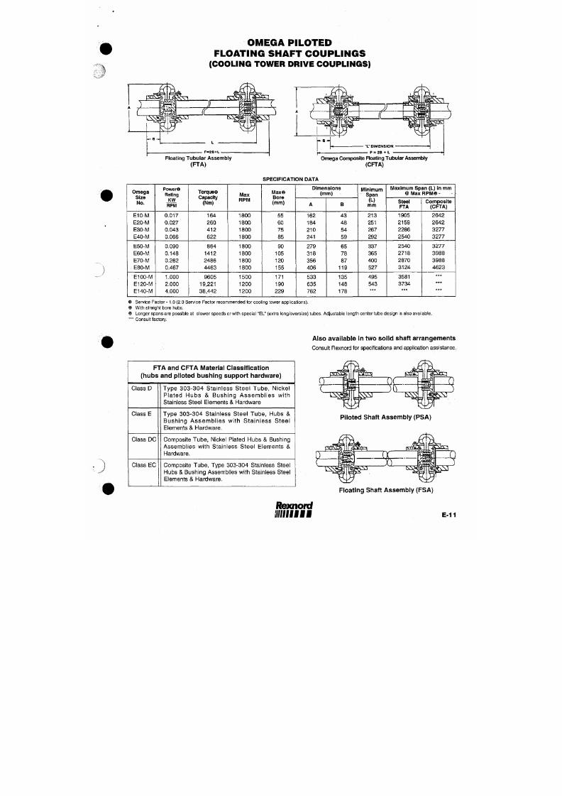
7/18/2019 M14 Thermal Fluid
http://slidepdf.com/reader/full/m14-thermal-fluid 350/486
E50-M
E60-M
E70-M
E80-M
0.090
0.148
0.262
0.467
864
1412
2486
4463
1800
1800
1800
1800
90
105
120
1 55
279
318
356
406
65
78
87
119
337
365
400
527
2540
2718
2870
3124
3277
3988
3988
4623
COUPLING SELECTION
SELECTION PROCEDURES
1.
Calculate KW/RPM
2.
Determine service factor from table on page E-13. If not l isted,
see load classification table below. Remember
to
consider both
driver and driven equipment and tempe rature limitations.
3 . Mu l t i p l y KW/RPM
by the
se rv i ce fac to r
to get
equivalent
KW/RPM.
4.
Select coupl ing size from Table
1
with
a
rat ing equal
to or
greater than
the
equivalent KW/RP M determined
in
step
3.
5.
Be
sure that
the
operat ing speed
of the
coupl ing does
not
exceed maximum RPM ratings.
6. Select desired hub type from descript ion on page E-14. Check
maximum allowable coupling bore.
OR
Table
1
Size
standard
E2
E3
E4
E5
E10
E20
E30
E40
E50
E60
E70
E80
El 00
E120
El 40
Spacer
ES2
ES3
ES4
ES5
ES10
ES20
ES30
ES40
ES50
ES60
ES70
ES80
NA
NA
NA
KW/RPM
0.0023
0.0043
0.0066
0.011
0.017
0.027
0.043
0.066
0.090
0.148
0.262
0.467
1.0
2.0
4.0
1. Calculate operating torque
KW
RPM
(9550)
2.
Multiply operating torque by service factor obtained from table
on page
E-13.
3. Select coupling size from Table
2
with
a
capacity equal
to or
greater than determined
in
step
2.
4.
Follow steps
5 and 6
above.
Table
2
Size
2
3
4
5
10
TORQUE CAPACITY
Torque (Nm)
21.5
41.2
62
104.5
163.8
Size
40
50
60
70
80
100
Torque (Nm)
622
864
1412
2486
4463
9605
H P
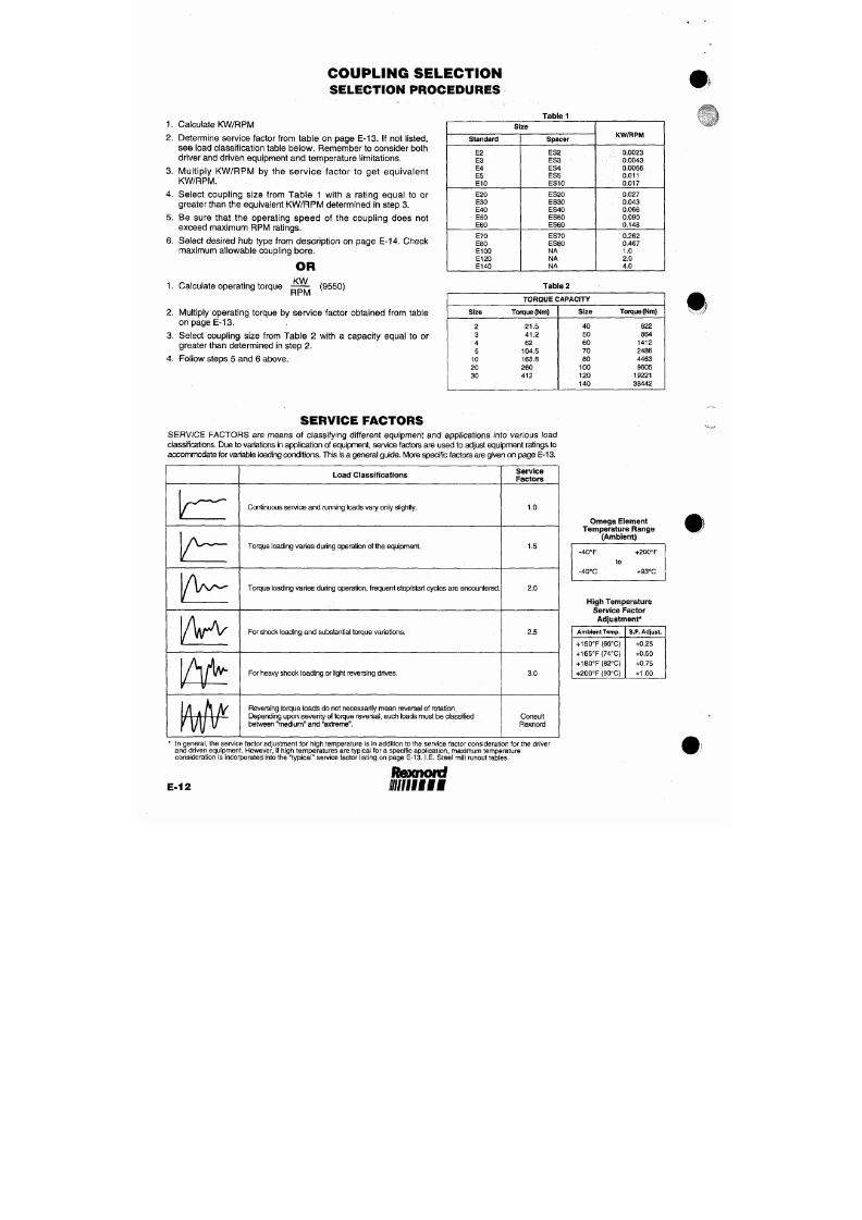
7/18/2019 M14 Thermal Fluid
http://slidepdf.com/reader/full/m14-thermal-fluid 351/486
20
30
260
412 120
140
19221
38442
Rexnoid
//////ffffii
COUPLING S E LE CTION
TYPICAL SERVICE FACTORS*
—
MOTOR
AND
TURB INE DRIVEN EQUIPMENT
General Applications
Typical
Service Factor
Industry Applications (cont'd)
Typical
Service Factor
AGITATORS
Vertical and Horizontal Screw Propeller, Paddle 1.5
BLOWERS
Centrifugal 1.0
Lobe or Vane 1.5.
CAR DUMPER AND PULLER 2.0
CLARIFIER
OR
CLASSIFIER
1.0
COMPRESSORS
Centrifugal ,. 1.0
Rotary, Lobe or Vane 2.0
Rotary, Screw 1.25
Reciprocating **
CONVEYORS
Apron,
Assem bly, B elt. Chain Fl igti t, Oven 1.5
Reciprocating **
Screw 1.25
CRANES AND HOISTS
Main Hoist — IVledium Duty 2.0
Main Hoist •— Heavy Duty 2.5
Skip Hoist 2.0
Bridge, Travel
or
Trolley
2.0
DREDGES
Cable Reel, Conveyor
2.0
Cutter Head Drive, Jig Drive 3.0
Pump, Screen, Drive, Stacker, Utility V^inch 2.0
DYNAMOMETER
1.0
ELEVATORS
Bucket, Freight 2.5
FOOD INDUSTRY
Bottle and Can Filling
1.0
Cereal Cooker 1.0
Dough Mixer, Meat Grinder 2.0
LUMBER INDUSTRY
Band Resaw, Circular Resaw 2.0
Edger,
Head Rig,
Hog, Log
Haul
2.5
Planer 2.0
Rolls, Non-Reversing 2.0
Rolls,
Reversing. 2.5
Sawdust Conveyor 1.5
Slab Conveyor, Sorting Table 2.0
OIL INDUSTRY
Chiller 1.0
POWER INDUSTRY
Ash Handling Conveyors 1.5
Baghouse Air Handling Fans 1.5
Ball Mill 2.5
Belt Conveyors
1.5
- Circulating Pumps (centri fugal) -.: 1.0
Coal Grinders
and
Crushers
2.5
Coal Pulverizers an d Hammerm il ls 2.5
Cooling Tower Fans
2.0
FGD Slurry Pumps (centri fugal) 1.0
Forced Draft Fan and Induced Draft Fan 1.5
Primary Air, Recycling Fans 1.5
Traveling Water Screens 1.0
PULP & PAPER MILLS
Agitator 1.5
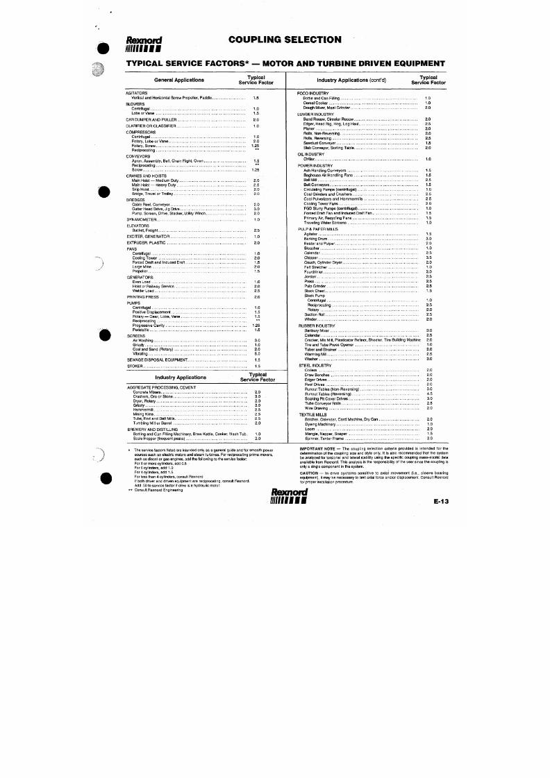
7/18/2019 M14 Thermal Fluid
http://slidepdf.com/reader/full/m14-thermal-fluid 352/486
EXCITER, GENERATOR 1.0
EXTRUDER, PLASTIC 2.0
FANS
Centrifugal 1.0
Cooling Tow er
2.0
Forced Draft and Induced Draft 1.5
Barking Drum 3.0
Beater and Pulper 2.0
Bleacher 1.0
Calendar 2.5
Chipper
3.5
Couch, Cylinder Dryer 2.0
OR D E R IN G IN S TR U C TION S
S T A N D A R D AND S P A C E R C O U P L I N G S
When ordering
a
complete coup ling, specify size/type
of
element
and
hubs
(two
hubs
per
complete coupling) options include:
Element
—
[E2-M
-
E140-M] standard (close coupled)
[ES2-R-M
-
ES80-M] S PACER
[2MSHRB - 140M SHR B] straight hub-rough bore
Hub
—
[2MSHCB
-
140MSHCB] straight hub-custom bore (specify bore
&
keyway)
[3MHTI -140MHTL ] hub-TAPER-LOCK" (bushing not included)
OTHER AVAILABLE DESIGNS (Consul t Rexnord)
Sleeve Extens ion s
—
[3SE
-
120SE]
[10FTA
-
140FTA] specify bore, shaft spacing
&
material class
Float ing Pi lo ted Shaf t Coupl ings — [10PS A-14 0PS A] specify bore, shaft spacing & material class
[1OFSA -140F SA ] specify bore, shaft spacing & material class
GE N E R A L A L IGN M E N T IN S TR U C TION S
C A L I P E R
AND
S T R A I G H T E D G E M E T H O D
EQUIPMENT ALIGNMENT
Coupling alignment is directly related to equipment and coupling life.
Although Omega couplings can withstand gross misalignment, care should be taken for best possible alignment to assure
optimum performance.
The
caliper/straightedge alignment procedure
is
described below.
If
greater alignment accuracy
is
desired,
a
dial indicator m ethod
is
recommended. There
are
occasions when equipment manufacturers require more specific
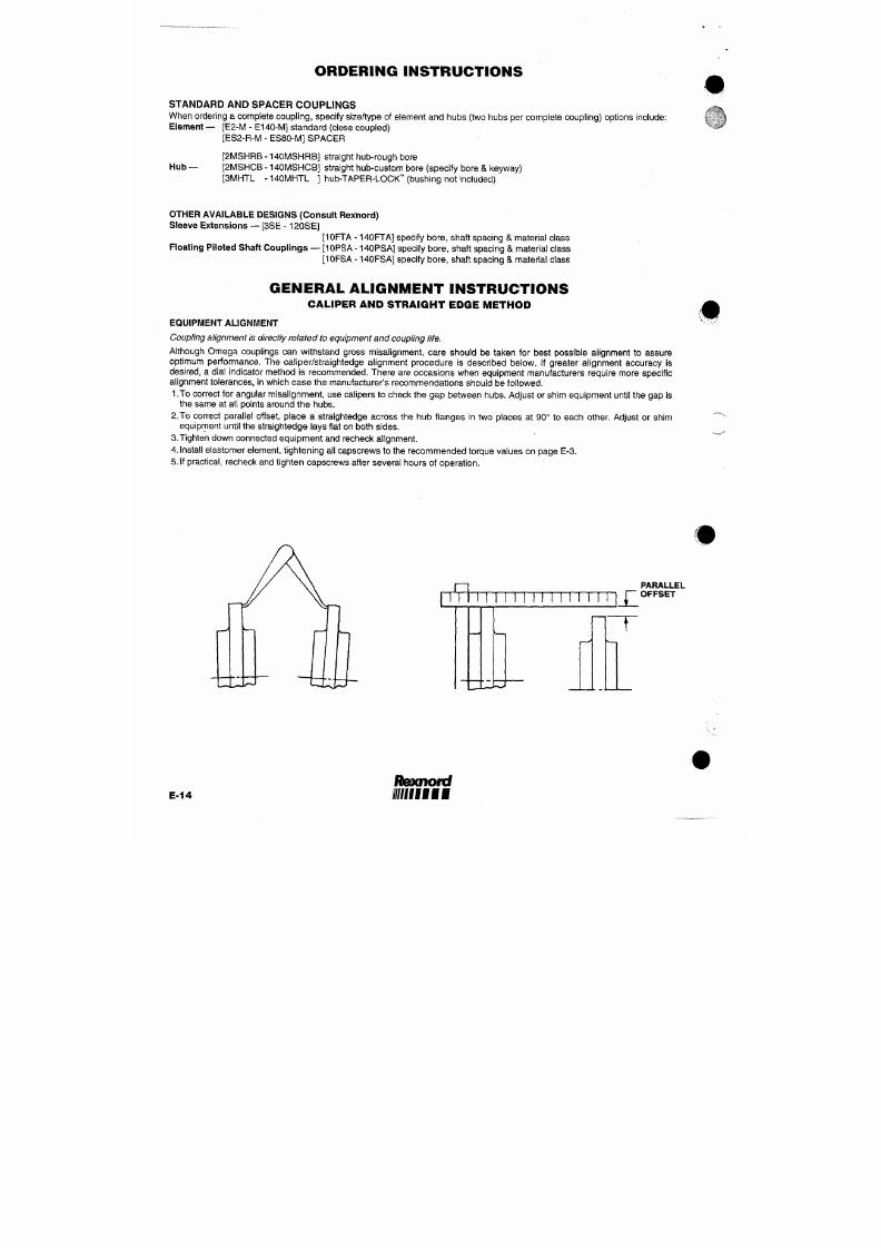
7/18/2019 M14 Thermal Fluid
http://slidepdf.com/reader/full/m14-thermal-fluid 353/486
alignment tolerance s,
in
which cas e
the
manufacturer's recommendations should
be
followed.
1 .To correct
for
angular misalignment,
use
calipers
to
check
the gap
between hubs. Adjust
or
shim equipment until
the gap is
the same
at all
points around
the
hubs.
2.To correct parallel offset, place
a
straightedge across
the hub
f langes
in two
places
at 90° to
each other. Adjust
or
shim
TECHNICAL INFORMATION
P h y s i c a l P a r a m e t e r s
Cplg.
Size
E2
ES2-R
E3
ES3-R
E4
ES4-R
E5
ES5-R
E10
ES10-R
E20
ES20
E30
ES30
E40
ES40
Norn.
Torque
(Nm)
21.5
41.2
62.0
104.5
163.8
260
412
622
Max
Torque
(Nm)
53.8
103.0
155.0
261.3
409.5
650
1030
1555
Max
Speed
(RPM)
7500
7500
7500
7500
7500
7500
7500
7500
7500
7500
6600
4800
5800
4200
5000
3600
Moment
of Inertia
J
(Kgm=)
.000323
.000528
.000733
.001670
.001230
.002670
.003230
.005860
.006450
.009970
.016100
.021100
.033700
.044000
.080600
.100000
Max
Axial
Misalign
(mm)
4.7
4.7
4.7
6.3
6.3
6.3
6.3
6.3
Max
Radial
Misalign
(mm)
1.6
1.6
1.6
1.6
1.6
2.4
2.4
2.4
Max
Angular
Misalign
rad
.070
.070
.070
.070
.070
.052
.052
.052
deg
4
4
4
4
4
3
3
3
Static**
Torsional
Stiffness
(Nm/rad)
433
842
777
1490
1750
2460
4855
7315
Static**
Axial
Stiffness
(N/mm)
105
114
123
181
251
272
280
314
Static**
Radial
Stiffness
(N/mm)
226
235
245
264
468
482
503
522
Static**
Angular
Stiffness
(N/rad)
102
133
175
264
654
822
971
1754
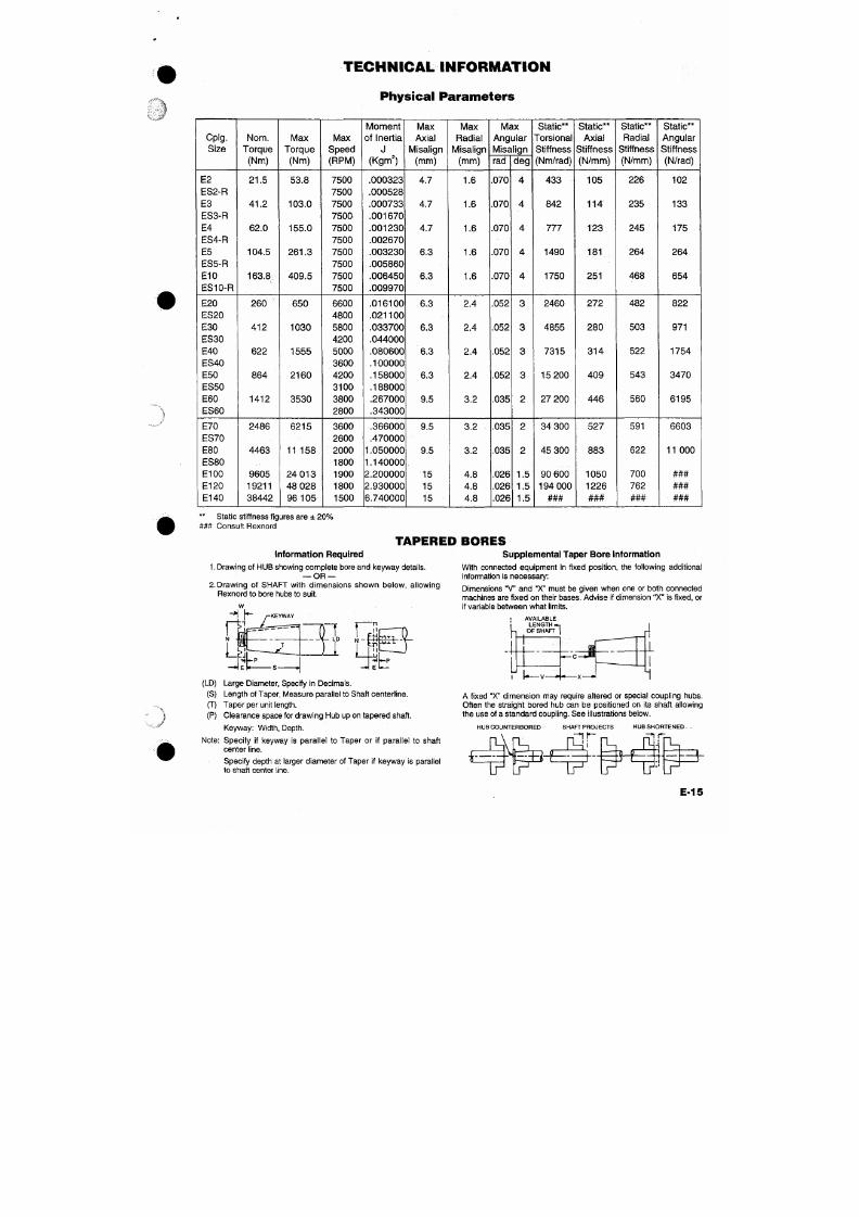
7/18/2019 M14 Thermal Fluid
http://slidepdf.com/reader/full/m14-thermal-fluid 354/486
E50
ES50
E60
ES60
864
1412
2160
3530
4200
3100
3800
2800
.158000
.188000
.267000
.343000
6.3
9.5
2.4
3.2
.052
.035
3
2
15 200
27 200
409
446
543
560
3470
6195
Rexnofd
i/ffllffl
S P E C I A L D E S I G N S '
Stainless
Steel
O m e g a S t a i n l e s s S t e e l E l e m e n t
Corrosion resistant stainless steel shoes
for severe environments i.e: cooling towers.
Stainless steel hubs & capscrews also available.
O meg a M i l l Co u p l i n g s
Tapered hub design for mill motor applications,
(i.e.,
steel mill roll table drives).
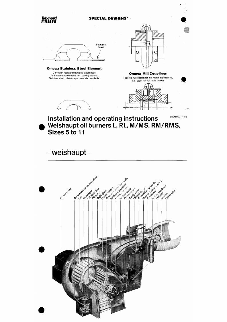
7/18/2019 M14 Thermal Fluid
http://slidepdf.com/reader/full/m14-thermal-fluid 355/486
8 3 0 4 0 2 0 2 - 1 / 9 9
Installation and operating instructions
Weishaupt oil burners L, RL, M /M S . R M /R M S ,
Sizes 5 to 11
weishaupt-
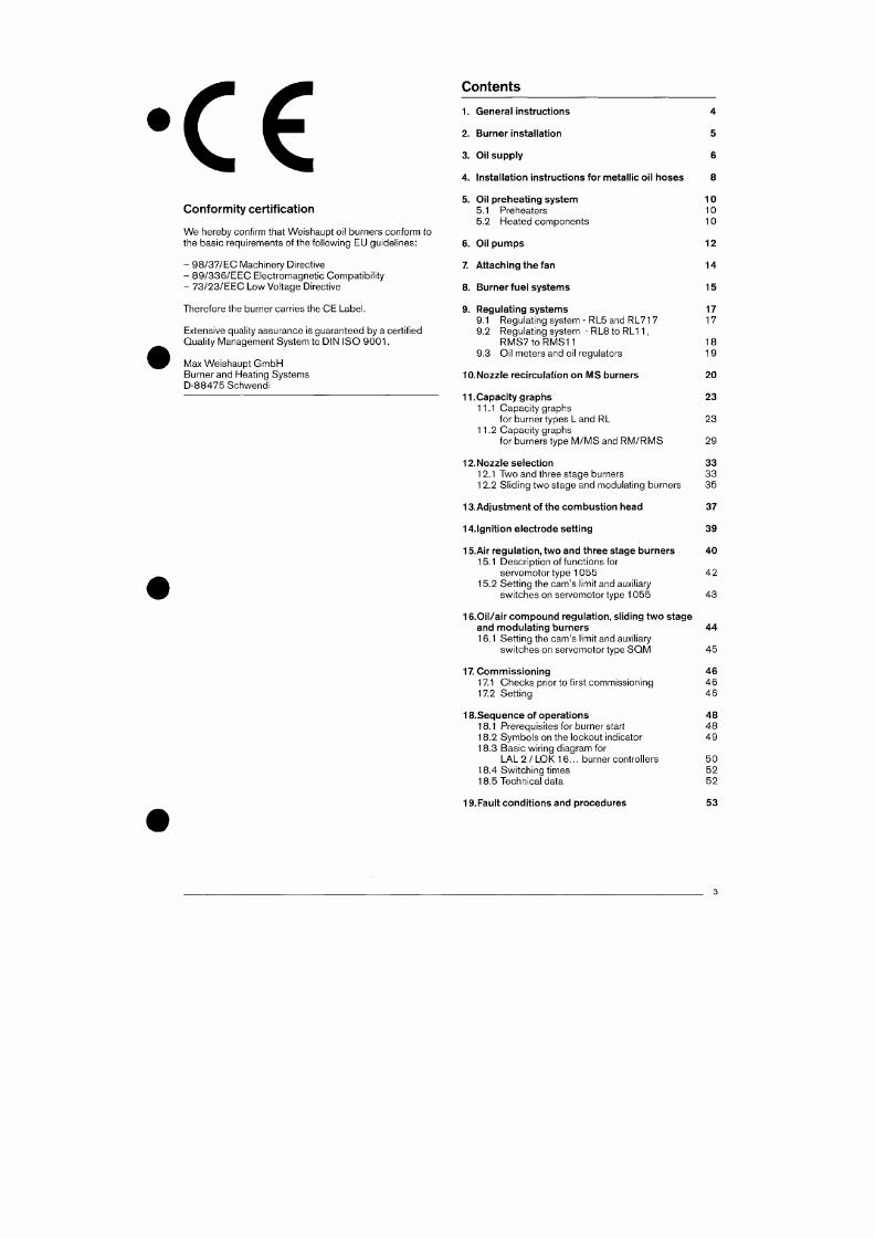
7/18/2019 M14 Thermal Fluid
http://slidepdf.com/reader/full/m14-thermal-fluid 356/486
Contents
Con formity ce rt if ication
W e hereby conf i rm that Weishau pt oi l burners conform to
the basic requirements of the following EU guidelines:
- 98/37/EC Machinery Direct ive
- 89/336/EEC E lec t romagnet ic Compat ib i l i t y
- 73/23/EEC Low Voltage Direct ive
Therefore the burner carries the CE Label.
Extensive quality assurance is guaranteed by a cert if ied
Qual i ty M anagement System to DIN ISO 9 0 0 1.
Max Weishaupt GmbH
Burner and Heat ing Systems
D-88475 Schwend i
1. Ge ner al instructions 4
2.
Burner installation 5
3. Oil supp ly 6
4. Installation instructions for metallic oil hose s 8
5. Oi l prehea ting system 10
5.1 Prehe aters 10
5.2 Hea ted comp onen ts 10
6. Oi l pum ps 12
7. Attaching the fan 14
8. Burner fuel systems 15
9. Regulat ing systems 17
9.1 Regula ting sys tem -R L5 and RL71 7 17
9.2 Regulat ing system - RL8 to RL 11 ,
R M S 7 t o R M S 1 1 1 8
9.3 Oil meters and oil regulators 19
10 .No zzle recirculation on M S burners 20
11.Capacity graphs 23
11.1 Capacity graphs
for burner types L and RL 23
11.2 Capacity graphs
7/18/2019 M14 Thermal Fluid
http://slidepdf.com/reader/full/m14-thermal-fluid 357/486
f o r bu rne rs t ype M / M S and RM / RM S 29
12 .
Noz zle selection 33
12.1 Two and three stage burners 33
1.
Genera l ins t ruc t ions
Safety
To ensu re safe burner operation, the burner has to be
instal led and comm issioned by qual i f ied personnel
and all guidelines in these operating instructions have
to be followed.
In particular, attention m ust be paid to relevant
installat ion and safety requirem ents (e.g. DIN, VDE ).
Flame monitoring devices, l imit controls, correcting
elem ents and all other safety devices m ay only be
com missione d by the m anufacturer or their authorised
agent.
Failure to comply can lead to serious injury or death
and can cause con siderable da ma ge to the plant.
Qual i f ied personnel
Quali f ied personnel according to this operating
ma nual are persons who are famil iar with the
installation, mounting, setting and commissioning of
the product and who have the neces sary qual if ications
such as:-
- P ersons who are trained to oper ate electrical
circuits and units to the safety standards given and
are qual i fied to earth and m ark the se.
Operating instructions
The operat ing inst ruct ions inc luded with ea ch burner must
Installation
The installat ion of oil f ired pla nt must be ca rried ou t in
accordance with extensive guidelines and regulat ions. I t is
the duty o f the installer to familiarise he r/himself w ith all
regulat ions. Instal lat ion, commissioning and maintenance
must be carried out with care. Fuel oils used must comply
with DIN
5 1
603 .
Electrical wiring diagram
A detailed electr ical wir ing diagram is included in every
burner delivery.
Maintena nce and service
In acco rdan ce w ith DIN 47 55 , the whole instal lat ion
including the burner should b e inspected o nce a year by a
representat ive of the manu facturer or a compe tent and
qual i fied perso n. The combu st ion f igures should be
che cked after every service and each t ime a fault has been
rect if ied.
Ambient requirements
The burners material, construct ion and type of protect ion is
designed for use indoors. The permissible ambient
temperature is -1 5°C to + 40 °C .
Electrical installation
W hen instal ling the elect r ical connect ion cables ensure
that these are long enough to allow the burner and boiler
door to be hinged open .
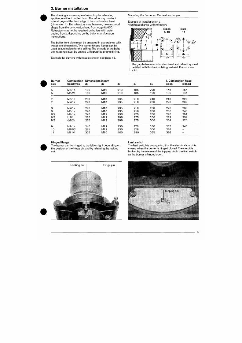
7/18/2019 M14 Thermal Fluid
http://slidepdf.com/reader/full/m14-thermal-fluid 358/486
be displayed clearly in the boiler room. In conjunction with
this we refer to DIN 4755, Point 5. The address of the
nearest service centre must be entered on the reverse side
of the operat ing instruct ions.
Control circuits, which are taken from one of the supply
phases, must only be con nec ted w ith an earthed neutral
conductor .
2. Burner installation
The dra win g is an examp le of refractory for a heating
appl ian ce w ithout coo led f ront . The ref ractory m ust not
extend beyo nd the f ront edge of the com bust io n head
(dimension IJ. The refractory may, however, take a conical
shape f rom the com bust ion head front edg e (> 60°).
Refractory may not be required on boilers with water
coo led f ronts, depe nding on the boi ler m anufacturers
inst ruct ions.
The boi ler f ront plate must be prepared in accordance with
the above dimensions. The burner hinged f lange can be
used as a temp late for the dri l l ing. The threa ds of the bo lts
and tapp ings must be coate d with graphite pr ior to f i tt ing.
Example for burners with head extension see page 13.
Moun ting the burner on the heat exchang er
Example of installat ion on a
heating appliance with refractory
S izes
5 - 1 0
The gap be tween com bust ion head and ref ractory must
be f i l led with f lexible insulat ing material. Do not make
solid.
Burner
size
5
5
7
7
Combust ion
head type
M5/ 1a
M 5 / 2 a
M 6 / 1 a
M7/ 1a
Dimensions in mm
d i
180
160
200
220
d2
M I O
M 1 0
M I O
M I O
d3
210
210
235
235
d4
185
185
2 1 0
210
ds
220
190
240
260
1 Combust ion head
open
145
130
216
226
closed
154
144
228
2 3 8
7/18/2019 M14 Thermal Fluid
http://slidepdf.com/reader/full/m14-thermal-fluid 359/486
8
8
8/2
M7 / 1a
M B / l a
M9 / 1a
220
240
240
M I O
M I O
M 1 2
235
235
2 9 8
2 1 0
2 1 0
275
260
280
280
226
236
226
238
248
251
3. Oil supply
Ope rat ional safety dep end s to a large degree on the oi l
supply. Pipe system layout and dimensions can be found in
our technical workshe ets.
Ring main system
The us e of a ring main system for oil sup ply to the burner is
recommended.
Note
The installat ion dependent r ing main pressure increases
the factory pre-set burner pump pressure.
Single pipe installation on request.
Suction lift operation
Suction l if t operat ion is possible for individual burners
operat ing on dist i l late oil EL. For installat ion and funct ional
diagrams for r ing main and suct ion l if t operat ion, see
technical worksheets 5
Strainer
A strainer is f it ted into the burner oil pipe wo rk (f low) to
prevent debr is , such as loosened swarf f rom the we lded
joints, from reaching the solen oid valves. The strainer
should be cleaned periodically, part icularly during init ial
operat ion.
Air /ga s separators
A Weishaupt air/gas separator should be f it ted at the point
at wh ich the burner two pipe system is conne cted. The
Termination of the oil sup ply pipes must allow tens ion free
connection of the f lexible oil hoses. Both oil and electr ical
conn ect ions must allow the burner to swin g open.
Pressure regulating valve in the ring main
Setting for oil EL
Ring main pressure 1 -1 .5 bar
Setting for oil S
To avoid vapo risat ion of wa ter in the fuel oil, the minimum
ring main pressure, including a safety margin, must be set
acco rding to the fol lowing table. It is based on the
pressure which is measured at the burner pump inlet (r ing
main pressure).
Oi l temperature
at the b urner °C up to
Ring main pressure
bar
125
130
135
140
145
150
2.5
2.7
3.2
3.8
4.4
5.0
Note
Isolating de vices in the return flow line m ust be
protected from unintentional closure (e.g. ball valves
with mechanical connection or burner interlock
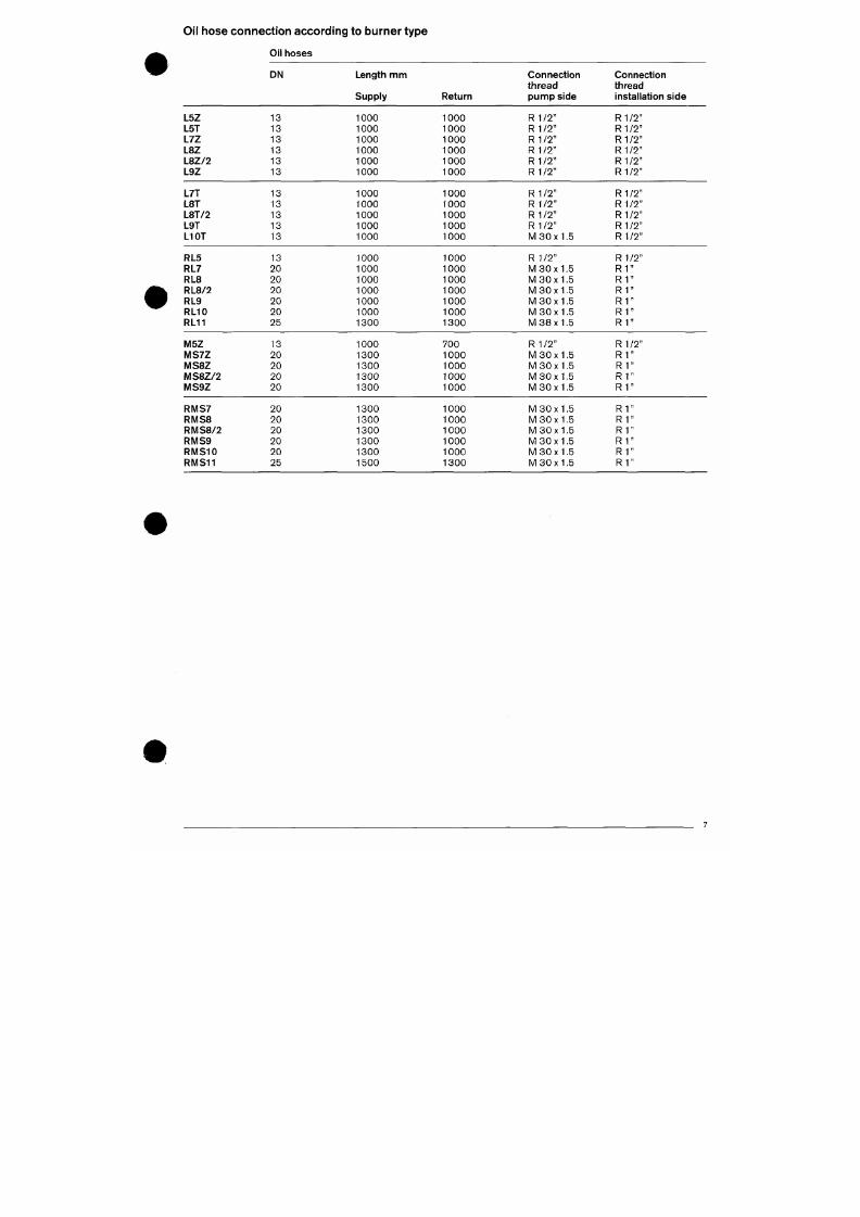
7/18/2019 M14 Thermal Fluid
http://slidepdf.com/reader/full/m14-thermal-fluid 360/486
air/gas separator should be installed as close to the burner
as possible (see technical worksheets). This is part icularly
impo rtant on residual fuel oil installat ions. The air/gas
separator must be installed in the correct direct ion, as
switch).
Shut-off combination befo re the burner
The ball cock is normally only closed during lengthy service
Oil hose connection a ccording to burner type
Oil hoses
DN
Length nnm
Supply Return
Connection
thread
punnpside
Connection
thread
installation side
L5Z
L5T
L7Z
L8Z
L 8Z / 2
L9Z
L7T
L8T
L8T/2
L9T
L10T
RL5
RL7
RL8
RL8/2
RL9
RL10
RL11
13
13
13
13
13
13
13
13
13
13
13
13
20
20
20
20
20
25
1000
1000
1000
1000
1000
1000
1000
1000
1000
1000
1000
1000
R 11T
R1 /2 "
R 11T
R 11T
R1 /2 "
R1 /2 "
R1/2"
R1 /2 "
R1 /2 "
R1/2"
R1 /2 "
R1 /2 "
1000
1000
1000
1000
1000
1000
1000
1000
1000
1000
R 1
1T
R1 /2 "
R1 /2 "
R1 /2 "
M 30x1 .5
R1/2"
R1 /2 "
R1 /2 "
R1 /2 "
R1 /2 "
1000
1000
1000
1000
1000
1000
1300
1000
1000
1000
1000
1000
1000
1300
R1 /2 "
M 3 0 x 1 . 5
M 30x1 .5
M 3 0 x 1 . 5
M 3 0 x 1 . 5
M 30x1 .5
M 38x1 .5
R 11 T
R 1 "
R 1
R1
R1
R 1
R 1
M 5 Z
MS7Z
IVIS8Z
13
20
20
1000
1300
1300
700
1 0 0 0
1000
R 11T
M 3 0 x 1 . 5
M 3 0 x 1 . 5
R 1 / 2 "
R 1 "
R 1 "
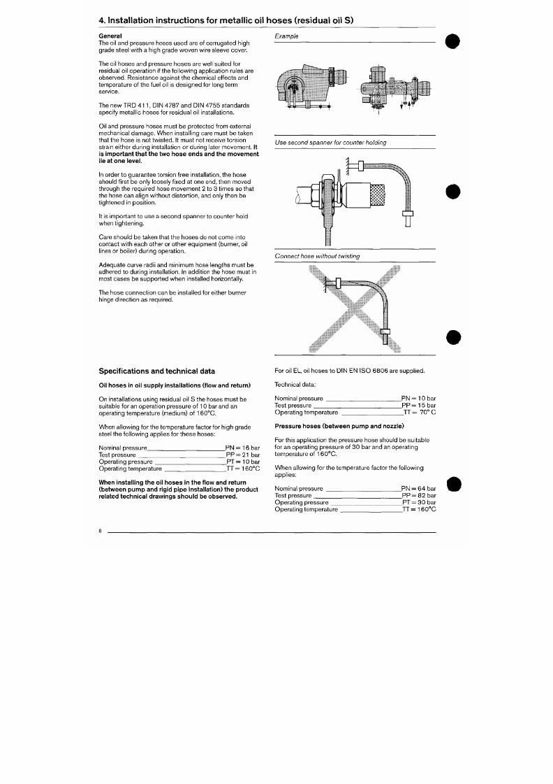
7/18/2019 M14 Thermal Fluid
http://slidepdf.com/reader/full/m14-thermal-fluid 361/486
M S 8 Z / 2
MS9Z
RIVIS7
20
20
20
1 3 0 0
1300
1300
1 0 0 0
1 0 0 0
1 0 0 0
M 3 0 x 1 . 5
M 3 0 x 1 . 5
M 3 0 x 1 . 5
R 1 "
R 1 "
R 1 "
4. Ins ta l la t ion ins t ruc t ions for me ta l l i c o il hos es ( res idua l o i l S)
General
The oil and pressure hoses used are of corrugated high
grade steel with a high grade woven wire sleeve cover.
The oil hoses and pressure hoses are well suited for
residual oil operat ion if the following applicat ion rules are
observed.
Resistance against the chemical ef fects and
temperature of the fuel oil is designed for long term
service.
The new TR D 4 1 1 , D IN 4787 and DIN 4755 s tandards
specify me tall ic hose s for residual oil installat ions.
Oil and pressure hoses must be protected from external
mechanical damage . Wh en instal l ing care must be taken
that the ho se is not twiste d. It must not receive tors ion
strain either during installat ion o r during later moveme nt. It
is important that the two hos e ends and the mo vem ent
lie at one level.
In order to gua rantee tors ion free installation, the hose
should f irst be only loosely f ixed at one end, then move d
through the required hose m oveme nt 2 to 3 t imes so that
the hose can align without distort ion, and only then be
t ightened in posi t ion.
It is important to use a second spanner to counter hold
when t ightening.
Care should be taken that the ho ses do not come into
Example
Use second spanner for counter holding
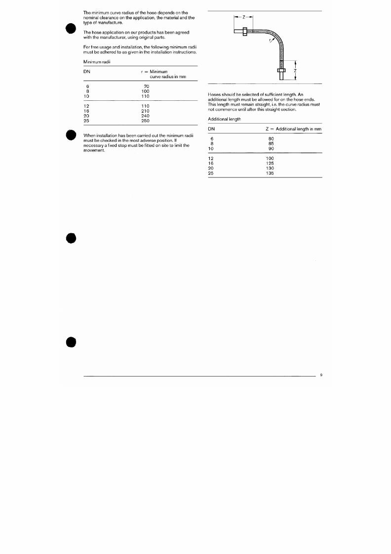
7/18/2019 M14 Thermal Fluid
http://slidepdf.com/reader/full/m14-thermal-fluid 362/486
contact with each other or other equipment (burner, oil
l ines or boiler) during operat ion.
Adequ ate curve radi i and minimum hose lengths must be
Conne ct hose without twisting
The minimum curve radius of the ho se depen ds on the
nominal clearance on the applicat ion, the material and the
type of manufacture.
The hose appl icat ion on our products has been agree d
with the manufacturer, using original parts.
For free usage and installat ion, the following minimum radii
must be adhered to as given in the installat ion instruct ions.
Minimum radii
DN r = Minimum
curve radius in mm
6
8
10
70
100
110
12
16
20
25
110
210
240
250
Hose s sho uld be selected of suff icient leng th. An
addit ional length must be al lowed for on the hose ends .
This len gth m ust remain straight, i.e. the curv e radius m ust
not commence unti l after this straight sect ion.
Addit ional length
#
When installat ion has been carried out the minimum radii
must be checked in the most adverse posit ion. I f
necessa ry a f ixed stop must be f it ted on site to l imit the
movement .
DN Z = Addit iona l length in mm
6
8
10
12
16
20
80
85
90
100
125
130
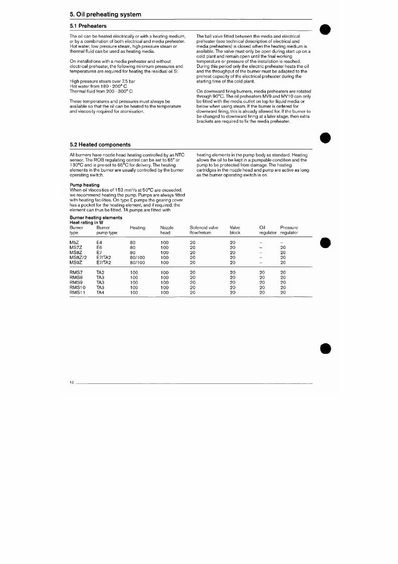
7/18/2019 M14 Thermal Fluid
http://slidepdf.com/reader/full/m14-thermal-fluid 363/486
25 135
5. Oil preheating system
5.1 Preheaters
Th e
oil can
be heated electr ically
or
wi th a heating m edium,
or
by
a combinat ion of both electr ical and media preheater.
Hot water ,
low
pressure steam, high pressure steam
or
thermal f luid can be used
as
heating media.
On installat ions with
a
med ia preheater and without
electr ical preheater, the fo l lowing m inimum pressures and
tempe ratures are required for heating the residual oil S :
High pressure steam over 7.5 bar
Hot water f rom 180 - 2 0 0 ° C
Thermal f luid from
200
-
3 0 0 °
C
These temperatures and pressures must always be
available
so
that the
oil can be
heated to
the
temperature
and v iscosi ty required
for
a tomisat ion.
The ball valve f it ted betw een
the
media and e lectr ical
preheater (see technical descript ion of electr ical
and
media preheaters)
is
closed wh en
the
heating m edium
is
available. The valve must o nly be open during start up on
a
cold plant and remain open unti l the f inal working
temperature or pressure of the installation is reached.
During this period only the electr ic preheater heats the oil
an d the t h roughput of the b urner must be adapted to the
preheat capaci ty of the electr ical preheater during
the
start ing t ime of
the
cold plant.
On d ow nwa rd f i ring burners, media preheaters
are
rotated
through 90 °C. The
oil
p reheaters M V9 and MV 10
can
only
be f it ted w ith
the
media out let
on top for
liquid m edia or
below when using steam. If
the
burner
is
o rdered
for
dow nwa rd f i r ing, th is is already allowed for. If the burner
to
be changed to downward f i ring at a later sta ge, then extra
brackets are required to fix the media preheater.
5.2 Heated components
#
All burners have nozzle head heating controlled by an NTC
sensor.
The ROB
regulat ing control can
be set
to
65°
or
130°C and is pre-set to 65 °C
for
delivery. The heating
elements
in the
burner are usually con trolled
by
the burner
operat ing switch.
heat ing elem ents in the pum p bod y as standard . Heat ing
allows
the oil
to
be
kept
in
a pumpable condit ion and
the
pump
to be
protec ted f rom dam age. The heat ing
cartr idges
in the
nozzle h ead
and
pump
are
act ive
as
long
as the burner operat ing sw itch is on.
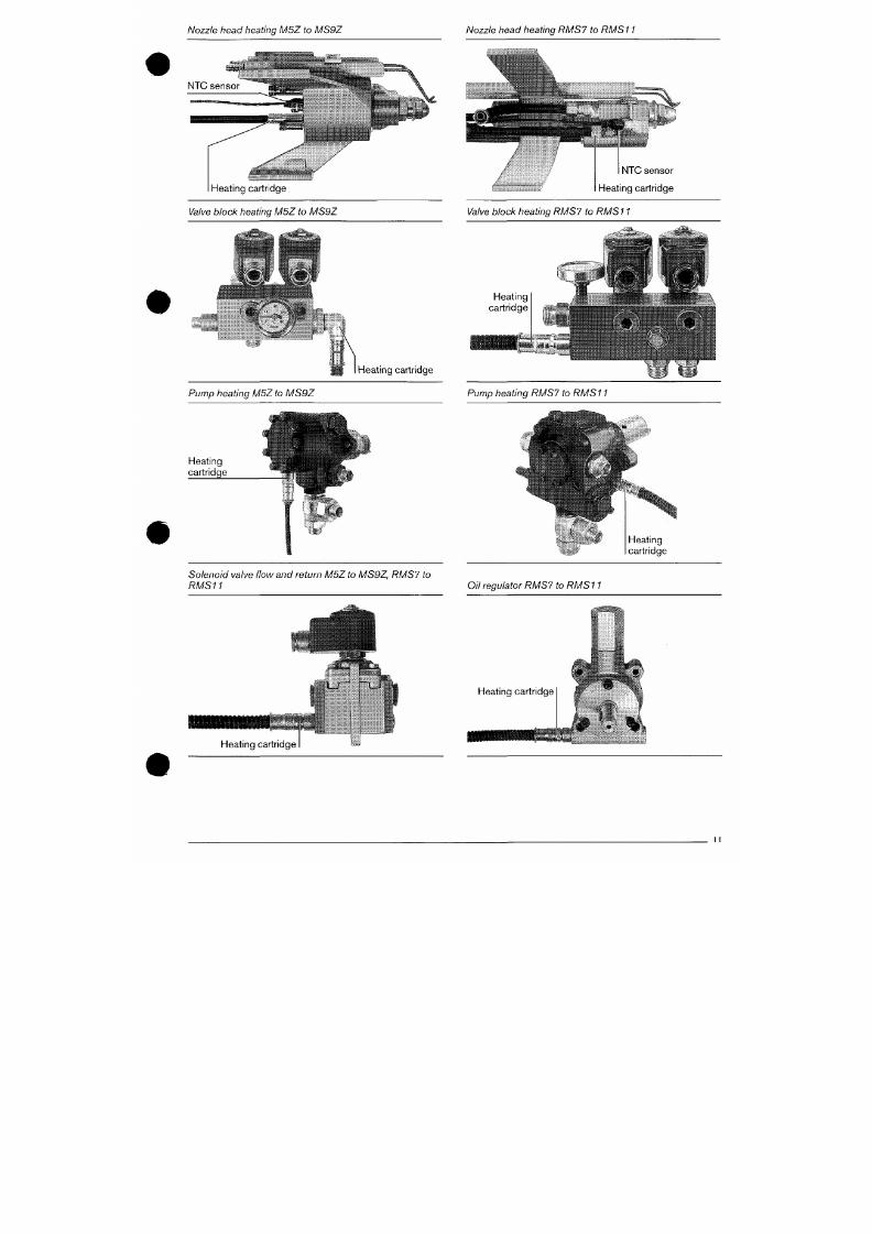
7/18/2019 M14 Thermal Fluid
http://slidepdf.com/reader/full/m14-thermal-fluid 364/486
Pump heat ing
When
oil
viscosit ies
of
152
mmVs
at
50 °C
are
exceeded,
Nozzle head heating M5Z to MS9 Z Nozzle head heating RMS 7 to RMS 11
i-;,,- I
NTC sensor
Heating cartridge
Valve block heating M5Z to MS9Z
äiw*
NTC sensor
Heating cartridge
Valve block heating RMS7 to RMS 11
Heat ing
cart r idge
tm,.
« u l t - . •
ilé-l
K m
I Heating cartridge
7/18/2019 M14 Thermal Fluid
http://slidepdf.com/reader/full/m14-thermal-fluid 365/486
Pump heating M5Z to MS9Z Pump heating RMS7 to RMS11
6. Oi l p um ps
The pumps are supplied suitable for connection in a two
pipe oil system.
Pumps are supplied with pressure regulating and shut off
valves. The pressure regulating valves keep the p ress ure
constant .
Adjustment
• The oil l ine on the suction side must be primed and the
pum p vented pr ior to comm issioning, otherwise the
pump will be damaged due to running dry.
• Insert gauge to chec k the vacuum or supply or ring
main pressure on the suction side of the pump.
• A pressure gaug e must be conn ected in to tappin g (5)
to measure the pump pressure.
• To adjust the oil pressure, remove cap nut (4) and se t
the required pressure.
Cloc kwis e rotation = pressure increase
Ant ic lockw ise rotat ion = pressure decrease
The suction resistance should not exceed 0.4 bar.
Max. supply pressure on pump type J
on pumps typ es E and TA
(measured at the pump).
Maximum oil supply temperature
on pumps typ e E and TA
. 2.0 bar
5.0 bar
90°C
The pum p fi lter will require cleaning from tim e to t ime,
depend ing on the degree of
fouling.
With a high degree of
foul ing,
the vacuum on the su ction side increas es. To
remove the f i lter for cleanin g, extract the eight scre ws (1 2)
on the pump cover.
After replacing the filter
erasure
that the pump cover is
tightly sealed.
Single pipe operation
In some instances when operating with oil EL,
J
and TA
pump s can be used with one p ipe systems.
The fo l lowing should be noted :
As there is no suctio n lif t by the pump in a single pipe
system,
the oil supply m ust have a guaran teed posit ive
head at the pum p inlet.
The bypass plug in the pump should be removed and the
pump return connect ion p lugged.
The supply l ine should always be vented when
commissioning.
As it is not possib le to vent via the pum p return on s ingle
pipe installat ions, the supp ly l ine must in this instance be
fu lly vented when comm issioning.
P ump coupling
A flexible coupling is f it ted between fan rotor and pump.

7/18/2019 M14 Thermal Fluid
http://slidepdf.com/reader/full/m14-thermal-fluid 366/486
Filter for J and E pumps
When adjusting the intermediate coupling ensure that
#
Pump coupling
Pump J6 + J7
8
Pump E4, E6, E7
Q
.sP
10 11
t
2a 3 12
Pump TA2, TA3, TA4
7 4 6 2 5 2a 3
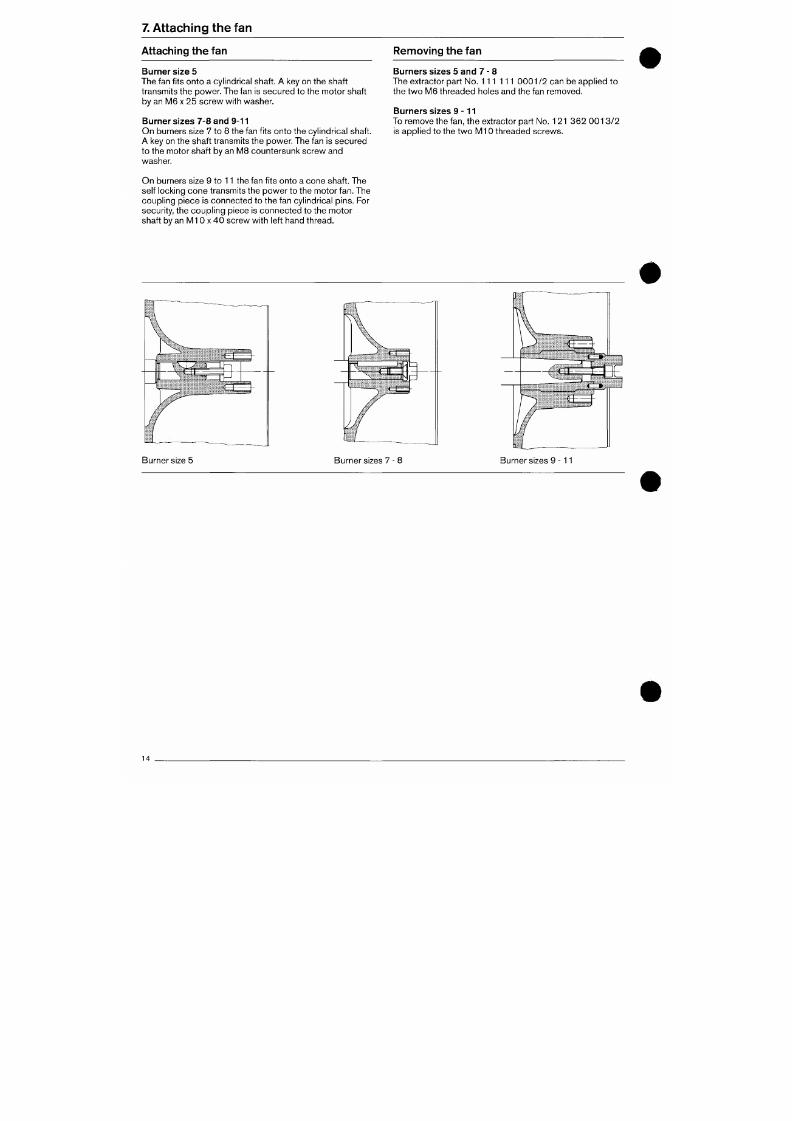
7/18/2019 M14 Thermal Fluid
http://slidepdf.com/reader/full/m14-thermal-fluid 367/486
Legend
1 Suct ion connect ion 7 Locking scre w
7. Attaching the fan
Attaching the fan Rennoving the fan
Burner size 5
The fan f its onto a cylindrical shaft. A key on the s haft
transmits the power. The fan is secured to the motor shaft
by an M6 x 25 screw with washer.
Burner sizes 7-8 and 9-11
O n b urners size 7 to 8 the fan fits onto the cylindrica l shaft.
A key on the shaft transmits the po wer. The fan is sec ure d
to the motor shaft by an MB countersunk screw and
washer.
Burners sizes 5 and 7 - 8
The ext ractor part No. 111 111 0001/2 can be appl ied to
the two
MB
threaded holes and the fan removed.
Burners sizes 9
-
1 1
To remove the fan, the ext ractor part No. 121 3 62 0 0 1 3 /2
is appl ied to the two M l 0 threaded screw s.
O n b urners size 9 to 11 the fan fits onto a cone sh aft. The
self locking cone t ransmits the pow er to the motor fan. The
coupling piece is connected to the fan cylindrical pins. For
secur i ty , the coup l ing piece is connecte d to the m otor
shaf t by an M l 0 X 40 screw with lef t hand thread.
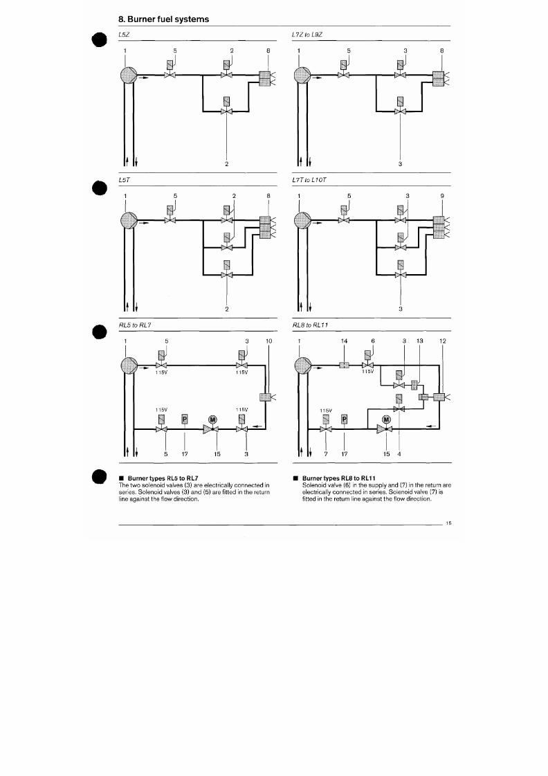
7/18/2019 M14 Thermal Fluid
http://slidepdf.com/reader/full/m14-thermal-fluid 368/486
8. Burner fue l sy s tem s
L5Z L7ZtoL9Z
I .
t I
L5T
O
<
<
<
<
<
X
t *
L7TtoL10T
A
<
<
<
<
<
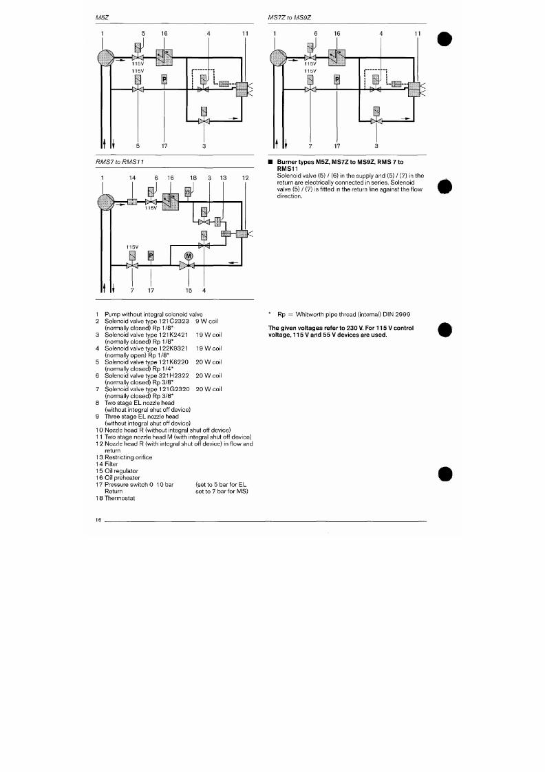
7/18/2019 M14 Thermal Fluid
http://slidepdf.com/reader/full/m14-thermal-fluid 369/486
M5Z MS7Z to MS9Z
5 16
11
t i
115V ^
115V
i B
^ —
J
Ä
• { H -
n
I — \ ^
<
<
11
5 17
t I
t > > < i -
J
-ce-
— E ^
<
<
17
RMS7 to RMS11
^
1 14 6 16 18 3 13
12
Z ,
115V
K J t i"' ' t
Burner types M5 Z, MS7Z to MS 9Z, RM S 7 to
RMS11
Sole noid valve (5) / (6) in the supply and (5) / (7) in the
return are electr ically connected in series. Solenoid
valve (5) / (7) is fitted in the return line against the flow
direct ion.
<
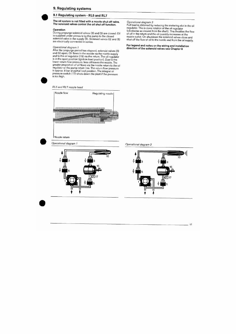
7/18/2019 M14 Thermal Fluid
http://slidepdf.com/reader/full/m14-thermal-fluid 370/486
1 1 5 V
- 0 ^
9. Regu la ting sys tem s
9.1 R egulating system - RL5 and RL7
The oil system is not fitted with a n ozzle shu t off valve.
Th e solenoid va lves control th e oil shut off function .
Operat ion
During prepurge solenoid valves (3) and (5) are closed. Oil
is supplied under pressure by the pump to the closed
solenoid valve in the supply (5). Soleno id valves (3) and (5)
are electr ically connected in series.
Operational diagram 1
After the prepurge period has elapsed, solenoid valves (3)
and (5) ope n. Oil f lows to the nozzle via the nozzle supply
and to the o il regulator (15) via the return. The oil regulator
is in the ope n po sition ( ignition load po sition). Due to the
lower return flow pressure, less oi l leaves the nozzle. The
greater p roportio n of oi l f lows via the nozzle return to the oil
regulator or the pum p return l ine. The return flow pressure
is approx. 8 bar at partial load position. The integral oil
pressure switch (17) shuts down the plant i f the pressure
is too high.
Operational diagram 2
Full load is obtaine d by reducing th e m etering slot in the oil
regulator. This is don e rotation of the oil regulator
(clockwise as viewed from the shaft) . This thrott les the f low
of oi l in the return an d the oil quantity increases at the
nozzle outlet. On shutdown the solenoid valves close and
shut off the flow of oi l to the nozzle and from the oil supply.
For legend and notes on the wiring and installation
direction of the solenoid valves see Chapter 8
RL5 and RL7 nozzle head
Nozzle flow
Regulating nozzle
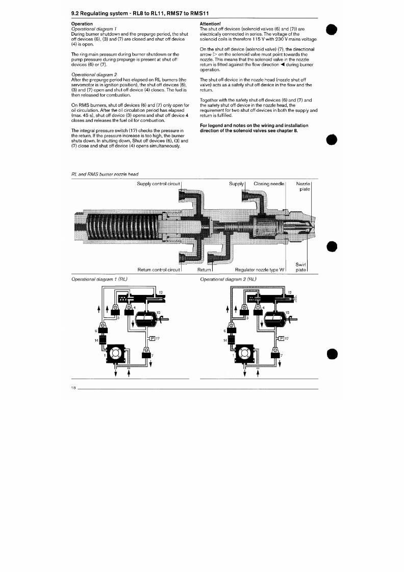
7/18/2019 M14 Thermal Fluid
http://slidepdf.com/reader/full/m14-thermal-fluid 371/486
9.2 R eg ula t ing systenn - RLS to RL11 , RM S7 to RM S1 1
Operation
Operational diagram 1
During burner shutdown and the prepurge period, the shut
off devices (6), (3) and (7) are clos ed and shut off device
(4) is ope n.
The ring main pressure during burner shutdown or the
pump pressure during prepurge is present at shut off
devices (6) or (7).
Operational diagram 2
After the prepurge period has elapsed on RL burners (the
servom otor is in ignition posit ion), the shut off devic es (6),
(3) and (7) open and shut off device (4) closes. The fuel is
then released for combustion.
On RMS burners, shut off devices (6) and (7) only open for
oil circula tion. After the oil circulation period has elapsed
(max. 45 s), shut off device (3) opens and shut off device 4
closes and releases the fuel oil for co mb ustion .
The integral pressure switch (17) checks the pressure in
the return. If the pressure increase is too h igh, the burner
shuts down. In shutt ing down, Shut off devices (6), (3) and
(7) close a nd shut off device (4) ope ns simultaneously.
Attention
The shut off devices (solenoid valves (6) and (7)) are
electrically con nec ted in series. The voltage of the
solenoid coi ls is therefore 11 5V with 23 0 V mains voltage
On th e shut off device (solenoid valve) (7), the dire ctional
arrow > on the solen oid valve must point towa rds the
nozzle. This means that the solenoid valve in the nozzle
return is f it ted against the f low direction -4 during bu rner
operat ion.
The shut off device in the nozzle head (nozzle shut off
valve) acts as a safety shut off device in the f low and the
return.
Together with the safety shut off devices (6) and (7) an d
the safety shut off device in the nozzle head, the
requirement for two shut off devices in both the supply and
return is fulfilled.
For legend and notes on the wiring and installation
direction of the s olenoid valves se e chapter 8.
RL and RMS burner nozzle head
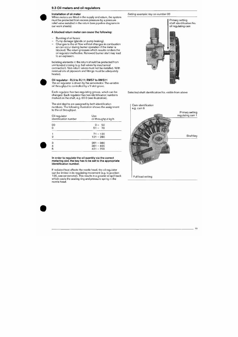
7/18/2019 M14 Thermal Fluid
http://slidepdf.com/reader/full/m14-thermal-fluid 372/486
Supply control circuit
9.3 Oil meters and oil regulators
Installation of oil meter
W he n m eters are f it ted in the supply and return, the system
must be protected from excess pressure by a pressure
relief valve installed in the return (see pipeline diagrams in
our work sheets).
A blocked return meter can cause the fol lowing:
- Burs ting of oil hoses
- Pum p damage (glands on pump leaking).
- Cha nges to the oil f low without cha nges in com bustio n
air can occur du ring burner operation if the meter is
blocked.
The return pressure wh ich results renders the
oil regulator ineffective. Renewed burner start may lead
to an explosion.
Setting exam ple: key on number 00
Primary sett ing
shaft identif ication No.
oil regulating cam
Isolating elements in the return should be protected from
uninten ded closing (e.g. ball valves by m echanical
connection). Non-return valves must not be installed. With
residual oils all pipew ork and f itt ings m ust be adequately
heated.
Oil regulator - RL5 to RL11; RMS7 to RMS11
The oil regulator is driven by the servomotor. The variable
oil throu ghp ut is controlled by a V-slot gro ve.
Each regulator has two regulating groves, which can be
changed .
Each regulator has two identif ication numbers
mark ed on the shaft, e.g. 00 -0 (see il lustration).
The slot depths are assigned by both identif ication
numbers. The following il lustration shows the assignment
Selected shaft identif ication No. visible from above
Cam identif ication
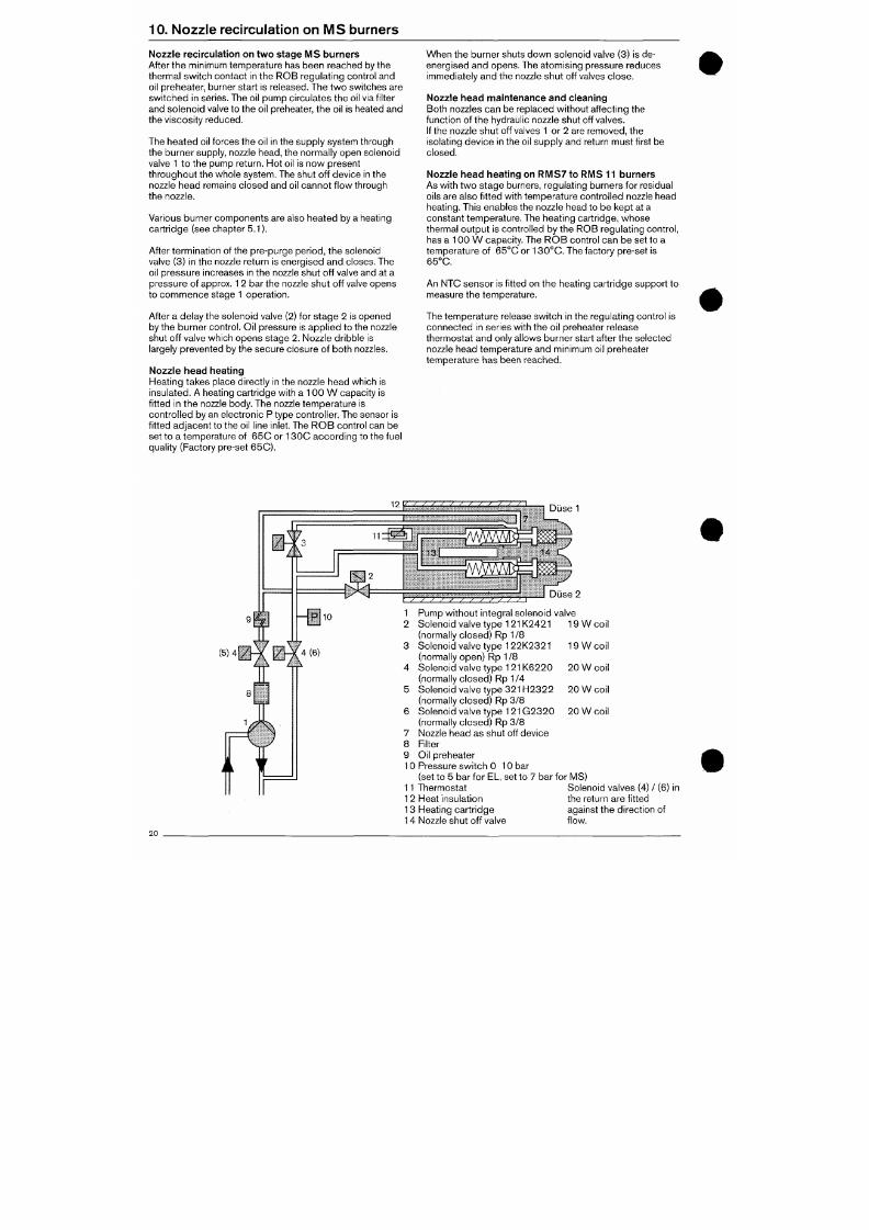
7/18/2019 M14 Thermal Fluid
http://slidepdf.com/reader/full/m14-thermal-fluid 373/486
to the oil throughput.
e.g. cam 6
Primary setting
10. Nozz le rec ircu la t ion on M S burners
Noz zle recirculation on two stage M S burners
After the minimum temperature has been reached by the
thermal switch contact in the ROB regulating control and
oil preheater, burner start is released. The tw o s witches are
sw itch ed in series. The oil pum p circ ulates the oil via fi lter
and solenoid valve to the oil preheater, the oil is heated and
the viscosity reduced.
The heate d oil forces the oil in the supply system through
the burne r supply, nozzle head, the normally open solenoid
valve 1 to the pum p return. Hot oil is now present
throu gho ut the whole sy stem. The shut off device in the
nozzle head remains closed and oil cannot f low through
the nozzle.
Various burner components are also heated by a heating
cartridge (see chapter 5.1).
After termination of the pre-purge period, the solenoid
valve (3) in the nozzle return is energised and closes. The
oil pressure increases in the nozzle shut off valve and at a
pressu re of approx. 1 2 bar the nozzle shut off valve opens
to commence s tage
1
operation.
After a delay the solenoid valve (2) for sta ge 2 is opened
by the b urner co ntrol. Oil pressure is applie d to the nozzle
shut off valve which o pens stage 2. Nozzle dribble is
largely prev ented by the secure closure of both nozzles.
Nozzle head heating
Hea ting takes place directly in the nozzle head which is
insulated.
A heating cartridge with a 100 W capacity is
When the burner shuts down solenoid valve (3) is de-
energised and opens. The atomising pressure reduces
immediately a nd the nozzle shut off valves clo se.
Nozzle head maintenance and cleaning
Both nozzles can be replaced without affecting the
function of the hydraulic nozzle shut off valves.
If the no zzle sh ut off valves 1 or 2 are remov ed, the
isolating device in the oil supply and return must first be
closed.
Nozzle head heating on RMS7 to RMS 11 burners
As with two stage burners, regulating burners for residual
oils are also f it ted with temperatu re con trolled nozzle head
heating.
This enables the nozzle head to b e ke pt at a
constant temperature. The heat ing cart r idge, whose
thermal output is controlled by the ROB regulating control,
has a 100 W capacity. The RO B co ntrol can be set to a
tempe rature of 65 °C or 13 0°C. The factory pre-set is
65°C.
An NTO sensor is f it ted on the heating cartridge support to
measure the temperature.
The tem pera ture release sw itch in the regulating control is
con nec ted in series with the oil preheater release
thermostat and only allows burner start after the selected
nozzle head temperature an d minimum oil preheater
temperature has been reached.
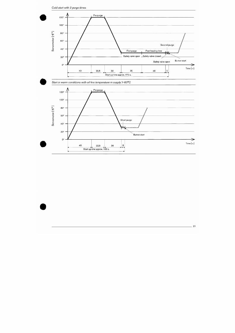
7/18/2019 M14 Thermal Fluid
http://slidepdf.com/reader/full/m14-thermal-fluid 374/486
fitted in the nozzle body. The nozzle temperature is
Cold start with
2
purge times
O
•*->
O
E
o
>
0)
120°
100°
80°
60°
40°
20°
Pre-purge
Second pu rge
First purge
Post heat ing t ime
Safety va lve open -S af ety va lve c losed
Safety va lve ope n
Burner start
3 5
4 0
Start up t ime approx. 175 s.
>
Time [ s ]
Start in warm conditions with oil line temperature in supply > 60°C
120°
100°
7/18/2019 M14 Thermal Fluid
http://slidepdf.com/reader/full/m14-thermal-fluid 375/486
V-
80°
Addit ional start circuit with two purge t imes for RM S7
to RIVIS11 burners, DIN 4787
Operat ion
After prepu rge has taken place and the ignit ion posit ion
has been reach ed, the safety valves are opened for 3 5 s to
enable the burner fuel system components to be heated.
The safety solen oid valves are then close d for approx. 40
s. In the meantime the oil preheater will regain heat and
can give the maximum tempe rature after the 40 s have
elapsed.
After this period the safety solenoid valves are re-ope ned
and at the same tim e a return signal is given to the burner
contro l to continue the start up seque nce. An interval,
determined by the burner controller, of about 6 s produces
a secon d purge t im e up to the oil release where the
temperature peak of the oil preheater is uti l ised for the
moment of ignit ion.
So that the cold start process does not take place when
start ing from warm co ndit ions or after a short shut d ow n
per iod,
a therm ostat f it ted in the bu rner fuel line system
between oil preheater outlet and distribution piece
determines w hether it is a cold sta rt or a warm start w ith
short purge period. The thermostat switching point is
approx. 55 - 60 °C. If the oil l ine temperature is more than
this f igure before the boiler regulator s witches on , then
only the short purg e t ime of 6 s is used for the sub sequ ent
burner start. This m onitoring ass ures that there will be no
unnecessary delays during the start process.
i i i . :
s m :
X
=
, - i . .* .* .
/ ; » , . . . * . . .
{
: ,* .
" :
: : i ^ ; • •
«M4vt * : ^ "*"
•• .^t »*> fc'irl"**'" *
-' • ihi'.:...:
• • : : ; ? . . .
' ' • ' • - * ' : j . •
• - •
T
r^
' • • - f . / ' . . : •
. . 4 » V . « » * • • ' •
K • ; • • * •
' , • * « . • V * * * * * . *
-..rrr--
> . , .^
• > • * » * • -
The circuit is design ed in such as way tha t there is a ballast
effect as far as the sw itching cond it ion of the thermostat is
conce rned .
This m eans that once start up has begun, any
thermostat response will not produce an alteration in the
seq uen ce of operations, so that either a cold or a warm
start always clearly takes place .
If the oil tempe rature s t ipulates a warm s tart, the start up
time of the burner is shortene d by 45 s, the t ime usually
used as the delay period.
The circulation return is always f it ted into the pump return.
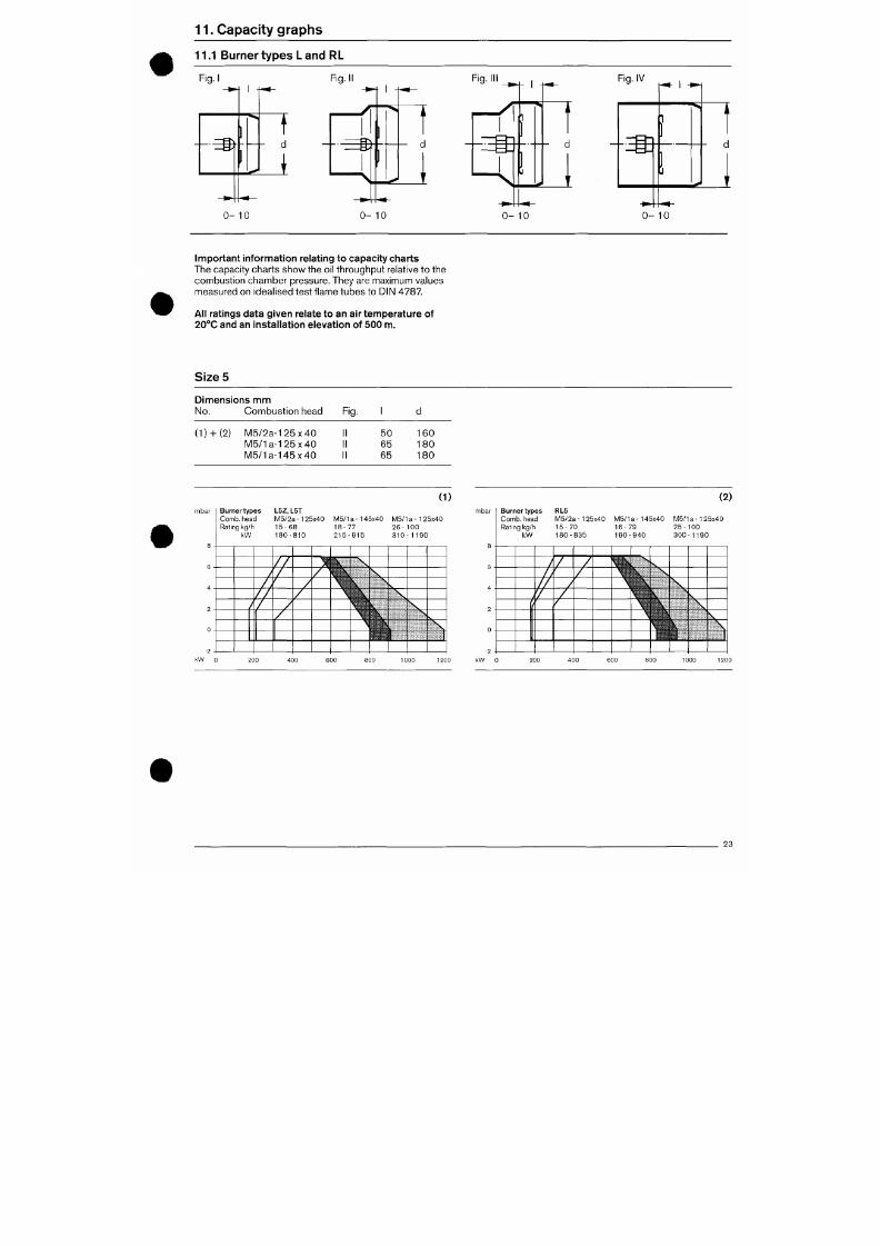
7/18/2019 M14 Thermal Fluid
http://slidepdf.com/reader/full/m14-thermal-fluid 376/486
Nozz le heads are tested safety devices and according
11. Capac i ty g raphs
11.1 Burner typ es
L
and RL
Fig. I
-m
0 - 1 0
Fig. II
^ '
^ 1
1 , ^
" t
a
-J '^
0 - 1 0
Fig. Ill
Fig. IV
m
0 - 1 0
0 - 1 0
Impo rtant infornnation relating to capacity charts
The capacity charts s how the oil through put relative to the
combustion chamber pressure. They are maximum values
measured on idealised test f lame tubes to DIN 478 7.
All ratings data given relate to an air temperature of
20°C and an installation elevation of 500 m.
Sizes
Dimensions mm
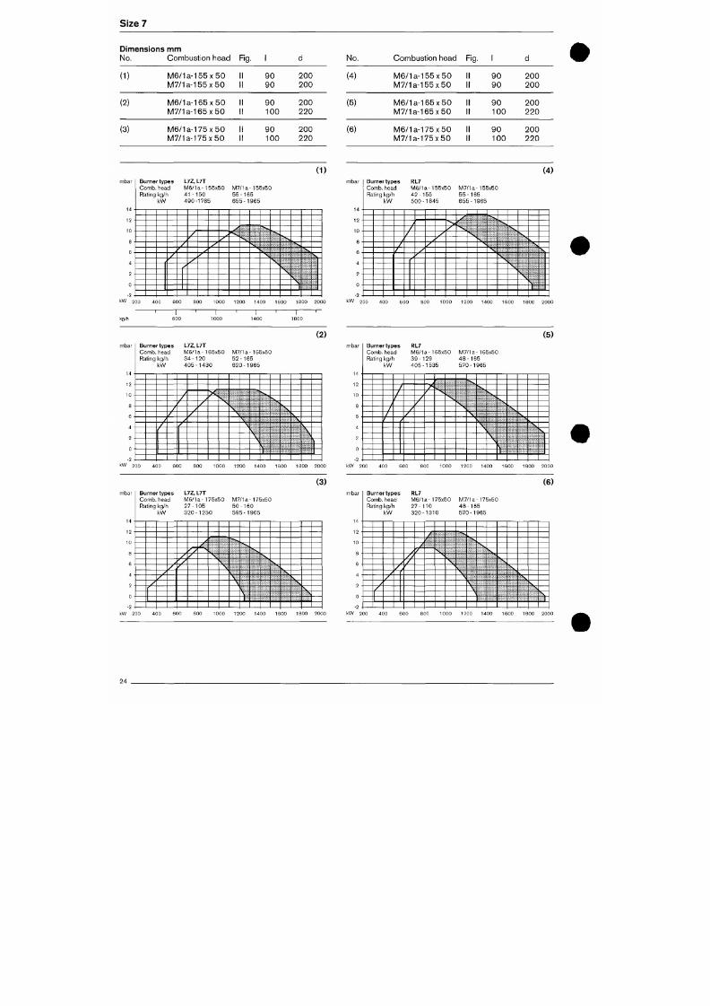
7/18/2019 M14 Thermal Fluid
http://slidepdf.com/reader/full/m14-thermal-fluid 377/486
No. Combust ion head
Fig.
1
d
Size
7
Dimensions
mm
No. Combustion head
Fig.
(1)
(2)
(3)
M6/1a-155x50
1
M7/1a-155x50
1
M6/1a-165x50
1
M7/1a-165x50
1
M6/1a-175x50 1
M7/1a-175x50 1
1 90
1 90
1 90
1 100
1 90
1 100
200
2Ö0
200
220
200
220
(1)
mbar
- 2
•
Burner types
C o m b ,
head
Rating kg/h
k W
L7Z,L7T
M 6 / 1 a - 1 55x50
4 1 - 1 5 0
490-1785
M7/1a-155x50
55-165
655-1965
V
No.
(4)
(5)
(6)
Combustion head
M6/1a-155x50
M7/1a-155x50
M6/1a-165x50
M7/1a-165x50
M6/1a-175x50
M7/1a-175x50
Fig. 1
9 0
9 0
9 0
100
9 0
100
d
200
2 0 0
200
2 2 0
200
220
(4)
mbar
^
- 2
•
Burner types
C o m b ,
head
Rating kg /h
k W
i
/
/
RL7
M6/1a-155x50
42-155
500-1845
y
/
M7/1a-155x5C
55-165
655-1965
kW 200
600 800 1000 1200 1400 1600 1800 2000
k W 200 400
1000 1200 1400 1600 1800 2000
kg/h 600 1800
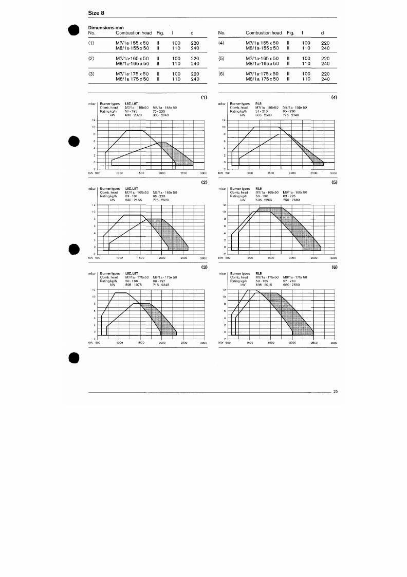
7/18/2019 M14 Thermal Fluid
http://slidepdf.com/reader/full/m14-thermal-fluid 378/486
(2)
(5)
Sizes
Dimensions mm
No. Com bustion head Fig.
(1)
(2)
(3)
M 7 / 1 a - 1 5 5 x 5 0 1
M 8 / 1 a - 1 5 5 x 5 0 1
M 7 / 1 a - 1 6 5 x 5 0 1
M 8 / 1 a - 1 6 5 x 5 0 1
M 7 / 1 a - 1 7 5 x 5 0 1
M 8 / 1 a - 1 7 5 x 5 0 1
1 100
1 110
1 100
i 110
1 100
1 110
220
240
220
240
220
240
(1)
mbar
-2 •
Burner types L8Z, L8T
Comb, head M7/1 a - 1 55x50
Rating kg/h 57 -1 95
kW 680 - 2320
M 8 / 1 a - 1 5 5 x 5 0
70 - 230
835 - 2740
No.
(4)
(5)
(6)
Com bust ion head 1
M 7 / 1 a - 1 5 5 x 5 0 1
M B / l a - l 5 5 x 5 0 1
M 7 / 1 a - 1 6 5 x 5 0 1
iV IS /la - l 6 5 x 5 0 1
M 7 / 1 a - 1 7 5 x 5 0 1
M 8 / 1 a - 1 7 5 x 5 0 1
-ig-
1
1 100
1 110
1 100
1 110
1 100
1 110
d
220
240
220
240
220
240
(4)
mbar
10
8
-2
Burner types RL8
Comb, head M7 /1a-155x 50
Rating kg/h 51 -2 10
kW 605 - 2500
>
M8/1a -155x50
6 5 - 2 3 0
775-2740
^ 5 ^
(2) (5)
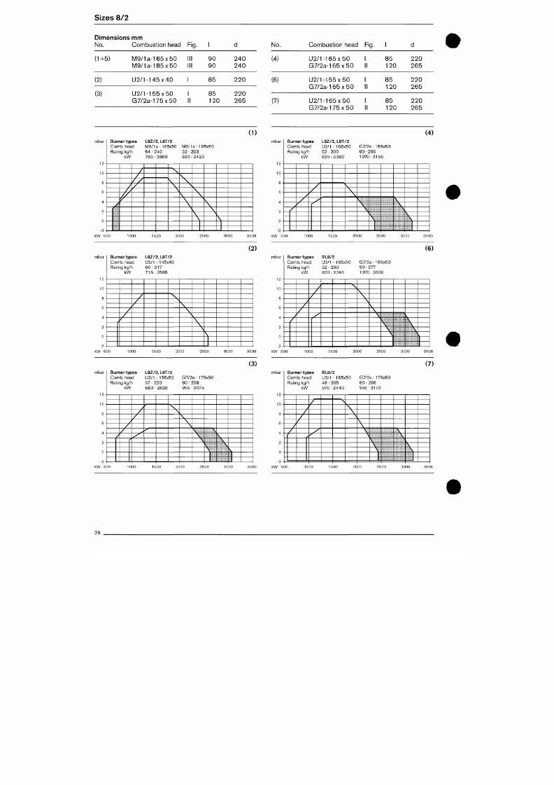
7/18/2019 M14 Thermal Fluid
http://slidepdf.com/reader/full/m14-thermal-fluid 379/486
mbar
Burner types L8Z, L8T
Comb, head M7/1 a • 165x50 M 8 / 1 a - 1 6 5 x 5 0
mbar
Burner types RL8
Comb, head M7 /1a-165 x50 M 8 / 1 a - 1 6 5 x 5 0
Sizes 8/2
Dimensions mm
No.
(1+5)
(2)
(3)
Combust ion head
M 9 / 1 a - 1 6 5 x 5 0
IV IQ / la - l 8 5 x5 0
U 2 / 1 - 1 4 5 x 4 0
U 2 / 1 - 1 5 5 x 5 0
G 7 / 2 a - 1 7 5 x 5 0
Fig.
Ill
III
II
1
9 0
9 0
8 5
85
120
d
2 4 0
2 4 0
2 2 0
2 2 0
265
(1)
mbar
i n
-2 -
Burner types
Comb, head
Rating kg/h
kW
L8Z/2,
L8T/2
M9/1a -165x50
64 - 240
7 6 0 - 2 8 6 0
M9/1a -185x50
52 - 203
6 2 0 - 2 4 2 0
\
KW 500
(2)
No.
(4)
(6)
(7)
Combust ion head
U 2 / 1 - 1 6 5 x 5 0
G 7 / 2 a - 1 6 5 x 5 0
U 2 / 1 - 1 5 5 x 5 0
G 7 / 2 a - 1 6 5 x 5 0
U 2 / 1 - 1 6 5 x 5 0
G 7 / 2 a - 1 7 5 x 5 0
Fig.
1
8 5
1 120
8 5
1 120
8 5
1 120
d
2 2 0
265
2 2 0
265
220
265
(4)
mbar
- 2 •
Burner types
Comb, head
Rating kg/h
kW
L8Z/2,
L8T/2
U2/1 -165 x50
52 - 200
6 2 0 - 2 3 8 0
^-
f^
S,
s .
s
G7/2a-165x50
9 0 - 2 6 5
1070-3155
V
\
\
^
V
V
\ ,
N,
S
S,
S,
(6)
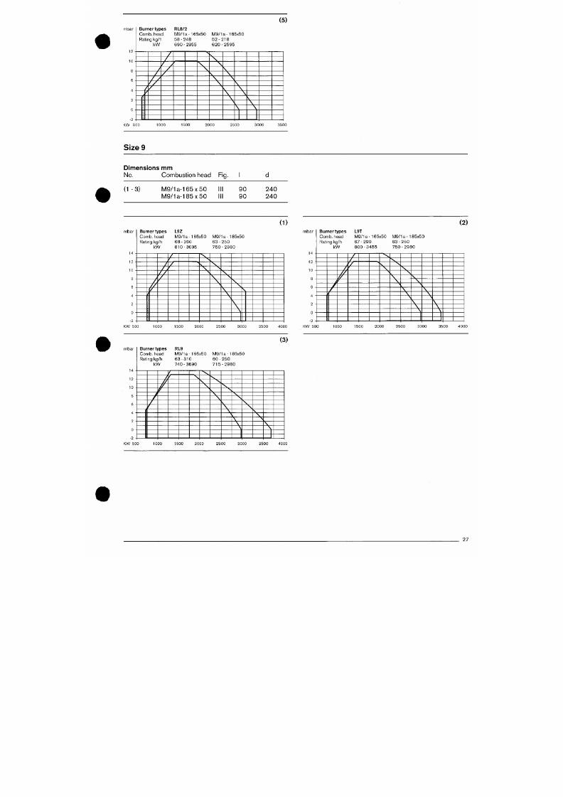
7/18/2019 M14 Thermal Fluid
http://slidepdf.com/reader/full/m14-thermal-fluid 380/486
mbar
Burner types
Comb, head
L8Z/2, L8T/2
U2/1 -145x40
mbar
Burner types
Comb, head
RL8/2
U2/1 -155x50 G7/2a -165x50
(5)
mbar
-2 -
Burner types
C o m b , head
Rating
kg /h
k W
/
RL8/2
M9/1a-165x50
58-248
690-2955
M9/1a-185x50
5 2 - 2 1 8
6 2 0 - 2 5 9 5
Size 9
Dimensions m m
No. Combustion head Fig.
( 1 - 3 )
M9/1a-165x50
M9/1a-185x50
9 0
9 0
240
240
(1)
(2)
bar
Burner types
C o m b ,
head
Rating kg /h
k W
L9Z
M9/1a-165x50
6 8 - 2 6 0
810-3095
M9/1a-185x50
6 3 - 2 5 0
7 5 0 - 2 9 8 0
mbar Burner types
C o m b ,
head
Rating kg/h
k W
L9T
M9/1a-165x50
6 7 - 2 9 0
8 0 0 - 3 4 5 5
/
M9/1a-185x50
6 3 - 2 5 0
7 5 0 - 2 9 8 0
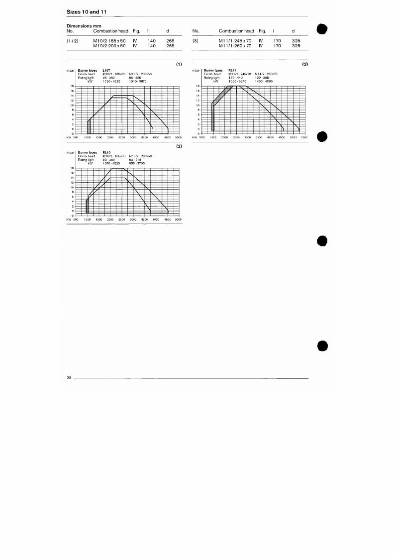
7/18/2019 M14 Thermal Fluid
http://slidepdf.com/reader/full/m14-thermal-fluid 381/486
,,
/ _
^
r
Sizes 10 and 11
Dimen sions nnm
No.
(1+2)
Combust ion head
M 1 0 / 2 - 1 8 5 x 5 0
M l 0 /2 - 2 0 0 x 5 0
Fig.
iV
IV
1
140
140
d
265
265
(1)
No.
(3)
Combust ion head
M 1 1 / 1 - 2 4 5 x 7 0
M i l / I - 2 6 0 x 7 0
Fig.
IV
IV
1
170
170
d
3 2 5
3 2 5
(3)
mbar
1 4
„
°
°
,
^
-
-2 •
Burner types
C o m b ,
head
Rating kg/h
k W
L10T
M l 0 / 2 - 1 8 5 x 5 0
9 5
-
380
1 1 3 0 - 4 5 2 5
M l 0 / 2 - 2 0 0 x 5 0
85 - 325
1 0 1 0 - 3 8 7 0
mbar
1 o
1 K
I D
. -
i n
l U
- 2 •
Burner types
C o m b , head
Rating kg/h
k W
y
y
' /
/
y
' ' i
RL11
M l 1/2-245x70
1 3 0 - 4 4 0
1 5 5 0 - 5 2 4 0
TC.
"•
S ^ : ^
M l 1 /2-260x70
1
2 0
-
3 8 5
1 4 3 0 - 4 5 8 5
S
1
1000 1500 2000 2500 3000 3500 4000 4500 5000 1600 2000 4000 4500 5000 5500
(2)
mbar
1 0
1 2
Burner types
C o m b ,
head
Rating kg/h
k W
RL10
M l 0 / 2 - 1 8 5 x 5 0
9 0 - 380
1 0 7 0 - 4 5 2 5
M l 0 / 2 - 2 0 0 x 5 0
8 0 - 3 1 5
9 5 5 - 3 7 5 0
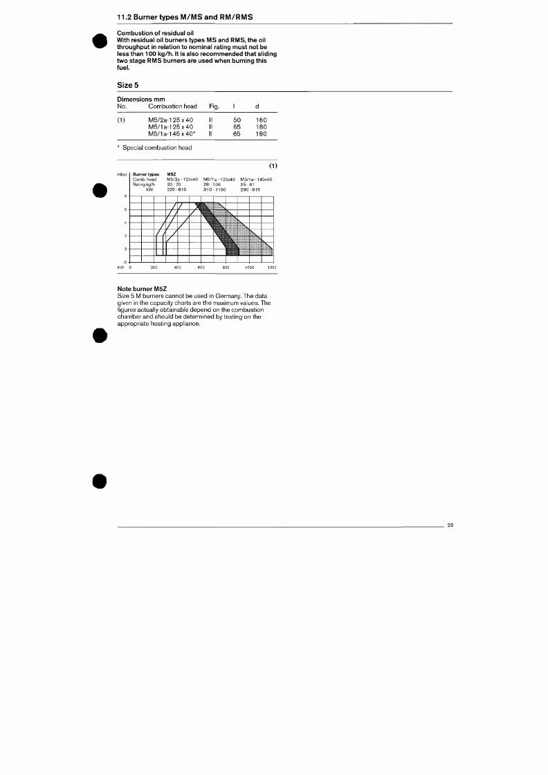
7/18/2019 M14 Thermal Fluid
http://slidepdf.com/reader/full/m14-thermal-fluid 382/486
.-
11.2 Burner types M /M S and R M /R M S
Combustion of residual oil
With residual oi l burners types M S and R MS , the oi l
throughput in relation to nominal rating must not be
less than 10 0 k g/ h. It is also recom me nde d that sl iding
two stage RMS burners are used when burning this
fuel.
Sizes
Dimensions mm
No.
Com bust ion head
( 1 ) M 5 / 2 a - 1 2 5 x 4 0
M 5 / 1 a - 1 2 5 x 4 0
M 5 / 1 a - 1 4 5 x 4 0 *
* Specia l combust ion head
Fig.
II
II
II
1
5 0
6 5
65
d
160
180
180
(1)
mbar
Burner types
C o m b ,
head
Rating kg/h
k W
M 5 Z
M 5 / 2 a - 1 2 5 x 4 0
2 0 - 7 0
2 2 5 - 8 1 0
M 5 / 1
2 8 -
3 1 0
a -1 2 5 x 4 0
0 6
1 1 9 0
v^~
M 5 /
2 5 -
2 8 0
a - 1 4 5 x 4 0
81
- 9 1 5
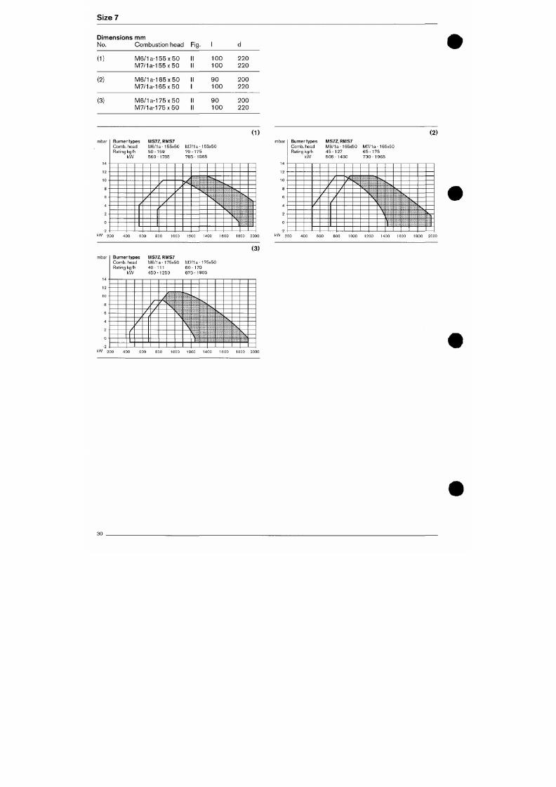
7/18/2019 M14 Thermal Fluid
http://slidepdf.com/reader/full/m14-thermal-fluid 383/486
Size?
Dimensions m m
No.
Combustion head
Fig.
(1)
(2)
(3)
M6/1a-155x50
M7/1a-155x50
M6/1a-165x50
M7/1a-165x50
M6/1a-175x50
M7/1a-175x50
II
II
II
1
II
II
100
100
9 0
100
9 0
100
220
220
200
220
200
220
(1)
mbar
14
- 2 H
Burner types
Comb, head
Rating kg/h
kW
/
MS7Z,
RMS7
M6/1a-155x50
50-159
560-1785
~L
7L.
/
/
/
M7/1a-155x50
70-175
785-1965
• v
(2)
mbar
14
-2 •
Burner types
Comb, head
Rating kg/h
kW
MS7Z,RMS7
M6/1a-165x50
45-127
505-1430
,,
/
/
/
'
y.
M7/1a-165x50
65-175
730-1965
\
1
k W 200 400 600 800 1000 1200 1400 1600 1800 2000
kW 200 400 600
800 1000 1200 1400 1600 1800 2000
(3)
mbar Burner types
MS7Z,
RMS7
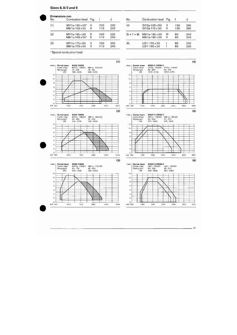
7/18/2019 M14 Thermal Fluid
http://slidepdf.com/reader/full/m14-thermal-fluid 384/486
Comb, head M6/1a-175x50 M7/1a-175x50
S iz e s 8 , 8 /2 a n d 9
Di men si o n s mm
No.
Com bust ion head Fig.
(1)
(2)
(3)
M 7 / 1 a - 1 5 5 x 5 0 * 1
M 8 / 1 a - 1 5 5 x 5 0 1
M 7 / 1 a - 1 6 5 x 5 0 1
M 8 / 1 a - 1 6 5 x 5 0 * 1
M 7 / 1 a - 1 7 5 x 5 0 1
M 8 / 1 a - 1 7 5 x 5 0 1
1 100
1 110
1 100
1 110
1 100
1 110
220
2 4 0
220
240
220
2 4 0
No.
(4)
(5+7 + 8)
(6)
Combust ion head
G7/2a-165 x 50
G 7 / 2 a - 1 7 5 x 5 0
M 9 / 1 a - 1 6 5 x 5 0
M 9 / 1 a - 1 8 5 x 5 0
U 2 / 1 - 1 5 5 x 5 0
U 2 / 1 - 1 6 5 x 5 0
Fig.
II
II
III
II
1
120
1 2 0
9 0
9 0
8 5
8 5
d
265
2 6 5
2 4 0
240
220
220
Specia l combust ion head
(1)
(4)
mbar
10
6
4
2
0
-2
Burner type:
Comb, head
Rating kg/h
kW
MS8Z, RMS8
M7/1a-155x50
7 0 - 2 0 6
7 8 5 - 2 3 2 0
M 8 / 1 a - 1 5 5 x 5 0
7 5 - 2 4 4
845 - 2740
_
mbar
-2 -
Burner types
Comb, head
Rating kg/h
kW
> ^
C^
MS8Z/2 ,
RMS8/2
G7/2a-165x50 G7/2a-175x50
9 5 - 2 8 0 9 0 - 2 7 4
1070-3155 1010-3075
•^
\
\
^\
\ \
\ \
S.S
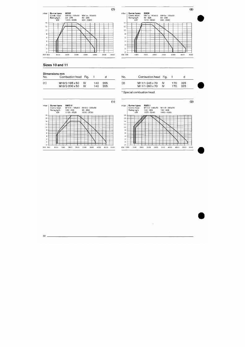
7/18/2019 M14 Thermal Fluid
http://slidepdf.com/reader/full/m14-thermal-fluid 385/486
(2) (5 )
(7)
(8)
mbar
1 4
"2 -
Burner types
Comb, head
Ra t ing kg /h
k W
/
/
/^
/
/
(
M S 9 Z
M 9 / 1 a - 1 6 5 x 5 0
9 0 - 2 7 5
1 0 1 0 - 3 0 9 5
7 ~
/L_
'T
/
N ,
'•
M 9 / 1 a - 1 8 5 x 5 0
8 0 - 2 6 5
9 0 0 - 2 9 8 0
mbar
14
- 2 •
Burner types
Comb, head
Ra t ing kg /h
k W
y
/
>/
/
>7
/
/
r
R M S 9
M 9 / 1 a - 1 6 5 x 5 0
9 0 - 3 2 8
1 0 1 0 - 3 6 9 0
cz
'
M 9 / 1 a - 1 8 5 x 5 0
8 0 - 265
9 0 0 - 2 9 8 0
Sizes 10 and 11
Dimensions mm
No.
Com bust ion head Fig.
(1)
M 1 0 / 2 - 1 8 5 x 5 0 IV 1 4 0 2 6 5
M l 0/2-200x50 IV 140 265
No.
Com bustion head Fig.
(2) M l
1/1-245x70
IV
M l
1/1-260x70
IV
* Specia l com bust ion head
1
170
170
d
325
325
(1)
mbar Burner types
Comb, head
Rating kg/h
k W
R M S 1 0
M l 0/2-185x50
1 0 0 - 4 0 3
1 1 2 5 - 4 5 2 5
M l 0 /2-200x50
9 0 - 3 3 4
1 0 1 0 - 3 7 5 0
(2)
mbar
Burner types
Comb, head
Ra t ing kg /h
k W
RMS11
M l 1 /2-245x70
1 4 0 - 4 6 6
1 5 7 5 - 5 2 4 0
M l 1 /2-260x70
1 3 0 - 4 0 8
1 4 6 0 - 4 5 8 5
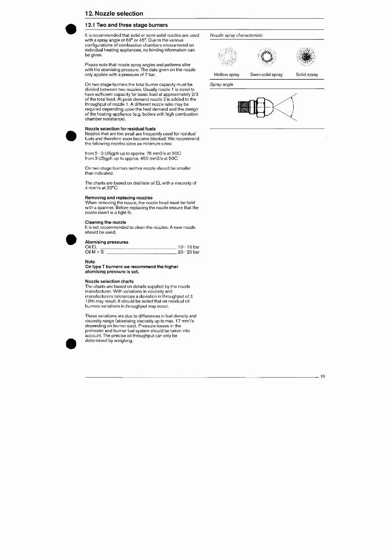
7/18/2019 M14 Thermal Fluid
http://slidepdf.com/reader/full/m14-thermal-fluid 386/486
JO
•>
12.
Nozz le se lec t ion
12.1 Two and three stage burners
I t is reco mm ende d that solid or semi-solid nozzles are used
with a spray angle of 60° or 45°. Due to the various
conf igurations of combust ion chambers encountered on
individual heating appliances, no binding information can
be given.
Please note that nozzle spray angles and patterns alter
with the atomis ing p ressure. The data given on the nozzle
only applies with a pressure of 7 bar.
On two stage burners the total burner capacity must be
divided be twee n two nozzles. Usually nozzle
1
is sized to
have suff icient capac ity for basic load at approximately 2/3
of the total
load.
At peak dem and nozzle 2 is ad de d to the
throughput of nozzle
1.
A different nozzle ratio may be
required depending upon the heat demand and the design
of the heating appliance (e.g. boilers with high c om bustio n
chamber resistance).
Nozzle spray characteristic
Hollo w spray Sem i-solid spray
Solid spray
Spray angle
Nozzle selec tion for residual fuels
Nozzles that are too small are frequently used for residual
fuels and therefore soon becom e blocked. W e recomm end
the following nozzles sizes as minimum s izes:
f rom 2 - 3 U Sg ph up to approx. 76 mm2/s at 5 0 C
from 3 US gph up to approx. 45 0 mm 2/s at 5 0 C
On two stage burners neither nozzle should be smaller
than indicated.
The charts are base d on dist i l late oil EL with a viscos ity of
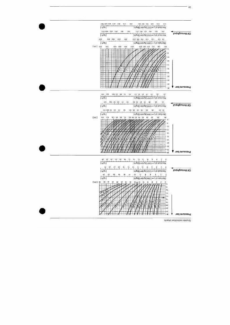
7/18/2019 M14 Thermal Fluid
http://slidepdf.com/reader/full/m14-thermal-fluid 387/486
t'S
08S oos ost' oot- ose
W i l ' I 1
[ 4/ß>l ]
005
081 091- O t't
_l_
OSI-
_ 1 _
oos 0S1? oot' ose
I MB> ]
[ 4 /6 > | ] [ , i i i p /ß > | ] ^ 6 ' 0 = ' ^ l O | B n p S 9 y
OSZ
0 0 5 081. 091. O t - l 051 - 0 01
oot" ose ooe
[4/6>|][,ujp/ß>|] e e o =^
\\o
lenpisay
001
06
[ 4/B>l ]
[ 4 /1 ] 009 oos
0 0 5
0 9 1 - 0 9 1
O f
I-
. I
,
. ,1 . . , I , I , I ,
0 5 1 .
I I I
001? ose ooe
0 S5
005 081 09 1 O t^ l 051 . 00 1
1111 111II i i i i IIII 1111 \y[\ W('\\V7P(''^
i>f ~
' ' ^'
/ ' ' ' ' ^ ' ' ' '
.<' ' « ' ' '
/''
y
i'/^i^t*
' ^ ^
/ ^ ' ' I ^ i ^ / ' ^ ^é.
'" ^ -/ '' 2,' i / ' Z^
/
y ^* // ^ / ^^j
j ' 2 7 I I ' > ^ Z v
1 / 2 / ^ f / i . ' / '
yfe_ Jfe_ /^gLjRil fe. fy - i ' ^ ty^J&v
,
^6
^
'cT
/ o / o " / o / o " /ö~| /cT ^ Q ^ ' ^ ö "
"""X^""^'^
^ ^ ^ ^ ' ^ ; i ^ i ^ ^ ^
^ — y ^ — - j ^ / ^ j^Å^--T^Y-}^x/^/^/ \
/ i / ^ -, Z J "i IT^
: : : : : : : : ? : : : : :V : : : : - ; / ; - ^ : :Z : : , . j ' i ; ^ ^ : : : : :: : : : -
:::::::r::::
:::-,?;^^::^:v±:, :::::::::::-
}ndL|ßnojL|; IJO
T jeq 3jnss3j(j
Ofrt 051
1 . 1 . 1 , 1 ,
[ 4/6>l
]
051
. , 1 . 1 .
1
[ 4/ß>l ]
1 1
OOl
11
3 0 1
l i n
0 6
n i l
36 08
1 . , , ,1
08
OZ
Oi
1
I I I
0 9
• I I I .
0 9
, 1 1
, ,
OS S I '
[M/ß>1]k
os st"
, l , , , l l , , , .
[4/Nk
ot' se 08
, , , 1 . . , . 1 . . . , 1 ,
Lup/ß>l]
i 6 ' 0 =
'if se oe
I I , , , 1 , , , ,1 , , ,
Lup/ß>i] ee'o =
S5 0 5
, , , 1 , 1 , 1
1,
k \\o
S5
, 1 ,
X| o
|Enp S9y
05
, , , 1, ,,
IBnpjssy
indLjBnojqi no
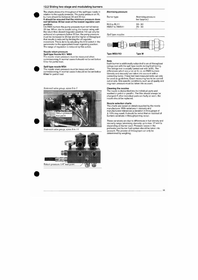
7/18/2019 M14 Thermal Fluid
http://slidepdf.com/reader/full/m14-thermal-fluid 388/486
12.2 Sliding tw o stag e and mo dulating burners
The charts show s the throu ghpu t of the spil l type nozzle in
relation to the supply pres sure. The pum p pressure on RL
burners should be between 20 and 30 bar.
I t should be ensured that the minimum pressure does
not fal l below 20 bar even at the lowest regulator c am
position.
On RMS burners the pump pressure must not fall below
25 bar. Whe n, due to nozzle sizing, the bu rner rating with
the return f low closed (regulator posit ion 10) can only be
achieved at a pressure below 25 bar, the pump pressure
must be increased to 25 bar and the higher oil throughput
that results is reduc ed by limit ing the oil regulator
movem ent. This is don e by adjusting the limit switch in the
servomotor to the appropriate lower regulating posit ion.
The range of regulation is reduc ed by this action.
Nozzle return pressure
Spil l type N ozzle K3
/
W B3
The nozzle return pressure must be measured when
commissioning. In normal cases it should not be set below
5 bar for partial load.
Spil l type nozzle W S4
The nozzle return pressure must be measured when
commissioning. In normal cases it should not be set below
8
ba r
for partial load.
Atomising pressure
Burner type Atomising pressure
bar (approx.)
R L 5 t o R L 1 1
R M S 7 t o R M S 1 1
2 0 - 3 0
2 5 - 3 0
Spill type nozzles
T y p e W B 3 / K 3
TypeW
Note
Each burner is additionally subje cted to an oil throughpu t
ratings test w ith the spil l type nozzle during f inal testing.
This ratings test is usually carried out with oil EL. The
differences which occ ur on oil S, i.e. on RM S burners
(density and viscosity) are taken into accoun t with a
correcting factor. These test bed measurements can only
be used as guidelines. Exact measuring has to be carried
out on site. Site specif ic co ndit ion s, such as oil quality and
ring main pressure must be taken into account.
Solenoid valve group, sizes 5 to 7
Cleaning the nozzles
The nozzle is dismantled into its individual parts and
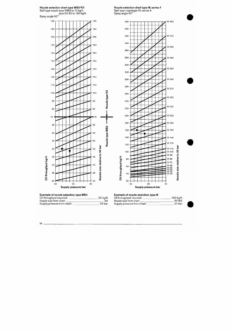
7/18/2019 M14 Thermal Fluid
http://slidepdf.com/reader/full/m14-thermal-fluid 389/486
was hed in petrol or paraff in. The f ilter should alway s be
Nozzle selection chart type W B3 /K3
Spill type nozzle type W B 3 to 70 kg/h
type K3 80 to 180 kg/h
Spray angle 50 °
Nozzle selection chart type W, series 4
Spill type nozzletype W, series 4
Spray angle 50°
190 190
CO
^
Q.
N
N
O
4 6 0
4 4 0
4 2 0
4 0 0
3 8 0
3 6 0
3 4 0
3 2 0
3 0 0
2 8 0
2 6 0
2 4 0
2 2 0
W 4 6 0
y^ A2Q
W 3 9 0
W 3 6 0
W 3 3 0
W 3 0 0
W 2 7 5
W 2 5 0
W 2 2 5
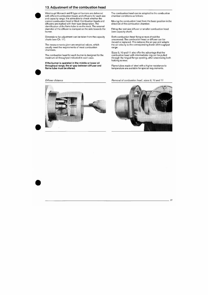
7/18/2019 M14 Thermal Fluid
http://slidepdf.com/reader/full/m14-thermal-fluid 390/486
13.
Ad jus tmen t of the co m bus t ion head
We ishaup t M onarch and R type oil burners are delivered
with different com bustion he ads and diffusers for each size
and capa city range. It is advisable to ch eck whe ther the
correct com bust ion head is f i t ted. Combu st ion heads and
diffusers are marked with their type design ation. The
identification of the flame tube is on the neck. The external
diameter of the diffuser is stam ped on the side towa rds the
burner.
Dimensions for adjustment can be taken from the capacity
charts (see Ch . 11).
The measurem ents given are empirical values, which
usually meet the requirements of most combustion
chambers.
The combustion head for each burner is designed for the
maximum oil throughput indica ted in each case .
If the burner is operated in the middle or lower oil
throughput range, the air gap betwe en diffuser and
flame tube must be altered.
The combust ion head can be adap ted to the combus t ion
cham ber condit ions as fo l lows:
Moving the combustion head from the basic posit ion in the
direct ion of the combust ion chamber.
Fitt ing the next size diffuser or smaller com bustion head
(see capacity ch art).
Bo th com bust ion head f ix ing screws should be
unsc rewed .
The comb ustion head or diffuser can b e
moved or replaced. This reduces the air gap and adapts
the air velocity to the corres pond ing lower oil throughpu t
range.
Sizes 9, 10 and 11 also offer the advan tage that the
combustion head with intermediate ring can be pulled
through the hinged f lange opening, after unscrewing both
hold ing screws.
Flame tubes m ade of steel with a higher resistance to
tem peratu re are available for spec ial req uirements.
Diffuser distance
Removal of combustion liead, sizes 9, 10 and 11
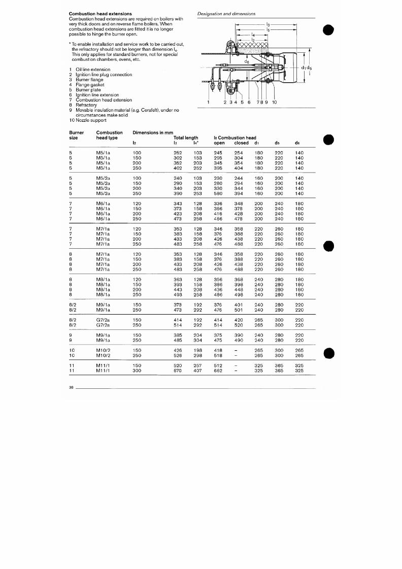
7/18/2019 M14 Thermal Fluid
http://slidepdf.com/reader/full/m14-thermal-fluid 391/486
Connbustion head extensions
Combustion head extensions are required on boilers with
very thick doors and on reverse f lame boilers. When
com bustio n he ad extensions are f it ted it is no longer
possible to hinge the burner open.
* To enable installat ion and service work to be c arried out,
the refractory sh ould not be longer than dime nsion I4.
This only applies for standard b urners, not for s pecia l
com bust ion chambers, ovens, etc.
1 Oil l ine extension
2 Ignit ion line plug conn ection
3 Burner f lange
4 Flange gask et
5 Burner plate
6 Ignition line extensio n
7 Co mb ustio n head extension
8 Refractory
9 M ovable insulation material (e.g. Cerafelt), under no
circum stances make sol id
10 Nozzle support
Designation and dimensions
1 2 3 4 5 6 7 8 9 10
Burner
size
Combust ion
l iead type
Dimensions in mm
I2
Total length
l3 U*
Is Com bustion head
open closed di
ds
d6
5
5
5
5
5
5
5
M5/1a
M5/1a
M5/1a
M5/1a
M5/2a
M5/2a
M5/2a
100
150
200
250
100
150
200
252
302
352
402
240
290
340
103
153
203
252
103
153
203
245
295
345
395
230
280
330
254
304
354
404
244
294
344
180
180
180
180
160
160
160
220
220
220
220
200
200
200
140
140
140
140
140
140
140
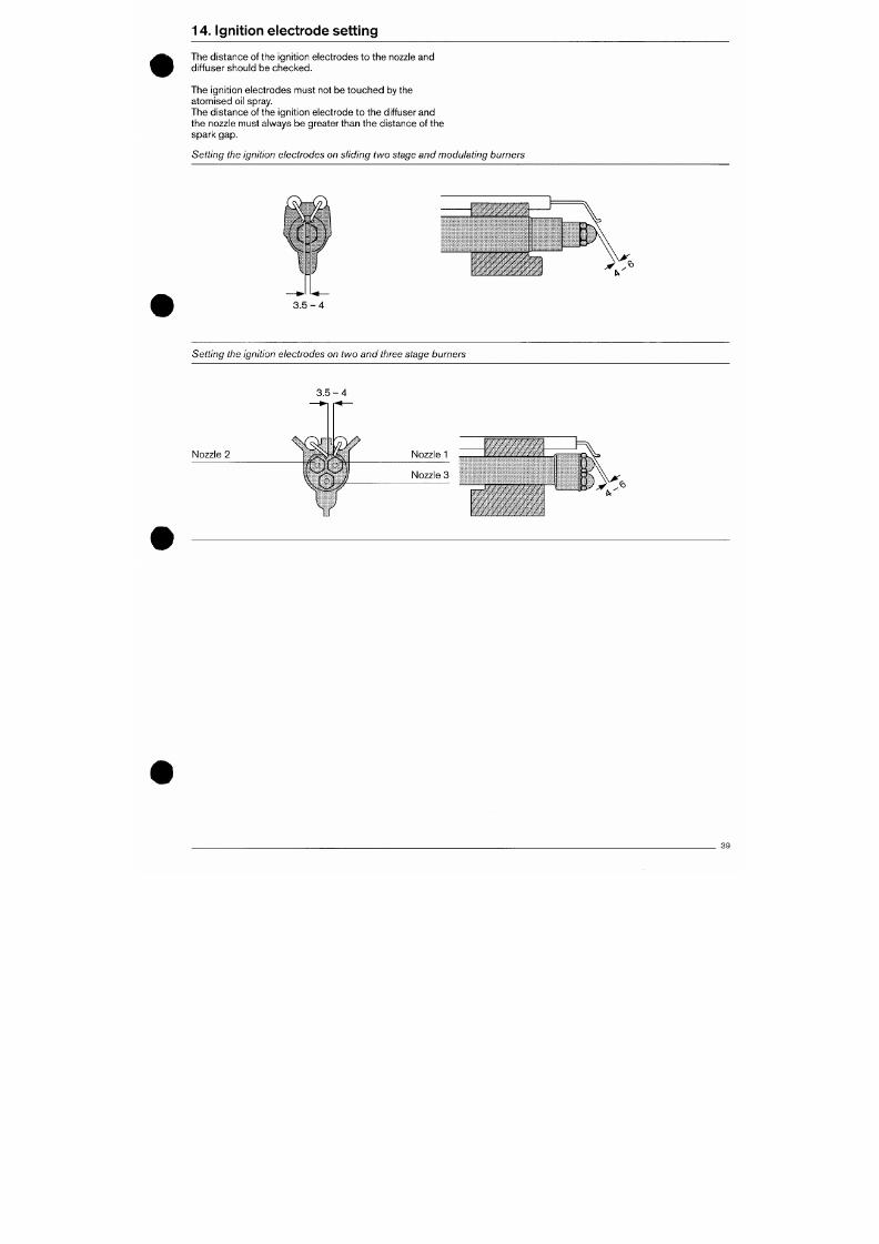
7/18/2019 M14 Thermal Fluid
http://slidepdf.com/reader/full/m14-thermal-fluid 392/486
14. Ign i tion e lec t rod e s et t ing
The distan ce of the ignit ion electro des to the nozzle and
dif fuser should be chec ked.
The ignit ion electrodes must not be touched by the
atom ised oil spray.
The distance of the ignit ion electrode to the diffuserand
the nozzle must always be greater than the distan ce of the
spark gap.
Setting the ignition electrodes on sliding two stage and modulating burners
3 . 5 - 4
Setting the ignition electrodes on two and three stage burners
3 . 5 - 4
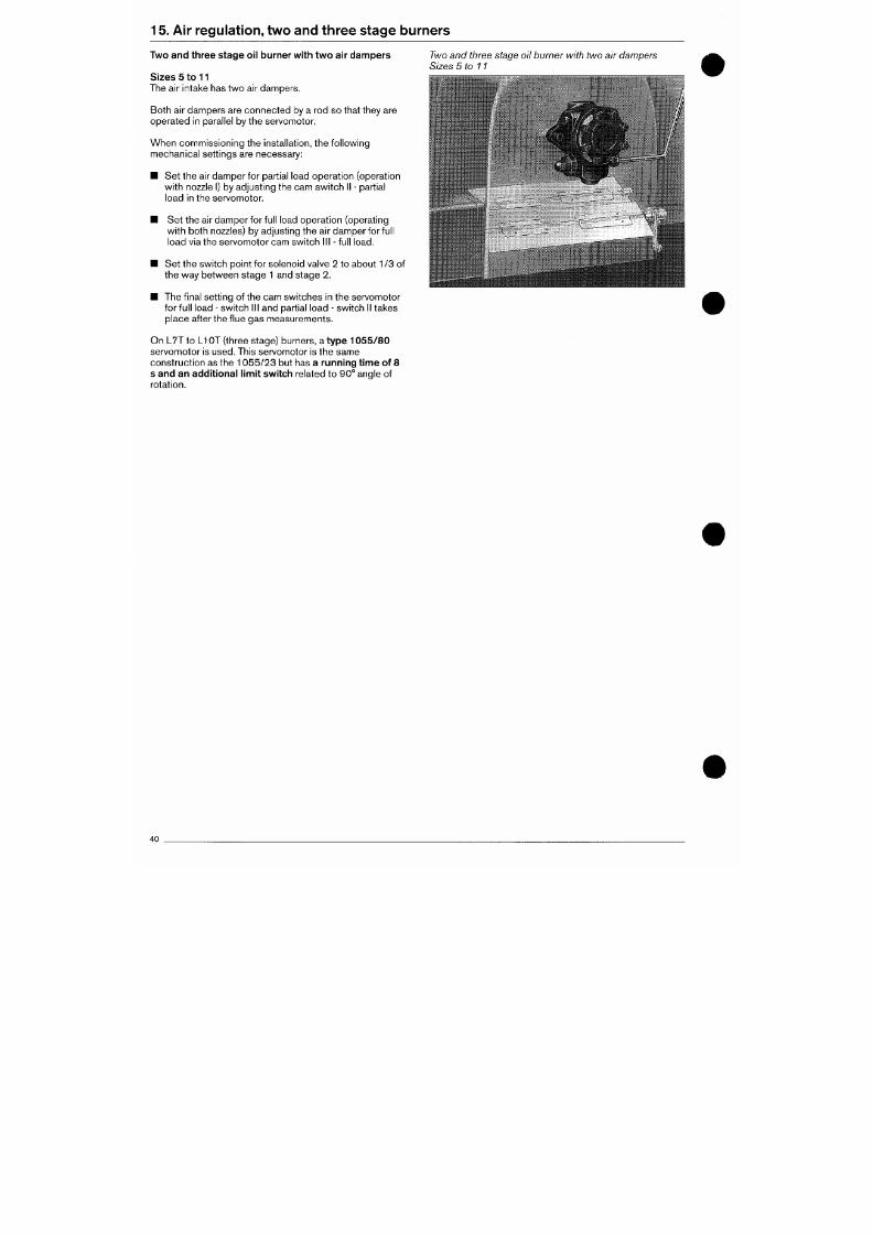
7/18/2019 M14 Thermal Fluid
http://slidepdf.com/reader/full/m14-thermal-fluid 393/486
15 . Air regulation, two and three stage burners
Two and three stag e oi l burner with two air d am pers
Sizes 5 to 11
The air intake has two air dampers.
Bo th air dampers are con nec ted by a rod so that they are
ope rated in parallel by the servomotor.
When commissioning the installat ion, the following
mechanical sett ings are necessary:
• Set the air damp er for part ial load opera tion (operation
with nozzle I) by adjusting the cam switch II - partial
load in the servom otor.
Two and three stage oil burner with two air dampers
Sizes 5 to 11
• Set the air dam per for full load opera tion (operating
wit h b oth nozzles) by adjusting the air damper for full
load via the servom otor cam switc h III - full load.
• Set the switch point for solenoid valve 2 to about
1
/3 of
the way between stage 1 and stage 2.
• The f inal sett ing of the cam switc hes in the servomotor
for full load - switch III and partial load - switch II takes
place after the f lue gas measurements.
On L7T to LI OT (three stage) burners, a t yp e 1 0 5 5 / 8 0
servom otor is used. This servomotor is the same
construct ion as the 1055/23 but has a running time of 8
s and an additional l imit switch
related to 90° angle of
rotat ion.
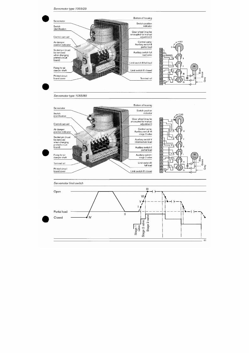
7/18/2019 M14 Thermal Fluid
http://slidepdf.com/reader/full/m14-thermal-fluid 394/486
Servomotor type 1055/23
Servomotor
Air damper
posi t ion ind icator
Socket p in (must
be removed
when changing
prin ted c i rcu i t
board)
Fixing for air
damper shaf t
Pr in ted c i rcu i t
board cover
.
^
' S » « « , ,
....•:- ,rt
r m m
H -
..
Bot tom
o f
housing
Switch posi t ion
indicator
Gear wheel (may
be
uncoupled for manual
adjustment)
Con t ro l cams:
Auxil iary switch
II
part ial load
Auxil iary switch full
load valve
Limit switch II I full load
Limit swi tch IV c losed
Terminal rail
Servomotor type 1055/80
Bot tom
o f
housing
Servomotor
Sw i t ch
identif ication
Switch posi t ion
ind icator
Gear wheel (may be
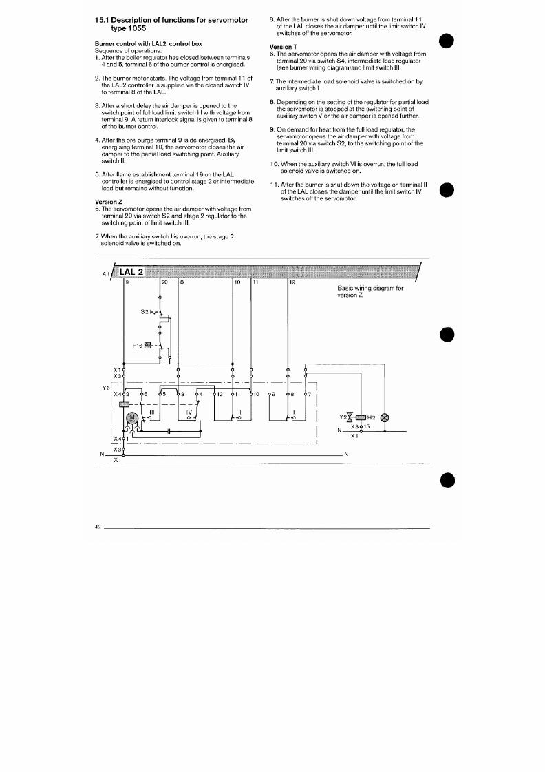
7/18/2019 M14 Thermal Fluid
http://slidepdf.com/reader/full/m14-thermal-fluid 395/486
15.1 Desc r ip t ion o f fun c t ion s fo r se rvo mo to r
type 1055
Burner control with LAL2 control box
Sequenc e of operat ions:
1. After the boiler regulator has clo sed betw/een terminals
4 and 5, terminal 6 of the burner control is energ ised.
2.
The burner m otor starts. The voltag e from terminal 11 of
the LAL2 controller is supplied via the closed switch IV
to terminal 8 of the LAL.
3. After a short delay the air dam per is opened to the
switc h point of full load limit switc h III with voltage from
terminal 9. A return interlock sig nal is given to terminal 8
of the burner con trol.
4. After the pre-purge terminal 9 is de-energised. By
energising terminal 10, the serv omo tor closes the air
dampe r to the part ial load switch ing point. Auxiliary
switc h II.
5. After f lame establishm ent term inal 19 on the LA L
controller is energised to control stage 2 or intermediate
load but remains without function.
Version
Z
6. The servomotor opens the air damper with voltage from
terminal 20 via switch S2 and stage 2 regulator to the
switching point of l imit switch III .
7. W hen the auxil iary switch I is overrun, the stage 2
solenoid valve is switched on.
8. After the burner is shut dow n voltag e from terminal 11
of the LAL closes the air damp er until the limit switc h IV
switches off the servomotor.
Version T
6. The servomotor opens the air damper with voltage from
terminal 20 via switch S4, intermediate load regulator
(see burner wiring diagram )and limit switch III .
7. The intermediate load solenoid valve is switched on by
auxiliary sw itch I.
8. Dep ending on the sett ing of the regulator for part ial load
the servomotor is stopped at the switching point of
auxil iary switch V or the air dam per is opened further.
9. On demand for heat from the full load regulator, the
servomotor opens the air damper with voltage from
terminal 20 via switch S2, to the switching point of the
limit switch III.
10. W hen the auxil iary switc h VI is overrun, the full load
solenoid valve is switched on.
1 1 . A fter the burner is shut dow n the voltage on terminal I I
of the LAL closes the da mp er until the limit switch IV
switches off the servomotor.

7/18/2019 M14 Thermal Fluid
http://slidepdf.com/reader/full/m14-thermal-fluid 396/486
15.2 Setting the cam s limit and auxil iary
switches on servomo tor type 1055
Th e air damp er po sit ion is indicate d o n a scale of 0° to 90 °
by a pointer on the shaft.
There is a set ting scale between the cam sw itches. The
set t ing knobs on the cam switch po int to this scale with a
small pointer and give the switching point of the
appropriate switch in relat ion to the air damper posit ion.
The cam s witches are set as fol lows using the se t t ing
scale:
Ca m swi tches
* VI - Auxiliary switch
Stage 3 valve
Dep ende nt on burner rat ing,
but set below V
* v -
I V -
I I I -
I I -
Auxiliary s witc h
Intermediate loa d -
air
Limit switch closed
Limit switch
Full load
Auxiliary s witc h
Partial load
Dep ende nt on burner rat ing,
set between
i
and IV
for air sett ing
0°
Dep ende nt on burner rat ing,
up to 80°
Dep ende nt on burner rating,
betw een 0 and approx. 5 0°
Auxiliary s witc h
Stage 2 valve
Dependent on burner rat ing,
between part ia l and
intermediate load at approx.
10° to 40°
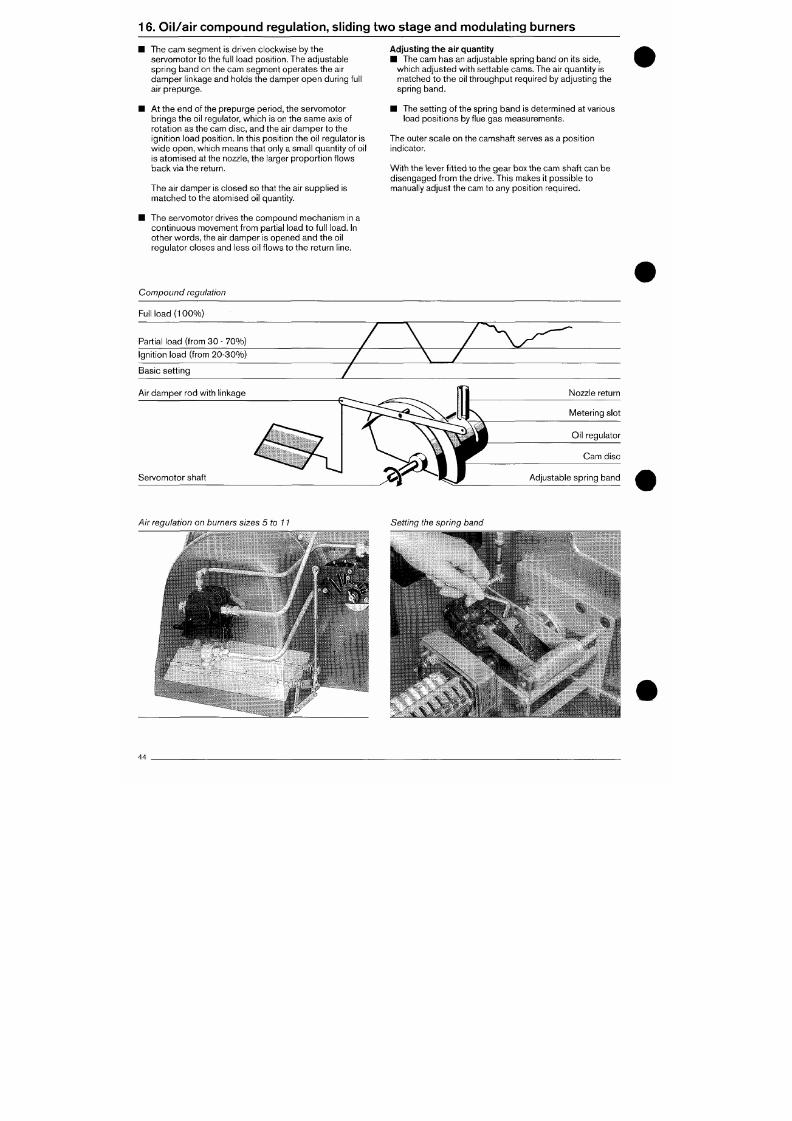
7/18/2019 M14 Thermal Fluid
http://slidepdf.com/reader/full/m14-thermal-fluid 397/486
16.
Oil/a ir compound regulation, sliding two stage and modulating burners
The cam segment is driven clocl<wise by the
servomotor to the full load posit ion. The adjustable
spr ing band on the cam segm ent ope rates the air
dam per l inkage and holds the damper ope n dur ing full
a i r prepu rge.
At the en d of the prepurge per iod, the servom otor
bring s the oil regulator, wh ich is on the sam e axis of
rotat ion as the cam disc, and the air damper to the
ignit ion load p osit ion. In this po sit ion the oil regulator is
wide open, which means that only a small quantity of oil
is atomised at the nozzle, the larger proport ion f lows
bac k via the return.
The air damper is closed so that the air supplied is
matched to the atomised oil quantity.
Adjusting the air quantity
• The cam has an adjustab le spring band on its side,
which adjusted with settable cams. The air quantity is
matched to the oi l throughput required by adjust ing the
spr ing band.
• The sett in g of the spring band is determ ined at various
load posit ions by f lue gas measurements.
The outer scale on the camshaft serves as a posit ion
indicator.
W ith the lever f i t ted to the gear box the cam shaf t can be
disengaged from the drive. This makes it possible to
manually adjust the cam to any posit ion required.
The servomotor dr ives the comp ound mechanism in a
continuous movement from part ial load to full load. In
other wo rds, the air damper is opened and the oil
regula tor clo ses and less oil flow s to the return l ine.
Compound regulat ion
Full load (10 0% )
Part ial load (from 30 - 70%)
Igni tion load ( from 20 -30% )
Basic set t ing
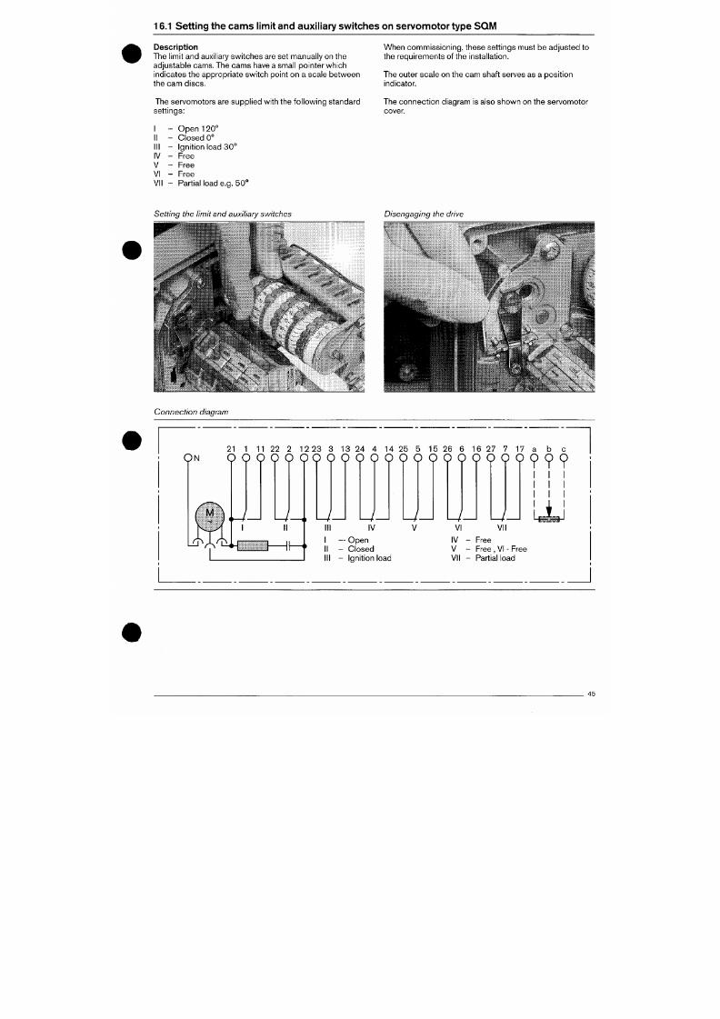
7/18/2019 M14 Thermal Fluid
http://slidepdf.com/reader/full/m14-thermal-fluid 398/486
16.1 Setting the cam s limit and auxil iary switches on servom otor type SQM
Descript ion
The limit and auxiliary switches are set manually on the
adjustable cams. The cams have a small pointer which
indicates the appropriate switch point on a scale between
the cam discs.
Wh en com missioning, these sett ings must be adjusted to
the requirem ents of the installat ion.
The outer scale on the cam shaft serves as a po sit ion
indicator.
The servomotors are suppl ied with the fo l lowing standard
set t ings:
I - Ope n 120°
II - C los ed 0°
III - Ignition load 30 °
IV - Free
V - Free
VI - Free
VII - Partial load e.g. 50 °
The connection diagram is also shown on the servomotor
cover.
Setting the limit and auxiliary switches
• ^ .
.8.-
•9»
Disengaging the drive
.^-.r |f lT;. .ä-
i
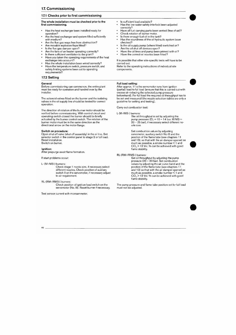
7/18/2019 M14 Thermal Fluid
http://slidepdf.com/reader/full/m14-thermal-fluid 399/486
17.
Com missioning
17.1 Checks prior to first c om m issioning
The w hole installat ion m ust be chec ked prior to the
first com missioning.
• Has the heat exchanger been installed ready for
opera t ion?
• Are the heat exchanger and system fil led suff iciently
w i th med ium?
• Are the f lue gas ways f ree f rom ob struct ion?
• Ar e movable explosion f laps f it ted?
• Is the f lue gas damper open?
• Ar e the fans of air heater operating co rrectly?
• Is there suff icient ventilat ion to the plant?
• Have you taken the operating requiremen ts of the heat
exchanger in to account?
• Has the who le installation been wi red correctly?
• Have the temperature switch, pressure switch, and
safety l imit ing systems been set to operating
requirements?
17.2 Setting
Is suff icient load available?
Has the low water safety interlock been a djusted
cor rect ly?
Have all fuel carrying p arts been vented (free of air)?
Check rotation of burner motor.
Is there enough fuel oil in the tank?
Has the soundness of the oil hydraulic system been
ch e cke d ?
Is the oil supply pump (where f it ted) switched on?
Are the oil shut off devices open?
Have the oil l ines and pump been primed with oil?
Have the correct oil nozzles been f it ted?
It is possib le that other site-spec if ic tests w ill have to be
carried out.
Refer to the operating ins tructions of individual site
components .
General
Before comm issioning can com menc e, the entire p lant
must be ready for operation and ha nde d over by the
installer.
The sole noid valves fit ted on the burner and the isolating
valves in the oil supply l ine should be te ste d for correc t
operat ion.
The direction of rotation of the burner motor should be
verif ied before commissioning. With control circuit and
Full load setting:
After approx. 11 s the servom otor runs from ignition
(partial) load to full load (ensure that this is carried out with
excess air reducing the selected pump pressure
beforeh and). For full load the required oil throug hput has to
be set and m easured (the nozzle selection tables are only a
guideline for sett ing and testing).
Carry out combustion test:
L-(M-/MS-) burners:
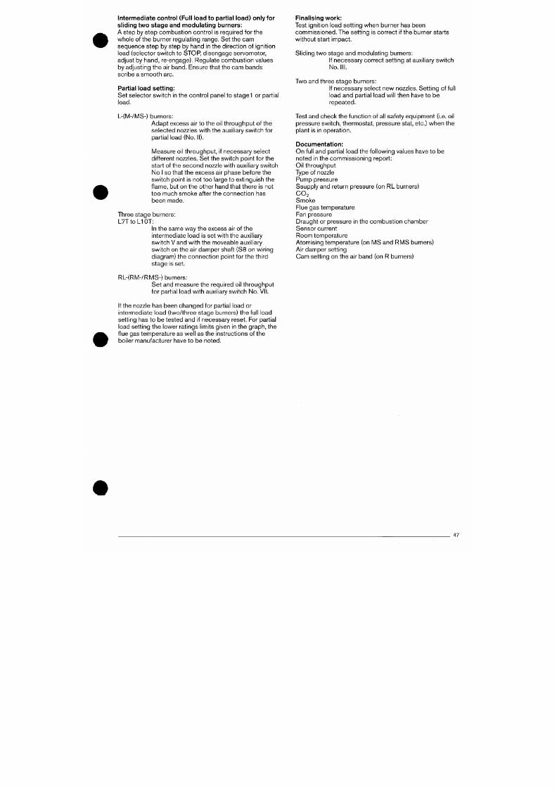
7/18/2019 M14 Thermal Fluid
http://slidepdf.com/reader/full/m14-thermal-fluid 400/486
Interm edia te control (Full load to partial load) only for
sl iding two st age and modu lating burners:
A step by step combustion control is required for the
whole of the burner regulating range. Set the cam
sequen ce st ep by step by hand in the direction of ignit ion
load (selector switch to STOP, disengage servomotor,
adjust by hand, re-engage). Regulate combustion values
by adjusting the air band. Ensure that the cam bands
scribe a smooth arc.
Partial load setting:
Set selector switch in the control panel to stage
1
or partial
load.
L-(M-/MS-) burners:
Ad apt excess air to the oil throug hput of the
selec ted nozzles with the auxiliary sw itch for
partial load (No . II).
Measure oil throughput, if necessary select
different nozzles. Set the switch point for the
start of the sec ond nozzle with auxil iary s witch
No I so that the excess air phase before the
sw itch point is not too large to extinguish the
f lame,
but on the other hand that there is not
too much smoke after the connection has
been made.
Three stage burners:
L7T to LI OT:
in the same way the excess air of the
intermediate load is set with the auxiliary
sw itch V and with the moveable auxil iary
switch on the air damper shaft (S8 on wiring
diagram) the connection point for the third
sta ge is set.
Finalising wor k:
Test ignit ion load sett ing when burner has been
com mis sione d. The sett ing is corre ct if the burner starts
without start impact.
Sliding two stage and modulating burners:
If necessa ry co rrect s ett ing at auxiliary sw itch
No.
III.
Two and three stage burners:
If necessary select new nozzles. Sett in g of full
load and partial load will then have to be
repeated.
Test and check the function of all safety equipment (i.e. oil
pressure switch, thermostat, pressure stat, etc.) when the
plant is in operation.
Documentat ion:
On full and part ial load the followin g values have to be
noted in the commissioning report:
Oil throughput
Type of nozzle
Pump pressure
Ssupply and return pressure (on RL burners)
CO2
Smoke
Flue gas temperature
Fan pressure
Draught or pressure in the combustion chamber
Sensor current
Room tem perature
Atomising temperature (on M S and RM S burners)
Air damper sett ing
Cam sett ing on the air band (on R burners)
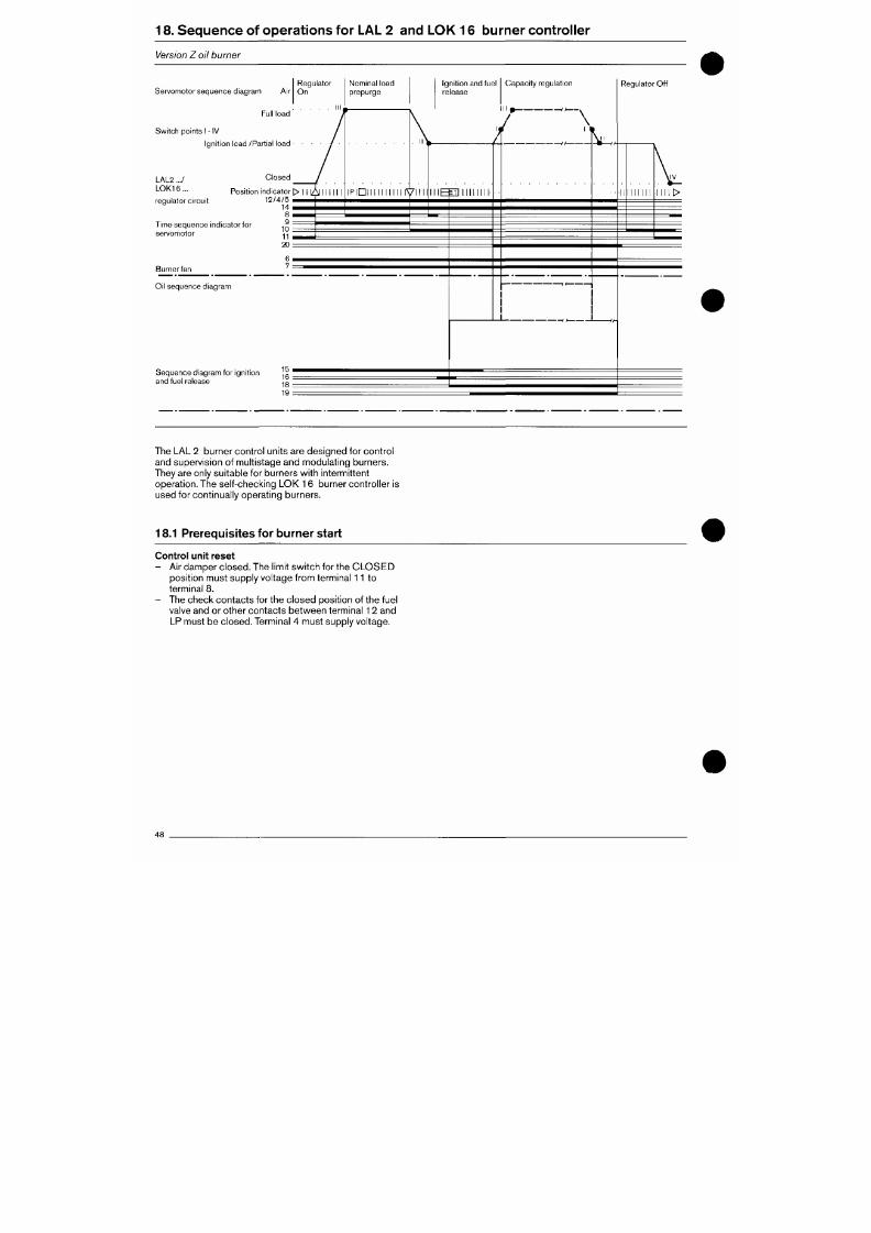
7/18/2019 M14 Thermal Fluid
http://slidepdf.com/reader/full/m14-thermal-fluid 401/486
18.
Se qu en ce of op era t ion s for LAL 2 and LOK 16 burn er co ntro l ler
Version Z oil burner
Servomo tor sequ ence d iagram Air
Full load
Switch points I - IV
Ignit ion load /Part ial load
Regulator
O n
LAL2 .../
L O K 1 6 .
C losed
Posi t ion ind icator 1> I 1 1 ^ 111 11 I
r eg ul ato r c ir cu it 1 2 / 4 / 5 ^ ^ ^
Time sequence ind icator for
servomotor
Burner fan
Oi l sequence d iagram
14 I
8 I
9 :
10 :
11 I
2 0 :
6 i
7 :
Nominal load
prepurge
ignit ion and fuel
re lease
Capaci ty regulat ion
/
I P I D I I I I I I I I I I I V I I I I
I I I
Seq uenc e d iagram for ign i t ion 15 '
and fuel release ^o
19
I ] I I I 1 1 1 I I '
-If
• -
Regulator Off
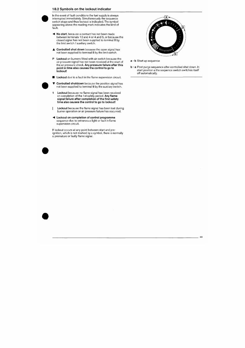
7/18/2019 M14 Thermal Fluid
http://slidepdf.com/reader/full/m14-thermal-fluid 402/486
18.2 Symbols o n the lockout indicator
In the event of fault con dit ions the fuel supply is always
interrupted immediately. Simultaneously the sequence
switch stops and thus lockout is indicated. The symbol
appea ring above the reading mark indicates the kind of
fault.
M No start,
because a contact has not been made
between terminals
1
2 and 4 or 4 and 5, or because the
closed signal has not been supplied to terminal 8 by
the limit switch / auxiliary switch.
• Controlled shut dow n because the open signal has
not been supplie d to terminal 8 by the limit sw itch.
P Lockout
on burners f it ted with air switch because the
air pressure signal has not been received at the start of
the air pressure che ck. Any pressure failure after this
point in time also causes the control to go to
lockout
• Lockout
due to a fault in the f lame supervision circu it.
• Controlled shutd own because the posit ion signal has
not been supp lied t o terminal 8 by the auxil iary switc h.
1 Lockout because no f lame signal has been received
on completion of the
1
st safety period .
Any f lam e
signal failure after completion of the first safety
t ime also cause s the control to go to lockout
I Lockout beca use the f lame signal has been lost du ring
burner operation or air pressure failure has occu rred .
A Lockout on com pletion of control program me
a
- b Start up sequence
b -
a
Post purge sequence after controlled shut down. In
start posit ion a the sequence switch switches itself
off automatically.
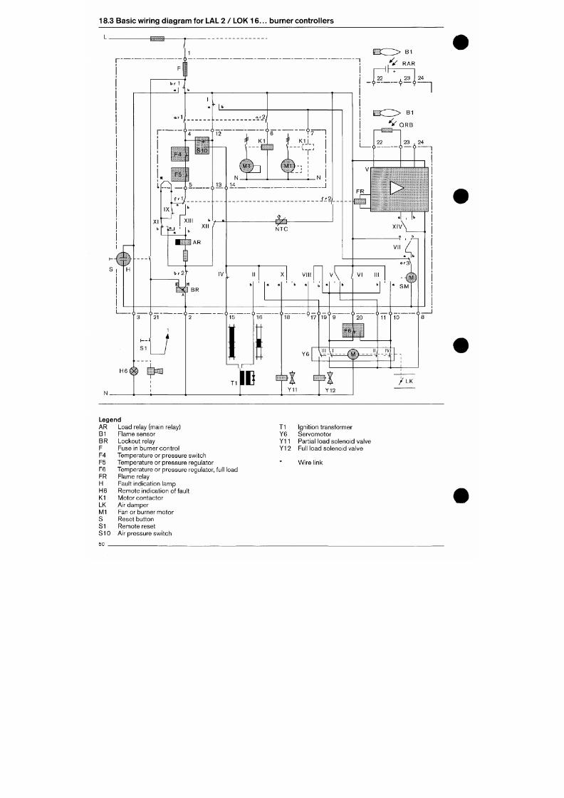
7/18/2019 M14 Thermal Fluid
http://slidepdf.com/reader/full/m14-thermal-fluid 403/486
18.3 Basic wiring diagram for LAL 2 / LOK 16 ... burner controllers
V RAR
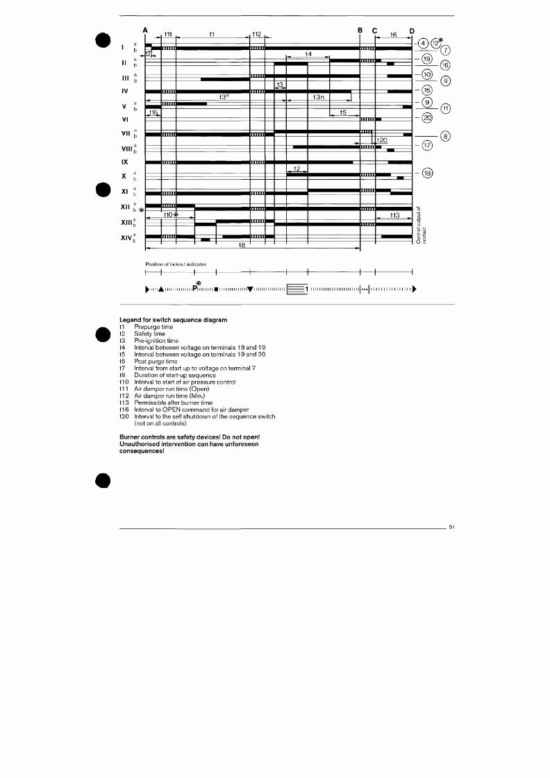
7/18/2019 M14 Thermal Fluid
http://slidepdf.com/reader/full/m14-thermal-fluid 404/486
I
I I
I I I
IV
V i
V I
V I I
,
V I I I ,
IX
X
X I
XI I
X I I I
X I V
\
E
JM.
^
^
til
m m
nnn
nnn
m m
tioJ
nnn
ti
t 3 "
(• ^
t12
l l l l U
nnn
nnn
r m n
nnn
« 9, t6 ?
i ^
^
^
^^ -
^
-
t4 .
. t 2 .
t 3 n
. t5 .
t 8
•"
nnn
i i i i i i
Mill
t 2 0
TTIfTT
m m :
'^~^~
—
^m
. t13 .
^^^^^^^^^^^^M
-(^f^
- 6 0 )
- (§)
(
- @
M -
"5
Q .
0
"5 'S
-t to
S
c
0 O
Position of locl<out indicator
®
®
®
®
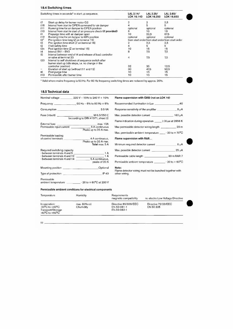
7/18/2019 M14 Thermal Fluid
http://slidepdf.com/reader/full/m14-thermal-fluid 405/486
18.4 Sw itching t imes
Sw itching t imes in seconds* in star t up sequence.
LAL 2 .1
4 /
LOK 16.1
4 0
2
4
optional
6
10
opt ional
LAL 2.25/
LOK 16.250
2
5
optional
10
22,5
optional
LAL 2.65 /
LOK 16.650
2,5
5
optional
10
67,5
opt ional
f rom start orde rf rom star t orderf rom star t order
2
4
10
8
2,5
5
15
7,5
2,5
5
15
7,5
t7
t16
t i l
t lO
t1
t12
t3 "
t3
t2
t3n
t4
t5
t20
t6
t13
Start up delay for burner motor G2
Interval f rom star t to O PE N comm and for air dam per
Running t ime for air damper to OP EN posi t ion
Interval from s tart to start of air pressure ch eck ( if pro vid ed )
Prepurge t ime with air damp er o pen
Running t ime for air damper to M IN posi t ion
Pre-ignit ion t ime long (Z on terminal 15)
Pre-
ignit ion t ime short (Z on terminal 16)
(1
st) safety t ime
Post ign it ion t ime (Z on terminal 15)
Interval BV1 - BV2
Interval between end of t4 and release of load controller
or valve at terminal 2 0
Interval to self shutdown of sequence switch after
burner sta rt up ( idle steps, i.e. no change in the
controller posit ion)
Durat ion of start up (without t11 and 12)
Post purge t ime
Permissible after burner t ime
7,5 7,5
3 2
3 0
10
10
3 5
47,5
15
15
12,5
92,5
15
15
' Val id where m ains frequency is 50 Hz. For 60 Hz f requency sw itching t imes are reduced by approx. 20% .
18.5 Technical data
Nominal vol tage
Frequency
Consumpt ion
.
220 V - 15 % t o 240 V + 1 0%
50 Hz - 6% to 60 Hz + 6 %
3.5 VA
Flame supervision with QR B (not on LOK 1 6)
Reco mm ende d i l luminat ion in Lux
Response sensit ivity of the amplif ier
4 0
B i j A
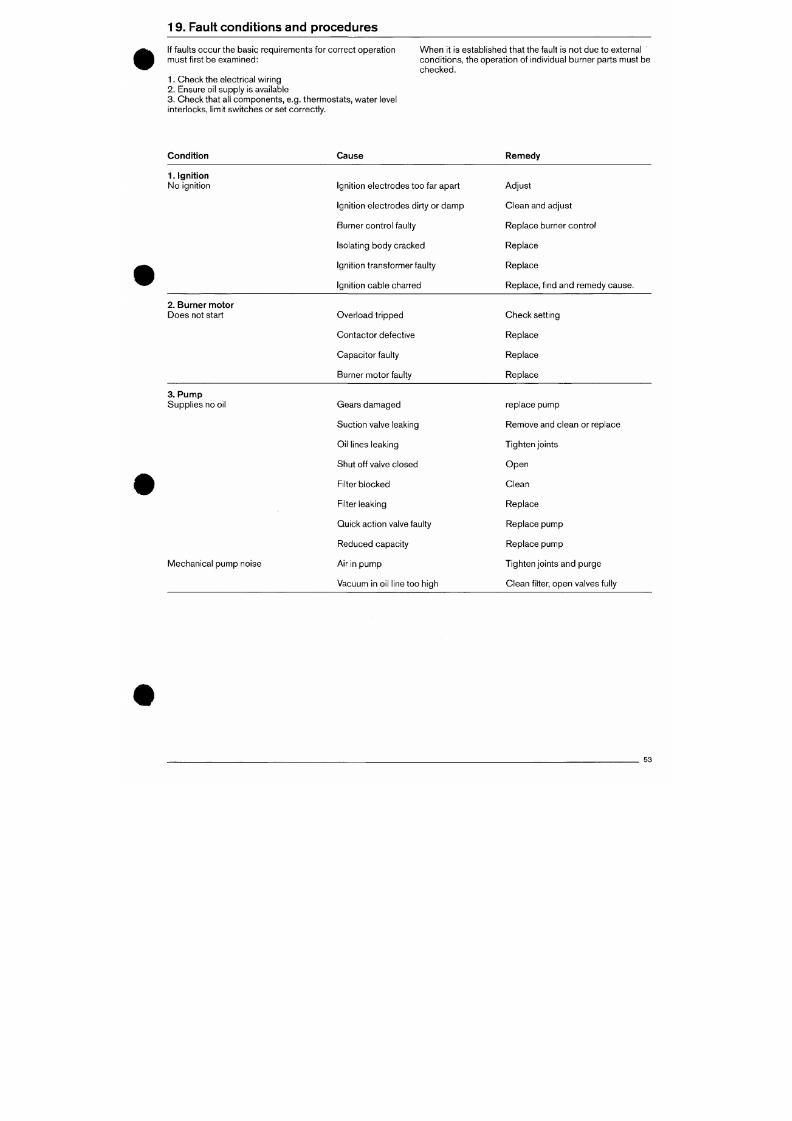
7/18/2019 M14 Thermal Fluid
http://slidepdf.com/reader/full/m14-thermal-fluid 406/486
19 . Faul t con d i t ions and proce dures
If faults occur the basic re quirements for correct operation
mus t f irst be examined:
1.
Check the electrical wiring
2.
Ensure oil supply is available
3. Check that all components, e.g. thermostats, water level
interlocks, l imit switch es or set correctly.
When it is established that the fault is not due to external
condit ions, the operation of individual burner parts must be
checked.
Condit ion
Cause
Remed y
1. Ignition
No ignit ion
Ignition electrod es too far apart
Ignit ion electrodes dirty or damp
Burner con trol faulty
Isolating body cracked
Ignition transformer faulty
Ignition cable charred
Adjust
Clean and adjust
Replace burner control
Replace
Replace
Replace, f ind and remedy cause.
2.
Burner motor
Does not start
Overload t r ipped
Contactor defect ive
Capacitor faulty
Burner motor faulty
Check set t ing
Replace
Replace
Replace
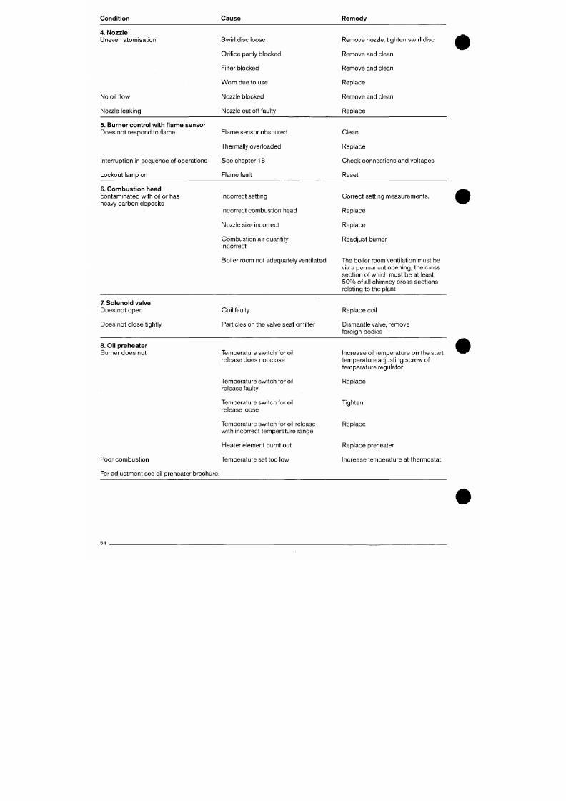
7/18/2019 M14 Thermal Fluid
http://slidepdf.com/reader/full/m14-thermal-fluid 407/486
Condi tion Cau se Remedy
4. Nozzle
Uneven atomisation
No oil f low
Nozzle leaking
Swirl disc loose
Orif ice part ly blocked
Filter blocked
W orn due to use
Nozzle blocked
Nozzle cut off faulty
Remove nozzle, t ighten swirl disc
Remove and clean
Remove an d clean
Replace
Remove an d clean
Replace
5. Burner control with f lam e sensor
Does not respond to f lame
Interruption in sequen ce of ope rations
Lockout lamp on
Flame sensor obscured
Thermally overloaded
See chapter 18
Flame fault
Clean
Replace
Check connect ions and voltages
Reset
6. Com bust ion head
contaminated with oil or has
heavy carbon deposits
Incorrect sett ing
Incorrect combustion head
Nozzle size in correct
Combustion air quantity
incorrect
Boiler room not adequately ventilated
Correct set t ing measurements.
Replace
Replace
Readjust burner
The boiler room ventilat ion must be
via a permanent op enin g, the cross

7/18/2019 M14 Thermal Fluid
http://slidepdf.com/reader/full/m14-thermal-fluid 408/486
Condi tion Cause Remedy
9.
Cleaning and lubrication req uirements
Dep end ing on the environment, fan rotor, ignit ion electrodes , flame sensor and air intake should be cleaned as req uired.
M oving parts of the burner require no lubrication .
Motor bearing damage which is recognised and remedied quickly, prevents more extensive damage to the burner.
Developm ent of noise in the motor bearings must be investigated immediately.
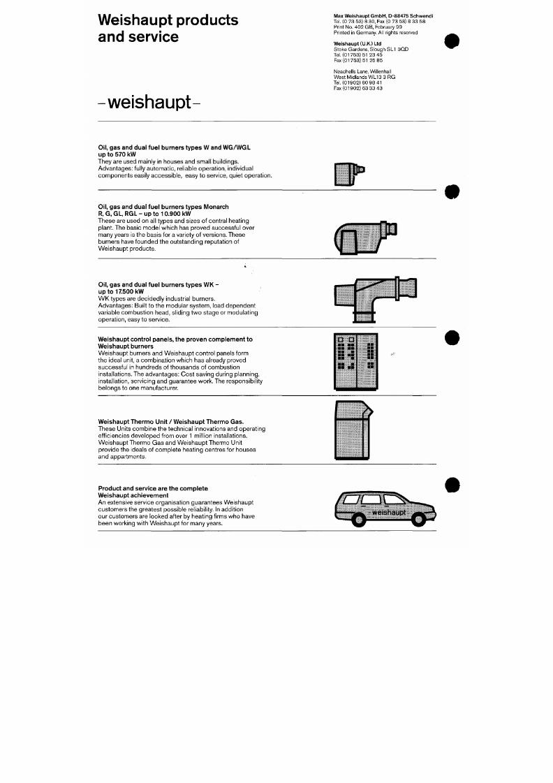
7/18/2019 M14 Thermal Fluid
http://slidepdf.com/reader/full/m14-thermal-fluid 409/486
Weishaupt products
and service
weishaupt-
Max Weishaupt GmbH, D-88475 Schwendi
Tel. (0 73 53) 8
30,
Fax (0 73 53) 8 33 58
Print No. 40 2 G B, February 99
Printed in Germany. All rights reserved
Weishaupt (U.K.) Ltd
Stoke Gardens, Slough SL1 3Q D
Tel. (01753)51 23 45
Fax (017 53) 51 25 85
Neachells Lane, Willenhall
West Midlands WL13 3 RG
Tel.(01902)60 98 41
Fax (01902) 63 33 43
Oil,
gas and dual fuel burners types W and WG /WG L
up to 570 kW
They are used mainly in houses and sm all buildings.
Advantages: fully automatic, reliable operation, individual
components easily accessible, easy to service, quiet operation.
D P '
Oil,
gas and dual fuel burners types Monarch
R, G, GL, RGL - up to 10 .90 0 kW
These are used on all types and sizes of central heating
plant. The basic model which has proved successful over
many years is the basis for a variety of versions. These
burners have founded the outstanding reputation of
Weishaupt products.
(nT
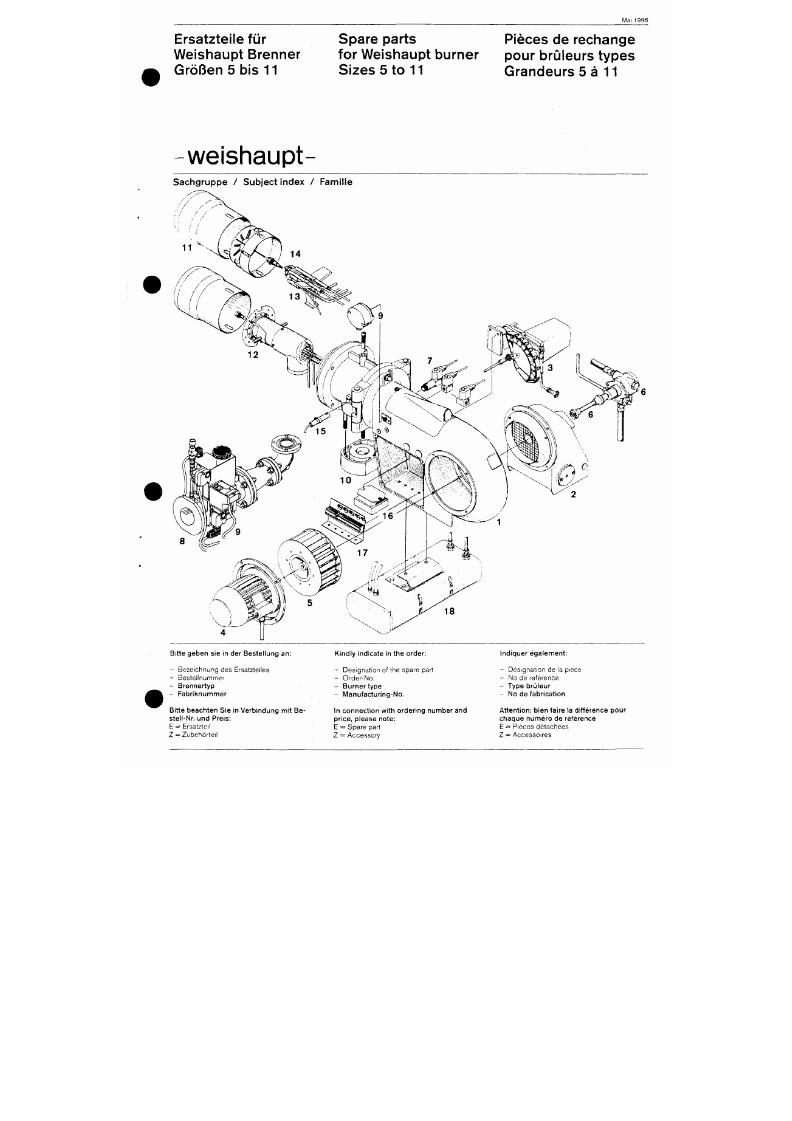
7/18/2019 M14 Thermal Fluid
http://slidepdf.com/reader/full/m14-thermal-fluid 410/486
M a i 1996
Ersatzteile für
Weishaupt Brenner
Größen 5 bis 11
Spare parts
for Weishaupt bu rner
Sizes 5 to 11
Pieces de rechange
pour brüleurs types
Grandeurs 5 å 11
weishaupt
Sach gruppe / Sub jec t index / Fami l le
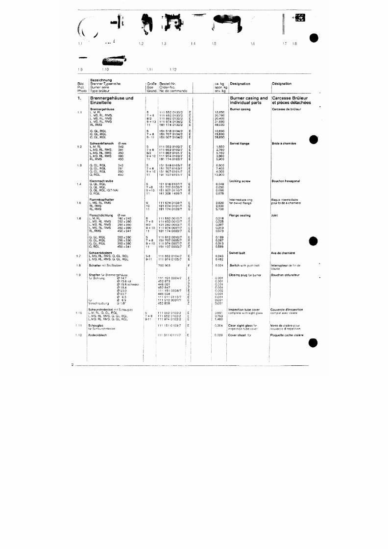
7/18/2019 M14 Thermal Fluid
http://slidepdf.com/reader/full/m14-thermal-fluid 411/486
^ J
• " f t S S S T "
1.1
1.4
1,5
1,7 1.,
1.10 1.1 i 1.12
Bi ld
P ie t .
P h o t o
B e z e i c h n u n g
B r e n n e r - T y p e n r e i h e
B u r n e r s e r i e
T y p e b r ü l e u r
i G r ö ß e ; B e s t e l l - N r .
S i z e j O r d e r - N o .
G r a n d , i N o d e c o m m a n d e
ca .
kg
appr . kg
env. kg
D e s i g n a t i o n
D e s i g n a t i o n
1.
1.2
1.3
1.4
Brennergehäuse und
Einzelteile
Brennergehäuse
L, M, RL
L,
MS, RL,
RMS,
L, MS, RL,
RMS
L, MS, RL, RMS
RL, RMS
G, GL , RGL
G,
GL ,
RGL
G, GL , RGL
Schwenkflansch
L,
M,
RL
L, MS, RL, RMS,
L,
M S,
RL , RMS
L,
MS, RL,
RMS
RL,
RMS
G. GL, RGL
G. GL , RGL
G, GL , RGL
G, RGL
0
mm
242
281
350
380
450
242
281
380
450
Klemmschraube
G. G L, RGL
7 - H 8
8/2
9 + 10
11
5
7 - ^ 8
5
7 - H 8
8/2
9 - H O
11
5
7 - H 8
9 -1 -10
11
5
1 1 1 5 5 2 0 1 0 3 / 2
1 1 1 6 5 2 0 1 0 3 / 2
1 1 1 8 6 2 0 1 0 2 / 2
1 1 1 9 7 4 0 1 0 4 / 2
1 8 1 1 7 4 0 1 0 2 / 2
1 5 1 5 1 8 0 1 0 4 / 2
1 5 1 7 0 7 0 1 0 4 / 2
1 5 1 9 0 7 0 1 0 4 / 2
1 1 1 5 5 2 0 1 0 2 / 7
1 1 1 6 5 2 0 1 0 2 / 7
1 1 1 8 6 2 0 1 0 1 / 7
1 1 1 9 7 4 0 1 0 2 / 7
1 8 1 1 7 4 0 1 0 2 / 7
1 5 1 5 1 8 0 1 0 5 / 7
1 5 1 7 0 7 0 1 0 3 / 7
1 5 1 9 0 7 0 1 0 1 / 7
1 9 1 1 0 7 0 1 0 1 / 7
1 5 1 5 1 8 0 1 0 7 / 7
1 3 , 8 5 0
2 0 , 7 8 0
2 0 . 4 0 0
3 1 , 8 8 0
4 8 , 0 0 0
1 0 , 6 0 0
1 5 , 6 0 0
2 8 , 8 0 0
1 ,650
2 ,780
5 , 1 6 0
3,880
5,900
6,600
7,400
4 ,000
1 3 , 9 0 0
0,048
Burner casing and
individual parts
Burner cas ing
Swive l f l ange
Carcasse Brüleur
et pieces détachées
Carcasse de brü leur
Bride a charniére
Lock ing screw Bouchon hexagona l
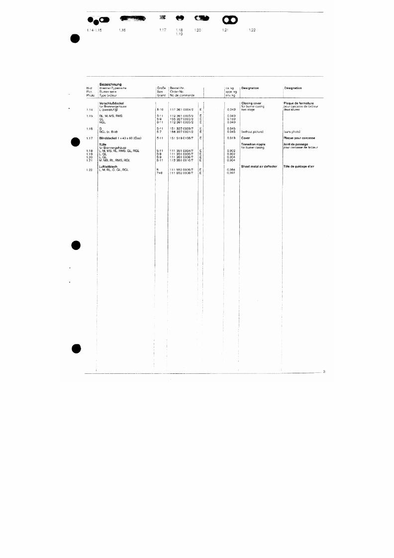
7/18/2019 M14 Thermal Fluid
http://slidepdf.com/reader/full/m14-thermal-fluid 412/486
^9 %JStf
OD
1 .M-1 .15 1.16
1.17
l . l i 1 .20 1.21 1.22
I B e z e i c h n u n g
Bt ld I Brenne r-Typenre ihe
Pict . i Burne r sene
Photo Type brü ieur
: Größ e I Bes te l l -Nr.
i S i ze I Orde r -No .
I Grand , j No de comm ande
j ca. kg
I appr. kg
I env. kg
Des igna t ion
; Designation
1.14
1.15
1.16
1.17
1.18
1.19
1.20
1.21
1.22
Versch lußdecke l
f ü r B renne rgehäuse
L (zweistu f ig)
RL , M . M S, RM S
G L
R G L
G
RGL (o. Bi ld)
Bl inddecke l 1 x 40 x 6 0 (Gas)
Tülle
f ü r B renne rgehäuse
L, M , M S , R L , R M S , G L , R G L
L, GL
L, GL
M , M S , R L , R M S , R G L
Luft le i tblech
L , M , RL , G, GL , RGL
5-10
5-11
5-9
8-11
5 -11
5-7
5-11
5-11
5-9
5-9
5-11
5
7-^8
111 361 0004/2
112 361 0005/2
155 327 0002/2
112 361 0005/2
151 327 0009/7
1 5 6 3 2 7 0 0 0 1 / 2
1 5 1 5 1 8 0 1 0 8 / 7
1 1 1 3 5 1 0 0 0 4 / 7
1 1 1 3 5 1 0 0 0 5 / 7
111 351 0006/7
112 351 0010/7
111 552 0009/7
111 652 0008/7
0 .040
0 .040
0 , 1 0 0
0 ,040
0 ,045
0 ,045
0 ,019
0 ,002
0 ,002
0 ,004
0 ,004
0 ,084
0 ,097
Closing cover
for burner casing
two stage
(wi thout p icture)
Cover
Transit ion nipple
for burner casing
Shee t meta l a i r de f lec tor
< P laque de fe rm eture
{pour carcasse de brü ieur
deux al lures
(sans photo)
Plaque pour ca rcasse
Jo in t de passage
pour carcasse de brü ieur
Töle de guidage d'air
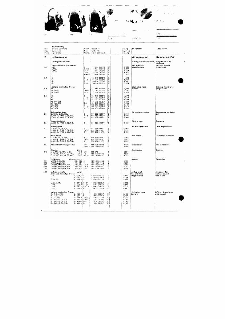
7/18/2019 M14 Thermal Fluid
http://slidepdf.com/reader/full/m14-thermal-fluid 413/486
% /
2.13-2,14
2,10
2,15
2,16
Bi ld
Piet,
Pho to
'
B e z e i c h n u n g
• Brenner-Typenre ihe
Burner ser ie
i Type brü ieur
1 Größe
{ Size
1 Grand ,
1 Beste l l -Nr ,
1 O r d e r - N o ,
j No de c omm ande
1
ca , kg
appf- 1*9
[ env, kg
Des igna t ion Des igna t ion
2.
2,1
2,2
2,3
2.4
Luftregelung
L u f t r e g l e r k o m p l e t t
1 zwe i - und dre is tu f ige Brenner
L, M
L, MS,
L. MS,
L
L
G
G
G L
G L
gle i tend-zwe is tu f ige Brenner
RL
RL, RMS
RL, RMS
G
G
G
G, Ausf, ZMI
G, Ausf, ZMI
GL, RGL
G L . R G L
GL, RGL
1
1
i
i
5
7-f8/2
9-t-IO
7T-fST
9T-H0T
5
7 - ( -8
5
7-1-8
5
7-H8/2
9-11
5
7-1-8
9-11
5
7-8
5
7-1-8
9-11
1 1 1 5 6 4 0 4 0 1 / 0
1 1 1 7 6 4 0 4 0 1 / 0
1 1
1 9 6 4 0 4 0 2 / 0
1 1 1 7 9 4 0 4 0 2 / 0
1 1 1 9 9 4 0 4 0 1 / 0
1 5 1 5 1 8 0 2 0 2 / 0
1 5 1 7 1 6 0 2 0 2 / 0
1 5 5 5 1 8 0 2 0 1 / 0
1 5 5 7 1 6 0 2 0 2 / 0
1 1 1 5 8 2 0 2 0 2 / 0
1 1 1 7 8 2 0 2 0 3 / 0
1 1 1 9 7 4 0 2 0 2 / 0
1 5 1 5 1 8 0 2 0 3 / 0
1 5 1 7 0 7 0 2 0 1 / 0
1 5 1 9 0 7 0 2 0 1 / 0
1 5 1 5 1 8 0 2 0 4 / 0
1 5 1 7 0 7 0 2 0 3 / 0
1 5 5 5 1 8 0 2 0 2 / 0
1 5 5 7 0 7 0 2 0 1 / 0
1 5 6 9 0 7 0 2 0 1 / 0
E
1
E
E
E
E
E
E
E
E
E
E
E
E
E
E
E
E
5 ,480
6 ,317
9 , 6 3 4
6 ,402
1 1 , 5 0 0
4 , 5 1 0
5 , 0 0 0
4 , 5 6 0
5 , 2 6 4
4 ,380
5 ,141
8 ,420
4 ,578
4 , 6 5 0
8 ,239
4 ,500
6 ,500
5 ,190
5 .010
8 ,226
Air regulation
A i r r e g u l a t i o n c o m p l e t e ,
two and th ree
s tage burners
sl iding two stage
burners
[Regulation d'air
[ R e g u l a t i o n d ' a i r
i comple te
brCileurs deux et
trols al lures
brüleurs deux al lures
progress ives
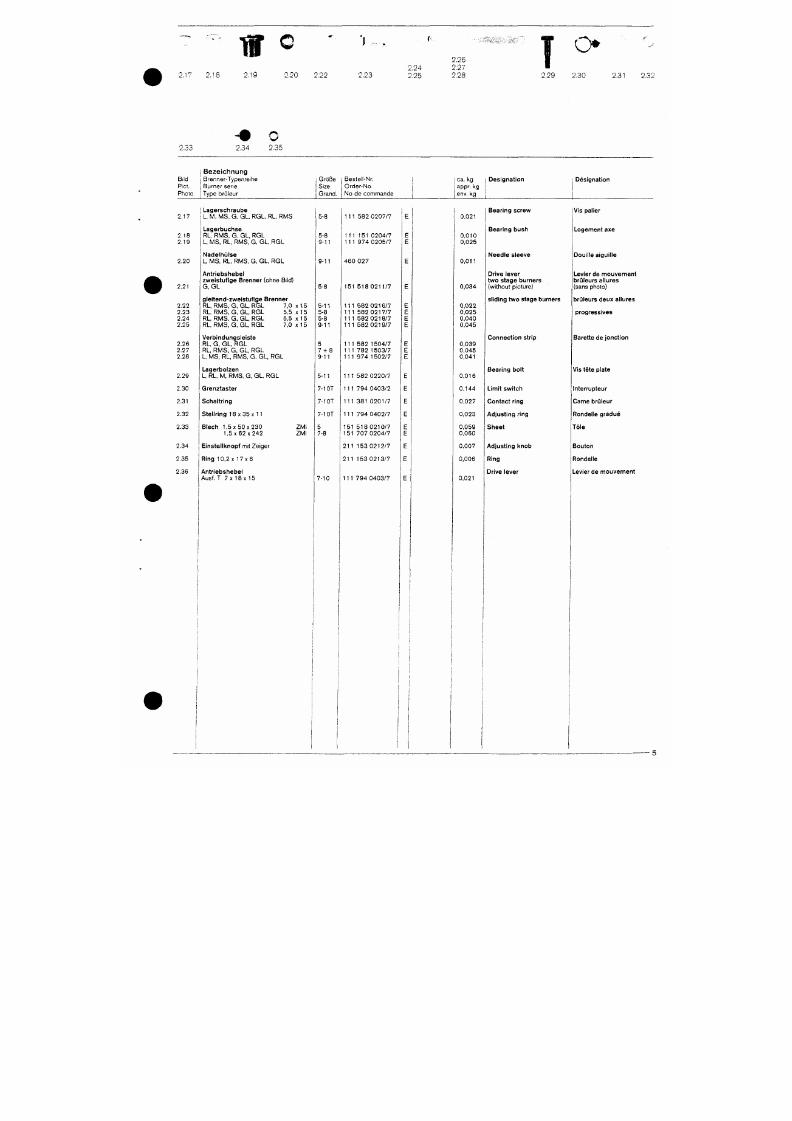
7/18/2019 M14 Thermal Fluid
http://slidepdf.com/reader/full/m14-thermal-fluid 414/486
2.17 2.18
t f ®
2.19
2.20 2.22 2.23
2.24
2,25
2.26
2.27
2.28
T
O»
2.29 2.30
2.31 2.32
2.33
2.34
O
2.35
Bi ld
Piet.
Photo
1 Bezeichnung
; B renne r -Typen re i he
i Burner sene
j Type bru leur
Größe
Size
Grand .
Beste l l -Nr .
O r d e r - N o .
N o d e c o m m a n d e
,
ca. kg
appr. kg
env. kg
Des igna t ion Des igna t ion
2.17
2.18
2.19
2.20
2.21
2.22
2.23
2.24
2.25
2.26
2.27
2.28
2.29
Lagerschraube
L, M,
M S, G, GL, RGL, RL, RMS
Lagerbuchse
RL. R MS, G, GL, RGL
L,
MS, RL, RMS, G, GL, RGL
Nadelhülse
L, MS, RL, RMS, G, GL, RGL
Antriebshebel
zweistufige Brenner (ohne Bild)
G, GL
gleitend-zweistufige Brenner
RL, RM S, G GL, RGL 7,0 x 15
RL, RMS,
G
GL,
RGL 5,5 x 15
RL, RMS, G GL, RGL 5,5 x15
RL, RM S, G GL, RGL 7,0 x 15
Verbindungsleiste
RL, G, GL, RGL
RL, RMS , G, GL, RGL
L, MS ,
RL, RMS, G,
G L,
RGL
Lagerbolzen
L,
RL, M, RMS, G, GL, RGL
5-8
5-8
9-11
9-11
5-8
5-11
5-8
5-8
9-11
5
7-H8
9-11
5-11
111 582 0207/7
111 151 0204/7
111 97 4 0205/7
460 027
151 518 0211/7
111 582 0216/7
111 582 0217/7
111 582 0218/7
111 582 0219/7
111 582 1504/7
111 782 1503/7
111 97 4 1502/7
111 582 0220/7
0 ,021
0 , 0 1 0
0,025
0 ,011
0,034
0,022
0,025
0,040
0,045
0,039
0,045
0 ,041
0 ,016
Bear ing screw
Bear ing bush
Need le s leeve
Drive lever
two s tage burners
(wi thout p icture)
sl iding two stage b
Connec t ion s t r ip
Bear ing bo l t
Vis paller
Logement axe
Douille aiguille
Levier de mouvement
brüleurs a llures
(sans photo)
brüleurs deux allures
progressives
Barette de jonction
Vis tete plate
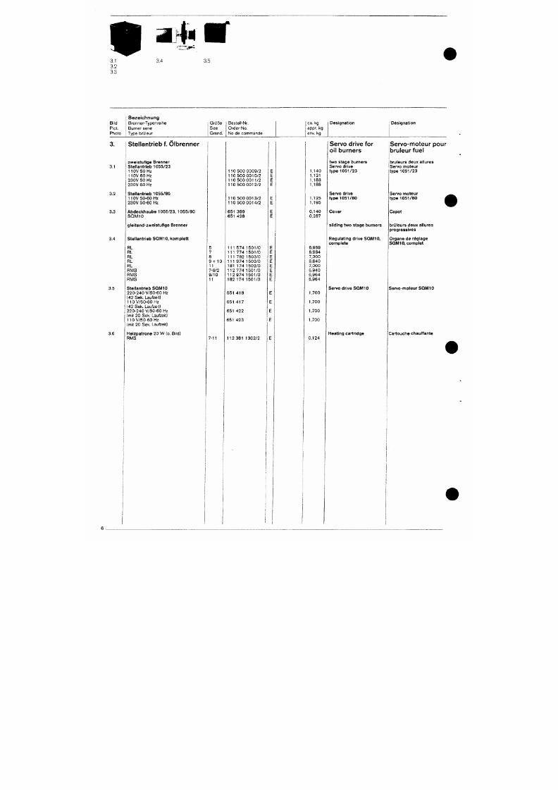
7/18/2019 M14 Thermal Fluid
http://slidepdf.com/reader/full/m14-thermal-fluid 415/486
3,4 3.5
Bild
Piet.
Photo
Bezeichnung
Brenner-Typenreihe
Burner serie
Type brüleur
Größe
Size
Grand.
Besteil-Nr.
Order-No.
No de commande
ca.
kg
appr. kg
env. kg
Designation Designation
3.1
3.2
3.3
3.4
Stellantrieb f. Olbrenner
zweistufige Brenner
Stellantrieb 105 5/23
110V 50 Hz
110V 60 Hz
230V 50 Hz
230V 60 Hz
Stellantrieb 105 5 /80
110V 50-60 Hz
230V 50-60 Hz
Abdeckhaube 1055/23, 1055/80
S QM10
gleitend-zweistufige Brenner
Stellantrieb SQM 10, komplett
RL
RL
RL
RL
RL
5
7
8
9-HO
11
110 500 0009/2
110 500 0010/2
110 500 0011/2
110 500 0012/2
110 500 0013/2
110 500 0014/2
651 399
651 428
111 5 74 1501/0
111 774 1501/0
111 782 1503/0
111 9 74 1503/0
181 174 1502/0
1,140
1,131
1,183
1,185
1,125
1,195
0,140
0,267
6,969
6,984
7,300
6,840
7,000
Servo drive for
oi l burners
two stage burners
Servo drive
type 1051/23
Servo drive
type 1051/80
Cover
sliding two stage burners
Regulating drive SQM10,
complete
Servo-moteur pour
bruleur fuel
bruleurs deux allures
Servo moteur
type 105 1/23
Servo moteur
type 105 1/80
Capot
bruleurs deux allures
progressives
Organe de réglage
SQM10, complet
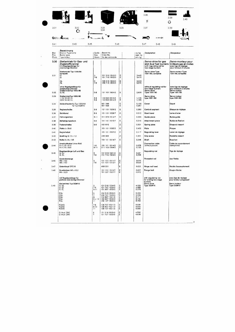
7/18/2019 M14 Thermal Fluid
http://slidepdf.com/reader/full/m14-thermal-fluid 416/486
3.31
^ » ^ - « . s «
3.41
3.32
3.33
3.34
3.35
3.36
3.37
3.38
O
3.39
3.40
3.43
^ * - .
3.45
X
3.46
3.47 3.48
i4.
3.49
Bi id
Piet .
Pho to
3.30
3 .31
3 .32
3 .33
3 .34
3 .35
: B e z e i c h n u n g
1 B renne r -Typen re i t ie
i Burner sene
I Type brü leur
Stellantrieb für Gas- und
Zweistoffbrenner
mit Rege lges tänge fü r
zwe is tu f ige Brenner
S t e l l a n t r i e b T y p 1 0 5 5 / 8 0
komple t t
G
G
G L
G L
ohne Rege lges tänge fü r
zwe is tu f ige Brenner
S t e l la n t r ie b T y p 1 0 5 5 / 8 0
G, GL
S t e l l a n t r i e b T y p 1 0 5 5 / 8 0
110V 50 -60 Hz
2 3 0 V 5 0 - 6 0 H z
A b d e c k h a u b e f ü r Typ 1055 /80
f ü r T y p S Q M I O
Regle rsche ibe
1 Größe
Size
Grand .
5
7-8
5
7-8
5-8
5-8
5-8
5-8
5-8
Beste l l -Nr.
O r d e r - N o .
N o d e c o m m a n d e
1 5 1 5 1 6 1 5 0 2 / 0
1 5 1 7 1 6 1 5 0 2 / 0
1 5 5 5 1 6 1 5 0 2 / 0
1 5 5 7 1 6 1 5 0 2 / 0
1 5 1 1 0 1 1 5 0 4 / 2
1 1 0 5 0 0 0 0 1 3 / 2
1 1 0 5 0 0 0 0 1 4 / 2
6 5 1 3 9 9
6 5 1 4 2 8
1 5 1 1 0 1 1 5 0 6 / 2
151 101 1528 /7
E
E
E
E
E
E
E
E
E
E
E
ca .
kg
appr. kg
env. kg
3,445
3,470
3,343
3,370
2 ,926
1,125
1,195
0 ,139
0,267
0,390
0 ,012
i Des igna t ion
Servo-drive for gas
and dual fuel burners
with regulat ing rod for
two s tage burners
Servo dr ive Type
1 0 5 1 / 8 0 , c o m p le t e
without regulat ing rod for
two s tage burners
Servo dr ive
T y p e 1 0 5 1 / 8 0
Servo dr ive
t y p e 1 0 5 1 / 8 0
Cover
Cont ro l segment
Stee l band
Designation
Servo-monteur pour
brüleurs gaz et m ixtes
avec t ige de réglage
pour brüleurs 2 al lures
Servo-moteur Type
1 0 5 1 / 8 0 , c o m p l e t e
sans t Ige de réglage
pour brüleurs 2 al lures
Servo moteur
T y p e 1 0 5 1 / 8 0
Servo moteur
t y p e 1 0 5 1 / 8 0
Capot
Disque de rég lage
Lame d'acier
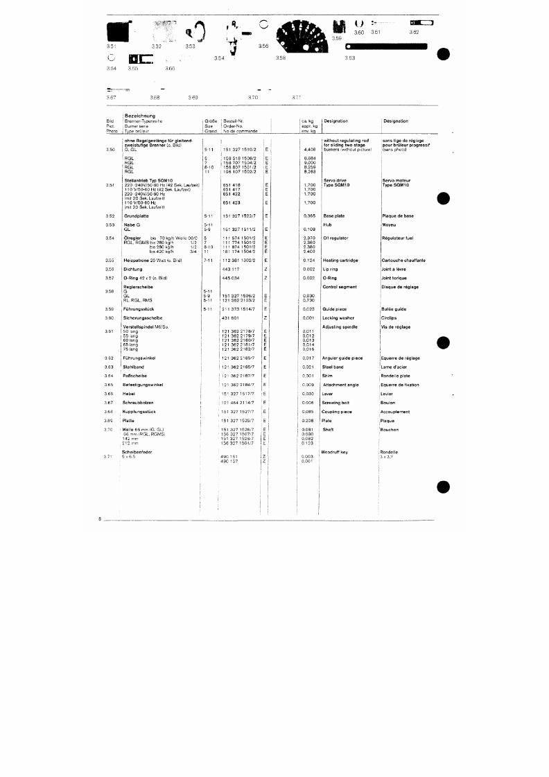
7/18/2019 M14 Thermal Fluid
http://slidepdf.com/reader/full/m14-thermal-fluid 417/486
3,51
3.64 3.65
3.52
3.66
t
3.53
3.54
,1r
' N W /
3.56
3.58
3.63
3.67 3.68 ).69
3.70
Bi ld
Piet.
Pho to
3.50
3.51
3.52
3.53
3.54
3.55
i B e z e i c h n u n g
^ B renne r -Typen re i he
Burner ser ie
j Type brü leur
ohne Rege lges tänge fü r g le i tend
zwe is tu f ige Brenner (o , Bi ld)
G . G L
i RGL
R G L
'' R G L
R G L
Ste l lan t r ieb Typ SQIM10
220 -240V/50 -60 Hz (42 Sek. Lau fze i t )
110 V /50 -60 Hz (42 Sek. Lau fze i t )
2 2 0 • 2 4 0 V / 5 0 - 6 0 H z
(mi t 20 Sek. Laufze i t )
1 1 0 V / 5 0 - 6 0 H z
(mit 20 Sek. Laufzeit)
Grundpla t te
N a b e G
G L
Ö l r e g l e r b i s 70 kg /h We l l e 00 / 0
R G L ,
RG M S b i s 280 kg /h 1 /2
b is 280 kg/h 1/2
b i s 420 kg /h 3 /4
H e i z p a t r o n e 20 Watt (o . Bi ld)
G r ö 6 e
Size
Grand .
5-11
5
7
8 -10
11
5 -11
5-11
5-9
5
7
8 -10
11
7-11
; Beste l l -Nr.
1
O r d e r - N o .
, N o d e c o m m a n d e
: 151 327 1510 /2
: 1 5 6 5 1 8 1 5 0 8 / 2
1 1 5 6 7 0 7 1 5 0 4 / 2
' 1 5 6 8 0 7 1 5 0 1 / 2
1 9 6 1 0 7 1 5 0 2 / 2
6 5 1 4 1 8
6 5 1 4 1 7
6 5 1 4 2 2
6 5 1 4 2 3
1 5 1 3 2 7 1 5 2 2 / 7
1 5 1 3 2 7 1 5 1 1 / 2
1 1 1 5 7 4 1 5 0 1 / 2
1 1 1 7 7 4 1 5 0 1 / 2
1 1 1 8 7 4 1 5 0 1 / 2
1 8 1 1 7 4 1 5 0 4 / 2
1 1 2 3 8 1 1 3 0 2 / 2
1
ca. kg
i appr- kg
1 j env. kg
E
E
E
E
E
E
E
E
E
E
E
E
E
E
E
E
4 , 4 0 8
8,884
9,000
8,259
8,263
1 ,700
1 ,700
1 ,700
1 ,700
0,365
0 , 1 0 8
2 , 3 7 0
2 , 3 6 0
2 , 3 8 0
2 , 4 0 0
0 , 1 2 4
Des igna t ion
wi thout regu la t ing rod
for sl iding two stage
burners (wi thout p icture)
Servo drive
T y p e S Q M I O
Base p la te
Hub
Oil regulator
Hea t ing ca r t r idge
1
Des igna t ion
isans t ige de réglage
I pour brü leur progressif
j
(sans photo)
Servo moteur
T y p e S Q M I O
(
Plaque de base
M o y e u
Régula teur fue l
Car touche chauf fan te
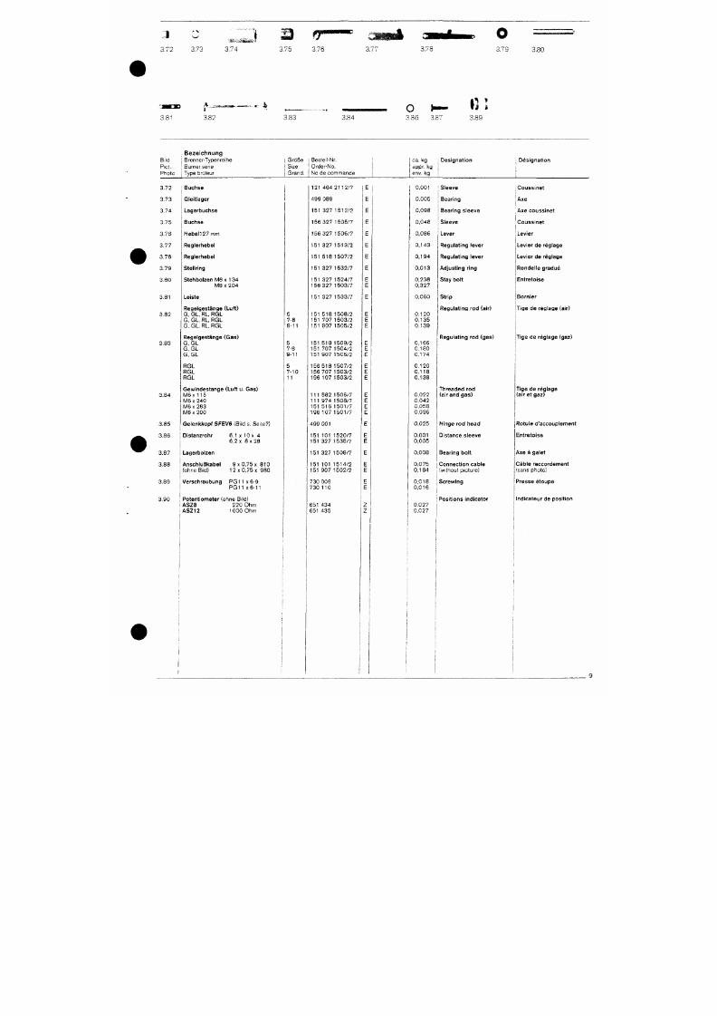
7/18/2019 M14 Thermal Fluid
http://slidepdf.com/reader/full/m14-thermal-fluid 418/486
3.72 3.73
3.74
f m m
;.75 3.76 3.77
3.78
3.79
3.80
3.81
A
i •
3.82
3.83
3.S4
H- fil
3.36 3.S7
3.89
Bild
PiCt.
Pho to
i B e z e i c h n u n g
1 Brenner-Typenre ihe
Burner ser ie
1 Type brüleur
Größe
Size
Grand .
Beste l l -Nr.
Orde r -No .
N o d e c o m m a n d e
c a . k g
appr. kg
env. kg
i Des igna t ion
; Des igna t ion
3 .72
3 .73
3 .74
3 .75
3 .76
3 .77
3 . 7 8
3 .79
3 .80
3.81
3 .82
3 .83
Buchse
Gleit lager
Lagerbuchse
Buchse
H e b e l 2 7 mm
Regle rhebe l
Reg le rhebe l
Stel lr ing
Stehbo lzen M8 x 1 3 4
M 8 X 2 0 4
Leiste
Rege lges tänge (Lu f t )
G, GL, RL, R G L
G, GL. RL, R G L
G, GL, RL, R G L
Rege lges tänge (Gas )
G GL
5
7-8
9 -11
5
121 464
4 9 9 0 8 9
151 327
156 327
156 327
151 32?
151 518
151 327
151 327
156 327
2 1 1 2 / 7
1 5 1 2 / 2
1 5 0 5 / ?
1506/?
1 5 1 3 / 2
1 5 0 7 / 2
1 5 3 2 / 7
1 5 2 4 / 7
1 5 0 3 / 7
1 5 1 3 2 7 1 5 3 3 / 7
1 5 1 5 1 8 1 5 0 8 / 2
1 5 1 7 0 ? 1 5 0 3 / 2
1 5 1 9 0 ? 1 5 0 5 / 2
151 518 1 509 /2
0 , 0 0 1
0.005
0,098
0,048
0,086
0 , 1 4 3
0 , 1 9 4
0 , 0 1 3
0,238
0,327
0,060
0 , 1 2 0
0 , 1 3 5
0 , 1 3 9
0 , 1 6 6
Sleeve
\ Bear ing
Bear ing s leeve
Sleeve
Lever
Regulat ing lever
Regulat ing lever
Adjusting ring
Stay bolt
Strip
Regulat ing rod (air)
Regulat ing rod (gas
Couss ine t
'Axe
I
I Axe couss ine t
Couss ine t
j
Levier
Levier de réglage
Levier de réglage
Ronde l le g radué
Ent re to ise
Born ie r
Tige de réglage (air)
T ige de rég lage (gaz)
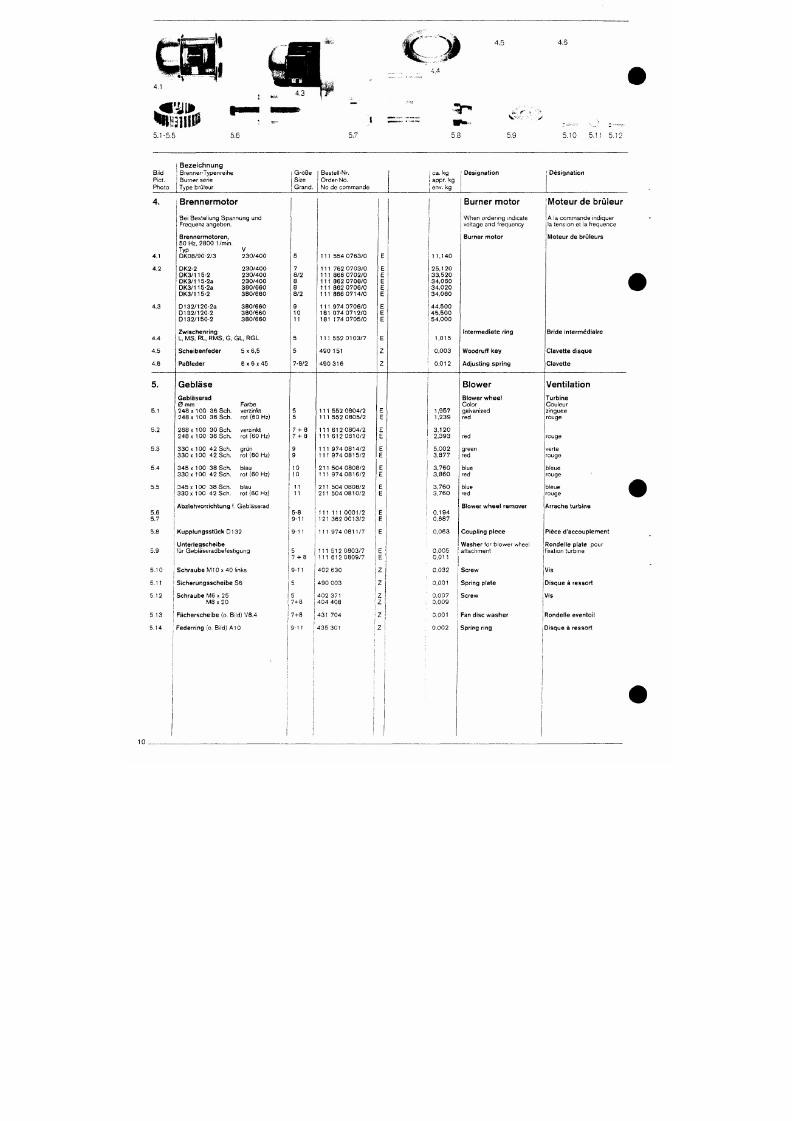
7/18/2019 M14 Thermal Fluid
http://slidepdf.com/reader/full/m14-thermal-fluid 419/486
5.1-5.5
5.6
4.5
4.4
• •^T*
5.8
4.6
5.9
5.10 5.11 5.12
Bild
Pict.
Photo
B e z e i c h n u n g
1 Brenner-Typenreihe
j Burner serie
i
Type brüleur
Größe
Size
Grand.
Bestell-Nr.
Order-No.
No de commande
; ca. kg
i appr. kg
i env. kg
Designation Designation
4.1
4.2
4.3
4.4
4.5
4.6
Brennermotor
Be i Beste l l ung Spannung und
Frequenz angeben .
B r e n n e r m o t o r e n ,
50 Hz, 2800 1/min.
Typ V
D K 0 8 / 9 0 - 2 / 3 2 3 0 / 4 0 0
D K 2 - 2
D K 3 / 1 1 5 - 2
D K 3 / 1 1 5 - 2 a
D K 3 / 1 1 5 - 2 a
D K 3 / 1 1 5 - 2
D 1 3 2 / 1 2 0 - 2 a
D I 3 2 / 1 2 0 - 2
D I 3 2 / 1 5 0 - 2
2 3 0 / 4 0 0
2 3 0 / 4 0 0
2 3 0 / 4 0 0
3 8 0 / 6 6 0
3 8 0 / 6 6 0
3 8 0 / 6 6 0
3 8 0 / 6 6 0
3 8 0 / 6 6 0
Zwischenr ing
L, MS, RL, RMS, G, GL, R G L
Sche ibenfeder
P a ß f e d e r
5 x 6 , 5
6 X 6 X 4 5
7
8 /2
8
8
8 /2
9
1 0
11
5
5
7 -8 /2
1 1 1 5 5 4 0 7 6 3 / 0
1 1 1 7 6 2 0 7 0 3 / 0
1 1 1 8 6 6 0 7 0 2 / 0
1 1 1 8 6 2 0 7 0 8 / 0
1 1 1 8 6 2 0 7 0 6 / 0
1 1 1 8 6 6 0 7 1 4 / 0
1 1 1 9 7 4 0 7 0 6 / 0
1 8 1 0 7 4 0 7 1 2 / 0
1 8 1 1 7 4 0 7 0 5 / 0
1 1 1 5 5 2 0 1 0 3 / 7
490 151
4 9 0 3 1 6
1 1 . 1 4 0
2 5 , 1 2 0
3 3 , 5 2 0
3 4 . 0 6 0
3 4 , 0 2 0
3 4 , 0 6 0
4 4 , 5 0 0
4 5 , 5 0 0
5 4 ,0 0 0
1,015
0,003
0 , 0 1 2
Burner motor
When o rde r i ng i nd i ca te
vol tage and f requency
Burner motor
In te rmedia te r ing
Woodruff key
Adjus t ing spr ing
Moteur de brüleur
A l a commande i nd i que r
la tension et la f requence
Moteur de brOleurs
Br ide in te rmédia i re
Clave t te d isque
Clave t te
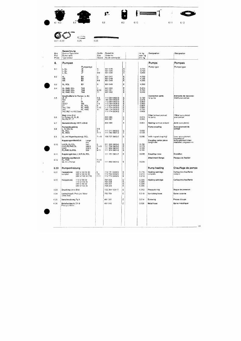
7/18/2019 M14 Thermal Fluid
http://slidepdf.com/reader/full/m14-thermal-fluid 420/486
w
4k
6.1-6.3 GAwK fKm
6.8
Ü
6.9
6.10
6.11
6.12
6.21.-6.22
6.25 6.26
Bi ld
Piet.
Pho to
Bezeichnung
Brenner-Typenre ihe
Burner ser ie
Type brü ieur
G r ö B e
Size
Grand .
Beste l l -Nr.
Orde r -No .
No de c o m m a n d e
ca . k g
app r . kg
env. kg
Des igna t ion
Des igna t ion
6.1
6.2
6.3
6.4
6.5
P u m p e n
L G L
L, G L
L. GL
M ,
M S
M S
RL, RGL
RL, RMS, RGL
RL, RMS, RGL
RL, RMS, RGL
P u m p e n t y p
J6
J6
J7
E 4
E 6
E 7
E 7
T A 2
T A 3
T A 4
AnschluBtei le f ü r P u m p e : (o. B.)
J6 , J7 L
T A 2 L
E4 M
E 6 / E 7 M S
E7 RL , RG L
T A 2 ,
TA3 RL , RM S
TA4 RL , RM S
TA2 (RL7 m it K3 Düse )
Sieb (ohne Bild)
5
7
8-9
5
7
8-9
7
8-10
11
5-9
10T
5
7-9
5
7-10
11
601 005
601 005
601 006
601 047
601 048
601 049
601 049
601 050
601 051
601 052
111 564 0602/2
181 094 0603/2
112 564 0602/2
112 764 0605/2
111 574 0602/2
111 774 0603/2
181 174 0602/2
111 774 0604/2
3 720
3 720
3 900
4 050
4,165
4 290
4 290
5,470
5,760
6,040
0 ,190
0,275
0,600
0,560
0,605
0,590
0,720
0,608
P u m p s
P u m p t y p e
Connec t ion par ts
for pump
Filter (wi thout p icture)
P o m p e s
P o m p e t y p e
Elements de raccorde -
m e n t pou r pompe
Filtre (sans photo)
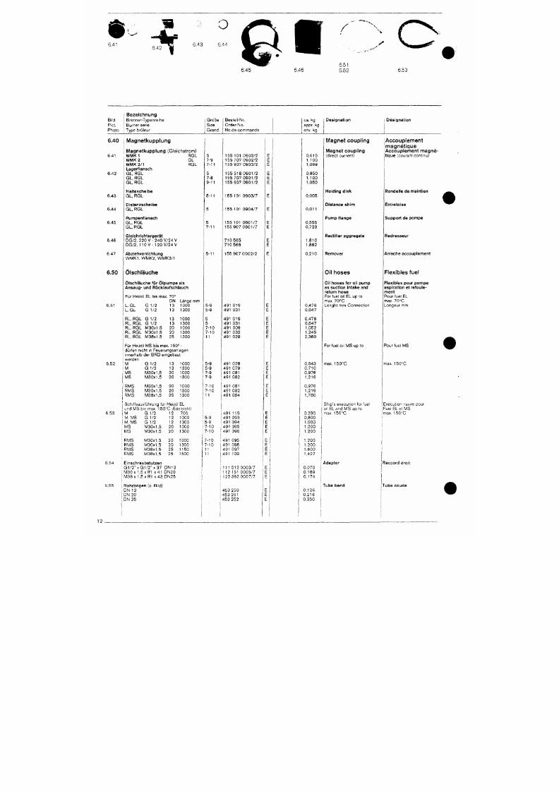
7/18/2019 M14 Thermal Fluid
http://slidepdf.com/reader/full/m14-thermal-fluid 421/486
t f e
6.41
O
6.43 6.44
6.45
6.46
/
6.51
6.52
^ \
%
X
V „. .ar
6.53
Bi ld
Piet.
Pho to
6.40
6 ,41
6 .42
6 .43
6 .44
6 .45
6 .46
6 .47
1 B e z e i c h n u n g
1 Brenner-Typenre ihe
j Burner ser ie
Type bru leur
M a g n e t k u p p l u n g
M a g n e t k u p p l u n g ( G l e i c h s t r o m )
W M K 1 R G L
W M K 2 G L
W M K 2 / 1 R G L
Lagerf lansch
G L,
RGL
G L, R G L
G L, R G L
Hal tesche lbe
G L, R G L
Dis tanzsche ibe
GL ,
R G L
Pumpenf lansch
G L, R G L
G L,
R G L
Gle ichr ich te rgerä t
D G / 2 , 2 2 0 V - 2 4 0 V /24 V
D G / 2 ,
110 V - 1 2 0 V / 2 4 V
Abziehvorr ich tung
W M K 1 , W M K 2 , W M K 2 / 1
Größe
Size
Gr and.
5
7-9
7-11
5
7-8
9 -11
5-11
5
5
7-11
5-11
Beste i l -Nr.
Orde r -No .
N o d e c o m m a n d e
1 5 5 1 0 1 0 9 0 3 / 2
1 5 5 7 0 7 0 9 0 2 / 2
1 5 5 9 0 7 0 9 0 3 / 2
1 5 5 5 1 8 0 9 0 1 / 2
1 5 5 7 0 7 0 9 0 1 / 2
1 5 5 9 0 7 0 9 0 1 / 2
1 5 5 1 0 1 0 9 0 3 / 7
1 5 5 1 0 1 0 9 0 4 / 7
1 5 5 1 0 1 0 6 0 1 / 7
1 5 5 9 0 7 0 6 0 1 / 7
710 565
710 566
1 5 5 9 0 7 0 0 0 2 / 2
E
E
E
E
E
E
E
E
E
E
E
E
E
ca . kg
appr. kg
env. kg
0 ,615
1,100
1,099
0,850
1,100
1,050
0,005
0 ,011
0,555
0,723
1,810
1,862
0 ,210
Des igna t ion
M a g n e t c o u p l i n g
l\^agnet
coupling
(d i rect current)
Hold ing d isk
Dis tance sh im
P u m p f l a n g e
Rec t i f i e r aggrega te
Remover
Des igna t ion
l A c c o u p l e m e n t
m a g n é t l q u e
l A c c o u p l e m e n t m a g n é
t lque (courant cont inu)
Ronde l le de ma in t ien
Ent re to ise
Suppor t de pompe
Redresseur
Arrache accoup lement
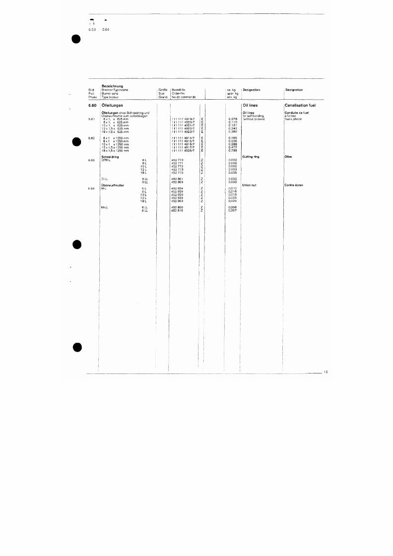
7/18/2019 M14 Thermal Fluid
http://slidepdf.com/reader/full/m14-thermal-fluid 422/486
6.63
6.64
; Bezeichnung
Bi ld ] Brenner-T ypenre ihe
Piet . I Burner ser ie
Pho to j Type br i j ieur
I Größe
I Size
Beste l l -Nr.
Orde r -No .
I Gran d . No de comm ande
I ca. kg
I appr- l^g
env. kg
I Des igna t ion
: Des igna t ion
6.60 Ölleitungen
6.61
6 .62
6 .63
6 .64
Öl le i tungen ohne Schne id r i ng und
Übe rwu r fmu t te r zum se lbs tb i egen
6 x 1 ,
X 625 mm
8x 1
l O x 1
12x 1
18x 1
X 625 mm
X 625 mm
5
X
625 mm
5x 625 mm
6 x 1
X
1 2 5 0 m m
8 x 1 X 1 250 mm
1 0 x 1 X 1 2 5 0 m m
12 X
1,5x1250
m m
18
X
1,5
X
1 2 5 0 m m
Schne idr ing
DPR-L
D-LL
IJberwurfmutter
M-L
6 L
8 L
10L
12L
18L
6LL
8LL
6 L
111 111 4919/7
111 111 4920/7
111 111 4921/7
111 111 4922/7
111 111 4923/7
111 111 4914/7
111 111 4915/7
111 111 4916/7
111 111 4917/7
111 111 4925/7
452 770
452 771
452 772
452 773
452 775
452 801
452 809
452 834
E
E
E
E
E
E
E
E
E
E
Z
Z
Z
Z
Z
Z
Z
Z
0 . 0 7 8
0 , 1 1 0
0 , 1 3 1
0 , 2 4 2
0 , 3 8 0
0 , 1 6 5
0 , 2 2 6
0 , 2 8 8
0 , 4 7 7
0 , 7 3 9
0 , 0 0 2
0 , 0 0 2
0 , 0 0 2
0 , 0 0 3
0 . 0 0 5
0 , 0 0 2
0 . 0 0 3
0 , 0 1 0
Oil lines
Oil lines
for se l f bending
(wi thout p icture)
jCanalisation fuel
jCondu i te d e fuel
ja former
(sans photo)
Cutt ing ring
Union nut
Olive
Cent re éc ren
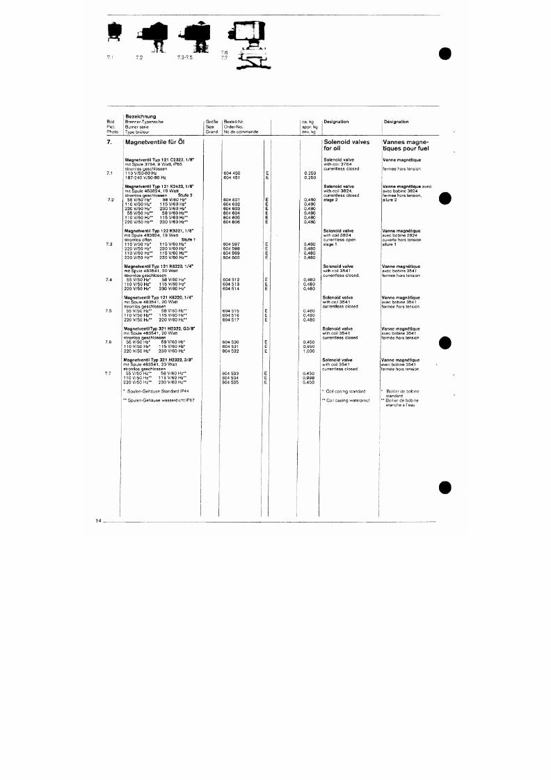
7/18/2019 M14 Thermal Fluid
http://slidepdf.com/reader/full/m14-thermal-fluid 423/486
f * * *^
7.1
B i l d
Piet .
Pho to
B e z e i c h n u n g
Brenne r -Typen re i he
Burner ser ie
Type bn j l eu r
i Größe
I Size
Grand .
Beste l l -Nr.
Orde r -No .
N o d e c o m m a n d e
ca. kg
appr, kg
env. kg
Des igna t ion
Des igna t ion
7.1
7.2
7.3
M agnetventi le für Öl
M a g n e t v e n t i l T y p 1 2 1 C 2 3 2 3 , 1 / 8 "
mi t Spu le 3764 , 9 Wa t t , IP65
s t r o m l o s g e s c h l o s s e n
1 1 0 V / 5 0 - 6 0 H Z
1 8 7 - 2 4 0 V / 5 0 - 6 0 H z
M a g n e t v e n t i l T y p 1 2 1 K 2 4 2 3 , 1 / 8 "
m i t S p u l e 4 8 3 8 2 4 , 1 9 W a t t
s t r o m lo s g e s c h l o s s e n Stufe 2
5 5 V / 5 0 Hz*
1 1 0
V / 5 0
Hz*
2 2 0 V / 5 0 Hz*
5 5 V / 5 0 H z * *
1 1 0 V / 5 0 H z "
2 2 0 V / 5 0 H z * *
5 8 V / 6 0 Hz*
1 1 5
V / 6 0
Hz*
2 3 0 V / 6 0 Hz*
5 8 V / 6 0 H z * *
11 5 V / 6 0 H z * *
2 3 0 V / 6 0 H z * *
M a g n e t v e n t i l T y p 1 2 2 K 9 3 2 1 , 1 / 8 "
m i t S p u l e 4 8 3 8 2 4 , 1 9 W a t t
s t romlos o f f en
110 V /50 Hz*
220 V /50 Hz*
110 V /50 Hz* *
2 2 0 V / 5 0 H z * *
Stufe 1
1 1 5 V / 6 0 Hz*
2 3 0 V / 6 0 Hz*
1 1 5 V / 6 0 H z * *
2 3 0 V / 6 0 H z * *
604 450
604 451
604 601
604
602
604 603
604 604
604 605
604 606
604 597
604 598
604 599
604 600
0,250
0,250
0,480
0,480
0,480
0,480
0,480
0,480
0,480
0,480
0,480
0,480
Solenoid vatves
for oil
Soleno id va lve
wi th co i l 3764
cu r ren t l ess c l osed
Soleno id va lve
wi th co i l 3 8 2 4 ,
cu r ren t l ess c l osed
stage 2
Soleno id va lve
wi th co i l 3824
cu r ren t l ess open
stage 1
Vannes magne-
t iques pour fuel
V a n n e m a g n é t i q u e
f e rmée ho rs t ens i on
V a n n e m a g n é t i q u e avec
avec bob ine 3824
fe rmée ho rs t ens i on ,
a l lure 2
Vanne nnagné t ique
avec bob ine 3824
ouverte hors tension
allure 1
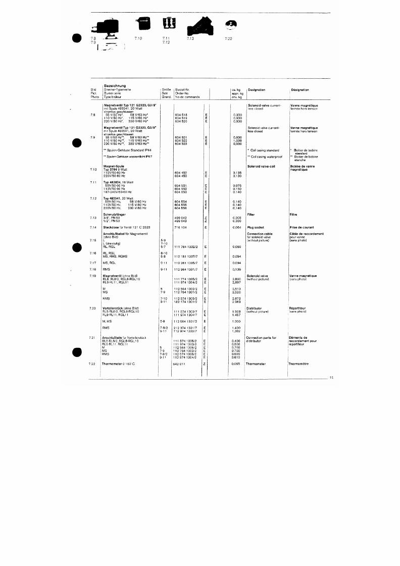
7/18/2019 M14 Thermal Fluid
http://slidepdf.com/reader/full/m14-thermal-fluid 424/486
7 .8 . - . £ _ - » . . 7 . 1 0 7 . 1 1 7 , 1 3
7 .9 ^ ^ 7 . 1 2
0 ^
7 . 2 2
Bi ld
Piet.
Photo
I B e z e i c h n u n g
Brenner-Typenre ihe
Burner ser ie
Type brü leur
G r ö 8 e
1 Size
j Grand .
Beste l l -Nr.
Orde r -No .
No de commande
ca .
k g
appr. kg
env. kg
Designation 1 Des igna t ion
1
1
7.8
7.9
7.10
7.11
Magnetvent i l Typ 121 G2320 , G3 /8 "
mit Spule 4 8 3 5 4 1 , 2 0 W a t t
s t romlos gesch lossen
55 V /50 Hz ' , 58 V / 60 Hz*
110 V /50 Hz* , 115 V /60 Hz*
220 V /50 Hz* , 230 V /6 0 Hz*
Magnetvent i l Typ 121 G2320 , G3 /8 "
mit Spule
4 8 3 5 4 1 ,
2 0 W a t t
s t romlos gesch lossen
55 V /50 Hz* * , 58 V / 60 Hz* *
110 V /50 Hz* * , 115 V / 60 Hz* *
2 2 0 V / 5 0 H z " , 2 3 0 V / 6 0 H z * *
* * Spu len -Gehäuse S tanda rd IP44
** Spulen-Gehäuse wasserd icht IP67
M a g n e t - S p u l e
Typ 3764 9 Wat t
11OV/50 -60 Hz
2 2 0 V / 5 0 - 6 0 H z
T y p 4 8 3 8 2 4 , 19 Wa t t
5 5 V / 5 0 - 6 0 H z
11 OV/50 -60 Hz
1 8 7 - 2 4 0 V / 5 0 - 6 0 H z
604 518
604 519
604 520
604 521
604 522
604 523
604 452
604 453
604 551
604 552
604 553
0,330
0,930
0,930
0,930
1,039
0,930
0 , 1 3 5
0 , 1 3 0
0,075
0 , 1 5 0
0 , 1 4 0
Solenoid valve cu r ren t -
less closed
So leno id va lve cu r ren t -
iess closed
* Co i l cas i ng s tanda rd
* * Co i l cas i ng w a te rp roo f
Solenoid valve coi l
Vanne magnét ique
fermée hors tension
Vanne magnét ique
fermée hors tension
* Boi t ier de bobine
standa rd
** Boi t ier de bobine
e tanche
Bobine de vanne
magnét ique
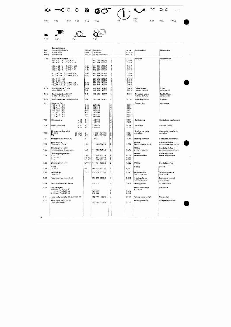
7/18/2019 M14 Thermal Fluid
http://slidepdf.com/reader/full/m14-thermal-fluid 425/486
m ^
~-T3C O
7,23 7.26
7.27
7.28
B ØO"
7.29 7.30
(D
,31
7.32
7.34 '.33 7.35 7.36
7.39 7.40
,0-
.41
S3
7.42
; B e z e i c h n u n g
Bi l d ; B renne r -Typen re i he
Piet . i Burne r ser ie
Photo ; Type br i j leur
Größe
Size
Grand .
Beste l l -Nr.
O r d e r - N o .
N o d e c o m m a n d e
ca .
kg
appr. kg
env. kg
Des igna t ion Des igna t ion
7 .23
7.24
7.25
7 .26
7 .27
i
E inschraubs tu tzen
j 6L LM 1 0x 1 x G 1 /8 " x 71
6 L L M l O x 1 x G 1 / 8 ' x 2 3
8 L L M 1 2 x 1 x G 1 / 8 " x 2 3 , 5
8 L L M 1 2 x 1 x G 1 / 8 " x 2 5
8 L L M 1 2 x 1 x G 1 / 8 " x 7 1
1 0 L L M 1 6 x 1 , 5 x G 1/4"x35
1 0 L L M 1 6 x 1 , 5 x G
1/4"x71,5
12 X G 1 /4 " X 4 2
1 2 X
G 3 / 8 "
X
4 6
1 2 L L M 1 8 x 1 . 5 x G 1 /4 " x 3 5
1 2 L L M 1 8 x 1 , 5 x G 3 / 8 "
X
36 ,5
B u n d s c h r a u b e G 1/8"
( o h n e B i l d ) G 1 / 4 "
G e w i n d e b u c h s e G 1 / 4 "
M 2 0 x 1 ,5 (ohne B i l d )
A u f n a h m e h ü l s e für Heizpatrone
Dicht r ing C U
10 ,0 X 14 X 1.5
13 ,5
X
17
X
1,5
1 3 ,5 x 2 5 x 2 , 0
1 6 , 0 x 2 0
X
1,5
5-11
7-11
7-10
5-11
9 -11
5 -10
9-11
5 -11
5-9
5-9
5-9
5-11
5-11
5-11
5-11
1 1 2 1 5 1 1 3 1 7 / 7
1 1 1 5 7 4 1 3 0 7 / 7
1 1 1 3 8 1 1 3 0 7 / 7
1 1 1 5 7 4 1 3 0 8 / 7
1 1 2 2 6 1 1 3 1 0 / 7
111 5 74 1301/7
111 9 74 1302/7
121 464 8502/7
121 464 8505/7
111 5 74 1302/7
111 9 74 1303/7
111 57 4 1304/7
112 564 1305/7
112 564 1307/7
112 564 1304/7
440 034
440 010
440 014
440 048
0,064
0 ,013
0 ,017
0 ,015
0,059
0,039
0,083
0,045
0,020
0,038
0,053
0,008
0,026
0,026
0 ,110
0 .001
0 ,001
0,006
0 ,001
Adapte r
Co l la r sc rew
(wi thout p icture)
T h r e a d e d s l e e v e
(w i t hou t p i c tu re )
Mount ing socke t
Copper r ing
Raccord droit
Ecrou
(sans photo)
Douil le f i letée
(sans photo)
Suppor t
Joint cuivre
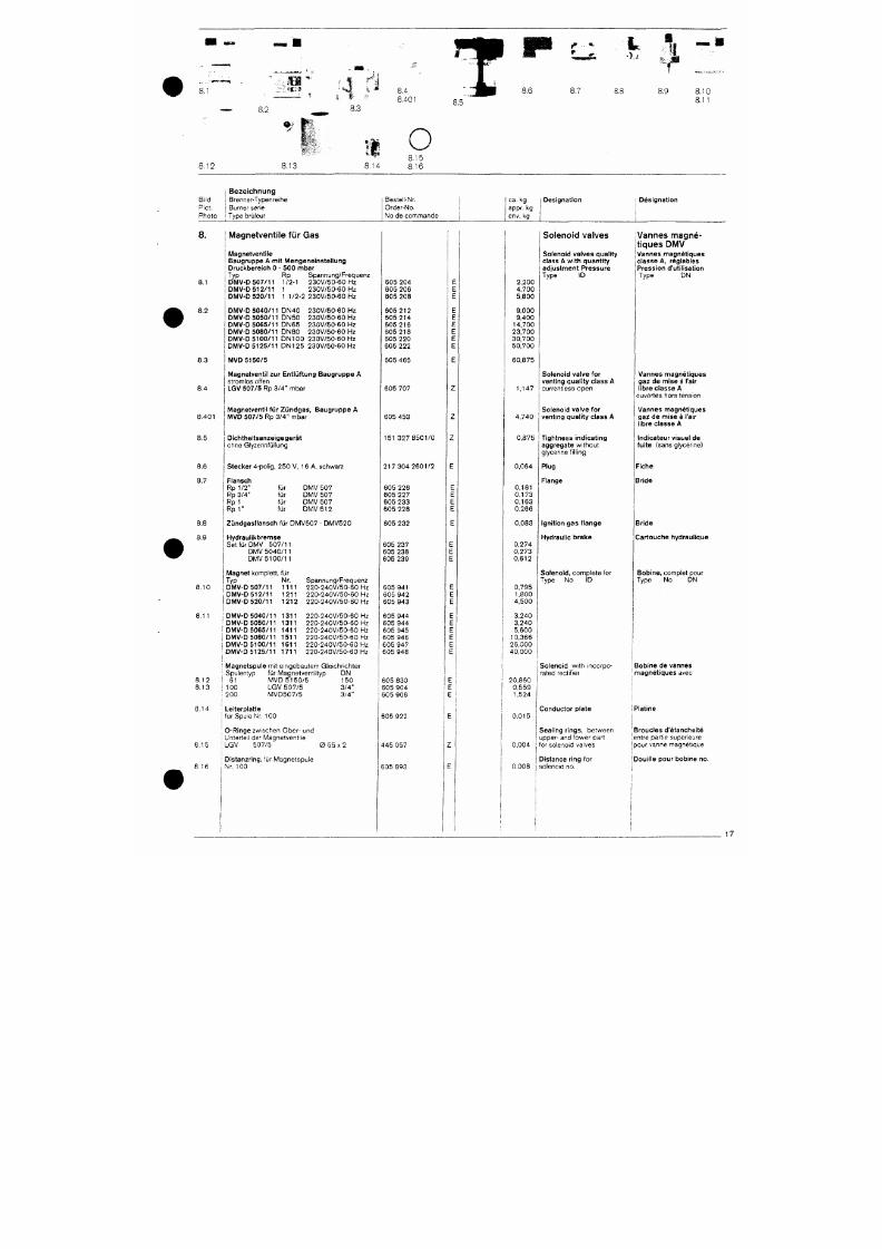
7/18/2019 M14 Thermal Fluid
http://slidepdf.com/reader/full/m14-thermal-fluid 426/486
•;.il
8.2
8.3
U
i.401
• • > /
8.6
8.8
8.9
3.10
3.11
8.12 8.13
111
»-If*
;,14
O
8.15
8.16
j Bezeichnung
Bi l d
I
Brenner-Typenre ihe
Piet . i Burner serie
P h o t o
I
Type brüleur
Beste l l -Nr.
Orde r -No .
N o d e c o m m a n d e
ca .
kg
appr.
kg
env. kg
Des igna t ion I Des igna t ion
8.
8.1
8.2
8.3
8.4
. 401
Magnetventile für Gas
Magnetventi le
Baugruppe A mit Mengene ins te l lung
Druckbere ich 0 - 500 mbar
Ty p
Rp
Spannung /F requenz
D M V - D 5 0 7 / 1 1
1/2-1
2 3 0 V / 5 0 - 6 0
Hz
D M V - D 5 1 2 / 1 1 1 2 3 0 V / 5 0 - 6 0 H Z
D M V - D 5 2 0 / 1 1
1 1/2-2
2 3 0 V / 5 0 - 6 0
Hz
D M V - D 5 0 4 0 / 1 1 D N 4 0
D M V - D 5 0 5 0 / 1 1 D N 5 0
D M V - D 5 0 6 5 / 1 1 D N 6 5
D M V - D 5 0 8 0 / 1 1
D N 8 0
D M V - D 5 1 0 0 / 1 1 D N 1 0 0
D M V - D 5 1 2 5 / 1 1 D N 1 2 5
M V D 5 1 5 0 / 5
2 3 0 V / 5 0 - 6 0 Hz
2 3 0 V / 5 0 - 6 0 Hz
2 3 0 V / 5 0 - 6 0
H z
2 3 0 V / ' 5 0 - 6 0
H z
2 3 0 V / 5 0 - 6 0 H z
2 3 0 V / 5 0 - 6 0 Hz
Magnetvent i l zur En t lü f tung Baugru ppe A
stromlos of fen
L G V 5 0 7 / 5 Rp 3/4" mba r
Magnetventi l für Z ü n d g a s , B a u g r u p p e A
M V D 5 0 7 / 5 Rp 3/4 " mba r
605 204
605
206
605 208
605 212
605 214
605 216
605
218
605 220
605 222
605 465
605 707
605 453
2,200
4,700
5,800
9,000
9,400
14,700
23,700
30,700
50,700
60,875
1,147
Solenoid valves
Solenoid valves qual i ty
class A wi th quant i ty
ad jus tment Pressure
Type
ID
4,740
Soleno id va lve for
venting qual i ty c lass
A
current less open
Soleno id va lve for
venting qual i ty c lass A
Vannes magné-
tiques DMV
Vannes magnét iques
c lasse A, réglables
Pression d'ut i l isat ion
Type
DN
Vannes magnét iques
ga z
de
m i s e
ä
I'air
l ibre classe A
ouvertes hors tension
Vannes magnét iques
g a z de m i s e ä I'air
l ibre classe A
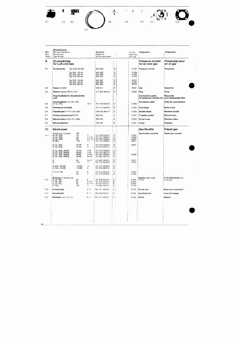
7/18/2019 M14 Thermal Fluid
http://slidepdf.com/reader/full/m14-thermal-fluid 427/486
9 .1
9 .2 9 .3
9.5
'J-
. TI '
9 .6 9 .7
4
- fc
1 0 . ' 10 .2
Bi ld
Pict .
Pho to
Bezeichnung
Brenne r -Typen re i he
Burner ser ie
Type brOleur
Beste l i -Nr.
Orde r -No .
N o d e c o m m a n d e
ca . k g
appr. kg
env. kg
Des igna t ion
I Designation
9.
9.1
9.2
9.3
9.4
9.5
9.6
Druckwächter
für Luft und Gas
D r u c k w ä c h t e r T y p L G W 5 0 A 2 P
T y p G W 50 A4
T y p G W 150 A 4
T y p G W 5 0 0 A 4
T y p G W 5 0 A 2
Ty p G W 150 A 2
Ty p G W 5 0 0 A 2
K a p p e f ü r LGW
S t e c k e r 4 -po l i g , 250 V , 16 A
Anschlußteile für Druckwächter
Luft
Ansch lußkabe l 4 x 0 , 7 5 x 750
G , G L , R G L
Rohrflansch konnplett
Doppe ln ippe l R 1 /4 " x 50 (Gas)
5-11
691 353
691 355
691 356
691 357
691 367
691 368
691 369
446 011
2 1 7 3 0 4 2 6 0 2 / 2
1 5 1 3 1 6 2 4 0 1 / 2
1 5 1 3 1 3 2 4 0 2 / 2
1 3 9 0 0 0 2 6 0 1 / 7
0 , 1 9 0
0,258
0,256
0,275
0,207
0,256
0,275
0 , 0 0 1
Pressure monitor
j
Pressostat pour
for air an d gas air et gaz
P r e s s u r e moni tor
0,064
0,064
0,055
0,028
Cap
Plug
Connection parts
for pressure monitor-air
Connection cable
Pipe f l ange
Double n ipp le
Pressos ta t
C a p u c h o n
F iche
R a c c o r d s
p o u r p r e s s o s t a t
d'air
Cable de raccordement
Bride å tube
M a m e l o n d o u b l e
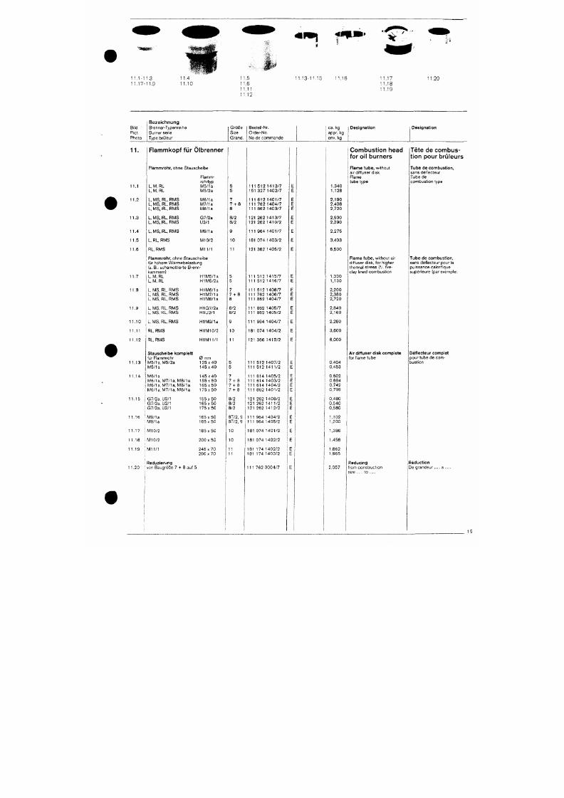
7/18/2019 M14 Thermal Fluid
http://slidepdf.com/reader/full/m14-thermal-fluid 428/486
1 1.1-1 1.3
1
1,17-1
1.9
11.5
11,6
1 1.1 1
11.12
11.1 3-1 1.15 1,16
1 1.17
1 1.18
1 1.19
11.2C
Bi l d
Piet .
Pho to
B e z e i c h n u n g
Brenner-Typenre ihe
Burner serie
Type brü leur
Größe
Size
Grand .
Beste l l -Nr.
Orde r -No .
No de commande
ca . kg
appr. kg
env. kg
Des igna t ion
Des igna t ion
11.
11 .2
11 .3
11 .4
11 .5
11 .6
Flammkopf für Olbrenner
Flammrohr , ohne S tausche ibe
L, M, RL
L, M, RL
L, MS, RL, RM S
L, MS, RL, RMS
L, MS, RL, RMS
L, MS, RL, RMS
L, MS, RL, RMS
L, MS, RL, RMS
L, RL,
RMS
RL, RMS
F lamm
rohrtyp
M 5 / 1 a
M 5 / 2 a
M B / I a
M 7 / 1 a
M 8 / 1 a
G 7 / 2 a
U2 /1
M 9 / 1 a
M I O / 2
M 1 1 / 1
Flammrohr , ohne S tausche ibe
fü r höhe re Wärmebe las tung
(z. B. : schamott ier te Brenn
kammern)
5
5
7
7 - h 8
8
8 /2
8 /2
1 0
11
1 1 1 5 1 2 1 4 1 2 / 7
1 5 1 3 2 7 1 4 0 2 / 7
1 1 1 6 1 2 1 4 0 1 / 7
1 1 1 7 6 2 1 4 0 4 / 7
1 1 1 8 6 2 1 4 0 3 / 7
1 2 1 2 6 2 1 4 1 3 / 7
1 2 1 2 6 2 1 4 1 0 / 2
1 1 1 9 6 4 1 4 0 1 / 7
1 8 1 0 7 4 1 4 0 3 / 2
1 2 1 3 6 2 1 4 0 5 / 2
1,340
1,128
2 ,190
2 ,408
2 ,720
2 ,900
2 ,390
2 ,275
3,403
6,500
Combustion head
for oil burners
F l a m e l u b e , w i t hou t
a i r d i f fuser d isk
Flame
tube t ype
Flame tube , wi thout a i r
d i f fuser d isk, for h igher
thermal s t ress ( f . i. f i re
c l ay l i ned combust i on
Tete de combus
tion pour bruleurs
Tube de combust ion ,
sans déf lecteur
Tube de
combust i on t ype
Tube de combust ion ,
sans déf lecteur pour la
puissance ca lor i f ique
supér ieure (par exemple:
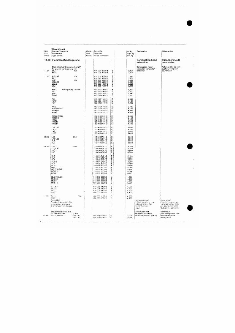
7/18/2019 M14 Thermal Fluid
http://slidepdf.com/reader/full/m14-thermal-fluid 429/486
Bi ld
Piet.
Pt io to
i B e z e i c h n u n g
i Brenner-Typenre ihe
Burner ser ie
Type brCileur
i Größe
: Size
1
G r a n d .
; Beste l l -Nr.
: Orde r -No .
i No de commande
ca . k g
appr. kg
env. kg
Des igna t ion
Des igna t ion
11.30 Flammkopfverlängerung
11.31
11 .32
; F lammkopfver längerung , kompl . '
' f ü r B renne r Ve r i änge rung mm
L 5 Z 1 0 0
RL5
120
150
Ver l änge rung 1 50 mm
L 7 Z / L 8 Z
RL7
L 5 Z
L 7 Z / L 8 Z
L 8 Z / 2
L 9 Z
RL5
RL7
RLS
R L 8 / 2
RL9
R L 1 0
R L 1 1
M 5 Z
M S 7 Z / M S 8 Z
M S 8 Z / 2
M S 9 Z
1 1 0 0 0 0 2 9 0 1 / 2
1 1 0 0 0 9 8 1 0 1 / 2
1 1 0 0 0 0 3 0 0 1 / 2
1 1 0 0 1 0 5 8 0 1 / 2
1 1 0 0 0 0 3 3 0 1 / 2
1 1 0 0 0 0 3 4 0 1 / 2
1 1 0 0 0 0 4 6 0 1 / 2
1 1 0 0 0 6 7 5 0 1 / 2
1 1 0 0 0 9 8 2 0 1 / 2
1 1 0 0 1 0 5 9 0 1 / 2
1 1 0 0 0 2 4 2 0 1 / 2
1 1 0 0 0 2 4 6 0 1 / 2
1 1 0 0 0 6 7 6 0 1 / 2
1 8 0 0 0 0 4 6 0 1 / 2
1 8 0 0 0 0 2 4 0 1 / 2
1 1 0 0 1 0 8 1 0 1 / 2
1 1 0 0 1 0 8 3 0 1 / 2
1 1 0 0 1 0 8 5 0 1 / 2
1 1 0 0 1 0 8 7 0 1 / 2
E
E
E
E
E
E
E
E
E
E
E
E
E
E
E
E
E
E
E
2 . 1 0 0
2 , 1 0 0
2 , 6 9 0
2 , 7 5 0
2 , 4 2 8
2 , 9 2 0
3,000
3,000
3,500
3,500
3,640
3,650
4 , 3 2 0
4 , 1 0 0
4 , 3 0 0
3,420
4 , 1 0 9
4 , 8 8 3
4 , 9 2 2
Com bust ion head
extension
C o m b u s t i o n h e a d
e x t e n si o n c o m p l e t e "
for burner
Rallonge tete de
combust ion
Ral longe te te de com
bus t ion , comple te *
pour brü leur
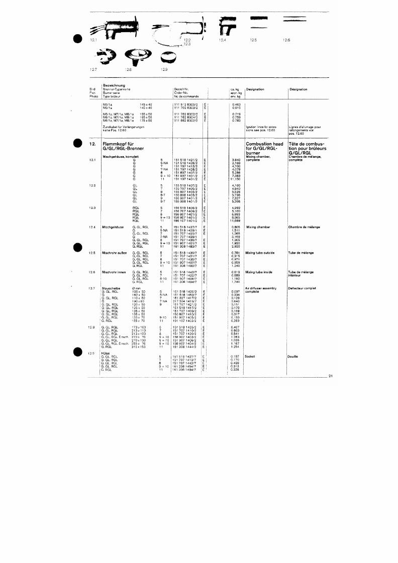
7/18/2019 M14 Thermal Fluid
http://slidepdf.com/reader/full/m14-thermal-fluid 430/486
12.5
12.6
Bi l d
Piet .
Pho to
12.
12 .1
12 .2
B e z e i c h n u n g
; Brenner-Typenre ihe
j Burner sene
[ Type brü leur
M 5 / 1 a 1 4 5 x 4 0
l M 6 / 1 a 1 4 5 x 4 0
M 6 / 1 a, M 7 / 1 a . M 8 / l a 1 5 5 x 5 0
M 5 / 1 a , M 7 / 1 a . M 8 / 1 a 1 6 5 x 5 0
M 6 / 1 a , M 7 / 1 a , M 8 / 1 a 1 7 5 x 5 0
Zündkabe l f ü r Ve r l änge rungen
siehe Pos. 12 .60
Flammkopf für
G/GL/RGL-Brenner
Mischgehäuse , komple t t
G
G
G
G
G
G
G
G L
G L
G L
5
5 -NA
7
7 -NA
8
9 + 10
11
5
7
8
Beste l l -Nr ,
Orde r -No .
N o d e c o m m a n d e
1 1 1 5 1 2 8 3 0 5 / 2
1 1 1 7 6 2 8 3 0 3 / 2
1 1 1 7 6 2 8 3 0 2 / 2
1 1 1 7 6 2 8 3 0 4 / 2
1 1 1 8 6 2 8 3 0 2 / 2
1 5 1 5 1 8 1 4 2 1 / 2
1 5 1 5 1 8 1 4 2 8 / 2
1 5 1 7 0 7 1 4 1 3 / 2
1 5 1 7 0 7 1 4 2 8 / 2
1 5 1 8 0 7 1 4 0 7 / 2
1 5 1 9 0 7 1 4 0 1 / 2
1 9 1 1 0 7 1 4 0 1 / 2
1 5 5 5 1 8 1 4 0 7 / 2
1 5 5 7 0 7 1 4 0 5 / 2
155 807 140 3 /2
j oa. kg
1 appr. kg
env. kg
E 1
E
E
E
E
E
E
E
E
E
E
E
E
E
E
0 ,463
0 ,615
0 ,719
0 ,759
0 ,783
3 . 8 4 0
2 , 1 6 3
4 , 7 0 0
4 , 0 7 9
5 ,286
7 ,383
1 1 , 1 5 0
4 , 1 0 0
4 , 9 4 0
5 ,526
i Des igna t ion
Ign i t ion l ines for exten
sions see pos, 12.60
Combustion head
for G/GL/RGL-
burner
Mix ing chamber ,
c o m p l e t e
Des igna t ion
Lignes d 'a l lumage pour
ra l longements vo i r
p o s . 1 2 .60
Tete de combu s
t ion pour brüleurs
G/GL/RGL
C h a m b r e d e m e l a n g e ,
c o m p l e t e
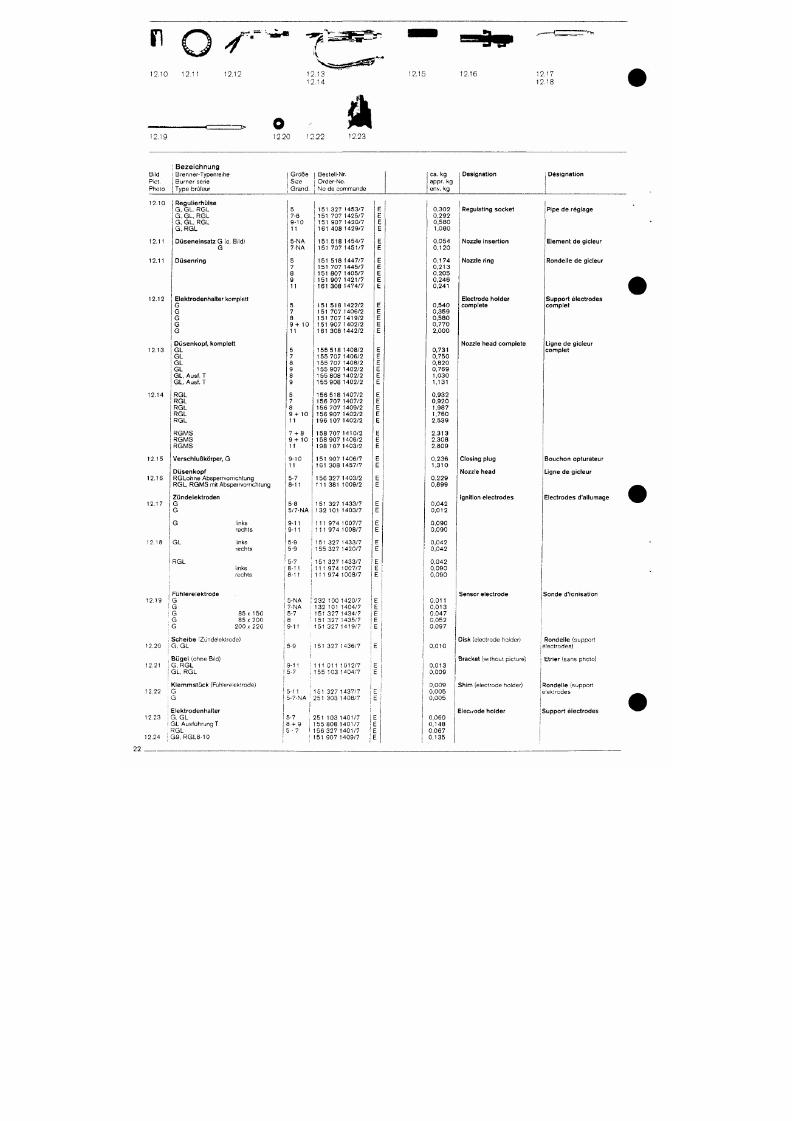
7/18/2019 M14 Thermal Fluid
http://slidepdf.com/reader/full/m14-thermal-fluid 431/486
^
o
^-^
2.10 12,11 12.12
12.19
3> O
12.20 12.22 12.23
12.15 12.16
12.1;
12 . U
Bi ld
PiCt.
Photo
Bezeichnung
Brenne r -Typen re i he
Burner ser ie
Type b rü l eu r
1
G r o ß e
1
Beste l l -Nr.
j S i ze j Orde r -N o .
1
Grand . ; No de comm ande
ca .
k g
app r . kg
env. kg
Des igna t ion Des igna t ion
12 .10
12 .11
12 .11
12 .12
12 .13
\
Regu l ie rhü lse
1 G , G L . R G L
i G , G L , R G L
G , G L , R G L
G , R G L
D ü s e n e i n s a t z G {o. Bild)
G
D ü s e n r i n g
Elek t rodenha l te r
komplet t
G
G
G
G
G
Düsenkopf , komple t t
G L
G L
G L
G L
G L ,
Ausf.
T
G L , Ausf.
T
5
7-8
9 -10
11
5 -NA
7-NA
5
7
8
9
11
5
7
8
9 + 1 0
11
5
7
8
9
8
9
1 5 1 3 2 7 1 4 5 3 / 7
151 707 1425 /7
1 5 1 9 0 7 1 4 2 0 / 7
1 6 1 4 0 8 1 4 2 9 / 7
1 5 1 5 1 8 1 4 5 4 / 7
1 5 1 7 0 7 1 4 5 1 / 7
1 5 1 5 1 8 1 4 4 7 / 7
151 707 1445 /7
1 5 1 8 0 7 1 4 0 5 / 7
1 5 1 9 0 7 1 4 2 1 / 7
1 6 1 3 0 8 1 4 7 4 / 7
1 5 1 5 1 8 1 4 2 2 / 2
1 5 1 7 0 7 1 4 0 6 / 2
1 5 1 7 0 7 1 4 1 9 / 2
1 5 1 9 0 7 1 4 0 2 / 2
1 6 1 3 0 8 1 4 4 2 / 2
1 5 5 5 1 8 1 4 0 8 / 2
1 5 5 7 0 7 1 4 0 6 / 2
1 5 5 7 0 7 1 4 0 8 / 2
1 5 5 9 0 7 1 4 0 2 / 2
1 5 5 8 0 8 1 4 0 2 / 2
1 5 5 9 0 8 1 4 0 2 / 2
E
E
E
E
E
E
E
E
E
E
E
E
E
E
E
E
E
E
E
E
E
E
0,302
0,292
0,580
1 ,080
0.054
0 , 1 2 0
0 , 1 7 4
0 , 2 1 3
0,205
0,246
0 , 2 4 1
0,540
0,359
0,580
0,770
2 , 0 0 0
0 , 7 3 1
0,750
0,820
0,769
1 ,030
1,131
Regulat ing socket
Nozzle inser t ion
Nozzle r ing
Electrode holder
comple te
Nozzle head comple te
P ipe de rég lage
Element de g ic leur
Rondel le de gicleur
Suppor t e lec t rodes
c o m p l e t
Ligne de gicleur
c o m p l e t
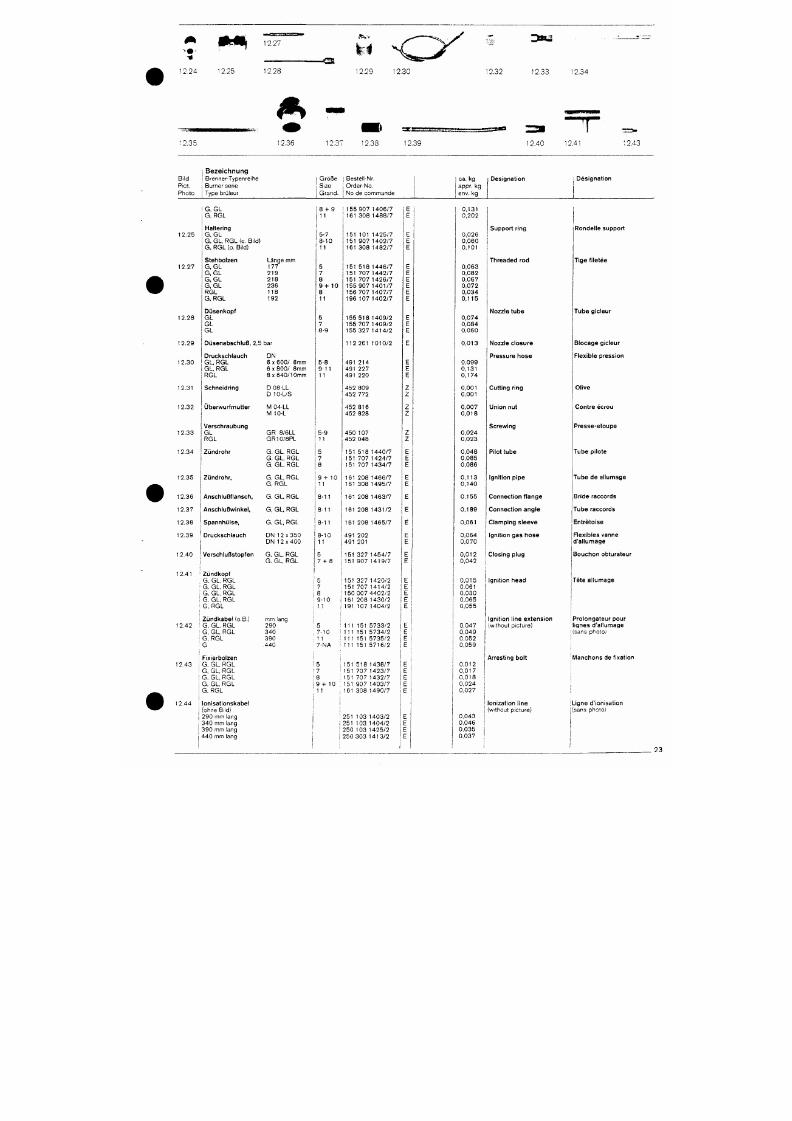
7/18/2019 M14 Thermal Fluid
http://slidepdf.com/reader/full/m14-thermal-fluid 432/486
i ' ^ n
12.27
12.24 12.25 12.28
- O
12.29 12.30 12.32
3su
12.33 12.34
12.35
ÄB^%
• • •
12.36 12.37
12.38
rxs:
12.39 12.40 12.41
12.43
Bi l d
Piet .
Pho to
1 B e z e i c h n u n g
j Brenner-Typenre ihe
i Burner sene
I Type brQteur
1
G r ö ß e
i Size
I Grand .
; Beste l l -Nr.
j Orde r -No .
1 No de com man de
c a.
k g
appr. kg
env. kg
Des igna t ion
Des igna t ion
1 2 . 2 5
12.27
1 2 . 2 8
1 2 . 2 9
1 2 . 3 0
G, GL
G, RGL
Haltering
G, GL
G, GL, RGL {o. Bi ld)
G, RGL (o. Bi ld)
S t e h b o l z e n Länge mm
G, GL 177
G, GL 219
G , G L 2 1 8
G , G L 2 3 6
R G L 1 1 3
G, RGL 192
Düsenkopf
G L
G L
G L
Düsenabsch luB, 2 ,5 bar
Drucksch lauch
G L , R G L
G L ,
R G L
R G L
D N
6
X
6 0 0 / 8 m m
6
X
8 0 0 / 8 m m
8 x 6 4 0 / 1 0 m m
8 + 9
11
5-7
8 - 1 0
11
5
7
8
9 + 10
8
11
5
7
8-9
5-8
9 -11
11
1 1 5 5 9 0 7 1 4 0 6 / 7
1 6 1 3 0 8 1 4 8 8 / 7
151 101 1425 /7
1 5 1 9 0 7 1 4 0 2 / 7
1 6 1 3 0 8 1 4 8 2 / 7
1 5 1 5 1 8 1 4 4 6 / 7
1 5 1 7 0 7 1 4 4 2 / 7
1 5 1 7 0 7 1 4 2 6 / 7
1 5 5 9 0 7 1 4 0 1 / 7
1 5 6 7 0 7 1 4 0 7 / 7
1 9 6 1 0 7 1 4 0 2 / 7
1 5 5 5 1 8 1 4 0 9 / 2
1 5 5 7 0 7 1 4 0 9 / 2
1 5 5 3 2 7 1 4 1 4 / 2
E
E
E
E
E
E
E
E
E
E
E
E
1 1 2 2 6 1 1 0 1 0 / 2
491 214
491 227
4 9 1 2 2 0
0 , 1 3 1
0,202
0,026
0,060
0 ,101
0,063
0,082
0,067
0,072
0,034
0 , 1 1 5
0,074
0,084
0,060
0 , 0 1 3
0.099
0 , 1 3 1
0 , 1 7 4
Suppor t r ing
Threaded rod
N o z z l e t u b e
Nozzle c losure
Pressure hose
Ronde l le suppor t
TIge f i letée
Tube gicleur
Blocage g ic leur
Flexible pression
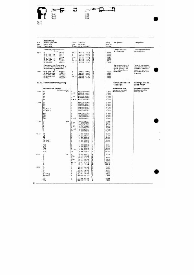
7/18/2019 M14 Thermal Fluid
http://slidepdf.com/reader/full/m14-thermal-fluid 433/486
p
2.44
12.45
12.53
12.55
-•mjf
^^^g^s:^
12.52
12.54
12.56
Bild
Piet.
Photo
12.44
12.45
12.50
12.51
Bezeichnung
Brenner-Typenreihe
Burner serie
Type brüleur
Flammrohr,
ohne Stauscheibe
0 mm
G G5/3-a
G, GL.RGL 200 G5/1a
G,
G L,
RGL 250 G7/1a
G G7/3-A
G, GL, RGL 265 G7/2a
G, GL, RGL 325 UG2/1a
G, RGL 380 UG3/1a
Flammrohr, ohne Stauscheibe
für höhere Wärmebelastung (z. B.:
schamottierte Brennkammern)
0 mm
G, GL, RGL 200 H1M6/1a
G, GL, RGL 250 H1G7/1a
G, GL, RGL 265 H1G7/2a
G, GL, RGL 325 H1UG2/1a
G, RGL H1UG3/1a
Flammkopfverlängerung
Mischgehäuse, komplett
Verlängerung mm
G 100
G
Größe
Size
Grand.
5-NA
5
7
7-NA
8
9 + 10
11
5
7
8
9 + 1 0
11
5
5-NA
Bestell-Nr.
Order-No.
No de commande
151 518 1432/2
111 612 1401/7
151 707 1412/7
151 707 1427/2
121 262 1413/7
161 208 1462/7
161 308 1471/7
111 612 1408/7
151 707 1430/7
111 862 1405/7
161 208 1471/7
161 309 1401/7
150 003 0901/2
150 518 1406/2
E
E
E
E
E
E
E
E
E
E
E
E
E
E
ca. kg
appr. kg
env. kg
2,012
2,190
2,720
5,840
2,900
3,500
7,410
2,200
2,980
2,640
3,480
7,450
4,876
2,345
Designation
Flame tube ,
without
air diffuser disk
Flame tube , without air
diffuser disk for higher
thermal stress (f.i. fire
clay lined combustion
chambers)
Combustion head
extension
Combustion head
extension complete
Extended by mm
1 Designation
t
1
Tube
de combustion,
sans deflecteur
Tube de combustion
sans deflecteur pour la
puissance calorifique
supérieure (par exem- |
pie:
chambre de com-
chamotte)
Rallonge tete de
combust ion
Rallonge tete de com
bustion,
complete
Rallonge mm
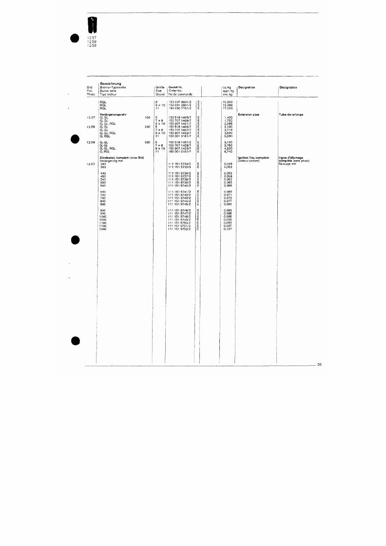
7/18/2019 M14 Thermal Fluid
http://slidepdf.com/reader/full/m14-thermal-fluid 434/486
i
2.57
12.58
12.59
Bild
Piet.
Photo
1 Bezeichnung
j Brenner-Typenreihe
1
Burner serie
1 Type brijleur
Größe
Size
Grand.
Bestel -Nr. |
Order-No. i
No de commande
i
ca .
k g
appr. kg
1 env. kg
Designation Designation
12.57
12.58
12.59
12.60
RGL
RGL
RGL
Veriängerungsrohr
G GL
GL
GL, RGL
GL
GL
GL, RGL
RGL
100
200
G GL 300
G
GL
G
GL, RGL
G RGL
Zündkabel, komplett (ohne Bild)
Verlängerung mnn
340
390
440
490
540
590
640
8
9 + 1 0
11
5
7 + 8
9 + 1 0
5
7 + 8
9 + 10
11
5
7 + 8
9 + 10
11
150 007 8601/2
150 001 2901/2
190 000 1701/2
150 518 1405/7
150 707 1406/7
150 907 1421/7
150 518 1406/7
150 707 1407/7
150 907 1422/7
160 001 3101/7
150 518 1401/2
150 707 1408/7
150 907 1423/7
160 001 0101/7
111 151 5734/2
111 151 5735/2
111 151 5736/2
111 151 5737/2
111 151 5738/2
111 151 5739/2
111 151 5740/2
E
E
E
E
E
E
E
E
E
E
E
E
E
E
E
E
E
E
E
E
E
10,800
12,986
1 7,000
1,400
1,752
2,285
2,190
2,716
3,520
6,280
3,120
3,780
4,920
8,740
0,049
0,052
0,055
0,058
0,062
0,065
0,066
Extension pipe
Ignition line, complete
(without picture)
Tube de rallonge
Ligne d'allumage
complete (sans photo)
Rallonge mm
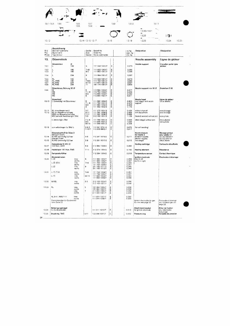
7/18/2019 M14 Thermal Fluid
http://slidepdf.com/reader/full/m14-thermal-fluid 435/486
13.1-13,3 13.4
«
m
13.5 13.7
13.6 13.8
13.9 13.10
13.-
• l < | | M H M M M # « # M P ~ * '
"
R
1 3 . 1 2 1 3 . 1 4 - 1 3 . 1 5 '
1 B e z e i c h n u n g
Bi l d B renne r -Typen re i he
Piet . j Burner sene
P h o t o 1 Type bru ieur
13.
13.1
13 .2
13 .3
13 .4
13 .5
13.6
13.7
13 .8
13 .9
13 .10
13 .11
Düsenstock
D ü s e n k r e u z 0
L 140
L 180
L 180
L 234
RL 140
RL , RM S 180
R L . R M S 2 3 4
R L . R M S 2 3 4
D ü s e n k r e u z , Boh run g 55 0
M
M S
M S
M S
Düsenkopf
L (zweistu f ig) mi t Düsenkreuz
RL ohne A bspe r rven t i l
G r ö ß e
S i ze
G r a n d .
5
7-1-8
8 /2
9
5
7 -8 /2
9H-10
11
5
7 - f - 8
8 /2
9
5
7 - H 8
8 /2
9
5-7
C
y
. 1 7 1 3 . 1 8 1 3 . 1 9
Beste l l -Nr.
Orde r -No .
No de commande
1 1 1 5 5 2 1 0 0 1 / 7
111 652 1002 /7
1 1 1 8 6 2 1 0 0 1 / 7
1 1 1 9 6 4 1 0 0 1 / 7
1 1 1 5 5 2 1 0 0 1 / 7
1 1 1 7 8 2 1 0 0 1 / 7
1 1 1 9 7 4 1 0 0 1 / 7
181 174 1001 /7
11 2 564 100 3 /7
1 1 2 7 6 4 1 0 0 3 / 7
1 1 2 8 6 6 1 0 0 3 / 7
1 1 2 9 6 4 1 0 2 1 / 7
1 1 1 5 6 2 1 0 0 3 / 2
1 1 1 7 5 2 1 0 0 1 / 2
1 1 1 8 6 2 1 0 0 2 / 2
1 1 1 9 6 4 1 0 0 2 / 2
1 1 1 2 7 3 1 0 0 1 / 2
e
E
E
E
E
E
E
E
E
E
E
E
E
E
E
E
E
c a.
kg
appr. kg
env. kg
0 . 2 7 3
0 , 3 9 0
0 , 3 6 5
0 , 5 5 7
0 , 2 7 3
0 . 3 6 0
0 , 5 5 7
0 , 6 0 0
0 , 3 7 7
0 , 4 9 6
0 , 4 8 2
0 ,671
0 , 8 2 0
0 , 9 7 0
0 , 9 5 9
1,175
0 , 4 2 0
1 3 . 2 0 / 1 3 . 2 1
1 3 . 2 2
1 3 . 2 3
Des igna t ion
Nozzle assembly
Nozzle suppor t
N o z z l e s u p p o r t ho le 55 0
N o z z l e h e a d
( two stage) wi th nozzle
support
wi thout shut-o f f
I tJ l
1 3 . 2 4 1 3 . 2 5
1
Des igna t ion
Ligne de gicleur
Croisi l lon porte l igne
g ic leur
Cro is i l lon 0 55
Ligne de gicleur
(deux al lures)
sans b l ocage
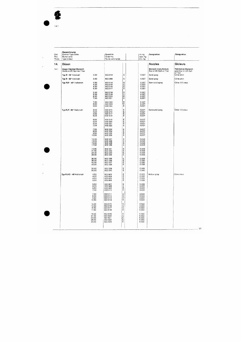
7/18/2019 M14 Thermal Fluid
http://slidepdf.com/reader/full/m14-thermal-fluid 436/486
5 P
1 4 . 1
B i l d
Piet .
Pho to
Bezeichnung
Brenne r -Typen re i he
Burner ser ie
Type brü leur
Beste l l -Nr.
Orde r -No .
No de commande
ca. kg
appr. kg
env, kg
Des igna t ion Des igna t ion
14.
14 .1
Düsen
Düsen Fabr ika t Monarch
Größe in US Gph bei 7 bar
Ty p R - 45° Vol lst rah l
Ty p R - 60° Vol lst rah l
Typ PLP - 45 ° Halbst rah l
Typ PLP - 60° Halbst rah l
3,50
3,50
3,50
4,00
4,50
5,00
5,50
6,00
6,50
7,00
7,50
8,50
9,50
3,50
4,00
4,50
5,00
602 314
602 366
602 014
6 0 2 0 1 5
602 016
602 017
602 018
602 019
602 020
602 021
602 022
6 0 2 0 2 3
602 024
602 215
602 216
602 217
602 218
0,027
0,027
0,027
0,027
0,027
0,027
0,027
0.027
0,027
0,027
0,027
0,027
0,027
0,027
0,027
0,027
0,027
Nozzles
Monarch manufac ture
Size in US G ph at 7 bar
Sol id spray
Sol id spray
Semi -so l i d sp ray
Gicieurs
Fabr ica t ion Monarch
g randeu r en US Gph
ä 7 bar
Cöne -p l e i n
Cöne p l e i n
C ö n e 112 creux
Semi -so l i d sp ray
Cöne 1/2 creux
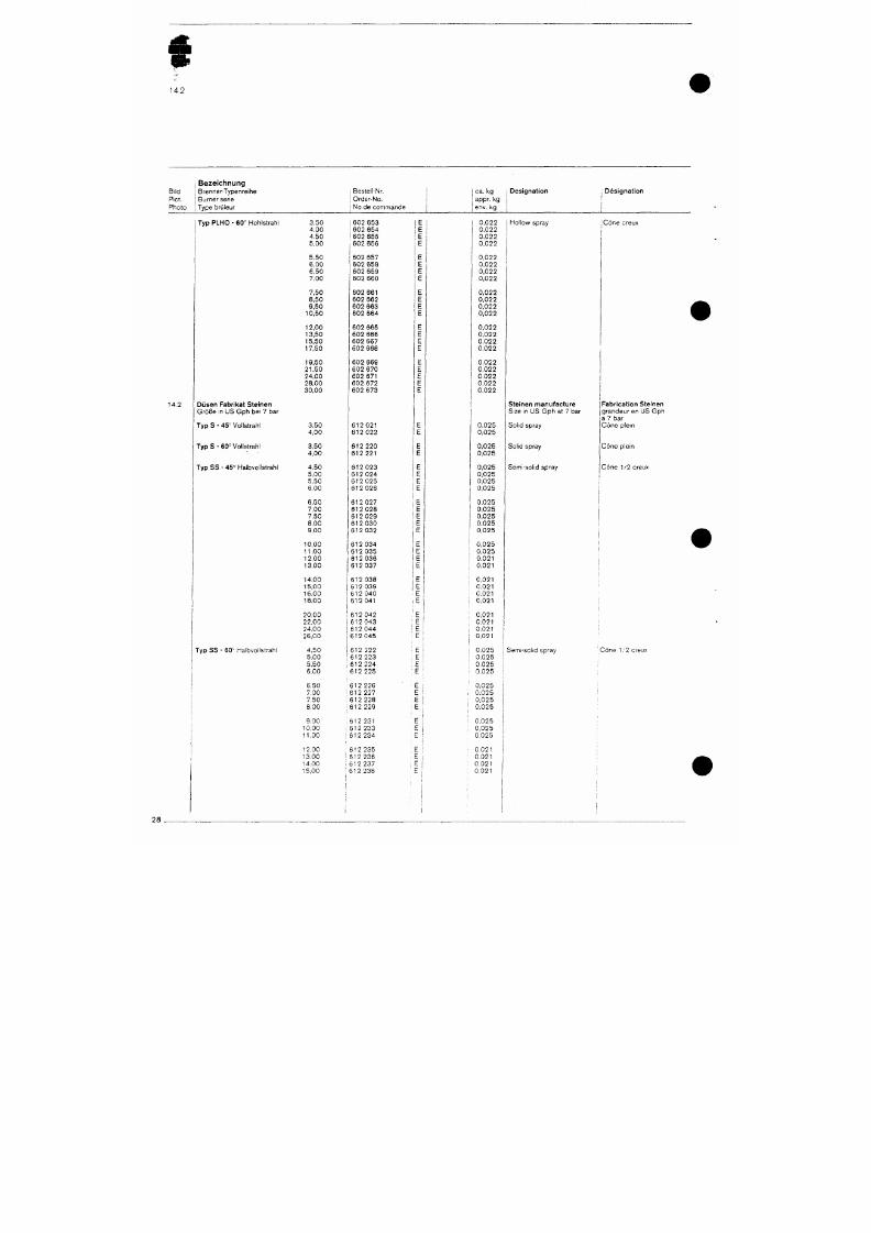
7/18/2019 M14 Thermal Fluid
http://slidepdf.com/reader/full/m14-thermal-fluid 437/486
14,2
Bi ld
Piet.
Pho to
Bezeichnung
Brenner-Typenre ihe
Burner sene
Type brOleur
i Bestel l-Nr.
I Orde r -No .
I
No de
c o m m a n d e
I ca.
kg
I appr. kg
I env.
kg
Des igna t ion Des igna t ion
Typ PLHO
- 60°
Hohlst rah l
14.2
Düsen Fabr ika t S te inen
G r ö ß e in
US
G p h
be i
7 bar
3 , 5 0
4 , 0 0
4 , 5 0
5 ,00
5 ,50
6 ,00
6 ,50
7 ,00
7 ,50
8 ,50
9 ,50
1 0 , 5 0
12 ,00
13 ,50
15 ,50
17 ,50
19 ,50
2 1 , 5 0
2 4 , 0 0
2 8 , 0 0
3 0 , 0 0
602
653
602 654
602
655
602
656
602 657
602 658
602 659
602 660
602 661
602 662
602 663
602 664
602
665
602 666
602 667
602 668
602 669
602 670
602 671
602 672
602
673
0,022
0,022
0,022
0,022
0.022
0,022
0,022
0,022
0,022
0,022
0,022
0,022
0,022
0,022
0,022
0,022
0,022
0,022
0,022
0,022
0,022
Hol low spray
•Cöne creux
Ste inen manufac ture
Size in
US
G p h at 7
bar
Fabr ica t ion Ste inen
g r a n d e u r
en US Gph
ä 7 bar
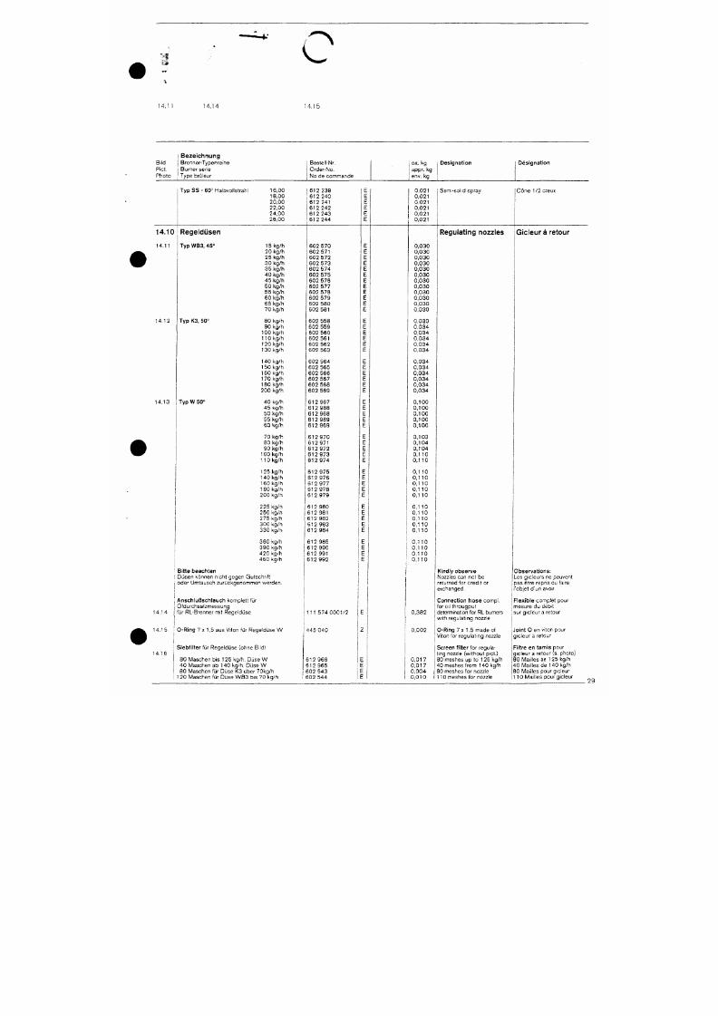
7/18/2019 M14 Thermal Fluid
http://slidepdf.com/reader/full/m14-thermal-fluid 438/486
"'I
c
14.1 1
14.14 14.15
Bi ld
Piet.
Pho to
B e z e i c h n u n g
1 Brenne r -Typen re i he
i Burner ser ie
1 Type brOleur
Beste l l -Nr.
Orde r -No .
N o d e c o m m a n d o
i ca. kg
I appr. kg
1 env. kg
D e s i g n a t i o n
Des igna t ion
Typ SS - 60° Halbvol lst rah l
1 6 , 0 0
1 8 , 0 0
2 0 , 0 0
2 2 , 0 0
2 4 , 0 0
2 6 , 0 0
612 239
6 1 2 2 4 0
612 241
6 1 2 2 4 2
612 243
612 244
0 , 0 2 1
0 .021
0 .021
0 ,021
0 , 0 2 1
0 , 0 2 1
Semi -so l i d sp ray C6 ne
1/2creux
14 .10
14 .11
Regeldüsen
Typ WB3, 45 °
14 .12
T yp K3, 50°
Regulating nozzles
Gicleur ä retour
15 kg /h
20 kg /h
25 kg /h
30 kg /h
35 kg /h
40 kg /h
45 kg/h
50 kg /h
55 kg /h
60 kg /h
65 kg /h
70 kg /h
80 kg /h
90 kg /h
100 kg /h
110 kg /h
1 20 kg /h
602 570
602 571
6 0 2 5 7 2
602 573
6 0 2 5 7 4
602 575
6 0 2 5 7 6
6 0 2 5 7 7
6 0 2 5 7 8
6 0 2 5 7 9
6 0 2 5 8 0
602 581
6 0 2 5 5 8
602 559
6 0 2 5 6 0
6 0 2 5 6 1
6 0 2 5 6 2
0 , 0 3 0
0 , 0 3 0
0 , 0 3 0
0 , 0 3 0
0 , 0 3 0
0 , 0 3 0
0 , 0 3 0
0 , 0 3 0
0 , 0 3 0
0 , 0 3 0
0 , 0 3 0
0 , 0 3 0
0 , 0 3 0
0 , 0 3 4
0 , 0 3 4
0 , 0 3 4
0 , 0 3 4
ii.mi'-'
^w^*
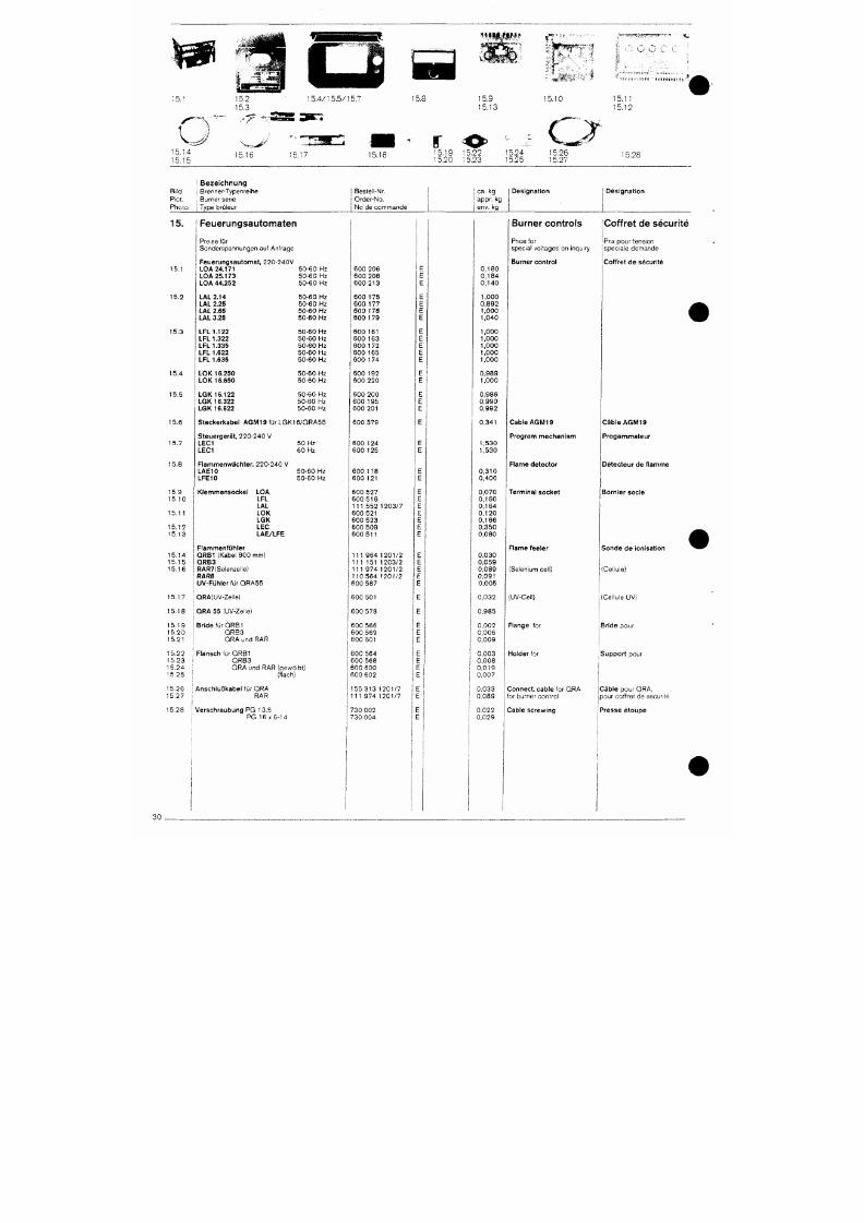
7/18/2019 M14 Thermal Fluid
http://slidepdf.com/reader/full/m14-thermal-fluid 439/486
15.14
15.15
15,16 15.17
15.1
15.8
r
15.9
15.13
15.19 15.22 15,24
15.20 15.23 15.25
15.10
15.26
15.27
i>i » t » f t t l '
o
15.11
15.12
15,28
Bild
Piet.
Photo
i Bezeichnung
I Brenner-Typenreihe
; Burner serre
} Type bruleur
Bestell-Nr.
Order-No.
No de commande
j ca. kg
appr. kg
1 env. kg
Designation Designation
15.
15 .1
15.2
15 .3
15 .4
15 .5
Feuerungsautomaten
Preise für
Sonde rspannungen au f An f rage
F e u e r u n g s a u t o m a t , 2 2 0 - 2 4 0 V
LOA 24.171 50 -6 0 Hz
L O A 2 5 . 1 7 3 50 -60 Hz
L O A 4 4 . 2 5 2 5 0 - 6 0 H z
LAL 2.14
LAL 2.25
LAL 2.65
LAL 3,25
L F L 1 . 1 2 2
LFL 1.322
LFL 1.335
LFL 1.622
LFL 1.635
LOK 16 .250
LOK 16 .850
LGK 16 .122
LGK 16 .322
LGK 16 .622
50 -60 Hz
5 0 - 6 0 H z
5 0 - 6 0 H z
5 0 - 6 0 H z
50 -60 Hz
50 -60 Hz
50 -60 Hz
50 -60 Hz
50 -60 Hz
5 0 - 6 0 H z
50 -60 Hz
50 -60 Hz
5 0 - 6 0 H z
50 -60 Hz
600 206
600 208
600 213
600 1 75
600 177
600 1 78
600 1 79
600 161
600 163
600 1 72
600 165
600 1 74
600 192
600 220
600 200
600 195
600 201
0 , 1 8 0
0 , 1 8 4
0 , 1 4 0
1 ,000
0,892
1 ,000
1 ,040
1 ,000
1 ,000
1 ,000
1 ,000
1 ,000
0,989
1,000
0,986
0,990
0,992
Burner controls
Price for
specia l vo l tages on inqui ry
Burner control
Coffret de sécurité
Prix pour tension
spec ia l e demande
Coffret de sécuri té

7/18/2019 M14 Thermal Fluid
http://slidepdf.com/reader/full/m14-thermal-fluid 440/486
o ^
6,5
16.6
16i
16,9
Bi ld
Piet.
Pho to
I B e z e i c h n u n g
j Brenner-Typenre ihe
i Burner sene
1 Type br i j leur
1
G r ö ß e
Size
j Grand .
Beste l l -Nr
Grde r -No .
No de commande
c a.
kg
app r , kg
env. kg
Des igna t ion
Des igna t ion
16.
16.1
16.2
16.3
16.4
16.5
Zündtrafo
Zündtrafo, 230V /50-60 Hz (2 x 5000V)
L. G. GL
RL,
RGL
G (2 X 7000V)
Zündtrafo (2 x 7000 V mit 100% ED)
L
RL, RGL
M
M S
RMS
G, GL, RGMS
Trafobügel
L
G,GL,RGL
G
G,GL,RGL
Tülle
LW 0 8
5-8
5-7
5/7-.NA
9-1OT
8-11
5
7-9
7-11
9-11
5-7
5-7
5/7-NA
7-11
603 100
603 077
603 112
111 211 1102/7
251 103 1101/7
151 907 1101/7
756 122
2,120
0,946
6,140
0,140
0,122
0,169
0,003
Ignition
transformers
Ignition transfornners
Attachment bracket
Bushing
Transformateur
d'al lumage
Transformateur
Etrier de fixation
Passage
• • » i »
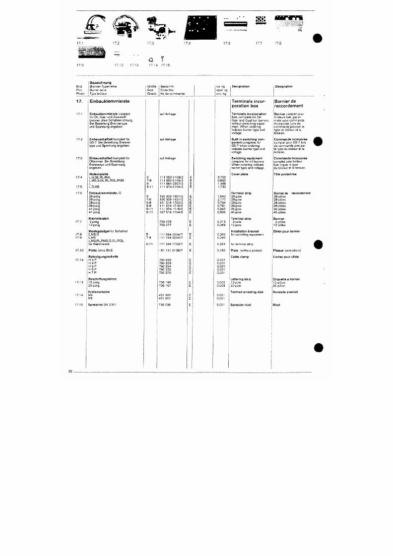
7/18/2019 M14 Thermal Fluid
http://slidepdf.com/reader/full/m14-thermal-fluid 441/486
/f^
17 1
1 7 . 9
1 7 . 2
1 7 . 1 2 1 7 . 1 3
1 7 . 3
1 7 . 1 4 1 7 . 1 5
1 7 . 4
» r ? - ^ - » W - ^ s i - T f l * * *
17.6
17 .7
ri
Bi ld
Piet .
B e z e i c h n u n g
Brenne r -Typen re i he
Burner ser ie
Ph oto I Type brü leur
Gr öße I Beste l l -Nr.
S i ze Orde r -No .
G r a n d , i N o d e c o m m a n d e
ca .
kg
appr. kg
env. kg
Des igna t ion
\ Des igna t ion
17.
17.1
17 .2
17 .3
17 .4
17 .5
Einbauklemmleiste
E i n b a u k l e m m l e i s t e komp le t t
f ü r Ö l - , Gas- u nd Zweistoff
b renne r ohne Scha l t e i n r i ch tung .
Be i Beste l l ung Brenne r t ype
und Spannung angeben .
Einbauscha l t te i l komplet t für
G5 -7 . Be i Beste l l ung Brenne r
t ype und Spannung angeben .
Einbauscha l t te t I komplet t für
Ö ib renne r . Be i Beste l l ung
Brenne r t yp und Spannung
angeben ,
Abdeckp la t te
L,G,GL,RL,RGL
L,MS,G,GL,RL,RGL,RMS
L
L,G,MS
5
7-8
9 -11
auf Anfrage
auf Anfrage
auf Anfrage
1 1 1 5 5 2 0 1 0 6 / 2
1 1 1 6 5 2 0 1 0 5 / 2
1 1 1 9 6 4 2 2 0 7 / 2
1 1 1 9 7 4 0 1 0 6 / 2
0 752
0 860
1,466
1,733
Terminals
incor
porat ion box
Termina ls incorpora t ion
box, comp le te f o r O i l -
Gas- and Dual fue l burners
w i thou t sw i t ch i ng equ ip
men t . W he n o rde r i ng
ind icate burner type and
vol tage.
Bui l t in swi tch ing co m
ponent c o m p l e t e , f o r
G5 -7 when o rde r i ng
ind icate burner type and
vol tage.
S w i t c h i ng e q u i p m e n t
complete for o i l burners
When o rde r i ng i nd i ca te
burner type and vo l tage.
Cover p la te
jBornier de
iraccordement
B o r n i e r comp le t pou r
b rü l eu rs
fuel,
gaz et
mi x te sans commande
inco rpo rée . Lo rs de
commande p rec i se r l e
type du brü leur e t la
tens i on .
C o m m a n d e i n c o r p o r é e
comp le t pou r G5 -7 l o rs
de commande p rec i se r
le type du brü leur e t la
tens i on .
C o m m a n d e i n c o r p o r é e
comp le t pou r b rü l eu r
fuel inquer le type
du brü leur e t la tension.
Töle protectrice
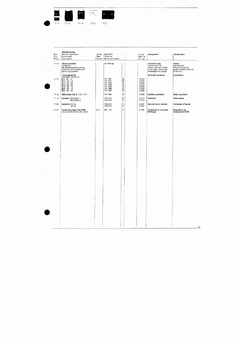
7/18/2019 M14 Thermal Fluid
http://slidepdf.com/reader/full/m14-thermal-fluid 442/486
17 .1 '
n n
7.1J 17.19 ' .20
17.21
Bi l d
Piet .
Pho to
B e z e i c h n u n g
Brenner-Typenre ihe
Burner serie
Type bruleur
G r ö ß e
Size
Grand .
Beste l l -Nr. j
Orde r -No .
No de c o m m a n d e |
ca .
kg
appr.
kg
env, kg
D e s i g n a t i o n Des igna t ion
1 7 . 1 7
1 7 . 1 8
1 7 . 1 9
1 7 . 2 0
17 .21
Ubers t romre la is
(ohne Bild)
Be i Beste l lung B renne r t ype ,
M o to r t ype , S t romstä rke und
Spannung angeben .
Leistungsschütz
2 3 0 / 3 8 0 V , 5 0 - 6 0 Hz
8
9 - 3 0 - 1 0
B 1 2 - 3 0 - 1 0
B 1 2 - 3 0 - 2 2
B 1 6 - 3 0 - 3 2
B 1 6 - 3 0 - 1 0
8 2 5 - 3 0 - 1 0
8 3 0
-
3 0
-
2 2
Hilfsschütz K22 E 2 S -H 2 Ö
Schalter 1300 Z i f f e r 1
1302 Z i f f e r
2
Ze i t zäh le r 50 Hz
6 0 Hz
Tempera turreg le r Typ ROB
2 2 0 - 2 4 0 V / 5 0 - 6 0 Hz, 65 -130°G
5-11
auf Anfrage
701 897
701
901
701 903
701 908
701
905
701 898
701
900
701 930
700 914
700 916
709 574
709
575
691 120
0 310
0 307
0 346
0 354
0 305
0 460
0 588
0 305
0 010
0 012
0 044
0 044
0 189
Over load re lay
(wi thout p icture)
When o rde r i ng i nd i ca te
burner type, motor type,
amperage and vo l t age .
Air break contactor
Relais
(sans photo)
Préc i se r le type du
brCileur moteur, intensité
et tension.
Contac teur
Auxi l iary contactor
Swi tches
Serv ice hours counte r
Tempera ture cont ro l le r
ROB type
Relais auxi l ia ire
in te r rup leur
C o m p t e u r d'heures
Regula teur de
t e m p e r a t u r e ROB
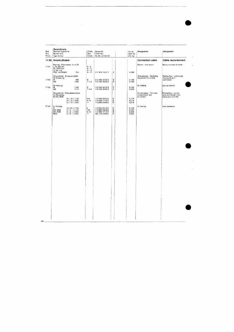
7/18/2019 M14 Thermal Fluid
http://slidepdf.com/reader/full/m14-thermal-fluid 443/486
Bi ld
Piet.
Photo
Bezeichnung
Brenne r -Typen re i he
Burner ser ie
Type brü leur
G r ö ß e
Size
Grand .
1 Beste l l -Nr.
1
Orde r -No .
i No de commande
1
ca.
kg
appr. kg
1 env. kg
D e s i g n a t i o n 1 D e s i g n a t i o n
1
1
17.50 Anschlußkabel
17 .51
17 .52
17 .53
17 .54
Brenner - Endschal ter , 2 x 0 ,75
L, M, MS und
RL , RM S und
G, GL und
R G L u n d R G M S 7 5 0
Olvo rwärmer - E i nbauscha l t t e i l
f ü r S teue rung
M 9 8 0
M S 1 0 4 0
für Heizung
M
M S
1 1 4 0
1 1 1 0
Olvo rwärmer - E i nbauk lemmle i s te
für Steuerung
M , M S , R M S
6 X 1,5 X 1100
6 X 1,5x1300
6
X
1,5
X
1 3 2 0
für Heizung
M
M S , R M S
M S , R M S
4 X 2, 5 X 1 1 4 0
4 x 4 X 1 1 0 0
4 x 4
X 1
300
5 - 9
5 - 1 1
5 - 10
9 - 1 1
5
7 -1 -8
5
7-1-8
5-8
9 -10
11
5
7-8
9 -10
1 1 1 9 7 4 1 2 0 1 / 7
2 1 2 3 6 4 2 2 0 4 / 2
1 1 2 7 6 2 0 0 0 3 / 2
1 1 2 5 5 2 0 0 1 3 / 2
1 1 2 7 6 2 0 0 0 2 / 2
1 1 2 9 6 4 0 0 0 2 / 2
1 1 2 9 6 4 1 7 1 8 / 2
1 1 2 8 8 2 0 0 0 4 / 2
1 1 2 5 5 2 0 0 1 3 / 2
1 1 2 6 5 2 0 0 0 3 / 2
1 1 2 9 6 4 1 7 1 7 / 2
0,089
0 , 1 8 0
0 , 1 6 0
0 , 1 5 2
0,240
0 , 1 7 5
0 , 2 1 4
0 , 2 1 4
0 , 1 5 2
0,237
0,348
Conn ection cable
Burner - l imi t swi tch
Oi l p rehea te r - Sw i t ch i ng
equ ipmen t f o r con t ro l
for heat ing
Oi l preheater - Terminals
i nco rpo ra t i on box
for contro l
for heat ing
Cable raccordement
Br i j l eu r -con tac t de b r i de
Réchau f feu r - commande
inco rpo rée pou r
c o m m a n d e
pou r pu i ssance
Réchauf feur - born ier
sans commande i nco r
po rée pou r con t rö i e
pou r pu i ssance
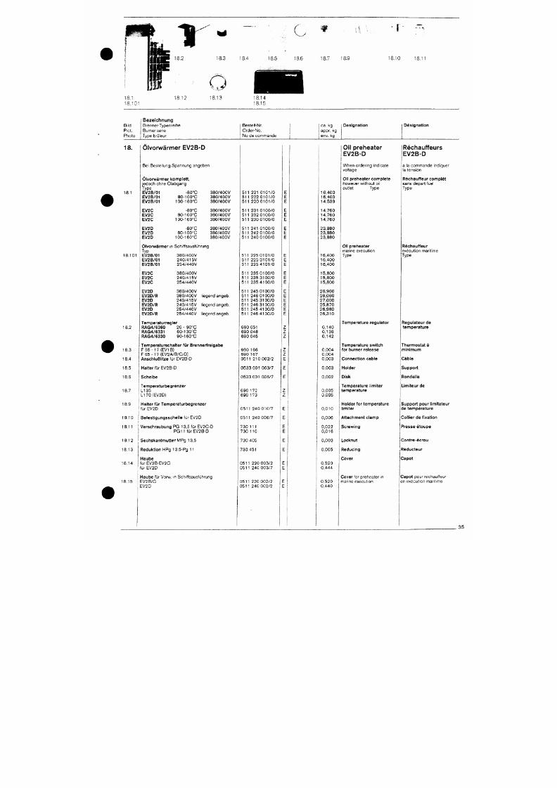
7/18/2019 M14 Thermal Fluid
http://slidepdf.com/reader/full/m14-thermal-fluid 444/486
18.12
18,101
18.13
18,4
18.5
C
18.6
18.7
18.9 18,10
18 ,1 1
B.ld
Piet .
Pho to
Bezeichnung
Brenne r -Typen re i he
Burner sene
Type brü leur
Beste i l -Nr ,
Orde r -No .
N o d e c o m m a n d e
ca. kg
appr. k g
env. kg
Des igna t ion Des igna t ion
18.
Olvorwärmer EV2B-D
Be i Beste l l ung Spannung angeben
Olvorwärmer komple t t ,
j edoch ohne Ö labgang
Type
E V 2 B / 0 1
E V 2 B / 0 1
E V 2 B / 0 1
EV2C
EV2C
EV2C
EV2D
EV2D
EV2D
-80°C
8 0 - 1 0 0 ° C
1 0 0 - 1 6 0 ° C
-80°C
8 0 -1 0 0 °C
loo-ieo'C
-80°C
8 0 - 1 0 0 " C
1 0 0 - 1 6 0 ° C
3 8 0 / 4 0 0 V
3 8 0 / 4 0 0 V
3 8 0 / 4 0 0 V
3 8 0 / 4 0 0 V
3 8 0 / 4 0 0 V
3 8 0 / 4 0 0 V
3 8 0 / 4 0 0 V
3 8 0 / 4 0 0 V
3 8 0 / 4 0 0 V
O l v o r w ä r m e r i n Sch i f f sausfüh rung
Typ
E V 2 B / 0 1
E V 2 B / 0 1
E V 2 B / 0 1
3 8 0 / 4 0 0 V
2 4 0 / 4 1 5 V
2 5 4 / 4 4 0 V
5 1 1 2 2 1 0 1 0 1 / 0
5 1 1 2 2 2 0 1 0 1 / 0
5 1 1 2 2 0 0 1 0 1 / 0
5 1 1 2 3 1 0 1 0 0 / 0
5 1 1 2 3 2 0 1 0 0 / 0
5 1 1 2 3 0 0 1 0 0 / 0
5 1 1 2 4 1 0 1 0 0 / 0
5 1 1 2 4 2 0 1 0 0 / 0
5 1 1 2 4 0 0 1 0 0 / 0
5 1 1 2 2 5 0 1 0 1 / 0
5 1 1 2 2 5 3 1 0 1 / 0
5 1 1 2 2 5 4 1 0 1 / 0
1 6 , 4 0 0
1 6 , 4 0 0
1 4 , 5 3 9
1 4 , 7 6 0
1 4 , 7 6 0
1 4 , 7 6 0
2 3 , 8 8 0
2 3 , 8 8 0
2 3 , 8 8 0
1 6 , 4 0 0
1 6 , 4 0 0
1 6 , 4 0 0
Oil preheater
EV2B-D
When o rde r i ng Ind i ca te
vol tage
Oi l p rehea te r comple te
however wi thout o i l
out le t Type
Oi l p rehea te r
r r iar lne execut ion
Type
Réchauffeurs
EV2B-D
ä l a commande i nd i que r
la tension
Réchauf feur comple t
sans depart fue l
Type
Réchauf feur
execu t i on mar i t ime
Type
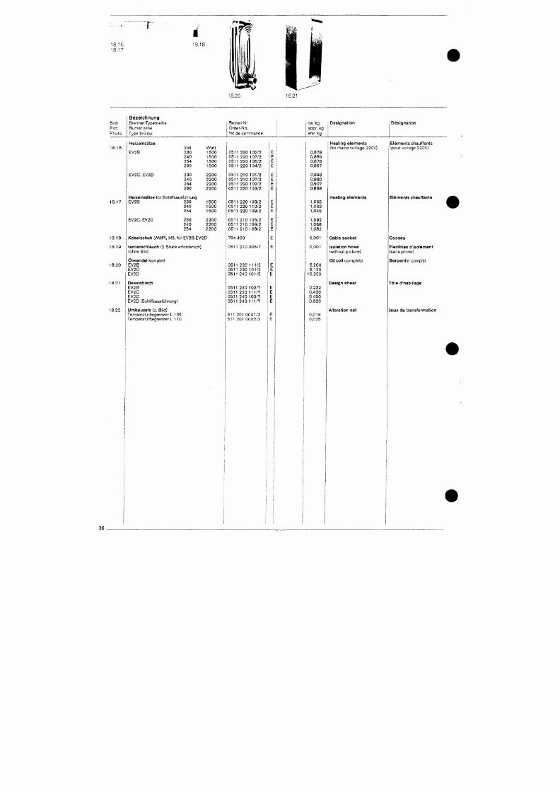
7/18/2019 M14 Thermal Fluid
http://slidepdf.com/reader/full/m14-thermal-fluid 445/486
18.16
18.U
18.21
Bild
Piet.
Photo
Bezeichnung
Brenner-Typenreihe
Burner serie
Type brüleur
Bestell-Nr.
Order-No.
No de commande
j ca. kg
appr. kg
1 env. kg
Designation Designation
18.16
18.17
18.18
18.19
18.20
Heizeinsätze
EV2B
EV2C,
EV2D
Volt Watt
230
1500
240
1500
254
1500
29 0
1500
230
240
254
290
Heizeinsätze für Schiffsausführung
EV2B 230
240
254
EV2C, EV2D
230
240
254
2200
2200
2200
2200
1500
1500
1500
2200
2200
2200
Kabelschuh (AM P), M5, für EV2B-EV2D
Isolierschlauch (2 Stück erforderlich)
(ohne Bild)
Ölwendel komplett
EV2B
EV2C
0511 230 102/2
0511 220 107/2
0511 220 105/2
0511 220 104/2
0511 210 101/2
0511 210 107/2
0511 220 102/2
0511 220 103/2
0511 220 108/2
0511 220 110/2
0511 220 109/2
0511 210 105/2
0511 210 109/2
0511 210 108/2
794 400
0511 210 006/7
0511 220 111/2
0511 230 101/2
0,878
0,889
0,878
0,857
0,893
0,880
0,907
0,868
1,065
1,063
1,045
1,092
1,066
1,082
0,001
0,001
5,200
5,120
Heating elements
(for mains voltage 220V)
j
Elements chauffants
i (pour voltage 220V)
Heating elemen ts Elements chauffants
Cable socket
Isolation hose
(without picture)
Oil coil complete
Cosses
Flexibles d'isolement
(sans photo)
Serpentin complet
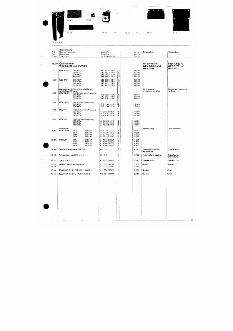
7/18/2019 M14 Thermal Fluid
http://slidepdf.com/reader/full/m14-thermal-fluid 446/486
18.40
18.4:
:S.42 18.43 18,44 8,45
Brid
Piet.
B e z e i c h n u n g
Brenner-Typenre ihe
Bu rne r sene
Photo Type br t j leur
i Beste i i -Nr.
j Orde r -No .
1 No de c o m m a n d e
I oa.
kg
i app r . kg
i env.
kg
Des igna t ion Des igna t ion
18.30
18.31
18 .32
18 .33
18 .35
Ölvorw/ärmer
WEV 2.2/01 und WEV 3/01
W E V 2 . 2 / 0 1 3 8 0 / 4 0 0 V
2 4 0 / 4 1 5 V
2 5 4 / 4 4 0 V
2 9 0 / 5 0 0 V
W E V 3 / 0 1 3 8 0 / 4 0 0 V
2 4 0 / 4 1
5V
2 5 4 / 4 4 0 V
2 9 0 / 5 0 0 V
O l v o r w ä r m e r W E V 2 . 2 / 0 1
und
WE V
3/01
in Sch i f fsaus führung
W E V 2 . 2 / 0 1
(mit
Sch lauchve rsch raubung )
3 8 0 / 4 0 0 V
2 5 4 / 4 4 0 V
2 9 0 / 5 0 0 V
W E V 2 . 2 / 0 1 (mit Sch i f f sve rsch raubung )
3 8 0 / 4 0 0 V
2 5 4 / 4 4 0 V
W E V 3 / 0 1
(mit
Sch lauchve rsch raubung )
3 8 0 / 4 0 0 V
5 1 2
22 0
0 1 0 2 / 0
5 1 2 22 0 3 1 0 2 / 0
5 1 2 22 0 4 1 0 2 / 0
5 1 2 22 0 5 1 0 2 / 0
5 1 2
30 0
0 1 0 2 / 0
5 1 2
30 0
3 1 0 2 / 0
5 1 2
30 0
4 1 0 2 / 0
5 1 2
30 0
5 1 0 2 / 0
5 1 2
225
0 1 0 2 / 0
5 1 2
225
4 1 0 2 / 0
5 1 2
225
5 1 0 2 / 0
5 1 2 229 0 1 0 2 / 0
5 1 2
229
4 1 0 2 / 0
5 1 2
30 5
0 1 0 2 / 0
2 6 , 5 0 0
2 6 , 5 0 0
2 6 , 5 0 0
2 6 , 5 0 0
4 5 , 5 0 0
4 6 , 0 0 0
4 6 , 0 0 0
4 6 , 0 0 0
2 6 , 5 5 0
2 6 , 5 0 0
2 6 , 5 5 0
2 8 , 4 0 0
2 8 . 4 0 0
4 6 , 2 0 0
Oil preheater
WEV 2.2/01 and
WEV 3/01
Oi l p rehea te r
in marine execution
Réchauffeurs
WEV 2.2/01 et
WEV 3/01
Réchauf feur execut ion
marit ime
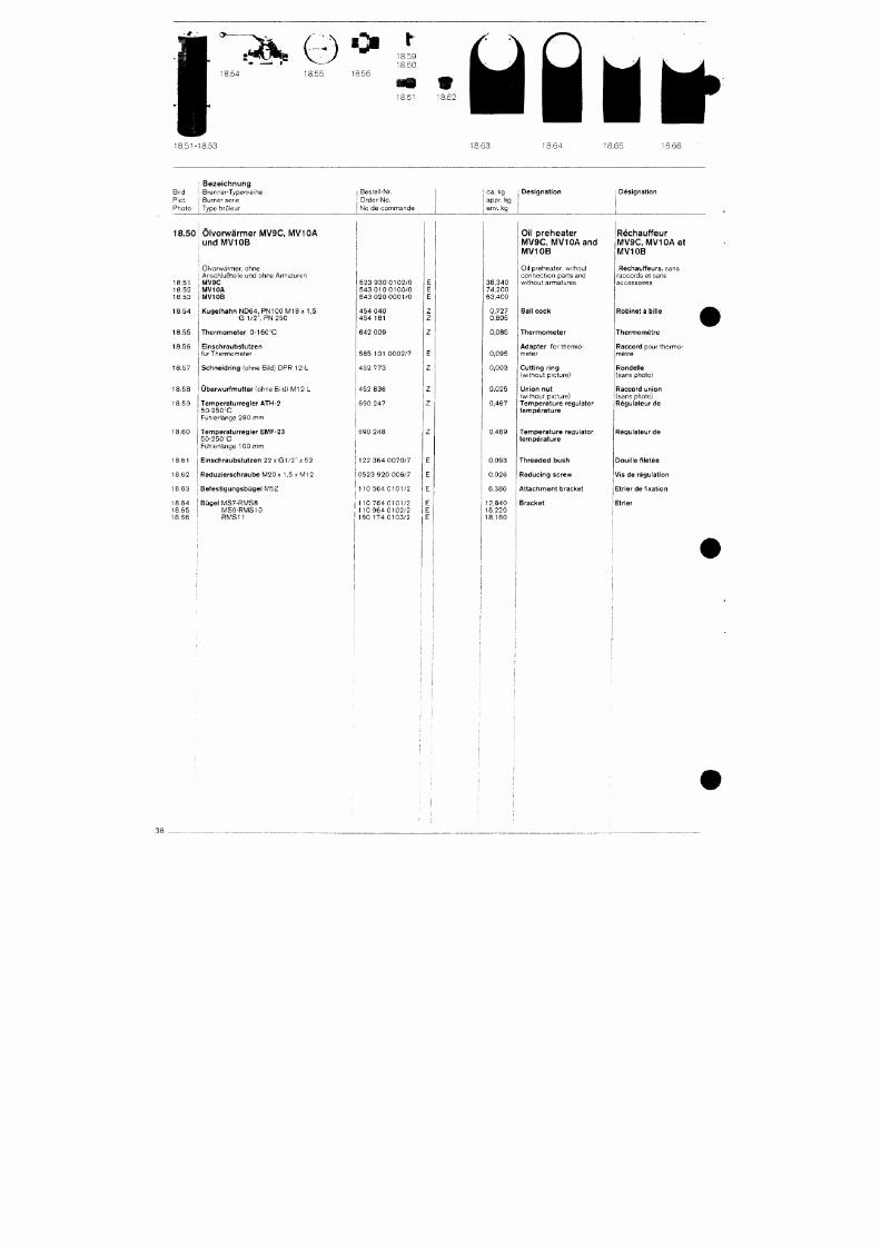
7/18/2019 M14 Thermal Fluid
http://slidepdf.com/reader/full/m14-thermal-fluid 447/486
s*4%t
18.54
18.51-
Bi ld
Piet.
Pho to
18.50
18 .51
1 8 . 5 2
1 8 . 5 3
1 8 . 5 4
1 8 . 5 5
18 .56
18 .57
1 8 . 5 8
18 .59
8,53
B e z e i c h n u n g
Brenne r -Typen re i he
Burner sene
Type brü ieur
Olvorwärmer MV9C, MV I CA
u n d MVIO B
Olvo rwärmer . ohne
Ansch luß te i l e und ohne Arma tu ren
M V 9 C
M V 1 0 A
M V 1 0 B
K u g e l h a h n N D 6 4 , P N 100 M18 x 1 , 5
G 1 /2 " , PN 2 5 0
T h e r m o m e t e r
0-160°C
Einschraubs tu tzen
f ü r The rmome te r
Schne idr ing (ohne Bi ld) DPR 12-L
Ü b e r w u r f m u t t e r ( ohne B i l d ) M I 2 L
Tempera turreg le r ATH-2
5 0 - 2 5 0 C
Füh le r l änge 280 mm
1 Beste l l -Nr.
• Orde r -No .
1 N o d e c o m m a n d e
1I
5 2 3 9 3 0 0 1 0 2 / 0
5 4 3 0 1 0 0 1 0 0 / 0
5 4 3 0 2 0 0 0 0 1 / 0
4 5 4 0 4 0
454 181
6 4 2 0 0 9
5 8 5 1 0 1 0 0 0 2 / 7
4 5 2 7 7 3
4 5 2 8 3 6
690 247
E
E
E
Z
Z
z
E
Z
z
z
18.53
ca. kg
appr. kg
env. kg
3 8 , 3 4 0
7 4 , 2 0 0
6 3 , 4 0 0
0,727
0,805
0,085
0,095
0,003
0,025
0,467
1 8 . 6 4 1 8
D e s i g n a t i o n
Oil preheater
MV9C, MVIOAand
MV10B
Oi l preheater . wi thout
connect i on pa r t s and
wi thou t a rma tu res
Bali cock
T h e r m o m e t e r
A d a p t e r for thermo
meter
Cutt ing ring
(wi thout p icture)
Union nut
(wi thout p icture)
Tempera ture regu la tor
t e m p e r a t u r e
65 18.66
Des igna t ion
iRéchauffeur
MV9C, MVIO Aet
MV10B
Réchauf feurs , sans
racco rds e t sans
accesso i res
Robinet a bi l le A
T h e r m o m é t r e
Raccord pou r t he rmo
mé t re
Ronde l le
(sans photo)
Raccord union
(sans photo)
Régula teur de
f •
1 ^~ "'
T A
,
''nr
' . ,»
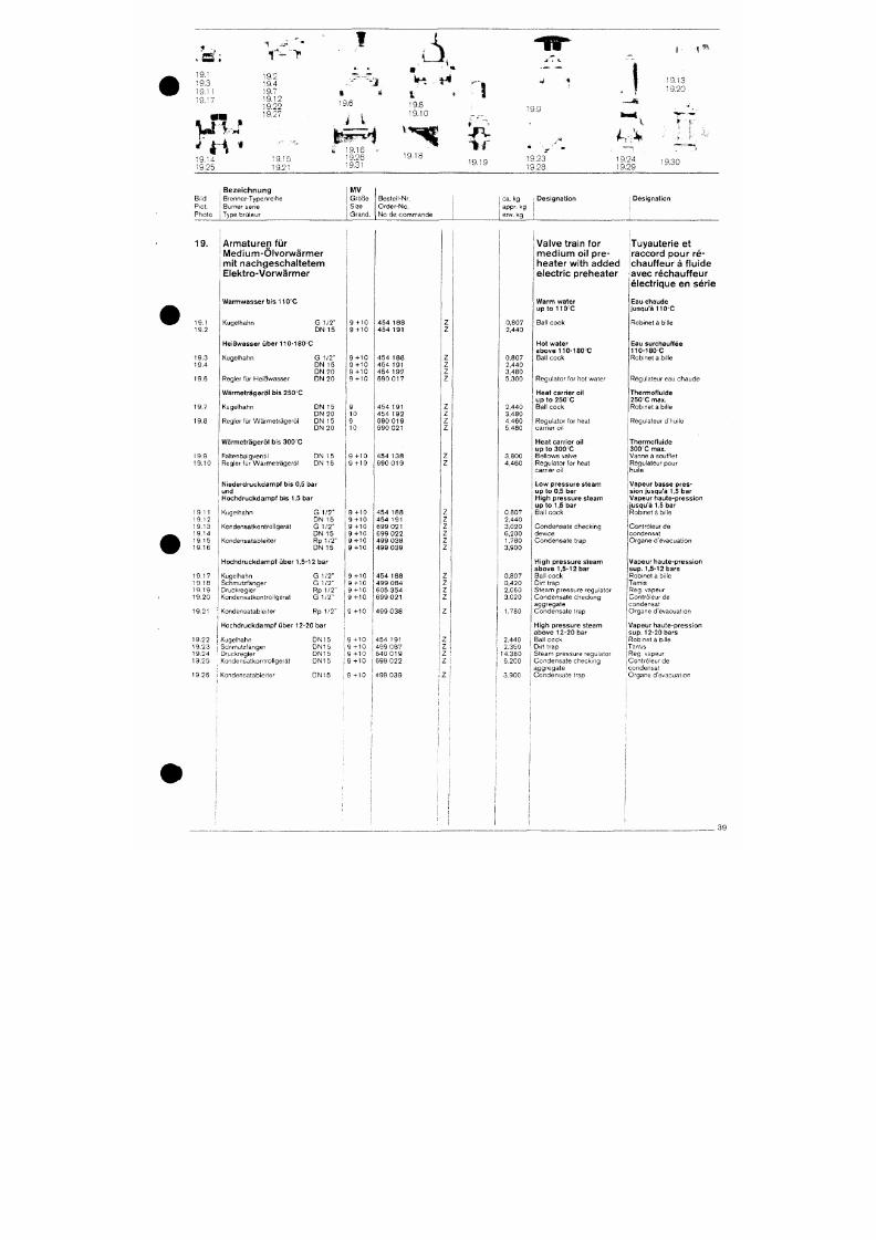
7/18/2019 M14 Thermal Fluid
http://slidepdf.com/reader/full/m14-thermal-fluid 448/486
19.1
19.3
19.1 1
19.17
.
m
% I-
. r-"'y
19.2
19.4
' F o •
19.12 ,q
19.22 ^ ^
B 19.27
M
•
1
a
K
• J ^ - ^ j '^^ r-^ ^.-,
* t
•6 19.8
19.10
1 l
' i % ' » 1 9 1 6
19.14
19.25
Bi ld
PiCt.
P t i o to
19.
19.1
19 .2
19 .3
19 .4
19 .6
19.7
19.8
19.15
19.21
Bezeichnung
Brenne r -Typen re the
Burner ser ie
Type brCileur
Armaturen für
Medium-Ölvorwärmer
mit nachgeschaltetem
Elektro-Vorwärmer
W a r m w a s s e r b i s 1 1 0 ' C
Kugelhahn G 1/2"
DN 15
H e i ßw a s s er ü b er 1 1 0 - 1 8 0 0
Kugelhahn G 1/2"
ON 15
DN 20
Regler für Heißw asse r DN 20
Wärmet rägerö l b is 250=0
Kuge lhahn DN 15
D N 2 0
Reg le r f ü r Wärm e t räge rö l DN 1 5
9.26 ly- iö
9.31
MV
Größe
Size
Grand .
9 - H O
9 - H O
9-1-10
9 - H O
9 - H O
9-1-10
9
10
9
Beste l i -Nr.
O r d e r - N o .
N o d e c o m m a n d e
4 5 4 1 8 8
454 191
4 5 4 1 8 8
454 191
4 5 4 1 9 2
690 Ol 7
454 191
4 5 4 1 9 2
6 9 0 0 1 9
f ""•
* • - « .
4 i
'
39
j
1 19.13
1 19.20
J Ä
\ * 1
1,
1 9 1 9 ' 9 - 3 1 9 .2 4 i q g n
^ • • ^ 1 9 . 2 8 1 9 . 2 9
Z
Z
Z
Z
Z
Z
Z
z
ca . kg
appr. kg
env. kg
0,807
2 ,440
0,807
2 ,440
3,480
5,300
2 ,440
3,480
4 ,460
1 Des igna t ion
i
Valve train for
medium oil pre
heater with added
electric preheater
W a r m w a t e r
u p t o 1 1 0 ' C
Ba l l cock
Hot wa te r
above 110 -180°C
Ba l l cock
Regulator for hot water
Heat carrier oi l
u p t o 2 5 0 ' C
Ba l l cock
Regulator for heat
1
D es igna t ion
1
1
1
iTuyauterie et
raccord pour re-
chauffeur ä fluide
avec réchauffeur
électrique en serie
Eau chaude
jusqu 'å 110 'C
Robinet ä b i l le
Eau surchauf fée
110 -180=C
Robinet ä bi l le
Réguiateur eau chaude
Thermof lu ide
2 5 0 ' C m a x .
Robinet ä b i l le
Réguiateur d 'hu i le
• * > «
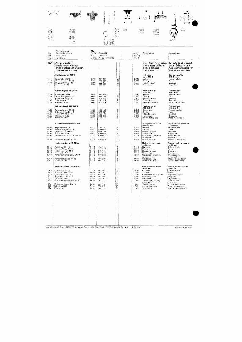
7/18/2019 M14 Thermal Fluid
http://slidepdf.com/reader/full/m14-thermal-fluid 449/486
19.4"
:9.45
•9.55
' 9 .6 '
•0 8 «
19.42
19.46
:9.5 t
19.56
19.62
19.69
.«^
i
'^»<-'
19.44
•9.48
19.53
19.49
19.54
19.67
19.75
19 58
19.64
19.72
^ 9.50
i 9.70
Bezeichnung
B<\ö '
Brenner-Typenreihe
Pict. • Burner sene
Photo Type brCiieur
MV
Größe
Stze
Grand.
Bestell-Nr,
Order-No.
No de commande
i '^3- ^9
i appr. kg
env. k g
Designation Designation
19.45
19.46
19.47
19.48
19.49
19.50
19.51
19.52
19.53
19.40 Armaturen für
I IVledium-Vorwärmer
ohne nachgeschaltetem
; Elektro-Vorwärmer
,
Heißwasser
bis 200 C
19.41 ; Kugelhahn DN 15
19.42 Schmutzfänger DN 15
19.43 Regelventil 15/6 H1F
19.44 Thermostat 4.05
i
Wärmeträgeröl bis 25 0C
Kugelhahn
DN 15
Schmutzfänger
DN 15
Regelventil 15 Hl F
Thermostat 4.05
Kühlstücl(
KS5
Wärmeträgeröl 250-300 C
Faltenbalgventil DN 15
Schmutzfänger
DN 15
Regelventil
15/6 Hl F
Thermostat 4.05
1
9+10
;
9-HO
9-HO
9-HO
9+10
9+10
9+10
9+10
9+10
9+10
9+10
9+10
9+10
1
i
i
454 191
i 4 99 087
60 5 105
69 0 002
454 191
49 9
087
60 5 102
69 0 002
60 5
111
45 4 138
49 9
087
60 5
105
69 0
002
1
i
1
i i
Z
z
z
z
z
z
z
z
z
z
z
z
z
'
2.440
2,350
3,200
3,000
2,440
2,350
3.100
1 3.000
\
0,600
3,800
2,350
i
3,200
3,000
1
Valve train
for
medium
i preheaters withou t
1 added electric
i preheater
Hot water
up
to 200 C
Ball cock
Dirt trap
Regulating valve
Thermostat
Heat carrier oil
up to 250 C
Ball cock
Dirt trap
Regulating valve
Thermostat
Intermediate piece
Heat carrier oil
250-300 C
Sipon valve
Dirt trap
Regulating valve
Thermostat
Tuyauterie
et
raccord
pour réchauffeur ä
fluide sans réchauf fer
électrique en serie
Eau surchauffée
2 0 0 0
max.
Robinet
ä
bille
Tamis
Soupape
Regulateur
Thermofluide
250'C max.
Robinet
ä
biüe
Tamis
Soupape
Regulateur
Piece intermedlaire
Thermofluide
250-300 C
Vanne a souffiet
Tamis
Soupape
Regulateur
weishaupt

7/18/2019 M14 Thermal Fluid
http://slidepdf.com/reader/full/m14-thermal-fluid 450/486
f
^
manual
Installation and operating instruction
Contents
1
1 General instructions
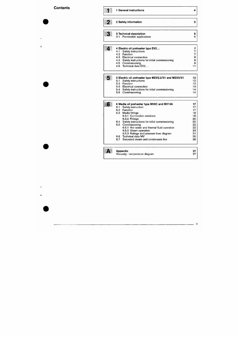
7/18/2019 M14 Thermal Fluid
http://slidepdf.com/reader/full/m14-thermal-fluid 451/486
2 Safety information
3 Technical description
3.1 Permissible applications
4
4 Electric oil preheater type EV 2. . .
4.1 Safety instruct ions
4.2 Funct ion
4.3 Electr ica l con nec t ion
4.4 Safety instruct ions for init ial commissioning
4 .5 Commiss ion ing
4.6 Technical data EV 2.. .
7
7
7
8
9
9
11
5
5 Electric oil preheater type WE V2.2 /01 and WE V3/ 01
5.1 Safety instruct ions
5.2 Function
5.3 Electr ica l conn ect ion
5.4 Safety instruct ions
for
init ial commissioning
5.5 Commissioning
12
12
12
13
14
14
6
6 Media oil preheater type MV9C and MV1 OA
6.1
6.2
6.3
Safety instruct ion
Funct ion
Media f i t t ings
17
17
17
18
General instructions
Th ese installation and operating instructions Hand over and operating instructions
7/18/2019 M14 Thermal Fluid
http://slidepdf.com/reader/full/m14-thermal-fluid 452/486
• are an integral part of the equipm ent and must be kept
permanently on site.
• are to be used by qualif ied personn el only.
• con tain the relevant information for the safe assembly,
comm issioning and servicing of the equipme nt.
• are for the attentio n of al l personnel workin g with the
equipment.
Explanation of notes and symbols
This symbol is used to mark instructions,
which,
i f not fol lowed, could result in death or
serious injury.
DANGER
A
DANGER
A
ATTENTION
This symbol is used to mark instructions,
which,
i f not fol lowed, could result in l i fe
threatening electr ic shock.
This symbol is used to mark instructions,
which, i f not fol lowed, could result in damage
to , or the destruct ion of the equipment and
environmental damage.
The contractor is responsib le for passing the operat ing
instructions to the plant operator pr ior to hand-over. He
should also inform the plant operator that these
instruct ions shou ld be kep t wi th the heat ing appl iance. The
address and telephone number of the nearest service
centre should be entered on the reverse of the operating
instructions. The plant operator must note that an agent of
the contractor or other suitably qualif ied person must
inspec t the plant at least onc e a year. To ensure regular
inspect ions, -weishaupt- recomm ends a service contract.
The contractor should instruct the plant operator in the use
of the equipment pr ior to hand-over and inform him as and
when necessary of any further inspections that are
required before the plant can be used.
Guarantee and liability
Weishaupt wil l not accept l iabil i ty or meet any guarantee
claims for personal injury or damage to property ar ising as
a result of one or more of the caus es b elow :
Failure to use the equipment as intended
Improper assembly, commissioning, op erat ing or
servicing of the equipment.
Ope rat ing the appl iance w i th defective safety
equipment, or wi th non-recommended or non
funct ioning safety and protect ion devices
Failure to fol low the information in the Instal lation and
Operat ing Instruct ions
Al terat ions made to the construct ion of the equipment
by the plant operator
Fi t t ing addi t ional components not tested or approved
for use wi th the equipment.
2 Safety information
Dangers when us ing the equipment
Elect r i ca l
safety
7/18/2019 M14 Thermal Fluid
http://slidepdf.com/reader/full/m14-thermal-fluid 453/486
Weish aupt products are manufactured in accordance wi th
the relevant existing standards and guidelines and the
recognised safety laws. However , improper use of the
equip men t cou ld endan ger l i fe of the user or a third party,
or result in damage t o the plant.
To avoid unnecessary danger, the equipment is only to be
used:
• for i ts intended purp ose
• under ideal safety con ditio ns
• with reference to ai l the information in the instal lation
and operat ing instruct ions
• in acc orda nce with inspec tion and service woric
Faults, which could affect the safe operation of the burner,
should be rectif ied immediately.
Personnel training
Only com petent personnel m ay work on the appl iance.
Com peten t personnel acc ord ing to th is operat ing manual
are persons who are famil iar with the instal lation,
mount ing ,
sett ing and comm issioning of the product and
have the necessary qual i f icat ions s uch as:-
• Training, instruction or authorisation to sw itch electr ical
circuits and electr ical devices on and off, to earth them
and to mark them in accordan ce w i th the safety
standards.
Organisational measures
• Everyone working on the plant sho uld we ar the
necessary protect ive cloth ing.
• All safety devices sh oul d be chec ked regularly.
• Befo re starting work - isolate plant and prote ct
against reactivation, check voltage is isolated, the unit
is ear thed, and protected from adjacent equipment
that might sti l l be under voltage
• W ork on the electr ical sup ply shou ld be carr ied out by
a qualif ied electr ician.
• Electr ica l comp onents shou ld be check ed dur ing
serv ic ing.
Loose connect ions and heat damaged
cables should be dealt with immediately.
• The con trol panel sho uld be locked at al l t ime s.
Access should be restr icted to author ised key holder
personnel .
• Sh ould it be necessary to carry out wo rk on l ive parts,
country specific safety regulations must be observed
and too ls to EN 609 00 must be used . A second
person should be present to swi tch off the mains
supply in an emergency.
iVIaintenance and fault rectification
• Allo w the unit to cool pr ior to servicing and
maintenance work to avoid injury through high
temperatures.
• Necess ary insta l la t ion, service and inspect ion work
should be carr ied out at the spec i f ied t ime.
• Inform the operator befo re beginn ing any service work.
• For al l service, inspec tion and repair work , electrically
isolate the equipment and ensure the mains switch
cannot be accidenta l ly swi tched back
o n .
Cut off the
fuel supply.
• If, durin g servicing or tes ting , contro l seal joints have to
be open ed, these have to be thoroughly cleaned to
ensure tight sealing when re-assembling.
Dam aged seals must be replaced. Carry out a
3 Technical description
On burners for use with medium and heavy residual fuel

7/18/2019 M14 Thermal Fluid
http://slidepdf.com/reader/full/m14-thermal-fluid 454/486
oils the oil has to be preheated to the temperature required
for atomisation.
Oil preheating can be carr ied out electr ically or with
heat ing m edium, as we l l as wi th a combinat ion of e lectr ic
and me dia heaters. Ho t water, low and high pressure
stea m or thermal f luid oi l are used as h eating me dia.
3.1 Permissible applications
We ishaupt o i l preheaters are sui table:
• for residual fuel oi ls :
In their standa rd version for a visco sity up to
50 mm^/s at 100°G (approx. 570 mm^/s at 50°G)
In specia l versions for a viscosity o f up to
60 mm^/s at 10 O' C (approx. 700 m mV s at 50°C)
• for instal lation on W eishau pt med ium and heavy
residual oi l burners
• for a maximum oil tempe rature of 160 ° C
Any other application is only permitted with pr ior written
agreement o f Max Weishaupt G mb H.
The oil preheater must only be used within the ratings
given on the name plate.
The oil preheater is not suitable for operatio n out of
doors.
The oil preheater must not be operated outside of i ts
permit ted temp erature range.
4 Electric oil preheater type EV2.
4.1 Safety instructions
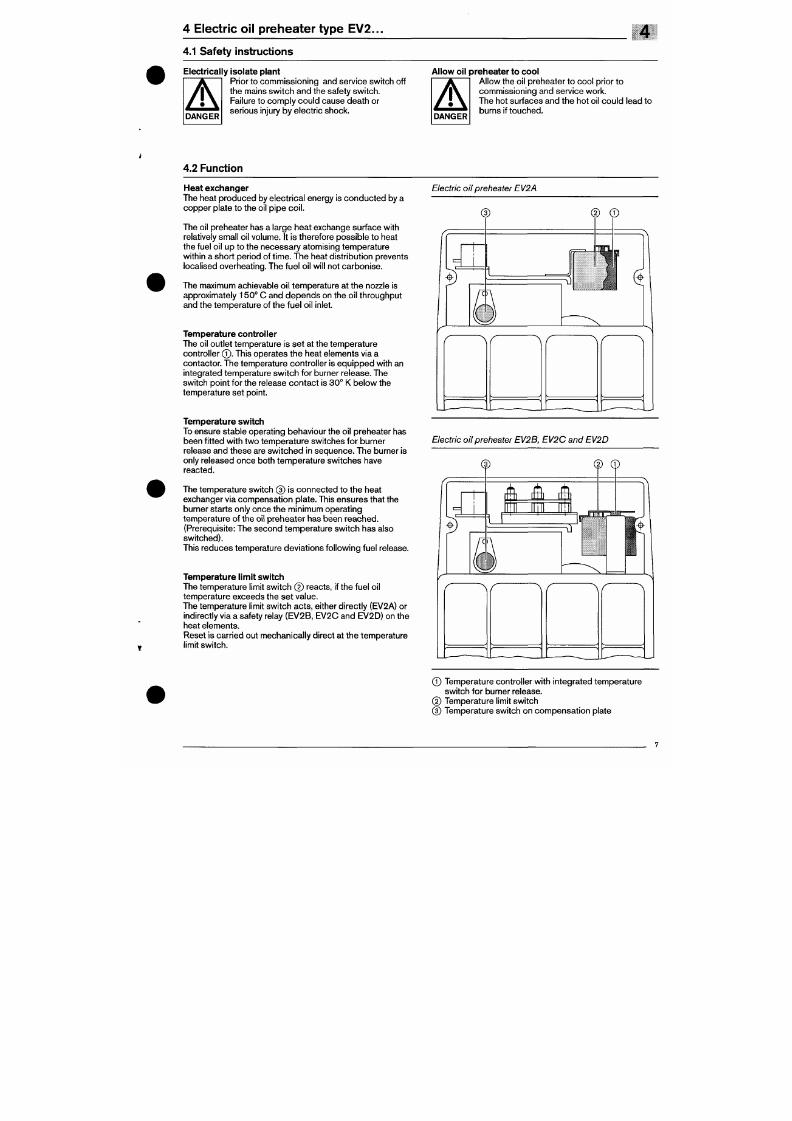
7/18/2019 M14 Thermal Fluid
http://slidepdf.com/reader/full/m14-thermal-fluid 455/486
Electrically isolate plant
T T
I Prior to com mis sionin g and service switc h off
X j \ the mains sw i tch and the safety sw i tch.
X J \ Failure to com ply co uld cause dea th or
^ ^ ™ "
serious injury by electr ic shock.
Allow oil preheater to cool
T T
I Allow the oil preheater to coo l pr ior to
# l \ commiss ion ing and serv ice work.
X J \ The hot surfaces and the hot oi l co uld lead to
" ^ ^ " burns if to uc he d.
4.2 Function
Heat exchanger
The heat produ ced by e lectr ica l energy is cond ucte d by a
copper plate to the oil pipe
coi l .
The oil preheater has a large hea t exchange surface with
relatively small oil volume. It is therefore possible to heat
the fuel oi l up to the necessary atomising temperature
within a short p eriod of t ime . The heat distr ibution prevents
localised overhe ating. The fuel oi l wil l not carb onise .
The maximum achievable oi l temp erature at the nozzle is
approximately 150° C and depends on the oil throughput
and the tem perature of the fuel o i l inlet.
Temperature controller
The oil outlet temperature is set at the temperature
control ler © . This operates the heat elements via a
contactor . The temperature contro l ler is equ ipped wi th an
integrated temperature switch for burner release. The
Electric oil preheater EV2A
4.3 Electrical connection
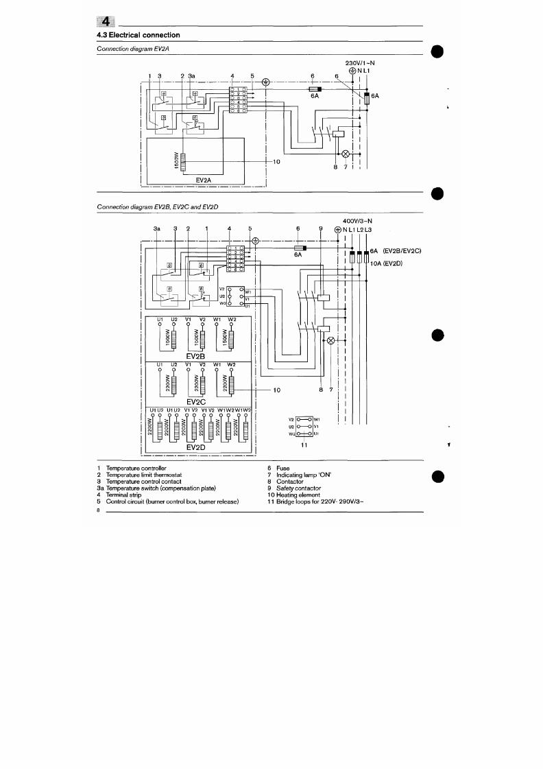
7/18/2019 M14 Thermal Fluid
http://slidepdf.com/reader/full/m14-thermal-fluid 456/486
Connection diagram EV2A
1 3 2 3 a
I I
Col
mj[f^
I
5 ^
o
EV2A
4 5
- I 1 ^
2 3 0 V/1 ~N
© N L 1
o 1 o
o 2 o
O 3 O
O 4 O
O S O
O 6 O
— X J I
6A
-10
I
I
[ 1
v^
^
8 7
6A
Connection diagram EV2B, EV2C and EV2D
4 0 0 V / 3 ~ N
6 9 © N LI L2 L3
-4
6 A ( EV2 B/EV2 C)
4.4 Safety instructions for init ial connmissioning
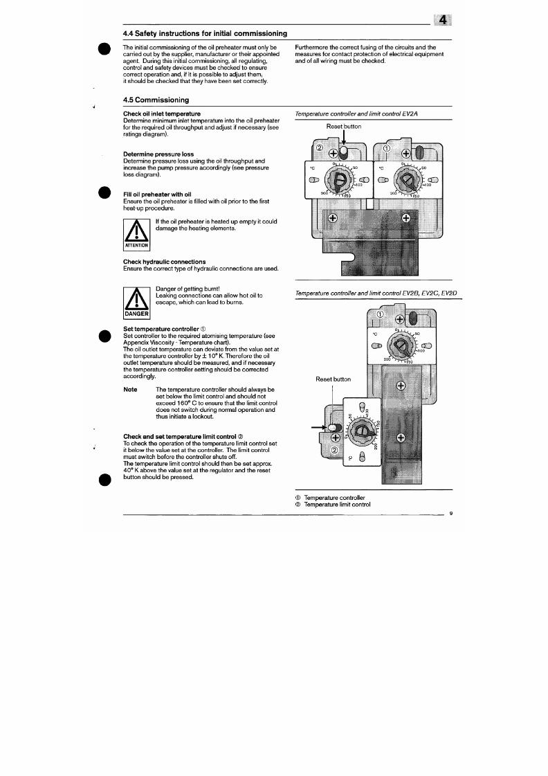
7/18/2019 M14 Thermal Fluid
http://slidepdf.com/reader/full/m14-thermal-fluid 457/486
The init ial commissioning of the oil preheater must only be
carr ied out by the supplier, manufacturer or their appointed
agent. During this init ial commissioning, al l regulating,
contro l and safety devices must be checked to ensure
correct operation and, i f i t is possible to adjust them,
it should be checked that they have been set correctly.
Furthermore the correct fusing of the circuits and the
measures for conta ct protect ion of e lectrica l equipm ent
and of al l wir ing must be checked.
4.5 Com nnissioning
Check oil inlet temp erature
Determine minimum inlet temperature into the oil preheater
for the required oil throughput and adjust i f necessary (see
ratings diagram).
Determine pressure loss
Determine pressure loss using the oil throughput and
increase the pump pressure accordingly (see pressure
loss diagram).
Fill oil prehe ate r with oil
Ensure the oil preheater is f i l led with oi l pr ior to th e first
heat-up proc edure.
If the oil preheater is heated up emp ty it cou ld
damag e the heat ing e lements.
Check hydraulic connections
Temperature controller and limit control EV2A
Reset button
Ratings diagram EV2...
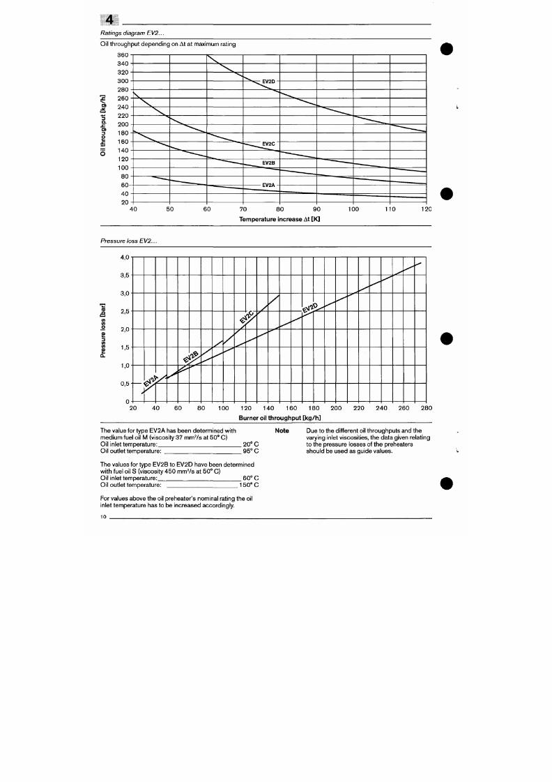
7/18/2019 M14 Thermal Fluid
http://slidepdf.com/reader/full/m14-thermal-fluid 458/486
Oil throughput depen ding on At at maximum rat ing
360
340
320
300
280
2 260
240
220
200
180
160
140
120
100
8 0
6 0
4 0
20
S
3
Q.
I
-
^*^^^EV2D
'-...,,..,^EV2C
. ^ ^ ^ E V 2 B
' - ^ — - ^
40 50 60 70 80 90
Temperature increase At [K]
100 110 120
Pressure loss EV2.
4,0
4 .6 T ech n ica l d a t a E V 2 .
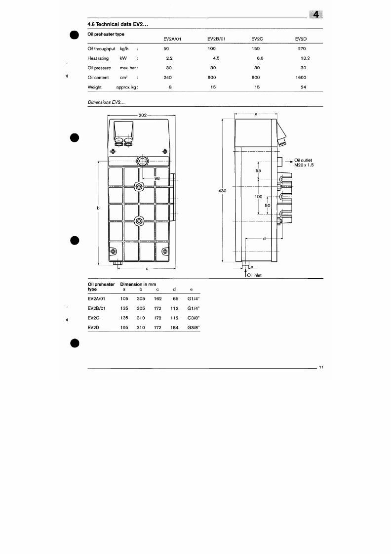
7/18/2019 M14 Thermal Fluid
http://slidepdf.com/reader/full/m14-thermal-fluid 459/486
Oil preheater type
EV2A/01
EV2B/01
EV2C EV2D
Oil throughput
Heat rating
Oil pressure
Oil content
Weight
kg/h
k W
max. bar:
cm ^
:
approx. kg:
5 0
2.2
3 0
240
8
1 0 0
4.5
3 0
8 0 0
1 5
1 5 0
6.6
3 0
8 0 0
15
270
13.2
3 0
1 6 0 0
2 4
Dimensions EV2.
202
9 8 -
5 5
_ ^ Oil outlet
_ l M 20x1 .5
&
5 Electric oil preheaters type W EV 2.2/0 1 and W EV 3/0 1
5.1 Safety instructions
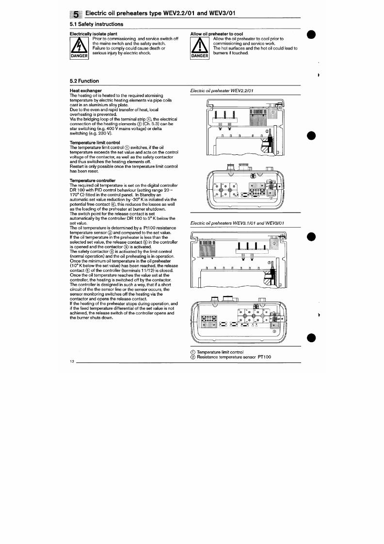
7/18/2019 M14 Thermal Fluid
http://slidepdf.com/reader/full/m14-thermal-fluid 460/486
Electrically isolate plant
Æ
Pr ior to comm issioning and service sw i tch off
the mains swi tch an d the safety swi tc h.
Failure to comply could cause death or
' serious injury by elec tr ic shock.
Allow oil preheater to cool
^ T
I Allo w the oil preheater to coo l pr ior to
X l \ comm issioning and service work.
^ ^ \ The hot surfac es and the hot oi l cou ld lead to
^ ^ • ^ " b urn er s if t ou c he d .
5.2 Function
Heat exchanger
The heating oil is heated to the required atomising
temperature by electr ic heating elements via pipe coils
cas t in an aluminium alloy plate.
Due to the eve n and rapid transfer of heat, local
overheating is prevented.
Via the bridging loop of the terminal str ip @, the electr ical
connection of the heating elements (5) (Ch. 5.3) can be
star swi tch ing (e.g. 40 0 V ma ins vol tage) or del ta
switch ing (e.g. 23 0 V) .
Temperature limit control
The tempera ture l imit contro l Q sw itches , i f the oil
temperature exceeds the set va lue and acts on the con tro l
vo l tage of the contactor , as wel l as the safety con tactor
and thus switc hes the heat ing e leme nts off .
Restart is only possible once the temperature l imit control
has been reset.
Temperature controller
Electric oil preheater WE V2.2/01
5.3 Electrical conn ection
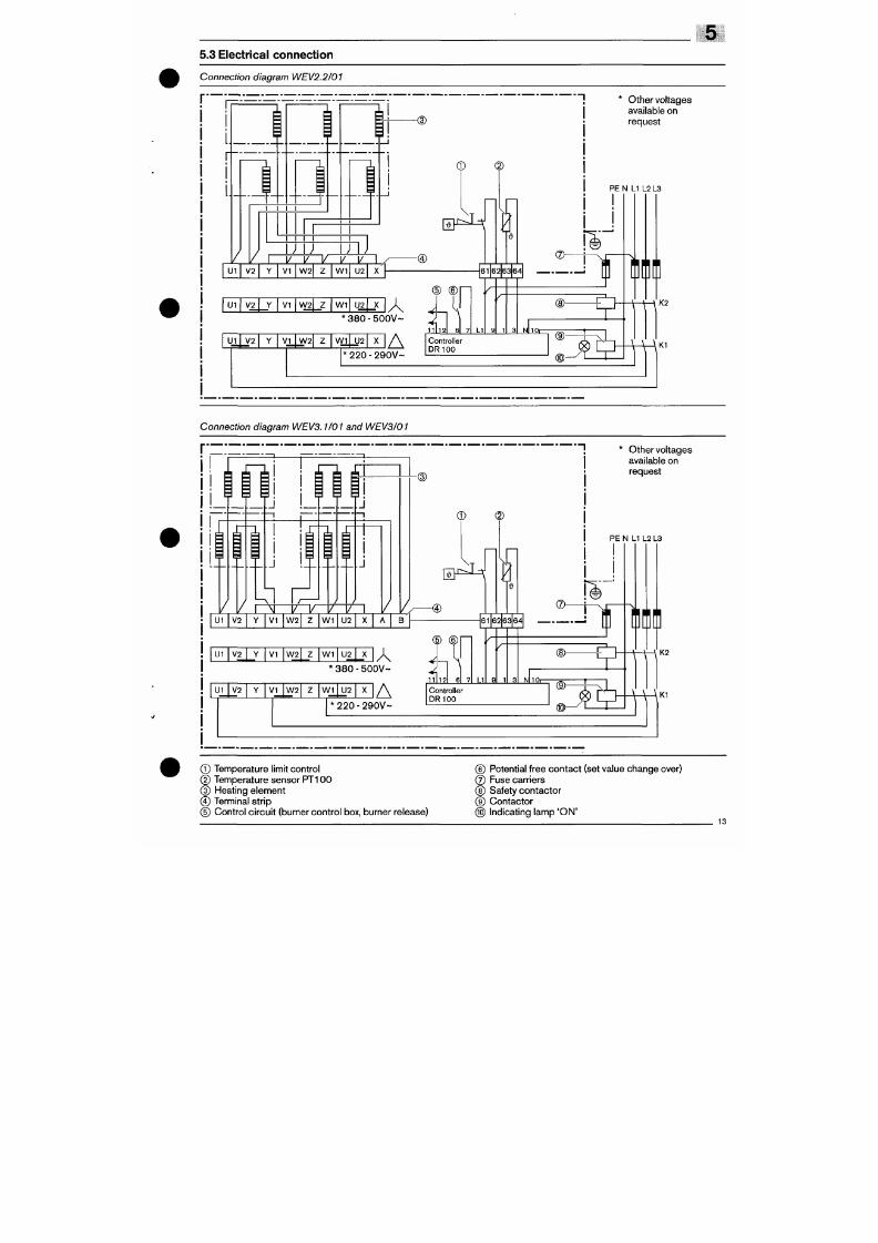
7/18/2019 M14 Thermal Fluid
http://slidepdf.com/reader/full/m14-thermal-fluid 461/486
Connection diagram WE V2.2/01
r
U1
I I I I
K-n
V 2
Z
V I
I I
T71J
®
U : : ^
^
W . V. V.
I
W 2
W 1
U2
-®
61
U1
V 2
V I V\ /2
W 1
U2
U1
V 2 V I
W 2
3 8 0 - 5 0 0 V ~
J
W 1
U2
3 A
20 - 290V -
61 7
, ^
LI
62
^
63 64
® '
Other vol tages
available on
request
PE N LI L2 L3
—
• • w
®-
l O r -
Controller
DR100
^
f i f i n
K2
W\^'
5.4 Safety instructions for init ial commissioning
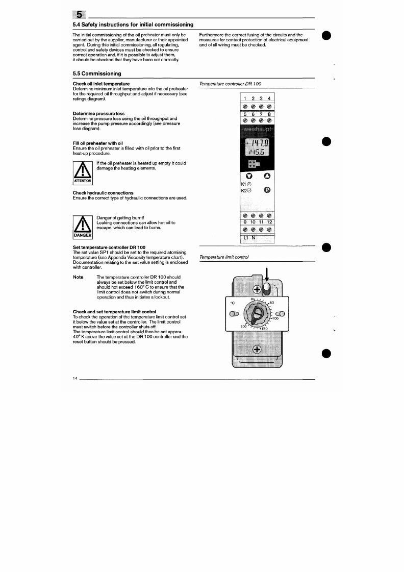
7/18/2019 M14 Thermal Fluid
http://slidepdf.com/reader/full/m14-thermal-fluid 462/486
The initial com miss ioning of the o il preheater mu st only be
carr ied out by the supplier, manufacturer or their appointed
agent. During this init ial com mis sion ing, all regulating ,
contro l and safety devices must b e checked to ensure
correct operation and, i f i t is possible to adjust them,
it should be checked that they have been set correctly.
Furthermore the correct fusing of the circuits and the
measures for contac t protec t ion of e lectr ica l e quipment
and of ai l wir ing must be checked.
5.5 Co mm issioning
Chec k oil inlet tem perature
Determine minimum inlet temperature into the oil preheater
for the required oil throug hput an d adjust if necessary (see
ratings diagram).
Determine pressure loss
Determine pressure loss using the oil throughput and
increase the pum p pressure accordingly (see press ure
loss diagram).
Fill oil preheate r w ith oil
Ensure the oil preheater is f i l led w ith oi l pr ior to the first
heat-up procedure.
If the oil preheater is heated up empty it could
damag e the heat ing e lements.
Chec k hydraulic conn ections
Temperature controller D R 100
1
0
5
@
2
e
6
9
3
e
7
®
4
e
8
e
O o
K1 @
K 2 @
Ratings diagram WE V..
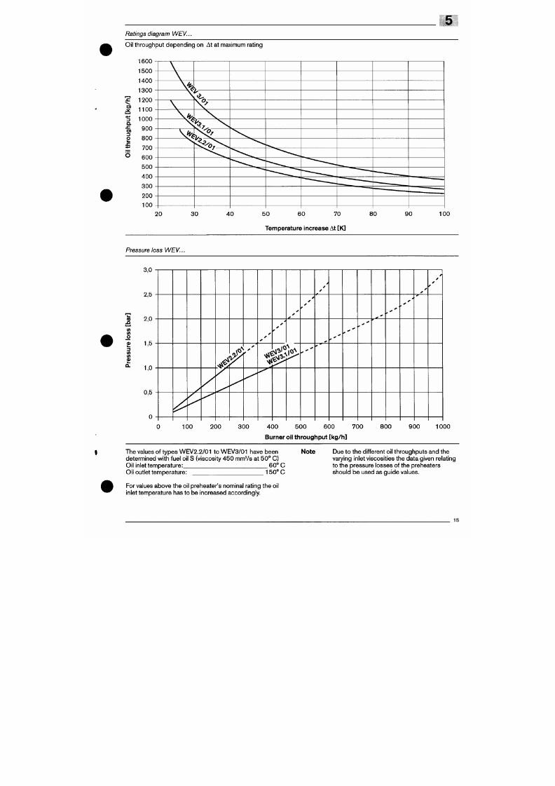
7/18/2019 M14 Thermal Fluid
http://slidepdf.com/reader/full/m14-thermal-fluid 463/486
Oil throughput dependin g on At at maximum rat ing
1600
1500
1400
1300
1200
S
1100
3
a.
I
1000
900
800
700
600
500
400
300
200
100
\ ^ .
\ %
*v
V
% f,
\
V-^IS?'
F^t^>^
"
20 30 40 50 60 70 80 90 100
Temp erature increase At [K]
Pressure loss WEV...
Oil preheater type
WEV2.2/01
WEV3.1/01
WEV3/01
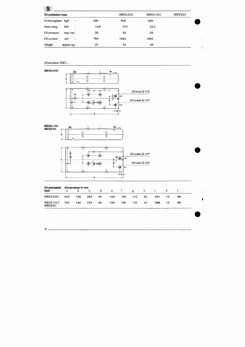
7/18/2019 M14 Thermal Fluid
http://slidepdf.com/reader/full/m14-thermal-fluid 464/486
Oil throughpu t kg/h
Heat rating kW
Oil pressure max. ba r:
Oil con tent cm^
Weight approx. k g :
3 0 0
13.8
3 2
750
27
5 0 0
170
3 2
1 5 5 0
4 2
5 0 0
22.4
3 2
1 5 5 0
4 2
Dimensions
WEV...
WEV2.2/01
I nff
L
Ä
w
^
ro
- i - i > i
-@>-
r -
_f._
i_.
M 10 I
J ^
wU
L
O i l i n l e t G I / 2 "
Oil outlet G 1/2"
6 Media oil preheaters type MV9C and
MV1 OA
6.1 Safety instructions
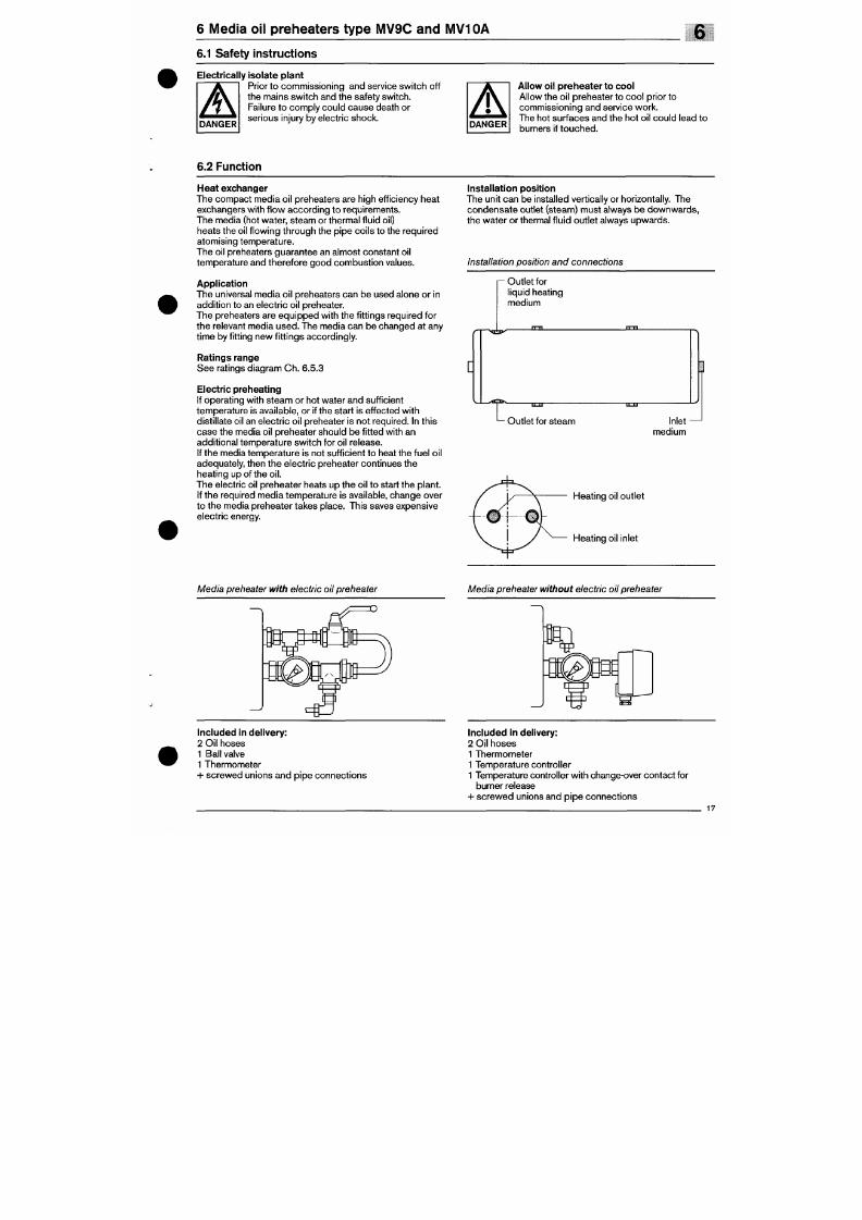
7/18/2019 M14 Thermal Fluid
http://slidepdf.com/reader/full/m14-thermal-fluid 465/486
Electrically isolate plant
^ ^ I Pr ior to comm issioning and service sw i tch off
^ j \ the mains swi tc h and the safety swi tch.
X t \ Failure to com ply cou ld caus e death or
" ^ ^ ^ s er io u s in ju ry b y e le ct ri c s h oc k .
Allow oil preheater to cool
Allow the oil preheater to cool pr ior to
comm issioning and service work.
The hot surfaces and the hot oi l could lead to
burners if touched.
6.2 Function
Heat exchanger
The compact media oi l preheaters are high efficiency heat
exchangers wi th f low acco rding to requirements.
The media (hot water, ste am or therm al f luid oil)
heats the oil f lowing through the pipe coils to the required
atomising tempe rature.
The oil preheaters guarantee an almost constant oi l
temperature and therefore good com bust ion values.
Application
The universal media oi l preheaters ca n be use d alone or in
additio n to an electr ic oi l preheater.
The preheaters are equipped with the fi tt ings required for
the relevant media used. The media can be changed at any
time by fi tt ing new fitt ings accordingly.
Ratings range
See rat ings d iagram C h. 6.5.3
Electric preheating
If operating with steam or hot water and sufficient
temp erature is available, or i f the start is effected wit h
Installation position
The unit can be installed vertically or horizontally. The
condensate out le t (steam) must a lways be downwards,
the water or thermal f luid outlet always upwards.
Installation position and connections
Outlet for
l iquid heating
medium
6.3 Media fitt ings
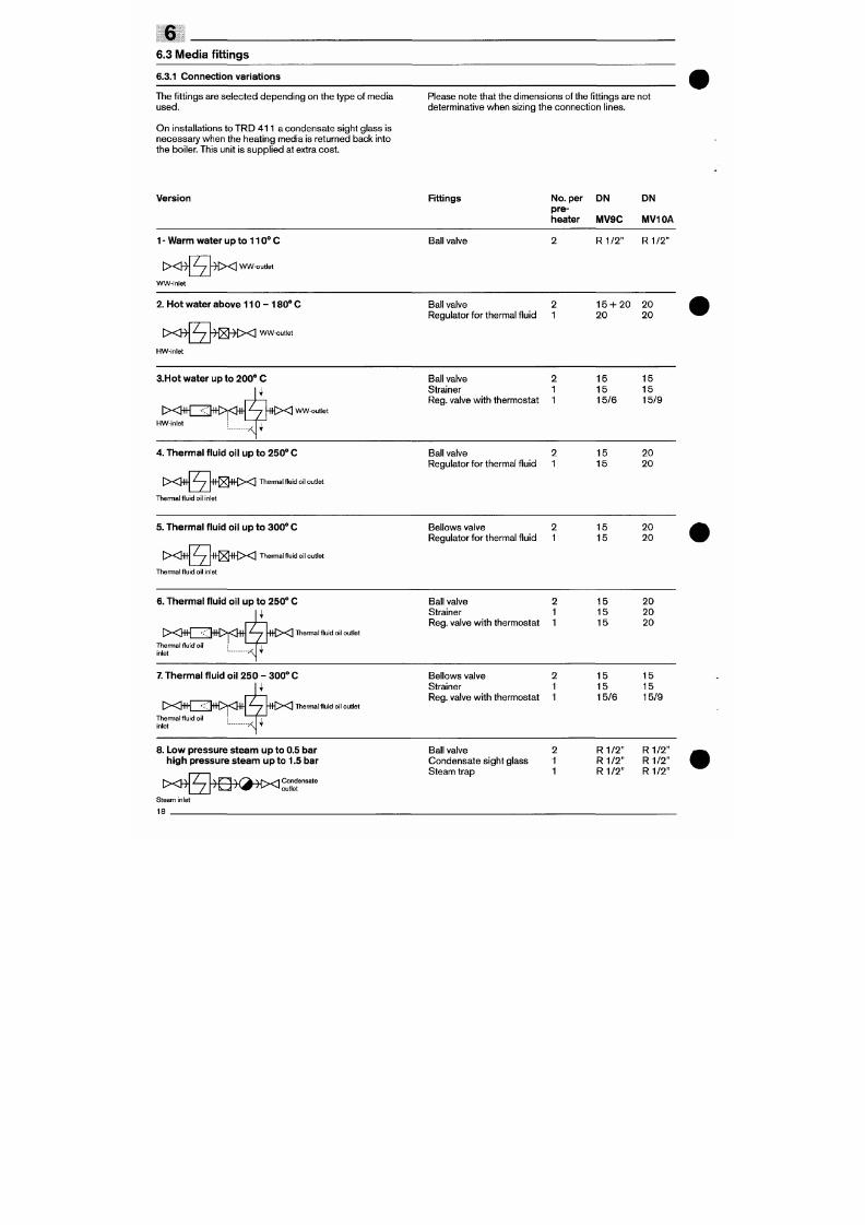
7/18/2019 M14 Thermal Fluid
http://slidepdf.com/reader/full/m14-thermal-fluid 466/486
6.3.1 Connection variations
The f i t tings are selected de pending on the type of media
used.
On instal lations to TR D 4 1 1 a condensate sight g lass is
necessary when
the
heat ing media
is
returned back into
the boiler. This unit
is
supp l ied
at
extra co st.
Please note that the d imensions of the fi tt ings are not
determinative when sizing the connection l ines.
Version
Fittings
No. per DN DN
pre-
heater IVIV9C MV10A
1 - Warm water up to 1 1 0 ° C
I X B -
^
f ^ i X WW-outlet
Z
W-inlet
Ball valve
R 1 / 2 " R1/2"
2. Hot water above 110 - 1 8 0 ° C
I X B -
^
^ i ^ ^ X
WW-outlet
HW-inlet
Ball valve
2 15 + 20 20
Regulator for thermal f luid
1
20 20
3.Hot
wa te r up to 200"* C
[ > < H H ~ < H H > < } t t
'—7 - H t x
WW-outlet
Ball valve 2
Strainer
1
Reg. va lve wi th thermostat
1
1 5
1 5
15/6
1 5
1 5
15/9
Version Fittings
No. per
pre
D N
6
DN
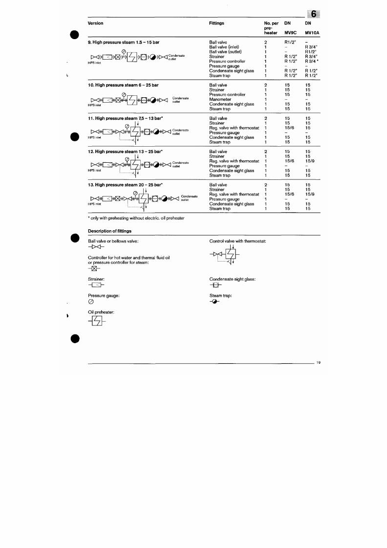
7/18/2019 M14 Thermal Fluid
http://slidepdf.com/reader/full/m14-thermal-fluid 467/486
heater
M V 9 C
IVIV10A
9.
High pressure steam 1.5
-
1 5 b ar
H PS inlet
z
z
\ K >l
\f'~^
\ t ^ ^ Condensate
' outlet
Ball valve
Ball valve (inlet)
Ball valve (outlet)
Strainer
Pressure control ler
Pressure gauge
Condensate sight g lass
Steam trap
R 1/2 "
R 1 / 2 "
R 1 / 2 "
R 1 / 2 "
R 1 / 2 "
R 3 /4 "
R 1/2 "
R 3 /4 "
R 3 / 4 "
R 1 / 2 "
R 1 / 2 "
10 . H ig h p r es s ur e s te a m 6 - 2 5 b ar
• T . / , , ^ ~ ^ 1 1 / ^ ^ i i i ^ ^ C on den sa te
outlet
H PS Inlet '— ^— '
Ball valve
Strainer
Pressure control ler
Manometer
Condensate sight g lass
Steam trap
15
15
15
15
15
15
15
15
15
15
11 . High pressure s team 7,5 - 1 3 bar*
9
l><JfOlHH><KH+
PS inlet
7
I / ^ M | ^ ^ ^ Condensate
outlet
Ball valve
Strainer
Reg. valve with thermostat
Pressure gauge
Condensate sight g lass
Steam trap
15
15
15/6
15
15
15
15
15
15
15
12 . High pressure steam 13
-
25 bar *
ixWI<WYiJ»|^[*H<K^«tx
SS
HPS inlet
Condensate
Ball valve
Strainer
Reg.
valve with thermostat
Pressure gauge
Condensate sight g lass
Steam trap
15
1 5
1 5 /6
15
15
15
15
15/9
15
15
13. High pressure steam 20 - 25 bar * Ball valve
15 15
6.3.2 Fittings
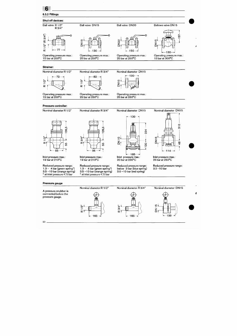
7/18/2019 M14 Thermal Fluid
http://slidepdf.com/reader/full/m14-thermal-fluid 468/486
Sliu t off devices:
Bal l va lve R 1 /2 "
R 3 /4 "
CO
01
w t
Q :
77
Ope rat ing pressure max.:
1 5 b a r a t 2 0 0 * C
Bal l va lve DN 15
Operating pressure max.:
25 bar at 250*'G
Bal l va lve D N 20
°' ,1
CM
2
Q *
ft^r~
1 5 0 -
Operating pressure max.:
25 bar at 250' 'G
Bel lows valve DN15
in*
°r
i n
a
-r^X^
- 1 3 0 -
Operating pressure max.:
1 3 b a r a t 3 0 0 ° C
Strainer:
Nominal diameter R 1
1T
CM
L
«—72 >
^ \ \ ^
Nominal d iameter R 3/4"
- 8 2 -
Nominal d iameter DN 15
in i L
nj ij
Ope rat ing pressure max.:
15 bar at 200''G
Operating pressure max.:
25 bar at 250°C
Operating pressure max.:
25 bar at 250' 'C
P ressure controller:
Nominal d iameter R 1 / 2 " Nominal d iameter R 3/4" Nominal d iameter DN 15
Nominal d iameter D N 15
Control valve:
Nominal d iameter DN20
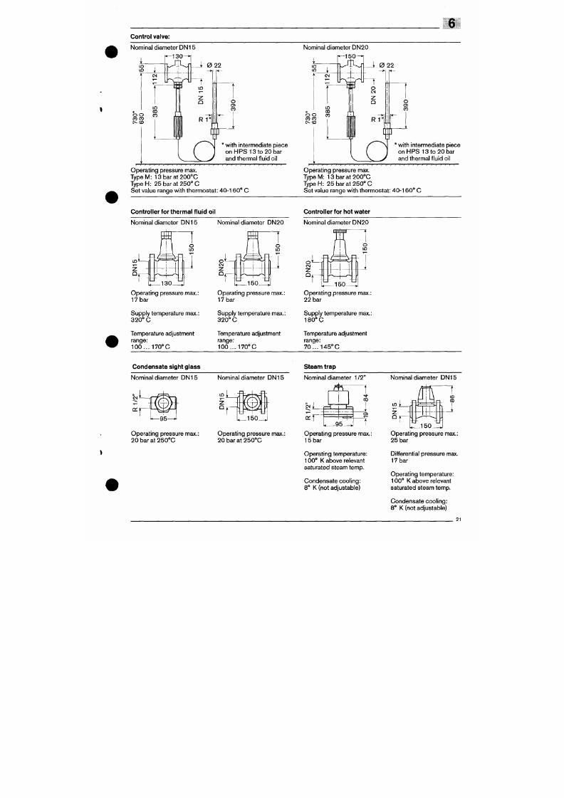
7/18/2019 M14 Thermal Fluid
http://slidepdf.com/reader/full/m14-thermal-fluid 469/486
Nominal d iameter DN15
130
L
in
i 0 22
with intermediate piece
o n H P S 1 3 t o 2 0 b a r
and therm al f luid oi l
Operating pressure max.
T y p e M :
1 3 b a r a t 2 0 0 ° C
T y p e H : 25 bar at 250° C
Set va lue range wi th thermostat : 40-160" C
- 1 5 0 - ^
L
in
i 0 22
with intermediate piece
on HPS 13 to 20 bar
and therma l f luid oi l
} } I I }
Operating pressure max.
T y p e M :
13 bar at 200' 'C
T y p e H : 25 bar at 250° 0
Set va lue range wi th thermostat : 40 -16 0° 0
Controller for thermal fluid oil
Nominal d iameter DN 15 Nominal d iameter DN 20
II
I I
J' \
S.^
- V -
o
Controller for hot water
Nominal d iameter DN20
6.4 Safety instructions for initial commissioning
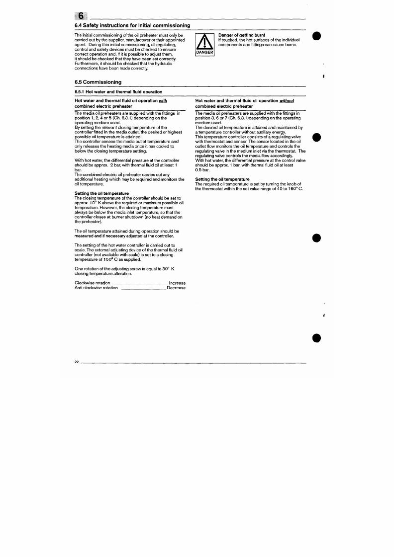
7/18/2019 M14 Thermal Fluid
http://slidepdf.com/reader/full/m14-thermal-fluid 470/486
The ini tial com miss ioning of the oi l preheater must only be
carried out by the suppl ier, manufacturer or their appointed
agent. During this ini tial com mission ing, all regula t ing,
contro l and safety dev ices must be checked to ensure
correct operation and, i f i t is possible to adjust them,
it sho uld be ch eck ed that they have been set co rrectly.
Furthermore, i t should be checked that the hydraul ic
connections have been made correctly.
Danger of getting burnt
If touc hed , the hot surfaces of the individual
com pone nts and f i t tings can cause burns.
6.5 Commissioning
6.5.1 Hot water and thermal f luid operat ion
Hot water and thermal f luid oi l operat ion with
combined electr ic preheater
The me dia oi l preh eater s are supp l ied with the f i t t ings in
posit ion 1, 2, 4 or 5 (Ch. 6.3.1) depending on the
operat ing medium used.
By sett ing the relevant closing temperature of the
control ler f i t ted in the media outlet, the des ired or high est
possible oi l temperature is attained.
The control ler senses the media outlet temperature and
only releases the heating media once i t has cooled to
below the c los ing tem perature set t ing.
With hot water, the dif ferential pressure at the control ler
sho uld be approx. 2 bar, with thermal f luid oi l at least 1
bar.
The combined electr ic oi l preheater carries out any
addi t ional heat ing wh ich may be requi red and moni tors the
oi l temperature.
Hot water and thermal f luid oi l operat ion without
combined electr ic preheater
The media oi l preheaters are suppl ied with the f i t t ings in
pos i t ion 3, 6 or 7 (Ch. 6.3.1)depending on the operat ing
medium used.
The desired oi l temperature is attained and maintained by
a temper ature c ontrol ler w ithou t auxil iary energy.
This tempe rature co ntrol ler con sists of a regulat ing valve
with therm ostat an d sensor. The sensor loc ated in the oi l
outlet f low monitors the oi l temperature and controls the
regulat ing valve in the m edium inlet via the thermo stat. The
regulat ing valve controls the media f low accordingly.
With hot water, the dif ferential pressure at the control valve
sho uld b e approx. 1 bar, with thermal f luid oi l at least
0.5 bar.
Sett ing the oi l temperature
The requ ired oi l tem peratu re is set by turning the knob of
the thermostat within the set value range of 40 to 160° C.
6.5.2 Steam operat ion
W ith steam operat ion, care should be taken
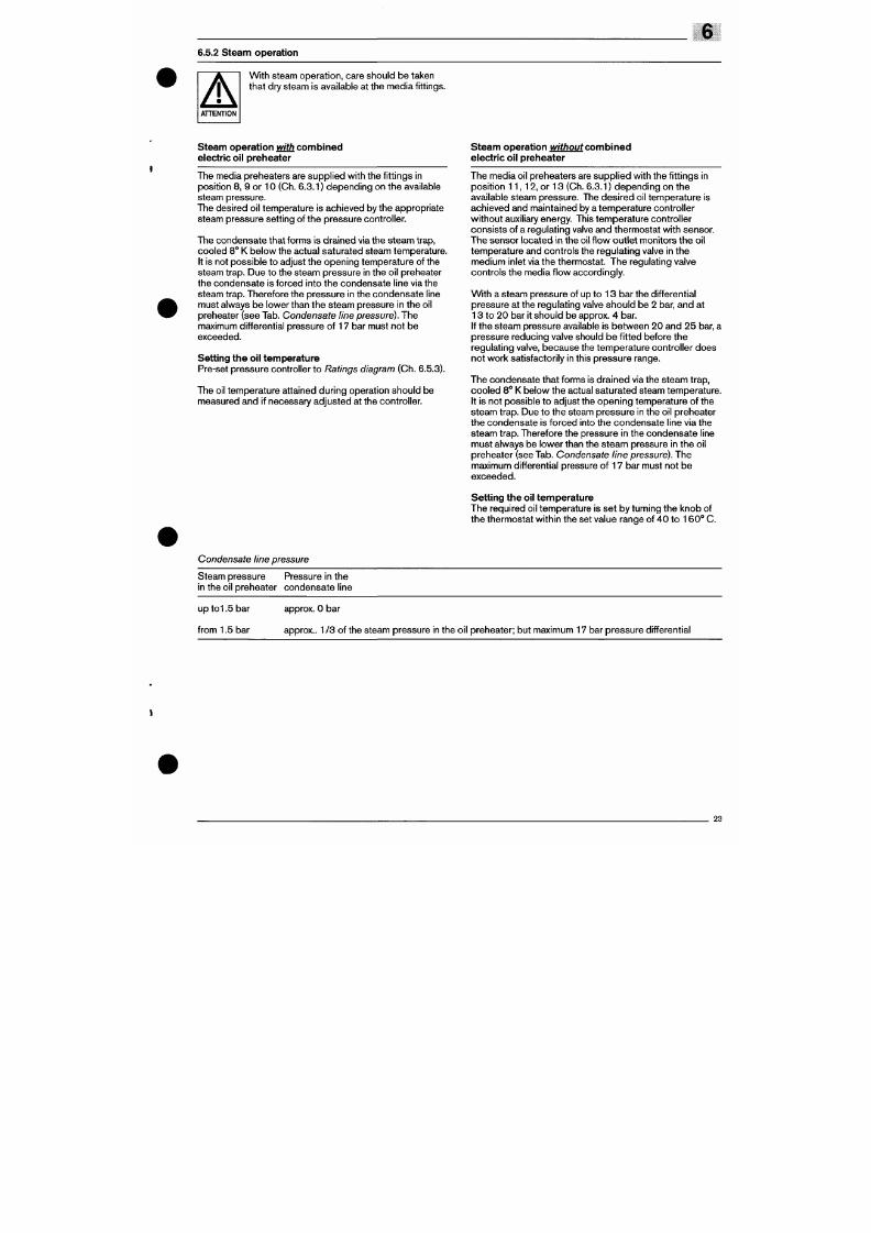
7/18/2019 M14 Thermal Fluid
http://slidepdf.com/reader/full/m14-thermal-fluid 471/486
that dry steam is available at the med ia fi tt ings.
Steam operat ion with combined
electric oil preheater
Steam operat ion iv/f / iouf combined
electric oil preheater
The media preheaters are sup pl ied w i th the f i t tings in
position 8, 9 or 10 (Ch. 6.3.1) depending on the available
steam pressure.
The desired oil temperature is achieved by the appropriate
steam pressure setting of the pressure control ler.
The cond ensate that forms is dra ined via the steam trap,
cooled 8° K be low the actual saturated steam temperature.
It is not possible to adjust the opening temperature of the
steam trap. Due to the steam pressure in the oil preheater
the conde nsate is forced in to the cond ensate l ine via the
steam trap. Therefore the pressure in the condensate l ine
must always be lower than the steam pressure in the oil
preheater (see Tab. Condensa te line pressure). The
maximum differential pressure of 17 bar must not be
exceeded.
Sett ing the oil temp erature
Pre-set pressure control ler to
Ratings diagram
(Ch. 6.5.3).
The o i l temperature atta ined dur ing operat ion should be
measured and if necessary adjusted at the control ler.
The media oi l preheaters are supplied with the fi tt ings in
posi t ion 1 1 , 12, or 13 (Ch. 6.3.1) d epend ing on the
available steam pressure. The desired oil temperature is
achieved and mainta ined by a temperature contro l ler
without auxil iary energy. This temperature control ler
consists of a regulating valve and thermostat with sensor.
The sensor located in the o il f low out le t m oni tors the o i l
temperature and controls the regulating valve in the
me dium inlet via the thermo stat. The regu lating valve
contro ls the media f low accordingly.
With a steam pressure of up to 13 bar the differential
pressure at the regulating valve should be 2 bar, and at
13 to 20 b ar it sh ou ld be approx. 4 bar.
If the steam pressure available is between 20 and 25 bar, a
pressure reducing valve should be fi tted before the
regulat ing valve, becaus e the temperature c ontro l ler do es
not work satisfactori ly in this pressure range.
The con densate that forms is dra ine d via the steam trap,
coo led 8 " K below the actual satura ted steam temperature.
It is not possible to adjust the opening temperature of the
steam trap. Due to the steam pressure in the oil preheater
6
6.5.3 Rat ings and pressure loss diagram
Ratings diagrams (maximum actiievable oil temperature with hot water and steam)
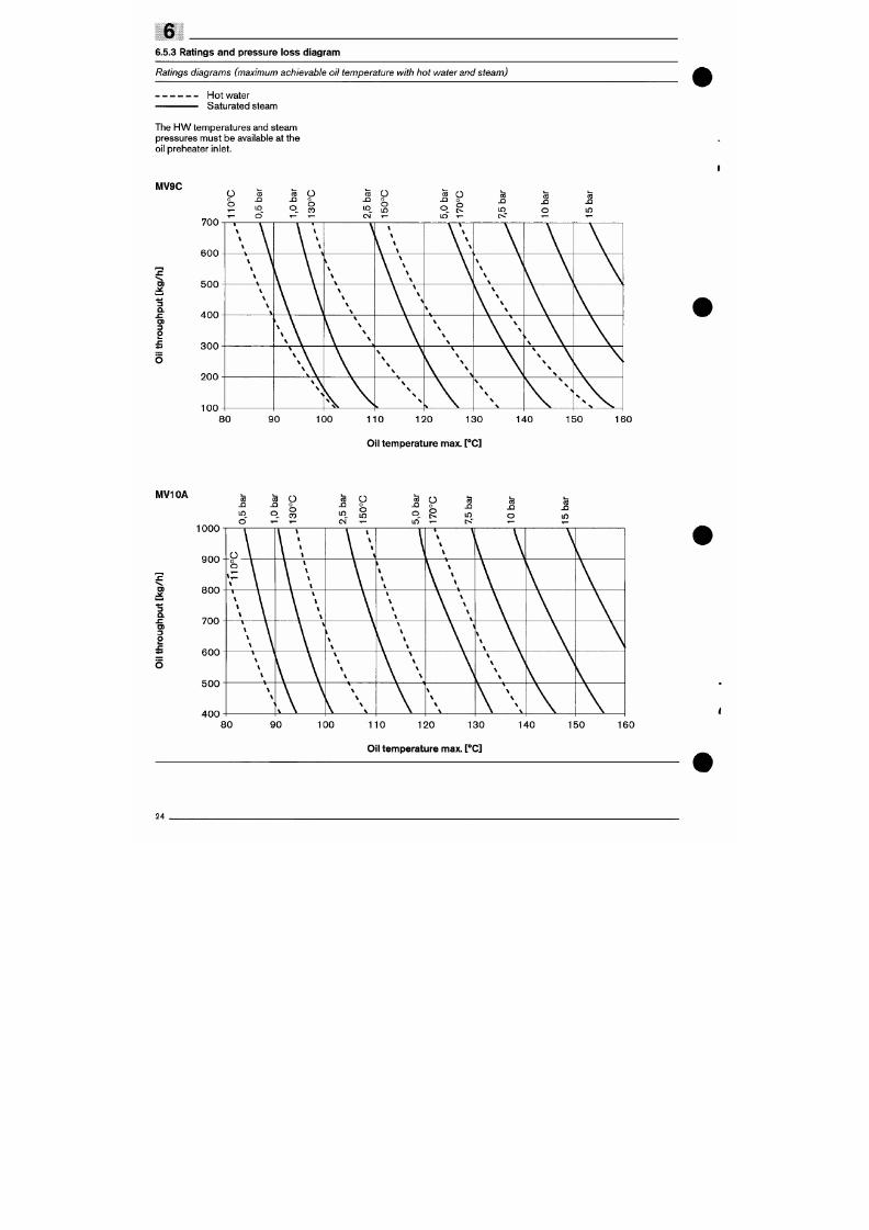
7/18/2019 M14 Thermal Fluid
http://slidepdf.com/reader/full/m14-thermal-fluid 472/486
Hot water
Saturated steam
The HW temperatures and steam
pressures must be available at the
oil preheater inlet.
IVIVSC
s
3
a
.c
O )
3
O
700
600
500
400
300
200
100
Ü S
2 in
1- O"
(B
n
o
f—
Ü
O
O
CO
T—
Co
J 3
i n
CN
()
o
o
i n
T—
Co
X
O
i n
Ü
0
O
C O
J 3
i n
IS"
C B
JQ
O
I—
C O
i n
Ä ^ k ^ \ \ _ ^ il ^ .
Fuel oil
pressure
losses MV9C / MV10A
The values have been determined using fuel oil S
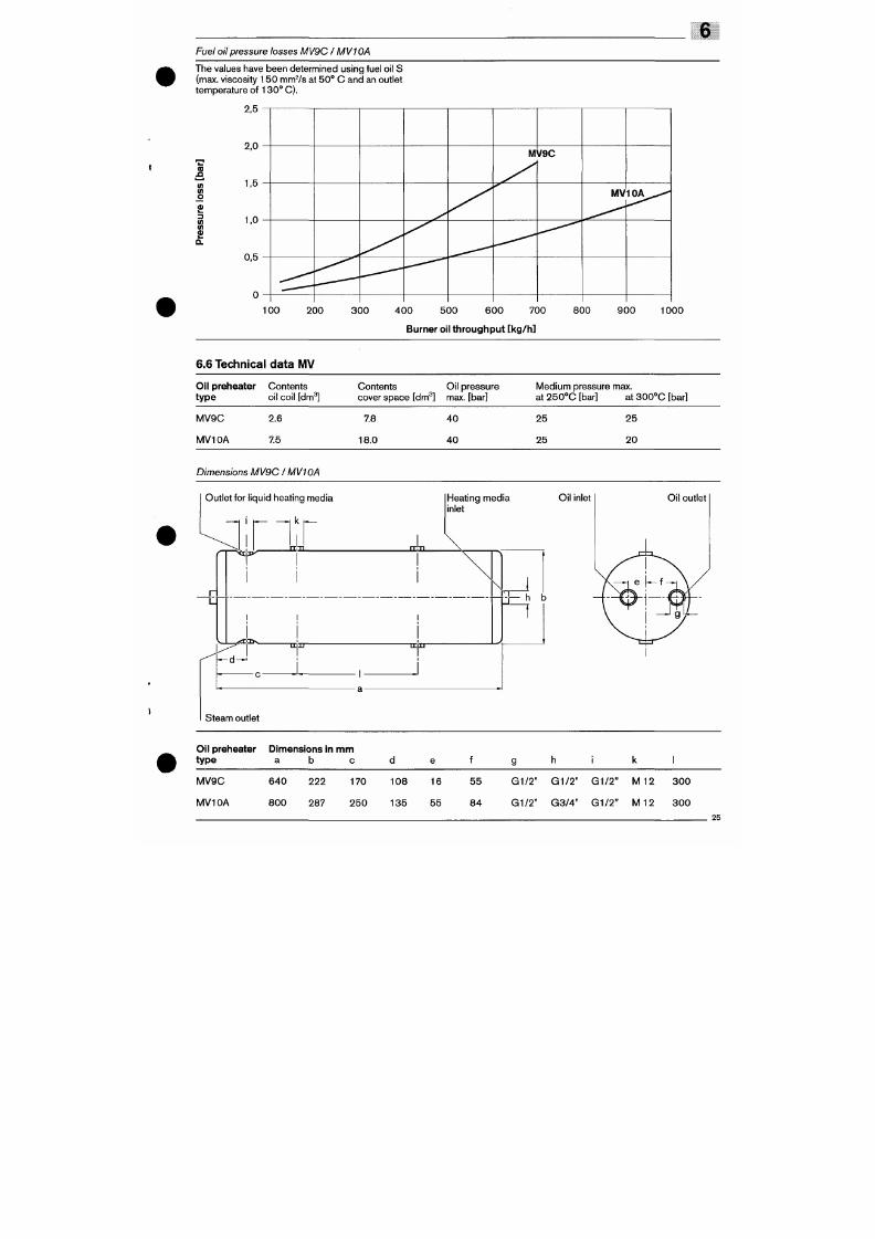
7/18/2019 M14 Thermal Fluid
http://slidepdf.com/reader/full/m14-thermal-fluid 473/486
(max. viscosity 150 mmVs at 50 ° C and an outlet
temperature of
1
30 ° C).
å
I
I
1 0 0 2 0 0 3 0 0 4 0 0 5 0 0 6 0 0 7 00
Burner oil throughput [kg/h ]
800
9 0 0
1 0 0 0
6.6 Technical data MV
Oil preheater
type
M V 9 C
Contents
oil coil [dm^]
2.6
Contents Oi l pressure
cover spa ce [dm^] max. [bar]
7.8 40
M edium pressure max.
at 2 50 °C [bar] at 30 0 °C [bar]
25 25
6.7 Saturated steam and conden sate l ines
Application example for the diagram below
Nominal diam eter of the condensa te l ine

7/18/2019 M14 Thermal Fluid
http://slidepdf.com/reader/full/m14-thermal-fluid 474/486
An oil preheater type
MV1
OA is used to preheat 900 kg/h
residual oi l from 60 ° C to 13 0° C.
Saturated steam withi 0 bar pressure is available.
At the end of the condensate l ine a pressure of 0 bar
(1 bar abs olute pressure) wil l exisit.
Saturated steam quantity required
Wit h an oil throughpu t of 9 00 kg/h a nd a At oi l of 70° K a
saturated steam quantity of 68 kg/h is required.
With 11 bar absolute pressure and a conden sate cool ing
of 8° K the condensate temperature prior to the pressure
release am ount s to 1 75° C.
Based on th is temperature and wi th 1 bar abs olute
pressure at the end of the condensate l ine, the
condens ate l ine at 68 kg/h condens ate f low must be
D N 2 5 .
Nominal diameter of saturated steam line
For a saturated steam quantity of 68 kg/h and a pressure
of 10 bar (11 bar absolute pressure) the saturated steam
line must be DN 15.
2600
2400
2200
2000
1800
1600
1400
1200
1100
1000
900
800
700
6 0 0 - 1
500
—
_::
—
-:
-
:
-
^
Saturated s team quant i ty requi red
250 "
-~I I I _ _ •
^ ^ • * " * * * * * . Ö 0 "
5 0 "
4 0 "
3 0 -
'^ 2 0 -
1'
— a u
- 70
— 60
- 50
Nom inal diameter of saturated s team l ine
D N 5 0
^ ^ — •
• 7 ^
D N 4 0 D N 3 2 D N 2 E
•^
^
D N 2 0
^ :::::::::::::
, . • • '
^ - ' '
•:.
,*
:;:;:_::::::::
DN15
DN10
Appendix
Viscosity - temperature cliart
Temperature [°F]
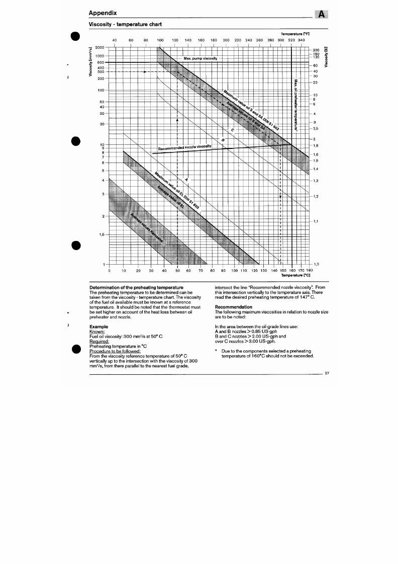
7/18/2019 M14 Thermal Fluid
http://slidepdf.com/reader/full/m14-thermal-fluid 475/486
40 60 80 100 120 140 160 180 200 220 240 260 280 300 320 340
I
1
000
2 0 0
1 0 0
__
4 0
1 0
8
4
1
^
\
V
\
\
\
\ .
—-1
1
——
\
1 1 1
Max.
pump viscosity
\ • V
X.
X
\ •«
\
\
\
\
^
1 ' v ^
1 V -
^
L S
i
\
^
\
I
\
\
Recomiiici— »- ••-
\
?,
.. v^
^
>
\
^
if
\
\
\
>
:s;
j i w -
—'
^ V
\
\
V.
s
^ ^
\
N
S
\
e viscosity
—•
s
>
\
\
1
%
%^
1
«-%>?
s. ^
ä > < c s : % .
s
\
V
. N % \ '^?
. \ ^ « S ^ S b V
1
_
^ ' ^ ^ ^ « S , .
V
«
\^
1
C?
\
s
1
^;-^^^s.%.
V '^JS^ 7
'
\
>.
N
\
\
k^
'
N
^
\
V
\
\
1
N ^ '
s
N
^
\
\
'sm
1-
^s
X
- u
f
c
-
-D
B
- 3
- a
a
- (1
3
•0
(I
B
. C
a
N
\
•
»
\
\
1
S
\
—
—
200 a
—
150
3
•2,5
2
1,8
1,6
1,5
1,4
1,3
i n
>
120
K
8
60
40
30
20
10
8
6
Weishaupt products
and service
Max Weishaupt GmbH
D - 884 75 Schwendi
Tel.: (07353) 83 0, Fax.: (07353) 8 3358
www.weishaupt.de
Print No. 83001802, July 2005
Printed in Germany. All rights reserved.
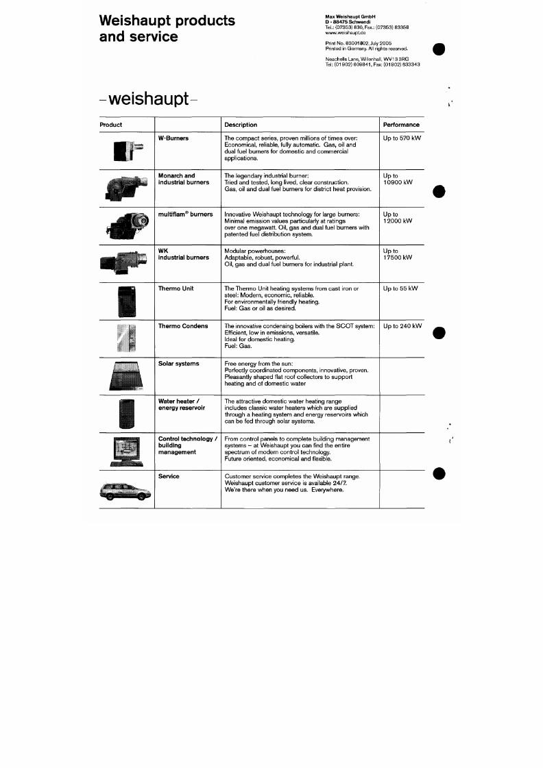
7/18/2019 M14 Thermal Fluid
http://slidepdf.com/reader/full/m14-thermal-fluid 476/486
Neachells Lane, Willenhall, W V13 3RG
Tel: (01902)
609841,
Fax: (01902) 6333 43
-weishaupt
Product
1.
år
< é l P
W-Bu me r s
Monarch and
industrial burners
multif lam® burners
W K
industrial burners
Description
The com pa ct ser ies, proven m i ll ions of t imes over:
Eco nom ical, rel iable, ful ly autom atic. Ga s, oi l and
dual fuel burners for domest ic and commercial
appl icat ions.
The legendary industr ia l burne r:
Tr ied and te sted , long
l ived,
c lear construct ion.
Gas, oi l and dual fuel burners for district heat provision.
Innovat ive Weishaupt technology for large burners:
Minimal emission values particularly at ratings
over one megawatt . Oi l , gas and dual fuel burners wi th
patented fuel distr ibut ion system.
Modular powerhouses :
Adaptable, robust , powerful .
Per formance
Up to 570 kW
Up to
1 0 9 0 0 k W
Up to
1 2000 kW
Up to
1 7 5 0 0 k W
1/81 GB
Instructions for
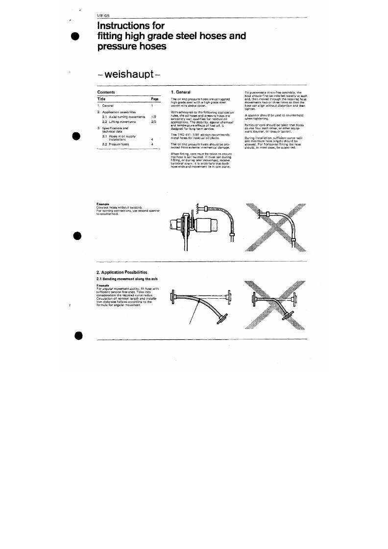
7/18/2019 M14 Thermal Fluid
http://slidepdf.com/reader/full/m14-thermal-fluid 477/486
fitting Fiigh grade steel hoses and
pressure hoses
- w e i s h a u p t -
Contents
Tit le
1. General
2. Applicat ion possibi l i tes
2.1 Axia l turning movements
2.2 Li f t ing movements
3. Specification s and
technical data
3.1 Hoses in oil supp ly
installations
3.2 Pressure hoses
Page
1
1/2
2/3
4
4
1. General
The oil and pressure hoses are corrugated
high grade steel w it h a high grade steel
woven wire sleeve cover.
With adherence to the fol lowing applicat ion
rules,
the oil hoses and pressure hoses are
extremely well qual i f ied for residual oi l
app/ icat ions. The sta bi l i ty , against chemical
and temperature ef fects of fuel oi l , is
designed for long term service.
T he T R D 4 1 1 , 7/81 edit ion recommends
metal hoses for residual oil plants.
The oil and pressure hoses should be pro
tected fro m e xternal mechanical damage.
When f i t t in g, care must be taken to ensure
the hose is not twisted . I t must not du ring
f i f t ing . or during later movement, receive
torsional strain, i t is important that both
hose ends and movement lie in one plane.
To guarantee a strain-free assembly, the
hose should first be installed loosely at each
end,
then moved through the required hose
movements two or three times so that the
hose can al ign without distort ion and then
t igh ten .
A spanner should be used to counterhold
when t ightening. '
Particular care should be taken that hoses
do not foul each other, or other equip
ment (burn er, oi l l ines or bo i ler).
During instal lat ion, suf f ic ient curve radi i
and min imu m hose lengths should be
a l lowed. For horizontal f i t t ing the hose
shou ld , in most cases, be supported.
Example
Angular m ovement and hose curves must l ie
in one plane. Damaging torsional strain is
thus avoided.
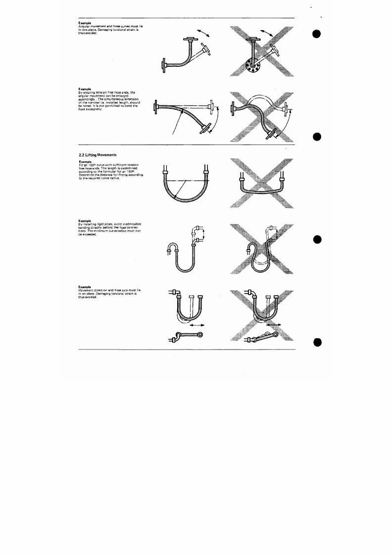
7/18/2019 M14 Thermal Fluid
http://slidepdf.com/reader/full/m14-thermal-fluid 478/486
t
I
Example
By ensuring tension free hose ends, the
angular movement can be enlarged
accordingly . The simultaneous extension
of the nom inal i .e. installed leng th, should
be noted. I t is not permitted to bend the
hose excessively.
2.2 L i f t ing Movem ents
Example
Fit an 180° curve with suff icient tension
free hose ends. The length is determined
according to the formular for an 180°.
Determine the distance for f i t t ing according
to the required curve radius.
Example
By instal l ing r igid pipes, there is no varying
curve strain and no very sharp bends dire ct ly
behind the hose conne ct ions.
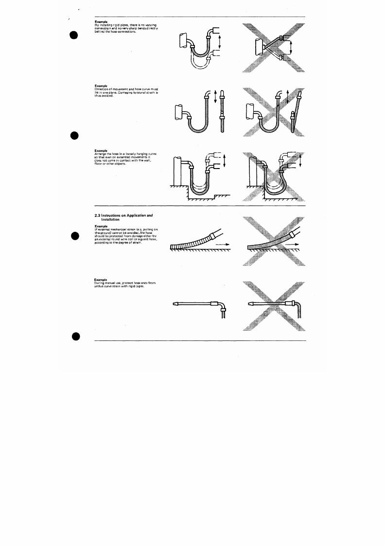
7/18/2019 M14 Thermal Fluid
http://slidepdf.com/reader/full/m14-thermal-fluid 479/486
Example
Direct ion of movement and hose curve must
lie in one plane. Damaging torsional strain is
thu s avoided.
Example
Arrange the hose in a loosely hanging curve
so that even on extended movements it
does not come in contact with the wa l l ,
f loor or other objects.
"<:
f l ^''
^Jk
3. Specifications and Technical Data
3.1 Oi l hoses in oi l supply instal lat ions
(f low and return)
3.2 Pressure hoses (between pump and
nozzle)
must be allowed for. This length must stay
straigh t, i .e. the curve radius may n ot start
unt i l af ter this straight sect ion.
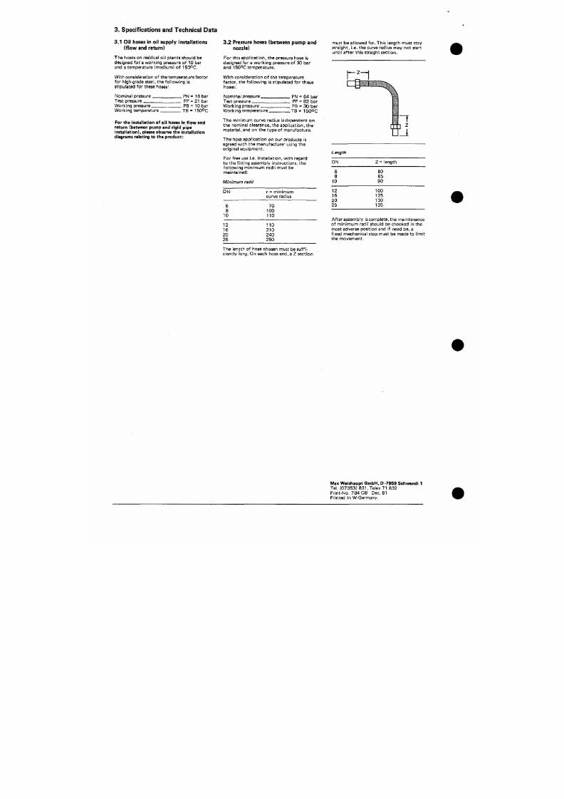
7/18/2019 M14 Thermal Fluid
http://slidepdf.com/reader/full/m14-thermal-fluid 480/486
The hoses on residual oil plants should be
designed for a work ing pressure of 10 bar
and a temperature (me dium) o f 1 50°C.
With considerat ion of the temperature factor
for high-grade steel, the fol low ing is
stipulated for these hoses:
Nominal pressure.
Test pressure
Working pressure
Work ing temperature.
_P N = 16 bar
. PP = 21 bar
. PB = lo ba r
. TB = 150°C
For the installation of oil hoses in flow and
return (between pump and rigid pipe
Installa tion), please observe the installation
diagrams relating to the produ ct:
For this a pplic at ion , the pressure hose is
designed for a workin g pressure of 30 bar
and 150°C temperature.
With considerat ion of the temperature
factor, the fol lowing is st ipulated for these
hoses:
Nominal pressure.
Test pressure.
Work ing pressure
Work ing temperature.
. PN = 64 bar
. PP = 82 bar
. PB = 30 bar
. T B = 1 5 0 O C
The minimum curve radius is dependent on
the nominal clearance, the applicat ion, the
mater ial ,
and on the type of manufacture.
The hose applicat ion on our products is
agreed with the manufacturer using the
or iginal equipment .
For free use i.e. installat io n, with regard
to the f i t t ing assembly instruct ions, the
fol lowing m inimu m radi i must be
maintained:
Minimum radii
D N
r = minimum
curve radius
6
8
10
70
100
110
~ 1
Z
m
ength
DN
6
8
10
12
16
2 0
25
Z = length
80
85
90
100
125
130
135
12
16
2 0
25
110
210
240
250
After assembly
is
complete, the maintenance
of minimum radii should be checked in the
most adverse po sition and if need be, a
f ixed mechanical stop must be made to l imit
the movement .
The length of hose chosen must be
suf f i
c ient ly
long.
On each hose end,a Z sect ion
TYPE FT 3L
.mm
-LENGTH IN MM
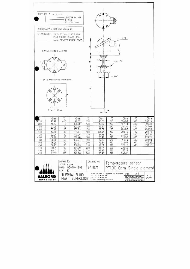
7/18/2019 M14 Thermal Fluid
http://slidepdf.com/reader/full/m14-thermal-fluid 481/486
-3 WIRE
•PT 100 Ohm
ACCURACY
: IEC 751
class
B
STANDARD : TYPE PT 3L = 215 mm
ENCLOSURE CLASS IP54
MAX. TEMPERATURE 550°c
CONNECTION DIAGRAM
1 or 2 Measuring elements
ISO- VIEW
A - A
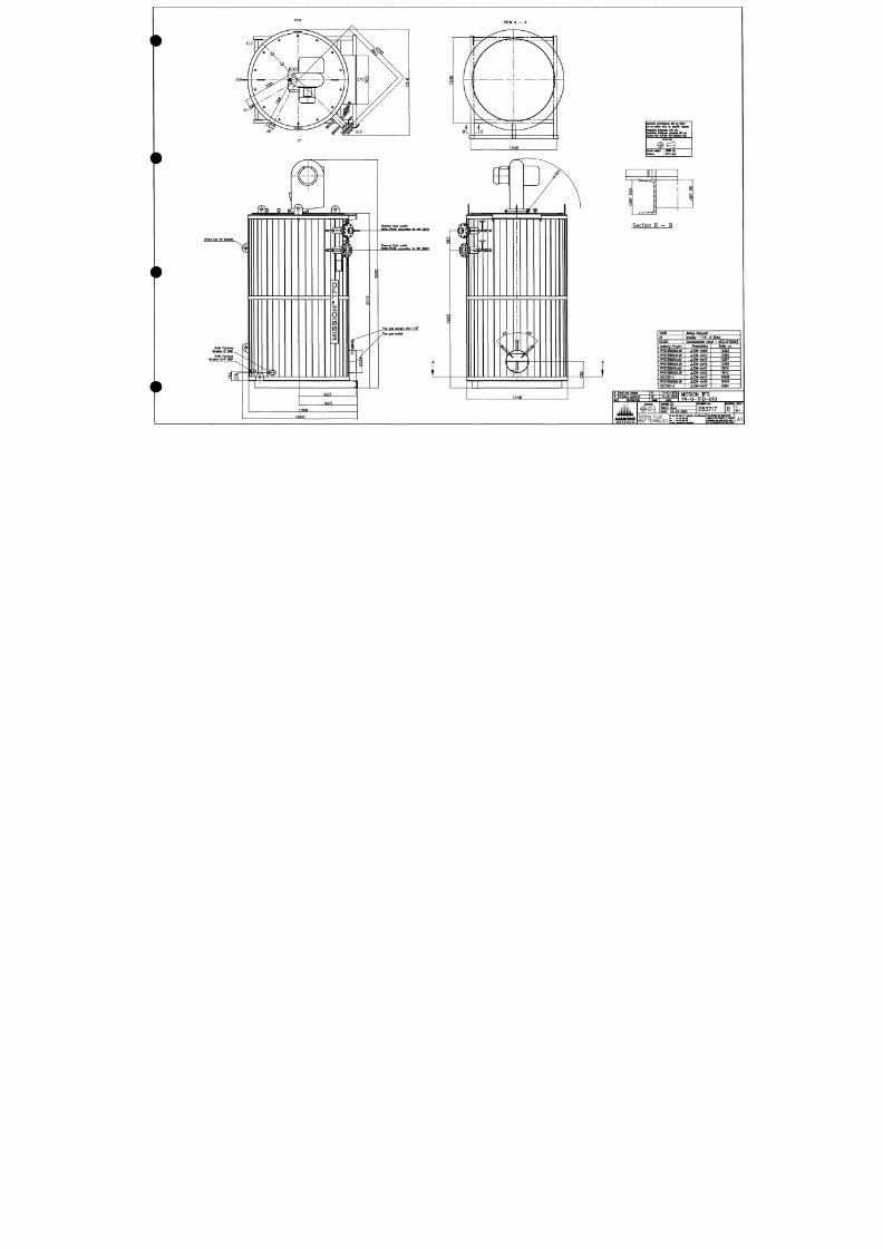
7/18/2019 M14 Thermal Fluid
http://slidepdf.com/reader/full/m14-thermal-fluid 482/486
0'
Li fti ng Ey for h»a< l «r
ThWTTKl fluid OUtlSt
DN80/ t 'N25 occardHa to D I N 2634
Iharniol fluM OMtlat
DNaO/ ('N25 aeconl l na to D I N 2634
Fl u« ga« »am pta pi p« 1/ 2*
comrafponv M M offsnl
laon
ony^
on ipvcnlc
knulatcn 1Nckn«ii 120 nwn
kwiiiUw IMclaiw« bockiM« 80
jacM HSA
B/0O-11B
IW50a2
^
Ei ti ptyi n l ^ : 3000 Kg
: STJUI ra
O
o
a
z
3
>
o
CO
a.
z
3
Section B — B
YAIW : Minq Shk)yarti
At : Nanßng - RR. of
China
CLASS : Germanischer Uoyd + UCE.AU1(SBG)
Aabcrg ProiKt
PP573a659A.00
PP5738660A.00
PP5738661A.W
PP5738662A.00
PP573BB41A.00
PP5738B42KO0
052352-1
PP5739698A.00
052352-2
Newbuldhg
JLZ04-04O9
JLZ0*-0410
JLZ0*-0413
ÅZ04-0414
1204-0411
1204-0412
1204-0415
1204-0416
1204-0417
Baler no.
15393
15395
15397
15399
15610
15612
16939
16605
16941
Hull nra added
Dnwiinq updated
DESCaPTKW
«Uiliiii
AAIBORG
I N D U < T « I I *
PJ
CE
1 3 - 0 2 - 2 0 0 6
1 9 - 0 4 - 2 0 0 5
PATt
MISSION TFO
V4-0-TF0-010
ORAW tCE
SCME None
D A T E 1 6 - 0 3 - 2 0 0 5
D R M M G N E
D53717
THERMAL FLUID
HEAT TECHNOLOGY
w : 4 a « m a
REWn«
B
M H i c n o a n r v M M H
SHEET
1
ori
AI
CQ2 Co n n . R 5 / 4 "
No z z le TF1 4 XW 3 / 8 " ( 2 x)
S e c t i o n
B
—B
Im m e rs io n tu b e
Marking
o f
o r i f ic e p lo a t
Gasl<et DN25
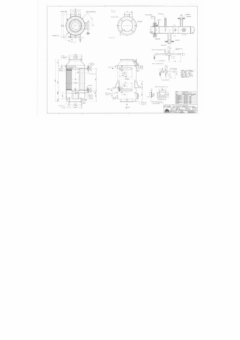
7/18/2019 M14 Thermal Fluid
http://slidepdf.com/reader/full/m14-thermal-fluid 483/486
Ex t in g u is h n o z z le
o
LO
LO
•<
022 (36x)
f le u gas f la n g e s
a c e D IN8 6 0 4 4
O
in
in
o
o
oo
to
f
01366
P.C. 01310
CD. 01226
o
CD
Cle o n in g n o z z le .
Dra w
t u r n e d
45°
Se e to p v ie w.
O
o
IT)
iXXM>i>3.
<>
>, r-p ,r-\
o 0
» o
1226
P.C. 01310
01366
DN2 5 PN4 0
DN8 0 PN4 0
m m e rs io n tu b e .
O
o
CD
CM
DN80 PN40
O
o
CM
O
O
CM
}
DN40 PN40
Cle a n in g n o z z le .
Dra w
t u r n e d
15°
Se e to p v ie w.
O
o
CD
100
o
k
View A-A
Th e rm a l F lu id
In le t
Th e rm a l F lu id
Ou t le t
CO 2
C o n n e c t i o n R 3 / 4 "
Se e v ie w A—A
LU
4
i>- 4~ ^
400
I
o
in
CM
Detai l cleaningnozzle
40
17
Sta in le s s s te e l p ip e
0 2 1 . 3 X 2 . 6 5
NUMBER OF ECONOMSERS : 1
HEAT CAPACTY : 1000 kW
INLET TEMP : 150 °C
OUTLET TEMP : 200 "0
WEGHT EMPTY : 5800 kg
LIQUID VOLUME : 1553 Itr
FLANGES AGO DN
Nozzle TF14XW 3 /8"
D e t a i l I n s p e c t i o n h o l e
10
550
in
o
CM
40 1
CO
o
CM
CO
o
CM
of
470
U-
300=
o
to
o
lO
20 170
170 170
Te s t c o n n e c t io n
Im m e rs io n tu b e
See view A-A
( l O x )
Hex,
h e a d b o l t M1 0 x 4 0
+
nut +
wa s h e r (D IN9 3 1 ,9 3 4 ,1 2 5 )
+ g a s k e t (g la s s c o rd ø8 )
YARD
:
Jinling Shipyard
At
:
Nanjing
- P.R. of
China
CLASS
:
Germanischer Lloyd
+
MCE,AUT(SBG)
Aalborg Project
PP5758661A.00
PP5738662A.00
PP5738841A.00
PP5758842A.00
052552-1
PP5759698A.00
052352-2
Newbuilding
JLZ04-0413
JLZ04-0414
JLZ04-0411
JLZ04-0412
JLZ04-0415
JLZ04-0416
JLZ04-0417
Boiler no.
15398
15400
15611
15613
16940
16606
16942
Flue gas
I n let
REV
Hull
nrs.
a d d e d
DESCRIPTION
iiUUib
AALBORG
I N D U S T R I E S
PJ
NAME
PROJECTON
1 4 - 0 2 - 2 0 0 6
DATE
Economiser
E X V 6 6 0 - 4 3 - 5 7 , 0 - 6 0 0
DRAWN CE
SCALE none
DATE
1 1 - 1 1 - 2 0 0 5
DRAWING No:
D54051
T H E R M A L F L U I D
PO
Box145
3200
AC
S l n ^
The
Nethernds
Td
: +31
181
650500
ML H I I L V ^ n i N U L U U I E _ap rmw10bog ndu3Wesn
REVSON
A
IHIS DRAMNG
AND
DESGN SHOWN
HERQN
ISTHE
PROPERTY
OF
AABORG
INDUSTRES
AND
MUST
NOTBE
USED
BY
OR
RERODUCED
FOR
THRD PARTY
SHEET
1
0F 1
AI
1739
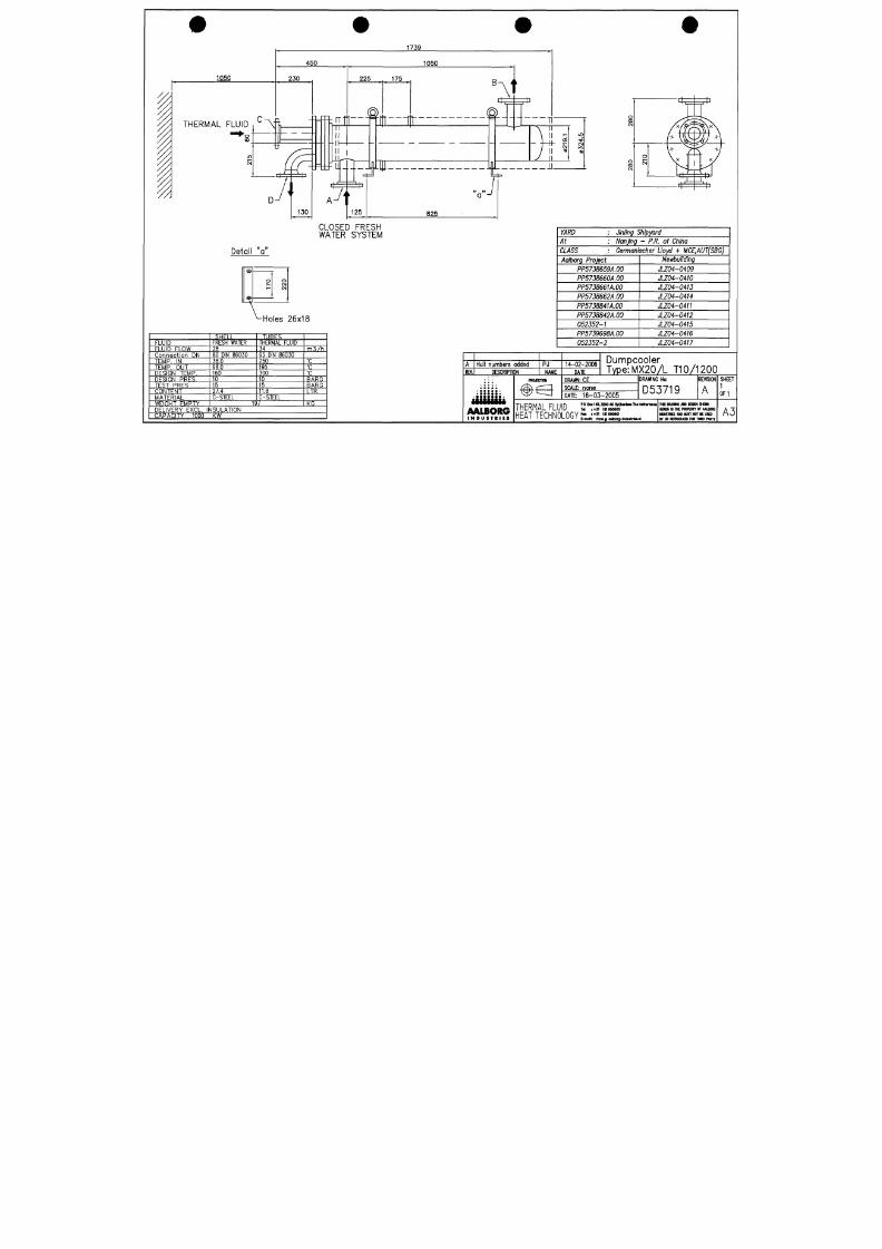
7/18/2019 M14 Thermal Fluid
http://slidepdf.com/reader/full/m14-thermal-fluid 484/486
CLOSED FRESH
WATER SYSTEM
Detail "a''
æ
s
o
1^
o
CM
CM
•Holes 26x18
FLUID
FLUID FLOW
C o n n e c t i o n D N
T E M P .
IN
T E M P . O U T
DESIGN TEMP.
D E S I G N P R E S .
T E S T P R E S
C O N T E N T
M A T E R I A L
W E I G H T E M P T Y
SHE
FRESI-
LL
WATER
28
80 DIN 86030
38.0
68.0
160
10
15
27.4
C-STEEL
T U B E S
THERMAL FLUID
34
65 DIN 86030
250
195
300
10
15
11.8
C-STEEL
197
m 3 / h
•c
•c
•c
BARG
BARG
LTR.
KG
D E L I V E R Y E X C L . I N S U L A T I O N
C A P A C I T Y 1 0 0 0 K W
YA RD : Ming Shipyard
At : Nanjing - P.R. of China
CLASS :
Germanischer
Lloyd +
MCE,AUT(SBG)
Aalborg Project
PP5738659A.00
PP5758660A.00
PP5738661A.00
PP5758662A.00
PP5738841A.00
PP5738842A.00
052352-1
PP5739698A.00
052352-2
Newbuilding
JLZ04-0409
JLZ04-0410
JLZ04-0413
JLZ04-0414
JLZ04-0411
JLZ04-0412
JLZ04-0415
JLZ04-0416
JLZ04-0417
R E V.
Hull numbers added
DESCRIPTION
iililiiii
AALBORG
I N D U S T R I E S
PJ
N A M E
PROJECIW
#€3
14-02-2006
D A T E
Dumpcooler
Type:MX20/L T10/1200
DRAWN: CE
SCALE: none
DATE: 16-03-2005
DRAWING No:
D53719
R E V I S I O N
T H E R M A L F LU ID
H E A T T E C H N O L O G Y
PO Box 14% 3200 AC S p lJwilM 1hl N t t lw lani l l
Til :+3 i imesosoo
F« :+31 1B1690501
E-nwl: rtmwø qdbofy-fcidurtriit jil
A
1HS DRA«MG AW DESKN SHOW
HEREM IS IHE PROFERTY OF AAUORG
MUSUCS AM) UUST NOT
BE
USED
BY OR REPRODUCED FOR IHRD PARTY
S H E E T
1
0 F 1
A3
YARD : Jinling Shipyard
A t :
Nanjing
- P.R. of
China
CLASS : Germanischer Lloyd + MCE,AUT(SBG)
Aalborg Project
PP5738659A.00
Newbuilding
JLZ04-0409
#
CIRCULATING
Type:
NTT
PUMP
50-200
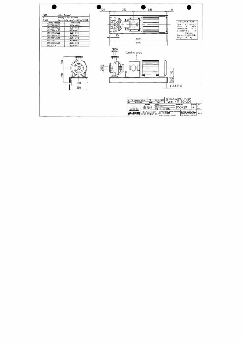
7/18/2019 M14 Thermal Fluid
http://slidepdf.com/reader/full/m14-thermal-fluid 485/486
PP5738660A.00
PP5758661A.00
PP5738662A.00
PP5738841A.00
PP5738842A.00
052352-1
PP5739698A.00
052352-2
JLZ04-0410
JLZ04-0413
JLZ04-0414
JLZ04-0411
JLZ04-0412
JLZ04-0415
JLZ04-0416
JLZ04-0417
CAP.:
Del.head
34
:80
E-motor:15.0
Current :
Weight:
myh
m.l.c.
kW
Siemens
3x440V-60Hz
231.5
kg
R E V.
Hull numbers added
D E S C R I P T I O N
PJ
N A M E
14-02-2006
D A T E
CIRCULATING PUMP
Type :
NTT 5 0 -2 0 0
AALBORG
I N D U S T R I E S
P R O J E C I K M
DRAWN: CE
SCALE: none
DATE: 1 6 - 0 3 - 2 0 0 5
DRAWING
No:
D53720
THERMAL FLUID ^ ' ^ l ^ ^ Ä ' " - " " ' * - ^
HEAT TECHNOLOGY l ^ r i J ^ r ; - . ^ .
R E V I S I O N
A
1HS nUMNG M O DESKN SHOWN
HBS M E 1NE PROPERTY OF AAUORG
•DUSIRE S «NO MUST NOT BE USED
BY OR REPROniCED FDR 1HRD PARTY
SHEET
1
0F1
A3
POSITION
1 Level switch
2 Level indicator
MAN/INSPECTIONHOLE ORIENTATION
DM
E -
DRAINLINE EXPANSION LINE
IN ACCORDANCE WITH
DIN
4 7 5 4
KW
2400
DN
E
DN
65
TUBE
76.1
X 3.2
DN
A
DN
50
TUBE
6 0 .3
X 2.6
2/3 xF
'^^Oi
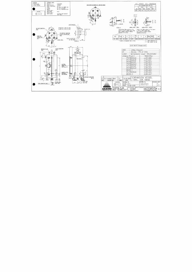
7/18/2019 M14 Thermal Fluid
http://slidepdf.com/reader/full/m14-thermal-fluid 486/486
CM
DETAIL A
welding detai l : SHELL welding detai l : NOZZLE
Thermal fluid fi l l ing contents of the
system in l i tres at 200'C supply temp,
with a safety o f 30% on thermal
expansion of the fluid
Thermal fluid fi l l ing contents of the system
in l i tres at 300'C supply temp,
with a safety of 30% on thermal
expansion of the fluid
TYPE
SVE 5950
Content
1430
A
505
D
900
F
6
G
600
**
H
2860
K
100*100*10
N
1700
* *
Weight
700
* * *
Weight
1065
4000
NW
DN400
* Contents of expansion tank in l i tres
* *
EMPTY WEIGHT
I N K g
* * * WET
WEIGHT
I N K g
DO
NO T
INSULATE EXPANSION VESSEL
YA RD Jinling Shipyard
At Nanjing -
P,R,
of China
CLAS S '• Germanischer Lloyd +
MCE.AUTCSBG)
Aalborg Project
PP5738659A.00
PP5738660Am
PP5738661Am
PP5738662Am
PP5738841A.00
PP5738842A.00
052352-1
PP5739G98Am
052352-2
tiewbuilding
JLZ04-0409
JLZ04-0410
JLZ04-0413
JLZ04-0414
JLZ04-0411
JLZ04-0412
JLZ04-0415
JLZ04-0416
JLZ04-0417
^ DN25 PNI6
REV.
Hul l numbers added
DESCRIPTION
• • • • • • •
iiiiiiiit
AALBORG
I N D U S T R I E S
PJ
NAME
PROJECTON
^ ^
13-02-2006
DATE
EXPANSION VESSEL
TYPE: SVE 5950
D R A W N : C E
S C A L E :
n o n e
DATE:
16-03-2005
DRAWING
No:
D 5 3 7 2 1
T H E R M A L F L U ID
PC Box 145, 3200 AC Spicenisse, The Netheriands
Tel : +31 181 650 500
H E A T T E C H N O L O G Y ' " =' " '' ''' °°
l l l _ /- \ l I U V > ^ I I M V l _ W I E_m(|| rtmw9aalborg-industries.nl
REVISION
THIS BRAVING AND DESIGN SHDVN
HEREIN IS THE PRDPERTY DF AALBDRp
INDUSTRIES AND MUST NDT BE USED
BY GR REPRDDUCED FDR THIRD PARTI
SHEET
1
0F1
A3