m2, ms , m10 and m20 variac® autotransformers m5 , m10, and m20 variac...
TRANSCRIPT

OPERATING INSTRUCTIONS
M2, MS, M10 and M20 VARIAC® Autotransformers
with DURATRAK Coating Process (U.S. Patent No. 2,949,592)
GENERAL INSTRUCTIONS
1.1 LINE VOLTAGE AND FREQUENCY. The M series Variac® autotransformers are designed for use at frequencies between 350 and 1200 cycles per second (cps) on 120-volt lines. Operation at frequencies below 350 cps is permissible
if the line input voltage does not exceed 120 X 3;
0, where f
is the lower frequency. Under no circumstances should the input voltage exceed 125 volts for the overvolfage connection (147 volts across the complete winding), since, above this value, the voltage across the brush will be excessive.
Variac autotransformers cannot be operated on direct current. Any attempt to do so will result in a burned-out unit.
1.2 FUSES AND LINE CAPACITY. Protect your unit by placing a fusing device of proper rating between terminal 3 and the load. The input line capacity must be adequate for the Variac au o ransformer, tfS load,a<raJf!Onil oa s a may be required, and a margin for slight overload. Because these transformers are iron-cored devices using high-performance core material, normal inrush surges up to 10 times the rated current of the unit may be encountered when the unit is first connected to the line. Fuses must be selected with this in mind.
Slow-blow (thermal delay) fuses or magnetic or thermal time-current integrating breakers are preferable to the quickblow fuse, for the input line and the load circuits. Such devices as Klix6n and Heinemann circuit breakers are particularly useful where the load is subject to high inrush.
The short-term overload curve, Figure 1, shows what your
1000
900
800 (!)
~ 700 1-<l a: 600
..J
~ 500 a: 0400 z 0300 st'
100
0 .01
Figure 1. Overload limits for line-voltage connection.
l\'ovERLOAD LIMIT
\
1\
\ 114HDU -150~ I I
"' ·~r::3: i I I I
"' • -1 a
"" 11_ 4 HOURS-100'1.
i'- l.l. l
0.1 I 2 5 10 100 1,000 10,000
TIME IN MINUTES
autotransformer will stand under initial surge conditions, as in motor starting, incandescent lamp lighting, etc. At no time should the unit be called upon to furn ish a current in excess of ten times its rated current.
1.3 LOADS. Variac autotransformers are adaptable to any load that is subject to control by voltage variation. As a rule, induction motors cannot thus be smoothly controlled. However, de motors (with rectifiers), universal motors (with or without rectifiers), capacitor motors with fan loads, heaters, lights, and many other devices are suitable for such control.
The overvoltage connection should be avoided where the load may be damaged by the higher-than-line voltage available. When the overvoltage connection is omitted, with a fixed, known load, maximum current may be drawn at line voltage. Since losses which var with brush setting) are at a minimum near line an zero vo tages, .higher current can bCCfrawn a-t- these settings without exceeding normal temperature ratings. This higher (maximum) current is of such value that, as the brush setting is reduced below line voltage, with a constantimpedance load, the current fall-off with decreasing output voltage keeps the current within safe limits. To find the impedance in ohms of the minimum ohmic load, divide line volts by maximum amperes. The power rating of this load in watts is the product of line volts and maximum amperes.
For continuous operation, the rated current of the transformer should not be exceeded. Derate the unit in accordance with Figure 2 for ambient temperatures above 50 C.
100
90
80
C)
!!: ro ,_ <t cr60 _, <t ::1! 50 cr 0 z 40 -1
30
2 0
10
0 30 86
Figure 2. Temperature derating curve.
40 104
""
50 122
" !'-._
60 140
"' ""'
70 158
AMBIENT TEMPERATURE
[\_
t\
80 176
\ 1\ \
I 90 0<9 c
194 009 F
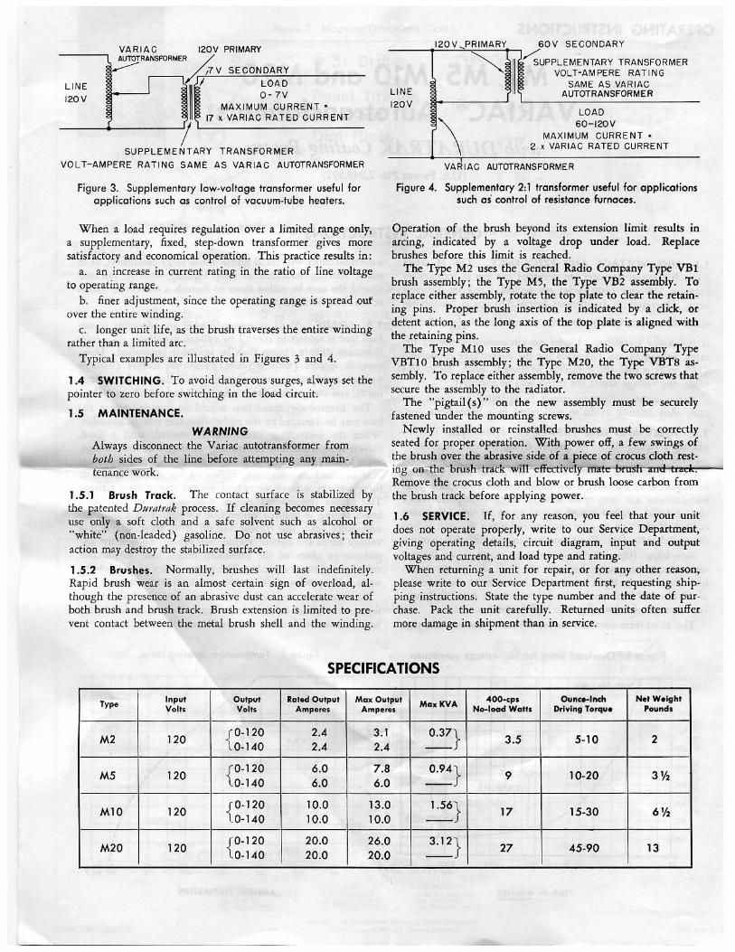
VARIAC 120V PRIMARY 120V ,PRIMARY 60V SECONDARY
AUTOTRANSFORMER ~
/rJLV SECONDARY
LINE 120V
II/ MAXIMU~~J1RRENT • LINE
120V
~-~1 II~UPPLEMENTARY TRANSFORMER VOLT-AMPERE RATING
SAME AS VARIAC AUTOTRANSFORMER
I 17 x VARIAC RATED CURRENT
SUPPLEMENTARY TRANSFORMER
VOLT- AMPERE RATING SAME AS VARIAC AUTOTRANSFORMER
Figure 3. Supplementary low-voltage transformer useful for applications such as control of vacuum-tube heaters.
When a load requires regulation over a limited range only, a supplementary, fixed, step-down transformer gives more satisfadory and economical operation. This practice results in:
a. an increase in current rating in the ratio of line voltage to operating range.
b. finer adjustment, since the operating range is spread ouf over the entire winding.
c. longer unit life, as the brush traverses the entire winding rather than a limited arc.
Typical examples are illustrated in Figures 3 and 4.
1.4 SWITCHING. To avoid dangerous surges, always set the pointer to zero before switching in the load circuit.
1.5 MAINTENANCE.
WARNING Always disconnect the Variac autotransformer from both sides of the line before attempting any maintenance WOrk.
1.5.1 Brush Track. The contact surface is stabilized by the patented D11rat1·ak process. If cleaning becomes necessary use only a soft doth and a safe solvent such as alcohol or "white" (non-leaded) gasoline. Do not use abrasives; their action may destroy the stabilized surface.
1.5.2 Brushes. Normally, brushes will last indefinitely. Rapid brush wear is an almost certain sign of overload, although the presence of an abrasive dust can accelerate wear of both brush and brush track. Brush extension is limited to prevent contact between the metal brush shell and the winding.
r\ LOAD
60-120V MAXIMUM CURRENT •
2 x VARIAC RATED CURRENT
VARIAC AUTOTRANSFORMER
Figure 4. Supplementary 2:1 transformer useful for applications such as control of resistance furnaces.
Operation of the brush beyond its extension limit results in arcing, indicated by a voltage drop under load. Replace brushes before this limit is reached.
The Type M2 uses the General Radio Company Type VBl brush assembly; the Type M5, the Type VB2 assembly. To replace either assembly, rotate the top plate to clear the retaining pins. Proper brush insertion is indicated by a click, or detent action, as the long axis of the fop plate is aligned with the retaining pins.
The Type MlO uses the General Radio Company Type VBTl 0 brush assembly; the Type M20, the Type VBTS assembly. To replace either assembly, remove the two screws that secure the assembly to the radiator.
The "pigtail ( s)" on the new assembly must be securely fastened under the mounting screws.
Newly installed or reinstalled brushes must be correctly seated for proper operation. With power off, a few swings of the brush over the abrasive side of a piece of crocus doth resting on~the brush track will effectively mate-brush and track. Remove the crocus cloth and blow or brush loose carbon from the brush track before applying power.
1.6 SERVICE. If, for any reason, you feel that your unit does not operate properly, write to our Service Department, giving operating details, circuit diagram, input and output voltages and current, and load type and rating.
When returning a unit for repair, or for any other reason, please write to our Service Department first, requesting shipping instructions. State the type number and the date of purchase. Pack the unit carefully. Returned units often suffer more damage in shipment than in service.
SPECIFICATIONS ·
Type Input Output Rated Output Max Output MaxKVA 400-cps Ounce-Inch Net Weight Volts Volts Amperes Amperea No-load Watts Driving Torque Pounds
M2 120 {0-120 2.4 3.1 0.37} 3.5 5-10 2 0-140 2.4 2.4
M5 120 {0-120 6.0 7.8 0.94} 9 10-20 3% 0-140 6.0 6.0
M10 120 {0-120 10.0 13.0 1.56} 17 15-30 6% 0-140 10:0 10.0
M20 120 {0-120 20.0 26.0 3.12} 27 45-90 13 0-140 20.0 20.0
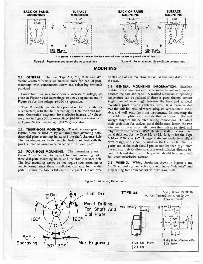
lACK-OF-PANEL MOUNTING
I L __ _____ __ .J LINEa 12t nlll LOADa D-140 'NIII
SURFACE MOUNTING
lACK-OF-PANEL MOUNTING
LINEa 12t wolll LOADa 0-l:lt nils
SURFACE MOUNTING
L ___ _____ _
• If ground Ia necessary, common line-load terminal muat conned to ground side of line
Figure 5. Recommended overvoltage connections Figure 6. Recommended line-voltage connections
MOUNTING
2.1 GI;:NERAL. The basic Type M2, M5, MlO, and M20 Variac autotransformers are uncased units for back-of-panel mounting, with combination screw and solder-lug termipals provided.
Connection diagrams, for clockwise increase of voltage, are given in Figure 5a for overvoltage ( 0-140 v) operation and in Figure 6a for line-voltage (0-120 v) operation.
Type M models can also be operated on top of a table or other surface, with the shaft extending up from the brush radiator. Connection diagrams, for clockwise increase of voltage, ue given in Figure 5b for overvoltage (0-140 v) operation and in Figure 6b for line-voltage (0-120 v) operation.
tighten any of the mounting screws, as this may distort or tip the base.
2.4 GENERAL MOUNTING INFORMATION. Excellent heat-transfer characteristics exist between the coil and base and between the base and panel. A marked reduction in operating temperature can be realized if there is good thermal contact (tight parallel mounting) between the base and a metal mounting panel of any substantial area. It is recommended that the unit be installed where adequate ventilation is available, and well away from hot instruments. In mounting the reversible dial plate, use the scale that conforms to the load voltage range of the selected wiring connections. To adapt shaft projection for various panel thicknesses, loosen the two setscrews in the radiator hub, move the shaft as required, and
2.2 THREE-HOLE MOUNT1NG. The dimensions-givenn-iirnn~~ret:..;.l;-:.g~h7te;.;.;n;:_:-;thi=-e...::..:.se=-::t..:.s~c=re..:.w:.:s..:..~W;;!~.thi=-s=-::ta:...::n:...d~a:.:rd:.,::s~h::.af7t-=s,=-t.;h:..eJ.:m=ax=!-im..:um=~___, Figure 7 can be used to lay our three unit mounting holes, panel thickness for the Type M2 or M5 is %"; for the Type three dial-plate mounting holes, and the shaft-clearance hole. MlO or M2o, it is ¥2"· Longer shafts are available at slight The mounting-screw heads must be flush or subflush with the h d extra c arge, an should be used on thicker panels. The op-panel surface to avoid interference with the dial plate. posite end of the shaft should project not less than o/t_
6u from
2.3 FOUR-HOLE MOUNTING. The dimensions given in Figure 7 can be used to lay out four unit mounting holes, three dial-plate mounting holes, and the shaft-clearance hole. The four mounting screws do not require countersinking or counterboring, since there is sufficient clearance for the dial plate. Be sure the base is fiat against the panel. Do not over-
the radiator hub to allow adequate overinsulation distance between hub and shaft core. The pointer should be at zero with full c6unterclockwise rotation.
2.5 WIRING. Wiring circuits are shown in Figures 5 and 6. When making connections, avoid loose "whiskers" and keep wiring free from contact with working parts.
Figure 7. Mounting Dimensions
"o .. Engraving
TYPE M2 3 Mig Holes 10·32 On 21h Bolt Circht2! Bolt etrcre <12 Dia
Holes in Panel l
Max Panel ~ --u_:j 1 I
~f ~2"~ 16
3 Dia Oiol Plate
~ Oio Shaft
iil r3~ :.71) 112~'1 0 0~ 0 --,: r
r f \120\ 2~ I
-1 - - o-t o. E ! 3-t \ L'l20d 14
p 0~ 0 --~-
~~ ~ -l 8
4 Mig Holes, Clearance For *Dio Screw

Figure 7. Mounting Dimensions (Cont.)
1 D' 5 R # 31 Drill
/ \--:1 Panel Dr i lling 2 10 8(( "0 /", For Shaft And ( \ ' (!) / ) Dia I Pia te
12oo \.....I 'V 1200
I o \ II 011
Engraving Max Engraving
5 D' .§. R # 31 Drill 8 Ia 8
I' 0 /"l-Jcf( ~~~e~h~~;~~~~d ( ' @/ ' Dial Plate
1200 \_;,\) 120°
"o" / :;t~:~ Max Engraving Engraving 20o 20°
s 0 . 15R #31 Drill
l'- ~~ i ~Panel Drilling I o, t! __..o'l For Shaft And \ \&J ) Dial Plate
120° \....,/ 1\ 120°
"o" Engraving
I o \
Engraving
GENERAL RA D I 0
TYPE MS
Max 3 3 Panel stl I l j6
~~-2!!-J
16
4 Dio Dial Plate
~ Dio Shaft
TYPE MlO
Max I 3
Poo•l ; ]il ,'" ~~-
3;i+l
5~ Dio Dial Plate
~ Dio Shott
TYPE M20
Max
7 Dio Dial Plate
~ Dio Shaft
COMPANY
3 Mig Holes 10-32 On 3t Bolt Circ le (fz Dio Holes in Panel)
fs l t4~:-;-j) w----3 ~11 0~0-r.r
r 1120°7 \ 3~ I
- 1 6 t-o -- ~ 1 4 2 I
1
12~/~ ! ~2L__j
4
4 Mtg Holes, Cleoronce For~ Di o Screw
3 Mig Holes ~-28 On 4~ Bolt Circle (/i Dio Holes In Panel)
~l~~ 0 --" 0 f r r ,12oo; 4~
3 - 1 of-o-- :f 1 S4
I ' !\ 1 l 12~0 0
3 Mtg Holes ~ -28 On 6 Bolt Circle ({z Dio Holes In Panel)
rsl~~) o .-----,/o ' f
r 120•7 6~ -1 6)._o--- f r ?l
I I ' 1\ 2 l 120~ f
(p ~0 0 _ _ _._i
L32j 4
4 Mig Holes, Clearance Forj Dio Screw
Wesl Concord, Massachusetts Tel. : (Concord) EMerson 9-4400 (Boslon) Mission 6-7400
Form 5301-3029-B
• NEW YORK • SYRACUSE • PHILADElrHIA • WASHINGTON 8055 13th St. Silver Spring, Md. Tel. JUniper 5·1088
• FLORIDA Broad Ave. at Linden Rldeefleld, N. J.
~~J: . ':.i~'lt!!~~~tll22
• CHICAGO
Pltkard Building, E .. t Molloy Road Syracuse 11, New York Tel. Glenview 4-9323
• lOS ANGELES 6605 West North Ave. Oak Park, Ill.
1000 N. Seward St. los Angeles 38, Calif. Tel. HOllywood 9-6201 Tel. VIllose 8·9400
1150 York Road Ablnrton, Penn. Tel. TUrner 7·8486 Phlla., HAntotk 4·7419
, SAN FRANCISCO 1186 LOS Altos Ave. Los Altos, Calif. Tel. WHittcllff 8·8233
GENERAL RADIO COMPANY (0¥•a•a•). Zurfch, Swltzerlond R~presel1tount In PritJcipol Ontuot Cot.mtrlet
• CANADA
113 East C<>lonlal Prive Orlando, florida Tel. GArden 5-4671
99 Floral Pkwy. Toronto 15, Ont. Tel. CHerTY 6 ·2171
Prlattd lo U. S