m20|m30 turbo tuning package instruction manual m30 turbo... · m20|m30 turbo tuning package...
TRANSCRIPT
M20|M30 Turbo Tuning Package
Instruction Manual
Miller Performance Ltd.
Tel 855 BMW TUNER
2
Table of Contents:
1. General Information ........................................................................................................ 4
1.1 Introduction ............................................................................................................... 4
1.2 Tuning Package Description ..................................................................................... 4
1.3 Parts Included (Standard System Contents) .............................................................. 4
1.4 Tools Required .......................................................................................................... 5
1.5 Safety and Precautions .............................................................................................. 5
2. System Installation .......................................................................................................... 6
2.1 Introduction ............................................................................................................... 6
2.2 Battery Disconnect .................................................................................................... 6
2.3 W.A.R. Chip Installation .......................................................................................... 7
2. 4 MAF Install .............................................................................................................. 8
2. 5 ECU Retrofit (Acquiring 12v Signal) ...................................................................... 9
2.6 Variable Closed Loop Control (Highly recommended) ......................................... 10
2.6 VCLC Configuration .............................................................................................. 11
2.7 Injector Installation ................................................................................................. 12
3. Drive your Vehicle ........................................................................................................ 13
3.1 Initial Start up ......................................................................................................... 13
3.2 Troubleshooting ...................................................................................................... 13

3
Limited Lifetime Warranty
Miller Performance Ltd. warrants that products manufactured by Miller Performance Ltd will be free from
defects in materials and workmanship for the life that you own your vehicle. If any such product proves
defective with the exception of electronic components during the applicable warranty period, Miller Performance
Ltd., at its option, either will repair the defective product with charge for parts and labor or will provide a
replacement in exchange for the defective product. Items not manufactured by Miller Performance Ltd. or
electronic devices have a limited warranty of 30 days past date of shipment.
In order to obtain service under this warranty, the customer must notify Miller Performance Ltd. of the defect before
the expiration of the warranty period and make suitable arrangements for the performance of service. In all cases the
customer will be responsible for packaging and shipping the defective product back to the service center specified by
Miller Performance Ltd., with shipping charges prepaid. Miller Performance Ltd. shall pay for the return of the product
to the customer if the shipment is within North America, otherwise the customer shall be responsible for all shipping
charges, insurance, duties and taxes, if the product is returned to any other location.
This warranty shall not apply to any defect, failure or damage caused by improper use or failure to observe proper
operating procedures per the product specification or operators manual or improper or inadequate maintenance and
care. Miller Performance Ltd. shall not be obligated to furnish service under this warranty 1) to repair damage resulting
from attempts by personnel other than Miller Performance Ltd’s. representatives to repair or service the product; 2) to
repair damage resulting from improper use or connection to incompatible equipment; 3) to repair damage resulting
from operation outside of the operating or environmental specifications of the product.
MILLER PERFORMANCE LTD. LIABILITY FOR THE MERCHANTABILITY AND USE OF THE PRODUCT IS
EXPRESSLY LIMITED TO ITS WARRANTY SET OUT ABOVE. THIS DISCLAIMER AND LIMITED
WARRANTY IS EXPRESSLY IN LIEU OF ANY AND ALL REPRESENTATIONS AND WARRANTIES
EXPRESS OR IMPLIED, INCLUDING BUT NOT LIMITED TO, ANY IMPLIED WARRANTY OF
MERCHANTABILITY OR OF FITNESS FOR PARTICULAR PURPOSE, WHETHER ARISING FROM
STATUTE, COMMON LAW, CUSTOM OR OTHERWISE. THE REMEDY SET FORTH IN THIS DISCLAIMER
AND LIMITED WARRANTY SHALL BE THE EXCLUSIVE REMEDIES AVAILABLE TO ANY PERSON.
MILLER PERFORMANCE LTD. SHALL NOT BE LIABLE FOR ANY SPECIAL, DIRECT, INDIRECT,
INCIDENTAL OR CONSEQUENTIAL DAMAGES RESULTING FROM THE USE OF THIS PRODUCT OR
CAUSED BY THE DEFECT, FAILURE OR MALFUNCTION OF THIS PRODUCT, NOR ANY OTHER LOSSES
OR INJURIES, WHETHER A CLAIM FOR SUCH DAMAGES, LOSSES OR INJURIES IS BASED UPON
WARRANTY, CONTRACT, NEGLIGENCE, OR OTHERWISE. BY ACCEPTING DELIVERY OF THIS
PRODUCT, THE PURCHASER EXPRESSLY WAIVES ALL OTHER SUCH POSSIBLE WARRANTIES,
LIABILITIES AND REMEDIES. MILLER PERFORMANCE LTD. AND PURCHASER EXPRESSLY AGREE
THAT THE SALE HEREUNDER IS FOR COMMERCIAL OR INDUSTRIAL USE ONLY AND NOT FOR
CONSUMER USES AS DEFINED BY THE MAGNUSOM-MOSS WARRANTY ACT OR SIMILAR STATE
CONSUMER WARRANTY STATUTE

4
1. General Information
1.1 Introduction
The Miller Performance tuning packages have been carefully developed to provide
optimum performance without compromising dependability. We have always used a
factory correct formula in the development of Miller Performance products and custom
built ground up super cars.
This tuning package is engineered to upgrade your M20 or M30 engine to a more capable
style of air flow sensor and tune providing the ultimate control of your turbo project. The
performance of this application may be altered if you have done or will do other
modifications to your car. You can contact our technical department if you have any
questions regarding other modifications before installing this kit.
1.2 Tuning Package Description
The M20 and M30 Tuning Package features the following:
600+ HP capable Miller MAF
100% plug and play design
Draw Through configuration
Stock ECU Retention
Flawless stock like drivability
End user adjustability
Multiple tunes on one device
1.3 Parts Included (Standard System Contents)
Part Number Description Quantity
MP-MAF-0099 Miller MAF Sensor 1
MP-WAR-1000 Miller W.A.R. Chip 1
MP-INJ-SD42 42 Lb/hr Injectors 6
**MP-VCLC1 Optional Variable closed loop control system 1

5
1.4 Tools Required
The following tools and supplies (not included) or similar tools and supplies are required
for fast and proper installation of this Miller Performance product:
- Flathead Screwdriver
- Philips Screwdriver
- 10mm socket wrench
- Wire stripers
- Alan Key set
1.5 Safety and Precautions
Warning:
Ensure vehicle cannot roll when working on the vehicle
Warning:
Disconnect the ground strap (negative) whenever doing work
on electrical or fuel systems.
Warning:
Never run the engine unless the work area is well ventilated.
Carbon monoxide kills!
Caution:
Before starting each procedure, ensure that you have all the necessary
tools and parts on hand. Read all instructions thoroughly; do not
attempt shortcuts use only parts and materials that are included in this
kit or approved by Miller Performance.
Caution:
Be careful when using soldering iron. Temperatures can be in excess of
400 degrees and burns can be serious.
6
2. System Installation
2.1 Introduction
The following section provides information that MUST be read and understood before
proceeding with the installation of your Miller Performance Turbo tuning pacakage. The
information included in this section is considered basic essential information and may not
include any or all possible complications you may experience during the installation of
this system.
Limit the number of distractions while installing this kit. Pay close and careful attention
to the instructions and information provided in this manual during the installation.
Damage to your vehicle and/or personal injury may result due to lack of attention.
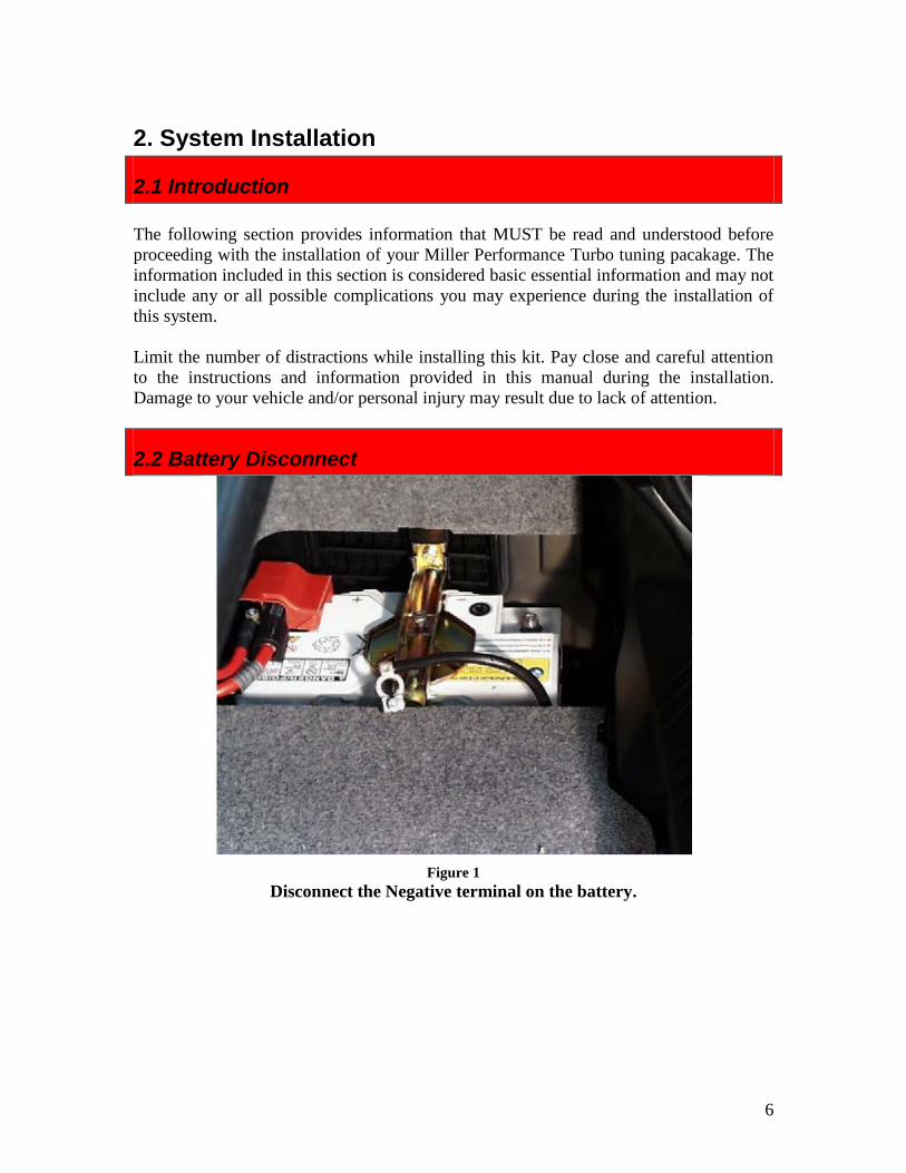
2.2 Battery Disconnect
Figure 1
Disconnect the Negative terminal on the battery.

7
2.3 W.A.R. Chip Installation
This section will guide you through the process of accessing your ECU to install the
W.A.R. Chip and modify a couple wires for your MAF. For more details refer to the
W.A.R. Chip Specific Manual online.
1. A) For e34s open the hood and access the ECU in the E-box on the passenger side
of the engine bay (Upper Side). Using a Philips screwdriver undo the four screws.
B) For E30s open the glove box and above a false ceiling you will find your ECU
mounted by four 10mm fasteners.
2. Unplug and remove the ECU from its compartment.
3. Open the ECU. There are tabs around the bottom of the cover. As well your ECU
may have 4 torx bolts to undo on the top side of the ECU. Remove the Chip in the
ECU and replace it with the W.A.R. Chip.

8
2. 4 MAF Install
This section will guide you through the process of accessing your ECU harness to modify
two ECU wires.
Figure 2
1. Use a small Philips to remove the three small screws on the back to the ECU plug
connector.
2. After the removal of the three screws, carefully pry, with a flat screw driver, the
black backing, back and off the ECU plug. Don’t lose the rubber ring around the
ECU plug.
3. Once you have successfully removed the harness from its black casing you should
end up with something like this
Figure 3
4. Once you have the cover pulled back you are now ready to re-route a few wires.

9
2. 5 ECU Retrofit (Acquiring 12v Signal)
Don’t be intimidated by this procedure. It involves two wires and a small bit of soldering.
Be sure to read and completely understand this section. It is very important to find the
correct wires and pin locations. Otherwise you vehicle could run poorly or not at all.
READ THIS SECTION SLOWLY AND
CAREFULLY! 1. Locate the following pins (make note of which color each pin is):
a. Pin 37 (Red/Blue)
b. Pin 12 (Grey/White)
2. Take the Grey/White wire and cut near the connector. Take the Grey/White wire
and create a ‘T’ soldering it into the wire coming out of pin 37. The below picture
illustrates this step. Note, your Tee’ing the portion of pin 12 that leads to the
engine bay.
Figure 4
3. After the solder is cool lightly pull on the connection to ensure it is going to hold
up. Using some electrical tape or shrink tube, cover the new connection tightly.
4. You can now put the ECU plug back together. Remember to screw the three small
Philips screws back in.
5. Extend the wires for the MAF sensor connector to reach the passenger side
headlight area. This is required as the MAF must be used in DRAW THROUGH.

10
2.6 Variable Closed Loop Control (Highly recommended)
If you opted to use the Miller Variable Closed Loop Control system, you will need to set
up the included wideband gauge and WAR Chip properly for the VCLC to function
properly. The benefits of the VCLC system are incredibly stable and consistent air fuel
ratios under boost regardless of temperature boost level, methanol use etc. The VCLC
system uses the power for the factory ECU to constantly monitor and maintain a target air
fuel ratio in boost. The factory ECU and control algorithms do not offer this and one can
only achieve these results with the VCLC!
1. Refer to the AEM Failsafe Wideband manual for generic installation of power and
ground etc.
2. Refer to the diagram on the next page to integrate the VCLC system features:
a. Cut the TCM knob off of the loom.
b. Take the BLUE wire from the AEM gauge and connect it into the RED
wire on the WAR Chip Tune control module loom.
c. Take the brown AEM wire and ground it to any suitable ground wire or
chassis ground.
Figure 5

11
When you set up the WAR Chip, you must place the tunes in the following position:
Tune 1: Base tune with desired BOOST AFR active
Tune 2: Base tune with desired BOOST AFR active
Tune 3: Base tune with desired BOOST AFR active
Default: Base tune with normal 14.7 AFR active
2.6 VCLC Configuration
To set the trigger for the wideband AFR target switch, plug the AEM gauge into your
computer and run the AEM communication software. Configure your gauge to match the
picture below.

12
2.7 Injector Installation
Installing your injectors is quite easy. Make sure you are working in an environment
without open flames. This should be obvious – but trust us, you’d be surprised…
In this section we will offer some tips on the replacement process.
1) Unbolt the plastic injector harness.
2) Unbolt the fuel rail and gently remove the injectors from their ports as an entire
unit.
3) Now you should have the fuel rail with injectors still attached loose and free to
move around slightly. Carefully remove the first injector by releasing the retainer.
Use a rag to shield where the injector meets the fuel rail. The rail is pressurized so
the rag will catch the fuel from the first injector.
4) Now that the pressure and first injector has been relieved you can remove the
other 5.
5) Clean the injector mating surface and install new injectors into the rail.
6) Reassemble the fuel rail and wiring assembly.
For more detailed instructions please visit this great link:
http://www.pelicanparts.com/BMW/techarticles/E36-Injector-Replacement/E36-Injector-
Replacement.htm

13
3. Drive your Vehicle
3.1 Initial Start up
Remember to connect you battery before you reassemble and start your vehicle. Once
you have connected the battery you will be ready to test your newly installed items.
**Note: This is a base tune. For the sake of your wallet, use caution when boosting.
We recommend setting your boost level around 8 to 10 PSI to start for “checking”
purposes. Call us if you have any strange issues or concerns immediately.
DO NOT BAG ON THE CAR until you have verified the tune at a dyno.
Your car should run well on the base tune out of boost. Once you are ready to dial in your
tune, call and make an appointment with us so that we can tune you over email while at
the dyno. After the tune is confirmed and we are happy with the power and AFR, go have
some fun your car should haul!
3.2 Troubleshooting
If your car hasn’t smoothed out after a 10 minutes of driving you may need to check
some things.
1. Ensure MAF is plugged in correctly IN FRONT of the turbo.
2. Ensure you have no boost leaks. Blow off valves to Atmosphere are not
supported.
3. Ensure you are using the correct base tune.
4. Ensure your injectors all plugged into the injector harness securely.
If you cannot resolve the problem please phone us and we will help walk you through a
solution. You can reach us at our normal toll free number, 855 269 8863 or email
Published January 25, 2015 by, Brody Saari; Photos taken by: Brody Saari, Dan Miller. Copyright 2015. All rights reserved.
Any unauthorized reproduction of this document or any part of, for use other than that of original owners’ application is
prohibited. Miller Performance Ltd. 2015
209KSHU09.3.ASP93.15