m4 corridor around newport - public inquiry server)bailey.persona-pi.com/public-inquiries/m4 -...
TRANSCRIPT

M4 Corridor around Newport Approval in Principle – SBR-2000 Llandevenny Railway Underbridge

Welsh Government
M4 Corridor around Newport
Approval in Principle – SBR-2000 Llandevenny Railway Underbridge
M4CaN-DJV-SBR-Z5_2000-RP-CB-0001
P02 | 12 December 2016
This report takes into account the particular
instructions and requirements of our client.
It is not intended for and should not be relied
upon by any third party and no responsibility
is undertaken to any third party.
Job number 242707
CVJV/DJV
3rd
Floor
Longcross Court,
47 Newport Road,
Cardiff
CF24 0AD

Welsh Government M4 Corridor around NewportApproval in Principle – SBR-2000 Llandevenny Railway Underbridge
Contents
Page
1 Highway Details 3
2 Site Details 3
3 Proposed Structure 3
4 Design Criteria 12
5 Structural Analysis 16
6 Geotechnical Conditions 19
7 Check 20
8 Drawings and Documents 21
9 The Above is Submitted for Acceptance 22
10 The Above is Agreed Subject to the Amendments and Conditions Shown Below 23
Appendix A – List of the Relevant Documents from the TAS 25
Appendix B – Drawings 38
Appendix C – Form C Geotechnical Summary Sheet 39
Appendix D - CDM Hazard Log 42
Appendix E – Idealised Structure Diagrams 46
Appendix F – Schedule of Eurocode Options and Choices 48

Welsh Government M4 Corridor around NewportApproval in Principle – SBR-2000 Llandevenny Railway Underbridge
M4CaN-DJV-SBR-Z5_2000-RP-CB-0001 | P02 | 12 December 2016
\\COSTPW01ICS01\ICS_WORKIN_DIR\1257\7920_30\M4CAN-DJV-SBR-Z5_2000-RP-CB-0001.DOCX
Page 3
1 Highway Details
1.1 Type of highway
Over: Over structure (Proposal): New M4 (three-lane) Motorway
Under: South Wales Main Line Railway (ELR: SWM2, 151 m 60 ch approx.)
1.2 Permitted traffic speed
Over Structure: 70 mph
Under Structure: 90 mph Main Lines; 40 mph Relief Line
1.3 Existing restrictions
A boundary of the Gwent Levels – Redwick and Llandevenny Site of Special Scientific Interest (SSSI) runs parallel to the southern abutment, approximately 5
metres to the south.
There is an existing highway bridge over the railway approximately 95 metres to the east of the proposed structure. An existing railway signal gantry spans over the railway approximately 33.5 metres to the east of the proposed structure.
2 Site Details
2.1 Obstacles crossed
South Wales Main Line Railway lines, comprising 4No. tracks – Up Main, Down
Main, Up Relief and Down Relief.
Green Lane, a non-motorised user route will also pass under the structure, adjacent to the northern abutment.
3 Proposed Structure
3.1 Description of structure and design working life
SBR-2000 Llandevenny Railway Underbridge will carry the new M4 Corridor around Newport over the South Wales Main Line in the Llandevenny area, south of Junction 23A of the existing M4. The proposed structure is a single span
precast concrete beam with reinforced concrete deck slab fully integral with reinforced concrete abutments.
A Non-motorised user route will also pass under the structure, adjacent to the
northern abutment. There is no known requirement for a footpath on the south side.
The bridge superstructure and substructure are to have a design working life of 120 years, category 5 in accordance with BS EN 1990, UK National Annex NA
2.1.1 and IAN 124/14(W), table A.1.

Welsh Government M4 Corridor around NewportApproval in Principle – SBR-2000 Llandevenny Railway Underbridge
M4CaN-DJV-SBR-Z5_2000-RP-CB-0001 | P02 | 12 December 2016
\\COSTPW01ICS01\ICS_WORKIN_DIR\1257\7920_30\M4CAN-DJV-SBR-Z5_2000-RP-CB-0001.DOCX
Page 4
Bridge parapets to have a design working life of 50 years, category 2 in accordance with BS EN 1990, UK National Annex NA 2.1.1 and IAN 124/14(W), table A.1.
3.2 Structural type
The structure will be formed of 20No. precast pre-stressed U12 type concrete beams at 1.975m centres, with 200mm thick in-situ concrete deck. The deck will be integral with the reinforced concrete abutments.
The wingwalls will be constructed from reinforced earth with vertical concrete
facing panels. Polyurethane joint sealant will be used between the reinforced concrete abutments wall and wingwalls.
3.3 Foundation type
The deck is supported by reinforced concrete abutments on reinforced concrete
bored piles at South side and spread foundation at the North side
The reinforced earth wing walls will be founded on a driven piled load transfer platform on the south side that also forms the embankment foundation. On the north side the reinforced earth walls will be founded in the rock.
3.4 Span arrangements
The pre-stressed concrete beam deck is to be a single span structure of approximately 29.9m clear skew span between faces of abutments (29 degree skew angle).
3.5 Articulation arrangements
The pre-stressed concrete beams will behave as simply supported beams during
construction. Once the top end of the abutments and the concrete deck are cast in place and have gained strength, the deck will act integrally with the abutments and will develop a level of fixity at the ends.
3.6 Proposed Classes and levels
3.6.1 Consequence class
Consequence Class 2 (CC2) in accordance with BS EN 1990 clause B3.1, UK National Annex clause NA 3.2 and IAN 124/14(W) Table A.2.
3.6.2 Reliability class
Reliability Class 2 (RC2) in accordance with BS EN 1990 clause B3.3 and IAN
124.14(W) Table A.2. KFI = 1.0.
3.6.3 Inspection level
Inspection Level 2 (IL2) in accordance with BS EN 1990 cl. B5, Table B.5 and IAN 124/14(W) Table A.2.

Welsh Government M4 Corridor around NewportApproval in Principle – SBR-2000 Llandevenny Railway Underbridge
M4CaN-DJV-SBR-Z5_2000-RP-CB-0001 | P02 | 12 December 2016
\\COSTPW01ICS01\ICS_WORKIN_DIR\1257\7920_30\M4CAN-DJV-SBR-Z5_2000-RP-CB-0001.DOCX
Page 5
3.7 Road restraint systems requirements
Over Structure: The precast concrete parapets of the bridge will be 1.85 m high solid H4a Very High Containment level and will transition into the N2 W2 safety
barriers used on the approaches to the bridge. A concrete step barrier (CSB) will be provided in the central reserve.
Edge protection to the wingwalls will consist of a strained wire fence to HCD Drawing H13.
3.8 Proposed arrangements for future maintenance and inspection
3.8.1 Traffic management
Principal Inspections of the top of the bridge will require lane closures of the M4. Inspections to the soffit of the bridge above the railway tracks and within 3 m of
the running rails will require track possessions.
3.8.2 Access
Authorised Network Rail vehicle access points are available:
a) To the northern side of the tracks, at SWM2 152 m 0 ch.
b) To the southern side of the tracks, at SWM2 151 m 40 ch.
Access for inspection of the northern abutment and wing walls would be via the Non-Motorised User route from Green Moor Lane, as this abutment is outside the proposed Network Rail palisade fencing.
Access to the southern abutment and part of the wing walls would be via Network
Rail boundary and would require the necessary permissions, PPE and safety personnel as specified by Network Rail and Rail Group Standards. Access to wing walls outside the Network Rail boundary can be from the maintenance track
at the foot of the embankment.
3.9 Environment and sustainability
The design proposed addresses sustainability issues as follows:
a) Integral deck construction with abutments will minimise inspection and maintenance requirements, particularly adjacent the railway tracks
b) The structure is a new bridge and will be constructed before the highway network is open to use in the area. That will minimise traffic disruption and reduce the CO2 output resulting from the any delays.
c) GGBS cement replacement will be used in concrete mixes which reuses a
by-product from iron blast furnaces which is abundant in South Wales. GGBS also improves the durability of concrete by reducing its permeability and increasing its resistance to chloride ingress and
chemical attack.

Welsh Government M4 Corridor around NewportApproval in Principle – SBR-2000 Llandevenny Railway Underbridge
M4CaN-DJV-SBR-Z5_2000-RP-CB-0001 | P02 | 12 December 2016
\\COSTPW01ICS01\ICS_WORKIN_DIR\1257\7920_30\M4CAN-DJV-SBR-Z5_2000-RP-CB-0001.DOCX
Page 6
d) Reinforced soil walls provide a proven economical solution with minimal use of off-site materials. It is also proposed that 6I/6J materials will be obtained from site won materials.
e) The structure span allows for the inclusion of a Non-Motorised User Route, which will allow pedestrians to cross under the proposed M4CaN with minimal detour.
3.10 Durability, materials and finishes
3.10.1 Concrete Classes
Structural Element
Co
mp
res
siv
e
Str
en
gth
Cla
ss
Surface
Exposure Class
Δc
Nominal cover for XC/XD/XF (mm)
XC XD XF
In-situ Deck Slab
C40/50
Exposed surfaces
XC4 XD3 XF4 15 45/45/60
Surfaces covered by waterproofing
XC3 - - 10 40
Precast Beams
C50/60
Exposed surfaces
XC3 XD1 - 5 35
Internal surfaces XC3 - - 5 35
Precast Parapet and copings
C40/50 Exposed surfaces
XC3 XD1 XF2 5 60/60/60
Abutments
C40/50
Exposed surfaces
XC3 XD1
XD3 XF2 15
45/50
60/60
Buried surfaces XC2 XD2 XF1 15 40/55/55
Wingwall C40/50
Buried surfaces XC2 XD2 XF1 15 40/55/55
Exposed surfaces
XC3 XD3 XF2 15 45/60/60
Piles C32/40 Buried surfaces XC2 XD2 - N/A 75/75/75
Pile Cap and Spread Foundation
C32/40 Buried Surfaces XC2 XD2 - 15 40/55/55
Precast wall panels
C40/50
Exposed surfaces
XC3 XD1 XD3
XF4 5 35/40 50/50
Buried surfaces XC2 XD2 XF1 5 30/45/45
Levelling pad
C32/40 Buried surfaces XC2 XD2 - 15 N/A
.

Welsh Government M4 Corridor around NewportApproval in Principle – SBR-2000 Llandevenny Railway Underbridge
M4CaN-DJV-SBR-Z5_2000-RP-CB-0001 | P02 | 12 December 2016
\\COSTPW01ICS01\ICS_WORKIN_DIR\1257\7920_30\M4CAN-DJV-SBR-Z5_2000-RP-CB-0001.DOCX
Page 7
Blinding concrete is to be Class ST1 subject to satisfying design chemical class for ground water.
3.10.2 Reinforcement
Ribbed bars to BS 4449:2005, BS 8666 and BS EN 10080.
Characteristic yield strength fyk = 500MPa; Grade B500B unless otherwise stated.
3.10.3 Stainless Steel
3.10.4 Not applicable.Prestressing Strand
The strand size and type shall be 15.7mm diameter 7-wire super strands with nominal tensile strength of 1860 N/mm2 and relaxation class 2. Strands are
typically prestressed to 209kN per strand. The material of prestressing strands shall be in accordance with BS EN 10138-3. Prestressing steel Part 3 – Strand and its UK National Annex.
3.10.5 Concrete finish classes
Structural Element Finish Class
Precast parapet F4
Exposed abutments F4, U3
Buried faces of abutments / Pile caps / Spread foundation F1, U1
Surfaces to be waterproofed F2, U4
Precast beams F5
Precast coping at top of reinforced earth wall F4
3.10.6 Silane finish
In areas affected by de-icing salts, low toxicity hydrophobic impregnate and freeze/thaw aggregates are to be employed in accordance with BD 43/03 provided there are no environmental constraints. There are no environmental
constraints identified at this stage.
3.10.7 Structural steel
Not applicable.
3.10.8 Paint system
Not applicable.
3.10.9 Waterproofing

Welsh Government M4 Corridor around NewportApproval in Principle – SBR-2000 Llandevenny Railway Underbridge
M4CaN-DJV-SBR-Z5_2000-RP-CB-0001 | P02 | 12 December 2016
\\COSTPW01ICS01\ICS_WORKIN_DIR\1257\7920_30\M4CAN-DJV-SBR-Z5_2000-RP-CB-0001.DOCX
Page 8
Proprietary spray applied waterproofing system to BD 47/99 and IAN 96/07 (W). The remainder of the buried parts of the structure are to have two coats of bituminous paint or equivalent, to SHW clause 2004.
3.10.10 Surfacing
Minimum 120 mm carriageway surfacing (including waterproofing) in accordance with BD 47/99 and SHW.
3.10.11 Lighting
The M4 Corridor around Newport is only to be lit at junctions. No road lighting is
required across the structure.
3.10.12 Bearings
Not applicable
3.10.13 Joints
Saw cut joints will be provided in the surfacing behind the abutments to accommodate any difference in movement between the fill and the integral abutments.
3.10.14 Drainage
Back of Wall Drainage
The abutments will be provided with a positive back of wall drainage system. The reinforced earth wingwalls will be provided with a front wall drainage to collect water discharged from the joints of the panels. These two drainage systems will
meet at the catch pit before discharging into a soakaway. The locations of soakaway will be designed at detailed design stage. Main deck surface drainage shall not tie into the back of wall drainage but subsurface drains can.
Deck Surface and Subsurface Drainage
Where positive surface drainage is required on bridge decks this shall be provided using a combined kerb drain system, such as Brigdek or similar. The combined surface drain shall also be capable of collecting subsurface run-off but
the flow need not be separated. Inspection points and flushing boxes will be provided. The bridge deck drainage system is to be connected to the highway drainage system at the low point of the bridge end.
Bridge decks (including verge areas) shall have a minimum cross fall of 2.5%. Verge areas shall drain towards the carriageway and not toward the edge beam.
The highway drainage to the north of the bridge needs to be taken across to the balancing ponds south of the railway. The highway drainage pipe 450mm
diameter will pass through the bridge beams inside a 600mm sleeve, one under the eastbound verge and the second under the westbound side of the central reserve. The plastic sleeve will be sealed into the concrete diaphragm in order to
prevent leakage onto the railway. Carriageway drainage will use highway drainage channels. The drainage channels will be intercepted before the bridge in order to minimise water that flows onto the bridge.

Welsh Government M4 Corridor around NewportApproval in Principle – SBR-2000 Llandevenny Railway Underbridge
M4CaN-DJV-SBR-Z5_2000-RP-CB-0001 | P02 | 12 December 2016
\\COSTPW01ICS01\ICS_WORKIN_DIR\1257\7920_30\M4CAN-DJV-SBR-Z5_2000-RP-CB-0001.DOCX
Page 9
The void inside each U beam will have a drain outlet in front of the south abutment diaphragm.
Kerbs will be provided along each verge in accordance with TD 19/06 cl 4.25
3.10.15 Structural fill
Structural fill to be Class 6N or 6P. Where reinforced earth walls are used it will be Class 6I or 6J in preference to class 6N or 6P.
Characteristic fill material properties are provided below and will be verified on site during construction.
Property Value Reference
Unit Weight γ = 19 kN/m3 BS EN1991-1-1 Table A6
Poisson’s Ratio υ = 0.3
Cohesion c = 0
Angle of Friction Φ’ = 38° Characteristic value for 6N granular structural fill (Max Φ’ = 43°)
3.11 Risks and hazards considered for design, execution, maintenance and demolition.
Details of the hazards identified, associated design mitigation measures and
residual hazards are recorded in Appendix D. Each hazard listed has an associated item in the scheme CDM Hazard Log which is regularly reviewed by the CDM Principal Designer and project team.
A summary of key hazards is given below:
a) Temporary stability during backfill to abutments / wingwalls / reinforced earth walls. Lateral earth pressure leading to abutment / wingwall / reinforced earth wall collapse
b) Risk of ground conditions varying from those assumed in design leading to settlement / damage to structure
c) Demolition of precast beams causing snapping of prestressed tendons
d) Temporary stability of precast beams under weight of wet concrete,
leading to collapse
e) Construction and demolition adjacent to Great Western Main Line railway
3.12 Estimated cost of proposed structure together with other structural forms considered (including where appropriate proprietary manufactured structure), and the reasons for their rejection (including

Welsh Government M4 Corridor around NewportApproval in Principle – SBR-2000 Llandevenny Railway Underbridge
M4CaN-DJV-SBR-Z5_2000-RP-CB-0001 | P02 | 12 December 2016
\\COSTPW01ICS01\ICS_WORKIN_DIR\1257\7920_30\M4CAN-DJV-SBR-Z5_2000-RP-CB-0001.DOCX
Page 10
comparative whole life costs with dates of estimates)
The following structural forms were considered for the proposed Llandenvenny
railway underbridge:
a) Network Rail Standard Design modular overbridge - The width and increased span of the proposed bridge exceeds the standard design limit. Although included in Network Rail’s standard design suite, this bridge is considered over-complicated with numerous construction issues.
b) Steel plate girder composite ladder deck - Network Rail prefer concrete overbridges to steel as railway possessions are required to maintain (paint) steel bridge soffits. Where weathering steel can be used bonding and earthing will still be required for OLE under the soffit. Therefore a concrete bridge deck is considered the most economical whole life cost.
c) Multi-girder composite deck - A precast concrete solution was considered
more economical and would have a lower risk profile. Network Rail prefer concrete overbridges to steel as railway possessions are required to maintain (paint) steel bridge soffits. Even where weathering steel is used Network Rail prefer concrete bridges. Weathering steel bridges with earth bonding to inspected and maintain as consider by NR to require more frequent possessions. The construction of concrete bridges also is considered lower risk in terms of the interface with Network Rail and ensuring that structures remain isolated during each step of construction. Therefore a concrete bridge deck is considered the most economical whole life cost.
The table below gives a summary of cost estimates for each option.
Option Capital Cost Operational Cost Whole Life Cost
Preferred option £3.7m £550k £4.26m
a) Not feasible - -
b) £3.5m £0.88m £4.38m
c) £3.8m £0.95m £4.75m
For the purpose of this estimate, it has been assumed that the operational costs are 15% of the capital costs for concrete option and 25% for steel composite
option to include the cost of possessions. The steel composite bridges with earth bonding require more frequent possessions for inspection and maintenance. The cost estimates are dated 29-11-2016. The operational cost is only based on a
percentage of the capital cost from previous experience. The whole life cost is the sum of capital cost and operational cost.
3.13 Proposed arrangements for construction
3.13.1 Construction of structure

Welsh Government M4 Corridor around NewportApproval in Principle – SBR-2000 Llandevenny Railway Underbridge
M4CaN-DJV-SBR-Z5_2000-RP-CB-0001 | P02 | 12 December 2016
\\COSTPW01ICS01\ICS_WORKIN_DIR\1257\7920_30\M4CAN-DJV-SBR-Z5_2000-RP-CB-0001.DOCX
Page 11
Erection of the precast concrete beams will require lifting by crane. Details of the lifting scheme will be considered at the construction phase. Care will need to be taken to ensure that all lifting plans consider the proximity of the railway tracks,
the adjacent road bridge any nearby services and surrounding land uses.
The general construction sequence will be as follows:
Under Normal Train Movements
a) Excavation of ground to piling platform level
b) Installation of piles and breakdown to pile cap level
c) Construction of abutments
d) Partial backfill behind abutments including reinforced earth wingwall elements
Under Track Possession
e) Erection of precast concrete beams by crane
f) Casting main beam connections to abutments
g) Casting of insitu deck over beams
Under Normal Train Movements
h) Completion of backfilling of abutments and installation of reinforced earth / soil wing walls and retaining walls
i) Application of waterproofing and completion of road surfacing works
j) General finishes including cladding, erosion protection, access tracks and hard standings
3.13.2 Traffic management
The M4CaN is an offline bypass route thus construction of this bridge will not
require any traffic management to the existing M4.
Railway possessions will be required for works over and adjacent to the railway lines.
3.13.3 Service diversions
None.
3.13.4 Interface with existing structures
Designed to span over the existing railway signal gantry and be clear of the gantry foundations. Network Rail line side cabinets will require relocation.

Welsh Government M4 Corridor around NewportApproval in Principle – SBR-2000 Llandevenny Railway Underbridge
M4CaN-DJV-SBR-Z5_2000-RP-CB-0001 | P02 | 12 December 2016
\\COSTPW01ICS01\ICS_WORKIN_DIR\1257\7920_30\M4CAN-DJV-SBR-Z5_2000-RP-CB-0001.DOCX
Page 12
4 Design Criteria
4.1 Actions
4.1.1 Permanent actions
Permanent Actions will be applied using the recommended values in BS EN
1991-1-1 and the associated National Annex. The values given in the table below clarify the density and action that will be used in design where a range is provided in BS EN 1991-1-1:
Structural concrete 25 kN/m3 Concrete infill 24 kN/m3 Surfacing 23 kN/m3 Soil infill (class 6N/6P material), typical value given 19 kN/m3
4.1.2 Snow, Wind and Thermal actions
Snow actions will be disregarded in accordance with the UK National Annex to
BS EN 1991-1-3, clause NA.4.1.1.
Wind actions will be determined in accordance with BS EN 1991-1-4, the UK National Annex and PD 6688-1-4.
The following fundamental basic wind velocity (before the altitude correction) will
be used:
• Vb,map = 22 m/s
Wind and thermal actions will not be used in the same design combination in accordance BS EN 1990, cl.A2.2.2(6).
Thermal actions will be applied to the structure in accordance with BS EN 1991-
1-5 and the UK National Annex.
The following minimum and maximum shade air temperatures will be used (before adjustment for annual probability of being exceeded p other than 0.02):
• Tmin = -12°C
• Tmax = 32°C
4.1.3 Actions relating to normal traffic under AW regulations and C&U regulations
Load Model 1 and 2 in accordance with BS EN 1991-2 and UK National Annex.
4.1.4 Actions relating to General Order Traffic under STGO regulations
Load model 3 will be considered in accordance with BS EN 1991-2. Special
vehicles (LM 3) to be considered as follows:
a) SV 80
b) SV 100
c) SV 196

Welsh Government M4 Corridor around NewportApproval in Principle – SBR-2000 Llandevenny Railway Underbridge
M4CaN-DJV-SBR-Z5_2000-RP-CB-0001 | P02 | 12 December 2016
\\COSTPW01ICS01\ICS_WORKIN_DIR\1257\7920_30\M4CAN-DJV-SBR-Z5_2000-RP-CB-0001.DOCX
Page 13
4.1.5 Footway or footbridge variable actions
Actions on footways in accordance with BS EN 1991-2 clause 5.3.2 shall be applied at verges.
4.1.6 Actions relating to Special Order Traffic, provision for exceptional abnormal
indivisible loads including location of vehicle track on deck cross-section
Not applicable.
4.1.7 Accidental actions
Accidental vehicle loading will be applied to the verges in accordance with BS EN
1991-2 clause 4.7.3.
Superstructure will be designed to withstand the impact loading described in clause 4.3.2 of BS EN 1991-1-7, associated UK National Annex and clause 2.8 of PD 6688-1-7.
Substructure will not be designed for the derailment loading where lateral clearance between the substructure and the running rail is at least 4.5m (NR/L3/CIV/020 clause 14.4).
4.1.8 Action during construction
Actions during construction will be calculated in accordance with BS EN 1991-1-6 and the associated National Annex. The actions during execution will consider the construction sequence as per buildability report and may change in due
course.
Refinements or amendments to the options and choices will not be known until the detailed design stage. These may include restriction of free construction
loads, the specification of fixed loads, other specialist controls, the use of special construction vehicles/equipment on the structure, changes to the return periods for the calculation of design loads, or the specification of different loads or
factors.
These controls, restrictions or amendments will be confirmed at detailed design stage and recorded in the Project Specification, Drawings or Contractor’s Method Statement as appropriate.
4.1.9 Any special action not covered above
Structures will not be designed for seismic actions described in BS EN 1998-2 and the UK National Annex.
Fatigue Load Model 3 (single vehicle model) in accordance with EN 1991 shall be
applied.
4.2 Heavy or high load route requirements and arrangements being made to preserve the route, including any provision for future heavier loads or future widening
The M4 Corridor around Newport is not on a Heavy or High Load Route.

Welsh Government M4 Corridor around NewportApproval in Principle – SBR-2000 Llandevenny Railway Underbridge
M4CaN-DJV-SBR-Z5_2000-RP-CB-0001 | P02 | 12 December 2016
\\COSTPW01ICS01\ICS_WORKIN_DIR\1257\7920_30\M4CAN-DJV-SBR-Z5_2000-RP-CB-0001.DOCX
Page 14
4.3 Minimum headroom provided
The minimum headroom above rail level to structure soffit will be 4.78m +S. This is subject to confirmation from Network Rail of the minimum requirement for
electrification of the Main Line. The existing signal gantry has 4250mm Horizontal clearance and 5250 headroom from Up relief line; 3230mm horizontal clearance and headroom 5225mm from Down relief line. A vertical clearance dimension is
shown on the General Arrangement drawing. (Refer to Appendix B)
4.4 Authorities consulted and any special conditions required
The following parties will be consulted regarding the relevant issues:
Statutory Consultees:
a) Welsh Government Technical Approval Authority (TAA)
b) Welsh Government Network Management Operations Team
c) Network Rail
d) Natural Resources Wales (NRW)
e) Monmouthshire County Council (MCC)
Other consultees
a) Design Commission for Wales (DCfW)
b) Statutory Undertakers
No special conditions have been imposed by these parties at this time.
The bridge is proposed to span over the planned Network Rail (NR) Overhead Line Equipment (OLE) fixings and supports. The NR electrification design is not
yet complete but will be checked to ensure that there is adequate separation, when it becomes available.
4.5 Standards and documents listed in the Technical Approval Schedule
Refer to Appendix A.
4.6 Proposed Departures relating to departures from standards given in 4.5
None

Welsh Government M4 Corridor around NewportApproval in Principle – SBR-2000 Llandevenny Railway Underbridge
M4CaN-DJV-SBR-Z5_2000-RP-CB-0001 | P02 | 12 December 2016
\\COSTPW01ICS01\ICS_WORKIN_DIR\1257\7920_30\M4CAN-DJV-SBR-Z5_2000-RP-CB-0001.DOCX
Page 15
4.7 Proposed Departures relating to methods for dealing with aspects not covered by standards in 4.5
Not applicable.
4.8 List of record of options and choices (for Categories 2 and 3 checks)
The Eurocode related choices list will be completed as part of the detailed design process and will be distributed to the Category 2 checker.
Refer to Appendix F.

Welsh Government M4 Corridor around NewportApproval in Principle – SBR-2000 Llandevenny Railway Underbridge
M4CaN-DJV-SBR-Z5_2000-RP-CB-0001 | P02 | 12 December 2016
\\COSTPW01ICS01\ICS_WORKIN_DIR\1257\7920_30\M4CAN-DJV-SBR-Z5_2000-RP-CB-0001.DOCX
Page 16
5 Structural Analysis
5.1 Methods of analysis proposed for superstructure, substructure and foundations
The analysis of the superstructure will be carried out by linear elastic methods taking into account the construction sequence and construction loading. Analysis of the deck will be carried out using a 3D grillage space frame analysis with soil
springs at the abutment walls. Local effects in the deck slab will be determined by using Pucher charts. The pre-stressed concrete beams will be designed using hand calculations.
All computer models will be in LUSAS software or equivalent.
5.1.1 Method of analysis for ultimate limit states (excluding fatigue)
The analysis of the structure for ultimate limit state will be by linear elastic methods.
The superstructure will be analysed using a 3-dimensional space frame computer
model. The parapets/vehicle barriers will be included as superimposed dead loads, but will not be modelled. Local wheel load effects will be determined using Pucher charts.
The earth pressure behind the abutment will be applied in accordance with the
method set out in PD 6694-1 Clause 9.4.3. In order to use this method, the requirement of PD6694-1 Clause 9.2.1 that the sway at pile cap level is sufficiently small for at rest pressure to be considered as acting on the pile cap
will be met. Alternatively, LUSAS Winkler Springs will be used to model the soil structure interaction.
The piles of the piled foundation will be modelled as individual equivalent
cantilevers. Piglet, or equivalent, will be used to determine the flexibility matrix of the piles and this will be used to determine the equivalent cantilever length and properties. The spread foundation at the North abutment will be modelled as soil
spring supports by the method described in Hambly’s book “Bridge Deck Behaviour – 2nd Edition”. The sensitivity of varying effective pile length and spring stiffness will be investigated. The soil stiffness values will be given in the
Geotechnical Report.
Reinforced Earth / Soil Walls
The design of reinforced earth / soil structures will be carried out to BS EN 1997-1:2004 using the approach of BS 8006-1:2010 which is compliant with the
Eurocode. Internal wall stability will be checked by use of section 6.6 of BS8006 and the appropriate method will be selected based on the material of the reinforcement element and external stability to section 6.5 of BS8006 taking into
account the recommendations of BS6031:2009.
H4a parapet will be designed as class D of UK NA to BS EN 1991-2:2003.
5.1.2 Method of analysis for serviceability limit States

Welsh Government M4 Corridor around NewportApproval in Principle – SBR-2000 Llandevenny Railway Underbridge
M4CaN-DJV-SBR-Z5_2000-RP-CB-0001 | P02 | 12 December 2016
\\COSTPW01ICS01\ICS_WORKIN_DIR\1257\7920_30\M4CAN-DJV-SBR-Z5_2000-RP-CB-0001.DOCX
Page 17
At the serviceability limit state, verification of the stress levels and deflections and crack widths in concrete will be carried out as specified in BS EN 1992-1-1 and BS EN 1992-2.
Action effects will be evaluated using elastic global analysis and allowing for the effects of shear lag, shrinkage and creep.
5.2 Description and diagram of idealised structure to be used for analysis
5.2.1 Superstructure:
For global analysis, the deck will be idealised as longitudinal members representing the concrete main beams and concrete deck elements, and transverse members representing the transverse concrete deck and cantilevered
deck verge.
For the transient construction stage, the main beams will be designed as simply supported (pre-stress concrete section only). The encased ends of the beams will provide rigid connection to the top of abutments once the deck is cast and gains
sufficient strength.
5.2.2 Substructure:
The substructure is designed as integral with the bridge deck. Vertical members will represent the abutment and pile cap. The piles of the piled foundation will be
modelled as equivalent cantilevers.
5.2.3 Wingwalls:
The reinforced earth wingwalls will be analysed for the load cases as shown in Appendix E with the soil reinforcement strips being checked for pull
out/adherence and rupture. In addition the resistance to sliding of individual elements of the wall will be checked.
For modular block walls using steel strip or geosynthetic reinforcement
The reinforced soil wall is to be considered as a full height reinforced soil wall supporting a carriageway, as per Figure 27 of BS 8006-1:2010 in Appendix E
5.2.4 Refer to Appendix E for diagrams of the idealised structure.
5.3 Assumptions intended for calculation of structural element stiffness
Although the bridge deck is constructed integral with the abutments, a full
moment connection is only achieved in the short term case. Thermal deformation, settlement, creep and shrinkage all cause the pre-stressed beams to pry away from the abutment causing the bridge behaviour to change from a continuous,
built in bridge closer to simply supported.
Analysis methods detailed within ‘Bridge Deck Behaviour – 2nd Edition – 1991’ by E.C. Hambly will be adopted to determine longitudinal and transverse grillage
member stiffness properties. Cracked section properties will be used for the deck slab in the hogging regions.

Welsh Government M4 Corridor around NewportApproval in Principle – SBR-2000 Llandevenny Railway Underbridge
M4CaN-DJV-SBR-Z5_2000-RP-CB-0001 | P02 | 12 December 2016
\\COSTPW01ICS01\ICS_WORKIN_DIR\1257\7920_30\M4CAN-DJV-SBR-Z5_2000-RP-CB-0001.DOCX
Page 18
Element properties for abutments and foundations will be based on uncracked concrete properties.
5.4 Proposed range of soil parameters to be used in the design of earth retaining elements
Values between ka and ko will be chosen to give the worst possible loading combination for the design of a particular structural element where soil pressure is active.
Values of k*, in accordance with PD6694-1, between k0 and kp will be chosen to
give the worse possible loading combination for the design of a particular structural element where the soil pressure is passive.
The backfill to the abutments and wingwalls will be class 6N/6P selected granular
fill. The characteristic angle of friction will be Φ’ = 38°. These limits will be demonstrated by compliance testing.
Characteristic values will be based on Φ’ = 38° for 6I/6J backfill for ka and ko calculations.

Welsh Government M4 Corridor around NewportApproval in Principle – SBR-2000 Llandevenny Railway Underbridge
M4CaN-DJV-SBR-Z5_2000-RP-CB-0001 | P02 | 12 December 2016
\\COSTPW01ICS01\ICS_WORKIN_DIR\1257\7920_30\M4CAN-DJV-SBR-Z5_2000-RP-CB-0001.DOCX
Page 19
6 Geotechnical Conditions
6.1 Acceptance of recommendations of the Geotechnical Design Report to be used in the design and reasons for any proposed changes
The scheme is currently in the preliminary design stage and is supported by a Geotechnical Design Report (GDR) (Key Stage3) issued as Final in November
2016. The GDR (Key Stage 3), in the context of preliminary design presents the proposed design methodologies for the geotechnical elements of the structures on the scheme. The GDR will be updated and further developed
during Key Stage 6 and will provide final detail on the design of geotechnical elements.
In this AIP a Form C (Highway Structure Summary Form) has been included. This provides a summary of the anticipated ground conditions. It is proposed
that the Form C will be updated (if required) and presented as part of the detailed design GDR (Key Stage 6) rather than requiring a reissue of this AIP.
6.2 Summary of design for highway structure in the Geotechnical Design Report
The Form C for this structure is included in Appendix C of this document which provides a summary of the geotechnical design.
6.3 Differential settlement to be allowed for in the design of the structure
Differential settlement will be considered at both ULS and SLS. Differential
settlement will be classified as a permanent action and will be modelled as 25mm for design purposes.
The structure will be designed to accommodate 10mm differential settlement
between the abutments after the construction.
The structure will be designed to accommodate 10mm short term and 15mm long term differential settlement after the construction of the deck between the abutments. Differential settlement between abutments and wing walls will be
taken as 10mm.
6.4 If the Geotechnical Design Report is not yet available, state when the results are expected and list the sources of information used to justify the preliminary choice of foundations
The Geotechnical Design Report (Key Stage 3) was issued as Final in November 2016 and it will be updated during Key Stage 6 as the designs are developed.
The GDR (Key Stage 3) is based on the Ground Investigation Report (GIR) as
issued in February 2016. The GIR sets out the available information in terms of ground investigation for the Scheme. Data referred to and summarised in the

Welsh Government M4 Corridor around NewportApproval in Principle – SBR-2000 Llandevenny Railway Underbridge
M4CaN-DJV-SBR-Z5_2000-RP-CB-0001 | P02 | 12 December 2016
\\COSTPW01ICS01\ICS_WORKIN_DIR\1257\7920_30\M4CAN-DJV-SBR-Z5_2000-RP-CB-0001.DOCX
Page 20
GIR includes borehole logs, trial pit records, the results of in situ and laboratory testing and details of groundwater encountered. This information has been used to prepare the Form C included in this AIP which summarises the
preliminary foundation choice.
7 Check
7.1 Proposed Category and Design Supervision Level
Category 2 to BD2/12. Design Supervision level DSL2.
7.2 If Category 3, name of proposed Independent Checker
Not applicable.
7.3 Erection proposals or temporary works for which Types S and P Proposals will be required, listing structural parts of the permanent structure affected with reasons
Not applicable.

Welsh Government M4 Corridor around NewportApproval in Principle – SBR-2000 Llandevenny Railway Underbridge
M4CaN-DJV-SBR-Z5_2000-RP-CB-0001 | P02 | 12 December 2016
\\COSTPW01ICS01\ICS_WORKIN_DIR\1257\7920_30\M4CAN-DJV-SBR-Z5_2000-RP-CB-0001.DOCX
Page 21
8 Drawings and Documents
8.1 List of drawings (including numbers) and documents accompanying the submission
Title Drawing No.
SBR-2000 Llandevenny Railway Underbridge GA (sheet 1 or 2)
M4CaN-DJV-SBR-Z5_2000-DR-CB-0002
SBR-2000 Llandevenny Railway Underbridge GA (sheet 2 or 2)
M4CaN-DJV-SBR-Z5_2000-DR-CB-0003

Welsh Government M4 Corridor around NewportApproval in Principle – SBR-2000 Llandevenny Railway Underbridge
M4CaN-DJV-SBR-Z5_2000-RP-CB-0001 | P02 | 12 December 2016
\\COSTPW01ICS01\ICS_WORKIN_DIR\1257\7920_30\M4CAN-DJV-SBR-Z5_2000-RP-CB-0001.DOCX
Page 22
9 The Above is Submitted for Acceptance
Signed:
XRob Wheatley
Chief Engineer
Name: R N Wheatley __________________
Design Team Leader
Engineering Qualifications BEng CEng FICE _______________
For and on behalf of
Name of organisation DJV
Date: _____________________________

Welsh Government M4 Corridor around NewportApproval in Principle – SBR-2000 Llandevenny Railway Underbridge
M4CaN-DJV-SBR-Z5_2000-RP-CB-0001 | P02 | 12 December 2016
\\COSTPW01ICS01\ICS_WORKIN_DIR\1257\7920_30\M4CAN-DJV-SBR-Z5_2000-RP-CB-0001.DOCX
Page 23
10 The Above is Agreed Subject to the Amendments and Conditions Shown Below
Signed: _____________________________
Name: _____________________________
Position held: _____________________________
Engineering Qualifications: _____________________________
TAA
Date: _____________________________

Welsh Government M4 Corridor around NewportApproval in Principle – SBR-2000 Llandevenny Railway Underbridge
M4CaN-DJV-SBR-Z5_2000-RP-CB-0001 | P02 | 12 December 2016
\\COSTPW01ICS01\ICS_WORKIN_DIR\1257\7920_30\M4CAN-DJV-SBR-Z5_2000-RP-CB-0001.DOCX
Page 24
Appendices

Welsh Government M4 Corridor around NewportApproval in Principle – SBR-2000 Llandevenny Railway Underbridge
M4CaN-DJV-SBR-Z5_2000-RP-CB-0001 | P02 | 12 December 2016
\\COSTPW01ICS01\ICS_WORKIN_DIR\1257\7920_30\M4CAN-DJV-SBR-Z5_2000-RP-CB-0001.DOCX
Page 25
Appendix A – List of the Relevant Documents from the TAS
TECHNICAL APPROVAL SCHEDULE “TAS” (August 2014) SCHEDULE OF DESIGN DOCUMENTS RELATING TO DESIGN OR ASSESSMENT OF HIGHWAY BRIDGES AND STRUCTURES (All documents are taken to include revisions current at date of this TAS)
A.1.1 BRITISH STANDARDS
BS 5930: 1999+ A2:2010
Site Investigations [Amendment No. 1 December 2007 and 2 Aug 2010]. Partially replaced by BS EN ISO 22475-1:2006, BS EN ISO 14688-1:2002, BS EN ISO 14689-1:2003, BS EN 1997-2:2007, BS EN ISO 14688-2:2004+A1:2013, BS EN ISO 22476-2:2005+A1:2011, BS EN ISO 22476-3:2005+A1:2011, BS EN ISO 22282-1:2012, BS EN ISO 22282-2:2012, BS EN ISO 22282-3:2012, BS EN ISO 22282-4:2012, BS EN ISO 22282-5:2012, BS EN ISO 22282-6:2012, BS EN ISO 22476-1:2012, BS EN ISO 22476-5:2012, BS EN ISO 22476-7:2012, BS EN ISO 22476-4:2012
BS 6031: 2009 Code of practice for earthworks [Corrigendum August 2010]
BS 6744:2001+A2:2009 Stainless steel bars for the reinforcement of and use in concrete. Requirements and test methods
BS 7818: 1995 Specification for Pedestrian Restraint Systems in Metal AMD15047, AMD16540
BS 8006-1:2010
Code of practice for strengthened/reinforced soils and other fills
BS 8006-2: 2011 Code of practice for strengthened/reinforced soils Soil nail design. Corrigenda Sept and Nov 2013
BS 8500-1:2006+A1:2012 Concrete – Complementary British Standard to BS EN 206-1 – Part 1: Method of specifying and guidance for the specifier.
BS 8500-2:2006+A1:2012 Concrete – Complementary British Standard to BS EN 206-1 – Part 2: Specification for constituent materials and concrete.
BS 8666:2005 Scheduling, dimensioning, bending and cutting of steel reinforcement for concrete. Specification [Amendment No. 1, January 2008]
A.1.2 EUROCODES
Eurocode part Title Amendment / Corrigenda
Eurocode 0 Basis of structural design
BS EN 1990 +A1:2005 Eurocode 0: Basis of structural design
+A1:2005
Corrigenda December 2008 and April 2010
NA to BS EN 1990:2002 + A1:2005
UK National Annex to Eurocode 0 Basis of structural design
National Amendment No.1
Eurocode 1 Actions on structures

Welsh Government M4 Corridor around NewportApproval in Principle – SBR-2000 Llandevenny Railway Underbridge
M4CaN-DJV-SBR-Z5_2000-RP-CB-0001 | P02 | 12 December 2016
\\COSTPW01ICS01\ICS_WORKIN_DIR\1257\7920_30\M4CAN-DJV-SBR-Z5_2000-RP-CB-0001.DOCX
Page 26
BS EN 1991-1-1:2002
Eurocode 1: Actions on structures. General Actions. Densities, self-weight, imposed load for buildings
Corrigenda December 2004 and March 2009
NA to BS EN 1991-1-1:2002
UK National Annex to Eurocode 1: Actions on structures. General Actions. Densities, self-weight, imposed load for buildings
-
BS EN 1991-1-2:2002 Eurocode 1: Actions on structures. General actions - Actions on structures exposed to fire
corrigendum May 2009 and Corrigendum, February 2013
NA to BS EN 1991-1-2:2002
UK National Annex to Eurocode 1: Actions on structures. General actions - Actions on structures exposed to fire
-
BS EN 1991-1-3:2003 Eurocode 1: Actions on structures. General Actions. Snow loads
Corrigenda December 2004 and March 2009
NA to BS EN 1991-1-3:2003
UK National Annex to Eurocode 1: Actions on structures. General Actions. Snow loads
Corrigendum No.1
BS EN 1991-1-4:2005
Eurocode 1: Actions on structures. General Actions. Wind actions
+A1:2010
Corrigenda July 2009 and January 2010
NA to BS EN 1991-1-4:2005 + A1:2010
UK National Annex to Eurocode 1: Actions on structures. General Actions. Wind actions
National Amendment No.1
BS EN 1991-1-5:2003 Eurocode 1: Actions on structures. General Actions. Thermal actions
Corrigenda December 2004 and March 2009
NA to BS EN 1991-1-5:2003
UK National Annex to Eurocode 1: Actions on structures. General Actions. Thermal actions
-
BS EN 1991-1-6:2005
Eurocode 1: Actions on structures. General Actions. Actions during execution
Corrigenda July 2008, November 2012 and February 2013
NA to BS EN 1991-1-6:2005
UK National Annex to Eurocode 1: Actions on structures. General Actions. Actions during execution
-
BS EN 1991-1-7:2006
Eurocode 1: Actions on structures. General Actions. Accidental actions
Corrigendum February 2010
NA to BS EN 1991-1-7:2006
UK National Annex to Eurocode 1: Actions on structures. Part 1-7 : Accidental actions
Corrigendum August 2014
BS EN 1991-2:2003 Eurocode 1: Actions on Corrigenda December 2004 and

Welsh Government M4 Corridor around NewportApproval in Principle – SBR-2000 Llandevenny Railway Underbridge
M4CaN-DJV-SBR-Z5_2000-RP-CB-0001 | P02 | 12 December 2016
\\COSTPW01ICS01\ICS_WORKIN_DIR\1257\7920_30\M4CAN-DJV-SBR-Z5_2000-RP-CB-0001.DOCX
Page 27
structures. Traffic loads on bridges
February 2010
NA to BS EN 1991-2:2003
UK National Annex to Eurocode 1: Actions on structures. Traffic loads on bridges
Corrigendum No.1
Eurocode 2 Design of concrete structures
BS EN 1992-1-1:2004 +A1:2014
Eurocode 2: Design of concrete structures– Part 1-1: General rules and rules for buildings
Corrigendum January 2008, November 2010 and Jan 2014
NA+A2:2014 to BS EN 1992-1-1:2004 +A1:2014
UK National Annex to Eurocode 2: Design of concrete structures – Part 1-1: General rules and rules for buildings
National Amendment No.1
Amended 2014
BS EN 1992-1-2:2004 Eurocode 2: Design of concrete structures. General rules - Structural fire design Corrigendum February 2010.
Corrigendum February 2010.
NA to BS EN 1992-1-2:2004
UK National Annex to Eurocode 2: Design of concrete structures. General rules - Structural fire design
-
BS EN 1992-2:2005
Eurocode 2: Design of concrete structures – Part 2: Concrete bridges – Design and detailing rules
Corrigendum July 2008
NA to BS EN 1992-2:2005
UK National Annex to Eurocode 2: Design of concrete structure – Part 2: Concrete bridges – Design and detailing rules
-
BS EN 1992-3:2006
Eurocode 2: Design of concrete structures – Part 3: Liquid retaining and containment structures
-
NA to BS EN 1992-3:2006
UK National Annex to Eurocode 2: Design of concrete structure – Part 3: Liquid retaining and containment structures
-
Eurocode 3 Design of steel structures
BS EN 1993-1-1:2005 +A1: 2014
Eurocode 3: Design of steel structures – Part 1-1 General rules and rules for buildings
Corrigenda February 2006 and April 2009
NA to BS EN 1993-1-1:2005 +A1: 2014
UK National Annex to Eurocode 3: Design of steel structures – Part 1-1 General rules and rules for buildings
National
Amendment 2014
BS EN 1993-1-2:2005 Eurocode 3: Design of steel structures. General rules - Structural fire design
Corrigendum 16290, Corrigendum 16572 Corrigendum, February 2010

Welsh Government M4 Corridor around NewportApproval in Principle – SBR-2000 Llandevenny Railway Underbridge
M4CaN-DJV-SBR-Z5_2000-RP-CB-0001 | P02 | 12 December 2016
\\COSTPW01ICS01\ICS_WORKIN_DIR\1257\7920_30\M4CAN-DJV-SBR-Z5_2000-RP-CB-0001.DOCX
Page 28
NA to BS EN 1993-1-2:2005
UK National Annex to Eurocode 3: Design of steel structures. General rules - Structural fire design
-
BS EN 1993-1-3:2006
Eurocode 3: Design of steel structures – Part 1-3 General rules – Supplementary rules for cold-formed members and sheeting
Corrigendum November 2009
NA to BS EN 1993-1-3:2006
UK National Annex to Eurocode 3: Design of steel structures – Part 1-3 Supplementary rules for cold-formed members and sheeting
-
BS EN 1993-1-4:2006
Eurocode 3: Design of steel structures – Part 1-4 General rules – Supplementary rules for stainless steels
-
NA to BS EN 1993-1-4:2006
UK National Annex to Eurocode 3: Design of steel structures – Part 1-4 Supplementary rules for stainless steels
-
BS EN 1993-1-5:2006
Eurocode 3: Design of steel structures – Part 1-5 Plated structural elements
Corrigendum April 2009
NA to BS EN 1993-1-5:2006
UK National Annex to Eurocode 3: Design of steel structures – Part 1-5 Plated structural elements
-
BS EN 1993-1-6:2007
Eurocode 3: Design of steel structures – Part 1-6 Strength and stability of shell structures
Corrigendum February 2010
BS EN 1993-1-7:2007
Eurocode 3: Design of steel structures – Part 1-7 Plated structures subject to out of plane loading
Corrigendum April 2009
BS EN 1993-1-8:2005 Eurocode 3: Design of steel structures – Part 1-8 Design of joints
Corrigenda December 2005, September 2006, July 2009 and August 2010
NA to BS EN 1993-1-8:2005
UK National Annex to Eurocode 3: Design of steel structures – Part 1-8 Design of joints
-
BS EN 1993-1-9:2005
Eurocode 3: Design of steel structures – Part 1-9 Fatigue
Corrigenda December 2005, September 2006 and April 2009
NA to BS EN 1993-1-9:2005
UK National Annex to Eurocode 3: Design of steel structures – Part 1-9 Fatigue
-
BS EN 1993-1-10:2005 Eurocode 3: Design of steel structures – Part 1-10 Material
Corrigenda December 2005, September 2006 and March 2009

Welsh Government M4 Corridor around NewportApproval in Principle – SBR-2000 Llandevenny Railway Underbridge
M4CaN-DJV-SBR-Z5_2000-RP-CB-0001 | P02 | 12 December 2016
\\COSTPW01ICS01\ICS_WORKIN_DIR\1257\7920_30\M4CAN-DJV-SBR-Z5_2000-RP-CB-0001.DOCX
Page 29
toughness and through-thickness properties
NA to BS EN 1993-1-10:2005
UK National Annex to Eurocode 3: Design of steel structures – Part 1-10 Material toughness and through thickness properties
-
BS EN 1993-1-11:2006
Eurocode 3: Design of steel structures – Part 1-11 Design of structures with tension components
Corrigendum April 2009
NA to BS EN 1993-1-11:2006
UK National Annex to Eurocode 3: Design of steel structures – Part 1-11 Design of structures with tension components
-
BS EN 1993-1-12:2007
Eurocode 3: Design of steel structures – Part 1-12 Additional rules for the extension of EN 1993 up to steel grades S 700
Corrigendum April 2009
NA to BS EN 1993-1-12:2007
UK National Annex to Eurocode 3: Design of steel structures – Part 1-12 Additional rules for the extension of EN 1993 up to steel grades S 700
-
BS EN 1993-2:2006
Eurocode 3: Design of steel structures – Part 2 Steel bridges
Corrigendum July 2009
NA + A1:2012 to BS EN 1993-2:2006
UK National Annex to Eurocode 3: Design of steel structures – Part 2 Steel bridges
+ A1:2012
BS EN 1993-5:2007
Eurocode 3: Design of steel structures – Part 5 Piling
Corrigendum May 2009
NA + A1:2012 to BS EN 1993-5:2007
UK National Annex to Eurocode 3: Design of steel structures – Part 5 Piling
+ A1:2012
BS EN 1993-6:2007 Eurocode 3: Design of steel structures. Crane supporting structures
Corrigendum April 2010
NA to BS EN 1993-6:2007
UK National Annex to Eurocode 3: Design of steel structures. Crane supporting structures
-
Eurocode 4 Design of composite steel and concrete structures
BS EN 1994-1-1:2004
Eurocode 4: Design of composite steel and concrete structures – Part 1-1 General rules and rules for buildings
Corrigendum April 2009
NA to BS EN 1994-1-1:2004
UK National Annex to Eurocode 4: Design of composite steel and concrete structures – Part 1-1 General rules and rules for
-

Welsh Government M4 Corridor around NewportApproval in Principle – SBR-2000 Llandevenny Railway Underbridge
M4CaN-DJV-SBR-Z5_2000-RP-CB-0001 | P02 | 12 December 2016
\\COSTPW01ICS01\ICS_WORKIN_DIR\1257\7920_30\M4CAN-DJV-SBR-Z5_2000-RP-CB-0001.DOCX
Page 30
buildings
BS EN 1994-1-2: 2005+A1:2014
Eurocode 4: Design of composite steel and concrete structures. General rules - Structural fire design.
Corrigendum February 2010. Amendment, April 2014. Corrigendum, August 2014
NA to BS EN 1994-1-2: 2005+A1:2014
UK National Annex Eurocode 4: Design of composite steel and concrete structures. General rules - Structural fire design.
-
BS EN 1994-2:2005
Eurocode 4: Design of composite steel and concrete structures – Part 2 General rules and rules for bridges
Corrigendum July 2008
NA to BS EN 1994-2:2005
UK National Annex to Eurocode 4: Design of composite steel and concrete structures – Part 2 General rules and rules for bridges
-
Eurocode 5 Design of timber structures
BS EN 1995-1-1:2004 + A1:2008
Eurocode 5: Design of timber structures – Part 1-1 General – common rules and rules for buildings
+ A1:2008
Corrigendum June 2006
NA to BS EN 1995-1-1:2004 + A2:2014
UK National Annex to Eurocode 5: Design of timber structures – Part 1-1 General – common rules and rules for buildings
+ A2:2014
National Amendment No. 2
BS EN 1995-2:2004
Eurocode 5: Design of timber structures – Part 2 Bridges
-
NA to BS EN 1995-2:2004
UK National Annex to Eurocode 5: Design of timber structures – Part 2 Bridges
-
Eurocode 6 Design of masonry structures
BS EN 1996-1-1:2005 +A1: 2012
Eurocode 6: Design of masonry structures – Part 1-1 General rules for reinforced and unreinforced masonry structures
Corrigenda February 2006 and July 2009
+A1: 2012
NA to BS EN 1996-1-1:2005 +A1: 2012
UK National Annex to Eurocode 6: Design of masonry structures – Part 1-1 General rules for reinforced and unreinforced masonry structures
+A1: 2012
BS EN 1996-1-2:2005 Eurocode 6: Design of masonry structures. General rules - Structural fire design
Corrigendum July 2011
NA to BS EN 1996-1-2:2005
UK National Annex to Eurocode 6: Design of masonry structures. General rules - Structural fire
-
Welsh Government M4 Corridor around NewportApproval in Principle – SBR-2000 Llandevenny Railway Underbridge
M4CaN-DJV-SBR-Z5_2000-RP-CB-0001 | P02 | 12 December 2016
\\COSTPW01ICS01\ICS_WORKIN_DIR\1257\7920_30\M4CAN-DJV-SBR-Z5_2000-RP-CB-0001.DOCX
Page 31
design
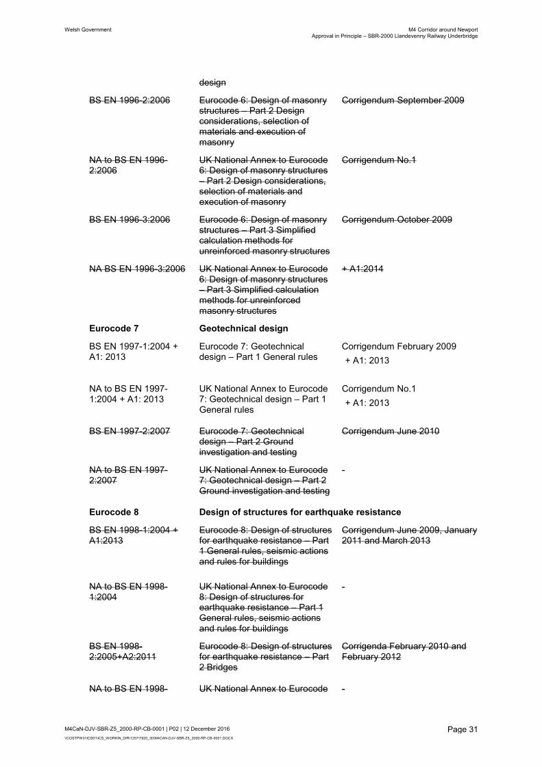
BS EN 1996-2:2006
Eurocode 6: Design of masonry structures – Part 2 Design considerations, selection of materials and execution of masonry
Corrigendum September 2009
NA to BS EN 1996-2:2006
UK National Annex to Eurocode 6: Design of masonry structures – Part 2 Design considerations, selection of materials and execution of masonry
Corrigendum No.1
BS EN 1996-3:2006
Eurocode 6: Design of masonry structures – Part 3 Simplified calculation methods for unreinforced masonry structures
Corrigendum October 2009
NA BS EN 1996-3:2006
UK National Annex to Eurocode 6: Design of masonry structures – Part 3 Simplified calculation methods for unreinforced masonry structures
+ A1:2014
Eurocode 7 Geotechnical design
BS EN 1997-1:2004 + A1: 2013
Eurocode 7: Geotechnical design – Part 1 General rules
Corrigendum February 2009
+ A1: 2013
NA to BS EN 1997-1:2004 + A1: 2013
UK National Annex to Eurocode 7: Geotechnical design – Part 1 General rules
Corrigendum No.1
+ A1: 2013
BS EN 1997-2:2007
Eurocode 7: Geotechnical design – Part 2 Ground investigation and testing
Corrigendum June 2010
NA to BS EN 1997-2:2007
UK National Annex to Eurocode 7: Geotechnical design – Part 2 Ground investigation and testing
-
Eurocode 8 Design of structures for earthquake resistance
BS EN 1998-1:2004 + A1:2013
Eurocode 8: Design of structures for earthquake resistance – Part 1 General rules, seismic actions and rules for buildings
Corrigendum June 2009, January 2011 and March 2013
NA to BS EN 1998-1:2004
UK National Annex to Eurocode 8: Design of structures for earthquake resistance – Part 1 General rules, seismic actions and rules for buildings
-
BS EN 1998-2:2005+A2:2011
Eurocode 8: Design of structures for earthquake resistance – Part 2 Bridges
Corrigenda February 2010 and February 2012
NA to BS EN 1998- UK National Annex to Eurocode -

Welsh Government M4 Corridor around NewportApproval in Principle – SBR-2000 Llandevenny Railway Underbridge
M4CaN-DJV-SBR-Z5_2000-RP-CB-0001 | P02 | 12 December 2016
\\COSTPW01ICS01\ICS_WORKIN_DIR\1257\7920_30\M4CAN-DJV-SBR-Z5_2000-RP-CB-0001.DOCX
Page 32
2:2005 8: Design of structures for earthquake resistance – Part 2 Bridges
BS EN 1998-5:2004
Eurocode 8: Design of structures for earthquake resistance – Part 5 Foundations, retaining structures and geotechnical aspects
-
NA to BS EN 1998-5:2004
UK National Annex to Eurocode 8: Design of structures for earthquake resistance – Part 5 Foundations, retaining structures and geotechnical aspects
-
Eurocode 9 Design of aluminium structures
BS EN 1999-1-1:2007 + A1:2009
Eurocode 9: Design of aluminium structures– Part 1-1 General structural rules
+ A1:2009
NA to BS EN 1999-1-1:2007 + A2:2013
UK National Annex to Eurocode 9: Design of aluminium structures – Part 1-1 General structural rules
+ A2:2013
Corrigendum March 2014
BS EN 1999-1-3:2007 + A1:2011
Eurocode 9: Design of aluminium structures – Part 1-3 Structures susceptible to fatigue
+ A1:2011
NA to BS EN 1999-1-3:2007 + A1:2011
UK National Annex to Eurocode 9: Design of aluminium structures – Part 1-3 Structures susceptible to fatigue
+ A1:2011
BS EN 1999-1-4:2007 +A1:2011
Eurocode 9: Design of aluminium structures – Part 1-4 Cold formed structural sheeting
+ A1:2011
Corrigendum November 2009
NA to BS EN 1999-1-4:2007
UK National Annex to Eurocode 9: Design of aluminium structures – Part 1-4 Cold formed structural sheeting
-
A.2 BSI PUBLISHED DOCUMENT
For guidance only unless clauses are otherwise specified in IAN 124/14(W) Annex B.
PD 6688-1-1:2011 Recommendations for the design of structures to BS EN 1991-1-1
PD 6688-1-4:2009 Background paper to the UK National Annex to BS EN 1991-1-4
PD 6688-1-7:2009 + A1: 2014
Recommendations for the design of structures to BS EN 1991-1-7
PD 6688-2:2011 Recommendations for the design of structures to BS EN 1991-2
PD 6687-1:2010
Background paper to the UK National Annexes to BS EN 1992-1-1 and BS EN 1992-3

Welsh Government M4 Corridor around NewportApproval in Principle – SBR-2000 Llandevenny Railway Underbridge
M4CaN-DJV-SBR-Z5_2000-RP-CB-0001 | P02 | 12 December 2016
\\COSTPW01ICS01\ICS_WORKIN_DIR\1257\7920_30\M4CAN-DJV-SBR-Z5_2000-RP-CB-0001.DOCX
Page 33
PD 6687-2:2008 Recommendations for the design of structures to BS EN 1992-2:2005
PD 6695-1-9:2008 Recommendations for the design of structures to BS EN 1993-1-9
PD 6695-1-10:2009 Recommendations for the design of structures to BS EN 1993-1-10
PD 6695-2:2008 + A1:2012 Incorporating Corrigendum No.1
Recommendation for the design of bridges to BS EN 1993
PD 6696-2:2007 + A1:2012
Background paper to BS EN 1994-2 and the UK National Annex to BS EN 1994-2
PD 6694-1:2011 Recommendations for the design of structures subject to traffic loading to BS EN 1997-1
PD 6698:2009
Recommendations for the design of structures for earthquake resistance to BS EN 1998
PD 6703:2009
Structural bearings – Guidance on the use of structural bearings
PD 6705-2:2010 + A1:2013
Recommendations for the execution of steel bridges to BS EN 1090-2
PD 6705-3:2009 Recommendations on the execution of aluminium structures to BS EN 1090-3
PD 6702-1:2009 Structural use of aluminium. Recommendations for the design of aluminium structures to BS EN 1999
A.3 EXECUTION STANDARDS REFERENCED IN BRITISH STANDARDS OR EUROCODES
BS EN 1090-1:2009+A1:2011
Execution of steel structures and aluminium structures - Part 1: Requirements for conformity assessment of structural components
BS EN 1090-2:2008+A1:2011
Execution of steel structures and aluminium structures – Part 2: Technical requirements for the execution of steel structures
BS EN 1090-3:2008
Execution of steel structures and aluminium structures – Part 3: Technical requirements for aluminium structures
A.4 THE MANUAL CONTRACT DOCUMENT FOR HIGHWAY WORKS (MCHW)
MCHW Volume 1: December 2014 Specification for Highway Works
MCHW Volume 2: December 2014 Notes for guidance on the Specification for Highway Works
MCHW Volume 3: November 2008 Highway Construction Details

Welsh Government M4 Corridor around NewportApproval in Principle – SBR-2000 Llandevenny Railway Underbridge
M4CaN-DJV-SBR-Z5_2000-RP-CB-0001 | P02 | 12 December 2016
\\COSTPW01ICS01\ICS_WORKIN_DIR\1257\7920_30\M4CAN-DJV-SBR-Z5_2000-RP-CB-0001.DOCX
Page 34
A.5 THE DESIGN MANUAL FOR ROADS AND BRIDGES (DMRB)
A.5.1 ADVICE NOTES – BRIDGES AND STRUCTURES (BA SERIES)
BA 26/94 Expansion Joints for Use in Highway Bridge Decks Nov 1994 2.3.7
BA 28/92 Evaluation of Maintenance Costs in Comparing Alternative Designs for Highway Structures
Aug 1992 1.2.2
BA 41/98 The Design and Appearance of Bridges Feb 1998 1.3.11
BA 47/99 Waterproofing and Surfacing of Concrete Bridge Decks Aug 1999 2.3.5
BA 67/96 Enclosure of Bridges Aug 1996 2.2.8
BA 68/97 Crib Retaining Walls Feb 1997 2.1.4
BA 82/00 Formation of Continuity Joints in Bridge Decks Nov 2000 2.3.7
BA 85/04 Coatings for Concrete Highway Structures & Ancillary Structures
May 2004 2.4.3
BA 92/07 Use of recycled concrete aggregates in structural concrete May 2007 2.3.9
A.5.2 BRIDGES AND STRUCTURES, STANDARDS (BD SERIES)
BD 2/12 Technical Approval of Highway Structures May 2012 1.1.1
BD 7/01 Weathering Steel for Highway Structures Nov 2001 2.3.8
BD 10/97 Design of Highway Structures in Areas of Mining Subsidence
May 1997 1.3.14
BD 12/01 Design of Corrugated Steel Buried Structures with Spans Greater than 0.9 metres and up to 8.0 metres
Nov 2001 2.2.6
BD 29/04 Design Criteria for Footbridges Aug 2004 2.2.8
BD 33/94 Expansion Joints for Use in Highway Bridge Decks Nov 1994 2.3.6
BD 35/14 Quality Assurance Scheme for Paints and Similar Protective Coatings
Aug 2014 2.4.1
BD 36/92 Evaluation of Maintenance Costs in Comparing Alternative Designs for Highway Structures
Aug 1992 1.2.1
BD 43/03 The Impregnation of Reinforced and Prestressed Concrete Highway Structures using Hydrophobic Pore-Lining Impregnants
Feb 2003 2.4.2
BD 45/93 Identification Marking of Highway Structures Aug 1993 3.1.1
BD 47/99 Waterproofing and Surfacing of Concrete Bridge Decks Aug 1999 2.3.4
BD 51/14 Portal and Cantilever Sign / Signal Gantries May 2014 2.2.4
BD 62/07 As Built, Operational & Maintenance Records for Highway Structures
Feb 2007 3.2.1
BD 65/14 Design Criteria for Collision Protector Beams Dec 2014 2.2.5
BD 67/96 Enclosures of Bridges Aug 1996 2.2.7
BD 68/97 Crib Retaining Walls Feb 1997 2.1.3
BD 70/03 Strengthened/Reinforced Soils And Other Fills For Retaining Walls And Bridge Abutments
May 2003 2.1.5

Welsh Government M4 Corridor around NewportApproval in Principle – SBR-2000 Llandevenny Railway Underbridge
M4CaN-DJV-SBR-Z5_2000-RP-CB-0001 | P02 | 12 December 2016
\\COSTPW01ICS01\ICS_WORKIN_DIR\1257\7920_30\M4CAN-DJV-SBR-Z5_2000-RP-CB-0001.DOCX
Page 35
BD 78/99 Design of Road Tunnels Aug 1999 2.2.9
BD 82/00 Design of Buried Rigid Pipes Aug 2000 2.2.10
BD 90/05 Design Of FRP Bridges and Highway Structures May 2005 1.3.17
BD 94/07 Design of Minor Structures Feb 2007 2.2.1
A.5.3 BRIDGES, TECHNICAL MEMORANDA (BE SERIES)
A.5.4 TRAFFIC ENGINEERING AND CONTROL, STANDARDS (TD SERIES)
TD 19/06 Requirements for Road Restraint Systems [correction 1 Feb 2008]
Aug 2006 2.2.8
TD 27/05 Cross Sections and Headroom Feb 2005 6.1.2
A.5.5 HIGHWAYS, ADVICE NOTES (HA SERIES)
HA 66/95 Environmental Barriers Technical Requirements Sep 1995 10.5.2
A.5.6 HIGHWAYS, STANDARDS (HD SERIES)
HD 45/09 Road Drainage and the Water Environment Nov 2009 11.3.10
A.6 INTERIM ADVICE NOTES (IAN)
WO1A.1 (IAN 1) TD 37/93 Scheme Assessment Reporting Jan 1996
WO1A.3 (IAN 3) BA 50/93 Post Tensioned Concrete Bridges Apr 1997
WO1A.4 (IAN 4) BD 44/95 The Assessment of Concrete Highway Bridges and Structures
Oct 1996
IAN 41 European Cement Standards Mar 2002
IAN 45 Structures Management Information Systems (SMIS) Phase IV, V and VI Fixing Structures Defects and System Integration
Nov 2002
IAN 47 Post Tensioned Grouted Duct Concrete Bridges Sep 2003
IAN 48 Measures to Minimise the Risk of Sulphate Attack (Including Thaumasite) - New Construction and Structures Under Construction
Sep 2003
IAN 49 Use of Warning Signs for New Asphalt Road Surfaces Apr 2004
IAN 53 Concrete Half-Joint Deck Structures May 2004
IAN 56 Maintenance of Traffic Signs with Dew Resistant Coatings Jan 2005
IAN 64/05 Driver Information Signs at Road Works May 2005
IAN 70/06 (W) Implementation of New Reinforcement Standards (BS 4449:2005, BS 4482:2005, BS 4483:2005 & BS 8666:2005)
Jan 2006
IAN 71 Marker Posts on Lay-By Segregation Islands Sep 2007
IAN 73/06 Design of Pavement Foundations Nov 2009
IAN 83/06 (W) Principal & General Inspection of Sign/Signal Gantries, & Gantries with Low Handrails or Open Mesh Flooring
Aug 2006
IAN 85/07 (W) Design of Passively Safe Portal Signal Gantries Jan 2008
IAN 86/07 (W) Amendments to Design Requirements for Portal & Cantilever Sign/Signal Gantries
Jan 2008

Welsh Government M4 Corridor around NewportApproval in Principle – SBR-2000 Llandevenny Railway Underbridge
M4CaN-DJV-SBR-Z5_2000-RP-CB-0001 | P02 | 12 December 2016
\\COSTPW01ICS01\ICS_WORKIN_DIR\1257\7920_30\M4CAN-DJV-SBR-Z5_2000-RP-CB-0001.DOCX
Page 36
IAN 95/07 (W) Implementation of New Concrete Standards May 2007
IAN 96/07 (W) Guidance on Implementing Results of Research on Bridge Deck Waterproofing
Jul 2007
IAN 97/07 (W) Assessment & Upgrading of Existing Parapets Jan 2009
IAN 105/08 (W) Implementation of Construction (Design Management) Regulations 2007 & The Withdrawal of SD 10/05 & SD11/05
Jan 2008
IAN 110/08 (W) Assessment of Implications (Of Highways Plans & Projects) on European Sites (Including Appropriate Assessment)
Dec 2008
IAN 116/08 (W) Nature Conservation Advice in Relation to Bats Sep 2009
IAN 124/14 (W) Use of Eurocodes for the Design of Highway Structures May 2014
IAN 154/14 (W) Revision of SHW Clause 903, Clause 921 and Clause 942 Aug 2014
IAN 156/14 (W) Revision of Aggregate Specification for Pavement Surfacing Aug 2014
IAN 157/14 (W) Thin Surface Course Systems - Installation and Maintenance Aug 2014
IAN 177/14 (W) Introduction of the Construction Products Regulation (EU) 305_2011
Aug 2014
A.7 RAILWAY SAFETY AND STANDARDS BOARD DOCUMENTS
GC/GN5612 Issue 1 Dec 2014 Guidance on Loading Requirements for the Design of Railway Structures
GC/RT5212 Issue 1 Feb 2003 Requirements for defining and maintaining clearances [plus amendment AM002]
GM/RT2149 Issue 3 Feb 2003 Requirements for defining and maintaining the size of railway vehicles [plus amendments AM001,AM002 and AM003]
GO/RT3413 Issue 1 Aug 2008 Provision of Information and Signs for Access on the Railway [Supersedes GCRT5203 Iss 3]
NR/L3/CIV/020 Issue 1 Jun 2011 Design of Bridges [Replaces RT/CE/S/007 Issue 1]
NR/L3/CIV/140 Various Issues
Various dates
Model clauses for specifying civil engineering work (Various Sections, on different topics)
NR/L3/CIV/151 Issue 6 March 2012
Engineering Assurance of Standard Designs & Details for Building & Civil Engineering Works
NR/GN/CIV/025 Issue 3 Jun 2006 Structural assessment of underbridges
NR/L2/CIV/003 Issue 4 June 2012
Engineering Assurance of Building and Civil Engineering Works
NR/L2/TRK/2049 Issue 12 Mar 2010 Track design handbook
NR/L2/TRK/2102 Issue 6 Mar 2010 Track construction standards

Welsh Government M4 Corridor around NewportApproval in Principle – SBR-2000 Llandevenny Railway Underbridge
M4CaN-DJV-SBR-Z5_2000-RP-CB-0001 | P02 | 12 December 2016
\\COSTPW01ICS01\ICS_WORKIN_DIR\1257\7920_30\M4CAN-DJV-SBR-Z5_2000-RP-CB-0001.DOCX
Page 37
A.8 MISCELLANEOUS
BRE Special Digest 1: 2005:Third Edition Concrete in aggressive ground.
CHE Memorandum 227/08 The Impregnation of Reinforced and Prestressed
Concrete Highway Structures using Hydrophobic Pore
Lining Impregnants
CIRIA C543 Bridge Detailing Guide
CIRIA C580 Embedded Retaining Walls – Guidance for Economic
Design
CIRIA C660 Early-age Thermal Crack Control in Concrete
CIRIA C686 Safe Access for Maintenance and Repair

Welsh Government M4 Corridor around NewportApproval in Principle – SBR-2000 Llandevenny Railway Underbridge
M4CaN-DJV-SBR-Z5_2000-RP-CB-0001 | P02 | 12 December 2016
\\COSTPW01ICS01\ICS_WORKIN_DIR\1257\7920_30\M4CAN-DJV-SBR-Z5_2000-RP-CB-0001.DOCX
Page 38
Appendix B – Drawings

REINFORCED EARTH
WINGWALLS
CA
RRIA
GE
WA
Y
M4 E
AS
TB
OU
ND
PR
OP
OS
ED
CA
RRIA
GE
WA
Y
M4 W
ES
TB
OU
ND
PR
OP
OS
ED
20003
10003
20003
NR BOUNDARY
NR BOUNDARY
NEW NMU ROUTE
NEW NMU ROUTE
UP RELIEF
UP MAIN
DOWN MAIN
DOWN RELIEF
REINFORCED
EARTH
WINGWALLS
REINFORCED EARTH
WINGWALLS
REINFORCED EARTH
WINGWALLS
DIAPHRAGM
DIAPHRAGM
EXISTING SIGNAL
GANTRY
H4a PRECAST
CONCRETE
PARAPET
TRANSITION
BARRIER
TYPE N2W2
SAFETY
BARRIER
TRANSITION
BARRIER
TYPE N2W2
SAFETY
BARRIER
TRANSITION
BARRIER
H4a PRECAST
CONCRETE PARAPET
SSSI
BOUNDARY
BURIED SERVICES
11kV O/H ELEC
11kV U/G ELEC
LV U/G E
LE
C
LV O/H ELEC
b
aN
N: 186968.001m
E: 341608.634m
CHAINAGE: 20050m
HA
RD S
HO
ULD
ER
HA
RD S
HO
ULD
ER
CE
NT
RA
L R
ES
ER
VA
TIO
N
VE
RG
E
VE
RG
E
ABUTMENT
NORTH
ABUTMENT
SOUTH
L
EXISTING SIGNAL
GANTRY
FOUNDATION
EXISTING SIGNAL
GANTRY
FOUNDATION
3-
3-
SYSTEM
HIGHWAY DRAINAGE
DISCHARGE TO CATCH
PIT
CONCRETE
DITCH
450 Ø UPVC PIPE
WITH SLEEVES IN
ABUTMENT WALL TO
ALLOW MOVEMENT
CATCH PIT
CATCH PIT
1200Ø CULVERT
UNDER NMU ROUTE
C
LC
SWITCH BOX SHALL
BE RELOCATED
9415
DISCHARGE
TO SOAKWAY
HAZARD 0619 -
AND LIVE OLE
RAILWAY TRACKS
HAZARD 0632 -
CATCH
PIT
DISCHARGE
TO SOAKWAY
DIS
CH
AR
GE T
O
HIG
HW
AY D
RAIN
AG
E
SYSTE
M
10003
L-SHAPE GROUND BEAM FOR
SUPPORTING GALVANIZED
STEEL H4a PARAPET
L-SHAPE GROUND BEAM FOR
SUPPORTING GALVANIZED
STEEL H4a PARAPET
L-SHAPE GROUND BEAM FOR
SUPPORTING GALVANIZED
STEEL H4a PARAPET TRANSITION OF H4a
CONTAINMENT SAFETY
BARRIER (SEE NOTE 6)
3230
4250
TYPE N2W2
SAFETY
BARRIER
29895
43398
CLE
AR S
PA
N
27055
39429
450
mm.
DI
1978
ABUTMENT
NORTH
ABUTMENT
SOUTH
HAZARD 0619 -
HAZARD 0632 -
FP
P
P
P
P
P
P
P
P
P
P
P
P
P
P
P
P
P
P
P
P
P
P
P
P
P
P
P
P
PP
P
P
PP
PP
PP
PP
PP
PP
PP
450
mm.
DI
1978
COMPACTED FILL
SOIL REINFORCEMENT STRAPS
CONNECTOR
FRONT OF WALL DRAINAGE
CONCRETE STRIP
FOUNDATION
REINFORCED EARTH WALL
PANEL JOINT
STRAINED WIRE FENCE
TO HCD DRAWING H13
PRECAST CONCRETE COPING
M4 CORRIDOR AROUND NEWPORT
SBR-2000
LLANDEVENNY RAILWAY UNDERBRIDGE
GENERAL ARRANGEMENT (SHEET 01 OF 02)
P03
D1
AS SHOWN MWA
05/12/16
BLA
05/12/16
RNW
05/12/16
GRD
06/12/16
P03 MWA BLA RNW06/12/16 Final Issue Incorporating WG commentsM4CaN - DJV - SBR -
Z5_2000 - DR - CB - 0002
Welsh Government comments incorporated
FIRST ISSUE
P02 NR BLA RNW18/03/16
P01 VKR BLA RNW07/08/15
INFORMATION
SAFETY, HEALTH AND ENVIRONMENTAL
(Reference shall also be made to the design hazard log).
detailed on this drawing, note the following significant residual risks
In addition to the hazards/risks normally associated with the types of work
Construction
LIVE OLE.
0632 - CONSTRUCTION ADJACENT TO GREAT WESTERN MAIN LINE RAILWAY AND
0619 - EXCAVATION IN VICINITY OF EXISTING BURIED AND OVERHEAD SERVICES.
Maintenance / Cleaning
0622 - WORKING AT HEIGHT DURING INSPECTION/MAINTENANCE WORK.
UseNone
Decommissioning / Demolition
CONCRETE.
0625 - TEMPORARY INSTABILITY OF ABUTMENT WALLS UNDER LOAD FROM WET
Date
Scale
Drawing Title
Project TitleDrawing Status
DO N
OT S
CA
LE
Date Date DateClient Original Size
Suitability
Millim
etres
100
10
0
A1
Drawing Number Revision
Location Type Role Number
Project Originator Volume
Designed / Drawn Checked Approved Authorised
Rev. Date Description By Chk'd App'd
Project Team
Trwydded yr Arolwg Ordnans 100021874.
© Hawlfraint a hawliau cronfa ddata'r Goron 2015. Rhif
Survey 100021874. Welsh Government.
© Crown Copyright and database right 2015. Ordnance
SCALE 1:2500
LOCATION PLAN
6. FOUNDATION DETAILS TO BE CONFIRMED FOLLOWING A DETAILED REVIEW OF GROUND INVESTIGATION DATA.
5. STRUCTURE IS WITHIN THE SSSI BOUNDARY.
4. SIGNAL GANTRY INFORMATION IS BASED ON DRAWING 5060901/CST/1404 REVISION D01 - AS BUILT DRAWING DATED 26.06.08.
3. ADDITIONAL BURIED SERVICES ARE BASED ON NETWORK RAIL BURIED SERVICES PACK WES106935 DATED JANUARY 2014.
2. ONLY WRITTEN DIMENSIONS SHALL BE USED, DO NOT SCALE.
1. ALL DIMENSIONS ARE IN MILLIMETRES UNLESS NOTED OTHERWISE.
GENERAL NOTES:
SBR-2000
LLANDEVENNY
RAILWAY
UNDERBRIDGE
PR
OP
OS
ED M
4 E
AS
TB
OU
ND
PR
OP
OSE
D M
4 W
ESTB
OU
ND
SOUTH WALES MAIN LINE (SWM2)
STE
EL
WO
RKS A
CC
ESS R
OA
D
SCALE 1:
P1 PLAN- 250
P02
P02
P02
P02
P02
P02
P02
P02
P02
P02
P02
SCALE 1:
3 SECTION- 50
P02P02
P02
P02
P02
P02
P02
P02
FOR COSTING

ABUTMENT
NORTH
ABUTMENT
SOUTH
HAZARD 0619 -
HAZARD 0632 -
FP
P
P
P
P
P
P
P
P
P
P
P
P
P
P
P
P
P
P
P
P
P
P
P
P
P
P
P
P
PP
P
P
PP
PP
PP
PP
PP
PP
PP
450
mm.
DI
1978
CONCRETE BEAMS @1975mm
20No U12 PRESTRESSED
RESERVATION
CENTRAL
11000
CARRIAGEWAY
3300
SHOULDER
HARD
1500
VERGE
11000
CARRIAGEWAY
3300
SHOULDER
HARD
1500
VERGE
G.L
1500
DRAIN
1500
DRAIN
6849
120mm SURFACING
WATERPROOFING
INSITU CONCRETE WALL
CONCRETE
DITCH
2.5%2.5%
RE WING WALLS
TOP OF
WING WALL
PRECAST PARAPET ARE CONNECTED TO
PROTRUDING SHEAR REINFORCEMENT OF
DECK THROUGH IN SITU STITCHING
450 Ø UPVC PIPE WITH
SLEEVE CAST IN
ABUTMENT WALL
RE WING WALLS
TOP OF
WING WALL
CONCRETE
DITCH
CONCRETE
DITCH
TEMPORARY INSTABILITY
HAZARD 0625 -
STRAINED WIRE FENCE
TO HCD DRAWING H13
STRAINED WIRE
FENCE
POLYURETHANE JOINT SEALANT BETWEEN
RE WALL AND ABUTMENT WALL
POLYURETHANE JOINT SEALANT BETWEEN
RE WALL AND ABUTMENT WALL
1850
1850
1975
DOWN
MAIN
DOWN
RELIEF
UP
RELIEFUP
MAIN
8.631m8.391m8.509m8.631m
200
6425
4500
NMU ROUTE
35752700
4500
ZONE
FENCE
150
4.78m CLEARANCE
5.45m CLEARANCE
8317
1603
FOR DETAILS OF CONTAINMENT
BARRIER ARRANGEMENT REFER
TO 'TATA' TRANSITION DRAWING REFER:
P365/T/149 OR SIMILAR APPROVED
CONCRETE
ABUTMENT WALL
2m HIGH
PALISADE
FENCE
1050Ø BORED
PILES @ 1200 CTS
DIAPHRAGM
28405
DIAPHRAGM
1350
ABUTMENT
NORTH
ABUTMENT
SOUTH
C
1500
1500
27055 CLEAR SPAN
POLYURETHANE JOINT SEALANT
BETWEEN RE WALL AND ABUTMENT WALL
POLYURETHANE JOINT SEALANT
BETWEEN RE WALL AND ABUTMENT WALL
6N/6P
STRUCTURAL FILL
BEHIND ABUTMENT
STRAINED WIRE FENCE
TO HCD DRAWING H13STRAINED WIRE FENCE
TO HCD DRAWING H13
6N/6P
STRUCTURAL FILL
BEHIND ABUTMENT
1500
L CL
4500
1500
BLIDDING
MIN.
500
L - SHAPE R.C.
GROUND BEAM
WORKING AT HEIGHT
HAZARD 0622 -
AND LIVE OLE
RAILWAY TRACKS
HAZARD 0632 -
PROPOSED OLE TO BE
FIXED UNDER THE BRIDGE
PRECAST H4a VERY HIGH
CONTAINMENT PARAPET
M4 CORRIDOR AROUND NEWPORT
SBR-2000
LLANDEVENNY RAILWAY UNDERBRIDGE
GENERAL ARRANGEMENT (SHEET 02 OF 02)
P02
D1
AS SHOWN MWA
05/12/16
BLA
05/12/16
RNW
05/12/16
GRD
06/12/16
P02 MWA BLA RNW06/12/16 Final Issue Incorporating WG commentsM4CaN - DJV - SBR -
Z5_2000 - DR - CB - 0003
Welsh Government comments incorporated
P01 LV BLA RNW18/03/16
Date
Scale
Drawing Title
Project TitleDrawing Status
DO N
OT S
CA
LE
Date Date DateClient Original Size
Suitability
Millim
etres
100
10
0
A1
Drawing Number Revision
Location Type Role Number
Project Originator Volume
Designed / Drawn Checked Approved Authorised
Rev. Date Description By Chk'd App'd
Project Team
Trwydded yr Arolwg Ordnans 100021874.
© Hawlfraint a hawliau cronfa ddata'r Goron 2015. Rhif
Survey 100021874. Welsh Government.
© Crown Copyright and database right 2015. Ordnance
SCALE 1:2500
LOCATION PLAN
6. FOUNDATION DETAILS TO BE CONFIRMED FOLLOWING A DETAILED REVIEW OF GROUND INVESTIGATION DATA.
5. STRUCTURE IS WITHIN THE SSSI BOUNDARY.
4. SIGNAL GANTRY INFORMATION IS BASED ON DRAWING 5060901/CST/1404 REVISION D01 - AS BUILT DRAWING DATED 26.06.08.
3. ADDITIONAL BURIED SERVICES ARE BASED ON NETWORK RAIL BURIED SERVICES PACK WES106935 DATED JANUARY 2014.
2. ONLY WRITTEN DIMENSIONS SHALL BE USED, DO NOT SCALE.
1. ALL DIMENSIONS ARE IN MILLIMETRES UNLESS NOTED OTHERWISE.
GENERAL NOTES:
SBR-2000
LLANDEVENNY
RAILWAY
UNDERBRIDGE
PR
OP
OS
ED M
4 E
AS
TB
OU
ND
PR
OP
OSE
D M
4 W
ESTB
OU
ND
SOUTH WALES MAIN LINE (SWM2)
STE
EL
WO
RKS A
CC
ESS R
OA
D
SCALE 1:
1 SECTION0002 100
SCALE 1:
2 SECTION0002 100
INFORMATION
SAFETY, HEALTH AND ENVIRONMENTAL
(Reference shall also be made to the design hazard log).
detailed on this drawing, note the following significant residual risks
In addition to the hazards/risks normally associated with the types of work
Construction
LIVE OLE.
0632 - CONSTRUCTION ADJACENT TO GREAT WESTERN MAIN LINE RAILWAY AND
0619 - EXCAVATION IN VICINITY OF EXISTING BURIED AND OVERHEAD SERVICES.
Maintenance / Cleaning
0622 - WORKING AT HEIGHT DURING INSPECTION/MAINTENANCE WORK.
UseNone
Decommissioning / Demolition
CONCRETE.
0625 - TEMPORARY INSTABILITY OF ABUTMENT WALLS UNDER LOAD FROM WET
P01
P01
P01
P01
P01
P01
P01
P01
P01
P01
P01
P01
P01
FOR COSTING

Welsh Government M4 Corridor around NewportApproval in Principle – SBR-2000 Llandevenny Railway Underbridge
M4CaN-DJV-SBR-Z5_2000-RP-CB-0001 | P02 | 12 December 2016
\\COSTPW01ICS01\ICS_WORKIN_DIR\1257\7920_30\M4CAN-DJV-SBR-Z5_2000-RP-CB-0001.DOCX
Page 39
Appendix C – Form C Geotechnical Summary Sheet CHAINAGE
INTERVAL:
20+020 TYPE: Railway Underbridge REFERENCES
/COMMENTS
AIP REF
No:
M4CaN-DJV-SBR-
Z5_2000-RP-CB-0001
DESIG
N LIFE:
120 years
RELEVANT EXPLORATORY HOLES
1998 – Norwest Holst – BHM6
2008 – Norwest Holst – SBHM02 CP, SBHM02 RC
2015 – Geotechnical Engineering Ltd. – BH538, BH539, BH540, BH541
Full references are contained
within the GDR.
LOCATION-SPECIFIC GROUND PROFILE
Northern Abutment
STRATA DEPTH TO
BASE* (mOD)
STRATA DESCRIPTION
Head Deposits 10.0
Slightly gravelly sand with cobbles Existing ground level is approx.
11.0m AOD
Attached to the Form C is an
indicative exploratory hole
location plan and schematic
geological long section.
The plan, section and ground
profile are based on all the
ground investigation data.
Tintern Sandstone Formation Not Proven Weak to moderately strong medium to
coarse sandstone
Southern Abutment
Estuarine Alluvium 2.5 Very soft, soft and firm silty sandy clay Existing ground level is approx.
6.50m AOD
Attached to the Form C is an
indicative exploratory hole
location plan and schematic
geological long section.
The plan, section and ground
profile are based on all the
ground investigation data.
Weathered Tintern Sandstone
Formation
1.0 Slightly gravelly sand.
Tintern Sandstone Formation Not Proven Weak to moderately strong medium to
coarse sandstone.
PREVIOUS GROUND
HISTORY
The railway line has been present at this site since 1882 ether
side has remained open land in the form of fields.
The potentially contaminated land
sites (CL) and impact on the
structure foundations are to be
addressed in the main GDR text
CONTAMINATION
RISK ASSESSMENT
Potentially contaminated land site CL-29 located at the
bridge. It is not anticipated that remediation of the made
ground will be required but this is pending further
investigation.
A full risk assessment will be
carried out as part of the
Environmental Statement.

Welsh Government M4 Corridor around NewportApproval in Principle – SBR-2000 Llandevenny Railway Underbridge
M4CaN-DJV-SBR-Z5_2000-RP-CB-0001 | P02 | 12 December 2016
\\COSTPW01ICS01\ICS_WORKIN_DIR\1257\7920_30\M4CAN-DJV-SBR-Z5_2000-RP-CB-0001.DOCX
Page 40
GROUNDWATER
Groundwater was encountered at 1m below ground level in
BH539.
Groundwater monitoring conducted in BH539 recorded
groundwater level of 0.56m below ground level in an installation within the Tintern Sandstone Formation.
Groundwater monitoring conducted in BH541 recorded groundwater level of 6.67 m below ground level in an
installation within the Tintern Sandstone Formation
Geotechnical Engineering Ltd.
(2015)
Full references are contained
within the GIR.
SPREAD FOUNDATION DESIGN
STRUCTURE
ELEMENT
BASE
(mAOD)
FOUNDING
STRATUM
FOOTING
SIZE (m)
‘ALLOWABLE’
BEARING PRESSURE
(kN/m2)
Northern
Abutment
TBD Weathered
sandstone
TBD TBD
PILE DESIGN
PILE TYPE: Bored (cased) or CFA Piled foundations will be required due
to the thickness of soft soils
underlying the southern abutment
*Based on DA1-C2
CRITERIA FOR TOE: *4.7m rock socket into Mercia Mudstone
NEG. SKIN FRICTION: In soft Alluvium/Peat 225 kN
STRUCTURE
ELEMENT
TOE
(mAOD)
FOUNDING
STRATUM
LENGTH
(m)
DIAMETER
(m)
*WORKING
(kN)
Southern
Abutment
-3.5 Tintern Sandstone 10 0.9 1245
SETTLEMENT
STRUCTURE
ELEMENT
BASE
(mAOD)
IMMED’T
E (mm)
TOTAL
(mm)
90%
(Months)
REMAINING
(mm)
.
Northern
Abutment
TBD TBD TBD TBD TBD
Southern
Abutment
-3.5 <10mm <10mm <10mm <10mm
DIFFERENTIAL across the structure (mm): 10mm
CHEMICAL ANALYSIS
SPECIES 2:1 EXTRACT SOIL WATER OTHER Geotechnical Engineering Ltd. (2015)
Full references are contained within
the GIR. SO4
-/S2-/S: 0.021 -
CHLORIDE: -
pH: 7.9
Mg: -
REDOX: -
BRE SD1 CLASSES (DS/ACEC/DC): To be determined during the detailed design
OTHER DESIGN FEATURES (e.g. foundation treatment/hazards)

Welsh Government M4 Corridor around NewportApproval in Principle – SBR-2000 Llandevenny Railway Underbridge
M4CaN-DJV-SBR-Z5_2000-RP-CB-0001 | P02 | 12 December 2016
\\COSTPW01ICS01\ICS_WORKIN_DIR\1257\7920_30\M4CAN-DJV-SBR-Z5_2000-RP-CB-0001.DOCX
Page 41
Reinforced earth walls are to be used to the rear of the wing walls. It is likely that monitoring of the
railway will be required as part of the works due to the bored pile and potential driven pile installation.
NOTES

Welsh Government M4 Corridor around NewportApproval in Principle – SBR-2000 Llandevenny Railway Underbridge
M4CaN-DJV-SBR-Z5_2000-RP-CB-0001 | P02 | 12 December 2016
\\COSTPW01ICS01\ICS_WORKIN_DIR\1257\7920_30\M4CAN-DJV-SBR-Z5_2000-RP-CB-0001.DOCX
Page 42
Appendix D - CDM Hazard Log
Ref No.
Hazard Designer measures taken and considered to eliminate or reduce risk
Residual risk information to pass onto Contractor
0613 Falls from deck edge
Integral construction simplifies working at height. Abutments and wingwalls could be designed to allow for backfill to bottom of beam level, prior to placing the beams, to reduce the risk of working at height. Precast concrete deck edge beams are used where possible to reduce the amount of edge working at height.
The residual hazards carry standard construction risks that have been reduced to an acceptable level for an experienced contractor to manage.
0614 Crane collapse during lifting operations
The weight and position of the centroid of gravity of elements to be provided on relevant drawings.
The residual hazards carry standard construction risks that have been reduced to an acceptable level for an experienced contractor to manage.
0615 Painting of steel parapets at height and adjacent to live traffic
Design to adopt galvanised steel parapets to negate need for painting.
The residual hazards carry standard construction risks that have been reduced to an acceptable level for an experienced contractor to manage.
0616 Temporary stability during backfill to abutments / wingwalls / reinforced earth walls. Lateral earth pressure leading to abutment / wingwall / reinforced earth wall collapse
Backfill to the retaining walls only to be carried out once the bridge deck is constructed and the deck / retaining walls integral connections are made. Construction sequence to be detailed on the design drawings. Reinforced earth panels to be adequately supported during backfilling.
Limitation on backfill height before deck construction.
0617 Collapse of excavation causing work force to be buried, crushed or trapped in excavation
Excavations to be kept to a minimum depth by design, temporary works to be designed for stability. Maximum excavation slopes to be provided for stability.
The residual hazards carry standard construction risks that have been reduced to an acceptable level for an experienced contractor to manage.

Welsh Government M4 Corridor around NewportApproval in Principle – SBR-2000 Llandevenny Railway Underbridge
M4CaN-DJV-SBR-Z5_2000-RP-CB-0001 | P02 | 12 December 2016
\\COSTPW01ICS01\ICS_WORKIN_DIR\1257\7920_30\M4CAN-DJV-SBR-Z5_2000-RP-CB-0001.DOCX
Page 43
0618 Risk of ground conditions varying from those assumed in design leading to settlement / damage to structure
Proposed geotechnical investigation to confirm assumptions.
The residual hazards carry standard construction risks that have been reduced to an acceptable level for an experienced contractor to manage.
0619 Excavation in vicinity of existing buried and overhead services
Full consultation undertaken with utility companies prior to commencement on site. Contractor to undertake own service enquiries and to clearly, mark, protect or divert. CAT scans to be undertaken prior to any excavations.
Nearly underground cables shown on drawings
0620 Working adjacent to live traffic
M4CaN will be constructed away from the existing M4. Structures affecting local traffic will require traffic management during construction.
The residual hazards carry standard construction risks that have been reduced to an acceptable level for an experienced contractor to manage.
0621 Bridge deck props abutments - removal may cause instability of abutments
Risk to be noted on bridge drawings.
Note required for demolition stage on drawing
0622 Working at height during inspection / maintenance work
Use of MEWPs for inspection. Lane closures required to segregate workforce from moving traffic.
The residual hazards carry standard construction risks that have been reduced to an acceptable level for an experienced contractor to manage.
0623 Working at height leading to falls from height and material falling on to workforce below
Integral construction simplifies working at height. Appropriate construction sequence to be state in the structures design statement and on drawings. Abutments and wingwalls could be designed to allow for backfill to bottom of beam level, prior to placing the beams, to reduce the risk of working at height.
The residual hazards carry standard construction risks that have been reduced to an acceptable level for an experienced contractor to manage.
0624 Flooding of excavation prior to installation of permanent drainage
Reduce depth of foundations as much as possible. Advise Contractor of risk of ground water so that they can manage the risk to the temporary works. Hazard to be highlighted on construction drawings where necessary.
The residual hazards carry standard construction risks that have been reduced to an acceptable level for an experienced contractor to manage.
0625 Temporary instability of abutment walls under load from wet concrete
Temporary works shall be designed to accommodate any foreseeable instability
The residual hazards carry standard construction risks that have been reduced to an acceptable level for an experienced contractor to manage.

Welsh Government M4 Corridor around NewportApproval in Principle – SBR-2000 Llandevenny Railway Underbridge
M4CaN-DJV-SBR-Z5_2000-RP-CB-0001 | P02 | 12 December 2016
\\COSTPW01ICS01\ICS_WORKIN_DIR\1257\7920_30\M4CAN-DJV-SBR-Z5_2000-RP-CB-0001.DOCX
Page 44
0626 Risk of unexploded ordnance in region of bridge foundations and embankments
Preliminary Risk Assessment by Bactec - report No. 5750TA 21/11/2014, supplied to M4CaN project team. Further onsite investigation proposed in medium / high risk areas.
The residual hazards carry standard construction risks that have been reduced to an acceptable level for an experienced contractor to manage.
0627 Repetitive manual handling of heavy reinforcement during steel fixing operations causing harm to workforce.
Reinforcement to be detailed to avoid excessively heavy bars where practicable. Large diameter bar lengths to be reduced where possible.
The residual hazards carry standard construction risks that have been reduced to an acceptable level for an experienced contractor to manage.
0628 Concurrent site activities
Hazard cannot be eliminated at the design stage. To be controlled through site procedures.
The residual hazards carry standard construction risks that have been reduced to an acceptable level for an experienced contractor to manage.
0629 Demolition of precast beams causing snapping of prestressed tendons
Beams to be broken out and lifted out rather than demolishing beams. This is to prevent prestressed strands from releasing during demolition. Demolition sequence to be reverse of construction sequence.
The residual hazards carry standard construction risks that have been reduced to an acceptable level for an experienced contractor to manage
0630 Temporary stability of precast beams under weight of wet concrete, leading to collapse
Temporary works shall be designed to accommodate any foreseeable instability
The residual hazards carry standard construction risks that have been reduced to an acceptable level for an experienced contractor to manage.
0631 Errors in the fabrication and precasting of beams leading to substandard structure
Precast elements to be inspected prior to casting of deck. Final survey of precast concrete works to be undertaken prior to delivery to site.
The residual hazards carry standard construction risks that have been reduced to an acceptable level for an experienced contractor to manage.
0632 Construction adjacent to Great Western Main Line railway and live OLE
Precast beams proposed to aid speed of construction with minimal risk of fouling railway tracks.
The Contractor need to liaise with Network Rail regarding possession and isolation of live OLE during critical construction activities.
0633 Risk of reinforced earth wall collapse
Reinforced earth wall panels will require stabilisation when fill is removed
The residual hazards carry standard construction risks that have been reduced to an acceptable level for an experienced contractor to manage.

Welsh Government M4 Corridor around NewportApproval in Principle – SBR-2000 Llandevenny Railway Underbridge
M4CaN-DJV-SBR-Z5_2000-RP-CB-0001 | P02 | 12 December 2016
\\COSTPW01ICS01\ICS_WORKIN_DIR\1257\7920_30\M4CAN-DJV-SBR-Z5_2000-RP-CB-0001.DOCX
Page 45
0634 Damage to existing Network Rail services
Full consultation to be undertaken with Network Rail prior to commencement on site. Contractor to undertaken own service enquiries and to clearly mark, protect or divert. Safe method of working adjacent to and above Network Rail infrastructure to be agreed with Network Rail.
The residual hazards carry standard construction risks that have been reduced to an acceptable level for an experienced contractor to manage.

Welsh Government M4 Corridor around NewportApproval in Principle – SBR-2000 Llandevenny Railway Underbridge
M4CaN-DJV-SBR-Z5_2000-RP-CB-0001 | P02 | 12 December 2016
\\COSTPW01ICS01\ICS_WORKIN_DIR\1257\7920_30\M4CAN-DJV-SBR-Z5_2000-RP-CB-0001.DOCX
Page 46
Appendix E – Idealised Structure Diagrams
Figure 1: Idealised Structure – Isometric View
Extract from BS 8006-1:2010: Section 6 Walls and Abutments

Welsh Government M4 Corridor around NewportApproval in Principle – SBR-2000 Llandevenny Railway Underbridge
M4CaN-DJV-SBR-Z5_2000-RP-CB-0001 | P02 | 12 December 2016
\\COSTPW01ICS01\ICS_WORKIN_DIR\1257\7920_30\M4CAN-DJV-SBR-Z5_2000-RP-CB-0001.DOCX
Page 47

Welsh Government M4 Corridor around NewportApproval in Principle – SBR-2000 Llandevenny Railway Underbridge
M4CaN-DJV-SBR-Z5_2000-RP-CB-0001 | P02 | 12 December 2016
\\COSTPW01ICS01\ICS_WORKIN_DIR\1257\7920_30\M4CAN-DJV-SBR-Z5_2000-RP-CB-0001.DOCX
Page 48
Appendix F – Schedule of Eurocode Options and Choices
To be included at KS6.