m600 oem module installation notes - lumasenseinc.com · m600 installation notes page 1 of 4...
TRANSCRIPT

LUXTRON m600 OEM Module
m600 Installation Notes Page 1 of 4 5/19/16
m600 OEM Module Installation NotesOverviewThis technical note addresses common concerns when installing the m600- OEM (or -OEM Utility) fiberoptic temperature modules. These modules require proper care with regards to power, grounding andshielding to operate at peak performance. Connectors, pins, power supply and shielding covers are allsupplied as separate items, and require the user to install separately.
Additional SupportLumaSense Technologies, Inc.North America - Santa Clara, CA
Phone: +1 800 631 0176 or +1 408 727 1600Fax: +1 408 727 1677
Email: [email protected]
System Componentsm600 OEM Module (for standard LumaSense FOT probes)
Part Number Description00-13144-02 m602: 2 channels, 5 VDC power input, 0-10 V analog output00-13144-04 m604: 4 channels, 5 VDC power input, 0-10 V analog output00-13564-02 m602: 2 channels, 24 VDC power input, 0-10 V analog output00-13564-04 m604: 4 channels, 24 VDC power input, 0-10 V analog output00-14139-02 m602: 2 channels, 24 VDC power input, 4-20 mA analog output00-14139-04 m604: 4 channels, 24 VDC power input, 4-20 mA analog output
m600 OEM Utility Module (for DipTip or Quality probes)
Part Number Description00-14976-21 1 channel, 24 VDC power supply input, 0 ... 1 mA output00-14976-22 2 channels, 24 VDC power supply input, 0 ... 1 mA output00-14976-24 4 channels, 24 VDC power supply input, 0 ... 1 mA output00-14975-21 1 channel, 24 VDC power supply input, 4 ... 20 mA output00-14975-22 2 channel, 24 VDC power supply input, 4 ... 20 mA output00-14975-24 4 channel, 24 VDC power supply input, 4 ... 20 mA output00-14003-21 1 channel, 24 VDC power supply input, 0 ... 10 VDC output00-14003-22 2 channel, 24 VDC power supply input, 0 ... 10 VDC output00-14003-24 4 channel, 24 VDC power supply input, 0 ... 10 VDC output** 5VDC power supply versions are also available

LUXTRON m600 OEM Module
m600 Installation Notes Page 2 of 4 5/19/16
AccessoriesThe following accessories are needed to fully configure the m600 OEM system:
Picture Description LumaSense Part NumberMating connector for powerinput and RS232 connections.Manufactured by PhoenixContact (MVSTBW 2,5/9-st-5,08).
47-1060-08
Mating connector for analogoutput. Manufactured byPhoenix Contact (MCC-1/8-STZF-3,81).
47-1163
Contact pins for analog output.Manufactured by PhoenixContact (MCC-MT 0,5-1,0).
47-1162
DIN rail segment pre-cut to45 mm length for use inmounting an m600 OEM UtilityModule.
90-2176
Metal EMI Shield for M60X units 04-13849-02 (2 channels)04-13849-04 (4 channels)
LUXTRON m600 OEM Module
m600 Installation Notes Page 3 of 4 5/19/16
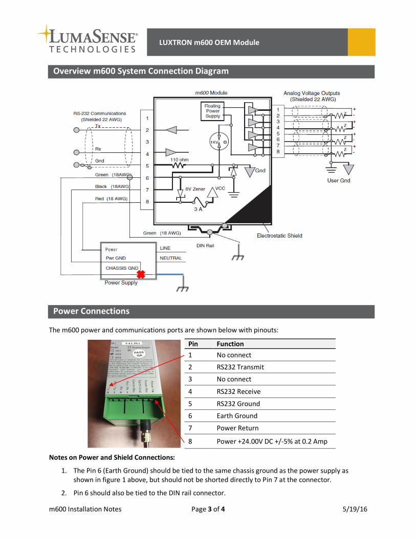
Overview m600 System Connection Diagram
Power Connections
The m600 power and communications ports are shown below with pinouts:
Pin Function1 No connect
2 RS232 Transmit
3 No connect
4 RS232 Receive
5 RS232 Ground
6 Earth Ground
7 Power Return
8 Power +24.00V DC +/-5% at 0.2 Amp
Notes on Power and Shield Connections:
1. The Pin 6 (Earth Ground) should be tied to the same chassis ground as the power supply asshown in figure 1 above, but should not be shorted directly to Pin 7 at the connector.
2. Pin 6 should also be tied to the DIN rail connector.

LUXTRON m600 OEM Module
m600 Installation Notes Page 4 of 4 5/19/16
3. An electrostatic shield (PN: 04-13849-02) should be placed around the m600. The Pin 6 shouldbe attached to this shield via the post on the shield side.
4. The power supply ground should not be tied to Earth Ground (see red X in figure above). Thepower supply should be floating.
5. The RS-232 communication ground (Comm Rtn) and should be connected to Pin5 and this shouldnot be connected to the Power ground, or Earth ground
Analog Output Connections
The m600 analog ports are shown below with pinouts:
Pin Function1 Analog Output Channel 4
2 Analog Ground
3 Analog Output Channel 3
4 Analog Ground
5 Analog Output Channel 2
6 Analog Ground
7 Analog Output Channel 1
8 Analog Ground
The connector and conductor pins are purchased separately (See parts list above)
The m600 connections diagram shows how to wire the analog connectors. More details can be found inthe user manual.
Notes on Analog connections:
1. All grounds 2, 4, 6, 8 are common and a single wire can be used if needed2. The shield around the conductors must be connected only at one end. (Shown in the figure
connected at the customer’s Analog input connector)3. We recommend twisted pair, 2-wire conductors, with a single shield conductor, but multiple
shields can be used as shown in the figure.