m772 concrete bridge repairs – investigation · m772: concrete bridge repairs – investigation ....
TRANSCRIPT
ROADS AND MARITIME SERVICES (RMS)
QA SPECIFICATION M772
CONCRETE BRIDGE REPAIRS – INVESTIGATION
NOTICE
This document is a Roads and Maritime Services QA Specification. It has been developed for use with roadworks and bridgeworks contracts let by Roads and Maritime Services or by local councils in NSW. It is not suitable for any other purpose and must not be used for any other purpose or in any other context.
Copyright in this document belongs to Roads and Maritime Services.
REVISION REGISTER
Ed/Rev Number
Clause Number Description of Revision Authorised
By Date
Ed 1/Rev 0 First edition GM, IC 19.11.12
Edition 1 / Revision 0 ROADS AND MARITIME SERVICES November 2012

GUIDE NOTES (Not Part of Contract Document)
These guide notes provide guidance to RMS personnel on the application of the Specification and preparation of the project-specific annexures. They do not form part of the Specification or of the Contract [or Agreement].
USING M772
M772 has been developed specifically for use under RMS internal Alliance arrangements or Single Invitation Maintenance Contracts for concrete investigation work on existing bridges that are the responsibility of the RMS, using RMS ‘contract’ personnel, consultants and other external specialist personnel. It should not be used for any other type of contract without a full review of its suitability for that application.
M772 is a QA specification and the use of QA specifications requires the implementation of a quality system by the Contractor that meets the quality system requirements specified in RMS Q.
EDITION 1
This is the first issue of the Specification. Suggestions for improvement and amendments on technical issues following use of the Specification in the field should be directed to the Supervising Bridge Engineer (Rehabilitation Design), Bridge & Structural Engineering. Any other comments or suggestions should be forwarded to the Manager, Contracts Quality, Infrastructure Contracts Branch.
OUTLINE OF M772 Specifications for concrete bridge repairs
Existing concrete bridge repairs are covered by three RMS Maintenance Specifications and one RMS guidelines document as follows:
M772: Concrete Bridge Repairs – Investigation
M773: Concrete Bridge Repairs – Design
M769: Concrete Bridge Repairs – Construction
RMS Concrete Bridge Repairs – Guidelines
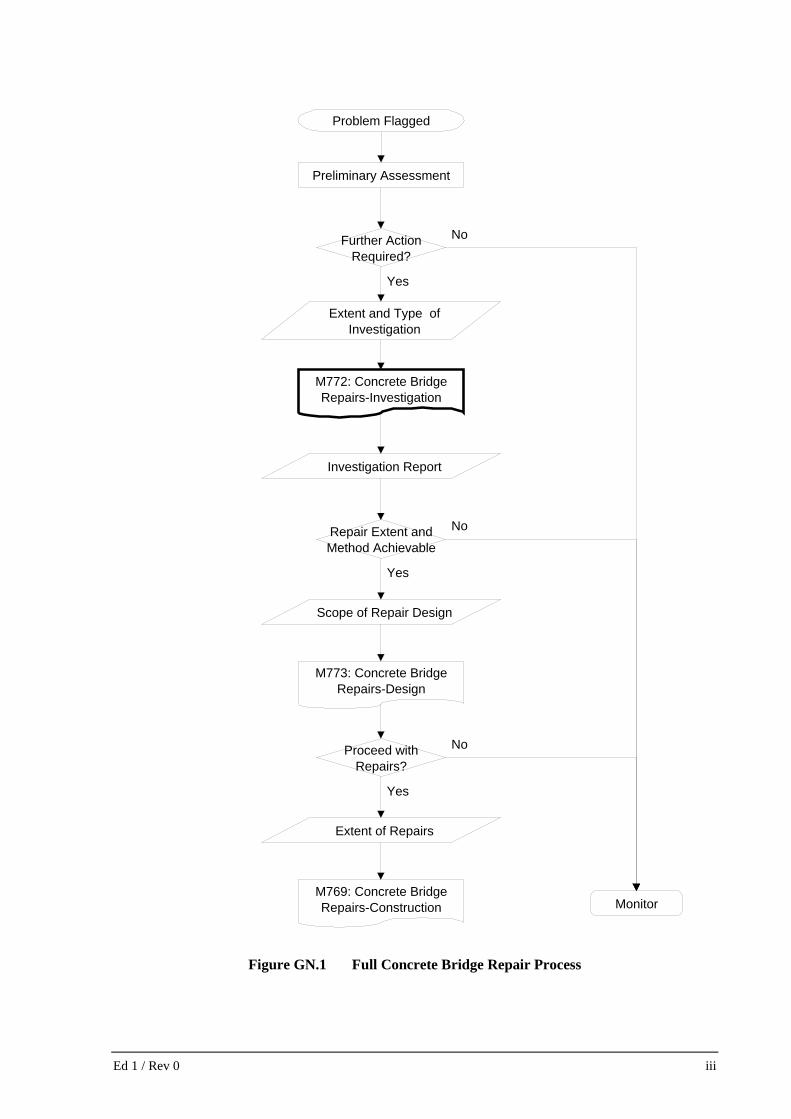
M772 covers the detailed investigation required for the assessment of defective (damaged or deteriorated) concrete bridge members, with a view to their subsequent repair. It constitutes the first of three specifications covering the repair process. The flowchart in Fig. GN.1 outlines the full repair process and the links between the three specifications.
Preliminary assessment by the Principal
The Principal (normally the Bridge Maintenance Planner) must initiate the repair process by organising and carrying out a preliminary assessment and then, based on its outcome, deciding on the actions required, as shown in the flowchart in Fig. GN.1.
Where there is an immediate need to open the bridge to traffic or to restore structural integrity as part of an emergency response to impact damage, the Principal should organise this before calling up Work under this Specification, which DOES NOT cover such emergency response.
Main activities to be executed under M772
Desktop review.
Edition 1 / Revision 0 ROADS AND MARITIME SERVICES November 2012
Field assessment: - Visual inspection; - Delamination survey; and - Diagnostic testing.
Provision of investigation report: - Extent and location of defects; - Causes, diagnosis; and - Repair options/methods.
SECTION 1 GENERAL Scope
This Specification covers investigation work for the repair of all defective concrete bridge members except those which are:
(a) located permanently underwater; (b) buried in the ground; or (c) fire damaged. Work required as part of an emergency response to stabilise the bridge immediately after impact damage is not covered by this Specification. Details of Work
ANNEXURE A must be completed by the Principal after carrying out a preliminary assessment of the damaged bridge.
ANNEXURE M772/A1 covers general bridge information, location and extent of investigation and constraints that may impact on repair options such as allocated budget and time constraints, etc.
The Principal must nominate the members to be investigated, percentage of areas to be covered and number of diagnostic testing areas (DTA) on each member. Enter the required number and types of diagnostic tests for each DTA in ANNEXURE M772/A2.
Details of tests, number of samples required and test method are specified in ANNEXURE M772/A3.
Enter the information to be supplied by the Principal in ANNEXURE M772/A4.
SECTION 2 PLANNING PROJECT QUALITY PLAN
The PROJECT QUALITY PLAN (PQP) is critical to this Specification. The PQP should be prepared before the Work commences, and must be based on RMS Guidelines, RMS Manuals and other appropriate information.
The PQP must be used by the Contractor at all times during the Work. Amendments are to be kept up to date by the Contractor and periodically resubmitted to the Principal.
ii Ed 1 / Rev 0
Extent and Type of Investigation
Further Action Required?
Preliminary Assessment
Problem Flagged
M772: Concrete Bridge Repairs-Investigation
Investigation Report
Extent of Repairs
M769: Concrete Bridge Repairs-Construction
Scope of Repair Design
Monitor
No
Repair Extent and Method Achievable
No
Yes
Yes
M773: Concrete Bridge Repairs-Design
Proceed with Repairs?
Yes
No
Figure GN.1 Full Concrete Bridge Repair Process
Ed 1 / Rev 0 iii
The Principal must carry out regular surveillance of the Work using experienced officers.
The PQP must address the type of investigation nominated, including investigation procedures, and associated testing and sampling equipment and techniques.
Other Plans
Depending on the type of investigation and the location of, and access to, defects a TRAFFIC CONTROL PLAN may be required.
Documents
The Principal should provide the Contractor with all the available information on the bridge listed in ANNEXURE A.4. Principal-supplied information includes drawings and reports. Reports may include the preliminary investigation report, Bridge Information System condition and inspection reports, structural assessment reports, repair records etc. Drawings may include the ORIGINAL DRAWINGS and WORK-AS-EXECUTED DRAWINGS, etc.
The Contract Manager must collate all the relevant information for the contract and supply it to the Contractor. Ensure that irrelevant or out of date documents are not provided to the Contractor.
Note that ORIGINAL DRAWINGS for most bridges are available electronically from RMS PLANS MANAGER.
SECTION 3 RESOURCES Personnel
Experienced and qualified personnel are required to supervise and carry out the desk top analysis of relevant documents, and the field assessment and evaluation of current condition of concrete members.
Refer names of consultants and structural engineers proposed by the Contractor to Bridge & Structural Engineering for review.
Surveyors may be required to verify the location and levels of concrete members to assist in the measurements of settlements and misalignment.
The following personnel must be nominated in the PQP and their suitability should be reviewed by the Principal:
- Consultants, where required;
- Bridge Inspectors;
- Project Engineer (the Project Manager);
- Site Supervisor (Works Supervisor);
- Scaffolder and Rigger, where required.
Plant and equipment
All items of equipment used for inspection, testing, sampling and/or measurements must be used within their specified working range.
iv Ed 1 / Rev 0
SECTION 4 EXECUTION Investigation
The Principal must nominate the type of investigation in ANNEXURE M772/A1 as a BASIC INVESTIGATION or a COMPLEX INVESTIGATION.
A BASIC INVESTIGATION is recommended where:
- The exact nature and causes of defects are readily identifiable;
- Defects have limited extent and effects on the bridge; and
- Members to be repaired and/or extent of repairs have already been predetermined.
Otherwise, carry out a COMPLEX INVESTIGATION.
The Contractor must carry out a desktop review appropriate to the nominated investigation type before the field assessment. The Principal-supplied information is the main resource for this review.
Based on the outcome of the preliminary investigation, the Principal must nominate the bridge members to be investigated and the extent to be covered on each by visual inspection, delamination survey and diagnostic testing, as detailed in ANNEXURES M772/A1, A2 & A3.
Field Assessment
Defects include all visible or hidden deterioration and/or damage in concrete bridge members resulting from design errors, construction faults, applied loads or environmental conditions, together with contributing mechanical, physical or chemical factors.
Visible defects include:
(a) construction faults - such as blow holes, honeycombing, cold joints, exposed reinforcement, irregular surfaces and misalignment;
(b) discolouration - such as efflorescence, dampness, and rust stains; (c) rupture of the concrete - such as cracking, disintegration, spalling, and delamination; (d) displacement of the concrete member.
Diagnostic testing/sampling used in the field assessment must be in accordance with ANNEXURE A.3. Diagnostic testing/sampling must be planned and designed to limit damage to the bridge from the testing to a minimum. Consider firstly the use of non-destructive techniques for testing and/or inspection before allowing destructive testing or inspection.
Before core drilling prestressed concrete members, physically locate and mark the line of the prestressing tendons and the proposed core locations and submit the drilling proposal for review and approval by an experienced bridge design engineer. Exercise extreme care during the core drilling.
Where symptoms of concrete deterioration cannot be linked to specific causes, seek specialist advice.
Repair options
Conclude the investigation by submitting an investigation report, regardless of the investigation type.
Sufficiently detail the repair options together with cost estimates to enable the selection of the final repair option.
For a BASIC INVESTIGATION the Contractor may recommend a single repair option in the report rather than several.
Identification of the causes of defects and strategies for their mitigation must be central to all repair options. Removal or elimination of the causes of damage must form part of the mitigation strategy.
Ed 1 / Rev 0 v

Where the causes cannot be removed, mitigation should aim at reducing their impact.
In some situations, the causes of damage can only be counteracted by the use of specially designed repair materials for situations such as freeze-thaw conditions or by specialised techniques such as cathodic protection for corrosion in marine environments.
Consider relevant constraints and work specific factors and provisions when developing the repair options to assist the Principal’s selection of the final repair option.
SECTION 5 CONFORMITY
Comply with the applicable standards for the diagnostic test methods listed in ANNEXURE M772/A3.
vi Ed 1 / Rev 0

QA SPECIFICATION M772
CONCRETE BRIDGE REPAIRS - INVESTIGATION
Copyright - Roads and Maritime Services, 2012 IC-QA-M772
VERSION FOR: DATE:
Edition 1 / Revision 0 ROADS AND MARITIME SERVICES November 2012

Concrete Bridge Repairs – Investigation M772
CONTENTS CLAUSE PAGE FOREWORD .............................................................................................................................................. II
RMS Copyright and Use of this Document .................................................................................. ii Revisions to Edition 1 ................................................................................................................... ii Project Specific Changes .............................................................................................................. ii
1 GENERAL ..........................................................................................................................................1
2 PLANNING .........................................................................................................................................2 2.1 Project Quality Plan .............................................................................................................2 2.2 Other Plans ..........................................................................................................................3 2.3 Documents ...........................................................................................................................3
3 RESOURCES .......................................................................................................................................4 3.1 Personnel .............................................................................................................................4 3.2 Plant and Equipment ............................................................................................................4
4 EXECUTION .......................................................................................................................................5 4.1 General .................................................................................................................................5 4.2 Investigation ........................................................................................................................5 4.3 Field Assessment .................................................................................................................5
4.3.1 General ......................................................................................................................5 4.3.2 Visual Inspection .......................................................................................................7 4.3.3 Delamination Survey .................................................................................................8 4.3.4 Diagnostic Testing .....................................................................................................8 4.3.5 Causes ......................................................................................................................12
4.4 Repair Options ...................................................................................................................13 4.4.1 General ....................................................................................................................13 4.4.2 Opportunities and Constraints .................................................................................14 4.4.3 Repair Methods .......................................................................................................14
4.5 Investigation Report...........................................................................................................15
5 CONFORMITY ..................................................................................................................................15 5.1 Diagnosis Conformity ........................................................................................................15
ANNEXURE M772/A––DETAILS OF WORK ............................................................................................16 A1 Work Summary – Location and Extent of Investigation ...................................................16 A2 Work Summary- Number of Diagnostic Tests in Each DTA ............................................17 A3 Diagnostic Test Samples....................................................................................................18 A4 Information Supplied by the Principal ...............................................................................18
ANNEXURE M772/B––MEASUREMENT AND PAYMENT .........................................................................19 B1 General ...............................................................................................................................19 B2 Schedule of Pay Items .......................................................................................................19
ANNEXURE M772/C––SCHEDULES OF HOLD POINTS AND IDENTIFIED RECORDS ................................20 C1 Schedule of Hold Points ....................................................................................................20 C2 Schedule of Identified Records ..........................................................................................20
ANNEXURE M772/D––PLANNING DOCUMENTS ....................................................................................21 D1 Investigation Processes ......................................................................................................21
ANNEXURES M772/E TO M772/L––(NOT USED) ...............................................................................21
ANNEXURE M772/M–––REFERENCED DOCUMENTS AND DEFINITIONS ................................................22 M1 Reference Documents ........................................................................................................22 M2 Abbreviations .....................................................................................................................22 M3 Defined Terms ...................................................................................................................23 M4 Definitions .........................................................................................................................23
LAST PAGE of M772 is: ....................................................................................................................... 24
Ed 1 / Rev 0 i
M772 Concrete Bridge Repairs – Investigation
FOREWORD
RMS COPYRIGHT AND USE OF THIS DOCUMENT
Copyright in this document belongs to Roads and Maritime Services.
When this document forms part of a Contract or Agreement
This document should be read with all the documents forming the Contract or Agreement.
When this document does not form part of a Contract or Agreement
This copy is not a controlled document. Observe the Notice that appears on the first page of the copy controlled by RMS. A full copy of the latest version of the document is available on the RMS Internet website: http://www.rms.nsw.gov.au/business-industry/partners-suppliers/specifications/index.html
REVISIONS TO EDITION 1
All revisions (other than minor editorial and project specific changes) are indicated by a vertical line in the margin as shown here, except when it is a new edition and the text has been extensively rewritten.
PROJECT SPECIFIC CHANGES
Project specific changes are not permitted in this document.
ii Ed 1 / Rev 0
(RMS COPYRIGHT AND USE OF THIS DOCUMENT - Refer to the Foreword after the Table of Contents)
ROADS AND MARITIME SERVICES (RMS)
QA SPECIFICATION M772 CONCRETE BRIDGE REPAIRS – INVESTIGATION
1 GENERAL
1.1 The Work to be executed under this Specification involves the investigation of defective (damaged or deteriorated) concrete bridge members and includes the following activities:
.1 Desktop investigation.
.2 Field assessment, including visual inspection, delamination surveys and diagnostic testing.
.3 Diagnosis of causes of concrete defects.
.4 Development of repair options.
.5 Investigation report.
This Specification does NOT include the investigation of concrete bridge members that are:
.1 Normally underwater, i.e. below either:
− Normal Water Level (inland or non-tidal waters); or
− Mean Higher Low Water (MHLW) level (tidal waters).
.2 Buried in the ground.
.3 Fire-damaged.
This Specification also does NOT cover emergency response to impact damage.
Scope
1.2 Details of the Work including the nominated type of investigation and extent of investigation are described in ANNEXURE M772/A.
Details of Work
1.3 Payment for the activities associated with completing the Work detailed under this Specification will be made using the pay items listed the Schedule in ANNEXURE M772/B.
Measurement and payment
1.4 Provide the Identified Records (refer to RMS Q ANNEXURE M772/E2) summarised in ANNEXURE M772/.2.
Records
1.5 The standards, specifications and test methods referred to by this Specification are referenced using an abbreviated form (e.g. AS/NZS 1234). The titles are given in ANNEXURE M772/M.
Reference documents
1.6 Unless otherwise specified, the issue of an Australian Standard or RMS Test Method to be used is the issue current one week before closing date for tenders. The RMS specification to be used is the issue contained in the contract documents.
Applicable issue
Ed 1 / Rev 0 1
(RMS COPYRIGHT AND USE OF THIS DOCUMENT - Refer to the Foreword after the Table of Contents) M772 Concrete Bridge Repairs – Investigation
1.7 Some words and phrases have special meanings in this Specification. In some cases, the defined meaning is different from the meaning that the word or phrase might have in ordinary use. In order to understand the Specification, You need to take these special meanings into account.
Defined terms have the special meanings set out in ANNEXURE M772/M.
All defined terms are indicated by using small capitals (e.g. DEFINED TERM) unless they are one of the following basic terms, which appear too often for small capitals to be used.
- Principal - Work
- You - Bridge Site
- Your - Contractor
- Specification - Structural Engineer
Defined Terms
1.8 Nomenclature and abbreviations used in this Specification are also defined in ANNEXURE M772/M.
Definitions and abbreviations
1.9 You are responsible for all activities, actions, works and supply of materials, unless specifically stated otherwise. Accordingly, this Specification does not generally use wording such as "You must …" or "You shall …" because this is the underlying requirement. However, such wording is used where actions in a clause involve both You and the Principal and the roles need to be unambiguous.
Interpretation
2 PLANNING
2.1 PROJECT QUALITY PLAN
2.1.1 The requirements of the PROJECT QUALITY PLAN are defined in RMS Q. In addition, the PROJECT QUALITY PLAN must:
.1 Address the HOLD POINTS required by this Specification as summarised in ANNEXURE M772/C1. The Principal will consider the submitted documents prior to authorising the release of the HOLD POINT.
.2 Address each of the investigation process requirements in this Specification, as listed in Clause 2.1.2 to aid preparations for the Work, and as summarised in ANNEXURE M772/D1.
.3 Be revised as necessary to reflect the assessment findings and to ensure that the documented procedures continue to achieve conformity.
HOLD POINTS
Investigation Process
Revise PROJECT QUALITY PLAN
2 Ed 1 / Rev 0

(RMS COPYRIGHT AND USE OF THIS DOCUMENT - Refer to the Foreword after the Table of Contents) Concrete Bridge Repairs – Investigation M772
2.1.2 For the nominated type of investigation, the PROJECT QUALITY PLAN must include, where applicable:
.1 The Investigation Programme, showing the sequence and progress of the investigation in a structured manner.
.2 Details of testing/inspection methods and equipment.
.3 Procedures for the inspection of concrete bridge members in the tidal/splash/spray zones, where appropriate.
.4 Procedure for core drilling and the method and material used to repair the core holes.
Investigation Programme
Methods/equipment
Tidal/splash zone
Core drilling
2.1.3 Process Held: Commencement of work.
Submission: At least 10 BUSINESS DAYS prior to the planned date of commencement of work, submit:
.1 The PROJECT QUALITY PLAN conforming to this Clause.
.2 The Project WORK HEALTH AND SAFETY MANAGEMENT PLAN (refer Clause 2.2).
.3 The TRAFFIC CONTROL PLAN (TCP) (refer Clause 2.2).
Release of Hold Point: The PRINCIPAL will consider the submitted documents before authorising the release of the HOLD POINT.
HOLD POINT
2.2 OTHER PLANS
2.2.1 Provide Your Project WHS MANAGEMENT PLAN in accordance with RMS G22.
WHS MANAGEMENT PLAN
2.2.2 Where applicable, provide a TRAFFIC CONTROL PLAN (TCP) in accordance with RMS G10M that:
.1 Is co-ordinated with the field assessment and any other concurrent bridgeworks.
.2 Ensures safety with minimum disruption to the travelling public.
TRAFFIC CONTROL PLAN
2.3 DOCUMENTS
2.3.1 The Principal will supply the information listed in ANNEXURE M772/A4 to provide the background and references for the Work.
Information
2.3.2 Do not assume the information supplied by the Principal is a correct representation of the existing bridge.
You must assess the adequacy of the information supplied by the Principal for accuracy and consistency with current bridge and operating conditions observations.
Verify information
Ed 1 / Rev 0 3
(RMS COPYRIGHT AND USE OF THIS DOCUMENT - Refer to the Foreword after the Table of Contents) M772 Concrete Bridge Repairs – Investigation
3 RESOURCES
3.1 PERSONNEL
3.1.1 Manage the investigation work using an Engineer with the following qualifications and experience who:
.1 Is a Member of Engineers Australia, or equivalent, with relevant expertise and experience in the investigation of concrete defects, deterioration and durability.
.2 Has experience in the structural design of concrete bridges.
Project Engineer
3.1.2 Supervise and carry out investigation work at the Bridge Site using personnel with relevant experience.
Site investigation personnel
3.1.3 Visually inspect concrete bridge members using a person who has completed within the last 5 years an authorised RMS Bridge Inspection Procedure training course and who has experience in inspections of concrete defects.
Inspectors
3.1.4 Non-destructive testing/inspection (NDT/I) and sampling personnel must be qualified and experienced in the methods of testing/inspection or sampling used.
NDT/I and sampling personnel
3.1.5 All structural assessment and design activities must be carried out by a Structural Engineer.
Structural Engineer
3.1.6 Any Consultants used must have the appropriate resources and expertise relevant to the Work.
Consultants
3.1.7 Any Surveyors used must have qualifications conforming to RMS Q. You may propose Surveyors with suitable experience who do not meet this requirement.
Surveyors
3.1.8 Alternative personnel qualifications or changes to personnel must be approved by the Principal.
Alternatives or changes
3.1.9 Document the names of all personnel together with their qualifications, experience and roles in the PROJECT QUALITY PLAN, including consultants and off-site laboratory testing personnel.
PROJECT QUALITY PLAN
3.2 PLANT AND EQUIPMENT
3.2.1 Comply with the obligations for plant and equipment specified in RMS G22.
Obligations
3.2.2 Ensure that all equipment used for measuring, inspecting and testing is currently calibrated within the appropriate tolerances and range or capacity necessary to carry out the intended assessment. Produce calibration certificates not more than six months old on request.
Calibration
4 Ed 1 / Rev 0
(RMS COPYRIGHT AND USE OF THIS DOCUMENT - Refer to the Foreword after the Table of Contents) Concrete Bridge Repairs – Investigation M772
4 EXECUTION
4.1 GENERAL
4.1.1 Manage traffic during the bridge assessment in accordance with your TCP.
Traffic control
4.1.2 Use AS HB 94 Guide to Concrete Repair and Protection as a guide for the concrete investigation work.
Guide for concrete investigation work
4.2 INVESTIGATION
4.2.1 Carry out a desktop review of the Principal-supplied information before starting the field assessment. The review must be appropriate to the type of investigation nominated in ANNEXURE M772/A1.
Desktop review
4.2.2 Carry out field assessment in accordance with the objectives for the type of investigation specified.
Assessment objectives
4.2.3 A BASIC INVESTIGATION must:
.1 Confirm the extent and location of existing defects.
.2 Identify causes of the defects.
.3 Enable the development of the repair method.
BASIC INVESTIGATION
4.2.4 A COMPLEX INVESTIGATION must:
.1 Confirm the material properties of the members investigated.
.2 Confirm the extent, location, history and rate of progression of existing defects.
.3 Assess the effect/consequence of the defects on the structural integrity/serviceability and performance of the bridge.
.4 Identify and, where appropriate, differentiate between causes of defects of a similar type.
.5 Report on the effects of the deterioration in the short-term and whether repairs are required immediately to keep the bridge in service.
.6 Facilitate development of repair options and the final repair.
COMPLEX INVESTIGATION
4.2.5 Document the investigation findings in an investigation report. Investigation report
4.3 FIELD ASSESSMENT
4.3.1 General
4.3.1.1 Carry out field assessment in accordance with this Specification based on the type and extent of investigation specified in ANNEXURE M772/A1
Extent of field assessment
Ed 1 / Rev 0 5
(RMS COPYRIGHT AND USE OF THIS DOCUMENT - Refer to the Foreword after the Table of Contents) M772 Concrete Bridge Repairs – Investigation
4.3.1.2 Where You consider it necessary to change the location, extent or level of detail of the inspection from that specified, obtain approval from the Principal before proceeding with the change.
Changes in scope of investigation
4.3.1.3 All accesses and scaffolding for the investigation must be designed by a Structural Engineer. Do not remove, demolish, dismantle, weld, cut, drill or otherwise disturb existing bridge members except as approved by the Principal.
Access and scaffolding
4.3.1.4 Process Held: Erection of accesses and scaffolding.
Submission Details: Submit details of accesses and/or scaffolding including design calculations and Engineer’s certification, at least 10 Business Days prior to erection of the accesses or scaffolding.
Release of Hold Point: The PRINCIPAL will consider the submitted documents before authorising the release of the HOLD POINT.
HOLD POINT
4.3.1.5 .
Report all defects on public utility services and the like attached to the bridge not covered by ANNEXURE M772/A1 to the Principal.
Public utilities
4.3.1.6 Include visual inspection, delamination surveys and diagnostic testing in the field assessment.
Scope of field assessment
4.3.1.7 The visual and delamination survey must provide sufficient information to locate the required number of Diagnostic Test Areas (DTAs) for diagnostic testing.
Diagnostic Test Areas
4.3.1.8 Carry out diagnostic testing in accordance with ANNEXURE M772/A2.
Diagnostic testing
4.3.1.9 Collect and report information on defect history. Take note of all defects and information already marked on bridge members.
Defect history
4.3.1.10 Record separately the extent of defective concrete and previous repairs (sound and failed) for each member type, in m2, and as a percentage of the surface area of the member.
Recording of defective areas
4.3.1.11 Take clear high-resolution scaled digital photographs using artificial light as required to assist understanding of the defects and the development of repair options.
Take general photographs to orient the viewer and close-up photographs of defect details.
Digital photographs
4.3.1.12 Prior to the field assessment, confirm whether or not the bridge members to be assessed are free from hazardous materials by examining the information supplied.
When hazardous materials are found, e.g. asbestos or lead-based paints, apply the relevant procedures in the PROJECT QUALITY PLAN for the safe handling of these materials, refer to Clause 2.1.2.
Hazardous materials
6 Ed 1 / Rev 0
(RMS COPYRIGHT AND USE OF THIS DOCUMENT - Refer to the Foreword after the Table of Contents) Concrete Bridge Repairs – Investigation M772
4.3.1.13 .
Where appropriate, record the width normal to the gap of expansion joint openings together with the ambient bridge temperature.
Record all defects resulting from leaking or jammed deck joints.
Joint gaps
4.3.1.14 Measure and report the location of bridge members relative to each other, as this may control the design of the repair.
Controlling dimension
4.3.1.15 When reporting member condition, consider how it may be repaired and highlight any matters that may assist the design of the repair such as constraints on the installation of jacks, and the presence of cable racks, water pipes or other services that might be affected by jacking and other operations.
Repair design constraints
4.3.1.16 Map defects on bridge drawings to clearly identify their location and extent, using legends to clearly distinguish defect types (e.g. cracks, spalling, scaling, weathering, staining, honeycombing, dampness, etc.). Subsequently scan the drawings for despatch.
Defect mapping output
4.3.2 Visual Inspection
4.3.2.1 Record all the defects on the surface of the nominated members by systematically planning and carrying out a visual inspection.
Visual survey
4.3.2.2 Mark discrete cracks and defective areas of concrete (e.g. spalls, disintegration, efflorescence, staining, damp or wet areas etc.) with permanent markers to track the growth of defects and any repairs.
Mark the main features of defects e.g. maximum crack width, start and end of crack, maximum depth of spall, boundary of scaling or delaminated area etc.
Defect marking
4.3.2.3 When inspecting bridge members damaged by impact, report on:
.1 Type, severity and extent of damage; and
.2 Type and severity of damage to reinforcement or prestressed members, e.g. loss of cover, nicks, kinks, dislocation, yielded or cut reinforcement or tendons.
Impact damage
4.3.2.4 For each member, map cracks on Work-As-Executed drawings or sketches using descriptive legends and/or use spreadsheet tables.
Crack representation
4.3.2.5 Mark the boundaries of areas of extensive cracking. In such areas, only individual cracks critical to safety need to be mapped.
Where sketches are not practical, use spreadsheet tables to describe crack intensity, width, spacing, direction, pattern, nature, etc.
Extensive cracking
4.3.2.6 Report crack dimensions (length, width, depth), pattern (discrete, isolated, random, mapping, crazing), direction (relative to member or near reinforcement), state (active or dormant), nature (structural, e.g. flexural, shear or non-structural, e.g. plastic or thermal shrinkage).
Crack reporting
Ed 1 / Rev 0 7
(RMS COPYRIGHT AND USE OF THIS DOCUMENT - Refer to the Foreword after the Table of Contents) M772 Concrete Bridge Repairs – Investigation
4.3.2.7 When necessary, use a Structural Engineer to assess the effects of cracks on the member strength.
Structural cracks
4.3.2.8 Where crack propagation history records are not provided, monitor the rate of crack propagation as long as practicable.
Crack monitoring
4.3.2.9 Assess the condition of exposed reinforcement and use a Structural Engineer to assess the loss of cross-section due to corrosion.
Where chlorides are present, expose and inspect the reinforcement for pitting corrosion even if cracking is not evident.
Assessment of reinforcement
4.3.3 Delamination Survey
4.3.3.1 To detect delamination use chain dragging, manual rodding or hammer tapping to ASTM D4580.
Locate the exact boundary of the delamination by hammering. On horizontal surfaces use loose sand together with sounding.
Delamination boundaries
4.3.3.2 Mark out the delaminated area on the concrete surface and record its location.
Delamination marking
4.3.4 Diagnostic Testing
4.3.4.1 Following the visual inspection and the delamination survey, select Diagnostic Test Area (DTA) locations representative of the various member condition states.
4.3.4.2 Process Held: Selection of DTA locations.
Submission: Drawings nominating DTA locations at least 10 Business Days prior to commencing diagnostic testing.
Release of Hold Point: The PRINCIPAL will consider the submitted documents before authorising the release of the HOLD POINT.
HOLD POINT
4.3.4.3 Plan the diagnostic testing to limit the damage to the bridge by reducing the number of test holes and the extent of breakouts.
Limiting damage to structure
4.3.4.4 Select DTAs so as to limit damage and additional corrosion of prestressing tendons.
Prestressing tendons
4.3.4.5 Within DTAs choose the locations and testing sequence of holes and breakouts so as to optimise the testing program.
Locations and sequence
4.3.4.6 Carry out diagnostic testing in accordance with the test methods and sampling plans specified in ANNEXURE M772/A3.
Diagnostic test samples
4.3.4.7 Use extreme care when core drilling. Locate cast-in metal components and mark their locations on the concrete surface before coring.
For prestressed concrete members, submit a certificate from a Structural Engineer experienced in prestressed concrete design
Cutting metal components
8 Ed 1 / Rev 0
(RMS COPYRIGHT AND USE OF THIS DOCUMENT - Refer to the Foreword after the Table of Contents) Concrete Bridge Repairs – Investigation M772
stating that the proposed coring will not be detrimental to the strength of the member.
Keep core drilling away from tendons. Where there is a need to core adjacent to tendons or on top of them, use only percussive drilling tools and only to a depth shallower than the tendon. Where tendons are to be exposed, excavate the remainder of the hole manually using hammers and cold chisels.
4.3.4.8 Process Held: Core drilling of prestressed members.
Submission: Core drill locations and certificate from a Structural Engineer at least 10 Business Days prior to commencing diagnostic testing.
Release of Hold Point: The PRINCIPAL will consider the submitted documents before authorising the release of the HOLD POINT.
HOLD POINT
4.3.4.9 Stop core drilling if metal components are encountered and report to the Principal for directions.
Accidental metal cutting
4.3.4.10 Use an electromagnetic covermeter with audio alarm to survey the steel reinforcement in the concrete member. In doing this, You must:
.1 Calibrate the covermeter before use in each DTA.
.2 Mark out the reinforcement in each covermeter survey area.
.3 Record the diameter, location and cover for all reinforcement.
.4 Verify the concrete cover thickness by exposing the reinforcement locally and measure the cover using a depth gauge.
.5 Assess the condition of buried steel reinforcement by exposing the steel at areas with low concrete cover (maximum of 2 locations per test sample), and/or at breakouts used for other tests.
Concrete cover survey
4.3.4.11 To identify areas at risk of corrosion, mark out a grid on the member to locate points for potential measurements.
When doing potential measurements, You must:
.1 Carry out regular maintenance and calibration checks on the reference electrode.
.2 Check electrical continuity of reinforcement by measuring electrical resistance across element boundaries.
.3 Locate reinforcement and adjust the grid accordingly.
.4 Record moisture content, intensity of steel reinforcement, concrete cover, member thickness and temperature and other relevant variables in the grid square.
.5 Remove any coatings from the test area.
.6 Obtain uniform moisture content for the test by wetting the
Potential survey
Ed 1 / Rev 0 9

(RMS COPYRIGHT AND USE OF THIS DOCUMENT - Refer to the Foreword after the Table of Contents) M772 Concrete Bridge Repairs – Investigation
concrete surface.
.7 Wet the reference electrode sponge periodically.
.8 Use a grid spacing smaller or equal to that specified.
.9 Submit details of equipment before use, i.e. single/multiple wheel or multiple rod electrode system.
.10 Adjust potential readings during data analysis for bias caused by concrete carbonation, chlorides, local variations in concrete cover, moisture content and stray currents.
.11 Analyse survey results to determine whether corrosion is at the passive, initiation or propagation stages.
4.3.4.12 Chloride/sulphate sampling must comprise either cores or dust samples. In doing this You must:
.1 Drill holes to a minimum length equal to the average concrete cover plus 20 mm.
.2 Use drilling equipment with sufficient vacuum (suction capacity) to recover all material being drilled.
.3 Collect the dust samples successively from (4) depth increments so that the third depth increment corresponds to the average concrete cover.
.4 Mix the dust samples collected at the same depth from the three drilled holes into the one sample for that depth.
.5 To prevent sample contamination, clean the drilling equipment before each successive hole drilling
.6 Slice and grind cores, where extracted for other tests, into four (4) depth increments so that the third slice corresponds to the average concrete cover.
.7 Use a NATA accredited laboratory to determine the sample acid-soluble chloride/sulphate contents by weight.
.8 Carry out cement content analysis on at least one sample and report chlorides/sulphates as a percentage of cement content.
.9 Establish the original concrete chloride/sulphate concentration by testing at least two samples collected by extending drilling to well below reinforcement depth into virgin concrete.
.10 Correct the drilling depth for the taper of the drilling bit.
.11 Include with the test results the type of sample used and range of accuracy of measurements.
.12 Assess the risk of chloride-induced corrosion when corrosion is still at the passive or initiation stages.
.13 Use chloride diffusion modelling to assess whether existing chloride levels within the concrete are a corrosion risk.
.14 Establish the chloride profiles and diffusion coefficients and use with the corrosion survey results and visual inspection to estimate the remaining service life.
Chloride/sulphate testing
10 Ed 1 / Rev 0
(RMS COPYRIGHT AND USE OF THIS DOCUMENT - Refer to the Foreword after the Table of Contents) Concrete Bridge Repairs – Investigation M772
4.3.4.13 Commence carbonation testing by on-site testing breakouts, i.e. use shallow marks/holes in the concrete surface just sufficient for testing. Where breakout tests are not conclusive, drill cores as specified for laboratory testing. In doing this, You must:
.1 Use an indicator solution of 1 g phenolphthalein in 100 ml mixture of 1:1 alcohol to water.
.2 Apply the indicator solution in fine spray layers. Do not use drops. Carbonation is present when the indicator is clear.
.3 Continue breaking out the concrete progressively and testing until no carbonation is present, at which point the indicator solution is uniformly pink.
.4 Apply the indicator solution to freshly exposed concrete surfaces.
.5 Advise the Principal before extracting cores for laboratory assessment where breakouts are not sufficient to determine the depth of carbonation, even if not specified in ANNEXURE M772/A2.
.6 Report carbonation depth using mean values, standard deviation and range.
.7 Use an appropriate carbonation prediction model for analysis of the results.
Carbonation testing
4.3.4.14 Measure concrete electrical resistivity using a four probe resistivity meter, e.g. Nilsson 400 meter, Wenner probe, as follows:
.1 Calibrate readings to account for member dimensions, i.e. member geometry factor.
.2 Record and report temperature and relative humidity.
.3 Ensure consistent moisture content of concrete during measurements.
.4 Carefully choose test locations to reduce interference with reinforcing steel.
.5 Drill and insert the probes at least 30 mm into and in full contact with the concrete and take measurements.
Electrical resistivity
4.3.4.15 To confirm if alkali-aggregate reaction (AAR) is present, carry out the specified rapid identification test or request a petrographic examination. If AAR is confirmed, map the stages of gel formation and the extent of current and predicted expansions in the member.
Alkali-aggregate reaction
4.3.4.16 Where AAR is confirmed, provide Your proposal for monitoring the remaining expansions in the member.
AAR expansion monitoring
4.3.4.17 Carry out testing of steel items where specified. For welding steel reinforcement, determine the carbon equivalent of the steel and specify an appropriate weld procedure.
Steel testing
4.3.4.18 Chemical analysis of steel reinforcement must cover at least the following chemical elements: C, Si, Mn, P and S.
Chemical analysis
Ed 1 / Rev 0 11
(RMS COPYRIGHT AND USE OF THIS DOCUMENT - Refer to the Foreword after the Table of Contents) M772 Concrete Bridge Repairs – Investigation
4.3.4.19 On at least 5 sections of each reinforcing steel sample, determine microstructure, grain size and inclusion rating by metallurgical analysis, and test for Brinell and Vickers Micro hardnesses.
Metallurgical
4.3.4.20 Determine yield strength, ultimate strength and percentage elongation from tensile tests.
Mechanical testing
4.3.4.21 Measure concrete compressive strength and modulus of elasticity of cores drilled from the member.
Compressive strength
4.3.5 Causes
4.3.5.1 Identify and report the causes of defects under one or more of the following categories:
.1 Physical – heavy loading, inadequate structural capacity, accidental impact, restraint to articulation, foundation settlement/movement and construction error.
.2 Environmental – moisture, temperature, freeze-thaw, wind, fire, erosion, abrasion, weathering, bacteria and earthquake.
.3 Chemical – internal, external and corrosion.
Cause categories
4.3.5.2 Distinguish between defect causes that are recurring or continuing and those that are one-off events, e.g. accidental impact.
Review any available information on previous repairs and use to identify causes of deterioration.
Recurring causes
4.3.5.3 Where alkali-aggregate reaction (AAR) is confirmed, determine the extent of expansion remaining to be accommodated by the repairs. If testing to confirm the residual expansion is required, obtain the Principal’s approval before carrying out the tests.
AAR
4.3.5.4 Where multiple causes contribute to the defect, identify if possible the initial cause and the causes of any continuing deterioration.
Distinguish between the causes of similar defects.
Multiple causes
4.3.5.5 Where both carbonation and chloride contamination are confirmed, attribute corrosion defects to chlorides, except where the chloride levels are too low to cause such corrosion.
Chloride versus carbonation
12 Ed 1 / Rev 0
(RMS COPYRIGHT AND USE OF THIS DOCUMENT - Refer to the Foreword after the Table of Contents) Concrete Bridge Repairs – Investigation M772
4.4 REPAIR OPTIONS
4.4.1 General
4.4.1.1 Where a COMPLEX INVESTIGATION is nominated in ANNEXURE M772/A1, develop fully-costed repair options for the Principal’s consideration.
Prepare life-cycle cost analyses in accordance with AS 4536:1999 to assist the Principal to select the final repair option.
For a BASIC INVESTIGATION develop repair options or repair methods for the Principal’s consideration.
Fully-costed options
4.4.1.2 When developing the repair options, address the mitigation of defect causes in the following order:
.1 Remove or stop the cause.
.2 Reduce or slow the cause.
.3 Stabilise or impede the cause.
Mitigation hierarchy
4.4.1.3 When developing the repair options, consider the following:
.1 Bridge safety, serviceability, risks, consequence of failure.
.2 Causes and extent of defects, and rate of deterioration.
.3 The Client requirements specified in ANNEXURE M772/A1.
.4 Technical requirements:
- Condition of substrate and defect type and geometry.
- Conditions applying during the repair, e.g. ambient temperature, relative humidity, WHS, environmental protection constraints and allowance for downtime.
- In-service conditions applying to the repair.
Factors for repair options
Ed 1 / Rev 0 13
(RMS COPYRIGHT AND USE OF THIS DOCUMENT - Refer to the Foreword after the Table of Contents) M772 Concrete Bridge Repairs – Investigation
4.4.2 Opportunities and Constraints
4.4.2.1 When developing repair options, consider the following constraints and opportunities to improve or upgrade the bridge:
.1 Whether to repair to the original design or to upgrade when the original design is unsatisfactory and/or deficient.
.2 Whether improvements, such as deck drainage, expansion joint repairs, provision of or improvements to access for inspection or barrier upgrades, can be included in the repairs.
.3 Whether to rehabilitate/retrofit or replace bridge members.
.4 Heritage constraints on selection of options for repairs.
.5 Availability of repair materials and equipment.
.6 Traffic management during and after repairs, and extent of traffic disruption.
.7 Timing and staging of the repair works taking into account traffic flow, day or night work, flooding etc.
.8 The need for temporary supports and provision of access.
Constraints and opportunities
4.4.3 Repair Methods
4.4.3.1 You may recommend repair options or methods including, but not limited to, the following:
.1 Patch concrete using cementitious repair materials. Use non-cementitious materials only where cementitious materials are unsuitable, if approved by the Principal. Patching may incorporate sacrificial ring anodes to counteract incipient corrosion.
.2 Replace corroded reinforcement with stainless steel or consider the use of sacrificial anodes to counteract corrosion.
.3 Encase and splice members using suitable techniques, e.g. concrete jackets, steel sleeves, carbon fibre laminates, etc.
.4 Replace defective damaged members, especially precast items, not able to be repaired economically.
.5 Repair cracks using injection methods.
.6 Overlay damaged decks.
.7 Apply anti-carbonation or chloride resistant or other coatings to concrete surfaces and waterproofing or hydrophobic or other coatings to steel reinforcement.
Repair options
4.4.3.2 Surface applied corrosion inhibitors are prohibited. Corrosion inhibitors
4.4.3.3 Anti-carbonation coatings may be considered for repairs where the carbonation front has not reached the steel reinforcement.
Anti-carbonation coatings
14 Ed 1 / Rev 0
(RMS COPYRIGHT AND USE OF THIS DOCUMENT - Refer to the Foreword after the Table of Contents) Concrete Bridge Repairs – Investigation M772
4.4.3.4 Chloride resistant coatings, e.g. acrylics and epoxies, and penetrating systems, e.g. silanes and siloxanes, must resist chloride ingress.
Penetrating systems may be used only for surfaces subject to wear and abrasion, or for surfaces required to retain their appearance.
Chloride resistant coatings
4.4.3.5 Exhaust methods for in-place repair of precast or prestressed members before recommending full member replacement.
Precast in-place repairs
4.4.3.6 Use only RMS approved waterproofing membranes for bridge decks.
Waterproofing membranes for other bridge members may be rubberised or polymer modified bituminous surface treatments, slurry seals, prefabricated sheet membranes or sprayed-on liquid applied membranes including polyurethanes, acrylics or epoxies.
Waterproofing membranes
4.5 INVESTIGATION REPORT
4.5.1.1 Submit an investigation report covering at least the following:
.1 Condition of bridge members covered by the Work.
.2 Maps of defects showing location, extent and type of defect.
.3 Condition of associated bridge members and public utility services.
.4 Assessment data (NDT/I and field and laboratory test reports)
.5 Analysis of data and structural prognosis when a COMPLEX INVESTIGATION is specified.
.6 Causes of defects for COMPLEX INVESTIGATION mitigation options.
.7 Recommended repair methods/options as appropriate.
Investigation report
5 CONFORMITY
5.1 DIAGNOSIS CONFORMITY
5.1.1 Certify that all defects and concrete properties investigated have been diagnosed or assessed using the diagnostic methods detailed in ANNEXURE M772/A3.
Diagnostic methods
Ed 1 / Rev 0 15
(RMS COPYRIGHT AND USE OF THIS DOCUMENT - Refer to the Foreword after the Table of Contents) M772 Concrete Bridge Repairs – Investigation
ANNEXURE M772/A––DETAILS OF WORK
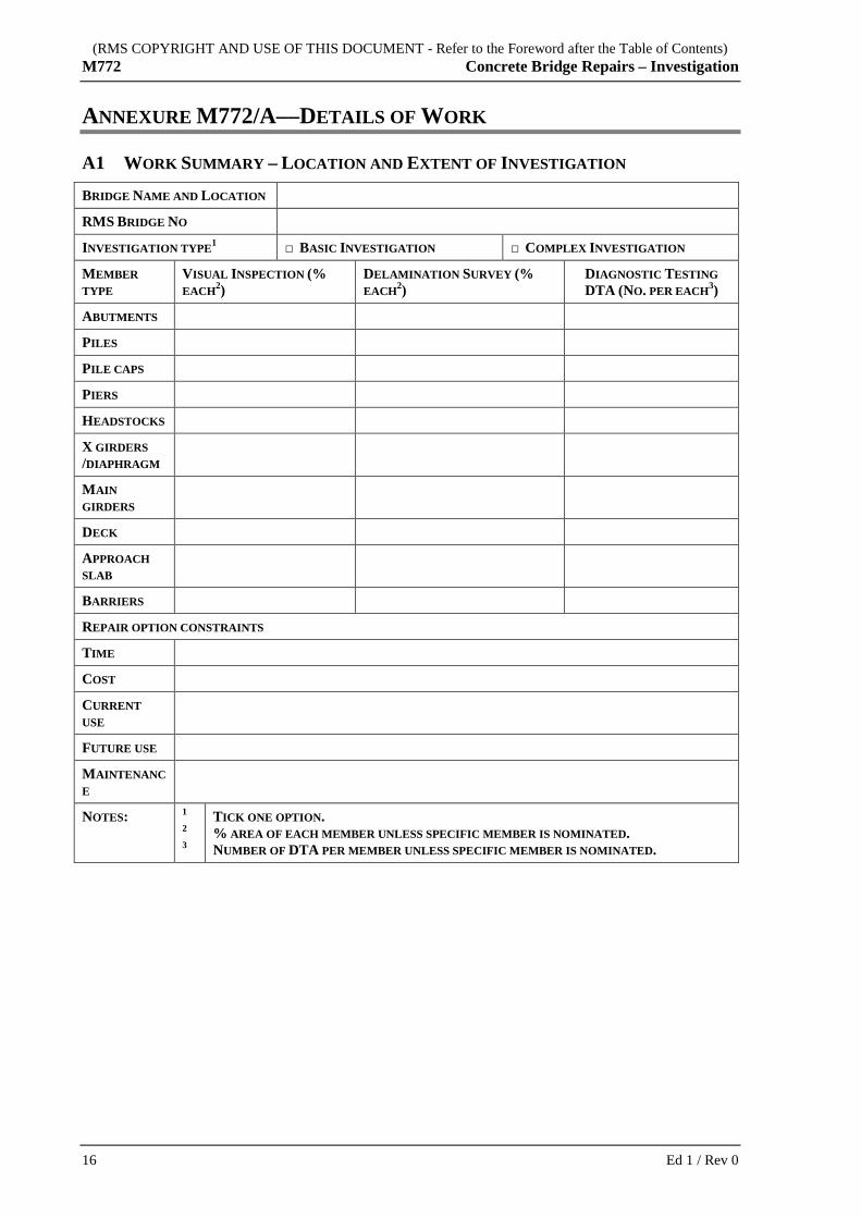
A1 WORK SUMMARY – LOCATION AND EXTENT OF INVESTIGATION
BRIDGE NAME AND LOCATION
RMS BRIDGE NO
INVESTIGATION TYPE1 □ BASIC INVESTIGATION □ COMPLEX INVESTIGATION
MEMBER TYPE
VISUAL INSPECTION (% EACH2)
DELAMINATION SURVEY (% EACH2)
DIAGNOSTIC TESTING DTA (NO. PER EACH3)
ABUTMENTS
PILES
PILE CAPS
PIERS
HEADSTOCKS
X GIRDERS /DIAPHRAGM
MAIN GIRDERS
DECK
APPROACH SLAB
BARRIERS
REPAIR OPTION CONSTRAINTS
TIME
COST
CURRENT USE
FUTURE USE
MAINTENANCE
NOTES: 1
2
3
TICK ONE OPTION. % AREA OF EACH MEMBER UNLESS SPECIFIC MEMBER IS NOMINATED. NUMBER OF DTA PER MEMBER UNLESS SPECIFIC MEMBER IS NOMINATED.
16 Ed 1 / Rev 0

(RMS COPYRIGHT AND USE OF THIS DOCUMENT - Refer to the Foreword after the Table of Contents) Concrete Bridge Repairs – Investigation M772
A2 WORK SUMMARY- NUMBER OF DIAGNOSTIC TESTS IN EACH DTA D
IAG
NO
STIC
T
EST
1
CO
VE
RM
ETE
R S
UR
VE
Y
P OT
EN
TIA
L S
UR
VE
Y
CH
LO
RID
E/S
UL
PHA
TE
AN
AL
YSI
S
CA
RB
ON
AT
ION
TE
STIN
G
RE
SIST
IVIT
Y T
EST
ING
AA
R P
ET
RO
GR
APH
IC
EX
AM
INA
TIO
N
AA
R R
API
D
IDE
NT
IFIC
AT
ION
STE
EL A
NA
LY
SIS
CH
EM
ICA
L/
TE
NSI
LE
/
CO
MPR
ESS
IVE
ST
RE
NG
TH
AN
D
MO
DU
LU
S O
F
MEMBER1 TYPE
ABUTMENTS
PILES
PILE CAPS
PIERS
HEADSTOCKS
X GIRDERS /DIAPHRAGM
MAIN GIRDERS
DECK2
APPROACH SLAB
BARRIERS
NOTES:
1 PRINCIPAL TO ENTER THE NUMBER OF DIAGNOSTIC TESTS FOR EACH DTA ON A GIVEN MEMBER TYPE.
2 FOR LARGE DECK AREAS A POTENTIAL WHEEL WITH READINGS TAKEN EQUIVALENT TO THE SPECIFIED GRID SPACING MAY BE USED.
Ed 1 / Rev 0 17
(RMS COPYRIGHT AND USE OF THIS DOCUMENT - Refer to the Foreword after the Table of Contents) M772 Concrete Bridge Repairs – Investigation
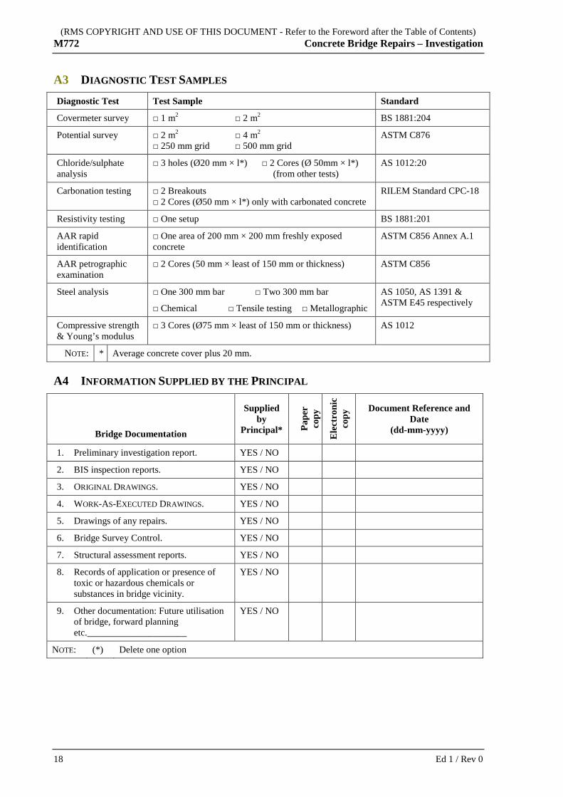
A3 DIAGNOSTIC TEST SAMPLES
Diagnostic Test Test Sample Standard
Covermeter survey □ 1 m2 □ 2 m2 BS 1881:204
Potential survey □ 2 m2 □ 4 m2 □ 250 mm grid □ 500 mm grid
ASTM C876
Chloride/sulphate analysis
□ 3 holes (Ø20 mm × l*) □ 2 Cores (Ø 50mm × l*) (from other tests)
AS 1012:20
Carbonation testing □ 2 Breakouts □ 2 Cores (Ø50 mm × l*) only with carbonated concrete
RILEM Standard CPC-18
Resistivity testing □ One setup BS 1881:201
AAR rapid identification
□ One area of 200 mm × 200 mm freshly exposed concrete
ASTM C856 Annex A.1
AAR petrographic examination
□ 2 Cores (50 mm × least of 150 mm or thickness) ASTM C856
Steel analysis □ One 300 mm bar □ Two 300 mm bar
□ Chemical □ Tensile testing □ Metallographic
AS 1050, AS 1391 & ASTM E45 respectively
Compressive strength & Young’s modulus
□ 3 Cores (Ø75 mm × least of 150 mm or thickness) AS 1012
NOTE: * Average concrete cover plus 20 mm.
A4 INFORMATION SUPPLIED BY THE PRINCIPAL
Bridge Documentation
Supplied by
Principal* Pape
r
copy
Ele
ctro
nic
copy
Document Reference and Date
(dd-mm-yyyy)
1. Preliminary investigation report. YES / NO
2. BIS inspection reports. YES / NO
3. ORIGINAL DRAWINGS. YES / NO
4. WORK-AS-EXECUTED DRAWINGS. YES / NO
5. Drawings of any repairs. YES / NO
6. Bridge Survey Control. YES / NO
7. Structural assessment reports. YES / NO
8. Records of application or presence of toxic or hazardous chemicals or substances in bridge vicinity.
YES / NO
9. Other documentation: Future utilisation of bridge, forward planning etc._____________________
YES / NO
NOTE: (*) Delete one option
18 Ed 1 / Rev 0

(RMS COPYRIGHT AND USE OF THIS DOCUMENT - Refer to the Foreword after the Table of Contents) Concrete Bridge Repairs – Investigation M772
ANNEXURE M772/B––MEASUREMENT AND PAYMENT
B1 GENERAL
B1.1 Pay Items are identified in ANNEXURE M772/B2. Pay Items
B1.2 Price pay items in the schedule of pay items taking into account all the costs associated with doing the work.
Include the cost of any unpriced pay items in the priced pay items.
Prices
B1.3 Distribute overheads between priced pay items. Overheads
B1.4 Pay items with a specified quantity of work must not be tendered as a lump sum.
No Lump Sum
B1.5 Pay Item 909 applies for work relating to provision for traffic. Provision for traffic
B1.6 You will not be paid for work that does not conform to the Specification.
No payment
B2 SCHEDULE OF PAY ITEMS Maintenance Activity Code Item Name and Description Units of
Measurement
772.01 Field assessment Each
.1 Desktop review of Principal-supplied information
.2 Visual inspection
.3 Delamination survey
.4 Diagnostic testing
772.02 Investigation report Each
.1 Reporting condition of inspected members
.2 Defect mapping
.3 Diagnostic test results and their analysis
.4 Defect causes
.5 Mitigation, repair options and repair methods
Ed 1 / Rev 0 19

(RMS COPYRIGHT AND USE OF THIS DOCUMENT - Refer to the Foreword after the Table of Contents) M772 Concrete Bridge Repairs – Investigation
ANNEXURE M772/C––SCHEDULES OF HOLD POINTS AND IDENTIFIED RECORDS
C1 SCHEDULE OF HOLD POINTS
Clause Type Process Held Submission Details
2.1.3 Hold Commencement of Work. At least 10 BUSINESS DAYS prior to the planned date of commencement of work, submit:
.1 The PROJECT QUALITY PLAN conforming to Clause 2.1.3.
.2 The Project WORK HEALTH AND SAFETY MANAGEMENT PLAN (refer Clause 2.2).
.3 The TRAFFIC CONTROL PLAN (TCP) (refer Clause 2.2).
4.3.1.4 Hold Erection of accesses and scaffolding.
Submit details of accesses and/or scaffolding including design calculations and Engineer’s certification, at least 10 Business Days prior to erection of the accesses or scaffolding.
4.3.4.2 Hold Selection of DTA locations. Drawings nominating DTA locations at least 10 Business Days prior to commencing diagnostic testing.
4.3.4.8 Hold Core drilling of prestressed members.
Core drill locations and certificate from a Structural Engineer at least 10 Business Days prior to commencing diagnostic testing.
C2 SCHEDULE OF IDENTIFIED RECORDS
Clause Description of Identified Record
2.1.1 PROJECT QUALITY PLAN.
2.2.1 Project WORK HEALTH AND SAFETY MANAGEMENT PLAN.
2.2.2 TRAFFIC CONTROL PLAN (TCP).
4.2.5 Investigation report.
4.3.1.11 Photographs.
4.3.1.16 Drawings mapping defects.
20 Ed 1 / Rev 0
(RMS COPYRIGHT AND USE OF THIS DOCUMENT - Refer to the Foreword after the Table of Contents) Concrete Bridge Repairs – Investigation M772
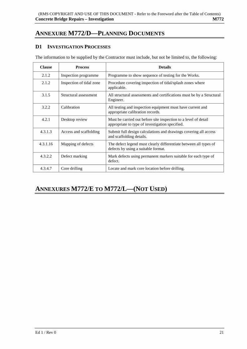
ANNEXURE M772/D––PLANNING DOCUMENTS
D1 INVESTIGATION PROCESSES
The information to be supplied by the Contractor must include, but not be limited to, the following:
Clause Process Details
2.1.2 Inspection programme Programme to show sequence of testing for the Works.
2.1.2 Inspection of tidal zone Procedure covering inspection of tidal/splash zones where applicable.
3.1.5 Structural assessment All structural assessments and certifications must be by a Structural Engineer.
3.2.2 Calibration All testing and inspection equipment must have current and appropriate calibration records.
4.2.1 Desktop review Must be carried out before site inspection to a level of detail appropriate to type of investigation specified.
4.3.1.3 Access and scaffolding Submit full design calculations and drawings covering all access and scaffolding details.
4.3.1.16 Mapping of defects The defect legend must clearly differentiate between all types of defects by using a suitable format.
4.3.2.2 Defect marking Mark defects using permanent markers suitable for each type of defect.
4.3.4.7 Core drilling Locate and mark core location before drilling.
ANNEXURES M772/E TO M772/L––(NOT USED)
Ed 1 / Rev 0 21

(RMS COPYRIGHT AND USE OF THIS DOCUMENT - Refer to the Foreword after the Table of Contents) M772 Concrete Bridge Repairs – Investigation
ANNEXURE M772/M–––REFERENCED DOCUMENTS AND DEFINITIONS
M1 REFERENCE DOCUMENTS
M1.1 Australian Standards
AS 1012 Methods of testing concrete
AS 1391 Metallic materials – Tensile testing at ambient temperature
AS/NZS 1050 Methods for the analysis of iron and steel
AS/NZS 1349 Bourdon tube pressure and vacuum gauges
AS/NZS 4536:1999 Life cycle costing – An application guide
AS HB 84 Guide to Concrete Repair and Protection
M1.2 International Standards
ASTM C856-4 Standard Practice for Petrographic Examination of Hardened Concrete
ASTM C856 A1 Rapid Identification of Alkali-Silica Reaction Products in Concrete
ASTM C876 Standard Test Method for Half-Cell Potentials of Uncoated Reinforcing Steel in Concrete
ASTM D4580-03 Standard Practice for Measuring Delaminations in Concrete Bridge Decks by Sounding
ASTM E45-05 Standard Test Methods for Determining the Inclusion Content of Steel
BS 1881: 201 Testing concrete. Guide to the use of non-destructive methods of test for hardened concrete.
BS 1881: 204 Testing concrete. Recommendations on the Use of Electromagnetic Covermeters.
RILEM CPC 18 RILEM: Measurement for Hardened Concrete Carbonation Depth, TC14-CPC, CPC-18, 1988
M1.3 RMS Specifications
RMS G22 Work Health and Safety (Construction and Maintenance Works)
RMS G71 Construction Surveys
RMS Q Quality Management System
M2 ABBREVIATIONS
PQP PROJECT QUALITY PLAN
NDT/I Non Destructive Testing/Inspection
TCP TRAFFIC CONTROL PLAN
22 Ed 1 / Rev 0

(RMS COPYRIGHT AND USE OF THIS DOCUMENT - Refer to the Foreword after the Table of Contents) Concrete Bridge Repairs – Investigation M772
M3 DEFINED TERMS
BASIC INVESTIGATION An investigation that meets the objectives of Clause 4.2.3
Business Day Any day other than a Saturday, Sunday or public holiday or 27, 28, 29, 30 or 31 December
COMPLEX INVESTIGATION An investigation that meets the objectives of Clause 4.2.4
HOLD POINT A point beyond which a work process must not proceed without the Principal's express written authorisation (refer RMS Q)
ORIGINAL DRAWINGS The original bridge design drawings or original WORK-AS-EXECUTED DRAWINGS
Principal Means the NSW Roads and Maritime Services
PROJECT QUALITY PLAN Refer to Clause 2.1
Specification Means M772
Structural Engineer A Chartered Professional Engineer with membership of Engineers Australia practising in the field of structural engineering (or equivalent). An equivalent to membership of Engineers Australia would be an Engineer registered on the National Professional Engineers Register (NPER) in the general area of practice of Civil Engineering and experienced in structural engineering
TRAFFIC CONTROL PLAN Refer Clause 2.2.2
Work The scope of work covered by the Specification under the Contract (refer ANNEXURE M772/A, Clause 1 and RMS Q)
WORK-AS-EXECUTED DRAWINGS
Drawings recording details of the completed Work
You Means the Contractor, including subcontractors, employees and agents of the contractor
M4 DEFINITIONS
The following definitions apply to this Specification:
Term Alternative Term
Definitions
Abrasion Progressive loss of material from the concrete surface
Bridge Information System
General term for the approved RMS bridge inspection and condition rating reporting system and its database
Bridge Survey Control
The survey control network for the bridge (refer to RMS G71)
Dampness Wet or moist areas of concrete evidenced by the different colour of the concrete surface
Efflorescence Deposition of white salts or lime mortar on the concrete surface
Member Component Element
Any member or part of a member acting as part of a structural assembly
Ed 1 / Rev 0 23

(RMS COPYRIGHT AND USE OF THIS DOCUMENT - Refer to the Foreword after the Table of Contents) M772 Concrete Bridge Repairs – Investigation
Term Alternative
Term Definitions
Honeycombing Voids or spaces within concrete, usually caused by lack of adequate compaction
Live cracks Cracks showing progressive growth, excluding thermal cyclic opening/closing
Rust staining Brown or rust coloured stains
Scaling Local flaking or peeling away of the surface of the hardened concrete or mortar
Site Supervisor The Works Supervisor supervising the Works at the Bridge Site
Spalling Concrete fragments detached from the parent concrete
Substrate The cleaned and roughened surface to which the repair material is applied
Temporary works All works which are not part of the permanent repair but are required before or during completion of permanent repairs, including, but not limited to: interim repairs, access and scaffolding, temporary bracing and supports (e.g. supplementary bearings, shoring, blocking, and cribbing)
Weathering Changes in concrete properties, such as colour, texture or strength, resulting from exposure to the environment
….
24 Ed 1 / Rev 0