m8000md commercial snow blower operator's manual · 2006-03-28 · and the snow blower is...
TRANSCRIPT

© 2004 Alamo Group Inc.
Published 12/04 Part No. 5040C
OPERATOR'S MANUALThis Operator's Manual is an integral part of the safe operationof this machine and must be maintained with the unit at alltimes. READ, UNDERSTAND, and FOLLOW the Safety andOperation Instructions contained in this manual beforeoperating the equipment.
M8000MD COMMERCIAL SNOW BLOWER
$0.00
ALAMO INDUSTRIAL1502 E. WalnutSeguin, Texas 78155210-372-3551

TO THE OWNER/OPERATOR/DEALERAll implements with moving parts are potentially hazardous. There is no substitute for a cautious, safe-mindedoperator who recognizes the potential hazards and follows reasonable safety practices. The manufacturer hasdesigned this implement to be used with all its safety equipment properly attached to minimize the chance ofaccidents.
BEFORE YOU START!! Read the safety messages on the implement and shown in your manual.Observe the rules of safety and common sense!
WARRANTY INFORMATION:
Read and understand the complete Warranty Statement found in this Manual. Fill out the Warranty Registration Formin full and return it to Alamo within 30 Days. Make certain the Serial Number of the Machine is recorded on theWarranty Card and on the Warranty Form that you retain.

© 2004 Alamo Group Inc.
TABLE OF CONTENTS
SAFETY SECTION
Safety Information ........................................................................................................................... 1-2Safety Decal Location .................................................................................................................... 1-18Safety Decals .................................................................................................................................. 1-20Federal Laws and Regulations ....................................................................................................... 1-28
INTRODUCTION SECTION ................................................................................................................... 2-1
ASSEMBLY SECTION .......................................................................................................................... 3-1
Spout Installation ......................................................................................................................... 3-2Connection Hydraulic Hoses to Snowblower ........................................................................... 3-4Turning on Power Unit ................................................................................................................ 3-5
OPERATION SECTION ......................................................................................................................... 4-1
MAINTENANCE SECTION .................................................................................................................... 5-1
General Maintenance ............................................................................................................................. 5-2Nuts and Bolts ....................................................................................................................................... 5-2Drive Assembly ...................................................................................................................................... 5-2Shear Bolt .............................................................................................................................................. 5-2PTO Lubrication ..................................................................................................................................... 5-2Chute Lubrication ................................................................................................................................... 5-2Oil Reservoir ........................................................................................................................................... 5-3Clutch Adjustment ................................................................................................................................. 5-4Chain Tightening Instructions ................................................................................................................ 5-8Storage................................................................................................................................................... 5-9Maintenance Schedule .......................................................................................................................... 5-10
TRANSFLUID SECTION ....................................................................................................................... 6-1
OMNEX SECTION ................................................................................................................................. 7-1
Alamo Industrial is registered trademark of Alamo Group Inc.
ENGINE MANUAL
The Engine Manual is shipped with machine, and is supplied by Engine Manufacturer and should be consulted forengine maintenance care, and engine repair component part numbers.

SAFETYSECTION
Safety Section 1-1
© 2004 Alamo Group Inc.

Safety Section 1-2M-8000MD 12/04
SAFETY
© 2004 Alamo Group Inc.
SA
FE
TY
A safe and careful operator is the best operator. Safety is of primary importance to themanufacturer and should be to the owner/operator. Most accidents can be avoided by beingaware of your equipment, your surroundings, and observing certain precautions. The first sectionof this manual includes a list of Safety Messages that, if followed, will help protect the operatorand bystanders from injury or death. Read and understand these Safety Messages beforeassembling, operating or servicing this implement. This equipment should only be operated bythose persons who have read the Manual, who are responsible and trained, and who know how
to do so safely and responsibly.
The Safety Alert Symbol combined with a Signal Word, as seen below, is used throughout thismanual and on decals which are attached to the equipment. The Safety Alert Symbol means:“ATTENTION! BECOME ALERT! YOUR SAFETY IS INVOLVED!” The Symbol and SignalWord are intended to warn the owner/operator of impending hazards and the degree ofpossible injury faced when operating this equipment..
CAUTION! The lowest level of Safety Message; warns of possible injury. Decals located on the Equipment with this Signal Word are Black and Yellow.
WARNING! Serious injury or possible death! Decals are Black and Orange.
DANGER! Imminent death/critical injury. Decals are Red and White. (SG-1)
Practice all usual and customary safe working precautions andabove all---remember safety is up to YOU. Only YOU can preventserious injury or death from unsafe practices.
READ, UNDERSTAND, and FOLLOW the following SafetyMessages. Serious injury or death may occur unless care istaken to follow the warnings and instructions stated in the SafetyMessages. Always use good common sense to avoid hazards.
(SG-2)
General Safety Instructions and Practices

Safety Section 1-3
SAFETY
© 2004Alamo Group Inc.
SA
FE
TY
M-8000MD 12/04
Si no lee Ingles, pida ayuda a alguien que si lo lea para que letraduzca las medidas de seguridad. (SG-3)
PELIGRO!
!LEA EL INSTRUCTIVO!
WARNING! Engine Exhaust, some of its constituents, and certain vehicle componentscontain or emit chemicals known to the state of California to cause cancerand birth defects or other reproductive harm. (SG-30)
WARNING! Battery posts, terminals and related accessories contain lead and leadcompounds, chemicals known to the state of California to causecancer and birth defects or other reproductive harm. Wash Hands afterhandling. (SG-31)
Operator Safety Instructions and Practices
WARNING! The operator and all support personnel should wear hard hats, safetyshoes, safety glasses, and proper hearing protection at all times forprotection from injury including injury from items thrown by theequipment. (SG-16)
DANGER! Never operate the Power Unit or Implement until you have read andcompletely understand this Manual, the Power Unit Operator’s Manual,and each of the Safety Messages found in the Manual or on the PowerUnit and Implement. Learn how to stop the Power Unit enginesuddenly in an emergency. Never allow inexperienced or untrainedpersonnel too operate the Power Unit and Implement without supervision.Make sure the operator has fully read and understood the manualsprior to operation. (SPU-36)
CAUTION! PROLONGED EXPOSURE TO LOUD NOISE MAY CAUSEPERMANENT HEARING LOSS! Power Units with or without anImplement attached can often be noisy enough to cause permanenthearing loss. We recommend that you always wear hearingprotection if the noise in the Operator’s position exceeds 80db.Noise over 85db over an extended period of time will cause severehearing loss. Noise over 90db adjacent to the Operator over anextended period of time will cause permanent or total hearing loss.Note: Hearing loss from loud noise [from power units, chain saws,radios, and other such sources close to the ear] is cumulative overa lifetime without hope of natural recovery. (SPU-20)

Safety Section 1-4M-8000MD 12/04
SAFETY
© 2004 Alamo Group Inc.
SA
FE
TY
WARNING! Always read carefully and comply fully with the manufacturers instructionswhen handling oil, solvents, cleansers, and any other chemical agent.(SG-22)
DANGER! KEEP AWAY FROM ROTATING ELEMENTS to prevent entanglementand possible serious injury or death. (SG-24)
WARNING! Use extreme caution when getting onto the Implement to performrepairs, maintenance and when removing accumulated material. Onlystand on solid flat surfaces to ensure good footing. Use a ladder orraised stand to access high spots which cannot be reached fromgound level. Slipping and falling can cause serious injury or death.(SG-33)
Never allow children to play on or around the Power Unit or Implement.Children can slip or fall off the Equipment and be injured or killed.Children can cause the Implement to shift or fall crushing themselves orothers. (SPU-24)
DANGER!
NEVER use drugs or alcohol immediately before or while operating thePower Unit and Implement. Drugs and alcohol will affect an operator’salertness and coordination and therefore affect the operator’s ability tooperate the equipment safely. Before operating the Power Unit orImplement, an operator on prescription or over-the-counter medicationmust consult a medical professional regarding any side effects of themedication that would hinder their ability to operate the Equipmentsafely. NEVER knowingly allow anyone to operate this equipmentwhen their alertness or coordination is impaired. Serious injury ordeath to the operator or others could result if the operator is underthe influnce of drugs or alcohol. (SPU-25)
DANGER!
WARNING! Prolonged operation may cause operator boredom and fatigue affectingsafe operation. Take scheduled work breaks to help prevent thesepotentially impaired operating conditions. Never operate the Implementand Power Unit in a fatigued or bored mental state which impairs properand safe operation. (SPU-37)

Safety Section 1-5
SAFETY
© 2004Alamo Group Inc.
SA
FE
TY
M-8000MD 12/04
WARNING! Avoid contact with hot surfaces of the engine or muffler. Use glovesand eye protection when servicing hot components. Contact with a hotsurface or fluid can cause serious injury from burns or scalding.(SG-38)
WARNING! The rotating parts of this machine continue to rotate a short period of timeeven after the Power Unit has been turned off. The operator shouldremain in his seat for 20 seconds AFTER the parking brake has been set,the auxiliary hydraulics disengaged, the Power Unit turned off, and allevidence of rotation has ceased. (SPU-4)
“Wait a minute...Save a life!”
DANGER! Do Not approach the front of the snow blower while the fan is rotating.Contact with the rotating fan can result in serious injury or even death.Stay away until all motion has stopped and the snow blower is securelyblocked up before removing material, performing service, and makingrepairs. (SSB-05a)
DANGER! Do not put hands or feet near the rotating fan. Fan contact can resultin serious injury or even death. Stay away until all motion has stoppedand the snow blower is securely blocked up before removing material,performing service, and making repairs. (SSB-6)
DANGER! Do not operate the implement while wearing loose fitting clothing.Entanglement of the clothing with the rotating elements can result inserious injury or even death. Stay clear of all rotating elements at alltimes. (SSP-3)
WARNING! Avoid contact with hot surfaces including hydraulic oil tanks, pumps,motors, valves and hose connections. Relieve hydraulic pressurebefore performing maintenance or repairs. Use gloves and eyeprotection when servicing hot components. Contact with a hot surfaceor fluid can cause serious injury from burns or scalding. (SG-34)
DANGER! DO NOT operate this Implement on a Power Unit that is not properlymaintained. Should a mechanical or Power Unit control failure occurwhile operating, immediately shut down the Power Unit and performrepairs before resuming operation. Serious injury and possible deathcould occur from not maintaining this Implement and Power Unit ingood operating condition. (SPU-38)

Safety Section 1-6M-8000MD 12/04
SAFETY
© 2004 Alamo Group Inc.
SA
FE
TY
Equipment Operation Safety Instructions and Practices
Connecting or Disconnecting Implement Safety Instructions and Practices
DANGER! Always shut the Power Unit completely down, place the transmission inpark, and set the parking brake before you or anyone else attempts to connector disconnect the Implement and Power Unit hitches. (SPU-32)
DANGER! Never allow children or other persons to ride on the Power Unit or Implement.Falling off can result in serious injury or death. (SPU-16)
DANGER! Never allow children to operate or ride on the Power Unit or Implement.(SPU-17)
DANGER! Do not mount the Power Unit while the Power Unit is moving. Mount thePower Unit only when the Power Unit and all moving parts arecompletely stopped. (SPU-18)
DANGER! Start the Power Unit only when properly seated in the Power Unit seat.Starting a Power Unit in gear can result in injury or death. Read thePower Unit Operator’s Manual for proper starting instructions. (SPU-19)
Safety Section 1-7
SAFETY
© 2004Alamo Group Inc.
SA
FE
TY
M-8000MD 12/04
DANGER! Do not operate this Equipment with hydraulic oil or fuel leaking. Oiland fuel are expensive and their presence could present a hazard.Do not check for leaks with your hand! High-pressure oil streamsfrom breaks in the line could penetrate the skin and cause tissuedamage including gangrene. To check for a hose leak, SHUT theENGINE OFF and remove all hydraulic pressure. Wear oilimpenetrable gloves, safety glasses and use Cardboard tocheck for evidence of oil leaks. If you suspect a leak, RE-MOVE the HOSE and have it tested at a Dealer. If oil doespenetrate the skin, have the injury treated immediately by a physi-cian knowledgeable and skilled in this procedure. (SG-15)
DANGER! Operate the Power Unit and/or Implement controls only while properlyseated in the Power Unit seat with the seat belt securely fastened aroundyou. Inadvertent movement of the Power Unit or Implement may causeserious injury or death. (SPU-26)
WARNING! In case of mechincal difficulty during operation, place the transmission inthe park position, set the parking brake, shut down all power, includingthe implement and remove the key. Wait until all rotating motion hasstop before dismounting. (SPU-39)
DANGER! The center of gravity of a Power Unit equipped with a front-mountedImplement is shifted to the front and removes weight from the rear wheels.The Power Unit should maintain at least 20% total weight on the rearwheels to prevent tipping forward, loss of steering control, and possibleinjury. Add counterweight if required when operating on slopes andproceed with the load uphill to prevent tipping. Reference the PowerUnit’s Operator’s Manual or an authorized dealer for information onadding additional weight. (SPU-6)
Operate this Equipment only with a Power Unit equipped with anapproved operator Roll-Over Protective Structure (ROPS). Alwayswear seat belts. Serious injury or even death could result from fallingoff the Power Unit--particularly during a turnover when the operatorcould be pinned under the Operator Protective Structure. (SPU-14)
WARNING!

Safety Section 1-8M-8000MD 12/04
SAFETY
© 2004 Alamo Group Inc.
SA
FE
TY
WARNING! Extreme care should be taken when operating near loose objects suchas gravel, rocks, wire and other debris. Foreign objects should beremoved from the site to prevent machine damage and/or bodily injuryor even death. Any object that cannot be removed must be clearlymarked and carefully avoided by the operator. Stop snow blowingimmediately if the auger or fan strikes a foreign object. Repair alldamage before resuming snow blowing. (SSB-2)
WARNING! Many varied objects, such as wire, cable, rope, or chains can becomeentangled in the operating parts of the Snow Blower. These itemscould then swing outside the housing at high speeds. Such a situationis extremely hazardous and could result in serious injury or evendeath. Inspect the work area for such objects before snow blowing.Remove any like object from the site. Never allow the auger to contactsuch items. (SSB-3)
WARNING! Blow snow at the speed that you can safely operate and control theTractor and Snow Blower. Safe speed depends on terrain and snowconditions. Normal ground speed range is from 0 to 5 mph. Use slowspeeds when operating on or near steep slopes, ditches, drop-offs,overhead obstructions, power lines, or when debris and foreign objectsare to be avoided. (SSB-4)
DANGER! BEFORE leaving the Power Unit seat, always engage the brake and setthe Power Unit transmission in parking gear, disengage the auxiliaryhydraulics, stop the engine, remove the key, and wait for all moving partsto stop. Place the Power Unit shift lever into a low range or parking gearto prevent the tractor from rolling. Never dismount a Power Unit that ismoving or while the engine is running. Operate the Power Unit controlsfrom the operator seat only. (SPU-15)
WARNING! Only operate the snow blower in conditions were you have clearvisibility in daylight or with adequate artificial lighting. Never snowblow in darkness or in conditions where you cannot clearly see at least100 yards in front and to the sides of the Power Unit and Snow Blower.Make sure that you can clearly see and identify passersby, steepslopes, ditches, drop-offs, overhead obstructions, power lines, debrisand foreign objects. If you are unable to clearly see these types ofitems, discontinue snow blowing. (SSB-1)

Safety Section 1-9
SAFETY
© 2004Alamo Group Inc.
SA
FE
TY
M-8000MD 12/04
DANGER! Snow Blowers are capable under adverse conditions of throwing objectsfor great distances (200 feet or more). Do not allow the snow stream tofall on passersby. Ice, debris and heavy snow thrown from the snowblower can cause serious injury or death. (SSB-7)
STOP SNOW BLOWING IF PASSERSBY ARE WITHIN 200 FEET.
DANGER! There are obvious and hidden potential hazards in the operation of thisSnow Blower. REMEMBER! This machine is often operated in deepsnow where vision is reduced. The fan blades of this Snow Blower canthrow objects for great distances Serious injury or even death may occurunless care is taken to insure the safety of the operator, bystanders, orpassersby in the area. Do not operate this machine with anyone in theimmediate area. Stop Snow Blowing if anyone is within 200 feet of SnowBlower. (SSB-11)
DANGER! The rotating parts of this machine have been designed and tested forrugged use. However, the blades and rotating members could fail uponimpact with heavy, solid objects such as metal guard rails and concretestructures. Such impact could cause the broken objects to be thrownoutward at very high velocities. To reduce the possibility of propertydamage, serious injury, or even death, never allow the rotating bladesto contact such obstacles. (SSB-13)
WARNING! When blowing snow with two machines in the same area be sure thatwindows are closed. (SSB-10)
WARNING! Do not operate Snow Blower if excessive vibration exists. Shut downPower Unit and Implement engines. Inspect the Snow Blower todetermine the source of the vibration. If blades are missing ordamaged replace them immediately. Do not operate the Snow Bloweruntil the blades have been replaced and the Blower operates smoothly.Operating the Snow Blower with excessive vibration can result incomponent failure and broken objects to be thrown outward at veryhigh velocities. To reduce the possibility of property damage, seriousinjury, or even death, never allow the Snow Blower to be operated withblades missing. (SSB-32)

Safety Section 1-10M-8000MD 12/04
SAFETY
© 2004 Alamo Group Inc.
SA
FE
TY
DANGER! Always keep a careful lookout and use extreme care when workingaround utility lines. Never allow the Snow Blower within 10 feet of anyUtility power or gas line. Heavy snow or ice storms can cause utilitylines to sage or drop to the ground. Do not operate this equipmentwhere power lines are on the ground. When working close to Utilitylines consult your electric or gas company for a safe code of operation.(SSB-15)
WARNING! Before dismounting to clear a clogged machine, place the transmissionin the park position, set the parking brake, shut down all power, includingthe PTO and the engine and remove the key. Wait until all rotatingmotion has stop before dismounting. (SSB-16)
WARNING! Snow can cover and hide solid objects such as guard rails, curbs, con-crete structures, large rocks, utility boxes, fire hydrants, etc. DO NOTallow the rotating parts of the Snow Blower to contact such items. In-spect the area before operating the Snow Blower. Mark all solid itemsclearly with a pole and flag. To reduce the possibility of propertydamage, serious injury, or even death, never allow the rotating bladesto contact such obstacles. (SSB-20)
WARNING! The Snow Blower can block the operators vision directly in front of theSnow Blower. Inspect the area before operating the Snow Blowerand make sure that there are no obstacles, passersby, or coworkersin the path of the Snow Blower. (SSB-22)
DANGER! Start the Power unit and Auxiliary engines only when seated andbelted in the operator seat. Operate the Snow blower controls onlywhile seated with the seat belt secured around you. Inadvertentmovement of the Power unit and/or Snow Blower components maycause serious injury or death to the operator and passersby. Read thePower Unit and Auxiliary Engine operator’s manuals for properstarting instructions. (SSB-24)
WARNING! Never run the Power unit or Auxiliary engine in a closed building orwithout adequate ventilation. The exhaust fumes can be hazardousand deadly to your health. If it is necessary to run the Power unit orAuxiliary engine in an enclosed area, remove the exhaust fumesfrom the area to the outdoors with an exhaust pipe extension. If youdo not have an exhaust pipe extension, or if it is not possible to useone, open doors and circulate outside air into the area. (SSB-30)
Safety Section 1-11
SAFETY
© 2004Alamo Group Inc.
SA
FE
TY
M-8000MD 12/04
WARNING! Transport only at safe speeds. Serious accidents and injuries can resultfrom operating this equipment at unsafe speeds. Understand the PowerUnit and Implement and how it handles before transporting on streets andhighways. Make sure the Power Unit steering and brakes are in goodcondition and operate properly.
Before transporting the Power Unit and Implement, determine the safetransport speeds for you and the equipment. Make sure you abide bythe following rules:
Be aware of the operating conditions. Do not operate the Power Unit withweak or faulty brakes. When operating down a hill or on wet or rain slickroads, the braking distance increases: use extreme care and reduce yourspeed. When operating in traffic always use the Power Unit's flashingwarning lights and reduce your speed. Be aware of traffic around you andwatch out for the other guy. (SPU-21)
Test the equipment at a slow speed in turns. Increase the speedthrough the turn only after you determine that it is safe to operateat a higher speed. Use extreme care and reduce your speed whenturning sharply to prevent the tractor and implement from turningover. Determine the maximum safe turning speed for you and thisequipment before operating on roads or uneven ground.Only transport the Power Unit and Implement at the speeds that youhave determined are safe and which allow you to properly control theequipment.
Test the Power Unit at a slow speed and increase the speed slowly.Apply the Brakes smoothly to determine the stoppingcharacteristics of the Power Unit and Implement.As you increase the speed of the Power Unit the stopping distanceincreases. Determine the maximum safe transport speed foryou and this Equipment.
2.
1.
3.
WARNING! Before transporting the Snow Blower, position the snow dischargeshoot in the center position to reduce the possibility of blocking theoperators vision. (SSB-21)
DANGER! Be particularly careful in transport. The Implement has raised andmoved the center of gravity to the front of the Power Unit increasing thepossibility of overturn and tipping forward. Turn curves or go up slopesonly at low speed and using a gradual turning angle. Go up slopes withthe Implement located uphill. Slow down on rough or uneven surfaces.(SPU-2)
WARNING! When in transport, only raise the Implement to a height sufficient tosafely clear ground obstructions. Maximum transport height is 18”.Transport the Implement in a near level position and never obstructvisibility to the front of the Implement during transport. (SSB-23)
Transporting Safety Instructions and Practices
WARNING! Make certain that the “Slow Moving Vehicle” (SMV) sign is installed in sucha way as to be clearly visible and legible. When transporting the Equipmentuse the Power Unit flashing warning lights and follow all local trafficregulations. (SPU-40)

Safety Section 1-12M-8000MD 12/04
SAFETY
© 2004 Alamo Group Inc.
SA
FE
TY
Maintenance and Service Safety Instructions and PracticesDANGER! Make sure the PTO shield, integral driveline shields, and input shields are
installed when using PTO-driven equipment. Always replace any shield ifit is damaged or missing. (S3PT-8)
WARNING! Never interfere with factory-set hydraulic calibrations. Any change incalibration could cause a failure of the equipment and may result in injury.(SBH-13)
WARNING! Always maintain the safety decals in good readable condition. If thedecals are missing, damaged, or unreadable, obtain and install replace-ment decals immediately. (SG-5)
WARNING! Do not modify or alter this Implement. Do not permit anyone to modifyor alter this Implement, any of its components or any Implementfunction. (SG-8)
WARNING! Periodically inspect all moving parts for wear and replace when neces-sary with authorized service parts. Look for loose fasteners, worn orbroken parts, and leaky or loose fittings. Make sure all pins have cotterpins and washers. Serious injury may occur from not maintaining thismachine in good working order. (SG-21)
WARNING! Your driving vision may be reduced or impaired by the cab, or implement.Before driving on public roadways identify any limited vision areas, andmake adjustments to your operating position, mirrors, and the implementtransport position so that you can clearly see the area where you will betraveling, and any traffic that may approach you. Failure to maintainadequate vision of the public roadway and traffic can result in serious injuryor even death. (STI-10)
WARNING! Relieve hydraulic pressure prior to doing any maintenance or repairwork on the Implement. Place the Mower Head on the ground orsecurely supported on blocks or stands, disengage the auxiliaryhydraulics, and turn off the engine. Push and pull the Control Leversseveral times to relieve pressure prior to starting any maintenance orrepair work. (SPU-34)
WARNING! Never attempt to lubricate, adjust, or remove material from the Implementwhile it is in motion or while the Power Unit engine is running. Makesure the Power Unit is off before working on the Implement. (SPU-22)
Safety Section 1-13
SAFETY
© 2004Alamo Group Inc.
SA
FE
TY
M-8000MD 12/04
WARNING! Perform service, repairs and lubrication according to the maintenancesection. Ensure the unit is properly lubricated as specified in thelubrication schedule and all bolts and nuts are properly torqued.Failure to properly service, repair and maintain this Implement in goodoperating condition could cause component failure and possibleserious injury or even death. (SG-35)
WARNING! Never leave the Power Unit and Implement unattended while the Implementis in the lifted position. Accidental operation of the lifting lever or ahydraulic failure may cause a sudden drop of the unit with possible injuryor death by crushing. Fully lower the Implement to ground level todisconnect the Implement or to perform service. Do not put hands or feetunder lifted components. (SPU-30)
DANGER! Always disconnect the auxiliary hydraulic couplers from the Power Unitbefore performing service on the Implement. Never work on theImplement with the Power Unit auxiliary hydraulics connected. Rotatingparts such as blades could turn without warning and cause immediateentanglement, injury or death. (SPU-31)
DANGER! Never crawl under a raised Implement supported solely by the Power Unitboom. Release of the control lever or mechanical failure will result in theImplement falling and possible injury or death. Always securely block upthe Implement before crawling underneath to perform repairs and service.(SPU-33)
WARNING! DO NOT weld or repair rotating Blower components. Welds and otherrepairs may cause severe vibration and/or component failure result-ing in parts being thrown from the blower causing serious bodilyinjury. See your Authorized Dealer for proper repairs. (SSB-14)
WARNING! Ensure the remote starting system is inoperative before servicing orcleaning the machine. Inadvertent engine start up could result inentanglement or runover causing serious injuries or death. (SSB-17)
WARNING! Use only OEM specified shear pins as replacements pins. The use ofincorrect shear pins can cause failures in the Snow Blower rotatingcomponents resulting in property damage and/or serious bodily injuries.(SSB-19)
Use extreme care when climbing onto the Equipment to perform repairs,maintenance, and cleaning. Use proper stands and ladders to accessareas that cannot be reached from ground level. Slipping and falling off theEquipment can cause serious injury or death. (SSB-25)
WARNING!
Safety Section 1-14M-8000MD 12/04
SAFETY
© 2004 Alamo Group Inc.
SA
FE
TY
Use extreme caution when refueling the Snow Blower, fuel is highlyCombustible and explosive if not handled safely. Always follow theseprecautions to reduce the dangers involved in refueling:
1. Completely shut down the Power unit and Auxiliary Engines beforerefueling.2. Do Not refuel while smoking or near an open flame.3. Do Not store Equipment with fuel in the tank in a building where fumescan reach an ignition source.4. To prevent a fire and explosion caused by static electric discharge whilefilling the tank, use a plastic funnel. Avoid using a funnel that has a metal screen or filter.5. Avoid spilling fuel. Fuel is expensive and can damage plastic andpainted surfaces. Clean up spilled fuel immediately.6. Store fuel and all oils at a site protected from moisture, dirt, and othercontaminants. (SSB-29)
DANGER!
WARNING! Before conducting maintenance on the Snow Blower stop the Power unit,place the transmission in the park position and set the parking brake.Turn the Power unit engine and the auxiliary engine off and remove thekeys and disable the remote engine starting system to prevent inadvert-ent or accidental starting of the engines. Unexpected engine start up orPower unit movement can result in serious bodily injuries or death. (SSB-31)
Never attempt to repair, lubricate, adjust, clean, remove blockages,obstructions or perform any other type of service to any Snow Blowercomponent while the Snow Blower is in motion or while the Auxiliary and/or Power unit engine is running. Completely shut down the Snow Blowerand the Power unit and Auxiliary engines and wait for all motion to cometo a complete stop before servicing the Snow Blower or Power unit. (SSB-26)
DANGER!
Escaping pressurized hydraulic oil generated by hydraulic pumps hasthe potential to inflict serious injury and possible death. Never attemptto repair a pump or hose or tighten a connection while the system ispressurized. Always shut down the Power unit and Auxiliary engines andrelieve hydraulic oil pressure before performing any repairs to thehydraulic system. (SSB-27)
DANGER!
NEVER work on or near any engine component that has generated heatuntil it has cooled down. Use extra caution around the exhaust manifoldnear the water valve and the turbo charger manifold tubes. NEVER checkor replenish the fluid levels of the Power Unit and Auxiliary engine coolantor hydraulic circuit oil levels until sufficient time has passed (up to 2 hours)to allow the system to cool down. Contact with a hot engine componentor operating fluid may result in serious injury from burns, scalding andpossible death. (SSB-28)
WARNING!
Safety Section 1-15
SAFETY
© 2004Alamo Group Inc.
SA
FE
TY
M-8000MD 12/04
DANGER! All Safety Shields, Guards and other Protective Safety devices shouldbe used and maintained in good working condition. All safety devicesshould be inspected carefully at least daily for missing or brokencomponents. NEVER REMOVE PROTECTIVE SHIELDS AND GUARDS!NEVER MODIFY OR CUT PROTECTIVE SHIELDS OR GUARDS! Whenshields or guards are removed to access areas for maintenance, they mustbe replaced and be in good condition before operating. Missing, broken,or worn shields, guards, and other protective devices must be replacedat once and prior to operation to reduce the possibility of injury or deathfrom thrown objects, entanglement, or contact. (SWS-2)
WARNING! Remove the negative battery cable from the battery before performingany maintenance on the electrical system to prevent an accidental circuitshorting and sparks. Sparks can result in wiring damaged, fire or personalinjury. (SWM-25)
Concluding Safety Instructions and Practices
In addition to the design and configuration of this Implement, including Safety Signs and Safety Equipment, hazardcontrol and accident prevention are dependent upon the awareness, concern, prudence, and proper training ofpersonnel involved in the operation, transport, maintenance, and storage of the machine. Refer also to SafetyMessages and operation instruction in each of the appropriate sections of the Tractor and Equipment Manuals.Pay close attention to the Safety Signs affixed to the Tractor and Equipment. (SG-18)
PARTS INFORMATION
Alamo Industrial mowers use balanced and matched system components for blade carriers, blades,cuttershafts, knives, knife hangers, rollers, drivetrain components, and bearings. These parts are made andtested to Alamo Industrial specifications. Non-genuine "will fit" parts do not consistently meet thesespecifications. The use of “will fit” parts may reduce mower performance, void mower warranties, and presenta safety hazard. Use genuine Alamo Industrial mower parts for economy and safety. (SPAM-1)
SEE YOUR ALAMO DEALER

Safety Section 1-16M-8000MD 12/04
SAFETY
© 2004 Alamo Group Inc.
SA
FE
TY
Canister ManualInside
32 31
31
33
35
34
18
19
27 17
25
25
24
21 2911
7
22
8
6
4
10
23 28
26
11
7
22
16
1315
52
120
21
2610
21
15
930
12
14

Safety Section 1-17
SAFETY
© 2004Alamo Group Inc.
SA
FE
TY
M-8000MD 12/04
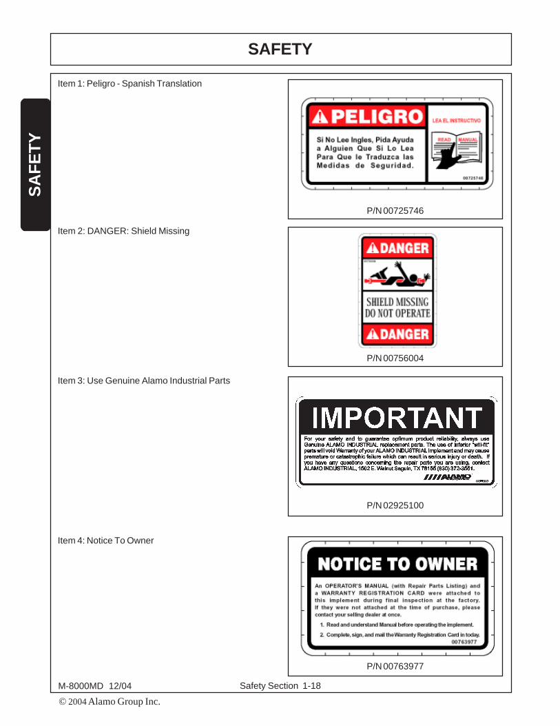
ITEM PART NO. QTY TYPE DECAL DESCRIPTION
1 00725746 1 PELIGRO Get Manual Translated2 00756004 1 DANGER Shield Missing3 02925100 1 IMPORTANT Genuine Alamo Industrial Parts4 00763977 1 INSTRUCT Notice To Owner5 00783744 1 WARNING Do Not Remove Guard6 00784039 1 DANGER Warning Multi-Hazard7 00784040 2 DANGER Rotating Snowblower Fan8 00784041 2 DANGER Thrown Objects9 00784043 1 DANGER Moving Parts10 00784044 2 DANGER Guard Missing11 00784045 2 DANGER Stay Back From Snowblower Intake12 00784054 1 WARNING No Smoking When Checking Battery Fluid13 00784055 1 WARNING No Smoking When Refueling Diesel14 00784056 1 WARNING Diesel Fuel Only15 00784057 2 WARNING Do Not Stick Hand In Rotaing Engine Fan16 00784058 1 INSTRUCT Lubrication Chart17 00784059 1 WARNING Remove Radiator Cap Slowly18 00784061 1 WARNING Do Not Let Spout Contact Electrical Power Lines19 00784062 1 INSTRUCT Type of Hydraulic Oil20 00784063 1 INSTRUCT Check Oil Level21 02962764 4 WARNING Pinch Points22 02962765 1 DANGER Multi-Hazard Pinch Points23 02965262 1 WARNING Hose Burst24 1438333 6 INSTRUCT Grease -10 Hrs25 1458392 2 REFLECT Red Reflector26 1458393 2 REFLECT Yellow Reflector27 02979545 1 NAME Alamo Industrial Logo28 00784060 1 WARNING Remove Key29 00784326 2 LOGO Great White30 N/A 1 SER PLT Great White Snowblower31 00024100 6 ---------------- Flatwasher32 10058000 3 ---------------- Bolt33 02959924 3 ---------------- Top Locknut34 00776031 1 ---------------- Canister, Operators Manual35 5040C 1 ---------------- Operators Manual
NOTE: Alamo Industrial supplies safety decals on this product to promote safe operation. Damage to the decalsmay occur while in shipping, use, or reconditioning. Alamo Industrial cares about the safety of its customers,operators, and bystanders, and will replace the safety decals on this product in the field, free of charge (Someshipping and handling charges may apply). Contact your Alamo Industrial dealer to order replacement decals.
Safety Section 1-18M-8000MD 12/04
SAFETY
© 2004 Alamo Group Inc.
SA
FE
TY
Item 1: Peligro - Spanish Translation
P/N 00725746
Item 2: DANGER: Shield Missing
P/N 00756004
Item 3: Use Genuine Alamo Industrial Parts
Item 4: Notice To Owner
P/N 02925100
P/N 00763977

Safety Section 1-19
SAFETY
© 2004Alamo Group Inc.
SA
FE
TY
M-8000MD 12/04
P/N 00783744
Item 5: Do Not Remove Guard
Item 6: WARNING: Multi Hazard
P/N 00784039
Item 7: DANGER: Avoid bodily injury fromrotating fans.
P/N 00784040
Item 8: DANGER: Keep Away - Thrownobject hazard. Stay away from discharge.
P/N 00784041

Safety Section 1-20M-8000MD 12/04
SAFETY
© 2004 Alamo Group Inc.
SA
FE
TY
Item 11: DANGER: Shut off Engine andwait until all motion has stopped beforeunclogging or servicing. Keep Hands, Feetand Clothing away from rotating fans.
P/N 00784045
Item 9: DANGER: Moving part hazard.Close and secure guards and shieldsbefore starting. Keep hands, feet, hair andclothing away from moving parts. Makesure that all moving parts have completelystopped before clearing blockage, debris orservicing. Do not approach, stand or climbon machine when it is operating.
P/N 00784043
Item 10: DANGER: Guard Missing - DoNot Operate.
P/N 00784044
Item 12: WARNING: Do not smoke whenchecking battery level. Fumes frombatteries are flammable and may explode.
P/N 00784054

Safety Section 1-21
SAFETY
© 2004Alamo Group Inc.
SA
FE
TY
M-8000MD 12/04
Item 13: WARNING: No Smoking whenrefueling diesel.
P/N 00784055
Item 14: WARNING: Diesel Fuel Only.
P/N 00784056
Item 15:DANGER: Do not stick hand intorotating engine fan.
P/N 00784057
Item 16: Lubrication RecommendationsChart
P/N 00784058

Safety Section 1-22M-8000MD 12/04
SAFETY
© 2004 Alamo Group Inc.
SA
FE
TY
Item 19:Type of Hydraulic Oil used.
P/N 00784062
Item 17: WARNING: Remove radiator capslowly. Contents are under pressure.
P/N 00784059
Item 18: WARNING: Keep Implement andChute at least 10 feet from electrical linesand pipelines to prevent accidental contactand possible serious injury or death.
P/N 00784061
Item 20: Check Oil Level
P/N 00784063

Safety Section 1-23
SAFETY
© 2004Alamo Group Inc.
SA
FE
TY
M-8000MD 12/04
Item 21: WARNING: Pinch Points
P/N 02962764
Item 22: DANGER: Moving machineryparts can pinch or crush or fall, which maycause injury or death.
P/N 02962765
Item 23: WARNING: Do Not Operate withOil Leaks. Inspect daily and replace wornhoses which can rupture suddenly andviolently resulting in serious bodily injury ordeath for scalding, fire, burn injury, or oilpenetration. Always use cardboard tocheck for oil leaks. If oil penetrates theskin, serious injury could result.
P/N 02965262
Item 24: Grease every 10 hours.
P/N 1438333

Safety Section 1-24M-8000MD 12/04
SAFETY
© 2004 Alamo Group Inc.
SA
FE
TY
Item 27: ALAMO INDUSTRIAL Name Decal
P/N 02979545
Item 31: WARNING: Remove engine keybefore preforming maintenance.
P/N 00784060
Item 25: Red Reflector
P/N 1458392
Item 26: Amber Reflector
P/N 1458393

Safety Section 1-25
SAFETY
© 2004Alamo Group Inc.
SA
FE
TY
M-8000MD 12/04
Item 32: NAME DECAL
P/N 00784326

Safety Section 1-26M-8000MD 12/04
SAFETY
© 2004 Alamo Group Inc.
SA
FE
TY
FEDERAL LAWS AND REGULATIONS
This section is intended to explain in broad terms the concept and effect of federal laws and regulationsconcerning employer and employee equipment operators. This section is not intended as a legal interpretation ofthe law and should not be considered as such.
Employer-Employee Operator RegulationsU.S. Public Law 91-596 (The Williams-Steiger Occupational and Health Act of 1970) OSHA
This Act Seeks:“...to assure so far as possible every working man and woman in the nation safe and healthfulworking conditions and to preserve our human resources...”
DUTIESSec. 5 (a) Each employer-(1) shall furnish to each of his employees employment and a place of employment which are freefrom recognized hazards that are causing or are likely to cause death or serious physical harm tohis employees;(2) shall comply with occupational safety and health standards promulgated under this Act.(b) Each employee shall comply with occupational safety and health standards and all rules,regulations and orders issued pursuant to this Act which are applicable to his own actionsand conduct.
OSHA Regulations:OSHA regulations state in part: “At the time of initial assignment and at least annually thereafter,the employer shall instruct every employee in the safe operation and servicing of all equipment withwhich the employee is, or will be involved.”
Employer Responsibilities:To ensure employee safety during Snowblowing operation, it is the employer’s responsibility to:
1. Train the employee in the proper and safe operation of the Snowblower.
2. Require that the employee to read and fully understand the Snowblower manuals.
3. Permit only qualified, properly licensed, and trained employees to operate the Snowblower.
4. Provide Personal Protective Equipment (PPE) to all operators, maintenance, and support workers of theSnowblower. This includes, but is not limited to, Safety Glasses, Safety Face shields, Safety toed shoes,Safety hard hat, Appropriate gloves, High-visual reflective vests, and Apron’s to provide adequate protectionfor the workers against inadvertent or accidental contact with hot surfaces, thrown objects, fluids, andchemicals used in the blowing processes and equipment.
5. Ensure that the operators, maintenance, and support workers wear the appropriate PPE when working on oraround the Snowblower.
6. Ensure that adequate traffic awareness and protection including signage, lighting, barriers, shielding, andwarnings are provided to protect the workers from inadvertent or accidental contact with vehicular traffic.
Safety Section 1-27
SAFETY
© 2004Alamo Group Inc.
SA
FE
TY
M-8000MD 12/04
7. Maintain the Snowblower in a safe operational condition and maintain all shields and guards on theequipment.
8. Ensure the Endloader is equipped with a functional seat belt and require that the operator securely fastenthe safety belt when operating the equipment.
9. Provide the required tools to maintain the Snowblower in a good safe working condition and provide thenecessary support devices to secure the equipment safely while performing repairs and service.
10. Require that the employee operator to stop blowing if bystanders or passerbys come within 200 feet.
Hazard Communication and MSDS information.OSHA requires the employer to inform the employee of the potential hazards associated with the chemicalsand materials that the employee may contact. This includes, but is not limited to, the diesel fuel andhydraulic oil. The Employer must provide annual training for the employee in Material Safety Data Sheets(MSDS), the location of the MSDS sheets, how to read and understand the MSDS information and the PPErequirements when using the chemicals.
Proper Disposal of Hazardous Waste MaterialsEPA regulations require the proper disposal of any hazardous chemicals and waste materials. This includes,but is not limited to, the diesel fuel, and hydraulic oil. Ensure that the employees and operators fullyunderstand and comply with their responsibilities for the handling and proper disposal of any hazardous wastematerials involved with the use of the Snowblower.


Introduction Section 2-1
INTRODUCTIONSECTION
© 2004 Alamo Group Inc.

Introduction Section 2-2
© 2004 Alamo Group Inc.
INTRODUCTIONIN
TRO
DU
CTI
ON
M-8000MD 12/04
The M8000MD Snowblower is strong, efficient, safe and easy to operate and provide you with years of trouble-freeservice. This snowblower works well in light, powdery or heavy, wet snow. A standard bolt-on replaceable taperedcutting edge is incorporated to loosen the snow on impact and guide it into the chopping system contributing toproductivity. Our snowblowers use a helical feeding and chopping system as the main part of the blowingoperation. This design allows the snow to be gathered, fed into the fan and discharged thought the spout in onemotion. The snow is never forced to change direction. You can blow the snow into a truck or free-cast withoutchanging the spout.
Built to last, the body of the M8000MD is a uniframe construction which produces a shell of superior strength. Thefans are driven by a high strength aircraft quality shaft that is coupled to a splined shear hub. Each fan issupported by bushings and bearings for cylindrical and thrust pressure. The M8000MD is designed with aminimum number of moving parts. The drivelines are enclosed in an oil bath reservoir. They can be easilyadjusted from outside of the reservoir without removing the covers.
All functions of the blower are operated by a control panel located inside the cab or with an optional wirelessremote control.
Safety is an important element of this snowblower. The snowblower's engine is mounted directly behind theblower unit. This gives the machines's operator a full range of sight for oncoming traffic and potential hazards inthe area. The weight of the snowblower is evenly distributed for a balanced machine.
The M8000MD is designed to attach to a commercial payloader used for snow removal. It fits front-end loaders,trucks or four-wheel-drive tractors. The snowblower easily attaches to a loader using a quick coupler, specified byCustomer.

Introduction Section 2-3
© 2004 Alamo Group Inc.
INTRODUCTIONIN
TRO
DU
CTI
ON
M-8000MD 12/04
ATTENTION OWNER/OPERATOR
BEFORE OPERATING THIS MACHINE:
1. Carefully read the Operator’s Manual, completely understand the Safety Messages and instructions, and know
how to operate correctly both the Power Unit and Snowblower.
2. Fill out the Warranty Card in full. Be sure to answer all questions, including the Serial Number of the Implement.
Mail within 30 days of delivery date of this implement.
NOTE: Warranties are honored only if completed “Owner Registration and Warranty” forms are received by Alamo
Industrial within thirty days of delivery of the Implement.
3. Record the Implement Model and Serial Numbers on the Warranty page at the front of the Operator’s Manual.
Keep this as part of the permanent maintenance file for the Implement.


Assembly Section 3-1
ASSEMBLYSECTION
© 2004 Alamo Group Inc.

Assembly Section 3-2M-8000MD 12/04
ASSEMBLYA
SS
EM
BLY
© 2004 Alamo Group Inc.
FIGURE 1 UNIT AS SHIPPED
SPOUT INSTALLATION
The Spout has been removed for shipping purposes. FIGURE 1 To install the spout to the main body of thesnowblower use an overhead hoist. Align bolt holes on spout with flange on base unit. Spout should face the sideof the machine. Securely tighten fasteners once all bolts have been installed. FIGURE 2
InstalledSpout
FIGURE 2 SPOUT INSTALLED
Assembly Section 3-3M-8000MD 12/04
ASSEMBLYA
SS
EM
BLY
© 2004 Alamo Group Inc.
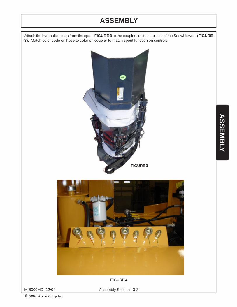
Attach the hydraulic hoses from the spout FIGURE 3 to the couplers on the top side of the Snowblower. (FIGURE3). Match color code on hose to color on coupler to match spout function on controls.
FIGURE 3
FIGURE 4

Assembly Section 3-4M-8000MD 12/04
ASSEMBLYA
SS
EM
BLY
© 2004 Alamo Group Inc.
CONNECTING HYDRAULIC HOSES TO SNOWBLOWER
When connecting snowblower, make sure the control cord is fastened securely to avoid damage. The hosescoming from the telescoping chute are color coded to match the functions on the control box. FIGURE 4
Control Box (FIGURE 6) is mounted by the dealer in the payloader cab. When using optional wireless remote(FIGURE 7) this control box is mounted on the machine and the remote pendent operates the functions.
ControlBox
Cab Control Box
OPTIONALRemote Control
FIGURE 5
FIGURE 6
FIGURE 7

Assembly Section 3-5M-8000MD 12/04
ASSEMBLYA
SS
EM
BLY
© 2004 Alamo Group Inc.
TURNING ON POWER UNIT
Unit is equipped with an Master Power Switch. This should be turned to the off position when blower is disconnectedfrom the power unit. Turn Master Power Switch to ON before coupling to power unit. Switch is located at the rearof the engine and can be accessed through to RH upper access panel. FIGURE 8
FIGURE 8
Power Switch


OPERATIONSECTION
© 2004 Alamo Group Inc.
Operation Section 4-1
OPERATION
Operation Section 4-2
OP
ER
AT
ION
© 2004 Alamo Group Inc.
M-8000MD 12/04
IMPORTANT: To avoid implement damage, retorque all bolts after the first 10 hours of operation.
OPERATOR REQUIREMENTS ............................................................................................................. 3-4
CONNECTING THE HYDRAULIC HOSES TO SNOWBLOWER ........................................................... 3-5
CONNECTING THE SNOWBLOWER TO UNIT ..................................................................................... 3-5
PRE-OPERATION INSPECTION AND SERVICE................................................................................... 3-6
FOREIGN DEBRIS HAZARDS .............................................................................................................. 3-8
OPERATING THE SNOWBLOWER ...................................................................................................... 3-9
STARTING THE SNOWBLOWER ....................................................................................................... 3-11
STARTING THE FAN ROTATION ......................................................................................................... 3-11
STORAGE .......................................................................................................................................... 3-12
TROUBLESHOOTING ......................................................................................................................... 3-12
The ALAMO INDUSTRIAL SNOWBLOWER is manufactured with quality material by skilled workers. This snowblower is designed for removing accumulations of snow from roadways and parking lots. The implement is equippedwith enough protective gear to maintain the objects being thrown from SNOWBLOWER to prevent injury tobystanders and others, however, no shielding is 100% accurate. All shields and guards must be maintained ingood operational condition.
It is the operator’s responsibility to be knowledgeable of all potential operating hazards and to take every reasonableprecaution to ensure oneself, others, animals, and property are not injured or damaged by the SNOWBLOWER,tractor, or a thrown object. Do not operate the implement if passersby, pets, livestock, or property are within 200feet of the unit.
This section of the Operator’s Manual is designed to familiarize, instruct, and educate safe and proper implementuse to the operator. Pictures contained in this section are intended to be used as a visual aid to assist inexplaining the operation of a SNOWBLOWER and are not necessarily of a SNOWBLOWER. Some pictures mayshow shields removed for picture clarity. NEVER OPERATE these implements without all shields in place and ingood operational condition. The operator must be familiar with the SNOWBLOWER operation and all associatedsafety practices before operating the SNOWBLOWER. Proper operation of the SNOWBLOWER, as detailed inthis manual, will help ensure years of safe and satisfactory use.
ALAMO INDUSTRIAL SNOW BLOWER OPERATION INSTRUCTIONS

OPERATIONO
PE
RA
TIO
N
Operation Section 4-3
© 2004 Alamo Group Inc.
M-8000MD 12/04
READ AND UNDERSTAND THE ENTIRE OPERATING INSTRUCTIONS AND SAFETY SECTION OF THISMANUAL AND THE TRACTOR MANUAL BEFORE ATTEMPTING TO USE THE POWER UNIT AND IMPLEMENT.If you do not understand any of the instructions, contact your nearest authorized dealer for a full explanation. Payclose attention to all safety signs and safety messages contained in this manual and those affixed to the Implementand power unit.
READ, UNDERSTAND, and FOLLOW the following Safety Messages. Seriousinjury or death may occur unless care is taken to follow the warnings andinstructions stated in the Safety Messages. Always use good common senseto avoid hazards. (SG-2)
DANGER!
Si no lee Ingles, pida ayuda a alguien que si lo lea para que le traduzcalas medias de seguridad. (SG-3)
PELIGRO!!LEA EL
INSTRUCTIVO!

OPERATION
Operation Section 4-4
OP
ER
AT
ION
© 2004 Alamo Group Inc.
M-8000MD 12/04
OPERATOR REQUIREMENTS
Safe operation of the snow blower is the responsibility of a qualified operator. A qualified operator has read andunderstands all Operator’s Manuals and is experienced with snow blower operations and all associated safetypractices. In addition to the safety messages contained in this manual, safety message decals are affixed to thesnow blower and tractor. If any part of the operation and safe use of the snow blower are not completely understood,consult an authorized dealer for a full explanation.
Safe operation requires that the operator wear approved Personal Protective Equipment (PPE) for the job conditionswhile connecting, operating, servicing and repairing the snow blower. PPE is designed to provide operator protectionfrom bodily injury and includes the following:
Personal Protective Equipment (PPE)
Protective eye glasses, goggles, or face shieldHard hatSteel toed safety footwearGlovesHearing protectionClose fitting clothingRespirator or filter mask
NEVER use drugs or alcohol immediately before or while operatingthe Tractor and Implement. Drugs and alcohol will affect anoperator’s alertness and coordination and therefore affect theoperator’s ability to operate the Equipment safely. Beforeoperating the Tractor or Implement, an operator on prescriptionor over-the-counter medication must consult a medicalprofessional regarding any side effects of the medication thatwould hinder their ability to operate the Equipment safely.NEVER knowingly allow anyone to operate this Equipment whentheir alertness or coordination is impaired. Serious injury ordeath to the operator or others could result if the operator isunder the influence of drugs or alcohol. (SG-27)
DANGER!

OPERATIONO
PE
RA
TIO
N
Operation Section 4-5
© 2004 Alamo Group Inc.
M-8000MD 12/04
CONNECTING THE HYDRAULIC HOSES TO SNOWBLOWER
When connecting snowblower, make sure the control cord is fastened securely to avoid damage.
ControlBox
Cab Control Box
OPTIONALRemote Control
FIGURE 1
FIGURE 2
FIGURE 3

OPERATION
Operation Section 4-6
OP
ER
AT
ION
© 2004 Alamo Group Inc.
M-8000MD 12/04
Snow Blower Pre-Operation Inspection/ServiceBefore each season of use, a complete inspection andservice is required to ensure the implement is in a goodand safe working condition. Damaged and/or brokenparts should be repaired and/or replaced immediately.To ensure the implement is ready for operation, conductthe following.
Ensure that the Manual Holder secured to theImplement with the Operator’s Manual inside.Ensure all decals are in place and legible. Replacemissing, worn, and non-legible decals.
NOTE: The snow blower Operator’s Manual and affixedDecals contain important instructions on the safe andproper use of the snow blower. Maintain these importantsafety features on the snow blower in good conditionto ensure the information is available to the operator atall times.
CONNECTING THE SNOWBLOWER TO UNIT
To mount on a front-end loader, the unit easily attaches by using a quick coupler. Ensure the coupler is locked inplace before raising the boom.
FIGURE 4
FIGURE 5
OPERATIONO
PE
RA
TIO
N
Operation Section 4-7
© 2004 Alamo Group Inc.
M-8000MD 12/04
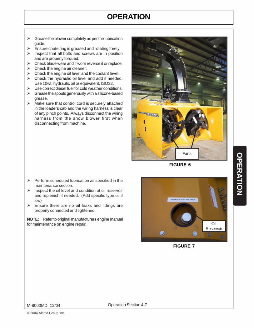
Perform scheduled lubrication as specified in themaintenance section.Inspect the oil level and condition of oil reservoirand replenish if needed. (Add specific type oil iflow)Ensure there are no oil leaks and fittings areproperly connected and tightened.
OilReservoir
Grease the blower completely as per the lubricationguide.Ensure chute ring is greased and rotating freelyInspect that all bolts and screws are in positionand are properly torqued.Check blade wear and if worn reverse it or replace.Check the engine air cleaner.Check the engine oil level and the coolant level.Check the hydraulic oil level and add if needed.Use 10wt. hydraulic oil or equivalent, ISO32.Use correct diesel fuel for cold weather conditions.Grease the spouts generously with a silicone-basedgrease.Make sure that control cord is securely attachedin the loaders cab and the wiring harness is clearof any pinch points. Always disconnect the wiringharness from the snow blower first whendisconnecting from machine.
Fans
FIGURE 6
FIGURE 7
NOTE: Refer to original manufacturers engine manualfor maintenance on engine repair.

OPERATION
Operation Section 4-8
OP
ER
AT
ION
© 2004 Alamo Group Inc.
M-8000MD 12/04
DANGER! Do not operate this Equipment with hydraulic oil leaking. Oil isexpensive and its presence could present a hazard. Do not check forleaks with your hand! Use a piece of heavy paper or cardboard. High-pressure oil streams from breaks in the line could penetrate the skinand cause tissue damage including gangrene. If oil does penetrate theskin, have the injury treated immediately by a physician knowledgeableand skilled in this procedure. (SG-15)
DANGER! Never work under the Implement, the framework, or any lifted componentunless the Implement is securely supported or blocked up to preventsudden or inadvertent falling which could cause serious injury or evendeath. (SG-14)
Check Chain Case Oil on RH side of machine.Remove plug shown in Figure. Oil level should beat level of grove on Dip Stick. Add oil if required.Use Chevron Vistec ISO68 or Mobil Vactra #2.
There are three separate oil systems on theM8000MD, Excluding the engine.1. Hydraulic Oil Level - Use ISO32 Hydraulic Oil2. Drive Chain Case - Recommended: Mobil VactraNo. 2 or Chevon Wayoil Vistac ISO68 - both ofthese recommended lubricants contain a tackingagent which improves the lubricants ability to adhereto components, preventing corrosion. FIGURE 8
Gearbox Lubricant - Recommended LubricantISO32 hydraulic oil. The gearbox oil is circulatedthrough an oil cooler and requires a light weightoil. FIGURE 9
FIGURE 8
FIGURE 9
Crank Case Dipstick

OPERATIONO
PE
RA
TIO
N
Operation Section 4-9
© 2004 Alamo Group Inc.
M-8000MD 12/04
WARNING! Blow snow at the speed that you can safely operate and control theTractor and Snow Blower. Safe speed depends on terrain and snowconditions. Normal ground speed range is from 0 to 5 mph. Use slowspeeds when operating on or near steep slopes, ditches, drop-offs,overhead obstructions, power lines, or when debris and foreign objectsare to be avoided. (SSB-4)
If you hit a solid object or foreign debris stop the Snow Blower at once. Wait for all rotating motion to stop, thenraise the blower off the object. Inspect the area and mark the location of the debris. Inspect the condition of theimplement and make any needed repairs immediately. Make sure the auger is not damaged before resumingoperation.
WARNING! Be sure you have adequate knowledge of the property you will be workingon. Take time to make yourself aware of any area underground lines orcables. Contact with buried lines or cable could result in serious injuryor death. (STL-1)
DANGER! There are obvious and hidden potential hazards in the operation of thisSnow Blower. REMEMBER! This machine is often operated in deepsnow where vision is reduced. The fan blades of this Snow Blower canthrow objects for great distances Serious injury or even death mayoccur unless care is taken to insure the safety of the operator,bystanders, or passersby in the area. Do not operate this machinewith anyone in the immediate area. Stop Snow Blowing if anyone iswithin 200 feet of Snow Blower. (SSB-11)
Foreign Debris Hazards
Remove all foreign objects and debris. If objects aretoo big to remove, mark them clearly and be sure toprevent the implement from contacting them.
FIGURE 10
OPERATION
Operation Section 4-10
OP
ER
AT
ION
© 2004 Alamo Group Inc.
M-8000MD 12/04
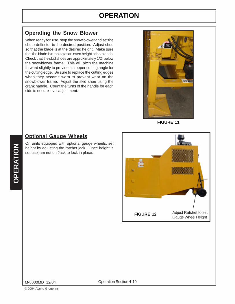
Operating the Snow BlowerWhen ready for use, stop the snow blower and set thechute deflector to the desired position. Adjust shoeso that the blade is at the desired height. Make surethat the blade is running at an even height at both ends.Check that the skid shoes are approximately 1/2” belowthe snowblower frame. This will pitch the machineforward slightly to provide a steeper cutting angle forthe cutting edge. Be sure to replace the cutting edgeswhen they become worn to prevent wear on thesnowblower frame. Adjust the skid shoe using thecrank handle. Count the turns of the handle for eachside to ensure level adjustment.
FIGURE 11
FIGURE 12
Optional Gauge WheelsOn units equipped with optional gauge wheels, setheight by adjusting the ratchet jack. Once height isset use jam nut on Jack to lock in place.
Adjust Ratchet to setGauge Wheel Height

OPERATIONO
PE
RA
TIO
N
Operation Section 4-11
© 2004 Alamo Group Inc.
M-8000MD 12/04
See Maintenance Section.Remove lid to greaseInternal Bearings
CAUTION! If removing snow from other than paved or hard surfaced areas, move deflector to thelow position to minimize the distance that gravel or foreign material is ejected.
DANGER! DO NOT operate this Implement on a Power Unit that is not properly maintained.Should a mechanical or Power Unit control failure occur while operating,immediately shut down the Power Unit and perform repairs before resumingoperation. Serious injury and possible death could occur from not maintainingthis Implement and Power Unit in good operating condition. (SPU-38)
WARNING! Only operate the snow blower in conditions were you have clear visibility indaylight or with adequate artificial lighting. Never snow blow in darkness or inconditions where you cannot clearly see at least 100 yards in front and to thesides of the Power Unit and Snow Blower. Make sure that you can clearly seeand identify passersby, steep slopes, ditches, drop-offs, overhead obstructions,power lines, debris and foreign objects. If you are unable to clearly see thesetypes of items, discontinue snow blowing. (SSB-1)
FIGURE 13
Before operating the snow blower recheck that allfasteners, nuts, bolts, screws and cotter pins are inplace and all bolts are torqued to specification.
Check Roller chains for tightness and adjust the idlersprockets accordingly. ALWAYS keep roller chain tight.
See Cummins Engine Manual for instructions relatedto QSB220 Powerunit.
OPERATION
Operation Section 4-12
OP
ER
AT
ION
© 2004 Alamo Group Inc.
M-8000MD 12/04
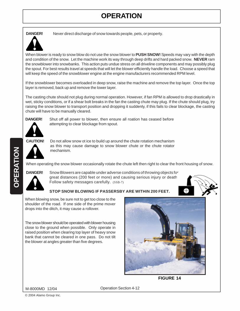
When blowing snow, be sure not to get too close to theshoulder of the road. If one side of the prime moverdrops into the ditch, it may cause a rollover.
The snow blower should be operated with blower housingclose to the ground when possible. Only operate inraised position when clearing top layer of heavy snowbank that cannot be cleared in one pass. Do not tiltthe blower at angles greater than five degrees.
DANGER! Snow Blowers are capable under adverse conditions of throwing objects forgreat distances (200 feet or more) and causing serious injury or death.Follow safety messages carefully. (SSB-7)
STOP SNOW BLOWING IF PASSERSBY ARE WITHIN 200 FEET.
When blower is ready to snow blow do not use the snow blower to PUSH SNOW! Speeds may vary with the depthand condition of the snow. Let the machine work its way through deep drifts and hard packed snow. NEVER ramthe snowblower into snowbanks. This action puts undue stress on all driveline components and may possibly plugthe spout. For best results travel at speeds that will let the blower efficiently handle the load. Choose a speed thatwill keep the speed of the snowblower engine at the engine manufacturers recommended RPM level.
If the snowblower becomes overloaded in deep snow, raise the machine and remove the top layer. Once the toplayer is removed, back up and remove the lower layer.
The casting chute should not plug during normal operation. However, if fan RPM is allowed to drop drastically inwet, sticky conditions, or if a shear bolt breaks in the fan the casting chute may plug. If the chute should plug, tryraising the snow blower to transport position and dropping it suddenly, if this fails to clear blockage, the castingchute will have to be manually cleared.
CAUTION! Do not allow snow ot ice to build up around the chute rotation mechanismas this may cause damage to snow blower chute or the chute rotatormechanism.
When operating the snow blower occasionally rotate the chute left then right to clear the front housing of snow.
DANGER! Never direct discharge of snow towards people, pets, or property.
FIGURE 14
DANGER! Shut off all power to blower, then ensure all roation has ceased beforeattempting to clear blockage from spout.

OPERATIONO
PE
RA
TIO
N
Operation Section 4-13
© 2004 Alamo Group Inc.
M-8000MD 12/04
Starting the Snow Blower
Make sure that the clutch is disengaged.
Make sure that the blower is securely attached to theprime mover. Failure to do so can result in bodily injuryor damage to the machine.
Start engine only with throttle set to idle.
Slow the engine down to an idle before engaging theclutch by pushing the green, “Clutch On” button. Neverengage or disengage the clutch at higher speeds orserious damage to the power train could result. Theclutch push button is illuminated.
To disengage clutch set throttle to slow and push clutchoff switch.
On blowers equipped with a wireless remote engageclutch by depressing “Clutch On” button. To turn offclutch press “Clutch Off” button.
Before starting into a snowdrift, speed up the engineto the maximum RPM (approx. 2500 RPM) by pushingthe throttle up. Continue into the snow approximately1/3 to 1/2 MPH or whatever speed the engine will allowthe blower to travel.
When shutting down the blower, throttle down thesnowblower to an idle and disengage the clutch beforeshutting down the blower engine.
Never have the snowblower clutch engaged and runningwhen the operator is not sitting in the operators seaton the power unit.
To Start Fan Rotation
To Start
CONTROL BOX
FIGURE 15
DANGER! Never use ether (Starting Fluid) as Engineis equipped with a grid heater on the intakemanifold. Use of ether could result in anexplosion and possibly cause injury.
Use key to start engine. On units equipped with wirelessremote turn key on control box to on position power onpendent. Press shift key and start button to startengine. Wait for engine to warm up before engagingfan clutch.

OPERATION
Operation Section 4-14
OP
ER
AT
ION
© 2004 Alamo Group Inc.
M-8000MD 12/04
REMOTE CONTOL FUNCTION GUIDE(Optional Feature)
< SHIFT >START ENGINE
CLUTCHENGAGE
CLUTCHDISENGAGE
< SHIFT >SPOUT
UP
RPMUP
ROTATE SPOUTLEFT
PRIMARYFLIPPER UP
SECONDARYFLIPPER UP
RPMDOWN
< SHIFT >SPOUTDOWN
ROTATE SPOUTRIGHT
PRIMARYFLIPPER DOWN
SECONDARYFLIPPER DOWN
POWER ON(Also used as a Shift Button)
POWER OFF / SHUT DOWN (ESTOP)
Turn on key on Snowblower Control Box to power up the remote control. To power up Engine, depress shift andpower button. Wait for engine to warm up before raising the RPM or engaging clutch.
ENGINE STARTThe Engine Start is a momentary output that can only be activated once. After the output has been activated theE-Stop must be pressed and the link reestablished before it can be activated again.
SPOUT ACTIVATIONFor spout activation momentarily press button as outlined above.
FIGURE 16

OPERATIONO
PE
RA
TIO
N
Operation Section 4-15
© 2004 Alamo Group Inc.
M-8000MD 12/04
Properly preparing and storing the snow blower at the end of the season is critical to maintaining its appearanceand to help ensure years of dependable service. The following are suggested storage procedures:
1. Thoroughly clean all debris off the implement toprevent damage from rotting grass and standingwater.
2. Lubricate all implements points and fill gearbox oillevels as detailed in the maintenance section.
3. Tighten all bolts and pins to the recommendedtorque.
4. Check the implement for worn and damaged parts.Perform repairs and make replacementsimmediately so that the implement will be readyfor use at the start of the next season.
5. Store the implement in a clean, dry place with theimplement resting securely on blocks or at groundlevel.
6. Keep the drivelines yokes or hydraulic hoses fromsitting in water, dirt and other contaminants.
7. Use spray touch-up enamel where necessary toprevent rust and maintain the appearance of theimplement.
8. Shut off Master Power Switch.
SNOW BLOWER STORAGE
FIGURE 18MASTER POWER SWITCH
FIGURE 17

OPERATION
Operation Section 4-16
OP
ER
AT
ION
© 2004 Alamo Group Inc.
M-8000MD 12/04
TROUBLE SHOOTING GUIDE (SNOW BLOWER)
POSSIBLE CAUSE
Gear Ratio too highon Prime Mover
Blade scraping ground
Ballast or Prime Mover
Loose bolts
Worn universal jointsbearings
Worn bearings
Check hydraulic pressure
Driveline Shear BoltBroken
POSSIBLE REMEDY
Gear down Prime Mover
Increase unit height
Install chains
Tighten bolts
See your dealer
See your dealer
Install check valve asshown on parts page
Replace Shear Bolt
TROUBLE
Excessive power requiredto operate snow blower
Wheel slippage
Excessive Mechanicalnoise
Does not throw snow
Fan Does not Work
CLUTCH HYDRAULIC PRESSURE
Hydraulic Clutch SystemPressure Gauge
FIGURE 19
© 2004 Alamo Group Inc.
MAINTENANCESECTION
Maintenance Section 5-1

MAINTENANCE
Maintenance Section 5-2
© 2004 Alamo Group Inc.
MA
INT
EN
AN
CE
M-8000MD 12/04
General Maintenance ScheduleCheck the engine air cleaner regularly. (FIGURE 1)Check the engine oil level and the coolant level requently as per the engine manual.Check the hydraulic oil level regularly and add when needed. Use a 10 wt. hydrualic oil or equivalent.Use the correct diesel fuel for cold weather conditions.Check that the skid shoes are approximately 1/2" below the snowblower frame. Be sure to replace the cuttingedges when they become worn to prevent wearing into the snowblower frame.
Chute
Apply grease to the exposed face of the chute ring.
Check Air CleanerService Indicator
Drive Assembly
The oil bath housing for the drive assembly containsapproximately 15 gallons of standard ISO 68 oil - MobilVactra 2 or Chevron Vistac ISO 68 (enough oil to coverthe bottom 2" of the drive sprockets). This oil bathassures long sprocket and chain life while dissipatingheat caused by moving parts. Periodically check theoil level and replenish as necessary. Check rollerchains for tightness and adjust the idler sprocketsaccordingly. ALWAYS keep the roller chain tight.See Section 5-4 for procedure.
Use ISO68 oil or equivalent foroil bath. (15 gallon capacity)
Nuts And Bolts
1.Check all nuts and bolts for correct torque after the first 5 hours of operation then yearly.
IMPORTANT: Each fan is protected by a shear bolt located at the front of the fan shaft. FIGURE 3. Replace asneeded. Shear bolts should not be over tightened, as this may cause unpredictable shearing action.
FIGURE 1
FIGURE 2
DRIVE ASSEMBLY

MAINTENANCE
Maintenance Section 5-3
© 2004 Alamo Group Inc.
MA
INTE
NA
NC
E
M-8000MD 12/04
OIL RESERVOIR
Do not grease Bearings the first yearof operation. Grease the second yearand thereafter. Give each Bearingtwo pumps with a hand operatedgrease gun every season.
Use SAE ISO68 oil or equivalentfor oil bath. (15 gallon capacity)
Remove lid to grease InternalPillow Block Bearing.
WARNING! Never attempt to lubricate, adjust, or remove material from the Implementwhile it is in motion or while tractor engine is running. Make sure thetractor engine is off before working on the implement. (SG-20)
WARNING! Relieve hydraulic pressure prior to doing any maintenance or repair workon the Implement. Place the Implement on the ground or securelyblocked up, disengage the PTO, and turn off the tractor engine. Push andpull the Remote Cylinder lever in and out several times prior to starting anymaintenance or repair work. (S3PT-9)
Shear Bolt
1. IMPORTANT: If a shear bolt breaks duringoperation immediately shut down the Power Unit andwait for all rotation to cease before replacing the shearbolt.
2. The shear bolts used on this snow blower aremachined with a shear groove for this specificapplication. Use only Part No. 00783322. Alwaysstock spare shear bolts in case you encounter toughconditions. The machine is shipped with 8 sparebolts.
IMPORTANT: Tighten nut only enough to draw theshear plates together. Do not over tighten nut.Occasionally grease shear mechanism inside andtoward front of fan and toward rear of fan. Fan isequipped with taper bearing for shear rotation.
IMPORTANT: Replacement of the shear bolt withone of any other grade or size will be consideredan unauthorized modification and the warrantywill be void.
Shear BoltDouble Nut Shear Bolt to
prevent loosening.
Never install twoshear bolts.Second holeprovided as
alternate if firsthole is damaged.
FIGURE 3
FIGURE 4

MAINTENANCE
Maintenance Section 5-4
© 2004 Alamo Group Inc.
MA
INT
EN
AN
CE
M-8000MD 12/04
Follow these simple steps to tighten the main drive chain which runs in the oil bath reservoir. Remember: You donot need to remove the reservoir cover to tighten the drive chain.
1. Locate the take-up bolt. This bolt is found on the right side of the blower, through the large hole in the sideshield. Inside the shield you will find a locking channel up, exposing the idler take-up bolt.
2. Using a torque wrench, tighten the take-up bolt by turning it clockwise to 9 ft. lbs. of torque. Turn bolt headclockwise until the bolt head flats are parallel with the locking channel to slip back over the bolt head.
NOTE: Be sure to tighten the chain by following these instructions. The chain should be tightened after the first10 hours of operation and ever 100 hours thereafter.
CHAIN TENSIONING INSTRUCTIONS
STORAGE
Wash any dirt or salt off the snow blower.
Smear grease over any exposed hydraulic cylinder rods.
Locking ChannelFIGURE 6
Tensioner BoltFIGURE 7
FIGURE 5

MAINTENANCE
Maintenance Section 5-5
© 2004 Alamo Group Inc.
MA
INTE
NA
NC
E
M-8000MD 12/04
MAINTENANCETO PREFORM Weekly
Daily(8-10 Hrs.) 100 Hrs.
150 Hrs.or
1 Month
500 Hrs.or
6 Months
2000 Hrs.or
1 Year
Engine Oil Level
Engine Coolant Level
Engine Air Cleaner
Hydraulic Oil Level
Check Engine Radiator
Check Hydraulic Oil Cooler
Check Hydraulic Oil Temp.
Clutch: Cross Shaft
Fan Shaft Assembly Bearings
Oil All Chain Couplings
Engine Oil Change
Engine Oil Filters
Clutch: Throw-Out Bearings
Gearbox (Mobil SHC 75W-90)
Grease All Bearings
Hydraulic Filters Replacement
Engine Fuel Filters
Spout Bearings
Engine Coolant Change
Hyd. Oil Change (ISO 32 Hyd. Oil)
Fan Shaft Bearings
Engine Water Filters (if applicable)
Oil Bath (ISO68 Bar Chain Oil)
X
X
X
X
X
X
X
X
X
X
X
X
X
X
X
X
X
X
X
X
X
X
X
* NOTE: On a new engine, change oil and oil filter at 50 Hrs. and every 100 Hrs. thereafter.
NOTE: Hydraulic oil filter should be changed at 50 Hrs. and every 500 Hrs. thereafter.
Schedule for checking Components, Fluid Levels, Greasing and Maintaining Blowers.


TRANSFLUIDCLUTCH ASSEMBLY
TRANSFLUID Section 6-1
© 2004Alamo Group Inc.

TRANSFLUID
TRANSFLUID Section 6-2
© 2004 Alamo Group Inc.
M-8000MD 12/04
OM
NE
X

TRANSFLUID
TRANSFLUID Section 6-3
© 2004 Alamo Group Inc.
M-8000MD 12/04
OM
NE
X

TRANSFLUID
TRANSFLUID Section 6-4
© 2004 Alamo Group Inc.
M-8000MD 12/04
OM
NE
X
INSTALLATION (see FIG.2 and drawing at page 7)
1 Mount driving ring 31 onto engine flywheel.2 Mount the pilot bearing 41 (greased for life), onto shaft 5 of the
power take off.3 Mount the housing 1 onto engine flywheel housing. Position
power take off, paying attention to alignment between shaft 5and pilot bearing 41, with its flywheel seat and driving ring 31mounted onto flywheel. In order to align between housing 1and flywheel housing, use 3 threaded rods with adequatelengths, mounted 120° apart onto flywheel housing.
4 Through opening on housing 1, guide the teeth of the plates 23into the driving ring 31. External housing should be orientatedto get the opening on vertical line. Tighten screws of externalSAE flange.
5 All power take-offs are supplied already greased. Only forthe HFF 211-L, after the first 100 hours of operation thegrease level should be checked. Removing the overflow plug40, insert a screw driver into the cavity and check if thegrease is present. If necessary add grease (see BEARINGGREASE table page 6) through the greaser 11. For nextmaintenance cycle see Maintenance table page 3.CAUTION: Do Not Overgrease, through greaser 11, bearingcavity. It might cause the main bearing to overheat and greaseto exit from seals.
6 Hit the shaft on the end, with a rubber mallet, to relieve anypre-loading against the bearings that may result due to theresistance of pilot bearing when being pressed into theflywheel.
7 For HFF 211-L mount a support plate onto spacer 36, toassure that the overhung load on the engine flywheel housingis relived and any misalignment caused by this overhang isrelived, the support plate should be shimmed following theprocedure:A-attach dial indicator to engine block (see FIG. 2 page 1) withindicator anvil resting on bearing carrier at opposite directionof belts.B-set indicator to zero.C-tension the beltsD-shim under support plate to return indicator to zero.
8 Rotary union 14 is supplied separately. Before installation,grease O-Ring mounted on rotary union. Fix lockwasher 15tightening screws 16.
9 Connect rotary union 14 through a suitable flexible hose.10 Install a three way valve for oil pressure feeding. The
operating oil pressure must be 25 bar (max 30 bar).CAUTION: With the clutch disengaged the residual pressureshould be 0 bar. For pressure over 0 bar contactTRANSFLUID.
11 At first start up, rotate engine by hand in insure there are nointerferences. After, run power take off with engaged clutchand engine at half of max speed for not less than 10 minutes.CAUTION: In case of a long start up period, mor than fourseconds, or engine kill, or clutch overheating, caused by asizable mass and driven inertial load, a BUMPING-IN sequencemay be used. Engage the power take off for no more than 3 or4 times lasting one second each.
INSTALLATION (see FIG.2 and drawing at page 7)
1 Every 500 working hours add 13g (14 cc) of grease (seeBEARING GREASE table page 6) through the greaser 11.
2 After 3000 working hours it is recommended to purge theold grease. The old grease should be replaced if the unithas not been used for more than 6 months. Each bearing,not the bearing cavity, should be packed withapproximately 19 g (20 cc) of new grease. Grease shouldthen be added through the greaser 11. To refill, to theproper level (approximately 50%), a completely emptybearing cavity will require approximately 56 g (60 cc) ofgrease.
3 In case of taper roll bearings replacement, adjust asfollows:A - Refill grease inside the bearings and the bearings cavityas described above at point 2.B - Tighten threaded ring 8, turning manually the shaft 5,until some resistance of shaft rotation occurs.C - Back off threaded ring, 1 - 2 notches.D - With a rubber mallet (non metallic), hit the shaft on theend, to seat bearing outer race against threaded ring. Thisshould give, approximately, the end play of 0.15 - 0.25 mm.E - Lock threaded ring 8 through lock bearing retainer 12and screw 10.F - See item 6 and 11 on INSTALLATION table page 2.
4 It is advisable, every 4000 working hours, to check bearingcondition.
5 Check driving plate condition once a year.
MAINTENANCE for HFO-HFF 211-L
1 After the first 100 hours of operation the grease levelshould be checked as described on INSTALLATION table atpoint 5 page 2.
2 Every 500 working hours add 19g (20 cc) of grease (seeBEARING GREASE page 6) through the greaser 11.Remove the overflow plug 40 to insure that the grease isnot overfilled.
3 After 3000 working hours it is recommended to purge theold grease. The old grease should be replace if the unit hasnot been used for more than 6 months. The bearing, not thebearing cavity, should be packed with approximately 49g(52 cc) of new grease and the cover remounted. Removethe overflow plug 40 to control for overfilling. Greaseshould then be added through the greaser 11. To emptybearing cavity will require approximately 89g (94 cc) ofgrease. 100 hours of operation after purging, the greaselevel should be checked as described on INSTALLATIONtable at point 5 page 2.
4 It is advisable, every 4000 working hours, to check bearingcondition.
5 Check condition of driving plates once a year.
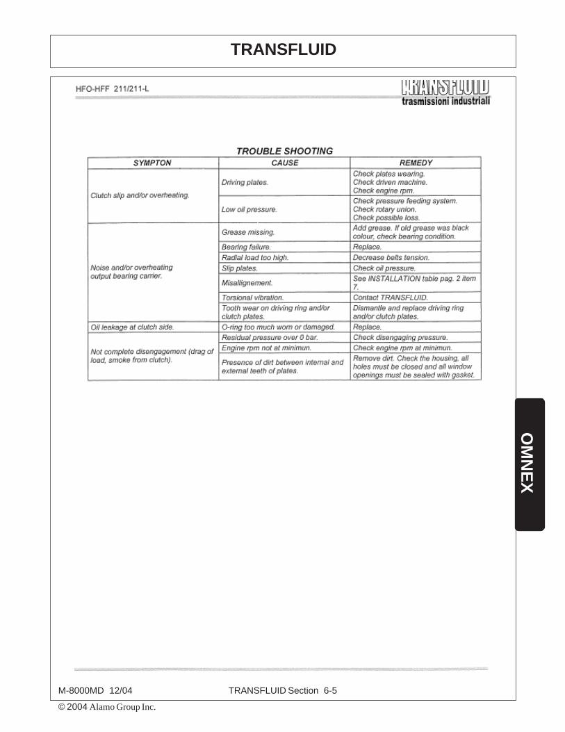
TRANSFLUID
TRANSFLUID Section 6-5
© 2004 Alamo Group Inc.
M-8000MD 12/04
OM
NE
X

TRANSFLUID
TRANSFLUID Section 6-6
© 2004 Alamo Group Inc.
M-8000MD 12/04
OM
NE
X

TRANSFLUID
TRANSFLUID Section 6-7
© 2004 Alamo Group Inc.
M-8000MD 12/04
OM
NE
X

TRANSFLUID
TRANSFLUID Section 6-8
© 2004 Alamo Group Inc.
M-8000MD 12/04
OM
NE
X

OMNEXOPTIONAL EQUIPMENT
OMNEX Section 7-1
© 2004Alamo Group Inc.

OMNEX (OPTIONAL EQUIPMENT)
OMNEX Section 7-2
© 2004 Alamo Group Inc.
M-8000MD 12/04
OM
NE
X
REMOTE CONTOL FUNCTION GUIDE(Optional Feature)
< SHIFT >START ENGINE
CLUTCHENGAGE
CLUTCHDISENGAGE
< SHIFT >SPOUT
UP
RPMUP
ROTATE SPOUTLEFT
PRIMARYFLIPPER UP
SECONDARYFLIPPER UP
RPMDOWN
< SHIFT >SPOUTDOWN
ROTATE SPOUTRIGHT
PRIMARYFLIPPER DOWN
SECONDARYFLIPPER DOWN
POWER ON(Also used as a Shift Button)
POWER OFF / SHUT DOWN(E Stop)

OMNEX (OPTIONAL EQUIPMENT)
OMNEX Section 7-3
© 2004 Alamo Group Inc.
M-8000MD 12/04
OM
NE
X
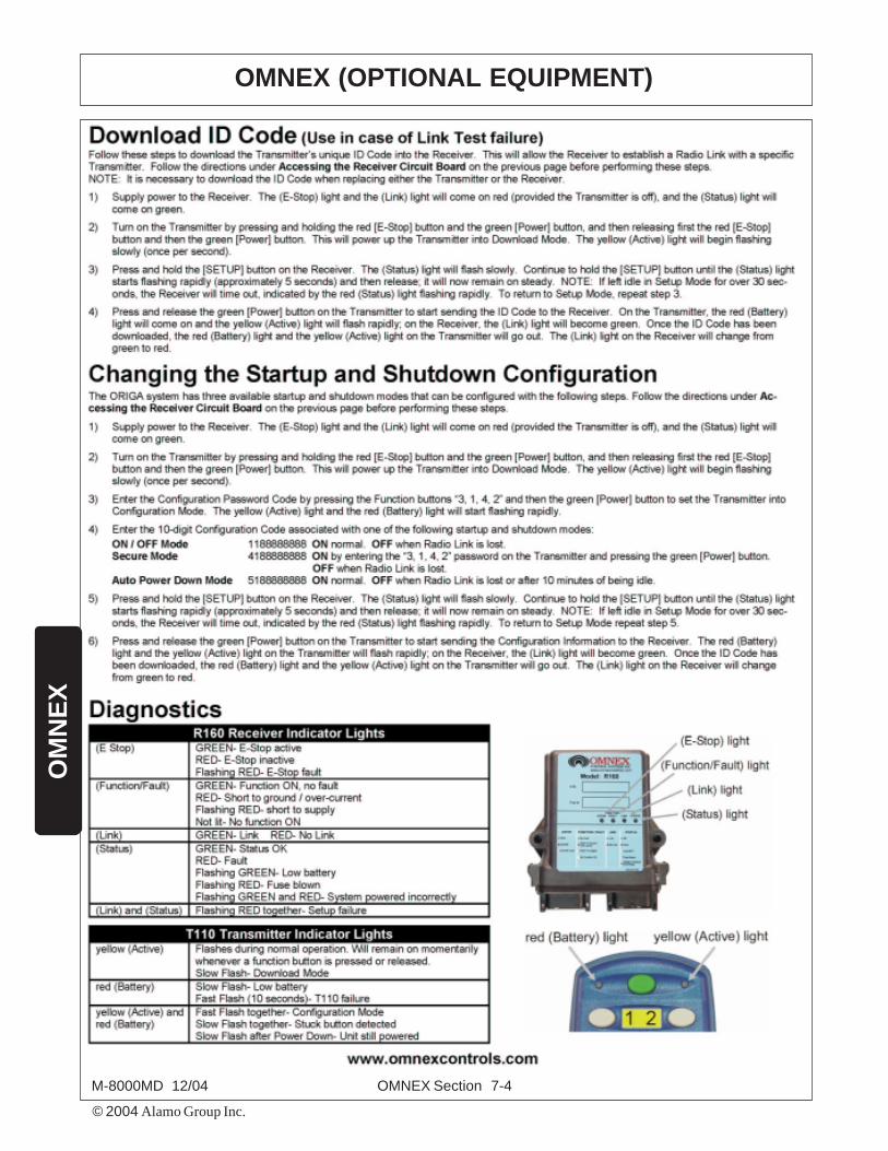
OMNEX (OPTIONAL EQUIPMENT)
OMNEX Section 7-4
© 2004 Alamo Group Inc.
M-8000MD 12/04
OM
NE
X

OMNEX (OPTIONAL EQUIPMENT)
OMNEX Section 7-5
© 2004 Alamo Group Inc.
M-8000MD 12/04
OM
NE
X

OMNEX (OPTIONAL EQUIPMENT)
OMNEX Section 7-6
© 2004 Alamo Group Inc.
M-8000MD 12/04
OM
NE
X

OMNEX (OPTIONAL EQUIPMENT)
OMNEX Section 7-7
© 2004 Alamo Group Inc.
M-8000MD 12/04
OM
NE
X

OMNEX (OPTIONAL EQUIPMENT)
OMNEX Section 7-8
© 2004 Alamo Group Inc.
M-8000MD 12/04
OM
NE
X

LIMITED WARRANTY
1. LIMITED WARRANTIES1.01.Alamo Industrial warrants for one year from the purchase date to the original non-commercial, governmental, or
municipal purchaser (“Purchaser”) and warrants for six months to the original commercial or industrial purchaser(“Purchaser”) that the goods purchased are free from defects in material or workmanship.
1.02.Manufacturer will replace for the Purchaser any part or parts found, upon examination at one of its factories, to bedefective under normal use and service due to defects in material or workmanship.
1.03.This limited warranty does not apply to any part of the goods which has been subjected to improper or abnormal use,negligence, alteration, modification, or accident, damaged due to lack of maintenance or use of wrong fuel, oil, orlubricants, or which has served its normal life. This limited warranty does not apply to any part of any internalcombustion engine, or expendable items such as blades, shields, guards, or pneumatic tires except as specifically foundin your Operator’s Manual.
1.04.Except as provided herein, no employee, agent, Dealer, or other person is authorized to give any warranties of anynature on behalf of Manufacturer.
2. REMEDIES AND PROCEDURES.2.01.This limited warranty is not effective unless the Purchaser returns the Registration and Warranty Form to Manufacturer
within 30 days of purchase.2.02.Purchaser claims must be made in writing to the Authorized Dealer (“Dealer”) from whom Purchaser purchased the
goods or an approved Authorized Dealer (“Dealer”) within 30 days after Purchaser learns of the facts on which theclaim is based.
2.03.Purchaser is responsible for returning the goods in question to the Dealer.2.04.If after examining the goods and/or parts in question, Manufacturer finds them to be defective under normal use and
service due to defects in material or workmanship, Manufacturer will:(a) Repair or replace the defective goods or part(s) or(b) Reimburse Purchaser for the cost of the part(s) and reasonable labor charges (as determined by Manufacturer)
if Purchaser paid for the repair and/or replacement prior to the final determination of applicability of the warrantyby Manufacturer.
The choice of remedy shall belong to Manufacturer.2.05.Purchaser is responsible for any labor charges exceeding a reasonable amount as determined by Manufacturer and
for returning the goods to the Dealer, whether or not the claim is approved. Purchaser is responsible for the trans-portation cost for the goods or part(s) from the Dealer to the designated factory.
3. LIMITATION OF LIABILITY.3.01.MANUFACTURER DISCLAIMS ANY EXPRESS (EXCEPT AS SET FORTH HEREIN) AND IMPLIED WARRANTIESWITH RESPECT TO THE GOODS INCLUDING, BUT NOT LIMITED TO, MERCHANTABILITY AND FITNESSFOR A PARTICULAR PURPOSE.3.02.MANUFACTURER MAKES NO WARRANTY AS TO THE DESIGN, CAPABILITY, CAPACITY, OR SUITABILITY FOR
USE OF THE GOODS.3.03.EXCEPT AS PROVIDED HEREIN, MANUFACTURER SHALL HAVE NO LIABILITY OR RESPONSIBILITY TO
PURCHASER OR ANY OTHER PERSON OR ENTITY WITH RESPECT TO ANY LIABILITY, LOSS, OR DAMAGECAUSED OR ALLEGED TO BE CAUSED DIRECTLY OR INDIRECTLY BY THE GOODS INCLUDING, BUT NOTLIMITED TO, ANY INDIRECT, SPECIAL, CONSEQUENTIAL, OR INCIDENTAL DAMAGES RESULTING FROM
THE USE OR OPERATION OF THE GOODS OR ANY BREACH OF THIS WARRANTY. NOT WITHSTANDING THEABOVE LIMITATIONS AND WARRANTIES, MANUFACTURER’S LIABILITY HEREUNDER FOR DAMAGESINCURRED BY PURCHASER OR OTHERS SHALL NOT EXCEED THE PRICE OF THE GOODS.3.04.NO ACTION ARISING OUT OF ANY CLAIMED BREACH OF THIS WARRANTY OR TRANSACTIONS UNDERTHIS WARRANTY MAY BE BROUGHT MORE THAN TWO (2) YEARS AFTER THE CAUSE OF ACTION HAS
OCCURRED.4. MISCELLANEOUS.
4.01.Proper Venue for any lawsuits arising from or related to this limited warranty shall be only in Guadalupe County,Texas.
4.02.Manufacturer may waive compliance with any of the terms of this limited warranty, but no waiver of any terms shallbe deemed to be a waiver of any other term.
4.03.If any provision of this limited warranty shall violate any applicable law and is held to be unenforceable, then theinvalidity of such provision shall not invalidate any other provisions herein.
4.04.Applicable law may provide rights and benefits to purchaser in addition to those provided herein.
KEEP FOR YOUR RECORDS
ATTENTION: Purchaser should fill in the blanks below for his reference when buying repair parts and/or for proper machineidentification when applying for warranty.
Alamo Industrial Implement Model ____________________________ Serial Number ________________________________
Date Purchased __________________________________________ Dealer ______________________________________
ATTENTION:READ YOUR OPERATOR'S MANUAL
ALAMO INDUSTRIAL
ALAMO INDUSTRIALAn Alamo Group Company
Post Office Drawer 549Seguin, Texas 78156
830-379-1480

TO THE OWNER/OPERATOR/DEALER
To keep your implement running efficiently and safely, read your manual thoroughly and follow these directions and theSafety Messages in this Manual. The Table of Contents clearly identifies each section where you can easily find theinformation you need.
The OCCUPATIONAL SAFETY AND HEALTH ACT (1928.51 Subpart C) makes these minimum safety requirementsof tractor operators:
REQUIRED OF THE OWNER:
1. Provide a Roll-Over-Protective Structure that meets the requirements of this Standard; and2. Provide Seatbelts that meet the requirements of this paragraph of this Standard and SAE J4C; and3. Ensure that each employee uses such Seatbelt while the tractor is moving; and4. Ensure that each employee tightens the Seatbelt sufficiently to confine the employee to the protected area
provided by the ROPS.
REQUIRED OF THE OPERATOR
1. Securely fasten seatbelt if the tractor has a ROPS.2. Where possible, avoid operating the tractor near ditches, embankments, and holes.3. Reduce speed when turning, crossing slopes, and on rough, slick, or muddy surfaces.4. Stay off slopes too steep for safe operation.5. Watch where you are going - especially at row ends, on roads, and around trees.6. Do not permit others to ride.7. Operate the tractor smoothly - no jerky turns, starts, or stops.8. Hitch only to the drawbar and hitch points recommended by the tractor manufacturer.9. When the tractor is stopped, set brakes securely and use park lock, if available.
Keep children away from danger all day,every day...
Equip tractors with rollover protection (ROPS)and keep all machinery guards in place...
Please work, drive, play and live each day withcare and concern for your safety and that ofyour family and fellow citizens.

M8000MD-SOM-12/04Printed U.S.A.
P/N 5040C

An Alamo Group Company
BUSINESS REPLY MAILFIRST CLASS MAIL PERMIT NO. 80 SEGUIN, TX
POSTAGE WILL BE PAID BY ADDRESSEE
ALAMO INDUSTRIAL1502 E. Walnut St.
SEGUIN TX 78156-9967
NO POSTAGENECESSARY
IF MAILEDIN THE
UNITED STATES
PLEASE FILL OUT OWNER WARRANTY REGISTRATION INFORMATIONSIGN, AND DROP LAST COPY IN ANY MAILBOX.
IMPORTANT!TO PLACE THIS WARRANTY IN EFFECT,
THIS WARRANTY REGISTRATION MUST BEFILLED OUT, SIGNED, AND MAILED WITHIN 30DAYS OF DELIVERY DATE OF THIS MACHINE.
DEALER AND PURCHASER MUST SIGN.
ATTENTION: ANY CLAIM SUBMITTED TO ALAMO INDUSTRIAL®
WILL BE REFUSED UNTIL COMPLETED, SIGNEDWARRANTY REGISTRATION CARD IS ON FILE.

Purchaser's Signature _________________________ Date __________ Dealer's Signature ________________________ Date __________
PRE-DELIVERY SERVICECHECK AND ADJUST OR LUBRICATE AS REQUIRED
See Operator’s Manual for Details
Inspection Performed - Warranty and Safety Procedures Explained - Installation Complete
• I have informed the Purchaser of this product of Warranty terms, provisions, and procedures that are applicable, reviewed the contents of theOperator’s Manual including safety equipment, safe operation, and maintenance, reviewed the Safety Signs on implement (and tractor if possible), shownthe AEM Mower Safety Practices Video, and reviewed Purchaser’s responsibility to train his operators in safe operation.
• IMPLEMENTS: I have explained that Deflectors, Chain Guards, or Solid Skirts must be maintained in good repair and installed except in areas where persons,vehicles, livestock, or other property will not be endangered by thrown objects and where such safety equipment would prevent the mower’s reasonable performanceof its assigned task.
• DRIVELINES: I have made certain that all driveline, gearbox, and other shields are in good repair and fastened securely in place to prevent injuries fromentanglement or thrown objects.
• HYDRAULIC MACHINES: I have explained the necessity of using clean hydraulic oil, changing filters as instructed, stopping leaks, damage caused byoperating with over-heated oil, caring for hoses, using hoses of proper rating, the necessity of maintaining the specified operating pressure, and the potential hazardof oil's penetrating the skin.
• BOOM-TYPE or FOLDING-TYPE IMPLEMENTS: I have explained that it is not possible to guard against thrown objects when the head is lifted off groundand that operator is responsible to watch out for persons in the area. I have explained that the lifted mower head or boom can contact overhead obstructions withdamage to cables and telephone lines and possible injury. I have explained that the extended head or boom or retracted boom can contact power lines with resultingelectrocution injury or death and that operator is responsible for keeping clear of such hazards.
Dealer’s Signature ___________________________________ Date ______________I have been instructed on the paragraphs above, received and have been shown the AEM Mower Safety Practices video and have been instructed in thecontents of the Operator’s Manual including safety signs, safety equipment, safe operation, maintenance, and the potential hazards of unauthorizedalteration or modification of the product. I have been informed of the warranty provisions and know that the warranty is not in effect until this formis received by Alamo Group.I understand the Implement Guarding statements above and the potential hazards of operating without such guards. I understand that the operator is responsible forthe safety of others in the area. I have examined the product and accept it as being complete and in satisfactory condition with all required guards.
Purchaser’s Signature ___________________________________ Date ______________
Alamo Ind. Model Serial No. Purchase Date
M.I.First NamePurchaserLast NameStreet & No., RFD,Box, &/or Apt. No.
State orProvince
State orProvince ZIP
ZIP
City
City
Dealer
MONTH DAY YEAR
ALAMO INDUSTRIAL® WARRANTY REGISTRATION INFORMATION
LUBRICATION & HYDRAULICSGearboxes & Speed Increaser (Oil Levels)Hydraulic Oil Level (External. Tank)Tractor Hydraulic Oil LevelHydraulic Hoses (No Kinks, Binds, or Leaks)Hydraulic Hose Connections are Tight (No Leaks)
MOWERSpindle And Motor Bolts Properly TorquedSpindle Housing Bearings are lubricatedBlade Carrier Bolts Properly Torqued / Retaining Pin In PlaceMower Cutting Height And Level AdjustedBelt Alignment And Tension AdjustedDriveline Clutch (Torque Limiter) (Adjust And Run In)All Hardware Properly TorquedTire Air Pressure / Lug Nuts (Correct Torque)Wheel Bearings (Check, Grease, And Preload)
ATTACHMENTS & INSTALLATIONThrown Object Deflectors Front And RearCorrect Blade Rotation DirectionWing transport locks and latchesMower head transport support bracketAll Bolts - Pins And Nuts (Proper Torque)
MOWER TO TRACTOR CONNECTIONDraw Bar Length (Check And Set)Safety Tow Chain InstalledControl Rods (Adjusted Equal)Axle Height (Adjusted)Cutting Height (Adjust)Mount Kit Pre-Operation Check CompleteMower Wing (Adjust Level With The Center)Mower Wing (Check For Proper Raising Operation)C.V. Drivelines Instructed on Max Turning RadiusPull Type Hitch (Height Adjustment)Mounting Hardware Properly Torqued
SAFETY ITEMSProtective Shields (Operation And Installation)S.M.V. Emblem (Installed)Neutral Safety & Cut - Off Switches work properlySafety Decals (Installed in good condition)Operator’s Manual (Supplied in Canister)AEM Mower Safety Manual (Supplied in Canister)AEM Mower Safety Video has been shown to Purchaser _________
Pur. IntitialsAEM Mower Safety Video has been presented to Purchaser _________
Pur. Intitials
TE
AR
• T
EA
R •
TE
AR
• T
EA
R •
TE
AR
• T
EA
R •
TE
AR
• T
EA
R •
TE
AR
• T
EA
R •
TE
AR
• T
EA
R •
TE
AR
• T
EA
R •
TE
AR
• T
EA
R •
TE
AR
• T
EA
R •
TE
AR
• T
EA
R •
TE
AR
• T
EA
R •
TE
AR
• T
EA
R •
TE
AR
BEFORE MAILING WARRANTY CARD, MAKE SURE ALL INFORMATION IS LEGIBLE

Purchaser's Signature _________________________ Date __________ Dealer's Signature ________________________ Date __________
PRE-DELIVERY SERVICECHECK AND ADJUST OR LUBRICATE AS REQUIRED
See Operator’s Manual for Details
Inspection Performed - Warranty and Safety Procedures Explained - Installation Complete
• I have informed the Purchaser of this product of Warranty terms, provisions, and procedures that are applicable, reviewed the contents of theOperator’s Manual including safety equipment, safe operation, and maintenance, reviewed the Safety Signs on implement (and tractor if possible), shownthe AEM Mower Safety Practices Video, and reviewed Purchaser’s responsibility to train his operators in safe operation.
• IMPLEMENTS: I have explained that Deflectors, Chain Guards, or Solid Skirts must be maintained in good repair and installed except in areas where persons,vehicles, livestock, or other property will not be endangered by thrown objects and where such safety equipment would prevent the mower’s reasonable performanceof its assigned task.
• DRIVELINES: I have made certain that all driveline, gearbox, and other shields are in good repair and fastened securely in place to prevent injuries fromentanglement or thrown objects.
• HYDRAULIC MACHINES: I have explained the necessity of using clean hydraulic oil, changing filters as instructed, stopping leaks, damage caused byoperating with over-heated oil, caring for hoses, using hoses of proper rating, the necessity of maintaining the specified operating pressure, and the potential hazardof oil's penetrating the skin.
• BOOM-TYPE or FOLDING-TYPE IMPLEMENTS: I have explained that it is not possible to guard against thrown objects when the head is lifted off groundand that operator is responsible to watch out for persons in the area. I have explained that the lifted mower head or boom can contact overhead obstructions withdamage to cables and telephone lines and possible injury. I have explained that the extended head or boom or retracted boom can contact power lines with resultingelectrocution injury or death and that operator is responsible for keeping clear of such hazards.
Dealer’s Signature ___________________________________ Date ______________I have been instructed on the paragraphs above, received and have been shown the AEM Mower Safety Practices video and have been instructed in thecontents of the Operator’s Manual including safety signs, safety equipment, safe operation, maintenance, and the potential hazards of unauthorizedalteration or modification of the product. I have been informed of the warranty provisions and know that the warranty is not in effect until this formis received by Alamo Group.I understand the Implement Guarding statements above and the potential hazards of operating without such guards. I understand that the operator is responsible forthe safety of others in the area. I have examined the product and accept it as being complete and in satisfactory condition with all required guards.
Purchaser’s Signature ___________________________________ Date ______________
Alamo Ind. Model Serial No. Purchase Date
M.I.First NamePurchaserLast NameStreet & No., RFD,Box, &/or Apt. No.
State orProvince
State orProvince ZIP
ZIP
City
City
Dealer
MONTH DAY YEAR
ALAMO INDUSTRIAL® WARRANTY REGISTRATION INFORMATION
LUBRICATION & HYDRAULICSGearboxes & Speed Increaser (Oil Levels)Hydraulic Oil Level (External. Tank)Tractor Hydraulic Oil LevelHydraulic Hoses (No Kinks, Binds, or Leaks)Hydraulic Hose Connections are Tight (No Leaks)
MOWERSpindle And Motor Bolts Properly TorquedSpindle Housing Bearings are lubricatedBlade Carrier Bolts Properly Torqued / Retaining Pin In PlaceMower Cutting Height And Level AdjustedBelt Alignment And Tension AdjustedDriveline Clutch (Torque Limiter) (Adjust And Run In)All Hardware Properly TorquedTire Air Pressure / Lug Nuts (Correct Torque)Wheel Bearings (Check, Grease, And Preload)
ATTACHMENTS & INSTALLATIONThrown Object Deflectors Front And RearCorrect Blade Rotation DirectionWing transport locks and latchesMower head transport support bracketAll Bolts - Pins And Nuts (Proper Torque)
MOWER TO TRACTOR CONNECTIONDraw Bar Length (Check And Set)Safety Tow Chain InstalledControl Rods (Adjusted Equal)Axle Height (Adjusted)Cutting Height (Adjust)Mount Kit Pre-Operation Check CompleteMower Wing (Adjust Level With The Center)Mower Wing (Check For Proper Raising Operation)C.V. Drivelines Instructed on Max Turning RadiusPull Type Hitch (Height Adjustment)Mounting Hardware Properly Torqued
SAFETY ITEMSProtective Shields (Operation And Installation)S.M.V. Emblem (Installed)Neutral Safety & Cut - Off Switches work properlySafety Decals (Installed in good condition)Operator’s Manual (Supplied in Canister)AEM Mower Safety Manual (Supplied in Canister)AEM Mower Safety Video has been shown to Purchaser _________
Pur. IntitialsAEM Mower Safety Video has been presented to Purchaser _________
Pur. Intitials
TE
AR
• T
EA
R •
TE
AR
• T
EA
R •
TE
AR
• T
EA
R •
TE
AR
• T
EA
R •
TE
AR
• T
EA
R •
TE
AR
• T
EA
R •
TE
AR
• T
EA
R •
TE
AR
• T
EA
R •
TE
AR
• T
EA
R •
TE
AR
• T
EA
R •
TE
AR
• T
EA
R •
TE
AR
• T
EA
R •
TE
AR
DEALER COPY
1. PRINT FIRMLY. 2. REMOVE WHITE COPY FOR CUSTOMER RECORDS. 3. REMOVE YELLOW COPY FOR DEALERS RECORDS. 4. MAIL LAST CARD POSTAGE FREE.

Purchaser's Signature _________________________ Date __________ Dealer's Signature ________________________ Date __________
PRE-DELIVERY SERVICECHECK AND ADJUST OR LUBRICATE AS REQUIRED
See Operator’s Manual for Details
Inspection Performed - Warranty and Safety Procedures Explained - Installation Complete
• I have informed the Purchaser of this product of Warranty terms, provisions, and procedures that are applicable, reviewed the contents of theOperator’s Manual including safety equipment, safe operation, and maintenance, reviewed the Safety Signs on implement (and tractor if possible), shownthe AEM Mower Safety Practices Video, and reviewed Purchaser’s responsibility to train his operators in safe operation.
• IMPLEMENTS: I have explained that Deflectors, Chain Guards, or Solid Skirts must be maintained in good repair and installed except in areas where persons,vehicles, livestock, or other property will not be endangered by thrown objects and where such safety equipment would prevent the mower’s reasonable performanceof its assigned task.
• DRIVELINES: I have made certain that all driveline, gearbox, and other shields are in good repair and fastened securely in place to prevent injuries fromentanglement or thrown objects.
• HYDRAULIC MACHINES: I have explained the necessity of using clean hydraulic oil, changing filters as instructed, stopping leaks, damage caused byoperating with over-heated oil, caring for hoses, using hoses of proper rating, the necessity of maintaining the specified operating pressure, and the potential hazardof oil's penetrating the skin.
• BOOM-TYPE or FOLDING-TYPE IMPLEMENTS: I have explained that it is not possible to guard against thrown objects when the head is lifted off groundand that operator is responsible to watch out for persons in the area. I have explained that the lifted mower head or boom can contact overhead obstructions withdamage to cables and telephone lines and possible injury. I have explained that the extended head or boom or retracted boom can contact power lines with resultingelectrocution injury or death and that operator is responsible for keeping clear of such hazards.
Dealer’s Signature ___________________________________ Date ______________I have been instructed on the paragraphs above, received and have been shown the AEM Mower Safety Practices video and have been instructed in thecontents of the Operator’s Manual including safety signs, safety equipment, safe operation, maintenance, and the potential hazards of unauthorizedalteration or modification of the product. I have been informed of the warranty provisions and know that the warranty is not in effect until this formis received by Alamo Group.I understand the Implement Guarding statements above and the potential hazards of operating without such guards. I understand that the operator is responsible forthe safety of others in the area. I have examined the product and accept it as being complete and in satisfactory condition with all required guards.
Purchaser’s Signature ___________________________________ Date ______________
Alamo Ind. Model Serial No. Purchase Date
M.I.First NamePurchaserLast NameStreet & No., RFD,Box, &/or Apt. No.
State orProvince
State orProvince ZIP
ZIP
City
City
Dealer
MONTH DAY YEAR
ALAMO INDUSTRIAL® WARRANTY REGISTRATION INFORMATION
LUBRICATION & HYDRAULICSGearboxes & Speed Increaser (Oil Levels)Hydraulic Oil Level (External. Tank)Tractor Hydraulic Oil LevelHydraulic Hoses (No Kinks, Binds, or Leaks)Hydraulic Hose Connections are Tight (No Leaks)
MOWERSpindle And Motor Bolts Properly TorquedSpindle Housing Bearings are lubricatedBlade Carrier Bolts Properly Torqued / Retaining Pin In PlaceMower Cutting Height And Level AdjustedBelt Alignment And Tension AdjustedDriveline Clutch (Torque Limiter) (Adjust And Run In)All Hardware Properly TorquedTire Air Pressure / Lug Nuts (Correct Torque)Wheel Bearings (Check, Grease, And Preload)
ATTACHMENTS & INSTALLATIONThrown Object Deflectors Front And RearCorrect Blade Rotation DirectionWing transport locks and latchesMower head transport support bracketAll Bolts - Pins And Nuts (Proper Torque)
MOWER TO TRACTOR CONNECTIONDraw Bar Length (Check And Set)Safety Tow Chain InstalledControl Rods (Adjusted Equal)Axle Height (Adjusted)Cutting Height (Adjust)Mount Kit Pre-Operation Check CompleteMower Wing (Adjust Level With The Center)Mower Wing (Check For Proper Raising Operation)C.V. Drivelines Instructed on Max Turning RadiusPull Type Hitch (Height Adjustment)Mounting Hardware Properly Torqued
SAFETY ITEMSProtective Shields (Operation And Installation)S.M.V. Emblem (Installed)Neutral Safety & Cut - Off Switches work properlySafety Decals (Installed in good condition)Operator’s Manual (Supplied in Canister)AEM Mower Safety Manual (Supplied in Canister)AEM Mower Safety Video has been shown to Purchaser _________
Pur. IntitialsAEM Mower Safety Video has been presented to Purchaser _________
Pur. Intitials
TE
AR
• T
EA
R •
TE
AR
• T
EA
R •
TE
AR
• T
EA
R •
TE
AR
• T
EA
R •
TE
AR
• T
EA
R •
TE
AR
• T
EA
R •
TE
AR
• T
EA
R •
TE
AR
• T
EA
R •
TE
AR
• T
EA
R •
TE
AR
• T
EA
R •
TE
AR
• T
EA
R •
TE
AR
• T
EA
R •
TE
AR
CUSTOMER COPY
1. PRINT FIRMLY. 2. REMOVE WHITE COPY FOR CUSTOMER RECORDS. 3. REMOVE YELLOW COPY FOR DEALERS RECORDS. 4. MAIL LAST CARD POSTAGE FREE.