ma ga24 en 2114 22 - rehe-krohne.com · over the normal atmospheric pressure (1013 mbar) at the...
TRANSCRIPT
www.krohne.com
7021142200 KROHNE 05/2004
GM Installation and Operating Instruction
GA 24 Flowmeters with glass measuring cones Variable area flowmeters Vortex flowmeters Flow controllers Electromagnetic flowmeters Ultrasonic flowmeters Mass flowmeters Level measuring instruments Communications technology Engineering systems & solutions Switches, counters, displays and recorders Heat metering Pressure and temperature
For explosion protected devices please refer to Supplementary Installation an Operating Instructions: GA24/... Cat. II2GD Cat. II3GD without electr. built-in parts Id. No. 702271##00
2 Installation and Operating Instructions GA 24
Product liability and warranty The variable area flowmeter is suitable for measuring the volume flow of liquids, gases and vapor. Special regulations apply for use in explosion-hazardous areas. Responsibility for the suitability and usage to the intended purpose of these flowmeters rests solely with the operator. Improper installation or improper operation of the flowmeters may lead to the loss of warranty. In addition, the "General conditions of sale" which forms the basis of the purchase contract are applicable. The calculation of the pressurized parts is effected with allowance for corrosion, erosion through abrasion or cavitation. If the flowmeter needs to be returned to KROHNE Messtechnik, please note the information at the end of these installation and operating instructions. Scope of delivery The scope of delivery of the variable area flowmeter in the version respectively ordered includes: - Installation and operating instructions Ident. No. 702114##00 For explosion protected devices please refer to Supplem. Installation an Operating Instructions: GA24/... Cat. II2GD Cat. II3GD without electr. built-in parts Id. No. 702271##00 - Supply without installation accessories (screw bolts, flange seal and cabling) Special certificates (supplied to order only) - Record on setting in works - Test certificate to EN 10204: - Pressure test, leak test, ultrasonic test, helium leakage test, - Cleaning to works regulations.
3 Installation and Operating Instructions GA 24
Table of contents
Product liability and warranty .............................................................................................................. 2 1 General.......................................................................................................................................... 4 1.1 Description code......................................................................................................................... 4 1.2 Marking ...................................................................................................................................... 4 1.3 Key for Pressure Equipment Directive......................................................................................... 5 1.4 Functional principle..................................................................................................................... 5 2 Installation and set-up.................................................................................................................. 6 2.1 Transport locks........................................................................................................................... 6 2.2 Preparation of the pipeline.......................................................................................................... 6 2.3 Start-up ...................................................................................................................................... 6 2.4 Measurement of liquids............................................................................................................... 6 2.5 Measurement of gases ............................................................................................................... 6 2.6 Measured value.......................................................................................................................... 7 3 Flow table...................................................................................................................................... 7 4 Materials........................................................................................................................................ 8 5 Technical data............................................................................................................................... 8 6 Medium temperatures................................................................................................................... 9 7 Dimensions and weights.............................................................................................................. 9 8 Limit switches..............................................................................................................................10 8.1 Limit switch ring sensor .............................................................................................................10 8.2 Limit switch MS14/I....................................................................................................................13 8.3 Limit switch TG 21.....................................................................................................................14 9 Maintenance.................................................................................................................................15 If you need to return a device for testing or repair to KROHNE ........................................................15 Form for returning the instrument ......................................................................................................16
4 Installation and Operating Instructions GA 24
1 General 1.1 Description code
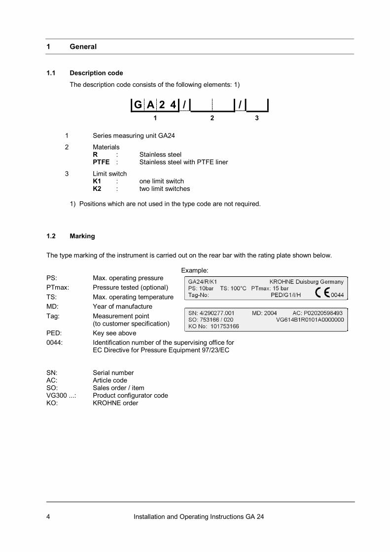
The description code consists of the following elements: 1)
G A 2 4 / /1 2 3
1 Series measuring unit GA24
2 Materials R : Stainless steel PTFE : Stainless steel with PTFE liner
3 Limit switch K1 : one limit switch K2 : two limit switches 1) Positions which are not used in the type code are not required. 1.2 Marking
The type marking of the instrument is carried out on the rear bar with the rating plate shown below. Example: PS: Max. operating pressure PTmax: Pressure tested (optional) TS: Max. operating temperature MD: Year of manufacture Tag: Measurement point (to customer specification) PED: Key see above 0044: Identification number of the supervising office for EC Directive for Pressure Equipment 97/23/EC SN: Serial number AC: Article code SO: Sales order / item VG300 ...: Product configurator code KO: KROHNE order
5 Installation and Operating Instructions GA 24
1.3 Key for Pressure Equipment Directive
PED / / /
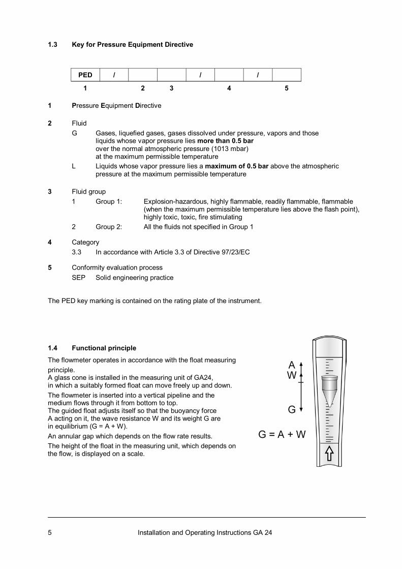
1 2 3 4 5 1 Pressure Equipment Directive 2 Fluid G Gases, liquefied gases, gases dissolved under pressure, vapors and those liquids whose vapor pressure lies more than 0.5 bar over the normal atmospheric pressure (1013 mbar) at the maximum permissible temperature L Liquids whose vapor pressure lies a maximum of 0.5 bar above the atmospheric pressure at the maximum permissible temperature 3 Fluid group
1 Group 1: Explosion-hazardous, highly flammable, readily flammable, flammable (when the maximum permissible temperature lies above the flash point), highly toxic, toxic, fire stimulating
2 Group 2: All the fluids not specified in Group 1 4 Category 3.3 In accordance with Article 3.3 of Directive 97/23/EC 5 Conformity evaluation process SEP Solid engineering practice The PED key marking is contained on the rating plate of the instrument. 1.4 Functional principle
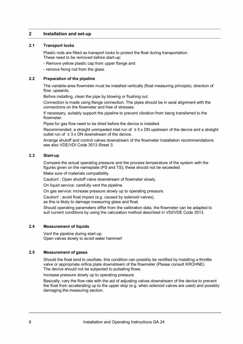
The flowmeter operates in accordance with the float measuring principle. A glass cone is installed in the measuring unit of GA24, in which a suitably formed float can move freely up and down. The flowmeter is inserted into a vertical pipeline and the medium flows through it from bottom to top. The guided float adjusts itself so that the buoyancy force A acting on it, the wave resistance W and its weight G are in equilibrium (G = A + W). An annular gap which depends on the flow rate results. The height of the float in the measuring unit, which depends on the flow, is displayed on a scale.
6 Installation and Operating Instructions GA 24
2 Installation and set-up 2.1 Transport locks
Plastic rods are fitted as transport locks to protect the float during transportation. These need to be removed before start-up: - Remove yellow plastic cap from upper flange and - remove fixing rod from the glass. 2.2 Preparation of the pipeline
The variable-area flowmeter must be installed vertically (float measuring principle), direction of flow: upwards. Before installing, clean the pipe by blowing or flushing out. Connection is made using flange connection. The pipes should be in axial alignment with the connections on the flowmeter and free of stresses. If necessary, suitably support the pipeline to prevent vibration from being transferred to the flowmeter. Pipes for gas flow need to be dried before the device is installed. Recommended: a straight unimpeded inlet run of ≥ 5 x DN upstream of the device and a straight outlet run of ≥ 3 x DN downstream of the device. Arrange shutoff and control valves downstream of the flowmeter Installation recommendations: see also VDE/VDI Code 3513 Sheet 3. 2.3 Start-up
Compare the actual operating pressure and the process temperature of the system with the figures given on the nameplate (PS and TS); these should not be exceeded. Make sure of materials compatibility. Caution! : Open shutoff valve downstream of flowmeter slowly. On liquid service: carefully vent the pipeline. On gas service: increase pressure slowly up to operating pressure. Caution! : avoid float impact (e.g. caused by solenoid valves), as this is likely to damage measuring glass and float. Should operating parameters differ from the calibration data, the flowmeter can be adapted to suit current conditions by using the calculation method described in VDI/VDE Code 3513. 2.4 Measurement of liquids
Vent the pipeline during start-up. Open valves slowly to avoid water hammer! 2.5 Measurement of gases
Should the float tend to oscillate, this condition can possibly be rectified by installing a throttle valve or appropriate orifice plate downstream of the flowmeter (Please consult KROHNE) The device should not be subjected to pulsating flows. Increase pressure slowly up to operating pressure. Basically, vary the flow rate with the aid of adjusting valves downstream of the device to prevent the float from accelerating up to the upper stop (e.g. when solenoid valves are used) and possibly damaging the measuring section.
7 Installation and Operating Instructions GA 24
2.6 Measured value
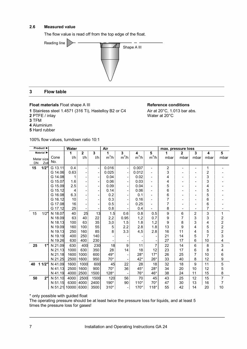
The flow value is read off from the top edge of the float. Reading line Shape A III
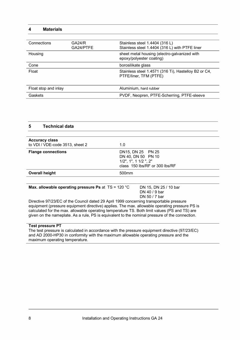
3 Flow table Float materials Float shape A III Reference conditions 1 Stainless steel 1.4571 (316 Ti), Hastelloy B2 or C4 Air at 20°C, 1.013 bar abs. 2 PTFE / inlay Water at 20°C 3 TFM 4 Aluminium 5 Hard rubber 100% flow values, turndown ratio 10:1
Product ► Water Air max. pressure loss 1 2 3 1 3 4 5 1 2 3 4 5 Material ►
Meter sizeDN Zoll
Cone No.
l/h l/h l/h m3/h m3/h m3/h m3/h mbar mbar mbar mbar mbar
15 1/2" G 13.11 0.4 - - 0.016 - 0.007 - 2 - - 1 - G 14.06 0.63 - - 0.025 - 0.012 - 3 - - 2 - G 14.08 1 - - 0.04 - 0.02 - 4 - - 3 - G 15.07 1.6 - - 0.06 - 0.03 - 4 - - 3 - G 15.09 2.5 - - 0.09 - 0.04 - 5 - - 4 - G 15.12 4 - - 0.14 - 0.06 - 6 - - 5 - G 16.08 6.3 - - 0.2 - 0.1 - 6 - - 5 - G 16.12 10 - - 0.3 - 0.16 - 7 - - 6 - G 17.08 16 - - 0.5 - 0.25 - 7 - - 6 - G 17.12 25 - - 0.8 - 0.4 - 8 - - 7 -
15 1/2" N 18.07 40 25 13 1.5 0.6 0.8 0.5 9 6 2 3 1 N 18.09 63 40 22 2,2 0.95 1,2 0.7 9 7 3 3 2 N 18.13 100 63 35 3,0 1.5 1.8 1,2 9 8 3 4 2 N 19.09 160 100 55 5 2.2 2.8 1.8 13 9 4 5 2 N 19.13 250 160 85 8 3.3 4,5 2.8 16 11 4 5 2 N 19.19 400 250 140 - - - - 21 14 5 7 3 N 19.26 630 400 230 - - - - 27 17 6 10 4
25 1" N 21.09 630 400 230 18 9 11 7 22 14 6 8 3 N 21.13 1000 630 350 28 14 18 12 23 17 6 8 4 N 21.18 1600 1000 600 49* - 28* 17* 26 25 7 10 6 N 21.25 2500 1600 950 70* - 42* 26* 33 40 8 12 9
40 1 1/2" N 41.09 1600 1000 600 45 22 28 18 32 18 9 11 5 N 41.13 2500 1600 900 70* 36 45* 28* 34 20 10 12 5 N 41.19 4000 2500 1500 128* - 76* 46* 38 24 11 15 8
50 2" N 51.10 4000 2500 1500 120 56 70 45 43 25 12 15 7 N 51.15 6300 4000 2400 190* 90 110* 70* 47 30 13 16 7 N 51.21 10000 6300 3500 310* - 170* 118* 55 42 14 20 10
* only possible with guided float The operating pressure should be at least twice the pressure loss for liquids, and at least 5 times the pressure loss for gases!
8 Installation and Operating Instructions GA 24
4 Materials Connections GA24/R GA24/PTFE
Stainless steel 1.4404 (316 L) Stainless steel 1.4404 (316 L) with PTFE liner
Housing sheet metal housing (electro-galvanized with epoxy/polyester coating)
Cone borosilikate glass Float Stainless steel 1.4571 (316 Ti), Hastelloy B2 or C4,
PTFE/liner, TFM (PTFE)
Float stop and inlay Aluminium, hard rubber
Gaskets PVDF, Neopren, PTFE-Scherring, PTFE-sleeve
5 Technical data
Accuracy class to VDI / VDE-code 3513, sheet 2
1.0
Flange connections
DN15, DN 25 PN 25 DN 40, DN 50 PN 10 1/2", 1", 1 1/2 ", 2" class 150 lbs/RF or 300 lbs/RF
Overall height 500mm
Max. allowable operating pressure Ps at TS = 120 °C
DN 15, DN 25 / 10 bar DN 40 / 9 bar DN 50 / 7 bar
Directive 97/23/EC of the Council dated 29 April 1999 concerning transportable pressure equipment (pressure equipment directive) applies. The max. allowable operating pressure PS is calculated for the max. allowable operating temperature TS. Both limit values (PS and TS) are given on the nameplate. As a rule, PS is equivalent to the nominal pressure of the connection. Test pressure PT The test pressure is calculated in accordance with the pressure equipment directive (97/23/EC) and AD 2000-HP30 in conformity with the maximum allowable operating pressure and the maximum operating temperature.
9 Installation and Operating Instructions GA 24
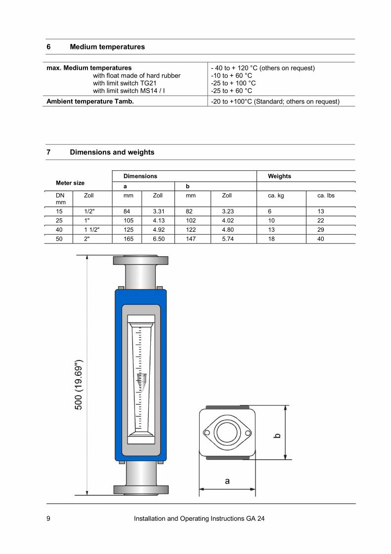
6 Medium temperatures max. Medium temperatures with float made of hard rubber with limit switch TG21 with limit switch MS14 / I
- 40 to + 120 °C (others on request) -10 to + 60 °C -25 to + 100 °C -25 to + 60 °C
Ambient temperature Tamb. -20 to +100°C (Standard; others on request)
7 Dimensions and weights
Dimensions Weights Meter size a b DN mm
Zoll mm Zoll mm Zoll ca. kg ca. lbs
15 1/2" 84 3.31 82 3.23 6 13 25 1" 105 4.13 102 4.02 10 22 40 1 1/2" 125 4.92 122 4.80 13 29 50 2" 165 6.50 147 5.74 18 40
10 Installation and Operating Instructions GA 24
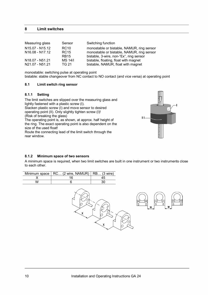
8 Limit switches Measuring glass Sensor Switching function N15.07 - N15.12 RC10 monostable or bistable, NAMUR, ring sensor N16.08 - N17.12 RC15 monostable or bistable, NAMUR, ring sensor RB15 bistable, 3-wire, non-“Ex“, ring sensor N18.07 - N51.21 MS 14/I bistable, floating, float with magnet N21.07 - N51.21 TG 21 bistable, NAMUR, float with magnet monostable: switching pulse at operating point bistable: stable changeover from NC contact to NO contact (and vice versa) at operating point 8.1 Limit switch ring sensor
8.1.1 Setting The limit switches are slipped over the measuring glass and lightly fastened with a plastic screw (I). Slacken plastic screw (I) and move sensor to desired operating point (II). Only slightly tighten screw (I)! (Risk of breaking the glass) The operating point is, as shown, at approx. half height of the ring. The exact operating point is also dependent on the size of the used float! Route the connecting lead of the limit switch through the rear window. 8.1.2 Minimum space of two sensors A minimum space is required, when two limit switches are built in one instrument or two instruments close to each other. Minimum space RC… (2 wire, NAMUR) RB… (3 wire)
X 16 45 W 6 30
11 Installation and Operating Instructions GA 24
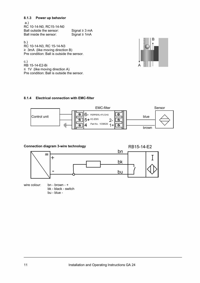
8.1.3 Power up behavior a.) RC 10-14-N0, RC15-14-N0 Ball outside the sensor: Signal ≥ 3 mA Ball inside the sensor: Signal ≥ 1mA b.) RC 10-14-N3, RC 15-14-N3 ≥ 3mA (like moving direction B) Pre condition: Ball is outside the sensor. c.) RB 15-14-E2-Bi ≤ 1V (like moving direction A) Pre condition: Ball is outside the sensor. 8.1.4 Electrical connection with EMC-filter EMC-filter Sensor Control unit blue
brown Connection diagram 3-wire technology wire colour: bn - brown - + bk - black - switch bu - blue -
12 Installation and Operating Instructions GA 24
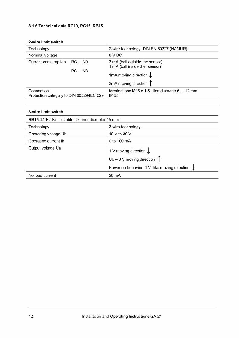
8.1.6 Technical data RC10, RC15, RB15 2-wire limit switch Technology 2-wire technology, DIN EN 50227 (NAMUR) Nominal voltage 8 V DC Current consumption RC ... N0 RC ... N3
3 mA (ball outside the sensor) 1 mA (ball inside the sensor)
1mA moving direction ↓
3mA moving direction ↑
Connection Protection category to DIN 60529/IEC 529
terminal box M16 x 1,5: line diameter 6 ... 12 mm IP 55
3-wire limit switch
RB15-14-E2-Bi - bistable, Ø inner diameter 15 mm
Technology 3-wire technology
Operating voltage Ub 10 V to 30 V
Operating current Ib 0 to 100 mA
Output voltage Ua
1 V moving direction ↓
Ub – 3 V moving direction ↑ Power up behavior 1 V like moving direction ↓
No load current 20 mA
13 Installation and Operating Instructions GA 24
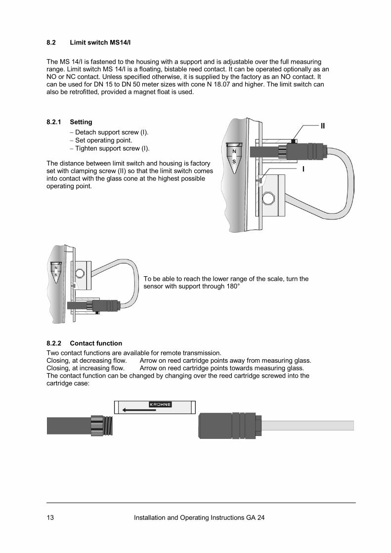
8.2 Limit switch MS14/I
The MS 14/I is fastened to the housing with a support and is adjustable over the full measuring range. Limit switch MS 14/I is a floating, bistable reed contact. It can be operated optionally as an NO or NC contact. Unless specified otherwise, it is supplied by the factory as an NO contact. It can be used for DN 15 to DN 50 meter sizes with cone N 18.07 and higher. The limit switch can also be retrofitted, provided a magnet float is used. 8.2.1 Setting − Detach support screw (I). − Set operating point. − Tighten support screw (I). The distance between limit switch and housing is factory set with clamping screw (II) so that the limit switch comes into contact with the glass cone at the highest possible operating point. To be able to reach the lower range of the scale, turn the sensor with support through 180°
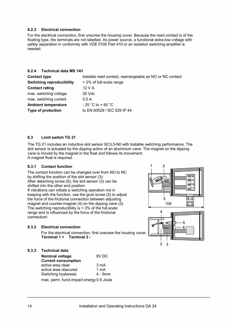
8.2.2 Contact function Two contact functions are available for remote transmission. Closing, at decreasing flow. Arrow on reed cartridge points away from measuring glass. Closing, at increasing flow. Arrow on reed cartridge points towards measuring glass. The contact function can be changed by changing over the reed cartridge screwed into the cartridge case:
14 Installation and Operating Instructions GA 24
8.2.3 Electrical connection For the electrical connection, first unscrew the housing cover. Because the reed contact is of the floating type, the terminals are not labelled. As power source, a functional extra-low voltage with safety separation in conformity with VDE 0100 Part 410 or an isolation switching amplifier is needed. 8.2.4 Technical data MS 14/I Contact type bistable reed contact, rearrangeable as NO or NC contact Switching reproducibility < 2% of full-scale range Contact rating 12 V A max. switching voltage 30 Vdc max. switching current 0.5 A Ambient temperature - 25 °C to + 60 °C Type of protection to EN 60529 / IEC 529 IP 44
8.3 Limit switch TG 21
The TG 21 includes an inductive slot sensor SC3,5-N0 with bistable switching performance. The slot sensor is actuated by the dipping action of an aluminium vane. The magnet on the dipping vane is moved by the magnet in the float and follows its movement. A magnet float is required. 8.3.1 Contact function The contact function can be changed over from NO to NC by shifting the position of the slot sensor (3): After detaching screw (6), the slot sensor (3) can be shifted into the other end position. If vibrations can initiate a switching operation not in keeping with the function, use the grub screw (5) to adjust the force of the frictional connection between adjusting magnet and counter-magnet (4) on the dipping vane (2). 104 The switching reproducibility is < 3% of the full-scale range and is influenced by the force of the frictional connection! 8.3.2 Electrical connection For the electrical connection, first unscrew the housing cover. Terminal 1 + Terminal 2 - 8.3.3 Technical data Nominal voltage 8V DC Current consumption active area clear 3 mA active area obscured 1 mA Switching hysteresis 4 - 5mm max. perm. funct.impact energy 0,5 Joule
15 Installation and Operating Instructions GA 24
9 Maintenance Within the scope of routine maintenance of the system and pipelines, the flowmeter should also be inspected for signs of soiling, corrosive attack and mechanical wear or damage to the measuring glass. We advise that inspections be carried out at least once a year. Note Pressurized pipes to be depressurized before removing the device. Devices used for measurement of aggressive media: take appropriate safety precautions regarding residual liquid in the measuring section. Always use new gaskets when reinstalling the flowmeter in the pipeline. Cleaning of surfaces (e.g. viewing window): avoid electrostatic charges!
If you need to return a device for testing or repair to KROHNE Your instrument has been manufactured carefully and tested several times. If installed and operated in accordance with these instructions your instrument will rarely present any problems. Should you nevertheless need to return an instrument for checking or repair, please pay strict attention to the following points: Due to statutory regulations concerning protection of the environment and safeguarding the health and safety of our personnel, KROHNE may only handle, test and repair returned instruments that have been in contact with liquids if it is possible to do so without risk to personnel and environment. This means that KROHNE can only service your device if it is accompanied by a certificate in line with the following model confirming that the device is safe to handle.
If the instrument has been operated with toxic, caustic, flammable or water-endangering liquids, you are kindly requested: ● To check and ensure, if necessary by rinsing or neutralizing, that all the cavities in the instrument are free from such dangerous substances. (Directions on how you can find out whether the primary head has to be opened and flushed out and neutralized are obtainable from KROHNE on request.) ● To enclose a certificate with the device confirming that the device is safe to handle and stating the liquid used. KROHNE regret that we cannot service your device unless it is accompanied by such a certificate and thank you for your understanding.
16 Installation and Operating Instructions GA 24
Form for returning the instrument Company: Address: Department: ................................................. Name: ..................................................................... Tel. No.: ....................................................... Fax. No.: ................................................................. The enclosed instrument Type: ...................................................................................................................................................... KROHNE Order No. or Series No.:.......................................................................................................... has been operated with the following process liquid: ............................................................................. Because this process liquid is water-endangering * / toxic * / caustic * / flammable * we have - Checked that all cavities in the instrument are free from such substances * - Flushed out and neutralized all cavities in the instrument * (* delete where not applicable) We confirm that there is no risk to man or environment through any residual liquid contained in the instrument. Date: ............................................................ Signature................................................................ Company stamp: